EP2088908B1 - Cloth rail - Google Patents
Cloth railDownload PDFInfo
- Publication number
- EP2088908B1 EP2088908B1EP07817951.2AEP07817951AEP2088908B1EP 2088908 B1EP2088908 B1EP 2088908B1EP 07817951 AEP07817951 AEP 07817951AEP 2088908 B1EP2088908 B1EP 2088908B1
- Authority
- EP
- European Patent Office
- Prior art keywords
- cloth
- wall
- rail
- magnets
- carrier part
- Prior art date
- Legal status (The legal status is an assumption and is not a legal conclusion. Google has not performed a legal analysis and makes no representation as to the accuracy of the status listed.)
- Not-in-force
Links
- 239000004744fabricSubstances0.000titleclaimsdescription59
- 229910001220stainless steelInorganic materials0.000claimsdescription2
- 239000010935stainless steelSubstances0.000claimsdescription2
- 239000000463materialSubstances0.000description7
- 238000004140cleaningMethods0.000description2
- BGPVFRJUHWVFKM-UHFFFAOYSA-NN1=C2C=CC=CC2=[N+]([O-])C1(CC1)CCC21N=C1C=CC=CC1=[N+]2[O-]Chemical compoundN1=C2C=CC=CC2=[N+]([O-])C1(CC1)CCC21N=C1C=CC=CC1=[N+]2[O-]BGPVFRJUHWVFKM-UHFFFAOYSA-N0.000description1
- 238000004026adhesive bondingMethods0.000description1
- 238000005034decorationMethods0.000description1
- 210000003298dental enamelAnatomy0.000description1
- 238000001035dryingMethods0.000description1
- 230000000694effectsEffects0.000description1
- 239000000696magnetic materialSubstances0.000description1
- 239000002184metalSubstances0.000description1
- 239000003973paintSubstances0.000description1
- 229920001296polysiloxanePolymers0.000description1
- 230000001681protective effectEffects0.000description1
- 238000004073vulcanizationMethods0.000description1
- 238000003466weldingMethods0.000description1
Images

Classifications
- A—HUMAN NECESSITIES
- A47—FURNITURE; DOMESTIC ARTICLES OR APPLIANCES; COFFEE MILLS; SPICE MILLS; SUCTION CLEANERS IN GENERAL
- A47K—SANITARY EQUIPMENT NOT OTHERWISE PROVIDED FOR; TOILET ACCESSORIES
- A47K10/00—Body-drying implements; Toilet paper; Holders therefor
- A47K10/04—Towel racks; Towel rails; Towel rods; Towel rolls, e.g. rotatable
- A47K10/08—Towel racks; Towel rails; Towel rods; Towel rolls, e.g. rotatable characterised by being mounted on wash-basins, baths, or the like
- A—HUMAN NECESSITIES
- A47—FURNITURE; DOMESTIC ARTICLES OR APPLIANCES; COFFEE MILLS; SPICE MILLS; SUCTION CLEANERS IN GENERAL
- A47K—SANITARY EQUIPMENT NOT OTHERWISE PROVIDED FOR; TOILET ACCESSORIES
- A47K10/00—Body-drying implements; Toilet paper; Holders therefor
- A47K10/04—Towel racks; Towel rails; Towel rods; Towel rolls, e.g. rotatable
- A47K10/10—Towel racks; Towel rails; Towel rods; Towel rolls, e.g. rotatable characterised by being mounted on cabinets, walls, doors, or the like
Definitions
- the present inventionrelates to cloth rails and in particular to cloth rails that can be attached to a wall without use of tools.
- an improved dishcloth railwould be advantageous, and in particular a more efficient and/or reliable dishcloth rail which can still be fastened without use of tools would be advantageous.
- a cloth railcomprising a carrier part adapted to carry a cloth and two pairs of magnets of which a first magnet is connected to the carrier part and a second magnet is separate and adapted to attract the first magnet according to claim 1.
- clothis meant any piece of cloth which it is desired to hang up e.g. for drying, for temporarily storing or for decoration.
- the cloth railmay also be used to carry more than one piece of clothes at a time.
- the second magnetis not directly connected to or abutting other parts of the cloth rail when in use, since the second magnet is placed on an opposite surface of a wall to which the cloth rail is attached.
- the second magnetmay typically abut the first magnet due to the magnetic attractive forces.
- wallis preferably meant a plate-like material having two substantially parallel opposite side surfaces. There must be access to both surfaces of the wall in order to be able to place the first magnet(s) on one surface and the second magnet(s) on the opposite surface.
- a wallmay e.g. be a kitchen sink or a cupboard door. It will also be possible to attach a cloth rail according to the present invention to another cloth, such as a tent wall.
- the cloth railcomprises the respective connecting parts forming each a connection between the first magnet(s) and the carrier part.
- Each connecting partmay comprise more than one piece so that the pieces together form the connection.
- the cloth railcomprises two connecting parts connected to opposite ends of the carrier part.
- the cloth railcomprises two pairs of magnets of which each first magnet is connected to the carrier part via a connecting part. In other embodiments not claimed the cloth rail comprises only one pair of magnets. It may also be possible to have three or more pairs of magnets.
- the magnetsmay have a cylindrical cross section, but any shape is possible within the scope of the invention.
- the cross section of the two magnets of a pair of magnetsmay be the same, or one may be larger than the other.
- the thicknessmay also be the same or different.
- the magnetsmay also be covered on one or more surfaces with e.g. paint, enamel or plastic for decorative or protective purposes.
- the carrier partmay be a rod. Alternatively it may be a chain, a flexible band, a plate or any other type of design that is appropriate for carrying a cloth.
- the connecting parts and carrier partmay be separable in such a way that the length of the cloth rail can be changed by changing the carrier part.
- An adjustable lengthmay also be obtained by use of a telescopic rod.
- the carrier part and the connecting part(s)are formed as one unit.
- the carrier partcan be made from any appropriate material including stainless steel and plastic.
- the choice of materialwill typically be a question of price, but it will also be related to other factors including aesthetic.
- a second aspect of the inventionrelates to a use of a cloth rail as described above for hanging up a cloth after having placed the first magnet(s) on one surface of a wall and, for each pair of magnets, placed the second magnet(s) on an opposite surface of the wall in such a way that the first and second magnets attract each other.
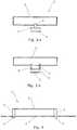
- FIG 1is a schematic top view of a cloth rail 1 attached to a wall 2 of a kitchen sink by use of two pairs of magnets 3,4.
- the sinkis illustrated as having a rectangular shape, but any shape that allows for attachment of the magnets is possible within the scope of the invention.
- Each pair of magnets 3,4comprises a first magnet 3 connected to the carrier part 5 of the cloth rail 1 and a second magnet 4 placed on an opposite side of the wall 2.
- the attractive forces of the magnetsmust be large enough to ensure that the cloth rail is securely fastened and still weak enough to allow for removal of the cloth rail.
- the strength of the magnetsmay therefore depend on the type of wall to which the cloth rail is to be attached.
- the carrier part 5 and the first magnets 3are interconnected by ring-shaped connecting parts 6, such as screw eyes.
- the same effectcan be obtained e.g. by hook-and-loop connections, but any type of connection providing a corresponding freedom of movement is possible within the scope of the invention.
- the two pairs of magnets 3,4are illustrated as attached to the same wall 2. It will however also be possible to attach the pair of magnets 3,4 to two different walls 2.
- FIG 2shows schematically an alternative embodiment wherein the connecting parts 6 are made from a bendable material, such as metal, silicone or plastic.
- the connecting partsare illustrated as being made from joints which are mutually moveable.
- each connecting part 6may also be made from one flexible piece of material having a smooth surface.
- the connecting parts 6may be connected with the carrier part 5 and the magnets 3,4 e.g. by gluing, welding, vulcanisation or screw connections.
- Figure 3shows schematically two embodiments not claimed having only one pair of magnets 3,4 which is preferably placed midway along the length of the carrier part 5.
- Two connecting parts 6, as shown in figure 3.bmay be used instead of one, as shown in figure 3.a , for stability, weight, or aesthetic reasons.
- Figure 4shows schematically not claimed where the carrier part 5 is attached directly to the first magnets 3, i.e. without the need for connecting parts 6.
- the first magnets 3must have a size which ensures that a cloth (not shown) can easily be placed between the carrier part 5 and the wall 2 to which the cloth rail 1 is attached.
- the carrier part 5is made from a magnetic material, it can be attached to the first magnets 3 by magnetic forces only. The correct positioning may furthermore be ensured by having grooves (not shown) in the magnets 3 with a shape corresponding to the cross section of the carrier part 5.
- the carrier part 5can easily be removed from the cloth rail 1 whereby the surface of a wall, such as a kitchen sink, to which the cloth rail 1 is attached can be cleaned without removal of the magnets.
- a wallsuch as a kitchen sink
- a cloth rail 1 according to the inventionmay be one assembled unit, except for the second magnets 4.
- the carrier part 5 and the connecting parts 6may be one unit adapted to be fastened to the first magnets 3.
- the carrier part 5is exchangeable, e.g. if another length is desired, or if it is broken or miscoloured. This may be possible by use of hook-and-loop connections or any other easily separable connections which will be well-known to a person skilled in the art.
- the cloth carrier 1can be attached to the wall 2 by holding the first magnets 3 close to one surface of the wall 2 and placing the second magnets 4 on the opposite surface of the wall 2. If the wall 2 is made from a material attracted by magnets, the first magnets 3 with the carrier part 5 may be attached to the wall 2 even without the second magnets 4, not falling under the scope of the claims, which are thereafter attached to the opposite surface of the wall 2 to ensure that the cloth carrier 1 stays in place also when a cloth is hung thereon.
Landscapes
- Health & Medical Sciences (AREA)
- Public Health (AREA)
- Supports Or Holders For Household Use (AREA)
Description
- The present invention relates to cloth rails and in particular to cloth rails that can be attached to a wall without use of tools.
- It is well-known that in many kitchens the dishcloth is often laid on the table or hung over the tap after use. This may be unhygienic, and many people find it unpleasant. A possible solution to these problems is to use a separate dish cloth holder that can be placed next to the sink. An alternative solution is known from
US5,217,123 which discloses a rail for hanging a dishcloth on the inside surface of a kitchen sink. The rail is attached by use of two suction cups which can be attached to any smooth surface without the need to damage, such as drill holes in, the sink and without use of tools. A similar rail is known fromUS 2006/0026748 , which rail is more flexible with respect to length and angular attachment. However, it may be difficult or impossible to attach suction cups to an uneven or dirty surface, especially if the suction cups are worn. Furthermore, even after attachment of the suction cups, they may get loose again after a while.US 2,977,082 discloses a cloth rail according the preamble ofclaim 1. - Hence, an improved dishcloth rail would be advantageous, and in particular a more efficient and/or reliable dishcloth rail which can still be fastened without use of tools would be advantageous.
- It is an object of the present invention to provide a cloth rail which can be attached to a wall without use of tools. For some embodiments of the invention, it may be necessary to use tools to, temporarily or permanently, detach the cloth rail from the wall e.g. for cleaning.
- It is a further object of the present invention to provide a cloth rail which can be attached to a wall without any need to pierce the wall.
- It is a further object of the present invention to provide a cloth rail which can be attached to an uneven or dirty surface of a wall.
- It is a further object of the present invention to provide a cloth rail which can easily be temporarily removed e.g. for cleaning of the cloth rail and/or the wall to which it is attached.
- It is a further object of the present invention to provide an alternative to the prior art.
- Thus, the above described object and several other objects are intended to be obtained in a first aspect of the invention by providing a cloth rail comprising a carrier part adapted to carry a cloth and two pairs of magnets of which a first magnet is connected to the carrier part and a second magnet is separate and adapted to attract the first magnet according to
claim 1. - By "cloth" is meant any piece of cloth which it is desired to hang up e.g. for drying, for temporarily storing or for decoration. The cloth rail may also be used to carry more than one piece of clothes at a time.
- By "separate" is preferably meant that the second magnet is not directly connected to or abutting other parts of the cloth rail when in use, since the second magnet is placed on an opposite surface of a wall to which the cloth rail is attached. When the cloth rail is not attached to a wall, e.g. before being taken into use, the second magnet may typically abut the first magnet due to the magnetic attractive forces.
- By "wall" is preferably meant a plate-like material having two substantially parallel opposite side surfaces. There must be access to both surfaces of the wall in order to be able to place the first magnet(s) on one surface and the second magnet(s) on the opposite surface. Such a wall may e.g. be a kitchen sink or a cupboard door. It will also be possible to attach a cloth rail according to the present invention to another cloth, such as a tent wall.
- The cloth rail comprises the respective connecting parts forming each a connection between the first magnet(s) and the carrier part. Each connecting part may comprise more than one piece so that the pieces together form the connection.
- The cloth rail comprises two connecting parts connected to opposite ends of the carrier part.
- The cloth rail comprises two pairs of magnets of which each first magnet is connected to the carrier part via a connecting part. In other embodiments not claimed the cloth rail comprises only one pair of magnets. It may also be possible to have three or more pairs of magnets.
- The magnets may have a cylindrical cross section, but any shape is possible within the scope of the invention. The cross section of the two magnets of a pair of magnets may be the same, or one may be larger than the other. The thickness may also be the same or different. The magnets may also be covered on one or more surfaces with e.g. paint, enamel or plastic for decorative or protective purposes.
- The carrier part may be a rod. Alternatively it may be a chain, a flexible band, a plate or any other type of design that is appropriate for carrying a cloth.
- The connecting parts and carrier part may be separable in such a way that the length of the cloth rail can be changed by changing the carrier part. An adjustable length may also be obtained by use of a telescopic rod.
- In some embodiments of the invention, the carrier part and the connecting part(s) are formed as one unit.
- The carrier part can be made from any appropriate material including stainless steel and plastic. The choice of material will typically be a question of price, but it will also be related to other factors including aesthetic.
- A second aspect of the invention relates to a use of a cloth rail as described above for hanging up a cloth after having placed the first magnet(s) on one surface of a wall and, for each pair of magnets, placed the second magnet(s) on an opposite surface of the wall in such a way that the first and second magnets attract each other.
- These and other aspects of the invention will be apparent from and elucidated with reference to the embodiments described hereinafter. Although the invention is described with respect to a rail for hanging up a dishcloth, it may find use in a number of other applications where it is desired to hang up a cloth. This may be to hang up e.g. a towel or clothes on a cupboard door, a washcloth on a shower door or wall, or woven pictures for decorative purposes.
- The cloth rail according to the invention will now be described in more detail with regard to the accompanying figures. The figures show one way of implementing the present invention and are not to be construed as being limiting to other possible embodiments falling within the scope of the attached claim set.
Figure 1 is a schematic top view of a cloth rail attached to a sink by use of two pairs of magnets.Figure 2 shows schematically an alternative embodiment where the connecting parts are formed from a bendable material.Figures 3.a and 3.b show schematically two embodiments having only one pair of magnets not claimed.Figure 4 shows schematically an embodiment where the carrier part is attached directly to the first magnets, i.e. without the need for connecting parts not claimed.Figure 1 is a schematic top view of acloth rail 1 attached to awall 2 of a kitchen sink by use of two pairs ofmagnets magnets first magnet 3 connected to thecarrier part 5 of thecloth rail 1 and asecond magnet 4 placed on an opposite side of thewall 2. The attractive forces of the magnets must be large enough to ensure that the cloth rail is securely fastened and still weak enough to allow for removal of the cloth rail. The strength of the magnets may therefore depend on the type of wall to which the cloth rail is to be attached.- In the embodiment shown, the
carrier part 5 and thefirst magnets 3 are interconnected by ring-shaped connectingparts 6, such as screw eyes. The same effect can be obtained e.g. by hook-and-loop connections, but any type of connection providing a corresponding freedom of movement is possible within the scope of the invention. Infigure 1 the two pairs ofmagnets same wall 2. It will however also be possible to attach the pair ofmagnets different walls 2. Figure 2 shows schematically an alternative embodiment wherein the connectingparts 6 are made from a bendable material, such as metal, silicone or plastic. The connecting parts are illustrated as being made from joints which are mutually moveable. However, each connectingpart 6 may also be made from one flexible piece of material having a smooth surface. The connectingparts 6 may be connected with thecarrier part 5 and themagnets Figure 3 shows schematically two embodiments not claimed having only one pair ofmagnets carrier part 5. Two connectingparts 6, as shown infigure 3.b , may be used instead of one, as shown infigure 3.a , for stability, weight, or aesthetic reasons.Figure 4 shows schematically not claimed where thecarrier part 5 is attached directly to thefirst magnets 3, i.e. without the need for connectingparts 6. In this case thefirst magnets 3 must have a size which ensures that a cloth (not shown) can easily be placed between thecarrier part 5 and thewall 2 to which thecloth rail 1 is attached. If thecarrier part 5 is made from a magnetic material, it can be attached to thefirst magnets 3 by magnetic forces only. The correct positioning may furthermore be ensured by having grooves (not shown) in themagnets 3 with a shape corresponding to the cross section of thecarrier part 5.- In some embodiments of the invention, the
carrier part 5 can easily be removed from thecloth rail 1 whereby the surface of a wall, such as a kitchen sink, to which thecloth rail 1 is attached can be cleaned without removal of the magnets. This will e.g. be the case with the embodiment shown infigure 4 , but other designs which allow for such option will be obvious for a person skilled in the art. - A
cloth rail 1 according to the invention may be one assembled unit, except for thesecond magnets 4. Alternatively thecarrier part 5 and the connectingparts 6 may be one unit adapted to be fastened to thefirst magnets 3. It is also possible within the scope of the invention that thecarrier part 5 is exchangeable, e.g. if another length is desired, or if it is broken or miscoloured. This may be possible by use of hook-and-loop connections or any other easily separable connections which will be well-known to a person skilled in the art. - The
cloth carrier 1 can be attached to thewall 2 by holding thefirst magnets 3 close to one surface of thewall 2 and placing thesecond magnets 4 on the opposite surface of thewall 2. If thewall 2 is made from a material attracted by magnets, thefirst magnets 3 with thecarrier part 5 may be attached to thewall 2 even without thesecond magnets 4, not falling under the scope of the claims, which are thereafter attached to the opposite surface of thewall 2 to ensure that thecloth carrier 1 stays in place also when a cloth is hung thereon. - Although the present invention has been described in connection with the specified embodiments, it should not be construed as being in any way limited to the presented examples. The scope of the present invention is set out by the accompanying claim set. In the context of the claims, the terms "comprising" or "comprises" do not exclude other possible elements. Also, the mentioning of references such as "a" or "an" etc. should not be construed as excluding a plurality. The use of reference signs in the claims with respect to elements indicated in the figures shall also not be construed as limiting the scope of the invention. Furthermore, individual features mentioned in different claims, may possibly be advantageously combined, and the mentioning of these features in different claims does not exclude that a combination of features is not possible and advantageous, within the scope of the invention defined by the appended claims.
Claims (8)
- A cloth rail (1) that can be attached to two different walls without use of tools and can be attached to said walls without any need to pierce said walls, the cloth rail (1) comprising- a carrier part (5) adapted to carry a cloth and two bendable connecting parts (6) connected to opposite ends of the carrier part (5),- two pair of magnets (3,4) where each pair has a first magnet (3) placed on one surface of a wall of said walls and being connected to the carrier part (5) via the respective connecting part (6),the cloth rail beingcharacterised in that
a second magnet (4) which is not directly connected to or abutting other parts of the cloth rail when in use and being adapted to attract the first magnet (3) when placed on an opposite surface of the wall,
andin that the bendable connecting parts (6) provide a freedom of movement so that the cloth rail (1) can be attached to two different walls (2). - A cloth rail (1) according to claim 1, wherein the carrier part (5) is a rod.
- A cloth rail (1) according to claim 1 or 2, wherein the carrier part and the connecting parts are formed as one unit.
- A cloth rail (1) according to any of the preceding claims 1, 2, or 3, wherein at least the carrier part (5) is made from stainless steel.
- A cloth rail (1) according to any of claims 1-4, wherein at least the carrier part (5) is made from plastic.
- Use of a cloth rail (1) according to any of claims 1-5 for hanging up a cloth after having, for each pair of magnets (3,4), placed the first magnet (3) on one surface of a wall (2) and having placed the second magnet (4) on an opposite surface of the wall (2) in such a way that the first and second magnets (3,4) attract each other.
- Use according to claim 6, wherein the wall is a sink wall, preferably a kitchen sink wall.
- Use according to claims 6 or 7, wherein the cloth is a dish cloth.
Applications Claiming Priority (2)
| Application Number | Priority Date | Filing Date | Title |
|---|---|---|---|
| DKPA200601494 | 2006-11-15 | ||
| PCT/DK2007/050153WO2008058546A1 (en) | 2006-11-15 | 2007-10-24 | Cloth rail |
Publications (2)
| Publication Number | Publication Date |
|---|---|
| EP2088908A1 EP2088908A1 (en) | 2009-08-19 |
| EP2088908B1true EP2088908B1 (en) | 2016-07-20 |
Family
ID=38950814
Family Applications (1)
| Application Number | Title | Priority Date | Filing Date |
|---|---|---|---|
| EP07817951.2ANot-in-forceEP2088908B1 (en) | 2006-11-15 | 2007-10-24 | Cloth rail |
Country Status (5)
| Country | Link |
|---|---|
| US (1) | US20100072147A1 (en) |
| EP (1) | EP2088908B1 (en) |
| CN (1) | CN101605489A (en) |
| CA (1) | CA2705844A1 (en) |
| WO (1) | WO2008058546A1 (en) |
Families Citing this family (16)
| Publication number | Priority date | Publication date | Assignee | Title |
|---|---|---|---|---|
| DE102008049794A1 (en)* | 2008-09-30 | 2010-04-01 | Klein-Soetebier, Jens, Dr. | Device for attachment of shelves and containers for use in vanities and sinks and on work surfaces, is provided with container that is attached to magnetic material that contains magnet |
| US9115484B2 (en) | 2011-03-25 | 2015-08-25 | Elkay Manufacturing Company | Magnetic accessory attachment device for sink |
| US9339137B2 (en)* | 2013-12-19 | 2016-05-17 | Wade Nelson | Holding tool |
| CN103720307B (en)* | 2013-12-30 | 2016-08-17 | 浙江亚合大机电科技有限公司 | A kind of hanging support device |
| CA2882716A1 (en) | 2014-02-20 | 2015-08-20 | Elkay Manufacturing Company | Magnetic sink accessory system |
| CN105196451A (en)* | 2015-05-05 | 2015-12-30 | 苏州井上橡塑有限公司 | Electrolyzed suspension rod for special-shaped sealing rings |
| US9598812B1 (en)* | 2015-10-14 | 2017-03-21 | Nancy L. Beltran | Dishcloth drying apparatus and method |
| US20170273292A1 (en)* | 2016-03-22 | 2017-09-28 | Beto Engineering & Marketing Co., Ltd. | Fly catcher combination |
| CN106065989B (en)* | 2016-07-26 | 2018-10-19 | 贵州电网有限责任公司电力科学研究院 | Aluminum cylinder GIS device digital radial detects CR camera bags hanging method and its hanger |
| CN110847306B (en) | 2018-08-21 | 2022-09-27 | 科勒公司 | Front apron board water tank with interchangeable surface |
| US11324318B2 (en) | 2018-10-04 | 2022-05-10 | Kohler Co. | Apron front sink panel assembly |
| US11781302B2 (en) | 2020-01-24 | 2023-10-10 | Kohler Co. | Sink having removable apron and accessory systems |
| USD952808S1 (en) | 2020-01-24 | 2022-05-24 | Kohler Co. | Sink |
| US12123182B2 (en) | 2020-01-24 | 2024-10-22 | Kohler Co. | Method of manufacturing a sink system |
| US12066179B2 (en) | 2020-06-29 | 2024-08-20 | Kohler Co. | Sink lighting system |
| USD951674S1 (en)* | 2020-11-17 | 2022-05-17 | Lars Bang-Jensen | Holder for dish cloth |
Citations (1)
| Publication number | Priority date | Publication date | Assignee | Title |
|---|---|---|---|---|
| US2977082A (en)* | 1960-08-01 | 1961-03-28 | Arthur L Harris | Magnetic support |
Family Cites Families (32)
| Publication number | Priority date | Publication date | Assignee | Title |
|---|---|---|---|---|
| US502659A (en)* | 1893-08-01 | Curtain-rod and bracket | ||
| US584380A (en)* | 1897-06-15 | loveless | ||
| US502654A (en)* | 1893-08-01 | Manufacturing com | ||
| US428783A (en)* | 1890-05-27 | Henry kettbel and harry taylor | ||
| US924248A (en)* | 1907-08-15 | 1909-06-08 | Le Roy C Lazear | Curtain-rod. |
| US1229874A (en)* | 1916-03-30 | 1917-06-12 | James H Boye | Curtain-hanger. |
| US1403333A (en)* | 1920-06-01 | 1922-01-10 | Edward C Jinks | Curtain-rod bracket |
| US1453748A (en)* | 1920-11-19 | 1923-05-01 | Boye Needle Co | Curtain rod |
| US1391599A (en)* | 1921-03-10 | 1921-09-20 | Louis E Wood | Window-fixture |
| US1424337A (en)* | 1921-03-28 | 1922-08-01 | James H Boye | Curtain fixture |
| US1504825A (en)* | 1923-08-24 | 1924-08-12 | Irwin M Knopsnyder | Curtain bracket |
| US2639930A (en)* | 1949-12-22 | 1953-05-26 | Thornton Isaiah Vernon | Curtain rod and bracket therefor |
| US2637446A (en)* | 1950-02-28 | 1953-05-05 | B W Mfg Inc | Towel bar |
| US2617537A (en)* | 1950-03-24 | 1952-11-11 | Arthur E Henley | Combination hanger and rod |
| US4465198A (en)* | 1982-09-16 | 1984-08-14 | Jack Martin | Expandable towel rack |
| US5217123A (en)* | 1992-02-24 | 1993-06-08 | Riley Marion A | Rack for hanging a dishcloth on the inside wall of a kitchen sink |
| US5276596A (en)* | 1992-06-23 | 1994-01-04 | Krenzel Ronald L | Holder for a flashlight |
| US5746329A (en)* | 1995-08-28 | 1998-05-05 | Northrop Grumman Corporation | Hanger system |
| CA2289996C (en)* | 1999-11-12 | 2008-01-15 | Go Simon Sunatori | Magnetic wall decoration device |
| US20020088909A1 (en)* | 2001-01-10 | 2002-07-11 | Ted Chen | Hanger assembly |
| US6502794B1 (en)* | 2001-06-18 | 2003-01-07 | Tzu-Kuang Ting | Hanger device with suction cup |
| US6688479B2 (en)* | 2002-03-13 | 2004-02-10 | Shai-Wei Nei | U-shaped curtain rod with pivotable connecting arms |
| US6886958B1 (en)* | 2003-05-19 | 2005-05-03 | O'ryan Industries, Inc. | Optical coupler for use with light-transmissive above-counter sinks |
| DE202004006864U1 (en)* | 2004-04-29 | 2004-08-12 | Schultz, Andreas, Dipl.-Ing. (FH) | Universal magnet holding rail is for fixture to wall or ceiling and can be used for kitchen knives or bath utensils |
| US7243806B2 (en)* | 2004-08-04 | 2007-07-17 | Golden Peak Plastic Works Limited | Bathroom rail |
| US7303299B2 (en)* | 2004-10-13 | 2007-12-04 | Theus Thomas S | Illuminated plumbing fixtures |
| DE202004016497U1 (en)* | 2004-10-26 | 2004-12-30 | Ackermann, Angela, Dipl.-Ing. (FH) | Mounting for bathroom accessories, e.g. shelves, comprises plate with metal casing which is screwed to wall, accessory having magnets fitted on its rear edge which attach it to plate |
| US7226026B2 (en)* | 2005-06-22 | 2007-06-05 | Christina Lin | Suction device |
| US20070040081A1 (en)* | 2005-08-22 | 2007-02-22 | Dietz Dan L | Impact guard system for devices |
| JP2007068828A (en)* | 2005-09-08 | 2007-03-22 | Motoyuki Fujiwara | Article supporting appliance |
| FI119753B (en)* | 2006-06-12 | 2009-03-13 | Magisso Oy | Suspendable hanging and storage tools in the sink |
| US7874025B2 (en)* | 2008-02-26 | 2011-01-25 | Liberty Hardware Mfg. Corp. | Grab bar assembly for shower and the like |
- 2007
- 2007-10-24EPEP07817951.2Apatent/EP2088908B1/ennot_activeNot-in-force
- 2007-10-24USUS12/514,995patent/US20100072147A1/ennot_activeAbandoned
- 2007-10-24CNCNA200780042451XApatent/CN101605489A/enactivePending
- 2007-10-24WOPCT/DK2007/050153patent/WO2008058546A1/enactiveApplication Filing
- 2007-10-24CACA2705844Apatent/CA2705844A1/ennot_activeAbandoned
Patent Citations (1)
| Publication number | Priority date | Publication date | Assignee | Title |
|---|---|---|---|---|
| US2977082A (en)* | 1960-08-01 | 1961-03-28 | Arthur L Harris | Magnetic support |
Also Published As
| Publication number | Publication date |
|---|---|
| EP2088908A1 (en) | 2009-08-19 |
| CA2705844A1 (en) | 2008-05-22 |
| CN101605489A (en) | 2009-12-16 |
| WO2008058546A1 (en) | 2008-05-22 |
| US20100072147A1 (en) | 2010-03-25 |
Similar Documents
| Publication | Publication Date | Title |
|---|---|---|
| EP2088908B1 (en) | Cloth rail | |
| US10455988B2 (en) | Magnetized accessory system for bath or shower walls | |
| JP5155319B2 (en) | Wall-mounted wire grid organizer system with removable accessories | |
| FI119753B (en) | Suspendable hanging and storage tools in the sink | |
| USD513142S1 (en) | Corner bath caddy | |
| USD624992S1 (en) | Plumbing fixture | |
| USD585119S1 (en) | Plumbing fixture | |
| US10722061B2 (en) | Personal use accessory | |
| US20200214483A1 (en) | Eating utensil support assembly | |
| US20200288896A1 (en) | Shower curtain valance interchange | |
| USD540086S1 (en) | Support bar | |
| US20230313511A1 (en) | Shower Head Hanger | |
| USD620344S1 (en) | Shower curtain hook | |
| EP1681005A1 (en) | Cleaning device and method | |
| USD565411S1 (en) | Hang tag | |
| USD528336S1 (en) | Support accessory | |
| EP3366177B1 (en) | Device for supporting kitchen objects | |
| HK1135297A (en) | Cloth rail | |
| USD564643S1 (en) | Plumbing fitting | |
| US20160195217A1 (en) | Method and apparatus for releasably attaching towels window coverings window treatments clothing rugs bathroom fixtures and accessories kitchen fixtures and accessories closet fixtures and accessories paper towels toilet tissue fabrics and the like to a surface | |
| KR102644789B1 (en) | A Magnet Securing Type of a Hanger for a Spoon Set | |
| USD568973S1 (en) | Plumbing fitting | |
| KR200201055Y1 (en) | A cooking utensils hanger | |
| KR200464816Y1 (en) | The shelf deferment unit where the establishment is possible in the form which is various | |
| KR200232267Y1 (en) | Lathe of detachable type |
Legal Events
| Date | Code | Title | Description |
|---|---|---|---|
| PUAI | Public reference made under article 153(3) epc to a published international application that has entered the european phase | Free format text:ORIGINAL CODE: 0009012 | |
| 17P | Request for examination filed | Effective date:20090612 | |
| AK | Designated contracting states | Kind code of ref document:A1 Designated state(s):AT BE BG CH CY CZ DE DK EE ES FI FR GB GR HU IE IS IT LI LT LU LV MC MT NL PL PT RO SE SI SK TR | |
| DAX | Request for extension of the european patent (deleted) | ||
| RAP1 | Party data changed (applicant data changed or rights of an application transferred) | Owner name:VILSTRUP, LINE REENBERG Owner name:REENBERG, GRETHE | |
| RIN1 | Information on inventor provided before grant (corrected) | Inventor name:VILSTRUP, LINE REENBERG Inventor name:REENBERG, GRETHE | |
| 17Q | First examination report despatched | Effective date:20150511 | |
| GRAP | Despatch of communication of intention to grant a patent | Free format text:ORIGINAL CODE: EPIDOSNIGR1 | |
| INTG | Intention to grant announced | Effective date:20160209 | |
| GRAS | Grant fee paid | Free format text:ORIGINAL CODE: EPIDOSNIGR3 | |
| GRAA | (expected) grant | Free format text:ORIGINAL CODE: 0009210 | |
| AK | Designated contracting states | Kind code of ref document:B1 Designated state(s):AT BE BG CH CY CZ DE DK EE ES FI FR GB GR HU IE IS IT LI LT LU LV MC MT NL PL PT RO SE SI SK TR | |
| REG | Reference to a national code | Ref country code:GB Ref legal event code:FG4D | |
| REG | Reference to a national code | Ref country code:CH Ref legal event code:EP | |
| REG | Reference to a national code | Ref country code:IE Ref legal event code:FG4D | |
| REG | Reference to a national code | Ref country code:AT Ref legal event code:REF Ref document number:813296 Country of ref document:AT Kind code of ref document:T Effective date:20160815 | |
| REG | Reference to a national code | Ref country code:DE Ref legal event code:R096 Ref document number:602007047106 Country of ref document:DE | |
| REG | Reference to a national code | Ref country code:SE Ref legal event code:TRGR | |
| REG | Reference to a national code | Ref country code:LT Ref legal event code:MG4D | |
| REG | Reference to a national code | Ref country code:NL Ref legal event code:MP Effective date:20160720 | |
| REG | Reference to a national code | Ref country code:AT Ref legal event code:MK05 Ref document number:813296 Country of ref document:AT Kind code of ref document:T Effective date:20160720 | |
| PG25 | Lapsed in a contracting state [announced via postgrant information from national office to epo] | Ref country code:IS Free format text:LAPSE BECAUSE OF FAILURE TO SUBMIT A TRANSLATION OF THE DESCRIPTION OR TO PAY THE FEE WITHIN THE PRESCRIBED TIME-LIMIT Effective date:20161120 Ref country code:LT Free format text:LAPSE BECAUSE OF FAILURE TO SUBMIT A TRANSLATION OF THE DESCRIPTION OR TO PAY THE FEE WITHIN THE PRESCRIBED TIME-LIMIT Effective date:20160720 Ref country code:NL Free format text:LAPSE BECAUSE OF FAILURE TO SUBMIT A TRANSLATION OF THE DESCRIPTION OR TO PAY THE FEE WITHIN THE PRESCRIBED TIME-LIMIT Effective date:20160720 Ref country code:IT Free format text:LAPSE BECAUSE OF FAILURE TO SUBMIT A TRANSLATION OF THE DESCRIPTION OR TO PAY THE FEE WITHIN THE PRESCRIBED TIME-LIMIT Effective date:20160720 Ref country code:FI Free format text:LAPSE BECAUSE OF FAILURE TO SUBMIT A TRANSLATION OF THE DESCRIPTION OR TO PAY THE FEE WITHIN THE PRESCRIBED TIME-LIMIT Effective date:20160720 | |
| PG25 | Lapsed in a contracting state [announced via postgrant information from national office to epo] | Ref country code:ES Free format text:LAPSE BECAUSE OF FAILURE TO SUBMIT A TRANSLATION OF THE DESCRIPTION OR TO PAY THE FEE WITHIN THE PRESCRIBED TIME-LIMIT Effective date:20160720 Ref country code:PT Free format text:LAPSE BECAUSE OF FAILURE TO SUBMIT A TRANSLATION OF THE DESCRIPTION OR TO PAY THE FEE WITHIN THE PRESCRIBED TIME-LIMIT Effective date:20161121 Ref country code:LV Free format text:LAPSE BECAUSE OF FAILURE TO SUBMIT A TRANSLATION OF THE DESCRIPTION OR TO PAY THE FEE WITHIN THE PRESCRIBED TIME-LIMIT Effective date:20160720 Ref country code:BE Free format text:LAPSE BECAUSE OF NON-PAYMENT OF DUE FEES Effective date:20160720 Ref country code:GR Free format text:LAPSE BECAUSE OF FAILURE TO SUBMIT A TRANSLATION OF THE DESCRIPTION OR TO PAY THE FEE WITHIN THE PRESCRIBED TIME-LIMIT Effective date:20161021 Ref country code:PL Free format text:LAPSE BECAUSE OF FAILURE TO SUBMIT A TRANSLATION OF THE DESCRIPTION OR TO PAY THE FEE WITHIN THE PRESCRIBED TIME-LIMIT Effective date:20160720 Ref country code:AT Free format text:LAPSE BECAUSE OF FAILURE TO SUBMIT A TRANSLATION OF THE DESCRIPTION OR TO PAY THE FEE WITHIN THE PRESCRIBED TIME-LIMIT Effective date:20160720 | |
| REG | Reference to a national code | Ref country code:DE Ref legal event code:R097 Ref document number:602007047106 Country of ref document:DE | |
| PG25 | Lapsed in a contracting state [announced via postgrant information from national office to epo] | Ref country code:EE Free format text:LAPSE BECAUSE OF FAILURE TO SUBMIT A TRANSLATION OF THE DESCRIPTION OR TO PAY THE FEE WITHIN THE PRESCRIBED TIME-LIMIT Effective date:20160720 Ref country code:RO Free format text:LAPSE BECAUSE OF FAILURE TO SUBMIT A TRANSLATION OF THE DESCRIPTION OR TO PAY THE FEE WITHIN THE PRESCRIBED TIME-LIMIT Effective date:20160720 | |
| PLBE | No opposition filed within time limit | Free format text:ORIGINAL CODE: 0009261 | |
| STAA | Information on the status of an ep patent application or granted ep patent | Free format text:STATUS: NO OPPOSITION FILED WITHIN TIME LIMIT | |
| PG25 | Lapsed in a contracting state [announced via postgrant information from national office to epo] | Ref country code:BG Free format text:LAPSE BECAUSE OF FAILURE TO SUBMIT A TRANSLATION OF THE DESCRIPTION OR TO PAY THE FEE WITHIN THE PRESCRIBED TIME-LIMIT Effective date:20161020 Ref country code:CZ Free format text:LAPSE BECAUSE OF FAILURE TO SUBMIT A TRANSLATION OF THE DESCRIPTION OR TO PAY THE FEE WITHIN THE PRESCRIBED TIME-LIMIT Effective date:20160720 Ref country code:DK Free format text:LAPSE BECAUSE OF FAILURE TO SUBMIT A TRANSLATION OF THE DESCRIPTION OR TO PAY THE FEE WITHIN THE PRESCRIBED TIME-LIMIT Effective date:20160720 Ref country code:SK Free format text:LAPSE BECAUSE OF FAILURE TO SUBMIT A TRANSLATION OF THE DESCRIPTION OR TO PAY THE FEE WITHIN THE PRESCRIBED TIME-LIMIT Effective date:20160720 | |
| REG | Reference to a national code | Ref country code:CH Ref legal event code:PL | |
| 26N | No opposition filed | Effective date:20170421 | |
| REG | Reference to a national code | Ref country code:IE Ref legal event code:MM4A | |
| REG | Reference to a national code | Ref country code:FR Ref legal event code:ST Effective date:20170630 | |
| PG25 | Lapsed in a contracting state [announced via postgrant information from national office to epo] | Ref country code:LI Free format text:LAPSE BECAUSE OF NON-PAYMENT OF DUE FEES Effective date:20161031 Ref country code:FR Free format text:LAPSE BECAUSE OF NON-PAYMENT OF DUE FEES Effective date:20161102 Ref country code:CH Free format text:LAPSE BECAUSE OF NON-PAYMENT OF DUE FEES Effective date:20161031 | |
| PG25 | Lapsed in a contracting state [announced via postgrant information from national office to epo] | Ref country code:LU Free format text:LAPSE BECAUSE OF NON-PAYMENT OF DUE FEES Effective date:20161024 Ref country code:SI Free format text:LAPSE BECAUSE OF FAILURE TO SUBMIT A TRANSLATION OF THE DESCRIPTION OR TO PAY THE FEE WITHIN THE PRESCRIBED TIME-LIMIT Effective date:20160720 | |
| PG25 | Lapsed in a contracting state [announced via postgrant information from national office to epo] | Ref country code:IE Free format text:LAPSE BECAUSE OF NON-PAYMENT OF DUE FEES Effective date:20161024 | |
| PG25 | Lapsed in a contracting state [announced via postgrant information from national office to epo] | Ref country code:CY Free format text:LAPSE BECAUSE OF FAILURE TO SUBMIT A TRANSLATION OF THE DESCRIPTION OR TO PAY THE FEE WITHIN THE PRESCRIBED TIME-LIMIT Effective date:20160720 Ref country code:HU Free format text:LAPSE BECAUSE OF FAILURE TO SUBMIT A TRANSLATION OF THE DESCRIPTION OR TO PAY THE FEE WITHIN THE PRESCRIBED TIME-LIMIT; INVALID AB INITIO Effective date:20071024 | |
| PG25 | Lapsed in a contracting state [announced via postgrant information from national office to epo] | Ref country code:MC Free format text:LAPSE BECAUSE OF FAILURE TO SUBMIT A TRANSLATION OF THE DESCRIPTION OR TO PAY THE FEE WITHIN THE PRESCRIBED TIME-LIMIT Effective date:20160720 Ref country code:MT Free format text:LAPSE BECAUSE OF NON-PAYMENT OF DUE FEES Effective date:20161031 Ref country code:TR Free format text:LAPSE BECAUSE OF FAILURE TO SUBMIT A TRANSLATION OF THE DESCRIPTION OR TO PAY THE FEE WITHIN THE PRESCRIBED TIME-LIMIT Effective date:20160720 | |
| PGFP | Annual fee paid to national office [announced via postgrant information from national office to epo] | Ref country code:DE Payment date:20211012 Year of fee payment:15 Ref country code:SE Payment date:20211012 Year of fee payment:15 Ref country code:GB Payment date:20211012 Year of fee payment:15 | |
| REG | Reference to a national code | Ref country code:DE Ref legal event code:R119 Ref document number:602007047106 Country of ref document:DE | |
| REG | Reference to a national code | Ref country code:SE Ref legal event code:EUG | |
| GBPC | Gb: european patent ceased through non-payment of renewal fee | Effective date:20221024 | |
| PG25 | Lapsed in a contracting state [announced via postgrant information from national office to epo] | Ref country code:DE Free format text:LAPSE BECAUSE OF NON-PAYMENT OF DUE FEES Effective date:20230503 | |
| PG25 | Lapsed in a contracting state [announced via postgrant information from national office to epo] | Ref country code:SE Free format text:LAPSE BECAUSE OF NON-PAYMENT OF DUE FEES Effective date:20221025 | |
| PG25 | Lapsed in a contracting state [announced via postgrant information from national office to epo] | Ref country code:GB Free format text:LAPSE BECAUSE OF NON-PAYMENT OF DUE FEES Effective date:20221024 |