EP2087849B1 - Hybrid contact quality monitoring return electrode - Google Patents
Hybrid contact quality monitoring return electrodeDownload PDFInfo
- Publication number
- EP2087849B1 EP2087849B1EP09152130.2AEP09152130AEP2087849B1EP 2087849 B1EP2087849 B1EP 2087849B1EP 09152130 AEP09152130 AEP 09152130AEP 2087849 B1EP2087849 B1EP 2087849B1
- Authority
- EP
- European Patent Office
- Prior art keywords
- electrode
- return electrode
- intermediary layer
- patient
- electrosurgical
- Prior art date
- Legal status (The legal status is an assumption and is not a legal conclusion. Google has not performed a legal analysis and makes no representation as to the accuracy of the status listed.)
- Not-in-force
Links
- 238000012544monitoring processMethods0.000titleclaimsdescription35
- 239000004020conductorSubstances0.000claimsdescription40
- 238000000034methodMethods0.000claimsdescription18
- 229910052751metalInorganic materials0.000claimsdescription13
- 239000002184metalSubstances0.000claimsdescription13
- 238000000151depositionMethods0.000claimsdescription9
- 239000003989dielectric materialSubstances0.000claimsdescription8
- BQCADISMDOOEFD-UHFFFAOYSA-NSilverChemical compound[Ag]BQCADISMDOOEFD-UHFFFAOYSA-N0.000claimsdescription7
- 238000010438heat treatmentMethods0.000claimsdescription6
- 239000000463materialSubstances0.000claimsdescription6
- 229910052709silverInorganic materials0.000claimsdescription6
- 239000004332silverSubstances0.000claimsdescription6
- 229920006267polyester filmPolymers0.000claimsdescription5
- RYGMFSIKBFXOCR-UHFFFAOYSA-NCopperChemical compound[Cu]RYGMFSIKBFXOCR-UHFFFAOYSA-N0.000claimsdescription4
- 229910052802copperInorganic materials0.000claimsdescription4
- 239000010949copperSubstances0.000claimsdescription4
- PCHJSUWPFVWCPO-UHFFFAOYSA-NgoldChemical compound[Au]PCHJSUWPFVWCPO-UHFFFAOYSA-N0.000claimsdescription4
- 239000010931goldSubstances0.000claimsdescription4
- 229910052737goldInorganic materials0.000claimsdescription4
- 238000004519manufacturing processMethods0.000claimsdescription4
- 229920001721polyimidePolymers0.000claimsdescription4
- 238000007650screen-printingMethods0.000claimsdescription4
- 239000007787solidSubstances0.000claimsdescription4
- 239000010935stainless steelSubstances0.000claimsdescription4
- 229910001220stainless steelInorganic materials0.000claimsdescription4
- 101710187783Adherence factorProteins0.000claimsdescription3
- 239000000853adhesiveSubstances0.000description10
- 230000001070adhesive effectEffects0.000description10
- 238000010586diagramMethods0.000description4
- 238000013461designMethods0.000description3
- 230000000451tissue damageEffects0.000description3
- 231100000827tissue damageToxicity0.000description3
- 229920002799BoPETPolymers0.000description2
- 238000005516engineering processMethods0.000description2
- 230000006870functionEffects0.000description2
- 235000015110jelliesNutrition0.000description2
- 239000008274jellySubstances0.000description2
- 150000002739metalsChemical class0.000description2
- 238000012986modificationMethods0.000description2
- 230000004048modificationEffects0.000description2
- 238000001356surgical procedureMethods0.000description2
- 239000004820Pressure-sensitive adhesiveSubstances0.000description1
- 238000002679ablationMethods0.000description1
- 239000012190activatorSubstances0.000description1
- 229910045601alloyInorganic materials0.000description1
- 239000000956alloySubstances0.000description1
- 230000000740bleeding effectEffects0.000description1
- 239000008280bloodSubstances0.000description1
- 210000004369bloodAnatomy0.000description1
- 239000003990capacitorSubstances0.000description1
- 230000001112coagulating effectEffects0.000description1
- 230000015271coagulationEffects0.000description1
- 238000005345coagulationMethods0.000description1
- 238000010276constructionMethods0.000description1
- 230000007797corrosionEffects0.000description1
- 238000005260corrosionMethods0.000description1
- 238000005520cutting processMethods0.000description1
- 230000007423decreaseEffects0.000description1
- 230000003247decreasing effectEffects0.000description1
- 230000008021depositionEffects0.000description1
- 239000006185dispersionSubstances0.000description1
- 230000009977dual effectEffects0.000description1
- 229920005570flexible polymerPolymers0.000description1
- 239000011888foilSubstances0.000description1
- 238000002847impedance measurementMethods0.000description1
- 230000003993interactionEffects0.000description1
- 230000001788irregularEffects0.000description1
- 238000005259measurementMethods0.000description1
- 238000000465mouldingMethods0.000description1
- 238000010422paintingMethods0.000description1
- 229920006254polymer filmPolymers0.000description1
- 239000002861polymer materialSubstances0.000description1
- 239000000523sampleSubstances0.000description1
- 238000007789sealingMethods0.000description1
- 238000005507sprayingMethods0.000description1
Images


Classifications
- A—HUMAN NECESSITIES
- A61—MEDICAL OR VETERINARY SCIENCE; HYGIENE
- A61B—DIAGNOSIS; SURGERY; IDENTIFICATION
- A61B18/00—Surgical instruments, devices or methods for transferring non-mechanical forms of energy to or from the body
- A61B18/04—Surgical instruments, devices or methods for transferring non-mechanical forms of energy to or from the body by heating
- A61B18/12—Surgical instruments, devices or methods for transferring non-mechanical forms of energy to or from the body by heating by passing a current through the tissue to be heated, e.g. high-frequency current
- A61B18/14—Probes or electrodes therefor
- A61B18/16—Indifferent or passive electrodes for grounding
- A—HUMAN NECESSITIES
- A61—MEDICAL OR VETERINARY SCIENCE; HYGIENE
- A61B—DIAGNOSIS; SURGERY; IDENTIFICATION
- A61B18/00—Surgical instruments, devices or methods for transferring non-mechanical forms of energy to or from the body
- A61B2018/00636—Sensing and controlling the application of energy
- A61B2018/00696—Controlled or regulated parameters
- A61B2018/00702—Power or energy
- A—HUMAN NECESSITIES
- A61—MEDICAL OR VETERINARY SCIENCE; HYGIENE
- A61B—DIAGNOSIS; SURGERY; IDENTIFICATION
- A61B18/00—Surgical instruments, devices or methods for transferring non-mechanical forms of energy to or from the body
- A61B2018/00636—Sensing and controlling the application of energy
- A61B2018/00773—Sensed parameters
- A61B2018/00875—Resistance or impedance
- A—HUMAN NECESSITIES
- A61—MEDICAL OR VETERINARY SCIENCE; HYGIENE
- A61B—DIAGNOSIS; SURGERY; IDENTIFICATION
- A61B18/00—Surgical instruments, devices or methods for transferring non-mechanical forms of energy to or from the body
- A61B18/04—Surgical instruments, devices or methods for transferring non-mechanical forms of energy to or from the body by heating
- A61B18/12—Surgical instruments, devices or methods for transferring non-mechanical forms of energy to or from the body by heating by passing a current through the tissue to be heated, e.g. high-frequency current
- A61B18/14—Probes or electrodes therefor
- A61B18/16—Indifferent or passive electrodes for grounding
- A61B2018/167—Passive electrodes capacitively coupled to the skin
Definitions
- the present disclosurerelates to electrosurgical apparatuses, systems and methods. More particularly, the present disclosure is directed to electrosurgical systems utilizing one or more capacitive return electrodes configured to monitor contact quality thereof.
- Electrosurgeryinvolves application of high radio frequency electrical current to a surgical site to cut, ablate, coagulate or seal tissue.
- the active electrodeis typically part of the surgical instrument held by the surgeon and applied to the tissue to be treated.
- a patient return electrodeis placed remotely from the active electrode to carry the current back to the generator and safely disperse current applied by the active electrode.
- US 2005/0113817 A1discloses an electrosurgical return electrode for use in electrosurgery.
- an inductoris coupled in series with the return electrode, and the inductor counteracts at least a portion of the impedance of the return electrode and the patient to optimize the flow of the current when the amount of contact area between the patient and the return electrode is sufficient to perform electrosurgery.
- the return electrodesusually have a large patient contact surface area to minimize heating at that site. Heating is caused by high current densities which directly depend on the surface area. A larger surface contact area results in lower localized heat intensity. Return electrodes are typically sized based on assumptions of the maximum current utilized during a particular surgical procedure and the duty cycle (i.e., the percentage of time the generator is on).
- the first types of return electrodeswere in the form of large metal plates covered with conductive jelly. Later, adhesive electrodes were developed with a single metal foil covered with conductive jelly or conductive adhesive. However, one problem with these adhesive electrodes was that if a portion peeled from the patient, the contact area of the electrode with the patient decreased, thereby increasing the current density at the adhered portion and, in turn, increasing the heating at the tissue. This risked burning the patient in the area under the adhered portion of the return electrode if the tissue was heated beyond the point where circulation of blood could cool the skin.
- Return Electrode Contact Quality MonitorsCRCs
- Such systemsrelied on measuring impedance at the return electrode to calculate a variety of tissue and/or electrode properties. These systems were configured to measure changes in impedance of the return electrodes to detect peeling. Furthermore, the systems were designed to work with conventional resistive return electrodes.
- the present disclosurerelates to electrosurgical return electrodes. Disclosure provides for a hybrid return electrode having a capacitive return electrode and a resistive monitoring electrode which includes one or more pairs of split conductors. The dual nature of the hybrid return electrodes provides for increased heat dispersion as well as return electrode monitoring.
- an electrosurgical return electrodeincludes an intermediary layer formed from a dielectric material, the intermediary layer having a top surface and a patient-contacting surface.
- the return electrodealso includes a capacitive return electrode formed from a conductive material disposed on the top surface of the intermediary layer and a resistive monitoring electrode formed from a conductive material disposed on the patient-contact surface of the intermediary layer.
- an electrosurgical systemincludes one or more electrosurgical return electrodes, each of which includes an intermediary layer formed from a dielectric material, the intermediary layer having a top surface and a patient-contacting surface.
- the return electrodealso includes a capacitive return electrode formed from a conductive material disposed on the top surface of the intermediary layer and a resistive monitoring electrode formed from a conductive material disposed on the patient-contact surface of the intermediary layer.
- the resistive monitoring electrodeincludes one or more pairs of split electrode conductors.
- the systemalso includes a return electrode monitoring system coupled to one or more pairs of split electrode conductors and configured to measure impedance between the one or more pairs of split electrode conductors.
- a method for manufacturing an electrosurgical return electrodeincludes the steps of forming an intermediary layer from a dielectric material, the intermediary layer having a top surface and a patient-contacting surface, The method also includes the steps of depositing a first conductive material onto the top surface of the intermediary layer to form a capacitive return electrode and depositing a second conductive material onto the patient-contact surface of the intermediary layer to form a resistive monitoring electrode. The method further includes the step of heating the intermediary layer, capacitive return electrode and resistive monitoring electrode for a predetermined period of time at a temperature from about 70° C to about 120° C.
- a capacitive return electrodecan safely return more current than a return electrode incorporating a resistive design.
- conventional capacitive return electrodesare not configured to couple with a return electrode monitoring ("REM") system.
- the REM systemmonitors the adherence of the return electrode to the patient by measuring the impedance and/or current between one or more split conductors.
- Split conductor designsare incorporated into resistive return electrodes but previously are not included in capacitive return electrode designs due to the increased impedance of these return electrodes.
- the hybrid return electrodeincludes a dielectric layer and a solid metal layer (e.g., silver) deposited on a top (e.g., outside) surface providing for a capacitive configuration.
- the hybrid return electrodealso includes one or more pairs of split metallic conductors (e.g., silver foil) disposed on a bottom (e.g., patient contact) surface of the dielectric layer.
- the split metallic conductorsserve as a resistive monitoring electrode which is interrogated by the REM system to determine contact quality of the hybrid return electrode.
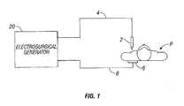
- Fig. 1is a schematic illustration of an electrosurgical system according to one embodiment of the present disclosure.
- the systemincludes an electrosurgical instrument 2 having one or more electrodes for treating tissue of a patient P.
- the instrument 2is a monopolar instrument including one or more active electrodes (e.g., electrosurgical cutting probe, ablation electrode(s), etc.).
- Electrosurgical RF energyis supplied to the instrument 2 by a generator 20 via an electrosurgical cable 4, which is connected to an active output terminal, allowing the instrument 2 to coagulate, ablate and/or otherwise treat tissue.
- the energyis returned to the generator 20 through a hybrid return electrode 6 via a return cable 8.
- the systemmay include a plurality of return electrodes 6 that are arranged to minimize the chances of tissue damage by maximizing the overall contact area with the patient P.
- the generator 20 and the return electrode 6may be configured for monitoring so-called "tissue-to-patient" contact to insure that sufficient contact exists therebetween to further minimize chances of tissue damage.
- the generator 20includes input controls (e.g., buttons, activators, switches, touch screen, etc.) for controlling the generator 20.
- the generator 20may include one or more display screens for providing the user with variety of output information (e.g., intensity settings, treatment complete indicators, etc.).
- the controlsallow the user to adjust power of the RF energy, waveform, and other parameters to achieve the desired waveform suitable for a particular task (e.g., coagulating, tissue sealing, intensity setting, etc.).
- the instrument 2may also include a plurality of input controls that may be redundant with certain input controls of the generator 20. Placing the input controls at the instrument 2 allows for easier and faster modification of RF energy parameters during the surgical procedure without requiring interaction with the generator 20.
- Fig. 2shows a schematic block diagram of the generator 20 having a controller 24, a high voltage DC power supply 27 ("HVPS”) and an RF output stage 28.
- the HVPS 27provides high voltage DC power to an RF output stage 28, which then converts high voltage DC power into RF energy and delivers the RF energy to the active electrode.
- the RF output stage 28generates sinusoidal waveforms of high RF energy.
- the RF output stage 28is configured to generate a plurality of waveforms having various duty cycles, peak voltages, crest factors, and other suitable parameters. Certain types of waveforms are suitable for specific electrosurgical modes.
- the RF output stage 28generates a 100% duty cycle sinusoidal waveform in cut mode, which is best suited for ablating, fusing and dissecting tissue, and a 1-25% duty cycle waveform in coagulation mode, which is best used for cauterizing tissue to stop bleeding.
- the controller 24includes a microprocessor 25 operably connected to a memory 26, which may be volatile type memory (e.g., RAM) and/or non-volatile type memory (e.g., flash media, disk media, etc.).
- the microprocessor 25includes an output port that is operably connected to the HVPS 27 and/or RF output stage 28 that allows the microprocessor 25 to control the output of the generator 20 according to either open and/or closed control loop schemes.
- the microprocessor 25may be substituted by any logic processor (e.g., control circuit) adapted to perform the calculations discussed herein.
- a closed loop control schemeis a feedback control loop wherein sensor circuit 22, which may include a plurality of sensors measuring a variety of tissue and energy properties (e.g., tissue impedance, tissue temperature, output current and/or voltage, etc.), provides feedback to the controller 24. Such sensors are within the purview of those skilled in the art.
- the controller 24then signals the HVPS 27 and/or RF output stage 28, which then adjust DC and/or RF power supply, respectively.
- the controller 24also receives input signals from the input controls of the generator 20 or the instrument 2.
- the controller 24utilizes the input signals to adjust power outputted by the generator 20 and/or performs other control functions thereon.
- the generator 20includes a return electrode monitoring system having an impedance monitor 30 which is coupled to a pair of split electrode conductors 31 and 32 disposed within the return electrode 6.
- the impedance sensor 30measures the impedance between the split electrode conductors 31 and 32 and transmits the measurements to the sensor circuit 22 which analyzes the impedance measurement to determine an adherence factor (e.g., the degree of adherence) of the return electrode 6 to the patient. If impedance between the split electrode conductors 31 and 32 decreases, the sensor circuit 22 recognizes that the return electrode 6 is peeling and notifies the user of the event via an alarm and/or terminates the supply of RF energy.
- an adherence factore.g., the degree of adherence
- Figs. 3-5illustrate the hybrid return electrode 6 having a top surface 34 and a patient-contacting surface 36. While the return electrode 6 is depicted as having a general rectangular shape, it is within the scope of the disclosure for the return electrode 6 to have any suitable regular or irregular shape.
- the return electrode 6may include an adhesive material layer on the patient-contacting surface 36.
- the adhesive materialcan be, but is not limited to, a polyhesive adhesive, a Z-axis adhesive, a water-insoluble, hydrophilic, pressure-sensitive adhesive, or any combinations thereof, such as POLYHESIVETM adhesive manufactured by Valleylab, a division of Covidien of Boulder, Colorado.
- the adhesivemay be conductive or dielectric.
- the adhesive material layerensures an optimal surface contact area between the electrosurgical return electrode 6 and the patient "P," which limits the possibility of a patient burn.
- the return electrode 6includes an intermediary dielectric layer 40 which can be formed from a variety of flexible polymer materials such as polyimide film sold under a trademark KAPTONTM and polyester film, such as biaxially-oriented polyethylene terephthalate (boPET) polyester film sold under trademarks MYLARTM and MELINEXTM.
- an intermediary dielectric layer 40which can be formed from a variety of flexible polymer materials such as polyimide film sold under a trademark KAPTONTM and polyester film, such as biaxially-oriented polyethylene terephthalate (boPET) polyester film sold under trademarks MYLARTM and MELINEXTM.
- the return electrode 6also includes a capacitive return electrode 42 disposed on the top surface of the intermediary dielectric layer 40.
- the capacitive return electrode 42may be formed from a suitable conductive material (e.g., metal) adapted to conduct the electrosurgical energy from the surgical site to the generator 20.
- a suitable conductive materiale.g., metal
- a variety of conductive metalsmay be used, such as silver, copper, gold, stainless steel, various alloys formed therefrom and the like.
- the capacitive return electrode 42may be deposited directly as a solid contiguous metallic layer onto the dielectric layer 40 by using a variety of methods such as screen printing, spraying, painting and the like.
- the shape of the capacitive return electrode 42may conform to the shape of the dielectric layer 40, such that the edges of the capacitive return electrode 42 do not overhang the dielectric layer 40 to prevent direct contact between the capacitive return electrode 42 and the patient. Since the capacitive return electrode 42 is separated from the patient P via the dielectric layer 40, the combination of the dielectric layer 40 and the capacitive return layers 42 act as a capacitor. This provides for more even heating throughout the return electrode 6 eliminating creation of so-called "hot spots" which can lead to tissue damage.
- the return electrode 6also includes a resistive monitoring electrode 44 disposed on the patient-contacting surface of the dielectric layer 40.
- the resistive monitoring electrode 44may also be formed from a suitable conductive material (e.g., metal) such as silver, copper, gold, stainless steel, etc. and may be deposited directly onto the dielectric layer 40 by using similar methods such as screen printing and the like.
- the monitoring electrode 44includes a pair of split electrode conductors 31 and 32 which are separated from one another and are coupled to the impedance sensor 30. The addition of the monitoring electrode 44 having split electrode conductors 31 and 32 allows for return electrode monitoring.
- the impedance sensor 30interrogates the split electrode conductors 31 and 32 to determine impedance therein and thereby calculate the adherence factor of the return electrode 6.
- the hybrid return electrode 6combines both, capacitive return electrode 42 and resistive monitoring electrode 44 with the dielectric layer 40 disposed therebetween, allowing for combination of both technologies.
- Fig. 6illustrates a method for manufacturing the hybrid return electrode 6,
- the dielectric layer 40is formed by layering a plurality of polymer films. In one embodiment, the layer 40 may be formed using a molding process. The dielectric layer 40 is thereafter shaped to desired dimensions.
- the metal forming the capacitive return electrode 42is screen printed onto the top surface of the dielectric layer 40.
- the resistive monitoring electrode 44is also screen printed onto the dielectric layer 40, but onto the patient-contacting side.
- the metal being usedis silver due to high conductivity and resistance to corrosion thereof.
- the combined dielectric layer 40, the capacitive return electrode 42 and resistive monitoring electrode 44are heat treated at a temperature from about 70° C to about 120° C for a predetermined period of time (e.g., 5 minutes to 6 hours).
- the treatment temperaturedepends on the material of the dielectric layer 40, such as if polyimide film was used, hotter temperatures can be used and if polyester film was used cooler temperature must be used.
- Various other materials and deposition methodsare envisioned which are suitable for deposition of metals directly onto a dielectric layer.
Landscapes
- Health & Medical Sciences (AREA)
- Surgery (AREA)
- Engineering & Computer Science (AREA)
- Life Sciences & Earth Sciences (AREA)
- Biomedical Technology (AREA)
- Otolaryngology (AREA)
- Nuclear Medicine, Radiotherapy & Molecular Imaging (AREA)
- Plasma & Fusion (AREA)
- Physics & Mathematics (AREA)
- Heart & Thoracic Surgery (AREA)
- Medical Informatics (AREA)
- Molecular Biology (AREA)
- Animal Behavior & Ethology (AREA)
- General Health & Medical Sciences (AREA)
- Public Health (AREA)
- Veterinary Medicine (AREA)
- Surgical Instruments (AREA)
Description
- The present disclosure relates to electrosurgical apparatuses, systems and methods. More particularly, the present disclosure is directed to electrosurgical systems utilizing one or more capacitive return electrodes configured to monitor contact quality thereof.
- Energy-based tissue treatment is well known in the art. Various types of energy (e.g., electrical, ultrasonic, microwave, cryogenic, heat, laser, etc.) are applied to tissue to achieve a desired result. Electrosurgery involves application of high radio frequency electrical current to a surgical site to cut, ablate, coagulate or seal tissue. In monopolar electrosurgery, the active electrode is typically part of the surgical instrument held by the surgeon and applied to the tissue to be treated. A patient return electrode is placed remotely from the active electrode to carry the current back to the generator and safely disperse current applied by the active electrode.
US 2005/0113817 A1 discloses an electrosurgical return electrode for use in electrosurgery. In the electrode, an inductor is coupled in series with the return electrode, and the inductor counteracts at least a portion of the impedance of the return electrode and the patient to optimize the flow of the current when the amount of contact area between the patient and the return electrode is sufficient to perform electrosurgery.- Document
US 2005/0113817 A1 discloses the most relevant prior art. - The return electrodes usually have a large patient contact surface area to minimize heating at that site. Heating is caused by high current densities which directly depend on the surface area. A larger surface contact area results in lower localized heat intensity. Return electrodes are typically sized based on assumptions of the maximum current utilized during a particular surgical procedure and the duty cycle (i.e., the percentage of time the generator is on).
- The first types of return electrodes were in the form of large metal plates covered with conductive jelly. Later, adhesive electrodes were developed with a single metal foil covered with conductive jelly or conductive adhesive. However, one problem with these adhesive electrodes was that if a portion peeled from the patient, the contact area of the electrode with the patient decreased, thereby increasing the current density at the adhered portion and, in turn, increasing the heating at the tissue. This risked burning the patient in the area under the adhered portion of the return electrode if the tissue was heated beyond the point where circulation of blood could cool the skin.
- To address this problem various return electrodes and hardware circuits, generically called Return Electrode Contact Quality Monitors (RECQMs), were developed. Such systems relied on measuring impedance at the return electrode to calculate a variety of tissue and/or electrode properties. These systems were configured to measure changes in impedance of the return electrodes to detect peeling. Furthermore, the systems were designed to work with conventional resistive return electrodes.
- The present disclosure relates to electrosurgical return electrodes. Disclosure provides for a hybrid return electrode having a capacitive return electrode and a resistive monitoring electrode which includes one or more pairs of split conductors. The dual nature of the hybrid return electrodes provides for increased heat dispersion as well as return electrode monitoring.
- According to one aspect of the present disclosure an electrosurgical return electrode is disclosed. The return electrode includes an intermediary layer formed from a dielectric material, the intermediary layer having a top surface and a patient-contacting surface. The return electrode also includes a capacitive return electrode formed from a conductive material disposed on the top surface of the intermediary layer and a resistive monitoring electrode formed from a conductive material disposed on the patient-contact surface of the intermediary layer.
- According to another aspect of the present disclosure an electrosurgical system is provided. The system includes one or more electrosurgical return electrodes, each of which includes an intermediary layer formed from a dielectric material, the intermediary layer having a top surface and a patient-contacting surface. The return electrode also includes a capacitive return electrode formed from a conductive material disposed on the top surface of the intermediary layer and a resistive monitoring electrode formed from a conductive material disposed on the patient-contact surface of the intermediary layer. The resistive monitoring electrode includes one or more pairs of split electrode conductors. The system also includes a return electrode monitoring system coupled to one or more pairs of split electrode conductors and configured to measure impedance between the one or more pairs of split electrode conductors.
- A method for manufacturing an electrosurgical return electrode is also contemplated by the present disclosure. The method includes the steps of forming an intermediary layer from a dielectric material, the intermediary layer having a top surface and a patient-contacting surface, The method also includes the steps of depositing a first conductive material onto the top surface of the intermediary layer to form a capacitive return electrode and depositing a second conductive material onto the patient-contact surface of the intermediary layer to form a resistive monitoring electrode. The method further includes the step of heating the intermediary layer, capacitive return electrode and resistive monitoring electrode for a predetermined period of time at a temperature from about 70° C to about 120° C.
- The invention is defined in
claims 1, 3 and 8. - Various embodiments of the present disclosure are described herein with reference to the drawings wherein:
Fig. 1 is a schematic block diagram of an electrosurgical system according to the present disclosure;Fig. 2 is a schematic block diagram of a generator according to one embodiment of the present disclosure;Fig. 3 is a cross-sectional side view of an electrosurgical return electrode of the electrosurgical system ofFig. 1 ;Fig. 4 is a top view of the intermediary layer of the electrosurgical return electrode ofFig. 3 ;Fig. 5 is a bottom view the intermediary layer of the electrosurgical return electrode ofFig. 3 ; andFig. 6 shows a flow chart diagram illustrating a method for manufacturing the electrosurgical return electrode ofFig. 3 .- Particular embodiments of the present disclosure are described hereinbelow with reference to the accompanying drawings. In the following description, well-known functions or constructions are not described in detail to avoid obscuring the present disclosure in unnecessary detail.
- A capacitive return electrode can safely return more current than a return electrode incorporating a resistive design. However, conventional capacitive return electrodes are not configured to couple with a return electrode monitoring ("REM") system. The REM system monitors the adherence of the return electrode to the patient by measuring the impedance and/or current between one or more split conductors. Split conductor designs are incorporated into resistive return electrodes but previously are not included in capacitive return electrode designs due to the increased impedance of these return electrodes.
- The present disclosure provides for a hybrid return electrode incorporating capacitive and return electrode monitoring technologies. More specifically, the hybrid return electrode according to the present disclosure includes a dielectric layer and a solid metal layer (e.g., silver) deposited on a top (e.g., outside) surface providing for a capacitive configuration. The hybrid return electrode also includes one or more pairs of split metallic conductors (e.g., silver foil) disposed on a bottom (e.g., patient contact) surface of the dielectric layer. The split metallic conductors serve as a resistive monitoring electrode which is interrogated by the REM system to determine contact quality of the hybrid return electrode.
Fig. 1 is a schematic illustration of an electrosurgical system according to one embodiment of the present disclosure. The system includes anelectrosurgical instrument 2 having one or more electrodes for treating tissue of a patient P. Theinstrument 2 is a monopolar instrument including one or more active electrodes (e.g., electrosurgical cutting probe, ablation electrode(s), etc.). Electrosurgical RF energy is supplied to theinstrument 2 by agenerator 20 via anelectrosurgical cable 4, which is connected to an active output terminal, allowing theinstrument 2 to coagulate, ablate and/or otherwise treat tissue. The energy is returned to thegenerator 20 through ahybrid return electrode 6 via areturn cable 8. The system may include a plurality ofreturn electrodes 6 that are arranged to minimize the chances of tissue damage by maximizing the overall contact area with the patient P. In addition, thegenerator 20 and thereturn electrode 6 may be configured for monitoring so-called "tissue-to-patient" contact to insure that sufficient contact exists therebetween to further minimize chances of tissue damage.- The
generator 20 includes input controls (e.g., buttons, activators, switches, touch screen, etc.) for controlling thegenerator 20. In addition, thegenerator 20 may include one or more display screens for providing the user with variety of output information (e.g., intensity settings, treatment complete indicators, etc.). The controls allow the user to adjust power of the RF energy, waveform, and other parameters to achieve the desired waveform suitable for a particular task (e.g., coagulating, tissue sealing, intensity setting, etc.). Theinstrument 2 may also include a plurality of input controls that may be redundant with certain input controls of thegenerator 20. Placing the input controls at theinstrument 2 allows for easier and faster modification of RF energy parameters during the surgical procedure without requiring interaction with thegenerator 20. Fig. 2 shows a schematic block diagram of thegenerator 20 having acontroller 24, a high voltage DC power supply 27 ("HVPS") and anRF output stage 28. TheHVPS 27 provides high voltage DC power to anRF output stage 28, which then converts high voltage DC power into RF energy and delivers the RF energy to the active electrode. In particular, theRF output stage 28 generates sinusoidal waveforms of high RF energy. TheRF output stage 28 is configured to generate a plurality of waveforms having various duty cycles, peak voltages, crest factors, and other suitable parameters. Certain types of waveforms are suitable for specific electrosurgical modes. For instance, theRF output stage 28 generates a 100% duty cycle sinusoidal waveform in cut mode, which is best suited for ablating, fusing and dissecting tissue, and a 1-25% duty cycle waveform in coagulation mode, which is best used for cauterizing tissue to stop bleeding.- The
controller 24 includes amicroprocessor 25 operably connected to amemory 26, which may be volatile type memory (e.g., RAM) and/or non-volatile type memory (e.g., flash media, disk media, etc.). Themicroprocessor 25 includes an output port that is operably connected to theHVPS 27 and/orRF output stage 28 that allows themicroprocessor 25 to control the output of thegenerator 20 according to either open and/or closed control loop schemes. Those skilled in the art will appreciate that themicroprocessor 25 may be substituted by any logic processor (e.g., control circuit) adapted to perform the calculations discussed herein. - A closed loop control scheme is a feedback control loop wherein
sensor circuit 22, which may include a plurality of sensors measuring a variety of tissue and energy properties (e.g., tissue impedance, tissue temperature, output current and/or voltage, etc.), provides feedback to thecontroller 24. Such sensors are within the purview of those skilled in the art. Thecontroller 24 then signals theHVPS 27 and/orRF output stage 28, which then adjust DC and/or RF power supply, respectively. Thecontroller 24 also receives input signals from the input controls of thegenerator 20 or theinstrument 2. Thecontroller 24 utilizes the input signals to adjust power outputted by thegenerator 20 and/or performs other control functions thereon. - The
generator 20 includes a return electrode monitoring system having animpedance monitor 30 which is coupled to a pair ofsplit electrode conductors return electrode 6. Theimpedance sensor 30 measures the impedance between thesplit electrode conductors sensor circuit 22 which analyzes the impedance measurement to determine an adherence factor (e.g., the degree of adherence) of thereturn electrode 6 to the patient. If impedance between thesplit electrode conductors sensor circuit 22 recognizes that thereturn electrode 6 is peeling and notifies the user of the event via an alarm and/or terminates the supply of RF energy. Figs. 3-5 illustrate thehybrid return electrode 6 having atop surface 34 and a patient-contactingsurface 36. While thereturn electrode 6 is depicted as having a general rectangular shape, it is within the scope of the disclosure for thereturn electrode 6 to have any suitable regular or irregular shape. Thereturn electrode 6 may include an adhesive material layer on the patient-contactingsurface 36. The adhesive material can be, but is not limited to, a polyhesive adhesive, a Z-axis adhesive, a water-insoluble, hydrophilic, pressure-sensitive adhesive, or any combinations thereof, such as POLYHESIVE™ adhesive manufactured by Valleylab, a division of Covidien of Boulder, Colorado. The adhesive may be conductive or dielectric. The adhesive material layer ensures an optimal surface contact area between theelectrosurgical return electrode 6 and the patient "P," which limits the possibility of a patient burn.- The
return electrode 6 includes anintermediary dielectric layer 40 which can be formed from a variety of flexible polymer materials such as polyimide film sold under a trademark KAPTON™ and polyester film, such as biaxially-oriented polyethylene terephthalate (boPET) polyester film sold under trademarks MYLAR™ and MELINEX™. - The
return electrode 6 also includes acapacitive return electrode 42 disposed on the top surface of theintermediary dielectric layer 40. Thecapacitive return electrode 42 may be formed from a suitable conductive material (e.g., metal) adapted to conduct the electrosurgical energy from the surgical site to thegenerator 20. In embodiments, a variety of conductive metals may be used, such as silver, copper, gold, stainless steel, various alloys formed therefrom and the like. Thecapacitive return electrode 42 may be deposited directly as a solid contiguous metallic layer onto thedielectric layer 40 by using a variety of methods such as screen printing, spraying, painting and the like. The shape of thecapacitive return electrode 42 may conform to the shape of thedielectric layer 40, such that the edges of thecapacitive return electrode 42 do not overhang thedielectric layer 40 to prevent direct contact between thecapacitive return electrode 42 and the patient. Since thecapacitive return electrode 42 is separated from the patient P via thedielectric layer 40, the combination of thedielectric layer 40 and the capacitive return layers 42 act as a capacitor. This provides for more even heating throughout thereturn electrode 6 eliminating creation of so-called "hot spots" which can lead to tissue damage. - The
return electrode 6 also includes aresistive monitoring electrode 44 disposed on the patient-contacting surface of thedielectric layer 40. Theresistive monitoring electrode 44 may also be formed from a suitable conductive material (e.g., metal) such as silver, copper, gold, stainless steel, etc. and may be deposited directly onto thedielectric layer 40 by using similar methods such as screen printing and the like. Themonitoring electrode 44 includes a pair ofsplit electrode conductors impedance sensor 30. The addition of themonitoring electrode 44 having splitelectrode conductors impedance sensor 30 interrogates thesplit electrode conductors return electrode 6. Return electrode monitoring is technically impracticable utilizing only a simple capacitive return electrode due to the increased impedance thereof. Thehybrid return electrode 6 according to the present disclosure combines both,capacitive return electrode 42 andresistive monitoring electrode 44 with thedielectric layer 40 disposed therebetween, allowing for combination of both technologies. Fig. 6 illustrates a method for manufacturing thehybrid return electrode 6, Instep 100, thedielectric layer 40 is formed by layering a plurality of polymer films. In one embodiment, thelayer 40 may be formed using a molding process. Thedielectric layer 40 is thereafter shaped to desired dimensions. Instep 102, the metal forming thecapacitive return electrode 42 is screen printed onto the top surface of thedielectric layer 40. Instep 104, theresistive monitoring electrode 44 is also screen printed onto thedielectric layer 40, but onto the patient-contacting side. In embodiments, the metal being used is silver due to high conductivity and resistance to corrosion thereof. Instep 106, the combineddielectric layer 40, thecapacitive return electrode 42 andresistive monitoring electrode 44 are heat treated at a temperature from about 70° C to about 120° C for a predetermined period of time (e.g., 5 minutes to 6 hours). The treatment temperature depends on the material of thedielectric layer 40, such as if polyimide film was used, hotter temperatures can be used and if polyester film was used cooler temperature must be used. Various other materials and deposition methods are envisioned which are suitable for deposition of metals directly onto a dielectric layer.- While several embodiments of the disclosure have been shown in the drawings and/or discussed herein, it is not intended that the disclosure be limited thereto, as it is intended that the disclosure be as broad in scope as the art will allow and that the specification be read likewise. Therefore, the above description should not be construed as limiting, but merely as exemplifications of particular embodiments. Those skilled in the art will envision other modifications within the scope of the claims appended hereto.
Claims (14)
- An electrosurgical return electrode (6), comprising:an intermediary layer (40) formed from a dielectric material, the intermediary layer (40) having a top surface (34) and a patient-contacting surface (36);a capacitive return electrode (42) formed from a conducive material disposed on the top surface (34) of the intermediary layer (40), the capacitive return electrode forming a solid metal layer; anda resistive monitoring electrode (44) formed from a metal disposed on the patient-contact surface (36) of the intermediary layer (40),wherein the resistive monitoring electrode (44) includes at least one pair of split metallic electrode conductors (31, 32).
- An electrosurgical return electrode (6) according to claim 1, wherein the at last one pair of split electrode conductors (31, 32) are adapted to couple to a return electrode monitoring system (30).
- An electrosurgical system comprising
at least one electrosurgical return electrode (6), comprising:an intermediary layer (40) formed from a dielectric material, the intermediary layer (40) having a top surface (34) and a patient-contacting surface (36);a capacitive return electrode (42) formed from a conductive material disposed on the top surface (34) of the intermediary layer (40), the capacitive return electrode forming a solid metal layer; anda resistive monitoring electrode (44) formed from a metal disposed on the patient-contact surface (36) of the intermediary layer (40), wherein the resistive monitoring electrode (44) includes at least one pair of split metallic electrode conductors (31, 32); anda return electrode monitoring system (30) coupled to the at least one pair of split electrode conductors (31, 32) and configured to measure impedance between the at least one pair of split electrode conductors (31, 32). - An electrosurgical system according to claim 3, wherein the return electrode monitoring system (30) is adapted to couple to a sensor circuit (22) that is configured to determine adherence factor of the at least one electrosurgical return electrode (31, 32) as a function o the impedance between one electrode pad of the at last one pair of split electrode conductors (31, 32).
- An electrosurgical system according to any one of the preceding claims, wherein the capacitive return electrode (42) and the resistive monitoring electrode (44) are screen printed onto the intermediary layer (40).
- An electrosurgical system according to any one of the preceding claims, wherein the conductive material comprises silver, copper, gold or stainless steel.
- An electrosurgical system according to any one of the preceding claims, wherein the dielectric material comprises polyimide film or polyester film.
- A method for manufacturing an electrosurgical return electrode (6), the method comprising the steps of:forming an intermediary layer (40) from a dielectric material, the intermediary layer (40) having a top surface (34) and a patient-contacting surface (36);depositing a first conductive material onto the top surface (34) of the intermediary layer (40) to form a capacitive return electrode (42);depositing a second conductive material onto the patient-contact surface (36) of the intermediary layer (40) to form a resistive monitoring electrode (44); andheating the intermediary (40), conductive and monitoring layers for a predetermined period of time at a temperature from about 70°C to about 120°C.
- A method according to claim 8, wherein the depositing a second conductive material step includes the step of forming at least one pair of split electrode conductors (31, 32) in the resistive monitoring electrode (44).
- A method according to claim 8 or 9, wherein the at least one pair of split electrode conductors (31, 32) are adapted to couple to a return electrode monitoring system (30).
- A method according to claim 8, 9 or 10, wherein the depositing a first conductive material step includes screen printing the first conductive material onto the top surface (34) of the intermediary layer (40).
- A method according to claim 8, 9, 10 or 11, wherein the depositing a second conductive material step includes screen printing the second conductive material onto the patient-contacting surface (76) of the intermediary layer (40).
- A method according to any one of claims 8 to 12, including the step of selecting as the first and second conductive materials silver, copper, gold or stainless steel.
- A method according to any one of claims 8 to 13, including the step of selecting as the dielectric material polyimide film or polyester film.
Applications Claiming Priority (1)
| Application Number | Priority Date | Filing Date | Title |
|---|---|---|---|
| US2638508P | 2008-02-05 | 2008-02-05 |
Publications (2)
| Publication Number | Publication Date |
|---|---|
| EP2087849A1 EP2087849A1 (en) | 2009-08-12 |
| EP2087849B1true EP2087849B1 (en) | 2014-05-07 |
Family
ID=40456546
Family Applications (1)
| Application Number | Title | Priority Date | Filing Date |
|---|---|---|---|
| EP09152130.2ANot-in-forceEP2087849B1 (en) | 2008-02-05 | 2009-02-05 | Hybrid contact quality monitoring return electrode |
Country Status (5)
| Country | Link |
|---|---|
| US (1) | US8523853B2 (en) |
| EP (1) | EP2087849B1 (en) |
| JP (1) | JP5442270B2 (en) |
| AU (1) | AU2009200425B2 (en) |
| CA (1) | CA2652332A1 (en) |
Families Citing this family (10)
| Publication number | Priority date | Publication date | Assignee | Title |
|---|---|---|---|---|
| US7927329B2 (en) | 2006-09-28 | 2011-04-19 | Covidien Ag | Temperature sensing return electrode pad |
| US7722603B2 (en) | 2006-09-28 | 2010-05-25 | Covidien Ag | Smart return electrode pad |
| US8080007B2 (en) | 2007-05-07 | 2011-12-20 | Tyco Healthcare Group Lp | Capacitive electrosurgical return pad with contact quality monitoring |
| DE102007056974B4 (en)* | 2007-05-14 | 2013-01-17 | Erbe Elektromedizin Gmbh | An RF surgical inspection device and method for identifying a patient-applied RF neutral electrode |
| US8100898B2 (en) | 2007-08-01 | 2012-01-24 | Tyco Healthcare Group Lp | System and method for return electrode monitoring |
| US20110190755A1 (en)* | 2010-01-29 | 2011-08-04 | Medtronic Ablation Frontiers Llc | Patient return electrode detection for ablation system |
| US9861425B2 (en) | 2012-10-02 | 2018-01-09 | Covidien Lp | System and method for using resonance phasing for measuring impedance |
| US11283213B2 (en) | 2016-06-17 | 2022-03-22 | Megadyne Medical Products, Inc. | Cable connection systems for electrosurgical systems |
| US12364538B2 (en)* | 2018-11-05 | 2025-07-22 | Biosense Webster (Israel) Ltd. | Indifferent electrode with selectable area |
| US11364076B2 (en) | 2019-12-12 | 2022-06-21 | Covidien Lp | Monopolar return pad |
Family Cites Families (85)
| Publication number | Priority date | Publication date | Assignee | Title |
|---|---|---|---|---|
| US3913583A (en) | 1974-06-03 | 1975-10-21 | Sybron Corp | Control circuit for electrosurgical units |
| FR2276027A1 (en) | 1974-06-25 | 1976-01-23 | Medical Plastics Inc | Plate electrode with connector - is clamped between connector jaws held by releasable locking device |
| US3923063A (en) | 1974-07-15 | 1975-12-02 | Sybron Corp | Pulse control circuit for electrosurgical units |
| US4126137A (en) | 1977-01-21 | 1978-11-21 | Minnesota Mining And Manufacturing Company | Electrosurgical unit |
| US4166465A (en) | 1977-10-17 | 1979-09-04 | Neomed Incorporated | Electrosurgical dispersive electrode |
| US4200104A (en) | 1977-11-17 | 1980-04-29 | Valleylab, Inc. | Contact area measurement apparatus for use in electrosurgery |
| US4188927A (en) | 1978-01-12 | 1980-02-19 | Valleylab, Inc. | Multiple source electrosurgical generator |
| CA1105565A (en) | 1978-09-12 | 1981-07-21 | Kaufman (John G.) Hospital Products Ltd. | Electrosurgical electrode |
| US4669468A (en) | 1979-06-15 | 1987-06-02 | American Hospital Supply Corporation | Capacitively coupled indifferent electrode |
| ZA803166B (en) | 1979-06-15 | 1981-05-27 | Ndm Corp | Capacitively coupled indifferent electrode |
| JPS5620446A (en)* | 1979-07-26 | 1981-02-26 | Niiometsudo Inc | Electric surgical radiating electrode |
| US4494541A (en) | 1980-01-17 | 1985-01-22 | Medical Plastics, Inc. | Electrosurgery safety monitor |
| US4303073A (en) | 1980-01-17 | 1981-12-01 | Medical Plastics, Inc. | Electrosurgery safety monitor |
| US4387714A (en) | 1981-05-13 | 1983-06-14 | Purdue Research Foundation | Electrosurgical dispersive electrode |
| FR2516782B1 (en) | 1981-11-20 | 1985-09-27 | Alm | HIGH FREQUENCY CURRENT ELECTRO-SURGICAL APPARATUS AND METHOD OF IMPLEMENTING |
| DE8205363U1 (en) | 1982-02-26 | 1985-07-04 | Erbe Elektromedizin GmbH, 7400 Tübingen | Neutral electrode for high frequency surgery |
| CA1219642A (en) | 1984-04-18 | 1987-03-24 | Monique Frize | Multi-element electrosurgical indifferent electrode with temperature balancing resistors |
| DE3523871C3 (en) | 1985-07-04 | 1994-07-28 | Erbe Elektromedizin | High frequency surgical device |
| DE3544443C2 (en) | 1985-12-16 | 1994-02-17 | Siemens Ag | HF surgery device |
| DE3544483A1 (en)* | 1985-12-16 | 1987-06-19 | Peter Dipl Ing Feucht | NEUTRAL ELECTRODE AND CONNECTING TERMINAL FOR THIS |
| ES8800028A1 (en) | 1986-06-25 | 1987-11-01 | Fuchelman Sa | Contour type electrosurgical dispersive electrode. |
| US4844063A (en) | 1986-09-27 | 1989-07-04 | Clark Ronald D | Surgical diathermy apparatus |
| US4799480A (en) | 1987-08-04 | 1989-01-24 | Conmed | Electrode for electrosurgical apparatus |
| DE3728906A1 (en) | 1987-08-29 | 1989-03-09 | Asea Brown Boveri | METHOD FOR DETECTING A CURRENT FLOWS CURRENTLY FLOWING FROM THE HUMAN BODY AND CIRCUIT ARRANGEMENT FOR IMPLEMENTING THE METHOD |
| EP0390937B1 (en) | 1989-04-01 | 1994-11-02 | Erbe Elektromedizin GmbH | Device for the surveillance of the adherence of neutral electrodes in high-frequency surgery |
| US5688269A (en) | 1991-07-10 | 1997-11-18 | Electroscope, Inc. | Electrosurgical apparatus for laparoscopic and like procedures |
| US5312401A (en) | 1991-07-10 | 1994-05-17 | Electroscope, Inc. | Electrosurgical apparatus for laparoscopic and like procedures |
| GB9119695D0 (en) | 1991-09-14 | 1991-10-30 | Smiths Industries Plc | Electrosurgery equipment |
| DE4238263A1 (en) | 1991-11-15 | 1993-05-19 | Minnesota Mining & Mfg | Adhesive comprising hydrogel and crosslinked polyvinyl:lactam - is used in electrodes for biomedical application providing low impedance and good mechanical properties when water and/or moisture is absorbed from skin |
| DE69305390T2 (en) | 1992-02-27 | 1997-02-20 | Fisher & Paykel | Cable end condition detection |
| DE4231236C2 (en) | 1992-09-18 | 1995-08-31 | Aesculap Ag | Flat electrode for high-frequency surgery |
| US5370645A (en) | 1993-04-19 | 1994-12-06 | Valleylab Inc. | Electrosurgical processor and method of use |
| US5695494A (en) | 1994-12-22 | 1997-12-09 | Valleylab Inc | Rem output stage topology |
| JP3714982B2 (en)* | 1995-01-20 | 2005-11-09 | 株式会社セムコ | Electrode pad |
| US5678545A (en) | 1995-05-04 | 1997-10-21 | Stratbucker; Robert A. | Anisotropic adhesive multiple electrode system, and method of use |
| US5720744A (en) | 1995-06-06 | 1998-02-24 | Valleylab Inc | Control system for neurosurgery |
| US5868742A (en) | 1995-10-18 | 1999-02-09 | Conmed Corporation | Auxiliary reference electrode and potential referencing technique for endoscopic electrosurgical instruments |
| US7267675B2 (en) | 1996-01-05 | 2007-09-11 | Thermage, Inc. | RF device with thermo-electric cooler |
| US6413255B1 (en) | 1999-03-09 | 2002-07-02 | Thermage, Inc. | Apparatus and method for treatment of tissue |
| US5836942A (en) | 1996-04-04 | 1998-11-17 | Minnesota Mining And Manufacturing Company | Biomedical electrode with lossy dielectric properties |
| US5947961A (en) | 1996-05-10 | 1999-09-07 | Minnesota Mining And Manufacturing Company | Biomedical electrode having skin-equilibrating adhesive at its perimeter and method for using same |
| DE19643127A1 (en) | 1996-10-18 | 1998-04-23 | Berchtold Gmbh & Co Geb | High frequency surgical device and method for its operation |
| US5830212A (en) | 1996-10-21 | 1998-11-03 | Ndm, Inc. | Electrosurgical generator and electrode |
| US7166102B2 (en) | 1996-10-30 | 2007-01-23 | Megadyne Medical Products, Inc. | Self-limiting electrosurgical return electrode |
| NZ334182A (en) | 1996-10-30 | 2001-11-30 | Megadyne Med Prod Inc | Reuseable electrosurgical return pad |
| US6582424B2 (en) | 1996-10-30 | 2003-06-24 | Megadyne Medical Products, Inc. | Capacitive reusable electrosurgical return electrode |
| US6454764B1 (en) | 1996-10-30 | 2002-09-24 | Richard P. Fleenor | Self-limiting electrosurgical return electrode |
| US6053910A (en) | 1996-10-30 | 2000-04-25 | Megadyne Medical Products, Inc. | Capacitive reusable electrosurgical return electrode |
| US6544258B2 (en) | 1996-10-30 | 2003-04-08 | Mega-Dyne Medical Products, Inc. | Pressure sore pad having self-limiting electrosurgical return electrode properties and optional heating/cooling capabilities |
| NZ331543A (en) | 1996-12-10 | 2000-05-26 | Touchsensor Technologies L | Differential proximity sensor and output circuit |
| JP2001521420A (en)* | 1997-04-04 | 2001-11-06 | ミネソタ マイニング アンド マニュファクチャリング カンパニー | Method and apparatus for managing the state of contact of a biomedical electrode with patient skin |
| US5846254A (en) | 1997-04-08 | 1998-12-08 | Ethicon Endo-Surgery, Inc. | Surgical instrument for forming a knot |
| DE19717411A1 (en) | 1997-04-25 | 1998-11-05 | Aesculap Ag & Co Kg | Monitoring of thermal loading of patient tissue in contact region of neutral electrode of HF treatment unit |
| US6007532A (en) | 1997-08-29 | 1999-12-28 | 3M Innovative Properties Company | Method and apparatus for detecting loss of contact of biomedical electrodes with patient skin |
| DE19801173C1 (en) | 1998-01-15 | 1999-07-15 | Kendall Med Erzeugnisse Gmbh | Clamp connector for film electrodes |
| JP2002531162A (en) | 1998-11-30 | 2002-09-24 | メガダイン・メディカル・プロダクツ・インコーポレーテッド | Return electrode for resistive reusable electrosurgery |
| AT407486B (en) | 1999-04-29 | 2001-03-26 | Leonhard Lang Kg | MEDICAL ELECTRODE |
| US6258085B1 (en) | 1999-05-11 | 2001-07-10 | Sherwood Services Ag | Electrosurgical return electrode monitor |
| US6342826B1 (en) | 1999-08-11 | 2002-01-29 | Therm-O-Disc, Incorporated | Pressure and temperature responsive switch assembly |
| US7771422B2 (en) | 2002-06-06 | 2010-08-10 | Nuortho Surgical, Inc. | Methods and devices for electrosurgery |
| US20030139741A1 (en) | 2000-10-31 | 2003-07-24 | Gyrus Medical Limited | Surgical instrument |
| GB2374532B (en) | 2001-02-23 | 2004-10-06 | Smiths Group Plc | Electrosurgery apparatus |
| JP3896157B2 (en)* | 2002-02-28 | 2007-03-22 | 日本特殊陶業株式会社 | Langevin type ultrasonic vibrator and method of manufacturing the piezoelectric vibrator |
| JP3895617B2 (en)* | 2002-03-05 | 2007-03-22 | 積水化成品工業株式会社 | Electrode pad |
| US6860881B2 (en) | 2002-09-25 | 2005-03-01 | Sherwood Services Ag | Multiple RF return pad contact detection system |
| US7105000B2 (en) | 2003-03-25 | 2006-09-12 | Ethicon Endo-Surgery, Inc. | Surgical jaw assembly with increased mechanical advantage |
| DE10328514B3 (en) | 2003-06-20 | 2005-03-03 | Aesculap Ag & Co. Kg | Endoscopic surgical scissor instrument has internal pushrod terminating at distal end in transverse cylindrical head |
| US7169145B2 (en) | 2003-11-21 | 2007-01-30 | Megadyne Medical Products, Inc. | Tuned return electrode with matching inductor |
| DE102004010940B4 (en) | 2004-03-05 | 2012-01-26 | Erbe Elektromedizin Gmbh | Neutral electrode for HF surgery |
| WO2005099606A1 (en) | 2004-04-16 | 2005-10-27 | Sydney West Area Health Service | Biomedical return electrode having thermochromic layer |
| DE102004025613B4 (en) | 2004-05-25 | 2008-08-07 | Erbe Elektromedizin Gmbh | Method and measuring device for determining the transition impedance between two partial electrodes of a divided neutral electrode |
| US7465302B2 (en) | 2004-08-17 | 2008-12-16 | Encision, Inc. | System and method for performing an electrosurgical procedure |
| US7422589B2 (en) | 2004-08-17 | 2008-09-09 | Encision, Inc. | System and method for performing an electrosurgical procedure |
| US20060041252A1 (en) | 2004-08-17 | 2006-02-23 | Odell Roger C | System and method for monitoring electrosurgical instruments |
| US7771419B2 (en) | 2004-10-05 | 2010-08-10 | Granite Advisory Services, Inc. | Biomedical dispersive electrode |
| US20060079872A1 (en) | 2004-10-08 | 2006-04-13 | Eggleston Jeffrey L | Devices for detecting heating under a patient return electrode |
| CA2541037A1 (en) | 2005-03-31 | 2006-09-30 | Sherwood Services Ag | Temperature regulating patient return electrode and return electrode monitoring system |
| US7736359B2 (en) | 2006-01-12 | 2010-06-15 | Covidien Ag | RF return pad current detection system |
| US20070167942A1 (en) | 2006-01-18 | 2007-07-19 | Sherwood Services Ag | RF return pad current distribution system |
| US20070244478A1 (en)* | 2006-04-18 | 2007-10-18 | Sherwood Services Ag | System and method for reducing patient return electrode current concentrations |
| DE102007020583B4 (en) | 2006-07-19 | 2012-10-11 | Erbe Elektromedizin Gmbh | Electrode device with an impedance measuring device and method for producing such an electrode device |
| US7637907B2 (en) | 2006-09-19 | 2009-12-29 | Covidien Ag | System and method for return electrode monitoring |
| US8080007B2 (en) | 2007-05-07 | 2011-12-20 | Tyco Healthcare Group Lp | Capacitive electrosurgical return pad with contact quality monitoring |
| US8388612B2 (en) | 2007-05-11 | 2013-03-05 | Covidien Lp | Temperature monitoring return electrode |
| US8231614B2 (en) | 2007-05-11 | 2012-07-31 | Tyco Healthcare Group Lp | Temperature monitoring return electrode |
- 2009
- 2009-01-23USUS12/358,406patent/US8523853B2/ennot_activeExpired - Fee Related
- 2009-02-04CACA002652332Apatent/CA2652332A1/ennot_activeAbandoned
- 2009-02-05JPJP2009025430Apatent/JP5442270B2/ennot_activeExpired - Fee Related
- 2009-02-05EPEP09152130.2Apatent/EP2087849B1/ennot_activeNot-in-force
- 2009-02-05AUAU2009200425Apatent/AU2009200425B2/ennot_activeCeased
Also Published As
| Publication number | Publication date |
|---|---|
| JP2009183710A (en) | 2009-08-20 |
| EP2087849A1 (en) | 2009-08-12 |
| AU2009200425B2 (en) | 2013-09-19 |
| JP5442270B2 (en) | 2014-03-12 |
| CA2652332A1 (en) | 2009-08-05 |
| AU2009200425A1 (en) | 2009-08-20 |
| US20090198229A1 (en) | 2009-08-06 |
| US8523853B2 (en) | 2013-09-03 |
Similar Documents
| Publication | Publication Date | Title |
|---|---|---|
| EP2087849B1 (en) | Hybrid contact quality monitoring return electrode | |
| EP1905372B1 (en) | Temperature sensing return electrode pad | |
| EP1905374B1 (en) | Smart return electrode pad | |
| US8486059B2 (en) | Multi-layer return electrode | |
| US9987072B2 (en) | System and method for detecting a fault in a capacitive return electrode for use in electrosurgery | |
| EP1707151B1 (en) | Temperature regulating patient return electrode and return electrode monitoring system | |
| US20090234352A1 (en) | Variable Capacitive Electrode Pad | |
| EP1990019B1 (en) | Adjustable impedance electrosurgical electrodes | |
| CA2713004C (en) | System and method for augmented impedance sensing | |
| EP2103267B1 (en) | System for detecting a fault in a capacitive return electrode for use in electrosurgery |
Legal Events
| Date | Code | Title | Description |
|---|---|---|---|
| PUAI | Public reference made under article 153(3) epc to a published international application that has entered the european phase | Free format text:ORIGINAL CODE: 0009012 | |
| AK | Designated contracting states | Kind code of ref document:A1 Designated state(s):AT BE BG CH CY CZ DE DK EE ES FI FR GB GR HR HU IE IS IT LI LT LU LV MC MK MT NL NO PL PT RO SE SI SK TR | |
| AX | Request for extension of the european patent | Extension state:AL BA RS | |
| 17P | Request for examination filed | Effective date:20100205 | |
| 17Q | First examination report despatched | Effective date:20100302 | |
| AKX | Designation fees paid | Designated state(s):DE ES FR GB IE IT | |
| RAP1 | Party data changed (applicant data changed or rights of an application transferred) | Owner name:COVIDIEN LP | |
| GRAP | Despatch of communication of intention to grant a patent | Free format text:ORIGINAL CODE: EPIDOSNIGR1 | |
| INTG | Intention to grant announced | Effective date:20140109 | |
| GRAS | Grant fee paid | Free format text:ORIGINAL CODE: EPIDOSNIGR3 | |
| GRAA | (expected) grant | Free format text:ORIGINAL CODE: 0009210 | |
| AK | Designated contracting states | Kind code of ref document:B1 Designated state(s):DE ES FR GB IE IT | |
| REG | Reference to a national code | Ref country code:GB Ref legal event code:FG4D | |
| REG | Reference to a national code | Ref country code:IE Ref legal event code:FG4D | |
| REG | Reference to a national code | Ref country code:DE Ref legal event code:R096 Ref document number:602009023794 Country of ref document:DE Effective date:20140612 | |
| PG25 | Lapsed in a contracting state [announced via postgrant information from national office to epo] | Ref country code:ES Free format text:LAPSE BECAUSE OF FAILURE TO SUBMIT A TRANSLATION OF THE DESCRIPTION OR TO PAY THE FEE WITHIN THE PRESCRIBED TIME-LIMIT Effective date:20140507 | |
| REG | Reference to a national code | Ref country code:DE Ref legal event code:R097 Ref document number:602009023794 Country of ref document:DE | |
| PLBE | No opposition filed within time limit | Free format text:ORIGINAL CODE: 0009261 | |
| STAA | Information on the status of an ep patent application or granted ep patent | Free format text:STATUS: NO OPPOSITION FILED WITHIN TIME LIMIT | |
| 26N | No opposition filed | Effective date:20150210 | |
| PG25 | Lapsed in a contracting state [announced via postgrant information from national office to epo] | Ref country code:IT Free format text:LAPSE BECAUSE OF FAILURE TO SUBMIT A TRANSLATION OF THE DESCRIPTION OR TO PAY THE FEE WITHIN THE PRESCRIBED TIME-LIMIT Effective date:20140507 | |
| REG | Reference to a national code | Ref country code:DE Ref legal event code:R097 Ref document number:602009023794 Country of ref document:DE Effective date:20150210 | |
| REG | Reference to a national code | Ref country code:IE Ref legal event code:MM4A | |
| REG | Reference to a national code | Ref country code:FR Ref legal event code:PLFP Year of fee payment:8 | |
| PG25 | Lapsed in a contracting state [announced via postgrant information from national office to epo] | Ref country code:IE Free format text:LAPSE BECAUSE OF NON-PAYMENT OF DUE FEES Effective date:20150205 | |
| REG | Reference to a national code | Ref country code:FR Ref legal event code:PLFP Year of fee payment:9 | |
| REG | Reference to a national code | Ref country code:FR Ref legal event code:PLFP Year of fee payment:10 | |
| PGFP | Annual fee paid to national office [announced via postgrant information from national office to epo] | Ref country code:FR Payment date:20210120 Year of fee payment:13 | |
| PGFP | Annual fee paid to national office [announced via postgrant information from national office to epo] | Ref country code:GB Payment date:20210120 Year of fee payment:13 Ref country code:DE Payment date:20210120 Year of fee payment:13 | |
| REG | Reference to a national code | Ref country code:DE Ref legal event code:R119 Ref document number:602009023794 Country of ref document:DE | |
| GBPC | Gb: european patent ceased through non-payment of renewal fee | Effective date:20220205 | |
| PG25 | Lapsed in a contracting state [announced via postgrant information from national office to epo] | Ref country code:FR Free format text:LAPSE BECAUSE OF NON-PAYMENT OF DUE FEES Effective date:20220228 | |
| PG25 | Lapsed in a contracting state [announced via postgrant information from national office to epo] | Ref country code:GB Free format text:LAPSE BECAUSE OF NON-PAYMENT OF DUE FEES Effective date:20220205 Ref country code:DE Free format text:LAPSE BECAUSE OF NON-PAYMENT OF DUE FEES Effective date:20220901 |