EP2087694B1 - Communication system - Google Patents
Communication systemDownload PDFInfo
- Publication number
- EP2087694B1 EP2087694B1EP07859299.5AEP07859299AEP2087694B1EP 2087694 B1EP2087694 B1EP 2087694B1EP 07859299 AEP07859299 AEP 07859299AEP 2087694 B1EP2087694 B1EP 2087694B1
- Authority
- EP
- European Patent Office
- Prior art keywords
- identity
- network
- user
- calling entity
- communication
- Prior art date
- Legal status (The legal status is an assumption and is not a legal conclusion. Google has not performed a legal analysis and makes no representation as to the accuracy of the status listed.)
- Active
Links
Images


Classifications
- H—ELECTRICITY
- H04—ELECTRIC COMMUNICATION TECHNIQUE
- H04L—TRANSMISSION OF DIGITAL INFORMATION, e.g. TELEGRAPHIC COMMUNICATION
- H04L65/00—Network arrangements, protocols or services for supporting real-time applications in data packet communication
- H04L65/10—Architectures or entities
- H04L65/102—Gateways
- H04L65/1033—Signalling gateways
- H04L65/104—Signalling gateways in the network
- H—ELECTRICITY
- H04—ELECTRIC COMMUNICATION TECHNIQUE
- H04L—TRANSMISSION OF DIGITAL INFORMATION, e.g. TELEGRAPHIC COMMUNICATION
- H04L12/00—Data switching networks
- H04L12/54—Store-and-forward switching systems
- H04L12/56—Packet switching systems
- H—ELECTRICITY
- H04—ELECTRIC COMMUNICATION TECHNIQUE
- H04L—TRANSMISSION OF DIGITAL INFORMATION, e.g. TELEGRAPHIC COMMUNICATION
- H04L12/00—Data switching networks
- H04L12/66—Arrangements for connecting between networks having differing types of switching systems, e.g. gateways
- H—ELECTRICITY
- H04—ELECTRIC COMMUNICATION TECHNIQUE
- H04L—TRANSMISSION OF DIGITAL INFORMATION, e.g. TELEGRAPHIC COMMUNICATION
- H04L61/00—Network arrangements, protocols or services for addressing or naming
- H04L61/09—Mapping addresses
- H04L61/10—Mapping addresses of different types
- H04L61/106—Mapping addresses of different types across networks, e.g. mapping telephone numbers to data network addresses
- H—ELECTRICITY
- H04—ELECTRIC COMMUNICATION TECHNIQUE
- H04L—TRANSMISSION OF DIGITAL INFORMATION, e.g. TELEGRAPHIC COMMUNICATION
- H04L61/00—Network arrangements, protocols or services for addressing or naming
- H04L61/45—Network directories; Name-to-address mapping
- H04L61/4535—Network directories; Name-to-address mapping using an address exchange platform which sets up a session between two nodes, e.g. rendezvous servers, session initiation protocols [SIP] registrars or H.323 gatekeepers
- H—ELECTRICITY
- H04—ELECTRIC COMMUNICATION TECHNIQUE
- H04L—TRANSMISSION OF DIGITAL INFORMATION, e.g. TELEGRAPHIC COMMUNICATION
- H04L61/00—Network arrangements, protocols or services for addressing or naming
- H04L61/45—Network directories; Name-to-address mapping
- H04L61/4557—Directories for hybrid networks, e.g. including telephone numbers
- H—ELECTRICITY
- H04—ELECTRIC COMMUNICATION TECHNIQUE
- H04L—TRANSMISSION OF DIGITAL INFORMATION, e.g. TELEGRAPHIC COMMUNICATION
- H04L63/00—Network architectures or network communication protocols for network security
- H04L63/02—Network architectures or network communication protocols for network security for separating internal from external traffic, e.g. firewalls
- H04L63/029—Firewall traversal, e.g. tunnelling or, creating pinholes
- H—ELECTRICITY
- H04—ELECTRIC COMMUNICATION TECHNIQUE
- H04L—TRANSMISSION OF DIGITAL INFORMATION, e.g. TELEGRAPHIC COMMUNICATION
- H04L65/00—Network arrangements, protocols or services for supporting real-time applications in data packet communication
- H04L65/1066—Session management
- H04L65/1069—Session establishment or de-establishment
- H—ELECTRICITY
- H04—ELECTRIC COMMUNICATION TECHNIQUE
- H04L—TRANSMISSION OF DIGITAL INFORMATION, e.g. TELEGRAPHIC COMMUNICATION
- H04L67/00—Network arrangements or protocols for supporting network services or applications
- H04L67/01—Protocols
- H04L67/10—Protocols in which an application is distributed across nodes in the network
- H04L67/104—Peer-to-peer [P2P] networks
- H—ELECTRICITY
- H04—ELECTRIC COMMUNICATION TECHNIQUE
- H04L—TRANSMISSION OF DIGITAL INFORMATION, e.g. TELEGRAPHIC COMMUNICATION
- H04L67/00—Network arrangements or protocols for supporting network services or applications
- H04L67/14—Session management
- H—ELECTRICITY
- H04—ELECTRIC COMMUNICATION TECHNIQUE
- H04L—TRANSMISSION OF DIGITAL INFORMATION, e.g. TELEGRAPHIC COMMUNICATION
- H04L67/00—Network arrangements or protocols for supporting network services or applications
- H04L67/14—Session management
- H04L67/141—Setup of application sessions
- H—ELECTRICITY
- H04—ELECTRIC COMMUNICATION TECHNIQUE
- H04L—TRANSMISSION OF DIGITAL INFORMATION, e.g. TELEGRAPHIC COMMUNICATION
- H04L67/00—Network arrangements or protocols for supporting network services or applications
- H04L67/50—Network services
- H04L67/56—Provisioning of proxy services
- H—ELECTRICITY
- H04—ELECTRIC COMMUNICATION TECHNIQUE
- H04M—TELEPHONIC COMMUNICATION
- H04M7/00—Arrangements for interconnection between switching centres
- H04M7/0003—Interconnection between telephone networks and data networks
- H04M7/0006—Interconnection between telephone networks and data networks where voice calls cross both networks
- H—ELECTRICITY
- H04—ELECTRIC COMMUNICATION TECHNIQUE
- H04M—TELEPHONIC COMMUNICATION
- H04M7/00—Arrangements for interconnection between switching centres
- H04M7/006—Networks other than PSTN/ISDN providing telephone service, e.g. Voice over Internet Protocol (VoIP), including next generation networks with a packet-switched transport layer
- H04M7/0063—Networks other than PSTN/ISDN providing telephone service, e.g. Voice over Internet Protocol (VoIP), including next generation networks with a packet-switched transport layer where the network is a peer-to-peer network
- H—ELECTRICITY
- H04—ELECTRIC COMMUNICATION TECHNIQUE
- H04M—TELEPHONIC COMMUNICATION
- H04M7/00—Arrangements for interconnection between switching centres
- H04M7/006—Networks other than PSTN/ISDN providing telephone service, e.g. Voice over Internet Protocol (VoIP), including next generation networks with a packet-switched transport layer
- H04M7/0075—Details of addressing, directories or routing tables
- H—ELECTRICITY
- H04—ELECTRIC COMMUNICATION TECHNIQUE
- H04M—TELEPHONIC COMMUNICATION
- H04M7/00—Arrangements for interconnection between switching centres
- H04M7/12—Arrangements for interconnection between switching centres for working between exchanges having different types of switching equipment, e.g. power-driven and step by step or decimal and non-decimal
- H04M7/1205—Arrangements for interconnection between switching centres for working between exchanges having different types of switching equipment, e.g. power-driven and step by step or decimal and non-decimal where the types of switching equipement comprises PSTN/ISDN equipment and switching equipment of networks other than PSTN/ISDN, e.g. Internet Protocol networks
- H04M7/128—Details of addressing, directories or routing tables
- H—ELECTRICITY
- H04—ELECTRIC COMMUNICATION TECHNIQUE
- H04W—WIRELESS COMMUNICATION NETWORKS
- H04W84/00—Network topologies
- H04W84/18—Self-organising networks, e.g. ad-hoc networks or sensor networks
- H—ELECTRICITY
- H04—ELECTRIC COMMUNICATION TECHNIQUE
- H04L—TRANSMISSION OF DIGITAL INFORMATION, e.g. TELEGRAPHIC COMMUNICATION
- H04L65/00—Network arrangements, protocols or services for supporting real-time applications in data packet communication
- H04L65/10—Architectures or entities
- H04L65/102—Gateways
- H04L65/1023—Media gateways
- H04L65/103—Media gateways in the network
- H—ELECTRICITY
- H04—ELECTRIC COMMUNICATION TECHNIQUE
- H04L—TRANSMISSION OF DIGITAL INFORMATION, e.g. TELEGRAPHIC COMMUNICATION
- H04L67/00—Network arrangements or protocols for supporting network services or applications
- H04L67/01—Protocols
- H04L67/10—Protocols in which an application is distributed across nodes in the network
- H04L67/104—Peer-to-peer [P2P] networks
- H04L67/1087—Peer-to-peer [P2P] networks using cross-functional networking aspects
- H04L67/1091—Interfacing with client-server systems or between P2P systems
Definitions
- the present inventionrelates to a method for handling communication in a communication system.
- Communication systemslink together two communication devices so that the devices can send information to each other in a call or other communication event.
- Informationmay include voice, text, images or video.
- One such communication systemis a peer to peer system, in which a plurality of end users can be connected for communication purposes via a communications structure such as the internet.
- the communications structureis substantially decentralised with regard to communication route switching therein for connecting the end users. That is, the end users can establish their own communication routes through the structure based on exchange of one or more authorisation certificates (user identity certificates - UIC) to acquire access to the structure.
- the structureincludes an administration arrangement issuing the certificates to the end users.
- Such a communication systemis described in WO 2005/009019 .
- VoIPvoice over IP
- PSTNpublic switched telephone networks
- a callmay be transmitted via more than one network in an attempt to reduce the cost of the call.
- a call between two devices located in a PSTN networkmay be transmitted via the internet.
- Gatewaysare provided at the interface between different networks to translate call data from a form required by a protocol of one network into a form required by a protocol of another network.
- some data associated with the callmay not be supported by the protocol of one of networks. In this case the data associated with the call is lost.
- a communication devicesuch as a mobile phone located in a PSTN network may be arranged to identify the origin of an incoming call.
- the PSTN networkcannot recognise and transmit the identity of user of the device to the mobile phone. As such the identity of the calling party will be lost.
- WO02/076049teaches an approach for providing telephony and other services over a data network.
- WO01/39469teaches a method of supplying information to a user of a mobile station.
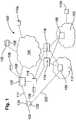
- a communication system 100including a packet switched network 104 and circuit switched networks 112 and 120.
- the packet switched network 104may be the internet. Data may be transmitted via the internet 104 via a peer to peer system.
- the circuit switched networks 112, 120may be PSTN (Public Switched Telephone Network) networks.
- a user device 102is shown to be connected to the internet 104 via a session node 106.
- the user device 102is also connected to the PSTN network 120.
- the user deviceis connected to the PSTN network 112 via a circuit switched connection 222 and to the session node 106 via a packet switched connection 111.
- the circuit switched connection 222 and the packet switched connection 111may be provided by a GSM (Global System for Mobile Communications) network (not shown).
- the packet switched connectionmay be provided by a GPRS (General Packet Radio Service) connection of the GSM network whilst the circuit switched connection may be provided by a GSM audio connection of the GSM network.
- the packet switched connection 111is used to transmit packet data according to an internet protocol such as Transmission Control Protocol (TCP).
- TCPTransmission Control Protocol
- the user device 102may be, for example, a personal computer, a gaming device, a personal digital assistant, a suitably enabled mobile phone, or other device able to connect to the network 104.
- the session node 106runs a communication instance 122 defining a session dedicated to a user of the user device 102.
- the communication instance 122enables the user of the user device 102 to communicate across the communication system 100.
- the session node 106is able to concurrently run a plurality of communication instances for a number of other users operating other user devices (not shown).
- the user device 102runs a client software program 124 that provides a client interface on the user device and allows the user of the user device 102 to communicate with the communication instance 122 running on the session node 106.
- the client program 124 running on the user devicehas a number of different components or layers for implementing various functions, including a protocol layer 402 ( Figure 2a ) for managing the interface with the GSM network .
- a protocol layer 402Figure 2a
- the interface with the GSM networkwill be described hereinafter with reference to Figure 2b .
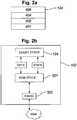
- FIG. 2ashows a protocol stack for the client program 124 according to an embodiment of the present invention.
- the protocol stackshows an operating system layer 401, a protocol layer 402, a client engine layer 404 and a client user interface layer 406.
- Each layeris responsible for specific functions. Because each layer usually communicates with two other layers, they are regarded as being arranged in a stack as shown in figure 2a .
- the operating system layer 401manages the hardware resources of the user device 102 and handles data being transmitted to and from the session node 106.
- the operating system layeralso handles the data being transmitted to and from the network 112.
- the client protocol layer 402 of the client softwarecommunicates with the operating system 401. Processes requiring higher level processing are passed to the client engine layer 404.
- the client engine 404also communicates with the user client user interface layer 406.
- the client enginemay be arranged to control the client user interface layer 406 to present information to the user via user interface means of the user device and to receive information from the user via the user interface means of the user device.
- the user interface meansmay comprise a speaker, a microphone, a display screen and a keyboard. This list is not exhaustive.
- FIG 2bis a schematic diagram showing the transmission of data between the client protocol stack and the GSM protocol stack in the user device 102.
- the user device 102further comprises a GSM protocol stack 501 and a radio transceiver 502.
- Information transmitted from the GSM network to the user deviceis received by the transceiver 502.
- the data received from the GSM networkis processed by GSM protocol stack 501 before it is transmitted to the client program 124.
- information to be transmitted to the GSM network from the client program 124is processed by the GSM protocol stack 501 before it is transmitted to the GSM network via the transceiver 502.
- the operation of the GSM protocol stack 501is known in the art and will not be described in detail herein.
- the peer to peer system on the internet 104comprises an inbound gateway 114 and an outbound gateway 116.
- the inbound gateway 114 and the outbound gateway 116are connected to PSTN gateways 188 located in the PSTN networks.
- the inbound gateway 114is arranged to receive data for the peer to peer system on the internet 104 from the PSTN gateways 188.
- the outbound gateway 116is arranged to transmit data from the peer to peer system on the internet 104 to the to the PSTN gateways 188.
- the profile node 128is responsible for storing user profile information for users of the peer to peer system.
- the user profile informationincludes login information for logging into the peer to peer system and a contact list 132 associated with each user of the peer to peer system.
- the contact list 132comprises the addresses of, for example, other users of the communication system stored as contacts by a user.
- the communication instance 122 running on the session node 106manages the communication between the client program 124 running on the device 102 and the peer to peer system on the internet 104.
- Figure 3shows the connection path between the communication instance 122 on the session node 106 and the client program 124 running on the user device 102.
- the session node 106further comprises a core module 205 for allocating a communication instance 122 to a client program 124.
- the client program 124 running on the user device 102is arranged to set up a connection with the session node 106.
- the client program 124sends the session node 106 data relating to the user device 102 via the packet switched connection 111 in a data packet.
- the data packetmay include the attributes listed in table 1: Table 1: KEY TYPE ATTRIBUTE CHUNKTYPE integer CLIENTDATA DEVICE_PSTNNUMBER string device PSTN number in international notation.
- the data packetincludes an attribute defining an IP address of the user device and an attribute defining a PSTN number of the device.
- the PSTN addressidentifies the user device 102 in the PSTN network 112.
- the user of the user devicemay then provide login information to the session node 106 in order to log into the peer to peer system on the internet 104.
- the session nodemay verify the login information provided from the user device against the profile information for the user of the user device 102 stored on the profile node 128. On verification of the login information provided from the user device 102 the core module 205 will assign a dedicated communication instance 122 to the client program 124.
- the communication instance 122associates the identity user of the user device as defined by at least part of the login details of the user with the identity of the device as defined by the PSTN number of the device.
- the communication instancemay store the identity of the user together with the identity of the user device in a data store 129 associated with the communication instance.
- the user of the user devicemay log into the peer to peer system using more than one user device.
- the communication instancewill associate the identity of each device with the identity of the user in the peer to peer system.
- the communication instance 122will provide the client program 124 with data to enable to the client program to establish a communication event with an entity in the communication system 100.
- the entitymay be any node in the communication system 100 that is capable of transmitting information to the user device 102.
- the entitymay be another user device or a network node in the communication system 100.
- the entitymay correspond to voice mail records, or other data records associated with the user of the user device.
- the entitymay be an entity arranged to instruct the client program to carry out control commands.
- Ah entityis located by an address in the network in which it resides.
- the address of an entity that resides in the internet 104may be for example an IP address, a URI (Uniform Resource Indicator), a username, of a VoIP device.
- the address of an entity that resides in the PSTN networkmay be a PSTN number associated with the entity.
- the entitymay be located in more than one network.
- the entitymay be a user that is logged into the peer to peer system of the internet using two or more user devices. In this case an entity will have more than one associated addresses.
- the user device 102may transmit or receive a communication event with an entity via more than one network of the communication system. For example the user device 102 may receive a call via the PSTN network 112 from an entity located in the internet 104.
- the communication instance 122is arranged to allocate an entity an identity that may be transmitted and interpreted by both the PSTN network and the peer to peer system on the internet.
- the identity of the entitymay be resolved to the address of the entity by a node located in the internet 104.
- the allocated identityis a PSTN number.
- the communication instance 122is arranged to allocate a PSTN number to the entity that may be used to identify the entity during a call with the entity via the PSTN network.
- a call manager 118is connected to the session node 106, the inbound gateway 114 and the outbound gateway 116.
- the call managerhas access to the data store 126.
- the data store 126is shown as being associated with the call manager 118. In an alternative embodiment of the invention the data store 126 may be associated with the call session node 106.
- the call manager 118is shown as being located separately from the session node 106 and the gateways 114 and 116. In alternative embodiments the call manager 118 may however form part of either the session node 106 or of one of the gateways 114 or 116.
- the logical connections between the call manager, the session node, the inbound gateway and the outbound gatewayare shown in Figure 6 .
- the call manager 118is arranged to provide the communication instance 122 with a PSTN number to be allocated to an entity in response to a request from the communication instance.
- the communication instanceis arranged to allocate the PSTN number to the entity and to provide the address of the entity to the call manager.
- the call manageris then arranged to store the allocated PSTN number in the data store 126 together with the address of the entity.
- the address of an entityis determined from the contact list 132 provided from the profile node 128. This embodiment of the invention will be described with reference to Figure 4 .
- Figure 4is a diagram showing the steps for allocating a PSTN number to an entity in accordance with a preferred embodiment of the invention.
- step S1the communication instance 122 is arranged to retrieve the addresses of the entities of that are listed as contacts in the contact list 132 associated with the user of the user device 102.
- the addresses of the entitiesare retrieved from the profile node 128.
- step S2the communication instance stores the address of each entity in the data store 129.
- the entire contact list 132is stored in the data store 129.
- step S3the communication instance 122 is then arranged to retrieve a PSTN number for each entity listed in the contact list from the call manager.
- step S4the communication instance is arranged to allocate each PSTN number to each entity listed in the contact list and to report the addresses of each entity allocated a PSTN number to the call manager.
- step S5the call manager 118 is arranged to store in the data store 126 a PSTN number in association with the address for each entity listed in the contact list.
- the call manageris arranged to additionally store in the data store 126 the PSTN number of the user device 102 in association with the PSTN number allocated to the entity.
- the PSTN number of the user devicemay be reported to the call manager in either step S3 or step S4.
- the address of the entitymay be resolved using the PSTN number allocated to the entity and the PSTN number of the device. In this case one PSTN number may be allocated for use by more than one user.
- the contact list 132 together with the PSTN numbers allocated to each entity in the contact listare transmitted from the communication instance to the client program 124.
- the allocated PSTN numbers and the contact list 132are transmitted to the client program 124 in data packets via the data connection 111.
- the allocated PSTN numbersmay be provided in a separate data packet from the contact list 132.
- At least part of the PSTN numbersmay be provided to the client program in a 'call set up' data packet comprising the attributes listed in table 2: Table 2 KEY TYPE ATTRIBUTE CHUNKTYPE integer CALLSETUP CALLMETHOD integer a numeric value identifying calling method to use DIALIN_NUMBER_PREFIX string first number in dial-in number range, for example " +3725521000 " DIALIN_NUMBER_RANGE_SIZE integer # of numbers in dial-in block, for example 1000 VOICEMAIL_NUMBER_PREFIX string dial-in number range for listening voicemails VOICEMAIL_NUMBER_RANGE_SIZE integer # of numbers in voicemail number block
- each PSTN number for calling an entitymay be listed separately in the data packet.
- each PSTN numbermay be determined by the client program 124 from a first number and a second number corresponding to an index number identifying the contact in the contact list (see table 3).
- the range of indexesmay be limited by of a number range defined in the data packet, as shown in table 2.
- Table 3shows the attributes of the data packet containing the contact list 132. Each entity in the contact list is given an index value starting from 1.
- the attribute container containing the contact listmay further include the contacts username, or URI for contacting the contact using the peer to peer system, and the name of the contact.
- Table 3KEY TYPE ATTRIBUTE CHUNKTYPE integer CONTACT CONTACTINDEX integer contact index value, starting from 1 SKYPENAME string contact username FULLNAME string PSTNNUMBER string
- the client program 124may determine the PSTN number by arithmetically adding the first number to the second number. For example if the first number is defined as: +3725521020 and the second number, corresponding to an index, is: 33 the PSTN number for the contact identified by index 33will be: +3725521053
- the client programmay determine the PSTN number by appending the second number corresponding to a member of the number range to the first number. For example, if the first number is: +37255210 and the index corresponding to the entity is: 33 the PSTN number will be: +3725521033
- the call method attribute referred to in table 2may indicate how the PSTN number should be determined from the information provided in the data packet.
- the call methodmay specify whether the PSTN number should be determined by arithmetically adding the member of the number range to the first number, or by appending the member of the number range to the first number, or whether the entire PSTN number is listed in the data packet.
- the communication instance 122is arranged to send the contact list 132 to the client program 124.
- the client program 124may generate a PSTN number for each contract having an index.
- the client programmay determine which PSTN number corresponds to which entity by correlating the position of a PSTN number in the list with the index number provided for each entity in the contact list.
- a predefined PSTN number, or indexis reserved for communication events that occur with entities that are not listed in the contact list.
- the index '0'is reserved for entities that are not listed on the contact list.
- other numbersmay be reserved for transmitting control commands from the network 104 to the client program 124. This will be described in more detail hereinafter.
- the user device 102may receive calls from an entity located in the communication network via the PSTN network.
- the user device 102may also establish a call to an entity located in the communication network 100 via the PSTN network using the PSTN number allocated to the entity.
- Figure 5shows the call connections made when placing calls between the user device 102 and entities located in the communication network. More specifically Figure 6 shows the following call connections:
- inbound calls made to the client running on the user device 102are routed to the session node 106 from the calling entity.
- the session node 106is then able to determine the PSTN number of the device and the PSTN number allocated to the entity by querying the data store 126.
- the method of receiving a call at the user device 102will now be describe in detail in relation to Figure 7 .
- FIG 7is a diagram illustrating the reception of a call at the user device 102.
- the control data connection for handling the call set up and the media data connection for transmitting the media dataare shown separately.
- the control data connectionis shown as a solid line and the media data connection is shown as a broken line.
- the callmay originate from an entity located in the packet switched network 104 or from an entity located in the circuit switched network 112. The following method will be described the case where a call is initiated from an entity located in the internet 104.
- step S10an incoming call from the packet switched network 104 is received at the communication instance 122 running on the session node 106.
- the control data of the incoming callwill identify the destination of the call with the username associated with user of the user device 102.
- the username of the useris used to locate the communication instance 122 in the peer to peer system on the internet 104.
- the control datamay also identify the origin of the call by including username of the calling entity.
- step S20the communication instance searches the data store 129 to determine the PSTN number of the device 102.
- the communication instancemay also search the contact list 132 associated with the user of the device 102 to determine if the username of the calling entity matches an entity listed in the contact list 132. If calling entity is listed in the contact list 132, the PSTN number allocated to the calling entity will be retrieved from the data store 129. If the calling entity is not listed in the contact list the PSTN number reserved for entities not listed on the contact list will be retrieved.
- step S30the control data connection comprising the PSTN number of the device 102 is transmitted, together with the media data connection, to the outbound gateway 116.
- the control datamay also include the PSTN number retrieved from the data store 129 to identify the calling entity.
- step 40the call is transmitted from the outbound gateway 116 to the PSTN gateway 188 using the PSTN number of the device.
- the PSTN number retrieved from the data store 129 to identify the calling entityis also transmitted with the call.
- step S50the call is transmitted to the user device 102 via the PSTN network.
- the PSTN number retrieved to identify the calling entityis recognised by the PSTN network and may be transmitted by the PSTN network to identify the origin of the call.
- step S60the client program 124 running on the user device 102 is arranged to resolve the allocated PSTN number to the associated contact details of the entity provided in the contact list 132. This may be achieved by mapping the PSTN number of the calling entity to the username of the contact using the mapping method described previously. For example if the PSTN number associated with the calling entity is generated at the client program 124 using the index representing the entity, the client program may be arranged to subtract the first number from the PSTN number to derive the index and identify the contact. The username of the contact may then be displayed on the display of the user device to show that there is an incoming call from that contact.
- the client program 124may be arranged to display the predefined text on the display of the user device which states that the caller is 'unknown'.
- the media data connectionis not established via the communication instance 122 as shown in Figure 7 . Instead steps S10 to S30 may be used to set up the control data connection only. The media data connection may then be established between the outbound gateway and the calling entity after the control data connection is established.
- the identity calling entity in the peer to peer systemmay be arranged to transmit a command to be carried out by the client program 124.
- the commandmay for example relate to an instruction for the client program 124 to establish a connection with the session node 106.
- the commandmay originate either from another node located in the network 104 or from the session node 106. This embodiment of the invention will be described in relation to Figure 8 .
- step S101the node 166 transmitting the communication event comprising the command is arranged to address the communication event to the username of the user of the device 102.
- the commandis identified as the caller identity of communication event.
- step S102the communication instance receives the communication event.
- the communication instanceis arranged to search the data store 129 to retrieve a PSTN number corresponding to the command listed in the contact list 132. Additionally the communication instance is arranged to retrieve the PSTN number of the user device associated with the username.
- step S103the communication event is routed to the user device 102 via the PSTN network using the PSTN number of the user device 102.
- the PSTN number allocated to the commandis transmitted with the communication event as the caller identity of the communication event.
- step S104the client program is arranged to resolve the caller identity of the communication event to the command listed in the contact list.
- the client programis then arranged to carry out the command. For example, if the command is 'connect' the client program will establish a connection with the session node 106.
Landscapes
- Engineering & Computer Science (AREA)
- Computer Networks & Wireless Communication (AREA)
- Signal Processing (AREA)
- Multimedia (AREA)
- Business, Economics & Management (AREA)
- General Business, Economics & Management (AREA)
- Computer Hardware Design (AREA)
- General Engineering & Computer Science (AREA)
- Computing Systems (AREA)
- Computer Security & Cryptography (AREA)
- Data Exchanges In Wide-Area Networks (AREA)
- Telephonic Communication Services (AREA)
- Mobile Radio Communication Systems (AREA)
- Computer And Data Communications (AREA)
Description
- The present invention relates to a method for handling communication in a communication system.
- Communication systems link together two communication devices so that the devices can send information to each other in a call or other communication event. Information may include voice, text, images or video.
- One such communication system is a peer to peer system, in which a plurality of end users can be connected for communication purposes via a communications structure such as the internet. The communications structure is substantially decentralised with regard to communication route switching therein for connecting the end users. That is, the end users can establish their own communication routes through the structure based on exchange of one or more authorisation certificates (user identity certificates - UIC) to acquire access to the structure. The structure includes an administration arrangement issuing the certificates to the end users. Such a communication system is described in
WO 2005/009019 . - Peer-to-peer systems and other communication systems that use the internet or any other packet switched network employ voice over IP (internet protocol) protocols (VoIP) to transmit data. These systems are commonly referred to as VoIP systems. VoIP systems are beneficial to the user as they are often of significantly lower cost than communication networks, such as fixed line or mobile networks, otherwise referred to as public switched telephone networks (PSTN). This may particularly be the case for long distance calls.
- The connection of two communication devices using more than one type of network is becoming increasingly common. In some cases a call may be transmitted via more than one network in an attempt to reduce the cost of the call. For example a call between two devices located in a PSTN network may be transmitted via the internet. In other cases it is necessary to transmit the call via two networks when each device is located in a different network.
- Gateways are provided at the interface between different networks to translate call data from a form required by a protocol of one network into a form required by a protocol of another network. However in some cases some data associated with the call may not be supported by the protocol of one of networks. In this case the data associated with the call is lost.
- For example a communication device such as a mobile phone located in a PSTN network may be arranged to identify the origin of an incoming call. However if the call has originated from a device located in the internet the PSTN network cannot recognise and transmit the identity of user of the device to the mobile phone. As such the identity of the calling party will be lost.
WO02/076049 WO01/39469 - It is therefore an aim of embodiments of the invention to address at least one of the above identified problems.
- According to a first aspect of the invention there is provided a method according to
independent claim 1. - According to a second aspect of the present invention there is provided a network node according to independent claim 13.
- According to a third aspect of the present invention there is provided a receiving device according to independent claim 14.
- For a better understanding of the present invention and as to how the same may be carried into effect, embodiments of the present invention will now be described by way of example only with reference to the following drawings:
Figure 1 is a schematic representation of a communication system in accordance with an embodiment of the invention;Figure 2a is a diagram showing the protocol stack of a client program in accordance with an embodiment of the present invention;Figure 2b is a schematic diagram showing the transmission, of data between the client protocol stack and the GSM protocol stack in a user device in accordance with an embodiment of the present invention;Figure 3 is a schematic representation of part of the communication system shown inFigure 1 ;Figure 4 is a schematic representation of part of the communication system shown inFigure 1 according to an embodiment of the present invention;Figure 5 shows the call connections made when placing calls between a user device and entities located in the communication system according to an embodiment of the present invention;Figure 6 shows the logical connections between a call manager, a session node, an inbound gateway and an outbound gateway according to an embodiment of the present invention; andFigure 7 is a diagram showing the reception of a call in accordance with an embodiment of the present invention.Figure 8 is a diagram showing the reception of a command in accordance with an alternative embodiment of the present invention.- Reference will first be made to
Figure 1 , in which is shown acommunication system 100, including a packet switchednetwork 104 and circuit switchednetworks network 104 may be the internet. Data may be transmitted via theinternet 104 via a peer to peer system. The circuit switchednetworks - A
user device 102 is shown to be connected to theinternet 104 via asession node 106. Theuser device 102 is also connected to thePSTN network 120. In one embodiment of the invention the user device is connected to thePSTN network 112 via a circuit switchedconnection 222 and to thesession node 106 via a packet switchedconnection 111. The circuit switchedconnection 222 and the packet switchedconnection 111 may be provided by a GSM (Global System for Mobile Communications) network (not shown). For example the packet switched connection may be provided by a GPRS (General Packet Radio Service) connection of the GSM network whilst the circuit switched connection may be provided by a GSM audio connection of the GSM network. In a preferred embodiment of the invention the packet switchedconnection 111 is used to transmit packet data according to an internet protocol such as Transmission Control Protocol (TCP). - The
user device 102 may be, for example, a personal computer, a gaming device, a personal digital assistant, a suitably enabled mobile phone, or other device able to connect to thenetwork 104. - In accordance with an embodiment of the invention the
session node 106 runs acommunication instance 122 defining a session dedicated to a user of theuser device 102. Thecommunication instance 122 enables the user of theuser device 102 to communicate across thecommunication system 100. Thesession node 106 is able to concurrently run a plurality of communication instances for a number of other users operating other user devices (not shown). - The
user device 102 runs aclient software program 124 that provides a client interface on the user device and allows the user of theuser device 102 to communicate with thecommunication instance 122 running on thesession node 106. - The
client program 124 running on the user device has a number of different components or layers for implementing various functions, including a protocol layer 402 (Figure 2a ) for managing the interface with the GSM network . The interface with the GSM network will be described hereinafter with reference toFigure 2b . Figure 2a shows a protocol stack for theclient program 124 according to an embodiment of the present invention. The protocol stack shows anoperating system layer 401, aprotocol layer 402, aclient engine layer 404 and a clientuser interface layer 406. Each layer is responsible for specific functions. Because each layer usually communicates with two other layers, they are regarded as being arranged in a stack as shown infigure 2a . Theoperating system layer 401 manages the hardware resources of theuser device 102 and handles data being transmitted to and from thesession node 106. The operating system layer also handles the data being transmitted to and from thenetwork 112. Theclient protocol layer 402 of the client software communicates with theoperating system 401. Processes requiring higher level processing are passed to theclient engine layer 404. Theclient engine 404 also communicates with the user clientuser interface layer 406. The client engine may be arranged to control the clientuser interface layer 406 to present information to the user via user interface means of the user device and to receive information from the user via the user interface means of the user device. The user interface means may comprise a speaker, a microphone, a display screen and a keyboard. This list is not exhaustive.Figure 2b is a schematic diagram showing the transmission of data between the client protocol stack and the GSM protocol stack in theuser device 102. As shown inFigure 2b theuser device 102 further comprises aGSM protocol stack 501 and aradio transceiver 502. Information transmitted from the GSM network to the user device is received by thetransceiver 502. The data received from the GSM network is processed byGSM protocol stack 501 before it is transmitted to theclient program 124. Similarly, information to be transmitted to the GSM network from theclient program 124 is processed by theGSM protocol stack 501 before it is transmitted to the GSM network via thetransceiver 502. The operation of theGSM protocol stack 501 is known in the art and will not be described in detail herein.- Reference is again made to
Figure 1 . As shown inFigure 1 the peer to peer system on theinternet 104 comprises aninbound gateway 114 and anoutbound gateway 116. Theinbound gateway 114 and theoutbound gateway 116 are connected toPSTN gateways 188 located in the PSTN networks. Theinbound gateway 114 is arranged to receive data for the peer to peer system on theinternet 104 from thePSTN gateways 188. Theoutbound gateway 116 is arranged to transmit data from the peer to peer system on theinternet 104 to the to thePSTN gateways 188. - Also shown in
Figure 1 is aprofile node 128. Theprofile node 128 is responsible for storing user profile information for users of the peer to peer system. The user profile information includes login information for logging into the peer to peer system and acontact list 132 associated with each user of the peer to peer system. Thecontact list 132 comprises the addresses of, for example, other users of the communication system stored as contacts by a user. - The
communication instance 122 running on thesession node 106 manages the communication between theclient program 124 running on thedevice 102 and the peer to peer system on theinternet 104.Figure 3 shows the connection path between thecommunication instance 122 on thesession node 106 and theclient program 124 running on theuser device 102. As shown inFigure 3 , thesession node 106 further comprises acore module 205 for allocating acommunication instance 122 to aclient program 124. - In accordance with an embodiment of the invention the
client program 124 running on theuser device 102 is arranged to set up a connection with thesession node 106. Theclient program 124 sends thesession node 106 data relating to theuser device 102 via the packet switchedconnection 111 in a data packet. The data packet may include the attributes listed in table 1:Table 1: KEY TYPE ATTRIBUTE CHUNKTYPE integer CLIENTDATA DEVICE_PSTNNUMBER string device PSTN number in international notation. - As shown in table 1, the data packet includes an attribute defining an IP address of the user device and an attribute defining a PSTN number of the device. The PSTN address identifies the
user device 102 in thePSTN network 112. - After a connection between the
client program 124 and thesession node 106 has been established the user of the user device may then provide login information to thesession node 106 in order to log into the peer to peer system on theinternet 104. - The session node may verify the login information provided from the user device against the profile information for the user of the
user device 102 stored on theprofile node 128. On verification of the login information provided from theuser device 102 thecore module 205 will assign adedicated communication instance 122 to theclient program 124. - The
communication instance 122 associates the identity user of the user device as defined by at least part of the login details of the user with the identity of the device as defined by the PSTN number of the device. In one embodiment of the invention the communication instance may store the identity of the user together with the identity of the user device in adata store 129 associated with the communication instance. - According to an embodiment of the invention it is possible for the user of the user device to log into the peer to peer system using more than one user device. According to this embodiment of the invention the communication instance will associate the identity of each device with the identity of the user in the peer to peer system.
- Once the
session node 106 has assigned acommunication instance 122 to theuser device 102 thecommunication instance 122 will provide theclient program 124 with data to enable to the client program to establish a communication event with an entity in thecommunication system 100. - The entity may be any node in the
communication system 100 that is capable of transmitting information to theuser device 102. For example the entity may be another user device or a network node in thecommunication system 100. The entity may correspond to voice mail records, or other data records associated with the user of the user device. Additionally the entity may be an entity arranged to instruct the client program to carry out control commands. - Ah entity is located by an address in the network in which it resides. The address of an entity that resides in the
internet 104 may be for example an IP address, a URI (Uniform Resource Indicator), a username, of a VoIP device. The address of an entity that resides in the PSTN network may be a PSTN number associated with the entity. - In one embodiment of the invention the entity may be located in more than one network. For example the entity may be a user that is logged into the peer to peer system of the internet using two or more user devices. In this case an entity will have more than one associated addresses.
- The
user device 102 may transmit or receive a communication event with an entity via more than one network of the communication system. For example theuser device 102 may receive a call via thePSTN network 112 from an entity located in theinternet 104. - In accordance with an embodiment of the invention the
communication instance 122 is arranged to allocate an entity an identity that may be transmitted and interpreted by both the PSTN network and the peer to peer system on the internet. In this case the identity of the entity may be resolved to the address of the entity by a node located in theinternet 104. In a preferred embodiment of the invention the allocated identity is a PSTN number. - For example, if the entity is located in the internet, the IP address of the entity the will not be recognized by the PSTN network. The
communication instance 122 is arranged to allocate a PSTN number to the entity that may be used to identify the entity during a call with the entity via the PSTN network. - As shown in
Figure 1 acall manager 118 is connected to thesession node 106, theinbound gateway 114 and theoutbound gateway 116. The call manager has access to thedata store 126. InFigure 1 thedata store 126 is shown as being associated with thecall manager 118. In an alternative embodiment of the invention thedata store 126 may be associated with thecall session node 106. - In the embodiment shown in
Figure 1 thecall manager 118 is shown as being located separately from thesession node 106 and thegateways call manager 118 may however form part of either thesession node 106 or of one of thegateways Figure 6 . - The
call manager 118 is arranged to provide thecommunication instance 122 with a PSTN number to be allocated to an entity in response to a request from the communication instance. The communication instance is arranged to allocate the PSTN number to the entity and to provide the address of the entity to the call manager. The call manager is then arranged to store the allocated PSTN number in thedata store 126 together with the address of the entity. - In a preferred embodiment of the invention the address of an entity is determined from the
contact list 132 provided from theprofile node 128. This embodiment of the invention will be described with reference toFigure 4 . Figure 4 is a diagram showing the steps for allocating a PSTN number to an entity in accordance with a preferred embodiment of the invention.- In step S1 the
communication instance 122 is arranged to retrieve the addresses of the entities of that are listed as contacts in thecontact list 132 associated with the user of theuser device 102. The addresses of the entities are retrieved from theprofile node 128. - In step S2 the communication instance stores the address of each entity in the
data store 129. In a preferred embodiment of the invention theentire contact list 132 is stored in thedata store 129. - In step S3 the
communication instance 122 is then arranged to retrieve a PSTN number for each entity listed in the contact list from the call manager. - In step S4 the communication instance is arranged to allocate each PSTN number to each entity listed in the contact list and to report the addresses of each entity allocated a PSTN number to the call manager.
- In step S5 the
call manager 118 is arranged to store in the data store 126 a PSTN number in association with the address for each entity listed in the contact list. - In one embodiment of the invention the call manager is arranged to additionally store in the
data store 126 the PSTN number of theuser device 102 in association with the PSTN number allocated to the entity. The PSTN number of the user device may be reported to the call manager in either step S3 or step S4. In this embodiment of the invention the address of the entity may be resolved using the PSTN number allocated to the entity and the PSTN number of the device. In this case one PSTN number may be allocated for use by more than one user. - The
contact list 132 together with the PSTN numbers allocated to each entity in the contact list are transmitted from the communication instance to theclient program 124. - In a preferred embodiment of the invention the allocated PSTN numbers and the
contact list 132 are transmitted to theclient program 124 in data packets via thedata connection 111. The allocated PSTN numbers may be provided in a separate data packet from thecontact list 132. - At least part of the PSTN numbers may be provided to the client program in a 'call set up' data packet comprising the attributes listed in table 2:
Table 2 KEY TYPE ATTRIBUTE CHUNKTYPE integer CALLSETUP CALLMETHOD integer a numeric value identifying calling method to use DIALIN_NUMBER_PREFIX string first number in dial-in number range, for example "+3725521000" DIALIN_NUMBER_RANGE_SIZE integer # of numbers in dial-in block, for example 1000 VOICEMAIL_NUMBER_PREFIX string dial-in number range for listening voicemails VOICEMAIL_NUMBER_RANGE_SIZE integer # of numbers in voicemail number block - In one embodiment of the invention each PSTN number for calling an entity may be listed separately in the data packet. However in a preferred embodiment, each PSTN number may be determined by the
client program 124 from a first number and a second number corresponding to an index number identifying the contact in the contact list (see table 3). The range of indexes may be limited by of a number range defined in the data packet, as shown in table 2. - Table 3 shows the attributes of the data packet containing the
contact list 132. Each entity in the contact list is given an index value starting from 1. The attribute container containing the contact list may further include the contacts username, or URI for contacting the contact using the peer to peer system, and the name of the contact.Table 3: KEY TYPE ATTRIBUTE CHUNKTYPE integer CONTACT CONTACTINDEX integer contact index value, starting from 1 SKYPENAME string contact username FULLNAME string PSTNNUMBER string - The
client program 124 may determine the PSTN number by arithmetically adding the first number to the second number. For example if the first number is defined as:
+3725521020
and the second number, corresponding to an index, is:
33
the PSTN number for the contact identified by index 33will be:
+3725521053 - Alternatively the client program may determine the PSTN number by appending the second number corresponding to a member of the number range to the first number. For example, if the first number is:
+37255210
and the index corresponding to the entity is:
33
the PSTN number will be:
+3725521033 - In one embodiment of the invention the call method attribute referred to in table 2 may indicate how the PSTN number should be determined from the information provided in the data packet. For example, the call method may specify whether the PSTN number should be determined by arithmetically adding the member of the number range to the first number, or by appending the member of the number range to the first number, or whether the entire PSTN number is listed in the data packet.
- The
communication instance 122 is arranged to send thecontact list 132 to theclient program 124. In the case where the call method requires that part of the PSTN number is derived using the index of the contract, theclient program 124 may generate a PSTN number for each contract having an index. In the case where the call method indicates that a list of entire PSTN numbers are provided in the call set up data packet the client program may determine which PSTN number corresponds to which entity by correlating the position of a PSTN number in the list with the index number provided for each entity in the contact list. - In an embodiment of the invention a predefined PSTN number, or index, is reserved for communication events that occur with entities that are not listed in the contact list. In a preferred embodiment of the invention the index '0' is reserved for entities that are not listed on the contact list. Additionally, other numbers may be reserved for transmitting control commands from the
network 104 to theclient program 124. This will be described in more detail hereinafter. - In accordance with an embodiment of the invention the
user device 102 may receive calls from an entity located in the communication network via the PSTN network. Theuser device 102 may also establish a call to an entity located in thecommunication network 100 via the PSTN network using the PSTN number allocated to the entity. Figure 5 shows the call connections made when placing calls between theuser device 102 and entities located in the communication network. More specificallyFigure 6 shows the following call connections:- (1) an outbound call from the
user device 102 to anentity 110b located in the PSTN network; - (2) an outbound call from the
user device 102 to anentity 110a located in theinternet 104; - (3) an inbound call to the
user device 102 from anentity 110b located in the PSTN network; and - (4) an inbound call to the
user device 102 from anentity 110a located in the PSTN network. - As shown in
Figure 5 , inbound calls made to the client running on theuser device 102 are routed to thesession node 106 from the calling entity. Thesession node 106 is then able to determine the PSTN number of the device and the PSTN number allocated to the entity by querying thedata store 126. The method of receiving a call at theuser device 102 will now be describe in detail in relation toFigure 7 . Figure 7 is a diagram illustrating the reception of a call at theuser device 102. InFigure 7 the control data connection for handling the call set up and the media data connection for transmitting the media data are shown separately. The control data connection is shown as a solid line and the media data connection is shown as a broken line.- The call may originate from an entity located in the packet switched
network 104 or from an entity located in the circuit switchednetwork 112. The following method will be described the case where a call is initiated from an entity located in theinternet 104. - In step S10, an incoming call from the packet switched
network 104 is received at thecommunication instance 122 running on thesession node 106. The control data of the incoming call will identify the destination of the call with the username associated with user of theuser device 102. The username of the user is used to locate thecommunication instance 122 in the peer to peer system on theinternet 104. The control data may also identify the origin of the call by including username of the calling entity. - In step S20 the communication instance searches the
data store 129 to determine the PSTN number of thedevice 102. The communication instance may also search thecontact list 132 associated with the user of thedevice 102 to determine if the username of the calling entity matches an entity listed in thecontact list 132. If calling entity is listed in thecontact list 132, the PSTN number allocated to the calling entity will be retrieved from thedata store 129. If the calling entity is not listed in the contact list the PSTN number reserved for entities not listed on the contact list will be retrieved. - In step S30, the control data connection comprising the PSTN number of the
device 102 is transmitted, together with the media data connection, to theoutbound gateway 116. The control data may also include the PSTN number retrieved from thedata store 129 to identify the calling entity. - In
step 40 the call is transmitted from theoutbound gateway 116 to thePSTN gateway 188 using the PSTN number of the device. The PSTN number retrieved from thedata store 129 to identify the calling entity is also transmitted with the call. - In step S50 the call is transmitted to the
user device 102 via the PSTN network. The PSTN number retrieved to identify the calling entity is recognised by the PSTN network and may be transmitted by the PSTN network to identify the origin of the call. - If the calling entity has an allocated PSTN number, in step S60 the
client program 124 running on theuser device 102 is arranged to resolve the allocated PSTN number to the associated contact details of the entity provided in thecontact list 132. This may be achieved by mapping the PSTN number of the calling entity to the username of the contact using the mapping method described previously. For example if the PSTN number associated with the calling entity is generated at theclient program 124 using the index representing the entity, the client program may be arranged to subtract the first number from the PSTN number to derive the index and identify the contact. The username of the contact may then be displayed on the display of the user device to show that there is an incoming call from that contact. - Alternatively, if the reserved PSTN number was transmitted with the call to identify that the calling entity was not stored on the
contact list 132, theclient program 124 may be arranged to display the predefined text on the display of the user device which states that the caller is 'unknown'. - In an alternative embodiment of the invention the media data connection is not established via the
communication instance 122 as shown inFigure 7 . Instead steps S10 to S30 may be used to set up the control data connection only. The media data connection may then be established between the outbound gateway and the calling entity after the control data connection is established. - In an alternative embodiment of the invention the identity calling entity in the peer to peer system may be arranged to transmit a command to be carried out by the
client program 124. The command may for example relate to an instruction for theclient program 124 to establish a connection with thesession node 106. The command may originate either from another node located in thenetwork 104 or from thesession node 106. This embodiment of the invention will be described in relation toFigure 8 . - In step S101 the
node 166 transmitting the communication event comprising the command is arranged to address the communication event to the username of the user of thedevice 102. The command is identified as the caller identity of communication event. - In step S102 the communication instance receives the communication event. The communication instance is arranged to search the
data store 129 to retrieve a PSTN number corresponding to the command listed in thecontact list 132. Additionally the communication instance is arranged to retrieve the PSTN number of the user device associated with the username. - In step S103 the communication event is routed to the
user device 102 via the PSTN network using the PSTN number of theuser device 102. The PSTN number allocated to the command is transmitted with the communication event as the caller identity of the communication event. - In step S104 the client program is arranged to resolve the caller identity of the communication event to the command listed in the contact list. The client program is then arranged to carry out the command. For example, if the command is 'connect' the client program will establish a connection with the
session node 106. - While this invention has been particularly shown and described with reference to preferred embodiments, it will be understood to those skilled in the art that various changes in form and detail may be made without departing from the scope of the invention as defined by the claims.
Claims (15)
- A method of receiving a communication event from a calling entity located in a communication network (100) comprising a first network (120) and a second network (104), at a receiving device (102) associated with a user located in the communication system,characterised in that said method comprises the steps of:associating a first identity recognisable in the first network with a second identity recognisable in the second network for both the user and the calling entity at a data store (126,129) located in the second network;providing the first and second identities for the calling entity to the receiving device via the second network;receiving at a node (106) in the second network associated with the user, the communication event together with the second identity for the calling entity via the second network, wherein the communication event is addressed with the second identity of the user;querying the data store with the second identity of the calling entity and the second identity of the user to determine the first identity of the calling entity and the first identity of the user;receiving at the receiving device associated with the user the communication event together with the first identity for the calling entity via the first network, wherein the communication event is addressed with the first identity of the user; anddetermining the second identity of the calling entity at the receiving device associated with the user using the first identity of the calling entity.
- A method as claimed in claim 1 wherein the node in the second network associated with the user is arranged to communicate via a communication system operating on the second network on behalf of the user of the receiving device
- A method as claimed in claim 2 wherein the node associated with the user is arranged to log into the communication system operating on the second network on behalf of the user of the receiving device.
- A method as claimed in any preceding claim wherein the first identity and the second identity associated with the user are transmitted from the receiving device to the data store, optionally via the node associated with the user.
- A method as claimed in any preceding claim wherein the second identity of the calling entity is determined from a contact list (132) associated with the user of the receiving device, the contact list optionally defining a plurality of entities capable of establishing a communication event with the user device, and wherein one of said plurality of entities is said calling entity.
- A method as claimed in claim 5 wherein the step of providing the first and second identities for the calling entity to the receiving device comprises; providing a first identity recognisable in the first network and a second identity recognisable in the second network for each of said plurality of entities defined in the contact list, optionally in response to a request from the receiving device.
- A method as claimed in claims 6 wherein at least part of the first identities of the plurality of entities are provided to the receiving device in a first data packet.
- A method as claimed in claim 7 wherein the second identities of the plurality of entities are provided in a second data packet.
- A method as claimed in claim 8 wherein the step of determining the second identity using the first identity of the entity comprises;
selecting a second identity from the second identities provided in the second data packet using the first identity. - A method as claimed in any preceding claim wherein the communication event comprises an instruction to be carried out at the user device, the instruction optionally defined by the second identity of the calling entity.
- A method as claimed in any preceding claim wherein the calling entity is a user of the communication network.
- A method as claimed in claims 2 to 11 wherein the communication system operating on the second network is a peer to peer system.
- A network node (106) for receiving a communication event for a user of a communication network (100) from a calling entity, said communication network comprising a first network (120) and a second network (104),characterised in that said network node executes a communication instance arranged to store at a data store (126, 129) a first identity recognisable in the first network in association with a second identity recognisable in the second network for both the user and the calling entity;
to transmit the first and second identities for the calling entity to a receiving device associated with the user via the second network;
to receive the communication event together with the second identity for the calling entity via the second network, wherein the communication event is addressed with the second identity of the user; and
to determine the first identity of the calling entity and the first identity of the user using the second identity of the calling entity and the second identity of the user;
wherein the communication instance is further arranged to transmit the communication event together with the first identity for the calling entity to the receiving device via the first network using the first identity of the user such that the receiving device may determine the second identity of the calling entity using the first identity of the calling device. - A receiving device associated with a user arranged to receive a communication event from a calling entity via a communication network (100) comprising a first network (120) and a second network (104),characterised in that said receiving device comprising;
a processor executing a client program (124) arranged to receive a first identity recognisable in the first network and a second identity recognisable in the second network for the calling entity from a network node (106) storing said first identity in association with the second identity at a data store (126, 129);
a receiver arranged to receive the communication event together with the first identity of the calling entity via the first network;
wherein the client program is further arranged to determine the second identity of the calling entity using the first identity of the calling entity received from the network node. - A receiving device as claimed in claim 14 wherein the second identity of the calling entity defines at lease one of (i) the contact details of the calling entity, and (ii) an instruction to be carried out by the client program.
Applications Claiming Priority (3)
| Application Number | Priority Date | Filing Date | Title |
|---|---|---|---|
| GBGB0623621.0AGB0623621D0 (en) | 2006-11-27 | 2006-11-27 | Communication system |
| GB0723118AGB2444815B (en) | 2006-11-27 | 2007-11-23 | Communication system |
| PCT/IB2007/004261WO2008065535A2 (en) | 2006-11-27 | 2007-11-27 | Communication system |
Publications (2)
| Publication Number | Publication Date |
|---|---|
| EP2087694A2 EP2087694A2 (en) | 2009-08-12 |
| EP2087694B1true EP2087694B1 (en) | 2019-01-02 |
Family
ID=37636577
Family Applications (6)
| Application Number | Title | Priority Date | Filing Date |
|---|---|---|---|
| EP07859298.7AActiveEP2090077B1 (en) | 2006-11-27 | 2007-11-27 | Communication system |
| EP07859316AWithdrawnEP2078410A2 (en) | 2006-11-27 | 2007-11-27 | Communication system |
| EP07859329AWithdrawnEP2087695A2 (en) | 2006-11-27 | 2007-11-27 | Communication system |
| EP07859289.6AActiveEP2074791B1 (en) | 2006-11-27 | 2007-11-27 | Communication system |
| EP07859299.5AActiveEP2087694B1 (en) | 2006-11-27 | 2007-11-27 | Communication system |
| EP07859288.8AActiveEP2077024B1 (en) | 2006-11-27 | 2007-11-27 | Communication system |
Family Applications Before (4)
| Application Number | Title | Priority Date | Filing Date |
|---|---|---|---|
| EP07859298.7AActiveEP2090077B1 (en) | 2006-11-27 | 2007-11-27 | Communication system |
| EP07859316AWithdrawnEP2078410A2 (en) | 2006-11-27 | 2007-11-27 | Communication system |
| EP07859329AWithdrawnEP2087695A2 (en) | 2006-11-27 | 2007-11-27 | Communication system |
| EP07859289.6AActiveEP2074791B1 (en) | 2006-11-27 | 2007-11-27 | Communication system |
Family Applications After (1)
| Application Number | Title | Priority Date | Filing Date |
|---|---|---|---|
| EP07859288.8AActiveEP2077024B1 (en) | 2006-11-27 | 2007-11-27 | Communication system |
Country Status (8)
| Country | Link |
|---|---|
| US (8) | US8320546B2 (en) |
| EP (6) | EP2090077B1 (en) |
| CN (4) | CN101543010B (en) |
| BR (1) | BRPI0719664A2 (en) |
| CA (1) | CA2671034C (en) |
| GB (7) | GB0623621D0 (en) |
| IL (2) | IL198600A (en) |
| WO (6) | WO2008065534A2 (en) |
Families Citing this family (13)
| Publication number | Priority date | Publication date | Assignee | Title |
|---|---|---|---|---|
| US2767466A (en)* | 1945-10-08 | 1956-10-23 | Rca Corp | Method of making metal cones for cathode ray tubes |
| JP4635983B2 (en)* | 2006-08-10 | 2011-02-23 | ソニー株式会社 | COMMUNICATION PROCESSING DEVICE, DATA COMMUNICATION SYSTEM AND METHOD, AND COMPUTER PROGRAM |
| GB2443889A (en) | 2006-11-20 | 2008-05-21 | Skype Ltd | Method and system for anonymous communication |
| GB0623621D0 (en)* | 2006-11-27 | 2007-01-03 | Skype Ltd | Communication system |
| GB0623622D0 (en)* | 2006-11-27 | 2007-01-03 | Skype Ltd | Communication system |
| GB2459158A (en)* | 2008-04-17 | 2009-10-21 | Skype Ltd | Initiating a call via an access network wherein access number availability is indicated based on information associated with a device. |
| US8140003B2 (en)* | 2008-07-23 | 2012-03-20 | Qualcomm Incorporated | Method and apparatus for supporting multi-hop communications in a peer to peer communication system |
| SG159399A1 (en)* | 2008-08-13 | 2010-03-30 | Smart Comm Inc | Message routing platform |
| US8660246B1 (en) | 2009-04-06 | 2014-02-25 | Wendell Brown | Method and apparatus for content presentation in association with a telephone call |
| WO2012089247A1 (en)* | 2010-12-29 | 2012-07-05 | Nokia Siemens Networks Oy | A method and apparatus for transmitting an identity |
| US8671204B2 (en)* | 2011-06-29 | 2014-03-11 | Qualcomm Incorporated | Cooperative sharing of subscriptions to a subscriber-based network among M2M devices |
| CN110580240B (en)* | 2019-09-10 | 2020-12-22 | 北京海益同展信息科技有限公司 | Peripheral device management method and device for electronic device, electronic device and medium |
| CN114615315A (en)* | 2022-03-22 | 2022-06-10 | 深圳壹账通创配科技有限公司 | Communication method, device, equipment and storage medium for online conversation |
Family Cites Families (65)
| Publication number | Priority date | Publication date | Assignee | Title |
|---|---|---|---|---|
| JPH044298Y2 (en)* | 1986-02-27 | 1992-02-07 | ||
| CA2129199C (en)* | 1994-07-29 | 1999-07-20 | Roger Y.M. Cheung | Method and apparatus for bridging wireless lan to a wired lan |
| US6061363A (en)* | 1997-12-01 | 2000-05-09 | Nortel Networks Corporation | Communications system with load sharing communications interface |
| WO1999067922A1 (en) | 1998-06-25 | 1999-12-29 | Mci Worldcom, Inc. | Method and system for multicasting call notifications |
| US6088433A (en)* | 1998-07-09 | 2000-07-11 | Sbc Technology Resources, Inc. | System and method for forwarding call from disconnected telephone number to new telephone number |
| US6810034B1 (en) | 1999-02-26 | 2004-10-26 | Avaya Technology Corp. | Automatic conversion of telephone number to internet protocol address |
| US7388953B2 (en) | 1999-09-24 | 2008-06-17 | Verizon Business Global Llc | Method and system for providing intelligent network control services in IP telephony |
| CN1415159A (en) | 1999-09-24 | 2003-04-30 | 戴尔帕德通讯公司 | Flexible communications system |
| KR100434485B1 (en)* | 1999-10-08 | 2004-06-05 | 삼성전자주식회사 | Photoresist stripper composition and method for stripping photoresist using the same |
| IL149821A0 (en) | 1999-11-26 | 2002-11-10 | Mobile Telephone Networks Prop | Communication method and system |
| AU4139201A (en) | 1999-12-01 | 2001-06-12 | Wireless Internet, Inc. | Improvements in remote call-to-action messaging |
| KR100404137B1 (en) | 2000-02-25 | 2003-11-01 | 신광섭 | Internet interconnection method and internet interconnection system thereof |
| FI109443B (en) | 2000-03-16 | 2002-07-31 | Nokia Corp | Updating subscriber data |
| US6765921B1 (en)* | 2000-06-28 | 2004-07-20 | Nortel Networks Limited | Communications network |
| AT500077B1 (en)* | 2000-07-20 | 2008-07-15 | Akg Acoustics Gmbh | POPPLE PROTECTION FOR MICROPHONES |
| US20020071424A1 (en) | 2000-12-12 | 2002-06-13 | Chiu King W. | Packet voice telephony apparatus and method |
| WO2002057917A2 (en)* | 2001-01-22 | 2002-07-25 | Sun Microsystems, Inc. | Peer-to-peer network computing platform |
| US7043644B2 (en)* | 2001-01-31 | 2006-05-09 | Qurio Holdings, Inc. | Facilitating file access from firewall-protected nodes in a peer-to-peer network |
| US20020116464A1 (en)* | 2001-02-20 | 2002-08-22 | Mak Joon Mun | Electronic communications system and method |
| SE520393C2 (en)* | 2001-03-22 | 2003-07-01 | Columbitech Ab | Method of communication through firewall |
| US6920318B2 (en)* | 2001-03-22 | 2005-07-19 | Siemens Communications, Inc. | Method and system for providing message services in a communication system |
| EP1380182B1 (en)* | 2001-04-17 | 2012-05-30 | Nokia Corporation | One-to-one communication in a system having different control plane and user plane logical entities |
| US7403517B2 (en)* | 2001-06-20 | 2008-07-22 | Nokia Corporation | System, device and method for providing call forwarding in dual subscription mode |
| US6700884B2 (en) | 2001-06-28 | 2004-03-02 | Emerson, Iii Harry E. | Integrating the Internet with the public switched telephone network |
| WO2003014955A1 (en)* | 2001-08-09 | 2003-02-20 | Gigamedia Access Corporation | Hybrid system architecture for secure peer-to-peer-communication |
| US7227864B2 (en)* | 2001-12-17 | 2007-06-05 | Microsoft Corporation | Methods and systems for establishing communications through firewalls and network address translators |
| CN1215386C (en) | 2002-04-26 | 2005-08-17 | St微电子公司 | Method and hardware architecture for controlling a process or processing data according to quantum soft computing |
| US7221945B2 (en) | 2002-05-03 | 2007-05-22 | Leapstone Systems, Inc. | System and method for establishing and controlling access to network resources |
| CN1659814A (en) | 2002-06-06 | 2005-08-24 | 汤姆森特许公司 | WLAN as a Logical Support Node (SGSN) interworking between WLAN and mobile communication systems |
| US6999458B2 (en)* | 2003-02-14 | 2006-02-14 | Theglobe.Com | Internet telephony network and methods for using the same |
| GB2398458B (en) | 2003-02-15 | 2005-05-25 | Ericsson Telefon Ab L M | Conversational bearer negotiation |
| GB2405285B (en)* | 2003-04-11 | 2006-01-11 | Hutchison Whampoa Three G Ip | Real-time communications between telephone and internet users |
| DE10330092A1 (en) | 2003-07-03 | 2005-01-27 | Robert Bosch Gmbh | Method for operating an internal combustion engine |
| JP4115354B2 (en)* | 2003-07-04 | 2008-07-09 | 富士フイルム株式会社 | Peer-to-peer communication system |
| US7177837B2 (en) | 2003-07-11 | 2007-02-13 | Pascal Pegaz-Paquet | Computer-implemented method and system for managing accounting and billing of transactions over public media such as the internet |
| WO2005009019A2 (en) | 2003-07-16 | 2005-01-27 | Skype Limited | Peer-to-peer telephone system and method |
| DE60311155T2 (en) | 2003-08-19 | 2007-10-18 | Ntt Docomo Inc. | ACCURATE CONTROL OF INFORMATION TRANSMISSIONS IN AD-HOC NETWORKS |
| EP1515506A1 (en)* | 2003-09-09 | 2005-03-16 | Alcatel | A method of establishing a data packet communication session between a terminal arrangements of a data packet network and an exchange therefore |
| US7120235B2 (en) | 2003-10-06 | 2006-10-10 | Ingenio, Inc. | Method and apparatus to provide pay-per-call performance based advertising |
| CN100592735C (en)* | 2003-10-24 | 2010-02-24 | 艾利森电话股份有限公司 | Means and method for controlling service progression between different domains |
| MXPA06006066A (en)* | 2003-12-05 | 2006-08-11 | Utstarcom Inc | Method for remote service forwarding (rsf) between dissimilar systems with operator, service and location portability. |
| US7565436B2 (en) | 2003-12-24 | 2009-07-21 | Nortel Networks Limited | Ethernet to frame relay interworking with multiple quality of service levels |
| US20050141509A1 (en)* | 2003-12-24 | 2005-06-30 | Sameh Rabie | Ethernet to ATM interworking with multiple quality of service levels |
| WO2005084128A2 (en)* | 2004-03-04 | 2005-09-15 | Outsmart Ltd. | Integration of packet and cellular telephone networks |
| DE102004028124B4 (en)* | 2004-06-09 | 2008-08-07 | Siemens Ag | Multi-mode imaging tomography device and method for changing the operating mode of the tomographic device |
| US7656870B2 (en)* | 2004-06-29 | 2010-02-02 | Damaka, Inc. | System and method for peer-to-peer hybrid communications |
| US20060072547A1 (en) | 2004-09-29 | 2006-04-06 | Lucent Technologies Inc. | Systems and methods for serving VolP emergency calls |
| JP2008522501A (en) | 2004-11-24 | 2008-06-26 | トークプラス、インコーポレイテッド | User controlled telecommunications system |
| US7839992B2 (en) | 2004-12-28 | 2010-11-23 | At&T Intellectual Property Ii, L.P. | Method and apparatus for registering multiple phone numbers associated with a frequently called party |
| WO2006095787A1 (en)* | 2005-03-10 | 2006-09-14 | Matsushita Electric Industrial Co., Ltd. | Relay device |
| US9363384B2 (en) | 2005-04-06 | 2016-06-07 | Qwest Communications International Inc. | Systems for delivering calls on dual-mode wireless handsets |
| CN101518042B (en) | 2005-04-12 | 2013-06-12 | 电信系统有限公司 | Temporary enum gateway |
| US8244179B2 (en)* | 2005-05-12 | 2012-08-14 | Robin Dua | Wireless inter-device data processing configured through inter-device transmitted data |
| US7920549B2 (en)* | 2005-07-20 | 2011-04-05 | Verizon Business Global Llc | Method and system for providing secure media gateways to support interdomain traversal |
| US7567791B2 (en) | 2005-09-19 | 2009-07-28 | Qualcomm Incorporated | Wireless terminal methods and apparatus for use in a wireless communications system that uses a multi-mode base station |
| US7756548B2 (en) | 2005-09-19 | 2010-07-13 | Qualcomm Incorporated | Methods and apparatus for use in a wireless communications system that uses a multi-mode base station |
| US7298714B2 (en)* | 2005-10-04 | 2007-11-20 | Yahoo! Inc. | Peer-to-peer message chaining for initiating a data exchange with a server |
| US20070160034A1 (en) | 2006-01-06 | 2007-07-12 | D.S.P. Group Ltd | Dual-protocol dual port telephone and method to connect another dual-protocol dual port telephone via IP network directly and without installation |
| US20070238472A1 (en) | 2006-04-05 | 2007-10-11 | James Andrew Wanless | Method and system for smart route dialling to a destination identifier using a telephone |
| US7929955B1 (en) | 2006-04-28 | 2011-04-19 | At&T Mobility Ii Llc | Managing multiple CLI identities |
| GB0623622D0 (en) | 2006-11-27 | 2007-01-03 | Skype Ltd | Communication system |
| GB0623621D0 (en) | 2006-11-27 | 2007-01-03 | Skype Ltd | Communication system |
| US7968829B2 (en)* | 2006-12-28 | 2011-06-28 | United Technologies Corporation | Electrical connection for titanium metal heater in jet turbine applications |
| CN101911669B (en) | 2007-12-27 | 2013-07-10 | 松下电器产业株式会社 | Synchronous signal conversion circuit, signal processing system having same, and synchronous signal conversion method |
| KR101822526B1 (en)* | 2010-06-30 | 2018-01-26 | 가부시키가이샤 한도오따이 에네루기 켄큐쇼 | Semiconductor device and manufacturing method thereof |
- 2006
- 2006-11-27GBGBGB0623621.0Apatent/GB0623621D0/ennot_activeCeased
- 2007
- 2007-11-23GBGB0723120Apatent/GB2444816B/ennot_activeExpired - Fee Related
- 2007-11-23GBGB0723121Apatent/GB2445064B/ennot_activeExpired - Fee Related
- 2007-11-23GBGB0723119Apatent/GB2444381B/ennot_activeExpired - Fee Related
- 2007-11-23GBGB0723118Apatent/GB2444815B/ennot_activeExpired - Fee Related
- 2007-11-23GBGB0723122Apatent/GB2444382B/ennot_activeExpired - Fee Related
- 2007-11-23GBGB0723117.8Apatent/GB2444175B/ennot_activeExpired - Fee Related
- 2007-11-27USUS11/986,972patent/US8320546B2/enactiveActive
- 2007-11-27USUS11/986,835patent/US8175091B2/ennot_activeExpired - Fee Related
- 2007-11-27CNCN2007800440118Apatent/CN101543010B/enactiveActive
- 2007-11-27CACA2671034Apatent/CA2671034C/ennot_activeExpired - Fee Related
- 2007-11-27USUS11/986,977patent/US8014511B2/enactiveActive
- 2007-11-27WOPCT/IB2007/004260patent/WO2008065534A2/enactiveApplication Filing
- 2007-11-27EPEP07859298.7Apatent/EP2090077B1/enactiveActive
- 2007-11-27EPEP07859316Apatent/EP2078410A2/ennot_activeWithdrawn
- 2007-11-27EPEP07859329Apatent/EP2087695A2/ennot_activeWithdrawn
- 2007-11-27EPEP07859289.6Apatent/EP2074791B1/enactiveActive
- 2007-11-27WOPCT/IB2007/004250patent/WO2008065532A2/enactiveApplication Filing
- 2007-11-27WOPCT/IB2007/004249patent/WO2008065531A2/enactiveApplication Filing
- 2007-11-27CNCN2007800441727Apatent/CN101543014B/enactiveActive
- 2007-11-27USUS11/986,976patent/US8238539B2/enactiveActive
- 2007-11-27USUS11/986,973patent/US8457144B2/ennot_activeExpired - Fee Related
- 2007-11-27WOPCT/IB2007/004261patent/WO2008065535A2/enactiveApplication Filing
- 2007-11-27CNCN2007800440264Apatent/CN101543022B/enactiveActive
- 2007-11-27EPEP07859299.5Apatent/EP2087694B1/enactiveActive
- 2007-11-27EPEP07859288.8Apatent/EP2077024B1/enactiveActive
- 2007-11-27CNCN2007800441036Apatent/CN101543012B/enactiveActive
- 2007-11-27BRBRPI0719664-4Apatent/BRPI0719664A2/ennot_activeIP Right Cessation
- 2007-11-27WOPCT/IB2007/004279patent/WO2008065536A2/enactiveApplication Filing
- 2007-11-27USUS11/986,974patent/US8170563B2/ennot_activeExpired - Fee Related
- 2007-11-27WOPCT/IB2007/004298patent/WO2008065538A2/enactiveApplication Filing
- 2009
- 2009-05-06ILIL198600Apatent/IL198600A/enactiveIP Right Grant
- 2009-05-21ILIL198886Apatent/IL198886A/enactiveIP Right Grant
- 2011
- 2011-08-01USUS13/195,541patent/US8634535B2/enactiveActive
- 2012
- 2012-04-30USUS13/460,249patent/US8346264B2/ennot_activeExpired - Fee Related
Non-Patent Citations (1)
| Title |
|---|
| None* |
Also Published As
Similar Documents
| Publication | Publication Date | Title |
|---|---|---|
| EP2087694B1 (en) | Communication system | |
| US10038779B2 (en) | Intercepting voice over IP communications and other data communications | |
| CA2732148C (en) | Mobile gateway | |
| US20050008008A1 (en) | Gateway for internet telephone | |
| US20080165706A1 (en) | Destination service selection for a telephone | |
| US8711841B2 (en) | Communication system | |
| JP2004080816A (en) | Outgoing / incoming / outgoing processing of an IP telephone gateway device, a recording medium on which the program is recorded, and an IP telephone system |
Legal Events
| Date | Code | Title | Description |
|---|---|---|---|
| PUAI | Public reference made under article 153(3) epc to a published international application that has entered the european phase | Free format text:ORIGINAL CODE: 0009012 | |
| 17P | Request for examination filed | Effective date:20090626 | |
| AK | Designated contracting states | Kind code of ref document:A2 Designated state(s):AT BE BG CH CY CZ DE DK EE ES FI FR GB GR HU IE IS IT LI LT LU LV MC MT NL PL PT RO SE SI SK TR | |
| DAX | Request for extension of the european patent (deleted) | ||
| 111Z | Information provided on other rights and legal means of execution | Free format text:AT BE BG CH CY CZ DE DK EE ES FI FR GB GR HU IE IS IT LT LU LV MC MT NL PL PT RO SE SI SK TR Effective date:20100113 | |
| RAP1 | Party data changed (applicant data changed or rights of an application transferred) | Owner name:SKYPE | |
| D11X | Information provided on other rights and legal means of execution (deleted) | ||
| 17Q | First examination report despatched | Effective date:20160113 | |
| REG | Reference to a national code | Ref country code:DE Ref legal event code:R079 Ref document number:602007057345 Country of ref document:DE Free format text:PREVIOUS MAIN CLASS: H04L0029060000 Ipc:H04L0029080000 | |
| GRAP | Despatch of communication of intention to grant a patent | Free format text:ORIGINAL CODE: EPIDOSNIGR1 | |
| STAA | Information on the status of an ep patent application or granted ep patent | Free format text:STATUS: GRANT OF PATENT IS INTENDED | |
| RIC1 | Information provided on ipc code assigned before grant | Ipc:H04L 29/06 20060101ALI20180524BHEP Ipc:H04L 29/08 20060101AFI20180524BHEP Ipc:H04L 29/12 20060101ALI20180524BHEP | |
| INTG | Intention to grant announced | Effective date:20180612 | |
| RBV | Designated contracting states (corrected) | Designated state(s):AT BE BG CH CY CZ DE DK EE ES FI FR GR HU IE IS IT LI LT LU LV MC MT NL PL PT RO SE SI SK TR | |
| GRAJ | Information related to disapproval of communication of intention to grant by the applicant or resumption of examination proceedings by the epo deleted | Free format text:ORIGINAL CODE: EPIDOSDIGR1 | |
| STAA | Information on the status of an ep patent application or granted ep patent | Free format text:STATUS: EXAMINATION IS IN PROGRESS | |
| GRAR | Information related to intention to grant a patent recorded | Free format text:ORIGINAL CODE: EPIDOSNIGR71 | |
| GRAS | Grant fee paid | Free format text:ORIGINAL CODE: EPIDOSNIGR3 | |
| STAA | Information on the status of an ep patent application or granted ep patent | Free format text:STATUS: GRANT OF PATENT IS INTENDED | |
| INTC | Intention to grant announced (deleted) | ||
| GRAA | (expected) grant | Free format text:ORIGINAL CODE: 0009210 | |
| STAA | Information on the status of an ep patent application or granted ep patent | Free format text:STATUS: THE PATENT HAS BEEN GRANTED | |
| INTG | Intention to grant announced | Effective date:20181115 | |
| AK | Designated contracting states | Kind code of ref document:B1 Designated state(s):AT BE BG CH CY CZ DE DK EE ES FI FR GR HU IE IS IT LI LT LU LV MC MT NL PL PT RO SE SI SK TR | |
| REG | Reference to a national code | Ref country code:CH Ref legal event code:EP Ref country code:AT Ref legal event code:REF Ref document number:1085874 Country of ref document:AT Kind code of ref document:T Effective date:20190115 | |
| REG | Reference to a national code | Ref country code:IE Ref legal event code:FG4D | |
| REG | Reference to a national code | Ref country code:DE Ref legal event code:R096 Ref document number:602007057345 Country of ref document:DE | |
| REG | Reference to a national code | Ref country code:NL Ref legal event code:FP | |
| REG | Reference to a national code | Ref country code:LT Ref legal event code:MG4D | |
| REG | Reference to a national code | Ref country code:AT Ref legal event code:MK05 Ref document number:1085874 Country of ref document:AT Kind code of ref document:T Effective date:20190102 | |
| PG25 | Lapsed in a contracting state [announced via postgrant information from national office to epo] | Ref country code:FI Free format text:LAPSE BECAUSE OF FAILURE TO SUBMIT A TRANSLATION OF THE DESCRIPTION OR TO PAY THE FEE WITHIN THE PRESCRIBED TIME-LIMIT Effective date:20190102 Ref country code:ES Free format text:LAPSE BECAUSE OF FAILURE TO SUBMIT A TRANSLATION OF THE DESCRIPTION OR TO PAY THE FEE WITHIN THE PRESCRIBED TIME-LIMIT Effective date:20190102 Ref country code:PT Free format text:LAPSE BECAUSE OF FAILURE TO SUBMIT A TRANSLATION OF THE DESCRIPTION OR TO PAY THE FEE WITHIN THE PRESCRIBED TIME-LIMIT Effective date:20190502 Ref country code:SE Free format text:LAPSE BECAUSE OF FAILURE TO SUBMIT A TRANSLATION OF THE DESCRIPTION OR TO PAY THE FEE WITHIN THE PRESCRIBED TIME-LIMIT Effective date:20190102 Ref country code:PL Free format text:LAPSE BECAUSE OF FAILURE TO SUBMIT A TRANSLATION OF THE DESCRIPTION OR TO PAY THE FEE WITHIN THE PRESCRIBED TIME-LIMIT Effective date:20190102 Ref country code:LT Free format text:LAPSE BECAUSE OF FAILURE TO SUBMIT A TRANSLATION OF THE DESCRIPTION OR TO PAY THE FEE WITHIN THE PRESCRIBED TIME-LIMIT Effective date:20190102 | |
| PG25 | Lapsed in a contracting state [announced via postgrant information from national office to epo] | Ref country code:LV Free format text:LAPSE BECAUSE OF FAILURE TO SUBMIT A TRANSLATION OF THE DESCRIPTION OR TO PAY THE FEE WITHIN THE PRESCRIBED TIME-LIMIT Effective date:20190102 Ref country code:GR Free format text:LAPSE BECAUSE OF FAILURE TO SUBMIT A TRANSLATION OF THE DESCRIPTION OR TO PAY THE FEE WITHIN THE PRESCRIBED TIME-LIMIT Effective date:20190403 Ref country code:IS Free format text:LAPSE BECAUSE OF FAILURE TO SUBMIT A TRANSLATION OF THE DESCRIPTION OR TO PAY THE FEE WITHIN THE PRESCRIBED TIME-LIMIT Effective date:20190502 Ref country code:BG Free format text:LAPSE BECAUSE OF FAILURE TO SUBMIT A TRANSLATION OF THE DESCRIPTION OR TO PAY THE FEE WITHIN THE PRESCRIBED TIME-LIMIT Effective date:20190402 | |
| REG | Reference to a national code | Ref country code:DE Ref legal event code:R097 Ref document number:602007057345 Country of ref document:DE | |
| PG25 | Lapsed in a contracting state [announced via postgrant information from national office to epo] | Ref country code:DK Free format text:LAPSE BECAUSE OF FAILURE TO SUBMIT A TRANSLATION OF THE DESCRIPTION OR TO PAY THE FEE WITHIN THE PRESCRIBED TIME-LIMIT Effective date:20190102 Ref country code:AT Free format text:LAPSE BECAUSE OF FAILURE TO SUBMIT A TRANSLATION OF THE DESCRIPTION OR TO PAY THE FEE WITHIN THE PRESCRIBED TIME-LIMIT Effective date:20190102 Ref country code:EE Free format text:LAPSE BECAUSE OF FAILURE TO SUBMIT A TRANSLATION OF THE DESCRIPTION OR TO PAY THE FEE WITHIN THE PRESCRIBED TIME-LIMIT Effective date:20190102 Ref country code:RO Free format text:LAPSE BECAUSE OF FAILURE TO SUBMIT A TRANSLATION OF THE DESCRIPTION OR TO PAY THE FEE WITHIN THE PRESCRIBED TIME-LIMIT Effective date:20190102 Ref country code:IT Free format text:LAPSE BECAUSE OF FAILURE TO SUBMIT A TRANSLATION OF THE DESCRIPTION OR TO PAY THE FEE WITHIN THE PRESCRIBED TIME-LIMIT Effective date:20190102 Ref country code:CZ Free format text:LAPSE BECAUSE OF FAILURE TO SUBMIT A TRANSLATION OF THE DESCRIPTION OR TO PAY THE FEE WITHIN THE PRESCRIBED TIME-LIMIT Effective date:20190102 Ref country code:SK Free format text:LAPSE BECAUSE OF FAILURE TO SUBMIT A TRANSLATION OF THE DESCRIPTION OR TO PAY THE FEE WITHIN THE PRESCRIBED TIME-LIMIT Effective date:20190102 | |
| PLBE | No opposition filed within time limit | Free format text:ORIGINAL CODE: 0009261 | |
| STAA | Information on the status of an ep patent application or granted ep patent | Free format text:STATUS: NO OPPOSITION FILED WITHIN TIME LIMIT | |
| 26N | No opposition filed | Effective date:20191003 | |
| PG25 | Lapsed in a contracting state [announced via postgrant information from national office to epo] | Ref country code:SI Free format text:LAPSE BECAUSE OF FAILURE TO SUBMIT A TRANSLATION OF THE DESCRIPTION OR TO PAY THE FEE WITHIN THE PRESCRIBED TIME-LIMIT Effective date:20190102 | |
| PG25 | Lapsed in a contracting state [announced via postgrant information from national office to epo] | Ref country code:TR Free format text:LAPSE BECAUSE OF FAILURE TO SUBMIT A TRANSLATION OF THE DESCRIPTION OR TO PAY THE FEE WITHIN THE PRESCRIBED TIME-LIMIT Effective date:20190102 | |
| REG | Reference to a national code | Ref country code:NL Ref legal event code:PD Owner name:MICROSOFT TECHNOLOGY LICENSING, LLC; US Free format text:DETAILS ASSIGNMENT: CHANGE OF OWNER(S), ASSIGNMENT; FORMER OWNER NAME: SKYPE Effective date:20200417 | |
| REG | Reference to a national code | Ref country code:DE Ref legal event code:R081 Ref document number:602007057345 Country of ref document:DE Owner name:MICROSOFT TECHNOLOGY LICENSING LLC, REDMOND, US Free format text:FORMER OWNER: SKYPE, DUBLIN, IE Ref country code:DE Ref legal event code:R082 Ref document number:602007057345 Country of ref document:DE Representative=s name:PAGE, WHITE & FARRER GERMANY LLP, DE | |
| REG | Reference to a national code | Ref country code:CH Ref legal event code:PL | |
| PG25 | Lapsed in a contracting state [announced via postgrant information from national office to epo] | Ref country code:CH Free format text:LAPSE BECAUSE OF NON-PAYMENT OF DUE FEES Effective date:20191130 Ref country code:LU Free format text:LAPSE BECAUSE OF NON-PAYMENT OF DUE FEES Effective date:20191127 Ref country code:MC Free format text:LAPSE BECAUSE OF FAILURE TO SUBMIT A TRANSLATION OF THE DESCRIPTION OR TO PAY THE FEE WITHIN THE PRESCRIBED TIME-LIMIT Effective date:20190102 Ref country code:LI Free format text:LAPSE BECAUSE OF NON-PAYMENT OF DUE FEES Effective date:20191130 | |
| REG | Reference to a national code | Ref country code:BE Ref legal event code:MM Effective date:20191130 | |
| PG25 | Lapsed in a contracting state [announced via postgrant information from national office to epo] | Ref country code:IE Free format text:LAPSE BECAUSE OF NON-PAYMENT OF DUE FEES Effective date:20191127 | |
| PG25 | Lapsed in a contracting state [announced via postgrant information from national office to epo] | Ref country code:BE Free format text:LAPSE BECAUSE OF NON-PAYMENT OF DUE FEES Effective date:20191130 | |
| PG25 | Lapsed in a contracting state [announced via postgrant information from national office to epo] | Ref country code:CY Free format text:LAPSE BECAUSE OF FAILURE TO SUBMIT A TRANSLATION OF THE DESCRIPTION OR TO PAY THE FEE WITHIN THE PRESCRIBED TIME-LIMIT Effective date:20190102 | |
| PG25 | Lapsed in a contracting state [announced via postgrant information from national office to epo] | Ref country code:MT Free format text:LAPSE BECAUSE OF FAILURE TO SUBMIT A TRANSLATION OF THE DESCRIPTION OR TO PAY THE FEE WITHIN THE PRESCRIBED TIME-LIMIT Effective date:20190102 Ref country code:HU Free format text:LAPSE BECAUSE OF FAILURE TO SUBMIT A TRANSLATION OF THE DESCRIPTION OR TO PAY THE FEE WITHIN THE PRESCRIBED TIME-LIMIT; INVALID AB INITIO Effective date:20071127 | |
| REG | Reference to a national code | Ref country code:DE Ref legal event code:R079 Ref document number:602007057345 Country of ref document:DE Free format text:PREVIOUS MAIN CLASS: H04L0029080000 Ipc:H04L0065000000 | |
| P01 | Opt-out of the competence of the unified patent court (upc) registered | Effective date:20230517 | |
| PGFP | Annual fee paid to national office [announced via postgrant information from national office to epo] | Ref country code:NL Payment date:20231020 Year of fee payment:17 | |
| PGFP | Annual fee paid to national office [announced via postgrant information from national office to epo] | Ref country code:FR Payment date:20231019 Year of fee payment:17 Ref country code:DE Payment date:20231019 Year of fee payment:17 | |
| REG | Reference to a national code | Ref country code:DE Ref legal event code:R119 Ref document number:602007057345 Country of ref document:DE | |
| REG | Reference to a national code | Ref country code:NL Ref legal event code:MM Effective date:20241201 | |
| PG25 | Lapsed in a contracting state [announced via postgrant information from national office to epo] | Ref country code:NL Free format text:LAPSE BECAUSE OF NON-PAYMENT OF DUE FEES Effective date:20241201 |