EP2086667B1 - Frothing liquid food - Google Patents
Frothing liquid foodDownload PDFInfo
- Publication number
- EP2086667B1 EP2086667B1EP07822146AEP07822146AEP2086667B1EP 2086667 B1EP2086667 B1EP 2086667B1EP 07822146 AEP07822146 AEP 07822146AEP 07822146 AEP07822146 AEP 07822146AEP 2086667 B1EP2086667 B1EP 2086667B1
- Authority
- EP
- European Patent Office
- Prior art keywords
- section
- milk
- liquid food
- liquid
- partially
- Prior art date
- Legal status (The legal status is an assumption and is not a legal conclusion. Google has not performed a legal analysis and makes no representation as to the accuracy of the status listed.)
- Not-in-force
Links
- 235000021056liquid foodNutrition0.000titleclaimsabstractdescription28
- 235000013336milkNutrition0.000claimsabstractdescription77
- 239000008267milkSubstances0.000claimsabstractdescription77
- 210000004080milkAnatomy0.000claimsabstractdescription77
- 238000004519manufacturing processMethods0.000claimsabstractdescription13
- 235000013305foodNutrition0.000claimsabstractdescription12
- 235000013353coffee beverageNutrition0.000claimsdescription39
- 239000007788liquidSubstances0.000claimsdescription23
- 238000000034methodMethods0.000claimsdescription15
- 238000010438heat treatmentMethods0.000claimsdescription11
- 239000000843powderSubstances0.000claimsdescription7
- XLYOFNOQVPJJNP-UHFFFAOYSA-NwaterSubstancesOXLYOFNOQVPJJNP-UHFFFAOYSA-N0.000claimsdescription4
- 238000007599dischargingMethods0.000claims5
- 238000000926separation methodMethods0.000claims2
- 238000002347injectionMethods0.000claims1
- 239000007924injectionSubstances0.000claims1
- 238000005507sprayingMethods0.000claims1
- 239000002775capsuleSubstances0.000abstractdescription25
- 235000013365dairy productNutrition0.000abstract1
- 230000000717retained effectEffects0.000abstract1
- 239000006260foamSubstances0.000description34
- 235000015116cappuccinoNutrition0.000description7
- 101100327917Caenorhabditis elegans chup-1 geneProteins0.000description5
- 238000005187foamingMethods0.000description3
- 239000012528membraneSubstances0.000description3
- 238000002360preparation methodMethods0.000description3
- 101100441413Caenorhabditis elegans cup-15 geneProteins0.000description2
- 239000000853adhesiveSubstances0.000description2
- 230000001070adhesive effectEffects0.000description2
- 230000001419dependent effectEffects0.000description2
- 235000020307latte macchiatoNutrition0.000description2
- 239000000463materialSubstances0.000description2
- 206010053648Vascular occlusionDiseases0.000description1
- XAGFODPZIPBFFR-UHFFFAOYSA-NaluminiumChemical compound[Al]XAGFODPZIPBFFR-UHFFFAOYSA-N0.000description1
- 229910052782aluminiumInorganic materials0.000description1
- 235000013361beverageNutrition0.000description1
- 238000004140cleaningMethods0.000description1
- 238000011109contaminationMethods0.000description1
- 238000010790dilutionMethods0.000description1
- 239000012895dilutionSubstances0.000description1
- 239000002861polymer materialSubstances0.000description1
- 238000003825pressingMethods0.000description1
- 239000012945sealing adhesiveSubstances0.000description1
- 230000001960triggered effectEffects0.000description1
Images


Classifications
- A—HUMAN NECESSITIES
- A47—FURNITURE; DOMESTIC ARTICLES OR APPLIANCES; COFFEE MILLS; SPICE MILLS; SUCTION CLEANERS IN GENERAL
- A47J—KITCHEN EQUIPMENT; COFFEE MILLS; SPICE MILLS; APPARATUS FOR MAKING BEVERAGES
- A47J31/00—Apparatus for making beverages
- A47J31/44—Parts or details or accessories of beverage-making apparatus
- A47J31/4485—Nozzles dispensing heated and foamed milk, i.e. milk is sucked from a milk container, heated and foamed inside the device, and subsequently dispensed from the nozzle
- B—PERFORMING OPERATIONS; TRANSPORTING
- B01—PHYSICAL OR CHEMICAL PROCESSES OR APPARATUS IN GENERAL
- B01F—MIXING, e.g. DISSOLVING, EMULSIFYING OR DISPERSING
- B01F23/00—Mixing according to the phases to be mixed, e.g. dispersing or emulsifying
- B01F23/20—Mixing gases with liquids
- B01F23/23—Mixing gases with liquids by introducing gases into liquid media, e.g. for producing aerated liquids
- B01F23/235—Mixing gases with liquids by introducing gases into liquid media, e.g. for producing aerated liquids for making foam
- B—PERFORMING OPERATIONS; TRANSPORTING
- B01—PHYSICAL OR CHEMICAL PROCESSES OR APPARATUS IN GENERAL
- B01F—MIXING, e.g. DISSOLVING, EMULSIFYING OR DISPERSING
- B01F25/00—Flow mixers; Mixers for falling materials, e.g. solid particles
- B01F25/10—Mixing by creating a vortex flow, e.g. by tangential introduction of flow components
- B—PERFORMING OPERATIONS; TRANSPORTING
- B01—PHYSICAL OR CHEMICAL PROCESSES OR APPARATUS IN GENERAL
- B01F—MIXING, e.g. DISSOLVING, EMULSIFYING OR DISPERSING
- B01F25/00—Flow mixers; Mixers for falling materials, e.g. solid particles
- B01F25/20—Jet mixers, i.e. mixers using high-speed fluid streams
- B01F25/25—Mixing by jets impinging against collision plates
- B—PERFORMING OPERATIONS; TRANSPORTING
- B01—PHYSICAL OR CHEMICAL PROCESSES OR APPARATUS IN GENERAL
- B01F—MIXING, e.g. DISSOLVING, EMULSIFYING OR DISPERSING
- B01F25/00—Flow mixers; Mixers for falling materials, e.g. solid particles
- B01F25/30—Injector mixers
- B01F25/31—Injector mixers in conduits or tubes through which the main component flows
- B01F25/312—Injector mixers in conduits or tubes through which the main component flows with Venturi elements; Details thereof
- B01F25/3124—Injector mixers in conduits or tubes through which the main component flows with Venturi elements; Details thereof characterised by the place of introduction of the main flow
- B01F25/31242—Injector mixers in conduits or tubes through which the main component flows with Venturi elements; Details thereof characterised by the place of introduction of the main flow the main flow being injected in the central area of the venturi, creating an aspiration in the circumferential part of the conduit
- B—PERFORMING OPERATIONS; TRANSPORTING
- B01—PHYSICAL OR CHEMICAL PROCESSES OR APPARATUS IN GENERAL
- B01F—MIXING, e.g. DISSOLVING, EMULSIFYING OR DISPERSING
- B01F25/00—Flow mixers; Mixers for falling materials, e.g. solid particles
- B01F25/40—Static mixers
- B01F25/45—Mixers in which the materials to be mixed are pressed together through orifices or interstitial spaces, e.g. between beads
- B—PERFORMING OPERATIONS; TRANSPORTING
- B65—CONVEYING; PACKING; STORING; HANDLING THIN OR FILAMENTARY MATERIAL
- B65D—CONTAINERS FOR STORAGE OR TRANSPORT OF ARTICLES OR MATERIALS, e.g. BAGS, BARRELS, BOTTLES, BOXES, CANS, CARTONS, CRATES, DRUMS, JARS, TANKS, HOPPERS, FORWARDING CONTAINERS; ACCESSORIES, CLOSURES, OR FITTINGS THEREFOR; PACKAGING ELEMENTS; PACKAGES
- B65D85/00—Containers, packaging elements or packages, specially adapted for particular articles or materials
- B65D85/70—Containers, packaging elements or packages, specially adapted for particular articles or materials for materials not otherwise provided for
- B65D85/804—Disposable containers or packages with contents which are mixed, infused or dissolved in situ, i.e. without having been previously removed from the package
- B65D85/8043—Packages adapted to allow liquid to pass through the contents
- B65D85/8055—Means for influencing the liquid flow inside the package
Definitions
- the present inventionrelates to a process for producing an at least partially frothed foodstuff, such as, in particular, at least partially frothed milk, an arrangement for producing an at least partially frothed food, a capsule-like container for producing a frothed foodstuff, and finally a coffee machine with an arrangement.
- an at least partially frothed foodstuffsuch as, in particular, at least partially frothed milk
- an arrangement for producing an at least partially frothed fooda capsule-like container for producing a frothed foodstuff
- a coffee machinewith an arrangement.
- Coffee powderis packed in capsules or bags in a coffee machine, the capsule is at least partially destroyed and dissolved the powder by means of hot water for dispensing the coffee in the desired form or preparation.
- milkis needed, for example, for a cappuccino or milk coffee, it is heated, for example, by means of hot steam and foamed or, if appropriate, further mechanically processed for frothing.
- hot steamfor example, the preparation of milk foam by means of hot steam is described in a variety of documents.
- the U.S. Patents 4,735,133 . 5,611,262 . 5,473,972 . 6,289,796 as well as the DE4035270proposed the production of a milk foam using hot steam.
- the EP 0 919 776Prevent cold milk along with a stream of air through a nozzle swirl to produce a milk foam.
- the use of additional hot steamis proposed.
- the beats EP 1 532 909an apparatus for producing milk froth or milk froth beverages, wherein the milk is driven from a kind of compressible bellows in the manner of a concertina through a rotationally adjustable resistance passage disc having resistance passage elements.
- the compressible bellowsis formed in two parts, comprising an air chamber and a chamber containing milk.
- the rotationally adjustable resistance passage disc together with the resistance passage elements, which is intended due to the complexity as a reusable part to be cleaned,is part of a coffee machine, in which the compressible capsules are inserted.
- the inventionis achieved by means of a capsule-like structure according to claim 1 and method according to the wording of claim 7.
- the liquid foodwhich is at least partially froth
- a containersuch as a capsule or a bag
- the liquid foodpossibly still heated in the container without supply of hot steam into the container and then by generating a pressure is expelled from the container.
- the food expelled from the containeris introduced into a device in which at least partially a turbulent flow is created to foam the liquid food.
- the foodis dispensed from the container or device in the desired form for further use, such as to produce a cappuccino.
- the expulsion of the liquid from the containercan be done on the one hand by compressed air by compressed air is forced into the interior through an opening in the container, or by the container is compressed or a wall is moved towards the inside.
- compressed airby compressed air is forced into the interior through an opening in the container, or by the container is compressed or a wall is moved towards the inside.
- either a nozzle-like opening due to the compressed aircan be opened automatically, the opening can be made by removing a slide, a membrane, etc.
- the expelled liquidwhich has been heated in the case of a milk for producing a cappuccino in advance, for example, by means of microwave, infrared, by supplying hot steam to the container, etc., is input to a suitable device, such as injected, such as a funnel , a vertebral body, a tube-like device, etc., to generate turbulent flow therein for foaming.
- a suitable devicesuch as injected, such as a funnel , a vertebral body, a tube-like device, etc.
- the foamy liquidsuch as the milk froth
- a dispensing openingsuch as a nozzle
- an arrangementfor producing an at least partially frothed food, such as, in particular, frothed milk.
- the arrangementhas at least one container which is provided for the presentation of the liquid to be foamed.
- the containermay be such that either through from outside supplied compressed air, the liquid can be expelled, or the walls are such that they are compressed or inwardly displaceable.
- the arrangementhas a preferably connected to the container device into which the liquid from the container can be injected or entered, and in which a turbulent flow of the liquid can be generated or the liquid can be vortex mixed with air.
- the devicemay be funnel-like, may have any flow orifice, direction reversal orifices, restrictions in the flow of the liquid, an air supply from the outside, etc., it is essential that the liquid is foamed by appropriate measures.
- the containerintegrally with the device for forming a one-piece capsule.
- the assemblymay further comprise a heating unit such as a microwave, an infrared aggregate, a hot steam generator, etc. to heat the liquid in the container prior to expulsion into the apparatus.
- a heating unitsuch as a microwave, an infrared aggregate, a hot steam generator, etc. to heat the liquid in the container prior to expulsion into the apparatus.
- hot steamit is advantageous if it does not come into contact with the liquid food.
- the container or the devicehas an outlet opening or an outlet nozzle, through which the foamed food, such as, for example, the frothed milk, can be expelled.
- a coffee machinecomprising a receptacle into which the inventive arrangement or the above-mentioned capsule can be entered, and which has corresponding means to heat, for example, the milk to produce steam or compressed air, or to mechanically compress the container , Etc.
- the advantage of a coffee machine proposed in this way according to the inventionis that the arrangement or the capsule for producing the milk foam can be quasi autonomously entered into the coffee machine and removed again after the milk foam has been produced, for example the coffee powder capsules or coffee capsules known today bag.
- the inventive arrangementcan be disposed of as disposable, such as composted, if the individual components are made of biodegradable materials.
- FIG. 1shows schematically and in cross section an inventive arrangement for producing an at least partially foamy food, such as in particular foamed milk.
- a capsule-like container 1for example having an upper edge 23 for holding the container in a corresponding housing receptacle 21, for example a coffee machine, contains the liquid food 3 to be foamed, such as milk.
- the bottom closing wall 5may be straight or, for example, slightly funnel-shaped with a front still closed opening 7, which may be, for example, not centrally, but laterally offset and directed obliquely downwards.
- a funnel-like device 9is provided, which is either integrally fixedly connected to the container 1 or in turn, for example, by means of lateral projections in the receptacle 21 is held.
- This device 9may also have a funnel-like wall 8, opening into a downwardly directed opening 13, which may be formed, for example, nozzle-like.
- a funnel-like wall 8opening into a downwardly directed opening 13, which may be formed, for example, nozzle-like.
- flow restrictors 11may be provided, the operation of which will be discussed below.
- a console 17which belongs to a coffee maker, which has the receptacle 21 for the container 1.
- a coffee cup 15can be arranged, in which already the hot coffee is present.
- a piston-like device 25may be provided, comprising a pressure line 26 which is provided for the depression of the ceiling of the container 1 by means of, for example, pressure.
- the generation of the milk foamfor example by means of a switch or push button is triggered.
- the milk 3is heated in the container 1, which can be done for example by means of microwave, infrared or other suitable heating unit.
- the heatingcan also be done by means of steam, which flows around the container.
- the piston 25is actuated, which presses in the upper wall of the container 1 and thus generates a certain pressure in the container 1.
- a fine membraneis pressed away at the dispensing nozzle 7, or the opening can be done automatically in any other suitable manner.
- the hot milk jetis injected into the funnel-shaped device 9, in which a certain turbulence of the milk is generated, for example as a result of the deflector 11.
- the spiral, foam-producing liquid flow in the funnel-shaped device 9finally reaches the opening 13, through which the foamed milk in the below cup 15 is issued.
- the pressure build-upcan also take place instead of a piston, for example by means of a pressure nozzle piercing the top cover of the container 1.
- the container 1 with the device 9automatically ejected into a dedicated chamber, or can be manually removed. It goes without saying that no parts of the coffee machine, comprising the receptacle 21, have come in any way in contact with milk. Thus, there is no contamination and the coffee maker must not be cleaned after use.
- FIG. 2shows a possible embodiment of a container according to the invention, comprising a closure adhesive 31, which closes the opening 7, the container 1 is arranged.
- the sealing adhesivecan for example be arranged so that it on the one hand has predetermined breaking points 32 and is connected along a lateral line 33 fixed to the container bottom, so that even when pushing away the adhesive this can not get into the funnel-like device 9.
- the cup-like funnel 9may either be a separate component connectable to the container 1, or it may be integrally connected to the container 1 to form a one-piece capsule.
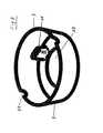
- FIG. 3shows a possible embodiment of a funnel-like device 9, comprising a collar-like funnel-like wall 8 and a Ablenkblende 11, against which the hot liquid milk can be injected through the nozzle 7. Due to the relatively high speed of the rotating milk is correspondingly through the opening 13th Air sucked from below, creating a certain turbulence of the milk and thus as a product milk foam. This is finally also issued through the opening 13 down. So that the device is optionally held in the correct position in the receptacle 21 together with the container, it is possible to provide, for example, so-called positioning aids 24.
- FIG. 4shows a horizontal section through a milk frothing unit analogous to that shown in FIG. 3 ,
- the milkis injected in a sharp stream in the direction of arrow 10 with a tangential component in the annular chamber 12 of the device 8.
- the resultis a rotating milk layer, wherein the milk undergoes a first foaming due to the violent turbulence of the incoming jet.
- the rotation in the direction of arrow 12 'around the center of rotation 16 of the device 9having, for example, a funnel-like wall 8.
- This type of foamingcreates an initially quite large-pored and unstable foam is smashed in further passes through the milk jet and so creates the desired fine-pored stable foam 14. The necessary air is sucked through the outlet opening 13.
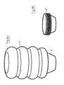
- FIGS. 5a and 5bshow a further possible embodiment of a container according to the invention, for example in the form of a bellows. It shows FIG. 5a the container 1 ', placed on the funnel-shaped device 9 in the starting position, containing the liquid, such as milk. In FIG. 5b If the bellows-type container is compressed and designated by the reference numeral 1 ", this bellows-like configuration of the container makes it easily compressible by applying pressure or by means of a piston-like instrument.
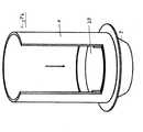
- FIG. 6again shows in perspective a further embodiment of an inventive cup-like container 1, mounted on a funnel-shaped device 9.
- the funnel-like device 9an upper retaining ring 28, which is provided around the cup 1 in a corresponding receptacle 21, for example in a coffee machine, in the correct position.
- compressed air DBy applying compressed air D, in turn, the milk from the cup 1 can be driven into the funnel-shaped device 9, where the foam is generated.
- the milk foampasses through the opening 13, for example, to be dispensed into a coffee cup.
- FIGS. 7a and 7banother embodiment variant of a cup 1 according to the invention is shown, having an upper wall 29 designed as a piston, for example, which can be pressed along the wall by applying a corresponding tool.
- the cup 1is cartridge-shaped, and, as in the preceding examples, may be directly integrally connected to the funnel-shaped device 9 to form a one-piece capsule 20 in which the turbulence of the expelled milk can take place.
- a piston-like upper wallcan also a fixedly arranged membrane-like wall may be provided, which can be punctured by means of a nozzle or pin-like device, for example, in a region 30 (shown in dashed lines) in order to build up the pressure in the inner 2 of the upper container region.
- FIG. 8schematically shows in section a different embodiment of the inventive arrangement in that here the cup is not placed on a funnel-shaped assembly 9, but connected to a Venturubehrartig formed foam-forming body 9 and placed on this.
- a channel-shaped passage 10is provided with a tapered cross section, in which a lateral air pipe 35 opens, for introducing air, steam or compressed air.
- a lateral air pipe 35opens, for introducing air, steam or compressed air.
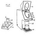
- FIG. 9finally shows a device 41 for producing a milk foam, such as a cappuccino, a coffee latte macchiato, etc ..
- a milk-containing capsule 20is entered, after which a lid 23 is folded down onto the upper opening of the capsule 20.
- the milk in the capsule 20is first of all heated by means of a switch 45 and subsequently, for example, by means of a displaceable piston or by generating pressure or by introducing compressed air into the capsule, the milk is expelled from the container region into the flow region.
- the expulsionis analogous to the descriptions as stated with reference to the FIGS.
- the device responsible for the production of the milk foam device or the funnel-like cupis integrally connected to the container area for forming the capsule.
- the now generated foamis injected into the container 15 as a cup or a cup containing a coffee to produce the corresponding desired coffee.
- a corresponding capsule 20can be selected from a stand 4, which capsule 20 is initially closed by a corresponding cover 2.
- the closure 2may either be removed prior to entering the device 41, or may not be removed for the production of the milk foam.
- the container or the capsule 20(container 1 + funnel-shaped device 9 integrally connected to each other) is a disposable container, which has to be as inexpensive as possible.
- the container or the capsuleshould, if possible, be producible in a cost-effective production method, for example by means of deep drawing.
- the container or the capsulecan either be made of a polymer material, or of aluminum or other suitable material which can be recycled after use.
- FIGS. 1 to 9 illustrated embodimentsare, of course, only embodiments to explain the present invention. In no way the invention is limited to the embodiments and of course any other type of containers for the presentation of the milk can be selected, as well as other embodiments for the production of the milk foam.
- the present inventionis by no means limited to the production of a milk foam, but the proposed method according to the invention as well as devices can generally be used for producing a foam from a liquid food.
Landscapes
- Chemical & Material Sciences (AREA)
- Chemical Kinetics & Catalysis (AREA)
- Engineering & Computer Science (AREA)
- Dispersion Chemistry (AREA)
- Mechanical Engineering (AREA)
- Food Science & Technology (AREA)
- Apparatus For Making Beverages (AREA)
- Tea And Coffee (AREA)
- Jellies, Jams, And Syrups (AREA)
- Dairy Products (AREA)
- Containers And Packaging Bodies Having A Special Means To Remove Contents (AREA)
- Food-Manufacturing Devices (AREA)
Abstract
Description
Translated fromGermanDie vorliegende Erfindung betrifft ein Verfahren zur Herstellung eines wenigstens teilweise aufgeschäumten Lebensmittels, wie insbesondere von mindestens teilweise geschäumter Milch, eine Anordnung zum Erzeugen eines wenigstens teilweise aufgeschäumten Lebensmittels, ein kapselartiges Behältnis zum Erzeugen eines aufgeschäumten Lebensmittels, und schliesslich eine Kaffeemaschine mit einer Anordnung.The present invention relates to a process for producing an at least partially frothed foodstuff, such as, in particular, at least partially frothed milk, an arrangement for producing an at least partially frothed food, a capsule-like container for producing a frothed foodstuff, and finally a coffee machine with an arrangement.
Die Kaffeeherstellung erfolgt je länger je mehr mittels so genannter Kapselsysteme. Dabei wird Kaffeepulver in Kapseln oder Beuteln verpackt in eine Kaffeemaschine eingelegt, die Kapsel mindestens teilweise zerstört und das Pulver mittels Heisswasser gelöst zur Ausgabe des Kaffees in gewünschter Form bzw. Zubereitungsart.The coffee production takes place the longer the more by means of so-called capsule systems. Coffee powder is packed in capsules or bags in a coffee machine, the capsule is at least partially destroyed and dissolved the powder by means of hot water for dispensing the coffee in the desired form or preparation.
Falls Milch beispielsweise für einen Capuccino oder Milchkaffee benötigt wird, wird diese beispielsweise mittels Heissdampf erhitzt und aufgeschäumt bzw. gegebenenfalls weiter zum Aufschäumen mechanisch bearbeitet. Entsprechend wird in einer Vielzahl von Druckschriften die Zubereitung von Milchschaum mittels Heissdampf beschrieben. Beispielsweise wird in der
Ein Vorschlag, wie Getränke aufgeschäumt werden Können, ohne die Verwendung von Heissdampf, is in der
Schliesslich schlägt die
Entgegen der Kaffeezubereitung ist die Erzeugung eines Milchschaumes aufwendig und falls dieser mittels Heissdampf erzeugt wird, wird die Milch durch den Heissdampf teilweise verwässert und zudem werden die für das Erzeugen des Schaums benötigten Utensilien und Behältnisse verschmutzt.Contrary to the preparation of coffee, the production of a milk foam is complicated and if this is produced by means of hot steam, the milk is partially diluted by the hot steam and also the utensils and containers required for the production of the foam are polluted.
Es ist eine Aufgabe der vorliegenden Erfindung eine Vereinfachung der Milchbearbeitung vorzuschlagen, um diese in wenigstens teilweiser Schaumform für die Herstellung, beispielsweise eines Capuccinos, eines Milchkaffees, etc., entsprechend zu behandeln, wobei eine Verschmutzung von Apparateteilen wie insbesondere einer Kaffeemaschine weitgehendst verhindert wird.It is an object of the present invention to propose a simplification of the milk processing in order to treat them in at least partial foam mold for the production, for example, of a cappuccino, a milk coffee, etc., with a pollution of apparatus parts such as in particular a coffee machine is largely prevented.
Verallgemeinert ist es eine Aufgabe der vorliegenden Erfindung ein Verfahren und eine Vorrichtung vorzuschlagen, um flüssige Lebensmittel auf einfache Art und Weise in wenigstens teilweise schaumartige Form zu bringen.Generally, it is an object of the present invention to propose a method and a device for bringing liquid foods into at least partially foamy form in a simple manner.
Die Erfindung wird mittels einem kapselartigen Gebilde nach Anspruch 1 sowie Verfahrens gemäss dem Wortlaut nach Anspruch 7 gelöst.The invention is achieved by means of a capsule-like structure according to claim 1 and method according to the wording of
Vorgeschlagen wird, dass das flüssige Lebensmittel, welches wenigstens teilweise aufzuschäumen ist, in einem Behältnis, wie beispielsweise einer Kapsel oder einem Beutel vorgelegt wird, das flüssige Lebensmittel gegebenenfalls noch im Behältnis ohne Zufuhr von Heissdampf in das Behältnis erwärmt und anschliessend durch Erzeugung eines Druckes aus dem Behältnis ausgetrieben wird. Das aus dem Behältnis ausgetriebene Lebensmittel wird in eine Vorrichtung eingegeben, in welcher wenigstens teilweise eine turbulente Strömung erzeugt wird, um das flüssige Lebensmittel aufzuschäumen. Schliesslich wird das Lebensmittel aus dem Behältnis oder der Vorrichtung in gewünschter Form für die weitere Verwendung ausgegeben, wie beispielsweise um einen Capuccino herzustellen.It is proposed that the liquid food, which is at least partially froth, is placed in a container, such as a capsule or a bag, the liquid food possibly still heated in the container without supply of hot steam into the container and then by generating a pressure is expelled from the container. The food expelled from the container is introduced into a device in which at least partially a turbulent flow is created to foam the liquid food. Finally, the food is dispensed from the container or device in the desired form for further use, such as to produce a cappuccino.
Das Austreiben der Flüssigkeit aus dem Behältnis kann einerseits durch Druckluft erfolgen, indem durch eine Öffnung im Behältnis Druckluft ins Innere gepresst wird, oder aber indem das Behältnis zusammengedrückt wird oder eine Wandung gegen das Innere hin verschoben wird. Dabei kann entweder eine düsenartige Öffnung in Folge der Druckluft automatisch geöffnet werden, das Öffnen kann durch Entfernen eines Schiebers, einer Membran, etc. Schrumpfen entweder der Oeffnung entlang einer Sollbruchstelle oder einer Membran.The expulsion of the liquid from the container can be done on the one hand by compressed air by compressed air is forced into the interior through an opening in the container, or by the container is compressed or a wall is moved towards the inside. In this case, either a nozzle-like opening due to the compressed air can be opened automatically, the opening can be made by removing a slide, a membrane, etc. Shrinking either the opening along a predetermined breaking point or a membrane.
Die ausgetriebene Flüssigkeit, welche beispielsweise im Falle einer Milch für die Erzeugung eines Capuccinos vorab beispielsweise mittels Mikrowelle, Infrarot, durch Zuführen von Heissdampf an das Behältnis, etc. erwärmt worden ist, wird in eine geeignete Vorrichtung eingegeben, wie beispielsweise eingespritzt, wie ein Trichter, ein Wirbelkörper, eine schlauchartige Vorrichtung, etc. um in dieser eine turbulente Strömung zu erzeugen zwecks Aufschäumen. Dabei ist wichtig, dass eine Verwirbelung mit der in der Vorrichtung vorhandenen Luft ermöglicht wird, zur wenigstens teilweisen Erzeugung eines Schaumes. Hierzu ist es auch möglich zusätzlich Luft von aussen in die Vorrichtung einzugeben, oder diese kann auch infolge der Strömung in der Vorrichtung selbsttätig angesogen werden.The expelled liquid, which has been heated in the case of a milk for producing a cappuccino in advance, for example, by means of microwave, infrared, by supplying hot steam to the container, etc., is input to a suitable device, such as injected, such as a funnel , a vertebral body, a tube-like device, etc., to generate turbulent flow therein for foaming. It is important that a turbulence with the existing air in the device is made possible for at least partial generation of a foam. For this purpose, it is also possible to additionally input air from the outside into the device, or it can also be sucked in automatically due to the flow in the device.
Schliesslich wird die schaumartige Flüssigkeit, wie beispielsweise der Milchschaum, durch eine Ausgabeöffnung, wie beispielsweise eine Düse, ausgegeben, um beispielsweise in einer Kaffeetasse einen Capuccino zu erzeugen.Finally, the foamy liquid, such as the milk froth, is dispensed through a dispensing opening, such as a nozzle, to produce a cappuccino in a coffee cup, for example.
Weitere bevorzugte Ausführungsvarianten des erfindungsgemässen Verfahrens sind in abhängigen Ansprüchen charakterisiert.Further preferred embodiments of the inventive method are characterized in dependent claims.
Entsprechend vorgeschlagen wird eine Anordnung zum Erzeugen eines wenigstens teilweise aufgeschäumten Lebensmittels, wie insbesondere von aufgeschäumter Milch. Die Anordnung weist mindestens ein Behältnis auf, welches vorgesehen ist für das Vorlegen der aufzuschäumenden Flüssigkeit. Das Behältnis kann derart sein, dass entweder durch von aussen zugeführte Druckluft die Flüssigkeit ausgetrieben werden kann, oder aber die Wandungen sind derart, dass sie zusammengedrückt bzw. einwärts verschiebbar sind.Accordingly, an arrangement is proposed for producing an at least partially frothed food, such as, in particular, frothed milk. The arrangement has at least one container which is provided for the presentation of the liquid to be foamed. The container may be such that either through from outside supplied compressed air, the liquid can be expelled, or the walls are such that they are compressed or inwardly displaceable.
Weiter weist die Anordnung eine vorzugsweise mit dem Behältnis verbundene Vorrichtung auf, in welche die Flüssigkeit aus dem Behältnis einspritzbar bzw. eingebbar ist, und in welcher eine turbulente Strömung der Flüssigkeit erzeugbar ist bzw. die Flüssigkeit mit Luft wirbelartig durchmischt werden kann. Die Vorrichtung kann trichterartig sein, kann irgendwelche Strömungsblenden, Richtungsumkehrblenden, Verengungen im Durchfluss der Flüssigkeit, eine Luftzufuhr von aussen, etc. aufweisen, wesentlich ist, dass durch entsprechende Massnahmen die Flüssigkeit aufgeschäumt wird.Furthermore, the arrangement has a preferably connected to the container device into which the liquid from the container can be injected or entered, and in which a turbulent flow of the liquid can be generated or the liquid can be vortex mixed with air. The device may be funnel-like, may have any flow orifice, direction reversal orifices, restrictions in the flow of the liquid, an air supply from the outside, etc., it is essential that the liquid is foamed by appropriate measures.
Gemäss einer Ausführungsvariante ist es möglich, das Behältnis integral mit der Vorrichtung zur Bildung einer einteiligen Kapsel zu verbinden.According to one embodiment, it is possible to connect the container integrally with the device for forming a one-piece capsule.
Die Anordnung kann weiter ein Heizaggregat wie beispielsweise ein Mikrowelle, ein Infrarotaggregat, ein Heissdampferzeuger, etc. aufweisen um die Flüssigkeit im Behältnis vor dem Austreiben in die Vorrichtung zu erhitzen. Im Falle der Verwendung von Heissdampf ist es vorteilhaft, wenn dieser nicht mit dem flüssigen Lebensmittel in Kontakt gerät.The assembly may further comprise a heating unit such as a microwave, an infrared aggregate, a hot steam generator, etc. to heat the liquid in the container prior to expulsion into the apparatus. In the case of the use of hot steam, it is advantageous if it does not come into contact with the liquid food.
Schliesslich weist das Behältnis oder die Vorrichtung eine Ausgabeöffnung bzw. eine Ausgabedüse auf, durch welche das aufgeschäumte Lebensmittel, wie beispielsweise die aufgeschäumte Milch, austreibbar ist.Finally, the container or the device has an outlet opening or an outlet nozzle, through which the foamed food, such as, for example, the frothed milk, can be expelled.
Bevorzugte Ausführungsvarianten der erfindungsgemässen Anordnung sind ebenfalls in abhängigen Ansprüchen charakterisiert.Preferred embodiments of the inventive arrangement are also characterized in dependent claims.
Schliesslich vorgeschlagen wird eine Kaffeemaschine aufweisend eine Aufnahme, in welche die erfindungsgemässe Anordnung bzw. die oben erwähnte Kapsel eingegeben werden kann, und welche entsprechende Einrichtungen aufweist, um beispielsweise die Milch zu erhitzen, um Dampf oder Druckluft zu erzeugen, oder um mechanisch das Behältnis zusammenzudrücken, etc.Finally, a coffee machine is proposed comprising a receptacle into which the inventive arrangement or the above-mentioned capsule can be entered, and which has corresponding means to heat, for example, the milk to produce steam or compressed air, or to mechanically compress the container , Etc.
Der Vorteil einer derart erfindungsgemäss vorgeschlagenen Kaffeemaschine liegt darin, dass die Anordnung bzw. die Kapsel zum Erzeugen des Milchschaumes quasi autonom in die Kaffeemaschine eingegeben werden kann und nach Erzeugen des Milchschaumes wieder daraus entfernt werden kann, wie beispielsweise die heute bekannten und eingangs erwähnten Kaffeepulverkapseln bzw. -beutel. Dabei werden keine Teile der Kaffeemaschine in irgendeiner Art und Weise verschmutzt, lediglich die erfindungsgemässe Anordnung kann als Einweggebrauchsartikel entsorgt werden, wie beispielsweise kompostiert werden, falls die einzelnen Komponenten aus biologisch abbaubaren Materialien gefertigt sind.The advantage of a coffee machine proposed in this way according to the invention is that the arrangement or the capsule for producing the milk foam can be quasi autonomously entered into the coffee machine and removed again after the milk foam has been produced, for example the coffee powder capsules or coffee capsules known today bag. In this case, no parts of the coffee machine are contaminated in any way, only the inventive arrangement can be disposed of as disposable, such as composted, if the individual components are made of biodegradable materials.
Die Erfindung wird nun beispielsweise und unter Bezug auf die beigefügten Figuren näher erläutert.The invention will now be explained in more detail by way of example and with reference to the accompanying drawings.
Dabei zeigen:
- Fig. 1
- schematisch im Querschnitt eine erfindungsgemässe Anordnung zum Erzeugen eines Milchschaumes,
- Fig. 2
- schematisch anhand von Einzelteilen einer Anordnung einen Verschluss zum Verschliessen des Behältnisses,
- Fig. 3
- schematisch in Perspektive eine Vorrichtung zum Erzeugen einer turbulenten Strömung zur Erzeugung des Schaumes,
- Fig. 4
- einen horizontalen Schnitt durch die Milchaufschäumvorrichtung gemäss
Fig. 3 - Fig. 5a,b
- eine mögliche Ausführungsvariante eines Behältnisses für das Vorlegen der Flüssigkeit,
- Fig. 6
- in Perspektive eine weitere Ausführungsvariante eines erfindungsgemässen Behältnisses,
- Fig. 7a,b
- wiederum eine weitere Ausführungsvariante eines erfindungsgemässen Behältnisses bzw. einer Kapsel
- Fig. 8
- schematisch eine weitere Ausführungsvariante einer erfindungsgemässen Anordnung zum Erzeugen eines Schaumes, wie eines Milchschaumes, und
- Fig. 9
- ein konkretes Ausführungsbeispiel eines Gerätes zum Erzeugen von Milchschaum.
- Fig. 1
- schematically in cross-section an inventive arrangement for producing a milk foam,
- Fig. 2
- schematically a view of individual parts of an arrangement a closure for closing the container,
- Fig. 3
- schematically in perspective a device for generating a turbulent flow to produce the foam,
- Fig. 4
- a horizontal section through the Milchaufschäumvorrichtung according
Fig. 3 - Fig. 5a, b
- a possible embodiment of a container for the presentation of the liquid,
- Fig. 6
- in perspective, a further embodiment of a container according to the invention,
- Fig. 7a, b
- in turn, a further embodiment of a container according to the invention or a capsule
- Fig. 8
- schematically a further embodiment of an inventive arrangement for producing a foam, such as a milk foam, and
- Fig. 9
- a concrete embodiment of an apparatus for producing milk foam.
Unterhalb der Öffnung 13 kann eine Konsole 17 vorgesehen sein, welche zu einer Kaffeemaschine gehört, welche die Aufnahme 21 für das Behältnis 1 aufweist. Auf der Konsole 17 kann beispielsweise eine Kaffeetasse 15 angeordnet werden, in welcher bereits der heisse Kaffee vorhanden ist.Below the
Schliesslich oberhalb des Behältnisses 1 kann eine kolbenartige Vorrichtung 25 vorgesehen sein, aufweisend eine Druckleitung 26 welche für das Eindrücken der Decke des Behältnisses 1 mittels beispielsweise Druck vorgesehen ist.Finally, above the container 1, a piston-
Nachfolgend nun die Funktionsweise der erfindungsgemässen Anordnung, wie dargestellt in
Nach Eingeben des Behältnisses 1 zusammen mit der Vorrichtung 9 in die Aufnahme 21, beispielsweise einer Kaffeemaschine, wird die Erzeugung des Milchschaumes, beispielsweise mittels eines Schalters oder Druckknopfes ausgelöst. Nun wird zunächst die Milch 3 im Behältnis 1 erhitzt, was beispielsweise mittels Mikrowelle, Infrarot oder einem anderen geeigneten Heizaggregat erfolgen kann. Das Erhitzen kann auch mittels Dampf erfolgen, welcher das Behältnis umströmt.After entering the container 1 together with the
Nach Erwärmen der Milch wird der Kolben 25 betätigt, welcher die obere Wandung des Behältnisses 1 eindrückt und so einen gewissen Druck im Behältnis 1 erzeugt. Nun wird beispielsweise eine feine Membran an der Ausgabedüse 7 weggepresst, oder aber das Öffnen kann auf irgendeine andere geeignete Art und Weise automatisch erfolgen. Der heisse Milchstrahl wird in die trichterförmige Vorrichtung 9 eingespritzt, in welcher eine gewisse Verwirbelung der Milch erzeugt wird, beispielsweise infolge der Umlenkblenden 11. Der spiralförmige, schaumerzeugende Flüssigkeitsstrom in der trichterförmigen Vorrichtung 9 gelangt schliesslich zur Öffnung 13, durch welche die aufgeschäumte Milch in die darunter angeordnete Tasse 15 ausgegeben wird. Der Druckaufbau kann aber auch anstelle eines Kolbens bspw. mittels einer die obere Abdeckung des Behältnisses 1 durchstossende Druckdüse erfolgen.After heating the milk, the
Nach erfolgtem Ausgeben des Milchschaumes kann beispielsweise das Behältnis 1 mit der Vorrichtung 9 automatisch in ein entsprechend dafür vorgesehene Kammer ausgeworfen werden, oder aber kann manuell entfernt werden. Es versteht sich von selbst, dass keine Teile der Kaffeemaschine, aufweisend die Aufnahme 21, in irgendeiner Art und Weise mit Milch in Berührung gekommen sind. Somit entsteht keine Verschmutzung und die Kaffeemaschine muss nach erfolgtem Gebrauch nicht gereinigt werden.After the milk foam has been dispensed, for example, the container 1 with the
Da zum Erwärmen der Milch und dem anschliessenden Erzeugen des Milchschaums kein Heissdampf verwendet wird, erfolgt auch keine Verwässerung der Milch im erzeugten Schaum.Since no hot steam is used for heating the milk and the subsequent production of the milk foam, no dilution of the milk in the foam produced.
In den
Je nach herzustellendem Kaffee, ob Cappuccino, ein Milchkaffe, ein Kaffee Latte Macchiato, etc. kann eine entsprechende Kapsel 20 aus einem Ständer 4 ausgewählt werden, welche Kapsel 20 zunächst noch durch einen entsprechenden Deckel 2 verschlossen ist. Der Verschluss 2 kann entweder vor dem Eingeben in das Gerät 41 entfernt werden, oder aber muss für die Erzeugung des Milchschaums nicht entfernt werden.Depending on the coffee to be produced, whether cappuccino, a milk coffee, a coffee latte macchiato, etc., a corresponding
Vorzugsweise handelt es sich bei dem Behältnis bzw. der Kapsel 20 (Behältnis 1 + trichterförmige Vorrichtung 9 integral miteinander verbunden) um ein Wegwerfgebinde, welches möglichst kostengünstig zu sein hat. Das heisst, dass das Behältnis bzw. die Kapsel möglichst in einem kostengünstigen Herstellverfahren wie beispielsweise mittels Tiefzugverfahren herstellbar sein sollte. Das Behältnis bzw. die Kapsel kann entweder aus einem Polymermaterial gefertigt sein, oder aber aus Aluminium oder einem andere geeigneten Material, welches nach Gebrauch rezyklisiert werden kann.Preferably, the container or the capsule 20 (container 1 + funnel-shaped
Aus den in den
Wie eingangs erwähnt ist auch die vorliegende Erfindung keinesfalls auf die Herstellung eines Milchschaumes limitiert, sondern die erfindungsgemäss vorgeschlagenen Verfahren wie auch Vorrichtungen können generell für das Herstellen eines Schaumes aus einem flüssigen Lebensmittel verwendet werden.As mentioned above, the present invention is by no means limited to the production of a milk foam, but the proposed method according to the invention as well as devices can generally be used for producing a foam from a liquid food.
Der grosse Vorteil der erfindungsgemässen Anordnung bzw. der Verfahren liegt, wie bereits oben erwähnt darin, dass auf einfachste Art und Weise ein Schaum erzeugt werden kann, ohne dass die Umgebung in irgendeiner Art und Weise verschmutzt wird. Der Aufwand zur Schaumerzeugung wie auch das Reinigen und das Entsorgen der diversen Behältnisse bzw. Kapsel ist äusserst einfach.The great advantage of the inventive arrangement or the method is, as already mentioned above, that in the simplest way, a foam can be produced without the environment is polluted in any way. The effort for foam generation as well as the cleaning and disposal of the various containers or capsule is extremely simple.
Claims (19)
- Capsule-type structure (20) for producing without superheated steam an at least partially frothed liquid food such as in particular milk, with:- at least one section (1) provided for the storage of a liquid food (3),- at least one further section (9) for frothing the liquid food, whereby the two sections are separable from one another in such a way that the separation may be at least partially interrupted mechanically or upon pressure from the one section, in order to expel the liquid food into the further section for frothing, and- at least a discharge element (13) at the further section for discharging the frothed food,
characterised in that- the separation is formed such that the liquid food is supplied into the further section in such a manner that it froths. - Capsule-type structure according to claim 1,characterised in that means are provided in the further section for setting liquid food introduced into the further section into a turbulent flow in such a way that it froths.
- Structure according to claim 2,characterised in that the means is funnel-like and/or cup-shaped, and has flow screens (11, 37), impact cams, etc. along an inner surface for generating the turbulent flow or for frothing the liquid.
- Structure according to one of the claims 1 to 3,characterised in that the one section is easily deformable or compressible and has a discharge opening (7), which is opened automatically by generating a pressure in the container.
- Capsule-type structure according to one of the claims 1 to 3,characterised in that in the one section at least one wall is displaceable by external pressure or pierceable by means of a nozzle in such a way that an increased pressure can be generated in the one section.
- Capsule-type structure according to one of the claims 1 to 5,characterised in that it is a single-use package or a disposable article, which for instance can be produced by means of a deep drawing process.
- Method for producing an at least partially frothed food by using a capsule-type structure according to one of the claims 1 to 6, such as in particular at least partially frothed milk or a milk product,characterised in that the liquid food held in the one section is expelled out of the one section and at least partially frothed without supplying superheated steam such as in particular hot water steam, and at least partially frothed and subsequently discharged by generating an at least partially turbulent flow.
- Method according to claim 7,characterised by heating the section with the liquid food, or the liquid food contained therein, without supplying steam into the container, and subsequently expelling the heated, possibly frothed liquid food, at least partially frothing, and subsequently discharging the at least partially frothed liquid food.
- Method according to one of the claims 7 or 8,characterised by heating the liquid food, such as in particular milk, using microwaves, infrared or the like energy in the one section.
- Method according to one of the claims 7 to 9,characterised by expelling the liquid food out of the one section by means of compressed air, by impression, or by displacing a wall towards the interior of the one section to generate excess pressure, and subsequently possibly performing the frothing in a further section connected to the one section.
- Method according to one of the claims 7 to 10,characterised by introducing the liquid food into a further funnel-like or cup-like section, in such a way that an at least nearly spiral-shaped or circular flow arises, whereby the turbulence occurs due to asymmetrical injection of the liquid food into the further section and/or arranging of a configuration of screens, swirling bodies or the like in the further section.
- Method according to one of the claims 7 to 11,characterised by spraying the liquid food such as in particular milk into the cup-like further section in a sharp jet having a tangential component, whereby a rotating liquid layer such as a milk layer arises, whereby the liquid experiences a first frothing due to the strong turbulence of the incident jet, a coarse-pored and unstable froth being initially formed by this kind of frothing, which is battered upon further passages by the liquid jet, whereby the desired fine-pored stable froth results.
- Method according to one of the claims 7 to 12,characterised by injecting the liquid food into a further section, having different cross-sections in a flow direction of the food for generating a turbulent flow, and possibly supplying air from outside in areas having tapered cross-section to swirl the food.
- Method according to one of the claims 10 to 13,characterised by the frothing occurring in the further section using so-called swirl or twist bodies, which are possibly arranged so as to be freely movable or freely rotatable.
- Arrangement for performing the method according to one of the claims 7 to 14, for producing an at least partially frothed liquid food, such as in particular milk, comprising:- a container (1) provided for the storage of a liquid food (3),- a device (25) for expelling the liquid out of the container,- a flow device (9) in which the expelled liquid is set into an at least partially turbulent flow, and- a discharge element (13) for discharging the at least partially frothed food.
- Arrangement according to claim 15,characterised in that the flow device is funnel-like and/or cup-shaped, and has flow screens (11, 37), impact cams, etc. along an inner surface for generating the turbulent flow or for frothing the liquid.
- Arrangement according to one of the claims 15 or 16,characterised in that the container (1), the flow device (9), and the discharge element (13) are integrally connected to form a capsule-type structure which is removably placeable in the arrangement.
- Coffee machine with an arrangement according to one of the claims 15 to 17.
- Coffee machine according to claim 18 for making and/or dispensing in particular portioned coffee, in varying forms of consumption, comprising a receptacle for coffee powder or powder in portioned form, a heating device for making hot water, as well as a mixing device for mixing the coffee powder with hot water, and a discharge element for discharging the brewed coffee powder, furthercharacterised in:- a receptacle (21) for arranging the capsule-type structure (20) according to one of the claims 1 to 7, containing liquid milk (3),- a heating element for heating the milk,- a device for expelling the milk out of the one section for generating an at least partially turbulent flow of the milk in order to froth the milk or to expel the froth out of the capsule-type structure, and- possibly a discharge opening (13) for discharging the frothed milk.
Applications Claiming Priority (3)
| Application Number | Priority Date | Filing Date | Title |
|---|---|---|---|
| CH18132006 | 2006-11-10 | ||
| CH8072007 | 2007-05-18 | ||
| PCT/EP2007/061802WO2008055845A2 (en) | 2006-11-10 | 2007-11-01 | Frothing liquid food |
Publications (2)
| Publication Number | Publication Date |
|---|---|
| EP2086667A2 EP2086667A2 (en) | 2009-08-12 |
| EP2086667B1true EP2086667B1 (en) | 2012-06-27 |
Family
ID=39364875
Family Applications (1)
| Application Number | Title | Priority Date | Filing Date |
|---|---|---|---|
| EP07822146ANot-in-forceEP2086667B1 (en) | 2006-11-10 | 2007-11-01 | Frothing liquid food |
Country Status (4)
| Country | Link |
|---|---|
| US (1) | US8367133B2 (en) |
| EP (1) | EP2086667B1 (en) |
| JP (1) | JP2010508927A (en) |
| WO (1) | WO2008055845A2 (en) |
Families Citing this family (23)
| Publication number | Priority date | Publication date | Assignee | Title |
|---|---|---|---|---|
| GB2449631B (en) | 2007-05-21 | 2012-02-15 | Doo Technologies Fze | Method and system for processing of images |
| EP2255886B1 (en) | 2009-05-29 | 2012-04-18 | Mercedes Sánchez Cubero | Device for foaming and dispensing liquids |
| DE102010023781B4 (en)* | 2010-06-15 | 2015-09-17 | Volker Barth | Device for foaming a liquid |
| IT1401028B1 (en)* | 2010-07-30 | 2013-07-12 | Bianchelli | INNOVATIVE SINGLE-USE CARTRIDGE FOR THE PREPARATION OF VARIOUS TYPES OF HOT DRINKS |
| IT1401403B1 (en)* | 2010-08-13 | 2013-07-26 | Bianchelli | INNOVATIVE DISPOSABLE CARTRIDGE FOR THE PREPARATION OF HOT DRINKS |
| IT1403543B1 (en)* | 2011-01-31 | 2013-10-31 | Sarong Spa | CAPPULE FOR BEVERAGES |
| IT1403541B1 (en)* | 2011-01-31 | 2013-10-31 | Sarong Spa | DRINKING MACHINE FOR BEVERAGES |
| IT1403542B1 (en)* | 2011-01-31 | 2013-10-31 | Sarong Spa | CAPPULE FOR BEVERAGES |
| DE102011077776B4 (en) | 2011-06-17 | 2013-11-14 | Wmf Württembergische Metallwarenfabrik Ag | Device for heating and frothing a beverage product |
| ITRE20110048A1 (en)* | 2011-06-22 | 2012-12-23 | Ind Societa Cooperati Va Coop | DISPOSABLE CARTRIDGE FOR DRINK PREPARATION |
| ITMO20120006A1 (en)* | 2012-01-12 | 2013-07-13 | Sarong Spa | CAPPULE FOR BEVERAGES |
| US10150610B2 (en) | 2012-01-12 | 2018-12-11 | Sarong Societa' Per Azioni | Capsule for beverage |
| ITMO20120025A1 (en)* | 2012-02-03 | 2013-08-04 | Sarong Spa | CAPPULE FOR BEVERAGES |
| ITMO20120043A1 (en) | 2012-02-22 | 2013-08-23 | Sarong Spa | CAPPULE FOR BEVERAGES |
| ITAN20130047A1 (en)* | 2013-03-06 | 2014-09-07 | Sauro Bianchelli | APPLIANCE |
| BR112015021789A2 (en) | 2013-03-11 | 2020-06-16 | Koninklijke Philips Nv | device for foaming in a liquid and coffee maker |
| CA2905217C (en) | 2013-04-03 | 2016-11-08 | 2266170 Ontario Inc. | Capsule machine and components |
| AT514716B1 (en)* | 2013-09-02 | 2015-09-15 | Pro Aqua Diamantelektroden Produktion Gmbh & Co Kg | Disposable capsule and method of making a serving of beverage in a beverage vending machine |
| MX2017000160A (en)* | 2014-06-25 | 2017-04-25 | Nestec Sa | Disposable foaming device. |
| PT109303B (en)* | 2016-04-07 | 2021-02-15 | Novadelta Comercio Ind Cafes Sa | EXTRACTION DEVICE WITH MOBILE CAPSULE SUPPORT |
| IT201700037089A1 (en)* | 2017-04-04 | 2018-10-04 | Illycaffe Spa | ASSEMBLY OF A COLD DRINK |
| US11649153B2 (en) | 2020-06-25 | 2023-05-16 | TechFit Inc. | Beverage infusion apparatus and method for infusing gas into a beverage |
| US11649152B2 (en) | 2020-06-25 | 2023-05-16 | TechFit Inc. | Beverage infusion apparatus and method for infusing gas into a beverage |
Family Cites Families (20)
| Publication number | Priority date | Publication date | Assignee | Title |
|---|---|---|---|---|
| GB717784A (en)* | 1951-04-13 | 1954-11-03 | Stamicarbon | Process and apparatus for homogenizing emulsions |
| IT1198946B (en)* | 1984-10-26 | 1988-12-21 | Fulmine Srl | DEVICE FOR HEATING AND EMULSION OF MILK IN SPECIES FOR THE PREPARATION OF THE SO-CALLED CAPPUCCINO |
| IT218832Z2 (en) | 1989-11-10 | 1992-11-05 | Girolamo Silvestro Di | LIQUID EMULSIFIER DEVICE, IN PARTICULAR MILK |
| DE4220986A1 (en) | 1992-06-26 | 1994-01-05 | Gotthard Dipl Ing Mahlich | Device for preparing milk foam for cappuccino |
| US5473972A (en)* | 1994-10-24 | 1995-12-12 | Conair Corporation | Milk container attachment for cappucino maker |
| US5611262A (en)* | 1996-06-24 | 1997-03-18 | Conair Corporation | Cappuccino maker |
| ES2221111T3 (en) | 1997-11-27 | 2004-12-16 | C.M.I. S.R.L. | HINGE DEVICE, IN PARTICULAR FOR THE DOOR OF APPLIANCES AND SIMILARS, CONTRARRESTING AND SELF-REGULATING MEANS. |
| ES2260218T3 (en) | 2000-05-19 | 2006-11-01 | Rancilio Macchine Per Caffe' S.P.A. | DEVICE FOR HEATING AND MAKING FOAM A LIQUID, IN PARTICULAR MILK. |
| US6289796B1 (en)* | 2001-02-23 | 2001-09-18 | Simatelex Manufactory Company Limited | Hot milk dispenser |
| DE60236385D1 (en)* | 2001-04-27 | 2010-06-24 | Mars Inc | Beverage manufacturing device and process |
| NL1020834C2 (en) | 2002-06-12 | 2003-12-15 | Sara Lee De Nv | Device and method for preparing a beverage suitable for consumption with a fine-bubble froth layer. |
| EP1430819A1 (en)* | 2002-12-16 | 2004-06-23 | Nestec S.A. | Connector piece for the steam outlet of a coffee machine |
| US7607385B2 (en)* | 2003-01-24 | 2009-10-27 | Kraft Foods R & D, Inc. | Machine for the preparation of beverages |
| ATE353583T1 (en) | 2003-03-24 | 2007-03-15 | Nestec Sa | DISPOSABLE PACKAGING FOR DISTRIBUTING A PUMPABLE LIQUID FROM A VENTURI DEVICE |
| ATE395855T1 (en) | 2003-11-20 | 2008-06-15 | Steiner Ag Weggis | DEVICE FOR PRODUCING MILK OR MILK FOAM DRINKS |
| EP1699328B2 (en)* | 2003-12-22 | 2014-07-02 | Koninklijke Philips N.V. | Liquid cartridge for use in a beverage system |
| ITMI20040213A1 (en) | 2004-02-10 | 2004-05-10 | Tecnola S N C Di Sanna Massimo | DEVICE TO EMULSATE MILK AND AIR |
| NL1029155C2 (en) | 2004-10-19 | 2006-04-20 | Sara Lee De Nv | System and method for preparing a drink suitable for consumption. |
| ATE415120T1 (en) | 2005-02-08 | 2008-12-15 | Saeco Ipr Ltd | ARRANGEMENT FOR PRODUCING MILK FOAM AND/OR HEATING MILK |
| PT1733663E (en)* | 2005-04-13 | 2013-07-15 | Nestec Sa | Replaceable nozzle for producing a frothed liquid |
- 2007
- 2007-11-01JPJP2009535686Apatent/JP2010508927A/enactivePending
- 2007-11-01USUS12/446,863patent/US8367133B2/ennot_activeExpired - Fee Related
- 2007-11-01WOPCT/EP2007/061802patent/WO2008055845A2/enactiveApplication Filing
- 2007-11-01EPEP07822146Apatent/EP2086667B1/ennot_activeNot-in-force
Also Published As
| Publication number | Publication date |
|---|---|
| US20100092629A1 (en) | 2010-04-15 |
| WO2008055845A3 (en) | 2008-10-09 |
| JP2010508927A (en) | 2010-03-25 |
| EP2086667A2 (en) | 2009-08-12 |
| US8367133B2 (en) | 2013-02-05 |
| WO2008055845A2 (en) | 2008-05-15 |
Similar Documents
| Publication | Publication Date | Title |
|---|---|---|
| EP2086667B1 (en) | Frothing liquid food | |
| EP1859715B1 (en) | Device for automatic dissolution of instant powder, in particular milk powder, in hot water and in particular for foaming | |
| DE102006008341B3 (en) | Production of foamed milk from powdered milk and hot water, for making cocoa drinks and cappuccino, comprises spraying uniformly distributed streams of hot water under pressure on to powder | |
| EP2157892B1 (en) | Brewing unit of a device for preparing beverages | |
| EP2158138B1 (en) | Beverage preparation apparatus with brewing unit and multi-portion container for powdered drink constituents | |
| EP2768357B1 (en) | Milk-frothing apparatus, and coffee or espresso machine and automatic beverage vending machine having a milk-frothing apparatus of this kind | |
| DE60104811T2 (en) | Capsule and method for preparing hot drinks and apparatus using such a capsule | |
| EP2189085B1 (en) | Assembly for foaming milk and foaming unit for use in such an assembly | |
| EP1961351B1 (en) | Heating element of a drink preparation device | |
| EP1710172B1 (en) | Apparatus and disposable cartridge for preparing liquid products, in particular drinks | |
| EP1532909B1 (en) | Device for producing milk or frothed milk | |
| EP2268176B1 (en) | Method for preparing and dispensing milk foam or a drink, device for carrying out the method, espresso machine comprising such a device | |
| CH708709A1 (en) | A method of mixing a powder with a liquid and the capsule and mixing device for performing the method. | |
| WO2015048914A1 (en) | Brewing module | |
| EP0600826B1 (en) | Device for producing frothed milk for cappuccino-coffee or similar beverages | |
| WO1999040831A1 (en) | Shaker | |
| WO1990010411A1 (en) | Device for foaming and/or emulsifying | |
| DE4037366A1 (en) | ESPRESSO MACHINE | |
| WO2018007383A1 (en) | Single-portion package, use, and preparation machine | |
| CH698188B1 (en) | Apparatus for heating and frothing liquids. | |
| EP4313843B1 (en) | Cartridge to be inserted in a beverage preparing apparatus, method for using such a cartridge | |
| WO2024260730A2 (en) | Capsule or capsule structure, preparation device for preparing a coffee beverage or tea beverage using a capsule or capsule structure, and method for preparing a coffee beverage or tea beverage | |
| WO2001052705A1 (en) | Drum-type cooking apparatus comprising a self-cleaning ventilation nozzle |
Legal Events
| Date | Code | Title | Description |
|---|---|---|---|
| PUAI | Public reference made under article 153(3) epc to a published international application that has entered the european phase | Free format text:ORIGINAL CODE: 0009012 | |
| 17P | Request for examination filed | Effective date:20090327 | |
| AK | Designated contracting states | Kind code of ref document:A2 Designated state(s):AT BE BG CH CY CZ DE DK EE ES FI FR GB GR HU IE IS IT LI LT LU LV MC MT NL PL PT RO SE SI SK TR | |
| 17Q | First examination report despatched | Effective date:20091020 | |
| DAX | Request for extension of the european patent (deleted) | ||
| REG | Reference to a national code | Ref country code:DE Ref legal event code:R079 Ref document number:502007010142 Country of ref document:DE Free format text:PREVIOUS MAIN CLASS: B01F0003040000 Ipc:A47J0031440000 | |
| RIC1 | Information provided on ipc code assigned before grant | Ipc:B65D 85/73 20060101ALI20111121BHEP Ipc:B01F 3/04 20060101ALI20111121BHEP Ipc:B01F 3/08 20060101ALI20111121BHEP Ipc:B01F 5/00 20060101ALI20111121BHEP Ipc:B01F 5/04 20060101ALI20111121BHEP Ipc:B01F 5/02 20060101ALI20111121BHEP Ipc:B01F 5/06 20060101ALI20111121BHEP Ipc:B65D 85/80 20060101ALI20111121BHEP Ipc:A47J 31/44 20060101AFI20111121BHEP Ipc:B65D 85/804 20060101ALI20111121BHEP | |
| GRAP | Despatch of communication of intention to grant a patent | Free format text:ORIGINAL CODE: EPIDOSNIGR1 | |
| TPAC | Observations by third parties | Free format text:ORIGINAL CODE: EPIDOSNTIPA | |
| GRAS | Grant fee paid | Free format text:ORIGINAL CODE: EPIDOSNIGR3 | |
| GRAA | (expected) grant | Free format text:ORIGINAL CODE: 0009210 | |
| AK | Designated contracting states | Kind code of ref document:B1 Designated state(s):AT BE BG CH CY CZ DE DK EE ES FI FR GB GR HU IE IS IT LI LT LU LV MC MT NL PL PT RO SE SI SK TR | |
| REG | Reference to a national code | Ref country code:GB Ref legal event code:FG4D Free format text:NOT ENGLISH | |
| REG | Reference to a national code | Ref country code:CH Ref legal event code:EP | |
| REG | Reference to a national code | Ref country code:AT Ref legal event code:REF Ref document number:563677 Country of ref document:AT Kind code of ref document:T Effective date:20120715 | |
| REG | Reference to a national code | Ref country code:IE Ref legal event code:FG4D Free format text:LANGUAGE OF EP DOCUMENT: GERMAN | |
| REG | Reference to a national code | Ref country code:DE Ref legal event code:R096 Ref document number:502007010142 Country of ref document:DE Effective date:20120823 | |
| PG25 | Lapsed in a contracting state [announced via postgrant information from national office to epo] | Ref country code:FI Free format text:LAPSE BECAUSE OF FAILURE TO SUBMIT A TRANSLATION OF THE DESCRIPTION OR TO PAY THE FEE WITHIN THE PRESCRIBED TIME-LIMIT Effective date:20120627 Ref country code:SE Free format text:LAPSE BECAUSE OF FAILURE TO SUBMIT A TRANSLATION OF THE DESCRIPTION OR TO PAY THE FEE WITHIN THE PRESCRIBED TIME-LIMIT Effective date:20120627 Ref country code:LT Free format text:LAPSE BECAUSE OF FAILURE TO SUBMIT A TRANSLATION OF THE DESCRIPTION OR TO PAY THE FEE WITHIN THE PRESCRIBED TIME-LIMIT Effective date:20120627 | |
| REG | Reference to a national code | Ref country code:NL Ref legal event code:VDEP Effective date:20120627 | |
| REG | Reference to a national code | Ref country code:LT Ref legal event code:MG4D Effective date:20120627 | |
| PG25 | Lapsed in a contracting state [announced via postgrant information from national office to epo] | Ref country code:LV Free format text:LAPSE BECAUSE OF FAILURE TO SUBMIT A TRANSLATION OF THE DESCRIPTION OR TO PAY THE FEE WITHIN THE PRESCRIBED TIME-LIMIT Effective date:20120627 Ref country code:SI Free format text:LAPSE BECAUSE OF FAILURE TO SUBMIT A TRANSLATION OF THE DESCRIPTION OR TO PAY THE FEE WITHIN THE PRESCRIBED TIME-LIMIT Effective date:20120627 Ref country code:GR Free format text:LAPSE BECAUSE OF FAILURE TO SUBMIT A TRANSLATION OF THE DESCRIPTION OR TO PAY THE FEE WITHIN THE PRESCRIBED TIME-LIMIT Effective date:20120928 | |
| REG | Reference to a national code | Ref country code:CH Ref legal event code:NV Representative=s name:TROESCH SCHEIDEGGER WERNER AG, CH | |
| PG25 | Lapsed in a contracting state [announced via postgrant information from national office to epo] | Ref country code:IS Free format text:LAPSE BECAUSE OF FAILURE TO SUBMIT A TRANSLATION OF THE DESCRIPTION OR TO PAY THE FEE WITHIN THE PRESCRIBED TIME-LIMIT Effective date:20121027 Ref country code:RO Free format text:LAPSE BECAUSE OF FAILURE TO SUBMIT A TRANSLATION OF THE DESCRIPTION OR TO PAY THE FEE WITHIN THE PRESCRIBED TIME-LIMIT Effective date:20120627 Ref country code:CZ Free format text:LAPSE BECAUSE OF FAILURE TO SUBMIT A TRANSLATION OF THE DESCRIPTION OR TO PAY THE FEE WITHIN THE PRESCRIBED TIME-LIMIT Effective date:20120627 Ref country code:SK Free format text:LAPSE BECAUSE OF FAILURE TO SUBMIT A TRANSLATION OF THE DESCRIPTION OR TO PAY THE FEE WITHIN THE PRESCRIBED TIME-LIMIT Effective date:20120627 Ref country code:CY Free format text:LAPSE BECAUSE OF FAILURE TO SUBMIT A TRANSLATION OF THE DESCRIPTION OR TO PAY THE FEE WITHIN THE PRESCRIBED TIME-LIMIT Effective date:20120627 Ref country code:EE Free format text:LAPSE BECAUSE OF FAILURE TO SUBMIT A TRANSLATION OF THE DESCRIPTION OR TO PAY THE FEE WITHIN THE PRESCRIBED TIME-LIMIT Effective date:20120627 | |
| PG25 | Lapsed in a contracting state [announced via postgrant information from national office to epo] | Ref country code:IT Free format text:LAPSE BECAUSE OF FAILURE TO SUBMIT A TRANSLATION OF THE DESCRIPTION OR TO PAY THE FEE WITHIN THE PRESCRIBED TIME-LIMIT Effective date:20120627 Ref country code:PL Free format text:LAPSE BECAUSE OF FAILURE TO SUBMIT A TRANSLATION OF THE DESCRIPTION OR TO PAY THE FEE WITHIN THE PRESCRIBED TIME-LIMIT Effective date:20120627 Ref country code:PT Free format text:LAPSE BECAUSE OF FAILURE TO SUBMIT A TRANSLATION OF THE DESCRIPTION OR TO PAY THE FEE WITHIN THE PRESCRIBED TIME-LIMIT Effective date:20121029 | |
| PGFP | Annual fee paid to national office [announced via postgrant information from national office to epo] | Ref country code:GB Payment date:20121107 Year of fee payment:6 | |
| PG25 | Lapsed in a contracting state [announced via postgrant information from national office to epo] | Ref country code:NL Free format text:LAPSE BECAUSE OF FAILURE TO SUBMIT A TRANSLATION OF THE DESCRIPTION OR TO PAY THE FEE WITHIN THE PRESCRIBED TIME-LIMIT Effective date:20120627 | |
| PG25 | Lapsed in a contracting state [announced via postgrant information from national office to epo] | Ref country code:ES Free format text:LAPSE BECAUSE OF FAILURE TO SUBMIT A TRANSLATION OF THE DESCRIPTION OR TO PAY THE FEE WITHIN THE PRESCRIBED TIME-LIMIT Effective date:20121008 Ref country code:DK Free format text:LAPSE BECAUSE OF FAILURE TO SUBMIT A TRANSLATION OF THE DESCRIPTION OR TO PAY THE FEE WITHIN THE PRESCRIBED TIME-LIMIT Effective date:20120627 | |
| PLBE | No opposition filed within time limit | Free format text:ORIGINAL CODE: 0009261 | |
| STAA | Information on the status of an ep patent application or granted ep patent | Free format text:STATUS: NO OPPOSITION FILED WITHIN TIME LIMIT | |
| BERE | Be: lapsed | Owner name:INNOSTARTER A.G. Effective date:20121130 | |
| 26N | No opposition filed | Effective date:20130328 | |
| REG | Reference to a national code | Ref country code:DE Ref legal event code:R097 Ref document number:502007010142 Country of ref document:DE Effective date:20130328 | |
| PG25 | Lapsed in a contracting state [announced via postgrant information from national office to epo] | Ref country code:BG Free format text:LAPSE BECAUSE OF FAILURE TO SUBMIT A TRANSLATION OF THE DESCRIPTION OR TO PAY THE FEE WITHIN THE PRESCRIBED TIME-LIMIT Effective date:20120927 | |
| REG | Reference to a national code | Ref country code:IE Ref legal event code:MM4A | |
| PG25 | Lapsed in a contracting state [announced via postgrant information from national office to epo] | Ref country code:BE Free format text:LAPSE BECAUSE OF NON-PAYMENT OF DUE FEES Effective date:20121130 | |
| PG25 | Lapsed in a contracting state [announced via postgrant information from national office to epo] | Ref country code:IE Free format text:LAPSE BECAUSE OF NON-PAYMENT OF DUE FEES Effective date:20121101 | |
| PG25 | Lapsed in a contracting state [announced via postgrant information from national office to epo] | Ref country code:MT Free format text:LAPSE BECAUSE OF FAILURE TO SUBMIT A TRANSLATION OF THE DESCRIPTION OR TO PAY THE FEE WITHIN THE PRESCRIBED TIME-LIMIT Effective date:20120627 | |
| REG | Reference to a national code | Ref country code:AT Ref legal event code:MM01 Ref document number:563677 Country of ref document:AT Kind code of ref document:T Effective date:20121130 | |
| PG25 | Lapsed in a contracting state [announced via postgrant information from national office to epo] | Ref country code:AT Free format text:LAPSE BECAUSE OF NON-PAYMENT OF DUE FEES Effective date:20121130 | |
| PGFP | Annual fee paid to national office [announced via postgrant information from national office to epo] | Ref country code:CH Payment date:20131128 Year of fee payment:7 | |
| PG25 | Lapsed in a contracting state [announced via postgrant information from national office to epo] | Ref country code:TR Free format text:LAPSE BECAUSE OF FAILURE TO SUBMIT A TRANSLATION OF THE DESCRIPTION OR TO PAY THE FEE WITHIN THE PRESCRIBED TIME-LIMIT Effective date:20120627 Ref country code:MC Free format text:LAPSE BECAUSE OF NON-PAYMENT OF DUE FEES Effective date:20121130 | |
| PGFP | Annual fee paid to national office [announced via postgrant information from national office to epo] | Ref country code:DE Payment date:20140225 Year of fee payment:7 | |
| PG25 | Lapsed in a contracting state [announced via postgrant information from national office to epo] | Ref country code:LU Free format text:LAPSE BECAUSE OF NON-PAYMENT OF DUE FEES Effective date:20121101 | |
| PGFP | Annual fee paid to national office [announced via postgrant information from national office to epo] | Ref country code:FR Payment date:20140225 Year of fee payment:7 | |
| GBPC | Gb: european patent ceased through non-payment of renewal fee | Effective date:20131101 | |
| PG25 | Lapsed in a contracting state [announced via postgrant information from national office to epo] | Ref country code:HU Free format text:LAPSE BECAUSE OF FAILURE TO SUBMIT A TRANSLATION OF THE DESCRIPTION OR TO PAY THE FEE WITHIN THE PRESCRIBED TIME-LIMIT Effective date:20071101 | |
| PG25 | Lapsed in a contracting state [announced via postgrant information from national office to epo] | Ref country code:GB Free format text:LAPSE BECAUSE OF NON-PAYMENT OF DUE FEES Effective date:20131101 | |
| REG | Reference to a national code | Ref country code:DE Ref legal event code:R119 Ref document number:502007010142 Country of ref document:DE | |
| REG | Reference to a national code | Ref country code:CH Ref legal event code:PL | |
| PG25 | Lapsed in a contracting state [announced via postgrant information from national office to epo] | Ref country code:CH Free format text:LAPSE BECAUSE OF NON-PAYMENT OF DUE FEES Effective date:20141130 Ref country code:LI Free format text:LAPSE BECAUSE OF NON-PAYMENT OF DUE FEES Effective date:20141130 | |
| REG | Reference to a national code | Ref country code:FR Ref legal event code:ST Effective date:20150731 | |
| PG25 | Lapsed in a contracting state [announced via postgrant information from national office to epo] | Ref country code:DE Free format text:LAPSE BECAUSE OF NON-PAYMENT OF DUE FEES Effective date:20150602 | |
| PG25 | Lapsed in a contracting state [announced via postgrant information from national office to epo] | Ref country code:FR Free format text:LAPSE BECAUSE OF NON-PAYMENT OF DUE FEES Effective date:20141201 |