EP2085987B1 - Dual-actuation-mode control device - Google Patents
Dual-actuation-mode control deviceDownload PDFInfo
- Publication number
- EP2085987B1 EP2085987B1EP09150415.9AEP09150415AEP2085987B1EP 2085987 B1EP2085987 B1EP 2085987B1EP 09150415 AEP09150415 AEP 09150415AEP 2085987 B1EP2085987 B1EP 2085987B1
- Authority
- EP
- European Patent Office
- Prior art keywords
- permanent magnet
- moving
- state
- electrical circuit
- fixed
- Prior art date
- Legal status (The legal status is an assumption and is not a legal conclusion. Google has not performed a legal analysis and makes no representation as to the accuracy of the status listed.)
- Not-in-force
Links
- 239000012528membraneSubstances0.000claimsdescription46
- 230000005291magnetic effectEffects0.000claimsdescription41
- 230000005284excitationEffects0.000claimsdescription12
- 230000005415magnetizationEffects0.000claimsdescription9
- 230000004913activationEffects0.000claimsdescription5
- 230000005294ferromagnetic effectEffects0.000claimsdescription5
- 239000000696magnetic materialSubstances0.000claimsdescription5
- 239000000758substrateSubstances0.000description14
- PXHVJJICTQNCMI-UHFFFAOYSA-NNickelChemical compound[Ni]PXHVJJICTQNCMI-UHFFFAOYSA-N0.000description3
- 238000004873anchoringMethods0.000description2
- 239000003302ferromagnetic materialSubstances0.000description2
- 229910000889permalloyInorganic materials0.000description2
- 229910000640Fe alloyInorganic materials0.000description1
- 229910002555FeNiInorganic materials0.000description1
- 229910000990Ni alloyInorganic materials0.000description1
- 241000397921TurbellariaSpecies0.000description1
- 230000005540biological transmissionEffects0.000description1
- 239000000919ceramicSubstances0.000description1
- 239000004020conductorSubstances0.000description1
- 238000001514detection methodMethods0.000description1
- 238000006073displacement reactionMethods0.000description1
- 230000000694effectsEffects0.000description1
- 239000011521glassSubstances0.000description1
- 238000002347injectionMethods0.000description1
- 239000007924injectionSubstances0.000description1
- 230000003993interactionEffects0.000description1
- XEEYBQQBJWHFJM-UHFFFAOYSA-NironSubstances[Fe]XEEYBQQBJWHFJM-UHFFFAOYSA-N0.000description1
- 238000004519manufacturing processMethods0.000description1
- 239000000463materialSubstances0.000description1
- 229910052710siliconInorganic materials0.000description1
- 239000010703siliconSubstances0.000description1
- 230000002618waking effectEffects0.000description1
Images

Classifications
- H—ELECTRICITY
- H01—ELECTRIC ELEMENTS
- H01H—ELECTRIC SWITCHES; RELAYS; SELECTORS; EMERGENCY PROTECTIVE DEVICES
- H01H50/00—Details of electromagnetic relays
- H01H50/005—Details of electromagnetic relays using micromechanics
- H—ELECTRICITY
- H01—ELECTRIC ELEMENTS
- H01H—ELECTRIC SWITCHES; RELAYS; SELECTORS; EMERGENCY PROTECTIVE DEVICES
- H01H1/00—Contacts
- H01H1/0036—Switches making use of microelectromechanical systems [MEMS]
- H—ELECTRICITY
- H01—ELECTRIC ELEMENTS
- H01H—ELECTRIC SWITCHES; RELAYS; SELECTORS; EMERGENCY PROTECTIVE DEVICES
- H01H36/00—Switches actuated by change of magnetic field or of electric field, e.g. by change of relative position of magnet and switch, by shielding
- H—ELECTRICITY
- H01—ELECTRIC ELEMENTS
- H01H—ELECTRIC SWITCHES; RELAYS; SELECTORS; EMERGENCY PROTECTIVE DEVICES
- H01H1/00—Contacts
- H01H1/0036—Switches making use of microelectromechanical systems [MEMS]
- H01H2001/0042—Bistable switches, i.e. having two stable positions requiring only actuating energy for switching between them, e.g. with snap membrane or by permanent magnet
- H—ELECTRICITY
- H01—ELECTRIC ELEMENTS
- H01H—ELECTRIC SWITCHES; RELAYS; SELECTORS; EMERGENCY PROTECTIVE DEVICES
- H01H36/00—Switches actuated by change of magnetic field or of electric field, e.g. by change of relative position of magnet and switch, by shielding
- H01H2036/0093—Micromechanical switches actuated by a change of the magnetic field
- H—ELECTRICITY
- H01—ELECTRIC ELEMENTS
- H01H—ELECTRIC SWITCHES; RELAYS; SELECTORS; EMERGENCY PROTECTIVE DEVICES
- H01H50/00—Details of electromagnetic relays
- H01H50/005—Details of electromagnetic relays using micromechanics
- H01H2050/007—Relays of the polarised type, e.g. the MEMS relay beam having a preferential magnetisation direction
Definitions
- the present inventionrelates to a device for controlling an electric circuit.
- This control devicehas the particular feature of having two distinct modes of operation.
- the movable permanent magnetmoves between a rest position and a work position.
- the MEMS membraneis in a first state when the moving permanent magnet is in its rest position, this first state being maintained by the magnetic field generated by the fixed permanent magnet.
- the MEMS membranegoes into a second state when the moving permanent magnet is in its working position under the combined influence of the magnetic fields generated by the fixed permanent magnet and the moving permanent magnet.
- the MEMS membranereturns to its rest position, the MEMS membrane returns to its first state.
- the publication FR 2 880 730describes a similar device.
- control devicein which the movable element can be operated in two distinct ways.
- the control deviceit is necessary that the control device remains particularly compact.
- the object of the inventionis to provide a control device that can be actuated in two distinct ways, which is simple to use, easy to manufacture, reliable and particularly compact.
- the fixed element made of magnetic materialis a permanent magnet.
- the movable permanent magnet and the fixed permanent magnethave magnetizations of parallel direction and of the same direction.
- the magnetic field created by the coilis substantially perpendicular to the magnetization directions of the fixed and mobile permanent magnets.
- the mobile permanent magnetis able to move perpendicularly to its direction of magnetization.
- the microswitchis centered relative to the fixed and mobile permanent magnets.
- the moving permanent magnetis able to move parallel to its direction of magnetization.
- the microswitchis off-center with respect to the fixed and mobile permanent magnets.
- the mobile element of the microswitchis a steerable ferromagnetic membrane along magnetic field lines.
- the moving permanent magnetafter actuation, is automatically returned from its second position to its first position.
- This returncan be achieved by magnetic effect between the fixed and mobile permanent magnets or through the use of a mechanical part of the return spring type.
- the first state of the movable elementis for example an open state in which the electric circuit is open and in that the second state of the movable element is for example a closed state in which the electric circuit is closed.
- the devicecan be used to suppress the leakage or standby currents in a system by disconnecting the electrical circuit by activation of the coil and by resetting the electric circuit using the movable permanent magnet.
- the devicecan also be used in a circuit breaker to automatically disconnect the electrical circuit in the event of an electrical fault using the excitation coil and then manually close the electrical circuit using the movable permanent magnet.
- the inventionconsists in providing a control device 1, 1 'with two distinct modes of operation. This type of control device is of particular interest in certain applications which will be specified below.
- the control device 1, 1 'of the inventionoperates by means of a microswitch 2, 2' comprising a mobile element controllable by magnetic effect.
- This micro-switch 2, 2 'can especially be a MEMS (Micro-Electro Mechanical System) comprising a membrane 20, 20' provided with a ferromagnetic layer (for example permalloy) and able to align and orient along the field lines magnetic to take two distinct stable states, for example an open state of an electrical circuit and a closed state of the electrical circuit.
- MEMSMicro-Electro Mechanical System
- the microswitch 2, 2 'comprises a membrane 20, 20' mounted on a substrate S made of materials such as silicon, glass, ceramics or in the form of printed circuits.
- the substrate Scarries for example on its surface 30 at least two contacts or conductive tracks 31, 32 plane, identical and spaced apart, intended to be electrically connected by a movable electrical contact 21, 21 'in order to obtain the closure of a circuit electric.
- the membrane 20, 20 'is for example deformable and has at least one layer of ferromagnetic material.
- the ferromagnetic materialis for example of the soft magnetic type and can be for example an alloy of iron and nickel ("permalloy" Ni 80 Fe 20 ). According to the orientation of a lateral magnetic component, the membrane 20, 20 'can assume a closed state in which its movable contact 21, 21' electrically connects the two fixed conductor tracks 31, 32 so as to close the electrical circuit or a open state, wherein its movable contact 21, 21 'is away from the two conductive tracks so as to open the electrical circuit.
- the membrane 20has a longitudinal axis (A) and is integral with the substrate S by means of two linking arms 22a, 22b connecting said membrane 20 to two anchoring studs 23a, 23b arranged symmetrically on either side of its longitudinal axis (A) and extending perpendicularly with respect to this axis (A).
- the membrane 20is able to pivot between its open state and its closed state along an axis of rotation (R) parallel to the axis described by the contact points of the membrane 20 with the electric tracks 31, 32 and perpendicular to its longitudinal axis (A).
- the movable electrical contact 21is disposed under the membrane 20, at one end thereof.
- the membrane 20 'In the second configuration of the microswitch 2 'shown in FIG. figure 3 , the membrane 20 'has a longitudinal axis (A') and is connected, at one of its ends, via connecting arms 22a ', 22b', to one or more studs 23 'anchoring integral with the substrate S.
- the membrane 20 'is pivotable relative to the substrate along an axis (R') of rotation perpendicular to its longitudinal axis (A ').
- the link arms 22a ', 22b'form an elastic connection between the membrane 20 'and the anchor stud 23' and are flexibly biased during the pivoting of the membrane 20 '.
- a planar excitation coil 4is integrated in the microswitch substrate 2, 2' as shown in FIG. figure 2 .
- a solenoid-shaped excitation coilmay also be employed. The solenoid then defines a space inside which is housed the microswitch 2, 2 '.
- the control device 1, 1 'of the inventionfurther comprises a movable permanent magnet 11, 11' and a fixed piece of magnetic material, which may be for example a ferromagnetic piece (eg FeNi) or a permanent magnet 10, 10 ', for example fixed under the substrate S of the microswitch.
- the moving permanent magnet 11, 11 'is able to move between two positions, a first so-called rest position (in full lines on the Figures 4 and 5 ) and a second fugitive position of actuation of the microswitch (in dotted lines on the Figures 4 and 5 ).
- the fixed permanent magnet 10, 10 'and the movable permanent magnet 11, 11'have magnetizations M 0 , M 1 , M 0 ', M 1 ' of the same direction and directions parallel to each other and perpendicular to the surface 30 of the substrate S of the microswitch 2, 2 '.
- the fixed partconsisting of a ferromagnetic part or the fixed permanent magnet 10, 10'
- the movable permanent magnet 11, 11 'thereforegenerate between them a uniform permanent magnetic field B 0 having field lines substantially parallel to each other.
- the lateral magnetic component generated in the membrane 20, 20 'by this uniform permanent magnetic field B 0is small, it is easy to tilt the membrane to its other state by producing an opposite lateral magnetic component of higher intensity.
- the control device 1, 1'comprises two distinct embodiments. These two embodiments are described with a fixed piece consisting of a permanent magnet 10, 10 '.
- the movable permanent magnet 11is able to move in translation parallel to the surface 30 of the substrate S of the microswitch 2 and the fixed permanent magnet 10 so as to impart to the control device a sliding type of actuation.
- the fixed permanent magnet 10 and the movable permanent magnet 11 in the rest positionare centered relative to each other and the microswitch 2 is centered relative to the fixed permanent magnets 10 and mobile 11.
- the membrane 20is for example initially in the open state.
- the movable permanent magnet 11 'is able to move in translation along an actuation axis (X) perpendicular to the surface 30 of the substrate S of the microswitch 2 so as to give the control device 1 a type of actuation button.
- the moving permanent magnet 11 'thereforehas a rest position remote from the fixed permanent magnet 10' and a fugitive working position in which it is brought closer to the fixed permanent magnet 11 'along the actuating axis (X ).
- the fixed permanent magnet 10 'and the movable permanent magnet 11'are centered relative to each other and the microswitch 2 is off-center laterally with respect to the magnets 10 ', 11 in order to be able to favor a lateral magnetic component when the moving permanent magnet 11 'is actuated towards its working position.
- control device 1, 1 'of the first embodiment or the second embodimentis explained below in connection with the Figures 6A to 6E showing a microswitch 2 of the first configuration. It should be understood that the operation is identical with a microswitch 2 'of the second configuration.
- the substrate S supporting the membrane 20is placed under the effect of the uniform permanent magnetic field B 0 created between the fixed permanent magnet 10, 10 'and the movable permanent magnet 11, 11' which is in its rest position.
- the uniform permanent magnetic field B 0initially generates a magnetic component BP 1 in the membrane 20 along its longitudinal axis (A).
- the resulting magnetic torqueholds the membrane 20 in one of its states, for example the open state on the Figure 6A .
- the displacement of the movable permanent magnet 11, 11 'towards its working positiongenerates a lateral magnetic component Ba which creates a component BP 2 in the membrane 20 so as to invert the magnetic torque exerted on the membrane and impose the tilting of the membrane to its other state, that is to say, the closed state ( Figure 6B ).
- the return of the moving permanent magnetcan be achieved simply by virtue of the magnetic interaction with the fixed permanent magnet in the case of the sliding actuator ( figure 4 ) or via a spring (not shown) in the case of the push-type actuator ( figure 5 ).
- the movable permanent magnet 11, 11 'is intended only to tilt the membrane from one state to another. Therefore, to bring the membrane back to its initial state, the second actuation mode, ie the excitation coil 4, is used.
- This second actuation modehas the advantage that it can be actuated at distance by injection of a current in the coil 4 in a suitable direction.
- the passage of a control current in a defined direction through the excitation coil 4makes it possible to generate the temporary control magnetic field Bb whose direction is parallel to the substrate S, its direction depending on the direction of the current delivered in the coil 4.
- the temporary magnetic field Bbthus generates the magnetic component BP 4 in the membrane 20 opposing the magnetic component BP 3 and of intensity greater than the magnetic component BP 3 so as to reverse the magnetic torque and cause the tilting membrane 20 from its closed state to its open state.
- the magnetic field Bbis generated only transiently to tilt the membrane 20 from one state to another.
- the microswitchis therefore in a state identical to that shown in Figure 6A .
- control device 1, 1 'can be controlled differently.
- the membrane 20, 20 'may for example initially be in the closed state.
- the first actuation of the membranecan be achieved using the coil 4 and the second actuation with the aid of the movable permanent magnet 11, 11 '.
- the devicecan be configured to close and open the circuit using only the moving permanent magnet or using only the coil by injecting a positive current or a negative current.
- a first applicationis for example to eliminate the leakage current or standby of a system running on battery or battery and thus achieve energy savings.
- the control device of the inventionallows the product to be manually turned on by acting on the movable permanent magnet which causes the membrane to switch from the initial open state to the closed state. Then when the system has finished its task or after a certain period of time, the product can go back to sleep automatically by sending a current in the excitation coil of the control device to switch the membrane to its open state and thus open the electrical circuit.
- the powered productmay for example be a wireless switch or a remote control alarm or opening doors.
- a second application of the control device of the inventionconsists, for example, in eliminating transformer leakage currents for AC / DC power supplies intended to power or charge mobile devices such as, for example, mobile telephones, digital music players or devices. Pictures. Small transformers have very low yields that lead to producing power sectors that consume as much empty as the load they must feed.
- a control device 1, 1 'of the inventionis used to automatically cut off the standby currents of the system when a low charge current is detected. By sending a current into the excitation coil, the membrane switches from a closed state to an open state of the electrical circuit. To restart the system, it is then sufficient to act on the movable permanent magnet by means of a button to put the membrane in its closed state.
- the same control principlecan for example be applied in a third application.
- This third applicationconsists in using the control device of the invention in a circuit breaker.
- the currentOn detection of a fault, the current is cut off automatically by sending a current into the excitation coil which switches the membrane from the closed state to the open state.
- the actuation of the movable permanent magnetmakes it possible to pass the membrane from its open state to its closed state.
- a last applicationmay for example consist in using the control device in a sensor, for example wireless and autonomous, able to communicate wirelessly with a transmitter / receiver main member.
- the device of the inventionallows for example to cut the sensor once a data transmission is performed.
Landscapes
- Physics & Mathematics (AREA)
- Electromagnetism (AREA)
- Micromachines (AREA)
Description
Translated fromFrenchLa présente invention se rapporte à un dispositif de commande d'un circuit électrique. Ce dispositif de commande présente notamment la particularité de disposer de deux modes d'actionnement distincts.The present invention relates to a device for controlling an electric circuit. This control device has the particular feature of having two distinct modes of operation.
Il est connu par le brevet
La publication
Par ailleurs, comme décrit dans le brevet
Un dispositif similaire est décrit dans la publication
Pour certaines applications, il est intéressant de pouvoir disposer d'un dispositif de commande dans lequel l'élément mobile peut être actionné de deux manières distinctes. Cependant, il est nécessaire que le dispositif de commande reste particulièrement compact.For some applications, it is interesting to have a control device in which the movable element can be operated in two distinct ways. However, it is necessary that the control device remains particularly compact.
Le but de l'invention est de proposer un dispositif de commande pouvant être actionné de deux manières distinctes, qui soit simple d'utilisation, facile à fabriquer, fiable et particulièrement compact.The object of the invention is to provide a control device that can be actuated in two distinct ways, which is simple to use, easy to manufacture, reliable and particularly compact.
Ce but est atteint par un dispositif de commande d'un circuit électrique comportant :
- un micro-interrupteur comprenant un élément mobile pilotable par effet magnétique entre un premier état stable et un second état stable pour commander le circuit électrique,
- une pièce fixe en matériau magnétique,
- un aimant permanent mobile actionnable entre une première position, dans laquelle il forme, avec la pièce fixe, un champ magnétique permanent sensiblement uniforme maintenant l'élément mobile dans le premier état ou le second état, et une seconde position dans laquelle il est apte à commander le basculement de l'élément mobile d'un état à l'autre,
- une bobine d'excitation apte à créer un champ magnétique temporaire apte à faire basculer l'élément mobile d'un état à l'autre lorsque l'aimant permanent mobile est dans la première position.
- a microswitch comprising a movable element which can be controlled by a magnetic effect between a first stable state and a second stable state for controlling the electric circuit,
- a fixed piece of magnetic material,
- a movable permanent magnet operable between a first position, in which it forms, with the fixed part, a substantially uniform permanent magnetic field maintaining the movable element in the first state or the second state, and a second position in which it is adapted to control the tilting of the mobile element from one state to another,
- an excitation coil adapted to create a temporary magnetic field adapted to tilt the movable element from one state to another when the movable permanent magnet is in the first position.
Selon une particularité, l'élément fixe en matériau magnétique est un aimant permanent.According to one particular feature, the fixed element made of magnetic material is a permanent magnet.
Selon une autre particularité, l'aimant permanent mobile et l'aimant permanent fixe présentent des aimantations de direction parallèle et de même sens.According to another feature, the movable permanent magnet and the fixed permanent magnet have magnetizations of parallel direction and of the same direction.
Selon une autre particularité, le champ magnétique créé par la bobine est sensiblement perpendiculaire aux directions d'aimantation des aimants permanents fixe et mobile.According to another feature, the magnetic field created by the coil is substantially perpendicular to the magnetization directions of the fixed and mobile permanent magnets.
Selon un premier mode de réalisation, l'aimant permanent mobile est apte à se déplacer perpendiculairement à sa direction d'aimantation. Dans ce cas, le micro-interrupteur est centré par rapport aux aimants permanents fixe et mobile.According to a first embodiment, the mobile permanent magnet is able to move perpendicularly to its direction of magnetization. In this case, the microswitch is centered relative to the fixed and mobile permanent magnets.
Selon un second mode de réalisation, l'aimant permanent mobile est apte à se déplacer parallèlement à sa direction d'aimantation. Dans ce cas, le micro-interrupteur est décentré par rapport aux aimants permanents fixe et mobile.According to a second embodiment, the moving permanent magnet is able to move parallel to its direction of magnetization. In this case, the microswitch is off-center with respect to the fixed and mobile permanent magnets.
Selon l'invention, l'élément mobile du micro-interrupteur est une membrane ferromagnétique orientable suivant des lignes de champ magnétique.According to the invention, the mobile element of the microswitch is a steerable ferromagnetic membrane along magnetic field lines.
Selon l'invention, après actionnement, l'aimant permanent mobile est ramené automatiquement de sa seconde position à sa première position. Ce retour peut être réalisé par effet magnétique entre les aimants permanents fixe et mobile ou grâce à l'emploi d'une pièce mécanique du type ressort de rappel.According to the invention, after actuation, the moving permanent magnet is automatically returned from its second position to its first position. This return can be achieved by magnetic effect between the fixed and mobile permanent magnets or through the use of a mechanical part of the return spring type.
Selon l'invention, le fonctionnement du dispositif peut être le suivant :
- l'élément mobile est initialement maintenu dans le premier état, puis
- l'élément mobile est basculé dans le second état par déplacement de l'aimant permanent mobile vers sa seconde position,
- l'élément mobile est ramené dans son premier état par activation de la bobine une fois l'aimant permanent mobile revenu dans sa première position.
- the movable element is initially maintained in the first state, then
- the movable element is swung into the second state by moving the movable permanent magnet to its second position,
- the moving element is returned to its first state by activation of the coil once the moving permanent magnet has returned to its first position.
Le premier état de l'élément mobile est par exemple un état ouvert dans lequel le circuit électrique est ouvert et en ce que le second état de l'élément mobile est par exemple un état fermé dans lequel le circuit électrique est fermé.The first state of the movable element is for example an open state in which the electric circuit is open and in that the second state of the movable element is for example a closed state in which the electric circuit is closed.
Selon l'invention, le dispositif peut être utilisé pour supprimer les courants de fuite ou de veille dans un système en déconnectant le circuit électrique par activation de la bobine et en réenclenchant le circuit électrique à l'aide de l'aimant permanent mobile.According to the invention, the device can be used to suppress the leakage or standby currents in a system by disconnecting the electrical circuit by activation of the coil and by resetting the electric circuit using the movable permanent magnet.
Le dispositif peut également être utilisé dans un disjoncteur pour déconnecter automatiquement le circuit électrique en cas de défaut électrique à l'aide de la bobine d'excitation puis refermer manuellement le circuit électrique à l'aide de l'aimant permanent mobile.The device can also be used in a circuit breaker to automatically disconnect the electrical circuit in the event of an electrical fault using the excitation coil and then manually close the electrical circuit using the movable permanent magnet.
D'autres caractéristiques et avantages vont apparaître dans la description détaillée qui suit en se référant à un mode de réalisation donné à titre d'exemple et représenté par les dessins annexés sur lesquels :
- la
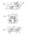
figure 1 représente un micro-interrupteur tel qu'utilisé dans le dispositif de commande de l'invention, - la
figure 2 représente en vue de dessus le micro-interrupteur de lafigure 1 sur lequel a été ajoutée une bobine planaire intégrée au substrat, - la
figure 3 montre une autre configuration du micro-interrupteur employé, - la
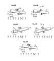
figure 4 montre un premier mode de réalisation du dispositif de commande de l'invention, - la
figure 5 montre un second mode de réalisation du dispositif de commande de l'invention. - les
figures 6A à 6E illustrent le fonctionnement du dispositif de commande de l'invention.
- the
figure 1 represents a microswitch as used in the control device of the invention, - the
figure 2 represents in top view the micro-switch of thefigure 1 on which was added a planar coil integrated in the substrate, - the
figure 3 shows another configuration of the micro-switch used, - the
figure 4 shows a first embodiment of the control device of the invention, - the
figure 5 shows a second embodiment of the control device of the invention. - the
Figures 6A to 6E illustrate the operation of the control device of the invention.
L'invention consiste à proposer un dispositif de commande 1, 1' doté de deux modes d'actionnement distinct. Ce type de dispositif de commande présente notamment un intérêt dans certaines applications qui seront précisées ci-après.The invention consists in providing a
Le dispositif de commande 1, 1' de l'invention fonctionne à l'aide d'un micro-interrupteur 2, 2' comportant un élément mobile pilotable par effet magnétique. Ce micro-interrupteur 2, 2' peut notamment être un MEMS (Micro-Electro Mechanical System) comportant une membrane 20, 20' dotée d'une couche ferromagnétique (par exemple en permalloy) et apte à s'aligner et s'orienter suivant les lignes de champ magnétique pour prendre deux états stables distincts, par exemple un état ouvert d'un circuit électrique et un état fermé du circuit électrique.The
Les
Dans la première configuration de micro-interrupteur 2 représentée en
Dans la deuxième configuration du micro-interrupteur 2' représentée en
Dans le dispositif de commande de l'invention 1, 1', une bobine d'excitation planaire 4 est intégrée au substrat du micro-interrupteur 2, 2' comme représentée sur la
En référence aux
L'aimant permanent mobile 11, 11' peut être actionné par l'intermédiaire d'un organe d'actionnement manuel (non représenté) pour former un bouton ou par l'intermédiaire d'un organe d'actionnement mécanique (non représenté) pour former un capteur de position.The movable
Lorsque l'aimant permanent mobile 11, 11' est en position de repos, la pièce fixe, constituée d'une pièce ferromagnétique ou de l'aimant permanent fixe 10, 10', et l'aimant permanent mobile 11, 11' génèrent donc entre eux un champ magnétique permanent uniforme B0 ayant des lignes de champ sensiblement parallèles entre elles. Comme la composante magnétique latérale générée dans la membrane 20, 20' par ce champ magnétique permanent uniforme B0 est faible, il est aisé de faire basculer la membrane vers son autre état en produisant une composante magnétique latérale opposée d'intensité supérieure.When the movable
Selon le sens de déplacement de l'aimant permanent mobile 11, 11', le dispositif de commande 1, 1' comporte deux modes de réalisation distincts. Ces deux modes de réalisation sont décrits avec une pièce fixe constituée d'un aimant permanent 10, 10'.According to the moving direction of the moving
Dans un premier mode de réalisation représenté sur la
Dans le second mode de réalisation de l'invention représenté en
Le fonctionnement d'un dispositif de commande 1, 1' du premier mode de réalisation ou du second mode de réalisation est explicité ci-dessous en liaison avec les
Sur la
Pour chacun des modes de réalisation décrit ci-dessus, le déplacement de l'aimant permanent mobile 11, 11' vers sa position de travail, génère une composante magnétique latérale Ba qui crée une composante BP2 dans la membrane 20 de manière à inverser le couple magnétique exercé sur la membrane et imposer le basculement de la membrane vers son autre état, c'est-à-dire l'état fermé (
L'aimant permanent mobile 11, 11' n'est destiné qu'à faire basculer la membrane que d'un état vers l'autre. Par conséquent, pour ramener la membrane dans son état initial, on utilise le second mode d'actionnement, c'est-à-dire la bobine d'excitation 4. Ce second mode d'actionnement présente l'avantage de pouvoir être actionné à distance par injection d'un courant dans la bobine 4 dans un sens approprié.The movable
En référence à la
Une fois le basculement de la membrane 20 effectué, l'alimentation en courant de la bobine 4 n'est plus nécessaire. Selon l'invention, le champ magnétique Bb n'est généré que de manière transitoire pour faire basculer la membrane 20 d'un état à l'autre. Sur la
Bien entendu, il faut comprendre que le dispositif de commande 1, 1' peut être commandé différemment. La membrane 20, 20' peut par exemple être initialement à l'état fermé. De même, le premier actionnement de la membrane peut être réalisé à l'aide de la bobine 4 et le second actionnement à l'aide de l'aimant permanent mobile 11, 11'. Selon les applications, toutes les configurations de fonctionnement sont donc possibles. Par ailleurs, le dispositif peut être configuré de manière à pouvoir fermer et ouvrir le circuit en utilisant uniquement l'aimant permanent mobile ou en utilisant uniquement la bobine en y injectant un courant positif ou un courant négatif.Of course, it should be understood that the
Une première application consiste par exemple à supprimer les courants de fuite ou de veille d'un système fonctionnant sur pile ou batterie et ainsi réaliser des économies d'énergie. Le dispositif de commande de l'invention permet de mettre le produit en marche manuellement en agissant sur l'aimant permanent mobile qui entraîne le basculement de la membrane de l'état ouvert initial à l'état fermé. Puis lorsque le système a fini sa tâche ou au bout d'une certaine durée, le produit peut se remettre en veille automatiquement par l'envoi d'un courant dans la bobine d'excitation du dispositif de commande pour faire basculer la membrane vers son état ouvert et ainsi ouvrir le circuit électrique. Le produit alimenté peut par exemple être un interrupteur sans fil ou une télécommande d'alarme ou d'ouverture de portes. L'emploi du dispositif de commande pour cette application permet notamment de garantir, au moment de la vente du produit, que la batterie ou la pile n'a pas été complètement déchargée par ses courants de veille.A first application is for example to eliminate the leakage current or standby of a system running on battery or battery and thus achieve energy savings. The control device of the invention allows the product to be manually turned on by acting on the movable permanent magnet which causes the membrane to switch from the initial open state to the closed state. Then when the system has finished its task or after a certain period of time, the product can go back to sleep automatically by sending a current in the excitation coil of the control device to switch the membrane to its open state and thus open the electrical circuit. The powered product may for example be a wireless switch or a remote control alarm or opening doors. The use of the control device for this application makes it possible in particular to guarantee, at the time of sale of the product, that the battery or the battery has not been completely discharged by its waking currents.
Une deuxième application du dispositif de commande de l'invention consiste par exemple à supprimer les courants de fuite des transformateurs pour les alimentations AC/DC destinées à alimenter ou recharger les appareils nomades tels que par exemple les téléphones portables, les baladeurs numériques ou les appareils photos. Les transformateurs de petite dimension présentent des rendements très bas qui conduisent à réaliser des alimentations secteurs qui consomment autant à vide que la charge qu'ils doivent alimenter. On utilise ainsi un dispositif de commande 1, 1' de l'invention pour couper automatiquement les courants de veille du système lors de la détection d'un faible courant de charge. En envoyant un courant dans la bobine d'excitation, la membrane bascule d'un état fermé à un état ouvert du circuit électrique. Pour remettre en marche le système, il suffit ensuite d'agir sur l'aimant permanent mobile par l'intermédiaire d'un bouton pour mettre la membrane dans son état de fermeture. Le même principe de commande peut par exemple être appliqué dans une troisième application.A second application of the control device of the invention consists, for example, in eliminating transformer leakage currents for AC / DC power supplies intended to power or charge mobile devices such as, for example, mobile telephones, digital music players or devices. Pictures. Small transformers have very low yields that lead to producing power sectors that consume as much empty as the load they must feed. Thus, a
Cette troisième application consiste à utiliser le dispositif de commande de l'invention dans un disjoncteur. Sur détection d'un défaut, le courant est coupé automatiquement en envoyant un courant dans la bobine d'excitation qui fait basculer la membrane de l'état fermé à l'état ouvert. Pour refermer le circuit électrique, l'actionnement de l'aimant permanent mobile permet de refaire passer la membrane de son état ouvert à son état fermé.This third application consists in using the control device of the invention in a circuit breaker. On detection of a fault, the current is cut off automatically by sending a current into the excitation coil which switches the membrane from the closed state to the open state. To close the electrical circuit, the actuation of the movable permanent magnet makes it possible to pass the membrane from its open state to its closed state.
Une dernière application peut par exemple consister à utiliser le dispositif de commande dans un capteur, par exemple sans fil et autonome, apte à dialoguer par liaison sans fil avec un organe émetteur/récepteur principal. Le dispositif de l'invention permet par exemple de couper le capteur une fois qu'une transmission de données est effectuée.A last application may for example consist in using the control device in a sensor, for example wireless and autonomous, able to communicate wirelessly with a transmitter / receiver main member. The device of the invention allows for example to cut the sensor once a data transmission is performed.
Il est bien entendu que l'on peut, sans sortir du cadre de l'invention, imaginer d'autres variantes et perfectionnements de détail et de même envisager l'emploi de moyens équivalents.It is understood that one can, without departing from the scope of the invention, imagine other variants and refinements of detail and even consider the use of equivalent means.
Claims (14)
- Control device (1, 1') of an electrical circuit comprising:- a microswitch (2, 2') comprising a moving element that can be driven by magnetic effect between a first stable state and a second stable state to control the electrical circuit,- a fixed part made of magnetic material (10, 10'),
andcharacterized in that it comprises as well:- a moving permanent magnet (11, 11') that can be actuated between a first position, in which it forms, with the fixed part (10, 10'), a substantially uniform permanent magnetic field (B0) holding the moving element in the first state or the second state, and a second position in which it is able to control the switchover of the moving element from one state to the other,- an excitation coil (4) able to create a temporary magnetic field (Bb) able to cause the moving element to switch over from one state to the other when the moving permanent magnet (11, 11') is in the first position. - Device according to Claim 1,characterized in that the fixed element made of magnetic material is a permanent magnet (10, 10').
- Device according to Claim 2,characterized in that the moving permanent magnet (11, 11') and the fixed permanent magnet (10, 10') have magnetizations (M0, M1' M0', M1') of parallel direction and of the same direction.
- Device according to Claim 3,characterized in that the magnetic field (Bb) created by the coil (4) is substantially perpendicular to the magnetization directions of the fixed (10, 10') and moving (11, 11') permanent magnets.
- Device according to Claim 3 or 4,characterized in that the moving permanent magnet (11, 11') is able to be moved perpendicularly to its direction of magnetization (M1, M1').
- Device according to Claim 5,characterized in that the microswitch (2, 2') is centred relative to the fixed and moving permanent magnets.
- Device according to Claim 3 or 4,characterized in that the moving permanent magnet (11, 11') is able to be moved parallel to its direction of magnetization (M1, M1').
- Device according to Claim 7,characterized in that the microswitch (2, 2') is off-centred relative to the fixed and moving permanent magnets.
- Device according to one of Claims 1 to 8,characterized in that the moving element of the microswitch (2, 2') is a ferromagnetic membrane (20, 20') that can be oriented along magnetic field lines.
- Device according to one of Claims 1 to 9,characterized in that, after actuation, the moving permanent magnet (11, 11') is automatically returned from its second position to its first position.
- Device according to one of Claims 1 to 10,characterized in that:- the moving element is initially held in the first state, then- the moving element is switched over to the second state by movement of the moving permanent magnet to its second position,- the moving element is returned to its first state by activation of the coil once the moving permanent magnet has returned to its first position.
- Device according to Claim 11,characterized in that the first state of the moving element is an open state in which the electrical circuit is open andin that the second state is a closed state in which the electrical circuit is closed.
- Use of the device (1, 1') according to Claim 12, to eliminate the leakage or standby currents in a system by disconnecting the electrical circuit by activation of the coil (4) and by re-engaging the electrical circuit using the moving permanent magnet (11, 11').
- Use of the device (1, 1') according to Claim 12 in a circuit breaker to automatically disconnect the electrical circuit in the case of an electrical fault using the excitation coil (4) and then manually reclose the electrical circuit using the moving permanent magnet (11, 11').
Applications Claiming Priority (1)
| Application Number | Priority Date | Filing Date | Title |
|---|---|---|---|
| FR0850574AFR2926922B1 (en) | 2008-01-30 | 2008-01-30 | CONTROL DEVICE WITH DOUBLE ACTUATION MODE |
Publications (2)
| Publication Number | Publication Date |
|---|---|
| EP2085987A1 EP2085987A1 (en) | 2009-08-05 |
| EP2085987B1true EP2085987B1 (en) | 2015-03-04 |
Family
ID=39592735
Family Applications (1)
| Application Number | Title | Priority Date | Filing Date |
|---|---|---|---|
| EP09150415.9ANot-in-forceEP2085987B1 (en) | 2008-01-30 | 2009-01-13 | Dual-actuation-mode control device |
Country Status (3)
| Country | Link |
|---|---|
| US (1) | US7982563B2 (en) |
| EP (1) | EP2085987B1 (en) |
| FR (1) | FR2926922B1 (en) |
Families Citing this family (5)
| Publication number | Priority date | Publication date | Assignee | Title |
|---|---|---|---|---|
| KR101434280B1 (en)* | 2008-03-20 | 2014-09-05 | 에이치티 마이크로아날리티칼 아이엔씨 | Integrated reed switch |
| US8665041B2 (en)* | 2008-03-20 | 2014-03-04 | Ht Microanalytical, Inc. | Integrated microminiature relay |
| FR2970596B1 (en) | 2011-01-19 | 2013-02-08 | Commissariat Energie Atomique | CONTACTOR AND SWITCH |
| IES20110389A2 (en)* | 2011-09-06 | 2013-03-13 | Atreus Entpr Ltd | Leakage current detector |
| JP7397253B2 (en) | 2018-09-20 | 2023-12-13 | Ignite株式会社 | MEMS display device with automatic inspection mechanism |
Family Cites Families (10)
| Publication number | Priority date | Publication date | Assignee | Title |
|---|---|---|---|---|
| CA2211830C (en)* | 1997-08-22 | 2002-08-13 | Cindy Xing Qiu | Miniature electromagnetic microwave switches and switch arrays |
| US6469602B2 (en) | 1999-09-23 | 2002-10-22 | Arizona State University | Electronically switching latching micro-magnetic relay and method of operating same |
| US6794965B2 (en)* | 2001-01-18 | 2004-09-21 | Arizona State University | Micro-magnetic latching switch with relaxed permanent magnet alignment requirements |
| US20030025580A1 (en)* | 2001-05-18 | 2003-02-06 | Microlab, Inc. | Apparatus utilizing latching micromagnetic switches |
| FR2880730A1 (en)* | 2005-01-10 | 2006-07-14 | Schneider Electric Ind Sas | Microsystem for use as e.g. switch, has permanent magnet moved by push-button to control, by magnetic effect, movement of membrane of movable unit between two positions, each corresponding to opening or closing of electric circuit |
| DE602006011918D1 (en)* | 2005-06-06 | 2010-03-11 | Schneider Electric Ind Sas | DEVICE FOR SWITCHING ON AN ELECTRIC SHAMANE MAGNET |
| GB0514869D0 (en)* | 2005-07-20 | 2005-08-24 | Eja Ltd | Safety switch |
| US7482899B2 (en)* | 2005-10-02 | 2009-01-27 | Jun Shen | Electromechanical latching relay and method of operating same |
| FR2899720B1 (en)* | 2006-04-11 | 2008-10-17 | Schneider Electric Ind Sas | MICROSYSTEM FOR SWITCHING A POWER ELECTRIC CIRCUIT |
| FR2903807B1 (en)* | 2006-07-12 | 2009-10-09 | Schneider Electric Ind Sas | SWITCHING DEVICE INCLUDING A MOBILE FERROMAGNETIC PART |
- 2008
- 2008-01-30FRFR0850574Apatent/FR2926922B1/ennot_activeExpired - Fee Related
- 2009
- 2009-01-13EPEP09150415.9Apatent/EP2085987B1/ennot_activeNot-in-force
- 2009-01-23USUS12/358,538patent/US7982563B2/ennot_activeExpired - Fee Related
Also Published As
| Publication number | Publication date |
|---|---|
| US7982563B2 (en) | 2011-07-19 |
| US20090189720A1 (en) | 2009-07-30 |
| FR2926922B1 (en) | 2010-02-19 |
| EP2085987A1 (en) | 2009-08-05 |
| FR2926922A1 (en) | 2009-07-31 |
Similar Documents
| Publication | Publication Date | Title |
|---|---|---|
| EP1556873B1 (en) | Electrical switching device, relay and electrical apparatus comprising same | |
| CA2767166C (en) | Wireless switching device | |
| EP2085987B1 (en) | Dual-actuation-mode control device | |
| EP2072959B1 (en) | Device with contactless adjustment means | |
| EP2779190B1 (en) | Individual switching block and switching device comprising at least one such block | |
| EP2899343B1 (en) | Anti-remanence device for electromagnetic lock | |
| EP1925008B1 (en) | Electric circuit switching device using at least two permanent magnets | |
| WO2011069879A1 (en) | Electric energy generating device | |
| EP1836714B1 (en) | Microsystem with electromagnetic control | |
| EP2041765A1 (en) | Switching device including a moving ferromagnetic part | |
| EP2022069B1 (en) | Device for detecting the three states of a circuit breaker | |
| EP2328132B1 (en) | Remote control device | |
| EP1901325B1 (en) | Switching device including magnetic microswitches organized in a matrix | |
| FR2951316A1 (en) | Rotary bistable actuator, has magnet generating maintain magnetic flux to maintain reinforcement in one of two stable positions, where magnet is in contact with two magnetic parts so as to polarize reinforcement along longitudinal axis | |
| FR2880730A1 (en) | Microsystem for use as e.g. switch, has permanent magnet moved by push-button to control, by magnetic effect, movement of membrane of movable unit between two positions, each corresponding to opening or closing of electric circuit | |
| EP1836713B1 (en) | Microsystem with integrated reluctant magnetic circuit | |
| EP1889275B1 (en) | Electric circuit switching device using a movable toroidal magnet | |
| FR2886758A1 (en) | Electric circuit switching device for use as e.g. push button, has permanent magnets oppositely disposed and presenting radial symmetry, where one magnet is integrated in translation to actuating button | |
| FR2909218A1 (en) | ELECTRIC SWITCHING MODULE WITH ELECTRONIC COMPONENTS OF CMS TYPE | |
| WO2007115945A1 (en) | Microsystem for switching a power electric circuit | |
| FR2892226A1 (en) | Electric circuit e.g. sliding button, switching device for rescue system, has movable permanent magnet linked to actuating unit whose position is modified to modify direction of magnetic field lines produced by movable and fixed magnets | |
| FR2883274A1 (en) | Microelectromechanical system e.g. microswitch, has magnetic circuit applying additional contact force to mobile contact part, and opening circuit applying opening force to contact part after control for opening electric circuit | |
| FR2976398A1 (en) | ELECTROMAGNETIC ACTUATING DEVICE EMPLOYED IN AN ELECTRIC SWITCH DEVICE. |
Legal Events
| Date | Code | Title | Description |
|---|---|---|---|
| PUAI | Public reference made under article 153(3) epc to a published international application that has entered the european phase | Free format text:ORIGINAL CODE: 0009012 | |
| AK | Designated contracting states | Kind code of ref document:A1 Designated state(s):AT BE BG CH CY CZ DE DK EE ES FI FR GB GR HR HU IE IS IT LI LT LU LV MC MK MT NL NO PL PT RO SE SI SK TR | |
| AX | Request for extension of the european patent | Extension state:AL BA RS | |
| 17P | Request for examination filed | Effective date:20100111 | |
| 17Q | First examination report despatched | Effective date:20100225 | |
| AKX | Designation fees paid | Designated state(s):AT BE BG CH CY CZ DE DK EE ES FI FR GB GR HR HU IE IS IT LI LT LU LV MC MK MT NL NO PL PT RO SE SI SK TR | |
| GRAP | Despatch of communication of intention to grant a patent | Free format text:ORIGINAL CODE: EPIDOSNIGR1 | |
| INTG | Intention to grant announced | Effective date:20141208 | |
| GRAS | Grant fee paid | Free format text:ORIGINAL CODE: EPIDOSNIGR3 | |
| GRAA | (expected) grant | Free format text:ORIGINAL CODE: 0009210 | |
| AK | Designated contracting states | Kind code of ref document:B1 Designated state(s):AT BE BG CH CY CZ DE DK EE ES FI FR GB GR HR HU IE IS IT LI LT LU LV MC MK MT NL NO PL PT RO SE SI SK TR | |
| REG | Reference to a national code | Ref country code:GB Ref legal event code:FG4D Free format text:NOT ENGLISH | |
| REG | Reference to a national code | Ref country code:CH Ref legal event code:EP | |
| REG | Reference to a national code | Ref country code:IE Ref legal event code:FG4D Free format text:LANGUAGE OF EP DOCUMENT: FRENCH | |
| REG | Reference to a national code | Ref country code:AT Ref legal event code:REF Ref document number:714483 Country of ref document:AT Kind code of ref document:T Effective date:20150415 | |
| REG | Reference to a national code | Ref country code:DE Ref legal event code:R096 Ref document number:602009029714 Country of ref document:DE Effective date:20150416 | |
| REG | Reference to a national code | Ref country code:AT Ref legal event code:MK05 Ref document number:714483 Country of ref document:AT Kind code of ref document:T Effective date:20150304 Ref country code:NL Ref legal event code:VDEP Effective date:20150304 | |
| PG25 | Lapsed in a contracting state [announced via postgrant information from national office to epo] | Ref country code:FI Free format text:LAPSE BECAUSE OF FAILURE TO SUBMIT A TRANSLATION OF THE DESCRIPTION OR TO PAY THE FEE WITHIN THE PRESCRIBED TIME-LIMIT Effective date:20150304 Ref country code:HR Free format text:LAPSE BECAUSE OF FAILURE TO SUBMIT A TRANSLATION OF THE DESCRIPTION OR TO PAY THE FEE WITHIN THE PRESCRIBED TIME-LIMIT Effective date:20150304 Ref country code:ES Free format text:LAPSE BECAUSE OF FAILURE TO SUBMIT A TRANSLATION OF THE DESCRIPTION OR TO PAY THE FEE WITHIN THE PRESCRIBED TIME-LIMIT Effective date:20150304 Ref country code:SE Free format text:LAPSE BECAUSE OF FAILURE TO SUBMIT A TRANSLATION OF THE DESCRIPTION OR TO PAY THE FEE WITHIN THE PRESCRIBED TIME-LIMIT Effective date:20150304 Ref country code:NO Free format text:LAPSE BECAUSE OF FAILURE TO SUBMIT A TRANSLATION OF THE DESCRIPTION OR TO PAY THE FEE WITHIN THE PRESCRIBED TIME-LIMIT Effective date:20150604 Ref country code:LT Free format text:LAPSE BECAUSE OF FAILURE TO SUBMIT A TRANSLATION OF THE DESCRIPTION OR TO PAY THE FEE WITHIN THE PRESCRIBED TIME-LIMIT Effective date:20150304 | |
| REG | Reference to a national code | Ref country code:LT Ref legal event code:MG4D | |
| PG25 | Lapsed in a contracting state [announced via postgrant information from national office to epo] | Ref country code:GR Free format text:LAPSE BECAUSE OF FAILURE TO SUBMIT A TRANSLATION OF THE DESCRIPTION OR TO PAY THE FEE WITHIN THE PRESCRIBED TIME-LIMIT Effective date:20150605 Ref country code:LV Free format text:LAPSE BECAUSE OF FAILURE TO SUBMIT A TRANSLATION OF THE DESCRIPTION OR TO PAY THE FEE WITHIN THE PRESCRIBED TIME-LIMIT Effective date:20150304 Ref country code:AT Free format text:LAPSE BECAUSE OF FAILURE TO SUBMIT A TRANSLATION OF THE DESCRIPTION OR TO PAY THE FEE WITHIN THE PRESCRIBED TIME-LIMIT Effective date:20150304 | |
| PG25 | Lapsed in a contracting state [announced via postgrant information from national office to epo] | Ref country code:NL Free format text:LAPSE BECAUSE OF FAILURE TO SUBMIT A TRANSLATION OF THE DESCRIPTION OR TO PAY THE FEE WITHIN THE PRESCRIBED TIME-LIMIT Effective date:20150304 | |
| PG25 | Lapsed in a contracting state [announced via postgrant information from national office to epo] | Ref country code:EE Free format text:LAPSE BECAUSE OF FAILURE TO SUBMIT A TRANSLATION OF THE DESCRIPTION OR TO PAY THE FEE WITHIN THE PRESCRIBED TIME-LIMIT Effective date:20150304 Ref country code:CZ Free format text:LAPSE BECAUSE OF FAILURE TO SUBMIT A TRANSLATION OF THE DESCRIPTION OR TO PAY THE FEE WITHIN THE PRESCRIBED TIME-LIMIT Effective date:20150304 Ref country code:PT Free format text:LAPSE BECAUSE OF FAILURE TO SUBMIT A TRANSLATION OF THE DESCRIPTION OR TO PAY THE FEE WITHIN THE PRESCRIBED TIME-LIMIT Effective date:20150706 Ref country code:RO Free format text:LAPSE BECAUSE OF FAILURE TO SUBMIT A TRANSLATION OF THE DESCRIPTION OR TO PAY THE FEE WITHIN THE PRESCRIBED TIME-LIMIT Effective date:20150304 Ref country code:SK Free format text:LAPSE BECAUSE OF FAILURE TO SUBMIT A TRANSLATION OF THE DESCRIPTION OR TO PAY THE FEE WITHIN THE PRESCRIBED TIME-LIMIT Effective date:20150304 | |
| PG25 | Lapsed in a contracting state [announced via postgrant information from national office to epo] | Ref country code:PL Free format text:LAPSE BECAUSE OF FAILURE TO SUBMIT A TRANSLATION OF THE DESCRIPTION OR TO PAY THE FEE WITHIN THE PRESCRIBED TIME-LIMIT Effective date:20150304 Ref country code:IS Free format text:LAPSE BECAUSE OF FAILURE TO SUBMIT A TRANSLATION OF THE DESCRIPTION OR TO PAY THE FEE WITHIN THE PRESCRIBED TIME-LIMIT Effective date:20150704 | |
| REG | Reference to a national code | Ref country code:DE Ref legal event code:R097 Ref document number:602009029714 Country of ref document:DE Ref country code:FR Ref legal event code:PLFP Year of fee payment:8 | |
| PG25 | Lapsed in a contracting state [announced via postgrant information from national office to epo] | Ref country code:IT Free format text:LAPSE BECAUSE OF FAILURE TO SUBMIT A TRANSLATION OF THE DESCRIPTION OR TO PAY THE FEE WITHIN THE PRESCRIBED TIME-LIMIT Effective date:20150304 | |
| PLBE | No opposition filed within time limit | Free format text:ORIGINAL CODE: 0009261 | |
| STAA | Information on the status of an ep patent application or granted ep patent | Free format text:STATUS: NO OPPOSITION FILED WITHIN TIME LIMIT | |
| PG25 | Lapsed in a contracting state [announced via postgrant information from national office to epo] | Ref country code:DK Free format text:LAPSE BECAUSE OF FAILURE TO SUBMIT A TRANSLATION OF THE DESCRIPTION OR TO PAY THE FEE WITHIN THE PRESCRIBED TIME-LIMIT Effective date:20150304 | |
| 26N | No opposition filed | Effective date:20151207 | |
| PG25 | Lapsed in a contracting state [announced via postgrant information from national office to epo] | Ref country code:SI Free format text:LAPSE BECAUSE OF FAILURE TO SUBMIT A TRANSLATION OF THE DESCRIPTION OR TO PAY THE FEE WITHIN THE PRESCRIBED TIME-LIMIT Effective date:20150304 | |
| PG25 | Lapsed in a contracting state [announced via postgrant information from national office to epo] | Ref country code:BE Free format text:LAPSE BECAUSE OF NON-PAYMENT OF DUE FEES Effective date:20160131 | |
| PG25 | Lapsed in a contracting state [announced via postgrant information from national office to epo] | Ref country code:LU Free format text:LAPSE BECAUSE OF FAILURE TO SUBMIT A TRANSLATION OF THE DESCRIPTION OR TO PAY THE FEE WITHIN THE PRESCRIBED TIME-LIMIT Effective date:20160113 | |
| REG | Reference to a national code | Ref country code:CH Ref legal event code:PL | |
| PG25 | Lapsed in a contracting state [announced via postgrant information from national office to epo] | Ref country code:MC Free format text:LAPSE BECAUSE OF FAILURE TO SUBMIT A TRANSLATION OF THE DESCRIPTION OR TO PAY THE FEE WITHIN THE PRESCRIBED TIME-LIMIT Effective date:20150304 | |
| PG25 | Lapsed in a contracting state [announced via postgrant information from national office to epo] | Ref country code:LI Free format text:LAPSE BECAUSE OF NON-PAYMENT OF DUE FEES Effective date:20160131 Ref country code:CH Free format text:LAPSE BECAUSE OF NON-PAYMENT OF DUE FEES Effective date:20160131 | |
| REG | Reference to a national code | Ref country code:IE Ref legal event code:MM4A | |
| REG | Reference to a national code | Ref country code:FR Ref legal event code:PLFP Year of fee payment:9 | |
| PG25 | Lapsed in a contracting state [announced via postgrant information from national office to epo] | Ref country code:IE Free format text:LAPSE BECAUSE OF NON-PAYMENT OF DUE FEES Effective date:20160113 | |
| PGFP | Annual fee paid to national office [announced via postgrant information from national office to epo] | Ref country code:GB Payment date:20170120 Year of fee payment:9 | |
| PG25 | Lapsed in a contracting state [announced via postgrant information from national office to epo] | Ref country code:MT Free format text:LAPSE BECAUSE OF FAILURE TO SUBMIT A TRANSLATION OF THE DESCRIPTION OR TO PAY THE FEE WITHIN THE PRESCRIBED TIME-LIMIT Effective date:20150304 | |
| REG | Reference to a national code | Ref country code:FR Ref legal event code:PLFP Year of fee payment:10 | |
| PGFP | Annual fee paid to national office [announced via postgrant information from national office to epo] | Ref country code:FR Payment date:20171211 Year of fee payment:10 | |
| PGFP | Annual fee paid to national office [announced via postgrant information from national office to epo] | Ref country code:DE Payment date:20171211 Year of fee payment:10 | |
| PG25 | Lapsed in a contracting state [announced via postgrant information from national office to epo] | Ref country code:CY Free format text:LAPSE BECAUSE OF FAILURE TO SUBMIT A TRANSLATION OF THE DESCRIPTION OR TO PAY THE FEE WITHIN THE PRESCRIBED TIME-LIMIT Effective date:20150304 Ref country code:HU Free format text:LAPSE BECAUSE OF FAILURE TO SUBMIT A TRANSLATION OF THE DESCRIPTION OR TO PAY THE FEE WITHIN THE PRESCRIBED TIME-LIMIT; INVALID AB INITIO Effective date:20090113 | |
| PG25 | Lapsed in a contracting state [announced via postgrant information from national office to epo] | Ref country code:MK Free format text:LAPSE BECAUSE OF FAILURE TO SUBMIT A TRANSLATION OF THE DESCRIPTION OR TO PAY THE FEE WITHIN THE PRESCRIBED TIME-LIMIT Effective date:20150304 Ref country code:TR Free format text:LAPSE BECAUSE OF FAILURE TO SUBMIT A TRANSLATION OF THE DESCRIPTION OR TO PAY THE FEE WITHIN THE PRESCRIBED TIME-LIMIT Effective date:20150304 | |
| PG25 | Lapsed in a contracting state [announced via postgrant information from national office to epo] | Ref country code:BG Free format text:LAPSE BECAUSE OF FAILURE TO SUBMIT A TRANSLATION OF THE DESCRIPTION OR TO PAY THE FEE WITHIN THE PRESCRIBED TIME-LIMIT Effective date:20150304 | |
| GBPC | Gb: european patent ceased through non-payment of renewal fee | Effective date:20180113 | |
| PG25 | Lapsed in a contracting state [announced via postgrant information from national office to epo] | Ref country code:GB Free format text:LAPSE BECAUSE OF NON-PAYMENT OF DUE FEES Effective date:20180113 | |
| REG | Reference to a national code | Ref country code:DE Ref legal event code:R119 Ref document number:602009029714 Country of ref document:DE | |
| PG25 | Lapsed in a contracting state [announced via postgrant information from national office to epo] | Ref country code:FR Free format text:LAPSE BECAUSE OF NON-PAYMENT OF DUE FEES Effective date:20190131 Ref country code:DE Free format text:LAPSE BECAUSE OF NON-PAYMENT OF DUE FEES Effective date:20190801 |