EP2084446B1 - Tubular connection - Google Patents
Tubular connectionDownload PDFInfo
- Publication number
- EP2084446B1 EP2084446B1EP07866452.1AEP07866452AEP2084446B1EP 2084446 B1EP2084446 B1EP 2084446B1EP 07866452 AEP07866452 AEP 07866452AEP 2084446 B1EP2084446 B1EP 2084446B1
- Authority
- EP
- European Patent Office
- Prior art keywords
- locking element
- joint according
- tubular joint
- extrusion
- seal
- Prior art date
- Legal status (The legal status is an assumption and is not a legal conclusion. Google has not performed a legal analysis and makes no representation as to the accuracy of the status listed.)
- Active
Links
- 238000001125extrusionMethods0.000claimsdescription66
- 239000000463materialSubstances0.000claimsdescription9
- -1polyethylenePolymers0.000claimsdescription8
- 125000006850spacer groupChemical group0.000claimsdescription8
- 230000035515penetrationEffects0.000claimsdescription7
- 230000000694effectsEffects0.000claimsdescription6
- 239000002184metalSubstances0.000claimsdescription5
- 229910052751metalInorganic materials0.000claimsdescription5
- 239000004033plasticSubstances0.000claimsdescription5
- 229920003023plasticPolymers0.000claimsdescription5
- 239000004952PolyamideSubstances0.000claimsdescription4
- 229920002647polyamidePolymers0.000claimsdescription4
- 239000004698PolyethyleneSubstances0.000claimsdescription3
- 239000004743PolypropyleneSubstances0.000claimsdescription3
- 229920000573polyethylenePolymers0.000claimsdescription3
- 229920001155polypropylenePolymers0.000claimsdescription3
- 239000012858resilient materialSubstances0.000claims1
- 229920001971elastomerPolymers0.000description15
- 239000000806elastomerSubstances0.000description14
- 238000003780insertionMethods0.000description5
- 230000037431insertionEffects0.000description5
- 238000007789sealingMethods0.000description5
- 238000004873anchoringMethods0.000description4
- 210000002445nippleAnatomy0.000description4
- 238000004519manufacturing processMethods0.000description3
- 239000012530fluidSubstances0.000description2
- 229910001018Cast ironInorganic materials0.000description1
- 229910000760Hardened steelInorganic materials0.000description1
- 229910001209Low-carbon steelInorganic materials0.000description1
- 230000001154acute effectEffects0.000description1
- 238000004026adhesive bondingMethods0.000description1
- 239000011230binding agentSubstances0.000description1
- 239000007767bonding agentSubstances0.000description1
- 238000006243chemical reactionMethods0.000description1
- 239000003795chemical substances by applicationSubstances0.000description1
- 230000000295complement effectEffects0.000description1
- 239000002131composite materialSubstances0.000description1
- 230000006835compressionEffects0.000description1
- 238000007906compressionMethods0.000description1
- 238000006073displacement reactionMethods0.000description1
- 239000003651drinking waterSubstances0.000description1
- 235000020188drinking waterNutrition0.000description1
- 239000013013elastic materialSubstances0.000description1
- 238000002347injectionMethods0.000description1
- 239000007924injectionSubstances0.000description1
- 238000000034methodMethods0.000description1
- 238000000465mouldingMethods0.000description1
- 230000000750progressive effectEffects0.000description1
- 239000011253protective coatingSubstances0.000description1
- 239000011241protective layerSubstances0.000description1
- 230000000284resting effectEffects0.000description1
- 238000010079rubber tappingMethods0.000description1
- 238000000926separation methodMethods0.000description1
- 239000007787solidSubstances0.000description1
- 239000002351wastewaterSubstances0.000description1
Images


Classifications
- F—MECHANICAL ENGINEERING; LIGHTING; HEATING; WEAPONS; BLASTING
- F16—ENGINEERING ELEMENTS AND UNITS; GENERAL MEASURES FOR PRODUCING AND MAINTAINING EFFECTIVE FUNCTIONING OF MACHINES OR INSTALLATIONS; THERMAL INSULATION IN GENERAL
- F16L—PIPES; JOINTS OR FITTINGS FOR PIPES; SUPPORTS FOR PIPES, CABLES OR PROTECTIVE TUBING; MEANS FOR THERMAL INSULATION IN GENERAL
- F16L37/00—Couplings of the quick-acting type
- F16L37/08—Couplings of the quick-acting type in which the connection between abutting or axially overlapping ends is maintained by locking members
- F16L37/084—Couplings of the quick-acting type in which the connection between abutting or axially overlapping ends is maintained by locking members combined with automatic locking
- F16L37/0845—Couplings of the quick-acting type in which the connection between abutting or axially overlapping ends is maintained by locking members combined with automatic locking by means of retaining members associated with the packing member
- F—MECHANICAL ENGINEERING; LIGHTING; HEATING; WEAPONS; BLASTING
- F16—ENGINEERING ELEMENTS AND UNITS; GENERAL MEASURES FOR PRODUCING AND MAINTAINING EFFECTIVE FUNCTIONING OF MACHINES OR INSTALLATIONS; THERMAL INSULATION IN GENERAL
- F16L—PIPES; JOINTS OR FITTINGS FOR PIPES; SUPPORTS FOR PIPES, CABLES OR PROTECTIVE TUBING; MEANS FOR THERMAL INSULATION IN GENERAL
- F16L17/00—Joints with packing adapted to sealing by fluid pressure
- F16L17/02—Joints with packing adapted to sealing by fluid pressure with sealing rings arranged between outer surface of pipe and inner surface of sleeve or socket
- F16L17/03—Joints with packing adapted to sealing by fluid pressure with sealing rings arranged between outer surface of pipe and inner surface of sleeve or socket having annular axial lips
- F16L17/035—Joints with packing adapted to sealing by fluid pressure with sealing rings arranged between outer surface of pipe and inner surface of sleeve or socket having annular axial lips the sealing rings having two lips parallel to each other
- F—MECHANICAL ENGINEERING; LIGHTING; HEATING; WEAPONS; BLASTING
- F16—ENGINEERING ELEMENTS AND UNITS; GENERAL MEASURES FOR PRODUCING AND MAINTAINING EFFECTIVE FUNCTIONING OF MACHINES OR INSTALLATIONS; THERMAL INSULATION IN GENERAL
- F16L—PIPES; JOINTS OR FITTINGS FOR PIPES; SUPPORTS FOR PIPES, CABLES OR PROTECTIVE TUBING; MEANS FOR THERMAL INSULATION IN GENERAL
- F16L21/00—Joints with sleeve or socket
- F16L21/08—Joints with sleeve or socket with additional locking means
Definitions
- the socket end 4comprises a fastening flange 14 for assembly with a pipe element (not shown) provided with a corresponding flange, and a free end 16, turned towards the spigot end 6 in the non-state. assembled.
- the interlocking end 4further comprises an inner annular groove 18 (see FIG. Figure 2 ).
- the inner groove 18has a cross section substantially in a circular arc, but it may have other shapes, for example a rectangular section. It forms a groove wall inclined with respect to the central axis XX.
- the wall 20has a frustoconical shape and narrows towards the free end 16 of the interlocking end. It forms an angle ⁇ with the central axis XX, between 10 ° and 55 °.
Landscapes
- Engineering & Computer Science (AREA)
- General Engineering & Computer Science (AREA)
- Mechanical Engineering (AREA)
- Physics & Mathematics (AREA)
- Fluid Mechanics (AREA)
- Joints With Sleeves (AREA)
- Quick-Acting Or Multi-Walled Pipe Joints (AREA)
- Gasket Seals (AREA)
Description
Translated fromFrenchLa présente invention concerne une jonction tubulaire, du type indiqué dans le préambule de la revendication 1.The present invention relates to a tubular junction, of the type indicated in the preamble of claim 1.
Une telle jonction est connue de
Elle s'applique notamment aux canalisations transportant de l'eau potable ou des eaux usées pour l'assainissement.It applies in particular to pipelines carrying drinking water or wastewater for sanitation.
On connaît dans l'état de la technique de telles jonctions tubulaires. Lorsque la jonction tubulaire est à l'état posé et lors de l'exploitation de la canalisation, un fluide sous pression circule dans les éléments de canalisation. Sous l'action du fluide sous pression le bout uni et le bout à emboîtement ont tendance à se séparer l'un de l'autre. De plus, la garniture d'étanchéité risque d'être extrudée, voire expulsée entre le bout à emboîtement et le bout uni.In the state of the art, such tubular junctions are known. When the tubular junction is in the set state and during the operation of the pipe, a pressurized fluid circulates in the pipe elements. Under the action of pressurized fluid the spigot end and the socket end tend to separate from each other. In addition, the seal may be extruded or expelled between the nipple and the spigot end.
Les jonctions tubulaires connues comportent des éléments de verrouillage qui sont adaptés pour verrouiller le bout uni par rapport au bout à emboîtement et empêcher ainsi la séparation axiale entre les éléments de canalisation assemblés.The known tubular junctions comprise locking elements which are adapted to lock the spigot with respect to the interlocking end and thus prevent the axial separation between the assembled pipe elements.
On connaît d'une part des éléments de verrouillage qui coopèrent exclusivement à coulissement avec la gorge intérieure du bout à emboîtement. Toutefois, dans le cas d'un jeu faible entre le bout à emboîtement et le bout uni, ces éléments de verrouillage nécessitent une force importante d'emboîtage étant donné que le déplacement axial des éléments de verrouillage lors de l'insertion du bout uni nécessite la compression d'un volume important d'élastomère. De plus, ces jonctions tubulaires ne permettent pas un décalage angulaire important entre le bout uni et le bout à emboîtement.Known on the one hand locking elements that cooperate exclusively sliding with the inner groove of the interlocking end. However, in the case of a weak clearance between the interlocking end and the spigot, these locking elements require a large casing force since the axial displacement of the locking elements during insertion of the spigot requires the compression of a large volume of elastomer. In addition, these tubular junctions do not allow a large angular offset between the spigot end and the socket end.
En outre, on connaît des éléments de verrouillage noyés dans l'élastomère et fonctionnant exclusivement par un arc-boutement entre le bout uni et le bout à emboîtement au moyen d'un basculement de l'élément de verrouillage. Ces éléments de verrouillage nécessitent alors des forces d'emboîtage importantes dans le cas d'un jeu faible entre le bout à emboîtement et le bout uni. De plus, il existe le risque, lorsque le jeu entre les éléments de canalisation est important et lorsque la pression interne est élevée, que l'élément de verrouillage ne résiste pas au recul du bout uni et se retourne complètement, rendant alors le verrouillage inopérant.In addition, there are known locking elements embedded in the elastomer and operating exclusively by a bracing between the spigot end and the socket end by means of a tilting of the locking element. These locking elements then require significant nesting forces in the case of a weak clearance between the nipple and the spigot. In addition, there is the risk, when the clearance between the pipe elements is important and when the internal pressure is high, that the element The lock does not resist the recoil of the spigot and turns completely, making the lock inoperative.
L'invention a pour but de pallier ces inconvénients et de proposer une jonction tubulaire qui permet à la fois de réduire les forces d'emboîtage du bout uni dans le bout à emboîtement et un verrouillage efficace dans une large gamme de jeux.The object of the invention is to overcome these drawbacks and to propose a tubular junction which makes it possible at the same time to reduce the interlocking forces of the spigot end in the interlocking end and an effective locking in a wide range of games.
A cet effet, l'invention a pour objet une jonction tubulaire du type indiqué, caractérisé par les caractéristiques de la partie caractérisante de la revendication 1.For this purpose, the subject of the invention is a tubular junction of the type indicated, characterized by the characteristics of the characterizing part of claim 1.
Selon des modes particuliers de réalisation, la jonction tubulaire comporte l'une ou plusieurs des caractéristiques suivantes :
- lorsque le jeu est dans la première gamme de jeux, la face d'application est adaptée pour s'appliquer à plat et pour glisser sur la paroi de gorge lors du recul du bout uni par rapport au bout à emboîtement dans le sens tendant à sortir le bout uni du bout à emboîtement, l'élément de verrouillage se déplaçant axialement vers l'extrémité libre et radialement vers l'intérieur par glissement de la face d'application sur la paroi de gorge ;
- lorsque la face d'application de l'élément de verrouillage s'applique contre la paroi de gorge, la dent d'accrochage principale s'étend sensiblement radialement vers l'intérieur par rapport à l'axe central ;
- l'élément de verrouillage comporte une face intérieure qui, lorsque le jeu radial est un jeu minimal, s'étend sensiblement parallèlement à l'axe central, le jeu minimal constituant une limite inférieure de la deuxième gamme de jeux ;
- l'élément de verrouillage comporte une butée adaptée pour limiter la pénétration de la dent d'accrochage principale dans le bout uni ;
- la butée s'étend axialement à l'opposé de l'extrémité libre du bout à emboîtement ;
- l'élément de verrouillage comporte une dent d'accrochage auxiliaire, décalée axialement de la dent d'accrochage principale dans le sens dirigé vers l'extrémité libre du bout à emboîtement, et la dent d'accrochage auxiliaire est adaptée pour accrocher la surface extérieure du bout uni lorsque le jeu est proche du jeu minimal ;
- la dent d'accrochage auxiliaire comporte une surface d'accrochage auxiliaire qui est dirigée à l'opposé de l'extrémité libre du bout à emboîtement et qui forme un angle avec la face intérieure de l'élément de verrouillage ;
- la dent d'accrochage principale a une forme non rectiligne, notamment en arc de cercle ;
- la dent d'accrochage principale a une forme rectiligne ;
- la jonction tubulaire peut comporter au moins un élément anti-extrusion qui est adapté pour empêcher l'extrusion de la garniture d'étanchéité entre le bout uni et le bout à emboîtement ;
- l'élément anti-extrusion est en matière plastique ayant une résistance à la déformation supérieure à celle de la matière de la garniture d'étanchéité, notamment en polyamide, en polyéthylène ou en polypropylène ;
- l'élément anti-extrusion est fixé à la garniture d'étanchéité ;
- l'élément anti-extrusion est disposé circonférentiellement entre deux éléments de verrouillage ;
- l'élément anti-extrusion porte l'un des éléments de verrouillage ;
- l'élément de verrouillage délimite un écart avec l'élément anti-extrusion lui servant de support, cet écart conférant à l'élément de verrouillage une mobilité par rapport à la garniture d'étanchéité ;
- l'élément de verrouillage est fabriqué en une matière ayant une dureté supérieure à celle de la matière du bout uni, notamment en métal ;
- la jonction tubulaire peut comporter au moins une entretoise circonférentielle en matière élastique, notamment venue de matière avec la garniture d'étanchéité, l'entretoise étant disposée entre un élément de verrouillage et un autre élément de verrouillage adjacent ou un élément anti-extrusion adjacent ;
- l'élément de verrouillage est fixé à la garniture d'étanchéité ou à un élément anti-extrusion au moyen d'au moins un organe de fixation, notamment une vis ou un téton d'ancrage ;
- l'élément de verrouillage a une section sensiblement triangulaire ;
- l'élément de verrouillage forme une face de liaison adjacente à la garniture d'étanchéité ; et
- le premier angle est compris entre 10° et 55°.
- when the game is in the first range of games, the application face is adapted to apply flat and to slide on the wall of groove during the recoil of the spigot with respect to the interlocking end in the direction tending to pull out the spigot end of the interlocking end, the locking element moving axially towards the free end and radially inwards by sliding of the application face on the throat wall;
- when the application face of the locking element is applied against the groove wall, the main attachment tooth extends substantially radially inward with respect to the central axis;
- the locking element has an inner face which, when the radial clearance is a minimum clearance, extends substantially parallel to the central axis, the minimum clearance constituting a lower limit of the second gamut range;
- the locking element comprises a stop adapted to limit the penetration of the main attachment tooth in the spigot;
- the abutment extends axially opposite the free end of the interlocking end;
- the locking element comprises an auxiliary attachment tooth, axially offset from the main attachment tooth in the direction directed towards the free end of the interlocking end, and the auxiliary attachment tooth is adapted to hook the outer surface. endgame when the game is close to the minimum play;
- the auxiliary gripping tooth comprises an auxiliary gripping surface which is directed away from the free end of the interlocking end and which forms an angle with the inner face of the locking element;
- the main attachment tooth has a non-rectilinear shape, in particular in an arc;
- the main attachment tooth has a rectilinear shape;
- the tubular joint may comprise at least one anti-extrusion element which is adapted to prevent the extrusion of the seal between the spigot end and the interlocking end;
- the anti-extrusion element is made of plastic having a greater resistance to deformation than the material of the seal, in particular polyamide, polyethylene or polypropylene;
- the anti-extrusion element is attached to the seal;
- the anti-extrusion element is circumferentially disposed between two locking elements;
- the anti-extrusion element carries one of the locking elements;
- the locking element defines a gap with the anti-extrusion element which serves as a support, this gap giving the locking element a mobility relative to the seal;
- the locking element is made of a material having a hardness greater than that of the material of the spigot, in particular of metal;
- the tubular junction may comprise at least one circumferential spacer of elastic material, in particular integral with the seal, the spacer being disposed between a locking element and another adjacent locking element or an adjacent anti-extrusion element;
- the locking element is fixed to the seal or to an anti-extrusion element by means of at least one fastener, in particular a screw or an anchor stud;
- the locking member has a substantially triangular section;
- the locking member forms a connecting face adjacent to the seal; and
- the first angle is between 10 ° and 55 °.
L'invention sera mieux comprise à la lecture de la description qui va suivre, donnée uniquement à titre d'exemple et faite en se référant aux dessins annexés, sur lesquels :
- la
Figure 1 est une vue en perspective d'une jonction tubulaire selon l'invention à l'état non assemblé ; - la
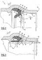
Figure 2 est une vue en coupe longitudinale d'une partie de la jonction tubulaire de laFigure 1 avant insertion du bout uni, la garniture d'étanchéité étant disposée dans le bout à emboîtement et le bout uni étant omis; - les
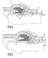
Figures 3 à 5 sont des vues correspondantes à celle de laFigure 2 , la jonction tubulaire étant à l'état monté dans le cas de différents jeux formés entre le bout uni et le bout à emboîtement ; - la
Figure 6 est une vue analogue à celle de laFigure 5 , le bout uni étant angulairement décalé du bout à emboîtement ; - la
Figure 7 est une vue analogue à celle de laFigure 3 montrant un deuxième mode de réalisation de la jonction tubulaire selon l'invention et comportant une dent d'accrochage auxiliaire ; - la
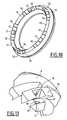
Figure 8 est une vue en perspective d'une garniture d'étanchéité munie d'éléments de verrouillage et d'éléments anti-extrusion d'une jonction tubulaire selon un troisième mode de réalisation de l'invention ; - la
Figure 9 est une vue à l'état non assemblé d'une partie de la garniture d'étanchéité de laFigure 8 ; - la
Figure 10 est une vue en perspective d'une garniture d'étanchéité d'une jonction tubulaire selon un quatrième mode de réalisation de l'invention ; - la
Figure 11 est une vue en perspective d'une partie de la garniture d'étanchéité de laFigure 10 , à l'état non assemblé ; - la
Figure 12 est une vue en perspective à l'état non assemblé d'une partie d'une garniture d'étanchéité d'une jonction tubulaire selon un cinquième mode réalisation de l'invention ; - la
Figure 13 est une vue en perspective à l'état non assemblé d'une partie d'une garniture d'étanchéité d'une jonction tubulaire selon un sixième mode de réalisation de l'invention ; - la
Figure 14 est une vue en coupe transversale de la garniture d'étanchéité de laFigure 13 à l'état assemblé ; - la
Figure 15 est une vue en perspective d'une garniture d'étanchéité d'une jonction tubulaire selon un septième mode de réalisation de l'invention ; et - la
Figure 16 est une vue en perspective d'une partie de la garniture d'étanchéité de laFigure 15 , à l'état non assemblé.
- the
Figure 1 is a perspective view of a tubular junction according to the invention in the unassembled state; - the
Figure 2 is a longitudinal sectional view of a portion of the tubular junction of theFigure 1 before insertion of the spigot, the packer being disposed in the interlocking end and the spigot being omitted; - the
Figures 3 to 5 are views corresponding to that of theFigure 2 , the tubular junction being in the mounted state in the case of different sets formed between the spigot end and the interlocking end; - the
Figure 6 is a view similar to that of theFigure 5 , the spigot being angularly offset from the interlocking end; - the
Figure 7 is a view similar to that of theFigure 3 showing a second embodiment of the tubular junction according to the invention and having an auxiliary attachment tooth; - the
Figure 8 is a perspective view of a packer provided with locking elements and anti-extrusion elements of a tubular junction according to a third embodiment of the invention; - the
Figure 9 is a view in the unassembled state of a portion of the seal of theFigure 8 ; - the
Figure 10 is a perspective view of a seal of a tubular junction according to a fourth embodiment of the invention; - the
Figure 11 is a perspective view of a portion of the seal of theFigure 10 , in the unassembled state; - the
Figure 12 is a perspective view in the unassembled state of a portion of a seal of a tubular junction according to a fifth embodiment of the invention; - the
Figure 13 is a perspective view in the unassembled state of a portion of a seal of a tubular joint according to a sixth embodiment of the invention; - the
Figure 14 is a cross-sectional view of the seal of theFigure 13 in the assembled state; - the
Figure 15 is a perspective view of a seal of a tubular junction according to a seventh embodiment of the invention; and - the
Figure 16 is a perspective view of a portion of the seal of theFigure 15 , in the unassembled state.
La
La jonction tubulaire 2 comporte un premier élément de canalisation muni d'un bout à emboîtement 4, un second élément de canalisation muni d'un bout uni 6, une garniture d'étanchéité 8, des éléments anti-extrusion 10 et des éléments de verrouillage 12.The
La jonction tubulaire 2 définit un axe central X-X. Dans ce qui suit les expressions « axialement », « radialement » et « circonférentiellement » seront utilisées par rapport à cet axe central X-X.The
Le bout à emboîtement 4 et le bout uni 6 sont fabriqués par exemple en fonte. De plus, ces éléments de canalisation peuvent être revêtus d'une couche protectrice non représentée.The interlocking
Le bout à emboîtement 4 comporte une bride de fixation 14 pour l'assemblage avec un élément de canalisation (non représenté) muni d'une bride correspondante, ainsi qu'une extrémité libre 16, tournée vers le bout uni 6 à l'état non assemblé. Le bout à emboîtement 4 comporte en outre une gorge annulaire intérieure 18 (voir
Comme ceci est visible sur la
Le bout à emboîtement 4 comporte une surface radialement intérieure 21 qui s'étend entre l'extrémité libre 16 et la paroi de gorge 20. Cette surface 21 est sensiblement cylindrique et est définie par un rayonR autour de l'axe X-X. Le bout uni 6 comporte une surface radialement extérieure 22 cylindrique et définie par un rayonr autour de l'axe X-X. Lors de la fabrication du bout à emboîtement 4 et du bout uni 6, les rayonsR etr sont compris dans une gamme de tolérances de fabrication. En conséquence, la surface intérieure 21 et la surface extérieure 22 délimitent entre elles un jeu J =R-r. En fonction des tolérances de fabrication, ce jeu J est situé entre un jeu maximal Jmax(voir
Le plus couramment cependant, le jeu entre le bout uni et le bout à emboîtement est un jeu moyen Jmoy(voir
La garniture d'étanchéité 8 est par exemple fabriquée en caoutchouc. Elle comporte un corps de base 24 et une lèvre d'étanchéité 26.The
Chaque élément de verrouillage 12 est un élément fabriqué en une matière ayant une dureté supérieure à celle de la surface du bout uni 6, telle que du metal. L'élément de verrouillage 12 a une section génératrice montrée sur laEach locking
En se référant à la
L'élément de verrouillage 12 comporte au niveau de la jonction entre la face intérieure 30 et la face de liaison 32 une dent d'accrochage principale 36 adaptée pour venir mordre dans la surface extérieure 22 du bout uni. Cette dent comporte une surface d'accrochage principale 37 dirigée à l'opposé de l'extrémité libre 16 et formant un angle γ avec la face intérieure 30 de l'élément de verrouillage.The locking
Enfin, l'élément de verrouillage 12 est muni d'une butée 38 adaptée pour limiter la pénétration de la dent d'accrochage principale 36 dans le bout uni 6. La butée 38 s'étend axialement à l'opposé de l'extrémité libre du bout à emboîtement et fait saillie de la face de liaison 32.Finally, the locking
L'élément de verrouillage 12 est fixé à la garniture 8. A cet effet, l'élément de verrouillage 12 porte un ou plusieurs tétons d'ancrage 40 qui font saillie sur la face de liaison 32. Chaque téton 40 est fixé à la garniture d'étanchéité 8 par surmoulage.The locking
Afin de garantir une mobilité relative de l'élément de verrouillage 12 celui-ci est fixé uniquement par le téton d'ancrage 40 à la garniture d'étanchéité 8. La zone de contact entre la surface de liaison 32 et de la garniture d'étanchéité étant dépourvue de tout autre liant.In order to ensure relative mobility of the locking
Comme ceci est visible sur la
Les éléments anti-extrusion 10 sont de préférence réalisés en une matière plastique, telle du polyamide, du polyéthylène ou du polypropylène.The
Les éléments anti-extrusion 10 sont fixés à la garniture d'étanchéité 8 par tout moyen approprié. Ils peuvent notamment être fixés par collage, surmoulage, encliquetage, vissage ou rivetage.The
Le montage de la jonction tubulaire selon l'invention s'effectue de la manière suivante.The assembly of the tubular junction according to the invention is carried out as follows.
Tout d'abord, les éléments anti-extrusion 10 et les éléments de verrouillage 12 sont fixés sur la garniture d'étanchéité 8. Ainsi, la garniture d'étanchéité 8, les éléments de verrouillage 12 et les éléments anti-extrusion 10 peuvent être manipulés d'un seul bloc. Ensuite, la garniture d'étanchéité 8, équipée des éléments de verrouillage 12 et des éléments anti-extrusion 10 est disposée à la main dans la gorge intérieure 18. La jonction prend alors la configuration montrée sur la
Lors de l'insertion du bout uni 6 dans le bout à emboîtement 4, l'élément de verrouillage 12 bascule dans le sens horaire sur la
Le fonctionnement des éléments de verrouillage 12, lors de la mise en pression du joint, diffère en fonction du jeu radial J subsistant entre la surface intérieure 21 et la surface extérieure 22.The operation of the locking
Dans le cas où le jeu J est situé dans une première gamme de jeux dans laquelle les jeux sont élevés et peuvent atteindre le jeu Jmax de la
Lors du recul du bout uni 6 sous l'effet d'une pression intérieure élevée, l'élément de verrouillage 12 pivote d'abord dans le sens anti-horaire autour de la dent d'accrochage principale 36 qui est en appui sur la surface extérieure 22 du bout uni 6 et qui forme alors un point de basculement, et ce jusqu'à ce que sa face d'application 28 vienne en appui contre la paroi de gorge 20. L'élément de verrouillage 12 se déplace alors axialement vers l'extrémité libre 16 du bout à emboîtement 4 et radialement vers l'intérieur par glissement de la face d'application 28 sur la paroi de gorge 20, provoquant ainsi la pénétration progressive de la dent d'accrochage 36 de l'élément de verrouillage 12 dans la surface extérieure 22 du bout uni 6 et ce jusqu'à obtenir un verrouillage par effet de coin. On aboutit ainsi à une configuration de verrouillage telle que par exemple celle représentée sur la
Avantageusement, la butée 38 en saillie axiale vers l'intérieur du bout à emboîtement 4 limite la pénétration de la dent d'accrochage 36 dans le bout uni 6 afin d'empêcher toute pénétration excessive susceptible de détériorer le bout uni.Advantageously, the
Dans le cas où le jeu J est situé dans une deuxième gamme de jeux moindres correspondant à des jeux inférieurs aux jeux de la première gamme de jeux, et englobant notamment le jeu Jmin (voir
Lors du recul du bout uni 6 sous l'effet de la pression intérieure, l'élément de verrouillage 12 pivote tout d'abord dans le sens anti-horaire autour de la dent d'accrochage principale 36 qui est en appui sur la surface extérieure 22 du bout uni 6 et qui forme alors un point de basculement, et ce jusqu'à ce que le point de basculement 34 vienne en appui contre la paroi de gorge 20 du bout à emboîtement 4. A ce moment là, l'élément de verrouillage 12 pivote dans le sens anti-horaire autour du point de basculement 34, provoquant alors la pénétration progressive de la dent d'accrochage principale 36 dans la surface extérieure 22 du bout uni 6 et ce jusqu'à ce que l'élément de verrouillage 12 s'arc-boute entre le bout uni 6 et le bout à emboîtement 4 par l'intermédiaire respectivement de la dent d'accrochage 36 et du point de basculement 34, obtenant ainsi un verrouillage par arc-boutement.During the recoil of the
Dans la configuration de verrouillage à jeu Jmin représentée sur la
Dans l'exemple de réalisation décrit, l'angle entre les faces 32 et 28 formant le point de basculement 34 est un angle aigu qui favorise l'ancrage du point de basculement 34 dans la gorge 18 du bout à emboîtement 4 en vue de former un centre de rotation stable.In the embodiment described, the angle between the
Sur la
Sur la
De manière avantageuse, la face radialement intérieure 30 de l'insert de verrouillage 12 est munie d'une dent d'accrochage 50 auxiliaire. Cette dent auxiliaire 50 est disposée à l'opposé de la dent d'accrochage principale 36, c'est-à-dire du côté de l'extrémité libre 16 du bout à emboîtement 4. Cette dent d'accrochage auxiliaire 50 est adaptée pour garantir le verrouillage lorsque le jeu J est faible, c'est à dire proche du jeu minimum Jmin, en s'opposant alors au glissement de la dent d'accrochage principale 36 sur la surface extérieure 22 du bout uni 6, ce risque de glissement étant potentiellement élevé à jeu faible compte-tenu du faible angle d'inclinaison, par rapport à la surface extérieure 22, de la réaction d'appui au niveau de cette dent d'accrochage 36. La dent d'accrochage auxiliaire 50 comporte une surface d'accrochage auxiliaire 52 qui forme un angle auxiliaire δ avec la face intérieure 30 de l'élément de verrouillage. Cet angle auxiliaire δ est supérieur à l'angle γ.Advantageously, the radially
Selon un troisième mode de réalisation, décrit en référence aux
En ce qui concerne la fixation, les éléments de verrouillage 12 et les éléments anti-extrusion 10 sont équipés de tétons d'ancrage 40 solidaires de la face de liaison 32, ces tétons 40 étant surmoulés dans l'élastomère de la garniture 8. Avantageusement, les tétons d'ancrage 40 sont au préalable recouverts d'un agent d'adhésion permettant aux tétons 40 d'adhérer à l'élastomère après injection de celui-ci dans le moule. Ainsi, il n'est plus possible de démonter les éléments de verrouillage 12 et les éléments anti-extrusion 10 après moulage de la garniture 8. On notera cependant que les éléments de verrouillage 12 conservent avantageusement une certaine souplesse ou mobilité par rapport à la garniture d'étanchéité, dans la mesure où seuls les tétons d'ancrage 40 sont liés à l'élastomère. La face de liaison 32 est à cet effet disposée librement sur la garniture d'étanchéité 8.As regards the fixing, the locking
Dans le quatrième mode de réalisation, décrit en se référant aux
De plus, les éléments de verrouillage 12 étant rapportés sur les éléments anti-extrusion 10 de la deuxième série, il n'est pas nécessaire qu'ils épousent les profils du bout uni 6 et du bout à emboîtement, contrairement au modes de réalisation précédemment décrits où les éléments de verrouillage 12 sont incurvés en arc de cercle. Les éléments de verrouillage 12 ont donc ici des profils intérieurs et extérieurs rectilignes et notamment une dent d'accrochage principale 36 rectiligne. Ceci est avantageux car un même élément de verrouillage 12 peut alors être utilisé dans une plage de tolérances diamétrales sur les tuyaux qui est supérieure à la plage de tolérances diamétrales autorisée par l'élément de verrouillage 12 incurvé des
Le cinquième mode de réalisation (voir
Le sixième mode de réalisation montré sur les
Sur les
L'élément de verrouillage 12 constitue un segment en forme d'arc de cercle dont le bord radialement intérieur constitue une denture d'accrochage munie d'une pluralité de dents d'accrochage principales 36 décalées circonférentiellement et séparées les unes des autres par des gorges d'espacement 60. Dans ce cas, la surface radialement intérieure formée par chaque gorge d'espacement 60 entre les dents 36 permet de limiter la pénétration des dents 36 dans le bout uni 6 et remplace ainsi avantageusement la butée 38 décrite en référence au premier mode de réalisation.The locking
En variante, la denture circonférentielle peut être remplacée par une dent 36 continue, comme pour les éléments de verrouillage 12 précédemment décrits.Alternatively, the circumferential toothing may be replaced by a
L'élément de verrouillage 12 est pris en sandwich entre l'élément anti-extrusion 10 et la garniture 8. Les deux éléments 10 et 12 assemblés ont en section une forme générale triangulaire sensiblement identique à celle des éléments de verrouillage 12 précédents. Ainsi, la face d'application 28 de l'élément de verrouillage 12 est prolongée par une face d'application supplémentaire 28A solidaire de l'élément anti-extrusion 10.The locking
On notera cependant que l'élément de verrouillage 12 présente ici une épaisseur axiale réduite, permettant ainsi de réduire significativement le coût des éléments de verrouillage 12 en comparaison du coût des éléments de verrouillage 12 décrits en référence aux
Enfin, si ce mode de réalisation des
Il est à noter que les différentes caractéristiques décrites en liaison avec un mode de réalisation spécifique peuvent être appliquées d'une manière analogue aux autres modes de réalisation.It should be noted that the various features described in connection with a specific embodiment can be applied in a manner analogous to the other embodiments.
On notera enfin que le montage de la garniture d'étanchéité et de verrouillage composite selon l'invention dans la gorge intérieure 18 du bout à emboîtement 4, préalablement à l'insertion du bout uni 6, s'effectue à la main, en déformant simplement la garniture 8 en cardioïde de manière à pouvoir l'introduire aisément dans l'extrémité libre 16 rétrécie du bout à emboîtement 4.Finally, it will be noted that the assembly of the composite seal and lock according to the invention in the
Claims (22)
- Tubular joint of the type comprising- a bell end (4) of a first pipe element, the bell end (4) extending along a central axis (X-X), being equipped with an internal groove (18) and a free extremity (16) in which is inserted a spigot end (6) of a second pipe element, the internal grove (18) forming a truncated cone-shaped groove wall (20) which forms a first angle (α) with the central axis and is inclined to the central axis (X-X) while narrowing toward the free extremity (16) of the bell end (4),- a seal (8) disposed in the internal groove (18),- at least one locking element (12) adapted to lock the spigot end (6) relative to the bell end (4),- the spigot end (6) and the bell end (4) defining a radial clearance (J) between themselves, this clearance being able to be situated either in a first range of clearances or in a second range of clearances, the clearances of the second range of clearances being smaller than the clearances of the first range of clearances,characterised in that the locking element (12) comprises at least one main fixing tooth (36) adapted to bite into an external surface (22) of the spigot end (6) and a contact face (28) which, when the seal is unstressed, is inclined at a second angle (β) relative to the central axis (X-X), this second angle (β) being substantially identical to the first angle of inclination, and which is adapted to be applied to the groove wall (20) and to achieve locking by a wedge effect during pressurisation and when the clearance (J) lies in the first range of clearances, and
in that, during pressurisation and when the clearance lies in the second range of clearances, the locking element (12) is adapted to form a rocking point (34) of this element (12) around the groove wall (20), and the main fixing tooth (36) is adapted to bite into the external surface (22) by the arch-buttress effect of the locking element (12) between the spigot end (6) and the bell end (4). - Tubular joint according to claim 1,characterised in that, when the clearance (J) is in the first range of clearances, the contact face (28) is adapted to be applied in a planar manner and to slide on the groove wall (20) when the spigot end (6) is retracted from the bell end (4) in the direction tending to remove the spigot end from the bell end (4), the locking element (12) moving axially toward the free extremity (16) and radially toward the interior by sliding of the contact face (28) on the groove wall.
- Tubular joint according to either claim 1 or claim 2,characterised in that, when the contact face (28) of the locking element (12) is applied to the groove wall (20), the main fixing tooth (36) extends substantially radially toward the interior relative to the central axis (X-X).
- Tubular joint according to any one of claims 1 to 3,characterised in that the locking element (12) comprises an internal face (30) which, when the radial clearance is a minimal clearance (Jmin), extends substantially parallel to the central axis (X-X), the minimal clearance constituting a lower limit of the second range of clearances.
- Tubular joint according to any one of claims 1 to 4,characterised in that the locking element (12) comprises a stop (38) adapted to limit the penetration of the main fixing tooth (36) in the spigot end (6).
- Tubular joint according to claim 5,characterised in that the stop (38) extends axially away from the free extremity (16) of the bell end (4).
- Tubular joint according to any one of claims 1 to 6,characterised in that the locking element (12) comprises an auxiliary fixing tooth (50) which is axially offset from the main fixing tooth (36) in the direction toward the free extremity (16) of the bell end (4) andin that the auxiliary fixing tooth (50) is adapted to fix on to the external surface (22) of the spigot end (6) when the clearance (J) is close to the minimal clearance (Jmin).
- Tubular joint according to claim 7,characterised in that the auxiliary fixing tooth (50) comprises an auxiliary fixing surface (52) which is directed away from the free extremity (16) of the bell end (4) and which forms an angle (δ) with the internal face (30) of the locking element (12).
- Tubular joint according to any one of the preceding claims,characterised in that the main fixing tooth (36) has a non-rectilinear shape, in particular is shaped as an arc of a circle.
- Tubular joint according to any one of claims 1 to 8,characterised in that the main fixing tooth (36) has a rectilinear shape.
- Tubular joint according to any one of the preceding claims,characterised in that it comprises at least one anti-extrusion element (10) which is adapted to prevent the extrusion of the seal (8) between the spigot end (6) and the bell end (4).
- Tubular joint according to claim 11,characterised in that the anti-extrusion element (10) is made of plastics material having a resistance to deformation which is greater than that of the material of the seal (8), in particular of polyamide, polyethylene or polypropylene.
- Tubular joint according to either claim 11 or claim 12characterised in that the anti-extrusion element (10) is fixed to the seal (8).
- Tubular joint according to any one of claims 11 to 13,characterised in that the anti-extrusion element (10) is disposed circumferentially between two locking elements (12).
- Tubular joint according to any one of claims 11 to 13,characterised in that the anti-extrusion element (10) carries one of the locking elements (12).
- Tubular joint according to claim 15,characterised in that the locking element (12) delimits a gap (E) from the anti-extrusion element (10) supporting it, this gap (E) imparting mobility to the locking element relative to the seal (8).
- Tubular joint according to any one of the preceding claims,characterised in that the locking element (12) is produced from a material of which the hardness is greater than that of the material of the spigot end (6), in particular from metal.
- Tubular joint according to any one of the preceding claims,characterised in that it comprises at least one circumferential spacer (56) which is made of resilient material, in particular is integral with the seal, the spacer (56) being disposed between a locking element (12) and another adjacent locking element or an adjacent anti-extrusion element (10).
- Tubular joint according to any one of the preceding claims,characterised in that the locking element (12) is fixed to the seal (8) or to an anti-extrusion element (10) by means of at least one fastening member (40), in particular a screw or an anchor stud.
- Tubular joint according to any one of the preceding claims,characterised in that the locking element (12) has a substantially triangular cross-section.
- Tubular joint according to any one of the preceding claims,characterised in that the locking element (12) forms a connecting face (32) adjacent to the seal (8).
- Tubular joint according to any one of the preceding claims,characterised in that the first angle (α) is between 10° and 55°.
Applications Claiming Priority (2)
| Application Number | Priority Date | Filing Date | Title |
|---|---|---|---|
| FR0654661AFR2907877B1 (en) | 2006-10-31 | 2006-10-31 | TUBULAR JUNCTION |
| PCT/FR2007/001779WO2008053100A2 (en) | 2006-10-31 | 2007-10-26 | Tubular connection |
Publications (2)
| Publication Number | Publication Date |
|---|---|
| EP2084446A2 EP2084446A2 (en) | 2009-08-05 |
| EP2084446B1true EP2084446B1 (en) | 2013-04-10 |
Family
ID=38288540
Family Applications (1)
| Application Number | Title | Priority Date | Filing Date |
|---|---|---|---|
| EP07866452.1AActiveEP2084446B1 (en) | 2006-10-31 | 2007-10-26 | Tubular connection |
Country Status (10)
| Country | Link |
|---|---|
| US (1) | US8096585B2 (en) |
| EP (1) | EP2084446B1 (en) |
| JP (1) | JP5113181B2 (en) |
| CN (1) | CN101730812B (en) |
| AU (1) | AU2007316051B2 (en) |
| BR (1) | BRPI0716364B1 (en) |
| ES (1) | ES2417134T3 (en) |
| FR (1) | FR2907877B1 (en) |
| RU (1) | RU2432518C2 (en) |
| WO (1) | WO2008053100A2 (en) |
Cited By (1)
| Publication number | Priority date | Publication date | Assignee | Title |
|---|---|---|---|---|
| FR3156181A1 (en)* | 2023-12-05 | 2025-06-06 | Saint-Gobain Pam Canalisation | Tubular joint comprising a sealing gasket with locking inserts fixed by form-fitting |
Families Citing this family (35)
| Publication number | Priority date | Publication date | Assignee | Title |
|---|---|---|---|---|
| US7774915B2 (en)* | 2007-05-16 | 2010-08-17 | S & B Technical Products, Inc. | Ductile iron pressure fit gasket |
| EP2392845B1 (en) | 2009-01-27 | 2018-05-30 | Kubota Corporation | Pipe joint |
| EP2486319A4 (en)* | 2009-10-09 | 2018-02-21 | Mueller International, LLC | Simplified low insertion force sealing device capable of self restraint and joint deflection |
| US8857861B2 (en) | 2009-10-12 | 2014-10-14 | Mueller International, Llc | Self-restrained pipe joint system |
| CA2799588A1 (en)* | 2010-05-24 | 2011-12-01 | Mueller International Llc | Simplified low insertion force sealing device capable of self restraint and joint deflection |
| US8544851B2 (en) | 2010-08-24 | 2013-10-01 | Mueller International, Llc | Gasket for parabolic ramp self restraining bell joint |
| CA2806120A1 (en) | 2010-08-24 | 2012-03-01 | Mueller International, Llc | Gasket for parabolic ramp self restraining bell joint |
| US9045961B2 (en)* | 2011-01-31 | 2015-06-02 | National Oilwell Varco, L.P. | Blowout preventer seal and method of using same |
| WO2013155191A2 (en) | 2012-04-10 | 2013-10-17 | National Oilwell Varco, L.P. | Blowout preventer seal assembly and method of using same |
| EP2664833B1 (en)* | 2012-05-14 | 2016-04-27 | Trelleborg Pipe Seals Lelystad BV | Restraint Seal |
| FR2998350B1 (en)* | 2012-11-22 | 2015-09-04 | Saint Gobain Pont A Mousson | ENCLOSED END FOR TUBULAR JUNCTION AND CORRESPONDING TUBULAR JUNCTION |
| FR2998349B1 (en)* | 2012-11-22 | 2015-05-29 | Saint Gobain Pont A Mousson | SEALING ASSEMBLY FOR TUBULAR JUNCTION AND CORRESPONDING TUBULAR JUNCTION |
| GB201300114D0 (en)* | 2013-01-04 | 2013-02-20 | Connext Ltd | Pipe fitting |
| US10801622B2 (en)* | 2013-04-18 | 2020-10-13 | Bal Seal Engineering, Llc | Interlocking face seal assemblies and related methods |
| USD741163S1 (en)* | 2014-03-14 | 2015-10-20 | Bmt Co., Ltd. | Check ring for indicating nut tightening amount |
| US9829137B2 (en) | 2014-03-20 | 2017-11-28 | Griffin Pipe Products Co., Llc | Flexible pipe joint |
| CN105465362B (en)* | 2014-09-09 | 2019-05-24 | 圣戈班管道系统有限公司 | Anticreep sealing ring, anti-drop block and the conduit assembly including the sealing ring |
| US20170328473A1 (en)* | 2014-12-09 | 2017-11-16 | Hi-Sten, Co., Ltd. | Packing member for water-tightening pipe |
| US9951869B2 (en) | 2015-02-04 | 2018-04-24 | Trelleborg Pipe Seals Lelystad BV | Seal for belled pipe |
| US10107434B1 (en)* | 2015-10-02 | 2018-10-23 | Mcwane, Inc. | High deflection Restrained pipe joint |
| USD857859S1 (en)* | 2017-07-12 | 2019-08-27 | Mcwane, Inc. | Restrained gasket |
| USD846095S1 (en)* | 2017-07-12 | 2019-04-16 | Mcwane, Inc. | Restrained gasket |
| US10288199B2 (en)* | 2016-05-11 | 2019-05-14 | Mcwane, Inc. | Restrained plastic pipe joint and method of making same |
| CA3045453A1 (en) | 2016-12-02 | 2018-06-07 | Total Piping Solutions, Inc. | Encapsulation sleeve gasket assembly with removable inner layer |
| US11287076B2 (en)* | 2016-12-02 | 2022-03-29 | Total Piping Solutions, Inc. | Encapsulation sleeve gasket assembly with detachable inner layer |
| US11506312B2 (en)* | 2016-12-02 | 2022-11-22 | Total Piping Solutions, Inc. | Encapsulation sleeve gasket assembly with detachable inner layer |
| US10808844B2 (en)* | 2017-02-06 | 2020-10-20 | North American Pipe Corporation | System, method and apparatus for pipe restrained joint seal and lock |
| US10876672B2 (en)* | 2017-02-24 | 2020-12-29 | S & B Technical Products, Inc. | Sealing joint for low pressure pipe systems and method of manufacture |
| CA3036588C (en)* | 2017-08-22 | 2023-01-03 | Mcwane, Inc. | Restrained gasket for plastic pipes |
| USD846098S1 (en)* | 2017-09-19 | 2019-04-16 | Mcwane, Inc. | Restrained gasket |
| USD846096S1 (en)* | 2017-09-19 | 2019-04-16 | Mcwane, Inc. | Restrained gasket |
| US11365839B2 (en)* | 2018-04-30 | 2022-06-21 | S & B Technical Products, Inc. | Sealing and restraining gasket for use in plastic pipelines |
| KR102181761B1 (en)* | 2018-12-14 | 2020-11-24 | 이종태 | Sealing member for securing of a pipe and pipe connector having it |
| US11204114B2 (en) | 2019-11-22 | 2021-12-21 | Trinity Bay Equipment Holdings, LLC | Reusable pipe fitting systems and methods |
| CN111071800A (en)* | 2019-12-06 | 2020-04-28 | 刘月金 | Full-automatic inferior-quality sanitary towel linking pipe conveying and separating powder machine |
Family Cites Families (33)
| Publication number | Priority date | Publication date | Assignee | Title |
|---|---|---|---|---|
| US4693483A (en)* | 1984-07-13 | 1987-09-15 | Vassallo Research & Development Corporation | Composite gasket and fitting including same |
| US4637618A (en)* | 1984-07-13 | 1987-01-20 | Vassallo Research & Development Corporation | Composite gasket and fitting including same |
| US4826028A (en)* | 1985-03-18 | 1989-05-02 | Vassallo Research & Development Corp. | Gasket seating ring |
| US4834398A (en)* | 1987-08-31 | 1989-05-30 | S & B Technical Products, Inc. | Pipe gasket |
| FR2621376B1 (en)* | 1987-10-01 | 1989-12-22 | Pont A Mousson | SEALING FOR TELESCOPIC LOCKED GASKETS |
| JPH0187392U (en)* | 1987-11-30 | 1989-06-09 | ||
| SE8800348L (en)* | 1988-02-03 | 1989-08-04 | Forsheda Ab | SEALING RING AND TOOLS FOR PRODUCING THEREOF |
| FR2655705B1 (en)* | 1989-12-11 | 1992-05-29 | Pont A Mousson | COMPOSITE SEALING FOR LOCKED ASSEMBLY OF MALE-TIP PIPES AND INTERLOCKING. |
| US5267248A (en) | 1990-12-24 | 1993-11-30 | Eastman Kodak Company | Method and apparatus for selecting an optimum error correction routine |
| FR2679622B1 (en)* | 1991-07-26 | 1994-09-30 | Pont A Mousson | COMPOSITE SEALING FOR LOCKED PIPE ASSEMBLY AND CORRESPONDING LOCKED ASSEMBLY. |
| FR2686140B1 (en)* | 1992-01-13 | 1995-05-24 | Pont A Mousson | GASKET JOINT BETWEEN PIPES AND SEALING FOR SUCH A JOINT. |
| US5464228A (en)* | 1992-11-04 | 1995-11-07 | United States Pipe And Foundry Company | Restraining element for pressure pipe joints |
| DE4300037C1 (en)* | 1993-01-02 | 1994-04-21 | Raymond A & Cie | Releasable socket coupling device for pipe - has formed retaining edges onto rib with deformable guides for plug insertion |
| EP0670020B1 (en)* | 1993-09-16 | 1999-07-14 | United States Pipe And Foundry Company, Inc. | Improved restraining element for pressure pipe joints |
| AU694988B2 (en)* | 1995-02-21 | 1998-08-06 | Iplex Pipelines Australia Pty Limited | Pipe seal |
| FR2765658B1 (en)* | 1997-07-07 | 1999-08-20 | Pont A Mousson | LOCKING DEVICE FOR ASSEMBLY OF TWO PIPE ELEMENTS, AND ASSEMBLY OF PIPE ELEMENTS INCLUDING APPLICATION |
| JP2002295751A (en)* | 2001-03-29 | 2002-10-09 | Riken Corp | Plug-in fittings |
| AT409945B (en)* | 2001-08-02 | 2002-12-27 | Schnallinger Helmuth | Thermoplastic pipe end with a sealing ring, is produced by placing the ring in a preformed inner wall groove and then shaping the groove to hold the seal in place |
| NO314517B1 (en)* | 2001-08-21 | 2003-03-31 | Raufoss Asa | Support sleeve for use in pipe connection and coupling housing for pipe connection, for mounting such a support sleeve |
| FR2830070B1 (en)* | 2001-09-26 | 2006-11-03 | Saint Gobain Pont A Mousson | JOINT FOR CONNECTING TWO TUBULAR ELEMENTS AND ITS ASSEMBLY METHOD |
| US6688652B2 (en)* | 2001-12-12 | 2004-02-10 | U.S. Pipe And Foundry Company | Locking device and method for securing telescoped pipe |
| US7140618B2 (en)* | 2003-01-16 | 2006-11-28 | Vassallo Research & Development Corporation | Socket with dual-functional composite gasket |
| AU2003282837B2 (en)* | 2003-10-15 | 2010-03-04 | United States Pipe And Foundry Company, Llc | Energized restraining gasket for mechanical joints of pipes |
| US7158034B2 (en)* | 2004-01-12 | 2007-01-02 | Corbett Jr Bradford G | Pipe gasket manufacturing and identification method with RFID tracking |
| US7207606B2 (en)* | 2004-04-19 | 2007-04-24 | United States Pipe And Foundry Company, Llc | Mechanical pipe joint, gasket, and method for restraining pipe spigots in mechanical pipe joint bell sockets |
| FR2875888B1 (en) | 2004-09-24 | 2006-12-01 | Saint Gobain Pam Sa | SEAL TRIM AND CORRESPONDING ASSEMBLY |
| DE102004062887B3 (en)* | 2004-12-27 | 2005-10-13 | A. Raymond & Cie | Coupling has locking protrusion which in extended position of plug-in component when it is not properly fitted in housing component prevents movement of locking component into inserted position |
| US8235427B2 (en)* | 2005-06-10 | 2012-08-07 | S & B Technical Products, Inc. | Self restrained ductile iron fitting |
| US7815225B2 (en)* | 2005-06-10 | 2010-10-19 | S & B Technical Products, Inc. | Self restrained ductile iron fitting |
| DE102006019257B4 (en)* | 2006-04-26 | 2010-08-05 | A. Raymond Et Cie | Fluid line coupling |
| USD559363S1 (en)* | 2006-05-30 | 2008-01-08 | S & B Technical Products, Inc. | Pipe gasket |
| USD557386S1 (en)* | 2006-05-30 | 2007-12-11 | S & B Technical Products, Inc. | Pipe gasket |
| US7774915B2 (en)* | 2007-05-16 | 2010-08-17 | S & B Technical Products, Inc. | Ductile iron pressure fit gasket |
- 2006
- 2006-10-31FRFR0654661Apatent/FR2907877B1/ennot_activeExpired - Fee Related
- 2007
- 2007-10-26ESES07866452Tpatent/ES2417134T3/enactiveActive
- 2007-10-26CNCN200780046517.2Apatent/CN101730812B/enactiveActive
- 2007-10-26JPJP2009533904Apatent/JP5113181B2/ennot_activeExpired - Fee Related
- 2007-10-26RURU2009120609/06Apatent/RU2432518C2/enactive
- 2007-10-26WOPCT/FR2007/001779patent/WO2008053100A2/enactiveApplication Filing
- 2007-10-26USUS12/447,515patent/US8096585B2/ennot_activeExpired - Fee Related
- 2007-10-26EPEP07866452.1Apatent/EP2084446B1/enactiveActive
- 2007-10-26BRBRPI0716364-9Apatent/BRPI0716364B1/ennot_activeIP Right Cessation
- 2007-10-26AUAU2007316051Apatent/AU2007316051B2/ennot_activeCeased
Cited By (2)
| Publication number | Priority date | Publication date | Assignee | Title |
|---|---|---|---|---|
| FR3156181A1 (en)* | 2023-12-05 | 2025-06-06 | Saint-Gobain Pam Canalisation | Tubular joint comprising a sealing gasket with locking inserts fixed by form-fitting |
| WO2025119957A1 (en)* | 2023-12-05 | 2025-06-12 | Saint-Gobain Pam Canalisation | Tubular junction comprising a seal with locking inserts which are fastened as a result of complementing shapes |
Also Published As
| Publication number | Publication date |
|---|---|
| BRPI0716364A2 (en) | 2013-09-24 |
| EP2084446A2 (en) | 2009-08-05 |
| CN101730812B (en) | 2013-01-09 |
| AU2007316051A1 (en) | 2008-05-08 |
| WO2008053100A2 (en) | 2008-05-08 |
| RU2432518C2 (en) | 2011-10-27 |
| US8096585B2 (en) | 2012-01-17 |
| BRPI0716364A8 (en) | 2018-05-22 |
| WO2008053100A3 (en) | 2008-07-17 |
| US20100090460A1 (en) | 2010-04-15 |
| CN101730812A (en) | 2010-06-09 |
| ES2417134T3 (en) | 2013-08-06 |
| BRPI0716364B1 (en) | 2018-06-12 |
| AU2007316051B2 (en) | 2013-10-17 |
| JP2010508472A (en) | 2010-03-18 |
| RU2009120609A (en) | 2010-12-10 |
| FR2907877B1 (en) | 2012-06-22 |
| JP5113181B2 (en) | 2013-01-09 |
| FR2907877A1 (en) | 2008-05-02 |
Similar Documents
| Publication | Publication Date | Title |
|---|---|---|
| EP2084446B1 (en) | Tubular connection | |
| EP0541472B1 (en) | Locked joint for canalisations | |
| EP0893641B1 (en) | Device for connecting two pipe elements and use of such a pipe element connection device | |
| EP2633218B1 (en) | Assembly having sealing gasket with locking insert | |
| EP1319147A1 (en) | Coupling for connecting a tubular fitting to a pipe | |
| EP1792110B1 (en) | Gland seal and corresponding assembly | |
| EP0140171A1 (en) | Sealing ring for cast iron pipe couplings | |
| EP2359045B1 (en) | Seal assembly and corresponding tubular joint | |
| EP1977152B1 (en) | Tubular joint | |
| EP1860362B1 (en) | Pipe connector | |
| EP2923132B1 (en) | Sealing assembly for a tubular joint, and corresponding tubular joint | |
| FR2995651A1 (en) | Sealing assembly for tubular joint between spigot end and socket end for drain, has seal including heel, where heel is adapted to extend between external radial face and wall of groove, and heel is arranged with set of easing recesses | |
| EP4153894B1 (en) | Sealed and locked assembly | |
| EP1605195A1 (en) | Pipe coupling system and associated method of assembly | |
| FR2460439A1 (en) | Compression joint for smooth barrel synthetic resin pipes - has nut to wedge tapered sealing sleeve onto spigot barrel where V section grooves form shear key | |
| FR3084119A1 (en) | MEANS FOR ATTACHING A INSERTED PART AGAINST THE END OF A CYLINDRICAL PRIMINENCE IN A SONAR, CORRESPONDING SONAR | |
| FR2684163A1 (en) | SEALING RING DEVICE FORMING A JOINT FOR FLEXIBLE CONNECTION BETWEEN TWO ELEMENTS. |
Legal Events
| Date | Code | Title | Description |
|---|---|---|---|
| PUAI | Public reference made under article 153(3) epc to a published international application that has entered the european phase | Free format text:ORIGINAL CODE: 0009012 | |
| 17P | Request for examination filed | Effective date:20090430 | |
| AK | Designated contracting states | Kind code of ref document:A2 Designated state(s):AT BE BG CH CY CZ DE DK EE ES FI FR GB GR HU IE IS IT LI LT LU LV MC MT NL PL PT RO SE SI SK TR | |
| AX | Request for extension of the european patent | Extension state:BA HR RS | |
| 17Q | First examination report despatched | Effective date:20101129 | |
| RAX | Requested extension states of the european patent have changed | Extension state:RS Payment date:20090430 Extension state:HR Payment date:20090430 Extension state:BA Payment date:20090430 | |
| GRAP | Despatch of communication of intention to grant a patent | Free format text:ORIGINAL CODE: EPIDOSNIGR1 | |
| GRAS | Grant fee paid | Free format text:ORIGINAL CODE: EPIDOSNIGR3 | |
| GRAA | (expected) grant | Free format text:ORIGINAL CODE: 0009210 | |
| AK | Designated contracting states | Kind code of ref document:B1 Designated state(s):AT BE BG CH CY CZ DE DK EE ES FI FR GB GR HU IE IS IT LI LT LU LV MC MT NL PL PT RO SE SI SK TR | |
| AX | Request for extension of the european patent | Extension state:BA HR RS | |
| REG | Reference to a national code | Ref country code:GB Ref legal event code:FG4D Free format text:NOT ENGLISH | |
| REG | Reference to a national code | Ref country code:CH Ref legal event code:EP Ref country code:AT Ref legal event code:REF Ref document number:606210 Country of ref document:AT Kind code of ref document:T Effective date:20130415 | |
| REG | Reference to a national code | Ref country code:IE Ref legal event code:FG4D Free format text:LANGUAGE OF EP DOCUMENT: FRENCH | |
| REG | Reference to a national code | Ref country code:DE Ref legal event code:R096 Ref document number:602007029757 Country of ref document:DE Effective date:20130606 | |
| REG | Reference to a national code | Ref country code:ES Ref legal event code:FG2A Ref document number:2417134 Country of ref document:ES Kind code of ref document:T3 Effective date:20130806 | |
| PG25 | Lapsed in a contracting state [announced via postgrant information from national office to epo] | Ref country code:SI Free format text:LAPSE BECAUSE OF FAILURE TO SUBMIT A TRANSLATION OF THE DESCRIPTION OR TO PAY THE FEE WITHIN THE PRESCRIBED TIME-LIMIT Effective date:20130410 | |
| REG | Reference to a national code | Ref country code:NL Ref legal event code:VDEP Effective date:20130410 Ref country code:LT Ref legal event code:MG4D | |
| PG25 | Lapsed in a contracting state [announced via postgrant information from national office to epo] | Ref country code:GR Free format text:LAPSE BECAUSE OF FAILURE TO SUBMIT A TRANSLATION OF THE DESCRIPTION OR TO PAY THE FEE WITHIN THE PRESCRIBED TIME-LIMIT Effective date:20130711 Ref country code:FI Free format text:LAPSE BECAUSE OF FAILURE TO SUBMIT A TRANSLATION OF THE DESCRIPTION OR TO PAY THE FEE WITHIN THE PRESCRIBED TIME-LIMIT Effective date:20130410 Ref country code:NL Free format text:LAPSE BECAUSE OF FAILURE TO SUBMIT A TRANSLATION OF THE DESCRIPTION OR TO PAY THE FEE WITHIN THE PRESCRIBED TIME-LIMIT Effective date:20130410 Ref country code:SE Free format text:LAPSE BECAUSE OF FAILURE TO SUBMIT A TRANSLATION OF THE DESCRIPTION OR TO PAY THE FEE WITHIN THE PRESCRIBED TIME-LIMIT Effective date:20130410 Ref country code:LT Free format text:LAPSE BECAUSE OF FAILURE TO SUBMIT A TRANSLATION OF THE DESCRIPTION OR TO PAY THE FEE WITHIN THE PRESCRIBED TIME-LIMIT Effective date:20130410 Ref country code:IS Free format text:LAPSE BECAUSE OF FAILURE TO SUBMIT A TRANSLATION OF THE DESCRIPTION OR TO PAY THE FEE WITHIN THE PRESCRIBED TIME-LIMIT Effective date:20130810 Ref country code:PT Free format text:LAPSE BECAUSE OF FAILURE TO SUBMIT A TRANSLATION OF THE DESCRIPTION OR TO PAY THE FEE WITHIN THE PRESCRIBED TIME-LIMIT Effective date:20130812 | |
| PG25 | Lapsed in a contracting state [announced via postgrant information from national office to epo] | Ref country code:BG Free format text:LAPSE BECAUSE OF FAILURE TO SUBMIT A TRANSLATION OF THE DESCRIPTION OR TO PAY THE FEE WITHIN THE PRESCRIBED TIME-LIMIT Effective date:20130710 Ref country code:PL Free format text:LAPSE BECAUSE OF FAILURE TO SUBMIT A TRANSLATION OF THE DESCRIPTION OR TO PAY THE FEE WITHIN THE PRESCRIBED TIME-LIMIT Effective date:20130410 Ref country code:CY Free format text:LAPSE BECAUSE OF FAILURE TO SUBMIT A TRANSLATION OF THE DESCRIPTION OR TO PAY THE FEE WITHIN THE PRESCRIBED TIME-LIMIT Effective date:20130410 Ref country code:LV Free format text:LAPSE BECAUSE OF FAILURE TO SUBMIT A TRANSLATION OF THE DESCRIPTION OR TO PAY THE FEE WITHIN THE PRESCRIBED TIME-LIMIT Effective date:20130410 | |
| PG25 | Lapsed in a contracting state [announced via postgrant information from national office to epo] | Ref country code:DK Free format text:LAPSE BECAUSE OF FAILURE TO SUBMIT A TRANSLATION OF THE DESCRIPTION OR TO PAY THE FEE WITHIN THE PRESCRIBED TIME-LIMIT Effective date:20130410 Ref country code:EE Free format text:LAPSE BECAUSE OF FAILURE TO SUBMIT A TRANSLATION OF THE DESCRIPTION OR TO PAY THE FEE WITHIN THE PRESCRIBED TIME-LIMIT Effective date:20130410 Ref country code:CZ Free format text:LAPSE BECAUSE OF FAILURE TO SUBMIT A TRANSLATION OF THE DESCRIPTION OR TO PAY THE FEE WITHIN THE PRESCRIBED TIME-LIMIT Effective date:20130410 Ref country code:SK Free format text:LAPSE BECAUSE OF FAILURE TO SUBMIT A TRANSLATION OF THE DESCRIPTION OR TO PAY THE FEE WITHIN THE PRESCRIBED TIME-LIMIT Effective date:20130410 | |
| PLBE | No opposition filed within time limit | Free format text:ORIGINAL CODE: 0009261 | |
| STAA | Information on the status of an ep patent application or granted ep patent | Free format text:STATUS: NO OPPOSITION FILED WITHIN TIME LIMIT | |
| PG25 | Lapsed in a contracting state [announced via postgrant information from national office to epo] | Ref country code:RO Free format text:LAPSE BECAUSE OF FAILURE TO SUBMIT A TRANSLATION OF THE DESCRIPTION OR TO PAY THE FEE WITHIN THE PRESCRIBED TIME-LIMIT Effective date:20130410 | |
| 26N | No opposition filed | Effective date:20140113 | |
| REG | Reference to a national code | Ref country code:DE Ref legal event code:R097 Ref document number:602007029757 Country of ref document:DE Effective date:20140113 | |
| BERE | Be: lapsed | Owner name:SAINT-GOBAIN PAM Effective date:20131031 | |
| PG25 | Lapsed in a contracting state [announced via postgrant information from national office to epo] | Ref country code:MC Free format text:LAPSE BECAUSE OF FAILURE TO SUBMIT A TRANSLATION OF THE DESCRIPTION OR TO PAY THE FEE WITHIN THE PRESCRIBED TIME-LIMIT Effective date:20130410 | |
| REG | Reference to a national code | Ref country code:IE Ref legal event code:MM4A | |
| PG25 | Lapsed in a contracting state [announced via postgrant information from national office to epo] | Ref country code:BE Free format text:LAPSE BECAUSE OF NON-PAYMENT OF DUE FEES Effective date:20131031 | |
| PG25 | Lapsed in a contracting state [announced via postgrant information from national office to epo] | Ref country code:IE Free format text:LAPSE BECAUSE OF NON-PAYMENT OF DUE FEES Effective date:20131026 | |
| PG25 | Lapsed in a contracting state [announced via postgrant information from national office to epo] | Ref country code:HU Free format text:LAPSE BECAUSE OF FAILURE TO SUBMIT A TRANSLATION OF THE DESCRIPTION OR TO PAY THE FEE WITHIN THE PRESCRIBED TIME-LIMIT; INVALID AB INITIO Effective date:20071026 Ref country code:LU Free format text:LAPSE BECAUSE OF NON-PAYMENT OF DUE FEES Effective date:20131026 | |
| PG25 | Lapsed in a contracting state [announced via postgrant information from national office to epo] | Ref country code:MT Free format text:LAPSE BECAUSE OF FAILURE TO SUBMIT A TRANSLATION OF THE DESCRIPTION OR TO PAY THE FEE WITHIN THE PRESCRIBED TIME-LIMIT Effective date:20130410 | |
| REG | Reference to a national code | Ref country code:FR Ref legal event code:PLFP Year of fee payment:10 | |
| REG | Reference to a national code | Ref country code:FR Ref legal event code:PLFP Year of fee payment:11 | |
| REG | Reference to a national code | Ref country code:FR Ref legal event code:PLFP Year of fee payment:12 | |
| PGFP | Annual fee paid to national office [announced via postgrant information from national office to epo] | Ref country code:IT Payment date:20210910 Year of fee payment:15 Ref country code:CH Payment date:20210928 Year of fee payment:15 Ref country code:FR Payment date:20210913 Year of fee payment:15 | |
| PGFP | Annual fee paid to national office [announced via postgrant information from national office to epo] | Ref country code:GB Payment date:20210915 Year of fee payment:15 | |
| PGFP | Annual fee paid to national office [announced via postgrant information from national office to epo] | Ref country code:ES Payment date:20211110 Year of fee payment:15 Ref country code:DE Payment date:20210914 Year of fee payment:15 Ref country code:AT Payment date:20210928 Year of fee payment:15 Ref country code:TR Payment date:20211026 Year of fee payment:15 | |
| REG | Reference to a national code | Ref country code:DE Ref legal event code:R119 Ref document number:602007029757 Country of ref document:DE | |
| REG | Reference to a national code | Ref country code:CH Ref legal event code:PL | |
| REG | Reference to a national code | Ref country code:AT Ref legal event code:MM01 Ref document number:606210 Country of ref document:AT Kind code of ref document:T Effective date:20221026 | |
| GBPC | Gb: european patent ceased through non-payment of renewal fee | Effective date:20221026 | |
| PG25 | Lapsed in a contracting state [announced via postgrant information from national office to epo] | Ref country code:LI Free format text:LAPSE BECAUSE OF NON-PAYMENT OF DUE FEES Effective date:20221031 Ref country code:FR Free format text:LAPSE BECAUSE OF NON-PAYMENT OF DUE FEES Effective date:20221031 Ref country code:DE Free format text:LAPSE BECAUSE OF NON-PAYMENT OF DUE FEES Effective date:20230503 Ref country code:CH Free format text:LAPSE BECAUSE OF NON-PAYMENT OF DUE FEES Effective date:20221031 Ref country code:AT Free format text:LAPSE BECAUSE OF NON-PAYMENT OF DUE FEES Effective date:20221026 | |
| PG25 | Lapsed in a contracting state [announced via postgrant information from national office to epo] | Ref country code:IT Free format text:LAPSE BECAUSE OF NON-PAYMENT OF DUE FEES Effective date:20221026 Ref country code:GB Free format text:LAPSE BECAUSE OF NON-PAYMENT OF DUE FEES Effective date:20221026 | |
| REG | Reference to a national code | Ref country code:ES Ref legal event code:FD2A Effective date:20231201 | |
| PG25 | Lapsed in a contracting state [announced via postgrant information from national office to epo] | Ref country code:ES Free format text:LAPSE BECAUSE OF NON-PAYMENT OF DUE FEES Effective date:20221027 | |
| PG25 | Lapsed in a contracting state [announced via postgrant information from national office to epo] | Ref country code:ES Free format text:LAPSE BECAUSE OF NON-PAYMENT OF DUE FEES Effective date:20221027 |