EP2083911B1 - Retinal implant with a base body - Google Patents
Retinal implant with a base bodyDownload PDFInfo
- Publication number
- EP2083911B1 EP2083911B1EP07818518AEP07818518AEP2083911B1EP 2083911 B1EP2083911 B1EP 2083911B1EP 07818518 AEP07818518 AEP 07818518AEP 07818518 AEP07818518 AEP 07818518AEP 2083911 B1EP2083911 B1EP 2083911B1
- Authority
- EP
- European Patent Office
- Prior art keywords
- electrodes
- tissue
- protective layer
- electrode
- implant
- Prior art date
- Legal status (The legal status is an assumption and is not a legal conclusion. Google has not performed a legal analysis and makes no representation as to the accuracy of the status listed.)
- Not-in-force
Links
- 239000007943implantSubstances0.000titleclaimsdescription69
- 230000002207retinal effectEffects0.000titleclaimsdescription20
- 239000011241protective layerSubstances0.000claimsabstractdescription47
- 239000000463materialSubstances0.000claimsdescription24
- 230000015556catabolic processEffects0.000claimsdescription17
- 238000006731degradation reactionMethods0.000claimsdescription17
- 239000013543active substanceSubstances0.000claimsdescription6
- 150000003431steroidsChemical class0.000claimsdescription6
- FUFLCEKSBBHCMO-UHFFFAOYSA-N11-dehydrocorticosteroneNatural productsO=C1CCC2(C)C3C(=O)CC(C)(C(CC4)C(=O)CO)C4C3CCC2=C1FUFLCEKSBBHCMO-UHFFFAOYSA-N0.000claimsdescription3
- MFYSYFVPBJMHGN-ZPOLXVRWSA-NCortisoneChemical compoundO=C1CC[C@]2(C)[C@H]3C(=O)C[C@](C)([C@@](CC4)(O)C(=O)CO)[C@@H]4[C@@H]3CCC2=C1MFYSYFVPBJMHGN-ZPOLXVRWSA-N0.000claimsdescription3
- MFYSYFVPBJMHGN-UHFFFAOYSA-NCortisoneNatural productsO=C1CCC2(C)C3C(=O)CC(C)(C(CC4)(O)C(=O)CO)C4C3CCC2=C1MFYSYFVPBJMHGN-UHFFFAOYSA-N0.000claimsdescription3
- 108010010803GelatinProteins0.000claimsdescription3
- 229920000954PolyglycolidePolymers0.000claimsdescription3
- 230000003110anti-inflammatory effectEffects0.000claimsdescription3
- 229920001577copolymerPolymers0.000claimsdescription3
- 229960004544cortisoneDrugs0.000claimsdescription3
- 229960003957dexamethasoneDrugs0.000claimsdescription3
- UREBDLICKHMUKA-CXSFZGCWSA-NdexamethasoneChemical compoundC1CC2=CC(=O)C=C[C@]2(C)[C@]2(F)[C@@H]1[C@@H]1C[C@@H](C)[C@@](C(=O)CO)(O)[C@@]1(C)C[C@@H]2OUREBDLICKHMUKA-CXSFZGCWSA-N0.000claimsdescription3
- 229920000159gelatinPolymers0.000claimsdescription3
- 239000008273gelatinSubstances0.000claimsdescription3
- 235000019322gelatineNutrition0.000claimsdescription3
- 235000011852gelatine dessertsNutrition0.000claimsdescription3
- 229910052751metalInorganic materials0.000claimsdescription3
- 239000002184metalSubstances0.000claimsdescription3
- 229920001610polycaprolactonePolymers0.000claimsdescription3
- 239000004633polyglycolic acidSubstances0.000claimsdescription3
- 239000004626polylactic acidSubstances0.000claimsdescription3
- FYYHWMGAXLPEAU-UHFFFAOYSA-NMagnesiumChemical compound[Mg]FYYHWMGAXLPEAU-UHFFFAOYSA-N0.000claimsdescription2
- 229910000861Mg alloyInorganic materials0.000claimsdescription2
- 230000010261cell growthEffects0.000claimsdescription2
- 230000002401inhibitory effectEffects0.000claimsdescription2
- 229910052749magnesiumInorganic materials0.000claimsdescription2
- 239000011777magnesiumSubstances0.000claimsdescription2
- 229910001092metal group alloyInorganic materials0.000claimsdescription2
- 230000001737promoting effectEffects0.000claimsdescription2
- 229920000747poly(lactic acid)Polymers0.000claims2
- 229940088623biologically active substanceDrugs0.000claims1
- 150000002739metalsChemical class0.000claims1
- 239000004632polycaprolactoneSubstances0.000claims1
- 239000000126substanceSubstances0.000abstractdescription3
- 210000001519tissueAnatomy0.000description65
- 210000001525retinaAnatomy0.000description31
- 210000004027cellAnatomy0.000description30
- 238000002513implantationMethods0.000description18
- 239000010410layerSubstances0.000description18
- 230000000638stimulationEffects0.000description11
- 238000000034methodMethods0.000description8
- 230000035515penetrationEffects0.000description8
- 229920000642polymerPolymers0.000description8
- 230000001537neural effectEffects0.000description6
- 230000006378damageEffects0.000description5
- 230000008878couplingEffects0.000description4
- 238000010168coupling processMethods0.000description4
- 238000005859coupling reactionMethods0.000description4
- 238000004090dissolutionMethods0.000description4
- 238000010894electron beam technologyMethods0.000description4
- 230000007774longtermEffects0.000description4
- 239000002086nanomaterialSubstances0.000description4
- 210000002569neuronAnatomy0.000description4
- 230000000149penetrating effectEffects0.000description4
- 230000008569processEffects0.000description4
- 230000008901benefitEffects0.000description3
- 210000004556brainAnatomy0.000description3
- 210000000981epitheliumAnatomy0.000description3
- 238000003780insertionMethods0.000description3
- 230000037431insertionEffects0.000description3
- 238000013508migrationMethods0.000description3
- 230000005012migrationEffects0.000description3
- 108091008695photoreceptorsProteins0.000description3
- 239000000049pigmentSubstances0.000description3
- 229920001721polyimidePolymers0.000description3
- 238000011160researchMethods0.000description3
- 210000003786scleraAnatomy0.000description3
- 238000012546transferMethods0.000description3
- VTYYLEPIZMXCLO-UHFFFAOYSA-LCalcium carbonateChemical compound[Ca+2].[O-]C([O-])=OVTYYLEPIZMXCLO-UHFFFAOYSA-L0.000description2
- 239000004642PolyimideSubstances0.000description2
- ATJFFYVFTNAWJD-UHFFFAOYSA-NTinChemical compound[Sn]ATJFFYVFTNAWJD-UHFFFAOYSA-N0.000description2
- 208000027418Wounds and injuryDiseases0.000description2
- 239000002260anti-inflammatory agentSubstances0.000description2
- 229920000229biodegradable polyesterPolymers0.000description2
- 239000004622biodegradable polyesterSubstances0.000description2
- 210000001787dendriteAnatomy0.000description2
- 238000011161developmentMethods0.000description2
- 239000007772electrode materialSubstances0.000description2
- 239000004744fabricSubstances0.000description2
- 239000011888foilSubstances0.000description2
- 230000007062hydrolysisEffects0.000description2
- 238000006460hydrolysis reactionMethods0.000description2
- 230000004054inflammatory processEffects0.000description2
- 238000004519manufacturing processMethods0.000description2
- 238000001020plasma etchingMethods0.000description2
- 238000002360preparation methodMethods0.000description2
- 238000005546reactive sputteringMethods0.000description2
- 230000002829reductive effectEffects0.000description2
- 238000012552reviewMethods0.000description2
- 231100000241scarToxicity0.000description2
- BVKZGUZCCUSVTD-UHFFFAOYSA-LCarbonateChemical compound[O-]C([O-])=OBVKZGUZCCUSVTD-UHFFFAOYSA-L0.000description1
- 208000032544CicatrixDiseases0.000description1
- 206010061218InflammationDiseases0.000description1
- 208000012902Nervous system diseaseDiseases0.000description1
- 229920001244Poly(D,L-lactide)Polymers0.000description1
- 241000288906PrimatesSpecies0.000description1
- 241000282887SuidaeSpecies0.000description1
- 241000282898Sus scrofaSpecies0.000description1
- 230000001133accelerationEffects0.000description1
- 239000002253acidSubstances0.000description1
- 230000002378acidificating effectEffects0.000description1
- 150000007513acidsChemical class0.000description1
- 230000002411adverseEffects0.000description1
- 210000003050axonAnatomy0.000description1
- 230000000975bioactive effectEffects0.000description1
- 230000015572biosynthetic processEffects0.000description1
- 229910000019calcium carbonateInorganic materials0.000description1
- 239000001506calcium phosphateSubstances0.000description1
- 229910000389calcium phosphateInorganic materials0.000description1
- 235000011010calcium phosphatesNutrition0.000description1
- 210000005056cell bodyAnatomy0.000description1
- 230000005779cell damageEffects0.000description1
- 208000037887cell injuryDiseases0.000description1
- 210000003850cellular structureAnatomy0.000description1
- 210000003169central nervous systemAnatomy0.000description1
- 239000011248coating agentSubstances0.000description1
- 238000000576coating methodMethods0.000description1
- 239000003086colorantSubstances0.000description1
- 150000001875compoundsChemical class0.000description1
- 239000004020conductorSubstances0.000description1
- 238000011109contaminationMethods0.000description1
- 210000005257cortical tissueAnatomy0.000description1
- 231100000433cytotoxicToxicity0.000description1
- 230000001472cytotoxic effectEffects0.000description1
- 238000013461designMethods0.000description1
- 238000012377drug deliveryMethods0.000description1
- 230000000694effectsEffects0.000description1
- 239000003792electrolyteSubstances0.000description1
- 210000000744eyelidAnatomy0.000description1
- 230000002518glial effectEffects0.000description1
- 210000003128headAnatomy0.000description1
- 230000035876healingEffects0.000description1
- 210000002287horizontal cellAnatomy0.000description1
- 229920001477hydrophilic polymerPolymers0.000description1
- 230000002757inflammatory effectEffects0.000description1
- 208000014674injuryDiseases0.000description1
- 239000011256inorganic fillerSubstances0.000description1
- 229910003475inorganic fillerInorganic materials0.000description1
- 238000009830intercalationMethods0.000description1
- 230000002687intercalationEffects0.000description1
- 238000010884ion-beam techniqueMethods0.000description1
- 238000002955isolationMethods0.000description1
- 230000004807localizationEffects0.000description1
- 230000004060metabolic processEffects0.000description1
- 210000004165myocardiumAnatomy0.000description1
- 230000005693optoelectronicsEffects0.000description1
- 230000000399orthopedic effectEffects0.000description1
- 229920001432poly(L-lactide)Polymers0.000description1
- 229920000728polyesterPolymers0.000description1
- 238000012545processingMethods0.000description1
- 230000001681protective effectEffects0.000description1
- 230000037390scarringEffects0.000description1
- 230000037387scarsEffects0.000description1
- 210000003625skullAnatomy0.000description1
- 241000894007speciesSpecies0.000description1
- 238000004528spin coatingMethods0.000description1
- 239000000758substrateSubstances0.000description1
- 238000011477surgical interventionMethods0.000description1
- 238000001356surgical procedureMethods0.000description1
- 229920001059synthetic polymerPolymers0.000description1
- 238000012360testing methodMethods0.000description1
- 210000001585trabecular meshworkAnatomy0.000description1
- QORWJWZARLRLPR-UHFFFAOYSA-Htricalcium bis(phosphate)Chemical compound[Ca+2].[Ca+2].[Ca+2].[O-]P([O-])([O-])=O.[O-]P([O-])([O-])=OQORWJWZARLRLPR-UHFFFAOYSA-H0.000description1
- 230000001960triggered effectEffects0.000description1
- 230000000007visual effectEffects0.000description1
Images


Classifications
- A—HUMAN NECESSITIES
- A61—MEDICAL OR VETERINARY SCIENCE; HYGIENE
- A61N—ELECTROTHERAPY; MAGNETOTHERAPY; RADIATION THERAPY; ULTRASOUND THERAPY
- A61N1/00—Electrotherapy; Circuits therefor
- A61N1/02—Details
- A61N1/04—Electrodes
- A61N1/05—Electrodes for implantation or insertion into the body, e.g. heart electrode
- A61N1/0526—Head electrodes
- A61N1/0543—Retinal electrodes
- A—HUMAN NECESSITIES
- A61—MEDICAL OR VETERINARY SCIENCE; HYGIENE
- A61N—ELECTROTHERAPY; MAGNETOTHERAPY; RADIATION THERAPY; ULTRASOUND THERAPY
- A61N1/00—Electrotherapy; Circuits therefor
- A61N1/18—Applying electric currents by contact electrodes
- A61N1/32—Applying electric currents by contact electrodes alternating or intermittent currents
- A61N1/36—Applying electric currents by contact electrodes alternating or intermittent currents for stimulation
- A61N1/36046—Applying electric currents by contact electrodes alternating or intermittent currents for stimulation of the eye
Definitions
- the present inventionrelates to an active retina implant having a plurality of image cells that convert incident light into electrical signals that are delivered via electrodes to surrounding tissue, wherein the electrodes are needle electrodes that are arranged as an array on a base body.
- An active retina implantfor example, from the WO 2005/000395 A1 known, the disclosure of which is hereby expressly incorporated into the present application.
- This retina implantis wirelessly supplied with electrical energy via irradiated IR light or inductively coupled RF energy, wherein Information about the control of the implant can be contained in this externally supplied external energy.
- the steroiddiffuses from the thin protective layer into the adjacent tissue, which suppresses possible inflammatory processes and supports the healing process of the electrode in the heart muscle trabecular meshwork.
- the protective layeris chemically and thermally stable and has been found to be tissue and biocompatible so that it will provide a long term residence time of the implant in the body for permanent coverage of the porous surface of the electrode and protect it from contamination, with a loss of capacity of the porous electrode surface does not occur.
- Electrodes and pacemakersrequire stable, long-term and functional coupling of the electronic and biological systems. This is usually achieved by the closest possible mechanical coupling of the electrodes to the surrounding tissue, wherein the electrode surface is often provided with a porous structure with the largest possible inner surface, so that they have the largest possible charge transfer capacity on the Helmholtz double layer at the interface between the electrode and existing in the tissue electrolyte.
- the surface of the individual electrodesis so small that even with a porous structure, the charge transfer capacity is not always sufficient, but that electrochemical effects occur at the electrode, which increase the stimulation thresholds and may even be cytotoxic or inflammatory.
- the close mechanical coupling with the target cells to be stimulatedis also limited in the case of planar microelectrodes which can not penetrate into the adjacent tissue.
- thiscan significantly increase the stimulation thresholds. This problem especially occurs in retinal implants, where, for example, the dead photoreceptors or possible glial colors hinder the close mechanical contact between the electrodes and the neurons to be stimulated.
- needle electrodesWith the use of needle electrodes, it is of particular importance both in their use on implants and in connection with devices to be used ex vivo that the needle tips do not injure cells within the tissue bundle when they penetrate into the tissue.
- the scar layerfirstly increases the electrical resistance of the contact, and on the other hand, the distance between the electrode surface and increases the target cells. Both have the consequence that the stimulation efficiency is reduced, which must be compensated by increased charge transfer.
- the US 2003/0100823describes an implant for creating a neural interface with the central nervous system, in which electrodes are arranged between two polyimide layers and contacted from outside through openings in one of the two layers.
- the US 6,360,129 B1describes a helical electrode used for electrical stimulation in the context of a pacemaker or defibrillator.
- the electrodehas a protective layer at its tip which protects surrounding tissue when the electrode is inserted.
- the protective flapis designed so that it is broken down on contact with the tissue.
- the object of the present inventionis to refine the retina implant mentioned above in such a way that it can be gently brought into contact with the tissue in such a way that the electrode tips are brought close to the target cells within the tissue, where they are can be placed permanently stable.
- this objectis achieved in the aforementioned retina implant in that the electrodes are covered by a protective layer and the protective layer is such that it dissolves after contact with the tissue in a defined manner at least so far that the electrodes in immediate Contact with the tissue came, wherein the protective layer comprises biodegradable and / or bioresorbable materials with a defined degradation rate.
- a self-dissolving protective layer during implantation of the retinal implantinitially protects not only the electrodes from damage in connection with the required manipulations, but also the tissue with which the device is in contact initially no damage is experienced because the possibly sharp tips of the electrodes are covered during attachment through the protective layer.
- the new retina implantto be initially implanted, for example, in a tissue without the risk of damaging the electrodes or the tissue.
- the retina implant according to the inventioncan also be introduced into the interior of hard-to-reach tissue volumes without being mechanically damaged during the usually complex surgical implantations.
- a protective layer which "dissolves in a defined manner"is understood to mean a protective layer which dissolves deliberately, ie intentionally or in a predetermined manner, after contact with the tissue itself.
- the protective layeris continuously degraded within a period of time that lies between the production of the contact between tissue and protective layer and the startup of the device.
- the degradation of the protective layercan be triggered by chemical, biological or physical processes. Only after the device has been placed in place, the protective layer begins to dissolve and the electrodes are released and gradually come into contact with the tissue.
- the protective layerdissolves, so that the layers of the retina itself slowly attach to the needle tips, the needles with increasing dissolution of the resorbable material continue to penetrate into the tissue without causing injury to cells.
- the inventors of the present applicationhave recognized that many problems with the implantation of such retinal implants can be avoided if the arrayed needle electrodes are embedded in a post-implant self-dissolving protective layer.
- the layeris degraded and / or resorbed according to the invention, so that the needle tips come into contact with the tissue.
- the material from the the protective layeris, is selected or modified so that the degradation rate is well defined.
- the tips of the needle electrodesare gradually freed further and further away from the protective layer and come into contact with the cells, which dodge the tips according to their migration speed.
- the needle electrodespenetrate slowly into the tissue without injuring it. The penetration is thereby assisted by the fact that the tissue into which the retina implant has been implanted exerts a pressure on the array, so that a force arises in the direction of the needle axes.
- implantscan be advanced only from a freely accessible surface into the desired tissue layers, wherein electrodes that protrude perpendicular to the feed direction of the body, can be damaged by the mechanical feed, but on the other hand there is a risk that these electrodes the tissue along the feed channel in the tissue.
- a needle electrodeis understood as meaning, in addition to long cylindrical electrodes, which possibly taper towards their tip, also any other type of electrodes which protrude beyond the base body.
- the electrodescan be made wholly or partly of conductive materials, for example, only the tip of the electrode itself may be formed conductive.
- a basic bodyis understood, for example, to mean a flexible film on which not only the electrodes but also various electronic components are applied.
- the main bodycan also be made of any other, even rigid material.
- further electronic componentsit is also not necessary for further electronic components to be arranged on the base body in addition to the electrodes, so that the base body can only contain the electrode array, the electrode array being provided with multi-core supply lines, for example a ribbon cable, with stimulation and / or measuring electronics connected is.
- the electrodespreferably have dimensions on the top of the order of cellular structures such as axons, dendrites or cell bodies, they are preferably in the range of 1 to 10 microns in diameter.
- the electrodesare preferably needle-shaped and have lengths in the range of up to several 10 microns.
- the protective layercomprises biodegradable and / or bioresorbable materials with a defined degradation rate, it is advantageous that such materials have a low degradation rate, so that the slow degradation of the protective layer allows the controlled slow penetration of the electrodes into the tissue, wherein the contact pressure by the so to speak, tissue lying on the other side of the device is exerted.
- the rate at which the electrodes, preferably the needles, penetrate the tissueis determined by the rate at which the protective layer is degraded.
- Biodegradable and bioabsorbable materialsare known per se and are widely used in the manufacture and use of biomedical implants. They are characterized by their biocompatibility and their natural ability to disintegrate in the tissue over time. They are used in orthopedics, wound care or drug delivery. The most commonly used materials are polylactic acid (PLA), polyglycolic acid (PGA) and their co-polymers as well as polycaprolactones (PCL).
- the protective layermay also include gelatin or consist essentially of gelatin.
- polyesters in the protective layerare particularly preferred because they are particularly easy to degrade by simple hydrolysis, the hydrolysis products are absorbed by normal metabolic processes, and they also make it possible to set the degradation rate targeted. Determining factors for the rate of degradation are, in addition to the exact molecular structure, the ratio of the co-polymers to one another, the molecular weight and possibly also the preparation process itself. The degradation rates of these polymers are in the range from 1 to 24 months.
- Bioresorbable materials for biomedical applications and biodegradable polyestersare also widely described in the art.
- implants of biodegradable polyesterspoly (L-lactide) and poly (D, L-lactide)
- amorphous carbonate-containing calcium phosphate or calcium carbonatehave the advantage that they release no acidic products during degradation but one physiological pH, since the resulting acids are buffered by the inorganic filler; see for example C. Schiller: "NEW MATERIALS IN THE HEAD: SCH ⁇ DELIMPLANTAT SOLVES FROM INSIDE", in www.uni-protokolle.de / nach49 / id / 25555 / ,
- bioresorbable layers of metal or metal alloyssuch as magnesium and magnesium alloy (see www.unics.unihannover.de/analytik/Research/Bioresorbable%20Iplantate.pdf).
- a biodegradable neuroelectrodewhich is provided with a mechanical support element made of biodegradable material in order to be able to handle the mechanically self-unstable implant during implantation.
- the US 6,792,315 B2an electrode assembly implantable in the eyelid disposed on a support of biodegradable material which dissolves after implantation.
- the electrode arrangementis stabilized by the carrier so that it can be handled better.
- the biodegradable structurecovers the electrodes, which only fulfill one mechanical support function. During implantation, the electrodes are not protected from damage in these known devices, they come into direct contact with the tissue during the procedure.
- biologically active substancesare incorporated in the protective layer, which are released during the dissolution of the protective layer.
- the active substanceis an anti-inflammatory steroid, as for example from the above-mentioned EP 0 388 480 A1 is known.
- Dexamethasone and / or cortisoneare preferably used as the steroid.
- the electrodecomprises a base electrode from which a plurality of needle electrodes protrude.
- Such nanoelectrode structures of a planar base electrode with a plurality of projecting needle electrodescan, for example, in a manner known per se in another context with an electron beam writer by electron beam exposure of corresponding masks and subsequent Plasma etching can be prepared or directly etched or reactive deposited with a FIB (Focussed Ion Beam) device.
- FIBFluorescence Ion Beam
- the three-dimensional nanoelectrode structurein UV-curable polymer, which is applied to a substrate surface by the spin-coating method.
- the polymer to a nanostampis pressed, then the polymer cured and finally demolded.
- the nanostructure thus introduced into the polymer in the nanoprint processis subsequently coated with the electrode material by reactive sputtering with TiN, Ir or IrO. After application of the steroid, the structure can then be coated with the biodegradable material.
- the nanostimusmust therefore be produced only once, for example, by electron beam writing, with the nanostimple then in principle any number of nanostructures can be produced.
- the electrodeis made of a flexible material.
- flexible electrodes for implantscan also be used on account of the protective layer initially covering the base body and covering the electrodes, without the risk of damaging the flexible electrodes during handling of the device.
- flexible electrodeshave the advantage that they can avoid even certain structures in the tissue during the dissolution of the protective layer so that they allow a gentle penetration.
- the flexibility of the materialcan be achieved both by material properties and by the dimensions of the material, particularly thin needle electrodes For example, they have some flexibility even if they are made of metal.
- At least one planar electrodeis provided on the base body.
- This planar electrodecan serve in a manner known per se for the ground connection of the retina implant with the surrounding tissue. It is on the one hand possible to arrange the needle-shaped electrodes and the planar electrode on different sides of the base body, wherein it is also possible to arrange both types of electrodes on the same side of the base body.
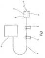
- FIG. 1schematically an implantable device 10 is shown, wherein the dimensions are not reproduced to scale.
- the device 10is connected via a cable 11 to a supply unit 12, which supplies the device 10 with electrical energy and with control signals.
- a supply unit 12which supplies the device 10 with electrical energy and with control signals.
- fastening tabs 14are provided, with which the cable can be attached to the body of the person to which the implant 10 is implanted.
- the device 10is an active retina implant 15, which has as a base body a foil 16 on which electrodes 17 for emitting stimulation signals to excitable cells are arranged.
- the retina implant 15 off Fig. 1is intended to be implanted in a human eye 18 which is in Fig. 2 is shown very schematically. For the sake of simplicity, only the lens 19 and the retina 21 are shown, into which the implant 15 has been implanted.
- the implant 15is preferably introduced into the so-called subretinal space which forms between the pigment epithelium and the photoreceptor layer. If the photoreceptor layer is degenerate or lost, the subretinal space forms between the pigment epithelium and the bipolar and horizontal cell layer.
- the retina implant 15is placed so that over the in Fig. 1 17 stimulation signals can be exerted on cells in the retina 21.
- the beam pathis seen at 23, is passed through the lens 19 to the implant 15, where the visible light 2 is converted into electrical signals, which are converted into stimulation signals.
- the supply unit 12is then fastened in a manner not shown in detail outside the eye, for example on the skull of the patient. Via the supply unit 12, electrical energy is sent to the implant 10, wherein at the same time control signals can also be transmitted which influence the functioning of the implant, as described, for example, in the introduction WO 2005/000395 A1 is described, the content of which is hereby made the subject of the present application.
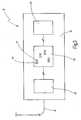
- Fig. 3is schematically the structure of the active retinal implant 15 from Fig. 1 shown.
- an input stage 25is first to recognize, which is supplied via the cable 11 from the outside external external energy.
- the input stage 15is connected to a sensor unit 26, which in this case has a multiplicity of image cells 27 which convert incident visible light into electrical signals, which are then delivered via the electrodes 17 indicated next to the respective image cells to neurons of the retina.
- the processing of the useful signals generated by the image cells 27takes place in an output stage 28, which generates the corresponding stimulation signals, which are then fed back to the sensor unit 26 and the electrodes 17.
- FIG. 3is merely a schematic representation of the retinal implant 15 showing the logical structure, the actual geometric arrangement of the individual components may result in, for example, each image cell 27 having an output stage in the immediate vicinity.
- the electrodes 17may be formed, for example, as needle electrodes 29 and arranged in a separate array 31 on a base body 32, as now in Fig. 4 shown above.
- the needle electrodes 29have, for example, a diameter of 10 .mu.m and a height above the base body 32 of 70 .mu.m, wherein they taper towards the top.
- the electrodes 17are covered by a protective layer 33, which consists of a biodegradable and / or bioresorbable material with a defined degradation rate.
- a protective layer 33which consists of a biodegradable and / or bioresorbable material with a defined degradation rate.
- biologically active substancesare stored, which are released in the dissolution of the protective layer 33.
- the biologically active substanceshave an anti-inflammatory effect, whereby they also have a promoting or inhibiting effect on cell growth.
- a steroidsuch as cortisone and / or dexamethasone is embedded in the protective layer 33.
- This main body 32is now implanted in tissue indicated at 34, for which purpose it is introduced into an incision 35.
- the base body 32is held on a support 36, via which the retina implant 15 is now pushed into the incision 35, as shown in the middle illustration of Fig. 4 is shown.
- the incision 35now presses on the implant 15, whereby the protective layer 33 comes into contact with the tissue 34 and gradually degrades. As the protective layer 33 degrades, the needle electrodes 29 penetrate the tissue 34 until the needle electrodes 29 are finally fully received within the tissue 34, as shown in FIG Fig. 4 shown below.
- the electrodes 17are therefore protected by the protective layer 33, wherein at the same time structures of the tissue 34 during insertion can not be violated.
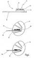
- Fig. 5is again shown schematically the penetration of the needle electrodes 29 in a tissue 34, which is ex vivo .
- the Retina implant 15can be used when it is tested ex vivo , for example.
- each electrode 17in each case comprises a base electrode 37, from which a plurality of needle electrodes 29 protrude.
- planar electrode 38which serves the ground connection of the implant 15 to the tissue 34, as is known per se.
- the retina implantis eg. By its weight or one from the outside, ie in Fig. 5 pressed onto the fabric from above, so that the needle electrodes 29 slowly advance into the tissue 34 when the protective layer 33 is degraded.
- the degradation of the protective layer 33can be effected solely by the contact with the fabric 34, whereby it is also possible to trigger the degradation by chemical, biological or physical processes.
Landscapes
- Health & Medical Sciences (AREA)
- Nuclear Medicine, Radiotherapy & Molecular Imaging (AREA)
- Life Sciences & Earth Sciences (AREA)
- Heart & Thoracic Surgery (AREA)
- Engineering & Computer Science (AREA)
- Biomedical Technology (AREA)
- Veterinary Medicine (AREA)
- Radiology & Medical Imaging (AREA)
- Cardiology (AREA)
- Animal Behavior & Ethology (AREA)
- General Health & Medical Sciences (AREA)
- Public Health (AREA)
- Ophthalmology & Optometry (AREA)
- Electrotherapy Devices (AREA)
- Prostheses (AREA)
Abstract
Description
Translated fromGermanDie vorliegende Erfindung betrifft ein aktives Retina-Implantat mit einer Vielzahl von Bildzellen, die einfallendes Licht in elektrische Signale umwandeln, die über Elektroden an umgebendes Gewebe abgegeben werden, wobei die Elektroden Nadelelektroden sind, die als Array auf einem Grundkörper angeordnet sind.The present invention relates to an active retina implant having a plurality of image cells that convert incident light into electrical signals that are delivered via electrodes to surrounding tissue, wherein the electrodes are needle electrodes that are arranged as an array on a base body.
Ein solches Retina-Implantat ist beschrieben in
Ein aktives Retina-Implantat ist beispielsweise auch aus der
Da derartige kabellose Retina-Implantate für Anwendungen am Menschen jedoch nicht mit einer zufriedenstellenden Qualität zur Verfügung stehen, werden zurzeit nicht nur epiretinale sondern auch subretinale Implantate vorgeschlagen, denen die erforderliche Fremdenergie über Kabel zugeführt wird,However, as such wireless retinal implants are not of satisfactory quality for human applications, at present not only epiretinal but also subretinal implants are proposed to which the required external energy is supplied by cable.
So beschreiben
Auch Sachs et al., a.a.O. beschreiben Verfahren zur subretinalen Implantation, bei denen Folienelektroden in die Netzhaut, also zwischen Pigmentepitel und neuronale Netzhaut eingeschoben werden. Hierbei muss besonders darauf geachtet werden, dass das Implantat während des Einführens nicht geschädigt wird und dass die Netzhaut durch das mechanische Einschieben zwischen die Zellschichten nicht verletzt wird.Also, Sachs et al., Supra. describe methods for subretinal implantation in which foil electrodes are inserted into the retina, ie between the pigment epithelium and the neuronal retina. Care must be taken to ensure that the implant is not damaged during insertion and that the retina is not injured by mechanical intercalation between the cell layers.
Aus der
Bei dem bekannten Herzschrittmacher diffundiert das Steroid aus der dünnen Schutzschicht in das angrenzende Gewebe, wodurch mögliche Entzündungsprozesse unterdrückt werden und der Einheilungsprozess der Elektrode in das Trabekelwerk des Herzmuskels unterstützt wird. Die Schutzschicht ist chemisch und thermisch stabil und hat sich als gewebe- und körperverträglich erwiesen, so dass sie bei einer langen Verweilzeit des Implantates im Körper für eine dauerhafte Abdeckung der porösen Oberfläche der Elektrode dient und diese vor Verunreinigungen schützt, wobei ein Kapazitätsverlust der porösen Elektrodenoberfläche nicht auftritt.In the known pacemaker, the steroid diffuses from the thin protective layer into the adjacent tissue, which suppresses possible inflammatory processes and supports the healing process of the electrode in the heart muscle trabecular meshwork. The protective layer is chemically and thermally stable and has been found to be tissue and biocompatible so that it will provide a long term residence time of the implant in the body for permanent coverage of the porous surface of the electrode and protect it from contamination, with a loss of capacity of the porous electrode surface does not occur.
Retina-Implantate und Herzschrittmacher erfordern eine stabile, langzeitbeständige und funktionelle Kopplung des elektronischen mit dem biologischen System. Dies wird üblicherweise durch eine möglichst enge mechanische Kopplung der Elektroden mit dem umgebenden Gewebe erreicht, wobei die Elektrodenoberfläche häufig mit einer porösen Struktur mit möglichst großer innerer Oberfläche ausgestattet wird, so dass sie eine möglichst große Ladungsübertragungskapazität über die Helmholtz-Doppelschicht an der Grenzfläche zwischen Elektrode und im Gewebe vorhandenen Elektrolyt besitzen.Retinal implants and pacemakers require stable, long-term and functional coupling of the electronic and biological systems. This is usually achieved by the closest possible mechanical coupling of the electrodes to the surrounding tissue, wherein the electrode surface is often provided with a porous structure with the largest possible inner surface, so that they have the largest possible charge transfer capacity on the Helmholtz double layer at the interface between the electrode and existing in the tissue electrolyte.
Bei Implantaten mit einer großen Elektrodendichte, wie beispielsweise bei Retina-Implantaten, ist die Fläche der einzelnen Elektroden jedoch so klein, dass auch bei einer porösen Struktur die Ladungsübertragungskapazität nicht immer ausreicht, sondern dass elektrochemische Effekte an der Elektrode auftreten, die die Stimulationsschwellen erhöhen und sogar zelltoxisch oder inflammatorisch wirken können.However, in implants with a large electrode density, such as retinal implants, the surface of the individual electrodes is so small that even with a porous structure, the charge transfer capacity is not always sufficient, but that electrochemical effects occur at the electrode, which increase the stimulation thresholds and may even be cytotoxic or inflammatory.
Die enge mechanische Kopplung mit den zu stimulierenden Zielzellen ist bei planaren Mikroelektroden, die nicht in das angrenzende Gewebe eindringen können, darüber hinaus eingeschränkt. Insbesondere dann, wenn die Elektroden noch durch nichterregbare Zellschichten von den Zielzellen isoliert sind, kann das die Stimulationsschwellen erheblich erhöhen. Dieses Problem tritt insbesondere bei Retina-Implantaten auf, wo beispielsweise die abgestorbenen Photorezeptoren oder mögliche Glianarben den engen mechanischen Kontakt zwischen den Elektroden und den zu stimulierenden Neuronen behindern.The close mechanical coupling with the target cells to be stimulated is also limited in the case of planar microelectrodes which can not penetrate into the adjacent tissue. In particular, when the electrodes are still isolated from the target cells by non-excitable cell layers, this can significantly increase the stimulation thresholds. This problem especially occurs in retinal implants, where, for example, the dead photoreceptors or possible glial colors hinder the close mechanical contact between the electrodes and the neurons to be stimulated.
Um die Elektroden näher an die zu stimulierenden Zellen heranzubringen, die sich innerhalb des Gewebevolumens befinden, werden daher im Stand der Technik Nadelelektroden vorgeschlagen, die in das Gewebe eindringen sollen. Auf diese Weise werden die zum Erreichen der erforderlichen Reizschwellen benötigten Reizstärken verringert und die Ortsauflösung erhöht.In order to bring the electrodes closer to the cells to be stimulated, which are located within the tissue volume, needle electrodes are therefore proposed in the prior art, which are to penetrate into the tissue. In this way, the stimuli needed to reach the required stimulation thresholds are reduced and the spatial resolution is increased.
Die eingangs erwähnte Veröffentlichung von D. Palanker et al. beschreibt die Verwendung von penetrierenden Elektroden bei subretinalen Implantaten. Die dabei eingesetzten Elektroden haben einen Durchmesser im Bereich von 10 µm und eine Höhe über dem Grundkörper im Bereich von 70 µm. Die Autoren konnten zeigen, dass nach einer Implantation eines Arrays von derartigen Nadelelektroden in den subretinalen Raum einer Ratte eine selbständige Migration der Zellen in die Zwischenräume zwischen den Elektroden zu beobachten war.The above-mentioned publication by D. Palanker et al. describes the use of penetrating electrodes in subretinal implants. The electrodes used have a diameter in the range of 10 microns and a height above the body in the range of 70 microns. The authors were able to show that after implantation of an array of such needle electrodes into the subretinal space of a rat, an independent migration of the cells into the interstices between the electrodes was observed.
Bei dem Einsatz von Nadelelektroden ist es weiter sowohl bei deren Verwendung auf Implantaten als auch im Zusammenhang mitex vivo zu verwendenden Vorrichtungen von besonderer Bedeutung, dass die Nadelspitzen beim Eindringen in das Gewebe keine Zellen innerhalb des Gewebeverbundes verletzen.With the use of needle electrodes, it is of particular importance both in their use on implants and in connection with devices to be usedex vivo that the needle tips do not injure cells within the tissue bundle when they penetrate into the tissue.
Wie bereits eingangs erwähnt, kommt es nach der Implantation von Elektroden häufig zu einer Vemarbung an der Grenzfläche zwischen Elektrode und Gewebe, wodurch sich die elektrischen Eigenschaften dieser Grenzschicht nachteilig verändern. Die Narbenschicht erhöht nämlich zum einen den elektrischen Widerstand des Kontaktes, wobei sich zum anderen dadurch der Abstand zwischen der Elektrodenoberfläche und den Zielzellen vergrößert. Beides hat zur Folge, dass sich die Stimulationseffizienz verringert, was durch erhöhten Ladungsübertrag kompensiert werden muss.As already mentioned at the beginning, implantation of electrodes often leads to scarring at the interface between electrode and tissue, which adversely affects the electrical properties of this boundary layer. Namely, the scar layer firstly increases the electrical resistance of the contact, and on the other hand, the distance between the electrode surface and increases the target cells. Both have the consequence that the stimulation efficiency is reduced, which must be compensated by increased charge transfer.
Die
Neben den Elektroden sind Öffnungen in den Polyimid-Schichten vorgesehen, die bioaktive Spezies aufnehmen können, die dazu dienen, die Schnittstelle auszubilden.Adjacent to the electrodes are openings in the polyimide layers which can receive bioactive species which serve to form the interface.
Die
Vor diesem Hintergrund liegt der vorliegenden Erfindung die Aufgabe zugrunde, das eingangs erwähnte Retina-Implantat derart weiterzubilden, dass es auf schonende Weise so in Kontakt mit dem Gewebe gebracht werden kann, dass die Elektrodenspitzen dicht an die Zielzellen innerhalb des Gewebes herangeführt werden, wo sie dauerhaft stabil platziert werden können.Against this background, the object of the present invention is to refine the retina implant mentioned above in such a way that it can be gently brought into contact with the tissue in such a way that the electrode tips are brought close to the target cells within the tissue, where they are can be placed permanently stable.
Erfindungsgemäß wird diese Aufgabe bei dem eingangs erwähnten Retina-Implantat dadurch gelöst, dass die Elektroden von einer Schutzschicht abegdeckt sind und die Schutzschicht derart beschaffen ist, dass sie sich nach Kontakt mit dem Gewebe auf definierte Weise zumindest so weit auflöst, dass die Elektroden in unmittelbaren Kontakt mit dem Gewebe gelangten, wobei die Schutzschicht biodegradable und/oder bioresorbierbare Materialien mit einer definierten Abbaurate umfasst.According to the invention this object is achieved in the aforementioned retina implant in that the electrodes are covered by a protective layer and the protective layer is such that it dissolves after contact with the tissue in a defined manner at least so far that the electrodes in immediate Contact with the tissue came, wherein the protective layer comprises biodegradable and / or bioresorbable materials with a defined degradation rate.
Die der Erfindung zugrunde liegende Aufgabe wird auf diese Weise vollkommen gelöst.The object underlying the invention is completely solved in this way.
Die Erfinder der vorliegenden Anmeldung haben nämlich erkannt, dass eine sich selbst auflösende Schutzschicht bei der Implantation des Retina-Implantats zunächst nicht nur die Elektroden vor einer Beschädigung im Zusammenhang mit den erforderlichen Manipulationen schützt, sondern dass auch das Gewebe, mit dem die Vorrichtung in Kontakt gebracht wird, zunächst keine Schädigungen erfährt, da die möglicherweise scharfen Spitzen der Elektroden während der Anbringung durch die Schutzschicht abgedeckt sind.Namely, the inventors of the present application have recognized that a self-dissolving protective layer during implantation of the retinal implant initially protects not only the electrodes from damage in connection with the required manipulations, but also the tissue with which the device is in contact initially no damage is experienced because the possibly sharp tips of the electrodes are covered during attachment through the protective layer.
Auf diese Weise ist es also möglich, dass das neue Retina-Implantat zunächst beispielsweise in ein Gewebe implantiert wird, ohne dass die Gefahr besteht, dass die Elektroden oder das Gewebe beschädigt werden.In this way, it is thus possible for the new retina implant to be initially implanted, for example, in a tissue without the risk of damaging the electrodes or the tissue.
Damit kann das erfindungsgemäße Retina-Implantat auch in das Innere von schwer zugänglichen Gewebevoluminas eingebracht werden, ohne dass es während der in der Regel aufwändigen chirurgischen Implantationen mechanisch beschädigt werden.In this way, the retina implant according to the invention can also be introduced into the interior of hard-to-reach tissue volumes without being mechanically damaged during the usually complex surgical implantations.
Unter einer Schutzschicht, die sich "auf definierte Weise auflöst", wird eine Schutzschicht verstanden, die sich gezielt, also gewollt oder auf vorbestimmte Weise, nach dem Kontakt mit dem Gewebe selbst auflöst. Mit anderen Worten, die Schutzschicht wird innerhalb eines Zeitraumes kontinuierlich abgebaut, der zwischen der Herstellung des Kontaktes zwischen Gewebe und Schutzschicht und der Inbetriebnahme der Vorrichtung liegt. Der Abbau der Schutzschicht kann dabei durch chemische, biologische oder physikalische Prozesse ausgelöst werden. Erst nachdem die Vorrichtung also an Ort und Stelle gebracht wurde, beginnt die Schutzschicht sich aufzulösen und die Elektroden werden freigegeben und gelangen allmählich in Kontakt mit dem Gewebe.A protective layer which "dissolves in a defined manner" is understood to mean a protective layer which dissolves deliberately, ie intentionally or in a predetermined manner, after contact with the tissue itself. In other words, the protective layer is continuously degraded within a period of time that lies between the production of the contact between tissue and protective layer and the startup of the device. The degradation of the protective layer can be triggered by chemical, biological or physical processes. Only after the device has been placed in place, the protective layer begins to dissolve and the electrodes are released and gradually come into contact with the tissue.
Mit der erfindungsgemäßen Ausgestaltung des Retina-Implantates ist es jetzt möglich, solche Implantate mit einem Array von hervorstehenden Nadelelektroden zu versehen, ohne dass die genannten Probleme bei der Implantation auftauchen, Nach der Implantation löst sich die Schutzschicht auf, so dass die Schichten der Retina sich langsam an die Nadelspitzen anlagern können, wobei die Nadeln mit zunehmender Auflösung des resorbierbaren Materials weiter in das Gewebe eindringen, ohne dass dadurch Zellen verletzt werden.With the embodiment of the retina implant according to the invention, it is now possible to provide such implants with an array of protruding needle electrodes, without the problems mentioned appear during implantation, After implantation, the protective layer dissolves, so that the layers of the retina itself slowly attach to the needle tips, the needles with increasing dissolution of the resorbable material continue to penetrate into the tissue without causing injury to cells.
Die Erfinder der vorliegenden Anmeldung haben erkannt, dass viele Probleme mit der Implantation derartiger Retina-Implantate vermieden werden können, wenn die in einem Array angeordneten Nadelelektroden in eine sich nach Implantation selbst auflösende Schutzschicht eingebettet werden. Nach Implantation wird die Schicht erfindungsgemäß abgebaut und/oder resorbiert, so dass die Nadelspitzen in Kontakt mit dem Gewebe kommen. Das Material, aus dem die Schutzschicht besteht, ist dabei so ausgewählt bzw. modifiziert, dass die Abbaurate gut definiert ist. Bei dem langsamen Abbau der Schutzschicht werden die Spitzen der Nadelelektroden allmählich immer weiter von der Schutzschicht freigegeben und gelangen in Kontakt mit den Zellen, die entsprechend ihrer Migrationsgeschwindigkeit den Spitzen ausweichen. Die Nadelelektroden dringen also langsam in das Gewebe ein, ohne dieses zu verletzen. Die Penetration wird dabei dadurch unterstützt, dass das Gewebe, in das das Retina-Implantat implantiert wurde, einen Druck auf das Array ausübt, so dass eine Kraft in Richtung der Nadelachsen entsteht.The inventors of the present application have recognized that many problems with the implantation of such retinal implants can be avoided if the arrayed needle electrodes are embedded in a post-implant self-dissolving protective layer. After implantation, the layer is degraded and / or resorbed according to the invention, so that the needle tips come into contact with the tissue. The material from the the protective layer is, is selected or modified so that the degradation rate is well defined. With the slow degradation of the protective layer, the tips of the needle electrodes are gradually freed further and further away from the protective layer and come into contact with the cells, which dodge the tips according to their migration speed. The needle electrodes penetrate slowly into the tissue without injuring it. The penetration is thereby assisted by the fact that the tissue into which the retina implant has been implanted exerts a pressure on the array, so that a force arises in the direction of the needle axes.
Auf diese Weise ist es jetzt auch möglich, Nadelelektroden in tiefer liegende oder schwer zugängliche Gewebeschichten vorzuschieben, ohne dass die Gefahr einer mechanischen Beschädigung der Elektroden bzw. des Gewebes besteht.In this way, it is now possible to advance needle electrodes in deeper or difficult to access tissue layers, without the risk of mechanical damage to the electrodes or the tissue.
Grundsätzlich können Implantate nur von einer frei zugänglichen Oberfläche aus in die gewünschten Gewebeschichten vorgeschoben werden, wobei Elektroden, die senkrecht zur Vorschubrichtung von dem Grundkörper abstehen, durch den mechanischen Vorschub geschädigt werden können, wobei aber andererseits auch die Gefahr besteht, dass diese Elektroden das Gewebe entlang des im Gewebe liegenden Vorschubkanals verletzen.In principle, implants can be advanced only from a freely accessible surface into the desired tissue layers, wherein electrodes that protrude perpendicular to the feed direction of the body, can be damaged by the mechanical feed, but on the other hand there is a risk that these electrodes the tissue along the feed channel in the tissue.
Ferner sind für die Penetration der Nadelelektroden in das Gewebe mechanische Drücke erforderlich, die in Vorschubrichtung auf die Elektroden wirken müssen. Dies bedeutet jedoch, dass im Stand der Technik Nadelelektroden nur in Zellschichten vorgeschoben werden konnten, die von außen mit Hilfe mechanischer Hilfsmittel zugänglich waren; siehe
Zudem sind kontrollierte Eindringgeschwindigkeiten nur schwer herzustellen, wenn die Elektroden nach intrakortikaler Lokalisation langsam in das gewünschte Zellvolumen eindringen sollen, wobei dazu unter Umständen auch tagelange chirurgische Eingriffe erforderlich wären; siehe W. Shain et al., a.a.O.In addition, controlled penetration rates are difficult to produce if the electrodes after intracortical localization slowly penetrate into the desired cell volume, which may also require days of surgical intervention; See W. Shain et al., supra.
Unter einer Nadelelektrode wird im Rahmen der vorliegenden Anmeldung neben langen zylindrischen, sich zu ihrer Spitze ggf. verjüngenden Elektroden auch jede andere Art von Elektroden verstanden, die über den Grundkörper hervorstehen. Die Elektroden können dabei vollständig oder teilweise aus leitfähigen Materialien gefertigt sein, wobei beispielsweise auch nur die Spitze der Elektrode selbst leitfähig ausgebildet sein kann.In the context of the present application, a needle electrode is understood as meaning, in addition to long cylindrical electrodes, which possibly taper towards their tip, also any other type of electrodes which protrude beyond the base body. The electrodes can be made wholly or partly of conductive materials, for example, only the tip of the electrode itself may be formed conductive.
Unter einem Grundkörper wird im Rahmen der vorliegenden Erfindung beispielsweise eine flexible Folie verstanden, auf der neben den Elektroden auch noch verschiedene elektronische Komponenten aufgebracht sind. Der Grundkörper kann aber auch aus jedem anderen, auch steifen Material gefertigt sein. Schließlich ist es auch nicht erforderlich, dass auf dem Grundkörper zusätzlich zu den Elektroden noch weitere elektronische Komponenten angeordnet sind, der Grundkörper kann also lediglich das Elektrodenarray enthalten, wobei das Elektrodenarray über mehradrige Zuleitungen, beispielsweise ein Flachbandkabel, mit einer Stimulations- und/oder Messelektronik verbunden ist.In the context of the present invention, a basic body is understood, for example, to mean a flexible film on which not only the electrodes but also various electronic components are applied. The main body can also be made of any other, even rigid material. Finally, it is also not necessary for further electronic components to be arranged on the base body in addition to the electrodes, so that the base body can only contain the electrode array, the electrode array being provided with multi-core supply lines, for example a ribbon cable, with stimulation and / or measuring electronics connected is.
Die Elektroden haben an ihrer Spitze dabei vorzugsweise Abmessungen in der Größenordnung von zellulären Strukturen wie Axonen, Dendriten oder Zellkörpem, sie sind im Durchmesser vorzugsweise im Bereich von 1 bis 10 µm angesiedelt.The electrodes preferably have dimensions on the top of the order of cellular structures such as axons, dendrites or cell bodies, they are preferably in the range of 1 to 10 microns in diameter.
Um die Nadelelektroden genügend weit in das Gewebe vortreiben zu können, sind die Elektroden vorzugsweise nadelförmig ausgebildet und weisen Längen im Bereich von bis zu mehreren 10 µm auf.In order to drive the needle electrodes sufficiently far into the tissue, the electrodes are preferably needle-shaped and have lengths in the range of up to several 10 microns.
Weil die Schutzschicht biodegradable und/oder bioresorbierbare Materialien mit einer definierten Abbaurate umfasst, ist von Vorteil, dass derartige Materialien eine geringe Abbaurate haben, so dass der langsame Abbau der Schutzschicht die kontrollierte langsame Penetration der Elektroden in das Gewebe ermöglicht, wobei der Anpressdruck durch das sozusagen auf der anderen Seite der Vorrichtung liegende Gewebe ausgeübt wird. Mit anderen Worten, die Geschwindigkeit, mit der die Elektroden, vorzugsweise die Nadeln, in das Gewebe eindringen, wird durch die Rate bestimmt, mit der die Schutzschicht abgebaut wird.Because the protective layer comprises biodegradable and / or bioresorbable materials with a defined degradation rate, it is advantageous that such materials have a low degradation rate, so that the slow degradation of the protective layer allows the controlled slow penetration of the electrodes into the tissue, wherein the contact pressure by the so to speak, tissue lying on the other side of the device is exerted. In other words, the rate at which the electrodes, preferably the needles, penetrate the tissue is determined by the rate at which the protective layer is degraded.
Biodegradable und bioresorbierbare Materialien sind an sich bekannt, sie werden bei der Herstellung und Verwendung von biomedizinischen Implantaten vielfach eingesetzt. Sie zeichnen sich durch ihre Biokompatibilität und ihre natürliche Fähigkeit aus, sich im Laufe der Zeit im Gewebe zu zersetzen. Sie kommen in der Orthopädie, Wundversorgung oder bei Drug Delivery zum Einsatz. Die gebräuchlichsten Materialien sind Polylactic acid (PLA), Polyglycolic acid (PGA) und ihre Co-Polymere sowie Polycaprolactone (PCL). Die Schutzschicht kann darüber hinaus auch Gelatine beinhalten oder im Wesentlichen aus Gelatine bestehen.Biodegradable and bioabsorbable materials are known per se and are widely used in the manufacture and use of biomedical implants. They are characterized by their biocompatibility and their natural ability to disintegrate in the tissue over time. They are used in orthopedics, wound care or drug delivery. The most commonly used materials are polylactic acid (PLA), polyglycolic acid (PGA) and their co-polymers as well as polycaprolactones (PCL). The protective layer may also include gelatin or consist essentially of gelatin.
Der Einsatz dieser Polyester in der Schutzschicht ist besonders bevorzugt, da sie besonders leicht durch einfache Hydrolyse degradieren, die Hydrolyseprodukte durch normale metabolische Prozesse resorbiert werden, und sie es außerdem ermöglichen, die Abbaurate gezielt einzustellen. Bestimmende Faktoren für die Abbaurate sind neben der genauen molekularen Struktur das Verhältnis der Co-Polymere zueinander, das Molekulargewicht und ggf. auch das Herstellungsverfahren selbst. Die Abbauraten dieser Polymere liegen im Bereich von 1 bis 24 Monaten.The use of these polyesters in the protective layer is particularly preferred because they are particularly easy to degrade by simple hydrolysis, the hydrolysis products are absorbed by normal metabolic processes, and they also make it possible to set the degradation rate targeted. Determining factors for the rate of degradation are, in addition to the exact molecular structure, the ratio of the co-polymers to one another, the molecular weight and possibly also the preparation process itself. The degradation rates of these polymers are in the range from 1 to 24 months.
Einen Überblick über im Rahmen der vorliegenden Erfindung verwendbare Materialien liefern
Bioresorbierbare Materialien für biomedizinische Anwendungen sowie biodegradierbare Polyester sind darüber hinaus im Stand der Technik vielfach beschrieben. Im Gegensatz zu reinen Polymeren weisen beispielsweise Implantate aus biodegradierbaren Polyestern (Poly(L-lactid) und Poly(D,L-lactid)) sowie amorphem, carbonathaltigem Calciumphosphat bzw. Calciumcarbonat den Vorteil auf, dass sie beim Abbau keine sauren Produkte freisetzen sondern einen physiologischen pH-Wert aufweisen, da die entstehenden Säuren durch den anorganischen Füllstoff abgepuffert werden; siehe beispielsweise
Gut geeignet sind ferner bioresorbierbare Schichten aus Metall bzw. Metall-Legierungen, wie z.B. Magnesium und Magnesium-Legierung (siehe www.unics.unihannover.de/analytik/Forschung/Bioresorbierbare%20Iplantate.pdf).Also suitable are bioresorbable layers of metal or metal alloys, such as magnesium and magnesium alloy (see www.unics.unihannover.de/analytik/Research/Bioresorbable%20Iplantate.pdf).
Aus der
In vergleichbarer Weise offenbart die
Weder in der
Die Verwendung von biodegradablen und/oder bioresorbierbaren Materialien als sozusagen vorübergehende Schutzschicht auf einem Array von Nadelelektroden bei einer implantierbaren Vorrichtung ist im Stand der Technik jedoch bisher nicht beschrieben.However, the use of biodegradable and / or bioresorbable materials as a kind of temporary protective layer on an array of needle electrodes in an implantable device has hitherto not been described in the prior art.
In einer Weiterbildung ist es bevorzugt, wenn in die Schutzschicht biologisch aktive Substanzen eingelagert sind, die bei der Auflösung der Schutzschicht freigesetzt werden.In a development, it is preferred if biologically active substances are incorporated in the protective layer, which are released during the dissolution of the protective layer.
Bei dieser Maßnahme ist von Vorteil, dass bei dem Abbau der Schutzschicht gleichzeitig aktive Substanzen in das umgebende Gewebe abgegeben werden können, die beispielsweise die Narbenbildung verhindern oder entzündungshemmend wirken.In this measure, it is advantageous that at the same time active substances can be released into the surrounding tissue during the degradation of the protective layer, which, for example, prevent the formation of scars or have an anti-inflammatory effect.
Besonders bevorzugt ist es, wenn die aktive Substanz ein entzündungshemmendes Steroid ist, wie es beispielsweise aus der eingangs erwähnten
Allgemein ist es bevorzugt, wenn die Elektrode eine Grundelektrode umfasst, von der eine Vielzahl von Nadelelektroden abstehen.In general, it is preferable if the electrode comprises a base electrode from which a plurality of needle electrodes protrude.
Bei dieser Maßnahme ist von Vorteil, dass eine mechanisch engere Kopplung mit den zu stimulierenden Zielzellen erreicht wird als bei der Grundelektrode selbst. Ferner ist eine niedrigere Reizschwelle erforderlich, denn die Oberfläche der Grundelektrode erstreckt sich sozusagen zu den Zielzellen wie die im biologischen Gewebe an Nervenzellen vorhandenen Dendriten, wobei die Elektroden auch eine ähnliche Größenordnung aufweisen.In this measure, it is advantageous that a mechanically closer coupling is achieved with the target cells to be stimulated than with the base electrode itself. Furthermore, a lower stimulus threshold is required, because the surface of the base electrode extends, so to speak, to the target cells, as in the biological tissue to nerve cells existing dendrites, wherein the electrodes also have a similar magnitude.
Es handelt sich damit sozusagen um eine dreidimensionale Nanoelektrode, bei der die Vielzahl von Nadelelektroden, die sozusagen einen nanoskaligen Teil der Elektrode darstellen, möglichst schonend in die angrenzende Zellschicht eindringen kann.It is, so to speak, a three-dimensional nanoelectrode in which the multiplicity of needle electrodes, which so to speak represent a nanoscale part of the electrode, can penetrate as gently as possible into the adjacent cell layer.
Derartige Nanoelektrodenstrukturen aus einer planaren Grundelektrode mit einer Vielzahl von abstehenden Nadelelektroden können beispielsweise auf an sich in anderem Zusammenhang bekannte Art und Weise mit einem Elektronenstrahlschreiber durch Elektronenstrahlbelichtung entsprechender Masken und anschließendes Plasma-Ätzen hergestellt oder mit einem FIB- (Focussed Ion Beam) Gerät direkt geätzt oder reaktiv abgeschieden werden.Such nanoelectrode structures of a planar base electrode with a plurality of projecting needle electrodes can, for example, in a manner known per se in another context with an electron beam writer by electron beam exposure of corresponding masks and subsequent Plasma etching can be prepared or directly etched or reactive deposited with a FIB (Focussed Ion Beam) device.
Andererseits ist es auch möglich, die dreidimensionale Nanoelektrodenstruktur in UV-härtbarem Polymer auszubilden, das im Spincoating-Verfahren auf eine Substratoberfläche aufgebracht wird. In das Polymer wird dazu ein Nanostempel angedrückt, danach das Polymer ausgehärtet und schließlich entformt. Die so in das Polymer im Nanoprint-Verfahren eingebrachte Nanostruktur wird anschließend mit dem Elektrodenmaterial durch reaktives Sputtern mit TiN, Ir oder IrO beschichtet. Nach dem Aufbringen des Steroids kann die Struktur dann mit dem biodegradablen Material beschichtet werden.On the other hand, it is also possible to form the three-dimensional nanoelectrode structure in UV-curable polymer, which is applied to a substrate surface by the spin-coating method. In the polymer to a nanostamp is pressed, then the polymer cured and finally demolded. The nanostructure thus introduced into the polymer in the nanoprint process is subsequently coated with the electrode material by reactive sputtering with TiN, Ir or IrO. After application of the steroid, the structure can then be coated with the biodegradable material.
Der Nanostempel muss also nur einmal beispielsweise durch Elektronenstrahlschreiben hergestellt werden, wobei mit dem Nanostempel dann im Prinzip beliebig viele Nanostrukturen hergestellt werden können.The nanostimus must therefore be produced only once, for example, by electron beam writing, with the nanostimple then in principle any number of nanostructures can be produced.
Allgemein ist es noch bevorzugt, wenn die Elektrode aus einem flexiblen Material gefertigt ist.In general, it is still preferable if the electrode is made of a flexible material.
Bei dieser Maßnahme ist von Vorteil, dass aufgrund der anfänglich auf dem Grundkörper vorgesehenen, die Elektroden abdeckenden Schutzschicht auch flexible Elektroden für Implantate verwendet werden können, ohne dass die Gefahr besteht, dass bei der Handhabung der Vorrichtung die flexiblen Elektroden beschädigt werden. Flexible Elektroden haben darüber hinaus den Vorteil, dass sie bei der Auflösung der Schutzschicht selbst bestimmten Strukturen im Gewebe ausweichen können, so dass sie eine schonende Penetration ermöglichen.In this measure, it is advantageous that flexible electrodes for implants can also be used on account of the protective layer initially covering the base body and covering the electrodes, without the risk of damaging the flexible electrodes during handling of the device. In addition, flexible electrodes have the advantage that they can avoid even certain structures in the tissue during the dissolution of the protective layer so that they allow a gentle penetration.
Die Flexibilität des Materials kann dabei sowohl durch Materialeigenschaften als auch durch die Abmaße des Materials erreicht werden, besonders dünne Nadelelektroden weisen beispielsweise auch dann eine gewisse Flexibilität auf, wenn sie aus Metall gefertigt sind.The flexibility of the material can be achieved both by material properties and by the dimensions of the material, particularly thin needle electrodes For example, they have some flexibility even if they are made of metal.
Allgemein ist es dann noch bevorzugt, wenn auf dem Grundkörper zumindest eine planare Elektrode vorgesehen ist.In general, it is then preferred if at least one planar electrode is provided on the base body.
Diese planare Elektrode kann in an sich bekannter Weise der Masseverbindung des Retina-Implantats mit dem umgebenden Gewebe dienen. Dabei ist es einerseits möglich, die nadelförmigen Elektroden und die planare Elektrode auf unterschiedlichen Seiten des Grundkörpers anzuordnen, wobei es auch möglich ist, beide Elektrodenarten auf der selben Seite des Grundkörpers anzuordnen.This planar electrode can serve in a manner known per se for the ground connection of the retina implant with the surrounding tissue. It is on the one hand possible to arrange the needle-shaped electrodes and the planar electrode on different sides of the base body, wherein it is also possible to arrange both types of electrodes on the same side of the base body.
Weitere Vorteile ergeben sich aus der Beschreibung und der beigefügten Zeichnung.Further advantages will become apparent from the description and the accompanying drawings.
Es versteht sich, dass die vorstehend genannten und die nachstehend noch zu erläuternden Merkmale nicht nur in der jeweils angegebenen Kombination, sondern auch in anderen Kombinationen oder in Alleinstellung verwendbar sind, ohne den Rahmen der vorliegenden Erfindung zu verlassen.It is understood that the features mentioned above and those yet to be explained below can be used not only in the particular combination given, but also in other combinations or in isolation, without departing from the scope of the present invention.
Ein Ausführungsbeispiel der Erfindung ist in der Zeichnung dargestellt und wird in der nachfolgenden Beschreibung näher erläutert. Es zeigen:
- Fig. 1
- in schematischer Darstellung einer implantierbaren Vorrichtung, hier ein Retina-Implantat, in nicht maßstabgetreuer Darstellung;
- Fig. 2
- eine schematische Darstellung eines menschlichen Auges, in das das Retina-Implantat gemäß
Fig. 1 eingesetzt ist, ebenfalls nicht maßstabgetreu; - Fig. 3
- eine schematische Darstellung des Retina-Implantates aus
Fig. 1 ; - Fig. 4
- eine schematische Darstellung der Implantation des Retina-Implantates aus
Fig. 3 in umgebendes Gewebe; und - Fig. 5
- eine schematische Darstellung der Kontaktierung eines Elektrodenarrays mit einem Gewebeex vivo.
- Fig. 1
- in a schematic representation of an implantable device, here a retina implant, not to scale;
- Fig. 2
- a schematic representation of a human eye, in which the retina implant according to
Fig. 1 is also not true to scale; - Fig. 3
- a schematic representation of the retina implant
Fig. 1 ; - Fig. 4
- a schematic representation of the implantation of the retina implant
Fig. 3 in surrounding tissue; and - Fig. 5
- a schematic representation of the contacting of an electrode array with a tissueex vivo.
In
Die Vorrichtung 10 ist ein aktives Retina-Implantat 15, das als Grundkörper eine Folie 16 aufweist, auf der Elektroden 17 zur Abgabe von Stimulationssignalen an erregbare Zellen angeordnet sind.The
Das Retina-Implantat 15 aus
Durch einen Pfeil 22 angedeutetes sichtbares Licht, dessen Strahlengang bei 23 zu sehen ist, wird über die Linse 19 auf das Implantat 15 geleitet, wo das sichtbare Licht 2 in elektrische Signale umgewandelt wird, die in Stimulationssignale gewandelt werden.Indicated by an
Es ist zu erkennen, dass das Kabel 11 seitlich aus dem Auge herausgeführt und dort außen auf der Sklera 24 mit den Befestigungslaschen 14 befestigt wird, bevor das Kabel weiter zu der externen Versorgungseinheit 12 führt.It can be seen that the
Die Versorgungseinheit 12 wird dann in nicht näher gezeigter Art und Weise außerhalb des Auges beispielsweise am Schädel des Patienten befestigt. Über die Versorgungseinheit 12 wird elektrische Energie zu dem Implantat 10 gesandt, wobei gleichzeitig auch Steuersignale übermittelt werden können, die die Funktionsweise des Implantates so beeinflussen, wie dies beispielsweise in der eingangs erwähnten
Es sei noch erwähnt, dass die Abmaße insbesondere des Retina-Implantates 15, der Befestigungslaschen 14 sowie der externen Versorgungseinheit 12 in den
In
Die Verarbeitung der von den Bildzellen 27 erzeugten Nutzsignale erfolgt in einer Ausgangsstufe 28, die die entsprechenden Stimulationssignale erzeugt, die dann zurück zu der Sensoreinheit 26 bzw. den Elektroden 17 geführt werden.The processing of the useful signals generated by the
In diesem Zusammenhang sei darauf hingewiesen, dass die
Die Elektroden 17 können beispielsweise als Nadelelektroden 29 ausgebildet und in einem gesonderten Array 31 auf einem Grundkörper 32 angeordnet sein, wie dies jetzt in
Die Elektroden 17 sind dabei von einer Schutzschicht 33 abgedeckt, die aus einem biodegradablen und/oder bioresorbierbaren Material mit einer definierten Abbaurate besteht. In die Schutzschicht 33 sind biologisch aktive Substanzen eingelagert, die bei der Auflösung der Schutzschicht 33 freigesetzt werden.The
Die biologisch aktiven Substanzen wirken entzündungshemmend, wobei sie auch fördernd oder hemmend auf das Zellwachstum wirken. In vielen Fällen wird ein Steroid wie Cortison und/oder Dexamethason in die Schutzschicht 33 eingebettet.The biologically active substances have an anti-inflammatory effect, whereby they also have a promoting or inhibiting effect on cell growth. In many cases, a steroid such as cortisone and / or dexamethasone is embedded in the
Dieser Grundkörper 32 wird jetzt in bei 34 angedeutetes Gewebe implantiert, wozu er in einen Einschnitt 35 eingeführt wird.This
Der Grundkörper 32 ist dabei auf einem Träger 36 gehalten, über den das Retina-Implantat 15 jetzt in den Einschnitt 35 hineingeschoben wird, wie dies in der mittleren Abbildung der
Der Einschnitt 35 drückt jetzt auf das Implantat 15, wodurch die Schutzschicht 33 in Kontakt mit dem Gewebe 34 gelangt und sich allmählich abbaut. In dem Maße, wie sich die Schutzschicht 33 abbaut, dringen die Nadelelektroden 29 in das Gewebe 34 ein, bis die Nadelelektroden 29 schließlich vollständig in dem Gewebe 34 aufgenommen sind, wie dies in
Während des Einschiebens des Implantates 15 in das Gewebe 34 sind die Elektroden 17 also durch die Schutzschicht 33 geschützt, wobei gleichzeitig auch Strukturen des Gewebes 34 beim Einschieben nicht verletzt werden können.During the insertion of the
In
In
Ferner ist schematisch auf dem Implantat in
Die Herstellung des Elektrodenarrays 31 aus
Das Retina Implantat wird dabei bspw. durch sein Gewicht oder eine von außen, also in
Der Abbau der Schutzschicht 33 kann allein durch den Kontakt mit dem Gewebe 34 bewirkt werden, wobei es auch möglich ist, den Abbau durch chemische, biologische oder physikalische Prozesse auszulösen.The degradation of the
Claims (7)
- An active retinal implant (15) comprising a multiplicity of image cells (27) that convert incident light (22) into electrical signals, which electrical signals are delivered via electrodes (17) to surrounding tissue (21, 34), wherein said electrodes (17) are needle electrodes (29) arranged as an array (31) on a base body (15, 32),characterized in that said electrodes (17) are covered by a protective layer (33), said protective layer (33) being such that, after contact with the tissue (21, 34), it decomposes in a defined manner and at least to such an extent that said electrodes (17) come into direct contact with said tissue (21, 34), and wherein the protective layer (33) comprises biodegradable and/or bioabsorbable materials having a defined rate of degradation.
- The retinal implant of Claim 1,characterized in that the protective layer (33) comprises polyglycolic acid, L-polylactic acid, D,L-polylactic acid, polycaprolactone, copolymers thereof, gelatin, and/or biodegradable metals and metal alloys, like e.g. magnesium and magnesium alloys.
- The retinal implant of Claim 1 or 2,characterized in that the protective layer (33) incorporates biologically active substances that are released when the protective layer (33) decomposes.
- The retinal implant of Claim 3,characterized in that the biologically active substance is anti-inflammatory and/or acts promoting or inhibiting on cell growth, preferably comprises a steroid, which further preferably comprises cortisone and/or dexamethasone.
- The retinal implant of anyone of Claims 1 to 4,characterized in at the electrode (17) comprises a base electrode (37), a multiplicity of needle electrodes (29) projecting from said base electrode.
- The retinal implant of anyone of Claims 1 to 5,characterized in that the electrode (17) is made from a flexible material.
- The retinal implant of anyone of Claims 1 to 6,characterized in that at least one planar electrode (38) is provided on the base body (32).
Applications Claiming Priority (2)
| Application Number | Priority Date | Filing Date | Title |
|---|---|---|---|
| DE102006048819ADE102006048819A1 (en) | 2006-10-10 | 2006-10-10 | Device with a basic body |
| PCT/EP2007/008435WO2008043439A1 (en) | 2006-10-10 | 2007-09-27 | Device with a base body |
Publications (2)
| Publication Number | Publication Date |
|---|---|
| EP2083911A1 EP2083911A1 (en) | 2009-08-05 |
| EP2083911B1true EP2083911B1 (en) | 2012-01-04 |
Family
ID=38858525
Family Applications (1)
| Application Number | Title | Priority Date | Filing Date |
|---|---|---|---|
| EP07818518ANot-in-forceEP2083911B1 (en) | 2006-10-10 | 2007-09-27 | Retinal implant with a base body |
Country Status (6)
| Country | Link |
|---|---|
| US (1) | US20090192571A1 (en) |
| EP (1) | EP2083911B1 (en) |
| JP (1) | JP2010505563A (en) |
| AT (1) | ATE539793T1 (en) |
| DE (1) | DE102006048819A1 (en) |
| WO (1) | WO2008043439A1 (en) |
Cited By (1)
| Publication number | Priority date | Publication date | Assignee | Title |
|---|---|---|---|---|
| DE102012101337A1 (en)* | 2012-02-20 | 2013-08-22 | Eberhard-Karls-Universität Universitätsklinikum Tübingen | Base, holder, kit and electrode assembly and method of manufacture |
Families Citing this family (51)
| Publication number | Priority date | Publication date | Assignee | Title |
|---|---|---|---|---|
| WO2003002243A2 (en) | 2001-06-27 | 2003-01-09 | Remon Medical Technologies Ltd. | Method and device for electrochemical formation of therapeutic species in vivo |
| US8840660B2 (en) | 2006-01-05 | 2014-09-23 | Boston Scientific Scimed, Inc. | Bioerodible endoprostheses and methods of making the same |
| US8089029B2 (en) | 2006-02-01 | 2012-01-03 | Boston Scientific Scimed, Inc. | Bioabsorbable metal medical device and method of manufacture |
| US8048150B2 (en) | 2006-04-12 | 2011-11-01 | Boston Scientific Scimed, Inc. | Endoprosthesis having a fiber meshwork disposed thereon |
| EP2054537A2 (en) | 2006-08-02 | 2009-05-06 | Boston Scientific Scimed, Inc. | Endoprosthesis with three-dimensional disintegration control |
| ES2357661T3 (en) | 2006-09-15 | 2011-04-28 | Boston Scientific Scimed, Inc. | BIOEROSIONABLE ENDOPROOTHESIS WITH BIOESTABLE INORGANIC LAYERS. |
| EP2959925B1 (en) | 2006-09-15 | 2018-08-29 | Boston Scientific Limited | Medical devices and methods of making the same |
| JP2010503489A (en) | 2006-09-15 | 2010-02-04 | ボストン サイエンティフィック リミテッド | Biodegradable endoprosthesis and method for producing the same |
| WO2008034066A1 (en) | 2006-09-15 | 2008-03-20 | Boston Scientific Limited | Bioerodible endoprostheses and methods of making the same |
| WO2008036548A2 (en) | 2006-09-18 | 2008-03-27 | Boston Scientific Limited | Endoprostheses |
| ES2506144T3 (en) | 2006-12-28 | 2014-10-13 | Boston Scientific Limited | Bioerodible endoprosthesis and their manufacturing procedure |
| US8052745B2 (en) | 2007-09-13 | 2011-11-08 | Boston Scientific Scimed, Inc. | Endoprosthesis |
| US7998192B2 (en) | 2008-05-09 | 2011-08-16 | Boston Scientific Scimed, Inc. | Endoprostheses |
| US8236046B2 (en) | 2008-06-10 | 2012-08-07 | Boston Scientific Scimed, Inc. | Bioerodible endoprosthesis |
| US7985252B2 (en) | 2008-07-30 | 2011-07-26 | Boston Scientific Scimed, Inc. | Bioerodible endoprosthesis |
| US8382824B2 (en) | 2008-10-03 | 2013-02-26 | Boston Scientific Scimed, Inc. | Medical implant having NANO-crystal grains with barrier layers of metal nitrides or fluorides |
| US8150526B2 (en)* | 2009-02-09 | 2012-04-03 | Nano-Retina, Inc. | Retinal prosthesis |
| US8718784B2 (en)* | 2010-01-14 | 2014-05-06 | Nano-Retina, Inc. | Penetrating electrodes for retinal stimulation |
| US8428740B2 (en) | 2010-08-06 | 2013-04-23 | Nano-Retina, Inc. | Retinal prosthesis techniques |
| US8706243B2 (en) | 2009-02-09 | 2014-04-22 | Rainbow Medical Ltd. | Retinal prosthesis techniques |
| US8442641B2 (en) | 2010-08-06 | 2013-05-14 | Nano-Retina, Inc. | Retinal prosthesis techniques |
| EP2403546A2 (en) | 2009-03-02 | 2012-01-11 | Boston Scientific Scimed, Inc. | Self-buffering medical implants |
| DE102009015389A1 (en) | 2009-03-20 | 2010-09-30 | Retina Implant Ag | Active retinal implant for eye for serving to counteract loss of vision due to degenerations of retina, has array of stimulation elements that are designed as radiation-emitting elements |
| EP2408514B1 (en)* | 2009-03-20 | 2017-01-25 | Retina Implant AG | Active retinal implant |
| US8435281B2 (en) | 2009-04-10 | 2013-05-07 | Boston Scientific Scimed, Inc. | Bioerodible, implantable medical devices incorporating supersaturated magnesium alloys |
| EP2440283B1 (en)* | 2009-06-09 | 2018-08-01 | Neuronano AB | Microelectrode and multiple microelectrodes comprising means for releasing drugs into the tissue |
| JP5578540B2 (en)* | 2009-07-31 | 2014-08-27 | 株式会社ニデック | VISUAL PLAYBACK ASSISTANCE DEVICE AND VISUAL PLAYBACK ASSISTANCE DEVICE MANUFACTURING METHOD |
| US8668732B2 (en) | 2010-03-23 | 2014-03-11 | Boston Scientific Scimed, Inc. | Surface treated bioerodible metal endoprostheses |
| US9821159B2 (en) | 2010-11-16 | 2017-11-21 | The Board Of Trustees Of The Leland Stanford Junior University | Stimulation devices and methods |
| JP2013542838A (en) | 2010-11-16 | 2013-11-28 | ザ ボード オブ トラスティーズ オブ ザ レランド スタンフォード ジュニア ユニバーシティー | System and method for treating dry eye |
| EP2476456A1 (en)* | 2011-01-13 | 2012-07-18 | BIOTRONIK SE & Co. KG | Self-Dissolving Electrode or Probe Implant |
| US8571669B2 (en) | 2011-02-24 | 2013-10-29 | Nano-Retina, Inc. | Retinal prosthesis with efficient processing circuits |
| ES2645204T3 (en)* | 2011-04-07 | 2017-12-04 | Oculeve, Inc. | Stimulation devices |
| US9199080B2 (en) | 2011-09-12 | 2015-12-01 | Okuvision Gmbh | Method for treating an eye |
| EP2861145B1 (en)* | 2012-06-14 | 2019-07-24 | Autonomix Medical, Inc. | Devices and systems for diagnosis and treatment of overactive bladder |
| WO2014165124A1 (en) | 2013-03-12 | 2014-10-09 | Oculeve, Inc. | Implant delivery devices, systems, and methods |
| US9370417B2 (en) | 2013-03-14 | 2016-06-21 | Nano-Retina, Inc. | Foveated retinal prosthesis |
| NZ704579A (en) | 2013-04-19 | 2018-10-26 | Oculeve Inc | Nasal stimulation devices and methods |
| US9474902B2 (en) | 2013-12-31 | 2016-10-25 | Nano Retina Ltd. | Wearable apparatus for delivery of power to a retinal prosthesis |
| US9331791B2 (en) | 2014-01-21 | 2016-05-03 | Nano Retina Ltd. | Transfer of power and data |
| US10959631B2 (en)* | 2014-02-01 | 2021-03-30 | Biocircuit Technologies, Inc. | Neural interfacing device |
| ES2812752T3 (en) | 2014-02-25 | 2021-03-18 | Oculeve Inc | Polymer formulations for nasolacrimal stimulation |
| AU2015292278B2 (en) | 2014-07-25 | 2020-04-09 | Oculeve, Inc. | Stimulation patterns for treating dry eye |
| DE102014014942A1 (en)* | 2014-10-07 | 2016-04-07 | Neuroloop GmbH | Implantable arrangement |
| CA2965363A1 (en) | 2014-10-22 | 2016-04-28 | Oculeve, Inc. | Implantable nasal stimulator systems and methods |
| WO2016065211A1 (en) | 2014-10-22 | 2016-04-28 | Oculeve, Inc. | Contact lens for increasing tear production |
| EP3209372B1 (en) | 2014-10-22 | 2020-07-15 | Oculeve, Inc. | Stimulation devices for treating dry eye |
| US10426958B2 (en) | 2015-12-04 | 2019-10-01 | Oculeve, Inc. | Intranasal stimulation for enhanced release of ocular mucins and other tear proteins |
| US10252048B2 (en) | 2016-02-19 | 2019-04-09 | Oculeve, Inc. | Nasal stimulation for rhinitis, nasal congestion, and ocular allergies |
| AU2017260237A1 (en) | 2016-05-02 | 2018-11-22 | Oculeve, Inc. | Intranasal stimulation for treatment of meibomian gland disease and blepharitis |
| WO2018102535A1 (en) | 2016-12-02 | 2018-06-07 | Oculeve, Inc. | Apparatus and method for dry eye forecast and treatment recommendation |
Family Cites Families (17)
| Publication number | Priority date | Publication date | Assignee | Title |
|---|---|---|---|---|
| US679231A (en)* | 1901-02-07 | 1901-07-23 | William Louis Harbach | Type-writer. |
| US4628933A (en)* | 1985-07-23 | 1986-12-16 | Michelson Robin P | Method and apparatus for visual prosthesis |
| US4837049A (en)* | 1986-06-17 | 1989-06-06 | Alfred E. Mann Foundation For Scientific Research | Method of making an electrode array |
| US4827940A (en)* | 1987-04-13 | 1989-05-09 | Cardiac Pacemakers, Inc. | Soluble covering for cardiac pacing electrode |
| EP0388480A1 (en)* | 1989-03-20 | 1990-09-26 | Siemens Aktiengesellschaft | Implantable stimulation electrode |
| US5522876A (en)* | 1994-10-26 | 1996-06-04 | Vitatron Medical, B.V. | Screw-in pacing lead |
| SE9503144D0 (en)* | 1995-09-12 | 1995-09-12 | Pacesetter Ab | Protective body for implantable electrical conductor and electric conductor provided with such end protection |
| US6360129B1 (en)* | 1999-12-13 | 2002-03-19 | Cardiac Pacemakers, Inc. | Mannitol/hydrogel cap for tissue-insertable connections |
| DK1246665T3 (en)* | 2000-01-07 | 2006-01-09 | Biowave Corp | Electromagnetic Therapy Device |
| US6829498B2 (en)* | 2000-03-29 | 2004-12-07 | Arizona Board Of Regents | Device for creating a neural interface and method for making same |
| DE10028522A1 (en)* | 2000-06-08 | 2001-12-20 | Fraunhofer Ges Forschung | Biodegradable neuroelectrode for nerve control has electrode/carrier assembly mounted on cuff of biodegradable material |
| WO2002080816A1 (en)* | 2001-03-30 | 2002-10-17 | Nagoya Ind Science Reserach I | Electrode member for retinal stimulation, and artificial retinal device using the electrode member |
| US7127284B2 (en)* | 2001-06-11 | 2006-10-24 | Mercator Medsystems, Inc. | Electroporation microneedle and methods for its use |
| US6792314B2 (en)* | 2001-06-18 | 2004-09-14 | Alfred E. Mann Foundation For Scientific Research | Miniature implantable array and stimulation system suitable for eyelid stimulation |
| US20050203601A1 (en)* | 2003-02-14 | 2005-09-15 | Daniel Palanker | Neural stimulation array providing proximity of electrodes to cells via cellular migration |
| US7035692B1 (en)* | 2003-04-30 | 2006-04-25 | The Regents Of The University Of California | High density polymer-based integrated electrode array |
| DE10329615A1 (en)* | 2003-06-23 | 2005-03-03 | Eberhard-Karls-Universität Tübingen Universitätsklinikum | Active retina implant with a variety of picture elements |
- 2006
- 2006-10-10DEDE102006048819Apatent/DE102006048819A1/ennot_activeCeased
- 2007
- 2007-09-27EPEP07818518Apatent/EP2083911B1/ennot_activeNot-in-force
- 2007-09-27ATAT07818518Tpatent/ATE539793T1/enactive
- 2007-09-27WOPCT/EP2007/008435patent/WO2008043439A1/enactiveApplication Filing
- 2007-09-27JPJP2009531732Apatent/JP2010505563A/ennot_activeWithdrawn
- 2009
- 2009-04-09USUS12/421,465patent/US20090192571A1/ennot_activeAbandoned
Cited By (3)
| Publication number | Priority date | Publication date | Assignee | Title |
|---|---|---|---|---|
| DE102012101337A1 (en)* | 2012-02-20 | 2013-08-22 | Eberhard-Karls-Universität Universitätsklinikum Tübingen | Base, holder, kit and electrode assembly and method of manufacture |
| WO2013124141A1 (en) | 2012-02-20 | 2013-08-29 | Eberhard-Karls-Universität Tübingen Universitätsklinikum | Electrode arrangement |
| DE102012101337B4 (en)* | 2012-02-20 | 2013-10-31 | Eberhard-Karls-Universität Universitätsklinikum Tübingen | Base, holder, kit and electrode assembly and method of manufacture |
Also Published As
| Publication number | Publication date |
|---|---|
| US20090192571A1 (en) | 2009-07-30 |
| WO2008043439A1 (en) | 2008-04-17 |
| DE102006048819A1 (en) | 2008-04-17 |
| EP2083911A1 (en) | 2009-08-05 |
| JP2010505563A (en) | 2010-02-25 |
| ATE539793T1 (en) | 2012-01-15 |
Similar Documents
| Publication | Publication Date | Title |
|---|---|---|
| EP2083911B1 (en) | Retinal implant with a base body | |
| EP2066396B1 (en) | Implantable multi-electrode device | |
| EP1112095B1 (en) | Biologically active implants | |
| DE69001672T2 (en) | NEUROLOGICAL THERAPY SYSTEM. | |
| DE69737402T2 (en) | Device for the treatment of neurodegenerative disorders | |
| McCreery et al. | Stimulus parameters affecting tissue injury during microstimulation in the cochlear nucleus of the cat | |
| DE10048068A1 (en) | Temporary, medical electrical cable with a biodegradable attachment pad for an electrode, which is loaded with therapeutic medication | |
| DE60029824T2 (en) | Dental prosthesis with means for releasing active substances | |
| DE10048067A1 (en) | Temporary medical electrical lead with a biodegradable attachment pad for an electrode | |
| EP1477203A2 (en) | Epicardial electrode | |
| WO2006116968A2 (en) | Biostable neuroelectrode | |
| EP3784327B1 (en) | Electrode body of an electrode assembly and electrode assembly for electrical stimulation, and method for producing an electrode assembly | |
| WO2008131714A2 (en) | Method and arrangement for electrically contacting an object surrounded by a membrane, using an electrode | |
| EP2509678B1 (en) | Neural prosthesis and method for producing a neural prosthesis | |
| DE102007005817A1 (en) | Biologically active device and process for its preparation | |
| EP2001406A1 (en) | Device for reversibly attaching an implant in an eye | |
| EP2033682A1 (en) | Flexible visual prosthesis and method for manufacturing a flexible visual prosthesis | |
| DE112022002778T5 (en) | SYSTEM AND DEVICE FOR IMPLANT INSERTION WITH OSCILLATION SUPPORT | |
| Thanos et al. | Implantable visual prostheses | |
| DE102011001403A1 (en) | Dental implant and method for producing or processing a dental implant | |
| EP1790379B1 (en) | Retina implant for electrical stimulation of the retina | |
| DE102007020377B4 (en) | Tissue-sparing instrument for stimulation and / or dissipation of bioelectric signals | |
| DE102022129920B3 (en) | Implant system with actively controllable degradation and method for actively controllable degradation of an implant system | |
| DE102009005792B4 (en) | Medical implant with surface coating | |
| AT506651B1 (en) | ATTACHING A MEDICAL IMPLANT IN A PATIENT |
Legal Events
| Date | Code | Title | Description |
|---|---|---|---|
| PUAI | Public reference made under article 153(3) epc to a published international application that has entered the european phase | Free format text:ORIGINAL CODE: 0009012 | |
| 17P | Request for examination filed | Effective date:20090430 | |
| AK | Designated contracting states | Kind code of ref document:A1 Designated state(s):AT BE BG CH CY CZ DE DK EE ES FI FR GB GR HU IE IS IT LI LT LU LV MC MT NL PL PT RO SE SI SK TR | |
| 17Q | First examination report despatched | Effective date:20091116 | |
| DAX | Request for extension of the european patent (deleted) | ||
| GRAP | Despatch of communication of intention to grant a patent | Free format text:ORIGINAL CODE: EPIDOSNIGR1 | |
| RTI1 | Title (correction) | Free format text:RETINAL IMPLANT WITH A BASE BODY | |
| GRAS | Grant fee paid | Free format text:ORIGINAL CODE: EPIDOSNIGR3 | |
| GRAA | (expected) grant | Free format text:ORIGINAL CODE: 0009210 | |
| RAP1 | Party data changed (applicant data changed or rights of an application transferred) | Owner name:RETINA IMPLANT AG | |
| AK | Designated contracting states | Kind code of ref document:B1 Designated state(s):AT BE BG CH CY CZ DE DK EE ES FI FR GB GR HU IE IS IT LI LT LU LV MC MT NL PL PT RO SE SI SK TR | |
| REG | Reference to a national code | Ref country code:GB Ref legal event code:FG4D Free format text:NOT ENGLISH | |
| REG | Reference to a national code | Ref country code:CH Ref legal event code:EP Ref country code:CH Ref legal event code:NV Representative=s name:TROESCH SCHEIDEGGER WERNER AG | |
| REG | Reference to a national code | Ref country code:AT Ref legal event code:REF Ref document number:539793 Country of ref document:AT Kind code of ref document:T Effective date:20120115 | |
| REG | Reference to a national code | Ref country code:IE Ref legal event code:FG4D | |
| REG | Reference to a national code | Ref country code:DE Ref legal event code:R096 Ref document number:502007009005 Country of ref document:DE Effective date:20120308 | |
| REG | Reference to a national code | Ref country code:NL Ref legal event code:VDEP Effective date:20120104 | |
| PG25 | Lapsed in a contracting state [announced via postgrant information from national office to epo] | Ref country code:SI Free format text:LAPSE BECAUSE OF FAILURE TO SUBMIT A TRANSLATION OF THE DESCRIPTION OR TO PAY THE FEE WITHIN THE PRESCRIBED TIME-LIMIT Effective date:20120104 | |
| LTIE | Lt: invalidation of european patent or patent extension | Effective date:20120104 | |
| PG25 | Lapsed in a contracting state [announced via postgrant information from national office to epo] | Ref country code:IS Free format text:LAPSE BECAUSE OF FAILURE TO SUBMIT A TRANSLATION OF THE DESCRIPTION OR TO PAY THE FEE WITHIN THE PRESCRIBED TIME-LIMIT Effective date:20120504 Ref country code:LT Free format text:LAPSE BECAUSE OF FAILURE TO SUBMIT A TRANSLATION OF THE DESCRIPTION OR TO PAY THE FEE WITHIN THE PRESCRIBED TIME-LIMIT Effective date:20120104 Ref country code:NL Free format text:LAPSE BECAUSE OF FAILURE TO SUBMIT A TRANSLATION OF THE DESCRIPTION OR TO PAY THE FEE WITHIN THE PRESCRIBED TIME-LIMIT Effective date:20120104 Ref country code:BG Free format text:LAPSE BECAUSE OF FAILURE TO SUBMIT A TRANSLATION OF THE DESCRIPTION OR TO PAY THE FEE WITHIN THE PRESCRIBED TIME-LIMIT Effective date:20120404 | |
| REG | Reference to a national code | Ref country code:IE Ref legal event code:FD4D | |
| PG25 | Lapsed in a contracting state [announced via postgrant information from national office to epo] | Ref country code:PL Free format text:LAPSE BECAUSE OF FAILURE TO SUBMIT A TRANSLATION OF THE DESCRIPTION OR TO PAY THE FEE WITHIN THE PRESCRIBED TIME-LIMIT Effective date:20120104 Ref country code:GR Free format text:LAPSE BECAUSE OF FAILURE TO SUBMIT A TRANSLATION OF THE DESCRIPTION OR TO PAY THE FEE WITHIN THE PRESCRIBED TIME-LIMIT Effective date:20120405 Ref country code:PT Free format text:LAPSE BECAUSE OF FAILURE TO SUBMIT A TRANSLATION OF THE DESCRIPTION OR TO PAY THE FEE WITHIN THE PRESCRIBED TIME-LIMIT Effective date:20120504 Ref country code:LV Free format text:LAPSE BECAUSE OF FAILURE TO SUBMIT A TRANSLATION OF THE DESCRIPTION OR TO PAY THE FEE WITHIN THE PRESCRIBED TIME-LIMIT Effective date:20120104 Ref country code:FI Free format text:LAPSE BECAUSE OF FAILURE TO SUBMIT A TRANSLATION OF THE DESCRIPTION OR TO PAY THE FEE WITHIN THE PRESCRIBED TIME-LIMIT Effective date:20120104 | |
| PG25 | Lapsed in a contracting state [announced via postgrant information from national office to epo] | Ref country code:CY Free format text:LAPSE BECAUSE OF FAILURE TO SUBMIT A TRANSLATION OF THE DESCRIPTION OR TO PAY THE FEE WITHIN THE PRESCRIBED TIME-LIMIT Effective date:20120104 | |
| PG25 | Lapsed in a contracting state [announced via postgrant information from national office to epo] | Ref country code:EE Free format text:LAPSE BECAUSE OF FAILURE TO SUBMIT A TRANSLATION OF THE DESCRIPTION OR TO PAY THE FEE WITHIN THE PRESCRIBED TIME-LIMIT Effective date:20120104 Ref country code:RO Free format text:LAPSE BECAUSE OF FAILURE TO SUBMIT A TRANSLATION OF THE DESCRIPTION OR TO PAY THE FEE WITHIN THE PRESCRIBED TIME-LIMIT Effective date:20120104 Ref country code:CZ Free format text:LAPSE BECAUSE OF FAILURE TO SUBMIT A TRANSLATION OF THE DESCRIPTION OR TO PAY THE FEE WITHIN THE PRESCRIBED TIME-LIMIT Effective date:20120104 Ref country code:SE Free format text:LAPSE BECAUSE OF FAILURE TO SUBMIT A TRANSLATION OF THE DESCRIPTION OR TO PAY THE FEE WITHIN THE PRESCRIBED TIME-LIMIT Effective date:20120104 Ref country code:IE Free format text:LAPSE BECAUSE OF FAILURE TO SUBMIT A TRANSLATION OF THE DESCRIPTION OR TO PAY THE FEE WITHIN THE PRESCRIBED TIME-LIMIT Effective date:20120104 Ref country code:DK Free format text:LAPSE BECAUSE OF FAILURE TO SUBMIT A TRANSLATION OF THE DESCRIPTION OR TO PAY THE FEE WITHIN THE PRESCRIBED TIME-LIMIT Effective date:20120104 | |
| PLBE | No opposition filed within time limit | Free format text:ORIGINAL CODE: 0009261 | |
| STAA | Information on the status of an ep patent application or granted ep patent | Free format text:STATUS: NO OPPOSITION FILED WITHIN TIME LIMIT | |
| PG25 | Lapsed in a contracting state [announced via postgrant information from national office to epo] | Ref country code:IT Free format text:LAPSE BECAUSE OF FAILURE TO SUBMIT A TRANSLATION OF THE DESCRIPTION OR TO PAY THE FEE WITHIN THE PRESCRIBED TIME-LIMIT Effective date:20120104 Ref country code:SK Free format text:LAPSE BECAUSE OF FAILURE TO SUBMIT A TRANSLATION OF THE DESCRIPTION OR TO PAY THE FEE WITHIN THE PRESCRIBED TIME-LIMIT Effective date:20120104 | |
| 26N | No opposition filed | Effective date:20121005 | |
| REG | Reference to a national code | Ref country code:DE Ref legal event code:R097 Ref document number:502007009005 Country of ref document:DE Effective date:20121005 | |
| BERE | Be: lapsed | Owner name:RETINA IMPLANT A.G. Effective date:20120930 | |
| PG25 | Lapsed in a contracting state [announced via postgrant information from national office to epo] | Ref country code:ES Free format text:LAPSE BECAUSE OF FAILURE TO SUBMIT A TRANSLATION OF THE DESCRIPTION OR TO PAY THE FEE WITHIN THE PRESCRIBED TIME-LIMIT Effective date:20120415 Ref country code:MC Free format text:LAPSE BECAUSE OF NON-PAYMENT OF DUE FEES Effective date:20120930 | |
| PG25 | Lapsed in a contracting state [announced via postgrant information from national office to epo] | Ref country code:BE Free format text:LAPSE BECAUSE OF NON-PAYMENT OF DUE FEES Effective date:20120930 | |
| REG | Reference to a national code | Ref country code:AT Ref legal event code:MM01 Ref document number:539793 Country of ref document:AT Kind code of ref document:T Effective date:20120927 | |
| PG25 | Lapsed in a contracting state [announced via postgrant information from national office to epo] | Ref country code:MT Free format text:LAPSE BECAUSE OF FAILURE TO SUBMIT A TRANSLATION OF THE DESCRIPTION OR TO PAY THE FEE WITHIN THE PRESCRIBED TIME-LIMIT Effective date:20120104 | |
| PG25 | Lapsed in a contracting state [announced via postgrant information from national office to epo] | Ref country code:AT Free format text:LAPSE BECAUSE OF NON-PAYMENT OF DUE FEES Effective date:20120927 | |
| PG25 | Lapsed in a contracting state [announced via postgrant information from national office to epo] | Ref country code:TR Free format text:LAPSE BECAUSE OF FAILURE TO SUBMIT A TRANSLATION OF THE DESCRIPTION OR TO PAY THE FEE WITHIN THE PRESCRIBED TIME-LIMIT Effective date:20120104 | |
| PG25 | Lapsed in a contracting state [announced via postgrant information from national office to epo] | Ref country code:LU Free format text:LAPSE BECAUSE OF NON-PAYMENT OF DUE FEES Effective date:20120927 | |
| PG25 | Lapsed in a contracting state [announced via postgrant information from national office to epo] | Ref country code:HU Free format text:LAPSE BECAUSE OF FAILURE TO SUBMIT A TRANSLATION OF THE DESCRIPTION OR TO PAY THE FEE WITHIN THE PRESCRIBED TIME-LIMIT Effective date:20070927 | |
| REG | Reference to a national code | Ref country code:FR Ref legal event code:PLFP Year of fee payment:10 | |
| REG | Reference to a national code | Ref country code:FR Ref legal event code:PLFP Year of fee payment:11 | |
| PGFP | Annual fee paid to national office [announced via postgrant information from national office to epo] | Ref country code:GB Payment date:20170921 Year of fee payment:11 | |
| REG | Reference to a national code | Ref country code:FR Ref legal event code:PLFP Year of fee payment:12 | |
| PGFP | Annual fee paid to national office [announced via postgrant information from national office to epo] | Ref country code:FR Payment date:20180925 Year of fee payment:12 | |
| PGFP | Annual fee paid to national office [announced via postgrant information from national office to epo] | Ref country code:DE Payment date:20181030 Year of fee payment:12 | |
| REG | Reference to a national code | Ref country code:CH Ref legal event code:PL | |
| GBPC | Gb: european patent ceased through non-payment of renewal fee | Effective date:20180927 | |
| PG25 | Lapsed in a contracting state [announced via postgrant information from national office to epo] | Ref country code:CH Free format text:LAPSE BECAUSE OF NON-PAYMENT OF DUE FEES Effective date:20180930 Ref country code:LI Free format text:LAPSE BECAUSE OF NON-PAYMENT OF DUE FEES Effective date:20180930 | |
| PG25 | Lapsed in a contracting state [announced via postgrant information from national office to epo] | Ref country code:GB Free format text:LAPSE BECAUSE OF NON-PAYMENT OF DUE FEES Effective date:20180927 | |
| REG | Reference to a national code | Ref country code:DE Ref legal event code:R119 Ref document number:502007009005 Country of ref document:DE | |
| PG25 | Lapsed in a contracting state [announced via postgrant information from national office to epo] | Ref country code:DE Free format text:LAPSE BECAUSE OF NON-PAYMENT OF DUE FEES Effective date:20200401 | |
| PG25 | Lapsed in a contracting state [announced via postgrant information from national office to epo] | Ref country code:FR Free format text:LAPSE BECAUSE OF NON-PAYMENT OF DUE FEES Effective date:20190930 |