EP2083766B1 - Methods for securing strand ends and the resulting devices - Google Patents
Methods for securing strand ends and the resulting devicesDownload PDFInfo
- Publication number
- EP2083766B1 EP2083766B1EP07844516.0AEP07844516AEP2083766B1EP 2083766 B1EP2083766 B1EP 2083766B1EP 07844516 AEP07844516 AEP 07844516AEP 2083766 B1EP2083766 B1EP 2083766B1
- Authority
- EP
- European Patent Office
- Prior art keywords
- strand
- coupling
- stent
- coupling structures
- strands
- Prior art date
- Legal status (The legal status is an assumption and is not a legal conclusion. Google has not performed a legal analysis and makes no representation as to the accuracy of the status listed.)
- Active
Links
- 238000000034methodMethods0.000titleclaimsdescription30
- 230000008878couplingEffects0.000claimsdescription201
- 238000010168coupling processMethods0.000claimsdescription201
- 238000005859coupling reactionMethods0.000claimsdescription201
- 238000003466weldingMethods0.000claimsdescription43
- PXHVJJICTQNCMI-UHFFFAOYSA-NNickelChemical compound[Ni]PXHVJJICTQNCMI-UHFFFAOYSA-N0.000claimsdescription30
- 229910001000nickel titaniumInorganic materials0.000claimsdescription17
- RTAQQCXQSZGOHL-UHFFFAOYSA-NTitaniumChemical compound[Ti]RTAQQCXQSZGOHL-UHFFFAOYSA-N0.000claimsdescription15
- 229910052759nickelInorganic materials0.000claimsdescription15
- 239000010936titaniumSubstances0.000claimsdescription15
- 229910052719titaniumInorganic materials0.000claimsdescription15
- HLXZNVUGXRDIFK-UHFFFAOYSA-Nnickel titaniumChemical compound[Ti].[Ti].[Ti].[Ti].[Ti].[Ti].[Ti].[Ti].[Ti].[Ti].[Ti].[Ni].[Ni].[Ni].[Ni].[Ni].[Ni].[Ni].[Ni].[Ni].[Ni].[Ni].[Ni].[Ni].[Ni]HLXZNVUGXRDIFK-UHFFFAOYSA-N0.000claimsdescription12
- 238000009941weavingMethods0.000claimsdescription11
- 238000009954braidingMethods0.000claimsdescription5
- 238000005452bendingMethods0.000claims2
- 238000009966trimmingMethods0.000claims1
- 239000011324beadSubstances0.000description16
- 239000007789gasSubstances0.000description14
- 239000000203mixtureSubstances0.000description13
- 210000003484anatomyAnatomy0.000description10
- 238000003780insertionMethods0.000description10
- 230000037431insertionEffects0.000description10
- HZEWFHLRYVTOIW-UHFFFAOYSA-N[Ti].[Ni]Chemical compound[Ti].[Ni]HZEWFHLRYVTOIW-UHFFFAOYSA-N0.000description5
- 239000000463materialSubstances0.000description5
- 239000008367deionised waterSubstances0.000description2
- 229910021641deionized waterInorganic materials0.000description2
- 238000009499grossingMethods0.000description2
- 238000010438heat treatmentMethods0.000description2
- 239000011261inert gasSubstances0.000description2
- 238000005304joiningMethods0.000description2
- 210000001503jointAnatomy0.000description2
- RVTZCBVAJQQJTK-UHFFFAOYSA-Noxygen(2-);zirconium(4+)Chemical compound[O-2].[O-2].[Zr+4]RVTZCBVAJQQJTK-UHFFFAOYSA-N0.000description2
- XLYOFNOQVPJJNP-UHFFFAOYSA-NwaterChemical compoundOXLYOFNOQVPJJNP-UHFFFAOYSA-N0.000description2
- 229910052779NeodymiumInorganic materials0.000description1
- 238000004026adhesive bondingMethods0.000description1
- JNDMLEXHDPKVFC-UHFFFAOYSA-Naluminum;oxygen(2-);yttrium(3+)Chemical compound[O-2].[O-2].[O-2].[Al+3].[Y+3]JNDMLEXHDPKVFC-UHFFFAOYSA-N0.000description1
- 238000002788crimpingMethods0.000description1
- 238000005520cutting processMethods0.000description1
- 238000010894electron beam technologyMethods0.000description1
- 229910052751metalInorganic materials0.000description1
- 239000002184metalSubstances0.000description1
- 238000012986modificationMethods0.000description1
- 230000004048modificationEffects0.000description1
- QEFYFXOXNSNQGX-UHFFFAOYSA-Nneodymium atomChemical compound[Nd]QEFYFXOXNSNQGX-UHFFFAOYSA-N0.000description1
- 238000005476solderingMethods0.000description1
- 229910001220stainless steelInorganic materials0.000description1
- 239000010935stainless steelSubstances0.000description1
- WFKWXMTUELFFGS-UHFFFAOYSA-NtungstenChemical compound[W]WFKWXMTUELFFGS-UHFFFAOYSA-N0.000description1
- 229910052721tungstenInorganic materials0.000description1
- 239000010937tungstenSubstances0.000description1
- 229910019901yttrium aluminum garnetInorganic materials0.000description1
Images


Classifications
- A—HUMAN NECESSITIES
- A46—BRUSHWARE
- A46D—MANUFACTURE OF BRUSHES
- A46D1/00—Bristles; Selection of materials for bristles
- A46D1/02—Bristles details
- A46D1/0207—Bristles characterised by the choice of material, e.g. metal
- A—HUMAN NECESSITIES
- A61—MEDICAL OR VETERINARY SCIENCE; HYGIENE
- A61F—FILTERS IMPLANTABLE INTO BLOOD VESSELS; PROSTHESES; DEVICES PROVIDING PATENCY TO, OR PREVENTING COLLAPSING OF, TUBULAR STRUCTURES OF THE BODY, e.g. STENTS; ORTHOPAEDIC, NURSING OR CONTRACEPTIVE DEVICES; FOMENTATION; TREATMENT OR PROTECTION OF EYES OR EARS; BANDAGES, DRESSINGS OR ABSORBENT PADS; FIRST-AID KITS
- A61F2/00—Filters implantable into blood vessels; Prostheses, i.e. artificial substitutes or replacements for parts of the body; Appliances for connecting them with the body; Devices providing patency to, or preventing collapsing of, tubular structures of the body, e.g. stents
- A61F2/02—Prostheses implantable into the body
- A61F2/04—Hollow or tubular parts of organs, e.g. bladders, tracheae, bronchi or bile ducts
- A61F2/06—Blood vessels
- A—HUMAN NECESSITIES
- A61—MEDICAL OR VETERINARY SCIENCE; HYGIENE
- A61F—FILTERS IMPLANTABLE INTO BLOOD VESSELS; PROSTHESES; DEVICES PROVIDING PATENCY TO, OR PREVENTING COLLAPSING OF, TUBULAR STRUCTURES OF THE BODY, e.g. STENTS; ORTHOPAEDIC, NURSING OR CONTRACEPTIVE DEVICES; FOMENTATION; TREATMENT OR PROTECTION OF EYES OR EARS; BANDAGES, DRESSINGS OR ABSORBENT PADS; FIRST-AID KITS
- A61F2/00—Filters implantable into blood vessels; Prostheses, i.e. artificial substitutes or replacements for parts of the body; Appliances for connecting them with the body; Devices providing patency to, or preventing collapsing of, tubular structures of the body, e.g. stents
- A61F2/82—Devices providing patency to, or preventing collapsing of, tubular structures of the body, e.g. stents
- A61F2/844—Devices providing patency to, or preventing collapsing of, tubular structures of the body, e.g. stents folded prior to deployment
- A—HUMAN NECESSITIES
- A61—MEDICAL OR VETERINARY SCIENCE; HYGIENE
- A61F—FILTERS IMPLANTABLE INTO BLOOD VESSELS; PROSTHESES; DEVICES PROVIDING PATENCY TO, OR PREVENTING COLLAPSING OF, TUBULAR STRUCTURES OF THE BODY, e.g. STENTS; ORTHOPAEDIC, NURSING OR CONTRACEPTIVE DEVICES; FOMENTATION; TREATMENT OR PROTECTION OF EYES OR EARS; BANDAGES, DRESSINGS OR ABSORBENT PADS; FIRST-AID KITS
- A61F2/00—Filters implantable into blood vessels; Prostheses, i.e. artificial substitutes or replacements for parts of the body; Appliances for connecting them with the body; Devices providing patency to, or preventing collapsing of, tubular structures of the body, e.g. stents
- A61F2/82—Devices providing patency to, or preventing collapsing of, tubular structures of the body, e.g. stents
- A61F2/86—Stents in a form characterised by the wire-like elements; Stents in the form characterised by a net-like or mesh-like structure
- A61F2/88—Stents in a form characterised by the wire-like elements; Stents in the form characterised by a net-like or mesh-like structure the wire-like elements formed as helical or spiral coils
- A61F2/885—Stents in a form characterised by the wire-like elements; Stents in the form characterised by a net-like or mesh-like structure the wire-like elements formed as helical or spiral coils comprising a coil including a plurality of spiral or helical sections with alternate directions around a central axis
- A—HUMAN NECESSITIES
- A61—MEDICAL OR VETERINARY SCIENCE; HYGIENE
- A61F—FILTERS IMPLANTABLE INTO BLOOD VESSELS; PROSTHESES; DEVICES PROVIDING PATENCY TO, OR PREVENTING COLLAPSING OF, TUBULAR STRUCTURES OF THE BODY, e.g. STENTS; ORTHOPAEDIC, NURSING OR CONTRACEPTIVE DEVICES; FOMENTATION; TREATMENT OR PROTECTION OF EYES OR EARS; BANDAGES, DRESSINGS OR ABSORBENT PADS; FIRST-AID KITS
- A61F2/00—Filters implantable into blood vessels; Prostheses, i.e. artificial substitutes or replacements for parts of the body; Appliances for connecting them with the body; Devices providing patency to, or preventing collapsing of, tubular structures of the body, e.g. stents
- A61F2/82—Devices providing patency to, or preventing collapsing of, tubular structures of the body, e.g. stents
- A61F2/86—Stents in a form characterised by the wire-like elements; Stents in the form characterised by a net-like or mesh-like structure
- A61F2/90—Stents in a form characterised by the wire-like elements; Stents in the form characterised by a net-like or mesh-like structure characterised by a net-like or mesh-like structure
- A61F2/91—Stents in a form characterised by the wire-like elements; Stents in the form characterised by a net-like or mesh-like structure characterised by a net-like or mesh-like structure made from perforated sheets or tubes, e.g. perforated by laser cuts or etched holes
- A61F2/915—Stents in a form characterised by the wire-like elements; Stents in the form characterised by a net-like or mesh-like structure characterised by a net-like or mesh-like structure made from perforated sheets or tubes, e.g. perforated by laser cuts or etched holes with bands having a meander structure, adjacent bands being connected to each other
- A—HUMAN NECESSITIES
- A61—MEDICAL OR VETERINARY SCIENCE; HYGIENE
- A61F—FILTERS IMPLANTABLE INTO BLOOD VESSELS; PROSTHESES; DEVICES PROVIDING PATENCY TO, OR PREVENTING COLLAPSING OF, TUBULAR STRUCTURES OF THE BODY, e.g. STENTS; ORTHOPAEDIC, NURSING OR CONTRACEPTIVE DEVICES; FOMENTATION; TREATMENT OR PROTECTION OF EYES OR EARS; BANDAGES, DRESSINGS OR ABSORBENT PADS; FIRST-AID KITS
- A61F2/00—Filters implantable into blood vessels; Prostheses, i.e. artificial substitutes or replacements for parts of the body; Appliances for connecting them with the body; Devices providing patency to, or preventing collapsing of, tubular structures of the body, e.g. stents
- A61F2/95—Instruments specially adapted for placement or removal of stents or stent-grafts
- A61F2/962—Instruments specially adapted for placement or removal of stents or stent-grafts having an outer sleeve
- A61F2/966—Instruments specially adapted for placement or removal of stents or stent-grafts having an outer sleeve with relative longitudinal movement between outer sleeve and prosthesis, e.g. using a push rod
- B—PERFORMING OPERATIONS; TRANSPORTING
- B23—MACHINE TOOLS; METAL-WORKING NOT OTHERWISE PROVIDED FOR
- B23K—SOLDERING OR UNSOLDERING; WELDING; CLADDING OR PLATING BY SOLDERING OR WELDING; CUTTING BY APPLYING HEAT LOCALLY, e.g. FLAME CUTTING; WORKING BY LASER BEAM
- B23K26/00—Working by laser beam, e.g. welding, cutting or boring
- B23K26/20—Bonding
- B23K26/21—Bonding by welding
- B23K26/24—Seam welding
- B23K26/244—Overlap seam welding
- D—TEXTILES; PAPER
- D03—WEAVING
- D03D—WOVEN FABRICS; METHODS OF WEAVING; LOOMS
- D03D3/00—Woven fabrics characterised by their shape
- D03D3/02—Tubular fabrics
- D—TEXTILES; PAPER
- D04—BRAIDING; LACE-MAKING; KNITTING; TRIMMINGS; NON-WOVEN FABRICS
- D04C—BRAIDING OR MANUFACTURE OF LACE, INCLUDING BOBBIN-NET OR CARBONISED LACE; BRAIDING MACHINES; BRAID; LACE
- D04C1/00—Braid or lace, e.g. pillow-lace; Processes for the manufacture thereof
- D04C1/06—Braid or lace serving particular purposes
- D—TEXTILES; PAPER
- D06—TREATMENT OF TEXTILES OR THE LIKE; LAUNDERING; FLEXIBLE MATERIALS NOT OTHERWISE PROVIDED FOR
- D06C—FINISHING, DRESSING, TENTERING OR STRETCHING TEXTILE FABRICS
- D06C7/00—Heating or cooling textile fabrics
- A—HUMAN NECESSITIES
- A61—MEDICAL OR VETERINARY SCIENCE; HYGIENE
- A61F—FILTERS IMPLANTABLE INTO BLOOD VESSELS; PROSTHESES; DEVICES PROVIDING PATENCY TO, OR PREVENTING COLLAPSING OF, TUBULAR STRUCTURES OF THE BODY, e.g. STENTS; ORTHOPAEDIC, NURSING OR CONTRACEPTIVE DEVICES; FOMENTATION; TREATMENT OR PROTECTION OF EYES OR EARS; BANDAGES, DRESSINGS OR ABSORBENT PADS; FIRST-AID KITS
- A61F2/00—Filters implantable into blood vessels; Prostheses, i.e. artificial substitutes or replacements for parts of the body; Appliances for connecting them with the body; Devices providing patency to, or preventing collapsing of, tubular structures of the body, e.g. stents
- A61F2/02—Prostheses implantable into the body
- A61F2/04—Hollow or tubular parts of organs, e.g. bladders, tracheae, bronchi or bile ducts
- A61F2/06—Blood vessels
- A61F2002/061—Blood vessels provided with means for allowing access to secondary lumens
- A—HUMAN NECESSITIES
- A61—MEDICAL OR VETERINARY SCIENCE; HYGIENE
- A61F—FILTERS IMPLANTABLE INTO BLOOD VESSELS; PROSTHESES; DEVICES PROVIDING PATENCY TO, OR PREVENTING COLLAPSING OF, TUBULAR STRUCTURES OF THE BODY, e.g. STENTS; ORTHOPAEDIC, NURSING OR CONTRACEPTIVE DEVICES; FOMENTATION; TREATMENT OR PROTECTION OF EYES OR EARS; BANDAGES, DRESSINGS OR ABSORBENT PADS; FIRST-AID KITS
- A61F2/00—Filters implantable into blood vessels; Prostheses, i.e. artificial substitutes or replacements for parts of the body; Appliances for connecting them with the body; Devices providing patency to, or preventing collapsing of, tubular structures of the body, e.g. stents
- A61F2/82—Devices providing patency to, or preventing collapsing of, tubular structures of the body, e.g. stents
- A61F2/86—Stents in a form characterised by the wire-like elements; Stents in the form characterised by a net-like or mesh-like structure
- A61F2/90—Stents in a form characterised by the wire-like elements; Stents in the form characterised by a net-like or mesh-like structure characterised by a net-like or mesh-like structure
- A61F2/91—Stents in a form characterised by the wire-like elements; Stents in the form characterised by a net-like or mesh-like structure characterised by a net-like or mesh-like structure made from perforated sheets or tubes, e.g. perforated by laser cuts or etched holes
- A61F2/915—Stents in a form characterised by the wire-like elements; Stents in the form characterised by a net-like or mesh-like structure characterised by a net-like or mesh-like structure made from perforated sheets or tubes, e.g. perforated by laser cuts or etched holes with bands having a meander structure, adjacent bands being connected to each other
- A61F2002/9155—Adjacent bands being connected to each other
- A61F2002/91591—Locking connectors, e.g. using male-female connections
- A—HUMAN NECESSITIES
- A61—MEDICAL OR VETERINARY SCIENCE; HYGIENE
- A61F—FILTERS IMPLANTABLE INTO BLOOD VESSELS; PROSTHESES; DEVICES PROVIDING PATENCY TO, OR PREVENTING COLLAPSING OF, TUBULAR STRUCTURES OF THE BODY, e.g. STENTS; ORTHOPAEDIC, NURSING OR CONTRACEPTIVE DEVICES; FOMENTATION; TREATMENT OR PROTECTION OF EYES OR EARS; BANDAGES, DRESSINGS OR ABSORBENT PADS; FIRST-AID KITS
- A61F2/00—Filters implantable into blood vessels; Prostheses, i.e. artificial substitutes or replacements for parts of the body; Appliances for connecting them with the body; Devices providing patency to, or preventing collapsing of, tubular structures of the body, e.g. stents
- A61F2/95—Instruments specially adapted for placement or removal of stents or stent-grafts
- A61F2002/9534—Instruments specially adapted for placement or removal of stents or stent-grafts for repositioning of stents
- A—HUMAN NECESSITIES
- A61—MEDICAL OR VETERINARY SCIENCE; HYGIENE
- A61F—FILTERS IMPLANTABLE INTO BLOOD VESSELS; PROSTHESES; DEVICES PROVIDING PATENCY TO, OR PREVENTING COLLAPSING OF, TUBULAR STRUCTURES OF THE BODY, e.g. STENTS; ORTHOPAEDIC, NURSING OR CONTRACEPTIVE DEVICES; FOMENTATION; TREATMENT OR PROTECTION OF EYES OR EARS; BANDAGES, DRESSINGS OR ABSORBENT PADS; FIRST-AID KITS
- A61F2/00—Filters implantable into blood vessels; Prostheses, i.e. artificial substitutes or replacements for parts of the body; Appliances for connecting them with the body; Devices providing patency to, or preventing collapsing of, tubular structures of the body, e.g. stents
- A61F2/95—Instruments specially adapted for placement or removal of stents or stent-grafts
- A61F2/962—Instruments specially adapted for placement or removal of stents or stent-grafts having an outer sleeve
- A61F2/966—Instruments specially adapted for placement or removal of stents or stent-grafts having an outer sleeve with relative longitudinal movement between outer sleeve and prosthesis, e.g. using a push rod
- A61F2002/9665—Instruments specially adapted for placement or removal of stents or stent-grafts having an outer sleeve with relative longitudinal movement between outer sleeve and prosthesis, e.g. using a push rod with additional retaining means
- A—HUMAN NECESSITIES
- A61—MEDICAL OR VETERINARY SCIENCE; HYGIENE
- A61F—FILTERS IMPLANTABLE INTO BLOOD VESSELS; PROSTHESES; DEVICES PROVIDING PATENCY TO, OR PREVENTING COLLAPSING OF, TUBULAR STRUCTURES OF THE BODY, e.g. STENTS; ORTHOPAEDIC, NURSING OR CONTRACEPTIVE DEVICES; FOMENTATION; TREATMENT OR PROTECTION OF EYES OR EARS; BANDAGES, DRESSINGS OR ABSORBENT PADS; FIRST-AID KITS
- A61F2210/00—Particular material properties of prostheses classified in groups A61F2/00 - A61F2/26 or A61F2/82 or A61F9/00 or A61F11/00 or subgroups thereof
- A61F2210/0014—Particular material properties of prostheses classified in groups A61F2/00 - A61F2/26 or A61F2/82 or A61F9/00 or A61F11/00 or subgroups thereof using shape memory or superelastic materials, e.g. nitinol
- A—HUMAN NECESSITIES
- A61—MEDICAL OR VETERINARY SCIENCE; HYGIENE
- A61F—FILTERS IMPLANTABLE INTO BLOOD VESSELS; PROSTHESES; DEVICES PROVIDING PATENCY TO, OR PREVENTING COLLAPSING OF, TUBULAR STRUCTURES OF THE BODY, e.g. STENTS; ORTHOPAEDIC, NURSING OR CONTRACEPTIVE DEVICES; FOMENTATION; TREATMENT OR PROTECTION OF EYES OR EARS; BANDAGES, DRESSINGS OR ABSORBENT PADS; FIRST-AID KITS
- A61F2220/00—Fixations or connections for prostheses classified in groups A61F2/00 - A61F2/26 or A61F2/82 or A61F9/00 or A61F11/00 or subgroups thereof
- A61F2220/0025—Connections or couplings between prosthetic parts, e.g. between modular parts; Connecting elements
- A61F2220/0058—Connections or couplings between prosthetic parts, e.g. between modular parts; Connecting elements soldered or brazed or welded
- B—PERFORMING OPERATIONS; TRANSPORTING
- B23—MACHINE TOOLS; METAL-WORKING NOT OTHERWISE PROVIDED FOR
- B23K—SOLDERING OR UNSOLDERING; WELDING; CLADDING OR PLATING BY SOLDERING OR WELDING; CUTTING BY APPLYING HEAT LOCALLY, e.g. FLAME CUTTING; WORKING BY LASER BEAM
- B23K2101/00—Articles made by soldering, welding or cutting
- B23K2101/32—Wires
- B—PERFORMING OPERATIONS; TRANSPORTING
- B23—MACHINE TOOLS; METAL-WORKING NOT OTHERWISE PROVIDED FOR
- B23K—SOLDERING OR UNSOLDERING; WELDING; CLADDING OR PLATING BY SOLDERING OR WELDING; CUTTING BY APPLYING HEAT LOCALLY, e.g. FLAME CUTTING; WORKING BY LASER BEAM
- B23K2103/00—Materials to be soldered, welded or cut
- B23K2103/08—Non-ferrous metals or alloys
- B23K2103/14—Titanium or alloys thereof
- D—TEXTILES; PAPER
- D10—INDEXING SCHEME ASSOCIATED WITH SUBLASSES OF SECTION D, RELATING TO TEXTILES
- D10B—INDEXING SCHEME ASSOCIATED WITH SUBLASSES OF SECTION D, RELATING TO TEXTILES
- D10B2509/00—Medical; Hygiene
- D—TEXTILES; PAPER
- D10—INDEXING SCHEME ASSOCIATED WITH SUBLASSES OF SECTION D, RELATING TO TEXTILES
- D10B—INDEXING SCHEME ASSOCIATED WITH SUBLASSES OF SECTION D, RELATING TO TEXTILES
- D10B2509/00—Medical; Hygiene
- D10B2509/06—Vascular grafts; stents
- Y—GENERAL TAGGING OF NEW TECHNOLOGICAL DEVELOPMENTS; GENERAL TAGGING OF CROSS-SECTIONAL TECHNOLOGIES SPANNING OVER SEVERAL SECTIONS OF THE IPC; TECHNICAL SUBJECTS COVERED BY FORMER USPC CROSS-REFERENCE ART COLLECTIONS [XRACs] AND DIGESTS
- Y10—TECHNICAL SUBJECTS COVERED BY FORMER USPC
- Y10T—TECHNICAL SUBJECTS COVERED BY FORMER US CLASSIFICATION
- Y10T29/00—Metal working
- Y10T29/49—Method of mechanical manufacture
- Y10T29/49826—Assembling or joining
- Y10T29/4984—Retaining clearance for motion between assembled parts
- Y10T29/49845—Retaining clearance for motion between assembled parts by deforming interlock
- Y10T29/49849—Retaining clearance for motion between assembled parts by deforming interlock by wrapping around
Definitions
- the present inventionrelates generally techniques and structures for securing the ends of strands, such as wires, of woven, self-expanding stents.
- Document US 2002/147489 A1discloses a woven, self-expanding stent having two wires made of nitinol. A same wire is bent on each of the stent ends. The ends of each wire are joined side to side by welding or by a sleeve.
- Some embodiments of the present methods as disclosed in the appended claimsinclude securing a coupling structure to a first strand end portion of a device configured for insertion into an anatomical structure; and securing the coupling structure to a second strand end portion of the device; where the first and second strand end portions are substantially aligned, the coupling structure is not a strand of the device, and the device includes one or more strands that include nickel and titanium.
- the length of the coupling structureis less than 25, 24, 23, 22, 21, 20, 19, 18, 17, 16, 15, 14, 13, 12, 11, 10, 9, 8, 7, 6, 5, 4, 3, 2, 1, 0.9, 0.8, 0.7, 0.6, 0.5, 0.4, 0.3, 0.2, or 0.1 percent of the length of the device; this may be true for each coupling structure that is used.
- the coupling structuremay be configured such that it has a passageway before it is secured to the first and second strand portions, and it may be placed into direct contact with the first and second strand end portions prior to the securing.
- the deviceis a stent woven from multiple strands.
- the deviceis self-expanding.
- the devicemay have two or more device ends (such as the two ends of a straight stent or the three ends of a bifurcated stent), and each device end may be characterized by or defined by strand bends, where the strand bends of a given device end are similar (e.g., substantially similar) in shape to at least each other and in some instances to all of the strand bends of all the device ends, such that one device end looks very similar to the other device end or device ends.
- the number of coupling structures that are usedmay correspond to the number of strands (e.g., wires) that are used to create the device, and they may be positioned in axial alignment (parallel to the longitudinal axis of the device) or they may be axially offset from each other and positioned around the circumference of the device.
- the securingmay be accomplished by welding (e.g., laser welding) the coupling structure to the first strand end portion to create a first welded region and by welding the coupling structure to the second strand end portion to create a second welded region.
- the two welded regionsmay be separated from each and unconnected by any other welded region.
- the two strand end portionsdirectly touch each other in some embodiments, and in other embodiments are not in direct contact with each other.
- the strand end portionsare substantially aligned with each other (end-to-end).
- the coupling structureis a piece of material that is separate from the first strand end portion and from the second strand end portion and, when a weld is used to accomplish the securing, is placed into direct contact with both strand end portions before the welding begins.
- some or all of the securing stepsresult in a given half of a given strand being secured to either (a) only one other strand or (b) only the other half of the same strand.
- the coupling structureis positioned beneath a strand that crosses over it. In some embodiments, all coupling structures that are used are positioned in this same fashion.
- each device opening(other than the openings that border the longitudinal passageway or passageways of the device) is defined by at least three strand crossings, where each strand crossing is defined by two crossed strand portions.
- the coupling structure positioned nearest to a particular end of the deviceis spaced apart from all device ends (even at the portion of the coupling structure nearest the device end in question) by at least one strand crossing (in some embodiments, by at least two strand crossings; in some embodiments, by at least three strand crossings; in some embodiments, by at least four strand crossing; in some embodiments, by at least five strand crossings) in a direction (e.g., along a line) that is substantially parallel with a longitudinal axis of the device.
- Methods as disclosed in the appended claimsinclude welding a coupling structure to a first strand end portion of a device configured for insertion into an anatomical structure; and welding the coupling structure to a second strand end portion of the device; where the coupling structure is not a strand of the device, and the device includes one or more strands that include nickel and titanium.
- the present deviceshave strands and are configured for insertion into an anatomical structure.
- the present devicesinclude a coupling structure secured to two different strand end portions that are substantially aligned with each other; where the two different strand end portion includes nickel and titanium, and the coupling structure is not a strand of the device.
- the present devicesinclude a coupling structure welded to two different strand end portions; where the two different strand end portion includes nickel and titanium, and the coupling structure is not a strand of the device.
- the deviceis a woven, self-expanding stent.
- the number of coupling structures that are usedcorresponds to the number of strands (e.g., wires) the device has, and they may be positioned in axial alignment (parallel to the longitudinal axis of the woven device) or they may be axially offset from each other and positioned around the circumference of the device.
- the strand end portions in each pair that are secured with (e.g., welded to) a given coupling structureare aligned with each other.
- the length of the coupling structureis less than 25, 24, 23, 22, 21, 20, 19, 18, 17, 16, 15, 14, 13, 12, 11, 10, 9, 8, 7, 6, 5, 4, 3, 2, 1, 0.9, 0.8, 0.7, 0.6, 0.5, 0.4, 0.3, 0.2, or 0.1 percent of the length of the device; this may be true for each coupling structure that is used.
- the coupling structuremay be configured such that it has a passageway before it is secured to the first and second strand portions, and it may be placed into direct contact with the first and second strand end portions prior to being secured (e.g., welded).
- the deviceis a stent woven from multiple strands. The device is self-expanding.
- the devicemay have two or more device ends (such as the two ends of a straight stent or the three ends of a bifurcated stent), and each device end may be characterized by or defined by strand bends, where the strand bends of a given device end are similar (e.g., substantially similar) in shape to at least each other and in some instances to all of the strand bends of all the device ends, such that one device end looks very similar to the other device end or device ends.
- the number of coupling structures that are usedmay correspond to the number of strands (e.g., wires) that are used to create the device, and they may be positioned in axial alignment (parallel to the longitudinal axis of the device) or they may be axially offset from each other and positioned around the circumference of the device.
- the coupling structuremay be secured to the first strand end portion by a weld that forms a first welded region, the coupling structure is secured to the second strand end portion by a weld that forms a second welded region, and the first and second welded regions are not directly connected to each other by another welded region.
- the two welded regionsmay be separated from each and unconnected by any other welded region.
- the coupling structureis a piece of material that is separate from the first strand end portion and from the second strand end portion and, when a weld is used to secure the coupling structure to those strand end portions, is placed into direct contact with both strand end portions before the welding begins.
- a given half of a given strand of the deviceis secured to either (a) only one other strand or (b) only the other half of the same strand.
- the coupling structureis positioned beneath a strand that crosses over it. In some embodiments, all coupling structures that are used are positioned in this same fashion.
- each device opening(other than the openings that border the longitudinal passageway or passageways of the device) is defined by at least three strand crossings, where each strand crossing is defined by two crossed strand portions.
- the coupling structure positioned nearest to a particular end of the deviceis spaced apart from all device ends (even at the portion of the coupling structure nearest the device end in question) by at least one strand crossing (in some embodiments, by at least two strand crossings; in some embodiments, by at least three strand crossings; in some embodiments, by at least four strand crossing; in some embodiments, by at least five strand crossings) in a direction (e.g., along a line) that is substantially parallel with a longitudinal axis of the device.
- Any embodiment of any of the present methods and devicemay consist of or consist essentially of-rather than comprise/include/contain/have-the described steps and/or features.
- an element of a device or a step of a method that "comprises,” “has,” “contains,” or “includes” one or more featurespossesses those one or more features, but is not limited to possessing only those one or more features.
- a structure that is configured in a certain waymust be configured in at least that way, but also may be configured in a way or ways that are not specified.
- any embodiment of any of the present methods and devicesmay consist of or consist essentially of-rather than comprise/include/contain/have-the described steps and/or features, which fall within the scope of the appended claims.
- some embodiments of the present methodscomprise welding a coupling structure to a first strand end portion of a device configured for insertion into an anatomical structure; and welding the coupling structure to a second strand end portion of the device; where the coupling structure is not a strand of the device, and the device includes one or more strands that include nickel and titanium
- other embodimentsconsist essentially of or consist of welding a coupling structure to a first strand end portion of a device configured for insertion into an anatomical structure; and welding the coupling structure to a second strand end portion of the device; where the coupling structure is not a strand of the device, and the device includes one or more strands that include nickel and titanium.
- the present methodsmay be used to secure two unsecured strand ends of a device configured for insertion into an anatomical structure.
- the initial process used to create the deviceinvolves weaving - such as the weaving techniques disclosed in U.S. Patent Nos. 6,792,979 and 7,048,014 , one suitable braiding machine that may be used is the Steeger 24 Carrier Horizontal Fine Wire Carrier Braider HS 140-24-IH manufactured by Steeger USA (Spartanburg, South Carolina).
- the deviceis created from strands, and it may have a variety of configurations, such as stent (e.g., one with two ends or a multi-legged stent with more than two ends).
- the strand endsmay be secured with a coupling structure that includes a passageway (such as a small tube) into which the strand ends can be inserted from opposite ends and that is welded (e.g., laser welded) to the strand end portions inserted into it.
- a coupling structurethat includes a passageway (such as a small tube) into which the strand ends can be inserted from opposite ends and that is welded (e.g., laser welded) to the strand end portions inserted into it.
- the coupling structureneed not encompass the strand ends, as a small tube does.
- the coupling structurecould comprise a flat strip to which the strand ends are coupled, or a strip that is contoured, such as a portion of a small tube.
- laser weldingis discussed below as a preferred joining technique
- other techniquesincluding (but not limited to) electron beam welding, resistance welding, tungsten inert gas welding, metal inert gas welding, crimping, soldering, braising, and gluing.
- the coupling structuremay be made from the same materials as the strand end portions to which it is coupled (e.g., a nickel-titanium coupling structure may be used to couple two nickel-titanium strand end portions together), or it may be made from a different material or materials (e.g., a stainless steel coupling structure may be used to couple two nickel-titanium strand end portions together).
- a nickel-titanium coupling structuremay be used to couple two nickel-titanium strand end portions together
- a stainless steel coupling structuremay be used to couple two nickel-titanium strand end portions together.
- the devicein embodiments which are woven from nickel-titanium wires (nickel - 56.0 percent by weight of the total composition; titanium - balance of the total composition), and the initial weaving is complete, the device (with the mandrel on which it was formed, if desired) can be heat treated according to the information in Table 1 below: Table 1 Stent Diameter (mm) Furnace Temperature Setting (°C) Heat Treatment Time (minutes) 4.0 525 5 5.0 535 5 6.0 510 10 7.0 520 10 8.0 510 13 9.0 520 13 10.0 530 13 The device may have free strand ends positioned at some or all of the ends of the device when it is heat treated in this fashion.
- FIG. 1Stent Diameter (mm) Furnace Temperature Setting (°C) Heat Treatment Time (minutes) 4.0 525 5 5.0 535 5 6.0 510 10 7.0 520 10 8.0 510 13 9.0 520 13 10.0 530 13
- the devicemay have free strand ends positioned at some or all of the ends
- Device 100shows an example of a device (device 100) that has one or more strands and is configured for insertion into an anatomical structure.
- Device 100which is a stent, was created woven according to techniques disclosed in U.S. Patent No. 7,018,401 from six strands (wires) that possess twelve strand halves 10. There are no free strand ends at the device end of device 100 that is not shown. Each half strand was secured (see, e.g., FIG. 3 ) to only one other half strand (which either belonged to the same or a different strand).
- the devicecan be immediately quenched in deionized water until cool.
- the free strand ends of the devicecan be backbraided as desired and then baked according to the information in the same table and immediately quenched in deionized water until cool.
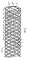
- FIG. 2shows device 100 after half of the twelve loose strand ends have been backbraided.
- one or more coupling structuresmay be coupled to strand end portions of the woven device at any desired location along the length of the device.
- the devicemay be loaded onto a mandrel before the coupling structure(s) are positioned so that the internal diameter of the device is accurately set.
- the coupling structuresOnce the coupling structures have been positioned as desired, they can be secured to the strand end portions using any suitable technique, such as laser welding (which is described in more detail below).
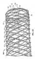
- FIG. 5depicts the two device ends 102 and 104 of a version of device 100 created through the weaving, backbraiding, and coupling structure securing techniques that produced the devices shown in FIGS. 1-4B and 6-9 , and shows that device ends 102 and 104 (device end 104 is the device end nearest the coupling structures that were used) are each defined by strand bends 40 (not all of which are labeled) that all have a substantially similar shape.
- the coupling structure nearest to a particular device endmay be spaced apart from that device end by at least one strand crossing or more.
- the right-most coupling structure 20 that is depictedis spaced apart from the depicted device end by at least three strand crossings (which are designated by a circle marked 30) taken along a line 55 that is substantially parallel to longitudinal axis 50 of device 10.
- This right-most coupling structureis spaced apart from the depicted device end by at least one device opening or more; in particular, by at least three device openings (device openings 45 have been outlined elsewhere in the figure to show that such openings (also characterizable as mesh openings) are defined by strand crossings and, in particular, four strand crossings except for the end-most rows of device openings, which are defined by only three strand crossings (thus, all the device openings of the version of device 100 shown in this figure are defined by at least three strand crossings)). Furthermore, this right-most coupling structure forms the fourth strand crossing 30 along line 55 from the depicted device end, and is positioned beneath a strand of device 10 that crosses over it.
- Each of the other coupling structures 20is likewise positioned beneath a strand of device 10 that crosses over it. Prior to the securing, the strand ends to which a given coupling structure is secured may be cut (as necessary) so as to be substantially centered beneath the strand that will pass over that coupling structure; consequently, the coupling structure will be substantially centered at the crossing it, in part, defines, as is true of the coupling structures 20 shown in FIGS. 3-4B .
- the coupling structures that are usedmay be axially aligned as are coupling structures 20 shown in FIGS. 3 , 4A , and 4B and in FIGS. 6 and 7 , or they may be spaced apart from each other axially and positioned around the circumference of the device, as are coupling structures 20 shown in FIGS. 8 and 9 .
- the cutter used to cut the strand endsmay be an Erem® cutter Model 576TX (carbide cutter) or 503ETST (oblique head carbide cutter), which are available from Cooper Hand Tools (Cooper Industries, LLC). Given the small size of the device, a microscope may be employed during the strand end cutting and coupling structure placement.
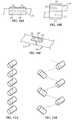
- FIGS. 10A, 10CExamples of coupling structures for joining or coupling two strand ends, which can be of different strands or the same strand, and example arrangements of strand end portions secured by them are shown in FIGS. 10A, 10C .
- FIG. 10Ashows coupling structure 20 secured to strand end portions 12 and 14 in a butt joint or butt configuration; as a result of this arrangement, strand end portions 12 and 14 are substantially aligned with each other.
- Coupling structure 20is secured to strand end portion 12 by a weld that forms a first welded region 22 and to strand end portion 14 by a weld that forms a second welded region 24.
- first welded region 22is not connected to second welded region 24 by another welded region; the two welded regions are spaced apart from each and separate.
- the two strand end portions shown in this figureare not in direct contact with each other (there is a slight gap between their ends), though in other embodiments they are in direct contact with each other.
- the version of coupling structure 20 shown in FIG. 10Ahas a passageway that exists prior to the coupling structure being secured to either of the strand end portions, and the passageway is sized to receive one device strand.
- FIG. 10Bshows coupling structure 20 secured to strand end portions 12 and 14 in lap joint or lap configuration; this configuration does not form part of the invention as claimed and also may be characterized as overlapping.
- the two strand end portionsare positioned beside each other rather than end-to-end.
- the two welded regions 22 and 24share the same characteristics as those in the FIG. 10A embodiment: they are not connected to each other by another welded region; they are spaced apart from each and separate.
- FIG. 10Bare directed to only one strand end portion, each, they could both also be applied to both strand end portions, as were the welds that produced the welded regions shown in, for example, FIG. 6 .
- the version of coupling structure 20 shown in FIG. 10Bhas a passageway that exists prior to the coupling structure being secured to either of the strand end portions, and the passageway is sized to receive two device strands.
- FIG. 10Cshows another embodiment of one of the present coupling structures, coupling structure 20', which is secured to first strand end portion 12 and to second strand end portion 14 by two welds that form first and second welded regions 22 and 24.
- Coupling structure 20'does not have a passageway; instead, it is configured as a portion of a tubular structure (e.g., as a strip with an arc, though in other embodiments the strip is flat).
- FIG. 11Ais a schematic representation showing that the coupling structures 20 for a given device can be axially aligned.
- FIG. 11Bshows they can be helically arranged, which is one way of offsetting them axially and circumferentially (such as at 60 degree intervals) from each other.
- woven stents made from nitinol wiressuch as those that include 56.0 percent nickel by weight of the total composition and titanium as the balance of the total composition
- coupling structures made from the same type of nitinolsuch as 55.8 percent nickel by weight of the total composition and titanium as the balance of the total composition
- laser weldingsuch as pulsed laser welding
- FIG. 12An example of a suitable laser welding system is shown in FIG. 12 , and includes a LASAG pulsed Nd:YAG (Neodymium:Yttrium Aluminum Garnet) "EasyWelder" laser system from the SLS 200 series (Lasag, Switzerland).
- nitinol coupling structuresFor a stent made from six nitinol wires (nickel - 56.0 percent by weight of the total composition; titanium - balance of the total composition), six nitinol coupling structures (nickel - 55.8 percent by weight of the total composition; titanium - balance of the total composition) may be used.
- the table in FIG. 13provides example inner diameter, outer diameter and length dimensions of nitinol coupling structures that can be used for a given diameter nitinol wire size of a given size of six-strand woven stent, and further provides example settings for the LASAG welding system identified above (scfh stands for cubic feet per hour under standard conditions).
- FIG. 14ADimensions for welded region 24 of a given coupling structure 20 of one of the present devices (specifically, a woven stent such as those shown in FIGS. 1-4B ) are depicted in FIG. 14A and example values for those dimensions are set forth in FIG. 14B .
- Table 2 belowprovides example values for the dimensions of a tubular coupling structure corresponding to the "Coupling Structure Code” set forth in FIG. 14B : Table 2 Coupling Structure Code Coupling Structure Inner Dia. (in./mm) Coupling Structure Outer Dia.
- routines written in industry-standard NCcan be used to program the LASAG welding system identified above for use in creating butt-coupled joints using the coupling structures described above for the various sizes of nitinol stents (formed from using the nickel-titanium mixture described above) recited before each routine:
Landscapes
- Health & Medical Sciences (AREA)
- Engineering & Computer Science (AREA)
- Biomedical Technology (AREA)
- Cardiology (AREA)
- Oral & Maxillofacial Surgery (AREA)
- Transplantation (AREA)
- Heart & Thoracic Surgery (AREA)
- Vascular Medicine (AREA)
- Life Sciences & Earth Sciences (AREA)
- Animal Behavior & Ethology (AREA)
- General Health & Medical Sciences (AREA)
- Public Health (AREA)
- Veterinary Medicine (AREA)
- Optics & Photonics (AREA)
- Physics & Mathematics (AREA)
- Textile Engineering (AREA)
- Plasma & Fusion (AREA)
- Mechanical Engineering (AREA)
- Manufacturing & Machinery (AREA)
- Pulmonology (AREA)
- Gastroenterology & Hepatology (AREA)
- Media Introduction/Drainage Providing Device (AREA)
- Prostheses (AREA)
- Ropes Or Cables (AREA)
- Superconductors And Manufacturing Methods Therefor (AREA)
- Orthopedics, Nursing, And Contraception (AREA)
- Materials For Medical Uses (AREA)
- Laser Beam Processing (AREA)
Description
- The present invention relates generally techniques and structures for securing the ends of strands, such as wires, of woven, self-expanding stents.
- Examples of devices suitable for insertion into an anatomical structure that are created from one or more strands are found in
U.S. Patent Nos. 6,007,574 ;6,419,694 ; and7,018,401 ; and in U.S. Patent Application Publication Nos.US 2005/0049682 andUS 2006/0116752 . DocumentUS 2002/147489 A1 discloses a woven, self-expanding stent having two wires made of nitinol. A same wire is bent on each of the stent ends. The ends of each wire are joined side to side by welding or by a sleeve. - Some embodiments of the present methods as disclosed in the appended claims include securing a coupling structure to a first strand end portion of a device configured for insertion into an anatomical structure; and securing the coupling structure to a second strand end portion of the device; where the first and second strand end portions are substantially aligned, the coupling structure is not a strand of the device, and the device includes one or more strands that include nickel and titanium. In some embodiments, the length of the coupling structure is less than 25, 24, 23, 22, 21, 20, 19, 18, 17, 16, 15, 14, 13, 12, 11, 10, 9, 8, 7, 6, 5, 4, 3, 2, 1, 0.9, 0.8, 0.7, 0.6, 0.5, 0.4, 0.3, 0.2, or 0.1 percent of the length of the device; this may be true for each coupling structure that is used. The coupling structure may be configured such that it has a passageway before it is secured to the first and second strand portions, and it may be placed into direct contact with the first and second strand end portions prior to the securing. The device is a stent woven from multiple strands.
- The device is self-expanding. The device may have two or more device ends (such as the two ends of a straight stent or the three ends of a bifurcated stent), and each device end may be characterized by or defined by strand bends, where the strand bends of a given device end are similar (e.g., substantially similar) in shape to at least each other and in some instances to all of the strand bends of all the device ends, such that one device end looks very similar to the other device end or device ends. The number of coupling structures that are used may correspond to the number of strands (e.g., wires) that are used to create the device, and they may be positioned in axial alignment (parallel to the longitudinal axis of the device) or they may be axially offset from each other and positioned around the circumference of the device. The securing may be accomplished by welding (e.g., laser welding) the coupling structure to the first strand end portion to create a first welded region and by welding the coupling structure to the second strand end portion to create a second welded region. The two welded regions may be separated from each and unconnected by any other welded region. The two strand end portions directly touch each other in some embodiments, and in other embodiments are not in direct contact with each other. The strand end portions are substantially aligned with each other (end-to-end).
- In some embodiments, the coupling structure is a piece of material that is separate from the first strand end portion and from the second strand end portion and, when a weld is used to accomplish the securing, is placed into direct contact with both strand end portions before the welding begins. In some embodiments, some or all of the securing steps result in a given half of a given strand being secured to either (a) only one other strand or (b) only the other half of the same strand. In some embodiments, the coupling structure is positioned beneath a strand that crosses over it. In some embodiments, all coupling structures that are used are positioned in this same fashion. In some embodiments, neither the coupling structure nor the strand end portions to which it is secured undergo a smoothing step after the securing is complete. In some embodiments where the device is woven from multiple strands such that strand crossings are created defining obtuse angles that increase when the device is axially compressed from an unconstrained state, each device opening (other than the openings that border the longitudinal passageway or passageways of the device) is defined by at least three strand crossings, where each strand crossing is defined by two crossed strand portions. In some embodiments, the coupling structure positioned nearest to a particular end of the device (a "device end") is spaced apart from all device ends (even at the portion of the coupling structure nearest the device end in question) by at least one strand crossing (in some embodiments, by at least two strand crossings; in some embodiments, by at least three strand crossings; in some embodiments, by at least four strand crossing; in some embodiments, by at least five strand crossings) in a direction (e.g., along a line) that is substantially parallel with a longitudinal axis of the device.
- Methods as disclosed in the appended claims include welding a coupling structure to a first strand end portion of a device configured for insertion into an anatomical structure; and welding the coupling structure to a second strand end portion of the device; where the coupling structure is not a strand of the device, and the device includes one or more strands that include nickel and titanium.
- Devices as disclosed in the appended claims have strands and are configured for insertion into an anatomical structure. The present devices include a coupling structure secured to two different strand end portions that are substantially aligned with each other; where the two different strand end portion includes nickel and titanium, and the coupling structure is not a strand of the device. In some embodiments, the present devices include a coupling structure welded to two different strand end portions; where the two different strand end portion includes nickel and titanium, and the coupling structure is not a strand of the device. The device is a woven, self-expanding stent.
- The number of coupling structures that are used corresponds to the number of strands (e.g., wires) the device has, and they may be positioned in axial alignment (parallel to the longitudinal axis of the woven device) or they may be axially offset from each other and positioned around the circumference of the device. The strand end portions in each pair that are secured with (e.g., welded to) a given coupling structure are aligned with each other. In some embodiments, the length of the coupling structure is less than 25, 24, 23, 22, 21, 20, 19, 18, 17, 16, 15, 14, 13, 12, 11, 10, 9, 8, 7, 6, 5, 4, 3, 2, 1, 0.9, 0.8, 0.7, 0.6, 0.5, 0.4, 0.3, 0.2, or 0.1 percent of the length of the device; this may be true for each coupling structure that is used. The coupling structure may be configured such that it has a passageway before it is secured to the first and second strand portions, and it may be placed into direct contact with the first and second strand end portions prior to being secured (e.g., welded). The device is a stent woven from multiple strands. The device is self-expanding. The device may have two or more device ends (such as the two ends of a straight stent or the three ends of a bifurcated stent), and each device end may be characterized by or defined by strand bends, where the strand bends of a given device end are similar (e.g., substantially similar) in shape to at least each other and in some instances to all of the strand bends of all the device ends, such that one device end looks very similar to the other device end or device ends. The number of coupling structures that are used may correspond to the number of strands (e.g., wires) that are used to create the device, and they may be positioned in axial alignment (parallel to the longitudinal axis of the device) or they may be axially offset from each other and positioned around the circumference of the device. The coupling structure may be secured to the first strand end portion by a weld that forms a first welded region, the coupling structure is secured to the second strand end portion by a weld that forms a second welded region, and the first and second welded regions are not directly connected to each other by another welded region. The two welded regions may be separated from each and unconnected by any other welded region. The two strand end portions directly touch each other in some embodiments, and in other embodiments are not in direct contact with each other. In some embodiments, the coupling structure is a piece of material that is separate from the first strand end portion and from the second strand end portion and, when a weld is used to secure the coupling structure to those strand end portions, is placed into direct contact with both strand end portions before the welding begins. In some embodiments, a given half of a given strand of the device is secured to either (a) only one other strand or (b) only the other half of the same strand. In some embodiments, the coupling structure is positioned beneath a strand that crosses over it. In some embodiments, all coupling structures that are used are positioned in this same fashion. In some embodiments, neither the coupling structure nor the strand end portions to which it is secured require smoothing after being secured. In some embodiments where the device is woven from multiple strands such that strand crossings are created defining obtuse angles that increase when the device is axially compressed from an unconstrained state, each device opening (other than the openings that border the longitudinal passageway or passageways of the device) is defined by at least three strand crossings, where each strand crossing is defined by two crossed strand portions. In some embodiments, the coupling structure positioned nearest to a particular end of the device (a "device end") is spaced apart from all device ends (even at the portion of the coupling structure nearest the device end in question) by at least one strand crossing (in some embodiments, by at least two strand crossings; in some embodiments, by at least three strand crossings; in some embodiments, by at least four strand crossing; in some embodiments, by at least five strand crossings) in a direction (e.g., along a line) that is substantially parallel with a longitudinal axis of the device.
- Any embodiment of any of the present methods and device may consist of or consist essentially of-rather than comprise/include/contain/have-the described steps and/or features.
- Details associated with these embodiments and others are provided below.
- The following drawings illustrate by way of example and not limitation. Identical reference numerals do not necessarily indicate an identical structure. Rather, the same reference numeral may be used to indicate a similar feature or a feature with similar functionality. Not every feature of each embodiment is labeled in every figure in which that embodiment appears, in order to keep the figures clear.
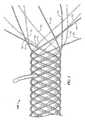
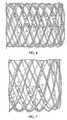
FIG. 1 shows an example of a portion of a device that is being configured for insertion into an anatomical structure, and at a stage of creation where free strand ends are positioned at one end of the device. There is a hook depicted in the top, central portion of the figure that is holding the device to an underlying surface. The hook is not part of the device.FIG. 2 shows an example of a portion of a device that is being configured for insertion into an anatomical structure, and at a stage of creation where half the free strand ends have been backbraided and the other half remain at one end of the device.FIG. 3 shows an example of a portion of a device after the weaving reflected inFIG. 1 and the backbraiding reflected inFIG. 2 and that includes coupling structures equal in number to the strands used to create it. Specifically, one coupling structure has been laser welded to each of six different pairs of substantially-aligned strand end portions of the device (for a total of six coupling structures).FIGS. 4A and4B show examples of portions of other devices similar to the one shown inFIG. 3 .FIG. 5 shows the configuration of the device ends (and the similarity of the strand bends that define them) of a device similar to the one shown inFIGS. 3 and4 .FIG. 6 shows an example of a portion of a device having coupling structures that are axially-aligned and that secure two strand end portions each in overlapping relationship , this embodiment does not form part of the invention as claimed.FIG. 7 shows an example of a portion of a device having coupling structures that are axially-aligned and that secure two substantially-aligned strand end portions each.FIG. 8 shows an example of a portion of a device similar to the one shown inFIG. 6 , except that adjacent coupling structures are spaced apart from each other around the circumference of the device. Two of the coupling structures that are farthest from the viewer are labeled.FIG. 9 shows an example of a portion of a device similar to the one shown inFIG. 7 , except that adjacent coupling structures are spaced apart from each other around the circumference of the device.FIG. 10A depicts one coupling structure secured to two strand end portions that are substantially aligned.FIG. 10B depicts one coupling structure secured to two strand end portions that overlap with each other, this embodiment does not form part of the invention as claimed.FIG. 10C depicts another embodiment of a coupling structure that is secured to two strand end portions that are substantially aligned.FIGS. 11A and 11B are schematic representations showing different example arrangements of coupling structures for a device such as a woven stent.FIG. 12 shows an example of a laser welding system that can be used to create the devices shown inFIGS. 2-9 .FIG. 13 is a table providing example inner diameter, outer diameter and length dimensions of nitinol coupling structures that can be used for a given diameter nitinol wire size of a given size of six-strand woven stent, and further provides example settings for the LASAG welding system identified below (scfh stands for cubic feet per hour under standard conditions).FIG. 14A is a detail view showing certain dimensions of a welded region created by a weld that secures the depicted coupling structure to the depicted strand.FIG. 14B is a table containing example values for the dimensions depicted inFIG. 14A and other aspects of a stent created according to the present methods.- The terms "comprise" (and any form of comprise, such as "comprises" and "comprising"), "have" (and any form of have, such as "has" and "having"), "contain" (and any form of contain, such as "contains" and "containing"), and "include" (and any form of include, such as "includes" and "including") are open-ended linking verbs. As a result, a device or method that "comprises," "has," "contains," or "includes" one or more elements possesses those one or more elements, but is not limited to possessing only those one or more elements or steps. Likewise, an element of a device or a step of a method that "comprises," "has," "contains," or "includes" one or more features possesses those one or more features, but is not limited to possessing only those one or more features. Furthermore, a structure that is configured in a certain way must be configured in at least that way, but also may be configured in a way or ways that are not specified.
- Any embodiment of any of the present methods and devices may consist of or consist essentially of-rather than comprise/include/contain/have-the described steps and/or features, which fall within the scope of the appended claims.
- Thus, and by way of example, while some embodiments of the present methods comprise welding a coupling structure to a first strand end portion of a device configured for insertion into an anatomical structure; and welding the coupling structure to a second strand end portion of the device; where the coupling structure is not a strand of the device, and the device includes one or more strands that include nickel and titanium, other embodiments consist essentially of or consist of welding a coupling structure to a first strand end portion of a device configured for insertion into an anatomical structure; and welding the coupling structure to a second strand end portion of the device; where the coupling structure is not a strand of the device, and the device includes one or more strands that include nickel and titanium.
- The terms "a" and "an" are defined as one or more than one unless this disclosure explicitly requires otherwise. The terms "substantially" and "about" are defined as at least close to (and include) a given value or state (preferably within 10% of, more preferably within 1% of, and most preferably within 0.1% of).
- The present methods may be used to secure two unsecured strand ends of a device configured for insertion into an anatomical structure. The initial process used to create the device involves weaving - such as the weaving techniques disclosed in
U.S. Patent Nos. 6,792,979 and7,048,014 , one suitable braiding machine that may be used is theSteeger 24 Carrier Horizontal Fine Wire Carrier Braider HS 140-24-IH manufactured by Steeger USA (Spartanburg, South Carolina). The device is created from strands, and it may have a variety of configurations, such as stent (e.g., one with two ends or a multi-legged stent with more than two ends).
The strand ends may be secured with a coupling structure that includes a passageway (such as a small tube) into which the strand ends can be inserted from opposite ends and that is welded (e.g., laser welded) to the strand end portions inserted into it. However, the coupling structure need not encompass the strand ends, as a small tube does. Instead, in other embodiments, the coupling structure could comprise a flat strip to which the strand ends are coupled, or a strip that is contoured, such as a portion of a small tube. Furthermore, though laser welding is discussed below as a preferred joining technique, other techniques may be used, including (but not limited to) electron beam welding, resistance welding, tungsten inert gas welding, metal inert gas welding, crimping, soldering, braising, and gluing. - The coupling structure may be made from the same materials as the strand end portions to which it is coupled (e.g., a nickel-titanium coupling structure may be used to couple two nickel-titanium strand end portions together), or it may be made from a different material or materials (e.g., a stainless steel coupling structure may be used to couple two nickel-titanium strand end portions together).
- In embodiments which are woven from nickel-titanium wires (nickel - 56.0 percent by weight of the total composition; titanium - balance of the total composition), and the initial weaving is complete, the device (with the mandrel on which it was formed, if desired) can be heat treated according to the information in Table 1 below:
Table 1 Stent Diameter (mm) Furnace Temperature Setting (°C) Heat Treatment Time (minutes) 4.0 525 5 5.0 535 5 6.0 510 10 7.0 520 10 8.0 510 13 9.0 520 13 10.0 530 13 FIG. 1 shows an example of a device (device 100) that has one or more strands and is configured for insertion into an anatomical structure.Device 100, which is a stent, was created woven according to techniques disclosed inU.S. Patent No. 7,018,401 from six strands (wires) that possess twelve strand halves 10. There are no free strand ends at the device end ofdevice 100 that is not shown. Each half strand was secured (see, e.g.,FIG. 3 ) to only one other half strand (which either belonged to the same or a different strand). - After this heat treatment, the device can be immediately quenched in deionized water until cool. Next, the free strand ends of the device can be backbraided as desired and then baked according to the information in the same table and immediately quenched in deionized water until cool.
FIG. 2 showsdevice 100 after half of the twelve loose strand ends have been backbraided. - Next, one or more coupling structures (e.g., coupling structures that include nickel and titanium, such as 55.8 percent nickel by weight of the total composition and titanium as the balance of the total composition) may be coupled to strand end portions of the woven device at any desired location along the length of the device. The device may be loaded onto a mandrel before the coupling structure(s) are positioned so that the internal diameter of the device is accurately set. Once the coupling structures have been positioned as desired, they can be secured to the strand end portions using any suitable technique, such as laser welding (which is described in more detail below).
FIGS. 3-4B show examples ofdevice 100 after couplingstructures 20 have each been placed into contact with a pair of strand end portions and then welded to those strand end portions using laser welding as described below.FIG. 5 , depicts the two device ends 102 and 104 of a version ofdevice 100 created through the weaving, backbraiding, and coupling structure securing techniques that produced the devices shown inFIGS. 1-4B and6-9 , and shows that device ends 102 and 104 (device end 104 is the device end nearest the coupling structures that were used) are each defined by strand bends 40 (not all of which are labeled) that all have a substantially similar shape. - As shown in
FIGS. 3 and4A , in some embodiments, the coupling structure nearest to a particular device end (e.g., theright-most coupling structure 20 shown in these figures) may be spaced apart from that device end by at least one strand crossing or more. In the embodiment shown in these figures, theright-most coupling structure 20 that is depicted is spaced apart from the depicted device end by at least three strand crossings (which are designated by a circle marked 30) taken along aline 55 that is substantially parallel tolongitudinal axis 50 ofdevice 10. This right-most coupling structure is spaced apart from the depicted device end by at least one device opening or more; in particular, by at least three device openings (device openings 45 have been outlined elsewhere in the figure to show that such openings (also characterizable as mesh openings) are defined by strand crossings and, in particular, four strand crossings except for the end-most rows of device openings, which are defined by only three strand crossings (thus, all the device openings of the version ofdevice 100 shown in this figure are defined by at least three strand crossings)). Furthermore, this right-most coupling structure forms the fourth strand crossing 30 alongline 55 from the depicted device end, and is positioned beneath a strand ofdevice 10 that crosses over it. Each of theother coupling structures 20 is likewise positioned beneath a strand ofdevice 10 that crosses over it. Prior to the securing, the strand ends to which a given coupling structure is secured may be cut (as necessary) so as to be substantially centered beneath the strand that will pass over that coupling structure; consequently, the coupling structure will be substantially centered at the crossing it, in part, defines, as is true of thecoupling structures 20 shown inFIGS. 3-4B . - The coupling structures that are used (for stents, the number of coupling structures will equal the number of strands) may be axially aligned as are coupling
structures 20 shown inFIGS. 3 ,4A , and4B and inFIGS. 6 and 7 , or they may be spaced apart from each other axially and positioned around the circumference of the device, as are couplingstructures 20 shown inFIGS. 8 and 9 . The cutter used to cut the strand ends may be an Erem® cutter Model 576TX (carbide cutter) or 503ETST (oblique head carbide cutter), which are available from Cooper Hand Tools (Cooper Industries, LLC). Given the small size of the device, a microscope may be employed during the strand end cutting and coupling structure placement. - Examples of coupling structures for joining or coupling two strand ends, which can be of different strands or the same strand, and example arrangements of strand end portions secured by them are shown in
FIGS. 10A, 10C . FIG. 10A showscoupling structure 20 secured to strandend portions strand end portions Coupling structure 20 is secured to strandend portion 12 by a weld that forms a first weldedregion 22 and to strandend portion 14 by a weld that forms a second weldedregion 24. As shown, first weldedregion 22 is not connected to second weldedregion 24 by another welded region; the two welded regions are spaced apart from each and separate. Furthermore, the two strand end portions shown in this figure are not in direct contact with each other (there is a slight gap between their ends), though in other embodiments they are in direct contact with each other. The version ofcoupling structure 20 shown inFIG. 10A has a passageway that exists prior to the coupling structure being secured to either of the strand end portions, and the passageway is sized to receive one device strand.FIG. 10B showscoupling structure 20 secured to strandend portions regions FIG. 10A embodiment: they are not connected to each other by another welded region; they are spaced apart from each and separate. Although the welds that produced the two welded regions illustrated schematically inFIG. 10B are directed to only one strand end portion, each, they could both also be applied to both strand end portions, as were the welds that produced the welded regions shown in, for example,FIG. 6 . The version ofcoupling structure 20 shown inFIG. 10B has a passageway that exists prior to the coupling structure being secured to either of the strand end portions, and the passageway is sized to receive two device strands.FIG. 10C shows another embodiment of one of the present coupling structures, coupling structure 20', which is secured to firststrand end portion 12 and to secondstrand end portion 14 by two welds that form first and second weldedregions FIG. 11A is a schematic representation showing that thecoupling structures 20 for a given device can be axially aligned.FIG. 11B shows they can be helically arranged, which is one way of offsetting them axially and circumferentially (such as at 60 degree intervals) from each other.- For woven stents made from nitinol wires (such as those that include 56.0 percent nickel by weight of the total composition and titanium as the balance of the total composition), coupling structures made from the same type of nitinol (such as 55.8 percent nickel by weight of the total composition and titanium as the balance of the total composition) can be used to couple the ends of different strands using laser welding, such as pulsed laser welding. An example of a suitable laser welding system is shown in
FIG. 12 , and includes a LASAG pulsed Nd:YAG (Neodymium:Yttrium Aluminum Garnet) "EasyWelder" laser system from theSLS 200 series (Lasag, Switzerland). - For a stent made from six nitinol wires (nickel - 56.0 percent by weight of the total composition; titanium - balance of the total composition), six nitinol coupling structures (nickel - 55.8 percent by weight of the total composition; titanium - balance of the total composition) may be used. The table in
FIG. 13 provides example inner diameter, outer diameter and length dimensions of nitinol coupling structures that can be used for a given diameter nitinol wire size of a given size of six-strand woven stent, and further provides example settings for the LASAG welding system identified above (scfh stands for cubic feet per hour under standard conditions). - The following is a brief description of how coupling structures are secured to the pairs of wire end portions of a heat-treated (according to the technique described above), six-wire woven nitinol stent through a process that is at least partially automated (and in other embodiments fully automated) using the LASAG welding system described above:
- the stent has been partially braided back (e.g., by hand), meaning that six of the 12 wire ends are braided back into the stent;
- starting at any suitable wire crossing (e.g., the fourth or fifth wire crossing from the end that has been braided back), the wire ends are cut as described above such that the ends of the wires come into contact under the crossing wire;
- the coupling structures are loaded onto the wire ends and centered about the crossing wire while on a mandrel so that the internal diameter of the stent is accurately set;
- the coupling region of the stent is secured to the mandrel with a spring loaded clip to prevent relative motion between the stent and mandrel, to accurately set the internal diameter of the stent, and to maintain the proper placement of the wire end portions within the coupling structures;
- the mandrel mounted and secured stent is then placed in the laser welding system and the first coupling structure is aligned with the horizontal crosshair on the view screen of the system;
- the welding program for the size of stent to be welded (examples provided below) is invoked; and
- the operator is prompted to align the crosshairs with the upper-left corner of the coupling. Once aligned, the operator presses the start button and the left weld bead is created. The system then moves and prompts the operator to align the crosshairs to the upper-right corner. Once aligned, the operator presses the start button and the right weld bead is created. The system then moves to the upper-left corner of the second coupling and the process is repeated. This continues until all 12 welds are completed.
- Dimensions for welded
region 24 of a givencoupling structure 20 of one of the present devices (specifically, a woven stent such as those shown inFIGS. 1-4B ) are depicted inFIG. 14A and example values for those dimensions are set forth inFIG. 14B . Table 2 below provides example values for the dimensions of a tubular coupling structure corresponding to the "Coupling Structure Code" set forth inFIG. 14B :Table 2 Coupling Structure Code Coupling Structure Inner Dia. (in./mm) Coupling Structure Outer Dia. (in./mm) Coupling Structure Length (in./mm) -01 0.0070/0.1778 0.0100/0.2540 0.070/1.778 -02 0.0070/0.1778 0.0100/0.2540 0.080/2.032 -03 0.0075/0.1905 0.0105/0.2667 0.100/2.540 -04 0.0085/0.2159 0.0120/0.3048 0.120/3.048 -05 0.0085/0.2159 0.0120/0.3048 0.150/3.810 FIG. 14B are as follows: X. = ±1; .X = ±.5; .XX = ±.25; .XXX = ±.125. Unless otherwise set forth, the tolerances for the values in Table 2 are as follows: .X = ±.030; .XX = ±.010; .XXX = ±.005. - Thus, taking the first row of
FIG. 14B as an example, a given stent with an internal diameter of 4.0 mm and a length of 40 mm made from nitinol wires (such as those described above) having 0.006 inch (0.152mm) diameters could be made with tubular coupling structures (code -01) that each have an internal diameter of .0070 inches (0.1778mm), an outer diameter of 0.0100 inches (0.2540mm), and a length of 0.070 inches (1.778mm), with dimensions A, B, and C of the welded region produced by a laser weld that secures that coupling structure to one of the specified wires having the dimensions of A=0.010 inches (0.254mm), B=0.005 inches (0.127mm), and C=0.010 inches (0.254mm). - The following routines written in industry-standard NC (numerical code) can be used to program the LASAG welding system identified above for use in creating butt-coupled joints using the coupling structures described above for the various sizes of nitinol stents (formed from using the nickel-titanium mixture described above) recited before each routine:
- ;4mm Stent Welding Program
- M61
- ;Laser Remote Control
- ; Welding Parameters
- C101 Q10
- ;
FREQUENCY 10 HZ - C102 Q0.25
- ;PULSE LENGTH 0.25ms
- C108 Q200
- ;Peak Power 200 W
- C111 Q120
- ;A-Scale 120
- M51
- ;MONITOR LASER OK
- ;Move Laser to common work place
- G90
- ; Absolute Coordinate
- F50
- ; Feed Rate
- X3.93 Y-4.6
- ; Locate fixture and part
- Z-2.656
- ; Adjust Focus
- ; Weld six couplings
- M26 H152
- ; Reset Door
- M98 P2
- ; Goto Subroutine 1 - 1st Coupling
- F4
- ; Fast Feed for inter move
- X-.040 Y.037
- ; Move back to relative 0,0
- M98 P2
- ; Goto Subroutine 1 - 2nd Coupling
- F4
- ; Fast Feed for inter move
- X-.040 Y.037
- ; Move back to relative 0,0
- M98 P2
- ; Goto Subroutine 1 - 3rd Coupling
- F4
- ; Fast Feed for inter move
- X-.040 Y.037
- ; Move back to relative 0,0
- M98 P2
- ; Goto Subroutine 1 - 4th Coupling
- F4
- ; Fast Feed for inter move
- X-.040 Y.037
- ; Move back to relative 0,0
- M98 P2
- ; Goto Subroutine 1 - 5th Coupling
- F4
- ; Fast Feed for inter move
- X-.040 Y.037
- ; Move back to relative 0,0
- M98 P2
- ; Goto Subroutine 1 - 6th Coupling
- ;Go Back to common work place
- G90
- ; Absolute Coordinate
- F50
- ; Feed Rate
- X3.93 Y-4.6
- ; Locate fixture and part
- M25 H152
- ; Open Door
- M02
- ; End of NC
- ; Coupling Weld Subroutine
- 02
- ; Welding Routine
- F1
- ; Feed Rate
- G05Q1
- ; Jog with Pause / Move to Upper Left Corner
- G91
- ; Incremental Coordinates
- M8
- ; Gas On
- G4F.5
- ; Dwell for .5 seconds
- X0.008 Y-.004
- ; Offset from corner of coupling
- M71
- ; Laser Processing with Sync. feed
- X0.015
- ; Weld left bead = .015:
- M70
- ; Stop laser processing
- X0.058 Y.0045
- ; Index to Right Upper Corner
- G05Q1
- ; Jog with Pause / Adjust to Upper Right Corner
- X-0.008 Y-.004
- ; Offset from right corner of coupling
- M71
- ; Laser Processing with Sync. feed
- X-0.015
- ; Weld bead = .015:
- M70
- ; Stop laser processing
- M9
- ; Gas off
- M99
- ; Return
- ;5mm Stent Welding Program
- M61
- ;Laser Remote Control
- ; Welding Parameters
- C101 Q10
- ;
FREQUENCY 10 HZ - C102 Q0.25
- ;PULSE LENGTH 0.25ms
- C108 Q200
- ;Peak Power 200 W
- C111 Q120
- ; A-Scale 120
- M51
- ;MONITOR LASER OK
- ; Move to common work place
- G90
- ; Absolute Coordinate
- F50
- ; Feed Rate
- X3.93 Y-4.6
- ; Locate fixture and part
- Z-2.656
- ; Adjust Focus
- ; Weld six couplings
- M26 H152
- ; Reset Door
- M98 P2
- ; Goto Subroutine 1 - 1st Coupling
- F4
- ; Fast Feed for inter move
- X-.040 Y.041
- ; Move back to relative 0,0
- M98 P2
- ; Goto Subroutine 1 - 2nd Coupling
- F4
- ; Fast Feed for inter move
- X-.040 Y.041
- ; Move back to relative 0,0
- M98 P2
- ; Goto Subroutine 1 - 3rd Coupling
- F4
- ; Fast Feed for inter move
- X-.040 Y.041
- ; Move back to relative 0,0
- M98 P2
- ; Goto Subroutine 1 - 4th Coupling
- F4
- ; Fast Feed for inter move
- X-.040 Y.041
- ; Move back to relative 0,0
- M98 P2
- ; Goto Subroutine 1 - 5th Coupling
- F4
- ; Fast Feed for inter move
- X-.040 Y.041
- ; Move back to relative 0,0
- M98 P2
- ; Goto Subroutine 1 - 6th Coupling
- ;Go Back to common work place
- G90
- ; Absolute Coordinate
- F50
- ; Feed Rate
- X3.93 Y-4.6 ;
- Locate fixture and part
- M25 H152
- ; Open Door
- M02
- ; End of NC
- ; Coupling Weld Subroutine
- 02
- ; Welding Routine
- F1
- ; Feed Rate
- G05Q1
- ; Jog with Pause / Move to Upper Left Corner
- G91
- ; Incremental Coordinates
- M8
- ; Gas On
- G4F.5
- ; Dwell for .5 seconds
- X0.010 Y-.004
- ; Offset from corner of coupling
- M71
- ; Laser Processing with Sync. feed
- X0.015
- ; Weld left bead = .015:
- M70
- ; Stop laser processing
- X0.055 Y.0045
- ; Index to Right Upper Corner
- G05Q1
- ; Jog with Pause / Adjust to Upper Right Corner
- X-0.010 Y-.004
- ; Offset from right corner of coupling
- M71
- ; Laser Processing with Sync. feed
- X-0.015
- ; Weld bead = .015:
- M70
- ; Stop laser processing
- M9
- ; Gas off
- M99
- ; Return
- ;6mm Stent Welding Program
- M61
- ;Laser Remote Control
- ; Welding Parameters
- C101 Q10
- ;
FREQUENCY 10 HZ - C102 Q0.3
- ;PULSE LENGTH 0.3ms
- C108 Q300
- ;Peak Power 200 W
- C111 Q100
- ;A-Scale 100
- M51
- ;MONITOR LASER OK
- ; Move to common work place
- G90
- ; Absolute Coordinate
- F50
- ; Feed Rate
- X3.93 Y-4.6
- ; Locate fixture and part
- Z-2.6716
- ; Adjust Focus
- ; Weld six couplings
- M26 H152
- ; Reset Door
- M98 P2
- ; Goto Subroutine 1 - 1st Coupling
- F4
- ; Fast Feed for inter move
- X-.060 Y.045
- ; Move back to relative 0,0
- M98 P2
- ; Goto Subroutine 1 - 2nd Coupling
- F4
- ; Fast Feed for inter move
- X-.060 Y.045
- ; Move back to relative 0,0
- M98 P2
- ; Goto Subroutine 1 - 3rd Coupling
- F4
- ; Fast Feed for inter move
- X-.060 Y.045
- ; Move back to relative 0,0
- M98 P2
- ; Goto Subroutine 1 - 4th Coupling
- F4
- ; Fast Feed for inter move
- X-.060 Y.045
- ; Move back to relative 0,0
- M98 P2
- ; Goto Subroutine 1 - 5th Coupling
- F4
- ; Fast Feed for inter move
- X-.060 Y.045
- ; Move back to relative 0,0
- M98 P2
- ; Goto Subroutine 1 - 6th Coupling
- ; Go Back to Common work place
- G90
- ; Absolute Coordinate
- F50
- ; Feed Rate
- X3.93 Y-4.6
- ; Locate fixture and part
- M25 H152
- ; Open Door
- M02
- ; End of NC
- ; Coupling Weld Subroutine
- 02
- ; Welding Routine
- F1
- ; Feed Rate
- G05Q1
- ; Jog with Pause / Move to Upper Left Corner
- G91
- ; Incremental Coordinates
- M8
- ; Gas On
- G4F.5
- ; Dwell for .5 seconds
- X0.010 Y-.005
- ; Offset from corner of coupling
- M71
- ; Laser Processing with Sync. feed
- X0.015
- ; Weld left bead = .015:
- M70
- ; Stop laser processing
- X0.075 Y.005
- ; Index to Right Upper Corner
- G05Q1
- ; Jog with Pause / Adjust to Upper Right Corner
- X-0.010 Y-.005
- ; Offset from right corner of coupling
- M71
- ; Laser Processing with Sync. feed
- X-0.015
- ; Weld bead = .015:
- M70
- ; Stop laser processing
- M9
- ; Gas off
- M99
- ; Return
- ;7mm Stent Welding Program
- M61
- ;Laser Remote Control
- ; Welding Parameters
- C101 Q10
- ;
FREQUENCY 10 HZ - C102 Q0.3
- ;PULSE LENGTH 0.3ms
- C108 Q300
- ;Peak Power 200 W
- C111 Q100
- ;A-Scale 100
- M51
- ;MONITOR LASER OK
- ; Move to common work place
- G90
- ; Absolute Coordinate
- F50
- ; Feed Rate
- X3.93 Y-4.6
- ; Locate fixture and part
- Z-2.6716
- ; Adjust Focus
- ; Weld six couplings
- M26 H152
- ; Reset Door
- M98 P2
- ; Goto Subroutine 1 - 1st Coupling
- F4
- ; Fast Feed for inter move
- X-.060 Y.049
- ; Move back to relative 0,0
- M98 P2
- ; Goto Subroutine 1 - 2nd Coupling
- F4
- ; Fast Feed for inter move
- X-.060 Y.049
- ; Move back to relative 0,0
- M98 P2
- ; Goto Subroutine 1 - 3rd Coupling
- F4
- ; Fast Feed for inter move
- X-.060 Y.049
- ; Move back to relative 0,0
- M98 P2
- ; Goto Subroutine 1 - 4th Coupling
- F4
- ; Fast Feed for inter move
- X-.060 Y.049
- ; Move back to relative 0,0
- M98 P2
- ; Goto Subroutine 1 - 5th Coupling
- F4
- ; Fast Feed for inter move
- X-.060 Y.049
- ; Move back to relative 0,0
- M98 P2
- ; Goto Subroutine 1 - 6th Coupling
- ; Go Back to Common Work Place
- G90
- ; Absolute Coordinate
- F50
- ; Feed Rate
- X3.93 Y-4.6
- ; Locate fixture and part
- M25 H152
- ; Open Door
- M02
- ; End of NC
- ; Coupling Weld Subroutine
- 02
- ; Welding Routine
- F1
- ; Feed Rate
- G05Q1
- ; Jog with Pause / Move to Upper Left Corner
- G91
- ; Incremental Coordinates
- M8
- ; Gas On
- G4F.5
- ; Dwell for .5 seconds
- X0.010 Y-.005
- ; Offset from corner of coupling
- M71
- ; Laser Processing with Sync. feed
- X0.015
- ; Weld left bead = .015:
- M70
- ; Stop laser processing
- X0.075 Y.005
- ; Index to Right Upper Corner
- G05Q1
- ; Jog with Pause / Adjust to Upper Right Corner
- X-0.010 Y-.005
- ; Offset from right corner of coupling
- M71
- ; Laser Processing with Sync. feed
- X-0.015
- ; Weld bead = .015:
- M70
- ; Stop laser processing
- M9
- ; Gas off
- M99
- ; Return
- ;8mm Stent Welding Program
- M61
- ;Laser Remote Control
- ; Welding Parameters
- C101 Q10
- ;
FREQUENCY 10 HZ - C102 Q0.3
- ;PULSE LENGTH 0.3ms
- C108 Q300
- ;Peak Power 200 W
- C111 Q100
- ; A-Scale 100
- M51
- ;MONITOR LASER OK
- ; Move to common work place
- G90
- ; Absolute Coordinate
- F50
- ; Feed Rate
- X3.93 Y-4.6
- ; Locate fixture and part
- Z-2.6544
- ; Adjust Focus
- ; Weld six Couplings
- M26 H152
- ; Reset Door
- M98 P2
- ; Goto Subroutine 1 - 1st Coupling
- F4
- ; Fast Feed for inter move
- X-.067 Y.053
- ; Move back to relative 0,0
- M98 P2
- ; Goto Subroutine 1 - 2nd Coupling
- F4
- ; Fast Feed for inter move
- X-.067 Y.053
- ; Move back to relative 0,0
- M98 P2
- ; Goto Subroutine 1 - 3rd Coupling
- F4
- ; Fast Feed for inter move
- X-.067 Y.053
- ; Move back to relative 0,0
- M98 P2
- ; Goto Subroutine 1 - 4th Coupling
- F4
- ; Fast Feed for inter move
- X-.067 Y.053
- ; Move back to relative 0,0
- M98 P2
- ; Goto Subroutine 1 - 5th Coupling
- F4
- ; Fast Feed for inter move
- X-.067 Y.053
- ; Move back to relative 0,0
- M98 P2
- ; Goto Subroutine 1 - 6th Coupling
- ; Go Back to Common Work Place
- G90
- ; Absolute Coordinate
- F50
- ; Feed Rate
- X3.93 Y-4.6
- ; Locate fixture and part
- M25 H152
- ; Open Door
- M02
- ; End of NC
- ; Coupling Weld Subroutine
- O2
- ; Welding Routine
- F1
- ; Feed Rate
- G05Q1
- ; Jog with Pause / Move to Upper Left Corner
- G91
- ; Incremental Coordinates
- M8
- ; Gas On
- G4F.5
- ; Dwell for .5 seconds
- X0.010 Y-.006
- ; Offset from corner of coupling
- M71
- ; Laser Processing with Sync. feed
- X0.015
- ; Weld left bead = .015:
- M70
- ; Stop laser processing
- X0.095 Y.006
- ; Index to Right Upper Corner
- G05Q1
- ; Jog with Pause / Adjust to Upper Right Corner
- X-0.010 Y-.006
- ; Offset from right corner of coupling
- M71
- ; Laser Processing with Sync. feed
- X-0.015
- ; Weld bead = .015:
- M70
- ; Stop laser processing
- M9
- ; Gas off
- M99
- ; Return
- ;9mm Stent Welding Program
- M61
- ;Laser Remote Control
- ; Welding Parameters
- C101 Q10
- ;
FREQUENCY 10 HZ - C102 Q0.3
- ;PULSE LENGTH 0.3ms
- C108 Q300
- ;Peak Power 200 W
- C111 Q100
- ; A-Scale 100
- M51
- ;MONITOR LASER OK
- ; Move to common work place
- G90
- ; Absolute Coordinate
- F50
- ; Feed Rate
- X3.93 Y-4.6
- ; Locate fixture and part
- Z-2.6716
- ; Adjust Focus
- ; Weld six Couplings
- M26 H152
- ; Reset Door
- M98 P2
- ; Goto Subroutine 1 - 1st Coupling
- F4
- ; Fast Feed for inter move
- X-.067 Y.057
- ; Move back to relative 0,0
- M98 P2
- ; Goto Subroutine 1 - 2nd Coupling
- F4
- ; Fast Feed for inter move
- X-.067 Y.057
- ; Move back to relative 0,0
- M98 P2
- ; Goto Subroutine 1 - 3rd Coupling
- F4
- ; Fast Feed for inter move
- X-.067 Y.057
- ; Move back to relative 0,0
- M98 P2
- ; Goto Subroutine 1 - 4th Coupling
- F4
- ; Fast Feed for inter move
- X-.067 Y.057
- ; Move back to relative 0,0
- M98 P2
- ; Goto Subroutine 1 - 5th Coupling
- F4
- ; Fast Feed for inter move
- X-.067 Y.057
- ; Move back to relative 0,0
- M98 P2
- ; Goto Subroutine 1 - 6th Coupling
- ; Go Back to Common Work Place
- G90
- ; Absolute Coordinate
- F50
- ; Feed Rate
- X3.93 Y-4.6
- ; Locate fixture and part
- M25 H152
- ; Open Door
- M02
- ; End of NC
- ; Coupling Weld Subroutine
- 02
- ; Welding Routine
- F1
- ; Feed Rate
- G05Q1
- ; Jog with Pause / Move to Upper Left Corner
- G91
- ; Incremental Coordinates
- M8
- ; Gas On
- G4F.5
- ; Dwell for .5 seconds
- X0.010 Y-.006
- ; Offset from corner of coupling
- M71
- ; Laser Processing with Sync. feed
- X0.015
- ; Weld left bead = .015:
- M70
- ; Stop laser processing
- X0.095 Y.006
- ; Index to Right Upper Corner
- G05Q1
- ; Jog with Pause / Adjust to Upper Right Corner
- X-0.010 Y-.006
- ; Offset from right corner of coupling
- M71
- ; Laser Processing with Sync. feed
- X-0.015
- ; Weld bead = .015:
- M70
- ; Stop laser processing
- M9
- ; Gas off
- M99
- ; Return
- ;10mm Stent Welding Program
- M61
- ;Laser Remote Control
- ; Welding Parameters
- C101 Q10
- ;
FREQUENCY 10 HZ - C102 Q0.3
- ;PULSE LENGTH 0.3ms
- C108 Q300
- ;Peak Power 200 W
- C111 Q100
- ; A-Scale 100
- M51
- ;MONITOR LASER OK
- ; Move to common work place
- G90
- ; Absolute Coordinate
- F50
- ; Feed Rate
- X3.93 Y-4.6
- ; Locate fixture and part
- Z-2.6716
- ; Adjust Focus
- ; Weld six Couplings
- M26 H152
- ; Reset Door
- M98 P2
- ; Goto Subroutine 1 - 1st Coupling
- F4
- ; Fast Feed for inter move
- X-.067 Y.061
- ; Move back to relative 0,0
- M98 P2
- ; Goto Subroutine 1 - 2nd Coupling
- F4
- ; Fast Feed for inter move
- X-.067 Y.061
- ; Move back to relative 0,0
- M98 P2
- ; Goto Subroutine 1 - 3rd Coupling
- F4
- ; Fast Feed for inter move
- X-.067 Y.061
- ; Move back to relative 0,0
- M98 P2
- ; Goto Subroutine 1 - 4th Coupling
- F4
- ; Fast Feed for inter move
- X-.067 Y.061
- ; Move back to relative 0,0
- M98 P2
- ; Goto Subroutine 1 - 5th Coupling
- F4
- ; Fast Feed for inter move
- X-.067 Y.061
- ; Move back to relative 0,0
- M98 P2
- ; Goto Subroutine 1 - 6th Coupling
- ; Go Back to Common Work Place
- G90
- ; Absolute Coordinate
- F50
- ; Feed Rate
- X3.93 Y-4.6
- ; Locate fixture and part
- M25 H152
- ; Open Door
- M02
- ; End of NC
- ; Coupling Weld Subroutine
- 02
- ; Welding Routine
- F1
- ; Feed Rate
- G05Q1
- ; Jog with Pause / Move to Upper Left Corner
- G91
- ; Incremental Coordinates
- M8
- ; Gas On
- G4F.5
- ; Dwell for .5 seconds
- X0.010 Y-.006
- ; Offset from corner of coupling
- M71
- ; Laser Processing with Sync. feed
- X0.015
- ; Weld left bead = .015:
- M70
- ; Stop laser processing
- X0.095 Y.006
- ; Index to Right Upper Corner
- G05Q1
- ; Jog with Pause / Adjust to Upper Right Corner
- X-0.010 Y-.006
- ; Offset from right corner of coupling
- M71
- ; Laser Processing with Sync. feed
- X-0.015
- ; Weld bead = .015:
- M70
- ; Stop laser processing
- M9
- ; Gas off
- M99
- ; Return
- It should be understood that the present methods and the devices they produce are not intended to be limited to the particular forms disclosed. Rather, they are to cover all modifications, equivalents, and alternatives falling within the scope of the claims.
- The claims are not to be interpreted as including means-plus- or step-plus-function limitations, unless such a limitation is explicitly recited in a given claim using the phrase(s) "means for" or "step for," respectively.
Claims (15)
- A method of forming a self-expanding stent (100), the method comprising:bending each of a multiple number of strands including nickel and titanium to yield first strand bends (40) and strand portions on both sides of each of said first strand bends (40), each of the strand portions having an end (12,14);weaving the strand portions, wherein weaving comprises bending to yield second strand bends (40) and back braiding half of the strand portion ends (12,14); andsecuring each of a multiple number of coupling structures (20) to one pair of said strand portion ends (12,14), the number of coupling structures (20) being equal to the number of strands, the coupling structures (20) being different than the strands, and wherein the step of securing comprises aligning the pairs of strand portion ends (12,14) end-to-end.
- The method of claim 1, further comprising the step of heat treating the stent (100) before back braiding.
- The method of claim 2, further comprising the step of heat treating the stent (100) after back braiding.
- The method of claim 1, wherein the step of weaving the strand portions comprises machine weaving.
- The method of claim 4, wherein the step of back braiding half of the strand portion ends (12,14) comprises hand weaving.
- The method of claim 1, wherein the step of securing comprises welding the strand ends (12,14) to the coupling structures (20).
- The method of claim 1, further comprising, after the step of weaving, trimming the strand portions.
- A self-expanding stent (100) comprising:a multiple number of strands including nickel and titanium, each strand including a strand portion on both sides of a first strand bend (40), and each of the strand portions having an end (12,14), the strand portions being woven, half of the strand portions including a second strand bend (40) and being back braided, and pairs of the strand portion ends (12,14) being aligned end-to-end; anda multiple number of coupling structures (20), the number of coupling structures (20) being equal to the number of strands, the coupling structures (20) being different than the strands, and each of the coupling structures (20) being secured to one of the pairs of strand portion ends (12,14).
- The stent (100) of claim 8, wherein each of the coupling structures (20) includes a passageway containing the pair of strand portion ends (12,14).
- The stent (100) of claim 8, wherein each of the coupling structures (20) is welded to each of the strand portion ends (12,14) of the pair of strand portion ends (12,14).
- The stent (100) of claim 8, wherein the coupling structures (20) are aligned in an axial direction of the stent (100).
- The stent (100) of claim 8, wherein the coupling structures (20) are spaced from an end (104) of the stent (100) by at least two strand crossings (30).
- The stent (100) of claim 8, wherein the strand portion ends (12,14) in each pair of strand portion ends (12,14) are spaced from each other.
- The stent (100) of claim 8, wherein the strands comprise Nitinol.
- The stent (100) of claim 14, wherein the coupling structures (20) comprise Nitinol.
Priority Applications (4)
| Application Number | Priority Date | Filing Date | Title |
|---|---|---|---|
| EP17164560.9AEP3205313A1 (en) | 2006-10-22 | 2007-10-22 | Methods for securing strand ends and the resulting devices |
| EP16195538.0AEP3150177B1 (en) | 2006-10-22 | 2007-10-22 | Methods for securing strand ends and the resulting devices |
| EP16152379.0AEP3034046B1 (en) | 2006-10-22 | 2007-10-22 | Methods for securing strand ends and the resulting devices |
| EP18151525.5AEP3329882B1 (en) | 2006-10-22 | 2007-10-22 | Methods for securing strand ends and the resulting devices |
Applications Claiming Priority (2)
| Application Number | Priority Date | Filing Date | Title |
|---|---|---|---|
| US86245606P | 2006-10-22 | 2006-10-22 | |
| PCT/US2007/082148WO2008051935A1 (en) | 2006-10-22 | 2007-10-22 | Methods for securing strand ends and the resulting devices |
Related Child Applications (4)
| Application Number | Title | Priority Date | Filing Date |
|---|---|---|---|
| EP18151525.5ADivisionEP3329882B1 (en) | 2006-10-22 | 2007-10-22 | Methods for securing strand ends and the resulting devices |
| EP16152379.0ADivisionEP3034046B1 (en) | 2006-10-22 | 2007-10-22 | Methods for securing strand ends and the resulting devices |
| EP16195538.0ADivisionEP3150177B1 (en) | 2006-10-22 | 2007-10-22 | Methods for securing strand ends and the resulting devices |
| EP17164560.9ADivisionEP3205313A1 (en) | 2006-10-22 | 2007-10-22 | Methods for securing strand ends and the resulting devices |
Publications (2)
| Publication Number | Publication Date |
|---|---|
| EP2083766A1 EP2083766A1 (en) | 2009-08-05 |
| EP2083766B1true EP2083766B1 (en) | 2016-01-27 |
Family
ID=39052692
Family Applications (5)
| Application Number | Title | Priority Date | Filing Date |
|---|---|---|---|
| EP17164560.9AWithdrawnEP3205313A1 (en) | 2006-10-22 | 2007-10-22 | Methods for securing strand ends and the resulting devices |
| EP16152379.0AActiveEP3034046B1 (en) | 2006-10-22 | 2007-10-22 | Methods for securing strand ends and the resulting devices |
| EP18151525.5AActiveEP3329882B1 (en) | 2006-10-22 | 2007-10-22 | Methods for securing strand ends and the resulting devices |
| EP07844516.0AActiveEP2083766B1 (en) | 2006-10-22 | 2007-10-22 | Methods for securing strand ends and the resulting devices |
| EP16195538.0AActiveEP3150177B1 (en) | 2006-10-22 | 2007-10-22 | Methods for securing strand ends and the resulting devices |
Family Applications Before (3)
| Application Number | Title | Priority Date | Filing Date |
|---|---|---|---|
| EP17164560.9AWithdrawnEP3205313A1 (en) | 2006-10-22 | 2007-10-22 | Methods for securing strand ends and the resulting devices |
| EP16152379.0AActiveEP3034046B1 (en) | 2006-10-22 | 2007-10-22 | Methods for securing strand ends and the resulting devices |
| EP18151525.5AActiveEP3329882B1 (en) | 2006-10-22 | 2007-10-22 | Methods for securing strand ends and the resulting devices |
Family Applications After (1)
| Application Number | Title | Priority Date | Filing Date |
|---|---|---|---|
| EP16195538.0AActiveEP3150177B1 (en) | 2006-10-22 | 2007-10-22 | Methods for securing strand ends and the resulting devices |
Country Status (13)
| Country | Link |
|---|---|
| US (14) | US9895242B2 (en) |
| EP (5) | EP3205313A1 (en) |
| JP (7) | JP5543781B2 (en) |
| KR (3) | KR101333994B1 (en) |
| CN (4) | CN101605513B (en) |
| AU (1) | AU2007309081B2 (en) |
| BR (1) | BRPI0717392A2 (en) |
| CA (3) | CA2934202A1 (en) |
| IL (1) | IL198304A (en) |
| MX (1) | MX2009004291A (en) |
| RU (4) | RU2454974C2 (en) |
| SG (2) | SG175629A1 (en) |
| WO (1) | WO2008051935A1 (en) |
Families Citing this family (76)
| Publication number | Priority date | Publication date | Assignee | Title |
|---|---|---|---|---|
| US7018401B1 (en) | 1999-02-01 | 2006-03-28 | Board Of Regents, The University Of Texas System | Woven intravascular devices and methods for making the same and apparatus for delivery of the same |
| US20120089220A1 (en)* | 2000-02-18 | 2012-04-12 | E.V.R. Endovascular Researches S.A. | Microcatheter |
| MX2009004291A (en) | 2006-10-22 | 2009-09-07 | Idev Technologies Inc | Methods for securing strand ends and the resulting devices. |
| KR101659197B1 (en) | 2006-10-22 | 2016-09-22 | 이데브 테크놀로지스, 아이엔씨. | Devices and methods for stent advancement |
| WO2008070189A2 (en) | 2006-12-06 | 2008-06-12 | The Cleveland Clinic Foundation | Method and system for treating acute heart failure by neuromodulation |
| US8545548B2 (en)* | 2007-03-30 | 2013-10-01 | DePuy Synthes Products, LLC | Radiopaque markers for implantable stents and methods for manufacturing the same |
| DE102009006180A1 (en)* | 2008-10-29 | 2010-05-06 | Acandis Gmbh & Co. Kg | Medical implant and method for manufacturing an implant |
| EP2506799A4 (en) | 2009-12-01 | 2014-10-29 | Altura Medical Inc | Modular endograft devices and associated systems and methods |
| US8926693B2 (en)* | 2010-02-17 | 2015-01-06 | Medtronic, Inc. | Heart valve delivery catheter with safety button |
| US9023095B2 (en) | 2010-05-27 | 2015-05-05 | Idev Technologies, Inc. | Stent delivery system with pusher assembly |
| WO2012040240A1 (en) | 2010-09-20 | 2012-03-29 | Altura Medical, Inc. | Stent graft delivery systems and associated methods |
| SG191921A1 (en)* | 2011-01-14 | 2013-08-30 | Idev Technologies Inc | Stent delivery system with pusher assembly |
| US20130035753A1 (en) | 2011-08-01 | 2013-02-07 | Abbott Cardiovascular Systems Inc. | Multiple Scaffold Design And Coating Thereof |
| CN103945793B (en) | 2011-12-06 | 2016-05-04 | 俄奥梯科创新有限公司 | For device and the using method thereof of repairing in aorta lumen |
| US9399262B2 (en)* | 2011-12-15 | 2016-07-26 | Lake Region Manufacturing, Inc. | Method of joining titanium and titanium-based alloys to ferrous metals using tantalum |
| CN102688112B (en)* | 2012-06-29 | 2015-03-04 | 东莞市博迪思迈医疗器械有限公司 | Support delivery device |
| CA2881535A1 (en) | 2012-08-10 | 2014-02-13 | Altura Medical, Inc. | Stent delivery systems and associated methods |
| CN104703687A (en) | 2012-08-17 | 2015-06-10 | Idev科技公司 | Surface oxide removal methods |
| CH707319A1 (en)* | 2012-12-11 | 2014-06-13 | Carag Ag | Stent applicator. |
| WO2014144809A1 (en) | 2013-03-15 | 2014-09-18 | Altura Medical, Inc. | Endograft device delivery systems and associated methods |
| CN103690282B (en)* | 2013-12-31 | 2016-02-17 | 先健科技(深圳)有限公司 | Lumen bracket conveying system |
| WO2015160998A2 (en) | 2014-04-17 | 2015-10-22 | Abbott Cardiovascular Systems Inc. | Coatings for braided medical devices and methods of forming same |
| US20150297379A1 (en) | 2014-04-22 | 2015-10-22 | Abbott Cardiovascular Systems Inc. | System for continuous stent advancement |
| CN104546246A (en)* | 2015-01-04 | 2015-04-29 | 苏州英络医疗器械有限公司 | Vascular stent conveying system and conveying method thereof |
| JP6423541B2 (en) | 2015-01-16 | 2018-11-14 | ボストン サイエンティフィック サイムド,インコーポレイテッドBoston Scientific Scimed,Inc. | Implantable medical device with movement restraint |
| US10888411B2 (en)* | 2015-05-04 | 2021-01-12 | Suzhou Innomed Medical Device Co., Ltd. | Intravascular stent and manufacturing method thereof |
| CN104799983A (en)* | 2015-05-04 | 2015-07-29 | 苏州英络医疗器械有限公司 | Seamless stent and manufacturing method thereof |
| BR102015011376B1 (en) | 2015-05-18 | 2023-04-04 | Murilo Pundek Rocha | IMPLANTABLE ARTIFICIAL BRONCHI |
| CN105266934A (en)* | 2015-09-17 | 2016-01-27 | 常州乐奥医疗科技有限公司 | Woven vascular stent |
| EP3349669B1 (en)* | 2015-09-18 | 2020-10-21 | Terumo Corporation | Vessel prosthesis |
| US10004617B2 (en) | 2015-10-20 | 2018-06-26 | Cook Medical Technologies Llc | Woven stent device and manufacturing method |
| WO2017141805A1 (en)* | 2016-02-16 | 2017-08-24 | 株式会社Pentas | Stent |
| WO2017146080A1 (en)* | 2016-02-25 | 2017-08-31 | 株式会社Pentas | Stent |
| AU2017229496B2 (en) | 2016-03-09 | 2022-03-31 | CARDIONOMIC, Inc. | Cardiac contractility neurostimulation systems and methods |
| US10022255B2 (en) | 2016-04-11 | 2018-07-17 | Idev Technologies, Inc. | Stent delivery system having anisotropic sheath |
| US10426592B2 (en) | 2016-04-11 | 2019-10-01 | Boston Scientific Scimed, Inc. | Implantable medical device with reduced migration capabilities |
| US11324495B2 (en) | 2016-07-29 | 2022-05-10 | Cephea Valve Technologies, Inc. | Systems and methods for delivering an intravascular device to the mitral annulus |
| US10646689B2 (en) | 2016-07-29 | 2020-05-12 | Cephea Valve Technologies, Inc. | Mechanical interlock for catheters |
| US10639151B2 (en)* | 2016-07-29 | 2020-05-05 | Cephea Valve Technologies, Inc. | Threaded coil |
| US10974027B2 (en) | 2016-07-29 | 2021-04-13 | Cephea Valve Technologies, Inc. | Combination steerable catheter and systems |
| US10661052B2 (en) | 2016-07-29 | 2020-05-26 | Cephea Valve Technologies, Inc. | Intravascular device delivery sheath |
| US11109967B2 (en) | 2016-08-29 | 2021-09-07 | Cephea Valve Technologies, Inc. | Systems and methods for loading and deploying an intravascular device |
| US10933216B2 (en) | 2016-08-29 | 2021-03-02 | Cephea Valve Technologies, Inc. | Multilumen catheter |
| US11045315B2 (en) | 2016-08-29 | 2021-06-29 | Cephea Valve Technologies, Inc. | Methods of steering and delivery of intravascular devices |
| WO2018052897A1 (en) | 2016-09-18 | 2018-03-22 | St. Jude Medical, Cardiology Division, Inc. | Loop catheter with activation tether coupled to pre-formed loop structure |
| US10874512B2 (en) | 2016-10-05 | 2020-12-29 | Cephea Valve Technologies, Inc. | System and methods for delivering and deploying an artificial heart valve within the mitral annulus |
| RU2652732C1 (en)* | 2016-12-30 | 2018-04-28 | Общество с ограниченной ответственностью "СЕВЕН САНС" | Device and method for safe positioning of coronary stent in coronary arteries |
| RU2669994C2 (en)* | 2016-12-30 | 2018-10-17 | Общество с ограниченной ответственностью "СЕВЕН САНС" | Device and method for safe positioning of coronary stent in coronary arteries |
| CN107022839B (en)* | 2017-03-29 | 2022-12-27 | 江苏金秋弹性织物有限公司 | Antibacterial breathable rope braid and weaving method thereof |
| WO2019033026A1 (en) | 2017-08-11 | 2019-02-14 | The Charles Stark Draper Laboratory, Inc. | Growth adaptive expandable stent |
| CN111031971B (en)* | 2017-08-23 | 2021-11-19 | 斯瑞克公司 | Implant Delivery System |
| JP6901353B2 (en)* | 2017-09-08 | 2021-07-14 | 株式会社Ihi | Internal measurement system |
| WO2019055434A1 (en) | 2017-09-13 | 2019-03-21 | CARDIONOMIC, Inc. | Neurostimulation systems and methods for affecting cardiac contractility |
| RU2686956C1 (en)* | 2017-12-29 | 2019-05-06 | Общество с ограниченной ответственностью "СЕВЕН САНС" | Device and method for safe positioning of coronary stent in coronary arteries |
| US10902422B2 (en) | 2018-02-05 | 2021-01-26 | Wayne Fueling Systems Llc | Methods and devices for mobile payment transactions with a product dispenser |
| US11065009B2 (en) | 2018-02-08 | 2021-07-20 | Covidien Lp | Vascular expandable devices |
| US11065136B2 (en) | 2018-02-08 | 2021-07-20 | Covidien Lp | Vascular expandable devices |
| CN108464945B (en)* | 2018-05-03 | 2024-03-22 | 杭州糖吉医疗科技有限公司 | A duodenal built-in jejunal cannula release system and its use method |
| CN112423714B (en)* | 2018-06-07 | 2024-03-08 | 美光视觉公司 | Endoscope for placing and removing surgical stents |
| EP3836859B1 (en) | 2018-08-13 | 2025-03-05 | Cardionomic, Inc. | Systems for affecting cardiac contractility and/or relaxation |
| US11724068B2 (en) | 2018-11-16 | 2023-08-15 | Cephea Valve Technologies, Inc. | Intravascular delivery system |
| JP1654731S (en)* | 2019-02-15 | 2020-03-09 | ||
| AU2020269601A1 (en) | 2019-05-06 | 2021-12-02 | CARDIONOMIC, Inc. | Systems and methods for denoising physiological signals during electrical neuromodulation |
| CN110037839B (en)* | 2019-05-28 | 2024-03-12 | 南微医学科技股份有限公司 | Endoluminal stent and preparation method thereof |
| USD902407S1 (en)* | 2019-11-19 | 2020-11-17 | Pulmair Medical, Inc. | Implantable artificial bronchus |
| CN112826632B (en)* | 2019-11-22 | 2022-06-21 | 先健科技(深圳)有限公司 | Covered stent |
| RU2727031C1 (en)* | 2019-12-19 | 2020-07-17 | Федеральное государственное бюджетное учреждение науки Институт металлургии и материаловедения им. А.А. Байкова Российской академии наук (ИМЕТ РАН) | Method of manufacturing a vascular implant from alloys with shape memory effect braided with a single thread |
| CN111544168B (en)* | 2020-05-13 | 2021-07-09 | 东华大学 | A kind of integrated braided stent-graft edge closing process |
| CN113967119B (en) | 2020-07-06 | 2023-05-16 | 上海启功医疗科技有限公司 | Stent delivery system for aorta |
| USD954953S1 (en) | 2020-11-03 | 2022-06-14 | Pulmair Medical, Inc. | Implantable artificial bronchus |
| CN112472953A (en)* | 2020-12-03 | 2021-03-12 | 广东博迈医疗器械有限公司 | Braided catheter with reinforcing ribs |
| CN117982279A (en)* | 2022-10-28 | 2024-05-07 | 神途医疗科技(上海)有限公司 | Medical stent and delivery system |
| CN115737197A (en)* | 2022-11-23 | 2023-03-07 | 深圳先进技术研究院 | Cavity support |
| USD1014758S1 (en) | 2023-04-19 | 2024-02-13 | Pulmair Medical, Inc. | Implantable artificial bronchus |
| CN116370008B (en)* | 2023-04-24 | 2024-01-30 | 上海励楷科技有限公司 | Multi-pitch woven support |
| CN119607349A (en)* | 2024-11-29 | 2025-03-14 | 华中科技大学同济医学院附属同济医院 | A stent-implantable tracheal tube structure |
Citations (1)
| Publication number | Priority date | Publication date | Assignee | Title |
|---|---|---|---|---|
| DE10336965A1 (en)* | 2003-08-12 | 2005-03-10 | Braun Melsungen Ag | Stent assembled of multitude of sinuous conductive wires, comprising helical arranged joint elements |
Family Cites Families (725)
| Publication number | Priority date | Publication date | Assignee | Title |
|---|---|---|---|---|
| US619403A (en) | 1899-02-14 | Wire fence | ||
| US1945195A (en) | 1930-07-24 | 1934-01-30 | Edgar E Kellems | Method of and apparatus for making cable grips |
| US1947166A (en) | 1931-01-13 | 1934-02-13 | Western Electric Co | Strands and method of handling them |
| US2162115A (en) | 1938-10-31 | 1939-06-13 | Pauls Fish Net Company | Netting construction |
| US2836181A (en) | 1955-01-17 | 1958-05-27 | Chemstrand Corp | Flexible nylon tube and method for preparing same |
| US2936257A (en) | 1956-12-04 | 1960-05-10 | Consolidation Coal Co | Method and apparatus for splicing electrical mining cable |
| US3620218A (en) | 1963-10-31 | 1971-11-16 | American Cyanamid Co | Cylindrical prosthetic devices of polyglycolic acid |
| US3463197A (en) | 1966-06-20 | 1969-08-26 | Raybestos Manhattan Inc | Wire-braided hydraulic hose |
| GB1205743A (en) | 1966-07-15 | 1970-09-16 | Nat Res Dev | Surgical dilator |
| US3479670A (en) | 1966-10-19 | 1969-11-25 | Ethicon Inc | Tubular prosthetic implant having helical thermoplastic wrapping therearound |
| US3868956A (en) | 1972-06-05 | 1975-03-04 | Ralph J Alfidi | Vessel implantable appliance and method of implanting it |
| JPS5146788U (en) | 1974-10-04 | 1976-04-07 | ||
| JPS5287894A (en) | 1975-12-02 | 1977-07-22 | Rhone Poulenc Ind | Transplanting surgical tube |
| US4081885A (en) | 1976-09-01 | 1978-04-04 | Shank Lee R | Method of making a textile product |
| DE3019996A1 (en) | 1980-05-24 | 1981-12-03 | Institute für Textil- und Faserforschung Stuttgart, 7410 Reutlingen | HOHLORGAN |
| US4469101A (en) | 1980-10-23 | 1984-09-04 | Battelle Memorial Institute | Suture device |
| US4441215A (en) | 1980-11-17 | 1984-04-10 | Kaster Robert L | Vascular graft |
| US4418693A (en) | 1980-12-10 | 1983-12-06 | Leveen Eric G | Vein and tubing passer surgical instrument |
| US4567917A (en) | 1981-07-13 | 1986-02-04 | Stratoflex, Inc. | Hose with wire braid reinforcement |
| CH660882A5 (en) | 1982-02-05 | 1987-05-29 | Bbc Brown Boveri & Cie | MATERIAL WITH A TWO-WAY MEMORY EFFECT AND METHOD FOR THE PRODUCTION THEREOF. |
| SE445884B (en) | 1982-04-30 | 1986-07-28 | Medinvent Sa | DEVICE FOR IMPLANTATION OF A RODFORM PROTECTION |
| US4503569A (en) | 1983-03-03 | 1985-03-12 | Dotter Charles T | Transluminally placed expandable graft prosthesis |
| CA1246956A (en) | 1983-10-14 | 1988-12-20 | James Jervis | Shape memory alloys |
| US5190546A (en) | 1983-10-14 | 1993-03-02 | Raychem Corporation | Medical devices incorporating SIM alloy elements |
| US4665906A (en) | 1983-10-14 | 1987-05-19 | Raychem Corporation | Medical devices incorporating sim alloy elements |
| US5067957A (en) | 1983-10-14 | 1991-11-26 | Raychem Corporation | Method of inserting medical devices incorporating SIM alloy elements |
| US5693083A (en) | 1983-12-09 | 1997-12-02 | Endovascular Technologies, Inc. | Thoracic graft and delivery catheter |
| US5669936A (en) | 1983-12-09 | 1997-09-23 | Endovascular Technologies, Inc. | Endovascular grafting system and method for use therewith |
| DK151404C (en) | 1984-05-23 | 1988-07-18 | Cook Europ Aps William | FULLY FILTER FOR IMPLANTATION IN A PATIENT'S BLOOD |
| US4580568A (en) | 1984-10-01 | 1986-04-08 | Cook, Incorporated | Percutaneous endovascular stent and method for insertion thereof |
| US4728328A (en) | 1984-10-19 | 1988-03-01 | Research Corporation | Cuffed tubular organic prostheses |
| US4997440A (en) | 1985-04-25 | 1991-03-05 | American Cyanamid Company | Vascular graft with absorbable and nonabsorbable components |
| SE447061B (en) | 1985-06-10 | 1986-10-27 | Medinvent Sa | INFO DEVICE, SPEC FOR IMPLEMENTATION IN A LIVE ORGANISM |
| US4733665C2 (en) | 1985-11-07 | 2002-01-29 | Expandable Grafts Partnership | Expandable intraluminal graft and method and apparatus for implanting an expandable intraluminal graft |
| US5102417A (en) | 1985-11-07 | 1992-04-07 | Expandable Grafts Partnership | Expandable intraluminal graft, and method and apparatus for implanting an expandable intraluminal graft |
| DE3640745A1 (en) | 1985-11-30 | 1987-06-04 | Ernst Peter Prof Dr M Strecker | Catheter for producing or extending connections to or between body cavities |
| JPH0824346B2 (en) | 1986-01-08 | 1996-03-06 | 松下電器産業株式会社 | Television signal clamp device |
| WO1987004935A1 (en) | 1986-02-24 | 1987-08-27 | Fischell Robert | An intravascular stent and percutaneous insertion system |
| SE453258B (en) | 1986-04-21 | 1988-01-25 | Medinvent Sa | ELASTIC, SELF-EXPANDING PROTEST AND PROCEDURE FOR ITS MANUFACTURING |
| SU1457921A1 (en) | 1987-03-10 | 1989-02-15 | Харьковский научно-исследовательский институт общей и неотложной хирургии | Self-fixing prosthesis of blood vessel |
| US5059211A (en) | 1987-06-25 | 1991-10-22 | Duke University | Absorbable vascular stent |
| US5527337A (en) | 1987-06-25 | 1996-06-18 | Duke University | Bioabsorbable stent and method of making the same |
| US4969458A (en) | 1987-07-06 | 1990-11-13 | Medtronic, Inc. | Intracoronary stent and method of simultaneous angioplasty and stent implant |
| WO1989003197A1 (en) | 1987-10-08 | 1989-04-20 | Terumo Kabushiki Kaisha | Instrument and apparatus for securing inner diameter of lumen of tubular organ |
| US5133732A (en) | 1987-10-19 | 1992-07-28 | Medtronic, Inc. | Intravascular stent |
| DE3902364A1 (en) | 1988-02-02 | 1989-08-10 | Plastik Fuer Die Medizin Pfm | Endoprosthesis and device for widening vessel and organ paths |
| US4877030A (en) | 1988-02-02 | 1989-10-31 | Andreas Beck | Device for the widening of blood vessels |
| US5019090A (en) | 1988-09-01 | 1991-05-28 | Corvita Corporation | Radially expandable endoprosthesis and the like |
| SE8803444D0 (en) | 1988-09-28 | 1988-09-28 | Medinvent Sa | A DEVICE FOR TRANSLUMINAL IMPLANTATION OR EXTRACTION |
| CA1322628C (en) | 1988-10-04 | 1993-10-05 | Richard A. Schatz | Expandable intraluminal graft |
| US5019085A (en) | 1988-10-25 | 1991-05-28 | Cordis Corporation | Apparatus and method for placement of a stent within a subject vessel |
| US4950227A (en) | 1988-11-07 | 1990-08-21 | Boston Scientific Corporation | Stent delivery system |
| US4992905A (en) | 1988-11-21 | 1991-02-12 | Aerovox Incorporated | High current pressure sensitive interrupters |
| US5425739A (en) | 1989-03-09 | 1995-06-20 | Avatar Design And Development, Inc. | Anastomosis stent and stent selection system |
| US4960410A (en) | 1989-03-31 | 1990-10-02 | Cordis Corporation | Flexible tubular member for catheter construction |
| US4994071A (en) | 1989-05-22 | 1991-02-19 | Cordis Corporation | Bifurcating stent apparatus and method |
| US5015253A (en) | 1989-06-15 | 1991-05-14 | Cordis Corporation | Non-woven endoprosthesis |
| US5171262A (en) | 1989-06-15 | 1992-12-15 | Cordis Corporation | Non-woven endoprosthesis |
| US4893543A (en) | 1989-07-05 | 1990-01-16 | Phillips Raymond J | Braiding mandrel for cable grip and strain relief assemblies |
| DE9010130U1 (en) | 1989-07-13 | 1990-09-13 | American Medical Systems, Inc., Minnetonka, Minn. | Instrument for attaching an expansion implant |
| IE73670B1 (en) | 1989-10-02 | 1997-07-02 | Medtronic Inc | Articulated stent |
| US5035706A (en) | 1989-10-17 | 1991-07-30 | Cook Incorporated | Percutaneous stent and method for retrieval thereof |
| CA2049973C (en) | 1990-02-28 | 2002-12-24 | Rodney G. Wolff | Intralumenal drug eluting prosthesis |
| US5545208A (en) | 1990-02-28 | 1996-08-13 | Medtronic, Inc. | Intralumenal drug eluting prosthesis |
| US5107852A (en) | 1990-04-02 | 1992-04-28 | W. L. Gore & Associates, Inc. | Catheter guidewire device having a covering of fluoropolymer tape |
| US5221261A (en) | 1990-04-12 | 1993-06-22 | Schneider (Usa) Inc. | Radially expandable fixation member |
| IL94138A (en) | 1990-04-19 | 1997-03-18 | Instent Inc | Device for the treatment of constricted fluid conducting ducts |
| US5180376A (en) | 1990-05-01 | 1993-01-19 | Cathco, Inc. | Non-buckling thin-walled sheath for the percutaneous insertion of intraluminal catheters |
| US5484425A (en) | 1990-05-01 | 1996-01-16 | Cathco, Inc. | Radiopaque non-kinking thin-walled introducer sheath |
| JPH05509008A (en) | 1990-05-18 | 1993-12-16 | スタック、リチャード・エス | bioabsorbable stent |
| US5360443A (en) | 1990-06-11 | 1994-11-01 | Barone Hector D | Aortic graft for repairing an abdominal aortic aneurysm |
| US5159920A (en) | 1990-06-18 | 1992-11-03 | Mentor Corporation | Scope and stent system |
| US5064435A (en) | 1990-06-28 | 1991-11-12 | Schneider (Usa) Inc. | Self-expanding prosthesis having stable axial length |
| DE4022956A1 (en) | 1990-07-19 | 1992-02-06 | Sebastian Dr Freudenberg | Simply positioned endo-luminal body - consists of thermoplastic-coated resistance wire with terminals, formed into cage-like structure, and placed over inflatable balloon |
| AR246020A1 (en) | 1990-10-03 | 1994-03-30 | Hector Daniel Barone Juan Carl | A ball device for implanting an intraluminous aortic prosthesis, for repairing aneurysms. |
| DE9117152U1 (en) | 1990-10-09 | 1996-07-11 | Cook Inc., Bloomington, Ind. | Stent |
| RU1812980C (en) | 1990-11-06 | 1993-04-30 | Сергей Владимирович Щукин | Intravascular frame |
| US5984877A (en) | 1991-02-05 | 1999-11-16 | Fleischhacker, Jr.; Joseph F. | Guide wire marker technique and coil spring marker technique |
| US5135536A (en) | 1991-02-05 | 1992-08-04 | Cordis Corporation | Endovascular stent and method |
| DE4104702C2 (en) | 1991-02-15 | 1996-01-18 | Malte Neuss | Implants for organ pathways in spiral form |
| US5116365A (en) | 1991-02-22 | 1992-05-26 | Cordis Corporation | Stent apparatus and method for making |
| AU662520B2 (en) | 1991-03-04 | 1995-09-07 | U.S. Composites Corp. | Asymmetric braiding of improved fiber reinforced products |
| DK0528039T3 (en) | 1991-03-08 | 1999-12-13 | Keiji Igaki | Stent for vessels, structure for holding the stent and device for mounting the stent |
| USRE38711E1 (en) | 1991-03-08 | 2005-03-15 | Kabushikikaisha Igaki Iryo Sekkei | Luminal stent, holding structure therefor and device for attaching luminal stent |
| USRE38653E1 (en) | 1991-03-08 | 2004-11-16 | Kabushikikaisha Igaki Iryo Sekkei | Luminal stent, holding structure therefor and device for attaching luminal stent |
| US5383925A (en) | 1992-09-14 | 1995-01-24 | Meadox Medicals, Inc. | Three-dimensional braided soft tissue prosthesis |
| US5433729A (en) | 1991-04-12 | 1995-07-18 | Incontrol, Inc. | Atrial defibrillator, lead systems, and method |
| US5350398A (en) | 1991-05-13 | 1994-09-27 | Dusan Pavcnik | Self-expanding filter for percutaneous insertion |
| US5256158A (en) | 1991-05-17 | 1993-10-26 | Act Medical, Inc. | Device having a radiopaque marker for endoscopic accessories and method of making same |
| SE467948B (en)* | 1991-06-14 | 1992-10-12 | Ams Medinvent Sa | DEVICE FOR TRANSLUMINAL REMOVAL OR IMPLANTATION OF A STENT AND APPARATUS INCLUDING A SOUND DEVICE |
| US5591172A (en) | 1991-06-14 | 1997-01-07 | Ams Medinvent S.A. | Transluminal implantation device |
| USD359802S (en) | 1991-06-28 | 1995-06-27 | Cook Incorporated | Vascular stent |
| US5304220A (en) | 1991-07-03 | 1994-04-19 | Maginot Thomas J | Method and apparatus for implanting a graft prosthesis in the body of a patient |
| FR2678508B1 (en) | 1991-07-04 | 1998-01-30 | Celsa Lg | DEVICE FOR REINFORCING VESSELS OF THE HUMAN BODY. |
| US5232648A (en) | 1991-07-19 | 1993-08-03 | United States Surgical Corporation | Bioabsorbable melt spun fiber based on glycolide-containing copolymer |
| CA2117088A1 (en) | 1991-09-05 | 1993-03-18 | David R. Holmes | Flexible tubular device for use in medical applications |
| WO1993006792A1 (en) | 1991-10-04 | 1993-04-15 | Scimed Life Systems, Inc. | Biodegradable drug delivery vascular stent |
| US5366504A (en) | 1992-05-20 | 1994-11-22 | Boston Scientific Corporation | Tubular medical prosthesis |
| US5662713A (en) | 1991-10-09 | 1997-09-02 | Boston Scientific Corporation | Medical stents for body lumens exhibiting peristaltic motion |
| US5234457A (en) | 1991-10-09 | 1993-08-10 | Boston Scientific Corporation | Impregnated stent |
| DE59208848D1 (en) | 1991-10-11 | 1997-10-09 | Angiomed Ag | Device for expanding a stenosis |
| JP2961287B2 (en) | 1991-10-18 | 1999-10-12 | グンゼ株式会社 | Biological duct dilator, method for producing the same, and stent |
| CA2081424C (en) | 1991-10-25 | 2008-12-30 | Timothy A. Chuter | Expandable transluminal graft prosthesis for repair of aneurysm |
| CA2079417C (en) | 1991-10-28 | 2003-01-07 | Lilip Lau | Expandable stents and method of making same |
| US5372600A (en) | 1991-10-31 | 1994-12-13 | Instent Inc. | Stent delivery systems |
| US5211658A (en) | 1991-11-05 | 1993-05-18 | New England Deaconess Hospital Corporation | Method and device for performing endovascular repair of aneurysms |
| US5261916A (en) | 1991-12-12 | 1993-11-16 | Target Therapeutics | Detachable pusher-vasoocclusive coil assembly with interlocking ball and keyway coupling |
| US5507767A (en)* | 1992-01-15 | 1996-04-16 | Cook Incorporated | Spiral stent |
| ES2086633T3 (en) | 1992-02-03 | 1996-07-01 | Schneider Europ Ag | CATHETER WITH A VASCULAR SUPPORT. |
| US5683448A (en) | 1992-02-21 | 1997-11-04 | Boston Scientific Technology, Inc. | Intraluminal stent and graft |
| US5405377A (en) | 1992-02-21 | 1995-04-11 | Endotech Ltd. | Intraluminal stent |
| US6059825A (en) | 1992-03-05 | 2000-05-09 | Angiodynamics, Inc. | Clot filter |
| FR2688401B1 (en) | 1992-03-12 | 1998-02-27 | Thierry Richard | EXPANDABLE STENT FOR HUMAN OR ANIMAL TUBULAR MEMBER, AND IMPLEMENTATION TOOL. |
| US5282823A (en) | 1992-03-19 | 1994-02-01 | Medtronic, Inc. | Intravascular radially expandable stent |
| EP0633798B1 (en) | 1992-03-31 | 2003-05-07 | Boston Scientific Corporation | Vascular filter |
| US5201757A (en) | 1992-04-03 | 1993-04-13 | Schneider (Usa) Inc. | Medial region deployment of radially self-expanding stents |
| FR2689388B1 (en) | 1992-04-07 | 1999-07-16 | Celsa Lg | PERFECTIONALLY RESORBABLE BLOOD FILTER. |
| WO1995014500A1 (en) | 1992-05-01 | 1995-06-01 | Beth Israel Hospital | A stent |
| US5540712A (en) | 1992-05-01 | 1996-07-30 | Nitinol Medical Technologies, Inc. | Stent and method and apparatus for forming and delivering the same |
| US5817102A (en) | 1992-05-08 | 1998-10-06 | Schneider (Usa) Inc. | Apparatus for delivering and deploying a stent |
| EP0639958A1 (en) | 1992-05-08 | 1995-03-01 | Schneider (Usa) Inc. | Esophageal stent and delivery tool |
| US5405378A (en) | 1992-05-20 | 1995-04-11 | Strecker; Ernst P. | Device with a prosthesis implantable in the body of a patient |
| US5342387A (en) | 1992-06-18 | 1994-08-30 | American Biomed, Inc. | Artificial support for a blood vessel |
| US5772668A (en) | 1992-06-18 | 1998-06-30 | American Biomed, Inc. | Apparatus for placing an endoprosthesis |
| AU682003B2 (en) | 1992-06-26 | 1997-09-18 | Schneider (Usa) Inc. | Catheter with expandable wire mesh tip |
| US5306294A (en) | 1992-08-05 | 1994-04-26 | Ultrasonic Sensing And Monitoring Systems, Inc. | Stent construction of rolled configuration |
| US6336938B1 (en) | 1992-08-06 | 2002-01-08 | William Cook Europe A/S | Implantable self expanding prosthetic device |
| DE69308568T2 (en) | 1992-08-06 | 1997-10-02 | Cook William Europ | PROSTHESIS FOR SUPPORTING A BLOOD VESSEL OR A LUMEN OF A CAVE ORGAN |
| US5707376A (en)* | 1992-08-06 | 1998-01-13 | William Cook Europe A/S | Stent introducer and method of use |
| USD380831S (en) | 1992-08-06 | 1997-07-08 | William Cook Europe A/S | Implantable self-expanding stent |
| US5562725A (en) | 1992-09-14 | 1996-10-08 | Meadox Medicals Inc. | Radially self-expanding implantable intraluminal device |
| US5382259A (en) | 1992-10-26 | 1995-01-17 | Target Therapeutics, Inc. | Vasoocclusion coil with attached tubular woven or braided fibrous covering |
| DE59206251D1 (en) | 1992-10-31 | 1996-06-13 | Schneider Europ Ag | Arrangement for implanting self-expanding endoprostheses |
| DE4240177C2 (en) | 1992-11-30 | 1997-02-13 | Ruesch Willy Ag | Self-expanding stent for hollow organs |
| US5376077A (en) | 1992-12-04 | 1994-12-27 | Interventional Technologies, Inc. | Introducer sheath with seal protector |
| US5443458A (en) | 1992-12-22 | 1995-08-22 | Advanced Cardiovascular Systems, Inc. | Multilayered biodegradable stent and method of manufacture |
| FR2699809B1 (en) | 1992-12-28 | 1995-02-17 | Celsa Lg | Device which can selectively constitute a temporary blood filter. |
| DE4300285A1 (en) | 1993-01-08 | 1994-07-14 | Wolf Gmbh Richard | Instrument for implanting and extracting stents |
| FI944263L (en) | 1993-01-14 | 1994-10-28 | Meadox Medicals Inc | Prosthesis |
| WO1994016646A1 (en) | 1993-01-19 | 1994-08-04 | Schneider (Usa) Inc. | Clad composite stent |
| US20050059889A1 (en) | 1996-10-16 | 2005-03-17 | Schneider (Usa) Inc., A Minnesota Corporation | Clad composite stent |
| US5630840A (en) | 1993-01-19 | 1997-05-20 | Schneider (Usa) Inc | Clad composite stent |
| EP0681456A4 (en) | 1993-01-27 | 1996-08-07 | Instent Inc | Vascular and coronary stents. |
| US5478355A (en) | 1993-03-18 | 1995-12-26 | United States Surgical Corporation | Method for improving the in vivo strength retention of a bioabsorbable implantable medical device and resulting medical device |
| US5474563A (en) | 1993-03-25 | 1995-12-12 | Myler; Richard | Cardiovascular stent and retrieval apparatus |
| IL109169A (en) | 1993-03-30 | 1999-06-20 | Instent Inc | Temporary stent system |
| US6090115A (en) | 1995-06-07 | 2000-07-18 | Intratherapeutics, Inc. | Temporary stent system |
| WO1994023786A1 (en) | 1993-04-13 | 1994-10-27 | Boston Scientific Corporation | Prosthesis delivery system |
| DE69317548T2 (en) | 1993-04-23 | 1998-08-13 | Schneider (Europe) Gmbh, Buelach | Stent with a coating of elastic material and method for applying the coating on the stent |
| US5464650A (en) | 1993-04-26 | 1995-11-07 | Medtronic, Inc. | Intravascular stent and method |
| SE505436C2 (en) | 1993-04-27 | 1997-08-25 | Ams Medinvent Sa | prostatic stent |
| US5480423A (en) | 1993-05-20 | 1996-01-02 | Boston Scientific Corporation | Prosthesis delivery |
| US5391172A (en) | 1993-05-24 | 1995-02-21 | Advanced Cardiovascular Systems, Inc. | Stent delivery system with coaxial catheter handle |
| EP2261208A1 (en) | 1993-06-25 | 2010-12-15 | Aventisub II Inc. | Intermediates for the preparation of antihistaminic 4-diphenylmethyl/diphenylmethoxy piperidine derivatives |
| US5458615A (en) | 1993-07-06 | 1995-10-17 | Advanced Cardiovascular Systems, Inc. | Stent delivery system |
| US5411549A (en) | 1993-07-13 | 1995-05-02 | Scimed Life Systems, Inc. | Selectively expandable, retractable and removable stent |
| DE69330132T2 (en) | 1993-07-23 | 2001-11-15 | Cook Inc., Bloomington | FLEXIBLE STENT WITH A CONFIGURATION MOLDED FROM A MATERIAL SHEET |
| GB9315910D0 (en) | 1993-07-31 | 1993-09-15 | Phillips Cables Ltd | Textile braids for cables,flexible tubes & the like |
| US5735892A (en) | 1993-08-18 | 1998-04-07 | W. L. Gore & Associates, Inc. | Intraluminal stent graft |
| US6159565A (en) | 1993-08-18 | 2000-12-12 | W. L. Gore & Associates, Inc. | Thin-wall intraluminal graft |
| US5669880A (en) | 1993-08-24 | 1997-09-23 | Cordis Corporation | Stent delivery system |
| GB2281865B (en) | 1993-09-16 | 1997-07-30 | Cordis Corp | Endoprosthesis having multiple laser welded junctions,method and procedure |
| KR970004845Y1 (en) | 1993-09-27 | 1997-05-21 | 주식회사 수호메디테크 | Endoscopic expansion medical equipment |
| AU8012394A (en) | 1993-10-01 | 1995-05-01 | Emory University | Self-expanding intraluminal composite prosthesis |
| DE4334140C2 (en) | 1993-10-07 | 1996-04-18 | Angiomed Ag | Stent and device with stent |
| US5989280A (en) | 1993-10-22 | 1999-11-23 | Scimed Lifesystems, Inc | Stent delivery apparatus and method |
| US5389106A (en) | 1993-10-29 | 1995-02-14 | Numed, Inc. | Impermeable expandable intravascular stent |
| ES2135520T3 (en) | 1993-11-04 | 1999-11-01 | Bard Inc C R | NON-MIGRANT VASCULAR PROSTHESIS. |
| RU2089131C1 (en) | 1993-12-28 | 1997-09-10 | Сергей Апполонович Пульнев | Stent-expander |
| US6051020A (en) | 1994-02-09 | 2000-04-18 | Boston Scientific Technology, Inc. | Bifurcated endoluminal prosthesis |
| US6165213A (en) | 1994-02-09 | 2000-12-26 | Boston Scientific Technology, Inc. | System and method for assembling an endoluminal prosthesis |
| US5609627A (en) | 1994-02-09 | 1997-03-11 | Boston Scientific Technology, Inc. | Method for delivering a bifurcated endoluminal prosthesis |
| US5507769A (en) | 1994-10-18 | 1996-04-16 | Stentco, Inc. | Method and apparatus for forming an endoluminal bifurcated graft |
| US5415664A (en) | 1994-03-30 | 1995-05-16 | Corvita Corporation | Method and apparatus for introducing a stent or a stent-graft |
| US6165210A (en) | 1994-04-01 | 2000-12-26 | Gore Enterprise Holdings, Inc. | Self-expandable helical intravascular stent and stent-graft |
| DE69523615T3 (en) | 1994-04-06 | 2006-09-21 | William Cook Europe A/S | A MEDICAL DEVICE FOR IMPLANTING IN THE VASCULAR SYSTEM OF A HUMAN |
| JP2825452B2 (en) | 1994-04-25 | 1998-11-18 | アドヴァンスド カーディオヴァスキュラー システムズ インコーポレーテッド | Radiopak stent marker |
| WO1995029646A1 (en) | 1994-04-29 | 1995-11-09 | Boston Scientific Corporation | Medical prosthetic stent and method of manufacture |
| US5554181A (en) | 1994-05-04 | 1996-09-10 | Regents Of The University Of Minnesota | Stent |
| DE69507800T2 (en) | 1994-05-19 | 1999-07-22 | Scimed Life Systems, Inc., Maple Grove, Minn. | IMPROVED TISSUE SUPPORTS |
| US5476508A (en) | 1994-05-26 | 1995-12-19 | Tfx Medical | Stent with mutually interlocking filaments |
| US5683451A (en) | 1994-06-08 | 1997-11-04 | Cardiovascular Concepts, Inc. | Apparatus and methods for deployment release of intraluminal prostheses |
| DE69518435T3 (en) | 1994-06-08 | 2004-07-22 | CardioVascular Concepts, Inc., Portola Valley | A branching graft manufacturing system |
| US5824041A (en) | 1994-06-08 | 1998-10-20 | Medtronic, Inc. | Apparatus and methods for placement and repositioning of intraluminal prostheses |
| DE4420142C2 (en) | 1994-06-09 | 2002-06-20 | Angiomed Ag | Device for expanding a stenosis |
| US5454795A (en) | 1994-06-27 | 1995-10-03 | Target Therapeutics, Inc. | Kink-free spiral-wound catheter |
| US5629077A (en) | 1994-06-27 | 1997-05-13 | Advanced Cardiovascular Systems, Inc. | Biodegradable mesh and film stent |
| US5433458A (en)* | 1994-07-05 | 1995-07-18 | Southern Cross Designs | Dog sled |
| ES2340142T3 (en) | 1994-07-08 | 2010-05-31 | Ev3 Inc. | SYSTEM TO CARRY OUT AN INTRAVASCULAR PROCEDURE. |
| US5725552A (en) | 1994-07-08 | 1998-03-10 | Aga Medical Corporation | Percutaneous catheter directed intravascular occlusion devices |
| DE4424242A1 (en) | 1994-07-09 | 1996-01-11 | Ernst Peter Prof Dr M Strecker | Endoprosthesis implantable percutaneously in a patient's body |
| US5575817A (en) | 1994-08-19 | 1996-11-19 | Martin; Eric C. | Aorto femoral bifurcation graft and method of implantation |
| US5527324A (en) | 1994-09-07 | 1996-06-18 | Krantz; Kermit E. | Surgical stent |
| US6015429A (en) | 1994-09-08 | 2000-01-18 | Gore Enterprise Holdings, Inc. | Procedures for introducing stents and stent-grafts |
| AU708360B2 (en) | 1994-09-15 | 1999-08-05 | C.R. Bard Inc. | Hooked endoprosthesis |
| EP1477132A3 (en) | 1994-10-17 | 2009-09-09 | Kabushikikaisha Igaki Iryo Sekkei | Drug-releasing stent |
| US6214025B1 (en) | 1994-11-30 | 2001-04-10 | Boston Scientific Corporation | Self-centering, self-expanding and retrievable vena cava filter |
| US5755708A (en) | 1994-12-09 | 1998-05-26 | Segal; Jerome | Mechanical apparatus and method for deployment of expandable prosthesis |
| US6059752A (en) | 1994-12-09 | 2000-05-09 | Segal; Jerome | Mechanical apparatus and method for dilating and irradiating a site of treatment |
| US5527282A (en) | 1994-12-09 | 1996-06-18 | Segal; Jerome | Vascular dilatation device and method |
| US5674277A (en) | 1994-12-23 | 1997-10-07 | Willy Rusch Ag | Stent for placement in a body tube |
| IT1278164B1 (en) | 1995-01-20 | 1997-11-17 | Trode Srl X | CORONARY ENDOPROTESIS AND METHOD FOR ITS REALIZATION |
| US5591226A (en) | 1995-01-23 | 1997-01-07 | Schneider (Usa) Inc. | Percutaneous stent-graft and method for delivery thereof |
| US5575818A (en) | 1995-02-14 | 1996-11-19 | Corvita Corporation | Endovascular stent with locking ring |
| AU719980B2 (en) | 1995-02-22 | 2000-05-18 | Menlo Care, Inc. | Covered expanding mesh stent |
| DE19508805C2 (en) | 1995-03-06 | 2000-03-30 | Lutz Freitag | Stent for placement in a body tube with a flexible support structure made of at least two wires with different shape memory functions |
| US5556414A (en) | 1995-03-08 | 1996-09-17 | Wayne State University | Composite intraluminal graft |
| US6264684B1 (en) | 1995-03-10 | 2001-07-24 | Impra, Inc., A Subsidiary Of C.R. Bard, Inc. | Helically supported graft |
| US6124523A (en) | 1995-03-10 | 2000-09-26 | Impra, Inc. | Encapsulated stent |
| JP3507503B2 (en) | 1995-03-10 | 2004-03-15 | インプラ・インコーポレーテッド | Sealable stent for body cavity, method for producing the same, and method for introducing the same into body cavity |
| US6451047B2 (en) | 1995-03-10 | 2002-09-17 | Impra, Inc. | Encapsulated intraluminal stent-graft and methods of making same |
| US6039755A (en) | 1997-02-05 | 2000-03-21 | Impra, Inc., A Division Of C.R. Bard, Inc. | Radially expandable tubular polytetrafluoroethylene grafts and method of making same |
| US6579314B1 (en) | 1995-03-10 | 2003-06-17 | C.R. Bard, Inc. | Covered stent with encapsulated ends |
| US6053943A (en) | 1995-12-08 | 2000-04-25 | Impra, Inc. | Endoluminal graft with integral structural support and method for making same |
| US5596996A (en) | 1995-03-30 | 1997-01-28 | Medtronic, Inc. | High support nitinol tube guidewire with plastic plug transition |
| US5571168A (en) | 1995-04-05 | 1996-11-05 | Scimed Lifesystems Inc | Pull back stent delivery system |
| BE1009277A3 (en) | 1995-04-12 | 1997-01-07 | Corvita Europ | Guardian self-expandable medical device introduced in cavite body, and method of preparation. |
| EP0740928B1 (en) | 1995-04-12 | 2004-07-07 | Corvita Europe | Self-expanding stent for introducing a medical device in a body cavity and manufacturing process |
| BE1009278A3 (en) | 1995-04-12 | 1997-01-07 | Corvita Europ | Guardian self-expandable medical device introduced in cavite body, and medical device with a stake as. |
| DE69626108T2 (en) | 1995-04-14 | 2003-11-20 | Boston Scientific Ltd., St. Michael | STENTING DEVICE WITH ROLLING MEMBRANE |
| US20020091433A1 (en) | 1995-04-19 | 2002-07-11 | Ni Ding | Drug release coated stent |
| BR9608021A (en) | 1995-04-19 | 1999-03-02 | Schneider Inc | Coated expandable drug delivery device |
| US5911731A (en) | 1995-04-20 | 1999-06-15 | Target Therapeutics, Inc. | Anatomically shaped vasoocclusive devices |
| US6171326B1 (en) | 1998-08-27 | 2001-01-09 | Micrus Corporation | Three dimensional, low friction vasoocclusive coil, and method of manufacture |
| US6638291B1 (en) | 1995-04-20 | 2003-10-28 | Micrus Corporation | Three dimensional, low friction vasoocclusive coil, and method of manufacture |
| US8790363B2 (en) | 1995-04-20 | 2014-07-29 | DePuy Synthes Products, LLC | Three dimensional, low friction vasoocclusive coil, and method of manufacture |
| US5645558A (en) | 1995-04-20 | 1997-07-08 | Medical University Of South Carolina | Anatomically shaped vasoocclusive device and method of making the same |
| US5702373A (en) | 1995-08-31 | 1997-12-30 | Target Therapeutics, Inc. | Composite super-elastic alloy braid reinforced catheter |
| US5667523A (en) | 1995-04-28 | 1997-09-16 | Impra, Inc. | Dual supported intraluminal graft |
| US5807398A (en) | 1995-04-28 | 1998-09-15 | Shaknovich; Alexander | Shuttle stent delivery catheter |
| US6059810A (en) | 1995-05-10 | 2000-05-09 | Scimed Life Systems, Inc. | Endovascular stent and method |
| US5534007A (en) | 1995-05-18 | 1996-07-09 | Scimed Life Systems, Inc. | Stent deployment catheter with collapsible sheath |
| EP0744163B1 (en) | 1995-05-26 | 1999-11-24 | Schneider (Europe) GmbH | Stent expansion system using a pulsated fluid medium |
| DE69635659T2 (en) | 1995-06-01 | 2006-07-06 | Meadox Medicals, Inc. | IMPLANTABLE INTRALUMINARY PROSTHESIS |
| US5700269A (en) | 1995-06-06 | 1997-12-23 | Corvita Corporation | Endoluminal prosthesis deployment device for use with prostheses of variable length and having retraction ability |
| US5591199A (en) | 1995-06-07 | 1997-01-07 | Porter; Christopher H. | Curable fiber composite stent and delivery system |
| US6010530A (en) | 1995-06-07 | 2000-01-04 | Boston Scientific Technology, Inc. | Self-expanding endoluminal prosthesis |
| RU2157146C2 (en) | 1995-06-13 | 2000-10-10 | ВИЛЬЯМ КУК Европа, A/S | Device for performing implantation in blood vessels and hollow organs |
| FR2735967B1 (en) | 1995-06-27 | 1998-03-06 | Perouse Implant Lab | VASCULAR SURGERY TOOL AND ITS USE |
| US5713948A (en) | 1995-07-19 | 1998-02-03 | Uflacker; Renan | Adjustable and retrievable graft and graft delivery system for stent-graft system |
| US6329069B1 (en) | 1995-07-26 | 2001-12-11 | Surface Genesis, Inc. | Composite structure and devices made from same and method |
| US5628754A (en) | 1995-08-01 | 1997-05-13 | Medtronic, Inc. | Stent delivery guide catheter |
| DE19531659C2 (en) | 1995-08-29 | 1998-07-02 | Ernst Peter Prof Dr M Strecker | Stent |
| US5769882A (en) | 1995-09-08 | 1998-06-23 | Medtronic, Inc. | Methods and apparatus for conformably sealing prostheses within body lumens |
| DK171865B1 (en) | 1995-09-11 | 1997-07-21 | Cook William Europ | Expandable endovascular stent |
| US5702418A (en) | 1995-09-12 | 1997-12-30 | Boston Scientific Corporation | Stent delivery system |
| US5758562A (en) | 1995-10-11 | 1998-06-02 | Schneider (Usa) Inc. | Process for manufacturing braided composite prosthesis |
| US6689162B1 (en) | 1995-10-11 | 2004-02-10 | Boston Scientific Scimed, Inc. | Braided composite prosthesis |
| US5669924A (en) | 1995-10-26 | 1997-09-23 | Shaknovich; Alexander | Y-shuttle stent assembly for bifurcating vessels and method of using the same |
| US5591195A (en) | 1995-10-30 | 1997-01-07 | Taheri; Syde | Apparatus and method for engrafting a blood vessel |
| GB9522332D0 (en) | 1995-11-01 | 1996-01-03 | Biocompatibles Ltd | Braided stent |
| ATE177928T1 (en) | 1995-11-14 | 1999-04-15 | Schneider Europ Gmbh | DEVICE FOR STENT IMPLANTATION |
| ATE218052T1 (en) | 1995-11-27 | 2002-06-15 | Schneider Europ Gmbh | STENT FOR USE IN A PHYSICAL PASSAGE |
| US5913896A (en) | 1995-11-28 | 1999-06-22 | Medtronic, Inc. | Interwoven dual sinusoidal helix stent |
| DE69531872T2 (en) | 1995-12-08 | 2004-07-22 | Bard Peripheral Vascular, Inc., Tempe | METHOD FOR PRODUCING AN ENDOLUMINAL TRANSPLANT WITH INTEGRAL SUPPORTING FRAME |
| ATE372745T1 (en) | 1995-12-14 | 2007-09-15 | Gore Enterprise Holdings Inc | Kink-resistant Stent Graft |
| US6042605A (en) | 1995-12-14 | 2000-03-28 | Gore Enterprose Holdings, Inc. | Kink resistant stent-graft |
| JPH09173469A (en) | 1995-12-27 | 1997-07-08 | Sumitomo Bakelite Co Ltd | Lumen stent and its manufacture |
| ATE290832T1 (en) | 1996-01-05 | 2005-04-15 | Medtronic Inc | EXPANDABLE ENDOLUMINAL PROSTHESES |
| US5843158A (en) | 1996-01-05 | 1998-12-01 | Medtronic, Inc. | Limited expansion endoluminal prostheses and methods for their use |
| US6168622B1 (en) | 1996-01-24 | 2001-01-02 | Microvena Corporation | Method and apparatus for occluding aneurysms |
| JP2872628B2 (en) | 1996-02-05 | 1999-03-17 | スタンレー電気株式会社 | Manufacturing method of liquid crystal display element |
| JPH09215753A (en) | 1996-02-08 | 1997-08-19 | Schneider Usa Inc | Self-expanding stent made of titanium alloy |
| US5749921A (en) | 1996-02-20 | 1998-05-12 | Medtronic, Inc. | Apparatus and methods for compression of endoluminal prostheses |
| US5651533A (en) | 1996-02-20 | 1997-07-29 | Ling; Serge | Cap for chain link fence |
| US5645532A (en) | 1996-03-04 | 1997-07-08 | Sil-Med Corporation | Radiopaque cuff peritoneal dialysis catheter |
| DE69725120T2 (en) | 1996-03-07 | 2004-07-08 | Med Institute, Inc., West Lafayette | SPREADABLE STENT |
| US5879381A (en) | 1996-03-10 | 1999-03-09 | Terumo Kabushiki Kaisha | Expandable stent for implanting in a body |
| JP3645911B2 (en) | 1996-03-29 | 2005-05-11 | ヴィリー リュッシュ アー・ゲー | Stent |
| US6533805B1 (en) | 1996-04-01 | 2003-03-18 | General Surgical Innovations, Inc. | Prosthesis and method for deployment within a body lumen |
| US6629981B2 (en) | 2000-07-06 | 2003-10-07 | Endocare, Inc. | Stent delivery system |
| US5718159A (en) | 1996-04-30 | 1998-02-17 | Schneider (Usa) Inc. | Process for manufacturing three-dimensional braided covered stent |
| US6592617B2 (en) | 1996-04-30 | 2003-07-15 | Boston Scientific Scimed, Inc. | Three-dimensional braided covered stent |
| US5891191A (en) | 1996-04-30 | 1999-04-06 | Schneider (Usa) Inc | Cobalt-chromium-molybdenum alloy stent and stent-graft |
| UA58485C2 (en) | 1996-05-03 | 2003-08-15 | Медінол Лтд. | Method for manufacture of bifurcated stent (variants) and bifurcated stent (variants) |
| US5674227A (en) | 1996-05-08 | 1997-10-07 | Burns; Margaret K. | Afterbirth retaining device |
| US6017319A (en) | 1996-05-24 | 2000-01-25 | Precision Vascular Systems, Inc. | Hybrid tubular guide wire for catheters |
| US5670161A (en) | 1996-05-28 | 1997-09-23 | Healy; Kevin E. | Biodegradable stent |
| US6027528A (en) | 1996-05-28 | 2000-02-22 | Cordis Corporation | Composite material endoprosthesis |
| US5733326A (en) | 1996-05-28 | 1998-03-31 | Cordis Corporation | Composite material endoprosthesis |
| US5709701A (en) | 1996-05-30 | 1998-01-20 | Parodi; Juan C. | Apparatus for implanting a prothesis within a body passageway |
| US5699880A (en) | 1996-06-03 | 1997-12-23 | Mr. Safety Check Systems Inc | Brake adjustment indicator |
| US6312454B1 (en) | 1996-06-13 | 2001-11-06 | Nitinol Devices & Components | Stent assembly |
| US5797952A (en) | 1996-06-21 | 1998-08-25 | Localmed, Inc. | System and method for delivering helical stents |
| US5928279A (en) | 1996-07-03 | 1999-07-27 | Baxter International Inc. | Stented, radially expandable, tubular PTFE grafts |
| US6077295A (en) | 1996-07-15 | 2000-06-20 | Advanced Cardiovascular Systems, Inc. | Self-expanding stent delivery system |
| US5728150A (en) | 1996-07-29 | 1998-03-17 | Cardiovascular Dynamics, Inc. | Expandable microporous prosthesis |
| US6174329B1 (en)* | 1996-08-22 | 2001-01-16 | Advanced Cardiovascular Systems, Inc. | Protective coating for a stent with intermediate radiopaque coating |
| JPH1066730A (en) | 1996-08-28 | 1998-03-10 | Sumitomo Bakelite Co Ltd | Luminal stent and its manufacture |
| DK176341B1 (en)* | 1996-09-06 | 2007-08-27 | Cook William Europ | Aggregate for transluminal insertion of a tubular stent and an endovascular graft device |
| EP1275352A3 (en) | 1996-09-20 | 2003-06-11 | Converge Medical, Inc. | Radially expanding prostheses and systems for their deployment |
| EP1011524A4 (en) | 1996-09-20 | 2001-04-25 | Medical Inc Converge | Radially expanding prostheses and systems for their deployment |
| US6293955B1 (en) | 1996-09-20 | 2001-09-25 | Converge Medical, Inc. | Percutaneous bypass graft and securing system |
| US5954764A (en) | 1996-09-20 | 1999-09-21 | Parodi; Juan Carlos | Device for concurrently placing an endovascular expander with an endovascular prosthesis |
| US5843176A (en) | 1996-10-17 | 1998-12-01 | Cordis Corporation | Self-expanding endoprosthesis |
| US6000601A (en)* | 1996-10-22 | 1999-12-14 | Boston Scientific Corporation | Welding method |
| US6261315B1 (en) | 1997-10-28 | 2001-07-17 | St. Jude Medical Cardiovascular Group, Inc. | Tubular body structure marking methods and apparatus |
| US6120432A (en) | 1997-04-23 | 2000-09-19 | Vascular Science Inc. | Medical grafting methods and apparatus |
| US5941908A (en) | 1997-04-23 | 1999-08-24 | Vascular Science, Inc. | Artificial medical graft with a releasable retainer |
| US6036702A (en) | 1997-04-23 | 2000-03-14 | Vascular Science Inc. | Medical grafting connectors and fasteners |
| US5976178A (en) | 1996-11-07 | 1999-11-02 | Vascular Science Inc. | Medical grafting methods |
| ATE290831T1 (en) | 1996-11-07 | 2005-04-15 | St Jude Medical Atg Inc | MEDICAL TRANSPLANT CONNECTORS |
| WO1998019630A2 (en) | 1996-11-07 | 1998-05-14 | Vascular Science Inc. | Tubular medical graft connectors |
| US5972017A (en) | 1997-04-23 | 1999-10-26 | Vascular Science Inc. | Method of installing tubular medical graft connectors |
| JP2001503657A (en) | 1996-11-08 | 2001-03-21 | ハウザー,ラッセル,エイ. | Transcutaneous bypass graft and fixation system |
| US6395017B1 (en)* | 1996-11-15 | 2002-05-28 | C. R. Bard, Inc. | Endoprosthesis delivery catheter with sequential stage control |
| US5860998A (en) | 1996-11-25 | 1999-01-19 | C. R. Bard, Inc. | Deployment device for tubular expandable prosthesis |
| US5968052A (en) | 1996-11-27 | 1999-10-19 | Scimed Life Systems Inc. | Pull back stent delivery system with pistol grip retraction handle |
| US5925074A (en) | 1996-12-03 | 1999-07-20 | Atrium Medical Corporation | Vascular endoprosthesis and method |
| US5776142A (en) | 1996-12-19 | 1998-07-07 | Medtronic, Inc. | Controllable stent delivery system and method |
| JP2001507598A (en) | 1996-12-31 | 2001-06-12 | クック ウロロジカル インク. | Ureteral stone occluder with blade filter |
| EP0953001A1 (en) | 1997-01-10 | 1999-11-03 | Biocompatibles Limited | Polymers |
| DE19703482A1 (en) | 1997-01-31 | 1998-08-06 | Ernst Peter Prof Dr M Strecker | Stent |
| US6241757B1 (en) | 1997-02-04 | 2001-06-05 | Solco Surgical Instrument Co., Ltd. | Stent for expanding body's lumen |
| US5720735A (en) | 1997-02-12 | 1998-02-24 | Dorros; Gerald | Bifurcated endovascular catheter |
| US5919224A (en) | 1997-02-12 | 1999-07-06 | Schneider (Usa) Inc | Medical device having a constricted region for occluding fluid flow in a body lumen |
| CN2315919Y (en)* | 1997-03-07 | 1999-04-28 | 吴雄 | Internal supporter for curve esophagus (blood vessel) |
| US5830229A (en) | 1997-03-07 | 1998-11-03 | Micro Therapeutics Inc. | Hoop stent |
| US5817126A (en) | 1997-03-17 | 1998-10-06 | Surface Genesis, Inc. | Compound stent |
| US5824053A (en) | 1997-03-18 | 1998-10-20 | Endotex Interventional Systems, Inc. | Helical mesh endoprosthesis and methods of use |
| US5843168A (en) | 1997-03-31 | 1998-12-01 | Medtronic, Inc. | Double wave stent with strut |
| EP0975279B1 (en) | 1997-04-15 | 2007-05-02 | Schneider (Usa) Inc. | Prostheses with selectively welded crossing strands |
| US6136007A (en) | 1997-04-17 | 2000-10-24 | St. Jude Medical Cardiovascular Group, Inc, | Apparatus for handling tubing used in medical procedures |
| US20020087046A1 (en) | 1997-04-23 | 2002-07-04 | St. Jude Medical Cardiovascular Group, Inc. | Medical grafting methods and apparatus |
| US5836966A (en) | 1997-05-22 | 1998-11-17 | Scimed Life Systems, Inc. | Variable expansion force stent |
| AU7288298A (en) | 1997-06-05 | 1998-12-21 | Vascular Science Inc. | Minimally invasive medical bypass methods and apparatus using partial relocationof tubular body conduit |
| US6258080B1 (en) | 1997-07-01 | 2001-07-10 | Target Therapeutics, Inc. | Kink-free spiral-wound catheter |
| EP0891752B1 (en) | 1997-07-17 | 2005-01-12 | Schneider (Europe) GmbH | Stent and method for manufacturing such a stent |
| US5906619A (en) | 1997-07-24 | 1999-05-25 | Medtronic, Inc. | Disposable delivery device for endoluminal prostheses |
| US6340367B1 (en) | 1997-08-01 | 2002-01-22 | Boston Scientific Scimed, Inc. | Radiopaque markers and methods of using the same |
| US6245103B1 (en) | 1997-08-01 | 2001-06-12 | Schneider (Usa) Inc | Bioabsorbable self-expanding stent |
| US6174330B1 (en) | 1997-08-01 | 2001-01-16 | Schneider (Usa) Inc | Bioabsorbable marker having radiopaque constituents |
| US5980564A (en) | 1997-08-01 | 1999-11-09 | Schneider (Usa) Inc. | Bioabsorbable implantable endoprosthesis with reservoir |
| JPH1157021A (en) | 1997-08-13 | 1999-03-02 | Atsusato Kitamura | Stent |
| US6071308A (en) | 1997-10-01 | 2000-06-06 | Boston Scientific Corporation | Flexible metal wire stent |
| US6048338A (en) | 1997-10-15 | 2000-04-11 | Scimed Life Systems, Inc. | Catheter with spiral cut transition member |
| US6161399A (en) | 1997-10-24 | 2000-12-19 | Iowa-India Investments Company Limited | Process for manufacturing a wire reinforced monolayer fabric stent |
| EP1039864B1 (en) | 1997-11-14 | 2006-12-27 | Boston Scientific Limited | Multi-sheath delivery catheter |
| DE19750971A1 (en) | 1997-11-18 | 1999-07-08 | Schneider Europ Gmbh | Stent for implantation in the human body, especially in blood vessels |
| US6156062A (en) | 1997-12-03 | 2000-12-05 | Ave Connaught | Helically wrapped interlocking stent |
| US7070607B2 (en) | 1998-01-27 | 2006-07-04 | The Regents Of The University Of California | Bioabsorbable polymeric implants and a method of using the same to create occlusions |
| US20070093889A1 (en) | 1999-01-27 | 2007-04-26 | Wu Benjamin M | Non-Fragmenting Low Friction Bioactive Absorbable Coils for Brain Aneurysm Therapy |
| WO1999044538A1 (en) | 1998-01-27 | 1999-09-10 | The Regents Of The University Of California | Biodegradable polymer/protein based coils for intralumenal implants |
| GB2349730B (en)* | 1998-01-28 | 2003-04-09 | Ht Medical Systems Inc | Interface device and method for interfacing instruments to medical procedure simulation system |
| US5944738A (en) | 1998-02-06 | 1999-08-31 | Aga Medical Corporation | Percutaneous catheter directed constricting occlusion device |
| US6280467B1 (en)* | 1998-02-26 | 2001-08-28 | World Medical Manufacturing Corporation | Delivery system for deployment and endovascular assembly of a multi-stage stented graft |
| US6042588A (en) | 1998-03-03 | 2000-03-28 | Scimed Life Systems, Inc | Stent delivery system |
| EP1065993B1 (en) | 1998-03-05 | 2010-08-11 | Boston Scientific Limited | Intraluminal stent |
| JP4621849B2 (en) | 2000-07-31 | 2011-01-26 | マニー株式会社 | Stent manufacturing method |
| US6187037B1 (en) | 1998-03-11 | 2001-02-13 | Stanley Satz | Metal stent containing radioactivatable isotope and method of making same |
| US6019778A (en) | 1998-03-13 | 2000-02-01 | Cordis Corporation | Delivery apparatus for a self-expanding stent |
| US6425898B1 (en) | 1998-03-13 | 2002-07-30 | Cordis Corporation | Delivery apparatus for a self-expanding stent |
| EP0943300A1 (en) | 1998-03-17 | 1999-09-22 | Medicorp S.A. | Reversible action endoprosthesis delivery device. |
| US6520983B1 (en) | 1998-03-31 | 2003-02-18 | Scimed Life Systems, Inc. | Stent delivery system |
| US6264689B1 (en) | 1998-03-31 | 2001-07-24 | Scimed Life Systems, Incorporated | Low profile medical stent |
| US6019789A (en) | 1998-04-01 | 2000-02-01 | Quanam Medical Corporation | Expandable unit cell and intraluminal stent |
| US6776791B1 (en) | 1998-04-01 | 2004-08-17 | Endovascular Technologies, Inc. | Stent and method and device for packing of same |
| US6015424A (en) | 1998-04-28 | 2000-01-18 | Microvention, Inc. | Apparatus and method for vascular embolization |
| US6497722B1 (en) | 1998-05-04 | 2002-12-24 | Jomed Gmbh | Methods and apparatus for in-vivo tailored stents indicated for use in tortuous anatomy |
| JP4583597B2 (en) | 1998-05-05 | 2010-11-17 | ボストン サイエンティフィック リミテッド | Smooth end stent |
| US6306105B1 (en) | 1998-05-14 | 2001-10-23 | Scimed Life Systems, Inc. | High performance coil wire |
| EP1087727B1 (en) | 1998-06-02 | 2004-11-10 | Cook Incorporated | Multiple-sided intraluminal medical device |
| US6172617B1 (en) | 1998-07-02 | 2001-01-09 | Louisiana State University | Controller interface device |
| US6165194A (en) | 1998-07-24 | 2000-12-26 | Micrus Corporation | Intravascular flow modifier and reinforcement device |
| US6656218B1 (en) | 1998-07-24 | 2003-12-02 | Micrus Corporation | Intravascular flow modifier and reinforcement device |
| US20020173839A1 (en) | 1998-07-24 | 2002-11-21 | Leopold Eric W. | Intravascular flow modifier and reinforcement device with connected segments |
| US6156064A (en) | 1998-08-14 | 2000-12-05 | Schneider (Usa) Inc | Stent-graft-membrane and method of making the same |
| US6159239A (en) | 1998-08-14 | 2000-12-12 | Prodesco, Inc. | Woven stent/graft structure |
| US6554798B1 (en) | 1998-08-18 | 2003-04-29 | Medtronic Minimed, Inc. | External infusion device with remote programming, bolus estimator and/or vibration alarm capabilities |
| US6143022A (en) | 1998-08-24 | 2000-11-07 | Medtronic Ave, Inc. | Stent-graft assembly with dual configuration graft component and method of manufacture |
| US7235096B1 (en) | 1998-08-25 | 2007-06-26 | Tricardia, Llc | Implantable device for promoting repair of a body lumen |
| US20010032010A1 (en) | 1998-08-26 | 2001-10-18 | Thomas O. Hoover | Medical prosthesis |
| US6120522A (en) | 1998-08-27 | 2000-09-19 | Scimed Life Systems, Inc. | Self-expanding stent delivery catheter |
| US6296622B1 (en) | 1998-12-21 | 2001-10-02 | Micrus Corporation | Endoluminal device delivery system using axially recovering shape memory material |
| DE19843822A1 (en) | 1998-09-24 | 2000-03-30 | Impag Gmbh Medizintechnik | Device for producing a stent |
| US6248112B1 (en) | 1998-09-30 | 2001-06-19 | C. R. Bard, Inc. | Implant delivery system |
| EP1447057A1 (en)* | 1998-09-30 | 2004-08-18 | Bard Peripheral Vascular, Inc. | Delivery mechanism for implantable stent |
| US6019779A (en)* | 1998-10-09 | 2000-02-01 | Intratherapeutics Inc. | Multi-filar coil medical stent |
| US6102890A (en) | 1998-10-23 | 2000-08-15 | Scimed Life Systems, Inc. | Catheter having improved proximal shaft design |
| CA2345439C (en) | 1998-10-29 | 2005-08-09 | Minimed, Inc. | Compact pump drive system |
| DE19855421C2 (en) | 1998-11-02 | 2001-09-20 | Alcove Surfaces Gmbh | Implant |
| US6544278B1 (en) | 1998-11-06 | 2003-04-08 | Scimed Life Systems, Inc. | Rolling membrane stent delivery system |
| US6660030B2 (en) | 1998-12-11 | 2003-12-09 | Endologix, Inc. | Bifurcation graft deployment catheter |
| US6102932A (en) | 1998-12-15 | 2000-08-15 | Micrus Corporation | Intravascular device push wire delivery system |
| US6231581B1 (en)* | 1998-12-16 | 2001-05-15 | Boston Scientific Corporation | Implantable device anchors |
| US6142975A (en) | 1998-12-31 | 2000-11-07 | Advanced Cardiovascular Systems, Inc. | Guidewire having braided wire over drawn tube construction |
| US6350277B1 (en) | 1999-01-15 | 2002-02-26 | Scimed Life Systems, Inc. | Stents with temporary retaining bands |
| US6942654B1 (en) | 2000-01-19 | 2005-09-13 | Scimed Life Systems, Inc. | Intravascular catheter with axial member |
| US6558418B2 (en)* | 1999-01-26 | 2003-05-06 | Edwards Lifesciences Corporation | Flexible heart valve |
| JP2003524456A (en) | 1999-01-27 | 2003-08-19 | ザ リージェンツ オブ ザ ユニバーシティ オブ カリフォルニア | Biodegradable polymer protein-based coils for use as luminal implants |
| ATE311833T1 (en) | 1999-02-01 | 2005-12-15 | Univ Texas | WOVEN INTRAVASCULAR DEVICE AND METHOD FOR MAKING |
| CA2360168C (en) | 1999-02-01 | 2008-10-14 | Hideki Hyodoh | Woven bifurcated and trifurcated stents and methods for making the same |
| US7018401B1 (en) | 1999-02-01 | 2006-03-28 | Board Of Regents, The University Of Texas System | Woven intravascular devices and methods for making the same and apparatus for delivery of the same |
| EP1576937B1 (en) | 1999-02-01 | 2012-10-31 | Board Of Regents, The University Of Texas System | Woven intravascular devices and methods for making the same and apparatus for delvery of the same |
| US6398803B1 (en) | 1999-02-02 | 2002-06-04 | Impra, Inc., A Subsidiary Of C.R. Bard, Inc. | Partial encapsulation of stents |
| US6558414B2 (en) | 1999-02-02 | 2003-05-06 | Impra, Inc. | Partial encapsulation of stents using strips and bands |
| DE19948783C2 (en) | 1999-02-18 | 2001-06-13 | Alcove Surfaces Gmbh | Implant |
| US6248122B1 (en) | 1999-02-26 | 2001-06-19 | Vascular Architects, Inc. | Catheter with controlled release endoluminal prosthesis |
| JP2002537065A (en) | 1999-02-26 | 2002-11-05 | ヴァスキュラー・アーキテクツ・インコーポレイテッド | Catheter assembly with endoluminal prosthesis and method of placement thereof |
| US5976155A (en) | 1999-03-05 | 1999-11-02 | Advanced Cardiovascular Systems, Inc. | System for removably securing a stent on a catheter assembly and method of use |
| US20020169474A1 (en) | 1999-03-08 | 2002-11-14 | Microvena Corporation | Minimally invasive medical device deployment and retrieval system |
| US6620192B1 (en) | 1999-03-16 | 2003-09-16 | Advanced Cardiovascular Systems, Inc. | Multilayer stent |
| US6352531B1 (en) | 1999-03-24 | 2002-03-05 | Micrus Corporation | Variable stiffness optical fiber shaft |
| US6379365B1 (en) | 1999-03-29 | 2002-04-30 | Alexis Diaz | Stent delivery catheter system having grooved shaft |
| US6319275B1 (en) | 1999-04-07 | 2001-11-20 | Medtronic Ave, Inc. | Endolumenal prosthesis delivery assembly and method of use |
| US6860899B1 (en) | 1999-04-15 | 2005-03-01 | Boston Scientific Scimed, Inc. | Method for treating neurovascular aneurysms |
| US6146415A (en) | 1999-05-07 | 2000-11-14 | Advanced Cardiovascular Systems, Inc. | Stent delivery system |
| US6726712B1 (en) | 1999-05-14 | 2004-04-27 | Boston Scientific Scimed | Prosthesis deployment device with translucent distal end |
| US6375676B1 (en) | 1999-05-17 | 2002-04-23 | Advanced Cardiovascular Systems, Inc. | Self-expanding stent with enhanced delivery precision and stent delivery system |
| US6858034B1 (en) | 1999-05-20 | 2005-02-22 | Scimed Life Systems, Inc. | Stent delivery system for prevention of kinking, and method of loading and using same |
| JP4299973B2 (en) | 1999-05-20 | 2009-07-22 | ボストン サイエンティフィック リミテッド | Stent delivery system with a shrink stabilizer |
| US6290673B1 (en) | 1999-05-20 | 2001-09-18 | Conor Medsystems, Inc. | Expandable medical device delivery system and method |
| US6270521B1 (en) | 1999-05-21 | 2001-08-07 | Cordis Corporation | Stent delivery catheter system for primary stenting |
| US7628803B2 (en) | 2001-02-05 | 2009-12-08 | Cook Incorporated | Implantable vascular device |
| US8382822B2 (en) | 1999-06-02 | 2013-02-26 | Cook Medical Technologies Llc | Implantable vascular device |
| US6398802B1 (en) | 1999-06-21 | 2002-06-04 | Scimed Life Systems, Inc. | Low profile delivery system for stent and graft deployment |
| US6440161B1 (en) | 1999-07-07 | 2002-08-27 | Endologix, Inc. | Dual wire placement catheter |
| AU6000200A (en)* | 1999-07-16 | 2001-02-05 | Biocompatibles Limited | Braided stent |
| US6409757B1 (en) | 1999-09-15 | 2002-06-25 | Eva Corporation | Method and apparatus for supporting a graft assembly |
| US6613075B1 (en) | 1999-10-27 | 2003-09-02 | Cordis Corporation | Rapid exchange self-expanding stent delivery catheter system |
| DE29919625U1 (en) | 1999-11-08 | 2000-01-05 | Lindenberg, Helmut, 76694 Forst | Application cutlery for inserting stents |
| US6585758B1 (en) | 1999-11-16 | 2003-07-01 | Scimed Life Systems, Inc. | Multi-section filamentary endoluminal stent |
| US6331184B1 (en) | 1999-12-10 | 2001-12-18 | Scimed Life Systems, Inc. | Detachable covering for an implantable medical device |
| US6790218B2 (en) | 1999-12-23 | 2004-09-14 | Swaminathan Jayaraman | Occlusive coil manufacture and delivery |
| US6312458B1 (en) | 2000-01-19 | 2001-11-06 | Scimed Life Systems, Inc. | Tubular structure/stent/stent securement member |
| US6325822B1 (en) | 2000-01-31 | 2001-12-04 | Scimed Life Systems, Inc. | Braided stent having tapered filaments |
| MXPA02007426A (en) | 2000-01-31 | 2003-10-14 | Cook Biotech Inc | Stent valves and uses of same. |
| ATE284184T1 (en) | 2000-01-31 | 2004-12-15 | Advanced Cardiovascular System | SELF-EXPANDING STENT WITH INCREASED DELIVERY ACCURACY |
| US6622604B1 (en) | 2000-01-31 | 2003-09-23 | Scimed Life Systems, Inc. | Process for manufacturing a braided bifurcated stent |
| US6398807B1 (en) | 2000-01-31 | 2002-06-04 | Scimed Life Systems, Inc. | Braided branching stent, method for treating a lumen therewith, and process for manufacture therefor |
| US6296661B1 (en) | 2000-02-01 | 2001-10-02 | Luis A. Davila | Self-expanding stent-graft |
| JP2003521334A (en) | 2000-02-04 | 2003-07-15 | ウィルソン−クック メディカル インコーポレイテッド | Stent introducer device |
| US6942688B2 (en) | 2000-02-29 | 2005-09-13 | Cordis Corporation | Stent delivery system having delivery catheter member with a clear transition zone |
| US6632241B1 (en) | 2000-03-22 | 2003-10-14 | Endovascular Technologies, Inc. | Self-expanding, pseudo-braided intravascular device |
| US6468301B1 (en) | 2000-03-27 | 2002-10-22 | Aga Medical Corporation | Repositionable and recapturable vascular stent/graft |
| US6468303B1 (en) | 2000-03-27 | 2002-10-22 | Aga Medical Corporation | Retrievable self expanding shunt |
| JP2003534064A (en) | 2000-05-26 | 2003-11-18 | ヴァルステン・メディカル・エス・アー | Balloon catheter |
| AU2001267075A1 (en)* | 2000-06-13 | 2001-12-24 | Scimed Life Systems, Inc. | Disintegrating stent and method of making same |
| US6475184B1 (en) | 2000-06-14 | 2002-11-05 | Scimed Life Systems, Inc. | Catheter shaft |
| IL137326A0 (en) | 2000-07-17 | 2001-07-24 | Mind Guard Ltd | Implantable braided stroke preventing device and method of manufacturing |
| US6743219B1 (en) | 2000-08-02 | 2004-06-01 | Cordis Corporation | Delivery apparatus for a self-expanding stent |
| US6858634B2 (en)* | 2000-09-15 | 2005-02-22 | Monsanto Technology Llc | Controlled release formulations and methods for their production and use |
| US7756727B1 (en)* | 2000-09-21 | 2010-07-13 | Carestream Health, Inc. | Method and apparatus for case building and presentation of healthcare procedures |
| US6652574B1 (en) | 2000-09-28 | 2003-11-25 | Vascular Concepts Holdings Limited | Product and process for manufacturing a wire stent coated with a biocompatible fluoropolymer |
| US6863685B2 (en) | 2001-03-29 | 2005-03-08 | Cordis Corporation | Radiopacity intraluminal medical device |
| US6589273B1 (en) | 2000-10-02 | 2003-07-08 | Impra, Inc. | Apparatus and method for relining a blood vessel |
| DE10049814B4 (en) | 2000-10-09 | 2006-10-19 | Universitätsklinikum Freiburg | Device for supporting surgical procedures within a vessel, in particular for minimally invasive explantation and implantation of heart valves |
| US20020087176A1 (en) | 2000-10-10 | 2002-07-04 | Greenhalgh E. Skott | Anastomosis device |
| US7163552B2 (en) | 2000-10-13 | 2007-01-16 | Medtronic Vascular, Inc. | Stent delivery system with hydraulic deployment |
| US7037330B1 (en) | 2000-10-16 | 2006-05-02 | Scimed Life Systems, Inc. | Neurovascular stent and method |
| US6562064B1 (en) | 2000-10-27 | 2003-05-13 | Vascular Architects, Inc. | Placement catheter assembly |
| US6352822B1 (en) | 2000-12-06 | 2002-03-05 | Eastman Kodak Company | Polyolefin base display material with tone enhancing layer |
| US8192484B2 (en) | 2000-12-12 | 2012-06-05 | Cardiatis S.A. | Stent for blood flow improvement |
| BE1013757A6 (en) | 2000-12-12 | 2002-07-02 | Frid Noureddine | Luminal endoprosthesis MODULAR. |
| US6749627B2 (en) | 2001-01-18 | 2004-06-15 | Ev3 Peripheral, Inc. | Grip for stent delivery system |
| US6699274B2 (en) | 2001-01-22 | 2004-03-02 | Scimed Life Systems, Inc. | Stent delivery system and method of manufacturing same |
| US6736839B2 (en) | 2001-02-01 | 2004-05-18 | Charles Cummings | Medical device delivery system |
| US8038708B2 (en) | 2001-02-05 | 2011-10-18 | Cook Medical Technologies Llc | Implantable device with remodelable material and covering material |
| WO2002070167A1 (en) | 2001-03-05 | 2002-09-12 | Idev Technologies, Inc. | Methods for securing strands of woven medical devices |
| JP2002272855A (en)* | 2001-03-14 | 2002-09-24 | Piolax Medical Device:Kk | Stent |
| JP2002280659A (en) | 2001-03-16 | 2002-09-27 | Furukawa Electric Co Ltd:The | Light source consisting of laser diode module |
| EP1258230A3 (en) | 2001-03-29 | 2003-12-10 | CardioSafe Ltd | Balloon catheter device |
| KR100457630B1 (en) | 2001-04-04 | 2004-11-18 | (주) 태웅메디칼 | Flexible self-expandable stent and methods for making the stent for lumen |
| US6660031B2 (en) | 2001-04-11 | 2003-12-09 | Scimed Life Systems, Inc. | Multi-length delivery system |
| US6676692B2 (en) | 2001-04-27 | 2004-01-13 | Intek Technology L.L.C. | Apparatus for delivering, repositioning and/or retrieving self-expanding stents |
| US20050021123A1 (en) | 2001-04-30 | 2005-01-27 | Jurgen Dorn | Variable speed self-expanding stent delivery system and luer locking connector |
| GB0114939D0 (en) | 2001-06-19 | 2001-08-08 | Angiomed Ag | Luer connector portion |
| GB0110551D0 (en) | 2001-04-30 | 2001-06-20 | Angiomed Ag | Self-expanding stent delivery service |
| US7011675B2 (en) | 2001-04-30 | 2006-03-14 | Boston Scientific Scimed, Inc. | Endoscopic stent delivery system and method |
| US6663663B2 (en) | 2001-05-14 | 2003-12-16 | M.I. Tech Co., Ltd. | Stent |
| EP1258229A1 (en) | 2001-05-15 | 2002-11-20 | Vascular Technologies, Inc. | Flexible and elastic vascular stents and grafts |
| CN1389271A (en)* | 2001-05-31 | 2003-01-08 | 东华大学 | Knitted medical internal metal rack and its making process |
| US6821291B2 (en) | 2001-06-01 | 2004-11-23 | Ams Research Corporation | Retrievable stent and method of use thereof |
| US6926732B2 (en) | 2001-06-01 | 2005-08-09 | Ams Research Corporation | Stent delivery device and method |
| JP2003000722A (en) | 2001-06-25 | 2003-01-07 | Piolax Medical Device:Kk | Covered connection stent and treatment device for tubular organ using the same |
| US20030109886A1 (en) | 2001-06-27 | 2003-06-12 | Martin Keegan | Catheter |
| ATE415895T1 (en) | 2001-07-06 | 2008-12-15 | Angiomed Ag | DELIVERY SYSTEM HAVING A SELF-EXPANDING STENT SLIDE ASSEMBLY AND A QUICK-CHANGE CONFIGURATION |
| JP2003019209A (en)* | 2001-07-06 | 2003-01-21 | Atsusato Kitamura | Stent |
| US6786919B1 (en) | 2001-07-10 | 2004-09-07 | Endovascular Technologies, Inc. | Self-expanding intravascular device with protector members |
| US7572288B2 (en) | 2001-07-20 | 2009-08-11 | Microvention, Inc. | Aneurysm treatment device and method of use |
| US6599296B1 (en) | 2001-07-27 | 2003-07-29 | Advanced Cardiovascular Systems, Inc. | Ratcheting handle for intraluminal catheter systems |
| US6755854B2 (en) | 2001-07-31 | 2004-06-29 | Advanced Cardiovascular Systems, Inc. | Control device and mechanism for deploying a self-expanding medical device |
| JP4875812B2 (en)* | 2001-08-30 | 2012-02-15 | マニー株式会社 | Stent manufacturing method and stent |
| AU2002341353A1 (en) | 2001-09-10 | 2003-03-24 | Rafael Medical Technologies Inc. | Intravascular devices, retrieval systems, and corresponding methods |
| JP4608673B2 (en) | 2001-09-19 | 2011-01-12 | Junken Medical株式会社 | Stent and stented graft |
| US6918882B2 (en)* | 2001-10-05 | 2005-07-19 | Scimed Life Systems, Inc. | Guidewire with stiffness blending connection |
| US6939352B2 (en) | 2001-10-12 | 2005-09-06 | Cordis Corporation | Handle deployment mechanism for medical device and method |
| US6866669B2 (en) | 2001-10-12 | 2005-03-15 | Cordis Corporation | Locking handle deployment mechanism for medical device and method |
| US6962597B2 (en) | 2001-10-24 | 2005-11-08 | Scimed Life Systems, Inc. | Inner member support block |
| AU2002349792A1 (en) | 2001-11-23 | 2003-06-10 | Mindguard Ltd. | Implantable intraluminal protector device and method of using same for stabilizing atheromas |
| US7137993B2 (en) | 2001-12-03 | 2006-11-21 | Xtent, Inc. | Apparatus and methods for delivery of multiple distributed stents |
| US20030135266A1 (en) | 2001-12-03 | 2003-07-17 | Xtent, Inc. | Apparatus and methods for delivery of multiple distributed stents |
| US7309350B2 (en) | 2001-12-03 | 2007-12-18 | Xtent, Inc. | Apparatus and methods for deployment of vascular prostheses |
| US7270668B2 (en) | 2001-12-03 | 2007-09-18 | Xtent, Inc. | Apparatus and methods for delivering coiled prostheses |
| US20050096733A1 (en) | 2001-12-29 | 2005-05-05 | Kovneristy July K. | Stent and method for the production thereof (variants) |
| US7785340B2 (en) | 2002-02-04 | 2010-08-31 | Boston Scientific Scimed, Inc. | Bonding sleeve for medical device |
| US6699273B2 (en) | 2002-02-04 | 2004-03-02 | Scimed Life Systems, Inc. | Sleeve welding collar |
| US20030153971A1 (en) | 2002-02-14 | 2003-08-14 | Chandru Chandrasekaran | Metal reinforced biodegradable intraluminal stents |
| US6989024B2 (en) | 2002-02-28 | 2006-01-24 | Counter Clockwise, Inc. | Guidewire loaded stent for delivery through a catheter |
| US6866679B2 (en) | 2002-03-12 | 2005-03-15 | Ev3 Inc. | Everting stent and stent delivery system |
| GB0206061D0 (en)* | 2002-03-14 | 2002-04-24 | Angiomed Ag | Metal structure compatible with MRI imaging, and method of manufacturing such a structure |
| US7288111B1 (en)* | 2002-03-26 | 2007-10-30 | Thoratec Corporation | Flexible stent and method of making the same |
| US7789903B2 (en) | 2002-04-04 | 2010-09-07 | Boston Scientific Scimed, Inc. | Stent-graft with adjustable length |
| US7052511B2 (en) | 2002-04-04 | 2006-05-30 | Scimed Life Systems, Inc. | Delivery system and method for deployment of foreshortening endoluminal devices |
| TWI278962B (en)* | 2002-04-12 | 2007-04-11 | Hitachi Ltd | Semiconductor device |
| US7105016B2 (en) | 2002-04-23 | 2006-09-12 | Medtronic Vascular, Inc. | Integrated mechanical handle with quick slide mechanism |
| US7550002B2 (en) | 2002-04-30 | 2009-06-23 | Olympus Corporation | Stent delivery device |
| US20050085892A1 (en) | 2002-05-01 | 2005-04-21 | Olympus Corporation | Stent delivery device |
| US20040117004A1 (en) | 2002-05-16 | 2004-06-17 | Osborne Thomas A. | Stent and method of forming a stent with integral barbs |
| WO2003101347A1 (en) | 2002-05-31 | 2003-12-11 | Wilson-Cook Medical Inc. | Stent introducer apparatus |
| US7534250B2 (en) | 2002-06-28 | 2009-05-19 | Cook Critical Care | Introducer sheath |
| US7001420B2 (en) | 2002-07-01 | 2006-02-21 | Advanced Cardiovascular Systems, Inc. | Coil reinforced multilayered inner tubular member for a balloon catheter |
| US7608058B2 (en) | 2002-07-23 | 2009-10-27 | Micrus Corporation | Stretch resistant therapeutic device |
| US7399311B2 (en) | 2002-08-05 | 2008-07-15 | Boston Scientific Scimed, Inc. | Medical devices |
| EP1534185B1 (en)* | 2002-08-15 | 2015-09-16 | Cook Medical Technologies LLC | Stent and method of forming a stent with integral barbs |
| US7011676B2 (en) | 2002-09-05 | 2006-03-14 | Scimed Life Systems, Inc. | Flat knitted stent and method of making the same |
| DE60201905T2 (en) | 2002-09-09 | 2005-11-10 | Abbott Laboratories Vascular Enterprises Ltd. | System for introducing a self-expanding stent |
| US20040045645A1 (en) | 2002-09-10 | 2004-03-11 | Scimed Life Systems, Inc. | Shaped reinforcing member for medical device and method for making the same |
| US7264631B2 (en) | 2002-09-16 | 2007-09-04 | Scimed Life Systems, Inc. | Devices and methods for AAA management |
| JP2004105381A (en) | 2002-09-17 | 2004-04-08 | Riken Electric Wire Co Ltd | Intracelom expansion apparatus |
| AU2003282886B2 (en) | 2002-09-30 | 2009-07-23 | Board Of Regents, The University Of Texas System | Stent delivery system and method of use |
| US20040093056A1 (en) | 2002-10-26 | 2004-05-13 | Johnson Lianw M. | Medical appliance delivery apparatus and method of use |
| US7001425B2 (en) | 2002-11-15 | 2006-02-21 | Scimed Life Systems, Inc. | Braided stent method for its manufacture |
| FR2847155B1 (en)* | 2002-11-20 | 2005-08-05 | Younes Boudjemline | METHOD FOR MANUFACTURING A MEDICAL IMPLANT WITH ADJUSTED STRUCTURE AND IMPLANT OBTAINED THEREBY |
| SE525157C2 (en)* | 2002-12-03 | 2004-12-14 | Mentice Ab | Simulation system for invasive surgery |
| US7316708B2 (en) | 2002-12-05 | 2008-01-08 | Cardiac Dimensions, Inc. | Medical device delivery system |
| US7105018B1 (en) | 2002-12-30 | 2006-09-12 | Advanced Cardiovascular Systems, Inc. | Drug-eluting stent cover and method of use |
| EP1589903B1 (en) | 2003-01-15 | 2016-01-13 | Angiomed GmbH & Co. Medizintechnik KG | Trans-luminal surgical device |
| US20040143286A1 (en) | 2003-01-17 | 2004-07-22 | Johnson Eric G. | Catheter with disruptable guidewire channel |
| US7309349B2 (en) | 2003-01-23 | 2007-12-18 | Cordis Corporation | Friction reducing lubricant for stent loading and stent delivery systems |
| US7611528B2 (en) | 2003-01-24 | 2009-11-03 | Medtronic Vascular, Inc. | Stent-graft delivery system |
| US6859986B2 (en) | 2003-02-20 | 2005-03-01 | Cordis Corporation | Method system for loading a self-expanding stent |
| US20040230286A1 (en) | 2003-03-10 | 2004-11-18 | Moore Scott T. | Stent introducer apparatus |
| US20040186549A1 (en) | 2003-03-19 | 2004-09-23 | Swaminathan Jayaraman | Braided stent with looped ends and method for making same |
| US20050209672A1 (en) | 2004-03-02 | 2005-09-22 | Cardiomind, Inc. | Sliding restraint stent delivery systems |
| US20040193179A1 (en) | 2003-03-26 | 2004-09-30 | Cardiomind, Inc. | Balloon catheter lumen based stent delivery systems |
| US7637934B2 (en) | 2003-03-31 | 2009-12-29 | Merit Medical Systems, Inc. | Medical appliance optical delivery and deployment apparatus and method |
| US7527632B2 (en) | 2003-03-31 | 2009-05-05 | Cordis Corporation | Modified delivery device for coated medical devices |
| US20040267348A1 (en) | 2003-04-11 | 2004-12-30 | Gunderson Richard C. | Medical device delivery systems |
| US20040215320A1 (en) | 2003-04-25 | 2004-10-28 | James Machek | Integral stent graft |
| JP4081522B2 (en) | 2003-05-23 | 2008-04-30 | 新 石丸 | Temporary indwelling stent and stent graft |
| DE602004032127D1 (en) | 2003-05-23 | 2011-05-19 | Boston Scient Ltd | STENTS WITH RUNNING BELTS |
| US20030216803A1 (en) | 2003-05-28 | 2003-11-20 | Ledergerber Walter J. | Textured and drug eluting stent-grafts |
| US7041127B2 (en) | 2003-05-28 | 2006-05-09 | Ledergerber Walter J | Textured and drug eluting coronary artery stent |
| US7241308B2 (en) | 2003-06-09 | 2007-07-10 | Xtent, Inc. | Stent deployment systems and methods |
| DE10335649A1 (en) | 2003-07-30 | 2005-02-24 | Jotec Gmbh | Braid stent for implantation in a blood vessel |
| US7628806B2 (en) | 2003-08-20 | 2009-12-08 | Boston Scientific Scimed, Inc. | Stent with improved resistance to migration |
| US20050288752A1 (en) | 2003-08-25 | 2005-12-29 | Biophan Technologies, Inc. | Medical device with an electrically conductive anti-antenna member |
| US20050283213A1 (en) | 2003-08-25 | 2005-12-22 | Biophan Technologies, Inc. | Medical device with an electrically conductive anti-antenna member |
| US8868212B2 (en) | 2003-08-25 | 2014-10-21 | Medtronic, Inc. | Medical device with an electrically conductive anti-antenna member |
| US20050049482A1 (en) | 2003-08-25 | 2005-03-03 | Biophan Technologies, Inc. | Electromagnetic radiation transparent device and method of making thereof |
| US20050288751A1 (en) | 2003-08-25 | 2005-12-29 | Biophan Technologies, Inc. | Medical device with an electrically conductive anti-antenna member |
| US7794489B2 (en) | 2003-09-02 | 2010-09-14 | Abbott Laboratories | Delivery system for a medical device |
| ATE418306T1 (en) | 2003-09-02 | 2009-01-15 | Abbott Lab | INTRODUCTION SYSTEM FOR A MEDICAL DEVICE |
| US7867268B2 (en) | 2003-09-24 | 2011-01-11 | Boston Scientific Scimed, Inc. | Stent delivery system for self-expanding stent |
| GB0322511D0 (en) | 2003-09-25 | 2003-10-29 | Angiomed Ag | Lining for bodily lumen |
| US20050080475A1 (en) | 2003-10-14 | 2005-04-14 | Xtent, Inc. A Delaware Corporation | Stent delivery devices and methods |
| DE10351220A1 (en) | 2003-10-28 | 2005-06-02 | Deutsche Institute für Textil- und Faserforschung Stuttgart - Stiftung des öffentlichen Rechts | Tubular implant |
| US7338509B2 (en) | 2003-11-06 | 2008-03-04 | Boston Scientific Scimed, Inc. | Electroactive polymer actuated sheath for implantable or insertable medical device |
| US7867271B2 (en) | 2003-11-20 | 2011-01-11 | Advanced Cardiovascular Systems, Inc. | Rapid-exchange delivery systems for self-expanding stents |
| US7763011B2 (en) | 2003-12-22 | 2010-07-27 | Boston Scientific Scimed, Inc. | Variable density braid stent |
| US8828078B2 (en) | 2003-12-23 | 2014-09-09 | Sadra Medical, Inc. | Methods and apparatus for endovascular heart valve replacement comprising tissue grasping elements |
| US7329279B2 (en) | 2003-12-23 | 2008-02-12 | Sadra Medical, Inc. | Methods and apparatus for endovascularly replacing a patient's heart valve |
| US20050137691A1 (en) | 2003-12-23 | 2005-06-23 | Sadra Medical | Two piece heart valve and anchor |
| US8603160B2 (en) | 2003-12-23 | 2013-12-10 | Sadra Medical, Inc. | Method of using a retrievable heart valve anchor with a sheath |
| US7824442B2 (en) | 2003-12-23 | 2010-11-02 | Sadra Medical, Inc. | Methods and apparatus for endovascularly replacing a heart valve |
| US8343213B2 (en) | 2003-12-23 | 2013-01-01 | Sadra Medical, Inc. | Leaflet engagement elements and methods for use thereof |
| US8579962B2 (en) | 2003-12-23 | 2013-11-12 | Sadra Medical, Inc. | Methods and apparatus for performing valvuloplasty |
| US7959666B2 (en) | 2003-12-23 | 2011-06-14 | Sadra Medical, Inc. | Methods and apparatus for endovascularly replacing a heart valve |
| US9526609B2 (en) | 2003-12-23 | 2016-12-27 | Boston Scientific Scimed, Inc. | Methods and apparatus for endovascularly replacing a patient's heart valve |
| US8182528B2 (en) | 2003-12-23 | 2012-05-22 | Sadra Medical, Inc. | Locking heart valve anchor |
| US20050137687A1 (en) | 2003-12-23 | 2005-06-23 | Sadra Medical | Heart valve anchor and method |
| US9005273B2 (en) | 2003-12-23 | 2015-04-14 | Sadra Medical, Inc. | Assessing the location and performance of replacement heart valves |
| US20050137694A1 (en) | 2003-12-23 | 2005-06-23 | Haug Ulrich R. | Methods and apparatus for endovascularly replacing a patient's heart valve |
| US7887574B2 (en) | 2003-12-23 | 2011-02-15 | Scimed Life Systems, Inc. | Stent delivery catheter |
| US7381219B2 (en) | 2003-12-23 | 2008-06-03 | Sadra Medical, Inc. | Low profile heart valve and delivery system |
| US7748389B2 (en) | 2003-12-23 | 2010-07-06 | Sadra Medical, Inc. | Leaflet engagement elements and methods for use thereof |
| US20050137686A1 (en) | 2003-12-23 | 2005-06-23 | Sadra Medical, A Delaware Corporation | Externally expandable heart valve anchor and method |
| US7326236B2 (en) | 2003-12-23 | 2008-02-05 | Xtent, Inc. | Devices and methods for controlling and indicating the length of an interventional element |
| US8840663B2 (en) | 2003-12-23 | 2014-09-23 | Sadra Medical, Inc. | Repositionable heart valve method |
| US7824443B2 (en) | 2003-12-23 | 2010-11-02 | Sadra Medical, Inc. | Medical implant delivery and deployment tool |
| EP2529699B1 (en) | 2003-12-23 | 2014-01-29 | Sadra Medical, Inc. | Repositionable heart valve |
| US7445631B2 (en) | 2003-12-23 | 2008-11-04 | Sadra Medical, Inc. | Methods and apparatus for endovascularly replacing a patient's heart valve |
| US20050137696A1 (en) | 2003-12-23 | 2005-06-23 | Sadra Medical | Apparatus and methods for protecting against embolization during endovascular heart valve replacement |
| US7402170B2 (en)* | 2003-12-30 | 2008-07-22 | Scimed Life Systems, Inc. | Crimp and weld wire connection |
| US7553323B1 (en) | 2004-01-08 | 2009-06-30 | Perez Juan I | Steerable endovascular graft delivery system |
| US20050154439A1 (en) | 2004-01-08 | 2005-07-14 | Gunderson Richard C. | Medical device delivery systems |
| US7854756B2 (en) | 2004-01-22 | 2010-12-21 | Boston Scientific Scimed, Inc. | Medical devices |
| US7316147B2 (en) | 2004-01-29 | 2008-01-08 | Boston Scientific Scimed, Inc. | Apparatuses for crimping and loading of intraluminal medical devices |
| US20050209671A1 (en) | 2004-03-02 | 2005-09-22 | Cardiomind, Inc. | Corewire actuated delivery system with fixed distal stent-carrying extension |
| US7651521B2 (en) | 2004-03-02 | 2010-01-26 | Cardiomind, Inc. | Corewire actuated delivery system with fixed distal stent-carrying extension |
| US20050209670A1 (en) | 2004-03-02 | 2005-09-22 | Cardiomind, Inc. | Stent delivery system with diameter adaptive restraint |
| DE102004012351A1 (en) | 2004-03-11 | 2005-09-29 | pfm Produkte für die Medizin AG | Device for recanalizing a cavity, organ or vessel |
| US8777974B2 (en)* | 2004-03-19 | 2014-07-15 | Aga Medical Corporation | Multi-layer braided structures for occluding vascular defects |
| US7682381B2 (en)* | 2004-04-23 | 2010-03-23 | Boston Scientific Scimed, Inc. | Composite medical textile material and implantable devices made therefrom |
| US7766960B2 (en) | 2004-04-30 | 2010-08-03 | Novostent Corporation | Delivery catheter that controls foreshortening of ribbon-type prostheses and methods of making and use |
| US7993387B2 (en) | 2004-05-14 | 2011-08-09 | Boston Scientific Scimed, Inc. | Stent with reduced weld profiles and a closed-end wire configuration |
| US7527643B2 (en) | 2004-05-28 | 2009-05-05 | Cook Incorporated | Exchangeable delivery system for expandable prosthetic devices |
| US20050288766A1 (en) | 2004-06-28 | 2005-12-29 | Xtent, Inc. | Devices and methods for controlling expandable prostheses during deployment |
| US8317859B2 (en) | 2004-06-28 | 2012-11-27 | J.W. Medical Systems Ltd. | Devices and methods for controlling expandable prostheses during deployment |
| US8500785B2 (en) | 2004-07-13 | 2013-08-06 | Boston Scientific Scimed, Inc. | Catheter |
| AT500655B1 (en)* | 2004-07-27 | 2007-12-15 | Eurotechnik Ag | MULTIPLE ASSEMBLY OF MULTIPLE METALLIC PARTS |
| CN2787168Y (en)* | 2004-08-19 | 2006-06-14 | 复旦大学附属中山医院 | Asymmetric artificial bracket in blood vessel |
| JP2008510587A (en) | 2004-08-26 | 2008-04-10 | クック インコーポレイテッド | Delivery device with controlled friction characteristics |
| US7695506B2 (en)* | 2004-09-21 | 2010-04-13 | Boston Scientific Scimed, Inc. | Atraumatic connections for multi-component stents |
| DE102004046840A1 (en) | 2004-09-27 | 2006-04-06 | Forschungszentrum Karlsruhe Gmbh | Application device for compression sleeves |
| CN101094623B (en) | 2004-09-28 | 2012-08-08 | 科迪斯公司 | Thin film medical device and delivery system |
| US7462192B2 (en) | 2004-11-10 | 2008-12-09 | Boston Scientific Scimed, Inc. | Atraumatic stent with reduced deployment force, method for making the same and method and apparatus for deploying and positioning the stent |
| DE602004010276D1 (en) | 2004-11-10 | 2008-01-03 | Creganna Technologies Ltd | Introducer catheter assembly for stents |
| US20060129226A1 (en) | 2004-12-10 | 2006-06-15 | Robert Burgermeister | Material for flexible connectors in high strength, high flexibility, controlled recoil stent |
| US20060136034A1 (en) | 2004-12-20 | 2006-06-22 | Vascular Architects, Inc. | Delivery catheter and method |
| US8287583B2 (en) | 2005-01-10 | 2012-10-16 | Taheri Laduca Llc | Apparatus and method for deploying an implantable device within the body |
| US7578838B2 (en) | 2005-01-12 | 2009-08-25 | Cook Incorporated | Delivery system with helical shaft |
| DE102005003632A1 (en) | 2005-01-20 | 2006-08-17 | Fraunhofer-Gesellschaft zur Förderung der angewandten Forschung e.V. | Catheter for the transvascular implantation of heart valve prostheses |
| US9301862B2 (en) | 2005-01-28 | 2016-04-05 | Boston Scientific Scimed, Inc. | Stent retrieval member and devices and methods for retrieving or repositioning a stent |
| US7918880B2 (en) | 2005-02-16 | 2011-04-05 | Boston Scientific Scimed, Inc. | Self-expanding stent and delivery system |
| EP1871453B1 (en)* | 2005-04-20 | 2010-02-24 | Cook Incorporated | Melt-bonded joint for medical devices |
| JP5275791B2 (en)* | 2005-04-20 | 2013-08-28 | クック メディカル テクノロジーズ エルエルシー | Internal fittings for medical devices |
| AU2006236185B2 (en)* | 2005-04-20 | 2012-03-29 | Cook Medical Technologies Llc | Internal cannulated joint for medical delivery systems |
| US20070118207A1 (en) | 2005-05-04 | 2007-05-24 | Aga Medical Corporation | System for controlled delivery of stents and grafts |
| DE102005020785A1 (en) | 2005-05-04 | 2006-11-09 | Jotec Gmbh | Delivery system with a self-expanding braid stent |
| US8652193B2 (en) | 2005-05-09 | 2014-02-18 | Angiomed Gmbh & Co. Medizintechnik Kg | Implant delivery device |
| US7935140B2 (en) | 2005-05-13 | 2011-05-03 | Merit Medical Systems, Inc. | Delivery device with anchoring features and associated method |
| EP1887974B1 (en)* | 2005-05-13 | 2018-04-25 | Boston Scientific Limited | Integrated stent repositioning and retrieval loop |
| FR2885794B1 (en)* | 2005-05-19 | 2007-08-17 | Perouse Soc Par Actions Simpli | NECESSARY FOR LANDING A CAVITY TREATMENT BODY AND METHOD FOR PREPARING A TREATMENT BODY THEREFOR |
| US20060276875A1 (en) | 2005-05-27 | 2006-12-07 | Stinson Jonathan S | Medical devices |
| CN101991478B (en) | 2005-05-27 | 2013-04-24 | 心叶科技公司 | Stentless support structure |
| US7371252B2 (en) | 2005-06-02 | 2008-05-13 | Cordis Neurovascular, Inc. | Stretch resistant embolic coil delivery system with mechanical release mechanism |
| US7377932B2 (en) | 2005-06-02 | 2008-05-27 | Cordis Neurovascular, Inc. | Embolic coil delivery system with mechanical release mechanism |
| US7367987B2 (en) | 2005-06-02 | 2008-05-06 | Cordis Neurovascular, Inc. | Stretch resistant embolic coil delivery system with mechanical release mechanism |
| US7371251B2 (en)* | 2005-06-02 | 2008-05-13 | Cordis Neurovascular, Inc. | Stretch resistant embolic coil delivery system with mechanical release mechanism |
| JP4481880B2 (en) | 2005-06-03 | 2010-06-16 | オリンパスメディカルシステムズ株式会社 | Stent placement device |
| US7500989B2 (en) | 2005-06-03 | 2009-03-10 | Edwards Lifesciences Corp. | Devices and methods for percutaneous repair of the mitral valve via the coronary sinus |
| US8157851B2 (en) | 2005-06-08 | 2012-04-17 | Xtent, Inc. | Apparatus and methods for deployment of multiple custom-length prostheses |
| GB0512319D0 (en) | 2005-06-16 | 2005-07-27 | Angiomed Ag | Catheter device variable pusher |
| US7617605B2 (en)* | 2005-06-16 | 2009-11-17 | Continental Automotive Systems Us, Inc. | Component geometry and method for blowout resistant welds |
| US7930825B2 (en)* | 2005-06-16 | 2011-04-26 | Continental Automotive Systems Us, Inc. | Blowout resistant weld method for laser welds for press-fit parts |
| KR100633020B1 (en) | 2005-07-15 | 2006-10-11 | 주식회사 스텐다드싸이텍 | Stents and how to make them |
| EP1903537A3 (en)* | 2005-07-20 | 2008-06-11 | Richstone Consulting LLC | A system and a method for simulating a manual interventional operation by a user in a medical procedure |
| ATE459312T1 (en)* | 2005-08-17 | 2010-03-15 | Bard Inc C R | VARIABLE SPEED STENT DELIVERY SYSTEM |
| US20070043420A1 (en) | 2005-08-17 | 2007-02-22 | Medtronic Vascular, Inc. | Apparatus and method for stent-graft release using a cap |
| US8663307B2 (en)* | 2005-09-02 | 2014-03-04 | Medtronic Vascular, Inc. | Endoluminal prosthesis |
| US8068967B2 (en)* | 2005-09-14 | 2011-11-29 | Continental Teves Ag & Co. Ohg | Method of controlling an inhomogeneous roadway |
| US9254211B2 (en)* | 2005-10-06 | 2016-02-09 | Cordis Corporation | Stent delivery system using a steerable guide wire |
| US20070100414A1 (en)* | 2005-11-02 | 2007-05-03 | Cardiomind, Inc. | Indirect-release electrolytic implant delivery systems |
| US20070100431A1 (en)* | 2005-11-03 | 2007-05-03 | Craig Bonsignore | Intraluminal medical device with strain concentrating bridge |
| US7399314B2 (en)* | 2005-11-15 | 2008-07-15 | Cordis Corporation | Systems and methods for securing graft material to intraluminal devices |
| CN100362971C (en) | 2005-11-16 | 2008-01-23 | 程英升 | Cardia stent |
| US7717923B2 (en) | 2005-11-30 | 2010-05-18 | Wilson-Cook Medical Inc. | Over the endoscope introducer for stents |
| US20070156223A1 (en) | 2005-12-30 | 2007-07-05 | Dennis Vaughan | Stent delivery system with improved delivery force distribution |
| US8900287B2 (en) | 2006-01-13 | 2014-12-02 | Aga Medical Corporation | Intravascular deliverable stent for reinforcement of abdominal aortic aneurysm |
| KR100664531B1 (en) | 2006-01-26 | 2007-01-04 | (주) 태웅메디칼 | Manufacturing Method of Variable State-Maintaining Expansion Mechanism Using Shape Memory Alloy and Expansion Mechanism |
| US7691124B2 (en) | 2006-01-31 | 2010-04-06 | Codman & Shurtleff, Inc. | Delivery of therapeutic devices |
| US20070203563A1 (en) | 2006-02-13 | 2007-08-30 | Stephen Hebert | System for delivering a stent |
| EP1988851A2 (en) | 2006-02-14 | 2008-11-12 | Sadra Medical, Inc. | Systems and methods for delivering a medical implant |
| AU2006338440B2 (en)* | 2006-02-17 | 2012-10-25 | Invatec S.R.L. | Endoluminal prosthesis |
| US7344558B2 (en) | 2006-02-28 | 2008-03-18 | Cordis Development Corporation | Embolic device delivery system |
| US7582101B2 (en) | 2006-02-28 | 2009-09-01 | Cordis Development Corporation | Heated mechanical detachment for delivery of therapeutic devices |
| US20070208405A1 (en) | 2006-03-06 | 2007-09-06 | Boston Scientific Scimed, Inc. | Stent delivery catheter |
| US7621946B2 (en) | 2006-03-06 | 2009-11-24 | Boston Scientific Scimed, Inc. | Implantable medical endoprosthesis delivery system with hub |
| US20070219617A1 (en) | 2006-03-17 | 2007-09-20 | Sean Saint | Handle for Long Self Expanding Stent |
| WO2007109621A2 (en) | 2006-03-20 | 2007-09-27 | Xtent, Inc. | Apparatus and methods for deployment of linked prosthetic segments |
| US8092508B2 (en)* | 2006-03-30 | 2012-01-10 | Stryker Corporation | Implantable medical endoprosthesis delivery system |
| US9211206B2 (en) | 2006-04-13 | 2015-12-15 | Medtronic Vascular, Inc. | Short handle for a long stent |
| US20070250151A1 (en) | 2006-04-24 | 2007-10-25 | Scimed Life Systems, Inc. | Endovascular aortic repair delivery system with anchor |
| EP1849440A1 (en) | 2006-04-28 | 2007-10-31 | Younes Boudjemline | Vascular stents with varying diameter |
| US8690935B2 (en) | 2006-04-28 | 2014-04-08 | DePuy Synthes Products, LLC | Stent delivery system with threaded engagement and method |
| KR100776686B1 (en) | 2006-05-11 | 2007-11-28 | 재단법인서울대학교산학협력재단 | Braided Stent and Manufacturing Method Thereof |
| US7594928B2 (en) | 2006-05-17 | 2009-09-29 | Boston Scientific Scimed, Inc. | Bioabsorbable stents with reinforced filaments |
| US8721701B2 (en) | 2006-05-18 | 2014-05-13 | DePuy Synthes Products, LLC | Vascular occlusion device deployment system with gripping feature opened by a collapsible reaction chamber |
| US8535368B2 (en) | 2006-05-19 | 2013-09-17 | Boston Scientific Scimed, Inc. | Apparatus for loading and delivering a stent |
| US8585732B2 (en) | 2006-06-14 | 2013-11-19 | DePuy Synthes Products, LLC | Retrieval device with sidewall grippers |
| US9510962B2 (en) | 2006-06-16 | 2016-12-06 | Olympus Corporation | Stent delivery system |
| US8133265B2 (en) | 2006-06-30 | 2012-03-13 | Olympus Medical Systems Corp. | Guide catheter, and stent delivery system |
| KR101398264B1 (en)* | 2006-07-06 | 2014-05-26 | 글락소 그룹 리미티드 | Substituted n-phenylmethyl-5-oxo-proline-2-amides as p2x7-receptor antagonists and their methods of use |
| JP5135219B2 (en) | 2006-07-25 | 2013-02-06 | マニー株式会社 | Stent |
| US8070795B2 (en)* | 2006-08-02 | 2011-12-06 | Mani, Inc. | Stent with a joining portion and a non-joining portion for joining a stent main wire and a strut |
| KR101659197B1 (en) | 2006-10-22 | 2016-09-22 | 이데브 테크놀로지스, 아이엔씨. | Devices and methods for stent advancement |
| MX2009004291A (en) | 2006-10-22 | 2009-09-07 | Idev Technologies Inc | Methods for securing strand ends and the resulting devices. |
| DE102006053748B3 (en) | 2006-11-09 | 2008-04-10 | Jotec Gmbh | Insert system for inserting and releasing e.g. endovascular stent, has fixing system with cover unit including pivoting units axially extending in proximal direction of insert system, and retaining unit arranged proximal to cover unit |
| US20080125849A1 (en) | 2006-11-13 | 2008-05-29 | Janet Burpee | Delivery system catheter with rotating distal end |
| CN101199873B (en) | 2006-12-14 | 2013-06-19 | 乐普(北京)医疗器械股份有限公司 | Nanometer-level hole drug release structure for drug eluting instrument and preparation method thereof |
| WO2008091409A1 (en) | 2007-01-25 | 2008-07-31 | Boston Scientific Limited | Endoscope with preloaded or preloadable stent |
| WO2008097905A1 (en) | 2007-02-05 | 2008-08-14 | Boston Scientific Scimed, Inc. | Blood access apparatus and method |
| JP2010517703A (en) | 2007-02-09 | 2010-05-27 | タヘリ ラドュカ エルエルシー | Vascular graft and method for processing the same |
| US20080221670A1 (en) | 2007-03-07 | 2008-09-11 | Claude Clerc | Radiopaque polymeric stent |
| WO2008109394A2 (en) | 2007-03-08 | 2008-09-12 | Boston Scientific Limited | Systems and methods for delivering a detachable implantable device |
| US8177834B2 (en)* | 2007-03-12 | 2012-05-15 | Cook Medical Technologies Llc | Woven fabric with shape memory element strands |
| US8486132B2 (en) | 2007-03-22 | 2013-07-16 | J.W. Medical Systems Ltd. | Devices and methods for controlling expandable prostheses during deployment |
| US8545548B2 (en)* | 2007-03-30 | 2013-10-01 | DePuy Synthes Products, LLC | Radiopaque markers for implantable stents and methods for manufacturing the same |
| US8409270B2 (en) | 2007-04-16 | 2013-04-02 | Boston Scientific Scimed, Inc. | Radiopaque compositions, stents and methods of preparation |
| KR100822045B1 (en) | 2007-04-23 | 2008-04-15 | (주) 태웅메디칼 | Stent insertion device for body stenosis |
| US7981148B2 (en) | 2007-05-16 | 2011-07-19 | Boston Scientific Scimed, Inc. | Stent delivery catheter |
| US20080300667A1 (en) | 2007-05-31 | 2008-12-04 | Bay Street Medical | System for delivering a stent |
| DE102007025921A1 (en)* | 2007-06-02 | 2008-12-04 | Biotronik Vi Patent Ag | Medical implant, in particular stent |
| DE102008029724B4 (en)* | 2007-06-26 | 2010-09-30 | V&M Deutschland Gmbh | Method for joining thick-walled metallic pieces by means of welding |
| US8048147B2 (en) | 2007-06-27 | 2011-11-01 | Aga Medical Corporation | Branched stent/graft and method of fabrication |
| US8034061B2 (en)* | 2007-07-12 | 2011-10-11 | Aga Medical Corporation | Percutaneous catheter directed intravascular occlusion devices |
| US20090030495A1 (en) | 2007-07-25 | 2009-01-29 | Abbott Laboratories Vascular Enterprises Limited | System for controlled prosthesis deployment |
| CN101842056B (en)* | 2007-08-02 | 2013-07-17 | 奥特鲁泰克控股有限公司 | Method for manufacturing medical implantable device and medical implantable device |
| GB0718187D0 (en)* | 2007-09-18 | 2007-10-31 | Angiomed Ag | Radially expansible stent |
| US20090082803A1 (en)* | 2007-09-26 | 2009-03-26 | Aga Medical Corporation | Braided vascular devices having no end clamps |
| US20090082841A1 (en) | 2007-09-26 | 2009-03-26 | Boston Scientific Corporation | Apparatus for securing stent barbs |
| US8114144B2 (en) | 2007-10-17 | 2012-02-14 | Abbott Cardiovascular Systems Inc. | Rapid-exchange retractable sheath self-expanding delivery system with incompressible inner member and flexible distal assembly |
| US8298276B2 (en) | 2007-12-03 | 2012-10-30 | Olympus Medical Systems Corp. | Stent delivery system, stent placement method, and stent attachment method |
| US20090149936A1 (en) | 2007-12-05 | 2009-06-11 | Cook Incorporated | Reinforced delivery catheter |
| CZ303081B6 (en) | 2007-12-13 | 2012-03-21 | Ella-Cs, S. R. O. | Process for producing self-expansion biologically degradable stent |
| EP2244775B1 (en) | 2007-12-26 | 2018-02-28 | Cook Medical Technologies LLC | Deployment catheter and delivery system thereof |
| US7905915B2 (en) | 2007-12-27 | 2011-03-15 | Cook Incorporated | Z-stent with incorporated barbs |
| US7566342B2 (en) | 2007-12-27 | 2009-07-28 | Cook Incorporated | Delivery system for medical device |
| US7963987B2 (en) | 2007-12-28 | 2011-06-21 | Cook Medical Technologies Llc | Sequential implant delivery system |
| US8623071B2 (en) | 2008-01-07 | 2014-01-07 | DePuy Synthes Products, LLC | Radiopaque super-elastic intravascular stent |
| EP2252240B1 (en) | 2008-01-14 | 2012-08-01 | Boston Scientific Scimed, Inc. | Stent delivery device with luer or clamp-type suture release apparatus |
| US7815673B2 (en) | 2008-04-01 | 2010-10-19 | Medtronic Vascular, Inc. | Double-walled stent system |
| US20090264985A1 (en) | 2008-04-17 | 2009-10-22 | Medtronic Vascular, Inc. | Branch Vessel Suture Stent System and Method |
| US8882821B2 (en) | 2008-05-02 | 2014-11-11 | Cook Medical Technologies Llc | Cartridge delivery system for delivery of medical devices |
| US8308792B2 (en) | 2008-05-30 | 2012-11-13 | Cordis Corporation | Device for loading self-expanding stents |
| US20090299464A1 (en) | 2008-06-02 | 2009-12-03 | Medtronic Vascular, Inc. | Reducing Bioabsorbtion Time of Polymer Coated Implantable Medical Devices Using Polymer Blends |
| US8034094B2 (en) | 2008-06-11 | 2011-10-11 | Olympus Medical Systems Corp. | Stent delivery system and stent delivery method |
| US20100042199A1 (en) | 2008-08-18 | 2010-02-18 | Burton David G | Dilation balloon catheter and methods of use thereof |
| US20100042198A1 (en) | 2008-08-18 | 2010-02-18 | Burton David G | Single piece double wall dilation balloon catheter |
| US8262692B2 (en) | 2008-09-05 | 2012-09-11 | Merlin Md Pte Ltd | Endovascular device |
| US9023095B2 (en) | 2010-05-27 | 2015-05-05 | Idev Technologies, Inc. | Stent delivery system with pusher assembly |
| JP2012181281A (en)* | 2011-02-28 | 2012-09-20 | Fujifilm Corp | Printed wiring board |
| US10446060B2 (en)* | 2013-03-15 | 2019-10-15 | Abbott Cardiovascular Systems, Inc. | Methods, systems and kit for demonstrating medical procedure |
- 2007
- 2007-10-22MXMX2009004291Apatent/MX2009004291A/enactiveIP Right Grant
- 2007-10-22CNCN2007800466847Apatent/CN101605513B/enactiveActive
- 2007-10-22CNCN201210014832.XApatent/CN102525700B/ennot_activeExpired - Fee Related
- 2007-10-22EPEP17164560.9Apatent/EP3205313A1/ennot_activeWithdrawn
- 2007-10-22SGSG2011074960Apatent/SG175629A1/enunknown
- 2007-10-22USUS11/876,666patent/US9895242B2/enactiveActive
- 2007-10-22KRKR1020097010368Apatent/KR101333994B1/ennot_activeExpired - Fee Related
- 2007-10-22EPEP16152379.0Apatent/EP3034046B1/enactiveActive
- 2007-10-22BRBRPI0717392-0Apatent/BRPI0717392A2/ennot_activeApplication Discontinuation
- 2007-10-22WOPCT/US2007/082148patent/WO2008051935A1/enactiveApplication Filing
- 2007-10-22RURU2009119252/14Apatent/RU2454974C2/ennot_activeIP Right Cessation
- 2007-10-22EPEP18151525.5Apatent/EP3329882B1/enactiveActive
- 2007-10-22AUAU2007309081Apatent/AU2007309081B2/ennot_activeCeased
- 2007-10-22EPEP07844516.0Apatent/EP2083766B1/enactiveActive
- 2007-10-22KRKR1020097010571Apatent/KR101297043B1/ennot_activeExpired - Fee Related
- 2007-10-22RURU2009119255/14Apatent/RU2454205C2/ennot_activeIP Right Cessation
- 2007-10-22JPJP2009534803Apatent/JP5543781B2/ennot_activeExpired - Fee Related
- 2007-10-22EPEP16195538.0Apatent/EP3150177B1/enactiveActive
- 2007-10-22RURU2012110817/14Apatent/RU2599873C2/ennot_activeIP Right Cessation
- 2007-10-22CACA2934202Apatent/CA2934202A1/ennot_activeAbandoned
- 2007-10-22RURU2012112203/14Apatent/RU2593980C2/ennot_activeIP Right Cessation
- 2007-10-22CACA2667318Apatent/CA2667318C/ennot_activeExpired - Fee Related
- 2007-10-22CNCN2007800466194Apatent/CN101631519B/ennot_activeExpired - Fee Related
- 2007-10-22KRKR1020137004338Apatent/KR101297009B1/ennot_activeExpired - Fee Related
- 2007-10-22CACA2934168Apatent/CA2934168C/ennot_activeExpired - Fee Related
- 2007-10-22CNCN201310576495.8Apatent/CN103767810B/ennot_activeExpired - Fee Related
- 2007-10-22SGSG2011074986Apatent/SG175630A1/enunknown
- 2009
- 2009-04-22ILIL198304Apatent/IL198304A/enactiveIP Right Grant
- 2012
- 2012-07-13USUS13/549,334patent/US8739382B2/enactiveActive
- 2012-07-13USUS13/549,373patent/US8419788B2/enactiveActive
- 2012-08-20JPJP2012181281Apatent/JP5800774B2/ennot_activeExpired - Fee Related
- 2012-09-24JPJP2012209331Apatent/JP5847045B2/ennot_activeExpired - Fee Related
- 2014
- 2014-04-23USUS14/260,213patent/US9149374B2/enactiveActive
- 2014-05-28USUS14/289,519patent/US8966733B2/enactiveActive
- 2014-09-23USUS14/494,492patent/US20150081008A1/ennot_activeAbandoned
- 2015
- 2015-01-20USUS14/601,152patent/US9408729B2/enactiveActive
- 2015-02-02JPJP2015018202Apatent/JP6047596B2/ennot_activeExpired - Fee Related
- 2015-07-02JPJP2015133207Apatent/JP6109245B2/ennot_activeExpired - Fee Related
- 2016
- 2016-01-19USUS15/001,117patent/US9408730B2/enactiveActive
- 2016-08-05USUS15/229,844patent/US9585776B2/enactiveActive
- 2016-10-21USUS15/331,667patent/US9629736B2/enactiveActive
- 2016-11-21JPJP2016225602Apatent/JP6505655B2/ennot_activeExpired - Fee Related
- 2017
- 2017-03-07JPJP2017042763Apatent/JP2017100009A/enactivePending
- 2017-04-17USUS15/489,521patent/US10470902B2/enactiveActive
- 2018
- 2018-01-31USUS15/885,602patent/US20180185180A1/ennot_activeAbandoned
- 2019
- 2019-10-30USUS16/668,521patent/US11045336B2/enactiveActive
- 2021
- 2021-05-27USUS17/332,842patent/US11357649B2/enactiveActive
Patent Citations (1)
| Publication number | Priority date | Publication date | Assignee | Title |
|---|---|---|---|---|
| DE10336965A1 (en)* | 2003-08-12 | 2005-03-10 | Braun Melsungen Ag | Stent assembled of multitude of sinuous conductive wires, comprising helical arranged joint elements |
Also Published As
Similar Documents
| Publication | Publication Date | Title |
|---|---|---|
| US11357649B2 (en) | Secured strand end devices | |
| AU2015203279B2 (en) | Methods for securing strand ends and the resulting devices | |
| AU2012247100B2 (en) | Methods for securing strand ends and the resulting devices |
Legal Events
| Date | Code | Title | Description |
|---|---|---|---|
| PUAI | Public reference made under article 153(3) epc to a published international application that has entered the european phase | Free format text:ORIGINAL CODE: 0009012 | |
| 17P | Request for examination filed | Effective date:20090522 | |
| AK | Designated contracting states | Kind code of ref document:A1 Designated state(s):AT BE BG CH CY CZ DE DK EE ES FI FR GB GR HU IE IS IT LI LT LU LV MC MT NL PL PT RO SE SI SK TR | |
| AX | Request for extension of the european patent | Extension state:AL BA HR MK RS | |
| REG | Reference to a national code | Ref country code:HK Ref legal event code:DE Ref document number:1133814 Country of ref document:HK | |
| 17Q | First examination report despatched | Effective date:20150422 | |
| GRAP | Despatch of communication of intention to grant a patent | Free format text:ORIGINAL CODE: EPIDOSNIGR1 | |
| INTG | Intention to grant announced | Effective date:20150717 | |
| GRAS | Grant fee paid | Free format text:ORIGINAL CODE: EPIDOSNIGR3 | |
| GRAA | (expected) grant | Free format text:ORIGINAL CODE: 0009210 | |
| AK | Designated contracting states | Kind code of ref document:B1 Designated state(s):AT BE BG CH CY CZ DE DK EE ES FI FR GB GR HU IE IS IT LI LT LU LV MC MT NL PL PT RO SE SI SK TR | |
| AX | Request for extension of the european patent | Extension state:AL BA HR MK RS | |
| REG | Reference to a national code | Ref country code:GB Ref legal event code:FG4D | |
| REG | Reference to a national code | Ref country code:CH Ref legal event code:EP | |
| REG | Reference to a national code | Ref country code:AT Ref legal event code:REF Ref document number:772323 Country of ref document:AT Kind code of ref document:T Effective date:20160215 | |
| REG | Reference to a national code | Ref country code:IE Ref legal event code:FG4D | |
| REG | Reference to a national code | Ref country code:DE Ref legal event code:R096 Ref document number:602007044717 Country of ref document:DE | |
| REG | Reference to a national code | Ref country code:NL Ref legal event code:FP | |
| REG | Reference to a national code | Ref country code:LT Ref legal event code:MG4D | |
| REG | Reference to a national code | Ref country code:AT Ref legal event code:MK05 Ref document number:772323 Country of ref document:AT Kind code of ref document:T Effective date:20160127 | |
| PG25 | Lapsed in a contracting state [announced via postgrant information from national office to epo] | Ref country code:FI Free format text:LAPSE BECAUSE OF FAILURE TO SUBMIT A TRANSLATION OF THE DESCRIPTION OR TO PAY THE FEE WITHIN THE PRESCRIBED TIME-LIMIT Effective date:20160127 Ref country code:GR Free format text:LAPSE BECAUSE OF FAILURE TO SUBMIT A TRANSLATION OF THE DESCRIPTION OR TO PAY THE FEE WITHIN THE PRESCRIBED TIME-LIMIT Effective date:20160428 Ref country code:ES Free format text:LAPSE BECAUSE OF FAILURE TO SUBMIT A TRANSLATION OF THE DESCRIPTION OR TO PAY THE FEE WITHIN THE PRESCRIBED TIME-LIMIT Effective date:20160127 | |
| PG25 | Lapsed in a contracting state [announced via postgrant information from national office to epo] | Ref country code:LT Free format text:LAPSE BECAUSE OF FAILURE TO SUBMIT A TRANSLATION OF THE DESCRIPTION OR TO PAY THE FEE WITHIN THE PRESCRIBED TIME-LIMIT Effective date:20160127 Ref country code:PT Free format text:LAPSE BECAUSE OF FAILURE TO SUBMIT A TRANSLATION OF THE DESCRIPTION OR TO PAY THE FEE WITHIN THE PRESCRIBED TIME-LIMIT Effective date:20160527 Ref country code:AT Free format text:LAPSE BECAUSE OF FAILURE TO SUBMIT A TRANSLATION OF THE DESCRIPTION OR TO PAY THE FEE WITHIN THE PRESCRIBED TIME-LIMIT Effective date:20160127 Ref country code:SE Free format text:LAPSE BECAUSE OF FAILURE TO SUBMIT A TRANSLATION OF THE DESCRIPTION OR TO PAY THE FEE WITHIN THE PRESCRIBED TIME-LIMIT Effective date:20160127 Ref country code:PL Free format text:LAPSE BECAUSE OF FAILURE TO SUBMIT A TRANSLATION OF THE DESCRIPTION OR TO PAY THE FEE WITHIN THE PRESCRIBED TIME-LIMIT Effective date:20160127 Ref country code:LV Free format text:LAPSE BECAUSE OF FAILURE TO SUBMIT A TRANSLATION OF THE DESCRIPTION OR TO PAY THE FEE WITHIN THE PRESCRIBED TIME-LIMIT Effective date:20160127 Ref country code:IS Free format text:LAPSE BECAUSE OF FAILURE TO SUBMIT A TRANSLATION OF THE DESCRIPTION OR TO PAY THE FEE WITHIN THE PRESCRIBED TIME-LIMIT Effective date:20160527 | |
| REG | Reference to a national code | Ref country code:FR Ref legal event code:PLFP Year of fee payment:10 | |
| REG | Reference to a national code | Ref country code:DE Ref legal event code:R097 Ref document number:602007044717 Country of ref document:DE | |
| PG25 | Lapsed in a contracting state [announced via postgrant information from national office to epo] | Ref country code:DK Free format text:LAPSE BECAUSE OF FAILURE TO SUBMIT A TRANSLATION OF THE DESCRIPTION OR TO PAY THE FEE WITHIN THE PRESCRIBED TIME-LIMIT Effective date:20160127 Ref country code:EE Free format text:LAPSE BECAUSE OF FAILURE TO SUBMIT A TRANSLATION OF THE DESCRIPTION OR TO PAY THE FEE WITHIN THE PRESCRIBED TIME-LIMIT Effective date:20160127 | |
| PG25 | Lapsed in a contracting state [announced via postgrant information from national office to epo] | Ref country code:RO Free format text:LAPSE BECAUSE OF FAILURE TO SUBMIT A TRANSLATION OF THE DESCRIPTION OR TO PAY THE FEE WITHIN THE PRESCRIBED TIME-LIMIT Effective date:20160127 Ref country code:SK Free format text:LAPSE BECAUSE OF FAILURE TO SUBMIT A TRANSLATION OF THE DESCRIPTION OR TO PAY THE FEE WITHIN THE PRESCRIBED TIME-LIMIT Effective date:20160127 Ref country code:CZ Free format text:LAPSE BECAUSE OF FAILURE TO SUBMIT A TRANSLATION OF THE DESCRIPTION OR TO PAY THE FEE WITHIN THE PRESCRIBED TIME-LIMIT Effective date:20160127 | |
| PLBE | No opposition filed within time limit | Free format text:ORIGINAL CODE: 0009261 | |
| STAA | Information on the status of an ep patent application or granted ep patent | Free format text:STATUS: NO OPPOSITION FILED WITHIN TIME LIMIT | |
| PG25 | Lapsed in a contracting state [announced via postgrant information from national office to epo] | Ref country code:BE Free format text:LAPSE BECAUSE OF FAILURE TO SUBMIT A TRANSLATION OF THE DESCRIPTION OR TO PAY THE FEE WITHIN THE PRESCRIBED TIME-LIMIT Effective date:20160127 | |
| 26N | No opposition filed | Effective date:20161028 | |
| PG25 | Lapsed in a contracting state [announced via postgrant information from national office to epo] | Ref country code:BG Free format text:LAPSE BECAUSE OF FAILURE TO SUBMIT A TRANSLATION OF THE DESCRIPTION OR TO PAY THE FEE WITHIN THE PRESCRIBED TIME-LIMIT Effective date:20160427 Ref country code:SI Free format text:LAPSE BECAUSE OF FAILURE TO SUBMIT A TRANSLATION OF THE DESCRIPTION OR TO PAY THE FEE WITHIN THE PRESCRIBED TIME-LIMIT Effective date:20160127 | |
| REG | Reference to a national code | Ref country code:CH Ref legal event code:PL | |
| PG25 | Lapsed in a contracting state [announced via postgrant information from national office to epo] | Ref country code:CH Free format text:LAPSE BECAUSE OF NON-PAYMENT OF DUE FEES Effective date:20161031 Ref country code:LI Free format text:LAPSE BECAUSE OF NON-PAYMENT OF DUE FEES Effective date:20161031 | |
| PG25 | Lapsed in a contracting state [announced via postgrant information from national office to epo] | Ref country code:LU Free format text:LAPSE BECAUSE OF NON-PAYMENT OF DUE FEES Effective date:20161022 | |
| REG | Reference to a national code | Ref country code:FR Ref legal event code:PLFP Year of fee payment:11 | |
| PG25 | Lapsed in a contracting state [announced via postgrant information from national office to epo] | Ref country code:CY Free format text:LAPSE BECAUSE OF FAILURE TO SUBMIT A TRANSLATION OF THE DESCRIPTION OR TO PAY THE FEE WITHIN THE PRESCRIBED TIME-LIMIT Effective date:20160127 Ref country code:HU Free format text:LAPSE BECAUSE OF FAILURE TO SUBMIT A TRANSLATION OF THE DESCRIPTION OR TO PAY THE FEE WITHIN THE PRESCRIBED TIME-LIMIT; INVALID AB INITIO Effective date:20071022 | |
| PG25 | Lapsed in a contracting state [announced via postgrant information from national office to epo] | Ref country code:MT Free format text:LAPSE BECAUSE OF NON-PAYMENT OF DUE FEES Effective date:20161031 Ref country code:MC Free format text:LAPSE BECAUSE OF FAILURE TO SUBMIT A TRANSLATION OF THE DESCRIPTION OR TO PAY THE FEE WITHIN THE PRESCRIBED TIME-LIMIT Effective date:20160127 Ref country code:TR Free format text:LAPSE BECAUSE OF FAILURE TO SUBMIT A TRANSLATION OF THE DESCRIPTION OR TO PAY THE FEE WITHIN THE PRESCRIBED TIME-LIMIT Effective date:20160127 | |
| REG | Reference to a national code | Ref country code:FR Ref legal event code:PLFP Year of fee payment:12 | |
| PGFP | Annual fee paid to national office [announced via postgrant information from national office to epo] | Ref country code:FR Payment date:20180913 Year of fee payment:12 | |
| PGFP | Annual fee paid to national office [announced via postgrant information from national office to epo] | Ref country code:IT Payment date:20181018 Year of fee payment:12 | |
| REG | Reference to a national code | Ref country code:HK Ref legal event code:WD Ref document number:1133814 Country of ref document:HK | |
| PG25 | Lapsed in a contracting state [announced via postgrant information from national office to epo] | Ref country code:FR Free format text:LAPSE BECAUSE OF NON-PAYMENT OF DUE FEES Effective date:20191031 Ref country code:IT Free format text:LAPSE BECAUSE OF NON-PAYMENT OF DUE FEES Effective date:20191022 | |
| PGFP | Annual fee paid to national office [announced via postgrant information from national office to epo] | Ref country code:NL Payment date:20200918 Year of fee payment:14 Ref country code:IE Payment date:20200925 Year of fee payment:14 Ref country code:GB Payment date:20200930 Year of fee payment:14 | |
| REG | Reference to a national code | Ref country code:NL Ref legal event code:MM Effective date:20211101 | |
| GBPC | Gb: european patent ceased through non-payment of renewal fee | Effective date:20211022 | |
| PG25 | Lapsed in a contracting state [announced via postgrant information from national office to epo] | Ref country code:NL Free format text:LAPSE BECAUSE OF NON-PAYMENT OF DUE FEES Effective date:20211101 Ref country code:GB Free format text:LAPSE BECAUSE OF NON-PAYMENT OF DUE FEES Effective date:20211022 | |
| PG25 | Lapsed in a contracting state [announced via postgrant information from national office to epo] | Ref country code:IE Free format text:LAPSE BECAUSE OF NON-PAYMENT OF DUE FEES Effective date:20211022 | |
| PGFP | Annual fee paid to national office [announced via postgrant information from national office to epo] | Ref country code:DE Payment date:20240913 Year of fee payment:18 |