EP2082709A1 - Orthopaedic ankle joint support - Google Patents
Orthopaedic ankle joint supportDownload PDFInfo
- Publication number
- EP2082709A1 EP2082709A1EP09000844AEP09000844AEP2082709A1EP 2082709 A1EP2082709 A1EP 2082709A1EP 09000844 AEP09000844 AEP 09000844AEP 09000844 AEP09000844 AEP 09000844AEP 2082709 A1EP2082709 A1EP 2082709A1
- Authority
- EP
- European Patent Office
- Prior art keywords
- region
- leg
- section
- foot
- ankle brace
- Prior art date
- Legal status (The legal status is an assumption and is not a legal conclusion. Google has not performed a legal analysis and makes no representation as to the accuracy of the status listed.)
- Withdrawn
Links
- 210000000544articulatio talocruralisAnatomy0.000titledescription2
- 210000002683footAnatomy0.000claimsdescription33
- 210000003423ankleAnatomy0.000claimsdescription32
- 230000006641stabilisationEffects0.000claimsdescription22
- 238000011105stabilizationMethods0.000claimsdescription22
- 230000000399orthopedic effectEffects0.000claimsdescription7
- 230000000087stabilizing effectEffects0.000abstractdescription5
- 239000004753textileSubstances0.000description3
- 239000000463materialSubstances0.000description2
- 230000006978adaptationEffects0.000description1
- 238000006073displacement reactionMethods0.000description1
- 239000004744fabricSubstances0.000description1
- 210000004744fore-footAnatomy0.000description1
- 238000009958sewingMethods0.000description1
- 230000003319supportive effectEffects0.000description1
Images


Classifications
- A—HUMAN NECESSITIES
- A61—MEDICAL OR VETERINARY SCIENCE; HYGIENE
- A61F—FILTERS IMPLANTABLE INTO BLOOD VESSELS; PROSTHESES; DEVICES PROVIDING PATENCY TO, OR PREVENTING COLLAPSING OF, TUBULAR STRUCTURES OF THE BODY, e.g. STENTS; ORTHOPAEDIC, NURSING OR CONTRACEPTIVE DEVICES; FOMENTATION; TREATMENT OR PROTECTION OF EYES OR EARS; BANDAGES, DRESSINGS OR ABSORBENT PADS; FIRST-AID KITS
- A61F5/00—Orthopaedic methods or devices for non-surgical treatment of bones or joints; Nursing devices ; Anti-rape devices
- A61F5/01—Orthopaedic devices, e.g. long-term immobilising or pressure directing devices for treating broken or deformed bones such as splints, casts or braces
- A61F5/0102—Orthopaedic devices, e.g. long-term immobilising or pressure directing devices for treating broken or deformed bones such as splints, casts or braces specially adapted for correcting deformities of the limbs or for supporting them; Ortheses, e.g. with articulations
- A61F5/0104—Orthopaedic devices, e.g. long-term immobilising or pressure directing devices for treating broken or deformed bones such as splints, casts or braces specially adapted for correcting deformities of the limbs or for supporting them; Ortheses, e.g. with articulations without articulation
- A61F5/0111—Orthopaedic devices, e.g. long-term immobilising or pressure directing devices for treating broken or deformed bones such as splints, casts or braces specially adapted for correcting deformities of the limbs or for supporting them; Ortheses, e.g. with articulations without articulation for the feet or ankles
Definitions
- the inventionrelates to an orthopedic ankle brace comprising a flexible stocking section comprising a foot region and a leg region, wherein a medial and a lateral stabilization region are arranged on the leg region, and wherein the foot region is associated with at least one support band surrounding the foot region plantar to its free end End is continued in a Switzerlandbandabêt having fastening means for releasably, taut set at a mounting region of the sock section or a stabilization region.
- Such an ankle braceis from the DE 600 17 944 T2 known.
- the ankle bracehas an elastically flexible socking portion which surrounds a foot and a lower leg portion of a patient in the manner of a cuff.
- the stocking sectionhas a dimensionally stable stabilization region, both laterally and medially, which are firmly connected to the stocking section.
- At The foot region of the sock sectionis fastened with a support band which wraps around the foot region and thus also guided plantarly around the foot region.
- the support bandis continued into a narrower drawstring section, which can be fastened releasably and under tension by means of a hook-and-loop fastener on the lateral stabilization region of the leg region.
- the object of the inventionis to provide an orthopedic ankle brace of the type mentioned, which allows an improved application and improved support of a human ankle.
- the support bandsengage on opposite sides of the foot area and overlap each other in opposite directions plantar around the foot area, tensile stresses on the two support bands result in a uniform load on both sides of the foot area, ie both the lateral and the medial side.
- desired supportcan also be individually provided the lateral or medial side with greater tension, so that depending on the indication, a lateral or medial displacement of the desired support function can be achieved.
- the two independent support bandsallow an individual adaptation in this respect.
- the width of the support bandsis matched to the supportive, plantar length of the foot area.
- the support bands themselvesare therefore substantially wider than the subsequent Switzerlandbandabismee.
- Velcro fastening elementsare preferably provided as fastening means in the region of the tension band sections.
- each Ceibandabêtinside or outside with the mutually corresponding hook and loop fastener elements, so that the Glasbandabrough is fixed by appropriate folding in the region of a fastening loop to itself.
- the two stabilizing regionsare preferably provided with dimensionally stable support inserts, which are sewn to the corresponding medial and lateral regions of the sleeve-like stocking section or fixed in a different manner thereto.
- the leg region of the sock sectionis assigned a separate, variable-length ring loop, which contributes to the fixation of the leg region at a proximal ankle region of a patient.
- the ring loopis arranged in the proximal region of the leg region of the stocking section and is preferably designed as a separate drawstring, which can be fixed in a detachable manner and length-variable by fastening means, preferably in the form of hook-and-loop fastener elements.
- the ring loopis thus formed by an open drawstring, which is annularly fixed in the applied state of the ankle brace. This allows a simple entry or exit for a patient.
- the fixation of the ring loopensures the defined positioning of the lateral and medial stabilization regions in the proximal region of the leg region of the support.
- the described, separate and variable length Ring loopcan also be provided for orthopedic ankle braces, which - as described above - are executed.
- An additional plantar overlap of two intersecting support bands in the foot areadoes not necessarily have to be provided in this embodiment.
- a limited in the applied state of the ankle brace in the circumferential direction displaceable fastening buckleis provided in the leg area of the sock section, which is provided with circumferentially opposite deflection brackets for both Glasbandabitese both support bands.
- the fastening buckleis thus floating in the circumferential direction.
- both Buchbandabitese and thus both support strapscan be fixed to the fastening buckle.
- the one tension band sectionforms in the attached state in each case the counterforce and thus the counter holder for the other Ceibandab hurdle.
- the fastening buckleis thus fixed in position after fixing both Werbandabroughe.
- the limited displaceability of the buckleensures compensation options.
- the leg region of the stocking sectionhas a dorsal connecting web between the lateral and the medial stabilization region.
- This dorsal connecting webis an integral part of the socking section or in other ways permanently connected to the medial and the lateral area of the sock section and / or the medial and lateral stabilization area.
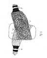
- Ankle brace 1 after the Fig. 1 to 4has a cuff-shaped stocking portion comprising a foot portion 2 and a leg portion 3.
- the stocking sectionis made of flexible, elastically yielding textile material, such as in particular a knitted or knitted fabric.
- the foot region 2forms a closed enveloping body in the circumferential direction. To a toe area of a human foot, the foot area 2 is open.
- the leg region 3is continued in one piece from the foot region 2 and has two opposing side and medially and laterally arranged side regions, which are designed as stabilizing regions 4, 5.
- each stabilization region 4, 5is at least largely provided with a dimensionally stable support insert 6, which in Fig. 1 is indicated.
- the leg areais open, as indicated by the Fig. 1 and 2 is recognizable.
- the leg area 3is partially closed.
- the sock sectionhas a connecting web 15, which is an integral part of the sock section and is accordingly made from the material of the sock section.
- the connecting web 15connects dorsal the medial and the lateral side region of the sock section with each other. This will be through the connecting web 15 and the lateral and medial stabilization regions 4, 5 of the ankle brace 1 connected to each other.
- the connecting web 15can be made relatively wide. Distal connects to the connecting bridge an open section for a heel area of a human foot. Proximal to the connecting web 15, the leg portion 3 is also open.
- the drawstring 12is an open drawstring, which is either not connected to the stocking section at all or only at one of the two side regions. It can be joined together as an annular loop by a free end of the drawstring 12 is provided with hook-and-loop fastener elements which can be fixed on correspondingly designed hook-and-loop fastener elements on an outer side of the drawstring 12.
- the drawstring 12thus has, depending on the design inside and / or outside of correspondingly suitable places Velcro closure elements that allow a releasable fixation of the drawstring in different lengths and in an annular loop.
- both through-loopscan be provided as captive securing devices for the drawstring.
- the drawstring 12is passed through the passage loops 14 and can be pulled out of these or threaded again in this.
- the tension band 12serves as a closed loop in the attached state of the ankle brace 1 for fixing the proximal region of the ankle brace 1 to a corresponding leg of a patient.
- the drawstring 12is opened. After applying the ankle brace 1, the tension band 12 is um The leg is stretched and fixed. As a result, a secure and stable positioning of the stabilization regions 4, 5 is possible.
- each support band 7, 9is fixed to the stocking portion both medially and laterally.
- each support band 7, 9is formed by extending a textile strip, which forms an outer surface of the respective stabilization region 4, 5.
- the textile stripis firmly connected to the stocking section up to the foot region 2, in particular by sewing.
- the width of each support band 7, 9corresponds to the plantar length of the foot region 2 to be supported.
- the plantar side of the foot region 2is designated by the reference numeral 2p.
- each support band 7, 9 - seen in the pulling direction -is chosen so that each support band 7, 9 extends transversely across the Plantarseite 2p of the foot area and can be performed on the opposite side again around the foot area 2 to the leg portion 3 of the sock section ,
- At the respective free end of each support belt 7, 9includes a Switzerlandbandabites 8, 10, which is compared to the width of the support belt 7, 9 made narrower.
- the drawstring sections 8, 10have a length which allows them to be guided into the proximal region of the leg region 3 and fixed there.
- the Werbandabiteseare provided with fastening means in the form of hook-and-loop fastener elements, wherein corresponding Velcro fastener elements are provided on the inner and / or outer side of the respective Werbandabites 8, 10. This makes it possible to circumscribe the respective Werbandabites 8, 10 at a corresponding attachment point and to fix to itself.
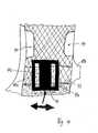
- the lateral stabilization region 5 of the ankle brace 1is assigned a fastening buckle 11 which is provided with two deflection straps 11a, 11b which are provided on opposite sides of the fastening buckle 11.
- the fastening buckle 11itself is by means of a guide web 11 c along a guide band portion 13 in the direction of the double arrow ( Fig. 4 ) limited in the circumferential direction of the leg portion 3 held translationally displaceable.
- the guide strip 13forms a band section extending over the width of the stabilizing region 5, which is firmly connected at its end regions to the stabilizing region 5 or to the socking section.
- the proximal tension band 12is released. Subsequently, the ankle brace 1 is pulled over the human ankle by means of the sock portion until a forefoot portion of the human foot protrudes forward from the foot portion 2 of the sock portion and a heel portion of the human foot has passed below the tie bar 15. Now, the tension band 12 is stretched, so that the stabilization regions 4, 5 are fixed medially and laterally supporting the human ankle joint. Then the two support bands 7, 9 of the lateral or the medial side of each other crossing over and overlapping each other plantar and in the foot area 2 herumgeschlitch ( Fig. 3 ) and then according to Fig.
- Both Werbandabitese 8, 10are fixed by means of appropriate Velcro elements after passing through the corresponding deflecting bow 11 a, 11 b each on themselves.
- first a Switzerlandbandabroughbe fixed relatively loose.
- the tension of this Buchbandabiteses and thus also the associated support bandis then carried out by lashing the opposite Werbandabiteses, since this moves the floating mounted buckle 11 in the circumferential direction and thereby inevitably clamped already fixed to the buckle 11 first Switzerlandbandabrough.
Landscapes
- Health & Medical Sciences (AREA)
- Nursing (AREA)
- Orthopedic Medicine & Surgery (AREA)
- Engineering & Computer Science (AREA)
- Biomedical Technology (AREA)
- Heart & Thoracic Surgery (AREA)
- Vascular Medicine (AREA)
- Life Sciences & Earth Sciences (AREA)
- Animal Behavior & Ethology (AREA)
- General Health & Medical Sciences (AREA)
- Public Health (AREA)
- Veterinary Medicine (AREA)
- Orthopedics, Nursing, And Contraception (AREA)
- Socks And Pantyhose (AREA)
Abstract
Description
Translated fromGermanDie Erfindung betrifft eine orthopädische Sprunggelenkstütze mit einem flexiblen Strumpfabschnitt, der einen Fußbereich und einen Beinbereich umfasst, wobei an dem Beinbereich ein medialer und ein lateraler Stabilisierungsbereich angeordnet sind, und wobei dem Fußbereich wenigstens ein den Fußbereich plantar umspannendes Stützband zugeordnet ist, das zu seinem freien Ende hin in einen Zugbandabschnitt fortgesetzt ist, der Befestigungsmittel zum lösbaren, gespannten Festlegen an einem Befestigungsbereich des Strumpfabschnittes oder eines Stabilisierungsbereiches aufweist.The invention relates to an orthopedic ankle brace comprising a flexible stocking section comprising a foot region and a leg region, wherein a medial and a lateral stabilization region are arranged on the leg region, and wherein the foot region is associated with at least one support band surrounding the foot region plantar to its free end End is continued in a Zugbandabschnitt having fastening means for releasably, taut set at a mounting region of the sock section or a stabilization region.
Eine derartige Sprunggelenkstütze ist aus der
Aufgabe der Erfindung ist es, eine orthopädische Sprunggelenkstütze der eingangs genannten Art zu schaffen, die ein verbessertes Anlegen und eine verbesserte Stützung eines menschlichen Sprunggelenkes ermöglicht.The object of the invention is to provide an orthopedic ankle brace of the type mentioned, which allows an improved application and improved support of a human ankle.
Diese Aufgabe wird dadurch gelöst, dass zwei einander plantar überlappende, sich kreuzende Stützbänder vorgesehen sind, von denen eines medial und das andere lateral an jeweils einem Endbereich mit dem Strumpfabschnitt verbunden sind, und die mittels ihrer Zugbandabschnitte im Beinbereich des Strumpfabschnittes festlegbar sind. Die Stützbänder sind somit an ihren Endbereichen auf gegenüberliegenden Seiten des Strumpfabschnittes festgelegt, nämlich medial und lateral. Beide Stützbänder werden entgegengesetzt zueinander und damit sich kreuzend sowie sich plantar im Fußbereich überlappend plantar um den Fußbereich herumgeführt und anschließend im Beinbereich des Strumpfabschnittes mit den zugehörigen Zugbandabschnitten lösbar unter Spannung befestigt. Vorzugsweise überkreuzen sich die Zugbandabschnitte frontal im distalen Bereich des Beinbereiches des Strumpfabschnittes erneut, um in entgegengesetzten Richtungen um den Beinbereich herumgeführt zu werden. Dadurch, dass die Stützbänder auf gegenüberliegenden Seiten des Fußbereiches angreifen und einander überlappend in entgegengesetzten Richtungen plantar um den Fußbereich herumgeführt sind, führen Zugbelastungen auf die beiden Stützbänder zu einer gleichmäßigen Belastung beider Seiten des Fußbereiches, d.h. sowohl der lateralen als auch der medialen Seite. Je nach gewünschter Stützung kann zudem individuell die laterale oder mediale Seite mit größerer Spannung versehen werden, so dass je nach Indikation eine laterale oder mediale Verlagerung der gewünschten Stützfunktion erzielbar ist. Die beiden voneinander unabhängigen Stützbänder ermöglichen insoweit eine individuelle Anpassung. Die Breite der Stützbänder ist auf die zu stützende, plantare Länge des Fußbereiches abgestimmt. Die Stützbänder selbst sind demzufolge wesentlich breiter als die anschließenden Zugbandabschnitte. Vorzugsweise sind als Befestigungsmittel im Bereich der Zugbandabschnitte Klettverschlusselemente vorgesehen. Es ist vorzugsweise vorgesehen, jeden Zugbandabschnitt innen- oder außenseitig mit den zueinander korrespondierenden Klettverschlusselementen zu versehen, so dass der Zugbandabschnitt durch entsprechendes Umlegen im Bereich einer Befestigungsschlaufe an sich selbst fixierbar ist. Die beiden Stabilisierungsbereiche sind vorzugsweise mit formstabilen Stützeinlagen versehen, die mit den entsprechend medialen und lateralen Bereichen des manschettenartigen Strumpfabschnittes vernäht oder in anderer Art und Weise an diesem fixiert sind.This object is achieved in that two mutually plantar overlapping, intersecting support bands are provided, one of which is connected medially and the other laterally at one end region with the sock section, and which can be fixed by means of their Zugbandabschnitte leg portion of the sock section. The support bands are thus fixed at their end regions on opposite sides of the sock portion, namely medial and lateral. Both support bands are opposite to each other and thus crossing and plantar in the foot area overlapping plantar led around the foot area and then releasably secured in the leg area of the sock section with the associated Zugbandabschnitten under tension. Preferably, the tieback sections frontally intersect in the distal region of the leg region of the sock section again to be passed around the leg region in opposite directions. Due to the fact that the support bands engage on opposite sides of the foot area and overlap each other in opposite directions plantar around the foot area, tensile stresses on the two support bands result in a uniform load on both sides of the foot area, ie both the lateral and the medial side. Depending on desired support can also be individually provided the lateral or medial side with greater tension, so that depending on the indication, a lateral or medial displacement of the desired support function can be achieved. The two independent support bands allow an individual adaptation in this respect. The width of the support bands is matched to the supportive, plantar length of the foot area. The support bands themselves are therefore substantially wider than the subsequent Zugbandabschnitte. Velcro fastening elements are preferably provided as fastening means in the region of the tension band sections. It is preferably provided to provide each Zugbandabschnitt inside or outside with the mutually corresponding hook and loop fastener elements, so that the Zugbandabschnitt is fixed by appropriate folding in the region of a fastening loop to itself. The two stabilizing regions are preferably provided with dimensionally stable support inserts, which are sewn to the corresponding medial and lateral regions of the sleeve-like stocking section or fixed in a different manner thereto.
In Ausgestaltung der Erfindung ist dem Beinbereich des Strumpfabschnittes eine separate, längenveränderbare Ringschlaufe zugeordnet, die zur Fixierung des Beinbereichs an einem proximalen Sprunggelenksbereich eines Patienten beiträgt. Die Ringschlaufe ist im proximalen Bereich des Beinbereiches des Strumpfabschnittes angeordnet und vorzugsweise als separates Zugband ausgeführt, das durch Befestigungsmittel, vorzugsweise in Form von Klettverschlusselementen, lösbar und längenveränderbar fixierbar ist. Vorzugsweise wird die Ringschlaufe somit durch ein offenes Zugband gebildet, das in angelegtem Zustand der Sprunggelenkstütze ringförmig fixierbar ist. Dadurch ist ein einfacher Ein- oder Ausstieg für einen Patienten ermöglicht. Das Fixieren der Ringschlaufe gewährleistet die definierte Positionierung der lateralen und medialen Stabilisierungsbereiche im proximalen Bereich des Beinbereiches der Stütze. Die beschriebene, separate und längenveränderbare Ringschlaufe kann auch für orthopädische Sprunggelenkstützen vorgesehen sein, die - wie eingangs beschrieben - ausgeführt sind. Eine zusätzliche plantare Überlappung von zwei sich kreuzenden Stützbändern im Fußbereich muss bei dieser Ausführung nicht notwendigerweise vorgesehen sein.In an embodiment of the invention, the leg region of the sock section is assigned a separate, variable-length ring loop, which contributes to the fixation of the leg region at a proximal ankle region of a patient. The ring loop is arranged in the proximal region of the leg region of the stocking section and is preferably designed as a separate drawstring, which can be fixed in a detachable manner and length-variable by fastening means, preferably in the form of hook-and-loop fastener elements. Preferably, the ring loop is thus formed by an open drawstring, which is annularly fixed in the applied state of the ankle brace. This allows a simple entry or exit for a patient. The fixation of the ring loop ensures the defined positioning of the lateral and medial stabilization regions in the proximal region of the leg region of the support. The described, separate and variable length Ring loop can also be provided for orthopedic ankle braces, which - as described above - are executed. An additional plantar overlap of two intersecting support bands in the foot area does not necessarily have to be provided in this embodiment.
In weiterer Ausgestaltung der Erfindung ist im Beinbereich des Strumpfabschnittes eine im angelegten Zustand der Sprunggelenkstütze in Umfangsrichtung begrenzt verlagerbare Befestigungsschnalle vorgesehen, die mit in Umfangsrichtung einander gegenüberliegenden Umlenkbügeln für beide Zugbandabschnitte beider Stützbänder versehen ist. Die Befestigungsschnalle ist somit in Umfangsrichtung schwimmend gelagert. Vorteilhaft sind an der Befestigungsschnalle beide Zugbandabschnitte und damit auch beide Stützbänder fixierbar. Der eine Zugbandabschnitt bildet im befestigten Zustand jeweils die Gegenkraft und damit den Gegenhalter für den anderen Zugbandabschnitt. Die Befestigungsschnalle ist somit nach Festlegung beider Zugbandabschnitte in ihrer Position fixiert. Die begrenzte Verlagerbarkeit der Befestigungsschnalle gewährleistet Ausgleichsmöglichkeiten.In a further embodiment of the invention, a limited in the applied state of the ankle brace in the circumferential direction displaceable fastening buckle is provided in the leg area of the sock section, which is provided with circumferentially opposite deflection brackets for both Zugbandabschnitte both support bands. The fastening buckle is thus floating in the circumferential direction. Advantageously, both Zugbandabschnitte and thus both support straps can be fixed to the fastening buckle. The one tension band section forms in the attached state in each case the counterforce and thus the counter holder for the other Zugbandabschnitt. The fastening buckle is thus fixed in position after fixing both Zugbandabschnitte. The limited displaceability of the buckle ensures compensation options.
In weiterer Ausgestaltung der Erfindung weist der Beinbereich des Strumpfabschnittes einen dorsalen Verbindungssteg zwischen dem lateralen und dem medialen Stabilisierungsbereich auf. Dieser dorsale Verbindungssteg ist einstückiger Teil des Strumpfabschnittes oder in anderer Art und Weise unlösbar mit dem medialen und dem lateralen Bereich des Strumpfabschnittes und/oder dem medialen und lateralen Stabilisierungsbereich verbunden.In a further embodiment of the invention, the leg region of the stocking section has a dorsal connecting web between the lateral and the medial stabilization region. This dorsal connecting web is an integral part of the socking section or in other ways permanently connected to the medial and the lateral area of the sock section and / or the medial and lateral stabilization area.
Weitere Vorteile und Merkmale der Erfindung ergeben sich aus der nachfolgenden Beschreibung einer bevorzugten Ausführungsform der Erfindung, die anhand der Zeichnungen dargestellt ist.
- Fig. 1
- zeigt perspektivisch und schematisch eine bevorzugte Ausfüh- rungsform einer erfindungsgemäßen Sprunggelenkstütze in angelegtem Zustand,
- Fig. 2
- die Sprunggelenkstütze nach
Fig. 1 in teilweise geöffnetem Zu- stand, - Fig. 3
- eine plantare Ansicht der Sprunggelenkstütze nach den
Fig. 1 und2 und - Fig. 4
- in vergrößerter Darstellung einen Ausschnitt der Sprungge- lenkstütze nach den
Fig. 1 bis 3 auf Höhe eines lateralen Stabi- lisierungsbereiches der Sprunggelenkstütze.
- Fig. 1
- shows in perspective and schematically a preferred embodiment of an inventive ankle brace in an applied state,
- Fig. 2
- the ankle brace after
Fig. 1 in partially open state, - Fig. 3
- a plantar view of the ankle brace after the
Fig. 1 and2 and - Fig. 4
- in an enlarged view a section of the ankle support after the
Fig. 1 to 3 at the level of a lateral stabilization area of the ankle brace.
Eine Sprunggelenkstütze 1 nach den
An den proximalen Seitenbereichen des Strumpfabschnittes, nämlich medial und lateral, ist jeweils eine Durchtrittsschlaufe 14 vorgesehen, durch die ein Zugband 12 hindurchgeschlauft ist. Das Zugband 12 ist ein offenes Zugband, das mit dem Strumpfabschnitt entweder gar nicht oder lediglich an einem der beiden Seitenbereiche fest verbunden ist. Es ist als ringförmige Schlaufe zusammenfügbar, indem ein freies Ende des Zugbandes 12 mit Klettverschlusselementen versehen ist, die auf korrespondierend gestalteten Klettverschlusselementen an einer Außenseite des Zugbandes 12 festlegbar sind. Das Zugband 12 weist somit je nach Gestaltung innen- und/oder außenseitig an entsprechend geeigneten Stellen Klettverschlusselemente auf, die eine lösbare Fixierung des Zugbandes in unterschiedlichen Längen und in ringförmiger Schlaufe ermöglichen. Die Durchtrittsschlaufe 14 dient als Verliersicherung für das Zugband 12. Falls an beiden Seitenbereichen des Beinbereiches 3 des Strumpfabschnittes jeweils eine Durchtrittsschlaufe 14 vorgesehen ist, können beide Durchtrittsschlaufen als Verliersicherungen für das Zugband vorgesehen sein. Das Zugband 12 ist durch die Durchtrittsschlaufen 14 hindurchgeschlauft und kann aus diesen herausgezogen oder erneut in diese eingefädelt werden. Das Zugband 12 dient als geschlossene Ringschlaufe in angelegtem Zustand der Sprunggelenkstütze 1 zur Fixierung des proximalen Bereiches der Sprunggelenkstütze 1 an einem entsprechenden Bein eines Patienten. Für das Anlegen oder Ausziehen der Sprunggelenkstütze 1 wird das Zugband 12 geöffnet. Nach dem Anlegen der Sprunggelenkstütze 1 wird das Zugband 12 um das Bein herumgespannt und fixiert. Dadurch ist eine sichere und stabile Positionierung der Stabilisierungsbereiche 4, 5 ermöglicht.At the proximal side regions of the sock section, namely medially and laterally, a respective through-
In distaler Verlängerung der Stabilisierungsbereiche 4, 5 ist an dem Strumpfabschnitt sowohl medial als auch lateral jeweils ein Stützband 7, 9 fixiert. Beim dargestellten Ausführungsbeispiel wird jedes Stützband 7, 9 durch Verlängerung eines Textilstreifens gebildet, der eine Außenfläche des jeweiligen Stabilisierungsbereiches 4, 5 bildet. Der Textilstreifen ist bis in den Fußbereich 2 insbesondere durch Vernähen fest mit dem Strumpfabschnitt verbunden. Am Fußbereich 2 des Strumpfabschnittes ragt der Textilstreifen dann frei ab und bildet das eigentliche Stützband 7, 9. Die Breite jedes Stützbandes 7, 9 entspricht der zu stützenden plantaren Länge des Fußbereiches 2. Die Plantarseite des Fußbereiches 2 wird mit dem Bezugszeichen 2p bezeichnet. Die Länge jedes Stützbandes 7, 9 - in Zugrichtung gesehen - ist so gewählt, dass jedes Stützband 7, 9 quer über die Plantarseite 2p des Fußbereiches erstreckt und auf der gegenüberliegenden Seite wieder um den Fußbereich 2 herum zu dem Beinbereich 3 des Strumpfabschnittes geführt werden kann. An das jeweilige freie Ende jedes Stützbandes 7, 9 schließt ein Zugbandabschnitt 8, 10 an, der gegenüber der Breite des Stützbandes 7, 9 schmaler ausgeführt ist. Die Zugbandabschnitte 8, 10 weisen eine Länge auf, die es ihnen ermöglicht, bis in den proximalen Bereich des Beinbereiches 3 geführt zu werden und dort fixiert zu werden.In the distal extension of the
Beim dargestellten Ausführungsbeispiel sind die Zugbandabschnitte mit Befestigungsmitteln in Form von Klettverschlusselementen versehen, wobei zueinander korrespondierende Klettverschlusselemente innen-und/oder außenseitig am jeweiligen Zugbandabschnitt 8, 10 vorgesehen sind. Dadurch ist es möglich, den jeweiligen Zugbandabschnitt 8, 10 an einer entsprechenden Befestigungsstelle umzuschlaufen und an sich selbst zu fixieren.In the illustrated embodiment, the Zugbandabschnitte are provided with fastening means in the form of hook-and-loop fastener elements, wherein corresponding Velcro fastener elements are provided on the inner and / or outer side of the
Zur Fixierung der Zugbandabschnitte 8, 10 am Beinbereich 3 des Strumpfabschnittes ist dem lateralen Stabilisierungsbereich 5 der Sprunggelenkstütze 1 eine Befestigungsschnalle 11 zugeordnet, die mit zwei Umlenkbügeln 11a, 11 b versehen ist, die an gegenüberliegenden Seiten der Befestigungsschnalle 11 vorgesehen sind. Die Befestigungsschnalle 11 selbst ist mittels eines Führungssteges 11 c längs eines Führungsbandabschnittes 13 in Richtung des Doppelpfeiles (
Um die Sprunggelenkstütze 1 anlegen zu können, wird aus einem Zustand der Sprunggelenkstütze 1 gemäß
Claims (4)
Translated fromGermanApplications Claiming Priority (1)
| Application Number | Priority Date | Filing Date | Title |
|---|---|---|---|
| DE200820001405DE202008001405U1 (en) | 2008-01-24 | 2008-01-24 | Orthopedic ankle brace |
Publications (1)
| Publication Number | Publication Date |
|---|---|
| EP2082709A1true EP2082709A1 (en) | 2009-07-29 |
Family
ID=39265488
Family Applications (1)
| Application Number | Title | Priority Date | Filing Date |
|---|---|---|---|
| EP09000844AWithdrawnEP2082709A1 (en) | 2008-01-24 | 2009-01-22 | Orthopaedic ankle joint support |
Country Status (2)
| Country | Link |
|---|---|
| EP (1) | EP2082709A1 (en) |
| DE (1) | DE202008001405U1 (en) |
Cited By (34)
| Publication number | Priority date | Publication date | Assignee | Title |
|---|---|---|---|---|
| US8852239B2 (en) | 2013-02-15 | 2014-10-07 | Roger P Jackson | Sagittal angle screw with integral shank and receiver |
| US8870928B2 (en) | 2002-09-06 | 2014-10-28 | Roger P. Jackson | Helical guide and advancement flange with radially loaded lip |
| US8911478B2 (en) | 2012-11-21 | 2014-12-16 | Roger P. Jackson | Splay control closure for open bone anchor |
| US8926670B2 (en) | 2003-06-18 | 2015-01-06 | Roger P. Jackson | Polyaxial bone screw assembly |
| US8926672B2 (en) | 2004-11-10 | 2015-01-06 | Roger P. Jackson | Splay control closure for open bone anchor |
| US8998960B2 (en) | 2004-11-10 | 2015-04-07 | Roger P. Jackson | Polyaxial bone screw with helically wound capture connection |
| US8998959B2 (en) | 2009-06-15 | 2015-04-07 | Roger P Jackson | Polyaxial bone anchors with pop-on shank, fully constrained friction fit retainer and lock and release insert |
| US9050139B2 (en) | 2004-02-27 | 2015-06-09 | Roger P. Jackson | Orthopedic implant rod reduction tool set and method |
| US9144444B2 (en) | 2003-06-18 | 2015-09-29 | Roger P Jackson | Polyaxial bone anchor with helical capture connection, insert and dual locking assembly |
| US9168069B2 (en) | 2009-06-15 | 2015-10-27 | Roger P. Jackson | Polyaxial bone anchor with pop-on shank and winged insert with lower skirt for engaging a friction fit retainer |
| US9308027B2 (en) | 2005-05-27 | 2016-04-12 | Roger P Jackson | Polyaxial bone screw with shank articulation pressure insert and method |
| US9393047B2 (en) | 2009-06-15 | 2016-07-19 | Roger P. Jackson | Polyaxial bone anchor with pop-on shank and friction fit retainer with low profile edge lock |
| US9451993B2 (en) | 2014-01-09 | 2016-09-27 | Roger P. Jackson | Bi-radial pop-on cervical bone anchor |
| US9504496B2 (en) | 2009-06-15 | 2016-11-29 | Roger P. Jackson | Polyaxial bone anchor with pop-on shank, friction fit retainer and winged insert |
| US9532815B2 (en) | 2004-02-27 | 2017-01-03 | Roger P. Jackson | Spinal fixation tool set and method |
| US9566092B2 (en) | 2013-10-29 | 2017-02-14 | Roger P. Jackson | Cervical bone anchor with collet retainer and outer locking sleeve |
| US9597119B2 (en) | 2014-06-04 | 2017-03-21 | Roger P. Jackson | Polyaxial bone anchor with polymer sleeve |
| US9636146B2 (en) | 2012-01-10 | 2017-05-02 | Roger P. Jackson | Multi-start closures for open implants |
| US9662143B2 (en) | 2004-02-27 | 2017-05-30 | Roger P Jackson | Dynamic fixation assemblies with inner core and outer coil-like member |
| US9662151B2 (en) | 2004-02-27 | 2017-05-30 | Roger P Jackson | Orthopedic implant rod reduction tool set and method |
| US9717533B2 (en) | 2013-12-12 | 2017-08-01 | Roger P. Jackson | Bone anchor closure pivot-splay control flange form guide and advancement structure |
| US9907574B2 (en) | 2008-08-01 | 2018-03-06 | Roger P. Jackson | Polyaxial bone anchors with pop-on shank, friction fit fully restrained retainer, insert and tool receiving features |
| US9918751B2 (en) | 2004-02-27 | 2018-03-20 | Roger P. Jackson | Tool system for dynamic spinal implants |
| US9918745B2 (en) | 2009-06-15 | 2018-03-20 | Roger P. Jackson | Polyaxial bone anchor with pop-on shank and winged insert with friction fit compressive collet |
| US10058354B2 (en) | 2013-01-28 | 2018-08-28 | Roger P. Jackson | Pivotal bone anchor assembly with frictional shank head seating surfaces |
| US10064658B2 (en) | 2014-06-04 | 2018-09-04 | Roger P. Jackson | Polyaxial bone anchor with insert guides |
| US10299839B2 (en) | 2003-12-16 | 2019-05-28 | Medos International Sárl | Percutaneous access devices and bone anchor assemblies |
| US10349983B2 (en) | 2003-05-22 | 2019-07-16 | Alphatec Spine, Inc. | Pivotal bone anchor assembly with biased bushing for pre-lock friction fit |
| US10485588B2 (en) | 2004-02-27 | 2019-11-26 | Nuvasive, Inc. | Spinal fixation tool attachment structure |
| US11147597B2 (en) | 2004-02-27 | 2021-10-19 | Roger P Jackson | Dynamic spinal stabilization assemblies, tool set and method |
| US11229457B2 (en) | 2009-06-15 | 2022-01-25 | Roger P. Jackson | Pivotal bone anchor assembly with insert tool deployment |
| US11234745B2 (en) | 2005-07-14 | 2022-02-01 | Roger P. Jackson | Polyaxial bone screw assembly with partially spherical screw head and twist in place pressure insert |
| US11241261B2 (en) | 2005-09-30 | 2022-02-08 | Roger P Jackson | Apparatus and method for soft spinal stabilization using a tensionable cord and releasable end structure |
| US11419642B2 (en) | 2003-12-16 | 2022-08-23 | Medos International Sarl | Percutaneous access devices and bone anchor assemblies |
Families Citing this family (1)
| Publication number | Priority date | Publication date | Assignee | Title |
|---|---|---|---|---|
| DE102014113363A1 (en)* | 2014-09-17 | 2016-03-17 | Petra Meyer-Clasen | Orthosis, in particular Fußhebeorthese |
Citations (6)
| Publication number | Priority date | Publication date | Assignee | Title |
|---|---|---|---|---|
| DE3916091A1 (en)* | 1989-05-17 | 1990-11-22 | Saniwey Medizinische Lagerungs | Ankle joint support - comprises one piece of deep drawn specified plastic foil |
| US5067486A (en)* | 1990-03-28 | 1991-11-26 | Medical Specialties, Inc. | Ankle stabilizing appliance |
| EP0970670A1 (en)* | 1998-07-10 | 2000-01-12 | Becton Dickinson and Company | Ankle brace with multiple straps |
| US20030233062A1 (en)* | 2002-06-18 | 2003-12-18 | Beiersdorf Inc. | Nonbulky ankle brace for use with footwear |
| DE60017944T2 (en) | 2000-01-24 | 2006-05-11 | Aircast Inc. | ORTHOPEDIC JUMPER SUPPORT |
| US20070049857A1 (en)* | 2005-08-29 | 2007-03-01 | Swede-O, Inc. | Ankle support |
- 2008
- 2008-01-24DEDE200820001405patent/DE202008001405U1/ennot_activeExpired - Lifetime
- 2009
- 2009-01-22EPEP09000844Apatent/EP2082709A1/ennot_activeWithdrawn
Patent Citations (6)
| Publication number | Priority date | Publication date | Assignee | Title |
|---|---|---|---|---|
| DE3916091A1 (en)* | 1989-05-17 | 1990-11-22 | Saniwey Medizinische Lagerungs | Ankle joint support - comprises one piece of deep drawn specified plastic foil |
| US5067486A (en)* | 1990-03-28 | 1991-11-26 | Medical Specialties, Inc. | Ankle stabilizing appliance |
| EP0970670A1 (en)* | 1998-07-10 | 2000-01-12 | Becton Dickinson and Company | Ankle brace with multiple straps |
| DE60017944T2 (en) | 2000-01-24 | 2006-05-11 | Aircast Inc. | ORTHOPEDIC JUMPER SUPPORT |
| US20030233062A1 (en)* | 2002-06-18 | 2003-12-18 | Beiersdorf Inc. | Nonbulky ankle brace for use with footwear |
| US20070049857A1 (en)* | 2005-08-29 | 2007-03-01 | Swede-O, Inc. | Ankle support |
Cited By (44)
| Publication number | Priority date | Publication date | Assignee | Title |
|---|---|---|---|---|
| US8870928B2 (en) | 2002-09-06 | 2014-10-28 | Roger P. Jackson | Helical guide and advancement flange with radially loaded lip |
| US10349983B2 (en) | 2003-05-22 | 2019-07-16 | Alphatec Spine, Inc. | Pivotal bone anchor assembly with biased bushing for pre-lock friction fit |
| US9144444B2 (en) | 2003-06-18 | 2015-09-29 | Roger P Jackson | Polyaxial bone anchor with helical capture connection, insert and dual locking assembly |
| US8926670B2 (en) | 2003-06-18 | 2015-01-06 | Roger P. Jackson | Polyaxial bone screw assembly |
| US8936623B2 (en) | 2003-06-18 | 2015-01-20 | Roger P. Jackson | Polyaxial bone screw assembly |
| US11419642B2 (en) | 2003-12-16 | 2022-08-23 | Medos International Sarl | Percutaneous access devices and bone anchor assemblies |
| US10299839B2 (en) | 2003-12-16 | 2019-05-28 | Medos International Sárl | Percutaneous access devices and bone anchor assemblies |
| US9662143B2 (en) | 2004-02-27 | 2017-05-30 | Roger P Jackson | Dynamic fixation assemblies with inner core and outer coil-like member |
| US11291480B2 (en) | 2004-02-27 | 2022-04-05 | Nuvasive, Inc. | Spinal fixation tool attachment structure |
| US10485588B2 (en) | 2004-02-27 | 2019-11-26 | Nuvasive, Inc. | Spinal fixation tool attachment structure |
| US9050139B2 (en) | 2004-02-27 | 2015-06-09 | Roger P. Jackson | Orthopedic implant rod reduction tool set and method |
| US9918751B2 (en) | 2004-02-27 | 2018-03-20 | Roger P. Jackson | Tool system for dynamic spinal implants |
| US9662151B2 (en) | 2004-02-27 | 2017-05-30 | Roger P Jackson | Orthopedic implant rod reduction tool set and method |
| US11648039B2 (en) | 2004-02-27 | 2023-05-16 | Roger P. Jackson | Spinal fixation tool attachment structure |
| US11147597B2 (en) | 2004-02-27 | 2021-10-19 | Roger P Jackson | Dynamic spinal stabilization assemblies, tool set and method |
| US9636151B2 (en) | 2004-02-27 | 2017-05-02 | Roger P Jackson | Orthopedic implant rod reduction tool set and method |
| US9532815B2 (en) | 2004-02-27 | 2017-01-03 | Roger P. Jackson | Spinal fixation tool set and method |
| US8998960B2 (en) | 2004-11-10 | 2015-04-07 | Roger P. Jackson | Polyaxial bone screw with helically wound capture connection |
| US11147591B2 (en) | 2004-11-10 | 2021-10-19 | Roger P Jackson | Pivotal bone anchor receiver assembly with threaded closure |
| US8926672B2 (en) | 2004-11-10 | 2015-01-06 | Roger P. Jackson | Splay control closure for open bone anchor |
| US11389214B2 (en) | 2004-11-23 | 2022-07-19 | Roger P. Jackson | Spinal fixation tool set and method |
| US9629669B2 (en) | 2004-11-23 | 2017-04-25 | Roger P. Jackson | Spinal fixation tool set and method |
| US9522021B2 (en) | 2004-11-23 | 2016-12-20 | Roger P. Jackson | Polyaxial bone anchor with retainer with notch for mono-axial motion |
| US9308027B2 (en) | 2005-05-27 | 2016-04-12 | Roger P Jackson | Polyaxial bone screw with shank articulation pressure insert and method |
| US11234745B2 (en) | 2005-07-14 | 2022-02-01 | Roger P. Jackson | Polyaxial bone screw assembly with partially spherical screw head and twist in place pressure insert |
| US11241261B2 (en) | 2005-09-30 | 2022-02-08 | Roger P Jackson | Apparatus and method for soft spinal stabilization using a tensionable cord and releasable end structure |
| US9907574B2 (en) | 2008-08-01 | 2018-03-06 | Roger P. Jackson | Polyaxial bone anchors with pop-on shank, friction fit fully restrained retainer, insert and tool receiving features |
| US9504496B2 (en) | 2009-06-15 | 2016-11-29 | Roger P. Jackson | Polyaxial bone anchor with pop-on shank, friction fit retainer and winged insert |
| US9717534B2 (en) | 2009-06-15 | 2017-08-01 | Roger P. Jackson | Polyaxial bone anchor with pop-on shank and friction fit retainer with low profile edge lock |
| US9918745B2 (en) | 2009-06-15 | 2018-03-20 | Roger P. Jackson | Polyaxial bone anchor with pop-on shank and winged insert with friction fit compressive collet |
| US11229457B2 (en) | 2009-06-15 | 2022-01-25 | Roger P. Jackson | Pivotal bone anchor assembly with insert tool deployment |
| US9393047B2 (en) | 2009-06-15 | 2016-07-19 | Roger P. Jackson | Polyaxial bone anchor with pop-on shank and friction fit retainer with low profile edge lock |
| US9168069B2 (en) | 2009-06-15 | 2015-10-27 | Roger P. Jackson | Polyaxial bone anchor with pop-on shank and winged insert with lower skirt for engaging a friction fit retainer |
| US8998959B2 (en) | 2009-06-15 | 2015-04-07 | Roger P Jackson | Polyaxial bone anchors with pop-on shank, fully constrained friction fit retainer and lock and release insert |
| US9636146B2 (en) | 2012-01-10 | 2017-05-02 | Roger P. Jackson | Multi-start closures for open implants |
| US9770265B2 (en) | 2012-11-21 | 2017-09-26 | Roger P. Jackson | Splay control closure for open bone anchor |
| US8911478B2 (en) | 2012-11-21 | 2014-12-16 | Roger P. Jackson | Splay control closure for open bone anchor |
| US10058354B2 (en) | 2013-01-28 | 2018-08-28 | Roger P. Jackson | Pivotal bone anchor assembly with frictional shank head seating surfaces |
| US8852239B2 (en) | 2013-02-15 | 2014-10-07 | Roger P Jackson | Sagittal angle screw with integral shank and receiver |
| US9566092B2 (en) | 2013-10-29 | 2017-02-14 | Roger P. Jackson | Cervical bone anchor with collet retainer and outer locking sleeve |
| US9717533B2 (en) | 2013-12-12 | 2017-08-01 | Roger P. Jackson | Bone anchor closure pivot-splay control flange form guide and advancement structure |
| US9451993B2 (en) | 2014-01-09 | 2016-09-27 | Roger P. Jackson | Bi-radial pop-on cervical bone anchor |
| US10064658B2 (en) | 2014-06-04 | 2018-09-04 | Roger P. Jackson | Polyaxial bone anchor with insert guides |
| US9597119B2 (en) | 2014-06-04 | 2017-03-21 | Roger P. Jackson | Polyaxial bone anchor with polymer sleeve |
Also Published As
| Publication number | Publication date |
|---|---|
| DE202008001405U1 (en) | 2008-04-03 |
Similar Documents
| Publication | Publication Date | Title |
|---|---|---|
| EP2082709A1 (en) | Orthopaedic ankle joint support | |
| EP0372452B1 (en) | Ankle support | |
| EP1629811B1 (en) | Elastic knee joint bandage | |
| WO2007003168A1 (en) | Trunk orthosis | |
| EP2381907B1 (en) | Ankle joint bandage | |
| EP3210581B1 (en) | Foot bandage for compression therapy of lymphedema | |
| EP3716806B1 (en) | Hallux valgus sandal with at least one hallux loop section and a holding loop section | |
| DE102016113219A1 (en) | Elastic band for holding a person's ankle and ankle orthosis | |
| EP2491895A1 (en) | Ankle joint orthosis | |
| DE19855923B4 (en) | Bandage for body parts | |
| DE202016106817U1 (en) | Orthosis, in particular gonarthrosis orthosis | |
| DE102009025416B4 (en) | Support or Fixiergurt | |
| EP1459713B1 (en) | Tubular compression bandage | |
| EP3090709B1 (en) | Orthosis for treatment | |
| EP3661382B1 (en) | Shoe for damping a foot movement via the ankle joint | |
| WO2016119798A1 (en) | Ankle orthesis | |
| EP2666445B1 (en) | Ankle joint orthesis | |
| EP3351220B1 (en) | Compression textile for postsurgical compression treatment of a physical extremity | |
| DE102013114839A1 (en) | Supporting device for raising a foot | |
| DE202013105928U1 (en) | Supporting device for raising a foot | |
| DE102022116790B4 (en) | Device for limiting and/or dampening a foot movement via the ankle joint, and shoe | |
| DE102012011718A1 (en) | Spine orthosis for e.g. treatment of diseases of lumbar spine, has tension band guided through strap ring, and two flexible bars arranged at fixing part for stiffening orthosis and aligned in longitudinal direction to spinal column | |
| DE202020100383U1 (en) | Knee brace | |
| DE102020101745A1 (en) | Knee brace | |
| DE202017006611U1 (en) | Wrist orthosis and tension system for a wrist orthosis |
Legal Events
| Date | Code | Title | Description |
|---|---|---|---|
| PUAI | Public reference made under article 153(3) epc to a published international application that has entered the european phase | Free format text:ORIGINAL CODE: 0009012 | |
| AK | Designated contracting states | Kind code of ref document:A1 Designated state(s):AT BE BG CH CY CZ DE DK EE ES FI FR GB GR HR HU IE IS IT LI LT LU LV MC MK MT NL NO PL PT RO SE SI SK TR | |
| AX | Request for extension of the european patent | Extension state:AL BA RS | |
| AKX | Designation fees paid | ||
| STAA | Information on the status of an ep patent application or granted ep patent | Free format text:STATUS: THE APPLICATION IS DEEMED TO BE WITHDRAWN | |
| 18D | Application deemed to be withdrawn | Effective date:20100130 | |
| REG | Reference to a national code | Ref country code:DE Ref legal event code:8566 |