EP2081619B1 - Connector for use in single and double breast pumping - Google Patents
Connector for use in single and double breast pumpingDownload PDFInfo
- Publication number
- EP2081619B1 EP2081619B1EP07861406.2AEP07861406AEP2081619B1EP 2081619 B1EP2081619 B1EP 2081619B1EP 07861406 AEP07861406 AEP 07861406AEP 2081619 B1EP2081619 B1EP 2081619B1
- Authority
- EP
- European Patent Office
- Prior art keywords
- tube
- connector
- port
- plug member
- receptacle
- Prior art date
- Legal status (The legal status is an assumption and is not a legal conclusion. Google has not performed a legal analysis and makes no representation as to the accuracy of the status listed.)
- Active
Links
- 210000000481breastAnatomy0.000titleclaimsdescription51
- 238000005086pumpingMethods0.000titledescription28
- 239000012530fluidSubstances0.000claimsdescription20
- 238000004891communicationMethods0.000claimsdescription11
- 230000037361pathwayEffects0.000claimsdescription2
- 238000007789sealingMethods0.000description13
- 230000000712assemblyEffects0.000description5
- 238000000429assemblyMethods0.000description5
- 230000008901benefitEffects0.000description4
- 210000004251human milkAnatomy0.000description4
- 235000020256human milkNutrition0.000description4
- 235000013336milkNutrition0.000description4
- 239000008267milkSubstances0.000description4
- 210000004080milkAnatomy0.000description4
- 239000013536elastomeric materialSubstances0.000description3
- 230000008859changeEffects0.000description2
- 230000000474nursing effectEffects0.000description2
- 0C*1C(C2C3)C2C3C1Chemical compoundC*1C(C2C3)C2C3C10.000description1
- 230000009471actionEffects0.000description1
- 230000002411adverseEffects0.000description1
- 230000004888barrier functionEffects0.000description1
- 238000010276constructionMethods0.000description1
- 230000006870functionEffects0.000description1
- 230000006872improvementEffects0.000description1
- 238000004519manufacturing processMethods0.000description1
- 239000000463materialSubstances0.000description1
- 210000002445nippleAnatomy0.000description1
- 230000000737periodic effectEffects0.000description1
- 230000000717retained effectEffects0.000description1
- 230000007704transitionEffects0.000description1
Images


Classifications
- A—HUMAN NECESSITIES
- A61—MEDICAL OR VETERINARY SCIENCE; HYGIENE
- A61M—DEVICES FOR INTRODUCING MEDIA INTO, OR ONTO, THE BODY; DEVICES FOR TRANSDUCING BODY MEDIA OR FOR TAKING MEDIA FROM THE BODY; DEVICES FOR PRODUCING OR ENDING SLEEP OR STUPOR
- A61M1/00—Suction or pumping devices for medical purposes; Devices for carrying-off, for treatment of, or for carrying-over, body-liquids; Drainage systems
- A61M1/06—Milking pumps
- A61M1/062—Pump accessories
- A—HUMAN NECESSITIES
- A61—MEDICAL OR VETERINARY SCIENCE; HYGIENE
- A61M—DEVICES FOR INTRODUCING MEDIA INTO, OR ONTO, THE BODY; DEVICES FOR TRANSDUCING BODY MEDIA OR FOR TAKING MEDIA FROM THE BODY; DEVICES FOR PRODUCING OR ENDING SLEEP OR STUPOR
- A61M39/00—Tubes, tube connectors, tube couplings, valves, access sites or the like, specially adapted for medical use
- A61M39/10—Tube connectors; Tube couplings
- A—HUMAN NECESSITIES
- A61—MEDICAL OR VETERINARY SCIENCE; HYGIENE
- A61M—DEVICES FOR INTRODUCING MEDIA INTO, OR ONTO, THE BODY; DEVICES FOR TRANSDUCING BODY MEDIA OR FOR TAKING MEDIA FROM THE BODY; DEVICES FOR PRODUCING OR ENDING SLEEP OR STUPOR
- A61M39/00—Tubes, tube connectors, tube couplings, valves, access sites or the like, specially adapted for medical use
- A61M39/22—Valves or arrangement of valves
- A61M39/223—Multiway valves
Definitions
- the present inventionrelates to breastpumps, and more specifically to a breastpump system or assembly which can be used in both single and double pumping modes of operation.
- the inventionincludes a connector, which permits a variety of configurations to enable use of a breastpump in either single or double pumping modes.
- Breastmilk pumpsare well-known, and generally comprise a hood, or shield, which fits over the breast.
- a vacuum pumpis connected to the shield for generating an intermittent vacuum (i.e., negative pressure) within the shield.
- a receptacleis provided in communication with the shield for receiving the breast milk expressed during operation of the pump.
- the action of the pumpcreates an intermittent vacuum within the shield, which serves to create an environment reminiscent of suckling and thus, causes expression of breast milk from the mother's breast.
- the milk so expressedis ordinarily collected in a bottle or other container for storage and later use.
- Such breast pumpsare disclosed in U.S. Patent Nos. 4,857,051 ; 5,007,899 ; and 5,071,403 for example.
- Medela, Inc.provides a multi-port connector for use with its commercialized CLASSIC vacuum pump apparatus.
- a double-pumping modetwo airlines connect to a pair of ports in a connector, which in turn is connected to a pump.
- the airlinesare individually connected to two breast pump assemblies (to convey changes in pressure to the connected breast shields).
- Two adaptersare further provided, each containing a milk barrier to prevent milk from reaching the vacuum pump.
- Each adapteris releasably attached to a respective breast pump assembly through a threaded engagement.
- single pumpingis achieved by removing one of the tubes from the connector to disconnect the breastshield.
- a plugis inserted into the joint or receptacle from which the tube was removed so that suction is achieved only in the remaining breastshield.
- the userhas to disconnect the tube from both the shield and the joint and plug the joint to inactivate one of the two breast shields.
- the suction level for single pumpingcan be higher due to the loss in fluid volume compared with two breast shields.
- the removed tubingcan be misplaced or lost.
- U.S. Patent No. 5,720,722is a connector for use in single and double breast pumping.
- This connectorhas a tubular housing with an internal wall extending across the housing interior to divide it into two chambers.
- One chamberhas an outlet for attachment to an air tube for single breast pumping, while the second chamber has two outlets for attachment to two air tubes for double breast pumping.
- the tube from the inactive breastshieldis removed from the breast pump and a plug is inserted into the open port of the pump to close it off.
- the plugmay also provide for a predetermined amount of air leakage to simulate the load of the disconnected breastshield, so that the single shield pumping suction level is substantially the same to the double pumping vacuum level.
- the usermay accidentally tangle the two tubes, either during storage, setup, or use. Tangled tubes can also lead to a nursing mother accidentally disconnecting the incorrect breastshield when single breast pumping is desired.
- a breastpumpthat eliminates a significant number of connections and attachment parts for transition between single and double breast pumping would be considered a desired improvement in the art, thereby facilitating easier use of a breast pump and yielding fewer parts for the user to carry, clean, misplace or manipulate.
- US 5333 606discloses an accessory adaptor for a respirator, wherein this adaptor has to be plugged into an adaptor port of a manifold and wherein this accessory adaptor comprises a leakage path.
- US 4 566 480discloses a connector according to the preamble of claim 1.
- An aspect of the present inventioneliminates a significant number of attachment parts, and the need for adapters, to provide a breast pump which uses fewer connections and attachments, thereby facilitating easier use of the breast pump and yielding fewer pieces for the user to carry, clean, misplace or manipulate.
- a further objectiveis to provide a connector that is readily used in either a single or double pumping mode through an easy and effective engagement of a fluid conveying device.
- An aspect of the inventionprovides a connector according to claim 1, this connector including a manifold.
- the manifoldincludes a three-way passageway formed therethrough.
- the manifoldincludes a first port, a second port, a third port and a fourth port.
- the first, second and third portsare in fluid communication with the three-way passageway.
- a first tubeis connected to and in fluid communication with the first port.
- a second tubeis connected to and in fluid communication with the second port and a third tube is connected to and in fluid communication with the third port.
- the third tubeis sized and shaped to be connectable to a vacuum source, and the fourth port is sized and US 4566 480 discloses a connector according to the preamble of claim 1. shaped to receive one of the first tube and the second tube and permit a predetermined amount of fluid to pass by way of a leakage path. The leakage path is formed in the manifold.
- Preferred embodiments of the inventioninclude a plug member that terminates each tube.
- the first tubeterminates with a first plug member
- the second tubeterminates with a second plug member
- the third tubeterminates with a third plug member.
- the third plug memberis sized and shaped to be connectable to a vacuum source and the fourth port is sized and shaped to receive one of the first plug member and the second plug member.
- Another preferred embodimentincludes a plug member within the fourth port of the manifold.
- One of the first tube or second tubeis adapted to connect to the plug member of the fourth port.
- the fourth portmay include an O-ring disposed therein, the O-ring including a pathway formed thereon for permitting air to be drawn therepast.
- the three-way passagewaymay be a T-shaped or Y-shaped passageway formed in the manifold.
- the plug membersmay engage with a respective one of the ports in a substantially fluid tight fit.
- a connector according to claim 1which includes a connector body having four spaced ports, a first tube extending from a first of the four ports with a first tube end adapted to connect to the source of intermittent vacuum.
- a second tubeextends from a second of the four ports with a second tube end adapted to connect to one of the first and second breast shields.
- a third tubeextends from a third of the four ports with a third tube end adapted to connect to the other of the first and second breast shields.
- a passagewayis formed in a central body of the connector, the passageway fluidly connecting the first, second and third tubes, and a fourth of the four ports adapted to receive one of the second and third tube ends and functioning to substantially seal the received tube end.
- the passagewaymay be a three-way passageway.
- the passagewaymay be a T-shaped or Y-shaped passageway.
- the fourth of the four portsmay be substantially sealed and provided with a predetermined amount of leakage.
- the connector of the present inventionwill be described herein in use with a breastpump assembly, but it is contemplated that the connector of the present invention can be used in any device that may benefit from this type of connector.
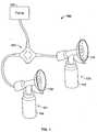
- a breastpump assembly 100' for pumping two breasts simultaneously or a single breastshows, in FIG. 1 , a vacuum pump 102', which is used to generate a periodic change in pressure or intermittent vacuum.
- the generated change in pressure from the pump 102'is then transmitted through connector 200'.
- the connector 200'may be configured to supply changes in pressure to breastshield assemblies 104', 106' simultaneously or only one of the two assemblies.
- vacuumis meant to denote a pressure less than ambient and in one configuration of the connector 200' is supplied to the breast shields 108', 110', and through the breast shields applied to a breast placed therein to express milk.
- Reference to a tube or passage hereafter as an “air” tube or a “vacuum” tubeis not intended to be limiting.
- the breast shield assemblies 104', 106'may each include, in addition to the shields 108', 110', a respective conduit structure 112', 114'.
- Each respective conduit structure 112', 114'is typically provided in fluid communication with a collecting container, a bottle or the like, 116', 118'.
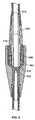
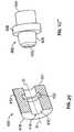
- FIGS. 2 and 3illustrate a connector 200' according to the illustrated embodiment of the present invention in a single pumping and a double pumping configuration, respectively.
- the connector 200'includes a manifold 202'.
- the manifold 202'is a central body including four spaced receptacles or ports, 204', 206', 208', and 210'.
- the connector 200'includes three tubes, a first tube 212', a second tube 216' and a third tube 220'.
- a first tube 212'is connected to and extends from port 204' and may further include a first plug member 214' at a terminal end thereof.
- a second tube 216'is connected to and extends from port 206' and may further include a second plug member 218' at a terminal end thereof.
- a third tube 220'is connected to and extends from port 208' and may further include a third plug member 222' at a terminal end thereof.
- Tubes 212', 216', 220'are preferably permanently affixed within ports 204', 206', 208' such that tubes 212', 216', 220' are not detachable from the manifold, which is considered one advantage over the prior art.
- the port or dock port 210'includes a tube connector arrangement (see FIG. 4 ), as disclosed and described in FIGS. 6-25 .
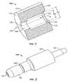
- FIG. 6is an exploded view of a first embodiment of a tubing connector 100.
- the tubing connector 100includes a receptacle 102, a sealing ring 104, a latching component 106 and a plug member 108.
- receptacle 102has an exterior surface 110, a first interior surface 112 and a second interior surface 114, the first and second interior surfaces 112, 114 define a bore 116 therethrough.
- the receptacle 102is not necessarily a separate piece as depicted, but is more typically made integral with something within which the plug 108 is to connect.
- Receptacle 102may therefore be a piece that is assembled to, for example, a motor drive as shown hereafter, or could be formed integral therewith.
- "Receptacle”is therefore used to generally also refer to a well, socket, orifice and the like.
- an axis Aextends into bore 116.
- Bore 116has a first portion 118 defined by first interior surface 112 and a second portion 120 defined by second interior surface 114.
- First portion 118has a first diameter D1 and second portion 120 has a second diameter D2.
- the first interior surface 112further includes a circumferential groove or channel 122.
- Receptacle 102includes two ends 119, 121.
- the first end 119 of receptacle 102is adapted, for instance, to be connected to a motor drive unit of a breast pump assembly, or formed integrally therewith, as shown in FIGS. 11-13 .
- the second end 121 of receptacle 102receives other components of a tube connector therein, as will be described in detail below.
- plug member 108has a base 124 and a stem 126.
- the base 124is adapted to be attached to a tube (not shown) via a nipple 127.
- the stem 126extends axially from the opposite end of the base 124.
- a passageway 125extends through the plug member 108 between the base 124 and the stem 126 for conveying fluid/air.
- the stem 126has a circumferential groove or channel 128 therein, and is adapted to be received within the latching component 106 (see FIG. 9 ).
- Latching componentis preferably formed of an elastomeric material allowing deflection for securing parts of the tubing connector and providing a seal therebetween.
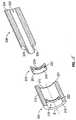
- the latching component 106 of FIG. 9is in the form of a sleeve sized and shaped to receive the stem 126 of plug member 108 therein, and in turn to be received in the first portion 118 of bore 116 of receptacle 102.
- Latching component 106includes an interior surface 109 and exterior surface 107, exterior surface 107 having a circumferential ridge 132 thereon; here, one ridge 132 does not go completely around the circumference.
- Latching component 106further includes two resilient tabs 134 spaced diametrically opposite one another, although any number of tabs is contemplated. The tabs 134 are connected (e.g., made integral) at one end 111 to the latch component 106 in a hinge-like arrangement.
- each resilient tab 134has a rib 136 ( FIG. 10 ) extending past the inside surface 109 and slightly within the interior of the latching component 106.
- the ridge 132which is a partial ring, engages with the groove 122 of the first interior surface 112 of the receptacle 102 when the latching component 106 is inserted into the first portion 118 through bore 116 of receptacle 102.
- the rib 136is arranged to resiliently engage with circumferential channel 128 on stem 126 of plug member 108 when inserting plug member 108 into latching component 106.
- FIG. 10One manner of assembly of the receptacle 102, sealing ring 104, latching component 106 and plug member 108 is shown in FIG. 10 .
- Sealing ring 104is inserted axially into the first portion 118 of bore 116 of the receptacle 102.
- the sealing ring 104has an outer diameter D 1 that fits within first portion 118 of bore 116, and greater than D2 of second portion 120 of bore 116 such that sealing ring 104 abuts the second portion 120 of bore 116.
- the latching component 106is then inserted into the first portion 118 of bore 116 abutting sealing ring 104 forming an airtight seal, and circumferential ridge 132 engages with the groove 122 of the first interior surface 112 of the receptacle 102.
- the latching component 106is secured within receptacle 102 in a manner such that the latching component 106 does not move axially within receptacle 102, although it is contemplated that the latching component 106 and receptacle 102 could have a rotatable engagement.
- the stem 126 of the plug member 108is inserted into latching component 106.
- Latching componentis preferably formed of a plastic material.
- receptacle 102can be formed integrally with the motor drive unit of a breast pump assembly. Assembly of the tube connector 100 in this embodiment is similar to that described above. Sealing ring 104 is inserted axially into the first portion 118 of bore 116 of the receptacle 102 such that sealing ring 104 abuts the second portion 120 of bore 116. The latching component 106 is inserted as previously described with circumferential ridge 132 engaging with the groove 122, securing the latching component 106 within receptacle 102.
- Plug member 108can then be releasably inserted into latching component 106, with tabs 134 resiliently engaging with the circumferential channel 128 on stem 126, to secure the plug member 108 within latching component 106 and thus within receptacle 102.
- FIG. 14is an exploded view of a second embodiment of a tubing connector 200.
- This second embodiment tubing connector 200includes a receptacle 202, a latching component 206 and a plug member 208.
- this receptacle 202has an exterior surface 210 and an interior surface 212, interior surface 212 defining a bore 216 therethrough.
- An axis Bis defined extending into bore 216.
- the interior surface 212has a ring or protrusion 222 thereon around its entire circumference.
- Receptacle 202includes two ends 219, 221.
- the first end 219 of receptacle 202is adapted, for instance, to be connected to a motor drive unit of a breast pump assembly, or formed integrally therewith.
- the second end 221 of receptacle 202receives other components of tube connector 200 therein as will be described in detail.
- plug member 208is adapted at one end 224 to be attached to a tube (not shown).
- the tubecould then be formed integral therewith, or otherwise connected to passageway 225.
- a stubby stem 226extends axially from the opposite end of base 224.
- Passageway 225extends through the plug member 208 between the end 224 and the stem end 226 for conveying fluid/air.
- the stem 226has a circumferential groove or channel 228 therein adapted to be received within the latching component 206.
- this latching component 206is likewise in the form of a sleeve sized and shaped to receive the stem 226 of plug member 208 therein, and to be received in the bore 216 in this type of receptacle 202.
- Modified latching component 206includes an interior surface 209 and exterior surface 207. Exterior surface 207 has a circumferential groove or channel 232 thereon that engages with the ring 222 on the interior surface 212 of the receptacle 202 ( FIG. 17 ) when the latching component 206 is inserted into the bore 216 in receptacle 202.
- Latching component 206further includes a rib or ridge 234 on its interior 209 sized and shaped to match ( FIG.
- latching component 206is inserted axially into the bore 216, and groove 232 engages with the protrusion 222 on the interior surface 212 of the receptacle 202 which secures the latching component 206 within receptacle 202.
- the stem 226 of the plug member 208is inserted into latching component 206 and the rib 234 engages with the circumferential groove 228 on stem 226 which secures the plug member 208 within latching component 206 and thus within receptacle 202.
- the engagement between the rib 234 and the circumferential groove 228is such that the plug member 208 can rotate freely within the latching component 206.
- Latching componentis preferably formed of an elastomeric material allowing deflection for securing parts of the tubing connector and providing a seal therebetween.
- FIG. 20is an exploded view of a third embodiment of a tubing connector 300.
- This third embodiment tubing connector 300includes a receptacle 302, a latching component 306 and a plug member 308.
- receptacle 302has an exterior surface 310 and an interior surface 312, interior surface 312 defining a bore 316 therethrough. An axis C is defined extending into bore 316.
- the interior surface 312has a circumferential lip 322 thereon around its entire circumference.
- Receptacle 302includes two ends 319, 321.
- the first end 319 of receptacle 302is adapted, for instance, to be connected to a motor drive unit of a breast pump assembly, or formed integrally therewith.
- the second end 321 of receptacle 302receives other components of tube connector 300 therein as will be described in detail.
- latching component 306includes an interior surface 309 and a circumferential groove or channel 332 on the outboard side. Groove 332 is annular in form, being located beneath an overlying lip 333. Latching component 306 further includes a shoulder 334 on its interior 309 sized and shaped to match the circumferential groove 328 ( FIG. 20 ) in stem 326 of plug member 308 such that when plug member 308 is inserted into latching component 306 ( FIG. 23 ), shoulder 334 engages circumferential groove 328, which secures plug member 308 within latching component 306.
- plug member 308has an end 324 adapted to be attached to a tube (not shown) in any number of well known ways.
- a stem 326( FIG. 20 ) extends axially from the opposite end of the plug member 308.
- a passageway 325extends through the plug member 308 between the base 324 and the stem 326 for conveying fluid/air.
- Latching component 306is sized and shaped to receive the stem 326 of plug member 308 therein, and to be received in the bore 316 in receptacle 302.
- the groove 332 of latching component 306engages with the lip 322 along the interior surface 312 of the receptacle 302, with lip 333 thereby snapping into place within a channel 335 formed between the lip 322 and adjacent sidewall of the receptacle 302 when the latching component 306 is inserted into the bore 316 in receptacle 302. This is a snap-fit between the receptacle 302 and latching component 306, and these elements are so sized to thus engage.
- latching component 306is inserted axially into the bore 316, and groove 332 engages with the lip 322 on the interior surface 312 of the receptacle 302 which secures the latching component 306 within receptacle 302.
- the stem 326 of the plug member 308is inserted into the combined latching component 306 and receptacle 302, and the shoulder 334 engages with the circumferential groove 328 on stem 326, thus securing the plug member 308 within latching component 306 and within receptacle 302.
- the engagement between the shoulder 334 and the circumferential groove 328is such that the plug member 308 can rotate freely within the latching component 306.
- Latching componentis preferably formed of an elastomeric material allowing deflection for securing parts of the tubing connector and providing a seal therebetween.
- receptacle 402has an exterior surface 410, and an interior surface 412.
- the interior surface 412defines a bore 416 therethrough.
- An axis Dextends into bore 416.
- a circumferential groove 422is formed around the interior surface 412.
- Receptacle 402includes two ends 419, 421.
- the first end 419 of receptacle 402is adapted, for instance, to be connected to a motor drive unit of a breast pump assembly, or formed integrally therewith.
- the second end 421 of receptacle 402receives other components of yet another tube connector therein, as will be described in detail below.
- the plug member 408has an end 424 and a stem 426.
- the end 424is adapted to be attached to a tube (not shown) in any of many known ways.
- the stem 426extends axially from the opposite end of the base 424.
- a passageway 425extends through the plug member 408 between the end 424 and the stem 426 for conveying fluid/air.
- sealing member 404is sized to fit in the circumferential groove 422 of the interior surface 412 of the receptacle 402.
- This seal member 404engages the circumferential groove 428 of the plug member 408 when plug member 408 is inserted into the bore 416 of the receptacle 402 thereby forming an air-tight seal, acting to retain the plug member 408 within the receptacle 402 by resisting removal forces, and also allowing the plug member 408 to rotate freely within the receptacle 402.
- the receptacle 402could be integral with a housing and further include a shoulder surface on the interior 412, similar to embodiments previously described, for engagement with a plug member.
- a component retained within the bore, or a surface integral with the receptaclecould define and function as a sealing member. There are many contemplated embodiments that serve to simplify fabrication and assembly.
- the port 210'permits connection and disconnection of either tube 214', 216' when single breast pumping is desired. More particularly, port 210' permits connection and disconnection of either of plug members 214', 218' when single breast pumping is desired.
- Plug member 222'when engaged with an operating vacuum pump transmits changes in pressure from the pump to the manifold 202' and through tubes 212' and 216' to one or both of the breastpump assemblies.
- one of either tube 212' or tube 216'is disconnected from the respective breastpump assembly and docked or engaged with port 210'.
- the plug 214'or 218'(depending on which single breast a nursing mother wishes to pump) engages with the tube connector arrangement within dock port 210' and changes in pressure generated by the pump are conveyed through the manifold 202' to the tube not connected to dock port 210'.
- the dock port 210'can include a plug member such that either tube 212' or tube 216' can connect thereto.
- the tube connector arrangement within port 210'includes a sealing ring 304' and latching component 306', again fully described herein and shown in FIGS 6-25 , for engagement with plug connector 214' or 218' (here, 218').
- the manifold 202'includes a three-way, or T-shaped or Y-shaped, flow passage 302' to convey the vacuum from the pump to the connector 200' and into separate air paths via tube 212' and/or 216' depending on whether single or double breast pumping is implemented.
- the passage 302'is not connected to port 210'.
- plug member 214'connects tube 212' to a first breastpump assembly and plug member 218' connects tube 216' to a second breastpump assembly.
- Port 210'does not need to be plugged or capped off since the T-shaped flow passage 302' (see FIG. 5 ) conveys pressure changes to each tube 212', 216'.
- plug connector 218'is engaged with port 210'.
- plug connector 214'can engage with port 210' depending on which breast the mother desires to pump.
- port 210'provides a predetermined amount of air leakage to simulate the load of the disconnected breastshield, so that the single shield pumping suction level is substantially the same to the double pumping vacuum level.
- two air leakage paths A, Bare formed in port 210' such that the disconnected breastshield does not, to a great extent, adversely affect vacuum levels transmitted to the operating breastshield.
- Path Aleaks air past both the sealing ring 304' and latching component 306' whereas path B leaks air past the sealing ring 304' and between the latching component 306' and plug member 218'.
- the leaked airtravels into from outside the manifold 202'.
- the leaked airmay take any path, including a path through the manifold itself.
Landscapes
- Health & Medical Sciences (AREA)
- Heart & Thoracic Surgery (AREA)
- Biomedical Technology (AREA)
- Vascular Medicine (AREA)
- Engineering & Computer Science (AREA)
- Anesthesiology (AREA)
- Pediatric Medicine (AREA)
- Hematology (AREA)
- Life Sciences & Earth Sciences (AREA)
- Animal Behavior & Ethology (AREA)
- General Health & Medical Sciences (AREA)
- Public Health (AREA)
- Veterinary Medicine (AREA)
- External Artificial Organs (AREA)
Description
- The present invention relates to breastpumps, and more specifically to a breastpump system or assembly which can be used in both single and double pumping modes of operation. In particular, the invention includes a connector, which permits a variety of configurations to enable use of a breastpump in either single or double pumping modes.
- Breastmilk pumps are well-known, and generally comprise a hood, or shield, which fits over the breast. A vacuum pump is connected to the shield for generating an intermittent vacuum (i.e., negative pressure) within the shield. A receptacle is provided in communication with the shield for receiving the breast milk expressed during operation of the pump.
- The action of the pump creates an intermittent vacuum within the shield, which serves to create an environment reminiscent of suckling and thus, causes expression of breast milk from the mother's breast. The milk so expressed is ordinarily collected in a bottle or other container for storage and later use. Such breast pumps are disclosed in
U.S. Patent Nos. 4,857,051 ;5,007,899 ; and5,071,403 for example. - It is also well-known to provide a breast pump which can be used in both single (one breast) and double (both breasts) modes of operation, i.e., expressing breast milk from one breast at a time or simultaneously. For example, Medela, Inc., to which the present invention is assigned, provides a multi-port connector for use with its commercialized CLASSIC vacuum pump apparatus. In a double-pumping mode, two airlines connect to a pair of ports in a connector, which in turn is connected to a pump. The airlines are individually connected to two breast pump assemblies (to convey changes in pressure to the connected breast shields). Two adapters are further provided, each containing a milk barrier to prevent milk from reaching the vacuum pump. Each adapter is releasably attached to a respective breast pump assembly through a threaded engagement. This arrangement using the connector including two adapters of the foregoing type is disclosed in
U.S. Patent No. 5,071,403 . - With the above noted configuration, single pumping is achieved by removing one of the tubes from the connector to disconnect the breastshield. A plug is inserted into the joint or receptacle from which the tube was removed so that suction is achieved only in the remaining breastshield. In using this design, the user has to disconnect the tube from both the shield and the joint and plug the joint to inactivate one of the two breast shields. The suction level for single pumping can be higher due to the loss in fluid volume compared with two breast shields. The removed tubing can be misplaced or lost.
U.S. Patent No. 5,720,722 is a connector for use in single and double breast pumping. This connector has a tubular housing with an internal wall extending across the housing interior to divide it into two chambers. One chamber has an outlet for attachment to an air tube for single breast pumping, while the second chamber has two outlets for attachment to two air tubes for double breast pumping.- In this configuration, when a woman wants to only pump one breast, the tube from the inactive breastshield is removed from the breast pump and a plug is inserted into the open port of the pump to close it off. The plug may also provide for a predetermined amount of air leakage to simulate the load of the disconnected breastshield, so that the single shield pumping suction level is substantially the same to the double pumping vacuum level. However, the user may accidentally tangle the two tubes, either during storage, setup, or use. Tangled tubes can also lead to a nursing mother accidentally disconnecting the incorrect breastshield when single breast pumping is desired.
- Thus, a breastpump that eliminates a significant number of connections and attachment parts for transition between single and double breast pumping would be considered a desired improvement in the art, thereby facilitating easier use of a breast pump and yielding fewer parts for the user to carry, clean, misplace or manipulate.
US 5333 606 discloses an accessory adaptor for a respirator, wherein this adaptor has to be plugged into an adaptor port of a manifold and wherein this accessory adaptor comprises a leakage path.US 4 566 480 discloses a connector according to the preamble of claim 1.- An aspect of the present invention eliminates a significant number of attachment parts, and the need for adapters, to provide a breast pump which uses fewer connections and attachments, thereby facilitating easier use of the breast pump and yielding fewer pieces for the user to carry, clean, misplace or manipulate.
- A further objective is to provide a connector that is readily used in either a single or double pumping mode through an easy and effective engagement of a fluid conveying device.
- An aspect of the invention provides a connector according to claim 1, this connector including a manifold. The manifold includes a three-way passageway formed therethrough. The manifold includes a first port, a second port, a third port and a fourth port. The first, second and third ports are in fluid communication with the three-way passageway. A first tube is connected to and in fluid communication with the first port. A second tube is connected to and in fluid communication with the second port and a third tube is connected to and in fluid communication with the third port. The third tube is sized and shaped to be connectable to a vacuum source, and the fourth port is sized and
US 4566 480 discloses a connector according to the preamble of claim 1. shaped to receive one of the first tube and the second tube and permit a predetermined amount of fluid to pass by way of a leakage path. The leakage path is formed in the manifold. - Preferred embodiments of the invention include a plug member that terminates each tube. The first tube terminates with a first plug member, the second tube terminates with a second plug member and the third tube terminates with a third plug member. The third plug member is sized and shaped to be connectable to a vacuum source and the fourth port is sized and shaped to receive one of the first plug member and the second plug member.
- Another preferred embodiment includes a plug member within the fourth port of the manifold. One of the first tube or second tube is adapted to connect to the plug member of the fourth port.
- Other preferred embodiments of the invention provide the first, second and third tubes non-removably connected to the manifold. The fourth port may include an O-ring disposed therein, the O-ring including a pathway formed thereon for permitting air to be drawn therepast. The three-way passageway may be a T-shaped or Y-shaped passageway formed in the manifold. The plug members may engage with a respective one of the ports in a substantially fluid tight fit.
- Another embodiment of the invention provides a system for breastpumping in a single breastpumping mode or a double breastpumping mode, including a source of intermittent vacuum. First and second breast shields are connectable to the source of vacuum. A connector according to claim 1 is provided which includes a connector body having four spaced ports, a first tube extending from a first of the four ports with a first tube end adapted to connect to the source of intermittent vacuum. A second tube extends from a second of the four ports with a second tube end adapted to connect to one of the first and second breast shields. A third tube extends from a third of the four ports with a third tube end adapted to connect to the other of the first and second breast shields. A passageway is formed in a central body of the connector, the passageway fluidly connecting the first, second and third tubes, and a fourth of the four ports adapted to receive one of the second and third tube ends and functioning to substantially seal the received tube end.
- Yet other preferred embodiments of the invention provide the first, second and third tubes being non-removably connected to the connector body. The passageway may be a three-way passageway. The passageway may be a T-shaped or Y-shaped passageway. The fourth of the four ports may be substantially sealed and provided with a predetermined amount of leakage.
- It will of course be understood that the aspects and objectives of the invention are various, and need not be all present in any given embodiment of the invention. The features, advantages and accomplishments of the invention will be further appreciated and understood upon consideration of the following detailed description of an embodiment of the invention, taken in conjunction with the drawings, in which:
- The foregoing objectives and advantages of the invention will be further understood upon consideration of the following detailed description of an embodiment of the invention taken in conjunction with the drawings, in which:
FIG. 1 is a diagrammatic drawing of a breast pump assembly incorporating a connector for use in single and double breast pumping according to one embodiment of the present invention;FIG. 2 is a perspective view of a connector according to one embodiment of the present invention in a single pumping configuration or mode;FIG. 3 is a perspective view of the connector ofFIG. 2 in a double pumping configuration or mode;FIG. 4 is a cross-sectional view of a manifold and connected terminal fastener or plug for the connector according to one embodiment of the present invention;FIG. 5 is a cross-sectional view of the manifold of the connector according to the present invention;FIG. 6 is an exploded perspective view of an embodiment of a tube connector;FIG. 7 is a perspective view of the receptacle portion of the tube connector ofFIG. 6 FIG. 8 is a perspective view of the plug member of the tube connector ofFIG. 6 ;FIG. 9 is a perspective view of the latching component of the tube connector ofFIG. 6 ;FIG. 10 is an assembled cross-sectional view of the tube connector ofFIG. 6 ;FIG. 11 is an exploded view of the tube connector ofFIG. 6 and a motor drive unit;FIG. 12 is an exploded sectional view of the tube connector ofFIG. 6 and a motor drive unit;FIG. 13 is an assembled sectional view of the tube connector ofFIG. 6 and a motor drive unit;FIG. 14 is an exploded perspective view of an alternate embodiment of a tube connector;FIG. 15 is an exploded sectional view of the alternate embodiment of the tube connector ofFIG. 14 ;FIG. 16 is a perspective view of the latch portion of the alternate embodiment of the tube connector ofFIG. 14 ;FIG. 17 is a perspective sectional view of the receptacle of the alternate embodiment of the tube connector ofFIG. 14 ;FIG. 18 is a perspective view of the plug member of the alternate embodiment of the tube connector ofFIG. 14 ;FIG. 19 is an assembled sectional view of the alternate embodiment of the tube connector ofFIG. 14 ;FIG. 20 is an exploded sectional view of yet another alternate embodiment of a tube connector;FIG. 21 is a perspective sectional view of the receptacle of an alternate embodiment of the tube connector ofFIG. 20 ;FIG. 22 is a perspective view of a latch portion of an alternate embodiment of the tube connector ofFIG. 20 ;FIG. 23 is an assembled sectional view of the alternate embodiment of the tube connector ofFIG. 20 ;FIG. 24 is a perspective sectional view of an alternate embodiment of a tube connector; andFIG. 25 is an assembled sectional view of the alternate embodiment of the tube connector ofFIG. 24 .- The connector of the present invention will be described herein in use with a breastpump assembly, but it is contemplated that the connector of the present invention can be used in any device that may benefit from this type of connector.
- A breastpump assembly 100' for pumping two breasts simultaneously or a single breast shows, in
FIG. 1 , a vacuum pump 102', which is used to generate a periodic change in pressure or intermittent vacuum. The generated change in pressure from the pump 102' is then transmitted through connector 200'. The connector 200' may be configured to supply changes in pressure to breastshield assemblies 104', 106' simultaneously or only one of the two assemblies. - As referred to herein, vacuum is meant to denote a pressure less than ambient and in one configuration of the connector 200' is supplied to the breast shields 108', 110', and through the breast shields applied to a breast placed therein to express milk. Reference to a tube or passage hereafter as an "air" tube or a "vacuum" tube is not intended to be limiting.
- The breast shield assemblies 104', 106' may each include, in addition to the shields 108', 110', a respective conduit structure 112', 114'. Each respective conduit structure 112', 114', is typically provided in fluid communication with a collecting container, a bottle or the like, 116', 118'.
FIGS. 2 and 3 illustrate a connector 200' according to the illustrated embodiment of the present invention in a single pumping and a double pumping configuration, respectively. The connector 200' includes a manifold 202'. The manifold 202' is a central body including four spaced receptacles or ports, 204', 206', 208', and 210'.- The connector 200' includes three tubes, a first tube 212', a second tube 216' and a third tube 220'. A first tube 212' is connected to and extends from port 204' and may further include a first plug member 214' at a terminal end thereof. A second tube 216' is connected to and extends from port 206' and may further include a second plug member 218' at a terminal end thereof. A third tube 220' is connected to and extends from port 208' and may further include a third plug member 222' at a terminal end thereof. Tubes 212', 216', 220' are preferably permanently affixed within ports 204', 206', 208' such that tubes 212', 216', 220' are not detachable from the manifold, which is considered one advantage over the prior art.
- The port or dock port 210' includes a tube connector arrangement (see
FIG. 4 ), as disclosed and described inFIGS. 6-25 .FIG. 6 is an exploded view of a first embodiment of atubing connector 100. Thetubing connector 100 includes areceptacle 102, a sealingring 104, alatching component 106 and aplug member 108. As shown inFIG. 7 ,receptacle 102 has anexterior surface 110, a firstinterior surface 112 and a secondinterior surface 114, the first and secondinterior surfaces bore 116 therethrough. - It will be understood and seen herein, that the
receptacle 102 is not necessarily a separate piece as depicted, but is more typically made integral with something within which theplug 108 is to connect.Receptacle 102 may therefore be a piece that is assembled to, for example, a motor drive as shown hereafter, or could be formed integral therewith. "Receptacle" is therefore used to generally also refer to a well, socket, orifice and the like. - Referring to
FIG. 7 , an axis A extends intobore 116.Bore 116 has afirst portion 118 defined by firstinterior surface 112 and asecond portion 120 defined by secondinterior surface 114.First portion 118 has a first diameter D1 andsecond portion 120 has a second diameter D2. The firstinterior surface 112 further includes a circumferential groove orchannel 122.Receptacle 102 includes two ends 119, 121. Thefirst end 119 ofreceptacle 102 is adapted, for instance, to be connected to a motor drive unit of a breast pump assembly, or formed integrally therewith, as shown inFIGS. 11-13 . Thesecond end 121 ofreceptacle 102 receives other components of a tube connector therein, as will be described in detail below. - As shown in
FIG. 8 ,plug member 108 has abase 124 and astem 126. Thebase 124 is adapted to be attached to a tube (not shown) via anipple 127. Thestem 126 extends axially from the opposite end of thebase 124. Apassageway 125 extends through theplug member 108 between the base 124 and thestem 126 for conveying fluid/air. Thestem 126 has a circumferential groove orchannel 128 therein, and is adapted to be received within the latching component 106 (seeFIG. 9 ). Latching component is preferably formed of an elastomeric material allowing deflection for securing parts of the tubing connector and providing a seal therebetween. - The
latching component 106 ofFIG. 9 is in the form of a sleeve sized and shaped to receive thestem 126 ofplug member 108 therein, and in turn to be received in thefirst portion 118 ofbore 116 ofreceptacle 102. Latchingcomponent 106 includes aninterior surface 109 andexterior surface 107,exterior surface 107 having acircumferential ridge 132 thereon; here, oneridge 132 does not go completely around the circumference. Latchingcomponent 106 further includes tworesilient tabs 134 spaced diametrically opposite one another, although any number of tabs is contemplated. Thetabs 134 are connected (e.g., made integral) at oneend 111 to thelatch component 106 in a hinge-like arrangement. Thefree end 113 of eachresilient tab 134 has a rib 136 (FIG. 10 ) extending past theinside surface 109 and slightly within the interior of thelatching component 106. Theridge 132, which is a partial ring, engages with thegroove 122 of the firstinterior surface 112 of thereceptacle 102 when thelatching component 106 is inserted into thefirst portion 118 throughbore 116 ofreceptacle 102. Therib 136 is arranged to resiliently engage withcircumferential channel 128 onstem 126 ofplug member 108 when insertingplug member 108 into latchingcomponent 106. - One manner of assembly of the
receptacle 102, sealingring 104, latchingcomponent 106 and plugmember 108 is shown inFIG. 10 .Sealing ring 104 is inserted axially into thefirst portion 118 ofbore 116 of thereceptacle 102. The sealingring 104 has an outer diameter D 1 that fits withinfirst portion 118 ofbore 116, and greater than D2 ofsecond portion 120 ofbore 116 such that sealingring 104 abuts thesecond portion 120 ofbore 116. Thelatching component 106 is then inserted into thefirst portion 118 ofbore 116 abutting sealingring 104 forming an airtight seal, andcircumferential ridge 132 engages with thegroove 122 of the firstinterior surface 112 of thereceptacle 102. Thelatching component 106 is secured withinreceptacle 102 in a manner such that thelatching component 106 does not move axially withinreceptacle 102, although it is contemplated that thelatching component 106 andreceptacle 102 could have a rotatable engagement. Thestem 126 of theplug member 108 is inserted into latchingcomponent 106. Theribs 136 ontabs 134 resiliently engage with thecircumferential channel 128 onstem 126 which secures theplug member 108 within latchingcomponent 106 and thus withinreceptacle 102. The engagement betweenribs 136 and thecircumferential channel 128 is such that theplug member 108 can rotate generally freely within thelatching component 106. Latching component is preferably formed of a plastic material. - As shown in
FIGS. 11-13 ,receptacle 102 can be formed integrally with the motor drive unit of a breast pump assembly. Assembly of thetube connector 100 in this embodiment is similar to that described above.Sealing ring 104 is inserted axially into thefirst portion 118 ofbore 116 of thereceptacle 102 such that sealingring 104 abuts thesecond portion 120 ofbore 116. Thelatching component 106 is inserted as previously described withcircumferential ridge 132 engaging with thegroove 122, securing thelatching component 106 withinreceptacle 102.Plug member 108 can then be releasably inserted into latchingcomponent 106, withtabs 134 resiliently engaging with thecircumferential channel 128 onstem 126, to secure theplug member 108 within latchingcomponent 106 and thus withinreceptacle 102. FIG. 14 is an exploded view of a second embodiment of atubing connector 200. This secondembodiment tubing connector 200 includes areceptacle 202, alatching component 206 and aplug member 208.- As shown in
FIG. 15 , thisreceptacle 202 has anexterior surface 210 and aninterior surface 212,interior surface 212 defining abore 216 therethrough. An axis B is defined extending intobore 216. Theinterior surface 212 has a ring orprotrusion 222 thereon around its entire circumference.Receptacle 202 includes two ends 219, 221. Thefirst end 219 ofreceptacle 202 is adapted, for instance, to be connected to a motor drive unit of a breast pump assembly, or formed integrally therewith. Thesecond end 221 ofreceptacle 202 receives other components oftube connector 200 therein as will be described in detail. - Also shown in
FIG. 15 ,plug member 208 is adapted at oneend 224 to be attached to a tube (not shown). The tube could then be formed integral therewith, or otherwise connected topassageway 225. Astubby stem 226 extends axially from the opposite end ofbase 224.Passageway 225 extends through theplug member 208 between theend 224 and thestem end 226 for conveying fluid/air. Thestem 226 has a circumferential groove orchannel 228 therein adapted to be received within thelatching component 206. - Referring to
FIG. 16 , thislatching component 206 is likewise in the form of a sleeve sized and shaped to receive thestem 226 ofplug member 208 therein, and to be received in thebore 216 in this type ofreceptacle 202.Modified latching component 206 includes aninterior surface 209 andexterior surface 207.Exterior surface 207 has a circumferential groove orchannel 232 thereon that engages with thering 222 on theinterior surface 212 of the receptacle 202 (FIG. 17 ) when thelatching component 206 is inserted into thebore 216 inreceptacle 202. Latchingcomponent 206 further includes a rib orridge 234 on its interior 209 sized and shaped to match (FIG. 18 ) thecircumferential groove 228 ofstem 226 ofplug member 208, such that whenplug member 208 is inserted into latchingcomponent 206,rib 234 engagescircumferential groove 228, which rotatably securesplug member 208 within latchingcomponent 206. - This is shown in
FIG. 19 , where latchingcomponent 206 is inserted axially into thebore 216, and groove 232 engages with theprotrusion 222 on theinterior surface 212 of thereceptacle 202 which secures thelatching component 206 withinreceptacle 202. Thestem 226 of theplug member 208 is inserted into latchingcomponent 206 and therib 234 engages with thecircumferential groove 228 onstem 226 which secures theplug member 208 within latchingcomponent 206 and thus withinreceptacle 202. The engagement between therib 234 and thecircumferential groove 228 is such that theplug member 208 can rotate freely within thelatching component 206. Latching component is preferably formed of an elastomeric material allowing deflection for securing parts of the tubing connector and providing a seal therebetween. FIG. 20 is an exploded view of a third embodiment of atubing connector 300. This thirdembodiment tubing connector 300 includes areceptacle 302, alatching component 306 and aplug member 308. As shown inFIG. 21 ,receptacle 302 has anexterior surface 310 and aninterior surface 312,interior surface 312 defining abore 316 therethrough. An axis C is defined extending intobore 316. Theinterior surface 312 has acircumferential lip 322 thereon around its entire circumference.Receptacle 302 includes two ends 319, 321. Thefirst end 319 ofreceptacle 302 is adapted, for instance, to be connected to a motor drive unit of a breast pump assembly, or formed integrally therewith. Thesecond end 321 ofreceptacle 302 receives other components oftube connector 300 therein as will be described in detail.- Turing to
FIG. 22 , latchingcomponent 306 includes aninterior surface 309 and a circumferential groove orchannel 332 on the outboard side.Groove 332 is annular in form, being located beneath anoverlying lip 333. Latchingcomponent 306 further includes ashoulder 334 on its interior 309 sized and shaped to match the circumferential groove 328 (FIG. 20 ) instem 326 ofplug member 308 such that whenplug member 308 is inserted into latching component 306 (FIG. 23 ),shoulder 334 engagescircumferential groove 328, which securesplug member 308 within latchingcomponent 306. - As further shown in
FIG. 23 ,plug member 308 has anend 324 adapted to be attached to a tube (not shown) in any number of well known ways. A stem 326 (FIG. 20 ) extends axially from the opposite end of theplug member 308. Apassageway 325 extends through theplug member 308 between the base 324 and thestem 326 for conveying fluid/air. - Latching
component 306 is sized and shaped to receive thestem 326 ofplug member 308 therein, and to be received in thebore 316 inreceptacle 302. Thegroove 332 of latchingcomponent 306 engages with thelip 322 along theinterior surface 312 of thereceptacle 302, withlip 333 thereby snapping into place within achannel 335 formed between thelip 322 and adjacent sidewall of thereceptacle 302 when thelatching component 306 is inserted into thebore 316 inreceptacle 302. This is a snap-fit between thereceptacle 302 and latchingcomponent 306, and these elements are so sized to thus engage. - In one manner of assembly, latching
component 306 is inserted axially into thebore 316, and groove 332 engages with thelip 322 on theinterior surface 312 of thereceptacle 302 which secures thelatching component 306 withinreceptacle 302. Thestem 326 of theplug member 308 is inserted into the combinedlatching component 306 andreceptacle 302, and theshoulder 334 engages with thecircumferential groove 328 onstem 326, thus securing theplug member 308 within latchingcomponent 306 and withinreceptacle 302. The engagement between theshoulder 334 and thecircumferential groove 328 is such that theplug member 308 can rotate freely within thelatching component 306. Latching component is preferably formed of an elastomeric material allowing deflection for securing parts of the tubing connector and providing a seal therebetween. - Yet another embodiment is depicted in
FIGS. 24-25 . As shown inFIG. 24 ,receptacle 402 has anexterior surface 410, and aninterior surface 412. Theinterior surface 412 defines abore 416 therethrough. An axis D extends intobore 416. Acircumferential groove 422 is formed around theinterior surface 412.Receptacle 402 includes two ends 419, 421. Thefirst end 419 ofreceptacle 402 is adapted, for instance, to be connected to a motor drive unit of a breast pump assembly, or formed integrally therewith. Thesecond end 421 ofreceptacle 402 receives other components of yet another tube connector therein, as will be described in detail below. - The
plug member 408 has anend 424 and astem 426. Theend 424 is adapted to be attached to a tube (not shown) in any of many known ways. Thestem 426 extends axially from the opposite end of thebase 424. Apassageway 425 extends through theplug member 408 between theend 424 and thestem 426 for conveying fluid/air. - As further shown in
FIG. 25 , sealing member 404 is sized to fit in thecircumferential groove 422 of theinterior surface 412 of thereceptacle 402. This seal member 404 engages thecircumferential groove 428 of theplug member 408 whenplug member 408 is inserted into thebore 416 of thereceptacle 402 thereby forming an air-tight seal, acting to retain theplug member 408 within thereceptacle 402 by resisting removal forces, and also allowing theplug member 408 to rotate freely within thereceptacle 402. It will be understood that thereceptacle 402 could be integral with a housing and further include a shoulder surface on the interior 412, similar to embodiments previously described, for engagement with a plug member. Furthermore, a component retained within the bore, or a surface integral with the receptacle, could define and function as a sealing member. There are many contemplated embodiments that serve to simplify fabrication and assembly. - Returning to
FIGS. 1-5 , the port 210' permits connection and disconnection of either tube 214', 216' when single breast pumping is desired. More particularly, port 210' permits connection and disconnection of either of plug members 214', 218' when single breast pumping is desired. - Plug member 222', when engaged with an operating vacuum pump transmits changes in pressure from the pump to the manifold 202' and through tubes 212' and 216' to one or both of the breastpump assemblies. When single breast pumping is desired, one of either tube 212' or tube 216' is disconnected from the respective breastpump assembly and docked or engaged with port 210'. The plug 214'or 218' (depending on which single breast a nursing mother wishes to pump) engages with the tube connector arrangement within dock port 210' and changes in pressure generated by the pump are conveyed through the manifold 202' to the tube not connected to dock port 210'. Likewise, the dock port 210' can include a plug member such that either tube 212' or tube 216' can connect thereto.
- As shown in the cross-sectional view of the manifold of
FIG. 4 , the tube connector arrangement within port 210' includes a sealing ring 304' and latching component 306', again fully described herein and shown inFIGS 6-25 , for engagement with plug connector 214' or 218' (here, 218'). The manifold 202' includes a three-way, or T-shaped or Y-shaped, flow passage 302' to convey the vacuum from the pump to the connector 200' and into separate air paths via tube 212' and/or 216' depending on whether single or double breast pumping is implemented. The passage 302' is not connected to port 210'. - If double breast pumping is desired, plug member 214' connects tube 212' to a first breastpump assembly and plug member 218' connects tube 216' to a second breastpump assembly. Port 210' does not need to be plugged or capped off since the T-shaped flow passage 302' (see
FIG. 5 ) conveys pressure changes to each tube 212', 216'. When single breast pumping is desired, plug connector 218' is engaged with port 210'. Alternatively, plug connector 214' can engage with port 210' depending on which breast the mother desires to pump. - Once plug connector 218' engages with port 210', port 210' provides a predetermined amount of air leakage to simulate the load of the disconnected breastshield, so that the single shield pumping suction level is substantially the same to the double pumping vacuum level. As shown in
FIG. 5 , two air leakage paths A, B are formed in port 210' such that the disconnected breastshield does not, to a great extent, adversely affect vacuum levels transmitted to the operating breastshield. Path A leaks air past both the sealing ring 304' and latching component 306' whereas path B leaks air past the sealing ring 304' and between the latching component 306' and plug member 218'. The leaked air travels into from outside the manifold 202'. The leaked air may take any path, including a path through the manifold itself. - It is understood that all shapes and sizes, configurations of the tube connector are considered various embodiments thereof. It is seen that the objects set forth above, among those made apparent from the preceding description, are efficiently attained and, since certain changes may be made in the above constructions without departing from the scope of the invention, it is intended that all matter contained in the above description or shown in the accompanying drawings shall be interpreted as illustrative and not in a limiting sense. It is also to be understood that the following claims are intended to cover all of the generic and specific features of the invention herein described and all statements of the scope of the invention that, as a matter of language, might be said to fall there between.
Claims (12)
- A connector (200), especially for use with a system for single or double breastpumping, comprising,
a manifold (202), said manifold including a three-way passageway formed therethrough, said manifold (202) including a first port (204), second port (206), third port (208) and fourth port (210), said first, second and third ports (204, 206, 208) being in fluid communication with said three-way passageway, and fourth port (210) not being in fluid communication with said three-way passageway;
a first tube (212) connected to and in fluid communication with said first port (204), a second tube (216) connected to and in fluid communication with said second port (206);
and
a third tube (220) connected to and in fluid communication with said third port (208), wherein said third tube (220) is sized and shaped to be connectable to a vacuum source,
characterized in that, said first tube (212) terminates with a first plug member (214), said second tube (216) terminates with a second plug member (218), said fourth port (210) is sized and shaped to receive one of said first plug member (214) and said second plug member (218) to permit a predetermined amount of fluid to pass by way of a leakage path (A, B) when received, wherein said leakage path (A, B) is formed in said manifold (202). - The connector of Claim 1, wherein the third tube (220) terminates with a third plug member (222).
- The connector of Claim 2, wherein each of said first and second plug members (214, 218) are adapted to connect with said fourth port (210) to substantially seal said plug members (214, 218) with said fourth port (210).
- The connector of Claim 2 wherein said third plug member (222) is sized and shaped to be connectable to a vacuum source (102).
- The connector of Claims 1 or 4, wherein said first, second and third tubes (212, 216, 220) are non-removably connected to said manifold (202).
- The connector of Claims 1 or 4, wherein said fourth port (210) includes an O-ring disposed therein, said O-ring including a pathway (302) formed thereon for permitting air to be drawn therepast.
- The connector of Claims 1 or 4, wherein said three-way passageway (302) is a T-shaped or Y-shaped passageway formed in said manifold (202).
- The connector of Claim 1, wherein the leakage path (A, B) is formed in the fourth port (210).
- A system for breastpumping in a single breastpumping mode or a double breastpumping mode, comprising:a source of intermittent vacuum (102);a first breast shield (108);a second breast shield (110); anda connector (200) according to one of claims 1 to 8, including a connector body having said four ports (204, 206, 208, 210) being spaced from each other, said first tube (212) extending from said first (204) of said four ports with said first tube end (214) adapted to connect to the other of said first and second breast shields (108, 110), said second tube (216) extending from said second (206) of said four ports with said second tube end (218) adapted to connect to one of said first and second breast shields (108, 110), said third tube (220) extending from said third (208) of said four ports with said third tube end (222) adapted to connect to said source of intermittent vacuum (102), said passageway formed in a central body of said connector (200), said passageway fluidly connecting said first, second and third tubes (212, 216, 220), and said fourth (210) of said four ports adapted to receive one of said first and second tube ends and functioning to substantially seal said received tube end and permit a predetermined amount of fluid to pass by way of leakage of a leakage path (A, B), wherein said leakage path is formed in said fourth port (210).
- The system of Claim 9, wherein said first, second and third tubes (212, 216, 220) are non-removably connected to said connector body.
- The system of Claim 9, wherein said passageway is a T-shaped or Y-shaped passageway.
- The system of Claim 9, wherein said fourth (210) of said four ports is substantially sealed and provided with a predetermined amount of leakage.
Priority Applications (1)
| Application Number | Priority Date | Filing Date | Title |
|---|---|---|---|
| PL07861406TPL2081619T3 (en) | 2006-10-13 | 2007-10-15 | Connector for use in single and double breast pumping |
Applications Claiming Priority (2)
| Application Number | Priority Date | Filing Date | Title |
|---|---|---|---|
| US11/580,465US7824361B2 (en) | 2006-10-13 | 2006-10-13 | Connector for use in single and double breast pumping |
| PCT/US2007/021973WO2008048535A2 (en) | 2006-10-13 | 2007-10-15 | Connector for use in single and double breast pumping |
Publications (3)
| Publication Number | Publication Date |
|---|---|
| EP2081619A2 EP2081619A2 (en) | 2009-07-29 |
| EP2081619A4 EP2081619A4 (en) | 2014-01-22 |
| EP2081619B1true EP2081619B1 (en) | 2016-11-23 |
Family
ID=39303567
Family Applications (1)
| Application Number | Title | Priority Date | Filing Date |
|---|---|---|---|
| EP07861406.2AActiveEP2081619B1 (en) | 2006-10-13 | 2007-10-15 | Connector for use in single and double breast pumping |
Country Status (8)
| Country | Link |
|---|---|
| US (2) | US7824361B2 (en) |
| EP (1) | EP2081619B1 (en) |
| JP (1) | JP4980428B2 (en) |
| CN (1) | CN101616701B (en) |
| AU (1) | AU2007313290B2 (en) |
| ES (1) | ES2614933T3 (en) |
| PL (1) | PL2081619T3 (en) |
| WO (1) | WO2008048535A2 (en) |
Families Citing this family (16)
| Publication number | Priority date | Publication date | Assignee | Title |
|---|---|---|---|---|
| US6749582B2 (en) | 2002-04-30 | 2004-06-15 | The First Years Inc. | Pumping breast milk |
| US7396339B2 (en) | 2004-04-30 | 2008-07-08 | The First Years Inc. | Pumping breast milk |
| US8945046B2 (en) | 2008-04-03 | 2015-02-03 | Lyndon Brittner | Hands-free breast pump system |
| US8398584B2 (en) | 2009-01-16 | 2013-03-19 | Learning Curve Brands, Inc. | Breast pump and method of use |
| US8323236B1 (en)* | 2011-04-15 | 2012-12-04 | Siminak Katherine L | Animal breast pump device |
| US9481477B2 (en) | 2012-09-17 | 2016-11-01 | Life Technologies Corporation | Fluid manifold system with rotatable port assembly |
| CN103463690B (en)* | 2013-09-30 | 2015-12-09 | 陈俊波 | A kind of electric breast pump |
| CN104208762B (en)* | 2014-09-10 | 2017-02-15 | 陈少忠 | Simple double-head breast pump |
| USD777110S1 (en) | 2015-04-13 | 2017-01-24 | Medela Holding Ag | Junction for a vacuum circuit |
| EP4066870B1 (en) | 2017-06-15 | 2023-05-31 | Chiaro Technology Limited | Breast pump system |
| DE102017009674A1 (en)* | 2017-10-17 | 2019-04-18 | Drägerwerk AG & Co. KGaA | Sealing device and medical device with at least one sealing device |
| CN108310494B (en)* | 2018-02-12 | 2024-03-19 | 昌正医疗(苏州)有限公司 | Bilateral adapter and electric breast pump |
| CN108144144B (en)* | 2018-02-12 | 2024-06-07 | 昌正医疗(苏州)有限公司 | Joint for single-double-side state conversion of breast pump and electric breast pump |
| CN110748732B (en)* | 2019-11-22 | 2024-11-19 | 翡眯乐(上海)母婴用品有限公司 | A portable breast pump and its host base |
| GB202004395D0 (en) | 2020-03-26 | 2020-05-13 | Chiaro Technology Ltd | Lima |
| GB2622196A (en) | 2022-08-31 | 2024-03-13 | Chiaro Technology Ltd | Measurement system |
Family Cites Families (33)
| Publication number | Priority date | Publication date | Assignee | Title |
|---|---|---|---|---|
| US594441A (en)* | 1897-11-30 | Horse hay-rake | ||
| US1030107A (en)* | 1910-11-21 | 1912-06-18 | Warren L Mccormick | Pipe-coupling. |
| US2534577A (en) | 1945-09-19 | 1950-12-19 | Weatherhead Co | Valve |
| US3991762A (en)* | 1974-09-30 | 1976-11-16 | Radford F Richard | Aspirating device for patient ventilation apparatus |
| US4566480A (en)* | 1982-11-01 | 1986-01-28 | Parham Allan M | Medical stopcock valve assembly |
| US4489721A (en)* | 1982-12-30 | 1984-12-25 | The Regents Of The University Of California | Double lumen tube adaptor and valve system for medical anesthesia circuits |
| US4569344A (en)* | 1984-07-23 | 1986-02-11 | Ballard Medical Products | Aspirating/ventilating apparatus and method |
| US4674496A (en)* | 1986-09-30 | 1987-06-23 | Albert Einstein College Of Medicine Of Yeshiva University | Double-lumen tube adaptor |
| US4718453A (en) | 1987-02-06 | 1988-01-12 | Bergstrom Manufacturing Co. | Rotary valve |
| US5163902A (en)* | 1990-09-13 | 1992-11-17 | James R. Longacre | Patient fluid manifold |
| US5201860A (en)* | 1991-11-12 | 1993-04-13 | Richardson Dean C | Air purification planter |
| US5333606A (en)* | 1992-04-24 | 1994-08-02 | Sherwood Medical Company | Method for using a respirator accessory access port and adaptor therefore |
| US5392772A (en)* | 1993-05-07 | 1995-02-28 | Zilbershtein; Michael | Endotracheal tube set for anesthesia having a valve and valve position indicator for single or double lung ventilation |
| US5441080A (en) | 1994-09-26 | 1995-08-15 | Baumann; Hans D. | Eccentrically rotatable sleeve type 3-way valve |
| US5711294A (en)* | 1994-12-21 | 1998-01-27 | Sherwood Medical Company | Ventilator manifold having cleaning ports and method of use thereof |
| US6257847B1 (en)* | 1995-08-03 | 2001-07-10 | Medela, Inc. | Diaphragm pump and pump for double-breast pumping |
| US6481986B1 (en)* | 1995-08-03 | 2002-11-19 | Medela Holding Ag | Vacuum adjustment mechanism particularly adapted for a breastpump |
| US5720722A (en) | 1996-01-11 | 1998-02-24 | Medela, Incorporated | Connector for use in single and double breast pumping and breast pump using same |
| DE19612248A1 (en)* | 1996-03-27 | 1997-10-02 | Deutsche Forsch Luft Raumfahrt | Connection between compound fibre bars |
| US5705737A (en)* | 1997-03-04 | 1998-01-06 | Liao; Wen-Chin | Pressure leakage detector |
| DE19722075C1 (en)* | 1997-05-27 | 1998-10-01 | Wilhelm Dr Med Fleischmann | Medication supply to open wounds |
| US6383163B1 (en)* | 1998-05-04 | 2002-05-07 | Patricia Ann Kelly | Electric breast pump designed to simulate infant suckling |
| US6070915A (en)* | 1998-05-08 | 2000-06-06 | Luo; Chung-I | Coupling device for tube |
| US6584970B1 (en)* | 1999-10-05 | 2003-07-01 | Ballard Medical Products | Retaining plug for endotracheal catheter and manifold assembly and method of use |
| EP1099896A3 (en)* | 1999-11-10 | 2003-05-21 | Georg Fischer Haustechnik AG | Connecting device for fluid conduits |
| US6412481B1 (en)* | 1999-12-23 | 2002-07-02 | Robert Bienvenu | Sealed backpressure attachment device for nebulizer |
| JP2001271391A (en)* | 2000-03-27 | 2001-10-05 | Hitachi Metals Ltd | Prefabricated piping unit |
| US6706012B2 (en)* | 2000-06-12 | 2004-03-16 | L. Jason Clute | Apparatus for expressing milk |
| JP2002071076A (en)* | 2000-08-29 | 2002-03-08 | Shimizu Gokin Seisakusho:Kk | Inserter tube for branch and method of connecting inserter tube |
| US6675834B1 (en)* | 2002-02-11 | 2004-01-13 | Hung-Lin Lai | Structure for switching flow of fluid in a fluid-conveying system |
| CN2590580Y (en)* | 2002-12-24 | 2003-12-10 | 尹维振 | Structure of vacuum suction machine for human body |
| US20040127845A1 (en) | 2002-12-27 | 2004-07-01 | Playtex Products, Inc. | Breast pump system |
| US20050033267A1 (en)* | 2003-08-06 | 2005-02-10 | Kimberly-Clark Worldwide, Inc. | Connector with connection mechanism adapted for releasable interconnection with tube |
- 2006
- 2006-10-13USUS11/580,465patent/US7824361B2/enactiveActive
- 2007
- 2007-10-15EPEP07861406.2Apatent/EP2081619B1/enactiveActive
- 2007-10-15ESES07861406.2Tpatent/ES2614933T3/enactiveActive
- 2007-10-15PLPL07861406Tpatent/PL2081619T3/enunknown
- 2007-10-15JPJP2009532460Apatent/JP4980428B2/enactiveActive
- 2007-10-15WOPCT/US2007/021973patent/WO2008048535A2/enactiveApplication Filing
- 2007-10-15CNCN2007800454924Apatent/CN101616701B/enactiveActive
- 2007-10-15AUAU2007313290Apatent/AU2007313290B2/enactiveActive
- 2010
- 2010-10-12USUS12/903,181patent/US8273057B2/enactiveActive
Also Published As
| Publication number | Publication date |
|---|---|
| US7824361B2 (en) | 2010-11-02 |
| EP2081619A2 (en) | 2009-07-29 |
| CN101616701A (en) | 2009-12-30 |
| JP2010506616A (en) | 2010-03-04 |
| JP4980428B2 (en) | 2012-07-18 |
| US20110087162A1 (en) | 2011-04-14 |
| AU2007313290B2 (en) | 2010-11-04 |
| US8273057B2 (en) | 2012-09-25 |
| AU2007313290A1 (en) | 2008-04-24 |
| ES2614933T3 (en) | 2017-06-02 |
| WO2008048535A3 (en) | 2008-12-24 |
| WO2008048535A9 (en) | 2009-08-06 |
| EP2081619A4 (en) | 2014-01-22 |
| CN101616701B (en) | 2012-12-26 |
| US20080090444A1 (en) | 2008-04-17 |
| WO2008048535A2 (en) | 2008-04-24 |
| PL2081619T3 (en) | 2017-06-30 |
Similar Documents
| Publication | Publication Date | Title |
|---|---|---|
| EP2081619B1 (en) | Connector for use in single and double breast pumping | |
| US20240261558A1 (en) | Vented Connector for Medical Fluid Vessels | |
| EP2089078B1 (en) | Tube connector | |
| US5720722A (en) | Connector for use in single and double breast pumping and breast pump using same | |
| US4661110A (en) | Multiple passage connector fitting for a medical tube | |
| CA2936970C (en) | "valved connector for medical lines" | |
| CN116600836A (en) | Breast shield and breast shield unit | |
| HK1131925A (en) | Connector for use in single and double breast pumping | |
| HK1131925B (en) | Connector for use in single and double breast pumping | |
| CN113855574B (en) | Feeding catheter combination with detachable and sealable functions |
Legal Events
| Date | Code | Title | Description |
|---|---|---|---|
| PUAI | Public reference made under article 153(3) epc to a published international application that has entered the european phase | Free format text:ORIGINAL CODE: 0009012 | |
| 17P | Request for examination filed | Effective date:20090511 | |
| AK | Designated contracting states | Kind code of ref document:A2 Designated state(s):AT BE BG CH CY CZ DE DK EE ES FI FR GB GR HU IE IS IT LI LT LU LV MC MT NL PL PT RO SE SI SK TR | |
| DAX | Request for extension of the european patent (deleted) | ||
| REG | Reference to a national code | Ref country code:HK Ref legal event code:DE Ref document number:1131925 Country of ref document:HK | |
| A4 | Supplementary search report drawn up and despatched | Effective date:20131220 | |
| RIC1 | Information provided on ipc code assigned before grant | Ipc:A61M 1/06 20060101AFI20131216BHEP | |
| 17Q | First examination report despatched | Effective date:20150116 | |
| GRAP | Despatch of communication of intention to grant a patent | Free format text:ORIGINAL CODE: EPIDOSNIGR1 | |
| INTG | Intention to grant announced | Effective date:20160513 | |
| GRAS | Grant fee paid | Free format text:ORIGINAL CODE: EPIDOSNIGR3 | |
| GRAA | (expected) grant | Free format text:ORIGINAL CODE: 0009210 | |
| AK | Designated contracting states | Kind code of ref document:B1 Designated state(s):AT BE BG CH CY CZ DE DK EE ES FI FR GB GR HU IE IS IT LI LT LU LV MC MT NL PL PT RO SE SI SK TR | |
| REG | Reference to a national code | Ref country code:GB Ref legal event code:FG4D | |
| REG | Reference to a national code | Ref country code:CH Ref legal event code:EP | |
| REG | Reference to a national code | Ref country code:IE Ref legal event code:FG4D | |
| REG | Reference to a national code | Ref country code:AT Ref legal event code:REF Ref document number:847285 Country of ref document:AT Kind code of ref document:T Effective date:20161215 | |
| REG | Reference to a national code | Ref country code:DE Ref legal event code:R096 Ref document number:602007048920 Country of ref document:DE | |
| REG | Reference to a national code | Ref country code:CH Ref legal event code:NV Representative=s name:ISLER AND PEDRAZZINI AG, CH | |
| PG25 | Lapsed in a contracting state [announced via postgrant information from national office to epo] | Ref country code:LV Free format text:LAPSE BECAUSE OF FAILURE TO SUBMIT A TRANSLATION OF THE DESCRIPTION OR TO PAY THE FEE WITHIN THE PRESCRIBED TIME-LIMIT Effective date:20161123 | |
| REG | Reference to a national code | Ref country code:NL Ref legal event code:FP | |
| REG | Reference to a national code | Ref country code:LT Ref legal event code:MG4D | |
| REG | Reference to a national code | Ref country code:AT Ref legal event code:MK05 Ref document number:847285 Country of ref document:AT Kind code of ref document:T Effective date:20161123 | |
| PG25 | Lapsed in a contracting state [announced via postgrant information from national office to epo] | Ref country code:GR Free format text:LAPSE BECAUSE OF FAILURE TO SUBMIT A TRANSLATION OF THE DESCRIPTION OR TO PAY THE FEE WITHIN THE PRESCRIBED TIME-LIMIT Effective date:20170224 Ref country code:LT Free format text:LAPSE BECAUSE OF FAILURE TO SUBMIT A TRANSLATION OF THE DESCRIPTION OR TO PAY THE FEE WITHIN THE PRESCRIBED TIME-LIMIT Effective date:20161123 Ref country code:SE Free format text:LAPSE BECAUSE OF FAILURE TO SUBMIT A TRANSLATION OF THE DESCRIPTION OR TO PAY THE FEE WITHIN THE PRESCRIBED TIME-LIMIT Effective date:20161123 | |
| PG25 | Lapsed in a contracting state [announced via postgrant information from national office to epo] | Ref country code:AT Free format text:LAPSE BECAUSE OF FAILURE TO SUBMIT A TRANSLATION OF THE DESCRIPTION OR TO PAY THE FEE WITHIN THE PRESCRIBED TIME-LIMIT Effective date:20161123 Ref country code:FI Free format text:LAPSE BECAUSE OF FAILURE TO SUBMIT A TRANSLATION OF THE DESCRIPTION OR TO PAY THE FEE WITHIN THE PRESCRIBED TIME-LIMIT Effective date:20161123 Ref country code:PT Free format text:LAPSE BECAUSE OF FAILURE TO SUBMIT A TRANSLATION OF THE DESCRIPTION OR TO PAY THE FEE WITHIN THE PRESCRIBED TIME-LIMIT Effective date:20170323 | |
| REG | Reference to a national code | Ref country code:ES Ref legal event code:FG2A Ref document number:2614933 Country of ref document:ES Kind code of ref document:T3 Effective date:20170602 | |
| PG25 | Lapsed in a contracting state [announced via postgrant information from national office to epo] | Ref country code:EE Free format text:LAPSE BECAUSE OF FAILURE TO SUBMIT A TRANSLATION OF THE DESCRIPTION OR TO PAY THE FEE WITHIN THE PRESCRIBED TIME-LIMIT Effective date:20161123 Ref country code:RO Free format text:LAPSE BECAUSE OF FAILURE TO SUBMIT A TRANSLATION OF THE DESCRIPTION OR TO PAY THE FEE WITHIN THE PRESCRIBED TIME-LIMIT Effective date:20161123 Ref country code:SK Free format text:LAPSE BECAUSE OF FAILURE TO SUBMIT A TRANSLATION OF THE DESCRIPTION OR TO PAY THE FEE WITHIN THE PRESCRIBED TIME-LIMIT Effective date:20161123 Ref country code:CZ Free format text:LAPSE BECAUSE OF FAILURE TO SUBMIT A TRANSLATION OF THE DESCRIPTION OR TO PAY THE FEE WITHIN THE PRESCRIBED TIME-LIMIT Effective date:20161123 Ref country code:DK Free format text:LAPSE BECAUSE OF FAILURE TO SUBMIT A TRANSLATION OF THE DESCRIPTION OR TO PAY THE FEE WITHIN THE PRESCRIBED TIME-LIMIT Effective date:20161123 | |
| REG | Reference to a national code | Ref country code:DE Ref legal event code:R097 Ref document number:602007048920 Country of ref document:DE | |
| PG25 | Lapsed in a contracting state [announced via postgrant information from national office to epo] | Ref country code:BG Free format text:LAPSE BECAUSE OF FAILURE TO SUBMIT A TRANSLATION OF THE DESCRIPTION OR TO PAY THE FEE WITHIN THE PRESCRIBED TIME-LIMIT Effective date:20170223 | |
| PLBE | No opposition filed within time limit | Free format text:ORIGINAL CODE: 0009261 | |
| STAA | Information on the status of an ep patent application or granted ep patent | Free format text:STATUS: NO OPPOSITION FILED WITHIN TIME LIMIT | |
| REG | Reference to a national code | Ref country code:FR Ref legal event code:PLFP Year of fee payment:11 | |
| REG | Reference to a national code | Ref country code:HK Ref legal event code:GR Ref document number:1131925 Country of ref document:HK | |
| 26N | No opposition filed | Effective date:20170824 | |
| PG25 | Lapsed in a contracting state [announced via postgrant information from national office to epo] | Ref country code:SI Free format text:LAPSE BECAUSE OF FAILURE TO SUBMIT A TRANSLATION OF THE DESCRIPTION OR TO PAY THE FEE WITHIN THE PRESCRIBED TIME-LIMIT Effective date:20161123 | |
| PG25 | Lapsed in a contracting state [announced via postgrant information from national office to epo] | Ref country code:MC Free format text:LAPSE BECAUSE OF FAILURE TO SUBMIT A TRANSLATION OF THE DESCRIPTION OR TO PAY THE FEE WITHIN THE PRESCRIBED TIME-LIMIT Effective date:20161123 | |
| REG | Reference to a national code | Ref country code:IE Ref legal event code:MM4A | |
| PG25 | Lapsed in a contracting state [announced via postgrant information from national office to epo] | Ref country code:LU Free format text:LAPSE BECAUSE OF NON-PAYMENT OF DUE FEES Effective date:20171015 | |
| PG25 | Lapsed in a contracting state [announced via postgrant information from national office to epo] | Ref country code:MT Free format text:LAPSE BECAUSE OF NON-PAYMENT OF DUE FEES Effective date:20171015 | |
| REG | Reference to a national code | Ref country code:FR Ref legal event code:PLFP Year of fee payment:12 | |
| PG25 | Lapsed in a contracting state [announced via postgrant information from national office to epo] | Ref country code:IE Free format text:LAPSE BECAUSE OF NON-PAYMENT OF DUE FEES Effective date:20171015 | |
| PG25 | Lapsed in a contracting state [announced via postgrant information from national office to epo] | Ref country code:HU Free format text:LAPSE BECAUSE OF FAILURE TO SUBMIT A TRANSLATION OF THE DESCRIPTION OR TO PAY THE FEE WITHIN THE PRESCRIBED TIME-LIMIT; INVALID AB INITIO Effective date:20071015 | |
| PG25 | Lapsed in a contracting state [announced via postgrant information from national office to epo] | Ref country code:CY Free format text:LAPSE BECAUSE OF NON-PAYMENT OF DUE FEES Effective date:20161123 | |
| PGFP | Annual fee paid to national office [announced via postgrant information from national office to epo] | Ref country code:TR Payment date:20190924 Year of fee payment:13 | |
| PGFP | Annual fee paid to national office [announced via postgrant information from national office to epo] | Ref country code:PL Payment date:20190918 Year of fee payment:13 | |
| PGFP | Annual fee paid to national office [announced via postgrant information from national office to epo] | Ref country code:FR Payment date:20191025 Year of fee payment:13 Ref country code:IT Payment date:20191023 Year of fee payment:13 | |
| PG25 | Lapsed in a contracting state [announced via postgrant information from national office to epo] | Ref country code:IS Free format text:LAPSE BECAUSE OF FAILURE TO SUBMIT A TRANSLATION OF THE DESCRIPTION OR TO PAY THE FEE WITHIN THE PRESCRIBED TIME-LIMIT Effective date:20170323 | |
| PG25 | Lapsed in a contracting state [announced via postgrant information from national office to epo] | Ref country code:FR Free format text:LAPSE BECAUSE OF NON-PAYMENT OF DUE FEES Effective date:20201031 | |
| PG25 | Lapsed in a contracting state [announced via postgrant information from national office to epo] | Ref country code:IT Free format text:LAPSE BECAUSE OF NON-PAYMENT OF DUE FEES Effective date:20201015 | |
| PGFP | Annual fee paid to national office [announced via postgrant information from national office to epo] | Ref country code:NL Payment date:20210921 Year of fee payment:15 | |
| PG25 | Lapsed in a contracting state [announced via postgrant information from national office to epo] | Ref country code:TR Free format text:LAPSE BECAUSE OF NON-PAYMENT OF DUE FEES Effective date:20201015 | |
| PG25 | Lapsed in a contracting state [announced via postgrant information from national office to epo] | Ref country code:PL Free format text:LAPSE BECAUSE OF NON-PAYMENT OF DUE FEES Effective date:20201015 | |
| REG | Reference to a national code | Ref country code:NL Ref legal event code:MM Effective date:20221101 | |
| P01 | Opt-out of the competence of the unified patent court (upc) registered | Effective date:20230524 | |
| PG25 | Lapsed in a contracting state [announced via postgrant information from national office to epo] | Ref country code:NL Free format text:LAPSE BECAUSE OF NON-PAYMENT OF DUE FEES Effective date:20221101 | |
| PGFP | Annual fee paid to national office [announced via postgrant information from national office to epo] | Ref country code:DE Payment date:20241021 Year of fee payment:18 | |
| PGFP | Annual fee paid to national office [announced via postgrant information from national office to epo] | Ref country code:BE Payment date:20241021 Year of fee payment:18 | |
| PGFP | Annual fee paid to national office [announced via postgrant information from national office to epo] | Ref country code:GB Payment date:20241022 Year of fee payment:18 | |
| PGFP | Annual fee paid to national office [announced via postgrant information from national office to epo] | Ref country code:ES Payment date:20241127 Year of fee payment:18 | |
| PGFP | Annual fee paid to national office [announced via postgrant information from national office to epo] | Ref country code:CH Payment date:20241101 Year of fee payment:18 |