EP2081365B1 - Handheld electronic device with extended dual-hinged interconnector - Google Patents
Handheld electronic device with extended dual-hinged interconnectorDownload PDFInfo
- Publication number
- EP2081365B1 EP2081365B1EP09150797.0AEP09150797AEP2081365B1EP 2081365 B1EP2081365 B1EP 2081365B1EP 09150797 AEP09150797 AEP 09150797AEP 2081365 B1EP2081365 B1EP 2081365B1
- Authority
- EP
- European Patent Office
- Prior art keywords
- dual
- keyboard
- display
- housing
- interconnector
- Prior art date
- Legal status (The legal status is an assumption and is not a legal conclusion. Google has not performed a legal analysis and makes no representation as to the accuracy of the status listed.)
- Active
Links
Images


Classifications
- H—ELECTRICITY
- H04—ELECTRIC COMMUNICATION TECHNIQUE
- H04M—TELEPHONIC COMMUNICATION
- H04M1/00—Substation equipment, e.g. for use by subscribers
- H04M1/02—Constructional features of telephone sets
- H04M1/0202—Portable telephone sets, e.g. cordless phones, mobile phones or bar type handsets
- H04M1/0206—Portable telephones comprising a plurality of mechanically joined movable body parts, e.g. hinged housings
- H04M1/0208—Portable telephones comprising a plurality of mechanically joined movable body parts, e.g. hinged housings characterized by the relative motions of the body parts
- H04M1/0214—Foldable telephones, i.e. with body parts pivoting to an open position around an axis parallel to the plane they define in closed position
- H04M1/0216—Foldable in one direction, i.e. using a one degree of freedom hinge
- H04M1/022—The hinge comprising two parallel pivoting axes
- G—PHYSICS
- G06—COMPUTING OR CALCULATING; COUNTING
- G06F—ELECTRIC DIGITAL DATA PROCESSING
- G06F1/00—Details not covered by groups G06F3/00 - G06F13/00 and G06F21/00
- G06F1/16—Constructional details or arrangements
- G06F1/1613—Constructional details or arrangements for portable computers
- G06F1/1615—Constructional details or arrangements for portable computers with several enclosures having relative motions, each enclosure supporting at least one I/O or computing function
- G06F1/1616—Constructional details or arrangements for portable computers with several enclosures having relative motions, each enclosure supporting at least one I/O or computing function with folding flat displays, e.g. laptop computers or notebooks having a clamshell configuration, with body parts pivoting to an open position around an axis parallel to the plane they define in closed position
- G—PHYSICS
- G06—COMPUTING OR CALCULATING; COUNTING
- G06F—ELECTRIC DIGITAL DATA PROCESSING
- G06F1/00—Details not covered by groups G06F3/00 - G06F13/00 and G06F21/00
- G06F1/16—Constructional details or arrangements
- G06F1/1613—Constructional details or arrangements for portable computers
- G06F1/1633—Constructional details or arrangements of portable computers not specific to the type of enclosures covered by groups G06F1/1615 - G06F1/1626
- G06F1/1637—Details related to the display arrangement, including those related to the mounting of the display in the housing
- G06F1/1647—Details related to the display arrangement, including those related to the mounting of the display in the housing including at least an additional display
- G—PHYSICS
- G06—COMPUTING OR CALCULATING; COUNTING
- G06F—ELECTRIC DIGITAL DATA PROCESSING
- G06F1/00—Details not covered by groups G06F3/00 - G06F13/00 and G06F21/00
- G06F1/16—Constructional details or arrangements
- G06F1/1613—Constructional details or arrangements for portable computers
- G06F1/1633—Constructional details or arrangements of portable computers not specific to the type of enclosures covered by groups G06F1/1615 - G06F1/1626
- G06F1/1656—Details related to functional adaptations of the enclosure, e.g. to provide protection against EMI, shock, water, or to host detachable peripherals like a mouse or removable expansions units like PCMCIA cards, or to provide access to internal components for maintenance or to removable storage supports like CDs or DVDs, or to mechanically mount accessories
- G06F1/166—Details related to functional adaptations of the enclosure, e.g. to provide protection against EMI, shock, water, or to host detachable peripherals like a mouse or removable expansions units like PCMCIA cards, or to provide access to internal components for maintenance or to removable storage supports like CDs or DVDs, or to mechanically mount accessories related to integrated arrangements for adjusting the position of the main body with respect to the supporting surface, e.g. legs for adjusting the tilt angle
- G—PHYSICS
- G06—COMPUTING OR CALCULATING; COUNTING
- G06F—ELECTRIC DIGITAL DATA PROCESSING
- G06F1/00—Details not covered by groups G06F3/00 - G06F13/00 and G06F21/00
- G06F1/16—Constructional details or arrangements
- G06F1/1613—Constructional details or arrangements for portable computers
- G06F1/1633—Constructional details or arrangements of portable computers not specific to the type of enclosures covered by groups G06F1/1615 - G06F1/1626
- G06F1/1684—Constructional details or arrangements related to integrated I/O peripherals not covered by groups G06F1/1635 - G06F1/1675
- G06F1/1686—Constructional details or arrangements related to integrated I/O peripherals not covered by groups G06F1/1635 - G06F1/1675 the I/O peripheral being an integrated camera
- G—PHYSICS
- G06—COMPUTING OR CALCULATING; COUNTING
- G06F—ELECTRIC DIGITAL DATA PROCESSING
- G06F1/00—Details not covered by groups G06F3/00 - G06F13/00 and G06F21/00
- G06F1/16—Constructional details or arrangements
- G06F1/1613—Constructional details or arrangements for portable computers
- G06F1/1633—Constructional details or arrangements of portable computers not specific to the type of enclosures covered by groups G06F1/1615 - G06F1/1626
- G06F1/1684—Constructional details or arrangements related to integrated I/O peripherals not covered by groups G06F1/1635 - G06F1/1675
- G06F1/169—Constructional details or arrangements related to integrated I/O peripherals not covered by groups G06F1/1635 - G06F1/1675 the I/O peripheral being an integrated pointing device, e.g. trackball in the palm rest area, mini-joystick integrated between keyboard keys, touch pads or touch stripes
- G—PHYSICS
- G06—COMPUTING OR CALCULATING; COUNTING
- G06F—ELECTRIC DIGITAL DATA PROCESSING
- G06F1/00—Details not covered by groups G06F3/00 - G06F13/00 and G06F21/00
- G06F1/16—Constructional details or arrangements
- G06F1/1613—Constructional details or arrangements for portable computers
- G06F1/1633—Constructional details or arrangements of portable computers not specific to the type of enclosures covered by groups G06F1/1615 - G06F1/1626
- G06F1/1684—Constructional details or arrangements related to integrated I/O peripherals not covered by groups G06F1/1635 - G06F1/1675
- G06F1/1698—Constructional details or arrangements related to integrated I/O peripherals not covered by groups G06F1/1635 - G06F1/1675 the I/O peripheral being a sending/receiving arrangement to establish a cordless communication link, e.g. radio or infrared link, integrated cellular phone
- H—ELECTRICITY
- H04—ELECTRIC COMMUNICATION TECHNIQUE
- H04M—TELEPHONIC COMMUNICATION
- H04M1/00—Substation equipment, e.g. for use by subscribers
- H04M1/02—Constructional features of telephone sets
- H04M1/0202—Portable telephone sets, e.g. cordless phones, mobile phones or bar type handsets
- H04M1/0206—Portable telephones comprising a plurality of mechanically joined movable body parts, e.g. hinged housings
- H04M1/0208—Portable telephones comprising a plurality of mechanically joined movable body parts, e.g. hinged housings characterized by the relative motions of the body parts
- H04M1/0214—Foldable telephones, i.e. with body parts pivoting to an open position around an axis parallel to the plane they define in closed position
- H04M1/0216—Foldable in one direction, i.e. using a one degree of freedom hinge
- H04M1/0218—The hinge comprising input and/or output user interface means
- H—ELECTRICITY
- H04—ELECTRIC COMMUNICATION TECHNIQUE
- H04M—TELEPHONIC COMMUNICATION
- H04M1/00—Substation equipment, e.g. for use by subscribers
- H04M1/02—Constructional features of telephone sets
- H04M1/04—Supports for telephone transmitters or receivers
Definitions
- This disclosurein a broad sense, is directed towards a clam-shell style handheld electronic device with wireless communication capabilities and towards the networks within which the device operates.
- the present disclosurefurther relates to a clam-shell style handheld electronic electronic device with an extended dual-hinged interconnector for pivotally connecting a keyboard housing to a display housing.
- keyboardsare used on many handheld devices, including telephones and mobile electronic devices.
- the size of keyboardshas been reduced over the years, as newer, smaller devices have become popular, Cell phones, for example, are now sized to fit in one's pocket or the palm of the hand.
- a need exists for a handheld electronic devicewhich can be operated easily from a device perspective and a data entry perspective.
- EP 1,653,713 A2relates to a portable communication terminal having a camera module, a body section and a display section, the body section being connected to the camera module by a first hinge portion rotatable about a first hinge axis, the display section being connected to the camera module by a second hinge portion rotatable about a second hinge axis parallel to the first hinge axis, the second hinge portion being additionally rotatable about a third hinge axis perpendicular to the second hinge axis.
- FIG. 1illustrates a clam-shell style handheld electronic device in a closed configuration in a resting orientation
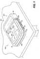
- FIG. 2illustrates a a clam-shell style handheld electonic device in an open configuration
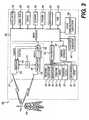
- FIG. 3is a block diagram representing a clam-shell style handheld electronic device interacting in a communication network
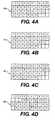
- FIG. 4Aillustrates an exemplary QWHRTY keyboard layout
- FIG. 4Billustrates an exemplary QWERTZ keyboard layout
- FIG. 4Cillustrates an exemplary AZERTY keyboard layout
- FIG. 4Dillustrates an exemplary Dvorak keyboard layout
- FIG. 5illustrates a QWERTY keyboard layout paired with a traditional ten-key keyboard
- FIG. 6illustrates ten digits comprising the numerals 0-9 arranged in a traditional, ITU Standard E.161 numeric telephone keypad layout, including the * and # keys flanking the 0 key;
- FIG. 7illustrates a traditional or standard phone key arrangement or layout according to the ITU Standard E.161 including both numerals and letters;
- FIG. 8illustrates front view of a clam-shell style handheld electronic device in a closed configuration
- FIG. 9illustrates a rear view of the clam-shell style handheld electronic device of FIG. 8 ;
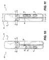
- FIG. 10illustrates a right side view of the clam-shell style handheld electronic device of FIG. 8 ;
- FIG. 11illustrates a left side view of the clam-shell style handheld electronic device of FIG. 8 ;
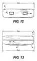
- FIG. 12illustrates a top plan view of the clam-shell style handheld electronic device of FIG. 8 ;
- FIG. 13illustrates a bottom plan view of the clam-shell style handheld electronic device of FIG. 8 ;
- FIG. 14illustrates a front view of a clam-shell style handheld electronic device in an open configuration
- FIG. 15illustrates a right side view of the clam-shell style handheld electronic device of FIG.14 in a resting orientation.
- Example embodiments that incorporate one or more aspects of the present disclosureare described and illustrated in the drawings. These illustrated examples are not intended to be a limitation on the present disclosure. For example, one or more aspects of the present disclosure can be utilized in other embodiments and even other types of devices. Moreover, certain terminology is used herein for convenience only and is not to be taken as a limitation on the disclosed subject matter. Still further, in the drawings, the same reference numerals are employed for designating the same elements.
- a usercan use a device as a telephone, a text entry point and as a web browser, quickly alternating between various modes. Because of these multiple roles for such devices and their prevalence of use, a user can wish to set a device down and not have a display screen face or point straight up, but instead will wish to for the display screen to substantially face the user.
- handheld devices 300examples include mobile stations, cellular telephones, wireless personal digital assistants (PDAs), two-way paging devices, and others.
- PDAspersonal digital assistants
- Various keyboardsare used with such devices and can be termed a full keyboard, a reduced-format keyboard, or phone key pad.
- the alphabetic charactersare singly associated with the plurality of physical keys.
- FIG. 1An example of a clam-shell style handheld electronic device 300 resting 603 on a flat surface in a closed configuration is shown in FIG. 1 .
- FIG. 2AAn example of the device 300 in an open configuration 601 within a user's hands is shown in FIG. 2A .
- FIG. 2BAn example of the device 300 in an open configuration 601 resting on a surface is shown in FIG. 2B . It is to be understood that all figures in the present disclosure are exemplary only, and those persons skilled in the art will appreciate the additional elements and modifications necessary to make the device 300 work in particular network environments.
- the handheld electronic device 300can be configured to cooperate with a wireless network as illustrated in FIG. 3 . It is contemplated that communication by the handheld electronic device 300 with the wireless network 319 can be any type of communication that both the wireless network 319 and handheld device 300 are enabled to transmit, receive and process. In general, these can be classified as voice and data. Voice communication is communication in which signals for audible sounds are transmitted by the handheld device 300 through the conummication network 319. Data is all other types of communication that the handheld device 300 is capable of performing within the constraints of the network 319 as depicted in FIG. 3 .
- the handheld electronic devices 300 in the block diagram of FIG. 3includes a microprocessor 338 that controls the operation of the device 300.
- a communication subsystem 311performs all communication transmission and reception with the wireless network 319.
- the microprocessor 338further connects with an auxiliary input/output (I/O) subsystem 328, a serial port (preferably a Universal Serial Bus port) 330, a display 322, a keyboard 650, a speaker 334, a microphone 336, random access memory (RAM) 326, and flash memory 324.
- I/Oauxiliary input/output
- serial portpreferably a Universal Serial Bus port
- display 322a keyboard 650
- speaker 334a speaker 334
- microphone 336random access memory
- flash memory 324random access memory
- An example of a communication subsystem 340is that of a short range communication system such as BLUETOOTH® communication module or a Wi-Fi communication module (a communication module in compliance with IEEE 802.11b) and associated circuits and components. Additionally, the microprocessor 338 is able to perform operating system functions and can enable execution of software applications on the handheld electronic device 300.
- a short range communication systemsuch as BLUETOOTH® communication module or a Wi-Fi communication module (a communication module in compliance with IEEE 802.11b) and associated circuits and components.
- the microprocessor 338is able to perform operating system functions and can enable execution of software applications on the handheld electronic device 300.
- the flash memory 324is enabled to provide a storage location for the operating system 357, device programs 358, and data.
- the operating system 357is generally configured to manage other application programs 358 that are also stored in memory 324 and executable on the processor 338.
- the operating system 357honors requests for services made by application programs 358 through predefined application program 358 interfaces. More specifically, the operating system 337 typically determines the order in which multiple applications 358 are executed on the processor 338 and the execution time allotted for each application 358, manages the sharing of memory 324 among multiple applications 358, handles input and output to and from other device subsystems 342.
- a user interfacecan include the keyboard 650 and display screen 322.
- the operating system 357is stored in flash memory 324, the operating system 357 in other embodiments is stored in read-only memory (ROM) or similar storage element (not shown).
- ROMread-only memory
- the operating system 357, device application 358 or parts thereofcan be loaded in RAM 326 or other volatile memory.
- the flash memory 324can contain programs/applications 358 for execution on the handheld device 300 including an address book 352, a personal information manager (PIM) 354, and the device state 350. Furthermore, programs 358 and other information 356 including data can be segregated upon storage in the flash memory 324 of the handheld device 300.
- PIMpersonal information manager
- the electronic device 300When the electronic device 300 is enabled for two-way communication within the wireless communication network 319 as depicted in FIG. 3 , it can send and receive signals from a mobile communication service.
- Examples of communication systems enabled for two-way communicationinclude, but are not limited to, the General Packet Radio Service (GPRS) network, the Universal Mobile Telecommunication Service (UMTS) network, the Enhanced Data for Global Evolution (EDGE) network, the Code Division Multiple Access (CDMA) network, High-Speed Packet Access (HSPA) networks, Universal Mobile Telecommunication Service Time Division Duplexing (UMTS-TDD), Ultra Mobile Broadband (UMB) networks, Worldwide Interoperability for Microwave Access (WiMAX), and other networks that can be used for data and voice, or just data or voice.
- GPRSGeneral Packet Radio Service
- UMTSUniversal Mobile Telecommunication Service
- EDGEEnhanced Data for Global Evolution
- CDMACode Division Multiple Access
- UMTS-TDDUniversal Mobile Telecommunication Service Time Division Duplexing
- the electronic device 300can require a unique identifier to enable the electronic device 300 to transmit and receive signals from the communication network 319. Other systems can not require such identifying information.
- GPRS, UMTS, and EDGEuse a Subscriber Identity Module (SIM) in order to allow communication with the communication network 319.
- SIMSubscriber Identity Module
- RUIMRemovable Identity Module
- the RUIM and SIM cardcan be used in multiple different electronic devices 300.
- the electronic device 300can be able to operate some features without a SIM/RUIM card, but it will not be able to communicate with the network 319.
- a SIM/RUIM interface 344 located within the electronic device 300allows for removal or insertion of a SIM/RUIM card (not shown).
- the SIM/RUIM cardfeatures memory and holds key configurations 351, and other information 353 such as identification and subscriber related information. With a properly enabled electronic device 300, two-way communication between the electronic device 300 and communication network 319 is possible.
- the handheld electronic device 300When equipped for two-way communication, the handheld electronic device 300 also features a communication subsystem 311 as indicated in FIG. 3 .
- the communication subsystem 311can modified so that it can support the operational needs of the handheld device 300.
- the subsystem 311includes a transmitter 314 and receiver 312 including the associated antenna or antennae 316, 318 as described above, local oscillators (LOs) 313, and a proccessing module 320 which in the presently described exemplary embodiment is a digital signal processor (DSP) 320.
- DSPdigital signal processor
- the two-way communication enabled handheld device 300is able to both transmit and receive information from the communication network 319.
- the transfer of communicationcan be to and from the handheld device 300.
- the handheld device 300 in the presently described exemplary embodimentis equipped with an integral or internal antenna 318 for transmitting signals to the communication network 319.
- the handheld electronic device 300 in the presently described exemplary embodimentcan be equipped with another antenna 316 for receiving communication from the communication network 319.
- These antennae 316, 318 in another exemplary embodimentcan be combined into a single antenna (not shown).
- the antenna or antennae 316, 318 in another embodimentcould be externally mounted on the handheld device 300.
- some applicationswhich can depend on data transfer data include email, address book entries and calendars.
- synchronization with home-based versions on the applicationscan be critical for either or both of their long term and short term utility.
- emailsare often time sensitive, so substantially real time synchronization is highly desirable.
- Address book entrieson the other hand, can be usually updated less frequently without inconvenience. Therefore, the utility of the handheld device 300 can be enhanced when connectable within a communication system, and particularly when connectable on a wireless basis in a network 319 in which voice, text messaging, and other data transfer are accommodated.
- auxiliary I/O subsystemscan include external display devices and externally connected keyboards (not shown). While the above examples have been provided in relation to the auxiliary I/O subsystem 328, other subsystems capable of providing input or receiving output from the handheld device 300 are considered within the scope of this disclosure.
- the handheld electronic device 300 as described abovecan be the clam-shell device 300 as illustrated in FIGS. 1-2 , and 8-15 .
- FIG. 1the clam-shell style handheld device 300 is in a closed configuration 600 in a resting orientation 603 and several features of the depicted embodiment are present.
- a microphone hole 860is visible on the keyboard housing 90.
- Visible on the back of the display housing 95are a display screen 854, a camera 851 and flash 852.
- one of the programmable buttons 105 on the keyboard housing 90 and volume control buttons 100 alongsideOne can also see two of the hinge-end covers 900 which cover the ends of one or more spring assemblies 750 that run through the interconnector 80 and into the display housing 95 and keyboard housing 90.
- FIG. 2Ashows an embodiment of the clam-shell style handheld electronic device 300 in an open configuration 601 being held in the hands of a user, ready for thumb activation of the keyboard 650.
- FIG. 2Bshows an embodiment of the handheld electronic device 300 in a resting configuration 603 on a flat surface.
- the receiver 895is above the display screen 322 on the display housing 95.
- Beside the receiver 895is a light emitting diode 896, and beneath is a display screen 322 on the interior side of the display screen housing 320.
- Breath the display screen 322is a navigational tool 327, which in the illustrated embodiment comprises a trackball assembly 321.
- the trackball assembly 321is located on the interior of the dual-hinged interconnector 80. Note in FIG.
- FIG. 2Bthat the trackball assembly 321 can be predominantly housed within the dual-hinged interconnector 80 and that a portion of the trackball assembly 321 is exposed at the interior surface 70 of said dual-hinged interconnector 80 in the open configuration 601 of the device 300.
- Beneath this "navigation row" 70is a keyboard 650.
- the keyboard 650rests on the interior side of the keyboard housing 640.
- the keyboard 650could comprise various alphanumeric keys 630 having any of the layouts shown by FIGS. 4-7 , or others.
- volume control keys 100for controlling speaker volume
- a user programmable button 105are visible on the outer left side of the keyboard housing 90
- other keyscan be placed along the side of the handheld device 300 to function as escape keys, volume control keys 100, scrolling keys, power switches, or user programmable keys 105, 120, and can likewise be programmed accordingly.
- the angle A 1 between the display housing 95 and the keyboard housing 90is adjustable at the interior side of the dual-hinged interconnector 80.
- FIGS. 2A and 2Bindicia, they could be arranged according to standard layouts as in FIG. 4 which shows the four possible keyboard 650 configurations, the QWERTY 44a, the QWERTZ 44b, the AZERTY 44c and the DVORAK 44d, or as in FIG. 5 which illustrates a QWERTY keyboard layout paired with a traditional ten-key keypad.
- the keys 630could also have layouts like those shown in FIGS. 6 and 7 , the last of which is ITU compliant.
- FIG. 6illustrates a keypad comprising the numerals 0-9 arranged in a traditional, ITU Standard E.16 numeric telephone keypad layout, including the * and # keys flanking the 0 key.
- FIG. 7illustrates a traditional or standard phone key arrangement or layout according to the ITU Standard E.161.
- the keyboard 650as shown in FIG. 2A and FIG. 2B for example, can be further provided with each of such layouts.
- One of the important aspects of the handheld electronic device 300 to which this disclosure is directedis its size. While some users will grasp the handheld device 300 in both hands when entering text as in FIG. 2A , it is also possible for users to cradle the handheld device 300 in one hand in such a manner that input and control over the handheld device 300 can be effected using the thumb of the same hand in which the handheld device 300 is held. However, it is appreciated that additional control can be effected by using both hands. As a handheld device 300 that is easy to grasp and desirably pocketable, the size of the handheld device 300 must be kept commensurately small. Of the device's dimensions, limiting its width is important for the purpose of assuring cradleability in a user's hand.
- the dual-hinged interconnector 80gives an increase in surface area and a protruding surface to grasp as well.
- the extended nature of the dual-hinged interconnector 80allows the clam-shell style handheld electronic device 300 to be held between the fingers of both hands.
- the interconnectorcan act as a handle of sorts.
- this configurationenhances stability and hence makes thumb activation of the keys on keyboard housing 640.
- the small size of the handheld device 300can be a drawback in that there is limited exterior surface area for the inclusion of user input and device output features. This is especially true for the "prime real estate" on the face of the keyboard housing 640 of the handheld device 300 in the open configuration 601.
- the display screen 322is located above a keyboard 650 that is utilized for data entry into the handheld device 300 by the user, and above a navigation tool 327 which is located on the interior surface of the dual-hinged interconnector. If the screen 322 is provided below the keyboard 650, a problem occurs in that viewing the screen 322 is inhibited when the user is inputting data using the keyboard 650. Therefore, in the embodiment shown in FIG.
- the display screen 322is above the navigation row 70 and keyboard 650, thereby solving the problem by assuring that the hands and fingers do not block the view of the screen 322 during data entry periods.
- This propertyis enhanced by the fact that the angle between the interior surface of the keyboard housing 640 and the interconnector 80, and the angle between the interconnector 80 and the display face 320 can each take separate values, and thus more positional options exist for the user.
- FIG. 2BAnother positional option for the user is to set the device down 300 temporarily, as in FIG. 2B (and also FIG. 15 ). If the user places the device on a flat surface a user can derive a benefit from being able to view the display screen 322 without having to lift the device 300 by hand.
- the dual-hinged interconnector 80can act as a stand which props up the display housing 95. Because they are connected via hinges, the angle A 1 between the display housing 95 and the keyboard housing 90, the angle A 2 between the back of the interconnector 81 and the display housing, and the angle A 3 between the interconnector 80 and the keyboard housing 90 are all adjustable. This adjustability, coupled with the stand action of the interconnector, 80 means that a user will be able to adjust the display screen 322 for maintenance of visual contact while the device 300 is in a resting orientation 303.
- FIG. 8shows the front of an embodiment of the clam-shell style handheld electronic device 300 in a closed configuration.
- a display screen 322 and a keyboard 650can be wholly or partially covered.
- the device 300can be equipped with an external mirror (not shown), a camera 851, a flash 852 for use in conjunction therewith, as well as a light emitting diode 853.
- the dual-hinged interconnector 80has a length L 3 which is greater than at least twenty percent of the length of the display housing L 1 . This allows for the interconnector 80 to act as both a stand and a handle as set forth previously.
- FIG. 9shows the rear or back of an embodiment of the device 300 in a closed configuration 600.
- a first side 81 of the dual-hinged interconnector 80is shown in a mutually accommodating relationship with the keyboard housing 90.
- Two charge contacts 807are shown towards the lower portion of keyboard housing 90.
- the keyboard housing 90can be seen to have a substantially square profile 800. As will be appreciated by those in the art, while a particular rectangular shape is shown for the handheld electronic device 300, others are possible while still falling within the present disclosure.
- the dual-hinged interconnector 80has a length L3 greater than at least twenty percent of a length L1 of the longer of the display housing 95 and the keyboard housings 90, and the lengthwise longitudinal axes of each of the display housing 95 and the keyboard housings 90 and dual-hitiged interconnector 80 are shown oriented substantially parallel, one to the others.
- the dual-hinged interconnector 80 or the display housing 95 or keyboard housing 90could be constructed in various proportions within this disclosure.
- FIG. 10A closed configuration 600 from the right side is also shown FIG. 10 .
- the device 300has multiple input and output faculties, even when in the closed config-umtion 600.
- a programmable key 120, a universal serial bus port 874 and a headset jack 875are shown on the exterior of the device 300 on the display housing.
- the programmable keys of the device 105, 120can be programmed to have multiple functions, allowing the keys to activate a camera, act as an alternate mute button, a function caned button, among other things.
- some portion of the keyboard 650can be seen between the keyboard housing 90 and display housing 95.
- the device 300could be so configured so as to completely conceal the keyboard 650 when viewed from the same side as in FIG. 10 while still coming within this disclosure.
- the dual-hinged interconnector 80can be seen between and above the hinge-end covers 900 in the illustrated example.
- the thickness of the interconnector T Tis equal to the combined thickness of the display housing 95 and the keyboard housing 90.
- the connectorscould be located on the sides of the interconnector 80 closest to the housings 95, 90 and parallel to the lengthwise axis, or on the sides which are closest to the housings 95, 90 but perpendicular to said axis.
- FIG. 11The other side view of the device 300 in a closed configuration 600 is shown in FIG. 11 .
- the volume buttons or keys 100 in the keyboard housing 90are situated next to a user-programmable key 105.
- the volume buttons or keyscan be configured so as to adjust the speaker (not shown) volume when the device 300 is used a telephone or to adjust the volume of the audio output associated with other functionalities.
- FIG. 11shows the dual-hinged interconnector 80 between and above two hinge-end covers 900.
- still other input and output optionscan be provided on the exterior of the device 300.
- handheld electronic device 300might be more or less oblong when closed 600, the sides could be fashioned to be somewhat arcuate, thus giving the device a near oval shape.
- FIG. 12The top of an embodiment of the device 300 in a closed configuration 600 is depicted in FIG, 12 .
- a mute/suspend key S80is shown on the left side of the exterior of the dual-hinged interconnector 80 and a speaker phone button 890 is on the right.
- Such locationsare examples only, and other possibilities exist within the present disclosure.
- other keys or buttonscan be located on the dual-hinged interconnector 80 which can take various shapes.
- a spring assembly(not shown) which runs through interconnector 80 to the binge-end covers 900.
- FIGS. 12 and 13show an embodiment wherein the dual-hinged miet-connector 80 is of a width W Y which is substantially equal to the width of the display housing W X1 and the width of the keyboard housing W X2 .
- W Ywidth
- the widths mentionedcould range between six and nine centimeters. Making the handheld electronic device 300 wider than nine inches would probably be undesirable due to a loss in convenience of storage-it would not fit in the average pocket or hand.
- FIG. 13The compact nature of the device 300, which is at least in part made possible by the dual-hinged interconnector 80, is shown in FIG. 13 .
- the thinness of the device 300can be seen in FIG. 13 insofar as the thickness of the dual-hinged interconnector T T in FIG. 12 is the same as the sum of the thickness of the keyboard housing T2 and the display housing T3, these thicknesses being measured in a direction substantially perpendicular the lengthwise axis of the display housing L X1 and the lengthwise axis of the keyboard housing L X2 when the device 300 is in a resting orientation 603 while closed 600. It is contemplated that the desired value for the total thickness T T of the device will fall in a range of about one to two centimeters (though other values are of course possible within this disclosure).
- FIG. 14shows the device 300 in an open configuration 601.
- maintenance of a visual line of sight with the display screen 322can be desirable when the user places the device 300 on a flat surface such as a desk or table.
- a dual-hinged interconnector 80 containing a spring assembly(not shown) is disclosed which will bias the interior surface of the display housing 320 at a suitable angle Al with the interior surface of the keyboard housing 640. As shown in FIG.
- the interior face of the keyboard housing 640includes a keyboard 650 with a plurality of keys that can be of a physical nature such as actuable buttons, or they can be of a software nature, typically constituted by virtual representations of physical keys on a display screen 322 (referred to herein as "virtual keys").
- virtual keystypically constituted by virtual representations of physical keys on a display screen 322
- the physical keyboard illustratedcould be replaced with a second display configured for touch engagement.
- the user inputcan be provided as a combination of the two types of keys.
- Each key of the plurality of keyshas at least one actuable action which can be the input of a character, a command or a function.
- charactersare contemplated to exemplarily include alphabetic letters, language symbols, numbers, punctuation, insignias, icons, pictures, and even a blank space.
- Input commands and functionscan include such things as delete, backspace, moving a cursor up, down, left or right, initiating an arithmetic function or command, initiating a command or function specific to an application program or feature in use, initiating a command or function programmed by the user and other such commands and functions that are well known to those persons skilled in the art.
- Specific keys or other types of input devicescan be used to navigate through the various applications and feature thereof. Further, depending on the program application 358 or feature in use, specific keys can be enabled or disabled.
- all or a portion of the plurality of keyscan have one or more indicia representing charader(s), command(s), and/or functions(s) displayed at their top surface and/or on the face of the area adjacent the respective key.
- the indicia of a key's functionis provided adjacent the key, the indicia can be printed on the device cover beside the key, or in the instance of keys located adjacent the display screen 322. Additionally, indicia for the key can be temporarily shown nearby the key on the display screen 322.
- physical and virtual keyscan be combined in many different ways.
- physical and virtual keyscould be combined such that the plurality of enabled keys for a particular application or feature of the handheld electronic device 300 is shown on the display screen 322 in the same configuration as the physical keys. Using this configuration, the user can select the appropriate physical key corresponding to what is shown on the display screen 322. Thus, the desired character, command or function is obtained by depressing the physical key corresponding to the character, command or function displayed at a corresponding position on the display screen 322, rather than touching the display screen 322.
- the clam-shell style handheld electronic device 300is configured to send and receive voice communications such as mobile telephone can and the functionality of the device can be afforded to the operator through designated keys.
- voice communicationssuch as mobile telephone can and the functionality of the device can be afforded to the operator through designated keys.
- two call keys 660, 670can be provided below the navigation row 70 (so-called because it includes the navigation tool 327) as shown in FIG. 14 which can facilitate telephone usage.
- One of the two call keysis a call initiation key 660, and the other is a call termination key 670
- the navigation row 70also includes another pair of keys 606, 608 that are located immediately adjacent to the navigation tool 327, with one flanking key on either side of the navigation tool 327.
- the flanking keys 606, 608can, for instance, constitute the menu keys 652, which include a menu call-up key 606 and an escape or back key 608.
- the menu call-up key 606is used to bring up a menu on the display screen 322 and the escape key 608 is used to return to the previous screen or previous menu selection.
- the functions of the can keys and the menu keyscan, of course, be provided by buttons that are located elsewhere on the handheld device 300, with different functions assigned to the flanking keys 606, 608.
- both the keyboard housing 90 and display housing 95can have an accommodation space 620 recessed into each housing that receives at least a portion of the trackball assembly 321 when the device 300 is in a closed configuration 600.
- the dual-hinged interconnectorprovides a mounting platform for the trackball assembly 321 and the keyboard housing 90 and display housing accommodate for a protruding trackball assembly 321 with the accommodation space 620 in the respective housing.
- the accommodation space 620might be provided only on the keyboard housing 90 or only on the display housing 95.
- FIG. 1illustrates a right side view of a clam-shell style handheld electronic device 300 in an open configuration 601.
- Two hinge covers 900 as well as a head set jack 875, universal serial bus port 874 and user programmable key 120are visible.
- Also visible in the example of FIG. 15is the top of a trackball assembly 321.
- the interior surface of the keyboard housing 640can be seen to be oriented at an obtuse angle Al to interior surface of the display housing 320.
- the dual-hinged interconnector 80can be configured such that the obtuse angle measures approximately 165 degrees. Alternately, the dual-hinged interconnector 80 could be set up for a 150 degree angle between the display 320 and the keyboard 650.
- the lengthwise longitudinal axis of the dual-hinged interconnector 80is shown oriented at an obtuse angle A2, A3 to the lengthwise longitudinal axis of the display and keyboard housings 95, 90 in the open configuration of the device 600.
Landscapes
- Engineering & Computer Science (AREA)
- Computer Hardware Design (AREA)
- Theoretical Computer Science (AREA)
- General Engineering & Computer Science (AREA)
- Human Computer Interaction (AREA)
- Physics & Mathematics (AREA)
- General Physics & Mathematics (AREA)
- Signal Processing (AREA)
- Mathematical Physics (AREA)
- Telephone Set Structure (AREA)
Description
- This disclosure, in a broad sense, is directed towards a clam-shell style handheld electronic device with wireless communication capabilities and towards the networks within which the device operates. The present disclosure further relates to a clam-shell style handheld electronic electronic device with an extended dual-hinged interconnector for pivotally connecting a keyboard housing to a display housing.
- With the proliferation of wireless communication systems, compatible. handheld electronic devices are becoming more prevalent, as well as advanced. Whereas in the past such handheld electronic devices were typically limited to either voice transmission (cell phones) or text transmission (pagers and PDAs), today's consumer often demands a multifunctional device capable of performing both types of transmissions, including even sending and receiving e-mail. Furthermore, these higher-performance devices can also be capable of sending and receiving other types of data including that which allows the viewing and use of Internet websites. These higher level functionalities necessarily require greater user interaction with the devices through included user interfaces (UIs) which may have originally been designed to accommodate making and receiving telephone cans and sending messages over a related Short Messaging Sendee (SMS). As might be expected, suppliers of such mobile electronic devices and the related service providers are anxious to meet these customer requirements, but the demands of these more advanced functionalities have in many circumstances rendered the traditional user interfaces unsatisfactory, a situation that has caused designers to have to improve the UIs through which users input information and control these sophisticated operations.
- Keyboards are used on many handheld devices, including telephones and mobile electronic devices. The size of keyboards has been reduced over the years, as newer, smaller devices have become popular, Cell phones, for example, are now sized to fit in one's pocket or the palm of the hand. As the size of the devices has decreased, it has become more important to utilize the entire keyboard surface as efficiently as possible. Thus, a need exists for a handheld electronic device which can be operated easily from a device perspective and a data entry perspective.
EP 1,653,713 A2 relates to a portable communication terminal having a camera module, a body section and a display section, the body section being connected to the camera module by a first hinge portion rotatable about a first hinge axis, the display section being connected to the camera module by a second hinge portion rotatable about a second hinge axis parallel to the first hinge axis, the second hinge portion being additionally rotatable about a third hinge axis perpendicular to the second hinge axis.- Exemplary methods and arrangements conducted and configured according to the advantageous solutions presented herein are depicted in the accompanying drawings wherein:
FIG. 1 illustrates a clam-shell style handheld electronic device in a closed configuration in a resting orientation;FIG. 2 illustrates a a clam-shell style handheld electonic device in an open configuration;FIG. 3 is a block diagram representing a clam-shell style handheld electronic device interacting in a communication network;FIG. 4A illustrates an exemplary QWHRTY keyboard layout;FIG. 4B illustrates an exemplary QWERTZ keyboard layout;FIG. 4C illustrates an exemplary AZERTY keyboard layout;FIG. 4D illustrates an exemplary Dvorak keyboard layout;FIG. 5 illustrates a QWERTY keyboard layout paired with a traditional ten-key keyboard;FIG. 6 illustrates ten digits comprising the numerals 0-9 arranged in a traditional, ITU Standard E.161 numeric telephone keypad layout, including the * and # keys flanking the 0 key;FIG. 7 illustrates a traditional or standard phone key arrangement or layout according to the ITU Standard E.161 including both numerals and letters;FIG. 8 illustrates front view of a clam-shell style handheld electronic device in a closed configuration;FIG. 9 illustrates a rear view of the clam-shell style handheld electronic device ofFIG. 8 ;FIG. 10 illustrates a right side view of the clam-shell style handheld electronic device ofFIG. 8 ;FIG. 11 illustrates a left side view of the clam-shell style handheld electronic device ofFIG. 8 ;FIG. 12 illustrates a top plan view of the clam-shell style handheld electronic device ofFIG. 8 ;FIG. 13 illustrates a bottom plan view of the clam-shell style handheld electronic device ofFIG. 8 ;FIG. 14 illustrates a front view of a clam-shell style handheld electronic device in an open configuration; andFIG. 15 illustrates a right side view of the clam-shell style handheld electronic device ofFIG.14 in a resting orientation.- Example embodiments that incorporate one or more aspects of the present disclosure are described and illustrated in the drawings. These illustrated examples are not intended to be a limitation on the present disclosure. For example, one or more aspects of the present disclosure can be utilized in other embodiments and even other types of devices. Moreover, certain terminology is used herein for convenience only and is not to be taken as a limitation on the disclosed subject matter. Still further, in the drawings, the same reference numerals are employed for designating the same elements.
- As the size of the devices has decreased it has also become more important to maintain the ease with which the user can utilize the keyboard. Advances in technology have allowed for such reductions of scale that ergonomic handleability can be of benefit. Additionally, as the size of devices has decreased it has allowed for use in more and more environments. A user can use a device as a telephone, a text entry point and as a web browser, quickly alternating between various modes. Because of these multiple roles for such devices and their prevalence of use, a user can wish to set a device down and not have a display screen face or point straight up, but instead will wish to for the display screen to substantially face the user.
- Examples of such
handheld devices 300 include mobile stations, cellular telephones, wireless personal digital assistants (PDAs), two-way paging devices, and others. Various keyboards are used with such devices and can be termed a full keyboard, a reduced-format keyboard, or phone key pad. In embodiments of ahandheld device 300 having a full keyboard, the alphabetic characters are singly associated with the plurality of physical keys. Thus, in an English-language keyboard of this configuration, there are at least 26 keys in the plurality, with one letter per alphabetic key. - An example of a clam-shell style handheld
electronic device 300 resting 603 on a flat surface in a closed configuration is shown inFIG. 1 . An example of thedevice 300 in anopen configuration 601 within a user's hands is shown inFIG. 2A . An example of thedevice 300 in anopen configuration 601 resting on a surface is shown inFIG. 2B . It is to be understood that all figures in the present disclosure are exemplary only, and those persons skilled in the art will appreciate the additional elements and modifications necessary to make thedevice 300 work in particular network environments. - The handheld
electronic device 300 can be configured to cooperate with a wireless network as illustrated inFIG. 3 . It is contemplated that communication by the handheldelectronic device 300 with thewireless network 319 can be any type of communication that both thewireless network 319 andhandheld device 300 are enabled to transmit, receive and process. In general, these can be classified as voice and data. Voice communication is communication in which signals for audible sounds are transmitted by thehandheld device 300 through theconummication network 319. Data is all other types of communication that thehandheld device 300 is capable of performing within the constraints of thenetwork 319 as depicted inFIG. 3 . - The handheld
electronic devices 300 in the block diagram ofFIG. 3 includes amicroprocessor 338 that controls the operation of thedevice 300. A communication subsystem 311 performs all communication transmission and reception with thewireless network 319. Themicroprocessor 338 further connects with an auxiliary input/output (I/O)subsystem 328, a serial port (preferably a Universal Serial Bus port) 330, adisplay 322, akeyboard 650, aspeaker 334, amicrophone 336, random access memory (RAM) 326, andflash memory 324.Other communication subsystems 340 andother device subsystems 342 are generally indicated as being functionally connected with themicroprocessor 338 as well. An example of acommunication subsystem 340 is that of a short range communication system such as BLUETOOTH® communication module or a Wi-Fi communication module (a communication module in compliance with IEEE 802.11b) and associated circuits and components. Additionally, themicroprocessor 338 is able to perform operating system functions and can enable execution of software applications on the handheldelectronic device 300. - In the exemplary configuration of
FIG. 3 , theflash memory 324 is enabled to provide a storage location for theoperating system 357,device programs 358, and data. Theoperating system 357 is generally configured to manageother application programs 358 that are also stored inmemory 324 and executable on theprocessor 338. Theoperating system 357 honors requests for services made byapplication programs 358 throughpredefined application program 358 interfaces. More specifically, the operating system 337 typically determines the order in whichmultiple applications 358 are executed on theprocessor 338 and the execution time allotted for eachapplication 358, manages the sharing ofmemory 324 amongmultiple applications 358, handles input and output to and fromother device subsystems 342. In addition, users can typically interact directly with theoperating system 357 through a user interface, which can include thekeyboard 650 anddisplay screen 322. While in an exemplary embodiment theoperating system 357 is stored inflash memory 324, theoperating system 357 in other embodiments is stored in read-only memory (ROM) or similar storage element (not shown). As those skilled in the art will appreciate, theoperating system 357,device application 358 or parts thereof can be loaded inRAM 326 or other volatile memory. - With further reference to
FIG. 3 , theflash memory 324 can contain programs/applications 358 for execution on thehandheld device 300 including anaddress book 352, a personal information manager (PIM) 354, and thedevice state 350. Furthermore,programs 358 andother information 356 including data can be segregated upon storage in theflash memory 324 of thehandheld device 300. - When the
electronic device 300 is enabled for two-way communication within thewireless communication network 319 as depicted inFIG. 3 , it can send and receive signals from a mobile communication service. Examples of communication systems enabled for two-way communication include, but are not limited to, the General Packet Radio Service (GPRS) network, the Universal Mobile Telecommunication Service (UMTS) network, the Enhanced Data for Global Evolution (EDGE) network, the Code Division Multiple Access (CDMA) network, High-Speed Packet Access (HSPA) networks, Universal Mobile Telecommunication Service Time Division Duplexing (UMTS-TDD), Ultra Mobile Broadband (UMB) networks, Worldwide Interoperability for Microwave Access (WiMAX), and other networks that can be used for data and voice, or just data or voice. For the systems listed above, theelectronic device 300 can require a unique identifier to enable theelectronic device 300 to transmit and receive signals from thecommunication network 319. Other systems can not require such identifying information. GPRS, UMTS, and EDGE use a Subscriber Identity Module (SIM) in order to allow communication with thecommunication network 319. Likewise, most CDMA systems use a Removable Identity Module (RUIM) in order to communicate with the CDMA network. The RUIM and SIM card can be used in multiple differentelectronic devices 300. Theelectronic device 300 can be able to operate some features without a SIM/RUIM card, but it will not be able to communicate with thenetwork 319. A SIM/RUIM interface 344 located within theelectronic device 300 allows for removal or insertion of a SIM/RUIM card (not shown). The SIM/RUIM card features memory and holdskey configurations 351, andother information 353 such as identification and subscriber related information. With a properly enabledelectronic device 300, two-way communication between theelectronic device 300 andcommunication network 319 is possible. - When equipped for two-way communication, the handheld
electronic device 300 also features a communication subsystem 311 as indicated inFIG. 3 . The communication subsystem 311 can modified so that it can support the operational needs of thehandheld device 300. As shown inFIG. 3 , the subsystem 311 includes atransmitter 314 andreceiver 312 including the associated antenna orantennae proccessing module 320 which in the presently described exemplary embodiment is a digital signal processor (DSP) 320. - If the handheld
electronic device 300 is enabled as described above, or thecommunication network 319 as shown inFIG. 3 does not require such enablement, the two-way communication enabledhandheld device 300 is able to both transmit and receive information from thecommunication network 319. The transfer of communication can be to and from thehandheld device 300. In order to communicate with thecommunication network 319, thehandheld device 300 in the presently described exemplary embodiment is equipped with an integral orinternal antenna 318 for transmitting signals to thecommunication network 319. Likewise the handheldelectronic device 300 in the presently described exemplary embodiment can be equipped with anotherantenna 316 for receiving communication from thecommunication network 319. Theseantennae antennae handheld device 300. - Additionally, some applications, such as shown in
FIG. 3 , which can depend on data transfer data include email, address book entries and calendars. For each such application, synchronization with home-based versions on the applications can be critical for either or both of their long term and short term utility. As an example, emails are often time sensitive, so substantially real time synchronization is highly desirable. Address book entries, on the other hand, can be usually updated less frequently without inconvenience. Therefore, the utility of thehandheld device 300 can be enhanced when connectable within a communication system, and particularly when connectable on a wireless basis in anetwork 319 in which voice, text messaging, and other data transfer are accommodated. The auxiliary I/O subsystem 328 ofFIG. 3 can take the form of a variety of different navigation tools (multi-directional or single-directional) such as anavigation tool 327 withtrackball assembly 321 as illustrated in the exemplary embodiment shown inFIG. 2 , or a thumbwheel, a navigation pad, a joystick, or the like (not shown). As will be developed more fully below, these navigation tools are located on the front surface of thehandheld device 300 when in anopen configuration 601 but can also be located on any exterior surface of thehandheld device 300. Other auxiliary I/O subsystems can include external display devices and externally connected keyboards (not shown). While the above examples have been provided in relation to the auxiliary I/O subsystem 328, other subsystems capable of providing input or receiving output from thehandheld device 300 are considered within the scope of this disclosure. - The handheld
electronic device 300 as described above can be the clam-shell device 300 as illustrated inFIGS. 1-2 , and8-15 .FIG. 1 the clam-shell stylehandheld device 300 is in aclosed configuration 600 in a restingorientation 603 and several features of the depicted embodiment are present. For example, amicrophone hole 860 is visible on thekeyboard housing 90. Visible on the back of thedisplay housing 95 are adisplay screen 854, acamera 851 andflash 852. Also visible is one of theprogrammable buttons 105 on thekeyboard housing 90 andvolume control buttons 100 alongside. One can also see two of the hinge-end covers 900 which cover the ends of one or more spring assemblies 750 that run through theinterconnector 80 and into thedisplay housing 95 andkeyboard housing 90. FIG. 2A shows an embodiment of the clam-shell style handheldelectronic device 300 in anopen configuration 601 being held in the hands of a user, ready for thumb activation of thekeyboard 650.FIG. 2B shows an embodiment of the handheldelectronic device 300 in a restingconfiguration 603 on a flat surface. InFIG. 2B thereceiver 895 is above thedisplay screen 322 on thedisplay housing 95. Beside thereceiver 895 is alight emitting diode 896, and beneath is adisplay screen 322 on the interior side of thedisplay screen housing 320. Breath thedisplay screen 322 is anavigational tool 327, which in the illustrated embodiment comprises atrackball assembly 321. Thetrackball assembly 321 is located on the interior of the dual-hingedinterconnector 80. Note inFIG. 2B that thetrackball assembly 321 can be predominantly housed within the dual-hingedinterconnector 80 and that a portion of thetrackball assembly 321 is exposed at theinterior surface 70 of said dual-hingedinterconnector 80 in theopen configuration 601 of thedevice 300. Beneath this "navigation row" 70 is akeyboard 650. Thekeyboard 650 rests on the interior side of thekeyboard housing 640. Those skilled in the art will appreciate that thekeyboard 650 could comprise variousalphanumeric keys 630 having any of the layouts shown byFIGS. 4-7 , or others.FIG. 2B showsvolume control keys 100, for controlling speaker volume, and a userprogrammable button 105 are visible on the outer left side of thekeyboard housing 90, Additionally, other keys can be placed along the side of thehandheld device 300 to function as escape keys,volume control keys 100, scrolling keys, power switches, or userprogrammable keys open configuration 601 shown, the angle A1 between thedisplay housing 95 and thekeyboard housing 90 is adjustable at the interior side of the dual-hingedinterconnector 80.- While the alphanumeric input keys in
FIGS. 2A and2B indicia, they could be arranged according to standard layouts as inFIG. 4 which shows the fourpossible keyboard 650 configurations, theQWERTY 44a, theQWERTZ 44b, the AZERTY 44c and the DVORAK 44d, or as inFIG. 5 which illustrates a QWERTY keyboard layout paired with a traditional ten-key keypad. Thekeys 630 could also have layouts like those shown inFIGS. 6 and 7 , the last of which is ITU compliant. The International Telecommunications Union ("ITU") has established phone standards for the arrangement of alphanumeric keys, entitled "Arrangement of Digits, Letters, and Symbols on Telephones and Other Devices That Can Be Used for Gaining Access to a Telephone Network." This standard is also known as ANSI TI.703-1995/1999 and ISO/IEC 9995-8:1994,FIG. 6 illustrates a keypad comprising the numerals 0-9 arranged in a traditional, ITU Standard E.16 numeric telephone keypad layout, including the * and # keys flanking the 0 key.FIG. 7 illustrates a traditional or standard phone key arrangement or layout according to the ITU Standard E.161. Again, thekeyboard 650, as shown inFIG. 2A andFIG. 2B for example, can be further provided with each of such layouts. - One of the important aspects of the handheld
electronic device 300 to which this disclosure is directed is its size. While some users will grasp thehandheld device 300 in both hands when entering text as inFIG. 2A , it is also possible for users to cradle thehandheld device 300 in one hand in such a manner that input and control over thehandheld device 300 can be effected using the thumb of the same hand in which thehandheld device 300 is held. However, it is appreciated that additional control can be effected by using both hands. As ahandheld device 300 that is easy to grasp and desirably pocketable, the size of thehandheld device 300 must be kept commensurately small. Of the device's dimensions, limiting its width is important for the purpose of assuring cradleability in a user's hand. - However, some users can find it difficult to operate because of the reduced size. The dual-hinged
interconnector 80 gives an increase in surface area and a protruding surface to grasp as well. The extended nature of the dual-hingedinterconnector 80 allows the clam-shell style handheldelectronic device 300 to be held between the fingers of both hands. Thus, the interconnector can act as a handle of sorts. Moreover, this configuration enhances stability and hence makes thumb activation of the keys onkeyboard housing 640. - Additionally, the small size of the
handheld device 300 can be a drawback in that there is limited exterior surface area for the inclusion of user input and device output features. This is especially true for the "prime real estate" on the face of thekeyboard housing 640 of thehandheld device 300 in theopen configuration 601. Furthermore, as shown in the embodiment ofFIG. 2A , thedisplay screen 322 is located above akeyboard 650 that is utilized for data entry into thehandheld device 300 by the user, and above anavigation tool 327 which is located on the interior surface of the dual-hinged interconnector. If thescreen 322 is provided below thekeyboard 650, a problem occurs in that viewing thescreen 322 is inhibited when the user is inputting data using thekeyboard 650. Therefore, in the embodiment shown inFIG. 2B , thedisplay screen 322 is above thenavigation row 70 andkeyboard 650, thereby solving the problem by assuring that the hands and fingers do not block the view of thescreen 322 during data entry periods. This property is enhanced by the fact that the angle between the interior surface of thekeyboard housing 640 and theinterconnector 80, and the angle between the interconnector 80 and thedisplay face 320 can each take separate values, and thus more positional options exist for the user. - Another positional option for the user is to set the device down 300 temporarily, as in
FIG. 2B (and alsoFIG. 15 ). If the user places the device on a flat surface a user can derive a benefit from being able to view thedisplay screen 322 without having to lift thedevice 300 by hand. As can be seen fromFIG. 2B , the dual-hingedinterconnector 80 can act as a stand which props up thedisplay housing 95. Because they are connected via hinges, the angle A1 between thedisplay housing 95 and thekeyboard housing 90, the angle A2 between the back of theinterconnector 81 and the display housing, and the angle A3 between the interconnector 80 and thekeyboard housing 90 are all adjustable. This adjustability, coupled with the stand action of the interconnector, 80 means that a user will be able to adjust thedisplay screen 322 for maintenance of visual contact while thedevice 300 is in a resting orientation 303. FIG. 8 shows the front of an embodiment of the clam-shell style handheldelectronic device 300 in a closed configuration. In a closed configuration 600 adisplay screen 322 and akeyboard 650 can be wholly or partially covered. Thedevice 300 can be equipped with an external mirror (not shown), acamera 851, aflash 852 for use in conjunction therewith, as well as a light emitting diode 853. Those skilled in the art will appreciate that these items could have different positions and still come within this disclosure. In the embodiment shownFIG. 8 the dual-hingedinterconnector 80 has a length L3 which is greater than at least twenty percent of the length of the display housing L1. This allows for the interconnector 80 to act as both a stand and a handle as set forth previously.FIG. 9 shows the rear or back of an embodiment of thedevice 300 in aclosed configuration 600. Afirst side 81 of the dual-hingedinterconnector 80 is shown in a mutually accommodating relationship with thekeyboard housing 90. Two charge contacts 807 are shown towards the lower portion ofkeyboard housing 90. Thekeyboard housing 90 can be seen to have a substantially square profile 800. As will be appreciated by those in the art, while a particular rectangular shape is shown for the handheldelectronic device 300, others are possible while still falling within the present disclosure. In the embodiment shown, the dual-hingedinterconnector 80 has a length L3 greater than at least twenty percent of a length L1 of the longer of thedisplay housing 95 and thekeyboard housings 90, and the lengthwise longitudinal axes of each of thedisplay housing 95 and thekeyboard housings 90 and dual-hitigedinterconnector 80 are shown oriented substantially parallel, one to the others. However, those skilled in the art will appreciate that the dual-hingedinterconnector 80 or thedisplay housing 95 orkeyboard housing 90 could be constructed in various proportions within this disclosure.- A
closed configuration 600 from the right side is also shownFIG. 10 . Although it is compact, thedevice 300 has multiple input and output faculties, even when in the closed config-umtion 600. For example, aprogrammable key 120, a universalserial bus port 874 and aheadset jack 875 are shown on the exterior of thedevice 300 on the display housing. Those skilled in the art will appreciate that the programmable keys of thedevice FIG, 10 , some portion of thekeyboard 650 can be seen between thekeyboard housing 90 anddisplay housing 95. In another possible embodiment thedevice 300 could be so configured so as to completely conceal thekeyboard 650 when viewed from the same side as inFIG. 10 while still coming within this disclosure. Also, the dual-hingedinterconnector 80 can be seen between and above the hinge-end covers 900 in the illustrated example. In the embodiment pictured in HIG. 10, the thickness of the interconnector TT is equal to the combined thickness of thedisplay housing 95 and thekeyboard housing 90. The connectors could be located on the sides of the interconnector 80 closest to thehousings housings - The other side view of the
device 300 in aclosed configuration 600 is shown inFIG. 11 . Even though the embodiment is streamlined and compact, multiple input and output options exist. For example, in the embodiment ofFIG. 11 , the volume buttons orkeys 100 in thekeyboard housing 90 are situated next to a user-programmable key 105. The volume buttons or keys can be configured so as to adjust the speaker (not shown) volume when thedevice 300 is used a telephone or to adjust the volume of the audio output associated with other functionalities.FIG. 11 shows the dual-hingedinterconnector 80 between and above two hinge-end covers 900. As will be described further herein, still other input and output options can be provided on the exterior of thedevice 300. Again, as will be appreciated by those in the art, while a particular shape is shown, others are possible while still falling within the present disclosure, for example handheldelectronic device 300 might be more or less oblong when closed 600, the sides could be fashioned to be somewhat arcuate, thus giving the device a near oval shape. - The top of an embodiment of the
device 300 in aclosed configuration 600 is depicted inFIG, 12 . A mute/suspend key S80 is shown on the left side of the exterior of the dual-hingedinterconnector 80 and aspeaker phone button 890 is on the right. Such locations are examples only, and other possibilities exist within the present disclosure. Also, other keys or buttons can be located on the dual-hingedinterconnector 80 which can take various shapes. Within the dual-hinged interconnector resides a spring assembly (not shown) which runs throughinterconnector 80 to the binge-end covers 900. - Both
FIGS. 12 and 13 show an embodiment wherein the dual-hinged miet-connector 80 is of a width WY which is substantially equal to the width of the display housing WX1 and the width of the keyboard housing WX2. Other embodiments having different widths are possible within this disclosure, For example, the widths mentioned could range between six and nine centimeters. Making the handheldelectronic device 300 wider than nine inches would probably be undesirable due to a loss in convenience of storage-it would not fit in the average pocket or hand. - The compact nature of the
device 300, which is at least in part made possible by the dual-hingedinterconnector 80, is shown inFIG. 13 . The thinness of thedevice 300 can be seen inFIG. 13 insofar as the thickness of the dual-hinged interconnector TT inFIG. 12 is the same as the sum of the thickness of the keyboard housing T2 and the display housing T3, these thicknesses being measured in a direction substantially perpendicular the lengthwise axis of the display housing LX1 and the lengthwise axis of the keyboard housing LX2 when thedevice 300 is in a restingorientation 603 while closed 600. It is contemplated that the desired value for the total thickness TT of the device will fall in a range of about one to two centimeters (though other values are of course possible within this disclosure). FIG. 14 shows thedevice 300 in anopen configuration 601. As set forth above, maintenance of a visual line of sight with thedisplay screen 322 can be desirable when the user places thedevice 300 on a flat surface such as a desk or table. As discussed previously, a dual-hingedinterconnector 80 containing a spring assembly (not shown) is disclosed which will bias the interior surface of thedisplay housing 320 at a suitable angle Al with the interior surface of thekeyboard housing 640. As shown inFIG. 14 , the interior face of thekeyboard housing 640 includes akeyboard 650 with a plurality of keys that can be of a physical nature such as actuable buttons, or they can be of a software nature, typically constituted by virtual representations of physical keys on a display screen 322 (referred to herein as "virtual keys"). In this instance the physical keyboard illustrated could be replaced with a second display configured for touch engagement. It is also contemplated that the user input can be provided as a combination of the two types of keys. Each key of the plurality of keys has at least one actuable action which can be the input of a character, a command or a function. In this context, "characters" are contemplated to exemplarily include alphabetic letters, language symbols, numbers, punctuation, insignias, icons, pictures, and even a blank space. Input commands and functions can include such things as delete, backspace, moving a cursor up, down, left or right, initiating an arithmetic function or command, initiating a command or function specific to an application program or feature in use, initiating a command or function programmed by the user and other such commands and functions that are well known to those persons skilled in the art. Specific keys or other types of input devices can be used to navigate through the various applications and feature thereof. Further, depending on theprogram application 358 or feature in use, specific keys can be enabled or disabled.- In the case of physical keys of the type shown in
FIG. 14 , all or a portion of the plurality of keys can have one or more indicia representing charader(s), command(s), and/or functions(s) displayed at their top surface and/or on the face of the area adjacent the respective key. In the instance where the indicia of a key's function is provided adjacent the key, the indicia can be printed on the device cover beside the key, or in the instance of keys located adjacent thedisplay screen 322. Additionally, indicia for the key can be temporarily shown nearby the key on thedisplay screen 322. As will be appreciated by those in the art, physical and virtual keys can be combined in many different ways. In one embodiment, physical and virtual keys could be combined such that the plurality of enabled keys for a particular application or feature of the handheldelectronic device 300 is shown on thedisplay screen 322 in the same configuration as the physical keys. Using this configuration, the user can select the appropriate physical key corresponding to what is shown on thedisplay screen 322. Thus, the desired character, command or function is obtained by depressing the physical key corresponding to the character, command or function displayed at a corresponding position on thedisplay screen 322, rather than touching thedisplay screen 322. - As made clear previously, the clam-shell style handheld
electronic device 300 is configured to send and receive voice communications such as mobile telephone can and the functionality of the device can be afforded to the operator through designated keys. For example, twocall keys FIG. 14 which can facilitate telephone usage. One of the two call keys is a call initiation key 660, and the other is acall termination key 670, Thenavigation row 70 also includes another pair ofkeys navigation tool 327, with one flanking key on either side of thenavigation tool 327. The flankingkeys key 606 and an escape or back key 608. The menu call-upkey 606 is used to bring up a menu on thedisplay screen 322 and theescape key 608 is used to return to the previous screen or previous menu selection. The functions of the can keys and the menu keys can, of course, be provided by buttons that are located elsewhere on thehandheld device 300, with different functions assigned to the flankingkeys - As shown in
FIG. 14 , both thekeyboard housing 90 anddisplay housing 95 can have anaccommodation space 620 recessed into each housing that receives at least a portion of thetrackball assembly 321 when thedevice 300 is in aclosed configuration 600. In this configuration, the dual-hinged interconnector provides a mounting platform for thetrackball assembly 321 and thekeyboard housing 90 and display housing accommodate for a protrudingtrackball assembly 321 with theaccommodation space 620 in the respective housing. In other embodiment, theaccommodation space 620 might be provided only on thekeyboard housing 90 or only on thedisplay housing 95. FIG. 1 illustrates a right side view of a clam-shell style handheldelectronic device 300 in anopen configuration 601. Two hinge covers 900 as well as a head setjack 875, universalserial bus port 874 and userprogrammable key 120 are visible. Also visible in the example ofFIG. 15 is the top of atrackball assembly 321. The interior surface of thekeyboard housing 640 can be seen to be oriented at an obtuse angle Al to interior surface of thedisplay housing 320. The dual-hingedinterconnector 80 can be configured such that the obtuse angle measures approximately 165 degrees. Alternately, the dual-hingedinterconnector 80 could be set up for a 150 degree angle between thedisplay 320 and thekeyboard 650. The lengthwise longitudinal axis of the dual-hingedinterconnector 80 is shown oriented at an obtuse angle A2, A3 to the lengthwise longitudinal axis of the display andkeyboard housings device 600.- As described above, those skilled in the art will recognize that other angle configurations are possible within the scope of the present disclosure.
- It will be understood that the foregoing description is that of certain embodiments and that various changes and modifications can be made thereto without deputing from the scope of this disclosure,
Claims (6)
- A clam-shell style handheld electronic device (300) transitionable between open and closed configurations (601, 600), said device (300) comprising:a display housing (95) pivotally coupled by a dual-hinged interconnector (80) to a keyboard housing (90), said display housing (95) having a display screen (322) located at an interior surface (320) thereof facing a keyboard (650) on an interior surface (640) of said keyboard housing (90) in the closed configuration of the device (600);said dual-hinged interconnector (80) having a thickness (TT) substantially equal to a combined thickness of said display and keyboard housings (95, 90) in the closed configuration of the device (600);said dual-hinged interconnector (80) having a length (L3) greater than at least twenty percent of a length (L1) of the longer of said display and keyboard housings (95, 90) and wherein lengthwise longitudinal axes of each of said display and keyboard housings (95, 90) and said dual-hinged interconnector (80) are oriented substantially parallel, one to the others, in the closed configuration of the device (600) such that said dual-hinged interconnector can act as a stand and a handle; said dual-hinged interconnector (80) further comprising a central portion;characterised in thatsaid dual-hinged interconnector (80) has a navigation tool (327) located at an interior surface of the central portion thereof in the closed configuration of the device (600) and the navigation tool (327) is predominantly housed within the dualhinged interconnector (80),
at least one of said display housing and said keyboard housing further having a recess into which each housing receives at least a portion of the navigation tool, andwherein said dual-hinged interconnector is coupled to each of said keyboard housing and display housing between a pair of hinge-end covers. - The clam-shell style handheld electronic device (300) as recited in claim 1, wherein said display and keyboard housings (95, 90) are oriented at an obtuse angle (A1) to one another in the open configuration (601) and the lengthwise longitudinal axis of said dual-hinged interconnector (80) is oriented at an obtuse angle (A2, A3) to the lengthwise longitudinal axis of at least one of said display and keyboard housings (95, 90) in the open configuration of the device (600).
- The clam-shell style handheld electronic device (300)as recited in claim 2, wherein the lengthwise longitudinal axis of said dual-hinged interconnector (80) is oriented at an obtuse angle (A2, A3) to both of the lengthwise longitudinal axes of said display and keyboard housings (LX1, LX2) in the open configuration of the device (600).
- The clam-shell style handheld electronic device (300) as recited in claim 3, wherein said dual-hinged interconnector (80) has a width (WY) substantially equal to a width of each of said display and keyboard housings (WX1, WX2), said widths measured in a direction substantially perpendicular to said lengthwise axes (LX1, LX2) in the closed configuration of the device (600).
- The clam-shell style handheld electronic device (300) as recited in claim 4, wherein said thicknesses (TT) are measured in a direction substantially perpendicular to said lengthwise axes (LX1, LX2) in the closed configuration of the device (600).
- The clam-shell style handheld electronic device (300) as recited in claim 1, wherein said navigation device (300) is a trackball assembly (321) comprising a trackball, said trackball assembly (321) being predominantly housed within said dual-hinged interconnector (80) and a portion of said trackball being exposed at the interior surface of said dual-hinged interconnector (82) in the open configuration of the device (601).
Priority Applications (1)
| Application Number | Priority Date | Filing Date | Title |
|---|---|---|---|
| CA2686166ACA2686166C (en) | 2009-01-16 | 2009-11-20 | Handheld electronic device with extended dual-hinged interconnector |
Applications Claiming Priority (1)
| Application Number | Priority Date | Filing Date | Title |
|---|---|---|---|
| US12/016,570US8611971B2 (en) | 2008-01-18 | 2008-01-18 | Hinging interconnector for a clamshell handheld electronic communication device |
Publications (2)
| Publication Number | Publication Date |
|---|---|
| EP2081365A1 EP2081365A1 (en) | 2009-07-22 |
| EP2081365B1true EP2081365B1 (en) | 2013-10-16 |
Family
ID=40513523
Family Applications (1)
| Application Number | Title | Priority Date | Filing Date |
|---|---|---|---|
| EP09150797.0AActiveEP2081365B1 (en) | 2008-01-18 | 2009-01-16 | Handheld electronic device with extended dual-hinged interconnector |
Country Status (2)
| Country | Link |
|---|---|
| US (1) | US8611971B2 (en) |
| EP (1) | EP2081365B1 (en) |
Families Citing this family (6)
| Publication number | Priority date | Publication date | Assignee | Title |
|---|---|---|---|---|
| USD628970S1 (en)* | 2008-01-18 | 2010-12-14 | Research In Motion Limited | Handheld electronic communication device |
| USD612372S1 (en)* | 2008-12-23 | 2010-03-23 | Research In Motion Limited | Keypad |
| USD636384S1 (en)* | 2009-08-25 | 2011-04-19 | Research In Motion Limited | Keypad |
| USD750606S1 (en)* | 2013-08-01 | 2016-03-01 | Fu Ding Electronical Technology (Jiashan) Co., Ltd. | Keyboard for a mobile phone |
| KR102269779B1 (en)* | 2014-03-28 | 2021-06-28 | 삼성전자주식회사 | Method for displaying screen in electronic device and the electronic device |
| USD935427S1 (en)* | 2018-06-26 | 2021-11-09 | Sennheiser Electronic Gmbh & Co. Kg | Audio/video appliance for reproducing sounds or images |
Citations (1)
| Publication number | Priority date | Publication date | Assignee | Title |
|---|---|---|---|---|
| US20060034601A1 (en)* | 2003-04-23 | 2006-02-16 | Tage Andersson | Multi-function two panel electronic device with 360° relative motion |
Family Cites Families (49)
| Publication number | Priority date | Publication date | Assignee | Title |
|---|---|---|---|---|
| USD307012S (en)* | 1986-12-03 | 1990-04-03 | Ericsson Paging Systems B.V. | Radio pager |
| USD310237S (en)* | 1988-01-22 | 1990-08-28 | Canon Kabushiki Kaisha | Copier control device |
| US5185790A (en)* | 1991-03-28 | 1993-02-09 | Motorola, Inc. | Multiposition detenting hinge apparatus |
| US5537472A (en)* | 1995-03-09 | 1996-07-16 | At&T Corp. | Portable telephone with flip stand or hinged doors and having speaker therein |
| USD382820S (en)* | 1995-11-17 | 1997-08-26 | Idt International Limited | Timer |
| JP3844585B2 (en) | 1998-01-06 | 2006-11-15 | 松下電器産業株式会社 | Portable wireless communication device |
| US6118986A (en)* | 1998-01-16 | 2000-09-12 | Motorola, Inc. | Device for use with a user interface card |
| HK1047509B (en)* | 1999-05-06 | 2005-05-27 | 高通股份有限公司 | Detection of flip closure state of a flip phone |
| JP2002204297A (en)* | 2000-11-02 | 2002-07-19 | Sharp Corp | Portable information equipment |
| USD467891S1 (en)* | 2001-03-13 | 2002-12-31 | Matsushita Electric Industrial Co., Ltd. | Memory card player for audio |
| JP3726892B2 (en)* | 2001-10-15 | 2005-12-14 | ソニー株式会社 | Portable terminal device and display control program thereof |
| US6934568B2 (en)* | 2002-03-08 | 2005-08-23 | Motorola, Inc. | Extending hinged flip apparatus for a communication device |
| JP4170013B2 (en)* | 2002-04-18 | 2008-10-22 | 松下電器産業株式会社 | Electronics |
| US6775560B2 (en)* | 2002-05-31 | 2004-08-10 | Lavaflow, Llp | Cellular telephone having a touch screen user interface |
| JP2004007188A (en)* | 2002-05-31 | 2004-01-08 | Toshiba Corp | Electronics |
| USD484918S1 (en)* | 2002-08-01 | 2004-01-06 | Nintendo Co., Ltd. | Hand-held electronic game machine |
| US20040020012A1 (en) | 2002-08-02 | 2004-02-05 | Gupte Sheel A. | Self-contained hinge for flip-style device |
| JP2004147279A (en) | 2002-08-30 | 2004-05-20 | Fujitsu Ltd | Foldable electronics |
| JP2004293633A (en) | 2003-03-26 | 2004-10-21 | Nec Corp | Folding portable terminal |
| JP2004297417A (en)* | 2003-03-27 | 2004-10-21 | Sanyo Electric Co Ltd | Portable radio terminal |
| WO2004090355A1 (en) | 2003-04-03 | 2004-10-21 | Sugatsune Kogyo Co., Ltd. | Device case opening/closing device, and 2-axis hinge device |
| USD496636S1 (en)* | 2003-07-14 | 2004-09-28 | Motorola, Inc. | Communication device |
| US6831229B1 (en)* | 2003-09-11 | 2004-12-14 | Nokia Corporation | Hinge cover mechanism for folding casings with lift function |
| JP4311254B2 (en)* | 2004-03-31 | 2009-08-12 | 日本電気株式会社 | Portable electronic devices |
| USD539772S1 (en)* | 2004-05-05 | 2007-04-03 | Samsung Electronics Co., Ltd. | Portable telephone |
| USD499424S1 (en)* | 2004-05-06 | 2004-12-07 | Creative Technology Limited | Media player |
| USD507554S1 (en)* | 2004-07-27 | 2005-07-19 | Curitel Communications, Inc. | Cellular phone |
| CN100394763C (en)* | 2004-09-15 | 2008-06-11 | 索尼株式会社 | Input device |
| KR100735266B1 (en) | 2004-10-26 | 2007-07-03 | 삼성전자주식회사 | Mobile phone for multimedia |
| ATE472890T1 (en) | 2004-12-09 | 2010-07-15 | Lg Electronics Inc | HINGE JOINT AND MOBILE TERMINAL WHICH INCLUDE THIS |
| USD525230S1 (en)* | 2005-01-17 | 2006-07-18 | Samsung Electronics Co., Ltd. | Cellular phone |
| US9274551B2 (en)* | 2005-02-23 | 2016-03-01 | Zienon, Llc | Method and apparatus for data entry input |
| CA110817S (en)* | 2005-03-29 | 2006-05-23 | Bang & Olufsen As | Mobile phone |
| FI117312B (en)* | 2005-05-13 | 2006-08-31 | Nokia Corp | Hinge structure for electronic device e.g. mobile phone, has shield structure connected to hinge unit, and shielding back of device and moving in direction perpendicular to rotation axis |
| USD551200S1 (en)* | 2005-05-28 | 2007-09-18 | Motorola, Inc. | Communication device |
| USD549680S1 (en)* | 2005-06-22 | 2007-08-28 | Lg Electronics Inc. | Mobile phone |
| TWI264925B (en)* | 2005-07-05 | 2006-10-21 | Benq Corp | Portable electronic device |
| JP2007027806A (en)* | 2005-07-12 | 2007-02-01 | Hitachi Ltd | Portable terminal |
| USD566080S1 (en)* | 2005-08-18 | 2008-04-08 | Lg Electronics Inc. | Mobile phone |
| USD566671S1 (en)* | 2005-10-28 | 2008-04-15 | Samsung Electronics Co., Ltd. | Portable phone |
| USD570319S1 (en)* | 2006-02-10 | 2008-06-03 | Samsung Electronics Co., Ltd. | Portable phone for an earpiece |
| USD561719S1 (en)* | 2006-03-24 | 2008-02-12 | Lg Electronics Inc. | Cellular phone |
| TWD124792S1 (en)* | 2006-11-20 | 2008-09-11 | 三星電子股份有限公司 | Mobile phone |
| USD561723S1 (en)* | 2006-12-07 | 2008-02-12 | Samsung Electronics Co., Ltd. | Mobile phone |
| TWI388186B (en)* | 2007-05-22 | 2013-03-01 | Htc Corp | Communication device |
| USD571344S1 (en)* | 2007-08-24 | 2008-06-17 | Samsung Electronics Co., Ltd. | Portable phone |
| USD584268S1 (en)* | 2007-11-30 | 2009-01-06 | Samsung Electronics Co., Ltd. | Mobile phone |
| US20090186662A1 (en)* | 2008-01-18 | 2009-07-23 | Research In Motion Limited | Clamshell handheld electronic communication device with pivotally coupled interconnector |
| US8489157B2 (en)* | 2008-01-18 | 2013-07-16 | Research In Motion Limited | Handheld electronic device with extended dual-hinged interconnector |
- 2008
- 2008-01-18USUS12/016,570patent/US8611971B2/enactiveActive
- 2009
- 2009-01-16EPEP09150797.0Apatent/EP2081365B1/enactiveActive
Patent Citations (1)
| Publication number | Priority date | Publication date | Assignee | Title |
|---|---|---|---|---|
| US20060034601A1 (en)* | 2003-04-23 | 2006-02-16 | Tage Andersson | Multi-function two panel electronic device with 360° relative motion |
Also Published As
| Publication number | Publication date |
|---|---|
| US8611971B2 (en) | 2013-12-17 |
| EP2081365A1 (en) | 2009-07-22 |
| US20090186660A1 (en) | 2009-07-23 |
Similar Documents
| Publication | Publication Date | Title |
|---|---|---|
| US8489157B2 (en) | Handheld electronic device with extended dual-hinged interconnector | |
| US20090186662A1 (en) | Clamshell handheld electronic communication device with pivotally coupled interconnector | |
| US8154520B2 (en) | Handheld electronic communication device transitionable between compact and expanded configurations | |
| WO2008037054A1 (en) | Outwardly decreasing height keys for a handheld electronic device keyboard | |
| US8346294B2 (en) | Appearance adaptable keypad for a handheld communication device | |
| EP2081365B1 (en) | Handheld electronic device with extended dual-hinged interconnector | |
| US9148503B2 (en) | Differentiating a portion of a text message shown in a listing on a handheld communication device using an icon | |
| US9100470B2 (en) | Biasing component for raising and lowering a keyboard for a handheld communication device | |
| US8358267B2 (en) | Conjoined input keys adjacent a navigation tool on a handheld electronic device | |
| EP2275980B1 (en) | Message Address Characteristic Differentiation Method and Apparatus | |
| CA2705660C (en) | A biasing component for raising and lowering a keyboard for a handheld communication device | |
| CA2686166C (en) | Handheld electronic device with extended dual-hinged interconnector | |
| EP2081367A1 (en) | Clamshell handheld electronic, communication device with pivotally coupled interconnector | |
| CA2638872C (en) | Conjoined input keys adjacent a navigation tool on a handheld electronic device | |
| EP2006761B1 (en) | Appearance adaptable keypad for a handheld communication device | |
| US9385771B2 (en) | Release mechanism for a smart card | |
| EP2107764A1 (en) | Handheld electronic communication device transitionable between compact and expanded configurations | |
| CA2726069C (en) | Release mechanism for a smart card | |
| CA2686200A1 (en) | Clamshell handheld electronic communication device with pivotally coupled interconnector | |
| HK1133506A (en) | Handheld electronic communication device transitionable between compact and expanded configurations |
Legal Events
| Date | Code | Title | Description |
|---|---|---|---|
| PUAI | Public reference made under article 153(3) epc to a published international application that has entered the european phase | Free format text:ORIGINAL CODE: 0009012 | |
| 17P | Request for examination filed | Effective date:20090119 | |
| AK | Designated contracting states | Kind code of ref document:A1 Designated state(s):AT BE BG CH CY CZ DE DK EE ES FI FR GB GR HR HU IE IS IT LI LT LU LV MC MK MT NL NO PL PT RO SE SI SK TR | |
| AX | Request for extension of the european patent | Extension state:AL BA RS | |
| 17Q | First examination report despatched | Effective date:20100226 | |
| AKX | Designation fees paid | Designated state(s):AT BE BG CH CY CZ DE DK EE ES FI FR GB GR HR HU IE IS IT LI LT LU LV MC MK MT NL NO PL PT RO SE SI SK TR | |
| AXX | Extension fees paid | Extension state:RS Payment date:20090119 Extension state:BA Payment date:20090119 Extension state:AL Payment date:20090119 | |
| RIC1 | Information provided on ipc code assigned before grant | Ipc:H04M 1/02 20060101AFI20130319BHEP Ipc:G06F 1/16 20060101ALN20130319BHEP | |
| RIC1 | Information provided on ipc code assigned before grant | Ipc:G06F 1/16 20060101ALN20130404BHEP Ipc:H04M 1/02 20060101AFI20130404BHEP | |
| RIC1 | Information provided on ipc code assigned before grant | Ipc:G06F 1/16 20060101ALN20130411BHEP Ipc:H04M 1/02 20060101AFI20130411BHEP | |
| GRAP | Despatch of communication of intention to grant a patent | Free format text:ORIGINAL CODE: EPIDOSNIGR1 | |
| RIC1 | Information provided on ipc code assigned before grant | Ipc:G06F 1/16 20060101ALN20130419BHEP Ipc:H04M 1/02 20060101AFI20130419BHEP | |
| INTG | Intention to grant announced | Effective date:20130522 | |
| GRAS | Grant fee paid | Free format text:ORIGINAL CODE: EPIDOSNIGR3 | |
| RAP1 | Party data changed (applicant data changed or rights of an application transferred) | Owner name:BLACKBERRY LIMITED | |
| GRAA | (expected) grant | Free format text:ORIGINAL CODE: 0009210 | |
| AK | Designated contracting states | Kind code of ref document:B1 Designated state(s):AT BE BG CH CY CZ DE DK EE ES FI FR GB GR HR HU IE IS IT LI LT LU LV MC MK MT NL NO PL PT RO SE SI SK TR | |
| AX | Request for extension of the european patent | Extension state:AL BA RS | |
| REG | Reference to a national code | Ref country code:GB Ref legal event code:FG4D | |
| REG | Reference to a national code | Ref country code:CH Ref legal event code:EP | |
| REG | Reference to a national code | Ref country code:IE Ref legal event code:FG4D | |
| REG | Reference to a national code | Ref country code:AT Ref legal event code:REF Ref document number:636958 Country of ref document:AT Kind code of ref document:T Effective date:20131115 Ref country code:CH Ref legal event code:PCOW Free format text:NEW ADDRESS: 2200 UNIVERSITY AVENUE EAST, WATERLOO, ON N2K 0A7 (CA) | |
| RAP2 | Party data changed (patent owner data changed or rights of a patent transferred) | Owner name:BLACKBERRY LIMITED | |
| REG | Reference to a national code | Ref country code:DE Ref legal event code:R096 Ref document number:602009019423 Country of ref document:DE Effective date:20131212 | |
| REG | Reference to a national code | Ref country code:NL Ref legal event code:T3 | |
| REG | Reference to a national code | Ref country code:NL Ref legal event code:T3 | |
| REG | Reference to a national code | Ref country code:AT Ref legal event code:MK05 Ref document number:636958 Country of ref document:AT Kind code of ref document:T Effective date:20131016 | |
| REG | Reference to a national code | Ref country code:LT Ref legal event code:MG4D | |
| PG25 | Lapsed in a contracting state [announced via postgrant information from national office to epo] | Ref country code:BE Free format text:LAPSE BECAUSE OF FAILURE TO SUBMIT A TRANSLATION OF THE DESCRIPTION OR TO PAY THE FEE WITHIN THE PRESCRIBED TIME-LIMIT Effective date:20131016 Ref country code:SE Free format text:LAPSE BECAUSE OF FAILURE TO SUBMIT A TRANSLATION OF THE DESCRIPTION OR TO PAY THE FEE WITHIN THE PRESCRIBED TIME-LIMIT Effective date:20131016 Ref country code:HR Free format text:LAPSE BECAUSE OF FAILURE TO SUBMIT A TRANSLATION OF THE DESCRIPTION OR TO PAY THE FEE WITHIN THE PRESCRIBED TIME-LIMIT Effective date:20131016 Ref country code:FI Free format text:LAPSE BECAUSE OF FAILURE TO SUBMIT A TRANSLATION OF THE DESCRIPTION OR TO PAY THE FEE WITHIN THE PRESCRIBED TIME-LIMIT Effective date:20131016 Ref country code:IS Free format text:LAPSE BECAUSE OF FAILURE TO SUBMIT A TRANSLATION OF THE DESCRIPTION OR TO PAY THE FEE WITHIN THE PRESCRIBED TIME-LIMIT Effective date:20140216 Ref country code:LT Free format text:LAPSE BECAUSE OF FAILURE TO SUBMIT A TRANSLATION OF THE DESCRIPTION OR TO PAY THE FEE WITHIN THE PRESCRIBED TIME-LIMIT Effective date:20131016 Ref country code:NO Free format text:LAPSE BECAUSE OF FAILURE TO SUBMIT A TRANSLATION OF THE DESCRIPTION OR TO PAY THE FEE WITHIN THE PRESCRIBED TIME-LIMIT Effective date:20140116 | |
| PG25 | Lapsed in a contracting state [announced via postgrant information from national office to epo] | Ref country code:AT Free format text:LAPSE BECAUSE OF FAILURE TO SUBMIT A TRANSLATION OF THE DESCRIPTION OR TO PAY THE FEE WITHIN THE PRESCRIBED TIME-LIMIT Effective date:20131016 Ref country code:CY Free format text:LAPSE BECAUSE OF FAILURE TO SUBMIT A TRANSLATION OF THE DESCRIPTION OR TO PAY THE FEE WITHIN THE PRESCRIBED TIME-LIMIT Effective date:20131016 Ref country code:LV Free format text:LAPSE BECAUSE OF FAILURE TO SUBMIT A TRANSLATION OF THE DESCRIPTION OR TO PAY THE FEE WITHIN THE PRESCRIBED TIME-LIMIT Effective date:20131016 Ref country code:ES Free format text:LAPSE BECAUSE OF FAILURE TO SUBMIT A TRANSLATION OF THE DESCRIPTION OR TO PAY THE FEE WITHIN THE PRESCRIBED TIME-LIMIT Effective date:20131016 | |
| PG25 | Lapsed in a contracting state [announced via postgrant information from national office to epo] | Ref country code:PT Free format text:LAPSE BECAUSE OF FAILURE TO SUBMIT A TRANSLATION OF THE DESCRIPTION OR TO PAY THE FEE WITHIN THE PRESCRIBED TIME-LIMIT Effective date:20140217 | |
| REG | Reference to a national code | Ref country code:DE Ref legal event code:R097 Ref document number:602009019423 Country of ref document:DE | |
| PG25 | Lapsed in a contracting state [announced via postgrant information from national office to epo] | Ref country code:EE Free format text:LAPSE BECAUSE OF FAILURE TO SUBMIT A TRANSLATION OF THE DESCRIPTION OR TO PAY THE FEE WITHIN THE PRESCRIBED TIME-LIMIT Effective date:20131016 | |
| PLBE | No opposition filed within time limit | Free format text:ORIGINAL CODE: 0009261 | |
| STAA | Information on the status of an ep patent application or granted ep patent | Free format text:STATUS: NO OPPOSITION FILED WITHIN TIME LIMIT | |
| PG25 | Lapsed in a contracting state [announced via postgrant information from national office to epo] | Ref country code:IT Free format text:LAPSE BECAUSE OF FAILURE TO SUBMIT A TRANSLATION OF THE DESCRIPTION OR TO PAY THE FEE WITHIN THE PRESCRIBED TIME-LIMIT Effective date:20131016 Ref country code:RO Free format text:LAPSE BECAUSE OF FAILURE TO SUBMIT A TRANSLATION OF THE DESCRIPTION OR TO PAY THE FEE WITHIN THE PRESCRIBED TIME-LIMIT Effective date:20131016 Ref country code:CZ Free format text:LAPSE BECAUSE OF FAILURE TO SUBMIT A TRANSLATION OF THE DESCRIPTION OR TO PAY THE FEE WITHIN THE PRESCRIBED TIME-LIMIT Effective date:20131016 Ref country code:LU Free format text:LAPSE BECAUSE OF FAILURE TO SUBMIT A TRANSLATION OF THE DESCRIPTION OR TO PAY THE FEE WITHIN THE PRESCRIBED TIME-LIMIT Effective date:20140116 Ref country code:PL Free format text:LAPSE BECAUSE OF FAILURE TO SUBMIT A TRANSLATION OF THE DESCRIPTION OR TO PAY THE FEE WITHIN THE PRESCRIBED TIME-LIMIT Effective date:20131016 Ref country code:SK Free format text:LAPSE BECAUSE OF FAILURE TO SUBMIT A TRANSLATION OF THE DESCRIPTION OR TO PAY THE FEE WITHIN THE PRESCRIBED TIME-LIMIT Effective date:20131016 Ref country code:MC Free format text:LAPSE BECAUSE OF FAILURE TO SUBMIT A TRANSLATION OF THE DESCRIPTION OR TO PAY THE FEE WITHIN THE PRESCRIBED TIME-LIMIT Effective date:20131016 | |
| REG | Reference to a national code | Ref country code:CH Ref legal event code:PL | |
| 26N | No opposition filed | Effective date:20140717 | |
| PG25 | Lapsed in a contracting state [announced via postgrant information from national office to epo] | Ref country code:DK Free format text:LAPSE BECAUSE OF FAILURE TO SUBMIT A TRANSLATION OF THE DESCRIPTION OR TO PAY THE FEE WITHIN THE PRESCRIBED TIME-LIMIT Effective date:20131016 | |
| REG | Reference to a national code | Ref country code:DE Ref legal event code:R097 Ref document number:602009019423 Country of ref document:DE Effective date:20140717 | |
| PG25 | Lapsed in a contracting state [announced via postgrant information from national office to epo] | Ref country code:LI Free format text:LAPSE BECAUSE OF NON-PAYMENT OF DUE FEES Effective date:20140131 Ref country code:CH Free format text:LAPSE BECAUSE OF NON-PAYMENT OF DUE FEES Effective date:20140131 | |
| REG | Reference to a national code | Ref country code:IE Ref legal event code:MM4A | |
| PG25 | Lapsed in a contracting state [announced via postgrant information from national office to epo] | Ref country code:IE Free format text:LAPSE BECAUSE OF NON-PAYMENT OF DUE FEES Effective date:20140116 | |
| PG25 | Lapsed in a contracting state [announced via postgrant information from national office to epo] | Ref country code:SI Free format text:LAPSE BECAUSE OF FAILURE TO SUBMIT A TRANSLATION OF THE DESCRIPTION OR TO PAY THE FEE WITHIN THE PRESCRIBED TIME-LIMIT Effective date:20131016 | |
| REG | Reference to a national code | Ref country code:FR Ref legal event code:PLFP Year of fee payment:8 | |
| PG25 | Lapsed in a contracting state [announced via postgrant information from national office to epo] | Ref country code:MT Free format text:LAPSE BECAUSE OF FAILURE TO SUBMIT A TRANSLATION OF THE DESCRIPTION OR TO PAY THE FEE WITHIN THE PRESCRIBED TIME-LIMIT Effective date:20131016 | |
| PG25 | Lapsed in a contracting state [announced via postgrant information from national office to epo] | Ref country code:BG Free format text:LAPSE BECAUSE OF FAILURE TO SUBMIT A TRANSLATION OF THE DESCRIPTION OR TO PAY THE FEE WITHIN THE PRESCRIBED TIME-LIMIT Effective date:20131016 | |
| PG25 | Lapsed in a contracting state [announced via postgrant information from national office to epo] | Ref country code:GR Free format text:LAPSE BECAUSE OF FAILURE TO SUBMIT A TRANSLATION OF THE DESCRIPTION OR TO PAY THE FEE WITHIN THE PRESCRIBED TIME-LIMIT Effective date:20140117 | |
| PG25 | Lapsed in a contracting state [announced via postgrant information from national office to epo] | Ref country code:HU Free format text:LAPSE BECAUSE OF FAILURE TO SUBMIT A TRANSLATION OF THE DESCRIPTION OR TO PAY THE FEE WITHIN THE PRESCRIBED TIME-LIMIT; INVALID AB INITIO Effective date:20090116 Ref country code:TR Free format text:LAPSE BECAUSE OF FAILURE TO SUBMIT A TRANSLATION OF THE DESCRIPTION OR TO PAY THE FEE WITHIN THE PRESCRIBED TIME-LIMIT Effective date:20131016 | |
| REG | Reference to a national code | Ref country code:FR Ref legal event code:PLFP Year of fee payment:9 | |
| REG | Reference to a national code | Ref country code:FR Ref legal event code:PLFP Year of fee payment:10 | |
| PG25 | Lapsed in a contracting state [announced via postgrant information from national office to epo] | Ref country code:MK Free format text:LAPSE BECAUSE OF FAILURE TO SUBMIT A TRANSLATION OF THE DESCRIPTION OR TO PAY THE FEE WITHIN THE PRESCRIBED TIME-LIMIT Effective date:20131016 | |
| REG | Reference to a national code | Ref country code:DE Ref legal event code:R082 Ref document number:602009019423 Country of ref document:DE Ref country code:DE Ref legal event code:R081 Ref document number:602009019423 Country of ref document:DE Owner name:MALIKIE INNOVATIONS LTD., IE Free format text:FORMER OWNER: BLACKBERRY LTD., WATERLOO, ONTARIO, CA | |
| PGFP | Annual fee paid to national office [announced via postgrant information from national office to epo] | Ref country code:NL Payment date:20250127 Year of fee payment:17 | |
| PGFP | Annual fee paid to national office [announced via postgrant information from national office to epo] | Ref country code:DE Payment date:20250129 Year of fee payment:17 | |
| PGFP | Annual fee paid to national office [announced via postgrant information from national office to epo] | Ref country code:FR Payment date:20250127 Year of fee payment:17 | |
| PGFP | Annual fee paid to national office [announced via postgrant information from national office to epo] | Ref country code:GB Payment date:20250121 Year of fee payment:17 |