EP2081007B1 - Load measuring pin - Google Patents
Load measuring pinDownload PDFInfo
- Publication number
- EP2081007B1 EP2081007B1EP09150653AEP09150653AEP2081007B1EP 2081007 B1EP2081007 B1EP 2081007B1EP 09150653 AEP09150653 AEP 09150653AEP 09150653 AEP09150653 AEP 09150653AEP 2081007 B1EP2081007 B1EP 2081007B1
- Authority
- EP
- European Patent Office
- Prior art keywords
- load
- load pin
- sleeve
- pin element
- grooves
- Prior art date
- Legal status (The legal status is an assumption and is not a legal conclusion. Google has not performed a legal analysis and makes no representation as to the accuracy of the status listed.)
- Expired - Fee Related
Links
Images


Classifications
- G—PHYSICS
- G01—MEASURING; TESTING
- G01L—MEASURING FORCE, STRESS, TORQUE, WORK, MECHANICAL POWER, MECHANICAL EFFICIENCY, OR FLUID PRESSURE
- G01L1/00—Measuring force or stress, in general
- G01L1/20—Measuring force or stress, in general by measuring variations in ohmic resistance of solid materials or of electrically-conductive fluids; by making use of electrokinetic cells, i.e. liquid-containing cells wherein an electrical potential is produced or varied upon the application of stress
- G01L1/22—Measuring force or stress, in general by measuring variations in ohmic resistance of solid materials or of electrically-conductive fluids; by making use of electrokinetic cells, i.e. liquid-containing cells wherein an electrical potential is produced or varied upon the application of stress using resistance strain gauges
- G01L1/2206—Special supports with preselected places to mount the resistance strain gauges; Mounting of supports
- G01L1/2218—Special supports with preselected places to mount the resistance strain gauges; Mounting of supports the supports being of the column type, e.g. cylindric, adapted for measuring a force along a single direction
- G01L1/2225—Special supports with preselected places to mount the resistance strain gauges; Mounting of supports the supports being of the column type, e.g. cylindric, adapted for measuring a force along a single direction the direction being perpendicular to the central axis
Definitions
- Embodimentsare generally related to force sensing devices. Embodiments are also related to load measuring pins and components thereof.
- Load measuring pinscan be utilized to measure load and force and provide overload protection.
- the pinscan be mounted into machines in place of normal shafts and can be fitted with strain gauges, allowing them to produce a signal proportional to the measured load.
- Load measuring pinsis typically an electronic device or transducer that can be utilized to convert a force into an electrical signal.
- Load measuring pinsare designed for many diverse applications as direct replacements for clevis or pivot pins. Such components can be typically employed in the context of rope, chain and brake anchors, sheaves, shackles, bearing blocks, pivots and other similar devices.
- Load measuring pinsoperate based on a shearing principle. That is, the deformation of the load-measuring pin proportional to a load can be measured through a strain gage bridge integrated in the load pin.
- the load pinincludes a relatively massive constraint, which functions as rigid members for directing the force to be measured to the strain gage bridge while remaining substantially unaffected by extraneous forces.
- the constraintsshould be independent of typical extraneous forces that are not desired as measured quantities.
- the effect on the strain gage bridgeresults in an output signal proportional to the applied force.
- the powering of the strain gage bridge, as well as the amplification of its output signal voltage,can be performed either by an external amplifier or through an internal amplifier. The amplifier allows monitoring of several levels depending on the execution.
- load measuring pinscan be designed with external grooves that can be machined into the outer circumference of the load pin. Such external grooves are required to provide separation between the loading surfaces and the constraint surfaces and to minimize bending stresses, which cause inherent non-linearity. These external grooves are susceptible to corrosion and hydrogen damage from plating operations, which are required to generate the bearing surface necessary in an aircraft breaking system. Similarly, the load pins does not provide an independently loaded constraint locations and a smooth internal bore for associating the strain gages. These factors affect the performance of the load-measuring pin.
- the present inventionprovides a load pin apparatus as defined in claim 1.
- the load pin elementcan be machined to form a smooth internal bore which includes the strain gage location associated with one or more strain gages that can be protected against physical damage, moisture and contaminants.
- the strain gageundergoes a change in resistance proportional to deflection of the load locations and therefore proportional to the load applied to the independent load locations.
- a Wheatstone bridge or other resistance-measuring devicecan be connected to the strain gage in order to accurately indicate the load on the load pin element.
- a cooperating connectorcan be utilized for coupling the strain gages to electrical circuitry for indicating shear force.
- FIG. 1illustrates a perspective view of a load pin element, which can be implemented in accordance with a preferred embodiment
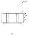
- FIG. 2illustrates a perspective view of a load pin element associated with a sleeve, which can be implemented in accordance with a preferred embodiment
- FIG. 3illustrates a cross sectional view of the load pin brake cell apparatus, which can be implemented in accordance with a preferred embodiment
- FIG. 4illustrates a front view of the load pin brake cell apparatus, which can be implemented in accordance with a preferred embodiment
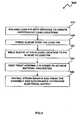
- FIG. 5illustrates a detailed flow chart of operations illustrating logical operational steps of a method for fabricating the load pin brake cell apparatus, which can be implemented in accordance with a preferred embodiment.
- FIG. 1a perspective view of a load pin element 100 is illustrated, which can be implemented in accordance with a preferred embodiment.
- the load pin element 100 depicted in FIG. 1can be formed from an elongated section of rod selected for its mechanical properties.
- the load pin element 100is composed of steel, but can be composed of other materials, depending upon design considerations.
- the load pin element 100generally possesses a cylindrical outer surface with an upper body 110 and a lower body 115.
- the load pin element 100can be machined with a pair of external grooves 120 and 125 in order to create three independent load locations 130, 132 and 134.
- the force or load to be measuredcan be applied along the independent load locations 130, 132 and 134 and can be applied downwardly through load pin element 100.
- the pair of grooves 120 and 125can be a round bottom groove formed in the roots of load pin element 100, such as depicted in FIG. 1 .
- the grooves 120 and 125can be machined in a root of the load pin element 100 in order to minimize stress concentration at the grooves 120 and 125, which in turn reduces peak stress at the grooves 120 and 125.
- the locations and shapes of the grooves 120 and 125 depicted in FIG. 1are shown for illustrative purposes only. It can be appreciated by those skilled in the art that the grooves 120 and 125 may take any shape and can be disposed in any location as may be appropriate for a particular application without departing from the spirit and scope of the disclosed embodiments.
- a sleeve 140can be installed over the load pin element 100 in order to relocate the pair of grooves 120 and 125 to the interior of the load pin element 100.
- the sleeve 140protects the grooves 120 and 125 from corrosion and hydrogen damage.
- the sleeve 140can be welded to a required depth by, for example, electron beam welding or keyhole welding at each load locations 130, 132 and 134 in order to fix the sleeve 140 to the load pin element 100.
- Weldingrefers to a permanent connection, which is preferably formed by fusion of the materials or by the formation of an alloy at the area of the parts to be connected.
- the ratio of cross sectional area between the sleeve 140 and the load pin element 100can be maintained at a minimum value in order to minimize non-linearity due to bending stresses.
- the sleeve 140can be just thick enough to prevent yielding at the grooves 120 and 125.
- the load pin element 100can be machined to form a smooth central internal bore 150.
- the central internal bore 150can be of rectangular cross-section. It is not, however, essential that the cross-section be rectangular. It may be of any other suitable shape or configuration.
- the central bore 150can be machined adjacent to the external grooves 120 and 125.
- the central bore 150can include one or more strain gages such as gages 160 and 165 as shown in FIG. 3 and can be mounted in a full-bridge configuration. The positioning and orientation of the strain gages 160 and 165 can be optimized by means of a finite element method (FEM).
- FEMfinite element method
- the central internal bore 150includes a cooperating connector 190 which can be utilized for coupling the strain gages 160 and 165 to electrical circuitry for indicating shear force.
- the load pin brake cell apparatus 200is inherently waterproof.
- the sleeve 140 and the load pin element 100 togethercan form a single homogeneous component in order to ensure predictable and total transfer of stress and strain to the strain gages 160 and 165 inside the load pin apparatus 200.
- the strain gages such as gages 160 and 165can be symmetrically arranged about the minimum depth point at a central vertical plane of the load pin element 100.
- the strain gages 160 and 165can also be bonded to the surface of the smooth central internal bore 150 in a conventional manner, as will be understood by those skilled in the art.
- the curved shape of central internal bore 150facilitates placement of the strain gages 160 and 165 at the point of maximum stress and also provides maximum stiffness for a given level of sensitivity.
- a loadcan be applied to the independent load locations 130, 132 and 134 of the load pin element 100 which bend in an amount proportional to the load, within a limited range of loading.
- the bending effect on the strain gages 160 and 165results in an output signal proportional to the applied force.
- the strain gages 160 and 165are of the common type, which undergoes a change in resistance proportional to its elongation or compression.
- a Wheatstone bridge or other accurate resistance-measuring devicecan be connected to the strain gages 160 and 165 to measure the change in resistance, all in a well known manner, to measure deflection and therefore to indicate the amount of load on the load locations 130, 132 and 134.
- the powering of the strain gages 160 and 165 as well as the amplification of the output signal voltage,can be performed by an amplifier (not shown).
- the placement of central internal bore 150 midway between upper body 110 and the lower body 115results in the isolation of the central internal bore 150 from certain of the extraneous forces and moments. Other residual or extraneous forces can be cancelled out by the Wheatstone bridge arrangement of the strain gages 160 and 165.
- the internal grooves 120 and 125 and the strain gages 160 and 165can be protected by the sleeve 140 against physical damage, moisture and contaminants.
- the load pin brake cell apparatus 200can be machined to achieve desired dimensions such that the non-linearity due to bending stresses can be minimized.
- the pair of external grooves 120 and 125can be formed in a manner to concentrate the shear forces experienced by the load pin element 100 at predetermined internal load sensing positions where strain gages 160 and 165 are located.
- the load pin brake cell apparatus 200involves metallic members and metallic supports. However, the member may alternatively be made of partly elastic ceramic materials or plastics in accordance with a relevant application.
- the sleeve 140is then preferably configured of the same or a similar material as the load pin element 100.
- a load pin element 100can be machined with a pair of grooves 120 and 125 to create three independent locations 130, 132 and 134.
- a sleeve 140can be pressed over the load pin element 100.
- the sleeve 140can be welded at each loading location 130, 132 and 134 in order to fix the sleeve 140 to the load pin element 100, as shown at block 530.
- the load pin element 100 and the sleeve 140can be heat treated in order to achieve material properties, as described at block 540.
- the strain gages 160 and 165can be installed and the assembly and electronics can be finished in order to provide an electrical output, as depicted at block 550.
Landscapes
- Physics & Mathematics (AREA)
- General Physics & Mathematics (AREA)
- Measurement Of Force In General (AREA)
- Force Measurement Appropriate To Specific Purposes (AREA)
Description
- Embodiments are generally related to force sensing devices. Embodiments are also related to load measuring pins and components thereof.
- Load measuring pins can be utilized to measure load and force and provide overload protection. The pins can be mounted into machines in place of normal shafts and can be fitted with strain gauges, allowing them to produce a signal proportional to the measured load. Load measuring pins is typically an electronic device or transducer that can be utilized to convert a force into an electrical signal. Load measuring pins are designed for many diverse applications as direct replacements for clevis or pivot pins. Such components can be typically employed in the context of rope, chain and brake anchors, sheaves, shackles, bearing blocks, pivots and other similar devices.
- Load measuring pins operate based on a shearing principle. That is, the deformation of the load-measuring pin proportional to a load can be measured through a strain gage bridge integrated in the load pin. The load pin includes a relatively massive constraint, which functions as rigid members for directing the force to be measured to the strain gage bridge while remaining substantially unaffected by extraneous forces. The constraints should be independent of typical extraneous forces that are not desired as measured quantities.
- When force is applied to the load-measuring pin along its sensitive axis, the effect on the strain gage bridge results in an output signal proportional to the applied force. The powering of the strain gage bridge, as well as the amplification of its output signal voltage, can be performed either by an external amplifier or through an internal amplifier. The amplifier allows monitoring of several levels depending on the execution.
- The majority of prior art load measuring pins can be designed with external grooves that can be machined into the outer circumference of the load pin. Such external grooves are required to provide separation between the loading surfaces and the constraint surfaces and to minimize bending stresses, which cause inherent non-linearity. These external grooves are susceptible to corrosion and hydrogen damage from plating operations, which are required to generate the bearing surface necessary in an aircraft breaking system. Similarly, the load pins does not provide an independently loaded constraint locations and a smooth internal bore for associating the strain gages. These factors affect the performance of the load-measuring pin.
- Based on the foregoing it is believed that a need exists for an improved load-measuring pin as disclosed in further detail herein.
- Examples of conventional approaches to force sensing and load measuring devices can be found in
US-A-4,858,475 ,US-A-3,857,452 ,WO-A-2004/031712 ,US-A-4,168,160 andDE-A-34 12 754 . - The following summary is provided to facilitate an understanding of some of the innovative features unique to the embodiments disclosed and is not intended to be a full description. A full appreciation of the various aspects of the embodiments can be gained by taking the entire specification, claims, drawings, and abstract as a whole.
- The present invention provides a load pin apparatus as defined in claim 1.
- The load pin element can be machined to form a smooth internal bore which includes the strain gage location associated with one or more strain gages that can be protected against physical damage, moisture and contaminants. The strain gage undergoes a change in resistance proportional to deflection of the load locations and therefore proportional to the load applied to the independent load locations. A Wheatstone bridge or other resistance-measuring device can be connected to the strain gage in order to accurately indicate the load on the load pin element. A cooperating connector can be utilized for coupling the strain gages to electrical circuitry for indicating shear force.
- The accompanying figures, in which like reference numerals refer to identical or functionally-similar elements throughout the separate views and which are incorporated in and form a part of the specification, further illustrate the embodiments and, together with the detailed description, serve to explain the embodiments disclosed herein.
FIG. 1 illustrates a perspective view of a load pin element, which can be implemented in accordance with a preferred embodiment;FIG. 2 illustrates a perspective view of a load pin element associated with a sleeve, which can be implemented in accordance with a preferred embodiment;FIG. 3 illustrates a cross sectional view of the load pin brake cell apparatus, which can be implemented in accordance with a preferred embodiment;FIG. 4 illustrates a front view of the load pin brake cell apparatus, which can be implemented in accordance with a preferred embodiment; andFIG. 5 illustrates a detailed flow chart of operations illustrating logical operational steps of a method for fabricating the load pin brake cell apparatus, which can be implemented in accordance with a preferred embodiment.- The particular values and configurations discussed in these non-limiting examples can be varied and are cited merely to illustrate at least one embodiment and are not intended to limit the scope thereof.
- Referring to
FIG. 1 , a perspective view of aload pin element 100 is illustrated, which can be implemented in accordance with a preferred embodiment. Theload pin element 100 depicted inFIG. 1 can be formed from an elongated section of rod selected for its mechanical properties. Preferably, theload pin element 100 is composed of steel, but can be composed of other materials, depending upon design considerations. Theload pin element 100 generally possesses a cylindrical outer surface with anupper body 110 and alower body 115. Theload pin element 100 can be machined with a pair ofexternal grooves independent load locations independent load locations load pin element 100. The pair ofgrooves load pin element 100, such as depicted inFIG. 1 . - The
grooves load pin element 100 in order to minimize stress concentration at thegrooves grooves grooves FIG. 1 are shown for illustrative purposes only. It can be appreciated by those skilled in the art that thegrooves - Referring to
FIG. 2 , a perspective view of a load pinbrake cell apparatus 200 associated with a sleeve is illustrated, in accordance with a preferred embodiment. Asleeve 140 can be installed over theload pin element 100 in order to relocate the pair ofgrooves load pin element 100. Thesleeve 140 protects thegrooves sleeve 140 can be welded to a required depth by, for example, electron beam welding or keyhole welding at eachload locations sleeve 140 to theload pin element 100. Welding refers to a permanent connection, which is preferably formed by fusion of the materials or by the formation of an alloy at the area of the parts to be connected. The ratio of cross sectional area between thesleeve 140 and theload pin element 100 can be maintained at a minimum value in order to minimize non-linearity due to bending stresses. Thesleeve 140 can be just thick enough to prevent yielding at thegrooves - Referring to
FIG. 3 , a cross sectional view of the load pinbrake cell apparatus 200 is illustrated, which can be implemented in accordance with a preferred embodiment. Theload pin element 100 can be machined to form a smooth centralinternal bore 150. The centralinternal bore 150 can be of rectangular cross-section. It is not, however, essential that the cross-section be rectangular. It may be of any other suitable shape or configuration. Thecentral bore 150 can be machined adjacent to theexternal grooves central bore 150 can include one or more strain gages such asgages FIG. 3 and can be mounted in a full-bridge configuration. The positioning and orientation of the strain gages 160 and 165 can be optimized by means of a finite element method (FEM). - The central
internal bore 150 includes a cooperatingconnector 190 which can be utilized for coupling thestrain gages strain gages connector 190 of theload pin element 100 is totally contained within the small centralinternal bore 150, the load pinbrake cell apparatus 200 is inherently waterproof. Thesleeve 140 and theload pin element 100 together can form a single homogeneous component in order to ensure predictable and total transfer of stress and strain to thestrain gages load pin apparatus 200. - The strain gages such as
gages load pin element 100. The strain gages 160 and 165 can also be bonded to the surface of the smooth centralinternal bore 150 in a conventional manner, as will be understood by those skilled in the art. The curved shape of centralinternal bore 150 facilitates placement of thestrain gages independent load locations load pin element 100 which bend in an amount proportional to the load, within a limited range of loading. The bending effect on thestrain gages - A Wheatstone bridge or other accurate resistance-measuring device can be connected to the
strain gages load locations strain gages internal bore 150 midway betweenupper body 110 and thelower body 115 results in the isolation of the centralinternal bore 150 from certain of the extraneous forces and moments. Other residual or extraneous forces can be cancelled out by the Wheatstone bridge arrangement of thestrain gages internal grooves strain gages sleeve 140 against physical damage, moisture and contaminants. - Referring to
FIG. 4 , a front view of the load pinbrake cell apparatus 200 is illustrated, in accordance with a preferred embodiment. The load pinbrake cell apparatus 200 can be machined to achieve desired dimensions such that the non-linearity due to bending stresses can be minimized. The pair ofexternal grooves load pin element 100 at predetermined internal load sensing positions wherestrain gages brake cell apparatus 200 involves metallic members and metallic supports. However, the member may alternatively be made of partly elastic ceramic materials or plastics in accordance with a relevant application. Thesleeve 140 is then preferably configured of the same or a similar material as theload pin element 100. - Referring to
FIG. 5 , a detailed flow chart of operations illustrating logical operational steps of a method 600 for fabricating the load pin brake cell apparatus is illustrated, in accordance with a preferred embodiment. As indicated atblock 510, aload pin element 100 can be machined with a pair ofgrooves independent locations block 520, asleeve 140 can be pressed over theload pin element 100. Thesleeve 140 can be welded at eachloading location sleeve 140 to theload pin element 100, as shown atblock 530. Theload pin element 100 and thesleeve 140 can be heat treated in order to achieve material properties, as described atblock 540. The strain gages 160 and 165 can be installed and the assembly and electronics can be finished in order to provide an electrical output, as depicted atblock 550. - It will be appreciated that variations of the above-disclosed and other features and functions, or alternatives thereof, may be desirably combined into many other different systems or applications. Also that various presently unforeseen or unanticipated alternatives, modifications, variations or improvements therein may be subsequently made by those skilled in the art which are also intended to be encompassed by the following claims.
Claims (9)
- A load pin apparatus (200) having a load pin element (100) with a pair of external grooves (120, 125) therein in order to form a plurality of independent load locations (130, 132, 134), wherein said pair of external grooves (120, 125) define shear planes which are located between forces being measured by said load pin apparatus (200), and having at least two strain gages (160, 165) affixed to said load pin element (100) in a central internal bore (150) to sense a deformation, the load pin apparatus (200)characterised by:a sleeve (140) associated with said load pin element (100), wherein said sleeve (140) is welded to said load pin element (100) in each of the plurality of independent load locations (130, 132, 134) in order to relocate said pair of grooves (120, 125) to an interior of said load pin element (100); andwherein said sleeve (140) and said load pin element (100) form a homogeneous component that provides a predictable transfer of strain to said at least two strain gages (160, 165) within said load pin element (100).
- The load pin apparatus (200) of claim 1 further comprising:a cooperating connector (190) for coupling said at least two strain gages (160, 165) to an electrical circuit.
- The load pin apparatus (200) of claim 1, wherein said sleeve (140) possesses a thickness sufficient to prevent a yielding at said pair of grooves (120, 125).
- The load pin apparatus (200) of claim 1, wherein said at least two strain gauges (160, 165) are responsive to a strain on said load pin element (100) in accordance with a force on said plurality of independent load locations (130, 132, 134).
- The load pin apparatus (200) of claim 1, wherein said pair of external grooves (120, 125) reduces a non-linearity due to bending stresses by minimizing a ratio of a cross-sectional area between said sleeve (140) and said load pin element (100), and wherein said sleeve (140) possesses a thickness sufficient to prevent a yielding at said pair of grooves (120, 125).
- The load pin apparatus (200) of claim 1 further comprising:a cooperating connector (190) for coupling said at least two strain gages (160, 165) to an electrical circuit for indicating shear force thereof, and wherein said sleeve (140) possesses a thickness sufficient to prevent a yielding at said pair of grooves (120, 125).
- The load pin apparatus (200) of claim 1 wherein:said at least two strain gauges (160, 165) are responsive to a strain on said load pin element (100) in accordance with a force on said plurality of independent load locations (130, 132, 134); andsaid sleeve (140) possesses a thickness sufficient to prevent a yielding at said pair of grooves (120, 125).
- The load pin apparatus (200) of claim 1, wherein the plurality of independent load locations (130, 132, 134) include a first load location (130), a second load location (132) and a third load location (134), and wherein the sleeve (140) is welded to said load pin element (100) at each of said first load location (130), the second load location (132) and the third load location (134).
- The load pin apparatus (200) of claim 1, wherein each of the at least two strain gages (160, 165) are located along a smooth internal bore of the central internal bore (150).
Applications Claiming Priority (1)
| Application Number | Priority Date | Filing Date | Title |
|---|---|---|---|
| US12/016,402US7644636B2 (en) | 2008-01-18 | 2008-01-18 | Load pin brake cell apparatus |
Publications (3)
| Publication Number | Publication Date |
|---|---|
| EP2081007A2 EP2081007A2 (en) | 2009-07-22 |
| EP2081007A3 EP2081007A3 (en) | 2011-01-26 |
| EP2081007B1true EP2081007B1 (en) | 2012-04-04 |
Family
ID=40561056
Family Applications (1)
| Application Number | Title | Priority Date | Filing Date |
|---|---|---|---|
| EP09150653AExpired - Fee RelatedEP2081007B1 (en) | 2008-01-18 | 2009-01-15 | Load measuring pin |
Country Status (2)
| Country | Link |
|---|---|
| US (1) | US7644636B2 (en) |
| EP (1) | EP2081007B1 (en) |
Families Citing this family (10)
| Publication number | Priority date | Publication date | Assignee | Title |
|---|---|---|---|---|
| FR2959723A1 (en)* | 2010-05-06 | 2011-11-11 | Skf Aerospace France | FLYING DEVICE CONTROL SYSTEM, FLIGHT CONTROL DEVICE INCLUDING SUCH A SYSTEM, AND USE OF SUCH A SYSTEM |
| US8659307B2 (en)* | 2010-08-17 | 2014-02-25 | Rosemount Aerospace Inc. | Capacitive sensors for monitoring load bearing on pins |
| US10131419B2 (en) | 2010-10-15 | 2018-11-20 | Goodrich Corporation | Systems and methods for detecting landing gear ground loads |
| US8474326B2 (en)* | 2011-03-15 | 2013-07-02 | Honeywell International Inc. | Load pin with increased performance |
| US9261419B2 (en)* | 2014-01-23 | 2016-02-16 | Honeywell International Inc. | Modular load structure assembly having internal strain gaged sensing |
| CH711008A1 (en)* | 2015-04-30 | 2016-10-31 | Kistler Holding Ag | Contact force testing apparatus, use of such a contact force testing apparatus, and a method of manufacturing such a contact force testing apparatus. |
| US20160369877A1 (en)* | 2015-06-17 | 2016-12-22 | Moog Inc. | No-back brake functionality monitor |
| IL247408B (en)* | 2016-08-21 | 2018-03-29 | Elbit Systems Ltd | System and method for detecting weakening of the adhesion strength between structural elements |
| US10323992B2 (en)* | 2016-09-26 | 2019-06-18 | Tecsis Gmbh | Force measuring load pin having at least one sensor and a slot that divides the load pin into upper and lower portions |
| US11840330B2 (en) | 2021-02-24 | 2023-12-12 | Textron Innovations Inc. | Downstop load sensing system |
Family Cites Families (14)
| Publication number | Priority date | Publication date | Assignee | Title |
|---|---|---|---|---|
| US3857452A (en)* | 1974-02-14 | 1974-12-31 | Tri Coastal Ind Inc | Dump truck load-sensing assembly |
| DE2648192C2 (en) | 1976-10-25 | 1985-08-01 | Wolfhard Dipl.-Ing. 6108 Weiterstadt Sack | Device for measuring and / or monitoring the axial force on a tool spindle |
| DE3412754A1 (en) | 1984-04-05 | 1985-10-17 | Philips Patentverwaltung Gmbh, 2000 Hamburg | Force sensor |
| US4858475A (en)* | 1987-05-26 | 1989-08-22 | Revere Corporation Of America | Apparatus and method for measuring strain |
| US5309372A (en)* | 1989-07-17 | 1994-05-03 | Kawasaki Steel Corp. | System and method for determining routes between circuit blocks of a programmable logic device by determining a load pin which is closest to the center of gravity of a plurality of load pins |
| US6309208B1 (en)* | 1997-06-13 | 2001-10-30 | Synventive Molding Solutions, Inc. | Apparatus for proportionally controlling fluid delivery to a mold |
| US6408688B2 (en)* | 1999-07-16 | 2002-06-25 | Strainsert Company | Heavy truck brake system using instrumented anchor pins |
| CA2299669A1 (en)* | 2000-03-06 | 2001-09-06 | Corporation De Frein Newtech Inc. | Sensitive control of brakes from the steering wheel |
| US6370971B1 (en)* | 2000-10-23 | 2002-04-16 | Tedea-Huntleigh, Inc. | Pulley hub load cell |
| US6766685B2 (en)* | 2001-08-31 | 2004-07-27 | Timothy B. Foley | Method of sensing and correcting brake functions in moving heavy truck brake systems using instrumented anchor pins |
| DE10202400A1 (en)* | 2002-01-21 | 2003-08-14 | Sartorius Gmbh | Load cell |
| US6769315B2 (en)* | 2002-03-13 | 2004-08-03 | David L. Stevenson | Shackle pin with internal signal conditioner |
| US20040055832A1 (en)* | 2002-09-19 | 2004-03-25 | Edscha North America | Electronic parking brake with feedback control and cable strain gage |
| DE10245768B8 (en) | 2002-09-25 | 2005-02-10 | EBM Brosa Messgeräte GmbH & Co. KG | Force transducer for measuring axle forces |
- 2008
- 2008-01-18USUS12/016,402patent/US7644636B2/ennot_activeExpired - Fee Related
- 2009
- 2009-01-15EPEP09150653Apatent/EP2081007B1/ennot_activeExpired - Fee Related
Also Published As
| Publication number | Publication date |
|---|---|
| US7644636B2 (en) | 2010-01-12 |
| US20090183561A1 (en) | 2009-07-23 |
| EP2081007A2 (en) | 2009-07-22 |
| EP2081007A3 (en) | 2011-01-26 |
Similar Documents
| Publication | Publication Date | Title |
|---|---|---|
| EP2081007B1 (en) | Load measuring pin | |
| US8359932B2 (en) | Systems and methods for mounting landing gear strain sensors | |
| EP2789997B1 (en) | Load detecting device | |
| US6555767B1 (en) | Composite load cell | |
| EP1380823A2 (en) | Drilling mechanics load cell sensor | |
| CN101532817B (en) | Resistance strain gauge and sensor using resistance strain gauge to change stress transfer mode | |
| US9395256B2 (en) | Low profile multi-axis load cell | |
| KR102359030B1 (en) | Mechanical component having a force sensor | |
| US8933713B2 (en) | Capacitive sensors for monitoring loads | |
| US20130126249A1 (en) | Load cell and applications thereof | |
| CA2755101C (en) | Capacitive sensors for monitoring loads | |
| KR101179169B1 (en) | Temperature compensated load cell comprising strain gauges | |
| US6898989B2 (en) | Load cell | |
| EP3025129B1 (en) | Flex circuit interface for strain gauges | |
| US5569866A (en) | Force measuring device | |
| JPS62273423A (en) | Measured value detector | |
| WO2003081170A8 (en) | Strain-measuring device | |
| US4148219A (en) | Strain gage load cell | |
| EP2891870B1 (en) | Detection device for detecting load and moment, and artificial limb including detection device | |
| KR20060055682A (en) | Strain gauge sensor | |
| CN207231688U (en) | A kind of A seating sensor for measuring boom support member stress | |
| GB2343751A (en) | Bi-axial stress sensor assembly | |
| US20050241408A1 (en) | Load Cell Insensitive to Angular Misalignments and Shock Loads | |
| US20030213122A1 (en) | Polymer/metal composite load cell |
Legal Events
| Date | Code | Title | Description |
|---|---|---|---|
| PUAI | Public reference made under article 153(3) epc to a published international application that has entered the european phase | Free format text:ORIGINAL CODE: 0009012 | |
| 17P | Request for examination filed | Effective date:20090115 | |
| AK | Designated contracting states | Kind code of ref document:A2 Designated state(s):AT BE BG CH CY CZ DE DK EE ES FI FR GB GR HR HU IE IS IT LI LT LU LV MC MK MT NL NO PL PT RO SE SI SK TR | |
| AX | Request for extension of the european patent | Extension state:AL BA RS | |
| PUAL | Search report despatched | Free format text:ORIGINAL CODE: 0009013 | |
| AK | Designated contracting states | Kind code of ref document:A3 Designated state(s):AT BE BG CH CY CZ DE DK EE ES FI FR GB GR HR HU IE IS IT LI LT LU LV MC MK MT NL NO PL PT RO SE SI SK TR | |
| AX | Request for extension of the european patent | Extension state:AL BA RS | |
| RIC1 | Information provided on ipc code assigned before grant | Ipc:G01L 1/22 20060101AFI20110629BHEP | |
| AKX | Designation fees paid | Designated state(s):FR | |
| REG | Reference to a national code | Ref country code:DE Ref legal event code:R108 Effective date:20110928 | |
| GRAP | Despatch of communication of intention to grant a patent | Free format text:ORIGINAL CODE: EPIDOSNIGR1 | |
| GRAS | Grant fee paid | Free format text:ORIGINAL CODE: EPIDOSNIGR3 | |
| GRAA | (expected) grant | Free format text:ORIGINAL CODE: 0009210 | |
| AK | Designated contracting states | Kind code of ref document:B1 Designated state(s):FR | |
| PLBE | No opposition filed within time limit | Free format text:ORIGINAL CODE: 0009261 | |
| STAA | Information on the status of an ep patent application or granted ep patent | Free format text:STATUS: NO OPPOSITION FILED WITHIN TIME LIMIT | |
| 26N | No opposition filed | Effective date:20130107 | |
| PGFP | Annual fee paid to national office [announced via postgrant information from national office to epo] | Ref country code:FR Payment date:20130128 Year of fee payment:5 | |
| REG | Reference to a national code | Ref country code:FR Ref legal event code:ST Effective date:20140930 | |
| PG25 | Lapsed in a contracting state [announced via postgrant information from national office to epo] | Ref country code:FR Free format text:LAPSE BECAUSE OF NON-PAYMENT OF DUE FEES Effective date:20140131 |