EP2080715B2 - Beaker made out of a paper material - Google Patents
Beaker made out of a paper materialDownload PDFInfo
- Publication number
- EP2080715B2 EP2080715B2EP09000695.8AEP09000695AEP2080715B2EP 2080715 B2EP2080715 B2EP 2080715B2EP 09000695 AEP09000695 AEP 09000695AEP 2080715 B2EP2080715 B2EP 2080715B2
- Authority
- EP
- European Patent Office
- Prior art keywords
- cup
- sleeve
- jacket
- interior
- chime
- Prior art date
- Legal status (The legal status is an assumption and is not a legal conclusion. Google has not performed a legal analysis and makes no representation as to the accuracy of the status listed.)
- Active
Links
Images


Classifications
- B—PERFORMING OPERATIONS; TRANSPORTING
- B65—CONVEYING; PACKING; STORING; HANDLING THIN OR FILAMENTARY MATERIAL
- B65D—CONTAINERS FOR STORAGE OR TRANSPORT OF ARTICLES OR MATERIALS, e.g. BAGS, BARRELS, BOTTLES, BOXES, CANS, CARTONS, CRATES, DRUMS, JARS, TANKS, HOPPERS, FORWARDING CONTAINERS; ACCESSORIES, CLOSURES, OR FITTINGS THEREFOR; PACKAGING ELEMENTS; PACKAGES
- B65D21/00—Nestable, stackable or joinable containers; Containers of variable capacity
- B65D21/02—Containers specially shaped, or provided with fittings or attachments, to facilitate nesting, stacking, or joining together
- B65D21/0233—Nestable containers
- B—PERFORMING OPERATIONS; TRANSPORTING
- B65—CONVEYING; PACKING; STORING; HANDLING THIN OR FILAMENTARY MATERIAL
- B65D—CONTAINERS FOR STORAGE OR TRANSPORT OF ARTICLES OR MATERIALS, e.g. BAGS, BARRELS, BOTTLES, BOXES, CANS, CARTONS, CRATES, DRUMS, JARS, TANKS, HOPPERS, FORWARDING CONTAINERS; ACCESSORIES, CLOSURES, OR FITTINGS THEREFOR; PACKAGING ELEMENTS; PACKAGES
- B65D3/00—Rigid or semi-rigid containers having bodies or peripheral walls of curved or partially-curved cross-section made by winding or bending paper without folding along defined lines
- B65D3/10—Rigid or semi-rigid containers having bodies or peripheral walls of curved or partially-curved cross-section made by winding or bending paper without folding along defined lines characterised by form of integral or permanently secured end closure
- B65D3/12—Flanged discs permanently secured, e.g. by adhesives or by heat-sealing
- B65D3/14—Discs fitting within container end and secured by bending, rolling, or folding operations
- B—PERFORMING OPERATIONS; TRANSPORTING
- B31—MAKING ARTICLES OF PAPER, CARDBOARD OR MATERIAL WORKED IN A MANNER ANALOGOUS TO PAPER; WORKING PAPER, CARDBOARD OR MATERIAL WORKED IN A MANNER ANALOGOUS TO PAPER
- B31B—MAKING CONTAINERS OF PAPER, CARDBOARD OR MATERIAL WORKED IN A MANNER ANALOGOUS TO PAPER
- B31B50/00—Making rigid or semi-rigid containers, e.g. boxes or cartons
- B31B50/60—Uniting opposed surfaces or edges; Taping
- B—PERFORMING OPERATIONS; TRANSPORTING
- B65—CONVEYING; PACKING; STORING; HANDLING THIN OR FILAMENTARY MATERIAL
- B65D—CONTAINERS FOR STORAGE OR TRANSPORT OF ARTICLES OR MATERIALS, e.g. BAGS, BARRELS, BOTTLES, BOXES, CANS, CARTONS, CRATES, DRUMS, JARS, TANKS, HOPPERS, FORWARDING CONTAINERS; ACCESSORIES, CLOSURES, OR FITTINGS THEREFOR; PACKAGING ELEMENTS; PACKAGES
- B65D81/00—Containers, packaging elements, or packages, for contents presenting particular transport or storage problems, or adapted to be used for non-packaging purposes after removal of contents
- B65D81/38—Containers, packaging elements, or packages, for contents presenting particular transport or storage problems, or adapted to be used for non-packaging purposes after removal of contents with thermal insulation
- B65D81/3865—Containers, packaging elements, or packages, for contents presenting particular transport or storage problems, or adapted to be used for non-packaging purposes after removal of contents with thermal insulation drinking cups or like containers
- B65D81/3869—Containers, packaging elements, or packages, for contents presenting particular transport or storage problems, or adapted to be used for non-packaging purposes after removal of contents with thermal insulation drinking cups or like containers formed with double walls, i.e. hollow
- B—PERFORMING OPERATIONS; TRANSPORTING
- B31—MAKING ARTICLES OF PAPER, CARDBOARD OR MATERIAL WORKED IN A MANNER ANALOGOUS TO PAPER; WORKING PAPER, CARDBOARD OR MATERIAL WORKED IN A MANNER ANALOGOUS TO PAPER
- B31B—MAKING CONTAINERS OF PAPER, CARDBOARD OR MATERIAL WORKED IN A MANNER ANALOGOUS TO PAPER
- B31B2105/00—Rigid or semi-rigid containers made by assembling separate sheets, blanks or webs
- B31B2105/002—Making boxes characterised by the shape of the blanks from which they are formed
- B31B2105/0022—Making boxes from tubular webs or blanks, e.g. with separate bottoms, including tube or bottom forming operations
- B—PERFORMING OPERATIONS; TRANSPORTING
- B31—MAKING ARTICLES OF PAPER, CARDBOARD OR MATERIAL WORKED IN A MANNER ANALOGOUS TO PAPER; WORKING PAPER, CARDBOARD OR MATERIAL WORKED IN A MANNER ANALOGOUS TO PAPER
- B31B—MAKING CONTAINERS OF PAPER, CARDBOARD OR MATERIAL WORKED IN A MANNER ANALOGOUS TO PAPER
- B31B2110/00—Shape of rigid or semi-rigid containers
- B31B2110/10—Shape of rigid or semi-rigid containers having a cross section of varying size or shape, e.g. conical or pyramidal
- B—PERFORMING OPERATIONS; TRANSPORTING
- B31—MAKING ARTICLES OF PAPER, CARDBOARD OR MATERIAL WORKED IN A MANNER ANALOGOUS TO PAPER; WORKING PAPER, CARDBOARD OR MATERIAL WORKED IN A MANNER ANALOGOUS TO PAPER
- B31B—MAKING CONTAINERS OF PAPER, CARDBOARD OR MATERIAL WORKED IN A MANNER ANALOGOUS TO PAPER
- B31B50/00—Making rigid or semi-rigid containers, e.g. boxes or cartons
- B31B50/59—Shaping sheet material under pressure
- B31B50/594—Modifying the shape of tubular boxes or of paper bottle necks
Definitions
- the inventionrelates to a cup made of a paper material with a fillable interior, which is formed by a conical jacket and a base, the base at the lower end of the interior being fastened to the jacket with a frame in a substantially liquid-tight manner, the jacket and / or the
- the bottom in the area of the frame and / or the frame itselfhas an outwardly protruding widening at least in one area of the circumference and wherein a lower edge of the widening forms a standing surface for the cup and the cup has an outer jacket.
- the inventionfurther relates to a method for producing a cup from a paper material, which consists of a conical shell and a base fastened by a frame in the region of the lesser circumference of the shell, the base being connected to the shell to form a frame and during the formation of the frame, the casing and / or the base in the area of the frame and / or the frame itself is widened outwards at least in one area along the circumference, so that a lower edge of the widening forms a standing surface for the cup.
- a paper materialwhich consists of a conical shell and a base fastened by a frame in the region of the lesser circumference of the shell, the base being connected to the shell to form a frame and during the formation of the frame, the casing and / or the base in the area of the frame and / or the frame itself is widened outwards at least in one area along the circumference, so that a lower edge of the widening forms a standing surface for the cup.
- a mug of this typeis by that JP2001-192015A State of the art.
- the frame of the well-known cupwidens towards the bottom.
- the wideningis used to attach an outer jacket which surrounds the jacket delimiting the interior space, forming a cavity. Since the widening of the frame defines the distance between the inner jacket and the outer jacket, the widening of the frame must be circumferential.
- the outer jacketis placed around the frame, folded inwards and fastened there. When attaching the outer jacket to the frame, it can happen that the tightness of the frame is impaired. In addition, the attachment of the outer jacket is very complex due to the hammering.
- the outer jacketcompletely encloses the frame so that it is no longer visible from the outside.
- the outer jacketcan only be pressed on from the inside with a very small amount of force, which the frame itself can absorb. If the pressure is too high, the frame can tear; on the other hand, the attachment of the outer jacket can be inadequate if the pressure is too low.
- the outer jacketis connected by heat sealing, it can happen that the seal between the bottom and the jacket delimiting the interior is loosened again, since no counter-pressure can be exerted on the frame from the outside when the inwardly folded outer jacket is sealed.
- the frameis a very important element of the cup.
- the frameis necessary for the connection between the jacket and the floor.
- At least two material layerslie on top of one another in the thickness direction on the frame, namely the material of the base and the material of the jacket delimiting the interior space.
- the baseis preferably designed in the shape of a pot, the open side of which faces away from the filling opening of the cup.
- the at least two material layersare therefore preferably arranged along the wall of the pot-shaped base.
- the jacketis wrapped around the material of the floor, and that the frame consists of three or more layers of material.
- the material of the bottomis glued or sealed to the material of the jacket in the area of the frame in order to be liquid-tight for at least a certain period of time.
- paper materialfrom which the base and the jacket are made can be understood to mean different materials which have at least one layer of paper, cardboard or cardboard.
- the materialcan have one or more layers of plastic and / or aluminum.
- the paper materialis waxed or lacquered in order to be resistant to the liquid to be filled into the interior.
- the paper materialis preferably coated with a thin plastic layer, preferably made of polyethylene, at least on the side delimiting the interior space. In contrast to pure plastic material, the formability and in particular the ductility of such paper material is limited. If the deformation is too great, the paper material itself or a coating provided can tear, so that the tightness is impaired. In the case of cups made of paper material, the frame is therefore an essential design feature that cannot be dispensed with.
- a cup made of a paper material with a conical shell and a bottomis known, the bottom at the lower end of the interior space being fastened to the shell with a frame, the frame having an outwardly projecting widening in its lowermost section, a lower edge of the Expansion forms a standing surface for the cup.
- the cup shown therealso has an outer jacket which is arranged between the widened section of the frame and an upper rim of the cup.
- a drinking cup with a conical jacket and a baseis known, in which the jacket and the base are connected to one another by means of a frame, the frame having a truncated cone shape that widens from the base in the direction of the base of the cup.
- the cup shownhas no outer jacket.
- the inventionis based on the object of simplifying the manufacturability of a cup of the type mentioned at the beginning and of avoiding sealing problems on the frame.
- the footprint of the cupis enlarged by the widening, so that the cup has improved stability.
- the wideningis not or not completely covered by an outer jacket, so that the material of the jacket or the base directly forms the standing surface. As a result, the tightness of the frame cannot be impaired by the attachment of the additional material of the outer jacket.
- the wideningis formed continuously and uniformly along the circumference. If the paper material is coated, it is advantageous to form the widening only so large that the coating does not tear.
- the frameis preferably widened over its entire height.
- the framethen has - seen in an axial section - an essentially constant angle of inclination to the central axis of the cup.
- the framecontains different height areas which have different angles of inclination.
- the area of the frame adjoining the bottomcan remain in its original shape, while the lower edge of the frame is widened to a greater extent.
- the upper height areacan mainly serve to seal off the fillable interior space and connects the conical jacket to the floor in a substantially liquid-tight manner. In this upper height range, the jacket and the wall are sealed or glued to one another.
- the material of the jacket delimiting the interior space and / or the wall of the baseis widened and, with its lower edge, forms an enlarged standing surface for the cup.
- a liquid-tight connection between the material of the base and the material of the casingis no longer absolutely necessary, so that sealing or gluing in the lower height range can at least partially be dispensed with.
- the cup according to the inventioncan be used in a very versatile manner, since it can be used both without an outer jacket and with different outer jackets.
- a heat-insulating jacketis preferably provided which partially surrounds the jacket delimiting the interior space, forming a cavity.
- the outer casingis preferably pushed onto the conical casing delimiting the interior space along the central axis and fixed after the frame has been shaped and widened.
- a stackable mugfor example, is made possible by the EP 1 227 042 B1 known.
- the jacket of the known cup delimiting the interior spacehas a first means for holding another cup of the same type.
- the known cuphas a second means for holding on an outer casing which surrounds the casing delimiting the interior space with a heat-insulating cavity.
- the second means of holdingis formed by an inwardly directed curl attached to the lower end of the outer jacket.
- the second holding means attached to the outer casingcan interact with a first holding means attached to a similar cup.
- the known cuphas the disadvantage that the forces occurring during stacking are transmitted via the jacket delimiting the interior space and via the outer jacket.
- the forces that have to be passed on within the cup from the first holding means to the second holding meansare first transmitted through the jacket delimiting the interior space to the connection point between the inner jacket and the outer jacket and passed on to the outer jacket via this connection point.
- the forcesare then passed on to the second holding means, which is designed as a curl, and there they are transferred to the next cup.
- both the inner jacket and the outer jacketmust be designed to be stable enough to be able to absorb the forces that occur.
- the connection point between the outer jacket and the inner jacketmust also be designed for the maximum forces that occur.
- a means for holding another cup of the same typeis arranged on the frame, which means can cooperate with a similar cup when the cup is stacked.
- the means for holdingis advantageously formed by the widening. Provision is preferably made for a first holding means to be arranged on the jacket delimiting the interior space, so that when the cup is stacked, it can interact with a second holding means attached to the widening of a similar cup.
- the second means for holdingis arranged on the jacket delimiting the interior space or on the floor or on a frame through which the jacket delimiting the interior space is connected to the floor.
- the second means for holdingis attached to a component of the cup which is in contact with the interior space that can be filled.
- the cup according to the inventionhas the advantage that it can be stacked securely and stably even without the presence of an outer jacket and can also be unstacked again without jamming. If it is provided that a heat-insulating outer jacket is assigned to the cup, this can be largely independent of and free from that of the cup EP 1 227 042 B1 shape existing constraints. The forces occurring during stacking are only passed on from the first means for holding to the second means for holding within the jacket delimiting the interior space. An outer jacket is therefore not absolutely necessary. If, however, an outer jacket is to be present, it will not be stressed by the forces that occur during stacking.
- the frame, through which the jacket delimiting the interior space is connected to the floor,is a very stable part of the cup and is particularly suitable for absorbing forces.
- the forces occurring during stackingare essentially transmitted through the jacket delimiting the interior space from the first holding means to the second holding means, which can be formed by the widening on the frame. In this way, very stable stacks with a large number of cups can be formed which do not become wedged into one another even if the stacks are exposed to impacts or, for example, are jerkily deposited on the ground.
- the jacket delimiting the interior space and the baseare strong enough to absorb the forces that occur during stacking, since they also have to absorb the forces that occur during filling.
- the dimensions of the second means for holdingare adapted to the dimensions of the first means for holding another cup of the same type.
- the first means for holding another cup of the same typecan be shaped as desired. It is essential that a contour is formed that can absorb forces acting in the axial direction of the cup, that is to say the forces that act between two cups when they are stacked.
- the first means for holdingis preferably designed as a bead or rib which is molded into the jacket delimiting the interior space at least in one area along the circumference.
- the bead or ribcan be designed continuously or with interruptions along the circumference.
- the cuphas a heat-insulating outer jacket
- the heat-insulating outer jacketcan be configured as desired.
- the outer jacketcan be made from a plastic, paper or composite material, for example.
- the outer jacketcan also be corrugated, corrugated, embossed or provided with a foamed layer.
- the outer jacketcan also have a multilayer design, for example a corrugated intermediate layer can be provided, which is covered by an outer layer laid smoothly over it. Because the cup according to the invention can be stacked independently of the outer casing, one and the same inner cup can be combined in a simple and almost arbitrary manner with a wide variety of outer casings. Without changing the shape and dimensions of the inner cup or the components forming the fillable interior, different cups with different optical and haptic appearances can be created, since the appearance that the user of the cup perceives is mainly determined by the design of the outer shell.
- the outer jacketcan be fixed to the inner cup, for example, by sealing or gluing. It creates a secure connection between the outer jacket and the jacket delimiting the interior space, so that the outer jacket is reliably prevented from slipping, even if the outer jacket is only low in height.
- the outer casingends below the first means for holding another cup of the same type or even below the bottom.
- the first holding means attached to the inner jacketis thereby covered by the outer jacket and is no longer visible from the outside.
- the outer jacketends above the widening of the frame.
- the expansion on the frameis preferably carried out by the interaction of a tool arranged outside and inside the frame. The widening can thereby be shaped very precisely.
- the wideningis advantageously widened outward so far that a parallel to the jacket delimiting the interior space, which is applied to the lower edge of the widening, runs at a certain distance outside the jacket delimiting the interior space. So that a provided outer jacket does not hinder the stacking of the cup, it is advantageous that the outer contour of the outer jacket is located within the parallels to the jacket delimiting the interior, which is placed on the widening of the frame.
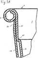
- the cup 1 shownconsists essentially of a conical jacket 2 and a cup-shaped base 3.
- the open side of the cup-shaped base 3is arranged in such a way that it faces away from the filling opening of the cup 1.
- the bottom 3is connected with its wall 31 in the area of the lesser circumference of the casing 2 in a liquid-tight manner by forming a frame 4.
- the material of the jacket 2is wrapped around the wall 31 of the base 3 and folded inward.
- the jacket 2 and the base 3form a fillable interior space 5 of the cup 1.
- the fillable interior space 5has a height A.
- the jacket 2 delimiting the interior space 5has on its upper edge, that is to say in the region of the larger circumference, an outwardly flanged lip curl 6 which surrounds the filling opening.
- the "conical” property of the jacket 2is to be understood as meaning that the jacket 2 is in the in Figure 1
- the illustrated longitudinal section from the lip curl 6 to the bottom 3tapers at least in sections.
- the jacket 2has an angle of inclination ⁇ to the central axis 13 of the cup 1 above a bead 8 in the area of the fillable interior 5. Below the bead 8, the jacket 2 then has a circular cylindrical shape up to the bottom 3. It is irrelevant what shape the jacket 2 has in cross section.
- the jacket 2is preferably circular in cross section, but can alternatively also be, for example, oval or rectangular with rounded corners.
- the cup 1In the case of a round cross section of the conical shell 2, the cup 1 has a shape similar to a truncated cone, while in the case of a rectangular cross section of the conical shell 2 it has a shape that is more like a truncated pyramid.
- the frame 4has an outwardly projecting widening 10 at least in one area along its circumference.
- wideningis to be understood as meaning that the frame 4 is exposed to the outside around the central axis 13 in relation to a circular cylinder, so that the frame 4 includes a cross-sectional area that widens downwards towards the base.
- a lower edge 14 of the widening 10 on the frame 4forms the standing surface for the cup 1.
- the cup 1is in use on its standing area, which is enlarged by the widening 10. This makes it difficult for the cup 1 to tip over.
- the widening 10is preferably designed to run around the circumference of the frame 4.
- the outwardly projecting widening 10also forms a means 9 for holding another cup 1 'of the same type, which can interact with a similar cup 1' when the cup 1 is stacked.
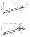
- the stacking of the cup 1 in a similar cup 1 'is shown in FIG Figure 2 shown.
- the widening 10 as a means 9 for stacking the cup 1can interact, for example, with a jacket 2 'delimiting the interior space 5'. Further means of stacking are not absolutely necessary.
- the jacket 2 delimiting the interior space 5preferably has at least one first means 7 for holding another cup 1 of the same type, which can be shaped as desired. It is important that the first means 7 for holding has at least one contour which can absorb forces acting in the direction of the central axis 13 of the cup 1, that is to say forces which act between two cups when they are stacked.
- the first means 7 for holdingcan be formed, for example, by a rib or bead 8 which protrudes into the interior of the cup 1.
- Said second means 9 in the form of the widening 10is arranged on the frame 4, on which the jacket 2 delimiting the interior space 5 is crimped around the cup-shaped deep-drawn base 3 and sealed in a liquid-tight manner.
- the dimension Y of the second means 9 for holdingis adapted to the dimension X of the first means 7 for holding the other cup 1 'of the same type.
- the dimension X of the first means 7 for holdingcorresponds to the inner diameter of the jacket 2 above the bead 8.
- the dimension Y of the second means 9 for holdingcorresponds to the largest outer diameter of the widening 10 on the frame 4, i.e. the diameter that surrounds the widening 10.
- the adaptation of the dimensions X and Yis advantageously carried out in such a way that the dimension Y is selected to be somewhat smaller or at most equal to the dimension X.
- the cooperation of the first means 7 and the second means 9 for holdingis at the in Figure 2 illustrated cups 1 and 1 'clearly.
- the first means 7 'of the cup 1'which is attached to the jacket 2 'delimiting the interior 5', receives the second means 9 of the cup 1.
- the widening 10 attached to the frame 4 of the cup 1 and especially the lower end of the widening 10, that is to say about the standing surface at the lower edge 14,is supported by the bead 8 'which is molded into the jacket 2'.
- the aforementioned adaptation of the dimension X of the first means 7 for holding to the dimension Y of the second means 9 for holdingensures that the widening 10 of the cup 1 is stable and secure on the bead 8 'of the similar cup 1' without standing up but to jam in the conical jacket 2 '.
- the forces that occur when stacking along the central axis 13, for example the weight of the cup 1 and the cups that may still be stacked above it,are safely absorbed by the bead 8 'as a means 7' for holding and via the jacket 2 'to the lower edge 14 'of the frame 4' of the lower cup 1 'and passed on from the standing surface located on the lower edge 14' to the ground. Even if very high forces occur in the direction of the central axis 13, the cup 1 or 1 'can be easily removed when unstacking.
- the frame 4has a constant angle of inclination ⁇ to the central axis 13 of the cup 1.
- the angle of inclination ⁇ of the height area B of the frame 4is in any case directed such that the frame 4 widens towards the lower edge 14 and has the largest dimension Y at its lower edge 14, i.e. the lower edge 14 seen parallel to the central axis 13 the frame 4 forms the region of the frame 4 which is most distant from the central axis 13.
- the angle of inclination ⁇is directed in such a way that the conicity runs in the opposite direction.
- the diameter Y surrounding the widening 10is preferably greater than the diameter D which surrounds the area of the base 3 that is in contact with the interior space 5. So that effective stacking is possible and the stacking height does not become unnecessarily high, it is advantageous if the means 7 for holding, which is arranged on the casing 2 delimiting the interior space 5, is not arranged higher above the base 3 than a third of the height A of the interior space 5 . Even if the means 7 is dispensed with and the widening 10 is supported directly on the conical region of the casing 2, the diameter Y surrounding the widening 10 is preferably smaller than a diameter surrounding the inner contour of the casing 2 at a height above the base 3 of about a third of the height A.
- the rib or bead 8can be embossed or rolled by means of molding tools which are fed to the jacket 2 in the axial or radial direction of the cup 1.
- the diameter W enclosing the first means 7 for holding another cup 1 'of the same type, i.e. the inner diameter W of the bead 8,is approximately the same size as a diameter D enclosing the area of the base 3 that comes into contact with the interior 5
- the jacket 2 delimiting the interior space 5is therefore essentially cylindrical between the first means 7 for holding and the base 3.
- the widening 10 on the frame 4can be formed, for example, by a conical mandrel which is fed to the frame 4 from the underside becomes. If necessary, the frame 4 can be heated to form the widening 10. Since a molding tool that performs a sliding movement relative to the surface of the frame 4 can very easily lead to the formation of wrinkles, it can also be advantageous to shape the widening 10 by means of a rolling tool or a radially expanding tool. It can be advantageous to provide a correspondingly shaped counter-tool to the outer circumference of the frame 4 in order to support the shaping of the widening 10. A particularly advantageous method for producing the cup 1 is described below with the aid of Figures 6 to 8 will be explained in more detail.
- FIG 3different design options of the cup 1 in the area of the frame 4 are shown in the individual representations A to C in schematic form.
- the frame 4is always formed by three material layers, namely two material layers of the casing 2, which surround the wall 31 of the cup-shaped base 3 inside and outside. This configuration is very often advantageous, but is not absolutely necessary in order to implement the present invention.
- the variants described belowcan also be advantageous for certain requirements.
- FIG 3Ban embodiment is shown in which the frame 4 is formed only by two layers of material.
- the material of the shell 2 and the wall 31 of the base 3both end at the lower edge 14 and thereby form the standing surface.
- FIG. 3Can embodiment of the frame 4 of the cup 1 is shown, in which the frame 4 in the height range B has different angles of inclination to the central axis 13.
- the frame 4 in the height range Bhas different angles of inclination to the central axis 13.
- the remaining areacan be essentially cylindrical, for example, so that the frame 4 runs approximately parallel to the central axis 13 there.
- the jacket 2 in the upper area of the frame 4continues the angle of inclination ⁇ of the jacket 2 in the area of the interior 5 unchanged.
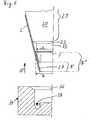
- the cups 1 showneach have a heat-insulating outer jacket 17 which partially surrounds the jacket 2 delimiting the interior space 5, forming a cavity 18.
- Such cupsare also referred to as double-walled insulating cups, in which the jacket 2 located inside the outer jacket 17 in connection with the base 3 can also be referred to as an "inner cup”.
- the first means 7 for holding another cup 1 'of the same type and the second means 9 for holdingare each analogous to that in FIG Figure 1 described variant designed so that a repeated description can be dispensed with.
- the outer jacket 17 of the in Figure 4The cup 1 shown is arranged essentially parallel to the jacket 2 delimiting the interior space.
- the outer jacket 17has an inwardly directed curl 19 and 20 at an upper and a lower end and is supported by the curls 19 and 20 on the jacket 2 delimiting the interior space 5. It can be provided that the outer jacket 17 is fixed in the area of the curl 19 and / or 20, for example by gluing.
- the curl 20is supported in the area of the frame 4 and thus below the horizontal bottom 3 of the inner cup on the inner casing 5, whereby the outer casing 17 is very stable.
- the outer jacket 17also covers the first means 7 for holding, so that it cannot be seen from the outside.
- the curl 20has a region 23 running parallel to the outer jacket 17.
- the area 23runs close to the inside of the outer jacket 17 and can also rest there.
- the area 23 running parallel to the outer jacket 17simplifies the sliding of the outer jacket 17 onto the jacket 2, since the outer jacket 17 can no longer get stuck on the frame 4.
- the jacket 2 delimiting the inner space 5has an abrupt change in size in the area below the lip curl 6 in the form of a shoulder 21, which, viewed from the bottom 3 to the lip curl 6, presents itself as an abrupt cross-sectional widening.
- the outer jacket 17is connected in the area between the lip curl 6 and the shoulder 21 to the jacket 2 delimiting the interior space 5, for example by sealing or gluing.
- the outer jacket 17has an inwardly directed curl 20, which also has a region 23 running parallel to the outer jacket 17.
- the curling 20is supported on the frame 4 below the bottom 3.
- the curl 20is in contrast to Figure 4 pressed flat and slightly indented at the lower edge area 24 of the outer jacket 17, so that there is a greater conicity of the outer jacket 17 there.
- the cup 1can also be designed differently in the area of the shoulder 21.
- An advantageous variant in the area of the shoulder 21is shown in FIG Figure 5A shown greatly enlarged.
- the area of the jacket 2 delimiting the interior space 5, which lies between the lip curl 6 and the shoulder 21 and in Figure 5Ais designated by the reference numeral 25, shows in contrast to the representation Figure 5 a different angle of inclination to the central axis 13 than the rest of the shell 2.
- the area 25 of the jacket 2runs between the lip curl 6 and the shoulder 21 approximately parallel to the central axis 13. So that the outer jacket 17 can be pushed a little under the lip curl 6 when it is pushed onto the inner cup 1, the upper edge area 26 of the outer jacket 17 is slightly indented.
- the edge region 26therefore does not continue the conical outer jacket 17 uniformly, but rather has a slightly decreasing diameter. If the outer jacket 17, as in Figure 5A , shown, with its upper edge pushed a little into the lip curl 6, the result is a particularly good appearance of the cup 1, since the upper edge of the outer jacket 17 is no longer visible. If the outer jacket 17 is pushed further into the top curl 6 in an embodiment not shown, the clamping of the outer jacket 17 by the material of the top curl 6 already causes the outer jacket 17 to be fixed single attachment of the outer jacket 17 will be sufficient.
- the bead 8 of the first means 7 for holding the cupsis adapted to the dimension Y of the second means 9 for holding another cup 1 'of the same type. If the dimensions X and Y for the cups 1 of the Figures 4 and 5 with the different outer shells 17 are identical, all these cups 1 can also be stacked with one another in any combination without jamming, since all outer shells 17 lie within the space 16 between the parallel lines 15 and the shell 2 forming the interior 5.
- the outside 22 of the outer sheaths 17can have different structures.
- the outside 22can for example be corrugated, embossed, corrugated or have a foamed coating. Provision can also be made for the outer jacket 17 to be made corrugated, for example, and also to provide a smooth cover for the corrugated structure in the form of a further jacket on the outside 22 in order to further improve the insulating effect of the cup 1.
- the design of the outer jacket 17 with an upper curl 19 or the fastening of the outer jacket 17 in the area of a shoulder 21 of the jacket 2have the advantage that a very wide cavity 18 between the jacket 2 and the outer jacket 17 even in an area just below the top curl 6 arises, which has a very high insulating effect.
- the curl 19 or the shoulder 21ensure, even without additional means, such as foamed layers or corrugated cardboard layers within the cavity 18, that the distance between the jacket 2 and the outer jacket 17 does not decrease even under pressure, for example from a grasping hand Isolation effect is lost.
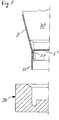
- a conical outer shell 2 and an approximately pot-shaped bottomare first formed.
- the outer casing 2initially has the shape of a conical sleeve and the base 3 has the shape of a truncated cone which tapers parallel to the outer sleeve 2.
- the base 3 and the outer casing 2are not yet connected to one another, but merely plugged into one another.
- the outer jacket 2is placed on a mandrel 30, which has a frustoconical shape in a first area 29, but in which the tapered end of the frustoconical area 29 is followed by a further frustoconical surface 32, which tapers more and which is to be formed the bead 8, see Fig. 1 , is provided.
- a circular cylinder-shaped region 33adjoins the surface 32 and the base 3 then rests on the free end thereof.
- a diameter E of this circular cylindrical area 33can be smaller, in particular about 0.5 mm smaller, than the diameter D of the base, see also Fig. 1 .
- the outer casing 2can be compressed somewhat more to form the bead 8 than would be possible with the casing 2 and the base 3 already sealed. Since the jacket 2 as well as the bottom 3 are made of coated paper material, the bottom 3 can be at least slightly compressed. This makes it possible to pull the bead 8 relatively far into the interior of the cup in order to ensure that several cups can be safely stacked.
- a molding tool 34which is shown in FIG Fig. 6 is shown, and that in the direction of arrow 35 upwards, in Direction of the mandrel 30 is driven.
- the molding tool 34has a truncated conical surface 36, the conicity of which essentially corresponds to the surface 32 on the mandrel 30.
- the outer sleeve 2is thus clamped between the mandrel 30 and the molding tool 34 and the bead 8 is formed between the surfaces 32 and 36.
- the molding tool 34has a channel-shaped region 38 which, in the sectional view of the molding tool 34 in FIG Fig. 6 is only shown in sections, but extends over 360 °.
- the simultaneous turning over of the lower edge 37 of the casing 2 with the shaping of the bead 8considerably facilitates the production of the cup according to the invention.
- the jacket 2is wound from a circular ring segment over a mandrel and then glued or sealed along a longitudinal seam.
- the longitudinal seam of the casing 2 in the area of the lower end 37cannot be glued or sealed.
- This areais in the representation of the Fig. 6 denoted by F. If the longitudinal seam in the area F is not glued or sealed, the jacket 2 can deform more freely when the lower end 37 is turned over and the formation of waves in the paper material, which in principle is difficult to deform, is avoided.
- the area Fcan even extend from the lower edge 37 of the casing 2 to the lower edge of the base 3, as in FIG Fig. 6 is also indicated by the reference number F '.
- the length F or F 'is thus variable and can be changed.
- the base 3is connected to the casing 2 to form the frame 4 in order to complete the inner cup 1.
- the frame 4is expanded at the same time when the base 3 is connected to the casing 2, so that the in Fig. 1
- FIG. 7shows a further embodiment of the invention, in contrast to the embodiment of Fig. 6 the shell 2 'initially has a conical shape, which then merges into a cylindrical shape at the horizontal bottom 3'.
- the bottom 3 ′consequently has an inverted pot shape with a cylindrical circumferential wall 31.
- Both the design of the mandrel 30 and of the molding tool 34are, however, in accordance with the shape already explained Fig. 6 identical.
- the cylindrical preforming of the circumferential wall 31 of the base 3 'and the likewise cylindrical preforming of the lower area of the casing 2'reduce the formation of creases when the lower edge 37 'of the casing 2' is folded over and during the subsequent expansion and formation of the frame 4.
- either only the jaws 39 or the ring 38 or both the inner jaws 39 and the outer ring 38can be heated, so that at the same time as the cup-shaped wall 31 is widened, the three layers of material that then lie on top of one another are settled on one another and thereby form the frame 4.
- a radially outwardly facing surface of the inner jaw 39is arranged parallel to the inner surface of the outer ring 38 and also has the angle at which the frame 4 is to be arranged in the final state,
- the inner jaws 39are, for example, part of a mandrel and can be moved by moving an in Fig. 6 not shown central part are moved radially outward.
- the outer ring 38can be designed as a fixed ring or, for example, also as an openable ring in order to make it easier to slide it onto the jacket 2 '.
- a rotating rollercan also be provided, for example, which exerts a force directed radially outward in the direction of the outer ring 38 on the edge 37 ′ and the wall 31 in order to form the frame 4. While the frame 4 is being formed, the cup remains on the mandrel 30.
- the inner cup 1is finished and can be removed from the mandrel 30.
- FIG Fig. 4, Fig. 5an outer jacket 17 pushed on. This is done in such a way that the outer jacket 17 is received in a ring-like outer tool and a pilot mandrel with a suction head then extends through the tapered end of the outer jacket 17. This suction head engages an inner cup 1 from below on the bottom 3, sucks it and pulls it into the tapered outer jacket 17 until the into the Figures 4 and 5 is reached.
- the outer jacket 22To produce the outer jacket 22, it is first wound from a circular segment-shaped blank on a mandrel and into a frustoconical one Sleeve connected. In the area of the lower, tapered end, according to Fig. 9 first a curl 40 vorgefomt.
- This curling 40represents a preliminary stage of the curling 20, as shown in FIG Figures 4 and 5 is shown.
- the curl 40is then pressed flat until the in Fig. 10 shown form of curling is achieved. It can be seen that the lower edge of the outer jacket 17, which is formed by the curl 20, is slightly drawn in and therefore has a greater conicity at the lower end, as has already been discussed.
- the Fig. 9In the representation of the Fig.
- a knurling or corrugation 41is indicated on the inside of the curl 20.
- Such a knurling or corrugation 41 on the inside of the curl 20can be provided in order to achieve greater elasticity when the outer jacket 17 is pushed onto the inner cup 1.
- an inner diameter V of the curl 20is smaller than an outer diameter Y, see Fig. 5 the frame 4.
- the end of the outer jacket 17 with the curl 20must therefore widen slightly in order to be able to be pushed over the frame 4. This expansion is facilitated by the knurling or corrugation 41.
- the longitudinal seam of the outer jacket 17 in the area of the curl 20cannot be glued or sealed. This facilitates a certain opening of the outer jacket 17 in the area of the curl 20, so that the outer jacket 17 can be pushed over the frame 4 and then contracts again, so that the curl 20 in the FIG Fig. 5 position shown on the outside of the frame 4 rests.
- a diameter U at the upper end of the curl 20is greater than the outer diameter Y of the frame 4.
- Fig. 5refers to. Since the inner diameter of the outer jacket 17 at the upper edge of the curl 20 is greater than the outer diameter Y, this upper edge of the curl 20 cannot get caught on the frame 4 when it is pushed onto the frame 4. Instead, the frame 4 runs onto the slope that is formed by the inside of the curl 20 and when the outer jacket 17 is pushed on further, it is expanded, slips over the area with the largest diameter Y of the frame 4 and then takes the in Fig. 5 position shown. It can be seen that the outer jacket 17 is then also held on the inner cup 1 by the internal stress, since in order to remove the outer jacket 17 it would have to be pulled over the conically widening frame 4 again.
Landscapes
- Engineering & Computer Science (AREA)
- Mechanical Engineering (AREA)
- Stackable Containers (AREA)
- Packages (AREA)
- Making Paper Articles (AREA)
- Table Devices Or Equipment (AREA)
- Details Of Rigid Or Semi-Rigid Containers (AREA)
Description
Translated fromGermanDie Erfindung betrifft einen Becher aus einem Papiermaterial mit einem befüllbaren Innenraum, der durch einen konischen Mantel und einen Boden gebildet wird, wobei der Boden am unteren Ende des Innenraums mit einer Zarge im Wesentlichen flüssigkeitsdicht am Mantel befestigt ist, wobei der Mantel und/oder der Boden im Bereich der Zarge und/oder die Zarge selbst wenigstens in einem Bereich des Umfangs eine nach außen ragende Aufweitung aufweist und wobei ein unterer Rand der Aufweitung eine Standfläche für den Becher bildet und wobei der Becher einen Außenmantel aufweist.The invention relates to a cup made of a paper material with a fillable interior, which is formed by a conical jacket and a base, the base at the lower end of the interior being fastened to the jacket with a frame in a substantially liquid-tight manner, the jacket and / or the The bottom in the area of the frame and / or the frame itself has an outwardly protruding widening at least in one area of the circumference and wherein a lower edge of the widening forms a standing surface for the cup and the cup has an outer jacket.
Die Erfindung betrifft ferner ein Verfahren zum Herstellen eines Bechers aus einem Papiermaterial, der aus einem konischen Mantel und einem im Bereich des geringeren Umfangs des Mantels durch eine Zarge befestigten Boden besteht, wobei der Boden mit dem Mantel unter Bildung einer Zarge verbunden wird und wobei während der Bildung der Zarge der Mantel und/oder der Boden im Bereich der Zarge und/oder die Zarge selbst wenigstens in einem Bereich entlang des Umfangs nach außen aufgeweitet wird, so dass ein unterer Rand der Aufweitung eine Standfläche für den Becher bildet.The invention further relates to a method for producing a cup from a paper material, which consists of a conical shell and a base fastened by a frame in the region of the lesser circumference of the shell, the base being connected to the shell to form a frame and during the formation of the frame, the casing and / or the base in the area of the frame and / or the frame itself is widened outwards at least in one area along the circumference, so that a lower edge of the widening forms a standing surface for the cup.
Ein Becher dieser Art ist durch die
Bei dem bekannten Becher umschließt der Außenmantel vollständig die Zarge, so dass diese von außen nicht mehr sichtbar ist. Beim Einschlagen und Befestigen des Außenmantels von innen an der Zarge ist deshalb ein Gegenhalten von außen nicht mehr möglich. Der Außenmantel kann nur mit einer sehr geringen Kraft, die die Zarge selbst aufnehmen kann, von innen angedrückt werden. Ist die Andruckkraft zu hoch, kann die Zarge reißen, andererseits kann die Befestigung des Außenmantels mangelhaft sein, wenn die Andruckkraft zu gering ist. Bei einem Verbinden des Außenmantels durch Heißsiegeln kann es vorkommen, dass sich die Versiegelung zwischen Boden und dem den Innenraum begrenzenden Mantel wieder löst, da beim Siegeln des nach innen eingeschlagenen Außenmantels kein Gegendruck an der Zarge von außen mehr ausgeübt werden kann.In the known cup, the outer jacket completely encloses the frame so that it is no longer visible from the outside. When hammering in and attaching the outer jacket to the frame from the inside, counter-holding from the outside is no longer possible. The outer jacket can only be pressed on from the inside with a very small amount of force, which the frame itself can absorb. If the pressure is too high, the frame can tear; on the other hand, the attachment of the outer jacket can be inadequate if the pressure is too low. When the outer jacket is connected by heat sealing, it can happen that the seal between the bottom and the jacket delimiting the interior is loosened again, since no counter-pressure can be exerted on the frame from the outside when the inwardly folded outer jacket is sealed.
Bei Bechern aus Papiermaterial ist die Zarge ein sehr wichtiges Element des Bechers. Die Zarge ist notwendig für die Verbindung zwischen dem Mantel und dem Boden. An der Zarge liegen wenigstens zwei Materialschichten in Dickenrichtung aufeinander, nämlich das Material des Bodens und das Material des den Innenraum begrenzenden Mantels. Bevorzugt ist der Boden topfförmig gestaltet, dessen offene Seite der Füllöffnung des Bechers abgewandt ist. Die wenigstens zwei Materialschichten sind also bevorzugt entlang der Wandung des topfförmigen Bodens angeordnet. Es kann zusätzlich vorgesehen sein, dass beispielsweise der Mantel um das Material des Bodens herum eingeschlagen ist, und dass die Zarge aus drei oder mehr Materialschichten besteht. Das Material des Bodens ist mit dem Material des Mantels im Bereich der Zarge verklebt oder versiegelt, um wenigstens für einen gewissen Zeitraum flüssigkeitsdicht zu sein.For cups made of paper material, the frame is a very important element of the cup. The frame is necessary for the connection between the jacket and the floor. At least two material layers lie on top of one another in the thickness direction on the frame, namely the material of the base and the material of the jacket delimiting the interior space. The base is preferably designed in the shape of a pot, the open side of which faces away from the filling opening of the cup. The at least two material layers are therefore preferably arranged along the wall of the pot-shaped base. It can also be provided that, for example, the jacket is wrapped around the material of the floor, and that the frame consists of three or more layers of material. The material of the bottom is glued or sealed to the material of the jacket in the area of the frame in order to be liquid-tight for at least a certain period of time.
Unter dem Begriff "Papiermaterial" aus dem der Boden und der Mantel besteht, können dabei unterschiedliche Materialien verstanden werden, die wenigstens eine Schicht aus Papier, Pappe oder Karton aufweisen. Zusätzlich kann das Material eine oder mehrere Schichten aus Kunststoff und/oder Aluminium aufweisen. Es kann auch vorgesehen sein, dass das Papiermaterial gewachst oder lackiert ist, um eine Beständigkeit gegenüber der in den Innenraum einzufüllenden Flüssigkeit aufzuweisen. Bevorzugt ist das Papiermaterial wenigstens auf der den Innenraum begrenzenden Seite mit einer dünnen Kunststoffschicht, vorzugsweise aus Polyethylen, beschichtet. Im Gegensatz zu reinem Kunststoffmaterial ist die Formbarkeit und insbesondere die Dehnbarkeit von derartigem Papiermaterial eingeschränkt. Bei zu starker Verformung kann das Papiermaterial selbst oder auch eine vorgesehene Beschichtung reißen, so dass die Dichtigkeit beeinträchtigt ist. Bei Bechern aus Papiermaterial ist deshalb die Zarge ein wesentliches Konstruktionsmerkmal, auf das nicht verzichtet werden kann.The term "paper material" from which the base and the jacket are made can be understood to mean different materials which have at least one layer of paper, cardboard or cardboard. In addition, the material can have one or more layers of plastic and / or aluminum. It can also be provided that the paper material is waxed or lacquered in order to be resistant to the liquid to be filled into the interior. The paper material is preferably coated with a thin plastic layer, preferably made of polyethylene, at least on the side delimiting the interior space. In contrast to pure plastic material, the formability and in particular the ductility of such paper material is limited. If the deformation is too great, the paper material itself or a coating provided can tear, so that the tightness is impaired. In the case of cups made of paper material, the frame is therefore an essential design feature that cannot be dispensed with.
Aus der japanischen Patentzusammenfassung
Aus der französischen Patentschrift
Aus der britischen Patentschrift
Der Erfindung liegt die Aufgabe zu Grunde, die Herstellbarkeit eines Bechers der eingangs genannten Art zu vereinfachen und Dichtigkeitsprobleme an der Zarge zu vermeiden.The invention is based on the object of simplifying the manufacturability of a cup of the type mentioned at the beginning and of avoiding sealing problems on the frame.
Die Aufgabe wird durch einen Becher mit den Merkmalen von Anspruch 1 gelöst.The object is achieved by a cup with the features of claim 1.
Die Aufgabe wird bei dem Verfahren durch die Merkmale von Anspruch 8 gelöst.The object is achieved in the method by the features of claim 8.
Die Standfläche des Bechers ist durch die Aufweitung vergrößert, so dass der Becher eine verbesserte Standfestigkeit aufweist. Die Aufweitung wird dabei nicht oder nicht vollständig durch einen Außenmantel abgedeckt, so dass das Material des Mantels oder des Bodens unmittelbar die Standfläche bildet. Die Zarge kann dadurch in ihrer Dichtigkeit nicht durch die Anbringung des zusätzlichen Materials des Außenmantels beeinträchtigt werden. In bevorzugter Ausgestaltung ist die Aufweitung durchgehend und gleichmäßig entlang des Umfangs geformt. Wenn das Papiermaterial beschichtet ist, ist es vorteilhaft, die Aufweitung nur so groß zu formen, dass die Beschichtung nicht einreißt.The footprint of the cup is enlarged by the widening, so that the cup has improved stability. The widening is not or not completely covered by an outer jacket, so that the material of the jacket or the base directly forms the standing surface. As a result, the tightness of the frame cannot be impaired by the attachment of the additional material of the outer jacket. In a preferred embodiment, the widening is formed continuously and uniformly along the circumference. If the paper material is coated, it is advantageous to form the widening only so large that the coating does not tear.
Bevorzugt wird die Zarge auf ihrer gesamten Höhe aufgeweitet. Die Zarge weist dann - in einem Axialschnitt gesehen - einen im Wesentlichen konstanten Neigungswinkel zu der Mittelachse des Bechers auf. In Ausgestaltung kann jedoch auch vorgesehen sein, dass die Zarge unterschiedliche Höhenbereiche enthält, die unterschiedliche Neigungswinkel aufweisen. Dabei kann der an den Boden angrenzende Bereich der Zarge in seiner ursprünglichen Form verbleiben, während der untere Rand der Zarge vermehrt aufgeweitet wird. Der obere Höhenbereich kann hauptsächlich zur Abdichtung des befüllbaren Innenraums dienen und verbindet den konischen Mantel im Wesentlichen flüssigkeitsdicht mit dem Boden. In diesem oberen Höhenbereich sind der Mantel und die Wandung aneinander angesiegelt oder verklebt. Im unteren Höhenbereich der Zarge ist das Material des den Innenraum begrenzenden Mantels und/oder die Wandung des Bodens aufgeweitet und bildet mit seinem unteren Rand eine vergrößerte Standfläche für den Becher. In diesem Höhenbereich ist eine flüssigkeitsdichte Verbindung zwischen dem Material des Bodens und dem Material des Mantels nicht mehr unbedingt erforderlich, so dass ein Siegeln oder Verkleben im unteren Höhenbereich wenigstens teilweise entfallen kann.The frame is preferably widened over its entire height. The frame then has - seen in an axial section - an essentially constant angle of inclination to the central axis of the cup. In an embodiment, however, it can also be provided that the frame contains different height areas which have different angles of inclination. The area of the frame adjoining the bottom can remain in its original shape, while the lower edge of the frame is widened to a greater extent. The upper height area can mainly serve to seal off the fillable interior space and connects the conical jacket to the floor in a substantially liquid-tight manner. In this upper height range, the jacket and the wall are sealed or glued to one another. In the lower height area of the frame, the material of the jacket delimiting the interior space and / or the wall of the base is widened and, with its lower edge, forms an enlarged standing surface for the cup. In this height range, a liquid-tight connection between the material of the base and the material of the casing is no longer absolutely necessary, so that sealing or gluing in the lower height range can at least partially be dispensed with.
Der erfindungsgemäße Becher lässt sich sehr vielseitig einsetzen, da er sowohl ohne Außenmantel als auch mit verschiedenen Außenmänteln eingesetzt werden kann. Bevorzugt ist ein wärmeisolierender Mantel vorgesehen, der den den Innenraum begrenzenden Mantel teilweise unter Bildung eines Hohlraumes umgibt. Der Außenmantel wird dabei bevorzugt auf den den Innenraum begrenzenden konischen Mantel entlang der Mittelachse aufgeschoben und fixiert, nachdem die Zarge geformt und aufgeweitet wurde.The cup according to the invention can be used in a very versatile manner, since it can be used both without an outer jacket and with different outer jackets. A heat-insulating jacket is preferably provided which partially surrounds the jacket delimiting the interior space, forming a cavity. The outer casing is preferably pushed onto the conical casing delimiting the interior space along the central axis and fixed after the frame has been shaped and widened.
Die Aufweitung an der Zarge lässt sich sehr vorteilhaft einsetzen, um die Stapeleigenschaften des Bechers zu verbessern. Ein stapelbarer Becher ist beispielsweise durch die
Der bekannte Becher hat den Nachteil, dass die beim Stapeln auftretenden Kräfte, über den den Innenraum begrenzenden Mantel und über den Außenmantel übertragen werden. Die Kräfte, die innerhalb des Bechers von dem ersten Mittel zum Halten an das zweite Mittel zum Halten weitergeleitet werden müssen, werden zuerst durch den den Innenraum begrenzenden Mantel zu der Verbindungsstelle zwischen Innenmantel und Außenmantel übertragen und über diese Verbindungsstelle an den Außenmantel weitergegeben. Im Außenmantel werden die Kräfte dann zu dem als Einrollung ausgebildeten zweiten Mittel zum Halten weitergeleitet und dort an den nächsten Becher übertragen. Hierdurch müssen sowohl der Innenmantel als auch der Außenmantel stabil genug ausgelegt sein, um die auftretenden Kräfte aufnehmen zu können. Außerdem muss auch die Verbindungsstelle zwischen dem Außenmantel und dem Innenmantel auf die maximal auftretenden Kräfte ausgelegt sein.The known cup has the disadvantage that the forces occurring during stacking are transmitted via the jacket delimiting the interior space and via the outer jacket. The forces that have to be passed on within the cup from the first holding means to the second holding means are first transmitted through the jacket delimiting the interior space to the connection point between the inner jacket and the outer jacket and passed on to the outer jacket via this connection point. In the outer jacket, the forces are then passed on to the second holding means, which is designed as a curl, and there they are transferred to the next cup. As a result, both the inner jacket and the outer jacket must be designed to be stable enough to be able to absorb the forces that occur. In addition, the connection point between the outer jacket and the inner jacket must also be designed for the maximum forces that occur.
Die Gestaltungsfreiheit des Bechers nach der
Bei dem Becher gemäß der vorliegenden Erfindung ist vorgesehen, dass an der Zarge ein Mittel zum Halten eines anderen Bechers gleicher Art angeordnet ist, das bei einem Stapeln des Bechers mit einem gleichartigen Becher zusammenwirken kann. Das Mittel zum Halten wird vorteilhafterweise durch die Aufweitung gebildet. Bevorzugt ist vorgesehen, dass an dem den Innenraum begrenzenden Mantel ein erstes Mittel zu Halten angeordnet ist, dass bei einem Stapeln des Bechers mit einem an der Aufweitung eines gleichartigen Bechers angebrachten zweiten Mittel zum Halten zusammenwirken kann.In the case of the cup according to the present invention it is provided that a means for holding another cup of the same type is arranged on the frame, which means can cooperate with a similar cup when the cup is stacked. The means for holding is advantageously formed by the widening. Provision is preferably made for a first holding means to be arranged on the jacket delimiting the interior space, so that when the cup is stacked, it can interact with a second holding means attached to the widening of a similar cup.
Der stapelbare Becher wird bevorzugt durch ein Verfahren mit den folgenden Verfahrensschritten hergestellt:
- Formen wenigstens eines ersten Mittels zum Halten eines anderen Bechers gleicher Art an dem den Innenraum begrenzenden Mantel;
- Formen eines zweiten Mittels zum Halten an der Zarge, das bei einem Stapeln des Bechers mit einem an einem gleichartigen Becher gebrachten ersten Mittel zum Halten zusammenwirken kann.
- Forming at least one first means for holding another cup of the same type on the jacket defining the interior space;
- Forming a second means for holding on the frame, which, when the cup is stacked, can cooperate with a first holding means which is attached to a similar cup.
Das zweite Mittel zum Halten ist dabei an dem den Innenraum begrenzenden Mantel oder an dem Boden oder an einer Zarge angeordnet, durch die der den Innenraum begrenzende Mantel mit dem Boden verbunden ist. Jedenfalls ist das zweite Mittel zum Halten an einer Komponente des Bechers angebracht, die mit dem befüllbaren Innenraum in Kontakt steht.The second means for holding is arranged on the jacket delimiting the interior space or on the floor or on a frame through which the jacket delimiting the interior space is connected to the floor. In any case, the second means for holding is attached to a component of the cup which is in contact with the interior space that can be filled.
Der erfindungsgemäße Becher hat den Vorteil, dass er auch ohne Vorhandensein eines Außenmantels sicher und stabil gestapelt und ohne Verklemmen auch wieder entstapelt werden kann. Falls vorgesehen ist, dem Becher einen wärmeisolierenden Außenmantel zuzuordnen, so lässt sich dieser weitgehend unabhängig und frei von den beim Becher der
Um ein Verklemmen mehrerer Becher beim Stapeln zu verhindern, ist es vorteilhaft, dass die Abmessungen des zweiten Mittels zum Halten an die Abmessungen des ersten Mittels zum Halten eines anderen Bechers gleicher Art angepasst sind. Das erste Mittel zum Halten eines anderen Bechers gleicher Art kann dabei an sich beliebig ausgeformt sein. Wesentlich ist, dass eine Kontur geformt wird, die in axialer Richtung des Bechers wirkende Kräfte, also der Kräfte, die beim Stapeln zwischen zwei Bechern wirken, aufnehmen kann. Das erste Mittel zum Halten ist bevorzugt als eine Sicke oder Rippe ausgestaltet, die wenigstens in einem Bereich entlang des Umfangs in den den Innenraum begrenzenden Mantel eingeformt ist. Die Sicke oder Rippe kann dabei entlang des Umfangs durchgehend oder mit Unterbrechungen gestaltet sein.In order to prevent several cups from jamming when stacking, it is advantageous that the dimensions of the second means for holding are adapted to the dimensions of the first means for holding another cup of the same type. The first means for holding another cup of the same type can be shaped as desired. It is essential that a contour is formed that can absorb forces acting in the axial direction of the cup, that is to say the forces that act between two cups when they are stacked. The first means for holding is preferably designed as a bead or rib which is molded into the jacket delimiting the interior space at least in one area along the circumference. The bead or rib can be designed continuously or with interruptions along the circumference.
Wenn nun in Ausgestaltung der Erfindung vorgesehen ist, dass der Becher einen wärmeisolierenden Außenmantel aufweist, ist dabei die Ausgestaltung des wärmeisolierenden Außenmantels an sich beliebig. Der Außenmantel kann beispielsweise aus einem Kunststoff-Papier- oder Verbundmaterial hergestellt sein. Zur Verbesserung der Isolationswirkung kann der Außenmantel auch gewellt, geriffelt, geprägt oder mit einer aufgeschäumten Schicht versehen sein. Der Außenmantel kann auch mehrschichtig ausgebildet sein, beispielsweise kann eine gewellte Zwischenschicht vorgesehen sein, die von einer glatt darüber gelegten Außenschicht abgedeckt ist. Dadurch, dass der erfindungsgemäße Becher unabhängig vom Außenmantel gestapelt werden kann, lässt sich ein und derselbe Innenbecher in einfacher und nahezu beliebiger Weise mit den unterschiedlichsten Außenmänteln kombinieren. Ohne die Form und Abmaße des Innenbechers bzw. der den befüllbaren Innenraum bildenden Komponenten zu verändern, lassen sich verschiedene Becher mit unterschiedlichem optischen und haptischen Erscheinungsbild schaffen, da das Erscheinungsbild, das der Benutzer des Bechers wahrnimmt, hauptsächlich durch die Gestaltung des Außenmantels bestimmt wird.If, in an embodiment of the invention, it is provided that the cup has a heat-insulating outer jacket, the heat-insulating outer jacket can be configured as desired. The outer jacket can be made from a plastic, paper or composite material, for example. To improve the insulation effect, the outer jacket can also be corrugated, corrugated, embossed or provided with a foamed layer. The outer jacket can also have a multilayer design, for example a corrugated intermediate layer can be provided, which is covered by an outer layer laid smoothly over it. Because the cup according to the invention can be stacked independently of the outer casing, one and the same inner cup can be combined in a simple and almost arbitrary manner with a wide variety of outer casings. Without changing the shape and dimensions of the inner cup or the components forming the fillable interior, different cups with different optical and haptic appearances can be created, since the appearance that the user of the cup perceives is mainly determined by the design of the outer shell.
Bei einem Verfahren zum Herstellen eines doppelwandigen Bechers werden vorteilhafterweise folgende Verfahrensschritte ausgeführt:
- Formen wenigstens eines ersten Mittels zum Halten eines anderen Bechers gleicher Art an dem den Innenraum begrenzenden Mantel;
- Formen einer aufgeweiteten Zarge und Verpressen von dem den Innenraum begrenzenden Mantel und dem Boden;
- Formen eines zweiten Mittels zum Halten an der Zarge, das bei einem Stapeln des Bechers mit einem an einem gleichartigen Becher angebrachten ersten Mittel zum Halten zusammenwirken kann;
- Aufschieben eines hülsenförmig vorgeformten Außenmantels auf den den Innenraum begrenzenden konischen Mantel in axialer Richtung; Fixieren des Außenmantels an dem den Innenraum begrenzenden Mantel.
- Forming at least one first means for holding another cup of the same type on the jacket defining the interior space;
- Forming a widened frame and pressing of the jacket delimiting the interior space and the base;
- Forming a second means for holding on the frame, which, when the cup is stacked, can cooperate with a first means for holding which is attached to a similar cup;
- Sliding a sleeve-shaped preformed outer jacket onto the conical jacket delimiting the interior space in the axial direction; Fixing the outer jacket on the jacket delimiting the interior space.
Das Fixieren des Außenmantels an dem Innenbecher kann dabei beispielsweise durch Siegeln oder Leimen geschehen. Es bewirkt eine sichere Verbindung zwischen dem Außenmantel und dem den Innenraum begrenzenden Mantel, so dass ein Verrutschen des Außenmantels sicher verhindert wird, auch wenn der Außenmantel nur eine geringe Höhe hat.The outer jacket can be fixed to the inner cup, for example, by sealing or gluing. It creates a secure connection between the outer jacket and the jacket delimiting the interior space, so that the outer jacket is reliably prevented from slipping, even if the outer jacket is only low in height.
Um ein gutes äußeres Erscheinungsbild des Bechers zu erreichen, ist es vorteilhaft, dass der Außenmantel unterhalb des ersten Mittels zum Halten eines anderen Bechers gleicher Art oder sogar unterhalb des Bodens endet. Das an dem Innenmantel angebrachte erste Mittel zum Halten wird dadurch von dem Außenmantel überdeckt und ist von außen nicht mehr sichtbar. Des Weiteren ist es vorteilhaft, dass der Außenmantel oberhalb der Aufweitung der Zarge endet.In order to achieve a good external appearance of the cup, it is advantageous that the outer casing ends below the first means for holding another cup of the same type or even below the bottom. The first holding means attached to the inner jacket is thereby covered by the outer jacket and is no longer visible from the outside. Furthermore, it is advantageous that the outer jacket ends above the widening of the frame.
Bevorzugt wird die Aufweitung an der Zarge durch ein Zusammenwirken eines außerhalb und innerhalb der Zarge angeordneten Werkzeuges erfolgen. Die Aufweitung lässt sich dadurch sehr präzise formen.The expansion on the frame is preferably carried out by the interaction of a tool arranged outside and inside the frame. The widening can thereby be shaped very precisely.
Die Aufweitung ist vorteilhafterweise so weit nach außen aufgeweitet, dass eine an dem unteren Rand der Aufweitung angelegte Parallele zu dem den Innenraum begrenzenden Mantel mit einem gewissen Abstand außerhalb des den Innenraum begrenzenden Mantels verläuft. Damit ein vorgesehener Außenmantel das Stapeln des Bechers nicht behindert, ist es vorteilhaft, dass sich die Außenkontur des Außenmantels innerhalb der Parallelen zu dem den Innenraum begrenzenden Mantel befindet, die an der Aufweitung der Zarge angelegt wird.The widening is advantageously widened outward so far that a parallel to the jacket delimiting the interior space, which is applied to the lower edge of the widening, runs at a certain distance outside the jacket delimiting the interior space. So that a provided outer jacket does not hinder the stacking of the cup, it is advantageous that the outer contour of the outer jacket is located within the parallels to the jacket delimiting the interior, which is placed on the widening of the frame.
Weitere Vorteile und Merkmale der Erfindung ergeben sich aus den Ansprüchen und der nachfolgenden Beschreibung einiger Ausführungsbeispiele im Zusammenhang mit den Figuren. Einzelmerkmale der unterschiedlichen dargestellten und beschriebenen Ausführungsformen lassen sich dabei in beliebiger Weise kombinieren, ohne den Rahmen der Erfindung zu überschreiten.Further advantages and features of the invention emerge from the claims and the following description of some exemplary embodiments in connection with the figures. Individual features of the different illustrated and described embodiments can be combined in any way without going beyond the scope of the invention.
Es zeigen:
Figur 1 einen erfindungsgemäßen Becher im Längsschnitt,Figur 2Figur 1 auf zwei gestapelte Becher,Figuren 3 A bis C schematisch und nur teilweise dargestellte Längsschnitte auf unterschiedliche Ausgestaltungsformen im Bereich der Zarge von erfindungsgemäßen Bechern,Figur 4 und 5Figur 1 auf teilweise dargestellte Becher unterschiedlicher Ausgestaltung, bei denen verschiedene Außenmäntel vorgesehen sind,Figur 5A eine vergrößerte Ansicht auf eine Variante derFigur 5 ,Figur 6Figur 7Figur 6Figur 8 einen Längsschnitt durch die Zarge eines erfindungsgemäßen Bechers mit einem Innenwerkzeug und einem Außenwerkzeug zum Verpressen der Zarge,Figur 9 und 10Figur 5 in unterschiedlichen Herstellungsschritten.
Figure 1 a cup according to the invention in longitudinal section,Figure 2 a view similarFigure 1 on two stacked cups,Figures 3 A to C schematically and only partially shown longitudinal sections of different embodiments in the area of the frame of cups according to the invention,Figures 4 and 5 Views similarFigure 1 on partially shown cups of different designs, in which different outer shells are provided,Figure 5A an enlarged view of a variant of theFigure 5 ,Figure 6 a longitudinal section of a cup in the area of the frame when hammering in the jacket and when forming a means for holding another cup,Figure 7 a view of a variant of theFigure 6 ,Figure 8 a longitudinal section through the frame of a cup according to the invention with an inner tool and an outer tool for pressing the frame,Figures 9 and 10 a partially shown outer jacket of the cup ofFigure 5 in different manufacturing steps.
Der in
Die Eigenschaft "konisch" des Mantels 2 ist dabei so zu verstehen, dass sich der Mantel 2 in dem in
Die Zarge 4 weist wenigstens in einem Bereich entlang ihres Umfanges eine nach außen ragende Aufweitung 10 auf. Unter Aufweitung ist dabei zu verstehen, dass die Zarge 4 bezogen auf einen Kreiszylinder um die Mittelachse 13 nach außen ausgestellt ist, so dass die Zarge 4 eine sich nach unten, zur Standfläche hin erweiternde Querschnittsfläche einschließt. Ein unterer Rand 14 der Aufweitung 10 an der Zarge 4 bildet die Standfläche für den Becher 1. Der Becher 1 steht bei Gebrauch auf seiner Standfläche, die durch die Aufweitung 10 vergrößert ist. Dadurch ist ein Umkippen des Bechers 1 erschwert. Die Aufweitung 10 ist bevorzugt entlang des Umfangs der Zarge 4 umlaufend gestaltet.The
Die nach außenragende Aufweitung 10 bildet auch ein Mittel 9 zum Halten eines anderen Bechers 1' gleicher Art, das bei einem Stapeln des Bechers 1 mit einem gleichartigen Becher 1' zusammenwirken kann. Das Stapeln des Bechers 1 in einem gleichartigen Becher 1' ist in
Bevorzugt weist der den Innenraum 5 begrenzende Mantel 2 wenigstens ein erstes Mittel 7 zum Halten eines anderen Bechers 1 gleicher Art auf, das an sich beliebig geformt sein kann. Wichtig ist, dass das erste Mittel 7 zum Halten wenigstens eine Kontur aufweist, die in Richtung der Mittelachse 13 des Bechers 1 wirkende Kräfte, also Kräfte, die beim Stapeln zwischen zwei Bechern wirken, aufnehmen kann. Das erste Mittel 7 zum Halten kann beispielsweise durch eine Rippe oder Sicke 8 gebildet werden, die in den Innenraum des Bechers 1 hineinragt. An der Zarge 4, an der der den Innenraum 5 begrenzende Mantel 2 um den topfförmig tiefgezogenen Boden 3 herumgebördelt und flüssigkeitsdicht versiegelt ist, ist das genannte zweite Mittel 9 in Form der Aufweitung 10 angeordnet.The
Die Abmessung Y des zweiten Mittels 9 zum Halten ist an die Abmessung X des ersten Mittels 7 zum Halten des anderen Bechers 1' gleicher Art angepasst. Im Falle eines kreisrunden Querschnitts des Bechers 1 entspricht die Abmessung X des ersten Mittels 7 zum Halten dem Innendurchmesser des Mantels 2 oberhalb der Sicke 8. Die Abmessung Y des zweiten Mittels 9 zum Halten entspricht dem größten Außendurchmesser der Aufweitung 10 an der Zarge 4, also dem Durchmesser, der die Aufweitung 10 umschließt. Die Anpassung der Abmessungen X und Y erfolgt vorteilhafterweise derart, dass die Abmessung Y etwas kleiner oder maximal gleich groß wie die Abmessung X gewählt wird.The dimension Y of the
Das Zusammenwirken des ersten Mittels 7 und des zweiten Mittels 9 zum Halten wird an den in
Um eine genügend große Aufweitung 10 mit einem entsprechend großen Maß Y zu erreichen, ohne die Dichtigkeit des Mantels 2 zu beeinträchtigen, ist es vorteilhaft, wenn die Höhe der Aufweitung 10 - wie in
Der die Aufweitung 10 umschließende Durchmesser Y ist dabei bevorzugt größer als der Durchmesser D, der den mit dem Innenraum 5 in Kontakt stehenden Bereich des Bodens 3 umschließt. Damit ein effektives Stapeln möglich ist und die Stapelhöhe nicht unnötig hoch wird, ist es vorteilhaft, wenn das an dem den Innenraum 5 begrenzenden Mantel 2 angeordnete Mittel 7 zum Halten nicht höher oberhalb des Bodens 3 als ein Drittel der Höhe A des Innenraums 5 angeordnet ist. Selbst wenn auf das Mittel 7 verzichtet wird und sich die Aufweitung 10 unmittelbar auf dem konischen Bereich des Mantels 2 abstützt, ist der die Aufweitung 10 umschließende Durchmesser Y bevorzugt kleiner als ein die Innenkontur des Mantels 2 umschließender Durchmesser in einer Höhe oberhalb des Bodens 3 von etwa einem Drittel der Höhe A.The diameter Y surrounding the widening 10 is preferably greater than the diameter D which surrounds the area of the
Die Rippe oder Sicke 8 kann durch Formwerkzeuge geprägt oder gerollt werden, die dem Mantel 2 in axialer oder radialer Richtung des Bechers 1 zugestellt werden. Der das erste Mittel 7 zum Halten eines anderen Bechers 1' gleicher Art einschließende Durchmesser W, also der Innendurchmesser W der Sicke 8, ist etwa genauso groß wie ein den mit dem Innenraum 5 in Kontakt kommenden Bereich des Bodens 3 umschließender Durchmesser D. Der den Innenraum 5 begrenzenden Mantel 2 ist dadurch zwischen dem ersten Mittel 7 zum Halten und dem Boden 3 im Wesentlichen zylindrisch.The rib or bead 8 can be embossed or rolled by means of molding tools which are fed to the
Die Aufweitung 10 an der Zarge 4 kann beispielsweise durch einen kegelförmigen Dorn geformt werden, der der Zarge 4 von der Unterseite her zugestellt wird. Gegebenenfalls kann die Zarge 4 zum Formen der Aufweitung 10 erwärmt werden. Da ein Formwerkzeug, das eine Gleitbewegung relativ zu der Oberfläche der Zarge 4 ausführt, sehr leicht zu einer Faltenbildung führen kann, kann es auch vorteilhaft sein, die Aufweitung 10 mittels eines Rollwerkzeuges oder eines sich radial aufspreizenden Werkzeuges zu formen. Es kann dabei vorteilhaft sein, dem Außenumfang der Zarge 4 ein entsprechend geformtes Gegenwerkzeug zuzustellen, um die Formung der Aufweitung 10 zu unterstützen. Ein besonders vorteilhaftes Verfahren zum Herstellen des Bechers 1 wird weiter unten mit Hilfe der
In
In
In
In der
Obwohl es in den
Die in den
Der Außenmantel 17 des in
In
Abweichend zur Darstellung der
Die Sicke 8 des ersten Mittels 7 zum Halten bei den Bechern ist an die Abmessung Y des zweiten Mittels 9 zum Halten eines anderen Bechers 1' gleicher Art angepasst. Wenn die Abmessungen X und Y bei den Bechern 1 der
Die Ausgestaltung des Außenmantels 17 mit einer oberen Einrollung 19 oder die Befestigung des Außenmantels 17 im Bereich einer Schulter 21 des Mantels 2 haben den Vorteil, dass auch schon in einem Bereich dicht unterhalb der Mundrolle 6 ein sehr breiter Hohlraum 18 zwischen Mantel 2 und Außenmantel 17 entsteht, der eine sehr hohe Isolationswirkung aufweist. Die Einrollung 19 oder die Schulter 21 gewährleisten auch ohne zusätzliche Mittel, wie beispielsweise aufgeschäumte Schichten oder Wellpappe-Schichten innerhalb des Hohlraumes 18, dass sich der Abstand zwischen Mantel 2 und Außenmantel 17 auch unter Druckbelastung, beispielsweise durch eine greifende Hand, nicht verringert und die Isolationswirkung verloren geht.The design of the
Bei der Herstellung eines Bechers 1 gemäß
Überraschenderweise ist es sogar möglich, die Sicke 8 über den Durchmesser D des Bodens hinaus weiter in den Innenraum hineinzuziehen. Am fertiggestellten Becher 1 würde sich in diesem Fall dann an die Sicke 8 in Richtung auf den Boden 3 zu ein kegelstumpfförmiger Bereich anschließen, dessen Konizität aber zum übrigen Mantel 2 umgekehrt wäre, der sich also von der Sicke 8 bis zum Boden 3 wieder erweitert.Surprisingly, it is even possible to pull the bead 8 further into the interior space beyond the diameter D of the base. In this case, on the finished cup 1, a frustoconical area would adjoin the bead 8 in the direction of the
Zum Ausformen der Sicke 8 dient neben dem Dorn 30 ein Formwerkzeug 34, das in
Gleichzeitig wird mit dem Formwerkzeug 34 das untere Ende 37 des Mantels 2 umgeschlagen, so dass es die in
Der Mantel 2 wird aus einem Kreisringsegment über einen Dorn gewickelt und dann entlang einer Längsnaht geleimt oder gesiegelt. Um das Umschlagen des unteren Randes 37 des Mantels 2 mittels des Formwerkzeuges 34 zu erleichtern, kann die Längsnaht des Mantels 2 im Bereich des unteren Endes 37 nicht geleimt oder gesiegelt sein. Dieser Bereich ist in der Darstellung der
Anschließend an das Ausformen der Sicke 8 und dem Umschlagen des unteren Endes 37 des Mantels 2 wird zum Fertigstellen des Innenbechers 1 der Boden 3 mit dem Mantel 2 zu der Zarge 4 verbunden. Dies erfolgt mit Hilfe eines Außenringes und eines Innenwerkzeuges, wobei beim Verbinden des Bodens 3 mit dem Mantel 2 gleichzeitig die Zarge 4 aufgeweitet wird, so dass sich die in
Die Darstellung der
Ausgehend von dem in
Beispielsweise können entweder nur die Backen 39 oder der Ring 38 oder sowohl die Innenbacken 39 als auch der Außenring 38 beheizt werden, so dass gleichzeitig mit dem Aufweiten der topfförmigen Wandung 31 die drei dann aufeinanderliegenden Materialschichten aneinander angesiedelt werden und dadurch die Zarge 4 bilden. Eine radial nach außen gewandte Fläche des Innenbackens 39 ist parallel zur innenliegenden Fläche des Außenringes 38 angeordnet und weist ebenfalls den Winkel auf, unter dem die Zarge 4 im Endzustand angeordnet sein soll,For example, either only the
Die Innenbacken 39 sind beispielsweise Teil eines Dorns und können durch Verschieben eines in
Nach Bilden der Zarge 4 ist der Innenbecher 1 fertig gestellt und kann vom Dorn 30 abgenommen werden.After the
Auf den so fertig gestellten Innenbecher 1 wird dann, siehe
Zur Herstellung des Außenmantels 22 wird dieser zunächst aus einem kreisringsegmentförmigen Zuschnitt auf einem Dorn gewickelt und zu einer kegelstumpfförmigen Hülse verbunden. Im Bereich des unteren, verjüngten Endes wird dann gemäß
Wie bereits in der Darstellung der
Es ist weiter festzustellen, dass ein Durchmesser U am oberen Ende der Einrollung 20 größer ist als der Außendurchmesser Y der Zarge 4. Dies ist auch
Es sei noch ausdrücklich darauf hingewiesen, dass die unterschiedlichen Ausgestaltungen der Außenmäntel 17 und anderer Gestaltungsmittel des Bechers 1 wie der Sicke 8 oder der Schulter 21 je nach Bedarf beliebig miteinander kombiniert werden können, und nicht auf die dargestellten Varianten beschränkt sind. Außerdem sei darauf hingewiesen, dass die Darstellungen nicht maßstäblich sind. Aus Gründen der besseren Erkennbarkeit sind die Größen von der Aufweitung 10 und des Neigungswinkels der Zarge 4 verstärkt dargestellt.It should also be expressly pointed out that the different designs of the
Claims (13)
- Cup (1) made from a paper material having a fillable interior (5) formed by a conical sleeve (2) and a bottom (3), the bottom (3) being fastened to the sleeve (2) at the lower end of the interior (5) with a chime (4) in a substantially liquid-tight manner, where the sleeve (2) and/or the bottom (3) in the area of the chime (4) and/or the chime (4) itself has at least in an area along the circumference an outward-projecting widened portion (10), and a lower rim (14) of the widened portion (10) forms a standing surface for the cup (1), the cup (1) having an outer sleeve (17),characterized in that the conical outer sleeve (17) has at its lower end an inward-facing curl (20) having an area (23) running substantially parallel to the outer sleeve (17), where the inner diameter (U) at the upper edge of the curl (20) is greater than the greatest outer diameter (Y) of the widened portion (10) on the chime (4).
- Cup according to Claim 1,characterized in that the chime (4) - seen in an axial section - has an inclination angle (β) relative to the central axis (13) of the cup (1), where the chime (4) widens with the inclination angle (β) in the direction of the lower rim (14).
- Cup according to Claim 1 or 2,characterized in that the chime (4) has a means (9) for holding that can interact with a cup (1') of the same type during stacking of the cup (1).
- Cup according to Claim 3,characterized in that a first means (7) for holding is arranged on the sleeve (2) limiting the interior (5) and can interact during stacking of the cup (1) with a second means (9') for holding provided on a cup (1') of the same type.
- Cup according to Claim 4,characterized in that the first means (7) for holding of another cup (1') of the same type is designed as a rib (58) or bead (8; 48; 68; 78) integrated at least in an area along the circumference into the sleeve (2) limiting the interior (5).
- Cup according to Claim 4 or 5,characterized in that the diameter (W) enclosing the first means (7) for holding of another cup (1') of the same type is approximately the same size as a diameter (D) surrounding that area of the bottom (3) contacting the interior (5).
- Cup according to Claim 6,characterized in that the sleeve (2) limiting the interior (5) between the first means (7) for holding and the bottom (3) is substantially cylindrical.
- Method for manufacture of a cup made of a paper material comprising a conical sleeve and a bottom inserted in the area of smaller circumference of the sleeve, the bottom being connected to the sleeve to form a chime, where during formation of the chime the sleeve and/or the bottom in the area of the chime and/or the chime itself is widened outwards at least in one area along the circumference, such that a lower rim of the widened portion forms a standing surface for the cup,characterized in that an outer sleeve is slid onto the conical sleeve limiting the interior and fixed, and where - after shaping of the widened chime - the outer sleeve pre-shaped in a tube form is slid in the axial direction onto the conical sleeve limiting the interior.
- Method according to Claim 8,characterized in that the bottom during connection to the sleeve is compressed, forming the chime, by an inner tool and an outer tool.
- Method according to Claim 8 or 9,characterized in that - before compression of the chime - an edge of the sleeve is folded inwards around the wall of the bowl-like bottom and in the same process step a first means for holding another cup of the same type is shaped on the sleeve limiting the interior.
- Method according to Claim 10,characterized in that the sleeve limiting the interior for forming the means for holding is shaped substantially cylindrical above the bottom.
- Method according to one of Claims 8 to 11,characterized in that the outer sleeve pre-shaped in a tube form - during sliding onto the conical sleeve cup limiting the interior- has at least in one area a diameter smaller than an outer dimension of the widened portion at the chime.
- Method according to one of Claims 8 to 12 for manufacture of a stackable cup,characterized by the following process steps:- shaping of at least one first means for holding of another cup of the same type at the sleeve limiting the interior;- shaping of a widened chime and compression of the sleeve limiting the interior and the bottom;- sliding of an outer sleeve pre-shaped in a tube form in the axial direction onto the conical sleeve limiting the interior;- fixing of the outer sleeve on the sleeve limiting the interior.
Priority Applications (1)
| Application Number | Priority Date | Filing Date | Title |
|---|---|---|---|
| PL09000695.8TPL2080715T5 (en) | 2008-01-21 | 2009-01-20 | Beaker made out of a paper material |
Applications Claiming Priority (1)
| Application Number | Priority Date | Filing Date | Title |
|---|---|---|---|
| DE102008005403ADE102008005403A1 (en) | 2008-01-21 | 2008-01-21 | Mug made of a paper material |
Publications (3)
| Publication Number | Publication Date |
|---|---|
| EP2080715A1 EP2080715A1 (en) | 2009-07-22 |
| EP2080715B1 EP2080715B1 (en) | 2012-06-20 |
| EP2080715B2true EP2080715B2 (en) | 2021-06-30 |
Family
ID=40578355
Family Applications (2)
| Application Number | Title | Priority Date | Filing Date |
|---|---|---|---|
| EP09704582.7AActiveEP2238046B1 (en) | 2008-01-21 | 2009-01-20 | Beaker made of paper material and method and device for the production thereof |
| EP09000695.8AActiveEP2080715B2 (en) | 2008-01-21 | 2009-01-20 | Beaker made out of a paper material |
Family Applications Before (1)
| Application Number | Title | Priority Date | Filing Date |
|---|---|---|---|
| EP09704582.7AActiveEP2238046B1 (en) | 2008-01-21 | 2009-01-20 | Beaker made of paper material and method and device for the production thereof |
Country Status (14)
| Country | Link |
|---|---|
| US (3) | US8727206B2 (en) |
| EP (2) | EP2238046B1 (en) |
| JP (1) | JP5599976B2 (en) |
| CN (2) | CN101970310B (en) |
| AU (2) | AU2008264158B2 (en) |
| BR (2) | BRPI0907410B8 (en) |
| CA (1) | CA2706374C (en) |
| DE (1) | DE102008005403A1 (en) |
| EA (1) | EA017796B1 (en) |
| ES (1) | ES2387598T3 (en) |
| MX (1) | MX2009000098A (en) |
| PL (2) | PL2238046T3 (en) |
| RU (1) | RU2502659C2 (en) |
| WO (1) | WO2009092557A1 (en) |
Families Citing this family (41)
| Publication number | Priority date | Publication date | Assignee | Title |
|---|---|---|---|---|
| TR200400866T4 (en) | 2001-01-30 | 2004-06-21 | Seda S.P.A | Cardboard beverage container and method for producing it |
| BRPI0601188B1 (en) | 2005-04-15 | 2018-06-26 | Seda S.P.A. | ISOLATED CONTAINER; METHOD OF MANUFACTURING THE SAME AND APPARATUS FOR MANUFACTURING |
| DE202005014177U1 (en) | 2005-09-08 | 2005-11-17 | Seda S.P.A., Arzano | Double-walled beaker comprises an inner wall formed by an inner beaker which is made of a fluid-tight plastic material, and is releasably inserted into an outer beaker forming the outer wall |
| DE202005014738U1 (en) | 2005-09-19 | 2007-02-08 | Seda S.P.A., Arzano | Container and cut |
| PT1785370E (en) | 2005-11-11 | 2008-06-06 | Seda Spa | Insulated cup |
| EP1785265A1 (en) | 2005-11-14 | 2007-05-16 | SEDA S.p.A. | Device for producing a stacking projection on a container wall and container with same |
| DE202006018406U1 (en) | 2006-12-05 | 2008-04-10 | Seda S.P.A. | packaging |
| DE102008005403A1 (en)* | 2008-01-21 | 2009-07-23 | Ptm Packaging Tools Machinery Pte.Ltd. | Mug made of a paper material |
| TW200936460A (en)* | 2008-02-29 | 2009-09-01 | xi-qing Zhang | Cup structure and manufacturing method thereof |
| DE102008064507A1 (en)* | 2008-12-22 | 2010-07-01 | Ptm Packaging Tools Machinery Pte.Ltd. | Paper cups and method and apparatus for making a paper cup |
| EP2272658A3 (en)* | 2009-07-06 | 2011-05-25 | Huhtamäki Oyj | Process for the production of a container |
| DE102010013951A1 (en)* | 2010-03-30 | 2011-10-06 | Ptm Packaging Tools Machinery Pte. Ltd. | Cups of paper material and method of making a cup of paper material |
| JP2012192959A (en)* | 2011-03-17 | 2012-10-11 | Dainippon Printing Co Ltd | Heat-insulating container |
| DE102011078363A1 (en)* | 2011-06-29 | 2013-01-03 | Ptm Packaging Tools Machinery Pte. Ltd. | Cups of paper material and method and apparatus for making a cup of paper material |
| DE102011078479A1 (en) | 2011-06-30 | 2013-01-03 | Ptm Packaging Tools Machinery Pte. Ltd. | Cups of paper material and method of making a cup of paper material |
| CN102950822B (en)* | 2011-08-24 | 2014-07-30 | 卓东茂 | Paper blank for forming wash-free paper container and forming mechanism and forming device thereof |
| USD670542S1 (en) | 2012-03-28 | 2012-11-13 | Kyu Seop Lee | Cup holder |
| JP2013249118A (en)* | 2012-06-01 | 2013-12-12 | Dainippon Printing Co Ltd | Insulation cup |
| WO2014066810A1 (en) | 2012-10-26 | 2014-05-01 | Berry Plastics Corporation | Closure for container |
| US9340345B2 (en)* | 2013-03-14 | 2016-05-17 | Berry Plastics Corporation | Stack shoulder for insulated container |
| EP2796282B2 (en)* | 2013-04-25 | 2019-02-27 | Seda Internatonal Packaging Group Spa | Method of producing a stacking projection and corresponding tool |
| US9290312B2 (en) | 2013-08-14 | 2016-03-22 | Dart Container Corporation | Double-walled container |
| CN103572668B (en)* | 2013-10-17 | 2018-03-23 | 江峰 | The manufacture mould of pulp vessel based on solid flanges mouth body |
| US9585501B1 (en)* | 2013-11-12 | 2017-03-07 | L. Robert Hamelink | Beverage cup insulating seal member and associated insulated beverage cup assembly |
| DE102014210960A1 (en) | 2014-06-06 | 2015-12-31 | Michael Hörauf Maschinenfabrik Gmbh U. Co. Kg | Method of making a cup |
| WO2016049049A1 (en) | 2014-09-23 | 2016-03-31 | Dart Container Corporation | Insulated container and methods of making and assembling |
| TWI566992B (en)* | 2015-02-09 | 2017-01-21 | Pei-Ti Lin | Manufacture of insulated glass structure |
| WO2016176672A1 (en) | 2015-04-30 | 2016-11-03 | Berry Plastics Corporation | Container closure |
| US11319143B2 (en) | 2016-06-06 | 2022-05-03 | Att Southern, Inc. | Nesting packaging design for planters |
| USD862282S1 (en) | 2016-06-06 | 2019-10-08 | Att Southern, Inc. | Planter and package combination |
| DE102017201595A1 (en)* | 2017-02-01 | 2018-08-02 | Michael Hörauf Maschinenfabrik Gmbh Und Co. Kg | Apparatus and method for producing containers of paper or paper-like material and containers |
| US11760529B2 (en)* | 2019-04-05 | 2023-09-19 | Huhtamaki, Inc. | Container and bottom end construction therefor |
| JP2021017265A (en)* | 2019-07-19 | 2021-02-15 | 株式会社フジシール | Cup container, cup container with label, and cup packaging body |
| EP4010885B1 (en)* | 2019-08-06 | 2024-08-28 | Lavazza Professional North America, LLC | Cup, stack of cups, and beverage vending machine containing the same |
| CN112918399B (en)* | 2019-12-05 | 2022-03-22 | 深圳市高科润电子有限公司 | New energy automobile controller integrated device based on heat dissipation of V type groove |
| RU200061U1 (en)* | 2020-06-10 | 2020-10-05 | Иван Михайлович Головатин | HEAT-SAVING DISHES |
| FR3111336B1 (en)* | 2020-06-10 | 2022-08-12 | Dominique Bataille | cup-type cardboard container |
| AT524230B1 (en)* | 2021-02-25 | 2022-04-15 | Greiner Packaging Ag | Cuff-type outer part, combi-packaging container equipped therewith and method of separating the combi-packaging container |
| DE102021208450A1 (en) | 2021-08-04 | 2023-02-09 | Michael Hörauf Maschinenfabrik Gmbh Und Co. Kg | cups of paper or paper-like material |
| CN113910676B (en)* | 2021-10-30 | 2025-02-18 | 浙江森创包装有限公司 | Cone paper bowl forming machine |
| DE102022202763A1 (en) | 2022-03-21 | 2023-09-21 | Sig Combibloc Services Ag | MULTIPLE LIQUID TIGHT FOOD CONTAINER WITH EDGE AREA HAVING MAXIMA AND MINIMAL OF THICKNESS |
Family Cites Families (81)
| Publication number | Priority date | Publication date | Assignee | Title |
|---|---|---|---|---|
| GB191306984A (en) | 1913-03-22 | 1913-11-27 | Taylor Garnett Evans & Company | Improvements in Bronzing and like Machines. |
| US1654318A (en)* | 1922-10-16 | 1927-12-27 | Kalix Cup Company | Paper drinking cup |
| GB393640A (en)* | 1930-12-06 | 1933-06-07 | Gibson Patent Containers Ltd | Improvements in and relating to tubular boxes and cartons, pails and similar tubularcontainers |
| US1968270A (en)* | 1931-07-21 | 1934-07-31 | Raisin | Container |
| US2285341A (en)* | 1939-08-10 | 1942-06-02 | Margaret H Lyon | Ash tray |
| GB558436A (en) | 1942-07-01 | 1944-01-05 | Ian Benton | Can |
| US2416381A (en)* | 1942-10-26 | 1947-02-25 | Herz Mfg Corp | Machine for stacking drinking cups |
| US2563352A (en)* | 1946-04-05 | 1951-08-07 | Malcolm W Morse | Insulated cup |
| US2563362A (en)* | 1949-07-28 | 1951-08-07 | John F Porter | Apparatus for powdering and smoothing shoe soles |
| US2816697A (en)* | 1954-07-20 | 1957-12-17 | Lily Tulip Cup Corp | Paper containers |
| DE961053C (en) | 1955-05-22 | 1957-03-28 | Jagenberg Werke Ag | Conical container made of paper, cardboard or the like and method for its manufacture |
| GB832407A (en) | 1957-08-09 | 1960-04-13 | Lily Cups Overseas Ltd | Improved nestable containers |
| FR1181342A (en) | 1957-08-20 | 1959-06-15 | Lily Cups Overseas Ltd | Improvements to nestable containers or cups and their manufacturing processes |
| NL233410A (en)* | 1957-11-29 | |||
| US3049277A (en)* | 1959-12-22 | 1962-08-14 | American Can Co | Insulated container |
| US3186850A (en)* | 1960-04-28 | 1965-06-01 | Anthony Roy | Cup containing beverage ingredient |
| US3268143A (en)* | 1961-09-13 | 1966-08-23 | Continental Can Co | Paper cup with outside caulking on bottom |
| US3182882A (en)* | 1963-06-18 | 1965-05-11 | American Can Co | Skived brim cup and blank therefor |
| US3325048A (en)* | 1964-02-21 | 1967-06-13 | Illinois Tool Works | Container |
| NL131418C (en)* | 1964-06-23 | |||
| US3568878A (en)* | 1967-07-06 | 1971-03-09 | Multi Molds Int Inc | Container |
| CH478028A (en)* | 1967-08-22 | 1969-09-15 | Ciba Geigy | Transport and storage containers |
| GB1261531A (en)* | 1968-01-04 | 1972-01-26 | Mono Containers Ltd | Double walled drinking cup |
| US3437253A (en)* | 1968-01-12 | 1969-04-08 | Sweetheart Plastics | Disposable plastic cup with stiff gripping section |
| US3499569A (en)* | 1968-01-17 | 1970-03-10 | Plastics Inc | Hollow stem footed tumbler |
| FR1600576A (en) | 1968-02-01 | 1970-07-27 | ||
| GB1267351A (en)* | 1968-03-08 | 1972-03-15 | Calmec Extruform Ltd | Improvements in plastics containers, methods of producing them and tooling apparatus therefor |
| US3526316A (en)* | 1968-08-08 | 1970-09-01 | Theodore P Kalogris | Hydratable substance-containing single service drinking receptacle |
| US3485412A (en)* | 1968-08-27 | 1969-12-23 | American Can Co | Stackable plastic container |
| US3995740A (en)* | 1971-12-23 | 1976-12-07 | Owens-Illinois, Inc. | Nestable fabricated thermoplastic container |
| US4197948A (en)* | 1971-12-23 | 1980-04-15 | Owens-Illinois, Inc. | Nestable foam cup |
| US3854583A (en) | 1971-12-23 | 1974-12-17 | Owens Illinois Inc | Nestable fabricated thermoplastic container and method of fabrication same |
| US3970492A (en)* | 1973-04-25 | 1976-07-20 | Owens-Illinois, Inc. | Method and apparatus for forming thermoplastic containers |
| US4088526A (en)* | 1971-12-23 | 1978-05-09 | Owens-Illinois, Inc. | Apparatus for fabricating thermoplastic containers |
| US4106397A (en)* | 1974-06-14 | 1978-08-15 | Owens-Illinois, Inc. | Pick-up head assembly for use in apparatus for fabricating thermoplastic containers |
| US4049122A (en)* | 1974-10-21 | 1977-09-20 | Maxwell Earl G | Nestable non-corrosive container for pressurized beverages and processes for manufacture and handling thereof |
| US3949927A (en)* | 1975-03-21 | 1976-04-13 | Phillips Petroleum Company | Impact resistant container bottom structure |
| JPS5372648U (en)* | 1976-11-18 | 1978-06-17 | ||
| JPS55134046A (en) | 1979-04-06 | 1980-10-18 | Tokan Kogyo Co Ltd | Glasssshaped vessel* its preparation and its manufacturing device |
| SE8003298L (en) | 1980-04-30 | 1981-10-31 | Plm Ab | cONTAINER |
| JPS5935316A (en) | 1982-08-21 | 1984-02-27 | 昭和電線電纜株式会社 | Method of producing crosslinked polyethylene cable |
| JPS5935316U (en)* | 1982-08-31 | 1984-03-05 | 大日本印刷株式会社 | waterproof paper cup |
| US4836400A (en)* | 1988-05-13 | 1989-06-06 | Chaffey Wayne P | Caulking method for forming a leak free cup |
| JP2829395B2 (en) | 1989-07-26 | 1998-11-25 | ライオン株式会社 | Bath composition |
| JP2693853B2 (en) | 1990-06-29 | 1997-12-24 | シャープ株式会社 | Stabilized power supply circuit |
| JPH0462609U (en)* | 1990-10-09 | 1992-05-28 | ||
| JP3058921B2 (en) | 1990-12-14 | 2000-07-04 | 浜松ホトニクス株式会社 | Plasma X-ray generator |
| US5425497A (en)* | 1993-11-09 | 1995-06-20 | Sorensen; Jay | Cup holder |
| JPH08217051A (en) | 1995-02-21 | 1996-08-27 | Toppan Printing Co Ltd | Paper cup container |
| DE29706961U1 (en) | 1997-04-17 | 1998-08-13 | Maschinenfabrik Rissen Gmbh, 22559 Hamburg | Device for producing a paper cup container |
| CN100396478C (en)* | 1997-08-28 | 2008-06-25 | 大日本印刷株式会社 | Rib processing device |
| US6213301B1 (en)* | 1997-11-20 | 2001-04-10 | General Mills, Inc. | Plastic container for food products |
| US6364201B1 (en)* | 1998-07-24 | 2002-04-02 | Richard F. Varano | Disposable all-purpose container assembly |
| US6024244A (en)* | 1998-10-30 | 2000-02-15 | Hicks; Joshua | Container safety attachment and stabilizing collar |
| JP3058921U (en)* | 1998-11-05 | 1999-06-22 | 十條セントラル株式会社 | Paper insulation cup |
| JP2001002052A (en) | 1999-06-22 | 2001-01-09 | Dainippon Printing Co Ltd | Insulated paper cup |
| JP2001192015A (en) | 2000-01-05 | 2001-07-17 | Toppan Printing Co Ltd | Paper insulation cup and its manufacturing method |
| AU2001233066B2 (en)* | 2000-01-26 | 2005-04-21 | International Paper Company | Low density paperboard articles |
| KR100740791B1 (en) | 2000-06-16 | 2007-07-20 | 유겐가이샤 호쿠오 파쿠 | Cup for food and manufacturing method for the same |
| TR200400866T4 (en) | 2001-01-30 | 2004-06-21 | Seda S.P.A | Cardboard beverage container and method for producing it |
| KR100433502B1 (en)* | 2001-10-10 | 2004-06-07 | 철 양 | Paper cup with extended edge |
| JP4019728B2 (en) | 2002-02-13 | 2007-12-12 | 凸版印刷株式会社 | Method for molding cup-shaped paper container bottom and cup-shaped paper container produced by the molding method |
| US7677434B2 (en)* | 2002-03-19 | 2010-03-16 | International Paper Company | Containers with tapered sidewalls and stacking tabs |
| JP2003340943A (en)* | 2002-05-24 | 2003-12-02 | Dainippon Printing Co Ltd | Bottom tightening method for paper cup and bottom tightening device used therefor |
| JP2004099079A (en) | 2002-09-06 | 2004-04-02 | Nippon Paper-Pak Co Ltd | Multi-layer container |
| CN2617962Y (en)* | 2003-03-05 | 2004-05-26 | 吴绍益 | Automatic electronic water pump controller |
| JP4489412B2 (en)* | 2003-11-20 | 2010-06-23 | 大日本印刷株式会社 | Paper cup manufacturing method |
| RU2264960C1 (en)* | 2004-04-09 | 2005-11-27 | Крикун Станислав Васильевич | Drinking appliance |
| DE102004056932B4 (en)* | 2004-11-22 | 2022-07-28 | Ptm Packaging Tools Machinery Pte. Ltd. | Double wall paper cup and method of making a double wall paper cup |
| DE102005017741A1 (en) | 2005-04-12 | 2006-10-19 | Ptm Packaging Tools Machinery Pte.Ltd. | Double-walled paper cup |
| BRPI0601188B1 (en)* | 2005-04-15 | 2018-06-26 | Seda S.P.A. | ISOLATED CONTAINER; METHOD OF MANUFACTURING THE SAME AND APPARATUS FOR MANUFACTURING |
| JP2007231191A (en)* | 2006-03-02 | 2007-09-13 | Ricoh Co Ltd | Ink jet ink, ink cartridge using the same, image forming body, and image forming method |
| DE102007024254A1 (en)* | 2006-07-17 | 2008-01-31 | Ptm Packaging Tools Machinery Pte.Ltd. | Method for production of cup made of paper material with fillable interior, involves forming edge and shell which connect interior in water tight way to wall of pot shaped base |
| WO2008009371A1 (en) | 2006-07-17 | 2008-01-24 | Ptm Packaging Tools Machinery Pte. Ltd. | Method and device for the production of a cup |
| DE102007030864A1 (en)* | 2006-07-17 | 2008-01-24 | Ptm Packaging Tools Machinery Pte.Ltd. | Paper beaker has an outer roll at the mouth, higher than the base structure, to reduce stress when inserted into each other for stacking |
| DE102007024243A1 (en)* | 2006-07-17 | 2008-01-24 | Ptm Packaging Tools Machinery Pte.Ltd. | Paper drinking cup has conical sidewalls converging to base and diverging for clip-fit paper base |
| DE102008005403A1 (en)* | 2008-01-21 | 2009-07-23 | Ptm Packaging Tools Machinery Pte.Ltd. | Mug made of a paper material |
| DE102008026984A1 (en)* | 2008-05-28 | 2009-12-03 | Ptm Packaging Tools Machinery Pte.Ltd. | Outer jacket for a double-walled cup and method of manufacture |
| AT508081B1 (en)* | 2009-04-01 | 2012-04-15 | Rundpack Ag | COMBI PACKAGING CONTAINER AND METHOD FOR THE PRODUCTION THEREOF |
| DE102009044772A1 (en)* | 2009-12-04 | 2011-06-09 | Huhtamäki Oyj | Production method for sidewall-segment of container with shaping involves inserting shaping before forming sidewall-segment into sidewall of container and extends around entire periphery of container |
| DE102010013951A1 (en)* | 2010-03-30 | 2011-10-06 | Ptm Packaging Tools Machinery Pte. Ltd. | Cups of paper material and method of making a cup of paper material |
- 2008
- 2008-01-21DEDE102008005403Apatent/DE102008005403A1/enactivePending
- 2008-12-23AUAU2008264158Apatent/AU2008264158B2/enactiveActive
- 2009
- 2009-01-07MXMX2009000098Apatent/MX2009000098A/enactiveIP Right Grant
- 2009-01-16EAEA200900031Apatent/EA017796B1/ennot_activeIP Right Cessation
- 2009-01-20EPEP09704582.7Apatent/EP2238046B1/enactiveActive
- 2009-01-20USUS12/321,274patent/US8727206B2/enactiveActive
- 2009-01-20EPEP09000695.8Apatent/EP2080715B2/enactiveActive
- 2009-01-20PLPL09704582Tpatent/PL2238046T3/enunknown
- 2009-01-20CACA2706374Apatent/CA2706374C/enactiveActive
- 2009-01-20AUAU2009207838Apatent/AU2009207838B2/ennot_activeCeased
- 2009-01-20WOPCT/EP2009/000316patent/WO2009092557A1/enactiveApplication Filing
- 2009-01-20RURU2010133173/12Apatent/RU2502659C2/enactive
- 2009-01-20JPJP2009010385Apatent/JP5599976B2/enactiveActive
- 2009-01-20ESES09000695Tpatent/ES2387598T3/enactiveActive
- 2009-01-20CNCN200980102691.3Apatent/CN101970310B/enactiveActive
- 2009-01-20PLPL09000695.8Tpatent/PL2080715T5/enunknown
- 2009-01-20BRBRPI0907410Apatent/BRPI0907410B8/enactiveIP Right Grant
- 2009-01-21CNCN2009100050847Apatent/CN101492107B/enactiveActive
- 2009-01-21BRBRPI0900078-0Apatent/BRPI0900078B1/enactiveIP Right Grant
- 2011
- 2011-07-20USUS13/135,997patent/US9238524B2/enactiveActive
- 2014
- 2014-04-04USUS14/245,543patent/US9260220B2/enactiveActive
Also Published As
Similar Documents
| Publication | Publication Date | Title |
|---|---|---|
| EP2080715B2 (en) | Beaker made out of a paper material | |
| EP2043853B1 (en) | Beaker made from a paper material | |
| AT508081B1 (en) | COMBI PACKAGING CONTAINER AND METHOD FOR THE PRODUCTION THEREOF | |
| WO2008009371A1 (en) | Method and device for the production of a cup | |
| DE102004056932B4 (en) | Double wall paper cup and method of making a double wall paper cup | |
| DE102007024254A1 (en) | Method for production of cup made of paper material with fillable interior, involves forming edge and shell which connect interior in water tight way to wall of pot shaped base | |
| EP2371723B1 (en) | Container made of a paper material and method for producing a container made of a paper material | |
| EP2952340B1 (en) | Method for producing a container | |
| DE102008031812A1 (en) | Device for pressing two or multiple layers of cup or made of plastic and paper material, particularly from inner cover, has outer cover of insulating cup and two radially expanding die stocks | |
| EP2199222B1 (en) | Paper beaker and method and device for producing same | |
| EP2540636B1 (en) | Container made of a paper material and device for producing a container made of a paper material | |
| EP2452887B1 (en) | Double-wall insulated container made of a paper material and method for producing same | |
| EP4242128A1 (en) | Lid made of paper, cardboard or paper-like material and method for producing a lid | |
| DE2308420A1 (en) | ONE ENDED METAL CONTAINER | |
| EP2674369B1 (en) | Multi-part lid made from a paper material and process for manufacturing a multi-part lid | |
| AT513804B1 (en) | Method for producing a combined packaging container and combination packaging container | |
| WO2002070358A1 (en) | Closure lid with a dual mirror surface and the production thereof | |
| EP4129843A2 (en) | Cup made of paper or paper-like material | |
| DE102009026108A1 (en) | Production method for sidewall-segment of container with shaping involves inserting shaping before forming sidewall-segment into sidewall of container and extends around entire periphery of container | |
| AT407145B (en) | CONTAINER, PARTICULAR CAN | |
| EP3730418B1 (en) | Container | |
| AT149686B (en) | Bottle made of paper, cardboard, etc. Like. And process for their preparation. | |
| EP0911272A1 (en) | Container and closure as well as method of manufacturing the closure | |
| WO2010063417A2 (en) | Method for producing a combination packaging container |
Legal Events
| Date | Code | Title | Description |
|---|---|---|---|
| PUAI | Public reference made under article 153(3) epc to a published international application that has entered the european phase | Free format text:ORIGINAL CODE: 0009012 | |
| AK | Designated contracting states | Kind code of ref document:A1 Designated state(s):AT BE BG CH CY CZ DE DK EE ES FI FR GB GR HR HU IE IS IT LI LT LU LV MC MK MT NL NO PL PT RO SE SI SK TR | |
| AX | Request for extension of the european patent | Extension state:AL BA RS | |
| 17P | Request for examination filed | Effective date:20091020 | |
| 17Q | First examination report despatched | Effective date:20091120 | |
| AKX | Designation fees paid | Designated state(s):AT BE BG CH CY CZ DE DK EE ES FI FR GB GR HR HU IE IS IT LI LT LU LV MC MK MT NL NO PL PT RO SE SI SK TR | |
| RAP1 | Party data changed (applicant data changed or rights of an application transferred) | Owner name:PTM PACKAGING TOOLS MACHINERY PTE. LTD. | |
| GRAP | Despatch of communication of intention to grant a patent | Free format text:ORIGINAL CODE: EPIDOSNIGR1 | |
| GRAS | Grant fee paid | Free format text:ORIGINAL CODE: EPIDOSNIGR3 | |
| GRAA | (expected) grant | Free format text:ORIGINAL CODE: 0009210 | |
| AK | Designated contracting states | Kind code of ref document:B1 Designated state(s):AT BE BG CH CY CZ DE DK EE ES FI FR GB GR HR HU IE IS IT LI LT LU LV MC MK MT NL NO PL PT RO SE SI SK TR | |
| REG | Reference to a national code | Ref country code:GB Ref legal event code:FG4D Free format text:NOT ENGLISH | |
| REG | Reference to a national code | Ref country code:DE Ref legal event code:R082 Ref document number:502009003808 Country of ref document:DE Representative=s name:PATENTANWAELTE RUFF, WILHELM, BEIER, DAUSTER &, DE Ref country code:CH Ref legal event code:EP | |
| REG | Reference to a national code | Ref country code:AT Ref legal event code:REF Ref document number:562953 Country of ref document:AT Kind code of ref document:T Effective date:20120715 | |
| REG | Reference to a national code | Ref country code:IE Ref legal event code:FG4D Free format text:LANGUAGE OF EP DOCUMENT: GERMAN | |
| REG | Reference to a national code | Ref country code:DE Ref legal event code:R096 Ref document number:502009003808 Country of ref document:DE Effective date:20120816 | |
| REG | Reference to a national code | Ref country code:ES Ref legal event code:FG2A Ref document number:2387598 Country of ref document:ES Kind code of ref document:T3 Effective date:20120927 | |
| PG25 | Lapsed in a contracting state [announced via postgrant information from national office to epo] | Ref country code:SE Free format text:LAPSE BECAUSE OF FAILURE TO SUBMIT A TRANSLATION OF THE DESCRIPTION OR TO PAY THE FEE WITHIN THE PRESCRIBED TIME-LIMIT Effective date:20120620 Ref country code:FI Free format text:LAPSE BECAUSE OF FAILURE TO SUBMIT A TRANSLATION OF THE DESCRIPTION OR TO PAY THE FEE WITHIN THE PRESCRIBED TIME-LIMIT Effective date:20120620 Ref country code:NO Free format text:LAPSE BECAUSE OF FAILURE TO SUBMIT A TRANSLATION OF THE DESCRIPTION OR TO PAY THE FEE WITHIN THE PRESCRIBED TIME-LIMIT Effective date:20120920 Ref country code:LT Free format text:LAPSE BECAUSE OF FAILURE TO SUBMIT A TRANSLATION OF THE DESCRIPTION OR TO PAY THE FEE WITHIN THE PRESCRIBED TIME-LIMIT Effective date:20120620 | |
| REG | Reference to a national code | Ref country code:NL Ref legal event code:VDEP Effective date:20120620 | |
| REG | Reference to a national code | Ref country code:LT Ref legal event code:MG4D Effective date:20120620 | |
| PG25 | Lapsed in a contracting state [announced via postgrant information from national office to epo] | Ref country code:GR Free format text:LAPSE BECAUSE OF FAILURE TO SUBMIT A TRANSLATION OF THE DESCRIPTION OR TO PAY THE FEE WITHIN THE PRESCRIBED TIME-LIMIT Effective date:20120921 Ref country code:LV Free format text:LAPSE BECAUSE OF FAILURE TO SUBMIT A TRANSLATION OF THE DESCRIPTION OR TO PAY THE FEE WITHIN THE PRESCRIBED TIME-LIMIT Effective date:20120620 Ref country code:SI Free format text:LAPSE BECAUSE OF FAILURE TO SUBMIT A TRANSLATION OF THE DESCRIPTION OR TO PAY THE FEE WITHIN THE PRESCRIBED TIME-LIMIT Effective date:20120620 Ref country code:HR Free format text:LAPSE BECAUSE OF FAILURE TO SUBMIT A TRANSLATION OF THE DESCRIPTION OR TO PAY THE FEE WITHIN THE PRESCRIBED TIME-LIMIT Effective date:20120620 | |
| REG | Reference to a national code | Ref country code:PL Ref legal event code:T3 | |
| PG25 | Lapsed in a contracting state [announced via postgrant information from national office to epo] | Ref country code:RO Free format text:LAPSE BECAUSE OF FAILURE TO SUBMIT A TRANSLATION OF THE DESCRIPTION OR TO PAY THE FEE WITHIN THE PRESCRIBED TIME-LIMIT Effective date:20120620 Ref country code:SK Free format text:LAPSE BECAUSE OF FAILURE TO SUBMIT A TRANSLATION OF THE DESCRIPTION OR TO PAY THE FEE WITHIN THE PRESCRIBED TIME-LIMIT Effective date:20120620 Ref country code:CZ Free format text:LAPSE BECAUSE OF FAILURE TO SUBMIT A TRANSLATION OF THE DESCRIPTION OR TO PAY THE FEE WITHIN THE PRESCRIBED TIME-LIMIT Effective date:20120620 Ref country code:EE Free format text:LAPSE BECAUSE OF FAILURE TO SUBMIT A TRANSLATION OF THE DESCRIPTION OR TO PAY THE FEE WITHIN THE PRESCRIBED TIME-LIMIT Effective date:20120620 Ref country code:CY Free format text:LAPSE BECAUSE OF FAILURE TO SUBMIT A TRANSLATION OF THE DESCRIPTION OR TO PAY THE FEE WITHIN THE PRESCRIBED TIME-LIMIT Effective date:20120620 Ref country code:IS Free format text:LAPSE BECAUSE OF FAILURE TO SUBMIT A TRANSLATION OF THE DESCRIPTION OR TO PAY THE FEE WITHIN THE PRESCRIBED TIME-LIMIT Effective date:20121020 | |
| PG25 | Lapsed in a contracting state [announced via postgrant information from national office to epo] | Ref country code:PT Free format text:LAPSE BECAUSE OF FAILURE TO SUBMIT A TRANSLATION OF THE DESCRIPTION OR TO PAY THE FEE WITHIN THE PRESCRIBED TIME-LIMIT Effective date:20121022 | |
| PG25 | Lapsed in a contracting state [announced via postgrant information from national office to epo] | Ref country code:NL Free format text:LAPSE BECAUSE OF FAILURE TO SUBMIT A TRANSLATION OF THE DESCRIPTION OR TO PAY THE FEE WITHIN THE PRESCRIBED TIME-LIMIT Effective date:20120620 | |
| PLBI | Opposition filed | Free format text:ORIGINAL CODE: 0009260 | |
| PLAX | Notice of opposition and request to file observation + time limit sent | Free format text:ORIGINAL CODE: EPIDOSNOBS2 | |
| PG25 | Lapsed in a contracting state [announced via postgrant information from national office to epo] | Ref country code:DK Free format text:LAPSE BECAUSE OF FAILURE TO SUBMIT A TRANSLATION OF THE DESCRIPTION OR TO PAY THE FEE WITHIN THE PRESCRIBED TIME-LIMIT Effective date:20120620 | |
| 26 | Opposition filed | Opponent name:SEDA S.P.A. Effective date:20130320 | |
| REG | Reference to a national code | Ref country code:DE Ref legal event code:R026 Ref document number:502009003808 Country of ref document:DE Effective date:20130320 | |
| BERE | Be: lapsed | Owner name:PTM PACKAGING TOOLS MACHINERY PTE. LTD. Effective date:20130131 | |
| PG25 | Lapsed in a contracting state [announced via postgrant information from national office to epo] | Ref country code:BG Free format text:LAPSE BECAUSE OF FAILURE TO SUBMIT A TRANSLATION OF THE DESCRIPTION OR TO PAY THE FEE WITHIN THE PRESCRIBED TIME-LIMIT Effective date:20120920 | |
| PLAF | Information modified related to communication of a notice of opposition and request to file observations + time limit | Free format text:ORIGINAL CODE: EPIDOSCOBS2 | |
| PG25 | Lapsed in a contracting state [announced via postgrant information from national office to epo] | Ref country code:MC Free format text:LAPSE BECAUSE OF NON-PAYMENT OF DUE FEES Effective date:20130131 | |
| REG | Reference to a national code | Ref country code:CH Ref legal event code:PL | |
| REG | Reference to a national code | Ref country code:IE Ref legal event code:MM4A | |
| PG25 | Lapsed in a contracting state [announced via postgrant information from national office to epo] | Ref country code:CH Free format text:LAPSE BECAUSE OF NON-PAYMENT OF DUE FEES Effective date:20130131 Ref country code:BE Free format text:LAPSE BECAUSE OF NON-PAYMENT OF DUE FEES Effective date:20130131 Ref country code:LI Free format text:LAPSE BECAUSE OF NON-PAYMENT OF DUE FEES Effective date:20130131 | |
| PLBB | Reply of patent proprietor to notice(s) of opposition received | Free format text:ORIGINAL CODE: EPIDOSNOBS3 | |
| PG25 | Lapsed in a contracting state [announced via postgrant information from national office to epo] | Ref country code:IE Free format text:LAPSE BECAUSE OF NON-PAYMENT OF DUE FEES Effective date:20130120 | |
| PG25 | Lapsed in a contracting state [announced via postgrant information from national office to epo] | Ref country code:MT Free format text:LAPSE BECAUSE OF FAILURE TO SUBMIT A TRANSLATION OF THE DESCRIPTION OR TO PAY THE FEE WITHIN THE PRESCRIBED TIME-LIMIT Effective date:20120620 | |
| REG | Reference to a national code | Ref country code:AT Ref legal event code:MM01 Ref document number:562953 Country of ref document:AT Kind code of ref document:T Effective date:20140120 | |
| PG25 | Lapsed in a contracting state [announced via postgrant information from national office to epo] | Ref country code:AT Free format text:LAPSE BECAUSE OF NON-PAYMENT OF DUE FEES Effective date:20140120 | |
| PG25 | Lapsed in a contracting state [announced via postgrant information from national office to epo] | Ref country code:TR Free format text:LAPSE BECAUSE OF FAILURE TO SUBMIT A TRANSLATION OF THE DESCRIPTION OR TO PAY THE FEE WITHIN THE PRESCRIBED TIME-LIMIT Effective date:20120620 | |
| PG25 | Lapsed in a contracting state [announced via postgrant information from national office to epo] | Ref country code:HU Free format text:LAPSE BECAUSE OF FAILURE TO SUBMIT A TRANSLATION OF THE DESCRIPTION OR TO PAY THE FEE WITHIN THE PRESCRIBED TIME-LIMIT; INVALID AB INITIO Effective date:20090120 Ref country code:MK Free format text:LAPSE BECAUSE OF FAILURE TO SUBMIT A TRANSLATION OF THE DESCRIPTION OR TO PAY THE FEE WITHIN THE PRESCRIBED TIME-LIMIT Effective date:20120620 Ref country code:LU Free format text:LAPSE BECAUSE OF NON-PAYMENT OF DUE FEES Effective date:20130120 | |
| REG | Reference to a national code | Ref country code:FR Ref legal event code:PLFP Year of fee payment:8 | |
| PGFP | Annual fee paid to national office [announced via postgrant information from national office to epo] | Ref country code:ES Payment date:20160122 Year of fee payment:8 | |
| PGFP | Annual fee paid to national office [announced via postgrant information from national office to epo] | Ref country code:FR Payment date:20160121 Year of fee payment:8 | |
| APAH | Appeal reference modified | Free format text:ORIGINAL CODE: EPIDOSCREFNO | |
| APBM | Appeal reference recorded | Free format text:ORIGINAL CODE: EPIDOSNREFNO | |
| APBP | Date of receipt of notice of appeal recorded | Free format text:ORIGINAL CODE: EPIDOSNNOA2O | |
| APBQ | Date of receipt of statement of grounds of appeal recorded | Free format text:ORIGINAL CODE: EPIDOSNNOA3O | |
| REG | Reference to a national code | Ref country code:FR Ref legal event code:ST Effective date:20170929 | |
| PG25 | Lapsed in a contracting state [announced via postgrant information from national office to epo] | Ref country code:FR Free format text:LAPSE BECAUSE OF NON-PAYMENT OF DUE FEES Effective date:20170131 | |
| PG25 | Lapsed in a contracting state [announced via postgrant information from national office to epo] | Ref country code:ES Free format text:LAPSE BECAUSE OF NON-PAYMENT OF DUE FEES Effective date:20170121 | |
| REG | Reference to a national code | Ref country code:ES Ref legal event code:FD2A Effective date:20181114 | |
| APBU | Appeal procedure closed | Free format text:ORIGINAL CODE: EPIDOSNNOA9O | |
| PUAH | Patent maintained in amended form | Free format text:ORIGINAL CODE: 0009272 | |
| STAA | Information on the status of an ep patent application or granted ep patent | Free format text:STATUS: PATENT MAINTAINED AS AMENDED | |
| 27A | Patent maintained in amended form | Effective date:20210630 | |
| AK | Designated contracting states | Kind code of ref document:B2 Designated state(s):AT BE BG CH CY CZ DE DK EE ES FI FR GB GR HR HU IE IS IT LI LT LU LV MC MK MT NL NO PL PT RO SE SI SK TR | |
| REG | Reference to a national code | Ref country code:DE Ref legal event code:R102 Ref document number:502009003808 Country of ref document:DE | |
| PGFP | Annual fee paid to national office [announced via postgrant information from national office to epo] | Ref country code:IT Payment date:20240131 Year of fee payment:16 | |
| PGFP | Annual fee paid to national office [announced via postgrant information from national office to epo] | Ref country code:PL Payment date:20241227 Year of fee payment:17 | |
| PGFP | Annual fee paid to national office [announced via postgrant information from national office to epo] | Ref country code:DE Payment date:20250121 Year of fee payment:17 | |
| PGFP | Annual fee paid to national office [announced via postgrant information from national office to epo] | Ref country code:GB Payment date:20250123 Year of fee payment:17 |