EP2080060B1 - Systems for camera-based inspections - Google Patents
Systems for camera-based inspectionsDownload PDFInfo
- Publication number
- EP2080060B1 EP2080060B1EP07839090.3AEP07839090AEP2080060B1EP 2080060 B1EP2080060 B1EP 2080060B1EP 07839090 AEP07839090 AEP 07839090AEP 2080060 B1EP2080060 B1EP 2080060B1
- Authority
- EP
- European Patent Office
- Prior art keywords
- diffuser
- lights
- light
- low angle
- dome
- Prior art date
- Legal status (The legal status is an assumption and is not a legal conclusion. Google has not performed a legal analysis and makes no representation as to the accuracy of the status listed.)
- Active
Links
Images


Classifications
- G—PHYSICS
- G01—MEASURING; TESTING
- G01N—INVESTIGATING OR ANALYSING MATERIALS BY DETERMINING THEIR CHEMICAL OR PHYSICAL PROPERTIES
- G01N21/00—Investigating or analysing materials by the use of optical means, i.e. using sub-millimetre waves, infrared, visible or ultraviolet light
- G01N21/84—Systems specially adapted for particular applications
- G01N21/88—Investigating the presence of flaws or contamination
- G01N21/8806—Specially adapted optical and illumination features
- G—PHYSICS
- G03—PHOTOGRAPHY; CINEMATOGRAPHY; ANALOGOUS TECHNIQUES USING WAVES OTHER THAN OPTICAL WAVES; ELECTROGRAPHY; HOLOGRAPHY
- G03B—APPARATUS OR ARRANGEMENTS FOR TAKING PHOTOGRAPHS OR FOR PROJECTING OR VIEWING THEM; APPARATUS OR ARRANGEMENTS EMPLOYING ANALOGOUS TECHNIQUES USING WAVES OTHER THAN OPTICAL WAVES; ACCESSORIES THEREFOR
- G03B15/00—Special procedures for taking photographs; Apparatus therefor
- G03B15/02—Illuminating scene
- G03B15/03—Combinations of cameras with lighting apparatus; Flash units
- G—PHYSICS
- G06—COMPUTING OR CALCULATING; COUNTING
- G06K—GRAPHICAL DATA READING; PRESENTATION OF DATA; RECORD CARRIERS; HANDLING RECORD CARRIERS
- G06K7/00—Methods or arrangements for sensing record carriers, e.g. for reading patterns
- G06K7/10—Methods or arrangements for sensing record carriers, e.g. for reading patterns by electromagnetic radiation, e.g. optical sensing; by corpuscular radiation
- G06K7/10544—Methods or arrangements for sensing record carriers, e.g. for reading patterns by electromagnetic radiation, e.g. optical sensing; by corpuscular radiation by scanning of the records by radiation in the optical part of the electromagnetic spectrum
- G06K7/10712—Fixed beam scanning
- G06K7/10722—Photodetector array or CCD scanning
- G06K7/10732—Light sources
- G—PHYSICS
- G06—COMPUTING OR CALCULATING; COUNTING
- G06K—GRAPHICAL DATA READING; PRESENTATION OF DATA; RECORD CARRIERS; HANDLING RECORD CARRIERS
- G06K7/00—Methods or arrangements for sensing record carriers, e.g. for reading patterns
- G06K7/10—Methods or arrangements for sensing record carriers, e.g. for reading patterns by electromagnetic radiation, e.g. optical sensing; by corpuscular radiation
- G06K7/10544—Methods or arrangements for sensing record carriers, e.g. for reading patterns by electromagnetic radiation, e.g. optical sensing; by corpuscular radiation by scanning of the records by radiation in the optical part of the electromagnetic spectrum
- G06K7/10712—Fixed beam scanning
- G06K7/10722—Photodetector array or CCD scanning
- G06K7/10742—Photodetector array or CCD scanning including a diffuser for diffusing the light from the light source to create substantially uniform illumination of the target record carrier
- G—PHYSICS
- G01—MEASURING; TESTING
- G01N—INVESTIGATING OR ANALYSING MATERIALS BY DETERMINING THEIR CHEMICAL OR PHYSICAL PROPERTIES
- G01N21/00—Investigating or analysing materials by the use of optical means, i.e. using sub-millimetre waves, infrared, visible or ultraviolet light
- G01N21/84—Systems specially adapted for particular applications
- G01N21/88—Investigating the presence of flaws or contamination
- G01N21/8806—Specially adapted optical and illumination features
- G01N2021/8835—Adjustable illumination, e.g. software adjustable screen
- G—PHYSICS
- G01—MEASURING; TESTING
- G01N—INVESTIGATING OR ANALYSING MATERIALS BY DETERMINING THEIR CHEMICAL OR PHYSICAL PROPERTIES
- G01N2201/00—Features of devices classified in G01N21/00
- G01N2201/06—Illumination; Optics
- G01N2201/062—LED's
- G—PHYSICS
- G01—MEASURING; TESTING
- G01N—INVESTIGATING OR ANALYSING MATERIALS BY DETERMINING THEIR CHEMICAL OR PHYSICAL PROPERTIES
- G01N2201/00—Features of devices classified in G01N21/00
- G01N2201/06—Illumination; Optics
- G01N2201/063—Illuminating optical parts
- G01N2201/0634—Diffuse illumination
Definitions
- Direct Part Markingis a technology whereby an item is physically altered by methods such as dot peening, laser etching, molding, and/or embossing to produce two different surface conditions.
- Markingcan result in the symbol being created by either smooth and rough (or dull and shiny) areas on the substrate or a symbol comprised "dots" below or above the substrate surface.
- DPMis typically used with matrix symbologies.
- Contrastcan be achieved by using specific types of lighting and signal processing techniques.
- a Data Matrixis a type of barcode that relies on print quality grading systems to ensure that the codes are printed well and will be readable in the future.
- the Association for Automatic Identification and Mobility (AIM)maintains a specification for Data Matrix verification, which is a process of determining the print quality of, for example, a "barcode'" a symbol created by Direct Part Marking, etc.
- AIMAutomatic Identification and Mobility
- a flat diffusing materialis oriented such that the plane of the material is parallel to the plane of the sensor.
- the symbolis uniformly illuminated with diffuse light incident at 90 degrees to the plane of the symbol.
- the angle specifiershall be 90.
- a diffusely reflecting domeis illuminated from below so that the reflected light falls non-directionally on the part and does not cast defined shadows. This is commonly used for reading curved parts.
- the angle specifiershall be D.
- Two orthogonal lighting planesare defined such that both planes are perpendicular to the surface of the image sensor and one plane is parallel to the line formed by a horizontal edge of the image sensor to within +/- 5 degrees.
- Lightis directionally aimed at the part such that the line formed by the center of the light source and center of the symbol rests in one of the lighting planes and is at an angle of 30 +/- 3 degrees from the horizontal plane of the surface of the symbol.
- the lightingshall illuminate the entire symbol area with uniform energy.
- Lightis aimed at the part from four sides.
- the angle specifiershall be 30Q.
- Lightis aimed at the part from two sides in one of the two lighting planes.
- the angle specifiershall be 30T.
- Lightis aimed at the part from any one of the four sides.
- the angle specifiershall be 30S.
- Patent document US-5684530-Adiscloses a method and apparatus for providing an elongate linear continuous, uniformed, diffused lighting environment for use with documents with shiny surfaces.
- Patent document EP-1688861-A2discloses a reader with an integrated light emitting diode (LED) to illuminate a reading area.
- LEDlight emitting diode
- Patent document WO-2005/043449-A1discloses a system and method for selectively controlling the illumination, and particularly dark field illumination, applied to a symbol to be decoded, and for determining a suitable or optimized level of lighting for decoding the symbol.
- Certain exemplary embodimentscan provide a system comprising: a diffuser defining a camera lens hole in a top portion of said diffuser, said diffuser adapted to receive at least one set of low angle lights; and a plurality of lights mounted on said diffuser in proximity to said camera lens hole.
- Certain exemplary embodimentscan enable the utilization of any of many different lighting techniques via a single system, which can be helpful for camera-based inspections, such as for machine vision applications such as Data Matrix Verification.
- the lighting system of certain exemplary embodimentscan independently, programmatically, and/or automatically control any of at least 4 low angle lights.
- Continuously Diffuse Illumination (CDI) uniformity on the top of the domecan be improved by using illumination from a bright field illumination source, such as LED's.
- the bright field LEDscan be set to a lower intensity.
- the low angle lightscould be controlled to illuminate one light at a time (e.g., N,S,E,or W), two at a time (e.g., N-S,E-W), and/or all four at a time.
- the CDI lightingcan be only created by the reflection of the upward facing LEDs or could be created by backlighting the translucent dome.
- the automatic lighting system of certain exemplary embodimentscan be applied to determine compliance with various specifications of the AIM's Technical Symbology Committee and/or to non-Data Matrix machine vision applications.
- the AIM TSC lighting combinationscan include any of:
- Certain exemplary embodimentscan fulfill at least the AIM TSC lighting requirements.
- Certain exemplary embodimentscan provide a method of creating a CDI effect.
- CDI as described abovealso has the nickname of "Cloudy Day Illumination", where the "effect" is little or no shadows.
- certain exemplary embodimentscan interpose a diffusion material and/or diffuser between a source of bright field, low angle, and/or indirect, dome lighting elements and the part to be illuminated.
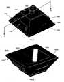
- FIG. 1is a perspective view of an exemplary embodiment of a system 1000, which can comprise a substantially dome-shaped diffuser 1100, which can be formed in the shape of, for example, a truncated 4-sided pyramid, a truncated circular cone, a truncated right circular cone, etc., and can be formed from a optically translucent diffuser material, such as UHMW and/or Teflon.
- a top mount 1200can attach, to diffuser 1100, one or more bright field lights 1250, which can be, for example, Light Emitting Diodes (LED's). When their illumination is diffused by diffuser 1100, bright field lights 1250 can be considered "bright field diffuse lights”.
- LED'sLight Emitting Diodes
- Top mount 1200can define a camera lens hole 1300, through which light can enter a camera lens.
- One or more side portions 1400 of diffuser 1100can include one or more thinned portions 1500, which can provide minimal diffusion of light that passes therethrough.
- Mounted in a thinned portion 1500 on diffuser 1100can be one or more low angle lights 1600, which can be, for example, Light Emitting Diodes (LED's).
- a mount 1700can secure the low angle light 1600 to diffuser 1100.
- the thinned portion 1500can allow for a low angle light 1600 to be non-diffuse while also allowing for the diffuser material to act as a mount for the low angle light 1600, illumination from which can penetrate the diffuser, substantially face an interior zone of the diffuser, and/or diffusely illuminate the interior zone of the diffuser.
- FIG. 2is a perspective view of an exemplary embodiment of a system 2000, which can comprise a substantially dome-shaped diffuser 2100, which can be formed in the shape of, for example, a truncated 4-sided pyramid, a truncated circular cone, a truncated right circular cone, etc., and can be formed from a diffuser material.
- An interior textured surface 2200 of diffuser 2100can be adapted to face an object to be photographed and/or be illuminated by one or more dome lights 2300, which can be, for example, LED's.
- Supporting dome lights 2300can be a dome light mount 2400.
- FIG. 3is a cross-sectional view taken along plane A-A of FIG. 1 of an exemplary embodiment of a system 3000, which can be a "three geometry" lighting system and/or which can comprise a substantially dome-shaped diffuser 1100.
- a top mount 1200which can secure to diffuser 1100 one or more bright field lights 1250, which can be, for example, LED's.
- Mounted co-axially on top mount 1200, through a hole in top mount 1200, and/or within a cavity in top portion 1150can be a lens 3100 that can be attached to a camera.
- Each side portion 1400 of diffuser 1100can include a thinned portion 1500, which can allow for minimal diffusion of low angle lighting.
- Securing one or more low angle lights 1600 to side portion 1400can be a low angle light mount 1700.
- One or more dome lights 1900can be adapted to substantially illuminate at least a portion of a textured interior surface of diffuser 1100.
- Securing one or more dome lights 1900 to diffuser 1100can be a dome light mount 1800. Any of lights 1250, 1600, or 1900 can be used to illuminate an inspected part 3300.
- Arrays of low angle lights 1600 located on opposing side portions 1400 of diffuser 1100can be separated by, for example, approximately 120 degrees as measured from a cross-sectional axis of an inspected part 3300.
- Diffuser 1100can effectively illuminate part 3300 from 3 sides of a substantially hexagonally shaped zone.
- a rule of thumb for using a camera to look at a cylindrical partis to keep the barcode width less than 1/6 th the diameter of the cylinder. For example, for a cylindrical part with a 6 inch diameter, the rule of thumb suggests limiting the width of a Data Matrix marked on the part to approximately 1 inch.
- Top portion 1150 and each of side portions 1400 of diffuser 1100can be dimensioned and/or positioned to correspond to a projection of that Data Matrix.
- system 1000 and/or diffuser 1100can provide illumination at angles sufficient to meet a plurality of lighting requirements for camera-based inspections of cylindrical parts (and/or other shaped parts).
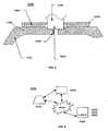
- FIG. 4is a cross-sectional view taken along plane A-A of FIG. 1 of an exemplary embodiment of a system 4000, which can be a "multi-sided geometry" lighting system and/or which can comprise a substantially dome-shaped diffuser 1100.
- a top mount 1200which can secure to diffuser 1100 one or more bright field lights 1250, which can be, for example, LED's.
- Mounted in, above, and/or through a hole in top mount 1200 and/or within a cavity in top portion 1150can be a lens 3100.
- Mounted within a hole in top portion 1150can be an angled two way mirror 3200.
- Each side portion 1400 of diffuser 1100can include a thinned portion 1500, which can allow for minimal diffusion of low angle lighting.
- Securing one or more low angle lights 1600, 1650 to side portion 1400can be a low angle light mount 1700.
- Securing one or more dome lights 1900 to diffuser 1100can be a dome light mount 1800.
- Each of dome lights 1900can be an LED that is directed into a beam-splitter and/or prism 1940, such as for example, a prism having three polished sides.
- An angled side 1920 of prism 1940can horizontally reflect most of the light incident from the LED. A portion of the light incident from the LED can escape from prism 1940 through angled side 1920 as non-diffused light.
- prism 1940can have the angled face 1920 of the prism textured (sandblasted). This texturing can cause the light to be partially directed horizontally and part of the light can escape out as diffused light. This can be useful for handheld barcode readers. In an exemplary implementation where this lighting would be used as an all-in-one solution for a handheld reader, this extra lighting can enable the reader to illuminate very wide barcodes. Any of lights 1250, 1600, 1650, or 1900 can be used to illuminate an inspected part 3300. An inside surface 1120 of any portion of diffuser 1100 can textured.
- a first opposing pair of arrays of low angle lights 1600 located on opposing side portions 1400 of diffuser 1100can be separated by, for example, approximately 90 degrees as measured from a cross-sectional axis of an inspected part 3300.
- a second opposing pair of arrays of low angle lights 1650 located on opposing side portions 1400 of diffuser 1100can be separated by, for example, approximately 120 degrees as measured from a cross-sectional axis of an inspected part 3300.
- Diffuser 1100can effectively illuminate part 3300 from up to 5 or 6 or more directions.
- FIG. 5is a partial cross-sectional view taken along plane A-A of FIG. 1 of an exemplary embodiment of a system 5000, which can comprise a substantially dome-shaped diffuser 1100.
- a top mount 1200To a top portion 1150 of diffuser 1100 can be secured a top mount 1200, which can secure to diffuser 1100 one or more bright field lights 1250, which can be, for example, LED's.
- Light 5400 emitted by bright field lights 1250can be diffused by top portion 1150 of diffuser 1100Mounted through a hole in top mount 1200 and/or within a cavity in top portion 1150 can be a lens 5100 via which, after passing through hole 5200 in diffuser 1100, light and/or photons 5500 corresponding to an image of an inspected part can enter a camera.
- FIG. 6is a block diagram of an exemplary embodiment of a system 6000, which can comprise a diffuser sub-system 6100 the power to various lights of which can be selectively powered and/or controlled by a lighting controller 6200 and/or by an information device 6300 comprising a lighting controller 6320 that can respond to machine instructions 6340 that can be programmed via a user interface 6360.
- Information device 6300can be communicatively coupled to lighting controller 6320 and/or diffuser sub-system 6100 via hard-wiring and/or a network 6400.
- FIG. 7is a block diagram of an exemplary embodiment of an information device 7000, which in certain operative embodiments can comprise, for example, controller 6200 and/or information device 6300 of FIG. 6 .
- Information device 7000can comprise any of numerous components, such as for example, one or more network interfaces 7100, one or more processors 7200, one or more memories 7300 containing instructions 7400, one or more input/output (I/O) devices 7500, and/or one or more user interfaces 7600 coupled to I/O device 7500, etc.
- I/Oinput/output
- a uservia one or more user interfaces 7600, such as a graphical user interface, a user can view a rendering of information related to researching, designing, modeling, creating, developing, building, manufacturing, operating, adjusting, controlling, maintaining, storing, marketing, selling, delivering, selecting, specifying, requesting, ordering, receiving, returning, rating, and/or recommending any of the systems, devices, products, services, methods, and/or information described herein.
- FIG. 8is a flowchart of an exemplary embodiment of a method 8000.
- an object to be inspected, photographed, and/or illuminatedcan be placed and/or positionally adjusted within a substantially domed-shaped diffuser.
- a lighting controllercan be manually or automatically adjusted to cause the object to be diffusely illuminated via a least one selected set of bright field lights mounted on the diffuser.
- a lighting controllercan be manually or automatically adjusted to cause the object to be diffusely illuminated via a least one selected set of low angle lights mounted on a top portion of the diffuser.
- a lighting controllercan be manually or automatically adjusted to cause the object to be reflectively illuminated via a least one selected set of dome lights mounted on a bottom portion of the diffuser.
- the objectcan be inspected, photographed, and/or an image of the object can be captured via light entering a camera via a hole in a top portion of the diffuser and a lens coupled to the camera, the lens positioned in a cavity in and/or supported by the top portion of the diffuser.
- Any of activities 8100-8500can be repeated as desired.
- the cameracan cycle through a series of different lighting techniques and take a picture after each configuration change. The cycle can stop as soon as the desired image is found or it can cycle through some and/or all of the options and pick the best. Grading may happen after each image capture or at the end of all the captures.
- apparatus -an appliance or device for a particular purpose at least - not less than. attach - to fasten, secure, couple, and/or join. automatic - performed via an information device in a manner essentially independent of influence and/or control by a user.
- axial -located on, around, or in the direction of an axis.
- axis -a straight line about which a body or geometric object rotates or can be conceived to rotate and/or a center line to which parts of a structure or body can be referred. based - being derived from.
- beam splitter -a device adapted to split or join a light beam into or from two or more beams that differ in wavelength, polarity, and/or direction.
- beam splitting -a process of splitting or joining a light beam Into or from two or more beams that differ in wavelength, polarity, and/or direction.
- bright field- characterized by illumination at an angle such that light will be reflected into the camera lens.
- camera -a device often comprising a lightproof enclosure having an aperture with a lens through which a still and/or moving image of an object is focused and recorded on a photosensitive film, plate, tape, and/or or sensor coupled to an electronic and/or optical memory device (e.g., RAM, EEPROM, flash memory, magnetic disk, optical disk, etc.) can - is capable of, in at least some embodiments. capture - to obtain and store. cause - to produce an effect. central - situated at, In, or near the center of a length. circular- having a cross-section of a circle. close proximity - within approximately 0.25, 0.5, and/or 1 inches of.
- an electronic and/or optical memory devicee.g., RAM, EEPROM, flash memory, magnetic disk, optical disk, etc.
- central -situated at, In, or near the center of a length.
- circular-having a cross-section of a circle. close proximity - within approximately 0.25, 0.5, and/or 1 inches of.
- co-axial - two or more objectsthat are located on, around, or in the direction of a common axis.
- cone -a solid whose surface Is generated by a line passing through a fixed point and a fixed plane curve not containing the point, consisting of two equal sections joined at a vertex. configure - to make suitable or fit for a specific use or situation.
- controller -a device and/or set of machine-readable Instructions for performing one or more predetermined and/or user-defined tasks.
- a controllercan comprise any one or a combination of hardware, firmware, and/or software.
- a controllercan utilize mechanical, pneumatic, hydraulic, electrical, magnetic, optical, informational, chemical, and/or biological principles, signals, and/or inputs to perform the task(s).
- a controllercan act upon information by manipulating, analyzing, modifying, converting, transmitting the information for use by an executable procedure and/or an information device, and/or routing the information to an output device.
- a controllercan be a central processing unit, a local controller, a remote controller, parallel controllers, and/or distributed controllers, etc.
- the controllercan be a general-purpose microcontroller, such the Pentium IV series of microprocessor manufactured by the Intel Corporation of Santa Clara, California, and/or the HC08 series from Motorola of Schaumburg, Illinois.
- the controllercan be an Application Specific integrated Circuit (ASIC) or a Field Programmable Gate Array (FPGA) that has been designed to implement in its hardware and/or firmware at least a part of an embodiment disclosed herein.
- ASICApplication Specific integrated Circuit
- FPGAField Programmable Gate Array
- data - distinct pieces of informationusually formatted in a special or predetermined way and/or organized to express concepts.
- define -to establish the meaning, relationship, outline, form, and/or structure of; and/or to precisely and/or distinctly describe and/or specify.
- diffuser -a substantially translucent structure adapted to expand the diameter of a light source and/or reduce the effects of focused or collimated lighting.
- direction -a spatial relation between something and a course along which it points and/or moves; a distance independent relationship between two points in space that specifies the position of either with respect to the other; and/or a relationship by which the alignment and/or orientation of any position with respect to any other position is established.
- dome-shaped -having the shape and/or form of a dome and/or a structure having a circular, polygonal, or elliptical base and a very, generally hemispherical or semispherical shape.
- incident - falling or striking on somethinginclude - comprise information device -any device capable of processing data and/or information, such as any general purpose and/or special purpose computer, such as a personal computer, workstation, server, minicomputer, mainframe, supercomputer, computer terminal, laptop, wearable computer, and/or Personal Digital Assistant (PDA), mobile terminal, Bluetooth device, communicator, "smart" phone (such as a Treo-like device), messaging service (e.g., Blackberry) receiver, pager, facsimile, cellular telephone, a traditional telephone, telephonic device, a programmed microprocessor or microcontroller and/or peripheral integrated circuit elements, an ASIC or other integrated circuit, a hardware electronic logic circuit such as a discrete element circuit, and/or a programmable logic device such as a PLD, PLA, FPGA, or PAL, or the like, etc.
- PDAPersonal Digital Assistant
- mobile terminalsuch as a personal computer, workstation, server, minicomputer, mainframe, supercomputer, computer terminal, laptop, wear
- any device on which resides a finite state machine capable of implementing at least a portion of a method, structure, and/or or graphical user interface described hereinmay be used as an information device.
- An information devicecan comprise components such as one or more network interfaces, one or more processors, one or more memories containing instructions, and/or one or more input/output (I/O) devices, one or more user interfaces coupled to an I/O device, etc.
- I/Oinput/output
- I/O deviceany sensory-oriented input and/or output device, such as an audio, visual, haptic, olfactory, and/or taste-oriented device, including, for example, a monitor, display, projector, overhead display, keyboard, keypad, mouse, trackball, joystick, gamepad, wheel, touchpad, touch panel, pointing device, microphone, speaker, video camera, camera, scanner, printer, haptic device, vibrator, tactile simulator, and/or tactile pad, potentially including a port to which an VO device can be attached or connected. inspect-to review. interior - being within; inside of anything; internal; inner; further toward a center. into - to a condition, state, or form of.
- lens -a piece of transparent substance, usually glass, having two opposite surfaces either both curved or one curved and one plane, used in an optical device for changing the convergence and/or focal point of light rays; an optical device with approximate axial symmetry that transmits light, refracts light, and is adapted to cause the light to concentrate and/or diverge.
- LEDlight emitting diode
- LED- a semiconductor device that emits light responsive to an applied electrical conducting current. lighting - an illuminating agent or source. location - a place. longitudinal - of and/or relating to a length; placed and/or running lengthwise.
- ⁇ low angle light -a light that illuminates in such a manner as to cause the light to be reflected away from a camera lens machine - a device and/or vehicle adapted to perform at least one task.
- machine instructions - directionsadapted to cause a machine, such as an information device, to perform one or more particular activities, operations, or functions.
- the directionswhich can sometimes form an entity called a "processor”, “kernel”, “operating system”, “program”, “application”, “utility”, “subroutine”, “script”, “macro”, “file”, “project”, “module”, “library”, “class”, and/or “object”, etc., can be embodied as machine code, source code, object code, compiled code, assembled code, interpretable code, and/or executable code, etc., in hardware, firmware, and/or software.
- machine readable mediuma physical structure from which a machine can obtain data and/or information. Examples include a memory, punch cards, etc. may - is allowed and/or permitted to, in at least some embodiments.
- memory device -an apparatus capable of storing analog or digital information, such as instructions and/or data. Examples include a non-volatile memory, volatile memory, Random Access Memory, RAM, Read Only Memory, ROM, flash memory, magnetic media, a hard disk, a floppy disk, a magnetic tape, an optical media, an optical disk, a compact disk, a CD, a digital versatile disk, a DVD, and/or a raid array, etc.
- the memory devicecan be coupled to a processor and/or can store instructions adapted to be executed by processor, such as according to an embodiment disclosed herein.
- method -a process, procedure, and/or collection of related activities for accomplishing something. minimal - at a lowest level. mirror - a reflecting surface.
- network -a communicatively coupled plurality of nodes.
- a networkcan be and/or utilize any of a wide variety of sub-networks, such as a circuit switched, public-switched, packet switched, data, telephone, telecommunications, video distribution, cable, terrestrial, broadcast, satellite, broadband, corporate, global, national, regional, wide area, backbone, packet-switched TCP/IP, Fast Ethernet, Token Ring, public internet, private, ATM, multi-domain, and/or multi-zone sub-network, one or more internet service providers, and/or one or more information devices, such as a switch, router, and/or gateway not directly connected to a local area network, etc.
- sub-networkssuch as a circuit switched, public-switched, packet switched, data, telephone, telecommunications, video distribution, cable, terrestrial, broadcast, satellite, broadband, corporate, global, national, regional, wide area, backbone, packet-switched TCP/IP, Fast Ethernet, Token Ring, public internet, private, ATM, multi-domain
- a network interfaceany device, system, or subsystem capable of coupling an information device to a network.
- a network interfacecan be a telephone, cellular phone, cellular modem, telephone data modem, fax modem, wireless transceiver, ethernet card, cable modem, digital subscriber line interface, bridge, hub, router, or other similar device.
- pluralitythe state of being plural and/or more than one.
- portion -a part, component, section, percentage, ratio, and/or quantity that is less than a larger whole. Can be visually, physically, and/or virtually distinguishable and/or non-distinguishable.
- processor -a device and/or set of machine-readable instructions for performing one or more predetermined tasks.
- a processorcan comprise any one or a combination of hardware, firmware, and/or software.
- a processorcan utilize mechanical, pneumatic, hydraulic, electrical, magnetic, optical, informational, chemical, and/or biological principles, signals, and/or inputs to perform the task(s).
- a processorcan act upon information by manipulating, analyzing, modifying, converting, transmitting the information for use by an executable procedure and/or an information device, and/or routing the information to an output device.
- a processorcan function as a central processing unit, local controller, remote controller, parallel controller, and/or distributed controller, etc.
- the processorcan be a general-purpose device, such as a microcontroller and/or a microprocessor, such the Pentium IV series of microprocessor manufactured by the Intel Corporation of Santa Clara, California.
- the processorcan be dedicated purpose device, such as an Application Specific Integrated Circuit (ASIC) or a Field Programmable Gate Array (FPGA) that has been designed to implement in its hardware and/or firmware at least a part of an embodiment disclosed herein.
- ASICApplication Specific Integrated Circuit
- FPGAField Programmable Gate Array
- pyramid -a solid having a polygonal base and triangular sides that meet in a point. reach - to arrive at. receive - to gather, take, acquire, obtain, accept, get, and/or have bestowed upon. reflect - to cast back incident light from a surface.
- region -a continuous part of a surface. render-to make perceptible to a human, for example as data, commands, text, graphics, audio, video, animation, and/or hyperlinks, etc., such as via any visual, audio, and/or haptic means, such as via a display, monitor, electric paper, ocular implant, cochlear implant, speaker, etc. repeatedly - again and again; repetitively. requirement-a demand, need, and/or request...
- response -a reaction to an influence and/or impetus.
- said -when used In a system or device claim, an article indicating a subsequent claim term that has been previously introduced.
- second - immediately following an initial item in an ordering.select - to make a choice or selection from alternatives. selectively - via choice.
- shape -a characteristic surface, outline, and/or contour of an entity.
- side -a surface bounding a solid object.
- signal - informationsuch as machine instructions for activities, encoded as automatically detectable variations in a physical variable, such as a pneumatic, hydraulic, acoustic, fluidic, mechanical, electrical, magnetic, optical, chemical, and/or biological variable, such as power, energy, pressure, flowrate, viscosity, density, torque, impact, force, voltage, current, resistance, magnetomotive force, magnetic field intensity, magnetic field flux, magnetic flux density, reluctance, permeability, index of refraction, optical wavelength, polarization, reflectance, transmittance, phase shift, concentration, and/or temperature, etc.
- a physical variablesuch as a pneumatic, hydraulic, acoustic, fluidic, mechanical, electrical, magnetic, optical, chemical, and/or biological variable, such as power, energy, pressure, flowrate, viscosity, density, torque, impact, force, voltage, current, resistance, magnetomotive force, magnetic field intensity, magnetic field flux, magnetic flux density, reluctance, permeability, index of refraction, optical wavelength
- a signalcan be synchronous, asychronous, hard real-time, soft real-time, non-real time, continuously generated, continuously varying, analog, discretely generated, discretely varying, quantized, digital, continuously measured, and/or discretely measured, etc.
- source -an original transmitter and/or a point at which something originates, springs into being, and/or from which it derives and/or is obtained.
- systema collection of mechanisms, devices, data, and/or instructions, the collection designed to perform one or more specific functions.
- user interfaceany device for rendering information to a user and/or requesting information from the user.
- a user interfaceincludes at least one of textual, graphical, audio, video, animation, and/or haptic elements.
- a textual elementcan be provided, for example, by a printer, monitor, display, projector, etc.
- a graphical elementcan be provided, for example, via a monitor, display, projector, and/or visual indication device, such as a light, flag, beacon, etc.
- An audio elementcan be provided, for example, via a speaker, microphone, and/or other sound generating and/or receiving device.
- a video element or animation elementcan be provided, for example, via a monitor, dlsplay, projector, and/or other visual device.
- a haptic elementcan be provided, for example, via a very low frequency speaker, vibrator, tactile stimulator, tactile pad, simulator, keyboard, keypad, mouse, trackball, joystick, gamepad, wheel, touchpad, touch panel, pointing device, and/or other haptic device, etc.
- a user interfacecan include one or more textual elements such as, for example, one or more letters, number, symbols, etc.
- a user interfacecan include one or more graphical elements such as, for example, an image, photograph, drawing, icon, window, title bar, panel, sheet, tab, drawer, matrix, table, form, calendar, outline view, frame, dialog box, static text, text box, list, pick list, pop-up list, pull-down list, menu, tool bar, dock, check box, radio button, hyperlink, browser, button, control, palette, preview panel, color wheel, dial, slider, scroll bar, cursor, status bar, stepper, and/or progress indicator, etc.
- a textual and/or graphical elementcan be used for selecting, programming, adjusting, changing, specifying, etc.
- a user Interfacecan include one or more audio elements such as, for example, a volume control, pitch control, speed control, voice selector, and/or one or more elements for controlling audio play, speed, pause, fast forward, reverse, etc.
- a user interfacecan include one or more video elements such as, for example, elements controlling video play, speed, pause, fast forward, reverse, zoom-in, zoom-out, rotate, and/or tilt, etc.
- a user interfacecan include one or more animation elements such as, for example, elements controlling animation play, pause, fast forward, reverse, zoom-in, zoom-out, rotate, tilt, color, intensity, speed, frequency, appearance, etc.
- a user interfacecan include one or more haptic elements such as, for example, elements utilizing tactile stimulus, force, pressure, vibration, motion, displacement, temperature, etc. via - by way of and/or utilizing. wall - a partition, structure, and/or mass that serves to enclose, divide, separate, segregate, define, and/or protect a volume and/or to support a floor, ceiling, and/or another wall. wherein - in regard to which; and; and/or in addition to. within - inside. zone - and volume and/or region.
Landscapes
- Physics & Mathematics (AREA)
- Electromagnetism (AREA)
- General Physics & Mathematics (AREA)
- Engineering & Computer Science (AREA)
- Health & Medical Sciences (AREA)
- General Health & Medical Sciences (AREA)
- Theoretical Computer Science (AREA)
- Computer Vision & Pattern Recognition (AREA)
- Artificial Intelligence (AREA)
- Toxicology (AREA)
- Chemical & Material Sciences (AREA)
- Pathology (AREA)
- Immunology (AREA)
- Biochemistry (AREA)
- Analytical Chemistry (AREA)
- Life Sciences & Earth Sciences (AREA)
- Non-Portable Lighting Devices Or Systems Thereof (AREA)
- Investigating Materials By The Use Of Optical Means Adapted For Particular Applications (AREA)
- Instruments For Viewing The Inside Of Hollow Bodies (AREA)
Description
- Camera-based inspections often require lighting to be optimized for a given application. Optimized lighting for an application can become difficult when parts vary in geometry and/or finnish.
- Direct Part Marking (DPM) is a technology whereby an item is physically altered by methods such as dot peening, laser etching, molding, and/or embossing to produce two different surface conditions.
- Marking can result in the symbol being created by either smooth and rough (or dull and shiny) areas on the substrate or a symbol comprised "dots" below or above the substrate surface. DPM is typically used with matrix symbologies.
- As a result, there is often very little or no contrast between the "marked" elements of a symbol and the background (substrate). Contrast can be achieved by using specific types of lighting and signal processing techniques.
- A Data Matrix is a type of barcode that relies on print quality grading systems to ensure that the codes are printed well and will be readable in the future. The Association for Automatic Identification and Mobility (AIM) maintains a specification for Data Matrix verification, which is a process of determining the print quality of, for example, a "barcode'" a symbol created by Direct Part Marking, etc. Using the traditional barcode as an example, let's say that you were printing the barcode and the toner on your printer was running low, such that you have a section where the barcode is faded and/or missing some of the bars. You also might have an overzealous courier who makes a black line with a marker through the barcode. These types of damage to the code can make it difficult or impossible to read the barcode. The same principle exists for 3D barcodes. For example, if a laser is marking a fuel injector and the beam passes over a drop of oil, it might not mark the part in that section. The specification mentioned above has a series of tests for issues such as missing parts of the code, faded codes, and angular distorted codes. If you were to put a mark on a mirror surface or a flat black cylinder, if you do not utilize the right light, you might not even see the mark. The following text is the summary of the AIM specification's currently required lighting:
- Two lighting environments each with sub-options are defined in this document. The lighting environments are denoted in the reported grade using the format defined in ISO/IEC 15415, section 6.2, using the angle specifier with a combination of numbers and letters as defined below.
- Note: This does not limit the prerogative of an Application Specification to choose different lighting environments based on application requirements. Alternate lighting environments should include specifiers consistent with the format of those below that can be used for communicating quality requirements and quality grades.
- A flat diffusing material is oriented such that the plane of the material is parallel to the plane of the sensor. The symbol is uniformly illuminated with diffuse light incident at 90 degrees to the plane of the symbol. The angle specifier shall be 90.
- A diffusely reflecting dome is illuminated from below so that the reflected light falls non-directionally on the part and does not cast defined shadows. This is commonly used for reading curved parts. The angle specifier shall be D.
- Two orthogonal lighting planes are defined such that both planes are perpendicular to the surface of the image sensor and one plane is parallel to the line formed by a horizontal edge of the image sensor to within +/- 5 degrees. Light is directionally aimed at the part such that the line formed by the center of the light source and center of the symbol rests in one of the lighting planes and is at an angle of 30 +/- 3 degrees from the horizontal plane of the surface of the symbol. The lighting shall illuminate the entire symbol area with uniform energy.
- Light is aimed at the part from four sides. The angle specifier shall be 30Q.
- Light is aimed at the part from two sides in one of the two lighting planes. The angle specifier shall be 30T.
- Light is aimed at the part from any one of the four sides. The angle specifier shall be 30S.
- Thus, conventional technology can require a user to manually change the lighting used for each of a number of different verification methods.
- Patent document
US-5684530-A discloses a method and apparatus for providing an elongate linear continuous, uniformed, diffused lighting environment for use with documents with shiny surfaces. - Patent document
EP-1688861-A2 discloses a reader with an integrated light emitting diode (LED) to illuminate a reading area. - Patent document
WO-2005/043449-A1 discloses a system and method for selectively controlling the illumination, and particularly dark field illumination, applied to a symbol to be decoded, and for determining a suitable or optimized level of lighting for decoding the symbol. - Combining a number of different lighting techniques into one single system to enable the user and/or a user program to cycle through the options until the optimal lighting is selected can be desirable. There can be a substantial utility for a system that provides all of the options required by a specification such as that described supra by AIM (and/or other options for non-Data Matrix Verification applications) without a user having to manually change from one given light to another.
- Certain exemplary embodiments can provide a system comprising: a diffuser defining a camera lens hole in a top portion of said diffuser, said diffuser adapted to receive at least one set of low angle lights; and a plurality of lights mounted on said diffuser in proximity to said camera lens hole.
- Certain exemplary embodiments can enable the utilization of any of many different lighting techniques via a single system, which can be helpful for camera-based inspections, such as for machine vision applications such as Data Matrix Verification.
- A wide variety of potential practical and useful embodiments will be more readily understood through the following detailed description of certain exemplary embodiments, with reference to the accompanying exemplary drawings in which:
FIG. 1 is a perspective view of an exemplary embodiment of asystem 1000;FIG. 2 is a perspective view of an exemplary embodiment of asystem 2000;FIG. 3 is a cross-sectional view taken along planeA-A ofFIG. 1 of an exemplary embodiment of asystem 3000;FIG. 4 is a cross-sectional view taken along planeA-A ofFIG. 1 of an exemplary embodiment of asystem 4000;FIG. 5 is a partial cross-sectional view taken along planeA-A ofFIG. 1 of an exemplary embodiment of asystem 5000;FIG. 6 is a block diagram of an exemplary embodiment of asystem 6000;FIG. 7 is a block diagram of an exemplary embodiment of aninformation device 7000; andFIG. 8 is a flowchart of an exemplary embodiment of amethod 8000.- The lighting system of certain exemplary embodiments can independently, programmatically, and/or automatically control any of at least 4 low angle lights. Continuously Diffuse Illumination (CDI) uniformity on the top of the dome can be improved by using illumination from a bright field illumination source, such as LED's. In certain exemplary embodiments, the bright field LEDs can be set to a lower intensity. The low angle lights could be controlled to illuminate one light at a time (e.g., N,S,E,or W), two at a time (e.g., N-S,E-W), and/or all four at a time. The CDI lighting can be only created by the reflection of the upward facing LEDs or could be created by backlighting the translucent dome.
- The automatic lighting system of certain exemplary embodiments can be applied to determine compliance with various specifications of the AIM's Technical Symbology Committee and/or to non-Data Matrix machine vision applications.
- The AIM TSC lighting combinations can include any of:
- Dome lighting
- Bright Field Diffuse lighting
- Low angle non-diffuse from the North location
- Low angle non-diffuse from the South location
- Low angle non-diffuse from the East location
- Low angle non-diffuse from the West location
- Low angle non-diffuse from the North-South locations
- Low angle non-diffuse from the East-West locations
- Low angle non-diffuse from the North-South-East-West locations
- Certain exemplary embodiments can fulfill at least the AIM TSC lighting requirements.
- Certain exemplary embodiments can provide a method of creating a CDI effect. CDI as described above also has the nickname of "Cloudy Day Illumination", where the "effect" is little or no shadows. To facilitate this effect, certain exemplary embodiments can interpose a diffusion material and/or diffuser between a source of bright field, low angle, and/or indirect, dome lighting elements and the part to be illuminated.
FIG. 1 is a perspective view of an exemplary embodiment of asystem 1000, which can comprise a substantially dome-shapeddiffuser 1100, which can be formed in the shape of, for example, a truncated 4-sided pyramid, a truncated circular cone, a truncated right circular cone, etc., and can be formed from a optically translucent diffuser material, such as UHMW and/or Teflon. Atop mount 1200 can attach, todiffuser 1100, one or morebright field lights 1250, which can be, for example, Light Emitting Diodes (LED's). When their illumination is diffused bydiffuser 1100,bright field lights 1250 can be considered "bright field diffuse lights".Top mount 1200 can define acamera lens hole 1300, through which light can enter a camera lens. One ormore side portions 1400 ofdiffuser 1100 can include one or more thinnedportions 1500, which can provide minimal diffusion of light that passes therethrough. Mounted in a thinnedportion 1500 ondiffuser 1100 can be one or morelow angle lights 1600, which can be, for example, Light Emitting Diodes (LED's). Amount 1700 can secure the low angle light 1600 todiffuser 1100. The thinnedportion 1500 can allow for a low angle light 1600 to be non-diffuse while also allowing for the diffuser material to act as a mount for the low angle light 1600, illumination from which can penetrate the diffuser, substantially face an interior zone of the diffuser, and/or diffusely illuminate the interior zone of the diffuser.FIG. 2 is a perspective view of an exemplary embodiment of asystem 2000, which can comprise a substantially dome-shapeddiffuser 2100, which can be formed in the shape of, for example, a truncated 4-sided pyramid, a truncated circular cone, a truncated right circular cone, etc., and can be formed from a diffuser material. An interiortextured surface 2200 ofdiffuser 2100 can be adapted to face an object to be photographed and/or be illuminated by one ormore dome lights 2300, which can be, for example, LED's. Supportingdome lights 2300 can be adome light mount 2400.FIG. 3 is a cross-sectional view taken along planeA-A ofFIG. 1 of an exemplary embodiment of asystem 3000, which can be a "three geometry" lighting system and/or which can comprise a substantially dome-shapeddiffuser 1100. To atop portion 1150 ofdiffuser 1100 can be secured atop mount 1200, which can secure todiffuser 1100 one or morebright field lights 1250, which can be, for example, LED's. Mounted co-axially ontop mount 1200, through a hole intop mount 1200, and/or within a cavity intop portion 1150 can be alens 3100 that can be attached to a camera.- Each
side portion 1400 ofdiffuser 1100 can include a thinnedportion 1500, which can allow for minimal diffusion of low angle lighting. Securing one or morelow angle lights 1600 toside portion 1400 can be a lowangle light mount 1700. One ormore dome lights 1900 can be adapted to substantially illuminate at least a portion of a textured interior surface ofdiffuser 1100. Securing one ormore dome lights 1900 todiffuser 1100 can be adome light mount 1800. Any oflights part 3300. - Arrays of
low angle lights 1600 located on opposingside portions 1400 ofdiffuser 1100 can be separated by, for example, approximately 120 degrees as measured from a cross-sectional axis of an inspectedpart 3300.Diffuser 1100 can effectively illuminatepart 3300 from 3 sides of a substantially hexagonally shaped zone. A rule of thumb for using a camera to look at a cylindrical part is to keep the barcode width less than 1/6th the diameter of the cylinder. For example, for a cylindrical part with a 6 inch diameter, the rule of thumb suggests limiting the width of a Data Matrix marked on the part to approximately 1 inch.Top portion 1150 and each ofside portions 1400 ofdiffuser 1100 can be dimensioned and/or positioned to correspond to a projection of that Data Matrix. Thus,system 1000 and/ordiffuser 1100 can provide illumination at angles sufficient to meet a plurality of lighting requirements for camera-based inspections of cylindrical parts (and/or other shaped parts). FIG. 4 is a cross-sectional view taken along planeA-A ofFIG. 1 of an exemplary embodiment of asystem 4000, which can be a "multi-sided geometry" lighting system and/or which can comprise a substantially dome-shapeddiffuser 1100. To atop portion 1150 ofdiffuser 1100 can be secured atop mount 1200, which can secure todiffuser 1100 one or morebright field lights 1250, which can be, for example, LED's. Mounted in, above, and/or through a hole intop mount 1200 and/or within a cavity intop portion 1150 can be alens 3100. Mounted within a hole intop portion 1150 can be an angled two way mirror 3200.- Each
side portion 1400 ofdiffuser 1100 can include a thinnedportion 1500, which can allow for minimal diffusion of low angle lighting. Securing one or morelow angle lights side portion 1400 can be a lowangle light mount 1700. Securing one ormore dome lights 1900 todiffuser 1100 can be adome light mount 1800. Each ofdome lights 1900 can be an LED that is directed into a beam-splitter and/orprism 1940, such as for example, a prism having three polished sides. Anangled side 1920 ofprism 1940 can horizontally reflect most of the light incident from the LED. A portion of the light incident from the LED can escape fromprism 1940 through angledside 1920 as non-diffused light. Another potential type ofprism 1940 can have the angledface 1920 of the prism textured (sandblasted). This texturing can cause the light to be partially directed horizontally and part of the light can escape out as diffused light. This can be useful for handheld barcode readers. In an exemplary implementation where this lighting would be used as an all-in-one solution for a handheld reader, this extra lighting can enable the reader to illuminate very wide barcodes. Any oflights part 3300. Aninside surface 1120 of any portion ofdiffuser 1100 can textured. - A first opposing pair of arrays of
low angle lights 1600 located on opposingside portions 1400 ofdiffuser 1100 can be separated by, for example, approximately 90 degrees as measured from a cross-sectional axis of an inspectedpart 3300. A second opposing pair of arrays oflow angle lights 1650 located on opposingside portions 1400 ofdiffuser 1100 can be separated by, for example, approximately 120 degrees as measured from a cross-sectional axis of an inspectedpart 3300.Diffuser 1100 can effectively illuminatepart 3300 from up to 5 or 6 or more directions. FIG. 5 is a partial cross-sectional view taken along planeA-A ofFIG. 1 of an exemplary embodiment of asystem 5000, which can comprise a substantially dome-shapeddiffuser 1100. To atop portion 1150 ofdiffuser 1100 can be secured atop mount 1200, which can secure todiffuser 1100 one or morebright field lights 1250, which can be, for example, LED's. Light 5400 emitted bybright field lights 1250 can be diffused bytop portion 1150 of diffuser 1100Mounted through a hole intop mount 1200 and/or within a cavity intop portion 1150 can be alens 5100 via which, after passing throughhole 5200 indiffuser 1100, light and/orphotons 5500 corresponding to an image of an inspected part can enter a camera.FIG. 6 is a block diagram of an exemplary embodiment of asystem 6000, which can comprise adiffuser sub-system 6100 the power to various lights of which can be selectively powered and/or controlled by alighting controller 6200 and/or by aninformation device 6300 comprising alighting controller 6320 that can respond tomachine instructions 6340 that can be programmed via auser interface 6360.Information device 6300 can be communicatively coupled tolighting controller 6320 and/ordiffuser sub-system 6100 via hard-wiring and/or anetwork 6400.FIG. 7 is a block diagram of an exemplary embodiment of aninformation device 7000, which in certain operative embodiments can comprise, for example,controller 6200 and/orinformation device 6300 ofFIG. 6 .Information device 7000 can comprise any of numerous components, such as for example, one ormore network interfaces 7100, one ormore processors 7200, one ormore memories 7300 containinginstructions 7400, one or more input/output (I/O)devices 7500, and/or one ormore user interfaces 7600 coupled to I/O device 7500, etc.- In certain exemplary embodiments, via one or
more user interfaces 7600, such as a graphical user interface, a user can view a rendering of information related to researching, designing, modeling, creating, developing, building, manufacturing, operating, adjusting, controlling, maintaining, storing, marketing, selling, delivering, selecting, specifying, requesting, ordering, receiving, returning, rating, and/or recommending any of the systems, devices, products, services, methods, and/or information described herein. FIG. 8 is a flowchart of an exemplary embodiment of amethod 8000. Atactivity 8100, an object to be inspected, photographed, and/or illuminated can be placed and/or positionally adjusted within a substantially domed-shaped diffuser. Atactivity 8200, a lighting controller can be manually or automatically adjusted to cause the object to be diffusely illuminated via a least one selected set of bright field lights mounted on the diffuser. Atactivity 8300, a lighting controller can be manually or automatically adjusted to cause the object to be diffusely illuminated via a least one selected set of low angle lights mounted on a top portion of the diffuser. Atactivity 8400, a lighting controller can be manually or automatically adjusted to cause the object to be reflectively illuminated via a least one selected set of dome lights mounted on a bottom portion of the diffuser. Atactivity 8500, the object can be inspected, photographed, and/or an image of the object can be captured via light entering a camera via a hole in a top portion of the diffuser and a lens coupled to the camera, the lens positioned in a cavity in and/or supported by the top portion of the diffuser. Any of activities 8100-8500 can be repeated as desired. For example, the camera can cycle through a series of different lighting techniques and take a picture after each configuration change. The cycle can stop as soon as the desired image is found or it can cycle through some and/or all of the options and pick the best. Grading may happen after each image capture or at the end of all the captures.- When the following terms are used substantively herein, the accompanying definitions apply. These terms and definitions are presented without prejudice, and, consistent with the application, the right to redefine these terms during the prosecution of this application or any application claiming priority hereto is reserved. For the purpose of interpreting a claim of any patent that claims priority hereto, each definition (or redefined term if an original definition was amended during the prosecution of that patent), functions as a clear and unambiguous disavowal of the subject matter outside of that definition.
a - at least one.
activity - an action, act, deed, function, step, and/or process and/or a portion thereof.
adapted - suitable, fit, and/or capable of performing a specified function.
adjacent - in close proximity to, near, next to, close, or contiguous; adjoining; neighboring
allow - to provide, let do, happen, and/or permit.
and/or - either in conjunction with or in alternative to.
angled - slanted with respect to an adjacent object and/or reference plane.
apparatus - an appliance or device for a particular purpose
at least - not less than.
attach - to fasten, secure, couple, and/or join.
automatic - performed via an information device in a manner essentially independent of influence and/or control by a user.
axial - located on, around, or in the direction of an axis.
axis - a straight line about which a body or geometric object rotates or can be conceived to rotate and/or a center line to which parts of a structure or body can be referred.
based - being derived from.
beam splitter - a device adapted to split or join a light beam into or from two or more beams that differ in wavelength, polarity, and/or direction.
beam splitting - a process of splitting or joining a light beam Into or from two or more beams that differ in wavelength, polarity, and/or direction.
bright field - characterized by illumination at an angle such that light will be reflected into the camera lens.
camera - a device often comprising a lightproof enclosure having an aperture with a lens through which a still and/or moving image of an object is focused and recorded on a photosensitive film, plate, tape, and/or or sensor coupled to an electronic and/or optical memory device (e.g., RAM, EEPROM, flash memory, magnetic disk, optical disk, etc.)
can - is capable of, in at least some embodiments.
capture - to obtain and store.
cause - to produce an effect.
central - situated at, In, or near the center of a length.
circular- having a cross-section of a circle.
close proximity - within approximately 0.25, 0.5, and/or 1 inches of.
co-axial - two or more objects that are located on, around, or in the direction of a common axis.
comprised - included in; a part of.
comprises - includes, but is not limited to, what follows.
comprising - including but not limited to, what follows.
cone - a solid whose surface Is generated by a line passing through a fixed point and a fixed plane curve not containing the point, consisting of two equal sections joined at a vertex.
configure - to make suitable or fit for a specific use or situation.
controller - a device and/or set of machine-readable Instructions for performing one or more predetermined and/or user-defined tasks. A controller can comprise any one or a combination of hardware, firmware, and/or software. A controller can utilize mechanical, pneumatic, hydraulic, electrical, magnetic, optical, informational, chemical, and/or biological principles, signals, and/or inputs to perform the task(s). In certain embodiments, a controller can act upon information by manipulating, analyzing, modifying, converting, transmitting the information for use by an executable procedure and/or an information device, and/or routing the information to an output device. A controller can be a central processing unit, a local controller, a remote controller, parallel controllers, and/or distributed controllers, etc. The controller can be a general-purpose microcontroller, such the Pentium IV series of microprocessor manufactured by the Intel Corporation of Santa Clara, California, and/or the HC08 series from Motorola of Schaumburg, Illinois. In another embodiment, the controller can be an Application Specific integrated Circuit (ASIC) or a Field Programmable Gate Array (FPGA) that has been designed to implement in its hardware and/or firmware at least a part of an embodiment disclosed herein.
couple - to join, connect, and/or link two things together.
cylindrical - of, relating to, and/or having the shape of a cylinder, especially of a circular cylinder.
data - distinct pieces of information, usually formatted in a special or predetermined way and/or organized to express concepts.
define - to establish the meaning, relationship, outline, form, and/or structure of; and/or to precisely and/or distinctly describe and/or specify.
determine - to obtain, calculate, decide, deduce, and/or ascertain.
device - a machine, manufacture, and/or collection thereof.
diffuse - to spread or scatter.
diffuser - a substantially translucent structure adapted to expand the diameter of a light source and/or reduce the effects of focused or collimated lighting.
direction - a spatial relation between something and a course along which it points and/or moves; a distance independent relationship between two points in space that specifies the position of either with respect to the other; and/or a relationship by which the alignment and/or orientation of any position with respect to any other position is established.
dome-shaped - having the shape and/or form of a dome and/or a structure having a circular, polygonal, or elliptical base and a very, generally hemispherical or semispherical shape.
each - every one of a group considered Individually.
enable - to render capable for a task.
end - an extremity and its vicinity of something that has length: a terminus.
extending - located, placed, and/or stretched lengthwise.
face - the most significant or prominent surface of an object.
formed - constructed.
from - used to indicate a source.
further - in addition.
generate - to create, produce, give rise to, and/or bring into existence.
hole - a hollowed place in an object.
Illuminate - to light and/or cause light to be incident thereon.
image - an at least two-dimensional representation of an entity and/or phenomenon. Multiple images can be presented in a predetermined and timed sequence to recreate and/or produce an appearance of movement.
incident - falling or striking on something
include - comprise
information device -any device capable of processing data and/or information, such as any general purpose and/or special purpose computer, such as a personal computer, workstation, server, minicomputer, mainframe, supercomputer, computer terminal, laptop, wearable computer, and/or Personal Digital Assistant (PDA), mobile terminal, Bluetooth device, communicator, "smart" phone (such as a Treo-like device), messaging service (e.g., Blackberry) receiver, pager, facsimile, cellular telephone, a traditional telephone, telephonic device, a programmed microprocessor or microcontroller and/or peripheral integrated circuit elements, an ASIC or other integrated circuit, a hardware electronic logic circuit such as a discrete element circuit, and/or a programmable logic device such as a PLD, PLA, FPGA, or PAL, or the like, etc. In general any device on which resides a finite state machine capable of implementing at least a portion of a method, structure, and/or or graphical user interface described herein may be used as an information device. An information device can comprise components such as one or more network interfaces, one or more processors, one or more memories containing instructions, and/or one or more input/output (I/O) devices, one or more user interfaces coupled to an I/O device, etc.
input/output (I/O) device - any sensory-oriented input and/or output device, such as an audio, visual, haptic, olfactory, and/or taste-oriented device, including, for example, a monitor, display, projector, overhead display, keyboard, keypad, mouse, trackball, joystick, gamepad, wheel, touchpad, touch panel, pointing device, microphone, speaker, video camera, camera, scanner, printer, haptic device, vibrator, tactile simulator, and/or tactile pad, potentially including a port to which an VO device can be attached or connected.
inspect-to review.
interior - being within; inside of anything; internal; inner; further toward a center.
into - to a condition, state, or form of.
lens - a piece of transparent substance, usually glass, having two opposite surfaces either both curved or one curved and one plane, used in an optical device for changing the convergence and/or focal point of light rays; an optical device with approximate axial symmetry that transmits light, refracts light, and is adapted to cause the light to concentrate and/or diverge.
light-electromagnetic radiation of any wavelength.
light emitting diode (LED) - a semiconductor device that emits light responsive to an applied electrical conducting current.
lighting - an illuminating agent or source.
location - a place.
longitudinal - of and/or relating to a length; placed and/or running lengthwise. \
low angle light - a light that illuminates in such a manner as to cause the light to be reflected away from a camera lens
machine - a device and/or vehicle adapted to perform at least one task.
machine instructions - directions adapted to cause a machine, such as an information device, to perform one or more particular activities, operations, or functions. The directions, which can sometimes form an entity called a "processor", "kernel", "operating system", "program", "application", "utility", "subroutine", "script", "macro", "file", "project", "module", "library", "class", and/or "object", etc., can be embodied as machine code, source code, object code, compiled code, assembled code, interpretable code, and/or executable code, etc., in hardware, firmware, and/or software.
machine readable medium - a physical structure from which a machine can obtain data and/or information. Examples include a memory, punch cards, etc.
may - is allowed and/or permitted to, in at least some embodiments.
memory device - an apparatus capable of storing analog or digital information, such as instructions and/or data. Examples include a non-volatile memory, volatile memory, Random Access Memory, RAM, Read Only Memory, ROM, flash memory, magnetic media, a hard disk, a floppy disk, a magnetic tape, an optical media, an optical disk, a compact disk, a CD, a digital versatile disk, a DVD, and/or a raid array, etc. The memory device can be coupled to a processor and/or can store instructions adapted to be executed by processor, such as according to an embodiment disclosed herein.
method - a process, procedure, and/or collection of related activities for accomplishing something.
minimal - at a lowest level.
mirror - a reflecting surface.
mount - (n) that upon which a thing Is attached, (v) to couple, fix, and/or attach on and/or to something.
network - a communicatively coupled plurality of nodes. A network can be and/or utilize any of a wide variety of sub-networks, such as a circuit switched, public-switched, packet switched, data, telephone, telecommunications, video distribution, cable, terrestrial, broadcast, satellite, broadband, corporate, global, national, regional, wide area, backbone, packet-switched TCP/IP, Fast Ethernet, Token Ring, public internet, private, ATM, multi-domain, and/or multi-zone sub-network, one or more internet service providers, and/or one or more information devices, such as a switch, router, and/or gateway not directly connected to a local area network, etc.
network interface - any device, system, or subsystem capable of coupling an information device to a network. For example, a network interface can be a telephone, cellular phone, cellular modem, telephone data modem, fax modem, wireless transceiver, ethernet card, cable modem, digital subscriber line interface, bridge, hub, router, or other similar device.
non - not.
object - a physical thing.
outer - farther than another from the center and/or middle.
parallel - of, relating to, or designating lines, curves, planes, and/or or surfaces everywhere equidistant and/or an arrangement of components in an electrical circuit that splits an electrical current into two or more paths.
perpendicular- intersecting at or forming substantially right angles; and/or substantially at a right angle with respect to an axis.
plurality - the state of being plural and/or more than one.
portion - a part, component, section, percentage, ratio, and/or quantity that is less than a larger whole. Can be visually, physically, and/or virtually distinguishable and/or non-distinguishable.
position -to put In place or position.
power - energy, a measure of energy and/or work, and/or a rate at which work is done, expressed as the amount of work per unit time and commonly measured in units such as watt and horsepower.
predefined - specified, determined, and/or established in advance.
predetermined - established in advance.
processor - a device and/or set of machine-readable instructions for performing one or more predetermined tasks. A processor can comprise any one or a combination of hardware, firmware, and/or software. A processor can utilize mechanical, pneumatic, hydraulic, electrical, magnetic, optical, informational, chemical, and/or biological principles, signals, and/or inputs to perform the task(s). In certain embodiments, a processor can act upon information by manipulating, analyzing, modifying, converting, transmitting the information for use by an executable procedure and/or an information device, and/or routing the information to an output device. A processor can function as a central processing unit, local controller, remote controller, parallel controller, and/or distributed controller, etc. Unless stated otherwise, the processor can be a general-purpose device, such as a microcontroller and/or a microprocessor, such the Pentium IV series of microprocessor manufactured by the Intel Corporation of Santa Clara, California. In certain embodiments, the processor can be dedicated purpose device, such as an Application Specific Integrated Circuit (ASIC) or a Field Programmable Gate Array (FPGA) that has been designed to implement in its hardware and/or firmware at least a part of an embodiment disclosed herein.
provide - to furnish, supply, give, convey, send, and/or make available.
proximity-the state, quality, sense, and/or fact of being near and/or next; the closeness of one thing to another.
pyramid - a solid having a polygonal base and triangular sides that meet in a point.
reach - to arrive at.
receive - to gather, take, acquire, obtain, accept, get, and/or have bestowed upon.
reflect - to cast back incident light from a surface.
region - a continuous part of a surface.
render-to make perceptible to a human, for example as data, commands, text, graphics, audio, video, animation, and/or hyperlinks, etc., such as via any visual, audio, and/or haptic means, such as via a display, monitor, electric paper, ocular implant, cochlear implant, speaker, etc.
repeatedly - again and again; repetitively.
requirement-a demand, need, and/or request...
response - a reaction to an influence and/or impetus.
said - when used In a system or device claim, an article indicating a subsequent claim term that has been previously introduced.
second - immediately following an initial item in an ordering.
select - to make a choice or selection from alternatives.
selectively - via choice.
set - a related plurality of predetermined elements; and/or one or more distinct items and/or entities having a specific common property or properties.
shape - a characteristic surface, outline, and/or contour of an entity.
side - a surface bounding a solid object.
signal - information, such as machine instructions for activities, encoded as automatically detectable variations in a physical variable, such as a pneumatic, hydraulic, acoustic, fluidic, mechanical, electrical, magnetic, optical, chemical, and/or biological variable, such as power, energy, pressure, flowrate, viscosity, density, torque, impact, force, voltage, current, resistance, magnetomotive force, magnetic field intensity, magnetic field flux, magnetic flux density, reluctance, permeability, index of refraction, optical wavelength, polarization, reflectance, transmittance, phase shift, concentration, and/or temperature, etc. Depending on the context, a signal can be synchronous, asychronous, hard real-time, soft real-time, non-real time, continuously generated, continuously varying, analog, discretely generated, discretely varying, quantized, digital, continuously measured, and/or discretely measured, etc.
source - an original transmitter and/or a point at which something originates, springs into being, and/or from which it derives and/or is obtained.
store - to place, hold, and/or retain data, typically in a memory.
substantially - to a considerable, large, and/or great, but not necessarily whole and/or entire, extent and/or degree.
support - to bear the weight of, especially from below.
surface - an outer boundary of an object or a material layer constituting or resembling such a boundary.
surround - to encircle, enclose, and/or confine on one or more sides.
system - a collection of mechanisms, devices, data, and/or instructions, the collection designed to perform one or more specific functions.
textured - not smooth.
thereon - on or upon this, that, or it.
thinned having a cross-section at that location that is substantially smaller than a cross-section taken at an adjacent location.
through - in one side and out the opposite or another side of, across, among, and/or between.
top - an uppermost point.
transmit - to send as a signal, provide, furnish, and/or supply.
transparent - clear; characterized by conveying incident light without reflecting or absorbing a substantial portion of that light; and/or having the property of transmitting rays of light through its substance so that bodies situated beyond or behind can be distinctly seen.
truncated - of a geometric figure or solid) having the apex, vertex, or end cut off by a plane.
user interface - any device for rendering information to a user and/or requesting information from the user. A user interface includes at least one of textual, graphical, audio, video, animation, and/or haptic elements. A textual element can be provided, for example, by a printer, monitor, display, projector, etc. A graphical element can be provided, for example, via a monitor, display, projector, and/or visual indication device, such as a light, flag, beacon, etc. An audio element can be provided, for example, via a speaker, microphone, and/or other sound generating and/or receiving device. A video element or animation element can be provided, for example, via a monitor, dlsplay, projector, and/or other visual device. A haptic element can be provided, for example, via a very low frequency speaker, vibrator, tactile stimulator, tactile pad, simulator, keyboard, keypad, mouse, trackball, joystick, gamepad, wheel, touchpad, touch panel, pointing device, and/or other haptic device, etc. A user interface can include one or more textual elements such as, for example, one or more letters, number, symbols, etc. A user interface can include one or more graphical elements such as, for example, an image, photograph, drawing, icon, window, title bar, panel, sheet, tab, drawer, matrix, table, form, calendar, outline view, frame, dialog box, static text, text box, list, pick list, pop-up list, pull-down list, menu, tool bar, dock, check box, radio button, hyperlink, browser, button, control, palette, preview panel, color wheel, dial, slider, scroll bar, cursor, status bar, stepper, and/or progress indicator, etc. A textual and/or graphical element can be used for selecting, programming, adjusting, changing, specifying, etc. an appearance, background color, background style, border style, border thickness, foreground color, font, font style, font size, alignment, line spacing, indent, maximum data length, validation, query, cursor type, pointer type, autosizing, position, and/or dimension, etc. A user Interface can include one or more audio elements such as, for example, a volume control, pitch control, speed control, voice selector, and/or one or more elements for controlling audio play, speed, pause, fast forward, reverse, etc. A user interface can include one or more video elements such as, for example, elements controlling video play, speed, pause, fast forward, reverse, zoom-in, zoom-out, rotate, and/or tilt, etc. A user interface can include one or more animation elements such as, for example, elements controlling animation play, pause, fast forward, reverse, zoom-in, zoom-out, rotate, tilt, color, intensity, speed, frequency, appearance, etc. A user interface can include one or more haptic elements such as, for example, elements utilizing tactile stimulus, force, pressure, vibration, motion, displacement, temperature, etc.
via - by way of and/or utilizing.
wall - a partition, structure, and/or mass that serves to enclose, divide, separate, segregate, define, and/or protect a volume and/or to support a floor, ceiling, and/or another wall.
wherein - in regard to which; and; and/or in addition to.
within - inside.
zone - and volume and/or region.
Claims (16)
- A system, comprising:a substantially dome-shaped diffuser (1100) comprising a top portion, a side portion, and a bottom portion, and being positioned about an optical axis, the diffuser (1100) including a camera lens hole (1300) positioned along the optical axis in a top portion of the dome (1150), an interior surface of the diffuser (1100) to face an object to be inspected, said diffuser (1100) being made of an optically translucent diffuser material,at least one set of low angle lights (1600, 1650) mounted on the side portion of the diffuser (1100), the low angle lights (1600, 1650) adapted to direct light through a thinned portion (1500) of the diffuser (1100), thereby diffusely illuminating the interior zone of the diffuser (1100) and directing low angle light at the object;a plurality of dome lights (1900) mounted on the bottom part of said diffuser (1100) and adapted to substantially face at least a part of the side portion of said diffuser (1100) such that light emitted from the dome lights (1900) is reflected by the interior surface of the diffuser (1100) and directed towards the object to be inspected; anda plurality of bright field lights (1250) mounted on the top portion of said diffuser (1100), substantially adjacent said camera lens hole (1300) such that light emitted from the bright field lights is directed towards the object to be inspected.
- The system of claim 1, wherein:said diffuser (1100) is formed substantially in the shape of a truncated 4-sided pyramid.
- The system of claim 1, wherein:said diffuser (1100) is formed substantially in the shape of a truncated circular cone,
- The system of claim 1, wherein:each of said bright field lights (1250) comprises at least one LED.
- The system of claim 1, wherein:each of said low angle lights (1600, 1650) comprises at least one LED.
- The system of claim 1, further comprising:a camera lens (3100) mounted co-axially with said optical axis, said camera lens attached to a camera.
- The system of claim 1, wherein:said diffuser (1100) is textured and diffusely reflective.
- The system of claim 1, further comprising a lighting controller (6200) adapted to selectively energize at least one of:a low angle light from said set of low angle lights (1600, 1650); anda bright field light from said plurality of bright field lights (1250).
- The system of claim 1, further comprising a lighting controller (6200) adapted to, in response to machine instructions (6340), power at least one of:a low angle light from said set of low angle lights (1600, 1650); ahda bright field light from said plurality of bright field lights (1250).
- The system of claim 1, wherein the diffuser (1100) is shaped to provide light at angles that enable a plurality of lighting requirements for camera-based inspections.
- The system of claim 10, further comprising:a low angle LED mount provided on the thinned portion (1500) of the diffuser (1100), the thinned portion (1500) of the diffuser (1100) providing minimal diffusion of low angle lights (1600, 1650).
- The system of claim 10, wherein:the dome lights (1900) comprise LEDs that include a textured surface (2200) for beam splitting.
- The system of claims 1 or 10, further comprising a lighting controller (6200) that can selectively energize at least one of:a low angle light from the set of low angle lights (1600, 1650);a bright field light from the plurality of bright field lights (1250); anda dome light from the plurality of dome lights (1900).
- The system of claims 1 or 10 wherein the set of low angle lights (1600, 1650) comprises at least four lights that can be selectively energized to illuminate an object from one direction, two directions, or four directions.
- The system of claims 1 or 10, further comprising a prism (1940) optically coupled to each of the plurality of dome lights (1900), the prism (1940) including an angled side (1920) to reflect light from the dome lights horizontally toward the object.
- The system of claim 15, wherein the angled side (1920) of the prism (1940) is textured to allow diffuse light to emerge from the angled side (1940).
Applications Claiming Priority (3)
| Application Number | Priority Date | Filing Date | Title |
|---|---|---|---|
| US84831106P | 2006-09-29 | 2006-09-29 | |
| US11/904,229US8374498B2 (en) | 2006-09-29 | 2007-09-26 | Systems and/or devices for camera-based inspections |
| PCT/US2007/021064WO2008042324A2 (en) | 2006-09-29 | 2007-09-28 | Systems and/or devices for camera-based inspections |
Publications (2)
| Publication Number | Publication Date |
|---|---|
| EP2080060A2 EP2080060A2 (en) | 2009-07-22 |
| EP2080060B1true EP2080060B1 (en) | 2015-10-28 |
Family
ID=39269010
Family Applications (1)
| Application Number | Title | Priority Date | Filing Date |
|---|---|---|---|
| EP07839090.3AActiveEP2080060B1 (en) | 2006-09-29 | 2007-09-28 | Systems for camera-based inspections |
Country Status (4)
| Country | Link |
|---|---|
| US (1) | US8374498B2 (en) |
| EP (1) | EP2080060B1 (en) |
| JP (1) | JP2010505122A (en) |
| WO (1) | WO2008042324A2 (en) |
Families Citing this family (86)
| Publication number | Priority date | Publication date | Assignee | Title |
|---|---|---|---|---|
| JP2006525547A (en) | 2003-05-06 | 2006-11-09 | コーニンクレッカ フィリップス エレクトロニクス エヌ ヴィ | Electrowetting module |
| US9536124B1 (en) | 2003-10-24 | 2017-01-03 | Cognex Corporation | Integrated illumination assembly for symbology reader |
| US7874487B2 (en) | 2005-10-24 | 2011-01-25 | Cognex Technology And Investment Corporation | Integrated illumination assembly for symbology reader |
| US7604174B2 (en) | 2003-10-24 | 2009-10-20 | Cognex Technology And Investment Corporation | Method and apparatus for providing omnidirectional lighting in a scanning device |
| US9070031B2 (en) | 2003-10-24 | 2015-06-30 | Cognex Technology And Investment Llc | Integrated illumination assembly for symbology reader |
| US7823783B2 (en) | 2003-10-24 | 2010-11-02 | Cognex Technology And Investment Corporation | Light pipe illumination system and method |
| US7823789B2 (en) | 2004-12-21 | 2010-11-02 | Cognex Technology And Investment Corporation | Low profile illumination for direct part mark readers |
| US7617984B2 (en) | 2004-12-16 | 2009-11-17 | Cognex Technology And Investment Corporation | Hand held symbology reader illumination diffuser |
| US9292724B1 (en) | 2004-12-16 | 2016-03-22 | Cognex Corporation | Hand held symbology reader illumination diffuser with aimer optics |
| US8425085B2 (en)* | 2006-04-16 | 2013-04-23 | Albeo Technologies, Inc. | Thermal management of LED-based lighting systems |
| US8506121B2 (en)* | 2006-12-18 | 2013-08-13 | Albeo Technologies, Inc. | Flow-through LED lighting system |
| US7978970B2 (en)* | 2006-09-29 | 2011-07-12 | Microscan Systems, Inc. | Systems and/or devices for providing diffuse light |
| US8032017B2 (en)* | 2006-09-29 | 2011-10-04 | Microscan Systems, Inc. | Methods for providing diffuse light |
| US7877003B2 (en)* | 2007-06-20 | 2011-01-25 | Microscan Systems, Inc. | Devices, systems, and methods regarding images |
| US8436632B2 (en)* | 2008-06-27 | 2013-05-07 | American Panel Corporation | System and method for optimizing LCD displays |
| US8981629B2 (en) | 2008-08-26 | 2015-03-17 | Albeo Technologies, Inc. | Methods of integrating LED chips with heat sinks, and LED-based lighting assemblies made thereby |
| US9076951B2 (en) | 2008-08-26 | 2015-07-07 | Albeo Technologies, Inc. | Methods of integrating LED chips with heat sinks, and LED-based lighting assemblies made thereby |
| US8058659B2 (en) | 2008-08-26 | 2011-11-15 | Albeo Technologies, Inc. | LED chip-based lighting products and methods of building |
| TWI359245B (en)* | 2008-10-27 | 2012-03-01 | Univ Chung Hua | Machine vision inspection system and light source |
| US8908995B2 (en) | 2009-01-12 | 2014-12-09 | Intermec Ip Corp. | Semi-automatic dimensioning with imager on a portable device |
| US8000594B2 (en)* | 2009-07-02 | 2011-08-16 | Microscan Systems, Inc. | Diffuse reflective illuminator |
| US8107808B2 (en)* | 2009-07-10 | 2012-01-31 | Microscan Systems, Inc. | Combination dark field and bright field illuminator |
| US8768159B2 (en) | 2009-07-10 | 2014-07-01 | Microscan Systems, Inc. | Combination dark field and bright field illuminator |
| FI20096192A7 (en)* | 2009-11-17 | 2011-05-18 | Optomed Oy | Lighting the subject |
| JP5894605B2 (en)* | 2010-12-14 | 2016-03-30 | テレフオンアクチーボラゲット エルエム エリクソン(パブル) | Method and apparatus |
| US8746924B2 (en)* | 2011-03-09 | 2014-06-10 | Rolls-Royce Corporation | Illumination system with illumination shield |
| US9004363B2 (en) | 2012-04-27 | 2015-04-14 | Symbol Technologies, Inc. | Diffuser engine for barcode imaging scanner |
| WO2013173091A1 (en) | 2012-05-03 | 2013-11-21 | Serview, Inc. | Machine vision camera mount with rotational adjustment |
| US9779546B2 (en) | 2012-05-04 | 2017-10-03 | Intermec Ip Corp. | Volume dimensioning systems and methods |
| US10007858B2 (en) | 2012-05-15 | 2018-06-26 | Honeywell International Inc. | Terminals and methods for dimensioning objects |
| TWM444531U (en)* | 2012-08-10 | 2013-01-01 | Vivotek Inc | Photographing apparatus |
| US10321127B2 (en) | 2012-08-20 | 2019-06-11 | Intermec Ip Corp. | Volume dimensioning system calibration systems and methods |
| US9927079B2 (en)* | 2012-09-11 | 2018-03-27 | Abl Ip Holding Llc | Recessed luminaire |
| US8724979B2 (en)* | 2012-09-27 | 2014-05-13 | Viewpoint Laboratories, LLC. | Imaging enclosure apparatus and methods |
| US20140104413A1 (en) | 2012-10-16 | 2014-04-17 | Hand Held Products, Inc. | Integrated dimensioning and weighing system |
| KR20140055943A (en) | 2012-10-30 | 2014-05-09 | 주식회사 케이엠더블유 | Led lighting device |
| US9282244B2 (en) | 2013-03-14 | 2016-03-08 | Microsoft Technology Licensing, Llc | Camera non-touch switch |
| US8979398B2 (en) | 2013-04-16 | 2015-03-17 | Microsoft Technology Licensing, Llc | Wearable camera |
| JP6194622B2 (en)* | 2013-04-23 | 2017-09-13 | 株式会社島津製作所 | Illumination device and inspection device |
| US9066007B2 (en) | 2013-04-26 | 2015-06-23 | Skype | Camera tap switch |
| US10228452B2 (en) | 2013-06-07 | 2019-03-12 | Hand Held Products, Inc. | Method of error correction for 3D imaging device |
| KR101474191B1 (en)* | 2014-02-03 | 2014-12-18 | 삼성전기주식회사 | Luminous module and visual inspection system using the same |
| US9503644B2 (en) | 2014-05-22 | 2016-11-22 | Microsoft Technology Licensing, Llc | Using image properties for processing and editing of multiple resolution images |
| US9451178B2 (en) | 2014-05-22 | 2016-09-20 | Microsoft Technology Licensing, Llc | Automatic insertion of video into a photo story |
| US11184580B2 (en) | 2014-05-22 | 2021-11-23 | Microsoft Technology Licensing, Llc | Automatically curating video to fit display time |
| JP5863888B2 (en)* | 2014-06-27 | 2016-02-17 | 株式会社Pfu | Image reading device |
| US9823059B2 (en) | 2014-08-06 | 2017-11-21 | Hand Held Products, Inc. | Dimensioning system with guided alignment |
| US10775165B2 (en) | 2014-10-10 | 2020-09-15 | Hand Held Products, Inc. | Methods for improving the accuracy of dimensioning-system measurements |
| US9779276B2 (en) | 2014-10-10 | 2017-10-03 | Hand Held Products, Inc. | Depth sensor based auto-focus system for an indicia scanner |
| US10810715B2 (en) | 2014-10-10 | 2020-10-20 | Hand Held Products, Inc | System and method for picking validation |
| US9897434B2 (en) | 2014-10-21 | 2018-02-20 | Hand Held Products, Inc. | Handheld dimensioning system with measurement-conformance feedback |
| US10060729B2 (en) | 2014-10-21 | 2018-08-28 | Hand Held Products, Inc. | Handheld dimensioner with data-quality indication |
| US9752864B2 (en) | 2014-10-21 | 2017-09-05 | Hand Held Products, Inc. | Handheld dimensioning system with feedback |
| US12300273B2 (en) | 2014-12-11 | 2025-05-13 | Rdi Technologies, Inc. | Apparatus and method for visualizing periodic motions in mechanical components |
| US10459615B2 (en) | 2014-12-11 | 2019-10-29 | Rdi Technologies, Inc. | Apparatus and method for analyzing periodic motions in machinery |
| US10062411B2 (en) | 2014-12-11 | 2018-08-28 | Jeffrey R. Hay | Apparatus and method for visualizing periodic motions in mechanical components |
| US9786101B2 (en) | 2015-05-19 | 2017-10-10 | Hand Held Products, Inc. | Evaluating image values |
| US10066982B2 (en) | 2015-06-16 | 2018-09-04 | Hand Held Products, Inc. | Calibrating a volume dimensioner |
| US20160377414A1 (en) | 2015-06-23 | 2016-12-29 | Hand Held Products, Inc. | Optical pattern projector |
| US9835486B2 (en) | 2015-07-07 | 2017-12-05 | Hand Held Products, Inc. | Mobile dimensioner apparatus for use in commerce |
| US10094650B2 (en) | 2015-07-16 | 2018-10-09 | Hand Held Products, Inc. | Dimensioning and imaging items |
| US20170017301A1 (en) | 2015-07-16 | 2017-01-19 | Hand Held Products, Inc. | Adjusting dimensioning results using augmented reality |
| KR102593927B1 (en)* | 2015-07-31 | 2023-10-26 | 비아셋, 인크 | Flexible capacity satellite constellation |
| US10249030B2 (en) | 2015-10-30 | 2019-04-02 | Hand Held Products, Inc. | Image transformation for indicia reading |
| US10225544B2 (en) | 2015-11-19 | 2019-03-05 | Hand Held Products, Inc. | High resolution dot pattern |
| US10025314B2 (en) | 2016-01-27 | 2018-07-17 | Hand Held Products, Inc. | Vehicle positioning and object avoidance |
| USD815175S1 (en)* | 2016-04-29 | 2018-04-10 | Auglle, Llc | Security camera housing |
| US10339352B2 (en) | 2016-06-03 | 2019-07-02 | Hand Held Products, Inc. | Wearable metrological apparatus |
| US10163216B2 (en) | 2016-06-15 | 2018-12-25 | Hand Held Products, Inc. | Automatic mode switching in a volume dimensioner |
| US10909708B2 (en) | 2016-12-09 | 2021-02-02 | Hand Held Products, Inc. | Calibrating a dimensioner using ratios of measurable parameters of optic ally-perceptible geometric elements |
| CN117556839A (en) | 2016-12-28 | 2024-02-13 | 手持产品公司 | Illuminator for DPM scanner |
| EP3348334B1 (en)* | 2017-01-17 | 2020-03-04 | Mail Professionals GmbH | Recognition systems and method for address data on physical mail |
| US11047672B2 (en) | 2017-03-28 | 2021-06-29 | Hand Held Products, Inc. | System for optically dimensioning |
| US10733748B2 (en) | 2017-07-24 | 2020-08-04 | Hand Held Products, Inc. | Dual-pattern optical 3D dimensioning |
| US10674055B2 (en)* | 2017-08-29 | 2020-06-02 | Omron Corporation | Apparatus for detecting, reading, and verifying 1-D, 2-D, and DPM symbologies |
| US10584962B2 (en) | 2018-05-01 | 2020-03-10 | Hand Held Products, Inc | System and method for validating physical-item security |
| US11423551B1 (en) | 2018-10-17 | 2022-08-23 | Rdi Technologies, Inc. | Enhanced presentation methods for visualizing motion of physical structures and machinery |
| FI128235B (en)* | 2018-12-10 | 2020-01-15 | Procemex Oy Ltd | Overhead sidelight |
| IT201900005536A1 (en)* | 2019-04-10 | 2020-10-10 | Doss Visual Solution S R L | IMAGE ACQUISITION METHOD FOR AN OPTICAL INSPECTION MACHINE |
| US11639846B2 (en) | 2019-09-27 | 2023-05-02 | Honeywell International Inc. | Dual-pattern optical 3D dimensioning |
| US11373317B1 (en) | 2020-01-24 | 2022-06-28 | Rdi Technologies, Inc. | Measuring the speed of rotation or reciprocation of a mechanical component using one or more cameras |
| US11282213B1 (en) | 2020-06-24 | 2022-03-22 | Rdi Technologies, Inc. | Enhanced analysis techniques using composite frequency spectrum data |
| US11322182B1 (en) | 2020-09-28 | 2022-05-03 | Rdi Technologies, Inc. | Enhanced visualization techniques using reconstructed time waveforms |
| JP2022054938A (en) | 2020-09-28 | 2022-04-07 | 株式会社リコー | Inspection device, inspection system, and inspection method |
| CN114390152B (en)* | 2021-10-27 | 2024-05-31 | 山东华菱电子股份有限公司 | Contact type image sensor for detecting micro concave-convex and application |
| DE102022131156A1 (en)* | 2022-11-24 | 2024-05-29 | Aesculap Ag | Camera arrangement for medical items and products |
Family Cites Families (41)
| Publication number | Priority date | Publication date | Assignee | Title |
|---|---|---|---|---|
| US3614449A (en) | 1969-02-12 | 1971-10-19 | Itt | Optical tracking system utilizing a coaxial lens system |
| US4099221A (en)* | 1976-06-29 | 1978-07-04 | The Raymond Lee Organization, Inc. | Portable ceiling reflector for photography |
| JPS60104929A (en) | 1983-11-11 | 1985-06-10 | Yutaka Terashita | Reflector for photographing illumination |
| US4653875A (en) | 1984-11-02 | 1987-03-31 | Hines Stephen P | Infinity display apparatus using cylindrical beam-splitters |
| US5172005A (en) | 1991-02-20 | 1992-12-15 | Pressco Technology, Inc. | Engineered lighting system for tdi inspection comprising means for controlling lighting elements in accordance with specimen displacement |
| US5461417A (en) | 1993-02-16 | 1995-10-24 | Northeast Robotics, Inc. | Continuous diffuse illumination method and apparatus |
| US5408084A (en)* | 1993-02-18 | 1995-04-18 | United Parcel Service Of America, Inc. | Method and apparatus for illumination and imaging of a surface using 2-D LED array |
| US5539485A (en) | 1994-10-31 | 1996-07-23 | White; Timothy P. | Illumination device for providing continuous diffuse light on and off an observing axis |
| US5761540A (en) | 1994-10-31 | 1998-06-02 | Northeast Robotics, Inc. | Illumination device with microlouver for illuminating an object with continuous diffuse light |
| US5604550A (en) | 1994-10-31 | 1997-02-18 | Northeast Robotics, Inc. | Illumination device for indirectly illuminating an object with continuous diffuse light |
| US5619029A (en)* | 1995-04-04 | 1997-04-08 | Rockwell International Corporation | Imaging enhancement for touch cameras |
| US5859418A (en)* | 1996-01-25 | 1999-01-12 | Symbol Technologies, Inc. | CCD-based bar code scanner with optical funnel |
| JPH1164970A (en)* | 1997-08-22 | 1999-03-05 | Gokou Internatl Corp:Kk | Camera used exclusively for high magnifying power photographing |
| WO1999022224A1 (en) | 1997-10-29 | 1999-05-06 | Vista Computer Vision Ltd. | Illumination system for object inspection |
| US5999751A (en)* | 1997-12-03 | 1999-12-07 | Fuji Photo Film Co., Ltd. | Flash device and reflector for flash discharge tube |
| US5903394A (en) | 1997-12-03 | 1999-05-11 | Lucent Technologies Inc. | Enhanced beam splitter assembly |
| JP3569426B2 (en) | 1997-12-05 | 2004-09-22 | ペンタックス株式会社 | Reflecting member for surveying |
| CN1099541C (en) | 1998-02-05 | 2003-01-22 | 天工灯光有限公司 | Projector device with linear reflector |
| US6247645B1 (en)* | 1999-01-25 | 2001-06-19 | International Business Machines Corporation | Optical reader with combined housing and light pipe |
| KR100322186B1 (en)* | 2000-03-31 | 2004-09-07 | 삼성테크윈 주식회사 | Photographing device and method capable of changing an image size |
| US6552783B1 (en) | 2000-06-28 | 2003-04-22 | Teradyne, Inc. | Optical system |
| DE10113426A1 (en) | 2001-03-19 | 2002-09-26 | Gavitec Gmbh | Code reader incorporates illumination device for sidewards illumination of scanned code |
| US7298415B2 (en)* | 2001-07-13 | 2007-11-20 | Xenogen Corporation | Structured light imaging apparatus |
| US6871993B2 (en)* | 2002-07-01 | 2005-03-29 | Accu-Sort Systems, Inc. | Integrating LED illumination system for machine vision systems |
| EP1455179A1 (en) | 2003-03-07 | 2004-09-08 | MV Research Limited | A machine vision inspection system and method |
| JP2005038822A (en)* | 2003-06-26 | 2005-02-10 | Sharp Corp | Lighting device for flat panel display and light emitting lamp |
| US7198384B2 (en)* | 2003-10-02 | 2007-04-03 | Pentax Corporation | Light emitting device |
| US7874487B2 (en)* | 2005-10-24 | 2011-01-25 | Cognex Technology And Investment Corporation | Integrated illumination assembly for symbology reader |
| US7604174B2 (en) | 2003-10-24 | 2009-10-20 | Cognex Technology And Investment Corporation | Method and apparatus for providing omnidirectional lighting in a scanning device |
| JP2006128562A (en)* | 2004-11-01 | 2006-05-18 | Nikon Corp | Light emitting device |
| DE102005005536A1 (en) | 2005-02-07 | 2006-08-10 | Sick Ag | code reader |
| US7852564B2 (en) | 2006-09-27 | 2010-12-14 | Microscan Systems, Inc. | Devices and/or systems for illuminating a component |
| US20080106794A1 (en) | 2006-09-27 | 2008-05-08 | Messina Michael C | Co-axial diffuse light methods |
| US8032017B2 (en)* | 2006-09-29 | 2011-10-04 | Microscan Systems, Inc. | Methods for providing diffuse light |
| US20080137323A1 (en) | 2006-09-29 | 2008-06-12 | Pastore Timothy M | Methods for camera-based inspections |
| US7978970B2 (en)* | 2006-09-29 | 2011-07-12 | Microscan Systems, Inc. | Systems and/or devices for providing diffuse light |
| US7877003B2 (en)* | 2007-06-20 | 2011-01-25 | Microscan Systems, Inc. | Devices, systems, and methods regarding images |
| TWM353387U (en)* | 2008-09-23 | 2009-03-21 | tai-lin Liu | Image capturing and transferring apparatus with uniform light |
| US8000594B2 (en)* | 2009-07-02 | 2011-08-16 | Microscan Systems, Inc. | Diffuse reflective illuminator |
| US8107808B2 (en)* | 2009-07-10 | 2012-01-31 | Microscan Systems, Inc. | Combination dark field and bright field illuminator |
| US8768159B2 (en)* | 2009-07-10 | 2014-07-01 | Microscan Systems, Inc. | Combination dark field and bright field illuminator |
- 2007
- 2007-09-26USUS11/904,229patent/US8374498B2/enactiveActive
- 2007-09-28EPEP07839090.3Apatent/EP2080060B1/enactiveActive
- 2007-09-28WOPCT/US2007/021064patent/WO2008042324A2/enactiveApplication Filing
- 2007-09-28JPJP2009530458Apatent/JP2010505122A/enactivePending
Also Published As
| Publication number | Publication date |
|---|---|
| JP2010505122A (en) | 2010-02-18 |
| US8374498B2 (en) | 2013-02-12 |
| US20080170380A1 (en) | 2008-07-17 |
| WO2008042324A3 (en) | 2008-07-03 |
| WO2008042324A2 (en) | 2008-04-10 |
| EP2080060A2 (en) | 2009-07-22 |
Similar Documents
| Publication | Publication Date | Title |
|---|---|---|
| EP2080060B1 (en) | Systems for camera-based inspections | |
| US8224174B2 (en) | Methods for providing diffuse light | |
| US7978970B2 (en) | Systems and/or devices for providing diffuse light | |
| US20080137323A1 (en) | Methods for camera-based inspections | |
| US7852564B2 (en) | Devices and/or systems for illuminating a component | |
| US7857224B2 (en) | Devices and/or systems for automatically imaging barcodes | |
| US6034379A (en) | Code reader having replaceable optics assemblies supporting multiple illuminators | |
| US7699227B2 (en) | Optical reader | |
| US20080106794A1 (en) | Co-axial diffuse light methods | |
| EP2793163B1 (en) | Image capturing device | |
| US7163149B2 (en) | System and method for illuminating and reading optical codes imprinted or displayed on reflective surfaces | |
| CN101743555B (en) | Systems, devices, and/or methods for managing data matrix lighting | |
| US7850338B1 (en) | Methods for directing light | |
| US20080105749A1 (en) | Methods for automatically imaging barcodes | |
| US20080105745A1 (en) | Devices and/or systems for illuminating barcodes | |
| BE1025221A9 (en) | IMAGE MODULE AND READER FOR, AND METHOD OF READING A PURPOSE OVER A SIGHT FIELD BY IMAGE WITH A VISUAL PROMINENT INDICATOR OF A CENTRAL SIGHT FIELD ZONE | |
| CN111144148A (en) | Handheld ID reading system with integrated lighting components | |
| EP3480725B1 (en) | Direct part marking scanners including dome diffusers with edge illumination assemblies | |
| CN109424871B (en) | Illuminator for bar code scanner | |
| WO2008039462A2 (en) | Devices and/or systems for directing light | |
| US7279696B2 (en) | Optical information code reading apparatus using marker beam | |
| US20060144949A1 (en) | Asymmetrical scanner | |
| CN101611308A (en) | Device and/or system for illuminating a component by means of a beam splitter comprising three distinct light reflection areas | |
| US10216969B2 (en) | Illuminator for directly providing dark field and bright field illumination | |
| KR200388546Y1 (en) | Apparatus for stamp type barcode reader |
Legal Events
| Date | Code | Title | Description |
|---|---|---|---|
| PUAI | Public reference made under article 153(3) epc to a published international application that has entered the european phase | Free format text:ORIGINAL CODE: 0009012 | |
| 17P | Request for examination filed | Effective date:20090331 | |
| AK | Designated contracting states | Kind code of ref document:A2 Designated state(s):AT BE BG CH CY CZ DE DK EE ES FI FR GB GR HU IE IS IT LI LT LU LV MC MT NL PL PT RO SE SI SK TR | |
| AX | Request for extension of the european patent | Extension state:AL BA HR MK RS | |
| 17Q | First examination report despatched | Effective date:20091022 | |
| DAX | Request for extension of the european patent (deleted) | ||
| GRAP | Despatch of communication of intention to grant a patent | Free format text:ORIGINAL CODE: EPIDOSNIGR1 | |
| INTG | Intention to grant announced | Effective date:20150428 | |
| GRAS | Grant fee paid | Free format text:ORIGINAL CODE: EPIDOSNIGR3 | |
| GRAA | (expected) grant | Free format text:ORIGINAL CODE: 0009210 | |
| AK | Designated contracting states | Kind code of ref document:B1 Designated state(s):AT BE BG CH CY CZ DE DK EE ES FI FR GB GR HU IE IS IT LI LT LU LV MC MT NL PL PT RO SE SI SK TR | |
| RAP1 | Party data changed (applicant data changed or rights of an application transferred) | Owner name:MICROSCAN SYSTEMS, INC. | |
| REG | Reference to a national code | Ref country code:GB Ref legal event code:FG4D | |
| REG | Reference to a national code | Ref country code:CH Ref legal event code:EP | |
| REG | Reference to a national code | Ref country code:AT Ref legal event code:REF Ref document number:758247 Country of ref document:AT Kind code of ref document:T Effective date:20151115 | |
| REG | Reference to a national code | Ref country code:IE Ref legal event code:FG4D | |
| REG | Reference to a national code | Ref country code:DE Ref legal event code:R096 Ref document number:602007043706 Country of ref document:DE | |
| REG | Reference to a national code | Ref country code:LT Ref legal event code:MG4D | |
| REG | Reference to a national code | Ref country code:NL Ref legal event code:MP Effective date:20151028 | |
| REG | Reference to a national code | Ref country code:AT Ref legal event code:MK05 Ref document number:758247 Country of ref document:AT Kind code of ref document:T Effective date:20151028 | |
| PG25 | Lapsed in a contracting state [announced via postgrant information from national office to epo] | Ref country code:NL Free format text:LAPSE BECAUSE OF FAILURE TO SUBMIT A TRANSLATION OF THE DESCRIPTION OR TO PAY THE FEE WITHIN THE PRESCRIBED TIME-LIMIT Effective date:20151028 Ref country code:IS Free format text:LAPSE BECAUSE OF FAILURE TO SUBMIT A TRANSLATION OF THE DESCRIPTION OR TO PAY THE FEE WITHIN THE PRESCRIBED TIME-LIMIT Effective date:20160228 Ref country code:ES Free format text:LAPSE BECAUSE OF FAILURE TO SUBMIT A TRANSLATION OF THE DESCRIPTION OR TO PAY THE FEE WITHIN THE PRESCRIBED TIME-LIMIT Effective date:20151028 Ref country code:LT Free format text:LAPSE BECAUSE OF FAILURE TO SUBMIT A TRANSLATION OF THE DESCRIPTION OR TO PAY THE FEE WITHIN THE PRESCRIBED TIME-LIMIT Effective date:20151028 | |
| PG25 | Lapsed in a contracting state [announced via postgrant information from national office to epo] | Ref country code:PL Free format text:LAPSE BECAUSE OF FAILURE TO SUBMIT A TRANSLATION OF THE DESCRIPTION OR TO PAY THE FEE WITHIN THE PRESCRIBED TIME-LIMIT Effective date:20151028 Ref country code:SE Free format text:LAPSE BECAUSE OF FAILURE TO SUBMIT A TRANSLATION OF THE DESCRIPTION OR TO PAY THE FEE WITHIN THE PRESCRIBED TIME-LIMIT Effective date:20151028 Ref country code:AT Free format text:LAPSE BECAUSE OF FAILURE TO SUBMIT A TRANSLATION OF THE DESCRIPTION OR TO PAY THE FEE WITHIN THE PRESCRIBED TIME-LIMIT Effective date:20151028 Ref country code:PT Free format text:LAPSE BECAUSE OF FAILURE TO SUBMIT A TRANSLATION OF THE DESCRIPTION OR TO PAY THE FEE WITHIN THE PRESCRIBED TIME-LIMIT Effective date:20160229 Ref country code:LV Free format text:LAPSE BECAUSE OF FAILURE TO SUBMIT A TRANSLATION OF THE DESCRIPTION OR TO PAY THE FEE WITHIN THE PRESCRIBED TIME-LIMIT Effective date:20151028 Ref country code:GR Free format text:LAPSE BECAUSE OF FAILURE TO SUBMIT A TRANSLATION OF THE DESCRIPTION OR TO PAY THE FEE WITHIN THE PRESCRIBED TIME-LIMIT Effective date:20160129 Ref country code:FI Free format text:LAPSE BECAUSE OF FAILURE TO SUBMIT A TRANSLATION OF THE DESCRIPTION OR TO PAY THE FEE WITHIN THE PRESCRIBED TIME-LIMIT Effective date:20151028 | |
| PG25 | Lapsed in a contracting state [announced via postgrant information from national office to epo] | Ref country code:CZ Free format text:LAPSE BECAUSE OF FAILURE TO SUBMIT A TRANSLATION OF THE DESCRIPTION OR TO PAY THE FEE WITHIN THE PRESCRIBED TIME-LIMIT Effective date:20151028 | |
| REG | Reference to a national code | Ref country code:DE Ref legal event code:R097 Ref document number:602007043706 Country of ref document:DE | |
| PG25 | Lapsed in a contracting state [announced via postgrant information from national office to epo] | Ref country code:EE Free format text:LAPSE BECAUSE OF FAILURE TO SUBMIT A TRANSLATION OF THE DESCRIPTION OR TO PAY THE FEE WITHIN THE PRESCRIBED TIME-LIMIT Effective date:20151028 Ref country code:SK Free format text:LAPSE BECAUSE OF FAILURE TO SUBMIT A TRANSLATION OF THE DESCRIPTION OR TO PAY THE FEE WITHIN THE PRESCRIBED TIME-LIMIT Effective date:20151028 Ref country code:RO Free format text:LAPSE BECAUSE OF FAILURE TO SUBMIT A TRANSLATION OF THE DESCRIPTION OR TO PAY THE FEE WITHIN THE PRESCRIBED TIME-LIMIT Effective date:20151028 Ref country code:DK Free format text:LAPSE BECAUSE OF FAILURE TO SUBMIT A TRANSLATION OF THE DESCRIPTION OR TO PAY THE FEE WITHIN THE PRESCRIBED TIME-LIMIT Effective date:20151028 | |
| PLBE | No opposition filed within time limit | Free format text:ORIGINAL CODE: 0009261 | |
| STAA | Information on the status of an ep patent application or granted ep patent | Free format text:STATUS: NO OPPOSITION FILED WITHIN TIME LIMIT | |
| 26N | No opposition filed | Effective date:20160729 | |
| PG25 | Lapsed in a contracting state [announced via postgrant information from national office to epo] | Ref country code:SI Free format text:LAPSE BECAUSE OF FAILURE TO SUBMIT A TRANSLATION OF THE DESCRIPTION OR TO PAY THE FEE WITHIN THE PRESCRIBED TIME-LIMIT Effective date:20151028 | |
| PG25 | Lapsed in a contracting state [announced via postgrant information from national office to epo] | Ref country code:BE Free format text:LAPSE BECAUSE OF FAILURE TO SUBMIT A TRANSLATION OF THE DESCRIPTION OR TO PAY THE FEE WITHIN THE PRESCRIBED TIME-LIMIT Effective date:20151028 | |
| PG25 | Lapsed in a contracting state [announced via postgrant information from national office to epo] | Ref country code:MC Free format text:LAPSE BECAUSE OF FAILURE TO SUBMIT A TRANSLATION OF THE DESCRIPTION OR TO PAY THE FEE WITHIN THE PRESCRIBED TIME-LIMIT Effective date:20151028 | |
| REG | Reference to a national code | Ref country code:CH Ref legal event code:PL | |
| REG | Reference to a national code | Ref country code:IE Ref legal event code:MM4A | |
| REG | Reference to a national code | Ref country code:FR Ref legal event code:ST Effective date:20170531 | |
| PG25 | Lapsed in a contracting state [announced via postgrant information from national office to epo] | Ref country code:LI Free format text:LAPSE BECAUSE OF NON-PAYMENT OF DUE FEES Effective date:20160930 Ref country code:IE Free format text:LAPSE BECAUSE OF NON-PAYMENT OF DUE FEES Effective date:20160928 Ref country code:CH Free format text:LAPSE BECAUSE OF NON-PAYMENT OF DUE FEES Effective date:20160930 Ref country code:FR Free format text:LAPSE BECAUSE OF NON-PAYMENT OF DUE FEES Effective date:20160930 | |
| PG25 | Lapsed in a contracting state [announced via postgrant information from national office to epo] | Ref country code:LU Free format text:LAPSE BECAUSE OF NON-PAYMENT OF DUE FEES Effective date:20160928 | |
| PG25 | Lapsed in a contracting state [announced via postgrant information from national office to epo] | Ref country code:HU Free format text:LAPSE BECAUSE OF FAILURE TO SUBMIT A TRANSLATION OF THE DESCRIPTION OR TO PAY THE FEE WITHIN THE PRESCRIBED TIME-LIMIT; INVALID AB INITIO Effective date:20070928 Ref country code:CY Free format text:LAPSE BECAUSE OF FAILURE TO SUBMIT A TRANSLATION OF THE DESCRIPTION OR TO PAY THE FEE WITHIN THE PRESCRIBED TIME-LIMIT Effective date:20151028 | |
| PG25 | Lapsed in a contracting state [announced via postgrant information from national office to epo] | Ref country code:TR Free format text:LAPSE BECAUSE OF FAILURE TO SUBMIT A TRANSLATION OF THE DESCRIPTION OR TO PAY THE FEE WITHIN THE PRESCRIBED TIME-LIMIT Effective date:20151028 Ref country code:MT Free format text:LAPSE BECAUSE OF NON-PAYMENT OF DUE FEES Effective date:20160930 | |
| PG25 | Lapsed in a contracting state [announced via postgrant information from national office to epo] | Ref country code:BG Free format text:LAPSE BECAUSE OF FAILURE TO SUBMIT A TRANSLATION OF THE DESCRIPTION OR TO PAY THE FEE WITHIN THE PRESCRIBED TIME-LIMIT Effective date:20151028 | |
| REG | Reference to a national code | Ref country code:GB Ref legal event code:732E Free format text:REGISTERED BETWEEN 20190307 AND 20190313 | |
| REG | Reference to a national code | Ref country code:DE Ref legal event code:R082 Ref document number:602007043706 Country of ref document:DE Representative=s name:MERH-IP MATIAS ERNY REICHL HOFFMANN PATENTANWA, DE Ref country code:DE Ref legal event code:R081 Ref document number:602007043706 Country of ref document:DE Owner name:OMRON CORPORATION, JP Free format text:FORMER OWNER: MICROSCAN SYSTEMS INC., RENTON, WASH., US Ref country code:DE Ref legal event code:R081 Ref document number:602007043706 Country of ref document:DE Owner name:OMRON CORPORATION, JP Free format text:FORMER OWNER: OMRON MICROSCAN SYSTEMS, INC., RENTON, WA, US | |
| PGFP | Annual fee paid to national office [announced via postgrant information from national office to epo] | Ref country code:DE Payment date:20240806 Year of fee payment:18 | |
| PGFP | Annual fee paid to national office [announced via postgrant information from national office to epo] | Ref country code:GB Payment date:20240808 Year of fee payment:18 | |
| PGFP | Annual fee paid to national office [announced via postgrant information from national office to epo] | Ref country code:IT Payment date:20240812 Year of fee payment:18 |