EP2077638A2 - Method and apparatus for controlling transmission energy in a wireless communication system - Google Patents
Method and apparatus for controlling transmission energy in a wireless communication systemDownload PDFInfo
- Publication number
- EP2077638A2 EP2077638A2EP09004254AEP09004254AEP2077638A2EP 2077638 A2EP2077638 A2EP 2077638A2EP 09004254 AEP09004254 AEP 09004254AEP 09004254 AEP09004254 AEP 09004254AEP 2077638 A2EP2077638 A2EP 2077638A2
- Authority
- EP
- European Patent Office
- Prior art keywords
- remote station
- power control
- base stations
- bit
- transmission energy
- Prior art date
- Legal status (The legal status is an assumption and is not a legal conclusion. Google has not performed a legal analysis and makes no representation as to the accuracy of the status listed.)
- Withdrawn
Links
- 230000005540biological transmissionEffects0.000titleclaimsabstractdescription67
- 238000000034methodMethods0.000titleclaimsabstractdescription41
- 238000004891communicationMethods0.000titleclaimsdescription28
- 230000000694effectsEffects0.000claimsdescription17
- 230000007423decreaseEffects0.000claimsdescription7
- 230000003247decreasing effectEffects0.000claimsdescription6
- 230000002441reversible effectEffects0.000description114
- 238000010586diagramMethods0.000description9
- 230000004044responseEffects0.000description7
- 238000001228spectrumMethods0.000description5
- 230000001413cellular effectEffects0.000description4
- 238000012545processingMethods0.000description4
- 238000012937correctionMethods0.000description2
- 230000003466anti-cipated effectEffects0.000description1
- 230000001934delayEffects0.000description1
- VJYFKVYYMZPMAB-UHFFFAOYSA-NethoprophosChemical compoundCCCSP(=O)(OCC)SCCCVJYFKVYYMZPMAB-UHFFFAOYSA-N0.000description1
- 238000005562fadingMethods0.000description1
- 230000002401inhibitory effectEffects0.000description1
- 230000005764inhibitory processEffects0.000description1
- 238000012986modificationMethods0.000description1
- 230000004048modificationEffects0.000description1
- 230000002829reductive effectEffects0.000description1
- 230000008054signal transmissionEffects0.000description1
Images


Classifications
- H—ELECTRICITY
- H04—ELECTRIC COMMUNICATION TECHNIQUE
- H04W—WIRELESS COMMUNICATION NETWORKS
- H04W28/00—Network traffic management; Network resource management
- H04W28/16—Central resource management; Negotiation of resources or communication parameters, e.g. negotiating bandwidth or QoS [Quality of Service]
- H04W28/18—Negotiating wireless communication parameters
- H04W28/22—Negotiating communication rate
- H—ELECTRICITY
- H04—ELECTRIC COMMUNICATION TECHNIQUE
- H04B—TRANSMISSION
- H04B7/00—Radio transmission systems, i.e. using radiation field
- H04B7/24—Radio transmission systems, i.e. using radiation field for communication between two or more posts
- H04B7/26—Radio transmission systems, i.e. using radiation field for communication between two or more posts at least one of which is mobile
- H04B7/2628—Radio transmission systems, i.e. using radiation field for communication between two or more posts at least one of which is mobile using code-division multiple access [CDMA] or spread spectrum multiple access [SSMA]
- H04B7/264—Radio transmission systems, i.e. using radiation field for communication between two or more posts at least one of which is mobile using code-division multiple access [CDMA] or spread spectrum multiple access [SSMA] for data rate control
- H—ELECTRICITY
- H04—ELECTRIC COMMUNICATION TECHNIQUE
- H04L—TRANSMISSION OF DIGITAL INFORMATION, e.g. TELEGRAPHIC COMMUNICATION
- H04L1/00—Arrangements for detecting or preventing errors in the information received
- H04L1/0001—Systems modifying transmission characteristics according to link quality, e.g. power backoff
- H04L1/0002—Systems modifying transmission characteristics according to link quality, e.g. power backoff by adapting the transmission rate
- H—ELECTRICITY
- H04—ELECTRIC COMMUNICATION TECHNIQUE
- H04W—WIRELESS COMMUNICATION NETWORKS
- H04W52/00—Power management, e.g. Transmission Power Control [TPC] or power classes
- H04W52/04—Transmission power control [TPC]
- H04W52/38—TPC being performed in particular situations
- H04W52/40—TPC being performed in particular situations during macro-diversity or soft handoff
Definitions
- the present inventionrelates to communications. More particularly, the present invention relates to a novel and improved method and apparatus for performing signal combining during soft handoff in a wireless communication system.
- CDMAcode division multiple access
- TDMAtime division multiple access
- FDMAfrequency division multiple access
- CDMA techniques in a multiple access communication systemis disclosed in U.S. Patent No. 4,901,307 , entitled "SPREAD SPECTRUM MULTIPLE ACCESS COMMUNICATION SYSTEM USING SATELLITE OR TERRESTRIAL REPEATERS", assigned to the assignee of the present invention, of which the disclosure thereof is incorporated by reference herein.
- CDMAby its inherent nature of being a wideband signal offers a form of frequency diversity by spreading the signal energy over a wide bandwidth. Therefore, frequency selective fading affects only a small part of the CDMA signal bandwidth.
- Space or path diversityis obtained by providing multiple signal paths through simultaneous links from a mobile user through two or more cell-sites.
- path diversitymay be obtained by exploiting the multipath environment through spread spectrum processing by allowing a signal arriving with different propagation delays to be received and processed separately. Examples of path diversity are illustrated in U.S. Patent No. 5,101,501 entitled “METHOD AND SYSTEM FOR PROVIDING A SOFT HANDOFF IN COMMUNICATIONS IN A CDMA CELLULAR TELEPHONE SYSTEM", and U.S. Patent No. 5,109,390 entitled “DIVERSITY RECEIVER IN A CDMA CELLULAR TELEPHONE SYSTEM", both assigned to the assignee of the present invention and incorporated by reference herein.
- a useful method of power control of a mobile in a communication systemis to monitor the power of the received signal from the mobile station at a base station.
- the base stationin response to the monitored power level transmits power control bits to the mobile station at regular intervals.
- a method and apparatus for controlling transmission power in this fashionis disclosed in U.S. Patent No. 5,056,109 , entitled “METHOD AND APPARATUS FOR CONTROLLING TRANSMISSION POWER IN A CDMA CELLULAR MOBILE TELEPHONE SYSTEM", assigned to the assignee of the present invention, of which the disclosure thereof is incorporated by reference herein.
- each base station in communication with a remote stationtransmits forward link data including traffic data, pilot symbols and overhead data.
- the overhead dataincludes a reverse link busy bit, reverse link power control (RPC) commands and a forward link activity (FAC) bit.
- the reverse link busy bitindicates when the base station has reached its reverse link capacity limit.
- the RPC bitindicate to each mobile station in communication with the base station whether their transmission energy should be increased or decreased.
- the FAC bitis a message that indicates when a base station will have no forward link data to transmit a predetermined number of slots in the future.
- the forward link trafficis only transmitted from one base station to a given remote station.
- the multipath components of the forward link traffic dataare combined using a traditional RAKE receiver to provide an improved estimate of the forward link traffic data.
- the reverse link busy bitsare independently generated by each base station and indicative of whether the transmitting base station has reached a reverse link capacity limit.
- the remote stationcombines the multipath components of the reverse link busy bits from each of the transmitting base stations in its Active Set and in response transmits a reverse link signal only when all of the reverse link busy bits indicate that the base stations in the remote stations Active Set have reverse link capacity.
- the remote stationweights the reverse link busy signals in accordance with the signal strength of the base station transmitting the busy signal and determines whether to transmit based on the weighted sum of the busy signals.
- the remote stationweights the reverse link busy signals in accordance with the signal strength of the base station transmitting the busy signal and determines a maximum reverse link data rate based on the weighted sum of the busy signals.
- the FAC signalsare independently generated.
- the FAC signals from common base stations, multipath components,are soft combined and decoded.
- Each of the FAC signalsare provided to a corresponding SNR calculator for each base station.
- the calculated SNR for each base stationis used to determine which base station should transmit forward link data to the remote station and at what data rate.
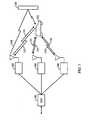
- FIG. 1illustrates the elements of a wireless communication system during a soft handoff operation.
- mobile station 122is in simultaneous communication with base stations 102, 104 and 106.
- a method and apparatus for performing soft handoff in a wireless communication systemis disclosed in the aforementioned U.S. Patent No. 5,101,501 .
- Base station controller 100sends information to be transmitted to remote station 122 as to base stations 102,104 and 106 .
- the forward link traffic datais transmitted to remote station 122 by the selected base station (102, 104 or 106) with the best propagation path to remote station 122.
- Base stations 102,104 and 106transmit forward link signals, including forward link traffic, pilot symbols and overhead data on forward link signals 110 , 114, and 118, respectively.
- forward link signals 110, 114 and 118, as well multipath component signal 108are code division multiple access (CDMA) communications signals.
- CDMAcode division multiple access
- Signal 108illustrates the condition referred to as multipath, whereby the signal transmitted by base station 102 traverses two different propagation paths to remote station 122.
- the first signal 110traverses a line of sight propagation path, while a second signal is reflected from an obstacle 124 as forward link signal 108 .
- multipath componentscan be combined at the receiver to provide an improved estimate of the transmitted data as is disclosed in the aforementioned U.S. Patent No. 5,109,390 .
- Remote station 122transmits data to base stations 102, 104 and 106 on reverse link signals 112, 116 and 120, respectively.
- reverse link signals 112, 116 and 120are CDMA communications signals.
- the reverse link signals received by base stations 102,104 and 106are soft combined in base station controller (BSC) 100 to provide a better estimate of the information transmitted by remote station 122 . It should be noted that reverse link signals 102, 104 and 106 are actually the same signal traversing different propagation paths.
- FIG. 2illustrates a forward link slot of the exemplary embodiment.
- a slotis 1.66 ms in duration.
- the slotincludes two pilot bursts 206 and 214.
- the second pilot burst 214has overhead data 212 and 216 included on both sides of it.
- the overhead data of the exemplary embodimentincludes forward link activity (FAC) information, reverse link busy bits and reverse link power control commands.
- FACforward link activity
- the different overhead dataare distinguished from one another by means of an orthogonal covering. Orthogonal coverings are well known in the art and are disclosed in the aforementioned U.S. Patent No. 5,103,459 .
- Forward link activity informationis a bit that when set indicates that a predetermined number of slots in the future, there will be no forward link traffic data to be transmitted by the base station.
- the reverse link busy bitsindicate that the reverse link capacity limit of the base station has been reached.
- the power control commandsare covered with unique Walsh coverings and request that a particular remote station increase or decrease its transmission energy.
- Forward link datais transmitted in the remainder of the frame in sections 202, 210 and 218.
- FIG. 3is a flowchart describing the received signal combining operations performed by remote station 122 when in soft handoff with a plurality of base stations.
- the multipath components of the forward link signal carrying traffic data to remote station 122are combined.
- only the base station with the best propagation path between it and remote station 122transmits forward link traffic data to remote station 122. If for example base station 102 has the best propagation path to remote station 122, then base station 102 transmits forward link traffic data to remote station 122.
- remote station 122soft combines multipath signals 108 and 110 to provide an improved estimate of the forward link traffic data.
- the soft combiningis performed as a weighted sum wherein the weight of demodulated symbols is determined in proportion to the received signal strength of the signal carrying the symbols.
- the act of soft combining of multipath signalsis described in detail in aforementioned U.S. Patent No. 5,109,390 .
- remote station 122soft combines multipath components of the reverse link busy bits transmitted by each base station in the Active Set of remote station 122 to provide an estimate of the reverse link busy bit transmitted by each base station. It should be noted that the power control commands from different base stations may have different values and so cannot be combined meaningfully. That is base station 102 may have exhausted its reverse link capacity while base station 104 may still have remaining reverse link capacity, and as such would transmit reverse link busy bits having different values.
- the reverse link busy bits from each of base stations 102, 104 and 106are combined to determine a maximum data rate for the next reverse link transmission by remote station 122.
- the remote stationtransmits a reverse link signal only when all of the reverse link busy bits indicate that the base stations in the Active Set have additional reverse link capacity.
- the remote station 122weights the reverse link busy bits in accordance with the signal strength of the base station transmitting the busy bit and determines whether to inhibit it reverse link transmissions based on the weighted sum of the busy bits.
- the remote stationweights the reverse link busy bits in accordance with the signal strength of the base station transmitting the busy bit and determines a maximum reverse link data rate at which to transmit based on the weighted sum of the busy bits.
- remote station 122soft combines the multipath components of the reverse power control bits transmitted by each base station to provide an estimate of the reverse power control bits transmitted by each base station.
- the power control commands from different base stationsmay not be the same value and so cannot be combined meaningfully.
- reverse link signal travelling 114may exceed the energy necessary for reliable transmission of signals to base station 104, while simultaneously the energy of the reverse link signal 112 may be inadequate for reliable reception by base station 102.
- base station 104would transmit an "Up" command, while base station 104 would transmit a "Down” command.
- soft combining of power control commands from different base stationsshould not be performed.
- remote station 122increases its transmission energy only when all of the power control commands transmitted by the base stations in its Active Set request remote station 122 to increase its transmission energy.
- the forward link activity bits (FAC) received on multiple paths from common base stationsare soft combined.
- each of the combined forward activity bitsare then provided to a corresponding SNR calculator which uses the information in its computation of the signal to noise ratio energy for a corresponding base station in the Active Set of remote station 122.
- the estimated signal to noise ratio computation for the slotmust be adjusted to account for this gated portion of the frame during which no signal energy is present.
- FIG. 4is a block diagram illustrating the elements of base stations 102, 104 and 106.
- Forward link traffic datais provided to Walsh spreading element 300 and is covered in accordance with Walsh code (W T ).
- the covered traffic datais then provided to multiplexer 312 .
- W TWalsh code
- the forward link traffic datawill be forward error correction coded using a convolutional encoder, turbo coder or other forward error correction coder that is known in the art.
- thirty two Walsh sequences of length thirty twoare used to cover the forward link transmissions. Generation of and spreading in accordance with Walsh codes is disclosed in aforementioned U.S. Patent No. 5,103,459 .
- a predetermined set of pilot symbolsis provided to Walsh spreading element 302 and, in the exemplary embodiment, covered in accordance with Walsh code zero (W 0 ). Covering by Walsh zero is a no op and may operationally be omitted but is provided for illustrative purposes.
- the covered pilot symbolsare then provided to multiplexer 312.
- the forward activity (FAC) bitis provided to spreading element 304 and covered in accordance with Walsh code one W 1 .
- the reverse link busy bitis provided to Walsh spreading element 306 and covered using Walsh code seventeen (W 17 ).
- up to twenty eight power control commands (PC 1 -PC 29 )are provided to Walsh spreading elements 308a-308n and are covered using Walsh sequences (W 2 -W 15 and W 15 -W 31 ).
- the Walsh spread overhead bits including the FAC, the reverse link busy bit and the power control commandsare summed in summer 310 and provided to multiplexer 312.
- Multiplexer 312inserts into the slot the forward link traffic data and two pilot bursts with the second pilot burst having the overhead bits on either side of it.
- the overhead information on both sides of the second pilot burstare replicas of one another and each are 64 Walsh chips in duration spread using thirty two bit Walsh codes providing four redundant versions of each piece of overhead information.
- each base stationspreads the data for transmission using a different PN sequence.
- each base stationgenerates its PN sequence using different phase offsets of generate using a common PN generator polynomial as is described in the aforementioned U.S. Patent 5,103,459 .
- the datais transmitted in accordance with a QPSK modulation wherein the in-phase and quadrature phase components are spread using to different pseudonoise sequences (PN 1 and PN Q ).
- the PN spread signalis provided to transmitter (TMTR) 316 which up converts, amplifies and filters the signal for transmission through antenna 318.
- FIG. 5illustrates remote station 122 of the present invention.
- the forward link signalis received at antenna 500 and provided through duplexer 502 to receiver (RCVR) 504.
- the received signalis provided to traffic demodulator 506, which demodulates the received signal to provide the forward link traffic data to the user of the remote station.
- the received signalis provided to reverse link busy demodulator 508 which demodulates the signal to provide an estimate of the reverse link busy bits transmitted by each of the base stations in communication with remote station 122.
- the reverse link busy bitsare provided to rate determination element 510.
- rate determination element 510inhibits the transmission of the reverse link signal when any of the busy bits from a base station in the Active Set indicate that the reverse link capacity limit for that base station has been reached.
- rate determination element 510selectively inhibits the reverse link transmissions based on a weighted sum of the received busy bits from the base stations in the Active Set of remote station 122.
- the received busy bitsare weighted in accordance with the energy of the received signals.
- rate determination element 510selects a maximum reverse link data rate based on the received busy bits. For example, if the signal from a base station indicating that it has reached reverse link capacity is very weak, rate determination element 510 may select a non zero reverse link data rate that it estimates will not cause undue interference to the base station due to its poor propagation path to that base station. A signal indicative of either the maximum data rate or an inhibition of the reverse link signal is provided to transmit control processor 520, which determines a set of parameters for transmitting the reverse link signal.
- the mobile stationis aware of a transmission rate profile for the base stations in its Active Set in which each of its potential reverse links transmission rates has a known probability of successful transmission under the condition that the base stations in the Active Set are not in a capacity limit condition.
- the reverse link signalis also provided to reverse link power control demodulator 512.
- Reverse link power control demodulator 512demodulates the received signal and combines the multipath components from common base stations to generate improved estimates of the reverse link power control command transmitted by each of the base stations in the Active Set of remote station 122.
- each remote station in communication with a given base stationdemodulates its reverse link power control commands in accordance with a unique Walsh code assigned to that mobile station. It should be noted that the reverse link power control Walsh codes assigned to the remote station may be different for different base stations in communication with remote station 122.
- the improved estimates of the power control commands from each base stationare provided to power control combiner 518.
- remote station 122increases its transmission energy only when all base stations in the Active Set of remote station 122 transmit power control commands requesting remote station 122 to increase its transmission energy. Otherwise, remote station 122 decreases its transmission energy.
- the present inventionis equally applicable to multi-bit power control systems wherein the base station specifies the amount of the transmission energy adjustment requested.
- power control combiner 514selects the smallest requested increase or largest requested decrease in transmission energy.
- FAC combiner 518combines the FAC bits from multipath components of the forward link signal of a common base station to provide an improved estimate of the FAC bit transmitted by each of the base stations.
- Transmit control processor 520receives each of the FAC bit estimates and adjusts the computation of the signal to noise ratio for each base station based on the estimate of the FAC bit transmitted by that base station. Transmit control processor 520 uses the calculated signal to noise ratio of each of the base stations to select the base station with the best propagation path and to determine the maximum data rate of the transmission.
- transmit control processor 520determines the rate of its next reverse link transmission, an adjustment to its reverse link transmission energy and selects the base station with the best propagation path and the maximum forward link data rate that can be reliably transmitted upon that propagation path. These parameters are provided to transmit subsystem 522 which generates the reverse link signal in accordance therewith.
- the reverse link signal from transmit subsystem 522is provided through duplexer 502 for transmission through antenna 500.
- FIG. 6illustrates the elements of traffic demodulator 506 .
- Searcher 600searches potential PN offsets for strong forward link signals.
- Searcher 600assigns PN despreaders 602 PN offsets to demodulate.
- each of PN despreaders 602despreads the received signal in accordance with a different PN offset and provides the result to a corresponding demultiplexer 604.
- PN despreader 602despreads the received signal in accordance with a single PN sequence used to spread a BPSK signal.
- the present inventionis equally applicable to complex PN despreaders that use two distinct PN code sequences (PN 1 and PN Q ) to complex despread a QPSK signal.
- the implementation of PN despreader 602is well known in the art for both PN despreading of a BPSK signal and complex PN despreading of a QPSK signal.
- Demultiplexer 604separates the pilot burst portion of the received signal and provides the demodulated pilot symbols to synchronization (SYNC) element 606.
- Synchronization element 606determines adjustments to the frequency and phase of a corresponding Walsh demodulator 608. A signal indicative of the adjustments to the phase and frequency are provided to Walsh demodulators 608.
- Demultiplexer 604separates out the portions of the slot carrying forward link traffic data and provides those portions to Walsh demodulator 608.
- Walsh demodulator 608demodulates the receive signal in accordance with the Walsh sequence W T .
- the implementation of Walsh demodulator 608is well known in the art and described in detail in U.S. Patent No. 5,103,459 .
- demodulated forward link symbolsare provided to soft combiner 610 which accumulates the multipath components of the base station transmitting the forward link traffic data to remote station 122.
- the accumulated demodulated symbol energiesare then provided to decoder 612 which decodes the forward traffic data and provides the decoded symbols to the user of remote station 122.
- decoder 612is either a trellis decoder, such as a Viterbi decoder, or a turbo decoder.
- FIG. 7illustrates the elements of reverse link busy bit demodulator 508.
- searcher 600searches potential PN offsets for strong forward link signals. Searcher 600 assigns PN offsets to each PN despreaders 602. As described above, each of PN despreaders 602 despreads the received signal in accordance with a different PN offset and provides the result to a corresponding demultiplexer 704.
- Demultiplexer 704separates the pilot burst portion of the slot and provides the pilot symbols to synchronization (SYNC) element 706.
- Synchronization element 706determines adjustments to the frequency and phase of a corresponding Walsh demodulator 708. A signal indicative of the adjustments to the phase and frequency are provided to Walsh demodulators 708. It will be understood by one skilled in the art that synchronization elements 706 and synchronization elements 606 perform identical operations and are shown as distinct elements for illustrative purposes only.
- Demultiplexer 704separates out the portions of overhead data from the received slot and provides those portions to Walsh demodulator 708.
- Walsh demodulator 708demodulates the received signal in accordance with the Walsh code W 17 .
- the demodulated forward link symbolsare provided to soft combiner 710 which accumulates the multipath symbols from each of the base stations.
- the accumulated symbol energiesare then provided to rate determination logic 510 which operates as described previously.
- FIG. 8illustrates the elements of reverse link power control demodulator 512.
- searcher 600searches potential PN offsets for strong forward link signals. Searcher 600 assigns PN offsets to each PN despreaders 602. As described above, in the exemplary embodiment, each of PN despreaders 602 despreads the received signal in accordance with a different PN offset and provides the result to a corresponding demultiplexer 804.
- Demultiplexer 804separates the pilot burst portion of the slot and provides the pilot symbols to synchronization (SYNC) element 806.
- Synchronization element 806determines adjustments to the frequency and phase of a corresponding Walsh demodulator 808. A signal indicative of the adjustments to the timing phase and frequency are provided to Walsh demodulators 808. It will be understood by one skilled in the art that synchronization elements 806 and synchronization elements 606 perform identical operations and are shown as distinct elements for illustrative purposes only.
- Demultiplexer 804separates out the portions of overhead data from the received slot and provides those portions to Walsh demodulator 808.
- Walsh demodulator 808demodulates the received signal in accordance with a Walsh code that is specific for transmission of the power control signals for a corresponding base station. For example, base station 102 may cover its power control commands to remote station 122 using Walsh code five, while base station 104 may cover its power control commands to remotes station 122 using Walsh code thirteen.
- the multipath components of forward link transmitted from a common base stationare demodulated using a common Walsh code to extract the power control commands from that base station.
- power control commands from different base stationsare demodulated using different Walsh codes.
- the demodulated power control commands from each base stationare provided to soft combiners 810 which accumulate the multipath symbols for a corresponding one of the base stations in its Active Set. The accumulated symbol energies are then provided to power control combiner 514 which operates as described previously.
- FIG. 9illustrates the elements of FAC demodulator 516.
- searcher 600searches potential PN offsets for strong forward link signals. Searcher 600 assigns PN offsets to each PN despreaders 602. As described above, in the exemplary embodiment, each of PN despreaders 602 despreads the received signal in accordance with a different PN offset and provides the result to a corresponding demultiplexer 904.
- Demultiplexer 904separates the pilot burst portion of the slot and provides that to synchronization (SYNC) element 906.
- Synchronization element 906determines adjustments to the frequency and phase of a corresponding Walsh demodulator 908. A signal indicative of the adjustments to the phase and frequency are provided to Walsh demodulators 908. It will be understood by one skilled in the art that synchronization elements 906 and synchronization elements 606 perform identical operations and are shown as distinct elements for illustrative purposes only.
- Demultiplexer 904separates out the portions of overhead data from the received slot and provides those portions to Walsh demodulator 908.
- Walsh demodulator 908demodulates the received signal in accordance with a Walsh code one (W 1 ).
- W 1The demodulated FAC symbols from common base stations are provided to a combiner 910.
- Combiners 910combine the energies of the FAC symbols to provide an improved estimate of the FAC bits for each base station in the Active Set of remote station 122.
- transmit control processor 520determines the data rate of the next reverse link transmission, from remote station 122 generates a signal to adjust the transmission energy of the reverse link signal, selects the base station to send forward link traffic data to remote station 122 and the determines the maximum rate at which the forward link data can be reliably transmitted.
- FIG. 10illustrates the elements of transmit control processor 520 and transmit subsystem 522.
- the combined power control command(PC) is provided to gain adjustment element 1000.
- the power control command in the exemplary embodimentis a single bit up/down command in response to which gain adjustment element 1000 generates a control signal increasing or decreasing the transmission energy of the reverse link signal by adjusting the gain of a variable gain amplifier (not shown) within transmitter (TMTR) 1010.
- the FAC estimates for each base stationare provided to a corresponding signal to noise computers 1002.
- signal to noise computers 1002calculate the signal to noise ratio of the forward link signals from a base station in the Active Set of remote station 122. Slots received without forward link traffic data are incorporated into the signal to noise ratio computation differently from those frames that include forward link traffic data. If the occurrence of frames without forward link traffic data is sufficiently rare, these frames may be excluded from the computation entirely.
- the signal to noise energy of frames without forward link traffic dataare scaled prior to being accumulated into the signal to noise ratio computation.
- the estimates of the signal to noise ratio for the forward link signal from each base stationis provided from signal to noise computers 1002 to DRC control processor 1004.
- DRC control processor 1004selects the base station that has the highest signal to nose ratio and determines a maximum transmission rate in accordance with the signal to noise ratio of the selected base station.
- a signal indicative of the identity of the selected base station and the maximum data rateis generated by DRC control processor 1004 and provided to multiplexer (MUX) 1016.
- the reverse link data rate derated by the method described with respect to equation (1)is determined by rate determination element 510 and provided to reverse link controller 1006.
- Reverse link controller 1006determines the rate at which to transmit its reverse link signal in accordance with this maximum data rate. In the exemplary embodiment, reverse link controller 1006 determines the reverse link data rate in accordance with the maximum data rate, the amount of data queued to be transmitted by remote station 122, and the amount of battery power remaining in remote station 122.
- a signal indicative of the selected reverse link data rateis provided to message generator 1008.
- message generator 1008generates a signal indicative of the selected reverse link data rate and provides the reverse rate indicator (RRI) message to multiplexer 1016 .
- RRIreverse rate indicator
- reverse link controller 1006provides a signal indicative of the selected reverse link data rate to reverse link traffic processing element 1018.
- memory element 1020 in reverse link traffic processing element 1018provides an amount of data for transmission.
- the datais encoded by encoder 1022.
- the encoding rate and encoding algorithm used by encoder 1022may also be selected in response to the selected reverse link data rate.
- the encoded symbolsare provided to interleaver (INT) 1024 which reorders the symbols in accordance with a predetermined interleaving format.
- the interleaved symbolsare provided to Walsh modulator 1026.
- the Walsh modulationis performed using variable length Walsh sequences in which the length of the Walsh sequence (and accordingly the spreading gain) is varied inversely with rate of the reverse link transmission.
- variable length Walsh sequencesis described in detail in U.S. Patent No. 5,571,761 , entitled “SYSTEM AND METHOD FOR ORTHOGONAL SPREAD SPECTRUM SEQUENCE GENERATION IN VARIABLE DATA RATE SYSTEMS", which is assigned to the assignee of the present invention and incorporated by reference herein.
- the Walsh spread reverse link traffic datais provided to complex PN spreader 1012.
- Multiplexer 1016multiplexes the data rate control message and the reverse rate indicator message with pilot symbols and provides the multiplexed data to Walsh modulator 1014.
- Walsh modulator 1014spreads the multiplexed data in accordance with the Walsh code zero and provides the spread data to complex PN spreader 1012.
- the PN spreading of the reverse link signalis performed in accordance with two distinct PN sequences (PN 1 and PN Q ) in order to evenly distribute the load the in-phase and quadrature-phase components of the transmitted QPSK signal.
- PN 1 and PN Qtwo distinct PN sequences
- the implementation of complex PN spreader 1012is disclosed in the aforementioned copending U.S. Patent Application Serial No. 08/886,604 .
- the complex PN spread datais provided to transmitter 1010 which amplifies, filters and upconverts the complex PN spread signal for transmission.
Landscapes
- Engineering & Computer Science (AREA)
- Computer Networks & Wireless Communication (AREA)
- Signal Processing (AREA)
- Quality & Reliability (AREA)
- Mobile Radio Communication Systems (AREA)
- Communication Control (AREA)
- Transceivers (AREA)
- Two-Way Televisions, Distribution Of Moving Picture Or The Like (AREA)
- Optical Communication System (AREA)
- Cable Transmission Systems, Equalization Of Radio And Reduction Of Echo (AREA)
- Meter Arrangements (AREA)
- Selective Calling Equipment (AREA)
- Monitoring And Testing Of Transmission In General (AREA)
Abstract
Description
- The present invention relates to communications. More particularly, the present invention relates to a novel and improved method and apparatus for performing signal combining during soft handoff in a wireless communication system.
- The use of code division multiple access (CDMA) modulation techniques is one of several techniques for facilitating communications in which a large number of system users are present. Other multiple access communication system techniques, such as time division multiple access (TDMA) and frequency division multiple access (FDMA) are known in the art. However, the spread spectrum modulation technique of CDMA has significant advantages over these modulation techniques for multiple access communication systems. The use of CDMA techniques in a multiple access communication system is disclosed in
U.S. Patent No. 4,901,307 , entitled "SPREAD SPECTRUM MULTIPLE ACCESS COMMUNICATION SYSTEM USING SATELLITE OR TERRESTRIAL REPEATERS", assigned to the assignee of the present invention, of which the disclosure thereof is incorporated by reference herein. The use of CDMA techniques in a multiple access communication system is further disclosed inU.S. Patent No. 5,103,459 , entitled "SYSTEM AND METHOD FOR GENERATING SIGNAL WAVEFORMS IN A CDMA CELLULAR TELEPHONE SYSTEM", assigned to the assignee of the present invention, of which the disclosure thereof is incorporated by reference herein. - CDMA by its inherent nature of being a wideband signal offers a form of frequency diversity by spreading the signal energy over a wide bandwidth. Therefore, frequency selective fading affects only a small part of the CDMA signal bandwidth. Space or path diversity is obtained by providing multiple signal paths through simultaneous links from a mobile user through two or more cell-sites. Furthermore, path diversity may be obtained by exploiting the multipath environment through spread spectrum processing by allowing a signal arriving with different propagation delays to be received and processed separately. Examples of path diversity are illustrated in
U.S. Patent No. 5,101,501 entitled "METHOD AND SYSTEM FOR PROVIDING A SOFT HANDOFF IN COMMUNICATIONS IN A CDMA CELLULAR TELEPHONE SYSTEM", andU.S. Patent No. 5,109,390 entitled "DIVERSITY RECEIVER IN A CDMA CELLULAR TELEPHONE SYSTEM", both assigned to the assignee of the present invention and incorporated by reference herein. - A useful method of power control of a mobile in a communication system is to monitor the power of the received signal from the mobile station at a base station. The base station in response to the monitored power level transmits power control bits to the mobile station at regular intervals. A method and apparatus for controlling transmission power in this fashion is disclosed in
U.S. Patent No. 5,056,109 , entitled "METHOD AND APPARATUS FOR CONTROLLING TRANSMISSION POWER IN A CDMA CELLULAR MOBILE TELEPHONE SYSTEM", assigned to the assignee of the present invention, of which the disclosure thereof is incorporated by reference herein. - There has been an increasing demand for wireless communications systems to be able to transmit digital information at high rates. One method for sending high rate digital data from a remote station to a central base station is to allow the remote station to send the data using spread spectrum techniques of CDMA. One method that is proposed is to allow the remote station to transmit its information using a small set of orthogonal channels, this method is described in detail in copending
U.S. Patent Application Serial No. 08/886,604 , entitled "HIGH DATA RATE CDMA WIRELESS COMMUNICATION SYSTEM", assigned to the assignee of the present invention and incorporated by reference herein. - The present invention is a novel and improved method and apparatus describing the combining of signals in a high rate wireless communication system. In the exemplary embodiment, each base station in communication with a remote station transmits forward link data including traffic data, pilot symbols and overhead data. In the exemplary embodiment, the overhead data includes a reverse link busy bit, reverse link power control (RPC) commands and a forward link activity (FAC) bit. The reverse link busy bit indicates when the base station has reached its reverse link capacity limit. The RPC bit indicate to each mobile station in communication with the base station whether their transmission energy should be increased or decreased. The FAC bit is a message that indicates when a base station will have no forward link data to transmit a predetermined number of slots in the future.
- In the exemplary embodiment of the present invention, the forward link traffic is only transmitted from one base station to a given remote station. Thus, there is no soft handoff of the forward link traffic data. The multipath components of the forward link traffic data are combined using a traditional RAKE receiver to provide an improved estimate of the forward link traffic data.
- In the exemplary embodiment of the present invention, the reverse link busy bits are independently generated by each base station and indicative of whether the transmitting base station has reached a reverse link capacity limit. In a first exemplary embodiment, the remote station combines the multipath components of the reverse link busy bits from each of the transmitting base stations in its Active Set and in response transmits a reverse link signal only when all of the reverse link busy bits indicate that the base stations in the remote stations Active Set have reverse link capacity. In a first alternative embodiment, the remote station weights the reverse link busy signals in accordance with the signal strength of the base station transmitting the busy signal and determines whether to transmit based on the weighted sum of the busy signals. In a second alternative embodiment, the remote station weights the reverse link busy signals in accordance with the signal strength of the base station transmitting the busy signal and determines a maximum reverse link data rate based on the weighted sum of the busy signals.
- In the exemplary embodiment, the FAC signals are independently generated. The FAC signals from common base stations, multipath components, are soft combined and decoded. Each of the FAC signals are provided to a corresponding SNR calculator for each base station. The calculated SNR for each base station is used to determine which base station should transmit forward link data to the remote station and at what data rate.
- The features, objects, and advantages of the present invention will become more apparent from the detailed description set forth below when taken in conjunction with the drawings in which like reference characters identify correspondingly throughout and wherein:
FIG. 1 is a diagram illustrating the components and signals of a soft handoff environment;FIG. 2 is an illustration of the forward link slot format of the exemplary embodiment;FIG. 3 is a flowchart illustrating the method of combining signals in the exemplary embodiment;FIG. 4 is a block diagram illustrating the base station transmission system of the exemplary embodiment;FIG. 5 is a block diagram of the remote station of the present invention;FIG. 6 is a block diagram of the traffic demodulator of the exemplary embodiment;FIG. 7 is a block diagram of the reverse link busy bit demodulator of the exemplary embodiment;FIG. 8 is a block diagram power control demodulator of the exemplary embodiment;FIG. 9 is a block diagram of the forward link activity (FAC) demodulator of the exemplary embodiment; andFIG. 10 is a block diagram of the remote station transmission subsystem.FIG. 1 illustrates the elements of a wireless communication system during a soft handoff operation. In the soft handoff condition illustrated inFIG. 1 ,mobile station 122 is in simultaneous communication withbase stations U.S. Patent No. 5,101,501 .Base station controller 100 sends information to be transmitted toremote station 122 as to base stations102,104 and106.- In the exemplary embodiment, the forward link traffic data is transmitted to
remote station 122 by the selected base station(102, 104 or106) with the best propagation path toremote station 122. Base stations102,104 and 106 transmit forward link signals, including forward link traffic, pilot symbols and overhead data onforward link signals forward link signals multipath component signal 108, are code division multiple access (CDMA) communications signals. Signal 108 illustrates the condition referred to as multipath, whereby the signal transmitted bybase station 102 traverses two different propagation paths toremote station 122. Thefirst signal 110 traverses a line of sight propagation path, while a second signal is reflected from anobstacle 124 asforward link signal 108. In a CDMA communications system, multipath components can be combined at the receiver to provide an improved estimate of the transmitted data as is disclosed in the aforementionedU.S. Patent No. 5,109,390 .Remote station 122 transmits data tobase stations reverse link signals remote station 122. It should be noted that reverse link signals102, 104 and106 are actually the same signal traversing different propagation paths.FIG. 2 illustrates a forward link slot of the exemplary embodiment. In the exemplary embodiment, a slot is 1.66 ms in duration. The slot includes two pilot bursts206 and214. The second pilot burst214 hasoverhead data U.S. Patent No. 5,103,459 . Forward link activity information is a bit that when set indicates that a predetermined number of slots in the future, there will be no forward link traffic data to be transmitted by the base station. The reverse link busy bits indicate that the reverse link capacity limit of the base station has been reached. The power control commands are covered with unique Walsh coverings and request that a particular remote station increase or decrease its transmission energy. Forward link data is transmitted in the remainder of the frame insections FIG. 3 is a flowchart describing the received signal combining operations performed byremote station 122 when in soft handoff with a plurality of base stations. Inblock 250, the multipath components of the forward link signal carrying traffic data toremote station 122 are combined. In the exemplary embodiment, only the base station with the best propagation path between it andremote station 122 transmits forward link traffic data toremote station 122. If forexample base station 102 has the best propagation path toremote station 122, thenbase station 102 transmits forward link traffic data toremote station 122. In this example,remote station 122 soft combinesmultipath signals U.S. Patent No. 5,109,390 .- In
block 252,remote station 122 soft combines multipath components of the reverse link busy bits transmitted by each base station in the Active Set ofremote station 122 to provide an estimate of the reverse link busy bit transmitted by each base station. It should be noted that the power control commands from different base stations may have different values and so cannot be combined meaningfully. That isbase station 102 may have exhausted its reverse link capacity whilebase station 104 may still have remaining reverse link capacity, and as such would transmit reverse link busy bits having different values. - In
block 254, The reverse link busy bits from each ofbase stations remote station 122. In a first exemplary embodiment, the remote station transmits a reverse link signal only when all of the reverse link busy bits indicate that the base stations in the Active Set have additional reverse link capacity. In a first alternative embodiment, theremote station 122 weights the reverse link busy bits in accordance with the signal strength of the base station transmitting the busy bit and determines whether to inhibit it reverse link transmissions based on the weighted sum of the busy bits. In a second alternative embodiment, the remote station weights the reverse link busy bits in accordance with the signal strength of the base station transmitting the busy bit and determines a maximum reverse link data rate at which to transmit based on the weighted sum of the busy bits. - In
block 256,remote station 122 soft combines the multipath components of the reverse power control bits transmitted by each base station to provide an estimate of the reverse power control bits transmitted by each base station. It should be noted that the power control commands from different base stations may not be the same value and so cannot be combined meaningfully. For example, reverse link signal travelling114 may exceed the energy necessary for reliable transmission of signals tobase station 104, while simultaneously the energy of thereverse link signal 112 may be inadequate for reliable reception bybase station 102. In this case,base station 104 would transmit an "Up" command, whilebase station 104 would transmit a "Down" command. Thus, soft combining of power control commands from different base stations should not be performed. In the exemplary embodiment, for each base station, a hard decision regarding the value of its power control command is determined. Proceeding to block258, in the exemplary embodiment,remote station 122 increases its transmission energy only when all of the power control commands transmitted by the base stations in its Active Set requestremote station 122 to increase its transmission energy. - In
block 260, the forward link activity bits (FAC) received on multiple paths from common base stations are soft combined. Inblock 262, each of the combined forward activity bits are then provided to a corresponding SNR calculator which uses the information in its computation of the signal to noise ratio energy for a corresponding base station in the Active Set ofremote station 122. Referring back toFIG. 2 , if the slot does not include data then the estimated signal to noise ratio computation for the slot must be adjusted to account for this gated portion of the frame during which no signal energy is present. FIG. 4 is a block diagram illustrating the elements ofbase stations Walsh spreading element 300 and is covered in accordance with Walsh code (WT). The covered traffic data is then provided tomultiplexer 312. It will be understood by one skilled in the art that processing of the signal prior to its provision toWalsh spreading element 300 is within the scope of the present invention. In particular, it is anticipated that the forward link traffic data will be forward error correction coded using a convolutional encoder, turbo coder or other forward error correction coder that is known in the art. In the exemplary embodiment, thirty two Walsh sequences of length thirty two are used to cover the forward link transmissions. Generation of and spreading in accordance with Walsh codes is disclosed in aforementionedU.S. Patent No. 5,103,459 .- A predetermined set of pilot symbols, typically all ones, is provided to
Walsh spreading element 302 and, in the exemplary embodiment, covered in accordance with Walsh code zero (W0). Covering by Walsh zero is a no op and may operationally be omitted but is provided for illustrative purposes. The covered pilot symbols are then provided tomultiplexer 312. - The forward activity (FAC) bit is provided to spreading
element 304 and covered in accordance with Walsh code one W1. The reverse link busy bit is provided toWalsh spreading element 306 and covered using Walsh code seventeen (W17). In addition, up to twenty eight power control commands (PC1-PC29) are provided to Walsh spreading elements308a-308n and are covered using Walsh sequences (W2-W15 and W15-W31). The Walsh spread overhead bits including the FAC, the reverse link busy bit and the power control commands are summed insummer 310 and provided tomultiplexer 312. Multiplexer 312 inserts into the slot the forward link traffic data and two pilot bursts with the second pilot burst having the overhead bits on either side of it. In the exemplary embodiment, the overhead information on both sides of the second pilot burst are replicas of one another and each are 64 Walsh chips in duration spread using thirty two bit Walsh codes providing four redundant versions of each piece of overhead information.- The slot, including the forward link traffic, the pilot bursts and overhead bits, as illustrated in
FIG. 2 are provided toPN spreader 314. In the exemplary embodiment, each base station spreads the data for transmission using a different PN sequence. In the preferred embodiment, each base station generates its PN sequence using different phase offsets of generate using a common PN generator polynomial as is described in the aforementionedU.S. Patent 5,103,459 . In the preferred embodiment, the data is transmitted in accordance with a QPSK modulation wherein the in-phase and quadrature phase components are spread using to different pseudonoise sequences (PN1 and PNQ). The PN spread signal is provided to transmitter (TMTR)316 which up converts, amplifies and filters the signal for transmission throughantenna 318. FIG. 5 illustratesremote station 122 of the present invention. The forward link signal is received atantenna 500 and provided throughduplexer 502 to receiver (RCVR)504. The received signal is provided totraffic demodulator 506, which demodulates the received signal to provide the forward link traffic data to the user of the remote station.- The received signal is provided to reverse link
busy demodulator 508 which demodulates the signal to provide an estimate of the reverse link busy bits transmitted by each of the base stations in communication withremote station 122. The reverse link busy bits are provided to ratedetermination element 510. In the exemplary embodiment,rate determination element 510, inhibits the transmission of the reverse link signal when any of the busy bits from a base station in the Active Set indicate that the reverse link capacity limit for that base station has been reached. In an alternative embodiment,rate determination element 510 selectively inhibits the reverse link transmissions based on a weighted sum of the received busy bits from the base stations in the Active Set ofremote station 122. In the first alternative embodiment, the received busy bits are weighted in accordance with the energy of the received signals. In a second alternative embodiment,rate determination element 510 selects a maximum reverse link data rate based on the received busy bits. For example, if the signal from a base station indicating that it has reached reverse link capacity is very weak,rate determination element 510 may select a non zero reverse link data rate that it estimates will not cause undue interference to the base station due to its poor propagation path to that base station. A signal indicative of either the maximum data rate or an inhibition of the reverse link signal is provided to transmitcontrol processor 520, which determines a set of parameters for transmitting the reverse link signal. - In the preferred embodiment, the mobile station is aware of a transmission rate profile for the base stations in its Active Set in which each of its potential reverse links transmission rates has a known probability of successful transmission under the condition that the base stations in the Active Set are not in a capacity limit condition. In the preferred embodiment,
remote station 122 computes a metric referred to herein as a Derating Metric (DM) in accordance with the equation:
where SNR1 is the estimated signal to noise ratio of the ith base station, Max SNR1 is the maximum signal to noise ratio of the base stations in the Active Set of remote station i, RLB¡ is the value of the reverse link busy bit for the ith base station in the Active set which takes a value of 0 or 1. Usingequation 1, the stronger the forward link signal from a base station transmitting a reverse link busy bit indicating a reverse link capacity limit condition, the greater will be the derating. This derating metric assumes a value of between 0 and 1 which is used to scale the transmission rate profile such that rates are reduced for a given probability of successful transmission. - The reverse link signal is also provided to reverse link
power control demodulator 512. Reverse linkpower control demodulator 512 demodulates the received signal and combines the multipath components from common base stations to generate improved estimates of the reverse link power control command transmitted by each of the base stations in the Active Set ofremote station 122. In the exemplary embodiment, each remote station in communication with a given base station demodulates its reverse link power control commands in accordance with a unique Walsh code assigned to that mobile station. It should be noted that the reverse link power control Walsh codes assigned to the remote station may be different for different base stations in communication withremote station 122. - The improved estimates of the power control commands from each base station are provided to
power control combiner 518. In the exemplary embodiment,remote station 122 increases its transmission energy only when all base stations in the Active Set ofremote station 122 transmit power control commands requestingremote station 122 to increase its transmission energy. Otherwise,remote station 122 decreases its transmission energy. In addition, the present invention is equally applicable to multi-bit power control systems wherein the base station specifies the amount of the transmission energy adjustment requested. In the simplest implementation ofpower control combiner 514 for use in a multi-bit power control system,power control combiner 514 selects the smallest requested increase or largest requested decrease in transmission energy. FAC combiner 518 combines the FAC bits from multipath components of the forward link signal of a common base station to provide an improved estimate of the FAC bit transmitted by each of the base stations. Transmitcontrol processor 520 receives each of the FAC bit estimates and adjusts the computation of the signal to noise ratio for each base station based on the estimate of the FAC bit transmitted by that base station. Transmitcontrol processor 520 uses the calculated signal to noise ratio of each of the base stations to select the base station with the best propagation path and to determine the maximum data rate of the transmission.- Based on the estimates of the reverse link busy bits, the reverse link power control commands, and the forward activity bits, transmit
control processor 520 determines the rate of its next reverse link transmission, an adjustment to its reverse link transmission energy and selects the base station with the best propagation path and the maximum forward link data rate that can be reliably transmitted upon that propagation path. These parameters are provided to transmitsubsystem 522 which generates the reverse link signal in accordance therewith. The reverse link signal from transmitsubsystem 522 is provided throughduplexer 502 for transmission throughantenna 500. FIG. 6 illustrates the elements oftraffic demodulator 506.Searcher 600 searches potential PN offsets for strong forward link signals.Searcher 600 assigns PN despreaders602 PN offsets to demodulate. In the exemplary embodiment, each of PN despreaders602 despreads the received signal in accordance with a different PN offset and provides the result to a corresponding demultiplexer604. In the exemplary embodiment, PN despreader602 despreads the received signal in accordance with a single PN sequence used to spread a BPSK signal. However, the present invention is equally applicable to complex PN despreaders that use two distinct PN code sequences (PN1 and PNQ) to complex despread a QPSK signal. The implementation of PN despreader602 is well known in the art for both PN despreading of a BPSK signal and complex PN despreading of a QPSK signal.- Demultiplexer604 separates the pilot burst portion of the received signal and provides the demodulated pilot symbols to synchronization (SYNC) element606. Synchronization element606 determines adjustments to the frequency and phase of a corresponding Walsh demodulator608. A signal indicative of the adjustments to the phase and frequency are provided to Walsh demodulators608.
- Demultiplexer604 separates out the portions of the slot carrying forward link traffic data and provides those portions to Walsh demodulator608. Walsh demodulator608 demodulates the receive signal in accordance with the Walsh sequence WT. The implementation of Walsh demodulator608 is well known in the art and described in detail in
U.S. Patent No. 5,103,459 . - The demodulated forward link symbols are provided to
soft combiner 610 which accumulates the multipath components of the base station transmitting the forward link traffic data toremote station 122. The accumulated demodulated symbol energies are then provided todecoder 612 which decodes the forward traffic data and provides the decoded symbols to the user ofremote station 122. In the exemplary embodiment,decoder 612 is either a trellis decoder, such as a Viterbi decoder, or a turbo decoder. FIG. 7 illustrates the elements of reverse link busy bit demodulator508. As described with respect toFIG. 6 ,searcher 600 searches potential PN offsets for strong forward link signals.Searcher 600 assigns PN offsets to each PN despreaders602. As described above, each of PN despreaders602 despreads the received signal in accordance with a different PN offset and provides the result to a corresponding demultiplexer704.- Demultiplexer704 separates the pilot burst portion of the slot and provides the pilot symbols to synchronization (SYNC) element706. Synchronization element706 determines adjustments to the frequency and phase of a corresponding Walsh demodulator708. A signal indicative of the adjustments to the phase and frequency are provided to Walsh demodulators708. It will be understood by one skilled in the art that synchronization elements706 and synchronization elements606 perform identical operations and are shown as distinct elements for illustrative purposes only.
- Demultiplexer704 separates out the portions of overhead data from the received slot and provides those portions to Walsh demodulator708. In the exemplary embodiment, Walsh demodulator708. demodulates the received signal in accordance with the Walsh code W17.
- The demodulated forward link symbols are provided to soft combiner710 which accumulates the multipath symbols from each of the base stations. The accumulated symbol energies are then provided to rate
determination logic 510 which operates as described previously. FIG. 8 illustrates the elements of reverse linkpower control demodulator 512. As described with respect toFIG. 6 ,searcher 600 searches potential PN offsets for strong forward link signals.Searcher 600 assigns PN offsets to each PN despreaders602. As described above, in the exemplary embodiment, each of PN despreaders602 despreads the received signal in accordance with a different PN offset and provides the result to a corresponding demultiplexer804.- Demultiplexer804 separates the pilot burst portion of the slot and provides the pilot symbols to synchronization (SYNC) element806. Synchronization element806 determines adjustments to the frequency and phase of a corresponding Walsh demodulator808. A signal indicative of the adjustments to the timing phase and frequency are provided to Walsh demodulators808. It will be understood by one skilled in the art that synchronization elements806 and synchronization elements606 perform identical operations and are shown as distinct elements for illustrative purposes only.
- Demultiplexer804 separates out the portions of overhead data from the received slot and provides those portions to Walsh demodulator808. In the exemplary embodiment, Walsh demodulator808 demodulates the received signal in accordance with a Walsh code that is specific for transmission of the power control signals for a corresponding base station. For example,
base station 102 may cover its power control commands toremote station 122 using Walsh code five, whilebase station 104 may cover its power control commands toremotes station 122 using Walsh code thirteen. Thus, the multipath components of forward link transmitted from a common base station are demodulated using a common Walsh code to extract the power control commands from that base station. Whereas, power control commands from different base stations are demodulated using different Walsh codes. - The demodulated power control commands from each base station are provided to soft combiners810 which accumulate the multipath symbols for a corresponding one of the base stations in its Active Set. The accumulated symbol energies are then provided to
power control combiner 514 which operates as described previously. FIG. 9 illustrates the elements ofFAC demodulator 516. As described with respect toFIG. 6 ,searcher 600 searches potential PN offsets for strong forward link signals.Searcher 600 assigns PN offsets to each PN despreaders602. As described above, in the exemplary embodiment, each of PN despreaders602 despreads the received signal in accordance with a different PN offset and provides the result to a corresponding demultiplexer904.- Demultiplexer904 separates the pilot burst portion of the slot and provides that to synchronization (SYNC) element906. Synchronization element906 determines adjustments to the frequency and phase of a corresponding Walsh demodulator908. A signal indicative of the adjustments to the phase and frequency are provided to Walsh demodulators908. It will be understood by one skilled in the art that synchronization elements906 and synchronization elements606 perform identical operations and are shown as distinct elements for illustrative purposes only.
- Demultiplexer904 separates out the portions of overhead data from the received slot and provides those portions to Walsh demodulator908. In the exemplary embodiment, Walsh demodulator908 demodulates the received signal in accordance with a Walsh code one (W1). The demodulated FAC symbols from common base stations are provided to a combiner910. Combiners910 combine the energies of the FAC symbols to provide an improved estimate of the FAC bits for each base station in the Active Set of
remote station 122. - The maximum data rate from
rate determination element 510, the combined power control command frompower control combiner 514 and the estimated forward activity bits for each of the base stations in the Active set ofremote station 122 are provided to transmitcontrol processor 520. In accordance therewith, transmitcontrol processor 520 determines the data rate of the next reverse link transmission, fromremote station 122 generates a signal to adjust the transmission energy of the reverse link signal, selects the base station to send forward link traffic data toremote station 122 and the determines the maximum rate at which the forward link data can be reliably transmitted. FIG. 10 illustrates the elements of transmitcontrol processor 520 and transmitsubsystem 522. In transmitcontrol processor 520, the combined power control command (PC) is provided to gainadjustment element 1000. The power control command in the exemplary embodiment is a single bit up/down command in response to whichgain adjustment element 1000 generates a control signal increasing or decreasing the transmission energy of the reverse link signal by adjusting the gain of a variable gain amplifier (not shown) within transmitter (TMTR)1010.- The FAC estimates for each base station are provided to a corresponding signal to noise computers1002. In response to the FAC bits, signal to noise computers1002 calculate the signal to noise ratio of the forward link signals from a base station in the Active Set of
remote station 122. Slots received without forward link traffic data are incorporated into the signal to noise ratio computation differently from those frames that include forward link traffic data. If the occurrence of frames without forward link traffic data is sufficiently rare, these frames may be excluded from the computation entirely. In a preferred embodiment, the signal to noise energy of frames without forward link traffic data are scaled prior to being accumulated into the signal to noise ratio computation. - The estimates of the signal to noise ratio for the forward link signal from each base station is provided from signal to noise computers1002 to
DRC control processor 1004.DRC control processor 1004 selects the base station that has the highest signal to nose ratio and determines a maximum transmission rate in accordance with the signal to noise ratio of the selected base station. A signal indicative of the identity of the selected base station and the maximum data rate is generated byDRC control processor 1004 and provided to multiplexer (MUX)1016. - The reverse link data rate derated by the method described with respect to equation (1) is determined by
rate determination element 510 and provided to reverselink controller 1006.Reverse link controller 1006 determines the rate at which to transmit its reverse link signal in accordance with this maximum data rate. In the exemplary embodiment,reverse link controller 1006 determines the reverse link data rate in accordance with the maximum data rate, the amount of data queued to be transmitted byremote station 122, and the amount of battery power remaining inremote station 122. - A signal indicative of the selected reverse link data rate is provided to
message generator 1008. Inresponse message generator 1008 generates a signal indicative of the selected reverse link data rate and provides the reverse rate indicator (RRI) message tomultiplexer 1016. In addition,reverse link controller 1006 provides a signal indicative of the selected reverse link data rate to reverse linktraffic processing element 1018. - In response to the reverse link data rate signal,
memory element 1020 in reverse linktraffic processing element 1018 provides an amount of data for transmission. The data is encoded byencoder 1022. The encoding rate and encoding algorithm used byencoder 1022 may also be selected in response to the selected reverse link data rate. The encoded symbols are provided to interleaver (INT)1024 which reorders the symbols in accordance with a predetermined interleaving format. The interleaved symbols are provided toWalsh modulator 1026. - In the exemplary embodiment, the Walsh modulation is performed using variable length Walsh sequences in which the length of the Walsh sequence (and accordingly the spreading gain) is varied inversely with rate of the reverse link transmission. The use of variable length Walsh sequences is described in detail in
U.S. Patent No. 5,571,761 , entitled "SYSTEM AND METHOD FOR ORTHOGONAL SPREAD SPECTRUM SEQUENCE GENERATION IN VARIABLE DATA RATE SYSTEMS", which is assigned to the assignee of the present invention and incorporated by reference herein. - The Walsh spread reverse link traffic data is provided to
complex PN spreader 1012. Multiplexer1016 multiplexes the data rate control message and the reverse rate indicator message with pilot symbols and provides the multiplexed data to Walsh modulator1014. Walsh modulator1014 spreads the multiplexed data in accordance with the Walsh code zero and provides the spread data tocomplex PN spreader 1012. - In the exemplary embodiment, the PN spreading of the reverse link signal is performed in accordance with two distinct PN sequences (PN1 and PNQ) in order to evenly distribute the load the in-phase and quadrature-phase components of the transmitted QPSK signal. The implementation of
complex PN spreader 1012 is disclosed in the aforementioned copendingU.S. Patent Application Serial No. 08/886,604 . - The complex PN spread data is provided to
transmitter 1010 which amplifies, filters and upconverts the complex PN spread signal for transmission. - The previous description of the preferred embodiments is provided to enable any person skilled in the art to make or use the present invention. The various modifications to these embodiments will be readily apparent to those skilled in the art, and the generic principles defined herein may be applied to other embodiments without the use of the inventive faculty. Thus, the present invention is not intended to be limited to the embodiments shown herein but is to be accorded the widest scope consistent with the principles and novel features disclosed herein.
- 1. In a communication system in which each base station in communication with a remote station transmits a reverse link busy bit indicating whether its reverse link capacity has been exhausted, a method of determining the reverse link transmission rate of said remote stations comprising the steps of:
- determining a reverse link transmission rate in accordance with a combined reverse link busy signal generated in accordance with reverse link busy bits transmitted by each of said base stations; and
- transmitting said reverse link data in accordance with said reverse link transmission rate.
- 2. The method of
paragraph 1 further comprising the step of soft combining multipath components of the reverse link busy bits from each of said base stations to provide said estimate of the reverse link busy bit transmitted by each of said base stations. - 3. The method of
paragraph 1 where said step of determining said reverse link transmission rate, comprises inhibiting the transmission of said reverse link data when any of said reverse link busy bits indicate the base station is in a reverse link capacity condition. - 4. The method of
paragraph 1 where said step of determining said reverse link transmission rate is performed in accordance with the values of the reverse link busy bits transmitted by each base station and the strength of the forward link signals from each base station as received by said remote station. - 5. The method of
paragraph 1 where said step of determining said reverse link transmission rate, comprises the steps of:- computing a derating metric in accordance with the values of the reverse link busy bits transmitted by each base station and the strength of the forward link signals from each base station as received by said remote station; and
- adjusting a rate transmission profile indicative of the probability of successful transmission for each potential reverse link transmission rate in accordance with said derating metric; and
- selecting said reverse link transmission rate in accordance with said adjusted rate transmission profile.
- 6. The method of paragraph 5 where said step of computing said derating metric (DM) is performed in accordance with the equation:

where SNR1 is the estimated signal to noise ratio of the ith base station, Max SNR1 is the maximum signal to noise ratio of the base stations in the Active Set of remote station i, RLBi is the value of the reverse link busy bit for the ith base station in the Active set which takes a value of 0 or 1.


Claims (15)
- A method of communication between a remote station (122) and a plurality of base stations (102, 104, 106) in a soft handoff condition, the method comprising:receiving at the remote station (122) a power control command transmitted by each of the plurality of base stations (102, 104, 106); andincreasing transmission energy of the remote station (122) only when each of the power control commands transmitted by the base stations in an Active Set of the remote station (122) requests an increase in the remote station transmission energy.
- The method of claim 1, further comprising decreasing the remote station transmission energy if at least one of the power control commands transmitted by the base stations in the Active Set of the remote station (122) requests a decrease in the remote station transmission energy.
- The method of claim 1 or 2, wherein the power control commands comprise single-bit commands.
- The method of claim 3, wherein each of the single-bit commands is an up/down command.
- The method of claim 1 or 2, wherein the power control commands comprise multi-bit power control commands.
- The method of claim 5, wherein each of the multi-bit commands specifies an amount of transmission energy adjustment requested.
- The method of claim 6, further comprising increasing the remote station transmission energy by the smallest requested adjustment specified by the multi-bit commands when each of the power control commands transmitted by the base stations in the Active Set of the remote station (122) requests an increase.
- The method of claim 6, further comprising decreasing the remote station transmission energy by the largest requested adjustment specified by the multi-bit commands when at least one of the power control commands transmitted by the base stations in the Active Set of the remote station (122) requests a decrease.
- The method of any preceding claim, further comprising:receiving at the remote station (122) a forward link activity bit transmitted by each of the plurality of base stations (102, 104, 106), each forward link activity bit indicating whether the corresponding base station will have forward link data to transmit over a predetermined number of slots in the future;providing each forward link activity bit to a corresponding signal-to-noise ratio calculator; andcomputing, for each base station, a signal-to-noise ratio using the corresponding forward activity bit.
- A remote station (122) adapted for use in a soft handoff condition in a communication system, the remote station comprising:means for receiving at the remote station (122) a power control command transmitted by each of the plurality of base stations (102, 104, 106); andmeans for increasing transmission energy of the remote station (122) only when each of the power control commands transmitted by the base stations in an Active Set of the remote station (122) requests an increase in the remote station transmission energy.
- The remote station (122) of claim 10, further comprising means for decreasing the remote station transmission energy if at least one of the power control commands transmitted by the base stations in the Active Set of the remote station (122) requests a decrease in the remote station transmission energy.
- The remote station (122) of claim 10 or 11, wherein the power control commands comprise multi-bit power control commands each specifying an amount of transmission energy adjustment requested.
- The remote station (122) of claim 12, further comprising means for increasing the remote station transmission energy by the smallest requested adjustment specified by the multi-bit commands when each of the power control commands transmitted by the base stations in the Active Set of the remote station (122) requests an increase.
- The remote station (122) of claim 12 or 13, further comprising means for decreasing the remote station transmission energy by the largest requested adjustment specified by the multi-bit commands when at least one of the power control commands transmitted by the base stations in the Active Set of the remote station (122) requests a decrease.
- The remote station (122) of any of claims 10 to 14, further comprising:means for receiving at the remote station (122) a forward link activity bit transmitted by each of the plurality of base stations (102, 104, 106), each forward link activity bit indicating whether the corresponding base station will have forward link data to transmit over a predetermined number of slots in the future;means for providing each forward link activity bit to a corresponding signal-to-noise ratio calculator; andmeans for computing, for each base station, a signal-to-noise ratio using the corresponding forward activity bit.
Applications Claiming Priority (3)
| Application Number | Priority Date | Filing Date | Title |
|---|---|---|---|
| US09/346,882US6556549B1 (en) | 1999-07-02 | 1999-07-02 | Method and apparatus for signal combining in a high data rate communication system |
| EP00945128AEP1192749B1 (en) | 1999-07-02 | 2000-06-30 | Method and apparatus for determining a reverse link transmission rate in a wireless communication system |
| EP07002697AEP1791286B1 (en) | 1999-07-02 | 2000-06-30 | Method and apparatus for determining a reverse link transmission rate in a wireless communication system |
Related Parent Applications (3)
| Application Number | Title | Priority Date | Filing Date |
|---|---|---|---|
| EP00945128.7Division | 2000-06-30 | ||
| EP07002697ADivisionEP1791286B1 (en) | 1999-07-02 | 2000-06-30 | Method and apparatus for determining a reverse link transmission rate in a wireless communication system |
| EP07002697.6Division | 2007-02-08 |
Publications (2)
| Publication Number | Publication Date |
|---|---|
| EP2077638A2true EP2077638A2 (en) | 2009-07-08 |
| EP2077638A3 EP2077638A3 (en) | 2011-11-16 |
Family
ID=23361421
Family Applications (3)
| Application Number | Title | Priority Date | Filing Date |
|---|---|---|---|
| EP00945128AExpired - LifetimeEP1192749B1 (en) | 1999-07-02 | 2000-06-30 | Method and apparatus for determining a reverse link transmission rate in a wireless communication system |
| EP07002697AExpired - LifetimeEP1791286B1 (en) | 1999-07-02 | 2000-06-30 | Method and apparatus for determining a reverse link transmission rate in a wireless communication system |
| EP09004254AWithdrawnEP2077638A3 (en) | 1999-07-02 | 2000-06-30 | Method and apparatus for controlling transmission energy in a wireless communication system |
Family Applications Before (2)
| Application Number | Title | Priority Date | Filing Date |
|---|---|---|---|
| EP00945128AExpired - LifetimeEP1192749B1 (en) | 1999-07-02 | 2000-06-30 | Method and apparatus for determining a reverse link transmission rate in a wireless communication system |
| EP07002697AExpired - LifetimeEP1791286B1 (en) | 1999-07-02 | 2000-06-30 | Method and apparatus for determining a reverse link transmission rate in a wireless communication system |
Country Status (21)
| Country | Link |
|---|---|
| US (4) | US6556549B1 (en) |
| EP (3) | EP1192749B1 (en) |
| JP (2) | JP4685302B2 (en) |
| KR (1) | KR100753376B1 (en) |
| CN (2) | CN100367694C (en) |
| AT (2) | ATE430420T1 (en) |
| AU (1) | AU5911500A (en) |
| BR (1) | BRPI0011966B1 (en) |
| CA (1) | CA2377060C (en) |
| CY (1) | CY1107056T1 (en) |
| DE (2) | DE60042136D1 (en) |
| DK (1) | DK1192749T3 (en) |
| ES (2) | ES2275524T3 (en) |
| IL (3) | IL147019A0 (en) |
| MX (1) | MXPA01012708A (en) |
| NO (1) | NO333454B1 (en) |
| PT (1) | PT1192749E (en) |
| RU (1) | RU2262212C2 (en) |
| TW (1) | TWI226163B (en) |
| UA (1) | UA73737C2 (en) |
| WO (1) | WO2001003357A1 (en) |
Families Citing this family (49)
| Publication number | Priority date | Publication date | Assignee | Title |
|---|---|---|---|---|
| AU753505B2 (en)* | 1997-10-30 | 2002-10-17 | Cold Spring Harbor Laboratory | Probe arrays and methods of using probe arrays for distinguishing DNA |
| DE19857406A1 (en)* | 1998-12-12 | 2000-06-15 | Bosch Gmbh Robert | Telecommunication system and data transmission method |
| US6556549B1 (en)* | 1999-07-02 | 2003-04-29 | Qualcomm Incorporated | Method and apparatus for signal combining in a high data rate communication system |
| US6563810B1 (en)* | 1999-09-30 | 2003-05-13 | Qualcomm Incorporated | Closed loop resource allocation |
| GB2363689A (en)* | 2000-05-08 | 2002-01-02 | Motorola Inc | Improving usage of CDMA system capacity |
| KR100605973B1 (en)* | 2000-06-27 | 2006-07-28 | 삼성전자주식회사 | Link adaptation method and device in mobile communication system |
| JP3514217B2 (en)* | 2000-06-29 | 2004-03-31 | 日本電気株式会社 | Turbo decoding method and receiver |
| KR100370098B1 (en)* | 2000-08-10 | 2003-01-29 | 엘지전자 주식회사 | Method for choosing the base station or sector to demand forwarding data in Mobile Station |
| GB2367447B (en)* | 2000-09-27 | 2003-11-05 | Airspan Networks Inc | Transfer of data in a telecommunications system |
| KR100438447B1 (en)* | 2000-10-20 | 2004-07-03 | 삼성전자주식회사 | Burst pilot transmit apparatus and method in mobile communication system |
| US8374218B2 (en) | 2000-12-05 | 2013-02-12 | Google Inc. | Combining signals with a shuffled-hadamard function |
| US8385470B2 (en)* | 2000-12-05 | 2013-02-26 | Google Inc. | Coding a signal with a shuffled-Hadamard function |
| US7545849B1 (en)* | 2003-03-28 | 2009-06-09 | Google Inc. | Signal spectrum spreading and combining system and method |
| KR100800884B1 (en) | 2001-03-29 | 2008-02-04 | 삼성전자주식회사 | Transmission Control Method of Reverse Link in Mobile Communication System |
| US7012886B2 (en)* | 2001-05-16 | 2006-03-14 | Lucent Technologies Inc. | Walsh code allocation/de-allocation system |
| KR100391981B1 (en)* | 2001-06-16 | 2003-07-22 | 삼성전자주식회사 | Apparatus for restoring data from signal transmitted by a plurality of antenna |
| US7221653B2 (en)* | 2001-07-30 | 2007-05-22 | Telefonaktiebolaget Lm Ericsson (Publ) | Fast flow control methods for communication networks |
| US7177265B1 (en)* | 2002-01-15 | 2007-02-13 | Digi International Inc. | Iterative method, and apparatus for acquiring time and frequency synchronization in a DSSS receiver |
| US8009607B2 (en)* | 2002-04-24 | 2011-08-30 | Telefonaktiebolaget Lm Ericsson (Publ) | Method and apparatus for uplink transmission timing in a mobile communications system |
| US7411923B2 (en) | 2002-11-14 | 2008-08-12 | Qualcomm Incorporated | Wireless communication rate shaping |
| CA2765073C (en)* | 2002-11-14 | 2015-04-21 | Qualcomm Incorporated | Wireless communication rate shaping |
| US7411974B2 (en) | 2002-11-14 | 2008-08-12 | Qualcomm Incorporated | Wireless communication rate shaping |
| US7680052B2 (en) | 2002-12-16 | 2010-03-16 | Qualcomm Incorporated | Closed loop resource allocation |
| US7493132B2 (en)* | 2003-02-14 | 2009-02-17 | Qualcomm Incorporated | System and method for uplink rate selection |
| WO2005025262A1 (en)* | 2003-09-04 | 2005-03-17 | Fujitsu Limited | Communication system and handover communication method |
| US9629030B2 (en)* | 2003-10-14 | 2017-04-18 | Qualcomm Incorporated | Data rate control in soft handoff and during cell-switching |
| KR100651466B1 (en) | 2004-01-27 | 2006-11-29 | 삼성전자주식회사 | Synchronization system and method for broadcasting a service stream in a mobile communication system |
| US7693110B2 (en) | 2004-09-16 | 2010-04-06 | Motorola, Inc. | System and method for downlink signaling for high speed uplink packet access |
| US20060068831A1 (en)* | 2004-09-30 | 2006-03-30 | Stewart Kenneth A | Predictive power control in a digital diversity receiver |
| KR20070067221A (en)* | 2004-11-17 | 2007-06-27 | 가부시키가이샤 엔.티.티.도코모 | How to determine the maximum allowed transmission rate, mobile stations and radio base stations |
| US8838115B2 (en)* | 2005-07-20 | 2014-09-16 | Qualcomm Incorporated | Method and apparatus for expanded data rate control indices in a wireless communication system |
| US8953596B2 (en) | 2006-01-06 | 2015-02-10 | Qualcomm Incorporated | Conserving network capacity by releasing QoS resources |
| US8428156B2 (en) | 2006-03-20 | 2013-04-23 | Qualcomm Incorporated | Rate control for multi-channel communication systems |
| RU2306653C1 (en)* | 2006-04-20 | 2007-09-20 | Олег Валерьевич Белянин | Wireless charging system with reverse communication |
| DE602006001110D1 (en)* | 2006-05-12 | 2008-06-19 | Ntt Docomo Inc | Methods and apparatus for interference tolerance signaling and power control using a document signal concept |
| EP2242684B1 (en)* | 2008-02-13 | 2014-10-15 | Bell Helicopter Textron Inc. | Rotorcraft with variable incident wing |
| US20100067435A1 (en)* | 2008-09-18 | 2010-03-18 | Krishna Balachandran | Architecture to support network-wide multiple-in-multiple-out wireless communication over an uplink |
| US9042880B2 (en)* | 2008-12-12 | 2015-05-26 | Alcatel Lucent | Method and apparatus for uploading content over wireless networks |
| US8456996B2 (en)* | 2010-07-30 | 2013-06-04 | Qualcomm Incorporated | Method and apparatus for improved MBMS capacity and link management through robust and performance optimal soft combining |
| US8942750B2 (en) | 2011-01-07 | 2015-01-27 | Apple Inc. | Power control in a mobile device |
| FR3033120B1 (en)* | 2015-02-19 | 2018-03-02 | Sigfox | METHOD AND SYSTEM FOR WIRELESS COMMUNICATION BETWEEN AN ACCESS NETWORK AND A TERMINAL WITH A RANGE OF A PLURALITY OF BASE STATIONS OF SAID NETWORK |
| US10756860B2 (en) | 2018-11-05 | 2020-08-25 | XCOM Labs, Inc. | Distributed multiple-input multiple-output downlink configuration |
| US10812216B2 (en) | 2018-11-05 | 2020-10-20 | XCOM Labs, Inc. | Cooperative multiple-input multiple-output downlink scheduling |
| US10432272B1 (en) | 2018-11-05 | 2019-10-01 | XCOM Labs, Inc. | Variable multiple-input multiple-output downlink user equipment |
| US10659112B1 (en) | 2018-11-05 | 2020-05-19 | XCOM Labs, Inc. | User equipment assisted multiple-input multiple-output downlink configuration |
| US10756795B2 (en) | 2018-12-18 | 2020-08-25 | XCOM Labs, Inc. | User equipment with cellular link and peer-to-peer link |
| US11063645B2 (en) | 2018-12-18 | 2021-07-13 | XCOM Labs, Inc. | Methods of wirelessly communicating with a group of devices |
| US11330649B2 (en) | 2019-01-25 | 2022-05-10 | XCOM Labs, Inc. | Methods and systems of multi-link peer-to-peer communications |
| US10756767B1 (en) | 2019-02-05 | 2020-08-25 | XCOM Labs, Inc. | User equipment for wirelessly communicating cellular signal with another user equipment |
Citations (6)
| Publication number | Priority date | Publication date | Assignee | Title |
|---|---|---|---|---|
| US4901307A (en) | 1986-10-17 | 1990-02-13 | Qualcomm, Inc. | Spread spectrum multiple access communication system using satellite or terrestrial repeaters |
| US5056109A (en) | 1989-11-07 | 1991-10-08 | Qualcomm, Inc. | Method and apparatus for controlling transmission power in a cdma cellular mobile telephone system |
| US5101501A (en) | 1989-11-07 | 1992-03-31 | Qualcomm Incorporated | Method and system for providing a soft handoff in communications in a cdma cellular telephone system |
| US5103459A (en) | 1990-06-25 | 1992-04-07 | Qualcomm Incorporated | System and method for generating signal waveforms in a cdma cellular telephone system |
| US5109390A (en) | 1989-11-07 | 1992-04-28 | Qualcomm Incorporated | Diversity receiver in a cdma cellular telephone system |
| US5571761A (en) | 1986-08-22 | 1996-11-05 | Canon Kabushiki Kaisha | Ceramic substrate circuit substrate |
Family Cites Families (62)
| Publication number | Priority date | Publication date | Assignee | Title |
|---|---|---|---|---|
| US3351859A (en) | 1964-08-19 | 1967-11-07 | Motorola Inc | Communication system employing multipath rejection means |
| US4112257A (en) | 1977-03-24 | 1978-09-05 | Frost Edward G | Comprehensive automatic mobile radio telephone system |
| US4222115A (en) | 1978-03-13 | 1980-09-09 | Purdue Research Foundation | Spread spectrum apparatus for cellular mobile communication systems |
| US4291410A (en) | 1979-10-24 | 1981-09-22 | Rockwell International Corporation | Multipath diversity spread spectrum receiver |
| US4630283A (en) | 1985-07-17 | 1986-12-16 | Rca Corporation | Fast acquisition burst mode spread spectrum communications system with pilot carrier |
| US4672658A (en) | 1985-10-16 | 1987-06-09 | At&T Company And At&T Bell Laboratories | Spread spectrum wireless PBX |
| US4752969A (en) | 1986-01-16 | 1988-06-21 | Kenneth Rilling | Anti-multipath signal processor |
| US4669091A (en) | 1986-02-10 | 1987-05-26 | Rca Corporation | Adaptive multipath distortion equalizer |
| DE3607687A1 (en) | 1986-03-08 | 1987-09-10 | Philips Patentverwaltung | METHOD AND CIRCUIT ARRANGEMENT FOR SWITCHING A RADIO CONNECTION INTO ANOTHER RADIO CELL OF A DIGITAL RADIO TRANSMISSION SYSTEM |
| US4694467A (en) | 1986-07-03 | 1987-09-15 | Signatron, Inc. | Modem for use in multipath communication systems |
| US4710944A (en) | 1986-10-17 | 1987-12-01 | Rca Corporation | Dual transmit-receive space diversity communication system |
| US4797950A (en) | 1986-11-10 | 1989-01-10 | Kenneth Rilling | Multipath reduction system |
| US4736460A (en) | 1986-11-10 | 1988-04-05 | Kenneth Rilling | Multipath reduction system |
| JP2854346B2 (en) | 1989-09-19 | 1999-02-03 | 日本電信電話株式会社 | Channel assignment method |
| US5038399A (en) | 1990-05-21 | 1991-08-06 | Motorola, Inc. | Method for assigning channel reuse levels in a multi-level cellular system |
| US5216675A (en)* | 1990-05-23 | 1993-06-01 | The United States Of America As Represented By The Secretary Of The Air Force | Reliable broadcast protocol |
| US5659569A (en) | 1990-06-25 | 1997-08-19 | Qualcomm Incorporated | Data burst randomizer |
| NZ239283A (en)* | 1990-08-23 | 1994-09-27 | Ericsson Telefon Ab L M | Mobile cellular radio: handoff between half rate and full rate channels according to estimated received signal quality |
| US5297192A (en) | 1990-09-28 | 1994-03-22 | At&T Bell Laboratories | Method and apparatus for remotely programming a mobile data telephone set |
| DE69223961T2 (en) | 1991-06-03 | 1998-07-30 | British Telecommunications P.L.C., London | Radio system |
| ATE211760T1 (en)* | 1992-10-20 | 2002-01-15 | Canon Kk | CARRIER FOR MICROORGANISMS, SOIL DETOXIFYERS USING SUCH CARRIER, AND METHODS FOR DETOXIFICATION OF SOIL |
| DE4302228C2 (en)* | 1993-01-27 | 1999-09-30 | Deutsche Telekom Mobil | Procedure for assigning frequencies to base stations of a mobile radio network |
| AU7173694A (en) | 1993-06-25 | 1995-01-17 | Omniplex, Inc. | Determination of location using time-synchronized cell site transmissions |
| ZA946674B (en)* | 1993-09-08 | 1995-05-02 | Qualcomm Inc | Method and apparatus for determining the transmission data rate in a multi-user communication system |
| US5404376A (en) | 1993-09-09 | 1995-04-04 | Ericsson-Ge Mobile Communications Inc. | Navigation assistance for call handling in mobile telephone systems |
| US5594720A (en) | 1993-11-24 | 1997-01-14 | Lucent Technologies Inc. | Multiple access cellular communication with dynamic slot allocation and reduced co-channel interferences |
| US5533019A (en)* | 1994-01-31 | 1996-07-02 | Motorola, Inc. | Packet data in an analog cellular radiotelephone system |
| US5491837A (en) | 1994-03-07 | 1996-02-13 | Ericsson Inc. | Method and system for channel allocation using power control and mobile-assisted handover measurements |
| JP3302168B2 (en) | 1994-04-05 | 2002-07-15 | 株式会社東芝 | Mobile radio communication system |
| US5442625A (en) | 1994-05-13 | 1995-08-15 | At&T Ipm Corp | Code division multiple access system providing variable data rate access to a user |
| US5638412A (en) | 1994-06-15 | 1997-06-10 | Qualcomm Incorporated | Method for providing service and rate negotiation in a mobile communication system |
| FI96557C (en)* | 1994-09-27 | 1996-07-10 | Nokia Telecommunications Oy | Method for data transmission in a TDMA mobile radio system and a mobile radio system for carrying out the method |
| US5621723A (en)* | 1994-09-27 | 1997-04-15 | Gte Laboratories Incorporated | Power control in a CDMA network |
| US5822359A (en) | 1994-10-17 | 1998-10-13 | Motorola, Inc. | Coherent random access channel in a spread-spectrum communication system and method |
| JP2655108B2 (en) | 1994-12-12 | 1997-09-17 | 日本電気株式会社 | CDMA transceiver |
| JPH08256102A (en) | 1995-01-19 | 1996-10-01 | Sony Corp | Cellular system |
| US5515013A (en)* | 1995-04-18 | 1996-05-07 | Sierra Wireless | Fixed compromise equalization for a dual port FM modulator |
| FI100575B (en) | 1995-05-17 | 1997-12-31 | Nokia Mobile Phones Ltd | Method for improving handover and connection reliability and cellular radio system |
| US6240124B1 (en)* | 1995-06-06 | 2001-05-29 | Globalstar L.P. | Closed loop power control for low earth orbit satellite communications system |
| MY112320A (en)* | 1995-06-19 | 2001-05-31 | Qualcomm Inc | Method and appatratus for managing load conditions in a local wireless loop system |
| US5779071A (en)* | 1995-08-04 | 1998-07-14 | New Vent Designs, Inc. | Nursing bottle with an air venting structure |
| US5734646A (en)* | 1995-10-05 | 1998-03-31 | Lucent Technologies Inc. | Code division multiple access system providing load and interference based demand assignment service to users |
| JP3078216B2 (en) | 1995-12-13 | 2000-08-21 | 株式会社エヌ・ティ・ティ・ドコモ | Base station selection method |
| US5774809A (en) | 1996-02-12 | 1998-06-30 | Nokia Mobile Phones Limited | Simplified mobile assisted handoff of signal between cells |
| KR100211952B1 (en)* | 1996-12-13 | 1999-08-02 | 정선종 | Reverse link power control method and device in CDMA system |
| US5963548A (en)* | 1997-01-21 | 1999-10-05 | Nokia Mobile Phones Limited | Apparatus and method for configuring a data channel for symmetric/asymmetric data transmission |
| US5878038A (en) | 1997-02-28 | 1999-03-02 | Motorola, Inc. | Method in a wireless code division multiple access communication system for delivering a message to a mobile communication unit |
| KR100206477B1 (en)* | 1997-03-13 | 1999-07-01 | 윤종용 | Method for control changing rate of transmiting power level in cdma system |
| US5914950A (en)* | 1997-04-08 | 1999-06-22 | Qualcomm Incorporated | Method and apparatus for reverse link rate scheduling |
| US5923650A (en) | 1997-04-08 | 1999-07-13 | Qualcomm Incorporated | Method and apparatus for reverse link rate scheduling |
| US6094428A (en)* | 1997-04-30 | 2000-07-25 | Motorola, Inc. | Method and apparatus for transmission and reception of a transmission rate in a CDMA communication system |
| WO1998052365A2 (en)* | 1997-05-14 | 1998-11-19 | Qualcomm Incorporated | Subscriber unit with plural control and data sources for cdma wireless communication system |
| US6134231A (en)* | 1997-08-08 | 2000-10-17 | Telefonaktiebolaget Lm Ericsson (Publ) | Uplink channel puncturing for reduced interference within a wireless data communications network |
| US6035196A (en)* | 1997-08-25 | 2000-03-07 | The Whitaker Corporation | Automatic cell transfer based on reverse channel characteristics |
| US6236646B1 (en)* | 1997-09-09 | 2001-05-22 | Telefonaktiebolaget Lm Ericsson (Publ) | Packet data communications scheduling in a spread spectrum communications system |
| KR100265585B1 (en)* | 1997-10-09 | 2000-09-15 | 정태기 | The power control device of reverse link control channel in mobile telecommunition |
| KR100290668B1 (en)* | 1997-10-13 | 2001-07-12 | 윤종용 | Method for controlling forward link power in cdma system |
| US6574211B2 (en)* | 1997-11-03 | 2003-06-03 | Qualcomm Incorporated | Method and apparatus for high rate packet data transmission |
| US6009553A (en)* | 1997-12-15 | 1999-12-28 | The Whitaker Corporation | Adaptive error correction for a communications link |
| US6147964A (en)* | 1998-05-07 | 2000-11-14 | Qualcomm Inc. | Method and apparatus for performing rate determination using orthogonal rate-dependent walsh covering codes |
| GB9808368D0 (en) | 1998-04-22 | 1998-06-17 | Roke Manor Research | Power control and radio information method for a mobile radio communications system |
| US6556549B1 (en)* | 1999-07-02 | 2003-04-29 | Qualcomm Incorporated | Method and apparatus for signal combining in a high data rate communication system |
- 1999
- 1999-07-02USUS09/346,882patent/US6556549B1/ennot_activeExpired - Lifetime
- 2000
- 2000-06-30JPJP2001508101Apatent/JP4685302B2/ennot_activeExpired - Lifetime
- 2000-06-30PTPT00945128Tpatent/PT1192749E/enunknown
- 2000-06-30CNCNB008099863Apatent/CN100367694C/ennot_activeExpired - Lifetime
- 2000-06-30DEDE60042136Tpatent/DE60042136D1/ennot_activeExpired - Lifetime
- 2000-06-30EPEP00945128Apatent/EP1192749B1/ennot_activeExpired - Lifetime
- 2000-06-30EPEP07002697Apatent/EP1791286B1/ennot_activeExpired - Lifetime
- 2000-06-30EPEP09004254Apatent/EP2077638A3/ennot_activeWithdrawn
- 2000-06-30UAUA2001128824Apatent/UA73737C2/enunknown
- 2000-06-30ATAT07002697Tpatent/ATE430420T1/ennot_activeIP Right Cessation
- 2000-06-30RURU2002102708/09Apatent/RU2262212C2/enactive
- 2000-06-30WOPCT/US2000/018322patent/WO2001003357A1/enactiveApplication Filing
- 2000-06-30BRBRPI0011966Apatent/BRPI0011966B1/enactiveIP Right Grant
- 2000-06-30ESES00945128Tpatent/ES2275524T3/ennot_activeExpired - Lifetime
- 2000-06-30DEDE60034338Tpatent/DE60034338T2/ennot_activeExpired - Lifetime
- 2000-06-30ATAT00945128Tpatent/ATE359631T1/enactive
- 2000-06-30KRKR1020017016813Apatent/KR100753376B1/ennot_activeExpired - Lifetime
- 2000-06-30MXMXPA01012708Apatent/MXPA01012708A/enactiveIP Right Grant
- 2000-06-30ILIL14701900Apatent/IL147019A0/enactiveIP Right Grant
- 2000-06-30ESES07002697Tpatent/ES2325182T3/ennot_activeExpired - Lifetime
- 2000-06-30DKDK00945128Tpatent/DK1192749T3/enactive
- 2000-06-30CACA2377060Apatent/CA2377060C/ennot_activeExpired - Lifetime
- 2000-06-30CNCN200710300536.5Apatent/CN101188476B/ennot_activeExpired - Lifetime
- 2000-06-30AUAU59115/00Apatent/AU5911500A/ennot_activeAbandoned
- 2001
- 2001-02-19TWTW089113095Apatent/TWI226163B/ennot_activeIP Right Cessation
- 2001-12-10ILIL147019Apatent/IL147019A/ennot_activeIP Right Cessation
- 2001-12-28NONO20016409Apatent/NO333454B1/ennot_activeIP Right Cessation
- 2002
- 2002-11-19USUS10/300,392patent/US6807161B2/ennot_activeExpired - Lifetime
- 2002-11-19USUS10/300,391patent/US6680926B2/ennot_activeExpired - Lifetime
- 2003
- 2003-02-04USUS10/357,986patent/US6804210B2/ennot_activeExpired - Lifetime
- 2007
- 2007-06-21CYCY20071100818Tpatent/CY1107056T1/enunknown
- 2008
- 2008-02-03ILIL189208Apatent/IL189208A0/enunknown
- 2010
- 2010-11-08JPJP2010249972Apatent/JP4886065B2/ennot_activeExpired - Lifetime
Patent Citations (7)
| Publication number | Priority date | Publication date | Assignee | Title |
|---|---|---|---|---|
| US5571761A (en) | 1986-08-22 | 1996-11-05 | Canon Kabushiki Kaisha | Ceramic substrate circuit substrate |
| US4901307A (en) | 1986-10-17 | 1990-02-13 | Qualcomm, Inc. | Spread spectrum multiple access communication system using satellite or terrestrial repeaters |
| US5056109A (en) | 1989-11-07 | 1991-10-08 | Qualcomm, Inc. | Method and apparatus for controlling transmission power in a cdma cellular mobile telephone system |
| US5101501A (en) | 1989-11-07 | 1992-03-31 | Qualcomm Incorporated | Method and system for providing a soft handoff in communications in a cdma cellular telephone system |
| US5109390A (en) | 1989-11-07 | 1992-04-28 | Qualcomm Incorporated | Diversity receiver in a cdma cellular telephone system |
| US5103459A (en) | 1990-06-25 | 1992-04-07 | Qualcomm Incorporated | System and method for generating signal waveforms in a cdma cellular telephone system |
| US5103459B1 (en) | 1990-06-25 | 1999-07-06 | Qualcomm Inc | System and method for generating signal waveforms in a cdma cellular telephone system |
Also Published As
Similar Documents
| Publication | Publication Date | Title |
|---|---|---|
| EP1791286B1 (en) | Method and apparatus for determining a reverse link transmission rate in a wireless communication system | |
| EP1163739B1 (en) | Methods and apparatuses for controlling transmission power while in soft handoff | |
| US6603746B1 (en) | Method and apparatus for controlling transmitted power in a wireless communications system | |
| US6414948B1 (en) | Electric power controlling system for variable bit rate CDMA transmission and mobile telephone system | |
| KR20020016936A (en) | Method and apparatus for determining the closed loop power control set point in a wireless packet data communication system | |
| JP2000196522A (en) | Apparatus and method for generating control signal | |
| HK1133500A (en) | Method and apparatus for controlling transmission energy in a wireless communication system | |
| HK1109821B (en) | Method and apparatus for determining a reverse link transmission rate in a wireless communication system | |
| WO2000079700A2 (en) | Method and apparatus for controlling transmission power in a cdma communication system | |
| HK1075767B (en) | Method and apparatus for determining a reverse link transmission rate in a wireless communication system | |
| HK1117969A (en) | Method and apparatus for determining a reverse link transmission rate in a wireless communication system |
Legal Events
| Date | Code | Title | Description |
|---|---|---|---|
| PUAI | Public reference made under article 153(3) epc to a published international application that has entered the european phase | Free format text:ORIGINAL CODE: 0009012 | |
| AC | Divisional application: reference to earlier application | Ref document number:1791286 Country of ref document:EP Kind code of ref document:P Ref document number:1192749 Country of ref document:EP Kind code of ref document:P | |
| AK | Designated contracting states | Kind code of ref document:A2 Designated state(s):AT BE CH CY DE DK ES FI FR GB GR IE IT LI LU MC NL PT SE | |
| AX | Request for extension of the european patent | Extension state:AL LT LV MK RO SI | |
| REG | Reference to a national code | Ref country code:HK Ref legal event code:DE Ref document number:1133500 Country of ref document:HK | |
| PUAL | Search report despatched | Free format text:ORIGINAL CODE: 0009013 | |
| AK | Designated contracting states | Kind code of ref document:A3 Designated state(s):AT BE CH CY DE DK ES FI FR GB GR IE IT LI LU MC NL PT SE | |
| AX | Request for extension of the european patent | Extension state:AL LT LV MK RO SI | |
| RIC1 | Information provided on ipc code assigned before grant | Ipc:H04W 28/22 20090101ALI20111010BHEP Ipc:H04W 52/40 20090101AFI20111010BHEP | |
| 17P | Request for examination filed | Effective date:20120314 | |
| AKX | Designation fees paid | Designated state(s):AT BE CH CY DE DK ES FI FR GB GR IE IT LI LU MC NL PT SE | |
| 17Q | First examination report despatched | Effective date:20130805 | |
| REG | Reference to a national code | Ref country code:HK Ref legal event code:WD Ref document number:1133500 Country of ref document:HK | |
| GRAP | Despatch of communication of intention to grant a patent | Free format text:ORIGINAL CODE: EPIDOSNIGR1 | |
| RIC1 | Information provided on ipc code assigned before grant | Ipc:H04B 7/26 20060101ALI20160406BHEP Ipc:H04W 28/22 20090101ALI20160406BHEP Ipc:H04W 52/40 20090101ALI20160406BHEP Ipc:H04W 28/08 20090101ALN20160406BHEP Ipc:H04L 1/00 20060101AFI20160406BHEP | |
| INTG | Intention to grant announced | Effective date:20160426 | |
| STAA | Information on the status of an ep patent application or granted ep patent | Free format text:STATUS: THE APPLICATION IS DEEMED TO BE WITHDRAWN | |
| 18D | Application deemed to be withdrawn | Effective date:20160907 |