EP2077380B1 - Engine system having valve actuated particle filter regeneration - Google Patents
Engine system having valve actuated particle filter regenerationDownload PDFInfo
- Publication number
- EP2077380B1 EP2077380B1EP08022097AEP08022097AEP2077380B1EP 2077380 B1EP2077380 B1EP 2077380B1EP 08022097 AEP08022097 AEP 08022097AEP 08022097 AEP08022097 AEP 08022097AEP 2077380 B1EP2077380 B1EP 2077380B1
- Authority
- EP
- European Patent Office
- Prior art keywords
- engine
- exhaust valve
- stroke
- air
- piston
- Prior art date
- Legal status (The legal status is an assumption and is not a legal conclusion. Google has not performed a legal analysis and makes no representation as to the accuracy of the status listed.)
- Active
Links
Images

Classifications
- F—MECHANICAL ENGINEERING; LIGHTING; HEATING; WEAPONS; BLASTING
- F02—COMBUSTION ENGINES; HOT-GAS OR COMBUSTION-PRODUCT ENGINE PLANTS
- F02D—CONTROLLING COMBUSTION ENGINES
- F02D13/00—Controlling the engine output power by varying inlet or exhaust valve operating characteristics, e.g. timing
- F02D13/02—Controlling the engine output power by varying inlet or exhaust valve operating characteristics, e.g. timing during engine operation
- F02D13/0242—Variable control of the exhaust valves only
- F02D13/0249—Variable control of the exhaust valves only changing the valve timing only
- F—MECHANICAL ENGINEERING; LIGHTING; HEATING; WEAPONS; BLASTING
- F01—MACHINES OR ENGINES IN GENERAL; ENGINE PLANTS IN GENERAL; STEAM ENGINES
- F01N—GAS-FLOW SILENCERS OR EXHAUST APPARATUS FOR MACHINES OR ENGINES IN GENERAL; GAS-FLOW SILENCERS OR EXHAUST APPARATUS FOR INTERNAL-COMBUSTION ENGINES
- F01N3/00—Exhaust or silencing apparatus having means for purifying, rendering innocuous, or otherwise treating exhaust
- F01N3/02—Exhaust or silencing apparatus having means for purifying, rendering innocuous, or otherwise treating exhaust for cooling, or for removing solid constituents of, exhaust
- F01N3/021—Exhaust or silencing apparatus having means for purifying, rendering innocuous, or otherwise treating exhaust for cooling, or for removing solid constituents of, exhaust by means of filters
- F01N3/023—Exhaust or silencing apparatus having means for purifying, rendering innocuous, or otherwise treating exhaust for cooling, or for removing solid constituents of, exhaust by means of filters using means for regenerating the filters, e.g. by burning trapped particles
- F—MECHANICAL ENGINEERING; LIGHTING; HEATING; WEAPONS; BLASTING
- F02—COMBUSTION ENGINES; HOT-GAS OR COMBUSTION-PRODUCT ENGINE PLANTS
- F02D—CONTROLLING COMBUSTION ENGINES
- F02D13/00—Controlling the engine output power by varying inlet or exhaust valve operating characteristics, e.g. timing
- F02D13/02—Controlling the engine output power by varying inlet or exhaust valve operating characteristics, e.g. timing during engine operation
- F02D13/0253—Fully variable control of valve lift and timing using camless actuation systems such as hydraulic, pneumatic or electromagnetic actuators, e.g. solenoid valves
- F—MECHANICAL ENGINEERING; LIGHTING; HEATING; WEAPONS; BLASTING
- F02—COMBUSTION ENGINES; HOT-GAS OR COMBUSTION-PRODUCT ENGINE PLANTS
- F02D—CONTROLLING COMBUSTION ENGINES
- F02D13/00—Controlling the engine output power by varying inlet or exhaust valve operating characteristics, e.g. timing
- F02D13/02—Controlling the engine output power by varying inlet or exhaust valve operating characteristics, e.g. timing during engine operation
- F02D13/0273—Multiple actuations of a valve within an engine cycle
- Y—GENERAL TAGGING OF NEW TECHNOLOGICAL DEVELOPMENTS; GENERAL TAGGING OF CROSS-SECTIONAL TECHNOLOGIES SPANNING OVER SEVERAL SECTIONS OF THE IPC; TECHNICAL SUBJECTS COVERED BY FORMER USPC CROSS-REFERENCE ART COLLECTIONS [XRACs] AND DIGESTS
- Y02—TECHNOLOGIES OR APPLICATIONS FOR MITIGATION OR ADAPTATION AGAINST CLIMATE CHANGE
- Y02T—CLIMATE CHANGE MITIGATION TECHNOLOGIES RELATED TO TRANSPORTATION
- Y02T10/00—Road transport of goods or passengers
- Y02T10/10—Internal combustion engine [ICE] based vehicles
- Y02T10/12—Improving ICE efficiencies
Definitions
- the present disclosureis directed to an engine system and, more particularly, to an engine system having valve actuated filter regeneration.
- a fuel and air mixtureis combusted within cylinders of an internal combustion engine.
- Reciprocating pistonsare moved between top dead center and bottom dead center positions within the cylinders by a crankshaft of the engine.
- each pistonmoves toward its top dead center position, it compresses the fuel and air mixture.
- the compressed mixturecombusts, it expands and drives the piston downward toward its bottom dead center position.
- Combustion within the cylinderreleases energy and generates combustion products and by-products, most of which are exhausted from the cylinder into an exhaust system of the engine during an exhaust stroke of the piston.
- the combustion products and by-productsare composed of gaseous compounds (e.g., NOx and HC) and solid particulate matter.
- One way to reduce the amount of harmful emissions directed to the atmosphereincludes reducing the amount of oxygen available for combustion.
- a reduction in oxygenresults in a lower combustion temperature that causes a proportional reduction in NOx generation.
- the reduction in oxygenwas achieved by delaying the closing of an intake valve at the beginning of a compression stroke of an engine piston. During the ensuing upward stroke of the piston, some of the air drawn into the cylinder during the previous intake stroke was then pushed back out into the intake manifold.
- the compressed airbeing forced back into an intake manifold of the engine interrupted incoming air flow and resulted in a drop in turbocharger efficiency.
- Another method used by engine manufacturers to reduce emissionsis to trap exhaust particulates with a filter medium (e.g., metal mesh or porous ceramic) and/or convert the gaseous compound to innocuous constituents. Since excessive accumulation of particulate matter on the filter medium will shorten the service life of a particulate trap and increase engine back pressure, the particulate matter must be periodically removed from the medium.
- the method of removing particulate matter from a particulate trapis known as regeneration. Regeneration involves burning off excessive accumulations of particulate matter. This burning off of particulates requires air to facilitate combustion. Typically, air is provided to the particulate trap by a dedicated air supply, which may be expensive, complex, and may perform with low reliability.
- the system of the '755 patentmay improve filter regeneration, its applicability may be limited. That is, it may only be applicable to gasoline or HCCI (homogeneous charge compression ignition) engines having an already combined mixture of air and fuel at the start of the compression stroke. In a standard diesel engine, fuel is not injected or mixed with the air until the end of the compression stroke. As a result, if applied to a diesel engine, the system of the '755 patent would deliver only air to the filter and no regeneration would occur. In addition, because the '755 patent directs both fuel and air to the filter, the engine may experience a loss in power during the regeneration process. The system does nothing to reduce NOx because both air and fuel are being reduced, and not just the air (i.e., the air/fuel ratio is not changing), and NOx reduction requires less air or lower temperature as compared to the fuel during combustion.
- HCCIhomogeneous charge compression ignition
- WO 2005/003536discloses an emission control device for a diesel engine which can be retrofitted.
- an exhaust valveis opened when the piston approaches a bottom dead center. Exhaust from the exhaust manifold flows backward in the corresponding cylinder, thus providing benefits of exhaust gas recirculation.
- DE 100 02 483discloses a device and a method of heating exhaust treatment devices associated with a spark ignition engine.
- the spark ignition enginecomprises variably controllable intake and exhaust valves.
- the exhaust valveis opened during the compression stroke for a short time. Opening of the exhaust valve is controlled in top modes a) before fuel injection into the combustion chamber (secondary air induction); and b) after fuel injection into the combustion chamber (controlled afterburning of an air/fuel mixture).
- the present disclosureis directed to overcoming one or more of the problems set forth above.
- the present disclosureis directed toward an engine.
- the engineincludes an engine block at least partially forming a combustion chamber, and a piston located to reciprocate within the combustion chamber.
- the enginealso includes an exhaust valve fluidly connected to the combustion chamber, and a filter assembly fluidly connected to the exhaust valve.
- the enginefurther includes a controller configured to open the exhaust valve during a portion of an intake stroke of the piston and a portion of a compression stroke of the piston to reduce an amount of air available for combustion during an ensuing power stroke, wherein the exhaust valve opens at the end of the intake stroke and closes during a first half of the compression stroke.
- the present disclosureis directed toward, a method for controlling engine emissions.
- the methodincludes directing air into a cylinder during an intake stroke.
- the methodalso includes releasing a portion of the intake air to an aftertreatment device to reduce an amount of air available for combustion within the cylinder, wherein releasing the portion of the intake air occurs at the end of the intake stroke and ends during a first half of the compression stroke.
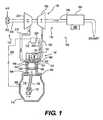
- Fig. 1illustrates an exemplary engine 110 having an emissions reduction system 100.
- Engine 110may be any kind of engine, such as a gasoline engine, a compression ignition diesel engine, or a gaseous fuel-powered engine.
- Engine 110may include an intake 130 configured to direct air and/or fuel into a plurality of cylinders 120 (only one shown) of engine 110, and an exhaust 135 configured to direct combustion by-products from cylinders 120 to the atmosphere.
- Engine 110may be naturally aspirated or may include forced induction via turbocharging or supercharging.
- Engine 110may include an engine block 104 that at least partially defines cylinders 120.
- Engine 110may also include a piston 106 slidably disposed within each cylinder 120, and a cylinder head 122 that caps a top of cylinder 120.
- a combustion chamber 124may be formed between a top of piston 106, walls of cylinder 120, and a bottom of cylinder head 122.
- a crankshaft 112may be rotatably supported within engine block 104 by way of a plurality of journal bearings (not shown).
- a connecting rod 108may connect each piston 106 to crankshaft 112 so that a sliding motion of piston 106 within each respective cylinder 120 results in a rotation of crankshaft 112.
- a fuel injector 123may be seated within cylinder head 122, serving to inject fuel into combustion chamber 124.
- An oil pan 116may be connected to engine block 104 to form a cavity known as a crankcase 118 located below cylinders 120.
- Lubricantmay be provided from oil pan 116 to engine surfaces to minimize metal-on-metal contact and inhibit damage to the surfaces.
- Oil pan 116may serve as a sump for collecting and supplying this lubricant.
- Intake 130may include an air filter 202 serving to clean ambient air drawn into engine 110.
- a conduit 204may connect air filter 202 to a compressor 200, where compressor 200 may be driven by a turbine 190 located within exhaust 135.
- Compressor 200may operate to compress ambient air and deliver the compressed air through a conduit 210 to combustion chamber 124 via an intake manifold 140.
- the flow of air into combustion chamber 124may be regulated by an intake valve 145.
- Intake valve 145may be seated within cylinder head 122 and may be any suitable type of valve known in the art such as, for example, a poppet valve actuated by a cam.
- Conduit 210may include a cooler (not shown), if desired.
- the coolermay serve to cool gases within conduit 210, and, thereby, increase the density of the gases and the amount of air supplied to engine 110.
- the flow of air through conduits 204 and 210may be controlled by a venturi (not shown) or a throttle valve (not shown), if desired.
- Exhaust 135may include an exhaust valve 155, similar to intake valve 145, which may also be seated within cylinder head 122. Exhaust 135 may further include a first exhaust conduit 160 connecting an exhaust manifold 150 of engine 110 to turbine 190. Turbine 190 may receive exhaust gases from engine 110 through first exhaust conduit 160, causing turbine 190 to rotate. As described above, the rotation of turbine 190 may drive compressor 200, turbine 190 together with compressor 200 forming a turbocharger 180.
- a second exhaust conduit 240may connect turbine 190 to a downstream-located filter assembly 260.
- Filter assembly 260may include any suitable filtration media, absorber, reducer, and/or catalytic converter known in the art for reducing the toxicity of emissions from engine 110. Soot carried by exhaust from combustion chamber 124 may collect within filter assembly 260 and require periodic regeneration. Regeneration of the filtration media may include combustion of the trapped soot.
- Filter assembly 260may also include a heater 265. Heater 265 may be any suitable heater known in the art such as, for example, a fuel-fired or electric heater, serving to raise the temperature within filter assembly 260 to promote the combustion of soot.
- An exhaust outletmay connect filter assembly 260 to the atmosphere.
- Emissions reduction system 100may also include a controller 310 in communication with engine 110.
- Controller 310may be any type of programmable logic controller known in the art for automating machine processes, such as a switch, a process logic controller, or a digital circuit. Controller 310 may be made from any material known in the art for logic control devices, and may include a protective housing of metal, plastic, or another durable material. Controller 310 may also include input/output arrangements that allow it to be connected to sensors (not shown). The sensors may be situated to monitor various engine parameters, such as ignition timing, fuel opening pressure, crankshaft rotation (crank senior) and cam rotation (cam senior), intake manifold temperature/pressure, cylinder pressure, engine temperature, exhaust manifold temperature/pressure, filter assembly temperature, and exhaust back pressure, if desired.
- engine parameterssuch as ignition timing, fuel opening pressure, crankshaft rotation (crank senior) and cam rotation (cam senior), intake manifold temperature/pressure, cylinder pressure, engine temperature, exhaust manifold temperature/pressure, filter assembly temperature, and exhaust back pressure,
- Controller 310may be connected by an electrical line 330 to an actuator 157 situated to selectively interrupt the cam-driven motion of exhaust valve 155.
- Actuator 157may be any suitable type of actuator known in the art such as, for example, a selectively actuated cam, a hydraulic cylinder actuator, and/or an electromagnetic actuator. Actuator 157 may open, close, or hold stationary exhaust valve 155 in coordination with the movements of piston 106, as described below.
- Controller 310may serve to control the movement of exhaust valve 155 based on instructions or algorithms stored in memory, input from sensors, and/or other methods known in the art. Controller 310 may also control the operation of other elements of emissions reduction system 100, for example intake valve 145, injection opening pressure and injection timing, and/or turbine 190.
- a sensor 360configured to measure engine parameters such as, for example, engine speed and engine load, may be associated with engine 110. Sensor 360 may be connected to controller 310 by electrical line 350.
- a sensor 340may be configured to measure NOx emissions from engine 110, and may be associated with exhaust manifold 150. Sensor 340 may be connected to controller 310 by electrical line 320.
- the disclosed enginemay help to reduce NOx emissions and regenerate filter assembly 260, while maintaining normal combustion. Additionally, the disclosed engine may reduce emissions while improving the efficiency of an associated turbocharger. Operation of engine 110 will now be explained.
- pistons 106may reciprocate within cylinder 120 to produce a rotation of crankshaft 112.
- Piston 106may generally follow a four-stroke sequence, moving up and down between a bottom dead center (BDC) position and a top dead center (TDC) position.
- BDCbottom dead center
- TDCtop dead center
- Piston 106may be at BDC when it is at its lowest position (i.e., closest to crankshaft 112).
- Piston 106may be at TDC when it is at its highest position (i.e., farthest from crankshaft 112).
- the first stroke of piston 106may be an intake stroke, during which piston 106 moves downward toward BDC. During this stroke, intake valve 145 may be opened to allow air into combustion chamber 124.
- the second stroke of the four-stroke sequencemay be a compression stroke, during which piston 106 moves upward toward TDC.
- intake valve 145 and exhaust valve 155may normally be closed, such that the air drawn into cylinder 120 may be compressed by the movement of piston 106.
- the third stroke of engine 110may be a power stroke, during which piston 106 is moved downward toward BDC by combusting gases.
- both intake valve 145 and exhaust valve 155may be closed to allow the expanding gases to work against piston 106.
- the fourth and final strokemay be an exhaust stroke during which piston 106 moves upward toward TDC.
- exhaust valve 155may open to allow piston 106 to force exhaust out of combustion chamber 124.
- the four-stroke operation of engine 110may be continuously repeated.
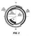
- controller 310may actuate exhaust valve 155 to open for a short time (shown as time period 156 in Figs. 2 and 3 ), starting at the end of the intake stroke, and closing during the compression stroke.
- Exhaust valve 155may start to open near the end of the intake stroke, at approximately BDC, and remain open for about 30 to 70 crank angle degrees after BDC during the first half of the compression stroke before closing.
- piston 106may be compressing the fluid in combustion chamber 124, some air may be forced through opened exhaust valve 155 and into exhaust manifold 150. The air may be pushed into conduit 160. At the end of the compression stroke, after exhaust valve 155 has closed, fuel injector 123 may inject fuel into combustion chamber 124. Fuel injector 123 may inject fuel at the end of the compression stroke, near TDC. Combustion may then occur within combustion chamber 124.
- Controller 310may control the opening/closing time and position of exhaust valve 155 at the end of the intake stroke and the first part of the compression stroke based on engine parameters such as, for example, a speed of engine 110, a load on engine 110, and/or when NOx production exceeds a certain threshold. Controller 310 may control exhaust valve 155 based on engine speed and engine load measurements input to controller 310 via electrical line 350 from sensor 360. Controller 310 may also control exhaust valve 155 based on measurements of NOx emissions input to controller 310 via electrical line 320 from sensor 340.
- the air forced into conduit 160 during the compression (i.e., second) strokemay be directed through turbine 190.
- turbine 190By directing air through turbine 190 during the compression stroke, the efficiency of turbocharger 180 and compressor 200 may be improved.
- the airmay then be forced through conduit 240 and into filter assembly 260. This flow of air may also improve the combustion of soot particulates within filter assembly 260. Exhaust may pass from filter assembly 260 to the atmosphere. It is contemplated that the opening of exhaust valve 155 may be triggered by regeneration requirements, as opposed to requirements for reducing NOx, if desired.
- Emissions reduction system 100may help to reduce NOx emissions while maintaining normal operation of turbocharger 180 and filter assembly 260.
- Exhaust valve 155may be opened during the compression stroke to help reduce the formulation of regulated NOx emissions during the ensuing power stroke. Also, by doing so, the efficiency of turbocharger 180 may be improved. Since the air released through exhaust valve 155 may be directed to filter assembly 260, combustion within filter assembly 260 may be improved. This may cause combustion of soot on the filter media of filter assembly 260, which may promote compliance with emissions standards by extending filter service life.
Landscapes
- Engineering & Computer Science (AREA)
- Chemical & Material Sciences (AREA)
- Combustion & Propulsion (AREA)
- Mechanical Engineering (AREA)
- General Engineering & Computer Science (AREA)
- Physics & Mathematics (AREA)
- Electromagnetism (AREA)
- Processes For Solid Components From Exhaust (AREA)
- Output Control And Ontrol Of Special Type Engine (AREA)
- Supercharger (AREA)
- Control Of Throttle Valves Provided In The Intake System Or In The Exhaust System (AREA)
Abstract
Description
- The present disclosure is directed to an engine system and, more particularly, to an engine system having valve actuated filter regeneration.
- A fuel and air mixture is combusted within cylinders of an internal combustion engine. Reciprocating pistons are moved between top dead center and bottom dead center positions within the cylinders by a crankshaft of the engine. As each piston moves toward its top dead center position, it compresses the fuel and air mixture. When the compressed mixture combusts, it expands and drives the piston downward toward its bottom dead center position. Combustion within the cylinder releases energy and generates combustion products and by-products, most of which are exhausted from the cylinder into an exhaust system of the engine during an exhaust stroke of the piston. The combustion products and by-products are composed of gaseous compounds (e.g., NOx and HC) and solid particulate matter.
- Due to increased attention on the environment, exhaust emission standards have become more stringent, and the amount of gaseous compounds emitted to the atmosphere from an engine may be regulated depending on the type of engine, size of engine, and/or class of engine. One way to reduce the amount of harmful emissions directed to the atmosphere includes reducing the amount of oxygen available for combustion. A reduction in oxygen results in a lower combustion temperature that causes a proportional reduction in NOx generation. In the past, the reduction in oxygen was achieved by delaying the closing of an intake valve at the beginning of a compression stroke of an engine piston. During the ensuing upward stroke of the piston, some of the air drawn into the cylinder during the previous intake stroke was then pushed back out into the intake manifold. Although effective in reducing the amount of oxygen available for combustion, the compressed air being forced back into an intake manifold of the engine interrupted incoming air flow and resulted in a drop in turbocharger efficiency.
- Another method used by engine manufacturers to reduce emissions is to trap exhaust particulates with a filter medium (e.g., metal mesh or porous ceramic) and/or convert the gaseous compound to innocuous constituents. Since excessive accumulation of particulate matter on the filter medium will shorten the service life of a particulate trap and increase engine back pressure, the particulate matter must be periodically removed from the medium. The method of removing particulate matter from a particulate trap is known as regeneration. Regeneration involves burning off excessive accumulations of particulate matter. This burning off of particulates requires air to facilitate combustion. Typically, air is provided to the particulate trap by a dedicated air supply, which may be expensive, complex, and may perform with low reliability.
- One attempt at improving the process of filter regeneration is described in
U.S. Patent No. 6,718,755 (the '755 patent) issued to Brehob on 13 April 2004. The system described by the '755 patent provides for a temperature rise in an exhaust aftertreatment device. During compression, an exhaust valve of the cylinder is opened, releasing an already combined mixture of air and fuel into the exhaust aftertreatment device. The air and fuel mixture contributes to combustion in the aftertreatment device, eliminating particulates in the filter, without the need for a separate dedicated air supply. - Although the system of the '755 patent may improve filter regeneration, its applicability may be limited. That is, it may only be applicable to gasoline or HCCI (homogeneous charge compression ignition) engines having an already combined mixture of air and fuel at the start of the compression stroke. In a standard diesel engine, fuel is not injected or mixed with the air until the end of the compression stroke. As a result, if applied to a diesel engine, the system of the '755 patent would deliver only air to the filter and no regeneration would occur. In addition, because the '755 patent directs both fuel and air to the filter, the engine may experience a loss in power during the regeneration process. The system does nothing to reduce NOx because both air and fuel are being reduced, and not just the air (i.e., the air/fuel ratio is not changing), and NOx reduction requires less air or lower temperature as compared to the fuel during combustion.
WO 2005/003536 discloses an emission control device for a diesel engine which can be retrofitted. In said emission control device, an exhaust valve is opened when the piston approaches a bottom dead center. Exhaust from the exhaust manifold flows backward in the corresponding cylinder, thus providing benefits of exhaust gas recirculation.DE 100 02 483 discloses a device and a method of heating exhaust treatment devices associated with a spark ignition engine. The spark ignition engine comprises variably controllable intake and exhaust valves. The exhaust valve is opened during the compression stroke for a short time. Opening of the exhaust valve is controlled in top modes a) before fuel injection into the combustion chamber (secondary air induction); and b) after fuel injection into the combustion chamber (controlled afterburning of an air/fuel mixture).- The present disclosure is directed to overcoming one or more of the problems set forth above.
- In accordance with the present invention, an engine as set forth in claim 1 and a method as set forth in claim 7 is provided. Preferred embodiments of the invention are claimed in the dependant claims.
- In accordance with one aspect, the present disclosure is directed toward an engine. The engine includes an engine block at least partially forming a combustion chamber, and a piston located to reciprocate within the combustion chamber. The engine also includes an exhaust valve fluidly connected to the combustion chamber, and a filter assembly fluidly connected to the exhaust valve. The engine further includes a controller configured to open the exhaust valve during a portion of an intake stroke of the piston and a portion of a compression stroke of the piston to reduce an amount of air available for combustion during an ensuing power stroke, wherein the exhaust valve opens at the end of the intake stroke and closes during a first half of the compression stroke.
- According to another aspect, the present disclosure is directed toward, a method for controlling engine emissions. The method includes directing air into a cylinder during an intake stroke. The method also includes releasing a portion of the intake air to an aftertreatment device to reduce an amount of air available for combustion within the cylinder, wherein releasing the portion of the intake air occurs at the end of the intake stroke and ends during a first half of the compression stroke.
Fig. 1 is a schematic illustration of an exemplary disclosed engine;Fig. 2 is a diagram of the valve-timing of the disclosed engine; andFig. 3 is a diagram of the valve-timing of the disclosed engine.Fig. 1 illustrates anexemplary engine 110 having anemissions reduction system 100.Engine 110 may be any kind of engine, such as a gasoline engine, a compression ignition diesel engine, or a gaseous fuel-powered engine.Engine 110 may include anintake 130 configured to direct air and/or fuel into a plurality of cylinders 120 (only one shown) ofengine 110, and anexhaust 135 configured to direct combustion by-products fromcylinders 120 to the atmosphere.Engine 110 may be naturally aspirated or may include forced induction via turbocharging or supercharging.Engine 110 may include anengine block 104 that at least partially definescylinders 120.Engine 110 may also include apiston 106 slidably disposed within eachcylinder 120, and acylinder head 122 that caps a top ofcylinder 120. Acombustion chamber 124 may be formed between a top ofpiston 106, walls ofcylinder 120, and a bottom ofcylinder head 122. Acrankshaft 112 may be rotatably supported withinengine block 104 by way of a plurality of journal bearings (not shown). A connectingrod 108 may connect eachpiston 106 tocrankshaft 112 so that a sliding motion ofpiston 106 within eachrespective cylinder 120 results in a rotation ofcrankshaft 112. Afuel injector 123 may be seated withincylinder head 122, serving to inject fuel intocombustion chamber 124. Anoil pan 116 may be connected toengine block 104 to form a cavity known as acrankcase 118 located belowcylinders 120. Lubricant may be provided fromoil pan 116 to engine surfaces to minimize metal-on-metal contact and inhibit damage to the surfaces.Oil pan 116 may serve as a sump for collecting and supplying this lubricant.Intake 130 may include anair filter 202 serving to clean ambient air drawn intoengine 110. Aconduit 204 may connectair filter 202 to acompressor 200, wherecompressor 200 may be driven by aturbine 190 located withinexhaust 135.Compressor 200 may operate to compress ambient air and deliver the compressed air through aconduit 210 tocombustion chamber 124 via anintake manifold 140. The flow of air intocombustion chamber 124 may be regulated by anintake valve 145.Intake valve 145 may be seated withincylinder head 122 and may be any suitable type of valve known in the art such as, for example, a poppet valve actuated by a cam. The delivery of compressed air may help to overcome a natural limitation of combustion engines by reducing an area of low pressure withincylinders 120 created by a downward stroke ofpistons 106. Therefore,compressor 200 may increase the volumetric efficiency withincylinder 120, and this efficiency may allow more fuel to be burned, resulting in a larger power output fromengine 110.Conduit 210 may include a cooler (not shown), if desired. The cooler may serve to cool gases withinconduit 210, and, thereby, increase the density of the gases and the amount of air supplied toengine 110. Additionally, the flow of air throughconduits Exhaust 135 may include anexhaust valve 155, similar tointake valve 145, which may also be seated withincylinder head 122.Exhaust 135 may further include afirst exhaust conduit 160 connecting anexhaust manifold 150 ofengine 110 toturbine 190.Turbine 190 may receive exhaust gases fromengine 110 throughfirst exhaust conduit 160, causingturbine 190 to rotate. As described above, the rotation ofturbine 190 may drivecompressor 200,turbine 190 together withcompressor 200 forming aturbocharger 180.- A
second exhaust conduit 240 may connectturbine 190 to a downstream-locatedfilter assembly 260.Filter assembly 260 may include any suitable filtration media, absorber, reducer, and/or catalytic converter known in the art for reducing the toxicity of emissions fromengine 110. Soot carried by exhaust fromcombustion chamber 124 may collect withinfilter assembly 260 and require periodic regeneration. Regeneration of the filtration media may include combustion of the trapped soot.Filter assembly 260 may also include aheater 265.Heater 265 may be any suitable heater known in the art such as, for example, a fuel-fired or electric heater, serving to raise the temperature withinfilter assembly 260 to promote the combustion of soot. An exhaust outlet may connectfilter assembly 260 to the atmosphere. Emissions reduction system 100 may also include acontroller 310 in communication withengine 110.Controller 310 may be any type of programmable logic controller known in the art for automating machine processes, such as a switch, a process logic controller, or a digital circuit.Controller 310 may be made from any material known in the art for logic control devices, and may include a protective housing of metal, plastic, or another durable material.Controller 310 may also include input/output arrangements that allow it to be connected to sensors (not shown). The sensors may be situated to monitor various engine parameters, such as ignition timing, fuel opening pressure, crankshaft rotation (crank senior) and cam rotation (cam senior), intake manifold temperature/pressure, cylinder pressure, engine temperature, exhaust manifold temperature/pressure, filter assembly temperature, and exhaust back pressure, if desired.Controller 310 may be connected by anelectrical line 330 to anactuator 157 situated to selectively interrupt the cam-driven motion ofexhaust valve 155.Actuator 157 may be any suitable type of actuator known in the art such as, for example, a selectively actuated cam, a hydraulic cylinder actuator, and/or an electromagnetic actuator.Actuator 157 may open, close, or holdstationary exhaust valve 155 in coordination with the movements ofpiston 106, as described below.Controller 310 may serve to control the movement ofexhaust valve 155 based on instructions or algorithms stored in memory, input from sensors, and/or other methods known in the art.Controller 310 may also control the operation of other elements ofemissions reduction system 100, forexample intake valve 145, injection opening pressure and injection timing, and/orturbine 190.- A
sensor 360, configured to measure engine parameters such as, for example, engine speed and engine load, may be associated withengine 110.Sensor 360 may be connected tocontroller 310 byelectrical line 350. Asensor 340 may be configured to measure NOx emissions fromengine 110, and may be associated withexhaust manifold 150.Sensor 340 may be connected tocontroller 310 byelectrical line 320. - The disclosed engine may help to reduce NOx emissions and regenerate
filter assembly 260, while maintaining normal combustion. Additionally, the disclosed engine may reduce emissions while improving the efficiency of an associated turbocharger. Operation ofengine 110 will now be explained. - During operation of
engine 110,pistons 106 may reciprocate withincylinder 120 to produce a rotation ofcrankshaft 112.Piston 106 may generally follow a four-stroke sequence, moving up and down between a bottom dead center (BDC) position and a top dead center (TDC) position.Piston 106 may be at BDC when it is at its lowest position (i.e., closest to crankshaft 112).Piston 106 may be at TDC when it is at its highest position (i.e., farthest from crankshaft 112). The first stroke ofpiston 106 may be an intake stroke, during whichpiston 106 moves downward toward BDC. During this stroke,intake valve 145 may be opened to allow air intocombustion chamber 124. The second stroke of the four-stroke sequence may be a compression stroke, during whichpiston 106 moves upward toward TDC. During this stroke,intake valve 145 andexhaust valve 155 may normally be closed, such that the air drawn intocylinder 120 may be compressed by the movement ofpiston 106. The third stroke ofengine 110 may be a power stroke, during whichpiston 106 is moved downward toward BDC by combusting gases. During this stroke, bothintake valve 145 andexhaust valve 155 may be closed to allow the expanding gases to work againstpiston 106. The fourth and final stroke may be an exhaust stroke during whichpiston 106 moves upward toward TDC. During this stroke,exhaust valve 155 may open to allowpiston 106 to force exhaust out ofcombustion chamber 124. The four-stroke operation ofengine 110 may be continuously repeated. - In some situations (e.g., when a reduction in NOx generation is required), it may be necessary to selectively interrupt the normal sequence of strokes described above. If a reduction in NOx is required,
controller 310 may actuateexhaust valve 155 to open for a short time (shown astime period 156 inFigs. 2 and3 ), starting at the end of the intake stroke, and closing during the compression stroke.Exhaust valve 155 may start to open near the end of the intake stroke, at approximately BDC, and remain open for about 30 to 70 crank angle degrees after BDC during the first half of the compression stroke before closing. By openingexhaust valve 155 during time period 156 (shown inFigs. 2 and air may be forced out ofcombustion chamber 124, thereby reducing a compression ratio ofengine 110. Sincepiston 106 may be compressing the fluid incombustion chamber 124, some air may be forced through openedexhaust valve 155 and intoexhaust manifold 150. The air may be pushed intoconduit 160. At the end of the compression stroke, afterexhaust valve 155 has closed,fuel injector 123 may inject fuel intocombustion chamber 124.Fuel injector 123 may inject fuel at the end of the compression stroke, near TDC. Combustion may then occur withincombustion chamber 124. Controller 310 may control the opening/closing time and position ofexhaust valve 155 at the end of the intake stroke and the first part of the compression stroke based on engine parameters such as, for example, a speed ofengine 110, a load onengine 110, and/or when NOx production exceeds a certain threshold.Controller 310 may controlexhaust valve 155 based on engine speed and engine load measurements input tocontroller 310 viaelectrical line 350 fromsensor 360.Controller 310 may also controlexhaust valve 155 based on measurements of NOx emissions input tocontroller 310 viaelectrical line 320 fromsensor 340.- The air forced into
conduit 160 during the compression (i.e., second) stroke may be directed throughturbine 190. By directing air throughturbine 190 during the compression stroke, the efficiency ofturbocharger 180 andcompressor 200 may be improved. The air may then be forced throughconduit 240 and intofilter assembly 260. This flow of air may also improve the combustion of soot particulates withinfilter assembly 260. Exhaust may pass fromfilter assembly 260 to the atmosphere. It is contemplated that the opening ofexhaust valve 155 may be triggered by regeneration requirements, as opposed to requirements for reducing NOx, if desired. Emissions reduction system 100 may help to reduce NOx emissions while maintaining normal operation ofturbocharger 180 andfilter assembly 260.Exhaust valve 155 may be opened during the compression stroke to help reduce the formulation of regulated NOx emissions during the ensuing power stroke. Also, by doing so, the efficiency ofturbocharger 180 may be improved. Since the air released throughexhaust valve 155 may be directed to filterassembly 260, combustion withinfilter assembly 260 may be improved. This may cause combustion of soot on the filter media offilter assembly 260, which may promote compliance with emissions standards by extending filter service life.- It will be apparent to those skilled in the art that various modifications and variations can be made to the disclosed emissions system. Other embodiments will be apparent to those skilled in the art from consideration of the specification and practice of the disclosed method and apparatus. It is intended that the specification and examples be considered as exemplary only, with a true scope being indicated by the following claims.
Claims (10)
- An engine (110), comprising:an engine block (104) at least partially forming a combustion chamber (124);a piston (106) located to reciprocate within the combustion chamber;an exhaust valve (155) fluidly connected to the combustion chamber;a filter assembly (260) fluidly connected to the exhaust valve; anda controller (310) configured to open the exhaust valve during a portion of an intake stroke of the piston and a portion of a compression stroke of the piston to reduce an amount of air available for combustion during an ensuing power stroke, wherein the exhaust valve opens at the end of the intake stroke and closes duping a first half of the compression stroke.
- The engine of claim 1, further including a heater (265) located to heat the filter assembly, and a turbine (190) fluidly connected between the exhaust valve and the filter assembly.
- The engine of claim 2, wherein the turbine and the filter assembly are configured to receive air from the combustion chamber during the compression stroke.
- The engine of claim 3, wherein the air facilitates combustion of particulate matter within the filter assembly.
- The engine of claim 1, wherein the exhaust valve opens near BDC and closes between 30 degrees and 70 degrees after BDC.
- The engine of claim 5, wherein the fuel injector injects fuel near the end of the compression stroke, near TDC.
- Method for controlling engine emissions in an engine provided with a filter assembly fluidly connected to an exhaust valve and comprising the steps of opening the exhaust valve during a portion of an intake stroke of the piston and a portion of a compression stroke of the piston for releasing intake air and to reduce an amount of air available for combustion during an ensuing power stroke, whereby the exhaust valve is opened after a majority of the intake stroke is complete and closed during a first half of the compression stroke.
- The method of claim 7, wherein the released portion of the intake air facilitates regeneration of the filter device.
- The method of claim 8, wherein releasing the portion of the intake air to the filter device includes passing the portion of the released air through a turbine (190) to improve turbine efficiency.
- The method of claim 9, further including sensing at least one engine parameter, wherein the portion of intake air released to the filter device, varies based on a value of the sensed engine parameter.
Applications Claiming Priority (1)
| Application Number | Priority Date | Filing Date | Title |
|---|---|---|---|
| US12/007,004US20090173062A1 (en) | 2008-01-04 | 2008-01-04 | Engine system having valve actuated filter regeneration |
Publications (2)
| Publication Number | Publication Date |
|---|---|
| EP2077380A1 EP2077380A1 (en) | 2009-07-08 |
| EP2077380B1true EP2077380B1 (en) | 2012-03-21 |
Family
ID=40328850
Family Applications (1)
| Application Number | Title | Priority Date | Filing Date |
|---|---|---|---|
| EP08022097AActiveEP2077380B1 (en) | 2008-01-04 | 2008-12-19 | Engine system having valve actuated particle filter regeneration |
Country Status (3)
| Country | Link |
|---|---|
| US (1) | US20090173062A1 (en) |
| EP (1) | EP2077380B1 (en) |
| AT (1) | ATE550535T1 (en) |
Families Citing this family (5)
| Publication number | Priority date | Publication date | Assignee | Title |
|---|---|---|---|---|
| US9291107B2 (en)* | 2013-03-15 | 2016-03-22 | Paccar Inc | Engine overspeed shutdown systems and methods |
| DE102015110558B4 (en)* | 2015-07-01 | 2022-10-06 | Volkswagen Aktiengesellschaft | internal combustion engine |
| JP6222193B2 (en)* | 2015-09-15 | 2017-11-01 | トヨタ自動車株式会社 | Control device for internal combustion engine |
| US10221779B2 (en) | 2016-12-16 | 2019-03-05 | Ford Global Technologies, Llc | System and method for providing EGR to an engine |
| US10954869B1 (en)* | 2020-02-18 | 2021-03-23 | Ford Global Technologies, Llc | System and method to reduce engine hydrocarbon emissions |
Family Cites Families (28)
| Publication number | Priority date | Publication date | Assignee | Title |
|---|---|---|---|---|
| US4136646A (en)* | 1977-09-30 | 1979-01-30 | Lappa Cleto L | Two cycle rotary internal combustion engine |
| FR2512496A1 (en)* | 1981-09-10 | 1983-03-11 | Semt | METHOD FOR THE AMENAGEMENT OF THE OPERATING CONDITIONS OF AN INTERNAL COMBUSTION ENGINE AND A MOTOR THUS DONE |
| US5205152A (en)* | 1991-02-19 | 1993-04-27 | Caterpillar Inc. | Engine operation and testing using fully flexible valve and injection events |
| JPH05149202A (en)* | 1991-11-13 | 1993-06-15 | Kanesaka Gijutsu Kenkyusho:Kk | Exhaust purification for otto cycle engine |
| JP3347950B2 (en)* | 1996-08-28 | 2002-11-20 | 株式会社ユニシアジェックス | Exhaust valve timing controller |
| JP3116876B2 (en)* | 1997-05-21 | 2000-12-11 | トヨタ自動車株式会社 | Internal combustion engine |
| DE10002483A1 (en)* | 2000-01-21 | 2001-07-26 | Audi Ag | Method for rapid heating of exhaust gas components in IC engines in motor vehicles with one or more exhaust valves per cylinder being opened for short period during compression phase |
| JP2001329830A (en)* | 2000-03-15 | 2001-11-30 | Ibiden Co Ltd | Regeneration device for exhaust gas purifying filter, and filter regeneration method, regeneration program for exhaust gas purifying filter, and recording medium storing program |
| US6519933B2 (en)* | 2000-03-21 | 2003-02-18 | Toyota Jidosha Kabushiki Kaisha | Internal combustion engine having variable valve control system and NOx catalyst |
| DE10064650B4 (en)* | 2000-12-22 | 2016-04-28 | Robert Bosch Gmbh | Electronic method and device of the control of gas exchange valves of an internal combustion engine with variable opening function |
| JP2002349239A (en)* | 2001-05-24 | 2002-12-04 | Isuzu Motors Ltd | Exhaust emission control device for diesel engine |
| US6718755B2 (en)* | 2001-11-02 | 2004-04-13 | Ford Global Technologies, Llc | Method to increase temperature in an exhaust aftertreatment device coupled to a camless engine |
| US6789517B2 (en)* | 2001-11-19 | 2004-09-14 | General Motors Corporation | Method for managing thermal load on an engine |
| JP4093301B2 (en)* | 2002-03-29 | 2008-06-04 | いすゞ自動車株式会社 | Exhaust gas purification system and control method thereof |
| US6826905B2 (en)* | 2002-06-04 | 2004-12-07 | International Engine Intellectual Property Company, Llc | Control strategy for regenerating a particulate filter in an exhaust system of an engine having a variable valve actuation mechanism |
| JP3625456B2 (en)* | 2002-07-16 | 2005-03-02 | 三菱電機株式会社 | Valve timing control device for internal combustion engine |
| US6948310B2 (en)* | 2002-10-01 | 2005-09-27 | Southwest Res Inst | Use of a variable valve actuation system to control the exhaust gas temperature and space velocity of aftertreatment system feedgas |
| JP4159854B2 (en)* | 2002-10-31 | 2008-10-01 | 株式会社日立製作所 | Control device for variable valve timing mechanism |
| DE10259052B3 (en)* | 2002-12-17 | 2004-04-01 | Siemens Ag | Heating method for exhaust catalyzer of direct fuel injection IC engine for automobile using increased exothermy in catalyzer for accelerated heating during cold-starting |
| US6830020B1 (en)* | 2003-05-23 | 2004-12-14 | General Motors Corporation | Diesel engine with intake cam phaser for compression ratio control |
| JP2007002668A (en)* | 2003-07-01 | 2007-01-11 | Tokudaiji Jidosha Bunka Kenkyusho:Kk | Diesel engine exhaust purification device and control means |
| GB2408470B (en)* | 2003-11-25 | 2007-06-13 | Arvin Internat | An internal combustion engine exhaust system |
| JP2005273650A (en)* | 2004-02-26 | 2005-10-06 | Hitachi Ltd | Variable valve control device for internal combustion engine |
| US7167789B1 (en)* | 2005-05-16 | 2007-01-23 | Walt Froloff | Variable compression ratio internal combustion engine |
| EP1811154B1 (en)* | 2004-10-20 | 2013-12-11 | Koichi Hatamura | Engine control method |
| EP1701027B1 (en)* | 2005-03-11 | 2016-12-28 | Ford Global Technologies, Inc. | A method for using partial homogeneous charge compression ignition in a diesel internal combustion engine for NOx trap regeneration |
| US7204227B2 (en)* | 2005-06-15 | 2007-04-17 | Ford Global Technologies, Llc | System and method for reducing NOx emissions in an apparatus having a diesel engine |
| FR2904051A1 (en)* | 2006-07-21 | 2008-01-25 | Renault Sas | METHOD FOR REGENERATING A PARTICLE FILTER |
- 2008
- 2008-01-04USUS12/007,004patent/US20090173062A1/ennot_activeAbandoned
- 2008-12-19EPEP08022097Apatent/EP2077380B1/enactiveActive
- 2008-12-19ATAT08022097Tpatent/ATE550535T1/enactive
Also Published As
| Publication number | Publication date |
|---|---|
| ATE550535T1 (en) | 2012-04-15 |
| US20090173062A1 (en) | 2009-07-09 |
| EP2077380A1 (en) | 2009-07-08 |
Similar Documents
| Publication | Publication Date | Title |
|---|---|---|
| US7472696B2 (en) | Exhaust gas recirculation system with in-cylinder valve actuation | |
| US7201121B2 (en) | Combustion engine including fluidically-driven engine valve actuator | |
| JP4478334B2 (en) | Internal combustion engine having method for controlling combustion process of internal combustion engine and means for controlling engine valve | |
| US7191743B2 (en) | Air and fuel supply system for a combustion engine | |
| CN106285966B (en) | Engine braking method for vehicle retardation | |
| US20120227397A1 (en) | Gaseous fuel-powered engine system having turbo-compounding | |
| US20040103648A1 (en) | Method and apparatus for PM filter regeneration | |
| US20070068149A1 (en) | Air and fuel supply system for combustion engine with particulate trap | |
| US20070062193A1 (en) | Combustion engine including fluidically-controlled engine valve actuator | |
| US20070277779A1 (en) | System for exhaust valve actuation | |
| CN102325976A (en) | Engine control system implementing lean burn 6-stroke cycle | |
| US20140158100A1 (en) | Six-Stroke Engine Exhaust Gas Recirculation System and Method | |
| US8978602B2 (en) | Six-stroke engine power density matching system and method | |
| EP2077380B1 (en) | Engine system having valve actuated particle filter regeneration | |
| US8978603B2 (en) | Six-stroke internal combustion engine valve activation system and method for operating such engine | |
| US7878162B2 (en) | System to control exhaust gas temperature | |
| US20150121853A1 (en) | Engine system for increasing available turbocharger energy | |
| US9057324B2 (en) | Six-stroke engine system with blowdown turbocharger | |
| US8931256B2 (en) | Engine system with passive regeneration of a filter in EGR loop | |
| US9133764B2 (en) | Six-stroke engine system with blowdown exhaust recirculation | |
| US20050241597A1 (en) | Air and fuel supply system for a combustion engine | |
| US20140208742A1 (en) | Engine system with egr over-pressure protection | |
| US20140157758A1 (en) | After-Treatment System and Method for Six-Stroke Combustion Cycle | |
| US8978601B2 (en) | Six-stroke engine system with blowdown exhaust system | |
| JP2009222060A (en) | Exchanging (scavenging) method for combustion gas of two stroke engine |
Legal Events
| Date | Code | Title | Description |
|---|---|---|---|
| PUAI | Public reference made under article 153(3) epc to a published international application that has entered the european phase | Free format text:ORIGINAL CODE: 0009012 | |
| AK | Designated contracting states | Kind code of ref document:A1 Designated state(s):AT BE BG CH CY CZ DE DK EE ES FI FR GB GR HR HU IE IS IT LI LT LU LV MC MT NL NO PL PT RO SE SI SK TR | |
| AX | Request for extension of the european patent | Extension state:AL BA MK RS | |
| 17P | Request for examination filed | Effective date:20091002 | |
| 17Q | First examination report despatched | Effective date:20091102 | |
| AKX | Designation fees paid | Designated state(s):AT BE BG CH CY CZ DE DK EE ES FI FR GB GR HR HU IE IS IT LI LT LU LV MC MT NL NO PL PT RO SE SI SK TR | |
| GRAP | Despatch of communication of intention to grant a patent | Free format text:ORIGINAL CODE: EPIDOSNIGR1 | |
| GRAS | Grant fee paid | Free format text:ORIGINAL CODE: EPIDOSNIGR3 | |
| GRAA | (expected) grant | Free format text:ORIGINAL CODE: 0009210 | |
| AK | Designated contracting states | Kind code of ref document:B1 Designated state(s):AT BE BG CH CY CZ DE DK EE ES FI FR GB GR HR HU IE IS IT LI LT LU LV MC MT NL NO PL PT RO SE SI SK TR | |
| REG | Reference to a national code | Ref country code:GB Ref legal event code:FG4D | |
| REG | Reference to a national code | Ref country code:CH Ref legal event code:EP | |
| REG | Reference to a national code | Ref country code:IE Ref legal event code:FG4D | |
| REG | Reference to a national code | Ref country code:AT Ref legal event code:REF Ref document number:550535 Country of ref document:AT Kind code of ref document:T Effective date:20120415 | |
| REG | Reference to a national code | Ref country code:DE Ref legal event code:R096 Ref document number:602008014216 Country of ref document:DE Effective date:20120516 | |
| REG | Reference to a national code | Ref country code:NL Ref legal event code:VDEP Effective date:20120321 | |
| PG25 | Lapsed in a contracting state [announced via postgrant information from national office to epo] | Ref country code:HR Free format text:LAPSE BECAUSE OF FAILURE TO SUBMIT A TRANSLATION OF THE DESCRIPTION OR TO PAY THE FEE WITHIN THE PRESCRIBED TIME-LIMIT Effective date:20120321 Ref country code:LT Free format text:LAPSE BECAUSE OF FAILURE TO SUBMIT A TRANSLATION OF THE DESCRIPTION OR TO PAY THE FEE WITHIN THE PRESCRIBED TIME-LIMIT Effective date:20120321 Ref country code:NO Free format text:LAPSE BECAUSE OF FAILURE TO SUBMIT A TRANSLATION OF THE DESCRIPTION OR TO PAY THE FEE WITHIN THE PRESCRIBED TIME-LIMIT Effective date:20120621 | |
| LTIE | Lt: invalidation of european patent or patent extension | Effective date:20120321 | |
| PG25 | Lapsed in a contracting state [announced via postgrant information from national office to epo] | Ref country code:FI Free format text:LAPSE BECAUSE OF FAILURE TO SUBMIT A TRANSLATION OF THE DESCRIPTION OR TO PAY THE FEE WITHIN THE PRESCRIBED TIME-LIMIT Effective date:20120321 Ref country code:GR Free format text:LAPSE BECAUSE OF FAILURE TO SUBMIT A TRANSLATION OF THE DESCRIPTION OR TO PAY THE FEE WITHIN THE PRESCRIBED TIME-LIMIT Effective date:20120622 Ref country code:LV Free format text:LAPSE BECAUSE OF FAILURE TO SUBMIT A TRANSLATION OF THE DESCRIPTION OR TO PAY THE FEE WITHIN THE PRESCRIBED TIME-LIMIT Effective date:20120321 | |
| REG | Reference to a national code | Ref country code:AT Ref legal event code:MK05 Ref document number:550535 Country of ref document:AT Kind code of ref document:T Effective date:20120321 | |
| PG25 | Lapsed in a contracting state [announced via postgrant information from national office to epo] | Ref country code:CY Free format text:LAPSE BECAUSE OF FAILURE TO SUBMIT A TRANSLATION OF THE DESCRIPTION OR TO PAY THE FEE WITHIN THE PRESCRIBED TIME-LIMIT Effective date:20120321 | |
| PG25 | Lapsed in a contracting state [announced via postgrant information from national office to epo] | Ref country code:SE Free format text:LAPSE BECAUSE OF FAILURE TO SUBMIT A TRANSLATION OF THE DESCRIPTION OR TO PAY THE FEE WITHIN THE PRESCRIBED TIME-LIMIT Effective date:20120321 Ref country code:PL Free format text:LAPSE BECAUSE OF FAILURE TO SUBMIT A TRANSLATION OF THE DESCRIPTION OR TO PAY THE FEE WITHIN THE PRESCRIBED TIME-LIMIT Effective date:20120321 Ref country code:CZ Free format text:LAPSE BECAUSE OF FAILURE TO SUBMIT A TRANSLATION OF THE DESCRIPTION OR TO PAY THE FEE WITHIN THE PRESCRIBED TIME-LIMIT Effective date:20120321 Ref country code:IS Free format text:LAPSE BECAUSE OF FAILURE TO SUBMIT A TRANSLATION OF THE DESCRIPTION OR TO PAY THE FEE WITHIN THE PRESCRIBED TIME-LIMIT Effective date:20120721 Ref country code:EE Free format text:LAPSE BECAUSE OF FAILURE TO SUBMIT A TRANSLATION OF THE DESCRIPTION OR TO PAY THE FEE WITHIN THE PRESCRIBED TIME-LIMIT Effective date:20120321 Ref country code:SI Free format text:LAPSE BECAUSE OF FAILURE TO SUBMIT A TRANSLATION OF THE DESCRIPTION OR TO PAY THE FEE WITHIN THE PRESCRIBED TIME-LIMIT Effective date:20120321 Ref country code:RO Free format text:LAPSE BECAUSE OF FAILURE TO SUBMIT A TRANSLATION OF THE DESCRIPTION OR TO PAY THE FEE WITHIN THE PRESCRIBED TIME-LIMIT Effective date:20120321 Ref country code:BE Free format text:LAPSE BECAUSE OF FAILURE TO SUBMIT A TRANSLATION OF THE DESCRIPTION OR TO PAY THE FEE WITHIN THE PRESCRIBED TIME-LIMIT Effective date:20120321 | |
| PG25 | Lapsed in a contracting state [announced via postgrant information from national office to epo] | Ref country code:PT Free format text:LAPSE BECAUSE OF FAILURE TO SUBMIT A TRANSLATION OF THE DESCRIPTION OR TO PAY THE FEE WITHIN THE PRESCRIBED TIME-LIMIT Effective date:20120723 Ref country code:SK Free format text:LAPSE BECAUSE OF FAILURE TO SUBMIT A TRANSLATION OF THE DESCRIPTION OR TO PAY THE FEE WITHIN THE PRESCRIBED TIME-LIMIT Effective date:20120321 | |
| PLBE | No opposition filed within time limit | Free format text:ORIGINAL CODE: 0009261 | |
| STAA | Information on the status of an ep patent application or granted ep patent | Free format text:STATUS: NO OPPOSITION FILED WITHIN TIME LIMIT | |
| PG25 | Lapsed in a contracting state [announced via postgrant information from national office to epo] | Ref country code:AT Free format text:LAPSE BECAUSE OF FAILURE TO SUBMIT A TRANSLATION OF THE DESCRIPTION OR TO PAY THE FEE WITHIN THE PRESCRIBED TIME-LIMIT Effective date:20120321 Ref country code:DK Free format text:LAPSE BECAUSE OF FAILURE TO SUBMIT A TRANSLATION OF THE DESCRIPTION OR TO PAY THE FEE WITHIN THE PRESCRIBED TIME-LIMIT Effective date:20120321 Ref country code:NL Free format text:LAPSE BECAUSE OF FAILURE TO SUBMIT A TRANSLATION OF THE DESCRIPTION OR TO PAY THE FEE WITHIN THE PRESCRIBED TIME-LIMIT Effective date:20120321 | |
| 26N | No opposition filed | Effective date:20130102 | |
| PG25 | Lapsed in a contracting state [announced via postgrant information from national office to epo] | Ref country code:IT Free format text:LAPSE BECAUSE OF FAILURE TO SUBMIT A TRANSLATION OF THE DESCRIPTION OR TO PAY THE FEE WITHIN THE PRESCRIBED TIME-LIMIT Effective date:20120321 | |
| REG | Reference to a national code | Ref country code:DE Ref legal event code:R097 Ref document number:602008014216 Country of ref document:DE Effective date:20130102 | |
| PG25 | Lapsed in a contracting state [announced via postgrant information from national office to epo] | Ref country code:ES Free format text:LAPSE BECAUSE OF FAILURE TO SUBMIT A TRANSLATION OF THE DESCRIPTION OR TO PAY THE FEE WITHIN THE PRESCRIBED TIME-LIMIT Effective date:20120702 | |
| PG25 | Lapsed in a contracting state [announced via postgrant information from national office to epo] | Ref country code:MC Free format text:LAPSE BECAUSE OF NON-PAYMENT OF DUE FEES Effective date:20121231 Ref country code:BG Free format text:LAPSE BECAUSE OF FAILURE TO SUBMIT A TRANSLATION OF THE DESCRIPTION OR TO PAY THE FEE WITHIN THE PRESCRIBED TIME-LIMIT Effective date:20120621 | |
| REG | Reference to a national code | Ref country code:CH Ref legal event code:PL | |
| REG | Reference to a national code | Ref country code:IE Ref legal event code:MM4A | |
| REG | Reference to a national code | Ref country code:FR Ref legal event code:ST Effective date:20130830 | |
| PG25 | Lapsed in a contracting state [announced via postgrant information from national office to epo] | Ref country code:CH Free format text:LAPSE BECAUSE OF NON-PAYMENT OF DUE FEES Effective date:20121231 Ref country code:LI Free format text:LAPSE BECAUSE OF NON-PAYMENT OF DUE FEES Effective date:20121231 Ref country code:IE Free format text:LAPSE BECAUSE OF NON-PAYMENT OF DUE FEES Effective date:20121219 | |
| PG25 | Lapsed in a contracting state [announced via postgrant information from national office to epo] | Ref country code:MT Free format text:LAPSE BECAUSE OF FAILURE TO SUBMIT A TRANSLATION OF THE DESCRIPTION OR TO PAY THE FEE WITHIN THE PRESCRIBED TIME-LIMIT Effective date:20120321 Ref country code:FR Free format text:LAPSE BECAUSE OF NON-PAYMENT OF DUE FEES Effective date:20130102 | |
| PG25 | Lapsed in a contracting state [announced via postgrant information from national office to epo] | Ref country code:TR Free format text:LAPSE BECAUSE OF FAILURE TO SUBMIT A TRANSLATION OF THE DESCRIPTION OR TO PAY THE FEE WITHIN THE PRESCRIBED TIME-LIMIT Effective date:20120321 | |
| PG25 | Lapsed in a contracting state [announced via postgrant information from national office to epo] | Ref country code:LU Free format text:LAPSE BECAUSE OF NON-PAYMENT OF DUE FEES Effective date:20121219 | |
| PG25 | Lapsed in a contracting state [announced via postgrant information from national office to epo] | Ref country code:HU Free format text:LAPSE BECAUSE OF FAILURE TO SUBMIT A TRANSLATION OF THE DESCRIPTION OR TO PAY THE FEE WITHIN THE PRESCRIBED TIME-LIMIT Effective date:20081219 | |
| P01 | Opt-out of the competence of the unified patent court (upc) registered | Effective date:20230517 | |
| PGFP | Annual fee paid to national office [announced via postgrant information from national office to epo] | Ref country code:DE Payment date:20241121 Year of fee payment:17 | |
| PGFP | Annual fee paid to national office [announced via postgrant information from national office to epo] | Ref country code:GB Payment date:20241122 Year of fee payment:17 |