EP2076218B1 - Meniscus prosthetic device - Google Patents
Meniscus prosthetic deviceDownload PDFInfo
- Publication number
- EP2076218B1 EP2076218B1EP07853818.8AEP07853818AEP2076218B1EP 2076218 B1EP2076218 B1EP 2076218B1EP 07853818 AEP07853818 AEP 07853818AEP 2076218 B1EP2076218 B1EP 2076218B1
- Authority
- EP
- European Patent Office
- Prior art keywords
- body portion
- prosthetic device
- central body
- fixation member
- fixation
- Prior art date
- Legal status (The legal status is an assumption and is not a legal conclusion. Google has not performed a legal analysis and makes no representation as to the accuracy of the status listed.)
- Not-in-force
Links
- 230000005499meniscusEffects0.000titleclaimsdescription25
- 239000000463materialSubstances0.000claimsdescription45
- 229920002635polyurethanePolymers0.000claimsdescription29
- 239000004814polyurethaneSubstances0.000claimsdescription29
- 210000002303tibiaAnatomy0.000claimsdescription26
- 210000000689upper legAnatomy0.000claimsdescription13
- 210000000988bone and boneAnatomy0.000claimsdescription10
- 239000007943implantSubstances0.000claimsdescription4
- 210000001179synovial fluidAnatomy0.000claimsdescription3
- 125000003118aryl groupChemical group0.000description21
- 229920000642polymerPolymers0.000description20
- 229920001296polysiloxanePolymers0.000description19
- 125000001931aliphatic groupChemical group0.000description18
- 239000004721Polyphenylene oxideSubstances0.000description15
- 238000000034methodMethods0.000description15
- 229920000570polyetherPolymers0.000description14
- 229920002803thermoplastic polyurethanePolymers0.000description13
- 229920005989resinPolymers0.000description11
- 239000011347resinSubstances0.000description11
- 239000004417polycarbonateSubstances0.000description9
- 239000004433Thermoplastic polyurethaneSubstances0.000description8
- 229920000515polycarbonatePolymers0.000description8
- DSUFPYCILZXJFF-UHFFFAOYSA-N4-[[4-[[4-(pentoxycarbonylamino)cyclohexyl]methyl]cyclohexyl]carbamoyloxy]butyl n-[4-[[4-(butoxycarbonylamino)cyclohexyl]methyl]cyclohexyl]carbamateChemical compoundC1CC(NC(=O)OCCCCC)CCC1CC1CCC(NC(=O)OCCCCOC(=O)NC2CCC(CC3CCC(CC3)NC(=O)OCCCC)CC2)CC1DSUFPYCILZXJFF-UHFFFAOYSA-N0.000description6
- 239000000654additiveSubstances0.000description6
- 230000015572biosynthetic processEffects0.000description6
- 238000002513implantationMethods0.000description6
- 238000001746injection mouldingMethods0.000description6
- 238000004519manufacturing processMethods0.000description6
- 210000004353tibial menisciAnatomy0.000description6
- 238000013459approachMethods0.000description5
- 238000000576coating methodMethods0.000description5
- 229920001692polycarbonate urethanePolymers0.000description5
- 230000008569processEffects0.000description5
- 229920002379silicone rubberPolymers0.000description5
- XLYOFNOQVPJJNP-UHFFFAOYSA-NwaterSubstancesOXLYOFNOQVPJJNP-UHFFFAOYSA-N0.000description5
- 229920000049Carbon (fiber)Polymers0.000description4
- 230000008901benefitEffects0.000description4
- 239000012620biological materialSubstances0.000description4
- 239000004917carbon fiberSubstances0.000description4
- 239000011248coating agentSubstances0.000description4
- KPUWHANPEXNPJT-UHFFFAOYSA-NdisiloxaneChemical class[SiH3]O[SiH3]KPUWHANPEXNPJT-UHFFFAOYSA-N0.000description4
- 229920001971elastomerPolymers0.000description4
- 239000000806elastomerSubstances0.000description4
- 238000005516engineering processMethods0.000description4
- 238000001125extrusionMethods0.000description4
- 239000000017hydrogelSubstances0.000description4
- 210000003127kneeAnatomy0.000description4
- 210000000629knee jointAnatomy0.000description4
- 230000033001locomotionEffects0.000description4
- 239000000203mixtureSubstances0.000description4
- 229920001169thermoplasticPolymers0.000description4
- 239000004416thermosoftening plasticSubstances0.000description4
- 239000004970Chain extenderSubstances0.000description3
- 230000000975bioactive effectEffects0.000description3
- 210000000845cartilageAnatomy0.000description3
- 238000000748compression mouldingMethods0.000description3
- 229920001577copolymerPolymers0.000description3
- 230000006378damageEffects0.000description3
- KIQKWYUGPPFMBV-UHFFFAOYSA-NdiisocyanatomethaneChemical compoundO=C=NCN=C=OKIQKWYUGPPFMBV-UHFFFAOYSA-N0.000description3
- 239000004205dimethyl polysiloxaneSubstances0.000description3
- 238000002845discolorationMethods0.000description3
- 238000001727in vivoMethods0.000description3
- 238000010128melt processingMethods0.000description3
- 230000000704physical effectEffects0.000description3
- 229920000435poly(dimethylsiloxane)Polymers0.000description3
- -1polydimethylsiloxanePolymers0.000description3
- 239000000047productSubstances0.000description3
- 239000000126substanceSubstances0.000description3
- 238000003786synthesis reactionMethods0.000description3
- 210000001519tissueAnatomy0.000description3
- VOXZDWNPVJITMN-ZBRFXRBCSA-N17β-estradiolChemical compoundOC1=CC=C2[C@H]3CC[C@](C)([C@H](CC4)O)[C@@H]4[C@@H]3CCC2=C1VOXZDWNPVJITMN-ZBRFXRBCSA-N0.000description2
- BVKZGUZCCUSVTD-UHFFFAOYSA-LCarbonateChemical compound[O-]C([O-])=OBVKZGUZCCUSVTD-UHFFFAOYSA-L0.000description2
- JOYRKODLDBILNP-UHFFFAOYSA-NEthyl urethaneChemical compoundCCOC(N)=OJOYRKODLDBILNP-UHFFFAOYSA-N0.000description2
- LYCAIKOWRPUZTN-UHFFFAOYSA-NEthylene glycolChemical compoundOCCOLYCAIKOWRPUZTN-UHFFFAOYSA-N0.000description2
- 238000005299abrasionMethods0.000description2
- 238000010521absorption reactionMethods0.000description2
- 230000032683agingEffects0.000description2
- 230000004075alterationEffects0.000description2
- 229920005601base polymerPolymers0.000description2
- 230000015556catabolic processEffects0.000description2
- 239000003086colorantSubstances0.000description2
- 238000007334copolymerization reactionMethods0.000description2
- 238000006731degradation reactionMethods0.000description2
- 238000011161developmentMethods0.000description2
- 230000018109developmental processEffects0.000description2
- 230000000694effectsEffects0.000description2
- 238000009472formulationMethods0.000description2
- 230000003301hydrolyzing effectEffects0.000description2
- 230000002209hydrophobic effectEffects0.000description2
- 230000006872improvementEffects0.000description2
- 238000010348incorporationMethods0.000description2
- 238000002347injectionMethods0.000description2
- 239000007924injectionSubstances0.000description2
- 238000003754machiningMethods0.000description2
- 239000012528membraneSubstances0.000description2
- 238000012986modificationMethods0.000description2
- 230000004048modificationEffects0.000description2
- 239000003960organic solventSubstances0.000description2
- 230000001590oxidative effectEffects0.000description2
- 229920000909polytetrahydrofuranPolymers0.000description2
- 230000001737promoting effectEffects0.000description2
- 238000005507sprayingMethods0.000description2
- 230000001954sterilising effectEffects0.000description2
- 238000004659sterilization and disinfectionMethods0.000description2
- 230000035882stressEffects0.000description2
- BDHFUVZGWQCTTF-UHFFFAOYSA-MsulfonateChemical compound[O-]S(=O)=OBDHFUVZGWQCTTF-UHFFFAOYSA-M0.000description2
- 229920002725thermoplastic elastomerPolymers0.000description2
- 229920001187thermosetting polymerPolymers0.000description2
- 150000003673urethanesChemical class0.000description2
- 239000004215Carbon black (E152)Substances0.000description1
- 206010007269CarcinogenicityDiseases0.000description1
- IAYPIBMASNFSPL-UHFFFAOYSA-NEthylene oxideChemical compoundC1CO1IAYPIBMASNFSPL-UHFFFAOYSA-N0.000description1
- 244000043261Hevea brasiliensisSpecies0.000description1
- 229920003171Poly (ethylene oxide)Polymers0.000description1
- 208000027418Wounds and injuryDiseases0.000description1
- 239000002250absorbentSubstances0.000description1
- 238000009825accumulationMethods0.000description1
- 150000007824aliphatic compoundsChemical class0.000description1
- 210000003484anatomyAnatomy0.000description1
- 206010003246arthritisDiseases0.000description1
- 230000001580bacterial effectEffects0.000description1
- 230000004071biological effectEffects0.000description1
- 238000005422blastingMethods0.000description1
- 230000008468bone growthEffects0.000description1
- WERYXYBDKMZEQL-UHFFFAOYSA-Nbutane-1,4-diolChemical groupOCCCCOWERYXYBDKMZEQL-UHFFFAOYSA-N0.000description1
- 230000007670carcinogenicityEffects0.000description1
- 231100000260carcinogenicityToxicity0.000description1
- 125000003636chemical groupChemical group0.000description1
- 239000007795chemical reaction productSubstances0.000description1
- 230000001684chronic effectEffects0.000description1
- 230000000295complement effectEffects0.000description1
- 238000010276constructionMethods0.000description1
- 238000004132cross linkingMethods0.000description1
- 238000005520cutting processMethods0.000description1
- 230000001419dependent effectEffects0.000description1
- 238000013461designMethods0.000description1
- 238000002059diagnostic imagingMethods0.000description1
- 125000005442diisocyanate groupChemical group0.000description1
- 150000002009diolsChemical class0.000description1
- 238000007598dipping methodMethods0.000description1
- 230000001747exhibiting effectEffects0.000description1
- NBVXSUQYWXRMNV-UHFFFAOYSA-NfluoromethaneChemical compoundFCNBVXSUQYWXRMNV-UHFFFAOYSA-N0.000description1
- 230000006870functionEffects0.000description1
- 125000003827glycol groupChemical group0.000description1
- 230000036541healthEffects0.000description1
- 229920001519homopolymerPolymers0.000description1
- 229930195733hydrocarbonNatural products0.000description1
- 150000002430hydrocarbonsChemical class0.000description1
- 125000001183hydrocarbyl groupChemical group0.000description1
- 125000002887hydroxy groupChemical group[H]O*0.000description1
- WGCNASOHLSPBMP-UHFFFAOYSA-NhydroxyacetaldehydeNatural productsOCC=OWGCNASOHLSPBMP-UHFFFAOYSA-N0.000description1
- 238000000338in vitroMethods0.000description1
- 208000014674injuryDiseases0.000description1
- 238000003780insertionMethods0.000description1
- 230000037431insertionEffects0.000description1
- 230000003993interactionEffects0.000description1
- 230000001788irregularEffects0.000description1
- IQPQWNKOIGAROB-UHFFFAOYSA-Nisocyanate groupChemical group[N-]=C=OIQPQWNKOIGAROB-UHFFFAOYSA-N0.000description1
- 239000004816latexSubstances0.000description1
- 229920000126latexPolymers0.000description1
- 230000007774longtermEffects0.000description1
- 230000014759maintenance of locationEffects0.000description1
- 230000013011matingEffects0.000description1
- 230000007246mechanismEffects0.000description1
- 238000002844meltingMethods0.000description1
- 230000008018meltingEffects0.000description1
- 239000002184metalSubstances0.000description1
- VNWKTOKETHGBQD-UHFFFAOYSA-NmethaneChemical compoundCVNWKTOKETHGBQD-UHFFFAOYSA-N0.000description1
- 229920003052natural elastomerPolymers0.000description1
- 229920001194natural rubberPolymers0.000description1
- 230000007935neutral effectEffects0.000description1
- 239000003921oilSubstances0.000description1
- 230000003647oxidationEffects0.000description1
- 238000007254oxidation reactionMethods0.000description1
- 238000010525oxidative degradation reactionMethods0.000description1
- 229920003225polyurethane elastomerPolymers0.000description1
- 229920005749polyurethane resinPolymers0.000description1
- 238000012545processingMethods0.000description1
- 230000002035prolonged effectEffects0.000description1
- 230000035945sensitivityEffects0.000description1
- 238000000926separation methodMethods0.000description1
- 230000035939shockEffects0.000description1
- 239000004945silicone rubberSubstances0.000description1
- 239000007787solidSubstances0.000description1
- 239000000243solutionSubstances0.000description1
- 239000002904solventSubstances0.000description1
- 238000006467substitution reactionMethods0.000description1
- 238000001356surgical procedureMethods0.000description1
- 230000008961swellingEffects0.000description1
- 238000001308synthesis methodMethods0.000description1
- 238000012360testing methodMethods0.000description1
- 230000001225therapeutic effectEffects0.000description1
- 230000008467tissue growthEffects0.000description1
- 230000000699topical effectEffects0.000description1
- 230000007704transitionEffects0.000description1
- 238000013519translationMethods0.000description1
- 230000008733traumaEffects0.000description1
- 238000011282treatmentMethods0.000description1
- 230000002792vascularEffects0.000description1
- 230000002861ventricularEffects0.000description1
- 238000004383yellowingMethods0.000description1
Images


Classifications
- A—HUMAN NECESSITIES
- A61—MEDICAL OR VETERINARY SCIENCE; HYGIENE
- A61F—FILTERS IMPLANTABLE INTO BLOOD VESSELS; PROSTHESES; DEVICES PROVIDING PATENCY TO, OR PREVENTING COLLAPSING OF, TUBULAR STRUCTURES OF THE BODY, e.g. STENTS; ORTHOPAEDIC, NURSING OR CONTRACEPTIVE DEVICES; FOMENTATION; TREATMENT OR PROTECTION OF EYES OR EARS; BANDAGES, DRESSINGS OR ABSORBENT PADS; FIRST-AID KITS
- A61F2/00—Filters implantable into blood vessels; Prostheses, i.e. artificial substitutes or replacements for parts of the body; Appliances for connecting them with the body; Devices providing patency to, or preventing collapsing of, tubular structures of the body, e.g. stents
- A61F2/02—Prostheses implantable into the body
- A61F2/30—Joints
- A61F2/38—Joints for elbows or knees
- A61F2/3872—Meniscus for implantation between the natural bone surfaces
- A—HUMAN NECESSITIES
- A61—MEDICAL OR VETERINARY SCIENCE; HYGIENE
- A61L—METHODS OR APPARATUS FOR STERILISING MATERIALS OR OBJECTS IN GENERAL; DISINFECTION, STERILISATION OR DEODORISATION OF AIR; CHEMICAL ASPECTS OF BANDAGES, DRESSINGS, ABSORBENT PADS OR SURGICAL ARTICLES; MATERIALS FOR BANDAGES, DRESSINGS, ABSORBENT PADS OR SURGICAL ARTICLES
- A61L27/00—Materials for grafts or prostheses or for coating grafts or prostheses
- A61L27/14—Macromolecular materials
- A61L27/18—Macromolecular materials obtained otherwise than by reactions only involving carbon-to-carbon unsaturated bonds
- A—HUMAN NECESSITIES
- A61—MEDICAL OR VETERINARY SCIENCE; HYGIENE
- A61F—FILTERS IMPLANTABLE INTO BLOOD VESSELS; PROSTHESES; DEVICES PROVIDING PATENCY TO, OR PREVENTING COLLAPSING OF, TUBULAR STRUCTURES OF THE BODY, e.g. STENTS; ORTHOPAEDIC, NURSING OR CONTRACEPTIVE DEVICES; FOMENTATION; TREATMENT OR PROTECTION OF EYES OR EARS; BANDAGES, DRESSINGS OR ABSORBENT PADS; FIRST-AID KITS
- A61F2/00—Filters implantable into blood vessels; Prostheses, i.e. artificial substitutes or replacements for parts of the body; Appliances for connecting them with the body; Devices providing patency to, or preventing collapsing of, tubular structures of the body, e.g. stents
- A61F2/02—Prostheses implantable into the body
- A61F2/30—Joints
- A61F2/3094—Designing or manufacturing processes
- A61F2/30942—Designing or manufacturing processes for designing or making customized prostheses, e.g. using templates, CT or NMR scans, finite-element analysis or CAD-CAM techniques
- A—HUMAN NECESSITIES
- A61—MEDICAL OR VETERINARY SCIENCE; HYGIENE
- A61F—FILTERS IMPLANTABLE INTO BLOOD VESSELS; PROSTHESES; DEVICES PROVIDING PATENCY TO, OR PREVENTING COLLAPSING OF, TUBULAR STRUCTURES OF THE BODY, e.g. STENTS; ORTHOPAEDIC, NURSING OR CONTRACEPTIVE DEVICES; FOMENTATION; TREATMENT OR PROTECTION OF EYES OR EARS; BANDAGES, DRESSINGS OR ABSORBENT PADS; FIRST-AID KITS
- A61F2/00—Filters implantable into blood vessels; Prostheses, i.e. artificial substitutes or replacements for parts of the body; Appliances for connecting them with the body; Devices providing patency to, or preventing collapsing of, tubular structures of the body, e.g. stents
- A61F2/02—Prostheses implantable into the body
- A61F2/30—Joints
- A61F2/3094—Designing or manufacturing processes
- A61F2/30965—Reinforcing the prosthesis by embedding particles or fibres during moulding or dipping
- A—HUMAN NECESSITIES
- A61—MEDICAL OR VETERINARY SCIENCE; HYGIENE
- A61F—FILTERS IMPLANTABLE INTO BLOOD VESSELS; PROSTHESES; DEVICES PROVIDING PATENCY TO, OR PREVENTING COLLAPSING OF, TUBULAR STRUCTURES OF THE BODY, e.g. STENTS; ORTHOPAEDIC, NURSING OR CONTRACEPTIVE DEVICES; FOMENTATION; TREATMENT OR PROTECTION OF EYES OR EARS; BANDAGES, DRESSINGS OR ABSORBENT PADS; FIRST-AID KITS
- A61F2/00—Filters implantable into blood vessels; Prostheses, i.e. artificial substitutes or replacements for parts of the body; Appliances for connecting them with the body; Devices providing patency to, or preventing collapsing of, tubular structures of the body, e.g. stents
- A61F2/02—Prostheses implantable into the body
- A61F2/30—Joints
- A61F2002/30001—Additional features of subject-matter classified in A61F2/28, A61F2/30 and subgroups thereof
- A61F2002/30003—Material related properties of the prosthesis or of a coating on the prosthesis
- A61F2002/3006—Properties of materials and coating materials
- A61F2002/30069—Properties of materials and coating materials elastomeric
- A—HUMAN NECESSITIES
- A61—MEDICAL OR VETERINARY SCIENCE; HYGIENE
- A61F—FILTERS IMPLANTABLE INTO BLOOD VESSELS; PROSTHESES; DEVICES PROVIDING PATENCY TO, OR PREVENTING COLLAPSING OF, TUBULAR STRUCTURES OF THE BODY, e.g. STENTS; ORTHOPAEDIC, NURSING OR CONTRACEPTIVE DEVICES; FOMENTATION; TREATMENT OR PROTECTION OF EYES OR EARS; BANDAGES, DRESSINGS OR ABSORBENT PADS; FIRST-AID KITS
- A61F2/00—Filters implantable into blood vessels; Prostheses, i.e. artificial substitutes or replacements for parts of the body; Appliances for connecting them with the body; Devices providing patency to, or preventing collapsing of, tubular structures of the body, e.g. stents
- A61F2/02—Prostheses implantable into the body
- A61F2/30—Joints
- A61F2002/30001—Additional features of subject-matter classified in A61F2/28, A61F2/30 and subgroups thereof
- A61F2002/30667—Features concerning an interaction with the environment or a particular use of the prosthesis
- A61F2002/30673—Lubricating means, e.g. synovial pocket
- A—HUMAN NECESSITIES
- A61—MEDICAL OR VETERINARY SCIENCE; HYGIENE
- A61F—FILTERS IMPLANTABLE INTO BLOOD VESSELS; PROSTHESES; DEVICES PROVIDING PATENCY TO, OR PREVENTING COLLAPSING OF, TUBULAR STRUCTURES OF THE BODY, e.g. STENTS; ORTHOPAEDIC, NURSING OR CONTRACEPTIVE DEVICES; FOMENTATION; TREATMENT OR PROTECTION OF EYES OR EARS; BANDAGES, DRESSINGS OR ABSORBENT PADS; FIRST-AID KITS
- A61F2/00—Filters implantable into blood vessels; Prostheses, i.e. artificial substitutes or replacements for parts of the body; Appliances for connecting them with the body; Devices providing patency to, or preventing collapsing of, tubular structures of the body, e.g. stents
- A61F2/02—Prostheses implantable into the body
- A61F2/30—Joints
- A61F2/30767—Special external or bone-contacting surface, e.g. coating for improving bone ingrowth
- A61F2/30771—Special external or bone-contacting surface, e.g. coating for improving bone ingrowth applied in original prostheses, e.g. holes or grooves
- A61F2002/30878—Special external or bone-contacting surface, e.g. coating for improving bone ingrowth applied in original prostheses, e.g. holes or grooves with non-sharp protrusions, for instance contacting the bone for anchoring, e.g. keels, pegs, pins, posts, shanks, stems, struts
- A61F2002/30884—Fins or wings, e.g. longitudinal wings for preventing rotation within the bone cavity
- A—HUMAN NECESSITIES
- A61—MEDICAL OR VETERINARY SCIENCE; HYGIENE
- A61F—FILTERS IMPLANTABLE INTO BLOOD VESSELS; PROSTHESES; DEVICES PROVIDING PATENCY TO, OR PREVENTING COLLAPSING OF, TUBULAR STRUCTURES OF THE BODY, e.g. STENTS; ORTHOPAEDIC, NURSING OR CONTRACEPTIVE DEVICES; FOMENTATION; TREATMENT OR PROTECTION OF EYES OR EARS; BANDAGES, DRESSINGS OR ABSORBENT PADS; FIRST-AID KITS
- A61F2/00—Filters implantable into blood vessels; Prostheses, i.e. artificial substitutes or replacements for parts of the body; Appliances for connecting them with the body; Devices providing patency to, or preventing collapsing of, tubular structures of the body, e.g. stents
- A61F2/02—Prostheses implantable into the body
- A61F2/30—Joints
- A61F2/38—Joints for elbows or knees
- A61F2002/3895—Joints for elbows or knees unicompartimental
Definitions
- the present disclosuregenerally relates to medical prosthetic devices that replace the functionality of the natural meniscus.
- Each kneehas two menisci, a lateral meniscus and a medial meniscus.
- Each meniscusis a crescent- shaped fibrocartilaginous tissue attached to the tibia at an anterior and a posterior horn. Damage to the meniscus can cause debilitating pain and arthritis.
- the prosthetic devices of the present disclosureare configured to be surgically implanted into a knee joint to replace the natural meniscus.
- WO 2006/036352 A2may be construed to disclose a prosthesis for implantation into a knee joint comportment between a femoral condyle and its corresponding tibial plateau which reduces any excessive prosthesis motion.
- the prosthesisincludes a hard body having a generally elliptical shape in plan and a pair of opposed surfaces including a bottom surface and an opposed top surface, the top surface having a first portion which is generally flat.
- a meniscus prosthesisthat achieves good tribology by maintaining precise contact surfaces between the meniscus, the femoral condyle cartilage, and the tibial plateau cartilage. This is accomplished through the use of a hollow-like structure that is capable of the deformation necessary to accommodate the cartilage surfaces.
- the prosthesiscan advantageously utilize modem material technology in a configuration that, in addition to its outstanding physical characteristics, significantly reduces the need for customization and fitting of the prosthesis during the implantation procedure.
- the meniscus prosthesiscan be manufactured in a sufficient range of sizes to fit all applications.
- the means for mechanical fixation of the implant to the tibial platformmay be integrated into the meniscus body eliminating the requirement for the meniscus to be connected to an intermediary, separate fixation means such as a bone bridge.
- the fixation anchor configurationcan utilize a keyhole cross section geometry that provides secure position control while minimizing lateral stresses that may result from the bone screw securing techniques of prior approaches.
- a meniscus prosthetic devicecomprises a semi-ellipsoidal solid body structure having top and bottom surfaces.
- the top surfaceis concavely shaped to mate with a surgically prepared femoral condyle and the bottom surface is shaped to mate with a surgically prepared tibial plateau.
- the top and bottom surfacesmay define a shelf comprising a membrane section that extends between the interior of the semi-elliptical walls of the body structure.
- the thickness of the membrane sectionmay be less than approximately 2 millimeters and the height of the semi-elliptical walls may be less than approximately 15 millimeters.
- the cross section of the walls of the body structuremay functionally duplicates the nominal cross section of the natural meniscus.
- a fixation anchormay be integrated into and extend from the bottom surface of the prosthetic device.
- the fixation anchorcomprises a keel having a keyhole shaped cross section.
- the anchormay extend substantially parallel to the bottom surface of the prosthetic device.
- the anchormay be in close proximity to the edge of the shelf in some embodiments.
- the keelmay either continuously or discontinuously extend across the width of the bottom surface.
- the fixation anchormay comprise one or more tabs projecting from and perpendicular to the bottom surface.
- the meniscusmay comprise a non-biologically derived material such as a pliable polyurethane based polymer.
- the meniscusmay further include a deformation control element integrated into the meniscus that may, for example, be a filament wound into a machined undercut in the lower surface.
- the bottom surface of the meniscusmay be coated with a bioactive coating applied for the purpose of encouraging the in-growth of natural tissue into the meniscus. Such in-growth may improve fixation of the replacement meniscus to the tibial plateau.
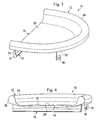
- a prosthetic device 10according to one aspect of the present disclosure.
- Figs. 1, 2 , 3, and 4are various perspective views of the device 10.
- Fig. 5is a cross-sectional view of the device 10.
- the prosthetic device 10is for the replacement of a meniscus that has been damaged, ruptured, disintegrated, diseased, or is otherwise in need of replacement.
- the prosthetic device 10will be described for use with a left knee, lateral meniscus replacement.
- corresponding embodimentsmay be utilized for replacement of any of the other menisci, such as the left knee medial meniscus, right knee lateral meniscus, and/or right knee medial meniscus.
- the position, size, shape, and/or other properties of the fixation anchormay be configured for each particular application.
- the size, shape, thickness, material properties, and/or other properties of the prosthetic devicemay be configured for each particular application.
- the prosthetic meniscus 10comprises an outer body portion 12, a central body portion 14, a fixation member 16, and a fixation device 18.
- the outer body portion 12has an increased thickness and height relative to the central body portion 14. In some instances the outer body portion 12 has a thickness between 5 mm and 15 mm. In some instances, the central body portion 14 has a thickness between .1 mm and 5 mm. In one particular embodiment, the outer body portion 12 has a thickness of approximately 10 mm and the central body portion 14 has a thickness of approximately 2 mm. Further, in some instances the outer body portion 12 has an increased stiffness relative to the central body portion 14. As discussed in greater detail below, this increased stiffness may be a result of different material properties, geometries, support features, and/or other mechanisms for varying the stiffness between the central body portion 14 and the outer body portion 12.
- the central body portion 14defines an upper articulation surface 20 and a lower fixation surface 22.
- the fixation member 16extends from the lower fixation surface 22.
- the upper articulation surface 20is bounded by the outer body portion 12 on several sides.
- the outer body portion 12comprises a rim or wall having an increased height relative to the central body portion 14 such that the central body portion is recessed with respect to the outer body portion.
- the outer body portion 12defines a substantially convex upper surface 24 that tapers down in to the upper articulation surface 20 on one side and to an outer surface 26 of the prosthetic device 10 on the other side.
- the upper surface 20 of the central body portion 14 and the taper of the upper surface 24 of the outer body portion 12define a concave recess configured for receiving a portion of the femur such as the femoral condyle.
- the outer body portion 12has a semi-ellipsoidal shape in some embodiments. In one particular embodiment, the outer body portion 12 is shaped to substantially match the shape of a natural meniscus.
- the boundary 28is a substantially planar surface having a thickness approximately equal to the thickness of the central body portion 14. In other embodiments, the boundary 28 may have an increased thickness relative to the central body portion 14 (e.g., see Figs. 16 and 17 ). In some embodiments, the boundary 28 has a thickness greater than the central body portion 14, but less than the outer body portion 12. In one particular embodiment, the boundary 28 may have a thickness such that it extends above the upper surface 20 approximately one-half of the distance of the upper surface 24 of the outer body portion 12.
- the fixation member 16extends down from the lower surface 22 of the prosthetic device 10.
- the fixation member 16extends from the lower surface 22 adjacent to and substantially parallel to the boundary 28.
- the fixation member 16may extend from other portions of the prosthetic device 10 and/or in other directions, including directions substantially perpendicular to the boundary 28 and/or oblique to the boundary 28.
- Alternative positioning and orientations of the fixation member 16are used to accommodate alternative surgical approaches, patient specific anatomical attributes, meniscus specific orientations, physician preference, and/or other factors.
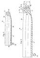
- the fixation member 16comprises a keel structure having a first portion 30 extending directly from the lower surface 22 and a second portion 32 extending from the first portion 30.
- the second portion 32has an increased profile or thickness relative to the first portion 30.
- the fixation member 16has a keyhole cross section that can engage a complementary keyhole shaped groove that has been surgically incised a portion of the tibia, such as the tibia plateau, according to a keyhole surgical approach.
- the fixation member 16is configured to engage an opening extending substantially in a direction from the anterior to the posterior of the tibia.
- the fixation member 16may have other structural geometries to encourage engagement with the tibia.
- the fixation member 16comprises a dovetail configured to engage a dovetailed groove prepared in the tibia.
- the fixation member 16is manufactured as an integral part of the prosthetic device in some embodiments.
- the fixation member 16may be molded simultaneously with the other portions of the prosthetic device 10 and/or permanently attached to the other portions of the prosthetic device.
- Implementing the fixation member 16 as an integral component of the prosthetic device 10provides several distinct advantages. First, the configuration and dimensions of the fixation member 16 are precisely controlled prior to the surgical procedure and may be maintained even for different size prosthetic devices 10. Accordingly, a single size of standardized surgical tools, including bores, rasps and guides, etc., may be employed for the implantation of any size prosthetic device 10.
- the fixation member 16As an integrated section of the overall prosthetic device 10, the possibility of separation of the fixation member 16 from the other portions of the prosthetic device 10 is virtually eliminated.
- the keyhole and/or dovetail configurations of the fixation member 16do not require the use of bone screws or other means to tighten or secure the fixation member 16 to the tibia. Accordingly, the integral fixation member 16 minimizes or eliminates the need to customize the fixation member, thereby reducing the time required to perform the implantation procedure.
- a fixation device 18is utilized in combination with the fixation member 16 to secure the prosthetic device 10 to the tibia. It should be noted, however, that in other embodiments, the fixation member 16 is the sole fixation means utilized to secure the prosthetic device 10 to the tibia.
- the fixation device 18extends from the bottom surface 22. As shown, in some embodiments the fixation device 18 extends substantially perpendicularly to the bottom surface 22.
- the fixation device 18is utilized to provide further fixation of the prosthetic device 10 to the tibia. In that regard, in the current embodiment the fixation device 18 includes an opening 34 for receiving a fixation member.
- the fixation membermay be a bone screw, staple, or other device configured to secure the prosthetic device 2 to the tibia through the opening 102.
- the tab 100may be fastened to the tibia by means of a bone screw extending through the opening and securely engaging the tibia.
- the central body portion 14 bounded by the outer body portion 12serves to isolate the femoral condyle from the tibial plateau when implanted into a patient.
- the outer body portion 12serves to limit the movement of the femoral condyle relative to the prosthetic device.
- the outer body portion 12prevents the portion of the femur movingly engaged with the prosthetic device 10 from moving laterally beyond outer body portion.
- the outer body portion 12limits movement of the femur relative to the prosthetic device 10 in the medial direction.
- the prosthetic device 10provides shock absorption and a desirable tribology between the femur and tibia thereby attributing to the overall therapeutic value of the prosthetic device.
- the prosthetic device 10may be manufactured in various sizes, so that any given application can be satisfied by a "stock" unit. Accordingly, a surgeon could, during an implantation procedure, select a correctly sized device from the selection of stock units. Alternatively, in another embodiment, a replacement meniscus could be custom manufactured for a particular patient utilizing characteristics determined by medical imaging techniques, such as MRI, coupled with computer aided manufacturing (CAM) techniques.
- medical imaging techniquessuch as MRI, coupled with computer aided manufacturing (CAM) techniques.
- the bottom surface 22 of the prosthetic device 10is coated with a bioactive coating to encourage the in-growth of natural tissue to further improve fixation of the prosthetic device to the tibial plateau.
- the coatingis formed by grit blasting or spraying the bottom surface 22.
- the bioactive coatingmay be any suitable material for encouraging tissue growth and, in some embodiment, may be specifically adapted for promoting bone growth between the tibia and the prosthetic device 10.
- the outer body portion 12 of the prosthetic device 10includes a deformation control element to limit the deformation of the outer body portion.
- the deformation control elementmay be a material property, a structural property, an additional component, and/or combinations thereof. It should be noted that the various deformation control elements described herein may be combined to further limit or define the amount of deformation of the outer body portion 12.
- the outer body portion 12is comprised of a reinforced material relative to the central body portion 14.
- the outer body portion 12includes carbon fibers providing additional strength and limiting the flexibility of the outer body portion.
- the carbon fibersare injected prior to the curing of the outer body portion 12.
- the outer body portion 12is formed or molded around the carbon fibers.
- other additivesare utilized to reinforce the material of the outer body portion 12. The particular additives that are used depend upon the material(s) used for forming the outer body portion 12. As shown in Fig.
- the entire outer body portion 12is formed from a substantially uniform materials and/or the additives are equally distributed throughout the outer body portion.
- the deformation control elementmay comprise only a portion of the outer body portion 12. In that regard, the deformation control element may extend along only a portion of the outer body portion 12, the deformation control element may be positioned within a particular portion of the outer body portion, and/or combinations thereof.
- the outer body portion 12includes a wire, cable, or filament 38 extending therethrough.
- the filamentincreases the stiffness of the outer body portion 12 to limit the flexibility and/or deformity.
- the filament 38comprises a carbon fiber.
- the filament 38comprises a metal, polymer, or other material having an increased hardness and/or stiffness relative to the material comprising the central body portion 14.
- the outer body portion 12is formed around the filament 38.
- the filament 38is inserted into the outer body portion 12 prior to curing of the prosthetic device 12.
- the filament 38is inserted into an opening in the body portion 12 and then additional material is inserted into the opening to close the opening and secure the filament therein.
- the filament 38is shown having a substantially circular or cylindrical cross-section.
- the filament 38may have other geometrical cross-sections and/or varying cross-sections along its length.
- the cross-section(s) of the filament 38are configured to provide the desired stiffness and deformation properties to the outer body portion 12.
- the outer body portion 12has a total thickness or height H 1
- the filament 38is positioned a distance H 2 from the peak of the upper surface 24, and the filament has a height H 3 .
- the total thickness H 1 of the outer body portion 12is between 5 mm and 15 mm.
- the thickness H 3 of the filament 38is between and 1 ⁇ 2 of the total thickness H 1 of the outer body portion 12.
- the distance H 2 from the peak of the upper surface 24 to the filament 38varies from 0 (i.e., the filament 38 is positioned at the top of the outer body portion 12) to 3 ⁇ 4 of the total thickness H 1 (i.e., the filament is positioned at the bottom of the outer body portion).
- the filament 38may engaged a recess in the upper surface 24 or the lower surface of the outer body portion 12 configured to receive the filament 38.
- the total thickness H 1is approximately 10 mm
- the distance H 2is approximately 3.3 mm
- the thickness H 3is approximately 3.3 mm.
- the outer body portion 12has a total thickness or width W 1
- the filament 38is positioned a distance W 2 from the outer surface 26, and the filament has a width W 3 .
- the total width W 1 of the outer body portion 12is between 5 mm and 15 mm.
- the width H 3 of the filament 38is between 1 ⁇ 4 and 1 ⁇ 2 of the total width W 1 of the outer body portion 12.
- the distance W 2 from the peak of the upper surface 24 to the filament 38varies from 0 (i.e., the filament 38 is positioned at the very inside of the outer body portion 12) to 3 ⁇ 4 of the total thickness W 1 (i.e., the filament is positioned at the outside of the outer body portion).
- the filament 38may engaged a recess in the outer surface 26 or the inner surface of the outer body portion 12 configured to receive the filament 38.
- the total width W 1is approximately 10 mm
- the distance W 2is approximately 3.3 mm
- the width W 3is approximately 3.3 mm.
- the outer body portion 12may include multiple filaments 38 positioned therein.
- the multiple filaments 38may be spaced equally about the outer body portion 12 and/or grouped into specific areas of the outer body portion.
- the fixation member 16includes a filament 39 extending therethrough.
- the filament 39increases the stiffness of the fixation member 16.
- the filament 39extends substantially along the length of the fixation member 16 through portion 32.
- the fixation member 16may include other features that increase the stiffness of the fixation member.
- the fixation member 16may include features similar to those described with respect to the deformation control elements of the outer body portion 12.
- Fig. 10shown therein is a cross-sectional view of the prosthetic device 10 wherein the outer body portion 12 includes area 40 of increased stiffness and/or hardness.
- the area 40extends substantially across the entire width of the outer body portion 12.
- the area 40may comprise a different material from the rest of the outer body portion, the same material as the rest of the outer body portion with additives, and/or an insert piece configured to be secured within the outer body portion.
- the position, size, and shape of the area 40is configured to achieve the desired deformation properties for the outer body portion 12.
- Fig. 11shown therein is a cross-sectional view of the prosthetic device 10 wherein the outer body portion 12 includes an area 42 of increased stiffness and/or hardness extending substantially along the entire thickness or height of the outer body portion.
- Fig. 12shown therein is a cross-sectional view of the prosthetic device 10 wherein the outer body portion 12 includes a recess 44 for receiving a component 46 for defining the deformation properties of the outer body portion.
- the component 46may be a wire, cable, or filament similar to the filament 38 described above.
- the component 46may be a material that is injected or otherwise introduced into the recess 44 in the outer surface 26.
- the size of the recess 44 and the properties of the component 46are tailored to achieve the desired deformation properties of the outer body portion 12.
- the recess 44comprises between 1/8 and 2/3 of the height of the outer body portion 12 and between 1/8 and 2/3 of the width of the outer body portion.
- the component 46substantially fills the entire recess 44. However, in some embodiments the component 46 is sized such that it fills only a portion of the recess 44. In such embodiments, the remaining portion of the recess 44 may remain vacant or be filled with another material. In some embodiments, the component 46 is secured in the recess 44 by the introduction of additional material into the open space remaining in the recess.
- the outer body portion 12includes an undercut 48 extending upward from the bottom surface of the outer body portion.
- the undercut 48is configured to receive a component 50 for increasing the stiffness and limiting the deformation of the outer body portion 12.
- the component 50may be a wire, cable, or filament similar to the filament 38 described above.
- the component 50may be a material that is injected or otherwise introduced into the recess 48 in the outer surface 26.
- the size of the recess 48 and the properties of the component 50are selected to achieve the desired deformation properties of the outer body portion 12.
- the recess 49comprises between 1/8 and 7/8 of the height of the outer body portion 12 and between 1/8 and 7/8 of the width of the outer body portion.
- the component 50substantially fills the entire recess 48, as shown in Fig. 14 .
- a component 52is sized such that it fills only a portion of the recess 48, as shown in Fig. 15 .
- the remaining portion of the recess 44may remain vacant-as shown in Fig. 15 -or the remaining open portion may be filled with another material or component.
- the component 52is secured in the recess 48 by the introduction of additional material into the open space remaining in the recess.
- a prosthetic device 60shown therein is a prosthetic device 60 according to another embodiment of the present disclosure.
- the prosthetic device 60is substantially similar to the prosthetic device 10 described above. Accordingly, similar reference numerals may be utilized and the description limited for particular aspects of the prosthetic device 60.
- the prosthetic device 60does not include a fixation member 16 or a fixation device 18 as described with respect to the prosthetic device 10. Rather, the prosthetic device 60 is configured to be implanted without rigid fixation to either the femur or tibia.
- the prosthetic device 60may be implanted into a patient without causing permanent damage to the patient's tibia or other bone structure(s) engaged by the prosthetic device. Accordingly, the prosthetic device 60 may be implanted in an attempt to alleviate the patient's knee problems while avoiding permanent destruction of the patient's anatomy, such as cutting or reaming a large opening in the tibia. more invasive procedures.
- the prosthetic device 60includes a boundary 62 extending between the ends of the outer body portion 12 having an increased height relative to the central body portion 14.
- the boundary 62extends substantially above an upper surface 63 of the central body portion 14. Accordingly, the outer body portion 12 and the boundary 62 completely surround the central body portion 14. Accordingly, when positioned between the femur and tibia the outer body portion 12 and the boundary 62 define the outer limits of movement for the femur relative to the prosthetic device 60.
- the boundary 62has a thickness that is between 1 ⁇ 4 and 3 ⁇ 4 the total thickness or height of the outer body portion 12. In one particular embodiment, the boundary 62 has thickness such that it extends above the upper surface 63 approximately one-half of the distance of the upper surface 24 of the outer body portion 12.
- the upper surface 63 and the lower surface 64are both articulating bearing surfaces in the current embodiment.
- the upper and lower surfaces 63, 64are configured to movingly engage with the femur and tibia, respectively.
- the prosthetic device 60can translate and rotate with respect to the femur and/or tibia. Translation is possible in both the anterior-posterior and medial-lateral directions.
- the upper surface 63includes both a vertical and a horizontal bearing component.
- the upper surface 63comprises a concave surface that defines the vertical and horizontal bearing components.
- the lower surface 64includes both a vertical and horizontal bearing component.
- the lower surface 64comprises a convex surface.
- the lower surface 64comprises only a vertical bearing component and is substantially planar.
- the tibiamay be prepared to mate with the substantially planar lower surface.
- the upper surface 63 and/or the lower surface 64are shaped such that the prosthetic device 10 is biased towards a neutral position in the knee.
- the arcuate profiles of the upper surface 63 and/or the lower surface 64are shaped such that the interaction between the surfaces and the bone encourages the bone to a particular orientation relative to the surfaces.
- the prosthetic device 10includes one or more recesses 66 in the upper surface 20 that provide for the accumulation of synovial fluid.
- the recesses 66are positioned at the most prevalent contact points of the femur with the upper surface 20.
- the synovial fluidlubricates the upper articulation surface 20 of the prosthetic device.
- the recesses 66may have various shapes within the upper surface 20.
- the recesses 66may comprise a sloping depression that creates a concave recess in some embodiments.
- the concave recessmay comprises a substantially circular profile, an elongated profile, an irregular shape, and/or combinations thereof.
- the recesses 66are shown as comprising a D-shaped profiles spaced equally about a midline of the prosthetic device 10. However, this depiction is not to be limiting as many shapes, sizes, and transitions may be utilized for the recesses 66. In other embodiments, the prosthetic device 10 includes a greater or fewer number of recesses 66. In some embodiments, the prosthetic device 10 does not include any recesses in the upper surface 20.
- the femoral condylemay be surgically prepared to permit near-normal knee joint flexion after implantation.
- the tibial plateaumay be surgically prepared to fixedly engage with the prosthetic devices.
- Medical grade polyurethane based materialsespecially suitable for use in the embodiments described include, but are not limited to the following:
- Another group of potentially suitable materialsare copolymers of silicone with polyurethanes as exemplified by PurSil.TM., a Silicone Polyether Urethane and CarboSil.TM., a Silicone Polycarbonate Urethane.
- Siliconeshave long been known to be biostable and biocompatible in most implants, and also frequently have the low hardness and low modulus useful for many device applications.
- Conventional silicone elastomerscan have very high ultimate elongations, but only low to moderate tensile strengths. Consequently, the toughness of most biomedical silicone elastomers is not particularly high.
- Another disadvantage of conventional silicone elastomers in device manufacturingis the need for cross-linking to develop useful properties.
- thermoset siliconecannot be redissolved or remelted.
- conventional polyurethance elastomersare generally thermoplastic with excellent physical properties.
- Thermoplastic urethane elastomerscombine high elongation and high tensile strength to form tough, albeit fairly high-modulud elastomers.
- Aromatic polyether TPUscan hiva excellent flex life, tensile strength exceeding 5000 psi, and ultimate elongations greater than 700 percent. They are often used for continuously flexing, chronic implants such as ventricular-assist devices, intraaortic balloons, and artificial heart components. TPUs can easily be processed by melting or dissolving the polymer to fabricate it into useful shapes.
- thermoplastic copolymers containing silicone in the soft segmentinclude PurSil.TM. silicone-polyether-urethane and CarboSil.TM. silicone-polycarbonate-urethane which are true thermoplastic copolymers containing silicone in the soft segment.
- PSXpolydimethylsiloxane
- PTMOpolytetramethyleneoxide
- CarboSilan aliphatic, hydroxyl-terminiated polycarbonate
- the hard segmentconsists of an aromatic diisocyanate, MDI, with low molecular weight glycol chain extender.
- the copolymer chainsare then terminated with silicone (or other) Surface-Modifying End Groups.TM.
- Aliphatic (AL) versions of these materials, with a hard segment synthesized from an aliphatic diisocyanateare also available.
- silicone urethanesdemonstrate previously unavailable combinations of physical properties.
- aromatic silicone polyetherurethaneshave a higher modulus at a given shore hardness than conventional polyether urethanes-the higher the silicone content, the higher the modulus (see PurSil Properties).
- the aliphatic silicone polyetherurethaneshave a very low modulus and a high ultimate elongation typical of silicone homopolymers or even natural rubber (see PurSil AL Properties). This makes them very attractive as high-performance substitutes for conventional cross-linked silicone rubber.
- certain polymershave tensile strengths three to five times higher than conventional silicone biomaterials.
- Suitable materialsinclude Surface Modifying End Groups.TM. (SMEs) which are surface-active oligomers covalently conded to the base polymer during synthesis.
- SMEsSurface Modifying End Groups.TM.
- Ssilicone
- SOsulfonate
- Ffluorocarbon
- Ppolyethylene oxide
- Hhydrocarbon
- SMEsprovide a series of (biomedical) base polymers that can achieve a desired surface chemistry without the use of additives.
- Polyurethanes prepared according to PTG's development processcouple endgroups to the backbone polymer during synthesis via a terminal isocyanate group, not a hard segment.
- the added mobility of endgroups relative to the backboneis though to facilitate the formation of uniform overlayers by the surface-active (end) blocks.
- the use of the surface active endgroupsleaves the original polymer backbone intact so the polymer retains strength and processability.
- the fact that essentially all polymers chains carry the surface-modifying moietyeliminates many of the potential problems associated with additives.
- the SME approachalso allows the incorporation of mixed endgroups into a single polymer.
- the combination of hydrophobic and hydrophilic endgroupsgives the polymers amphipathic characteristics in which the hydrophobic versus hydrophilic balance may be easily controlled.
- ChronoFlex.RTM.polycarbonate aromatic polyurethanes
- family of medical-grade segmented biodurable polyurethane elastomershave been specifically developed by CardioTech International to overcome the in vivo formation of stress-induced microfissures.
- HydroThane.TM.hydrophilic thermoplastic polyurethanes
- HydroThane.TM.is a family of super-absorbent, thermoplastic, polyurethane hydrogels ranging in water content from 5 to 25% by weight.
- HydroThane.TM.is offered as a clear resin in durometer hardness of 80A and 93 Shore A.
- the outstanding characteristic of this family of materialsis the ability to rapidly absorb water, high tensile strength, and high elongation. The result is a polymer having some lubricious characteristics, as well as being inherently bacterial resistant due to their exceptionally high water content at the surface.
- HydroThane.TM. hydrophilic polyurethane resinsare thermoplastic hydrogels, and can be extruded or molded by conventional means. Traditional hydrogels on the other hand are thermosets and difficult to process.
- Tecothante.RTM.aromatic polyether-based polyurethane
- Carbothane.RTM.aliphatic polycarbonate-based polyurethane
- Tecophilic.RTM.high moisture absorption aliphatic polyether-based polyurethane
- Tecoplast.RTM.aromatic polyether-based polyurethane
- Tecothane.RTM.is a family of aromatic, polyether-based TPU's available over a wide range of durometers, colors, and radiopacifiers. One can expect Tecothane resins to exhibit improved solvent resistance and biostability when compared with Tecoflex resins of equal durometers.
- TPUis a family of aliphatic, polycarbonate-based TPU's available over a wide range of durometers, colors and radiopacifiers. This type of TPU has been reported to exhibit excellent oxidative stability, a property which may equate to excellent long-term biostability. This family, like Tecoflex, is easy to process and does not yellow upon aging.
- Tecophilic.RTM.is a family of aliphatic, polyether-based TPU's which have been specially formulated to absorb equilibrium water contents of up to 150% of the weight of dry resin.
- Polyurethanesare designated aromatic or aliphatic on the basis of the chemical nature of the diisocyanate component in the formulation.
- Tecoflex, Tecophilic and Carbothane resinsare manufactured using the aliphatic compound, hydrogenated methylene diisocyanate (HMDI).
- HMDIhydrogenated methylene diisocyanate
- Tecothane and Tecoplast resinsuse the aromatic compound methylene diisocyanate (MDI).
- Tecoflex.RTM.is a family of aliphatic, polyether-based TPU's. These resins are easy to process and do not yellow upon aging. Solution grade versions are candidates to replace latex.
- Aromatic polyurethanesexhibit better resistance to organic solvents and oils than do aliphatics-especially as compared with low durometer (80 to 85 Shore A) aliphatic, where prolonged contact can lead to swelling of the polymer and short-term contact can lead to surface tackiness. While these effects become less noticeable at higher durometers, aromatics exhibit little or no sensitivity upon exposure to the common organic solvents used in the health care industry.
- Tecothane, Tecoplast and Carbothanemelt at temperatures considerably higher than Tecoflex and Tecophilic. Therefore, processing by either extrusion of injection molding puts more heat history into products manufactured from Tecothane, Tecoplast and Carbothane.
- Tecoflex EG-80A and EG-60D resinsmold at nozzle temperatures of approximately 310 degrees F and 340 degrees F respectively while Tecothane and Carbothane products of equivalent durometers mold at nozzle temperatures in the range of 380 degrees F and 435 degrees F.
- Tecogela new member to the Tecophilic family, a hydrogel that can be formulated to absorb equilibrium water contents between 500% to 2000% of the weight of dry resin
- Tecoplast.RTMa family of aromatic, polyether-based TPU's formulated to produce rugged injection molded components exhibiting high durometers and heat deflection temperatures.
- Additional potentially suitable materialsinclude four families of polyurethanes, named Elast-Eon.TM., which are available from AorTech Biomaterials.
- Elast-Eon.TM. 1a Polyhexamethylene oxide (PFMO), aromatic polyurethane, is an improvement on conventional polyurethane in that it has a reduced number of the susceptible chemical groups.
- Elast-Eon.TM.2a Siloxane based macrodiol, aromatic polyurethane, incorporates siloxane unto the soft segment.
- Elast-Eon.TM.4is a modified aromatic hard segment polyurethane.
- Texin 4210 and Texin 4215are thermoplastic polyurethane/polycarbonate blends for injection molding and extrusion.
- Texin 5250, 5286 and 5290are aromatic polyether-based medical grade materials with Shore D hardness of approximately 50, 86, and 90 respectively for injection molding and extrusion. They each comply with 21 CFR 177.1680 and 177.2600.
- the devices described hereinabovemay also be formed by any suitable manufacturing method and may be formed of any suitable medical grade elastomers. It is further appreciated that any of the following manufacturing methods may be utilized: injection molding including inserting inserts, compression molding including inserting inserts, injection-compression molding including inserting inserts, compression molding of prefabricated elements pre-formed by any of the above methods including inserting inserts, spraying including inserting inserts, dipping including inserting inserts, machining from stocks or rods, machining from prefabricated elements including inserting inserts.
Landscapes
- Health & Medical Sciences (AREA)
- Chemical & Material Sciences (AREA)
- Orthopedic Medicine & Surgery (AREA)
- General Health & Medical Sciences (AREA)
- Veterinary Medicine (AREA)
- Oral & Maxillofacial Surgery (AREA)
- Transplantation (AREA)
- Public Health (AREA)
- Life Sciences & Earth Sciences (AREA)
- Animal Behavior & Ethology (AREA)
- Medicinal Chemistry (AREA)
- Chemical Kinetics & Catalysis (AREA)
- Engineering & Computer Science (AREA)
- Physical Education & Sports Medicine (AREA)
- Cardiology (AREA)
- Biomedical Technology (AREA)
- Heart & Thoracic Surgery (AREA)
- Vascular Medicine (AREA)
- Epidemiology (AREA)
- Dermatology (AREA)
- Prostheses (AREA)
- Polymers & Plastics (AREA)
- Organic Chemistry (AREA)
Description
- The present disclosure generally relates to medical prosthetic devices that replace the functionality of the natural meniscus. Each knee has two menisci, a lateral meniscus and a medial meniscus. Each meniscus is a crescent- shaped fibrocartilaginous tissue attached to the tibia at an anterior and a posterior horn. Damage to the meniscus can cause debilitating pain and arthritis. In some instances the prosthetic devices of the present disclosure are configured to be surgically implanted into a knee joint to replace the natural meniscus.
WO 2006/036352 A2 may be construed to disclose a prosthesis for implantation into a knee joint comportment between a femoral condyle and its corresponding tibial plateau which reduces any excessive prosthesis motion. The prosthesis includes a hard body having a generally elliptical shape in plan and a pair of opposed surfaces including a bottom surface and an opposed top surface, the top surface having a first portion which is generally flat.- There is provided a prosthetic device according to the independent claim. Developments are set forth in the dependent claims.
- Preferably, a meniscus prosthesis is disclosed that achieves good tribology by maintaining precise contact surfaces between the meniscus, the femoral condyle cartilage, and the tibial plateau cartilage. This is accomplished through the use of a hollow-like structure that is capable of the deformation necessary to accommodate the cartilage surfaces. The prosthesis can advantageously utilize modem material technology in a configuration that, in addition to its outstanding physical characteristics, significantly reduces the need for customization and fitting of the prosthesis during the implantation procedure. The meniscus prosthesis can be manufactured in a sufficient range of sizes to fit all applications. Preferably, the means for mechanical fixation of the implant to the tibial platform may be integrated into the meniscus body eliminating the requirement for the meniscus to be connected to an intermediary, separate fixation means such as a bone bridge. The fixation anchor configuration can utilize a keyhole cross section geometry that provides secure position control while minimizing lateral stresses that may result from the bone screw securing techniques of prior approaches.
- Preferably, a meniscus prosthetic device comprises a semi-ellipsoidal solid body structure having top and bottom surfaces. The top surface is concavely shaped to mate with a surgically prepared femoral condyle and the bottom surface is shaped to mate with a surgically prepared tibial plateau. The top and bottom surfaces may define a shelf comprising a membrane section that extends between the interior of the semi-elliptical walls of the body structure. The thickness of the membrane section may be less than approximately 2 millimeters and the height of the semi-elliptical walls may be less than approximately 15 millimeters. The cross section of the walls of the body structure may functionally duplicates the nominal cross section of the natural meniscus. A fixation anchor may be integrated into and extend from the bottom surface of the prosthetic device.
- Preferably, the fixation anchor comprises a keel having a keyhole shaped cross section. The anchor may extend substantially parallel to the bottom surface of the prosthetic device. The anchor may be in close proximity to the edge of the shelf in some embodiments. The keel may either continuously or discontinuously extend across the width of the bottom surface. In addition, the fixation anchor may comprise one or more tabs projecting from and perpendicular to the bottom surface. Preferably, the meniscus may comprise a non-biologically derived material such as a pliable polyurethane based polymer. Preferably, the meniscus may further include a deformation control element integrated into the meniscus that may, for example, be a filament wound into a machined undercut in the lower surface. In another embodiment, the bottom surface of the meniscus may be coated with a bioactive coating applied for the purpose of encouraging the in-growth of natural tissue into the meniscus. Such in-growth may improve fixation of the replacement meniscus to the tibial plateau.
- Other features and advantages of the present disclosure will become apparent in the following detailed description of embodiments of the disclosure with reference to the accompanying of drawings, of which:
FIG. 1 is a diagrammatic perspective view of an embodiment of a prosthetic device according to one embodiment of the present disclosure.FIG. 2 is an alternative diagrammatic perspective view of the prosthetic device ofFig. 1 .FIG. 3 is an alternative diagrammatic perspective view of the prosthetic device ofFigs. 1 and 2 .FIG. 4 is an alternative diagrammatic perspective view of the prosthetic device ofFigs. 1, 2 , and3 .FIG. 5 is a diagrammatic cross-sectional view of the prosthetic device ofFigs. 1, 2 ,3, and 4 .FIG. 6 is a diagrammatic side view of an arrangement showing the prosthetic device ofFigs. 1, 2 ,3, and 4 inserted into a surgically prepared knee joint.FIG. 7 is a diagrammatic front view of the arrangement ofFig. 6 .FIG. 8 is a diagrammatic cross-sectional view of a prosthetic device similar toFig. 5 , but showing an alternative embodiment.FIG. 9 is a diagrammatic cross-sectional view of a prosthetic device similar toFigs. 5 and8 , but showing an alternative embodiment.FIG. 10 is a diagrammatic cross-sectional view of a prosthetic device similar toFigs. 5 ,8 , and9 , but showing an alternative embodiment.FIG. 11 is a diagrammatic cross-sectional view of a prosthetic device similar toFigs. 5 ,8 ,9 , and10 but showing an alternative embodiment.FIG. 12 is a diagrammatic cross-sectional view of a prosthetic device similar toFigs. 5 ,8 ,9 ,10, and 11 , but showing an alternative embodiment.FIG. 13 is a diagrammatic cross-sectional view of a prosthetic device similar toFigs. 5 ,8 ,9 ,10 ,11 , and12 but showing an alternative embodiment.FIG. 14 is a diagrammatic cross-sectional view of the prosthetic device ofFig. 13 with an insert according to one embodiment of the present disclosure.FIG. 15 is a diagrammatic cross-sectional view of a prosthetic deviceFig. 13 with an insert similar toFig. 14 , but showing an alternative embodiment of the insert.FIG. 16 is a diagrammatic perspective view of a prosthetic device according to another embodiment of the present disclosure.FIG. 17 is a diagrammatic cross-sectional view of the prosthetic device ofFIG. 16 .FIG. 18 is a diagrammatic perspective view of a prosthetic device according to another embodiment of the present disclosure.- For the purposes of promoting an understanding of the principles of the present disclosure, reference will now be made to the embodiments illustrated in the drawings, and specific language will be used to describe the same. It will nevertheless be understood that no limitation of the scope of the disclosure is intended. Any alterations and further modifications in the described devices, instruments, methods, and any further application of the principles of the disclosure as described herein are contemplated as would normally occur to one skilled in the art to which the disclosure relates. In particular, it is fully contemplated that the features, components, and/or steps described with respect to one embodiment may be combined with the features, components, and/or steps described with respect to other embodiments of the present disclosure.
- Referring now to
Figs. 1, 2 ,3, 4 , and5 shown therein is aprosthetic device 10 according to one aspect of the present disclosure. In particular,Figs. 1, 2 ,3, and 4 are various perspective views of thedevice 10.Fig. 5 is a cross-sectional view of thedevice 10. Generally, theprosthetic device 10 is for the replacement of a meniscus that has been damaged, ruptured, disintegrated, diseased, or is otherwise in need of replacement. For illustrative purposes, theprosthetic device 10 will be described for use with a left knee, lateral meniscus replacement. However, corresponding embodiments may be utilized for replacement of any of the other menisci, such as the left knee medial meniscus, right knee lateral meniscus, and/or right knee medial meniscus. In that regard, the position, size, shape, and/or other properties of the fixation anchor may be configured for each particular application. Similarly, the size, shape, thickness, material properties, and/or other properties of the prosthetic device may be configured for each particular application. - The
prosthetic meniscus 10 comprises anouter body portion 12, acentral body portion 14, afixation member 16, and afixation device 18. Generally, theouter body portion 12 has an increased thickness and height relative to thecentral body portion 14. In some instances theouter body portion 12 has a thickness between 5 mm and 15 mm. In some instances, thecentral body portion 14 has a thickness between .1 mm and 5 mm. In one particular embodiment, theouter body portion 12 has a thickness of approximately 10 mm and thecentral body portion 14 has a thickness of approximately 2 mm. Further, in some instances theouter body portion 12 has an increased stiffness relative to thecentral body portion 14. As discussed in greater detail below, this increased stiffness may be a result of different material properties, geometries, support features, and/or other mechanisms for varying the stiffness between thecentral body portion 14 and theouter body portion 12. - Generally, the
central body portion 14 defines anupper articulation surface 20 and alower fixation surface 22. Thefixation member 16 extends from thelower fixation surface 22. Theupper articulation surface 20 is bounded by theouter body portion 12 on several sides. In that regard, theouter body portion 12 comprises a rim or wall having an increased height relative to thecentral body portion 14 such that the central body portion is recessed with respect to the outer body portion. In the current embodiment, theouter body portion 12 defines a substantially convexupper surface 24 that tapers down in to theupper articulation surface 20 on one side and to anouter surface 26 of theprosthetic device 10 on the other side. Accordingly, theupper surface 20 of thecentral body portion 14 and the taper of theupper surface 24 of theouter body portion 12 define a concave recess configured for receiving a portion of the femur such as the femoral condyle. Theouter body portion 12 has a semi-ellipsoidal shape in some embodiments. In one particular embodiment, theouter body portion 12 is shaped to substantially match the shape of a natural meniscus. - While the majority of the
central body portion 14 is bounded by theouter body portion 12, one side of thebody portion 12 defines an edge orboundary 28. In the current embodiment, theboundary 28 is a substantially planar surface having a thickness approximately equal to the thickness of thecentral body portion 14. In other embodiments, theboundary 28 may have an increased thickness relative to the central body portion 14 (e.g., seeFigs. 16 and17 ). In some embodiments, theboundary 28 has a thickness greater than thecentral body portion 14, but less than theouter body portion 12. In one particular embodiment, theboundary 28 may have a thickness such that it extends above theupper surface 20 approximately one-half of the distance of theupper surface 24 of theouter body portion 12. - As noted above, the
fixation member 16 extends down from thelower surface 22 of theprosthetic device 10. In the current embodiment, thefixation member 16 extends from thelower surface 22 adjacent to and substantially parallel to theboundary 28. In other embodiments, thefixation member 16 may extend from other portions of theprosthetic device 10 and/or in other directions, including directions substantially perpendicular to theboundary 28 and/or oblique to theboundary 28. Alternative positioning and orientations of thefixation member 16 are used to accommodate alternative surgical approaches, patient specific anatomical attributes, meniscus specific orientations, physician preference, and/or other factors. - In the current embodiment, the
fixation member 16 comprises a keel structure having afirst portion 30 extending directly from thelower surface 22 and asecond portion 32 extending from thefirst portion 30. Thesecond portion 32 has an increased profile or thickness relative to thefirst portion 30. In the current embodiment, thefixation member 16 has a keyhole cross section that can engage a complementary keyhole shaped groove that has been surgically incised a portion of the tibia, such as the tibia plateau, according to a keyhole surgical approach. In that regard, thefixation member 16 is configured to engage an opening extending substantially in a direction from the anterior to the posterior of the tibia. In other embodiments, thefixation member 16 may have other structural geometries to encourage engagement with the tibia. In one particular embodiment, thefixation member 16 comprises a dovetail configured to engage a dovetailed groove prepared in the tibia. - The
fixation member 16 is manufactured as an integral part of the prosthetic device in some embodiments. In that regard, thefixation member 16 may be molded simultaneously with the other portions of theprosthetic device 10 and/or permanently attached to the other portions of the prosthetic device. Implementing thefixation member 16 as an integral component of theprosthetic device 10 provides several distinct advantages. First, the configuration and dimensions of thefixation member 16 are precisely controlled prior to the surgical procedure and may be maintained even for different sizeprosthetic devices 10. Accordingly, a single size of standardized surgical tools, including bores, rasps and guides, etc., may be employed for the implantation of any sizeprosthetic device 10. This results in a more precise engagement and mating between theprosthetic device 10 and the tibia, which improves the fixation properties and overall performance of the prosthetic device. Second, by implementing thefixation member 16 as an integrated section of the overallprosthetic device 10, the possibility of separation of thefixation member 16 from the other portions of theprosthetic device 10 is virtually eliminated. Third, the keyhole and/or dovetail configurations of thefixation member 16 do not require the use of bone screws or other means to tighten or secure thefixation member 16 to the tibia. Accordingly, theintegral fixation member 16 minimizes or eliminates the need to customize the fixation member, thereby reducing the time required to perform the implantation procedure. - In some embodiments, a
fixation device 18 is utilized in combination with thefixation member 16 to secure theprosthetic device 10 to the tibia. It should be noted, however, that in other embodiments, thefixation member 16 is the sole fixation means utilized to secure theprosthetic device 10 to the tibia. Thefixation device 18 extends from thebottom surface 22. As shown, in some embodiments thefixation device 18 extends substantially perpendicularly to thebottom surface 22. Thefixation device 18 is utilized to provide further fixation of theprosthetic device 10 to the tibia. In that regard, in the current embodiment thefixation device 18 includes anopening 34 for receiving a fixation member. The fixation member may be a bone screw, staple, or other device configured to secure the prosthetic device 2 to the tibia through the opening 102. In one particular embodiment, the tab 100 may be fastened to the tibia by means of a bone screw extending through the opening and securely engaging the tibia. - When the
prosthetic device 10 is implanted and secured to the tibia, thecentral body portion 14 bounded by theouter body portion 12 serves to isolate the femoral condyle from the tibial plateau when implanted into a patient. In that regard, theouter body portion 12 serves to limit the movement of the femoral condyle relative to the prosthetic device. In particular, in the current embodiment theouter body portion 12 prevents the portion of the femur movingly engaged with theprosthetic device 10 from moving laterally beyond outer body portion. In other embodiments, theouter body portion 12 limits movement of the femur relative to theprosthetic device 10 in the medial direction. Further, theprosthetic device 10 provides shock absorption and a desirable tribology between the femur and tibia thereby attributing to the overall therapeutic value of the prosthetic device. - The
prosthetic device 10 may be manufactured in various sizes, so that any given application can be satisfied by a "stock" unit. Accordingly, a surgeon could, during an implantation procedure, select a correctly sized device from the selection of stock units. Alternatively, in another embodiment, a replacement meniscus could be custom manufactured for a particular patient utilizing characteristics determined by medical imaging techniques, such as MRI, coupled with computer aided manufacturing (CAM) techniques. - In some embodiments, the
bottom surface 22 of theprosthetic device 10 is coated with a bioactive coating to encourage the in-growth of natural tissue to further improve fixation of the prosthetic device to the tibial plateau. In some embodiments, the coating is formed by grit blasting or spraying thebottom surface 22. The bioactive coating may be any suitable material for encouraging tissue growth and, in some embodiment, may be specifically adapted for promoting bone growth between the tibia and theprosthetic device 10. - Referring generally to
Figs. 8-15 , in some embodiments theouter body portion 12 of theprosthetic device 10 includes a deformation control element to limit the deformation of the outer body portion. As will be described in greater detail with respect to the specific embodiments shown inFigs. 8-15 , the deformation control element may be a material property, a structural property, an additional component, and/or combinations thereof. It should be noted that the various deformation control elements described herein may be combined to further limit or define the amount of deformation of theouter body portion 12. - Referring more particularly to
Fig. 8 , shown therein is a cross-sectional view of theprosthetic device 10 wherein theouter body portion 12 is comprised of a reinforced material relative to thecentral body portion 14. For example, in one embodiment theouter body portion 12 includes carbon fibers providing additional strength and limiting the flexibility of the outer body portion. In some embodiments the carbon fibers are injected prior to the curing of theouter body portion 12. In other embodiments, theouter body portion 12 is formed or molded around the carbon fibers. In other embodiments, other additives are utilized to reinforce the material of theouter body portion 12. The particular additives that are used depend upon the material(s) used for forming theouter body portion 12. As shown inFig. 8 , in the current embodiment the entireouter body portion 12 is formed from a substantially uniform materials and/or the additives are equally distributed throughout the outer body portion. However, in other embodiments the deformation control element may comprise only a portion of theouter body portion 12. In that regard, the deformation control element may extend along only a portion of theouter body portion 12, the deformation control element may be positioned within a particular portion of the outer body portion, and/or combinations thereof. - For example, referring more particularly to
Fig. 9 , shown therein is a cross-sectional view of theprosthetic device 10 wherein theouter body portion 12 includes a wire, cable, orfilament 38 extending therethrough. The filament increases the stiffness of theouter body portion 12 to limit the flexibility and/or deformity. In some embodiments, thefilament 38 comprises a carbon fiber. In other embodiments, thefilament 38 comprises a metal, polymer, or other material having an increased hardness and/or stiffness relative to the material comprising thecentral body portion 14. In some embodiments, theouter body portion 12 is formed around thefilament 38. In other embodiments, thefilament 38 is inserted into theouter body portion 12 prior to curing of theprosthetic device 12. In some embodiments, thefilament 38 is inserted into an opening in thebody portion 12 and then additional material is inserted into the opening to close the opening and secure the filament therein. In the current embodiment, thefilament 38 is shown having a substantially circular or cylindrical cross-section. However, in other embodiments thefilament 38 may have other geometrical cross-sections and/or varying cross-sections along its length. The cross-section(s) of thefilament 38 are configured to provide the desired stiffness and deformation properties to theouter body portion 12. - Further in the current embodiment, the
outer body portion 12 has a total thickness or height H1, thefilament 38 is positioned a distance H2 from the peak of theupper surface 24, and the filament has a height H3. In some embodiments, the total thickness H1 of theouter body portion 12 is between 5 mm and 15 mm. In some embodiments, the thickness H3 of thefilament 38 is between and ½ of the total thickness H1 of theouter body portion 12. The distance H2 from the peak of theupper surface 24 to thefilament 38 varies from 0 (i.e., thefilament 38 is positioned at the top of the outer body portion 12) to ¾ of the total thickness H1 (i.e., the filament is positioned at the bottom of the outer body portion). In that regard, in some embodiments thefilament 38 may engaged a recess in theupper surface 24 or the lower surface of theouter body portion 12 configured to receive thefilament 38. In one particular embodiment, the total thickness H1 is approximately 10 mm, the distance H2 is approximately 3.3 mm, and the thickness H3 is approximately 3.3 mm. - Similarly, in the current embodiment the
outer body portion 12 has a total thickness or width W1, thefilament 38 is positioned a distance W2 from theouter surface 26, and the filament has a width W3. In some embodiments, the total width W1 of theouter body portion 12 is between 5 mm and 15 mm. In some embodiments, the width H3 of thefilament 38 is between ¼ and ½ of the total width W1 of theouter body portion 12. The distance W2 from the peak of theupper surface 24 to thefilament 38 varies from 0 (i.e., thefilament 38 is positioned at the very inside of the outer body portion 12) to ¾ of the total thickness W1 (i.e., the filament is positioned at the outside of the outer body portion). In that regard, in some embodiments thefilament 38 may engaged a recess in theouter surface 26 or the inner surface of theouter body portion 12 configured to receive thefilament 38. In one particular embodiment, the total width W1 is approximately 10 mm, the distance W2 is approximately 3.3 mm, and the width W3 is approximately 3.3 mm. In some embodiments, theouter body portion 12 may includemultiple filaments 38 positioned therein. In that regard, themultiple filaments 38 may be spaced equally about theouter body portion 12 and/or grouped into specific areas of the outer body portion. - Further, in the illustrated embodiment the
fixation member 16 includes a filament 39 extending therethrough. The filament 39 increases the stiffness of thefixation member 16. In the current embodiment, the filament 39 extends substantially along the length of thefixation member 16 throughportion 32. In other embodiments, thefixation member 16 may include other features that increase the stiffness of the fixation member. In particular, thefixation member 16 may include features similar to those described with respect to the deformation control elements of theouter body portion 12. - Referring now to
Fig. 10 , shown therein is a cross-sectional view of theprosthetic device 10 wherein theouter body portion 12 includesarea 40 of increased stiffness and/or hardness. In the current embodiment thearea 40 extends substantially across the entire width of theouter body portion 12. Thearea 40 may comprise a different material from the rest of the outer body portion, the same material as the rest of the outer body portion with additives, and/or an insert piece configured to be secured within the outer body portion. As mentioned with respect to the other deformation control elements, the position, size, and shape of thearea 40 is configured to achieve the desired deformation properties for theouter body portion 12. For example, referring toFig. 11 , shown therein is a cross-sectional view of theprosthetic device 10 wherein theouter body portion 12 includes anarea 42 of increased stiffness and/or hardness extending substantially along the entire thickness or height of the outer body portion. - Referring now to
Fig. 12 , shown therein is a cross-sectional view of theprosthetic device 10 wherein theouter body portion 12 includes arecess 44 for receiving acomponent 46 for defining the deformation properties of the outer body portion. For example, in some instances thecomponent 46 may be a wire, cable, or filament similar to thefilament 38 described above. In other instances, thecomponent 46 may be a material that is injected or otherwise introduced into therecess 44 in theouter surface 26. Generally, the size of therecess 44 and the properties of thecomponent 46 are tailored to achieve the desired deformation properties of theouter body portion 12. In some embodiments, therecess 44 comprises between 1/8 and 2/3 of the height of theouter body portion 12 and between 1/8 and 2/3 of the width of the outer body portion. In many embodiments, thecomponent 46 substantially fills theentire recess 44. However, in some embodiments thecomponent 46 is sized such that it fills only a portion of therecess 44. In such embodiments, the remaining portion of therecess 44 may remain vacant or be filled with another material. In some embodiments, thecomponent 46 is secured in therecess 44 by the introduction of additional material into the open space remaining in the recess. - Referring now to
Figs. 13 and 14 , shown therein is a cross-sectional view of theprosthetic device 10 wherein theouter body portion 12 includes an undercut 48 extending upward from the bottom surface of the outer body portion. In some instances the undercut 48 is configured to receive acomponent 50 for increasing the stiffness and limiting the deformation of theouter body portion 12. For example, in some instances thecomponent 50 may be a wire, cable, or filament similar to thefilament 38 described above. In other instances, thecomponent 50 may be a material that is injected or otherwise introduced into therecess 48 in theouter surface 26. Generally, the size of therecess 48 and the properties of thecomponent 50 are selected to achieve the desired deformation properties of theouter body portion 12. In some embodiments, the recess 49 comprises between 1/8 and 7/8 of the height of theouter body portion 12 and between 1/8 and 7/8 of the width of the outer body portion. In many embodiments, thecomponent 50 substantially fills theentire recess 48, as shown inFig. 14 . However, in some embodiments acomponent 52 is sized such that it fills only a portion of therecess 48, as shown inFig. 15 . In such embodiments, the remaining portion of therecess 44 may remain vacant-as shown inFig. 15 -or the remaining open portion may be filled with another material or component. In some embodiments, thecomponent 52 is secured in therecess 48 by the introduction of additional material into the open space remaining in the recess. - Referring now to
Figs. 16 and17 , shown therein is aprosthetic device 60 according to another embodiment of the present disclosure. In some instances, theprosthetic device 60 is substantially similar to theprosthetic device 10 described above. Accordingly, similar reference numerals may be utilized and the description limited for particular aspects of theprosthetic device 60. However, it should be noted that theprosthetic device 60 does not include afixation member 16 or afixation device 18 as described with respect to theprosthetic device 10. Rather, theprosthetic device 60 is configured to be implanted without rigid fixation to either the femur or tibia. In this regard, theprosthetic device 60 may be implanted into a patient without causing permanent damage to the patient's tibia or other bone structure(s) engaged by the prosthetic device. Accordingly, theprosthetic device 60 may be implanted in an attempt to alleviate the patient's knee problems while avoiding permanent destruction of the patient's anatomy, such as cutting or reaming a large opening in the tibia. more invasive procedures. - To this end, the
prosthetic device 60 includes aboundary 62 extending between the ends of theouter body portion 12 having an increased height relative to thecentral body portion 14. In that regard, theboundary 62 extends substantially above anupper surface 63 of thecentral body portion 14. Accordingly, theouter body portion 12 and theboundary 62 completely surround thecentral body portion 14. Accordingly, when positioned between the femur and tibia theouter body portion 12 and theboundary 62 define the outer limits of movement for the femur relative to theprosthetic device 60. That is, the increased height of theouter body portion 12 and theboundary 62 along with the contact pressure on theprosthetic device 60 from being positioned between the femur and the tibia prevents the femur from escaping the cavity defined by theouter body portion 12 and theboundary 62. In some embodiments, theboundary 62 has a thickness that is between ¼ and ¾ the total thickness or height of theouter body portion 12. In one particular embodiment, theboundary 62 has thickness such that it extends above theupper surface 63 approximately one-half of the distance of theupper surface 24 of theouter body portion 12. - Further, the
upper surface 63 and thelower surface 64 are both articulating bearing surfaces in the current embodiment. In particular, the upper andlower surfaces prosthetic device 60 can translate and rotate with respect to the femur and/or tibia. Translation is possible in both the anterior-posterior and medial-lateral directions. In some embodiments, theupper surface 63 includes both a vertical and a horizontal bearing component. To that end, in some embodiments theupper surface 63 comprises a concave surface that defines the vertical and horizontal bearing components. Similarly, in some embodiments thelower surface 64 includes both a vertical and horizontal bearing component. In particular, in some embodiments thelower surface 64 comprises a convex surface. In other embodiments, thelower surface 64 comprises only a vertical bearing component and is substantially planar. In such embodiments, the tibia may be prepared to mate with the substantially planar lower surface. In some embodiments, theupper surface 63 and/or thelower surface 64 are shaped such that theprosthetic device 10 is biased towards a neutral position in the knee. For example, the arcuate profiles of theupper surface 63 and/or thelower surface 64 are shaped such that the interaction between the surfaces and the bone encourages the bone to a particular orientation relative to the surfaces. - Referring to
Fig. 18 , in some embodiments theprosthetic device 10 includes one ormore recesses 66 in theupper surface 20 that provide for the accumulation of synovial fluid. In some embodiments, therecesses 66 are positioned at the most prevalent contact points of the femur with theupper surface 20. In such embodiments, the synovial fluid lubricates theupper articulation surface 20 of the prosthetic device. Therecesses 66 may have various shapes within theupper surface 20. In that regard, therecesses 66 may comprise a sloping depression that creates a concave recess in some embodiments. The concave recess may comprises a substantially circular profile, an elongated profile, an irregular shape, and/or combinations thereof. In the current embodiment, therecesses 66 are shown as comprising a D-shaped profiles spaced equally about a midline of theprosthetic device 10. However, this depiction is not to be limiting as many shapes, sizes, and transitions may be utilized for therecesses 66. In other embodiments, theprosthetic device 10 includes a greater or fewer number ofrecesses 66. In some embodiments, theprosthetic device 10 does not include any recesses in theupper surface 20. - In some instances, the femoral condyle may be surgically prepared to permit near-normal knee joint flexion after implantation. Similarly, the tibial plateau may be surgically prepared to fixedly engage with the prosthetic devices.
- A variety of materials are suitable for use in making the prosthetic meniscus. Medical grade polyurethane based materials especially suitable for use in the embodiments described include, but are not limited to the following:
- Bionate.RTM., manufactured by POLYMER TECHNOLOGY GROUP PTG, a polycarbonate-urethane is among the most extensively tested biomaterials ever developed. Carbonate linkages adjacent to hydrocarbon groups give this family of materials oxidative stability, making these polymers attractive in applications where oxidation is a potential mode of degradation, such as in pacemaker leads, ventricular assist devices, catheters, stents, and many other biomedical devices. Polycarbonate urethanes were the first biomedical polyurethanes promoted for their biostability. Bionate.RTM. polycarbonate-urethane is a thermoplastic elastomer formed as the reaction product of a hydroxyl terminated polycarbonate, an aromatic diisocyanate, and a low molecular weight glycol used as a chain extender. The results of extensive testing encompassing Histology, Carcinogenicity, Biostability, and Tripartite Biocompatibility Guidance for Medical Devices verifies the cost effective material's biocompatibility.
- Another group of potentially suitable materials are copolymers of silicone with polyurethanes as exemplified by PurSil.TM., a Silicone Polyether Urethane and CarboSil.TM., a Silicone Polycarbonate Urethane. Silicones have long been known to be biostable and biocompatible in most implants, and also frequently have the low hardness and low modulus useful for many device applications. Conventional silicone elastomers can have very high ultimate elongations, but only low to moderate tensile strengths. Consequently, the toughness of most biomedical silicone elastomers is not particularly high. Another disadvantage of conventional silicone elastomers in device manufacturing is the need for cross-linking to develop useful properties. Once cross-linked, the resulting thermoset silicone cannot be redissolved or remelted. In contrast, conventional polyurethance elastomers are generally thermoplastic with excellent physical properties. Thermoplastic urethane elastomers (TPUs) combine high elongation and high tensile strength to form tough, albeit fairly high-modulud elastomers. Aromatic polyether TPUs can hiva excellent flex life, tensile strength exceeding 5000 psi, and ultimate elongations greater than 700 percent. They are often used for continuously flexing, chronic implants such as ventricular-assist devices, intraaortic balloons, and artificial heart components. TPUs can easily be processed by melting or dissolving the polymer to fabricate it into useful shapes.
- The prospect of combining the biocompatibility and biostability of conventional silicone elastomers with the processability and toughness of TPUs is an attractive approach to what would appear to be a nearly ideal biomaterial. For instance, it has been reported that silicone acts synergistically with both polycarbonate- and polyether-based polyurethanes to improve in vivo and in vitro stability. In polycarbonate-based polyurethanes, silicone copolymerization has been shown to reduce hydrolytic degradation of the carbonate linkage, whereas in polyether urethanes, the covalently bonded silicone seems to protect the polyether soft segment from oxidative degradation in vivo.
- POLYMER TECHNOLOGY GROUP PTG synthesized and patented silicone-polyurethane copolymers by combining two previously reported methods: copolymerization of silicone (PSX) together with organic (non-silicone) soft segments into the polymer backbone, and the use of surface-modifying end groups to terminate the copolymer chains. Proprietary synthesis methods make high-volume manufacturing possible.
- Other potentially applicable materials include PurSil.TM. silicone-polyether-urethane and CarboSil.TM. silicone-polycarbonate-urethane which are true thermoplastic copolymers containing silicone in the soft segment. These high-strength thermoplastic elastomers are prepared through a multistep bulk synthesis where polydimethylsiloxane (PSX) is incorporated into the polymer soft segment with polytetramethyleneoxide (PTMO) (PurSil) or an aliphatic, hydroxyl-terminiated polycarbonate (CarboSil). The hard segment consists of an aromatic diisocyanate, MDI, with low molecular weight glycol chain extender. The copolymer chains are then terminated with silicone (or other) Surface-Modifying End Groups.TM. Aliphatic (AL) versions of these materials, with a hard segment synthesized from an aliphatic diisocyanate are also available.
- Many of these silicone urethanes demonstrate previously unavailable combinations of physical properties. For example, aromatic silicone polyetherurethanes have a higher modulus at a given shore hardness than conventional polyether urethanes-the higher the silicone content, the higher the modulus (see PurSil Properties). Conversely, the aliphatic silicone polyetherurethanes have a very low modulus and a high ultimate elongation typical of silicone homopolymers or even natural rubber (see PurSil AL Properties). This makes them very attractive as high-performance substitutes for conventional cross-linked silicone rubber. In both the PTMO and PC families, certain polymers have tensile strengths three to five times higher than conventional silicone biomaterials.
- Further examples of suitable materials include Surface Modifying End Groups.TM. (SMEs) which are surface-active oligomers covalently conded to the base polymer during synthesis. SMEs-which include silicone (S), sulfonate (SO), fluorocarbon (F), polyethylene oxide (P), and hydrocarbon (H) groups-control surface chemistry without compromising the bulk properties of the polymer. The result is key surface properties, such as thromboresistance, biostability, and abrasion resistance, are permanently enhanced without additional post-fabrication treatments or topical coatings. This patented technology is applicable to a wide range of PTG's polymers.
- SMEs provide a series of (biomedical) base polymers that can achieve a desired surface chemistry without the use of additives. Polyurethanes prepared according to PTG's development process couple endgroups to the backbone polymer during synthesis via a terminal isocyanate group, not a hard segment. The added mobility of endgroups relative to the backbone is though to facilitate the formation of uniform overlayers by the surface-active (end) blocks. The use of the surface active endgroups leaves the original polymer backbone intact so the polymer retains strength and processability. The fact that essentially all polymers chains carry the surface-modifying moiety eliminates many of the potential problems associated with additives.
- The SME approach also allows the incorporation of mixed endgroups into a single polymer. For example, the combination of hydrophobic and hydrophilic endgroups gives the polymers amphipathic characteristics in which the hydrophobic versus hydrophilic balance may be easily controlled.
- Other suitable materials, manufactured by CARDIOTECH CTE, include ChronoFlex. RTM. And Hydrothane.TM.
- The ChronoFlex.RTM., polycarbonate aromatic polyurethanes, family of medical-grade segmented biodurable polyurethane elastomers have been specifically developed by CardioTech International to overcome the in vivo formation of stress-induced microfissures.
- HydroThane.TM., hydrophilic thermoplastic polyurethanes, is a family of super-absorbent, thermoplastic, polyurethane hydrogels ranging in water content from 5 to 25% by weight. HydroThane.TM. is offered as a clear resin in durometer hardness of 80A and 93 Shore A. The outstanding characteristic of this family of materials is the ability to rapidly absorb water, high tensile strength, and high elongation. The result is a polymer having some lubricious characteristics, as well as being inherently bacterial resistant due to their exceptionally high water content at the surface. HydroThane.TM. hydrophilic polyurethane resins are thermoplastic hydrogels, and can be extruded or molded by conventional means. Traditional hydrogels on the other hand are thermosets and difficult to process.
- Additional suitable materials manufactured by THERMEDICS include Tecothante.RTM. (aromatic polyether-based polyurethane), Carbothane.RTM. (aliphatic polycarbonate-based polyurethane), Tecophilic.RTM. (high moisture absorption aliphatic polyether-based polyurethane) and Tecoplast.RTM. (aromatic polyether-based polyurethane). Tecothane.RTM. is a family of aromatic, polyether-based TPU's available over a wide range of durometers, colors, and radiopacifiers. One can expect Tecothane resins to exhibit improved solvent resistance and biostability when compared with Tecoflex resins of equal durometers. Carbothane.RTM. is a family of aliphatic, polycarbonate-based TPU's available over a wide range of durometers, colors and radiopacifiers. This type of TPU has been reported to exhibit excellent oxidative stability, a property which may equate to excellent long-term biostability. This family, like Tecoflex, is easy to process and does not yellow upon aging. Tecophilic.RTM. is a family of aliphatic, polyether-based TPU's which have been specially formulated to absorb equilibrium water contents of up to 150% of the weight of dry resin.
- Polyurethanes are designated aromatic or aliphatic on the basis of the chemical nature of the diisocyanate component in the formulation. Tecoflex, Tecophilic and Carbothane resins are manufactured using the aliphatic compound, hydrogenated methylene diisocyanate (HMDI). Tecothane and Tecoplast resins use the aromatic compound methylene diisocyanate (MDI). Tecoflex.RTM. is a family of aliphatic, polyether-based TPU's. These resins are easy to process and do not yellow upon aging. Solution grade versions are candidates to replace latex. All formulations, with the exception of Carbothane, are formulated using polytetramethylene ether glycol (PTMEG) and 1,4 butanediol chain extender. Carbothane is specifically formulated with a polycarbonate diol (PCDO). These materials represent the major chemical composition differences among the various families. Aromatic and aliphatic polyurethanes share similar properties that make them outstanding materials for use in medical devices. In general, there is not much difference between medical grade aliphatic and aromatic polyurethanes with regard to the following chemical, mechanical and biological properties: high tensile strength (4,000 to 10,000 psi); high ultimate elongation (250 to 700%); wide range durometer (72 Shore A to 84 Shore D); good biocompatibility; high abrasion resistance; good hydrolytic stability; can be sterilized with ethylene oxide and gamma irradiation; retention of elastomeric properties at low temperature; good melt processing characteristics for extrusion, injection molding, etc.
- With such an impressive array of desirable features, it is no wonder that both aliphatic and aromatic polyurethanes have become increasingly the material of choice in the design of medical grade components. There are, however, distinct differences between these two families of polyurethane that could dictate the selection of one over the other for a particular application:
- In their natural states, both aromatic and aliphatic polyurethanes are clear to very light yellow in color. Aromatics, however, can turn dark yellow to amber as a result of melt processing or sterilization, or even with age. Although the primary objection to the discoloration of aromatic clear tubing or injection molded parts is aesthetic; the yellowing, which is caused by the formation of a chromophore in the NMI portion of the polymer, does not appear to affect other physical properties of the material. Radiopaque grades of Tecothane also exhibit some discoloration during melt processing or sterilization. However, both standard and custom compounded radiopaque grades of Tecothane have been specifically formulated to minimize this discoloration.
- Aromatic polyurethanes exhibit better resistance to organic solvents and oils than do aliphatics-especially as compared with low durometer (80 to 85 Shore A) aliphatic, where prolonged contact can lead to swelling of the polymer and short-term contact can lead to surface tackiness. While these effects become less noticeable at higher durometers, aromatics exhibit little or no sensitivity upon exposure to the common organic solvents used in the health care industry.
- Both aliphatic and aromatic poly-ether based polyuretanes soften considerably within minutes of insertion in the body. Many device manufacturers promote this feature of the urethane products because of patient comfort advantage as well as the reduced risk of vascular trauma. However, this softening effect is less pronounced with aromatic resins than with aliphatic resins.
- Tecothane, Tecoplast and Carbothane melt at temperatures considerably higher than Tecoflex and Tecophilic. Therefore, processing by either extrusion of injection molding puts more heat history into products manufactured from Tecothane, Tecoplast and Carbothane. For example, Tecoflex EG-80A and EG-60D resins mold at nozzle temperatures of approximately 310 degrees F and 340 degrees F respectively while Tecothane and Carbothane products of equivalent durometers mold at nozzle temperatures in the range of 380 degrees F and 435 degrees F.
- Additional materials of interest include Tecogel, a new member to the Tecophilic family, a hydrogel that can be formulated to absorb equilibrium water contents between 500% to 2000% of the weight of dry resin, and Tecoplast.RTM., a family of aromatic, polyether-based TPU's formulated to produce rugged injection molded components exhibiting high durometers and heat deflection temperatures.
- Additional potentially suitable materials include four families of polyurethanes, named Elast-Eon.TM., which are available from AorTech Biomaterials.
- Elast-Eon.TM. 1, a Polyhexamethylene oxide (PFMO), aromatic polyurethane, is an improvement on conventional polyurethane in that it has a reduced number of the susceptible chemical groups. Elast-Eon.TM.2, a Siloxane based macrodiol, aromatic polyurethane, incorporates siloxane unto the soft segment. Elast-Eon.TM.3, a Siloxane based macrodiol, modified hard segment, aromatic polyurethane, is a variation of Elast-Eon.TM.2 with further enhanced flexibility due to incorporation of siloxane into the hard segment. Elast-Eon.TM.4 is a modified aromatic hard segment polyurethane.
- Bayer Corporation also produces candidate materials. Texin 4210 and Texin 4215 are thermoplastic polyurethane/polycarbonate blends for injection molding and extrusion. Texin 5250, 5286 and 5290 are aromatic polyether-based medical grade materials with Shore D hardness of approximately 50, 86, and 90 respectively for injection molding and extrusion. They each comply with 21 CFR 177.1680 and 177.2600.
- It should be appreciated that the devices described hereinabove, while preferably formed by injection molding of polyurethane, may also be formed by any suitable manufacturing method and may be formed of any suitable medical grade elastomers. It is further appreciated that any of the following manufacturing methods may be utilized: injection molding including inserting inserts, compression molding including inserting inserts, injection-compression molding including inserting inserts, compression molding of prefabricated elements pre-formed by any of the above methods including inserting inserts, spraying including inserting inserts, dipping including inserting inserts, machining from stocks or rods, machining from prefabricated elements including inserting inserts.
- The foregoing outlines features of several embodiments so that those skilled in the art may better understand the aspects of the present disclosure. Those skilled in the art should appreciate that they may readily use the present disclosure as a basis for designing or modifying other processes and structures for carrying out the same purposes and/or achieving the same advantages of the embodiments introduced herein. Those skilled in the art should also realize that such constructions do not depart from the scope of the appended claims, and that they may make various changes, substitutions and alterations herein without departing from the scope of the appended claims.
- While the present disclosure has been particularly shown and described with reference to particular embodiments, it will be fully appreciated that variations of the above-disclosed and other features and functions, or alternatives thereof, may be desirably combined into many other different systems or applications. Also that various presently unforeseen or unanticipated alternatives, modifications, variations of improvements therein may be subsequently made by those skilled in the art which are also intended to be encompassed by the following claims.
Claims (16)
- A prosthetic device (10, 60) for placement between a tibial plateau and a femoral condyle, the prosthetic device comprising:a body portion comprising a semi-ellipsoidal outer portion (12) and a central body portion (14), the outer portion having an increased thickness relative to the central body portion, wherein the central body portion has an upper surface (20, 63) configured to articulate engagement with the femoral condyle and a lower surface (22) configured for engagement with the tibial plateau, the upper surface being at least partially concave and the lower surface being at least partially convex;a fixation member (16) extending from and substantially perpendicular to the lower surface of the body portion,whereinthe semi-ellipsoidal outer portion surrounds a majority of the central body portion,the fixation member is configured to engage with a prepared opening in the tibial plateau to fixedly engage the prosthetic device to the tibia,characterised in that a section of the central body portion defines an outer boundary (28, 62) extending between a first end of the semi-ellipsoidal outer portion and a second end of the semi-ellipsoidal outer potion, the outer boundary comprising a substantially planar surface andthe body portion and the fixation member comprise a monolithic structure formed of a resiliently flexible polymeric material.
- The prosthetic device of claim 1, wherein the resiliently flexible polymeric material is a medical grade polyurethane based material.
- The prosthetic device of claim 1, wherein the section of the central body portion has substantially the same thickness as the majority of the central body portion.
- The prosthetic device of claim 1, wherein the section of the central body portion has an increased thickness relative to the majority of the central body portion.
- The prosthetic device of claim 1, wherein the fixation member extends substantially parallel to the outer boundary.
- The prosthetic device of claim 1, further comprising a fixation device (18) configured to further secure the prosthetic device to the tibial plateau.
- The prosthetic device of claim 6, wherein the fixation device includes an opening (34) extending there through configured to receive a bone screw.
- The prosthetic device of claim 1, wherein the fixation member has a keyhole shaped cross section.
- The prosthetic device of claim 1, wherein the fixation member comprises a dove-tail.
- The prosthetic device of claim 1, wherein the upper surface includes at least one recess (66) therein.
- The prosthetic device of claim 10, wherein the at least one recess is positioned at a contact point between the femur and the upper surface, and wherein the at least one recess is configured to receive synovial fluid.
- The prosthetic device of claim 1, wherein the semi-ellipsoidal outer portion comprises a deformation control element.
- The prosthetic device of claim 12, wherein the deformation control element comprises a filament (38) extending within a portion of the semi-ellipsoidal outer portion.
- The prosthetic device of claim 13, wherein the filament is positioned within a recess in the semi-ellipsoidal outer portion.
- The prosthetic device of claim 12, wherein the deformation control element comprises a material having increased stiffness relative to the central body portion.
- The prosthetic device according to claim 1, the device being a meniscus implant comprising:a filament (38) positioned within a portion of the semi-ellipsoidal outer portion such that the outer portion has an increased stiffness relative to the central body portion,the upper surface having at least one recess (66),the fixation member having a key -hole shaped cross-section and the fixation member extending substantially parallel to the outer boundary defined by the central body portion;a fixation device (18) extending from the semi-ellipsoidal outer portion, the fixation device having an opening (34) therein configured to receive a bone fixation member;wherein the body portion, the fixation member, and the fixation device comprise a monolithic structure formed of a polymeric material.
Applications Claiming Priority (2)
| Application Number | Priority Date | Filing Date | Title |
|---|---|---|---|
| US82877006P | 2006-10-09 | 2006-10-09 | |
| PCT/US2007/080625WO2008045807A2 (en) | 2006-10-09 | 2007-10-05 | Meniscus prosthetic device |
Publications (3)
| Publication Number | Publication Date |
|---|---|
| EP2076218A2 EP2076218A2 (en) | 2009-07-08 |
| EP2076218A4 EP2076218A4 (en) | 2012-07-18 |
| EP2076218B1true EP2076218B1 (en) | 2016-03-09 |
Family
ID=39283537
Family Applications (1)
| Application Number | Title | Priority Date | Filing Date |
|---|---|---|---|
| EP07853818.8ANot-in-forceEP2076218B1 (en) | 2006-10-09 | 2007-10-05 | Meniscus prosthetic device |
Country Status (3)
| Country | Link |
|---|---|
| US (4) | US9655730B2 (en) |
| EP (1) | EP2076218B1 (en) |
| WO (1) | WO2008045807A2 (en) |
Families Citing this family (8)
| Publication number | Priority date | Publication date | Assignee | Title |
|---|---|---|---|---|
| WO2013033447A2 (en)* | 2011-09-01 | 2013-03-07 | Grotz R Thomas | Resilient interpositional arthroplasty device |
| US10376370B2 (en) | 2010-09-07 | 2019-08-13 | John Joseph O'Connor | Unicondylar meniscal bearing knee replacement |
| EP3613386A1 (en) | 2014-10-02 | 2020-02-26 | McCullen, Seth | Anatomically designed meniscus implantable devices |
| KR102042646B1 (en)* | 2016-10-06 | 2019-11-08 | 아주대학교산학협력단 | Device for supporting hoop stress of meniscus |
| CA2988052A1 (en)* | 2016-12-06 | 2018-06-06 | Smed-Ta/Td, Llc | Orthopaedic implant with fixation feature and a method of implanting thereof |
| WO2018204440A2 (en) | 2017-05-02 | 2018-11-08 | Mccullen Seth | Composite joint implant |
| EP3400912B1 (en) | 2017-05-10 | 2019-11-20 | Howmedica Osteonics Corporation | Patient specific composite knee replacement |
| CN109620477B (en)* | 2019-02-01 | 2024-04-02 | 北京爱康宜诚医疗器材有限公司 | Meniscal substitute and knee prosthesis having the same |
Family Cites Families (133)
| Publication number | Priority date | Publication date | Assignee | Title |
|---|---|---|---|---|
| US3551560A (en) | 1967-10-02 | 1970-12-29 | Heinrich F Thiele | Process of reconstructing tendons,cartilage,nerve sheaths,and products |
| US3703575A (en) | 1970-12-23 | 1972-11-21 | Heinrich Thiele | Reconstructed cartilaginous tissue and method of implanting it into the human or animal body |
| US4085466A (en) | 1974-11-18 | 1978-04-25 | National Research Development Corporation | Prosthetic joint device |
| DE3160759D1 (en) | 1980-02-21 | 1983-09-22 | Coats Ltd J & P | Device for use in the treatment of damaged articular surfaces of human joints |
| US4344193A (en) | 1980-11-28 | 1982-08-17 | Kenny Charles H | Meniscus prosthesis |
| US4502161A (en)* | 1981-09-21 | 1985-03-05 | Wall W H | Prosthetic meniscus for the repair of joints |
| US4693722A (en) | 1983-08-19 | 1987-09-15 | Wall William H | Prosthetic temporomanibular condyle utilizing a prosthetic meniscus |
| SE450460B (en)* | 1984-11-28 | 1987-06-29 | Albrektsson Bjoern | DEVICE IN ARTIFICIAL MENISH FOR A KNEE JOINT PROTECTION |
| US4936862A (en) | 1986-05-30 | 1990-06-26 | Walker Peter S | Method of designing and manufacturing a human joint prosthesis |
| US5306311A (en) | 1987-07-20 | 1994-04-26 | Regen Corporation | Prosthetic articular cartilage |
| US5681353A (en) | 1987-07-20 | 1997-10-28 | Regen Biologics, Inc. | Meniscal augmentation device |
| US5007934A (en) | 1987-07-20 | 1991-04-16 | Regen Corporation | Prosthetic meniscus |
| US5116374A (en) | 1989-03-02 | 1992-05-26 | Regen Corporation | Prosthetic meniscus |
| US5158574A (en) | 1987-07-20 | 1992-10-27 | Regen Corporation | Prosthetic meniscus |
| US4880429A (en) | 1987-07-20 | 1989-11-14 | Stone Kevin R | Prosthetic meniscus |
| US4919667A (en) | 1988-12-02 | 1990-04-24 | Stryker Corporation | Implant |
| US5092894A (en) | 1990-02-13 | 1992-03-03 | Kenny Charles H | Stabilized meniscus prosthesis |
| US5171322A (en) | 1990-02-13 | 1992-12-15 | Kenny Charles H | Stabilized meniscus prosthesis |
| US5358531A (en)* | 1990-06-12 | 1994-10-25 | British Technology Group Limited | Prosthetic knee joint devices |
| US5344459A (en)* | 1991-12-03 | 1994-09-06 | Swartz Stephen J | Arthroscopically implantable prosthesis |
| US5352463A (en) | 1992-11-13 | 1994-10-04 | Badylak Steven F | Tissue graft for surgical reconstruction of a collagenous meniscus and method therefor |
| US5358525A (en) | 1992-12-28 | 1994-10-25 | Fox John E | Bearing surface for prosthesis and replacement of meniscal cartilage |
| GB9413607D0 (en)* | 1994-07-06 | 1994-08-24 | Goodfellow John W | Endoprosthetic knee joint device |
| US5769899A (en) | 1994-08-12 | 1998-06-23 | Matrix Biotechnologies, Inc. | Cartilage repair unit |
| US5984858A (en) | 1995-06-07 | 1999-11-16 | Crosscart, Inc. | Meniscal xenografts |
| US6046379A (en) | 1995-06-07 | 2000-04-04 | Stone; Kevin R. | Meniscal xenografts |
| US5913900A (en) | 1995-06-07 | 1999-06-22 | Corsscart, Inc. | Substantially native meniscal cartilage heterografts |
| US5865849A (en) | 1995-06-07 | 1999-02-02 | Crosscart, Inc. | Meniscal heterografts |
| US6231608B1 (en) | 1995-06-07 | 2001-05-15 | Crosscart, Inc. | Aldehyde and glycosidase-treated soft and bone tissue xenografts |
| US6049025A (en) | 1995-09-15 | 2000-04-11 | Stone; Kevin R. | Articular cartilage xenografts |
| US5782915A (en) | 1995-09-15 | 1998-07-21 | Stone; Kevin R. | Articular cartilage heterografts |
| US5944755A (en) | 1995-09-15 | 1999-08-31 | Crosscart, Inc. | Articular cartilage xenografts |
| US5788625A (en) | 1996-04-05 | 1998-08-04 | Depuy Orthopaedics, Inc. | Method of making reconstructive SIS structure for cartilaginous elements in situ |
| US6126690A (en) | 1996-07-03 | 2000-10-03 | The Trustees Of Columbia University In The City Of New York | Anatomically correct prosthesis and method and apparatus for manufacturing prosthesis |
| DE29615920U1 (en)* | 1996-09-12 | 1998-01-15 | Waldemar Link GmbH & Co, 22339 Hamburg | Joint endoprosthesis |
| US5871842A (en) | 1996-10-28 | 1999-02-16 | Thomas & Betts International, Inc. | Grafted thermoplastic elastomer barrier layer |
| US20070233269A1 (en) | 2001-05-25 | 2007-10-04 | Conformis, Inc. | Interpositional Joint Implant |
| US6205411B1 (en) | 1997-02-21 | 2001-03-20 | Carnegie Mellon University | Computer-assisted surgery planner and intra-operative guidance system |
| GB9704749D0 (en) | 1997-03-07 | 1997-04-23 | Univ London | Tissue Implant |
| ATE412383T1 (en) | 1997-05-30 | 2008-11-15 | Osteobiologics Inc | FIBER REINFORCED POROUS BIODEGRADABLE IMPLANT DEVICE |
| US6161080A (en) | 1997-11-17 | 2000-12-12 | The Trustees Of Columbia University In The City Of New York | Three dimensional multibody modeling of anatomical joints |
| GB9726820D0 (en) | 1997-12-20 | 1998-02-18 | Smiths Industries Plc | Tubes |
| US6056777A (en) | 1998-02-27 | 2000-05-02 | Mcdowell; Charles L. | Method and device for regenerating cartilage in articulating |
| JP2002505144A (en) | 1998-03-06 | 2002-02-19 | クロスカート インコーポレイテッド | Soft tissue xenograft |
| US6530956B1 (en)* | 1998-09-10 | 2003-03-11 | Kevin A. Mansmann | Resorbable scaffolds to promote cartilage regeneration |
| US6267786B1 (en) | 1999-02-11 | 2001-07-31 | Crosscart, Inc. | Proteoglycan-reduced soft tissue xenografts |
| US7341602B2 (en) | 1999-05-10 | 2008-03-11 | Fell Barry M | Proportioned surgically implantable knee prosthesis |
| US6558421B1 (en) | 2000-09-19 | 2003-05-06 | Barry M. Fell | Surgically implantable knee prosthesis |
| US20050209703A1 (en) | 1999-04-02 | 2005-09-22 | Fell Barry M | Surgically implantable prosthetic system |
| US6206927B1 (en) | 1999-04-02 | 2001-03-27 | Barry M. Fell | Surgically implantable knee prothesis |
| US6966928B2 (en)* | 1999-05-10 | 2005-11-22 | Fell Barry M | Surgically implantable knee prosthesis having keels |
| US6911044B2 (en)* | 1999-05-10 | 2005-06-28 | Barry M. Fell | Surgically implantable knee prosthesis having medially shifted tibial surface |
| US20050033424A1 (en)* | 1999-05-10 | 2005-02-10 | Fell Barry M. | Surgically implantable knee prosthesis |
| US6866684B2 (en)* | 1999-05-10 | 2005-03-15 | Barry M. Fell | Surgically implantable knee prosthesis having different tibial and femoral surface profiles |
| US7297161B2 (en) | 1999-05-10 | 2007-11-20 | Fell Barry M | Surgically implantable knee prosthesis |
| US6923831B2 (en)* | 1999-05-10 | 2005-08-02 | Barry M. Fell | Surgically implantable knee prosthesis having attachment apertures |
| US6893463B2 (en)* | 1999-05-10 | 2005-05-17 | Barry M. Fell | Surgically implantable knee prosthesis having two-piece keyed components |
| US7491235B2 (en)* | 1999-05-10 | 2009-02-17 | Fell Barry M | Surgically implantable knee prosthesis |
| US6251143B1 (en) | 1999-06-04 | 2001-06-26 | Depuy Orthopaedics, Inc. | Cartilage repair unit |
| US6554866B1 (en)* | 1999-10-29 | 2003-04-29 | Sulzer Orthopedics Ltd. | Mono-condylar knee joint prosthesis |
| US6371958B1 (en) | 2000-03-02 | 2002-04-16 | Ethicon, Inc. | Scaffold fixation device for use in articular cartilage repair |
| US6629997B2 (en) | 2000-03-27 | 2003-10-07 | Kevin A. Mansmann | Meniscus-type implant with hydrogel surface reinforced by three-dimensional mesh |
| DE60139262D1 (en) | 2000-08-28 | 2009-08-27 | Disc Dynamics Inc | SYSTEM FOR RECONSTRUCTING JOINT SURFACES OF MAMMALS |
| US6679914B1 (en) | 2000-11-14 | 2004-01-20 | Shlomo Gabbay | Implantable orthopedic support apparatus |
| CA2365376C (en) | 2000-12-21 | 2006-03-28 | Ethicon, Inc. | Use of reinforced foam implants with enhanced integrity for soft tissue repair and regeneration |
| US6852330B2 (en) | 2000-12-21 | 2005-02-08 | Depuy Mitek, Inc. | Reinforced foam implants with enhanced integrity for soft tissue repair and regeneration |
| US20020127265A1 (en) | 2000-12-21 | 2002-09-12 | Bowman Steven M. | Use of reinforced foam implants with enhanced integrity for soft tissue repair and regeneration |
| US6743232B2 (en) | 2001-02-26 | 2004-06-01 | David W. Overaker | Tissue scaffold anchor for cartilage repair |
| US6575986B2 (en) | 2001-02-26 | 2003-06-10 | Ethicon, Inc. | Scaffold fixation device for use in articular cartilage repair |
| US6699252B2 (en) | 2001-04-17 | 2004-03-02 | Regeneration Technologies, Inc. | Methods and instruments for improved meniscus transplantation |
| DE10130485C2 (en) | 2001-06-25 | 2003-06-26 | Robert Riener | Programmable joint simulator |
| US6626950B2 (en) | 2001-06-28 | 2003-09-30 | Ethicon, Inc. | Composite scaffold with post anchor for the repair and regeneration of tissue |
| US20030013975A1 (en) | 2001-07-12 | 2003-01-16 | Kiani Massi E. | Method of selling a continuous mode blood pressure monitor |
| US20050027307A1 (en) | 2001-07-16 | 2005-02-03 | Schwartz Herbert Eugene | Unitary surgical device and method |
| WO2003007786A2 (en) | 2001-07-16 | 2003-01-30 | Depuy Products, Inc. | Porous delivery scaffold and method |
| US7353153B2 (en) | 2001-10-17 | 2008-04-01 | Maria-Grazia Ascenzi | Method and system for modeling bone structure |
| KR100903761B1 (en) | 2001-11-27 | 2009-06-19 | 타키론 가부시기가이샤 | Implant Materials and Manufacturing Method Thereof |
| US7572295B2 (en) | 2001-12-04 | 2009-08-11 | Active Implants Corporation | Cushion bearing implants for load bearing applications |
| JP4324478B2 (en)* | 2002-01-22 | 2009-09-02 | アドバンスト バイオ サーフェイシズ,インコーポレイティド | Interposition arthroplasty system |
| DE10220591B4 (en)* | 2002-05-08 | 2004-03-18 | Mathys Medizinaltechnik Ag | Joint prosthesis with an intermediate element with different radii of curvature |
| US6989034B2 (en) | 2002-05-31 | 2006-01-24 | Ethicon, Inc. | Attachment of absorbable tissue scaffolds to fixation devices |
| WO2003105737A1 (en) | 2002-06-14 | 2003-12-24 | Crosscart, Inc. | Galactosidase-treated prosthetic devices |
| US20040006393A1 (en) | 2002-07-03 | 2004-01-08 | Brian Burkinshaw | Implantable prosthetic knee for lateral compartment |
| ES2309350T3 (en) | 2002-07-11 | 2008-12-16 | Advanced Bio Surfaces, Inc. | METHOD AND EQUIPMENT FOR INTERPOSITIONAL ARTROPLASTY. |
| US20040034418A1 (en) | 2002-07-23 | 2004-02-19 | Shu-Tung Li | Membrane-reinforced implants |
| US7124762B2 (en) | 2002-08-15 | 2006-10-24 | Arthrex, Inc. | Dovetail meniscal allograft technique and system |
| GB2393625C (en) | 2002-09-26 | 2004-08-18 | Meridian Tech Ltd | Orthopaedic surgery planning |
| US20040070107A1 (en) | 2002-10-09 | 2004-04-15 | Pragtech, Inc. | Method of making lubricious polyacrylonitrile artificial joint components and resulting product |
| JP2006505366A (en) | 2002-11-07 | 2006-02-16 | コンフォーミス・インコーポレイテッド | Method of determining meniscus size and shape and devised treatment |
| US6976999B2 (en) | 2002-11-19 | 2005-12-20 | Zimmer Technology, Inc. | Prosthetic device and method of making the same |
| GB0227161D0 (en) | 2002-11-21 | 2002-12-24 | Xiros Plc | Prosthetic implant assembly |
| EP1426023A1 (en) | 2002-11-22 | 2004-06-09 | Sulzer Markets and Technology AG | Method, system and computer program product for the determination of implantation parameters |
| US6994730B2 (en) | 2003-01-31 | 2006-02-07 | Howmedica Osteonics Corp. | Meniscal and tibial implants |
| EP1594908B1 (en) | 2003-02-19 | 2012-08-01 | Orteq B.V. | Method for the preparation of new segmented polyurethanes with high tear and tensile strengths and method for making porous scaffolds |
| US6916341B2 (en)* | 2003-02-20 | 2005-07-12 | Lindsey R. Rolston | Device and method for bicompartmental arthroplasty |
| US7368124B2 (en) | 2003-03-07 | 2008-05-06 | Depuy Mitek, Inc. | Method of preparation of bioabsorbable porous reinforced tissue implants and implants thereof |
| US8197837B2 (en) | 2003-03-07 | 2012-06-12 | Depuy Mitek, Inc. | Method of preparation of bioabsorbable porous reinforced tissue implants and implants thereof |
| US20070067032A1 (en) | 2003-06-27 | 2007-03-22 | Felt Jeffrey C | Meniscus preserving implant method and apparatus |
| US10583220B2 (en) | 2003-08-11 | 2020-03-10 | DePuy Synthes Products, Inc. | Method and apparatus for resurfacing an articular surface |
| DE10346410A1 (en) | 2003-10-07 | 2005-05-04 | Martin Tank | Method for determining patient-related information on the position and orientation of cross-sectional imaging in magnetic resonance tomographic examinations |
| KR100595644B1 (en) | 2004-01-09 | 2006-07-03 | 엘지전자 주식회사 | How to Receive Notification Indicator for Point-to-Multipoint Service in Mobile Communication System |
| US20050171604A1 (en) | 2004-01-20 | 2005-08-04 | Alexander Michalow | Unicondylar knee implant |
| US11395865B2 (en) | 2004-02-09 | 2022-07-26 | DePuy Synthes Products, Inc. | Scaffolds with viable tissue |
| US7383164B2 (en) | 2004-03-05 | 2008-06-03 | Depuy Products, Inc. | System and method for designing a physiometric implant system |
| US8657881B2 (en) | 2004-04-20 | 2014-02-25 | Depuy Mitek, Llc | Meniscal repair scaffold |
| US7282165B2 (en) | 2004-04-27 | 2007-10-16 | Howmedica Osteonics Corp. | Wear resistant hydrogel for bearing applications |
| US20050278025A1 (en) | 2004-06-10 | 2005-12-15 | Salumedica Llc | Meniscus prosthesis |
| EP1758524A1 (en) | 2004-06-23 | 2007-03-07 | De Villiers, Malan | Digital joint arthroplasty |
| US20060002967A1 (en) | 2004-07-01 | 2006-01-05 | Smestad Thomas L | Resorbable implant with lubricious coating |
| US7239937B2 (en) | 2004-07-21 | 2007-07-03 | Prosthetic Design, Inc. | Method and associated system for recording and retrieving fabrication and/or fitting data associated with a prosthetic component |
| WO2006026325A2 (en) | 2004-08-26 | 2006-03-09 | Pathak Chandrashekhar P | Implantable tissue compositions and method |
| ITPD20040312A1 (en) | 2004-12-15 | 2005-03-15 | Fidia Advanced Biopolymers Srl | PROSTHESIS AND SUPPORT FOR REPLACEMENT, REPAIR, REGENERATION OF THE MENISCUS |
| US8828080B2 (en) | 2005-02-22 | 2014-09-09 | Barry M. Fell | Method and system for knee joint repair |
| US20060190086A1 (en)* | 2005-02-22 | 2006-08-24 | Mako Surgical Corporation | Knee implant |
| EP1868527A4 (en) | 2005-03-17 | 2009-12-30 | Active Implants Corp | Implant devices |
| US7291169B2 (en) | 2005-04-15 | 2007-11-06 | Zimmer Technology, Inc. | Cartilage implant |
| US8403985B2 (en)* | 2005-11-02 | 2013-03-26 | Zimmer, Inc. | Joint spacer implant |
| DE602007012654D1 (en)* | 2006-01-13 | 2011-04-07 | Barry M Fell | SURGICAL IMPLANTED PROSTHESIS WITH AN ACTIVE COMPONENT |
| US8764839B2 (en)* | 2006-06-22 | 2014-07-01 | DePuy Synthes Products, LLC | Tibial insert having a keel including a bore formed therein |
| US8192491B2 (en) | 2006-10-09 | 2012-06-05 | Active Implants Corporation | Meniscus prosthetic device |
| US20080097606A1 (en)* | 2006-10-19 | 2008-04-24 | Cragg Andrew H | Knee joint prosthesis and hyaluronate compositions for treatment of osteoarthritis |
| US20080183291A1 (en) | 2007-01-29 | 2008-07-31 | Howmedica Osteonics Corp. | Resurfacing the tibial plateau |
| US8062378B2 (en) | 2007-03-26 | 2011-11-22 | Mx Orthopedics Corp. | Proximal self-locking long bone prosthesis |
| US8229557B2 (en) | 2007-03-29 | 2012-07-24 | Cardiac Pacemakers, Inc. | Estimating acute response to cardiac resynchronization therapy |
| US8142510B2 (en)* | 2007-03-30 | 2012-03-27 | Depuy Products, Inc. | Mobile bearing assembly having a non-planar interface |
| US8147558B2 (en)* | 2007-03-30 | 2012-04-03 | Depuy Products, Inc. | Mobile bearing assembly having multiple articulation interfaces |
| US8328874B2 (en)* | 2007-03-30 | 2012-12-11 | Depuy Products, Inc. | Mobile bearing assembly |
| DE102007032150B4 (en) | 2007-07-04 | 2013-10-31 | Aesculap Ag | Artificial meniscus part and knee joint prosthesis |
| US7611653B1 (en) | 2008-04-09 | 2009-11-03 | Active Implants Corporation | Manufacturing and material processing for prosthetic devices |
| US8361147B2 (en) | 2008-04-09 | 2013-01-29 | Active Implants Corporation | Meniscus prosthetic devices with anti-migration features |
| US8016884B2 (en) | 2008-04-09 | 2011-09-13 | Active Implants Corporation | Tensioned meniscus prosthetic devices and associated methods |
| US7991599B2 (en) | 2008-04-09 | 2011-08-02 | Active Implants Corporation | Meniscus prosthetic device selection and implantation methods |
| GB2483492A (en)* | 2010-09-10 | 2012-03-14 | John Goodfellow | Femoral prosthetic component with extension |
- 2007
- 2007-10-05EPEP07853818.8Apatent/EP2076218B1/ennot_activeNot-in-force
- 2007-10-05WOPCT/US2007/080625patent/WO2008045807A2/enactiveApplication Filing
- 2016
- 2016-04-20USUS15/134,192patent/US9655730B2/enactiveActive
- 2017
- 2017-05-22USUS15/601,913patent/US9913724B2/enactiveActive
- 2018
- 2018-03-09USUS15/917,290patent/US20180193157A1/ennot_activeAbandoned
- 2019
- 2019-08-30USUS16/557,085patent/US20200163774A1/ennot_activeAbandoned
Also Published As
| Publication number | Publication date |
|---|---|
| US9913724B2 (en) | 2018-03-13 |
| US20180193157A1 (en) | 2018-07-12 |
| US20170252174A1 (en) | 2017-09-07 |
| EP2076218A4 (en) | 2012-07-18 |
| US20160228256A1 (en) | 2016-08-11 |
| EP2076218A2 (en) | 2009-07-08 |
| WO2008045807A2 (en) | 2008-04-17 |
| US20200163774A1 (en) | 2020-05-28 |
| WO2008045807A3 (en) | 2008-08-14 |
| US9655730B2 (en) | 2017-05-23 |
Similar Documents
| Publication | Publication Date | Title |
|---|---|---|
| US8192491B2 (en) | Meniscus prosthetic device | |
| US9913724B2 (en) | Meniscus prosthetic device | |
| EP3247314B1 (en) | Partial unicompartmental system for partial knee replacement | |
| US20230277326A1 (en) | Floating joint replacement device with supportive sidewall | |
| US11903837B2 (en) | Two-piece floating joint replacement device with a rigid backing material |
Legal Events
| Date | Code | Title | Description |
|---|---|---|---|
| PUAI | Public reference made under article 153(3) epc to a published international application that has entered the european phase | Free format text:ORIGINAL CODE: 0009012 | |
| 17P | Request for examination filed | Effective date:20090428 | |
| AK | Designated contracting states | Kind code of ref document:A2 Designated state(s):AT BE BG CH CY CZ DE DK EE ES FI FR GB GR HU IE IS IT LI LT LU LV MC MT NL PL PT RO SE SI SK TR | |
| DAX | Request for extension of the european patent (deleted) | ||
| A4 | Supplementary search report drawn up and despatched | Effective date:20120619 | |
| RIC1 | Information provided on ipc code assigned before grant | Ipc:A61L 27/18 20060101ALI20120613BHEP Ipc:A61F 2/38 20060101AFI20120613BHEP | |
| 17Q | First examination report despatched | Effective date:20141120 | |
| GRAP | Despatch of communication of intention to grant a patent | Free format text:ORIGINAL CODE: EPIDOSNIGR1 | |
| INTG | Intention to grant announced | Effective date:20150827 | |
| GRAS | Grant fee paid | Free format text:ORIGINAL CODE: EPIDOSNIGR3 | |
| GRAA | (expected) grant | Free format text:ORIGINAL CODE: 0009210 | |
| AK | Designated contracting states | Kind code of ref document:B1 Designated state(s):AT BE BG CH CY CZ DE DK EE ES FI FR GB GR HU IE IS IT LI LT LU LV MC MT NL PL PT RO SE SI SK TR | |
| REG | Reference to a national code | Ref country code:GB Ref legal event code:FG4D | |
| REG | Reference to a national code | Ref country code:AT Ref legal event code:REF Ref document number:778923 Country of ref document:AT Kind code of ref document:T Effective date:20160315 Ref country code:CH Ref legal event code:EP | |
| REG | Reference to a national code | Ref country code:IE Ref legal event code:FG4D | |
| REG | Reference to a national code | Ref country code:DE Ref legal event code:R096 Ref document number:602007045224 Country of ref document:DE | |
| REG | Reference to a national code | Ref country code:LT Ref legal event code:MG4D | |
| REG | Reference to a national code | Ref country code:NL Ref legal event code:MP Effective date:20160309 | |
| PG25 | Lapsed in a contracting state [announced via postgrant information from national office to epo] | Ref country code:ES Free format text:LAPSE BECAUSE OF FAILURE TO SUBMIT A TRANSLATION OF THE DESCRIPTION OR TO PAY THE FEE WITHIN THE PRESCRIBED TIME-LIMIT Effective date:20160309 Ref country code:GR Free format text:LAPSE BECAUSE OF FAILURE TO SUBMIT A TRANSLATION OF THE DESCRIPTION OR TO PAY THE FEE WITHIN THE PRESCRIBED TIME-LIMIT Effective date:20160610 Ref country code:FI Free format text:LAPSE BECAUSE OF FAILURE TO SUBMIT A TRANSLATION OF THE DESCRIPTION OR TO PAY THE FEE WITHIN THE PRESCRIBED TIME-LIMIT Effective date:20160309 | |
| REG | Reference to a national code | Ref country code:AT Ref legal event code:MK05 Ref document number:778923 Country of ref document:AT Kind code of ref document:T Effective date:20160309 | |
| PG25 | Lapsed in a contracting state [announced via postgrant information from national office to epo] | Ref country code:NL Free format text:LAPSE BECAUSE OF FAILURE TO SUBMIT A TRANSLATION OF THE DESCRIPTION OR TO PAY THE FEE WITHIN THE PRESCRIBED TIME-LIMIT Effective date:20160309 Ref country code:PL Free format text:LAPSE BECAUSE OF FAILURE TO SUBMIT A TRANSLATION OF THE DESCRIPTION OR TO PAY THE FEE WITHIN THE PRESCRIBED TIME-LIMIT Effective date:20160309 Ref country code:SE Free format text:LAPSE BECAUSE OF FAILURE TO SUBMIT A TRANSLATION OF THE DESCRIPTION OR TO PAY THE FEE WITHIN THE PRESCRIBED TIME-LIMIT Effective date:20160309 Ref country code:LT Free format text:LAPSE BECAUSE OF FAILURE TO SUBMIT A TRANSLATION OF THE DESCRIPTION OR TO PAY THE FEE WITHIN THE PRESCRIBED TIME-LIMIT Effective date:20160309 Ref country code:LV Free format text:LAPSE BECAUSE OF FAILURE TO SUBMIT A TRANSLATION OF THE DESCRIPTION OR TO PAY THE FEE WITHIN THE PRESCRIBED TIME-LIMIT Effective date:20160309 | |
| PG25 | Lapsed in a contracting state [announced via postgrant information from national office to epo] | Ref country code:IS Free format text:LAPSE BECAUSE OF FAILURE TO SUBMIT A TRANSLATION OF THE DESCRIPTION OR TO PAY THE FEE WITHIN THE PRESCRIBED TIME-LIMIT Effective date:20160709 Ref country code:EE Free format text:LAPSE BECAUSE OF FAILURE TO SUBMIT A TRANSLATION OF THE DESCRIPTION OR TO PAY THE FEE WITHIN THE PRESCRIBED TIME-LIMIT Effective date:20160309 | |
| PG25 | Lapsed in a contracting state [announced via postgrant information from national office to epo] | Ref country code:CZ Free format text:LAPSE BECAUSE OF FAILURE TO SUBMIT A TRANSLATION OF THE DESCRIPTION OR TO PAY THE FEE WITHIN THE PRESCRIBED TIME-LIMIT Effective date:20160309 Ref country code:SK Free format text:LAPSE BECAUSE OF FAILURE TO SUBMIT A TRANSLATION OF THE DESCRIPTION OR TO PAY THE FEE WITHIN THE PRESCRIBED TIME-LIMIT Effective date:20160309 Ref country code:AT Free format text:LAPSE BECAUSE OF FAILURE TO SUBMIT A TRANSLATION OF THE DESCRIPTION OR TO PAY THE FEE WITHIN THE PRESCRIBED TIME-LIMIT Effective date:20160309 Ref country code:PT Free format text:LAPSE BECAUSE OF FAILURE TO SUBMIT A TRANSLATION OF THE DESCRIPTION OR TO PAY THE FEE WITHIN THE PRESCRIBED TIME-LIMIT Effective date:20160711 Ref country code:RO Free format text:LAPSE BECAUSE OF FAILURE TO SUBMIT A TRANSLATION OF THE DESCRIPTION OR TO PAY THE FEE WITHIN THE PRESCRIBED TIME-LIMIT Effective date:20160309 | |
| REG | Reference to a national code | Ref country code:DE Ref legal event code:R097 Ref document number:602007045224 Country of ref document:DE | |
| PG25 | Lapsed in a contracting state [announced via postgrant information from national office to epo] | Ref country code:BE Free format text:LAPSE BECAUSE OF FAILURE TO SUBMIT A TRANSLATION OF THE DESCRIPTION OR TO PAY THE FEE WITHIN THE PRESCRIBED TIME-LIMIT Effective date:20160309 Ref country code:IT Free format text:LAPSE BECAUSE OF FAILURE TO SUBMIT A TRANSLATION OF THE DESCRIPTION OR TO PAY THE FEE WITHIN THE PRESCRIBED TIME-LIMIT Effective date:20160309 | |
| PLBE | No opposition filed within time limit | Free format text:ORIGINAL CODE: 0009261 | |
| STAA | Information on the status of an ep patent application or granted ep patent | Free format text:STATUS: NO OPPOSITION FILED WITHIN TIME LIMIT | |
| PG25 | Lapsed in a contracting state [announced via postgrant information from national office to epo] | Ref country code:DK Free format text:LAPSE BECAUSE OF FAILURE TO SUBMIT A TRANSLATION OF THE DESCRIPTION OR TO PAY THE FEE WITHIN THE PRESCRIBED TIME-LIMIT Effective date:20160309 | |
| 26N | No opposition filed | Effective date:20161212 | |
| PG25 | Lapsed in a contracting state [announced via postgrant information from national office to epo] | Ref country code:BG Free format text:LAPSE BECAUSE OF FAILURE TO SUBMIT A TRANSLATION OF THE DESCRIPTION OR TO PAY THE FEE WITHIN THE PRESCRIBED TIME-LIMIT Effective date:20160609 | |
| PG25 | Lapsed in a contracting state [announced via postgrant information from national office to epo] | Ref country code:SI Free format text:LAPSE BECAUSE OF FAILURE TO SUBMIT A TRANSLATION OF THE DESCRIPTION OR TO PAY THE FEE WITHIN THE PRESCRIBED TIME-LIMIT Effective date:20160309 | |
| REG | Reference to a national code | Ref country code:CH Ref legal event code:PL | |
| REG | Reference to a national code | Ref country code:IE Ref legal event code:MM4A | |
| REG | Reference to a national code | Ref country code:FR Ref legal event code:ST Effective date:20170630 | |
| PG25 | Lapsed in a contracting state [announced via postgrant information from national office to epo] | Ref country code:LI Free format text:LAPSE BECAUSE OF NON-PAYMENT OF DUE FEES Effective date:20161031 Ref country code:CH Free format text:LAPSE BECAUSE OF NON-PAYMENT OF DUE FEES Effective date:20161031 Ref country code:FR Free format text:LAPSE BECAUSE OF NON-PAYMENT OF DUE FEES Effective date:20161102 | |
| PG25 | Lapsed in a contracting state [announced via postgrant information from national office to epo] | Ref country code:LU Free format text:LAPSE BECAUSE OF NON-PAYMENT OF DUE FEES Effective date:20161005 | |
| PG25 | Lapsed in a contracting state [announced via postgrant information from national office to epo] | Ref country code:IE Free format text:LAPSE BECAUSE OF NON-PAYMENT OF DUE FEES Effective date:20161005 | |
| PG25 | Lapsed in a contracting state [announced via postgrant information from national office to epo] | Ref country code:CY Free format text:LAPSE BECAUSE OF FAILURE TO SUBMIT A TRANSLATION OF THE DESCRIPTION OR TO PAY THE FEE WITHIN THE PRESCRIBED TIME-LIMIT Effective date:20160309 Ref country code:HU Free format text:LAPSE BECAUSE OF FAILURE TO SUBMIT A TRANSLATION OF THE DESCRIPTION OR TO PAY THE FEE WITHIN THE PRESCRIBED TIME-LIMIT; INVALID AB INITIO Effective date:20071005 | |
| PG25 | Lapsed in a contracting state [announced via postgrant information from national office to epo] | Ref country code:MC Free format text:LAPSE BECAUSE OF FAILURE TO SUBMIT A TRANSLATION OF THE DESCRIPTION OR TO PAY THE FEE WITHIN THE PRESCRIBED TIME-LIMIT Effective date:20160309 Ref country code:TR Free format text:LAPSE BECAUSE OF FAILURE TO SUBMIT A TRANSLATION OF THE DESCRIPTION OR TO PAY THE FEE WITHIN THE PRESCRIBED TIME-LIMIT Effective date:20160309 Ref country code:MT Free format text:LAPSE BECAUSE OF NON-PAYMENT OF DUE FEES Effective date:20161031 | |
| REG | Reference to a national code | Ref country code:DE Ref legal event code:R082 Ref document number:602007045224 Country of ref document:DE Representative=s name:WUESTHOFF & WUESTHOFF, PATENTANWAELTE PARTG MB, DE Ref country code:DE Ref legal event code:R081 Ref document number:602007045224 Country of ref document:DE Owner name:ACTIVE IMPLANTS LLC (N.D.GES.D. STAATES DELAWA, US Free format text:FORMER OWNER: ACTIVE IMPLANTS CORP., MEMPHIS, TENN., US | |
| REG | Reference to a national code | Ref country code:GB Ref legal event code:732E Free format text:REGISTERED BETWEEN 20211014 AND 20211020 | |
| PGFP | Annual fee paid to national office [announced via postgrant information from national office to epo] | Ref country code:GB Payment date:20221027 Year of fee payment:16 Ref country code:DE Payment date:20221027 Year of fee payment:16 | |
| REG | Reference to a national code | Ref country code:DE Ref legal event code:R119 Ref document number:602007045224 Country of ref document:DE | |
| GBPC | Gb: european patent ceased through non-payment of renewal fee | Effective date:20231005 | |
| PG25 | Lapsed in a contracting state [announced via postgrant information from national office to epo] | Ref country code:GB Free format text:LAPSE BECAUSE OF NON-PAYMENT OF DUE FEES Effective date:20231005 | |
| PG25 | Lapsed in a contracting state [announced via postgrant information from national office to epo] | Ref country code:GB Free format text:LAPSE BECAUSE OF NON-PAYMENT OF DUE FEES Effective date:20231005 Ref country code:DE Free format text:LAPSE BECAUSE OF NON-PAYMENT OF DUE FEES Effective date:20240501 |