EP2076189B1 - Soft tissue fixation device - Google Patents
Soft tissue fixation deviceDownload PDFInfo
- Publication number
- EP2076189B1 EP2076189B1EP07811021.0AEP07811021AEP2076189B1EP 2076189 B1EP2076189 B1EP 2076189B1EP 07811021 AEP07811021 AEP 07811021AEP 2076189 B1EP2076189 B1EP 2076189B1
- Authority
- EP
- European Patent Office
- Prior art keywords
- base member
- soft tissue
- affixing
- fixation device
- graft
- Prior art date
- Legal status (The legal status is an assumption and is not a legal conclusion. Google has not performed a legal analysis and makes no representation as to the accuracy of the status listed.)
- Active
Links
Images


Classifications
- A—HUMAN NECESSITIES
- A61—MEDICAL OR VETERINARY SCIENCE; HYGIENE
- A61F—FILTERS IMPLANTABLE INTO BLOOD VESSELS; PROSTHESES; DEVICES PROVIDING PATENCY TO, OR PREVENTING COLLAPSING OF, TUBULAR STRUCTURES OF THE BODY, e.g. STENTS; ORTHOPAEDIC, NURSING OR CONTRACEPTIVE DEVICES; FOMENTATION; TREATMENT OR PROTECTION OF EYES OR EARS; BANDAGES, DRESSINGS OR ABSORBENT PADS; FIRST-AID KITS
- A61F2/00—Filters implantable into blood vessels; Prostheses, i.e. artificial substitutes or replacements for parts of the body; Appliances for connecting them with the body; Devices providing patency to, or preventing collapsing of, tubular structures of the body, e.g. stents
- A61F2/02—Prostheses implantable into the body
- A61F2/08—Muscles; Tendons; Ligaments
- A61F2/0811—Fixation devices for tendons or ligaments
- A61F2002/0817—Structure of the anchor
- A61F2002/0823—Modular anchors comprising a plurality of separate parts
- A61F2002/0829—Modular anchors comprising a plurality of separate parts without deformation of anchor parts, e.g. fixation screws on bone surface, extending barbs, cams, butterflies, spring-loaded pins
- A—HUMAN NECESSITIES
- A61—MEDICAL OR VETERINARY SCIENCE; HYGIENE
- A61F—FILTERS IMPLANTABLE INTO BLOOD VESSELS; PROSTHESES; DEVICES PROVIDING PATENCY TO, OR PREVENTING COLLAPSING OF, TUBULAR STRUCTURES OF THE BODY, e.g. STENTS; ORTHOPAEDIC, NURSING OR CONTRACEPTIVE DEVICES; FOMENTATION; TREATMENT OR PROTECTION OF EYES OR EARS; BANDAGES, DRESSINGS OR ABSORBENT PADS; FIRST-AID KITS
- A61F2/00—Filters implantable into blood vessels; Prostheses, i.e. artificial substitutes or replacements for parts of the body; Appliances for connecting them with the body; Devices providing patency to, or preventing collapsing of, tubular structures of the body, e.g. stents
- A61F2/02—Prostheses implantable into the body
- A61F2/08—Muscles; Tendons; Ligaments
- A61F2/0811—Fixation devices for tendons or ligaments
- A61F2002/0847—Mode of fixation of anchor to tendon or ligament
- A61F2002/0864—Fixation of tendon or ligament between anchor elements, e.g. by additional screws in the anchor, anchor crimped around tendon
- A—HUMAN NECESSITIES
- A61—MEDICAL OR VETERINARY SCIENCE; HYGIENE
- A61F—FILTERS IMPLANTABLE INTO BLOOD VESSELS; PROSTHESES; DEVICES PROVIDING PATENCY TO, OR PREVENTING COLLAPSING OF, TUBULAR STRUCTURES OF THE BODY, e.g. STENTS; ORTHOPAEDIC, NURSING OR CONTRACEPTIVE DEVICES; FOMENTATION; TREATMENT OR PROTECTION OF EYES OR EARS; BANDAGES, DRESSINGS OR ABSORBENT PADS; FIRST-AID KITS
- A61F2/00—Filters implantable into blood vessels; Prostheses, i.e. artificial substitutes or replacements for parts of the body; Appliances for connecting them with the body; Devices providing patency to, or preventing collapsing of, tubular structures of the body, e.g. stents
- A61F2/02—Prostheses implantable into the body
- A61F2/08—Muscles; Tendons; Ligaments
- A61F2/0811—Fixation devices for tendons or ligaments
- A61F2002/0876—Position of anchor in respect to the bone
- A61F2002/0882—Anchor in or on top of a bone tunnel, i.e. a hole running through the entire bone
Definitions
- This inventionrelates in general to apparatus to assist in the fixation of soft tissue to bone, and more particularly to human anterior cruciate ligament (ACL) and canine cranial cruciate ligament (CrCL) reconstruction grafts.
- ACLanterior cruciate ligament
- CrCLcanine cranial cruciate ligament
- US 2006/0184200relates to an apparatus for use to secure sutures and does not relate to a soft tissue function device for use in affixing a soft tissue graft to a bone.
- one object of this disclosureis to provide a soft tissue fixation device that can be used with known arthroscopic or open surgical techniques.
- Another object of this disclosureis to provide a soft tissue fixation device that does not require unique application equipment
- Still another object of this disclosureis to provide a soft tissue fixation device that can be used with various ACL or CrCL, reconstruction materials, such as from material that will over time become absorbed.
- Another object of this disclosureis to provide a soft tissue fixation device that is resistant to axial and rotational movement during the tensioning and securing of the graft to the fixation device.
- a further object of this disclosureis to provide a soft tissue fixation device that permits easier and quicker attachment of the graft to the bone while permitting the desired graft tensioning.
- Another object of this disclosureis to provide a soft tissue fixation device that when attached to the bone maintains a low profile to reduce impingement on surrounding structure, as well as reduce the visibility of its presence under the skin.
- Another further objectis to construct a soft tissue fixation device that is simple in construction, and can be manufactured from absorbable materials by injection molding.
- a still further object of this disclosureis to provide improved CrCL, reconstruction procedures that permit the reconstruction graft to be tensioned and secured to the femur in one step without screws or staples.
- the inventioncomprises a soft tissue fixation device for use in ACL, or CrCL reconstruction comprising a base member having a top and bottom surface.
- the base memberis provided with a passageway extending from the top surface through the bottom surface and sized to allow the soft tissue to be inserted into the passageway and extend out the opposite passageway end.
- the bottom surface of the base memberis shaped to be attachable to the bone.
- the top surfaceis shaped to present no sharp edges that a graft will contact during the surgical procedure.
- the fixation devicealso comprises an affixing member pivotally attached or otherwise attachable to the base member.
- the affixing memberis constructed having a graft fixation section shaped to secure a tensioned graft between the base member and the affixing member.
- the base memberhas a notched section in the top surface extending from the passageway to a first perimeter section of the base member.
- the notched sectionis sized to accommodate at least a portion of the graft in order for the fixation device to present a lower profile when used.
- surgical grade tissue glueis spread on the bottom surface of the base member to secure the base member to the bone when the glue has dried.
- the base memberis disc-shaped with its substantially flat bottom surface having at least one perpendicularly extending spike shaped to permit it to be driven into the bone to which the graft will be affixed. The spikes are shaped to hold the base member rotationally and axially in position during and after the tensioning of the graft.
- a sleevewhose interior wall surfaces form a part of the passageway extends perpendicularly from the base member bottom surface. The sleeve
- the graftis sized to permit it to be inserted into the opening drilled into the bone to provide, along with the spikes, additional translational stability to the base member when the graft is being tensioned, as well as to prevent damage to the graft by the sharp edges of the bone tunnel.
- the affixing memberis a clip having a generally arched shaped and provided with a series of teeth members extending downward from the lower surface of the clip member.
- the teeth membersare positioned so that when the clip member is attached to the base member the teeth members will extend across and into the notched section of the top surface of the base member. In a more preferred example the teeth members will extend beyond the notched section to better secure any portion of the graft that may lap out from the notched section.
- the opposite ends of the clip memberare shaped to fit into aligned notches positioned along perimeter sections of the bottom surface of the base member for attaching the clip member to the base member. This is accomplished by placing one of the clip member ends into its base member notch.
- the affixing memberis levered downward to force the opposite end into its base member notch thus securing the affixing member to the base member.
- the clip memberbe constructed from flexible material, such as an acetal copolymer or other material having similar flexibility characteristics.
- an improved surgical procedure for cranial cruciate ligament reconstructionis provided.
- the femuris prepared for receipt of the soft tissue fixation device in a conventional manner. This includes drilling a bone tunnel from the intra-articular origin of the CrCL, to the center of the lateral aspect of the femoral condyle.
- the base memberis aligned with the bone tunnel so that its sleeve is over the pilot hole.
- the base memberis then tapped into place with an osteotomy mallet. If the base member is not provided with a sleeve, then the base member passageway is positioned over the pilot hole and secured in place with the use of surgical grade tissue glue.
- the graftis passed through the femoral tunnel and the sleeve.
- That portion of the graft extending from the sleeveis positioned across the top surface notch of the base member and pulled to achieve the desired tension.
- the pivoting end of the clip memberis placed in one of the bottom surface notches.
- the clip memberis then in one motion pivoted downward until the attaching end of the clip member is secured in the opposite bottom surface notch. This action causes the teeth of the clip member to grab the graft and secure the graft between the base member and the clip member sufficiently to maintain the desired tension.
- a preferred embodiment of the soft tissue fixation device 1includes a base member 2 and a graft affixing member 3.
- the primary function of base member 2is to provide a stable platform to allow the soft tissue graft to be tensioned during the procedure to attach the graft to the bone. More particularly, base member 2 should be constructed to minimize the axial and rotational movement of the base member during the graft tensioning step. Base member 2 should further be constructed to minimize potential tearing of the graft during the tensioning step.
- the primary function of affixing member 3is to affix and maintain the soft tissue graft in the desired tensioned position on the base member 2.
- That portion of base member 2 that will extend above the bone surface when attached to the boneis preferably is constructed to have a low profile.
- base member 2will be constructed having top surface 4 with a curved perimeter top surface section 5 surrounding a flat top surface center section 6 and a substantially flat bottom surface 7.
- the height of base member 2must be such to permit the attachment of affixing member 3.
- Base member 2may be secured in the desired position to the femur bone by the use of known surgical grade tissue glue.
- spikes 8be shaped to be easily driven into the bone, hold base member 2 in place during the tensioning of the graft, as well as minimize rotational and axial movement of base member 2 during the tensioning and securing of the graft to the fixation device 1.
- One preferred shape of spikes 8is a tubular or solid shaped spike having a pyramidal shaped bottom section.
- Other shapes of spikes 8include a tubular shaped spike with triangular cross-sectional shape bottom section. Spikes having a star-shaped tubular section can also be employed. If desired known surgical grade tissue glue can also be used in conjunction with a spiked base member 2.
- spikes 8are preferably selected to provide ease of attachment to the bone while providing the desired stability to the base member 2 during the graft tensioning process. If desired there could be multiple rows of spikes 8.
- the shape of spike 8must permit their insertion into the femur bone and to resist shearing caused by rotational forces on base member 3.
- the shape of spike 8should be resistant to upward forces that might cause base member 2 to become detached from the bone during the graft tensioning process.
- these objectivesare achieved utilizing spikes 8 having a substantially rectangular base 9 attached to bottom surface 7 with side 10 of base 9 tracking a portion of the perimeter of the bottom surface 7.
- the opposite side 11 of the baseis provided with an arc-shaped portion 12 that with side 10 culminates to form a shape edge 13.
- Other known shapescan be utilized that will provide the desired objectives.
- a sleeve 14will extend downward from the center section 15 of bottom surface 7.
- Sleeve 14will have an outside diameter that permits its snug insertion into a channel drilled into the femur bone.
- Sleeve 14will also form a passageway 16 that will provide protection to the graft being attached to the bone.
- all edges of sleeve 14 that may be contacted with the graftbe rounded and smooth to prevent cutting or tearing of the graft.
- Passageway 16extends along the vertical center axis of base member 2 and sleeve 14. Passageway 16 is shaped to permit the graft to pass through the passageway 16, but has no sharp corners that might damage the graft that is held against the passageway wall 17.
- the top surface 4is also provided with a notch 18 that extends from passageway 16 to the perimeter 19 of top surface 4.
- the notch 18should have a width to accommodate at least a substantial portion of the graft.
- notch 18will also have a depth to accommodate at least a substantial portion of the graft to permit a lower profile design of fixation device 1.
- the upper edge sections 20 and 21 of the side walls 22 and 23, respectively,will be rounded and smooth so as to present no sharp edges that would injure the graft when the graft is pressing against the walls forming notch 18.
- bottom surface 7 of base member 2is provided with two aligned notches 24 and 25, respectively.
- Notches 24 and 25are constructed to accommodate the attachment of affixing member 3, and more preferably the positioning of affixing member 3 over at least a portion of top surface notch 18.
- affixing member 3is constructed having opposing curved end sections 26 and 27.
- End section 26includes with a leg member 28 having a flat upper surface 29 that can be positioned on the flat floor surface 30 of notch 24 and of a length to prevent leg member 28 from slipping out of notch 24.
- the second leg member 31 of end section 26forms an acute angle "a" with leg member 28. In a more preferred embodiment angle "a" is less than 60°.
- a rounded notch 32is formed by cutting into the interior surfaces 29 and 33 where both leg members 28 and 31 are joined. This construction permits easier flexing of end section 26, yet provides sufficient strength that the end section 26 will not crack when the two leg members 28 and 31 are pressed toward one another.
- Opposing end 27is similar constructed except that its leg member 34 is provided with a rounded end 35 to permit easier attachment of affixing member 3.
- Affixing member 3has a middle section 36 provided with teeth 37, or other similar known grabbing elements, that will extend across and into notch 18 when affixing member 3 is secured to base member 2 to hold the graft in the desired tensioned position.
- teeth 37will extend on either side of notch 18 to hold any portion of the graft that may overlap notch 18.
- the length of the teeth 37be decreased as they are positioned away from the center teeth 37a.
- a tunnelis first drilled from the intra-articular origin of the CrCL to the center of the lateral aspect of each femoral condyle.
- this canalwill be approximately 4.5 mm in diameter.
- Base member 2is aligned with the bone tunnel so that its sleeve 14 is over the pilot hole.
- Base memberis then tapped into place with an osteotomy mallet.
- the graftis passed through the femoral tunnel and sleeve 9, Pivoting end 26 of affixing member 3 is placed in bottom surface notch 24.
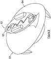
- FIG. 6is a photograph of fixation device 1 positioned on a human femur bone 41 with a graft 42 secured to the bone 41 by a fixation device 1 similar to that illustrated in Figures 1-5 .
- Figures 7-9illustrate alternate embodiments of the combination of base member 2 and affixing member 3.
- base member 38is similarly constructed as base member 2, except there are no notches 24 and 25.
- Affixing member 39is shaped to fit over base member 38 and is constructed of material that will permit member 39 to be flexed so that its lower perimeter edge 40 will expand to fit into a groove 38A formed along the lower perimeter area of interior surface 38B of base member 38 to provide a positive attachment between base member 38 and affixing member 39.
- spikes 8are positioned at the perimeter of the base member 38, then affixing member 39 will be provided with corresponding notches 45A to facilitate closure over spikes 8.
- Teeth 43extend downward from the bottom surface 44 of affixing member 39 for positioning in notch 45 shaped in the upper surface of base member 38.
- Notch 44is similarly shaped as notch 18 illustrated in Figures 1-5 .
- teeth 43will also be shaped similarly as teeth 37 in Figures 1-5 .
- FIGS 8 , 8A-8Fillustrates another embodiment wherein affixing member 45 is pivotally attached to base member 46 by a conventional pivoting construction. More particularly, base member 46 is provided with parallel separated shoulder members 47 and 48 with each having a connecting aligned passageway 49 and 50, respectively, to accept a pivot pin 51. End section 52 of affixing member 45 is shaped to pass between separated shoulder members 47 and 48. End section 52 is also provided with a passageway 53 that can be aligned with passageways 49 and 50 to permit a pivot pin 51 to extend through each of the passageways to permit affixing member 45 to pivot about pin 51.
- two pads 54 and 55extend from opposite sides 56 and 57, respectively, of affixing member 45 to provide a larger surface for the surgeon's hand to contact and provide the force necessary to attach affixing member 45 to base member 46.
- Shoulder members 47 and 48are positioned so that the teeth 58 of affixing member 54 will be positioned over notch 59 in the top surface 60 of base member 46 in similar fashion as described with respect to the Figures 1-5 embodiment.
- FIGS. 9 and Figures 9A-9Cillustrate another embodiment for affixing member 62 to grasp and secure the graft to the bone not in accordance with the invention.
- affixing member 62is pivotally secured horizontally to base member 61 by a peg or screw 63 extending upward from the top surface 64 of base member 61 and through opening 65.
- Affixing member 62is formed by two leg sections 66 and 67 that are affixed at one of their ends in a manner to be biased to form a gap 68 between the facing serrated edge surfaces 69 and 70 of leg sections 66 and 67, respectively.
- Each serrated edge surface 69 and 70is shaped having a series of teeth 71 and 72, respectively, that mate in corresponding valley areas 73 and 74, respectively when leg sections 66 and 67 are forced toward one another as illustrated in Figure 9A .
- leg sections 66 and 67are separated as illustrated in Figure 9B , the graft will be extended through gap 68.
- grasping pads 75 and 76are positioned on the top surfaces of leg sections 66 and 67, respectively, to assist the surgeon in placing the leg sections 66 and 67 in a closed position to secure the graft at the desired tension.
- opposite end 77 of leg section 66is configured to form a keeping structure 78 for retaining opposite end 79 of leg section 67.
- Opposite end 79is configured to form a latch 80 that operatively fits into keeping structure 78 to reduce gap 68 sufficiently to permit teeth 71 and 72 to hold the graft at the desired tension.
- Figures 9D-9Eillustrate an embodiment of Figure 9 wherein there are multiple keeping structures 78A, 78B and 78C to permit leg section 67 to be secured to latch 80.
- Thispermits variation in the width of gap 68 between teeth 71 and valley 74 in order to facilitate the use of grafts of different thickness.
- gap 68will be reduced to ensure that a thinner graft will be securely held in the correct tension.
- Therecan of course be more than three different keeping structures 78 to permit different ratcheting positions for securing latch 79.
Landscapes
- Health & Medical Sciences (AREA)
- Orthopedic Medicine & Surgery (AREA)
- Rehabilitation Therapy (AREA)
- Rheumatology (AREA)
- Cardiology (AREA)
- Oral & Maxillofacial Surgery (AREA)
- Transplantation (AREA)
- Engineering & Computer Science (AREA)
- Biomedical Technology (AREA)
- Heart & Thoracic Surgery (AREA)
- Vascular Medicine (AREA)
- Life Sciences & Earth Sciences (AREA)
- Animal Behavior & Ethology (AREA)
- General Health & Medical Sciences (AREA)
- Public Health (AREA)
- Veterinary Medicine (AREA)
- Surgical Instruments (AREA)
- Prostheses (AREA)
Description
- This invention relates in general to apparatus to assist in the fixation of soft tissue to bone, and more particularly to human anterior cruciate ligament (ACL) and canine cranial cruciate ligament (CrCL) reconstruction grafts.
- Prior Art. Rupture of the cranial cruciate ligament (CrCL) and subsequent osteoarthritis is a leading cause of canine hind limb lameness. Numerous techniques have been described to stabilize the canine knee or stifle following CrCL rupture to inhibit or prevent osteoarthirits. One such technique is intra-articular CrCL graft reconstruction for stabilization of CrCL deficient stifles. Various devices for initial surgical graft fixation have been utilized. These include the EndoButton CL, the Bone Mulch Screw, the RigidFix, Interference Screws, the BioScrew, the RCI screw, the SmartScrew ACL, a Synthes 6.5 cancellous screw with a spiked plastic washer or a soft tissue fixation plate, as well as various type staples, including stone and barbed staples.
- In CrCL reconstruction it is necessary to obtain a desired graft tension and then to secure the tensioned graft at the desired position on the bone. There remains in the current surgical procedure problems with obtaining the necessary graft fixation strength quickly to prevent loss of the desired graft tension. A second problem relates to the damage of the graft as it is being tensioned over the rough or sharp surfaces of the bone or fixation device used. In addition the fixation device must have the ability to maintain the graft tension during the normal activity of the person or animal during the recovery period.
- In the surgical application of these devices it is necessary that the graft to be affixed to the bone have the desired tension. The current devices are more difficult to employ during the surgical procedures than is desired. Therefore, there remains a need for a soft tissue fixation device that can be used with known arthroscopic or open surgical techniques, does not require unique application equipment, can be used with various CrCL reconstruction materials, and can affix the graft to the bone quickly and easily while still permitting the desired graft tensioning.
- Still further there remains a need to provide a device that is simple in construction and would allow the CrCL reconstruction graft to be tensioned and secured to the bone in a single step.
US 2006/0184200 relates to an apparatus for use to secure sutures and does not relate to a soft tissue function device for use in affixing a soft tissue graft to a bone.- The invention is defined by
claim 1. Therefore, one object of this disclosure is to provide a soft tissue fixation device that can be used with known arthroscopic or open surgical techniques. - Another object of this disclosure is to provide a soft tissue fixation device that does not require unique application equipment
- Still another object of this disclosure is to provide a soft tissue fixation device that can be used with various ACL or CrCL, reconstruction materials, such as from material that will over time become absorbed.
- Another object of this disclosure is to provide a soft tissue fixation device that is resistant to axial and rotational movement during the tensioning and securing of the graft to the fixation device.
- A further object of this disclosure is to provide a soft tissue fixation device that permits easier and quicker attachment of the graft to the bone while permitting the desired graft tensioning.
- Another object of this disclosure is to provide a soft tissue fixation device that when attached to the bone maintains a low profile to reduce impingement on surrounding structure, as well as reduce the visibility of its presence under the skin.
- Another further object is to construct a soft tissue fixation device that is simple in construction, and can be manufactured from absorbable materials by injection molding.
- A still further object of this disclosure is to provide improved CrCL, reconstruction procedures that permit the reconstruction graft to be tensioned and secured to the femur in one step without screws or staples.
- Other objects and advantages of this disclosure shall become apparent from the ensuing descriptions.
- Accordingly, the invention comprises a soft tissue fixation device for use in ACL, or CrCL reconstruction comprising a base member having a top and bottom surface. The base member is provided with a passageway extending from the top surface through the bottom surface and sized to allow the soft tissue to be inserted into the passageway and extend out the opposite passageway end. The bottom surface of the base member is shaped to be attachable to the bone. In a preferred example the top surface is shaped to present no sharp edges that a graft will contact during the surgical procedure. The fixation device also comprises an affixing member pivotally attached or otherwise attachable to the base member. The affixing member is constructed having a graft fixation section shaped to secure a tensioned graft between the base member and the affixing member.
- According to the invention, the base member has a notched section in the top surface extending from the passageway to a first perimeter section of the base member. The notched section is sized to accommodate at least a portion of the graft in order for the fixation device to present a lower profile when used. In one preferred example surgical grade tissue glue is spread on the bottom surface of the base member to secure the base member to the bone when the glue has dried. In another preferred example the base member is disc-shaped with its substantially flat bottom surface having at least one perpendicularly extending spike shaped to permit it to be driven into the bone to which the graft will be affixed. The spikes are shaped to hold the base member rotationally and axially in position during and after the tensioning of the graft. In another preferred example a sleeve whose interior wall surfaces form a part of the passageway extends perpendicularly from the base member bottom surface. The sleeve
- is sized to permit it to be inserted into the opening drilled into the bone to provide, along with the spikes, additional translational stability to the base member when the graft is being tensioned, as well as to prevent damage to the graft by the sharp edges of the bone tunnel.
- In another preferred example the affixing member is a clip having a generally arched shaped and provided with a series of teeth members extending downward from the lower surface of the clip member. The teeth members are positioned so that when the clip member is attached to the base member the teeth members will extend across and into the notched section of the top surface of the base member. In a more preferred example the teeth members will extend beyond the notched section to better secure any portion of the graft that may lap out from the notched section. In this preferred example the opposite ends of the clip member are shaped to fit into aligned notches positioned along perimeter sections of the bottom surface of the base member for attaching the clip member to the base member. This is accomplished by placing one of the clip member ends into its base member notch. Then through the use of a single, fluid type motion the affixing member is levered downward to force the opposite end into its base member notch thus securing the affixing member to the base member. In this example it is preferred that the clip member be constructed from flexible material, such as an acetal copolymer or other material having similar flexibility characteristics.
- In an alternate example an improved surgical procedure for cranial cruciate ligament reconstruction is provided. In this example the femur is prepared for receipt of the soft tissue fixation device in a conventional manner. This includes drilling a bone tunnel from the intra-articular origin of the CrCL, to the center of the lateral aspect of the femoral condyle. The base member is aligned with the bone tunnel so that its sleeve is over the pilot hole. The base member is then tapped into place with an osteotomy mallet. If the base member is not provided with a sleeve, then the base member passageway is positioned over the pilot hole and secured in place with the use of surgical grade tissue glue. The graft is passed through the femoral tunnel and the sleeve. That portion of the graft extending from the sleeve is positioned across the top surface notch of the base member and pulled to achieve the desired tension. The pivoting end of the clip member is placed in one of the bottom surface notches. The clip member is then in one motion pivoted downward until the attaching end of the clip member is secured in the opposite bottom surface notch. This action causes the teeth of the clip member to grab the graft and secure the graft between the base member and the clip member sufficiently to maintain the desired tension.
- The accompanying drawings illustrate examples of this disclosure. However, it is to be understood that these examples are not intended to be exhaustive, nor limiting of the disclosure. They are but examples of some of the forms in which the disclosure may be practiced.
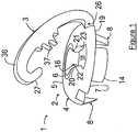
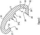
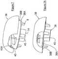
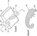
Figure 1 is three-quarter top perspective view of a preferred example of the soft tissue fixation device according to the invention illustrated having the pivoting end of the clip member in position to be pivoted by the surgeon into an attached or locked position.Figure 2 is a three-quarter bottom perspective view of the base member of the soft tissue fixation device ofFigure 1 .Figure 3 is a bottom view of the base member of the soft tissue fixation device ofFigure 1 .Figure 4 is a three-quarter perspective view of the clip member forming the soft tissue fixation device ofFigure 1 .Figure 5 is a cross-sectional view taken along Section Lines I-I ofFigure 4 .Figure 6 is a photograph of soft tissue affixed in position by a preferred example of the fixation device of this disclosure attached to a human femur.Figure 7 is an exploded view of an alternate example of the soft tissue fixation device according to the invention illustrating the affixing member attached to the base member by hinge means.Figure 7A is a side view of the base member and affixing member in connecting relationship ofFigure 7 .Figure 7B is a cross-sectional view taken along Section Lines II-II ofFigure 7A .Figure 7C is a bottom view ofFigure 7A .Figure 8 is a three-quarter perspective view of another alternate embodiment of the soft tissue fixation device of this invention illustrating the affixing member pivotally attachable to the base member.Figure 8A is a three-quarter perspective view ofFigure 8 wherein the affixing member is engaged with thebase member 8.Figure 8B is a top three-quarter perspective view of the base member ofFigure 8 Figure 8C is a top view of the base member ofFigure 8 without the affixing member attached.Figure 8D is side view of the base member ofFigure 8 without the affixing member attached.Figure 8E is a bottom three-quarter perspective view of the affixing member ofFigure 8 .Figure 8F is a cross-sectional view taken along lines III-III ofFigure 8E .Figure 9 is a top three-quarter perspective view of an alternate fixation device of this disclosure.Figure 9A is a top three-quarter perspective view of the affixing member ofFigure 9 illustrated in a closed position.Figure 9B is a top three-quarter perspective view of the affixing member ofFigure 9 illustrated in an open position.Figure 9C is a side view of the affixing member ofFigure 9B .- Without any intent to limit the scope of this invention, reference is made to the figures in describing the preferred embodiments of the invention. Although the preferred embodiments of the invention will be described utilizing the invention in CrCL reconstruction, this in no way is meant to limit the invention to such use, as it will be appreciated it has use in ACL reconstruction and other human and animal applications.
- The device of this invention is particularly useful in ACL or CrCL reconstruction to fix a soft tissue graft to the bone of a human or dog suffering from an ACL or CrCL tear. Referring now to
Figure 1 , a preferred embodiment of the softtissue fixation device 1 includes abase member 2 and agraft affixing member 3. The primary function ofbase member 2 is to provide a stable platform to allow the soft tissue graft to be tensioned during the procedure to attach the graft to the bone. More particularly,base member 2 should be constructed to minimize the axial and rotational movement of the base member during the graft tensioning step.Base member 2 should further be constructed to minimize potential tearing of the graft during the tensioning step. On the other hand the primary function of affixingmember 3 is to affix and maintain the soft tissue graft in the desired tensioned position on thebase member 2. - That portion of
base member 2 that will extend above the bone surface when attached to the bone is preferably is constructed to have a low profile. In a preferredembodiment base member 2 will be constructed havingtop surface 4 with a curved perimeter top surface section5 surrounding a flat topsurface center section 6 and a substantially flatbottom surface 7. The height ofbase member 2 must be such to permit the attachment of affixingmember 3.Base member 2 may be secured in the desired position to the femur bone by the use of known surgical grade tissue glue. In another embodiment extending downward frombottom surface 7 is at least one securing member, such asspike 8. It is preferred that there be at least threespikes 8 equally spaced about the perimeter edge ofbottom surface 7 to provide greater stability against rotation and lift forces onbase member 2 during the tensioning of the graft. It is further preferred that spikes8 be shaped to be easily driven into the bone, holdbase member 2 in place during the tensioning of the graft, as well as minimize rotational and axial movement ofbase member 2 during the tensioning and securing of the graft to thefixation device 1. One preferred shape ofspikes 8 is a tubular or solid shaped spike having a pyramidal shaped bottom section. Other shapes ofspikes 8 include a tubular shaped spike with triangular cross-sectional shape bottom section. Spikes having a star-shaped tubular section can also be employed. If desired known surgical grade tissue glue can also be used in conjunction with aspiked base member 2. - The structural design of
spikes 8 are preferably selected to provide ease of attachment to the bone while providing the desired stability to thebase member 2 during the graft tensioning process. If desired there could be multiple rows ofspikes 8. The shape ofspike 8 must permit their insertion into the femur bone and to resist shearing caused by rotational forces onbase member 3. In addition the shape ofspike 8 should be resistant to upward forces that might causebase member 2 to become detached from the bone during the graft tensioning process. In one preferred embodiment these objectives are achieved utilizingspikes 8 having a substantiallyrectangular base 9 attached tobottom surface 7 withside 10 ofbase 9 tracking a portion of the perimeter of thebottom surface 7. Theopposite side 11 of the base is provided with an arc-shapedportion 12 that withside 10 culminates to form ashape edge 13. Other known shapes can be utilized that will provide the desired objectives. - In an embodiment according to the invention illustrated in
Figure 2 , asleeve 14 will extend downward from thecenter section 15 ofbottom surface 7.Sleeve 14 will have an outside diameter that permits its snug insertion into a channel drilled into the femur bone.Sleeve 14 will also form apassageway 16 that will provide protection to the graft being attached to the bone. According to the invention all edges ofsleeve 14 that may be contacted with the graft be rounded and smooth to prevent cutting or tearing of the graft.Passageway 16 extends along the vertical center axis ofbase member 2 andsleeve 14.Passageway 16 is shaped to permit the graft to pass through thepassageway 16, but has no sharp corners that might damage the graft that is held against thepassageway wall 17. Thetop surface 4 is also provided with anotch 18 that extends frompassageway 16 to theperimeter 19 oftop surface 4. Thenotch 18 should have a width to accommodate at least a substantial portion of the graft. Preferably, notch18 will also have a depth to accommodate at least a substantial portion of the graft to permit a lower profile design offixation device 1. It is also preferred that theupper edge sections side walls walls forming notch 18. - As illustrated in
Figures 2 and3 ,bottom surface 7 ofbase member 2 is provided with twoaligned notches Notches member 3, and more preferably the positioning of affixingmember 3 over at least a portion oftop surface notch 18. - As illustrated in
Figures 4 and5 , affixingmember 3 is constructed having opposingcurved end sections End section 26 includes with aleg member 28 having a flatupper surface 29 that can be positioned on theflat floor surface 30 ofnotch 24 and of a length to preventleg member 28 from slipping out ofnotch 24. Thesecond leg member 31 ofend section 26 forms an acute angle "a" withleg member 28. In a more preferred embodiment angle "a" is less than 60°. In a more preferred embodiment arounded notch 32 is formed by cutting into theinterior surfaces leg members end section 26, yet provides sufficient strength that theend section 26 will not crack when the twoleg members end 27 is similar constructed except that itsleg member 34 is provided with arounded end 35 to permit easier attachment of affixingmember 3. - Affixing
member 3 has amiddle section 36 provided withteeth 37, or other similar known grabbing elements, that will extend across and intonotch 18 when affixingmember 3 is secured tobase member 2 to hold the graft in the desired tensioned position. In apreferred embodiment teeth 37 will extend on either side ofnotch 18 to hold any portion of the graft that may overlapnotch 18. In order to facilitate clip closure and/or minimize damage to the soft tissue graft, it is also preferred that the length of theteeth 37 be decreased as they are positioned away from thecenter teeth 37a. - In the surgical procedure utilizing
fixation device 1, a tunnel is first drilled from the intra-articular origin of the CrCL to the center of the lateral aspect of each femoral condyle. For a mid-sized dog (approximately 32 Kg) this canal will be approximately 4.5 mm in diameter.Base member 2 is aligned with the bone tunnel so that itssleeve 14 is over the pilot hole. Base member is then tapped into place with an osteotomy mallet. The graft is passed through the femoral tunnel andsleeve 9, Pivoting end 26 of affixingmember 3 is placed inbottom surface notch 24. That portion of the graft extending from thesleeve 14 is positioned acrosstop surface notch 18 ofbase member 2 and pulled to achieve the desired tensioning.Member 3 is then in one motion pivoted downward until latchingend 27 of affixingmember 3 is secured in oppositebottom surface notch 19. This action causesteeth 37 of affixingmember 3 to grab the graft and secure the graft betweenbase member 2 and affixingmember 3 sufficiently to maintain the desired tensioning.Figure 6 is a photograph offixation device 1 positioned on ahuman femur bone 41 with agraft 42 secured to thebone 41 by afixation device 1 similar to that illustrated inFigures 1-5 . Figures 7-9 illustrate alternate embodiments of the combination ofbase member 2 and affixingmember 3. InFigures 7, 7A ,7B and 7C ,base member 38 is similarly constructed asbase member 2, except there are nonotches member 39 is shaped to fit overbase member 38 and is constructed of material that will permitmember 39 to be flexed so that itslower perimeter edge 40 will expand to fit into agroove 38A formed along the lower perimeter area ofinterior surface 38B ofbase member 38 to provide a positive attachment betweenbase member 38 and affixingmember 39. When spikes8 are positioned at the perimeter of thebase member 38, then affixingmember 39 will be provided withcorresponding notches 45A to facilitate closure overspikes 8.Teeth 43 extend downward from thebottom surface 44 of affixingmember 39 for positioning innotch 45 shaped in the upper surface ofbase member 38.Notch 44 is similarly shaped asnotch 18 illustrated inFigures 1-5 . In apreferred embodiment teeth 43 will also be shaped similarly asteeth 37 inFigures 1-5 .Figures 8 ,8A-8F illustrates another embodiment wherein affixingmember 45 is pivotally attached tobase member 46 by a conventional pivoting construction. More particularly,base member 46 is provided with parallel separatedshoulder members passageway pivot pin 51.End section 52 of affixingmember 45 is shaped to pass between separatedshoulder members End section 52 is also provided with apassageway 53 that can be aligned withpassageways pivot pin 51 to extend through each of the passageways to permit affixingmember 45 to pivot aboutpin 51. In a preferred embodiment twopads opposite sides member 45 to provide a larger surface for the surgeon's hand to contact and provide the force necessary to attach affixingmember 45 tobase member 46.Shoulder members member 54 will be positioned overnotch 59 in thetop surface 60 ofbase member 46 in similar fashion as described with respect to theFigures 1-5 embodiment.Figure 9 andFigures 9A-9C illustrate another embodiment for affixingmember 62 to grasp and secure the graft to the bone not in accordance with the invention. In thisembodiment affixing member 62 is pivotally secured horizontally tobase member 61 by a peg or screw63 extending upward from thetop surface 64 ofbase member 61 and throughopening 65. Affixingmember 62 is formed by twoleg sections gap 68 between the facing serrated edge surfaces69 and70 ofleg sections serrated edge surface teeth valley areas leg sections Figure 9A . Whenleg sections Figure 9B , the graft will be extended throughgap 68. In anembodiment grasping pads leg sections leg sections leg sections opposite end 77 ofleg section 66 is configured to form a keepingstructure 78 for retainingopposite end 79 ofleg section 67. Oppositeend 79 is configured to form alatch 80 that operatively fits into keepingstructure 78 to reducegap 68 sufficiently to permitteeth Figures 9D-9E illustrate an embodiment ofFigure 9 wherein there are multiple keepingstructures leg section 67 to be secured to latch80. This permits variation in the width ofgap 68 betweenteeth 71 andvalley 74 in order to facilitate the use of grafts of different thickness. Whenleg section 67 is in the position shown as67A,gap 68 will be reduced to ensure that a thinner graft will be securely held in the correct tension. There can of course be more than threedifferent keeping structures 78 to permit different ratcheting positions for securinglatch 79.- There are of course other alternate embodiments which are obvious from the foregoing descriptions of the invention which are intended to be included within the scope of the invention as defined by the following claims.
Claims (10)
- A soft tissue fixation device (1) for use in affixing a soft tissue graft to a bone in an anterior or cranial cruciate ligament reconstruction comprising:a base member (2) having a passageway (16) extending from its top surface (4) through to its bottom surface (7), the passageway being of sufficient size to permit the graft to be extended through the passageway and having no sharp corners that might damage the graft held against the passageway wall (17), wherein the base member includes a notched section (18) in the top surface (4) extending from the passageway (16) to a first perimeter section of the base;an affixing member (3) pivotally attached to the base member having an affixing section shaped to affix the graft between the base member (2) and the affixing member (3), wherein the affixing section is shaped to accommodate various shaped grafts, said affixing section having at least one tooth member (37) extending from a bottom surface of the affixing section and into the notched section.
- The soft tissue fixation device according to claim 1, wherein the base member (2) further comprises a tubular sleeve (14) extending from the bottom surface (7) of the base member and forming a portion of the passageway (16).
- The soft tissue fixation device according to claim 2, wherein the tubular sleeve (14) has an exterior shape to permit it to be inserted into a bone tunnel.
- The soft tissue fixation device according to claim 1 wherein there are at least three securing devices (8) equally spaced from one another and extending downward from the bottom surface (7) of the base member (2).
- The soft tissue fixation device according to claim 4 wherein the securing device (8) extends from the bottom surface of the base member at an angle less than 90°.
- The soft tissue fixation device according to claim 4 wherein the securing device has at least one curved exterior surface extending from the bottom surface of the base member.
- The soft tissue fixation device of claim 1 comprising: at least one spike member (8) extending perpendicularly from the bottom surface; and an affixing member having at least one attaching section, the at least one attaching section constructed and shaped to be attachable to the base member to position the affixing section over the notched section of the base member.
- The soft tissue fixation device according to claim 7 wherein the attaching section of the affixing member is pivotally attached to at least one shoulder (47, 48) member of the base member (2).
- The soft tissue fixation device according to claim 1, wherein the affixing member is a clip being constructed from flexible material.
- The soft tissue fixation device according to claim 1, wherein said device is bioabsorbable.
Applications Claiming Priority (2)
| Application Number | Priority Date | Filing Date | Title |
|---|---|---|---|
| US11/461,214US8603115B2 (en) | 2006-07-31 | 2006-07-31 | Soft tissue fixation device |
| PCT/US2007/017269WO2008016685A2 (en) | 2006-07-31 | 2007-07-31 | Soft tissue fixation device |
Publications (3)
| Publication Number | Publication Date |
|---|---|
| EP2076189A2 EP2076189A2 (en) | 2009-07-08 |
| EP2076189A4 EP2076189A4 (en) | 2012-03-28 |
| EP2076189B1true EP2076189B1 (en) | 2020-07-22 |
Family
ID=38987305
Family Applications (1)
| Application Number | Title | Priority Date | Filing Date |
|---|---|---|---|
| EP07811021.0AActiveEP2076189B1 (en) | 2006-07-31 | 2007-07-31 | Soft tissue fixation device |
Country Status (4)
| Country | Link |
|---|---|
| US (2) | US8603115B2 (en) |
| EP (1) | EP2076189B1 (en) |
| CA (1) | CA2663535C (en) |
| WO (1) | WO2008016685A2 (en) |
Families Citing this family (5)
| Publication number | Priority date | Publication date | Assignee | Title |
|---|---|---|---|---|
| US9056003B2 (en) | 2013-01-25 | 2015-06-16 | Smith & Nephew, Inc. | Tissue graft fixation |
| EP3280335B1 (en) | 2015-04-10 | 2024-02-21 | Board of Supervisors of Louisiana State University and Agricultural and Mechanical College | Soft tissue tensioning and fixation device |
| US20170119374A1 (en)* | 2015-11-03 | 2017-05-04 | Cook Incorporated | Cam suture retention mechanism |
| WO2017172688A1 (en)* | 2016-03-29 | 2017-10-05 | Brett Sanders | Apparatus and method for coupling soft tissue to bone |
| US11426285B2 (en)* | 2019-09-05 | 2022-08-30 | Howmedica Osteonics Corp. | Truss glenoid augment |
Citations (4)
| Publication number | Priority date | Publication date | Assignee | Title |
|---|---|---|---|---|
| FR2676356A1 (en)* | 1991-05-13 | 1992-11-20 | Cendis Medical | Fixation element for ligaments |
| US5425767A (en)* | 1992-11-02 | 1995-06-20 | Sulzer Medizinaltechnik Ag | Anchor for an artificial ligament |
| WO1997030649A1 (en)* | 1996-02-20 | 1997-08-28 | Medicinelodge, Inc. | Ligament bone anchor and method for its use |
| US6235058B1 (en)* | 1998-10-19 | 2001-05-22 | Douglas B. Huene | Bone plug anchoring device and methods for anchoring one or more tendons or other grafts using the bone plug anchoring device |
Family Cites Families (17)
| Publication number | Priority date | Publication date | Assignee | Title |
|---|---|---|---|---|
| US2502034A (en)* | 1946-12-06 | 1950-03-28 | Gordon O Bowie | Separable button |
| DE2853289C2 (en)* | 1978-12-09 | 1980-12-18 | B. Braun Melsungen Ag, 3508 Melsungen | Button for surgical use |
| US4988351A (en)* | 1989-01-06 | 1991-01-29 | Concept, Inc. | Washer for use with cancellous screw for attaching soft tissue to bone |
| US5078731A (en)* | 1990-06-05 | 1992-01-07 | Hayhurst John O | Suture clip |
| US5224946A (en)* | 1990-07-02 | 1993-07-06 | American Cyanamid Company | Bone anchor and method of anchoring a suture to a bone |
| US5258015A (en)* | 1991-05-03 | 1993-11-02 | American Cyanamid Company | Locking filament caps |
| CA2124651C (en)* | 1993-08-20 | 2004-09-28 | David T. Green | Apparatus and method for applying and adjusting an anchoring device |
| US6235057B1 (en)* | 1995-01-24 | 2001-05-22 | Smith & Nephew, Inc. | Method for soft tissue reconstruction |
| IT1284177B1 (en) | 1996-06-27 | 1998-05-08 | Gabriele Valenti | STRAIGHTENER FOR SURGICAL SUTURES |
| US5951590A (en)* | 1998-06-09 | 1999-09-14 | Goldfarb; Michael A. | Soft tissue suture anchor |
| US6066160A (en)* | 1998-11-23 | 2000-05-23 | Quickie Llc | Passive knotless suture terminator for use in minimally invasive surgery and to facilitate standard tissue securing |
| US6306159B1 (en)* | 1998-12-23 | 2001-10-23 | Depuy Orthopaedics, Inc. | Meniscal repair device |
| US6132442A (en)* | 1999-03-25 | 2000-10-17 | Smith & Nephew | Graft clamp |
| JP2002062586A (en)* | 2000-08-17 | 2002-02-28 | Iwasaki Electric Co Ltd | Short arc discharge lamp with reflector |
| US7625387B2 (en)* | 2003-11-05 | 2009-12-01 | Applied Medical Resources Corporation | Suture securing device and method |
| US7422012B2 (en) | 2005-01-10 | 2008-09-09 | Gary Pinns | Apparatus and method for controlling unpleasant human breath odor |
| US20060184201A1 (en) | 2005-02-17 | 2006-08-17 | James Jervis E | Suture retainer with suture guide and method of using a suture retainer with a suture guide |
- 2006
- 2006-07-31USUS11/461,214patent/US8603115B2/enactiveActive
- 2007
- 2007-07-31CACA2663535Apatent/CA2663535C/enactiveActive
- 2007-07-31WOPCT/US2007/017269patent/WO2008016685A2/enactiveApplication Filing
- 2007-07-31EPEP07811021.0Apatent/EP2076189B1/enactiveActive
- 2013
- 2013-12-03USUS14/094,906patent/US9044315B2/enactiveActive
Patent Citations (4)
| Publication number | Priority date | Publication date | Assignee | Title |
|---|---|---|---|---|
| FR2676356A1 (en)* | 1991-05-13 | 1992-11-20 | Cendis Medical | Fixation element for ligaments |
| US5425767A (en)* | 1992-11-02 | 1995-06-20 | Sulzer Medizinaltechnik Ag | Anchor for an artificial ligament |
| WO1997030649A1 (en)* | 1996-02-20 | 1997-08-28 | Medicinelodge, Inc. | Ligament bone anchor and method for its use |
| US6235058B1 (en)* | 1998-10-19 | 2001-05-22 | Douglas B. Huene | Bone plug anchoring device and methods for anchoring one or more tendons or other grafts using the bone plug anchoring device |
Also Published As
| Publication number | Publication date |
|---|---|
| US8603115B2 (en) | 2013-12-10 |
| CA2663535A1 (en) | 2008-02-07 |
| US9044315B2 (en) | 2015-06-02 |
| WO2008016685A2 (en) | 2008-02-07 |
| EP2076189A2 (en) | 2009-07-08 |
| US20080027441A1 (en) | 2008-01-31 |
| US20140236195A1 (en) | 2014-08-21 |
| CA2663535C (en) | 2015-05-19 |
| WO2008016685A3 (en) | 2008-06-12 |
| EP2076189A4 (en) | 2012-03-28 |
Similar Documents
| Publication | Publication Date | Title |
|---|---|---|
| EP1281376B1 (en) | An anchoring device | |
| AU2005215772B2 (en) | Soft tissue repair apparatus and method | |
| US7303577B1 (en) | Apparatus and method for use in repairs of injured soft tissue | |
| JP4455795B2 (en) | Device for attaching soft tissue to bone | |
| AU2016238296B2 (en) | Joint repair system | |
| JP4068159B2 (en) | Device for anchoring an object to a bone | |
| US9044315B2 (en) | Soft tissue fixation device | |
| US20220079627A1 (en) | Knotless syndesmosis system | |
| IL118557A (en) | Fastener and fastening method, particularly for fastening sutures to bone | |
| IES20060551A2 (en) | Method and apparatus for internal fixation of an acromioclavicular joint dislocation of the shoulder | |
| IES84791Y1 (en) | Method and apparatus for internal fixation of an acromioclavicular joint dislocation of the shoulder |
Legal Events
| Date | Code | Title | Description |
|---|---|---|---|
| PUAI | Public reference made under article 153(3) epc to a published international application that has entered the european phase | Free format text:ORIGINAL CODE: 0009012 | |
| 17P | Request for examination filed | Effective date:20090227 | |
| AK | Designated contracting states | Kind code of ref document:A2 Designated state(s):AT BE BG CH CY CZ DE DK EE ES FI FR GB GR HU IE IS IT LI LT LU LV MC MT NL PL PT RO SE SI SK TR | |
| AX | Request for extension of the european patent | Extension state:AL BA HR MK RS | |
| DAX | Request for extension of the european patent (deleted) | ||
| RAP1 | Party data changed (applicant data changed or rights of an application transferred) | Owner name:BOARD OF SUPERVISORS OF LOUISIANA STATE UNIVERSITY | |
| A4 | Supplementary search report drawn up and despatched | Effective date:20120223 | |
| RIC1 | Information provided on ipc code assigned before grant | Ipc:A61F 2/08 20060101ALI20120217BHEP Ipc:A61B 17/58 20060101AFI20120217BHEP | |
| 17Q | First examination report despatched | Effective date:20150819 | |
| STAA | Information on the status of an ep patent application or granted ep patent | Free format text:STATUS: EXAMINATION IS IN PROGRESS | |
| GRAJ | Information related to disapproval of communication of intention to grant by the applicant or resumption of examination proceedings by the epo deleted | Free format text:ORIGINAL CODE: EPIDOSDIGR1 | |
| GRAP | Despatch of communication of intention to grant a patent | Free format text:ORIGINAL CODE: EPIDOSNIGR1 | |
| GRAP | Despatch of communication of intention to grant a patent | Free format text:ORIGINAL CODE: EPIDOSNIGR1 | |
| STAA | Information on the status of an ep patent application or granted ep patent | Free format text:STATUS: GRANT OF PATENT IS INTENDED | |
| INTG | Intention to grant announced | Effective date:20200213 | |
| GRAS | Grant fee paid | Free format text:ORIGINAL CODE: EPIDOSNIGR3 | |
| GRAA | (expected) grant | Free format text:ORIGINAL CODE: 0009210 | |
| STAA | Information on the status of an ep patent application or granted ep patent | Free format text:STATUS: THE PATENT HAS BEEN GRANTED | |
| AK | Designated contracting states | Kind code of ref document:B1 Designated state(s):AT BE BG CH CY CZ DE DK EE ES FI FR GB GR HU IE IS IT LI LT LU LV MC MT NL PL PT RO SE SI SK TR | |
| REG | Reference to a national code | Ref country code:GB Ref legal event code:FG4D | |
| REG | Reference to a national code | Ref country code:CH Ref legal event code:EP | |
| REG | Reference to a national code | Ref country code:DE Ref legal event code:R096 Ref document number:602007060476 Country of ref document:DE | |
| REG | Reference to a national code | Ref country code:AT Ref legal event code:REF Ref document number:1292638 Country of ref document:AT Kind code of ref document:T Effective date:20200815 | |
| REG | Reference to a national code | Ref country code:IE Ref legal event code:FG4D | |
| REG | Reference to a national code | Ref country code:CH Ref legal event code:NV Representative=s name:ISLER AND PEDRAZZINI AG, CH | |
| REG | Reference to a national code | Ref country code:LT Ref legal event code:MG4D | |
| REG | Reference to a national code | Ref country code:AT Ref legal event code:MK05 Ref document number:1292638 Country of ref document:AT Kind code of ref document:T Effective date:20200722 | |
| PG25 | Lapsed in a contracting state [announced via postgrant information from national office to epo] | Ref country code:SE Free format text:LAPSE BECAUSE OF FAILURE TO SUBMIT A TRANSLATION OF THE DESCRIPTION OR TO PAY THE FEE WITHIN THE PRESCRIBED TIME-LIMIT Effective date:20200722 Ref country code:FI Free format text:LAPSE BECAUSE OF FAILURE TO SUBMIT A TRANSLATION OF THE DESCRIPTION OR TO PAY THE FEE WITHIN THE PRESCRIBED TIME-LIMIT Effective date:20200722 Ref country code:BG Free format text:LAPSE BECAUSE OF FAILURE TO SUBMIT A TRANSLATION OF THE DESCRIPTION OR TO PAY THE FEE WITHIN THE PRESCRIBED TIME-LIMIT Effective date:20201022 Ref country code:LT Free format text:LAPSE BECAUSE OF FAILURE TO SUBMIT A TRANSLATION OF THE DESCRIPTION OR TO PAY THE FEE WITHIN THE PRESCRIBED TIME-LIMIT Effective date:20200722 Ref country code:AT Free format text:LAPSE BECAUSE OF FAILURE TO SUBMIT A TRANSLATION OF THE DESCRIPTION OR TO PAY THE FEE WITHIN THE PRESCRIBED TIME-LIMIT Effective date:20200722 Ref country code:PT Free format text:LAPSE BECAUSE OF FAILURE TO SUBMIT A TRANSLATION OF THE DESCRIPTION OR TO PAY THE FEE WITHIN THE PRESCRIBED TIME-LIMIT Effective date:20201123 Ref country code:GR Free format text:LAPSE BECAUSE OF FAILURE TO SUBMIT A TRANSLATION OF THE DESCRIPTION OR TO PAY THE FEE WITHIN THE PRESCRIBED TIME-LIMIT Effective date:20201023 Ref country code:ES Free format text:LAPSE BECAUSE OF FAILURE TO SUBMIT A TRANSLATION OF THE DESCRIPTION OR TO PAY THE FEE WITHIN THE PRESCRIBED TIME-LIMIT Effective date:20200722 | |
| PG25 | Lapsed in a contracting state [announced via postgrant information from national office to epo] | Ref country code:IS Free format text:LAPSE BECAUSE OF FAILURE TO SUBMIT A TRANSLATION OF THE DESCRIPTION OR TO PAY THE FEE WITHIN THE PRESCRIBED TIME-LIMIT Effective date:20201122 Ref country code:PL Free format text:LAPSE BECAUSE OF FAILURE TO SUBMIT A TRANSLATION OF THE DESCRIPTION OR TO PAY THE FEE WITHIN THE PRESCRIBED TIME-LIMIT Effective date:20200722 Ref country code:LV Free format text:LAPSE BECAUSE OF FAILURE TO SUBMIT A TRANSLATION OF THE DESCRIPTION OR TO PAY THE FEE WITHIN THE PRESCRIBED TIME-LIMIT Effective date:20200722 | |
| PG25 | Lapsed in a contracting state [announced via postgrant information from national office to epo] | Ref country code:NL Free format text:LAPSE BECAUSE OF FAILURE TO SUBMIT A TRANSLATION OF THE DESCRIPTION OR TO PAY THE FEE WITHIN THE PRESCRIBED TIME-LIMIT Effective date:20200722 | |
| REG | Reference to a national code | Ref country code:DE Ref legal event code:R097 Ref document number:602007060476 Country of ref document:DE | |
| REG | Reference to a national code | Ref country code:BE Ref legal event code:MM Effective date:20200731 | |
| PG25 | Lapsed in a contracting state [announced via postgrant information from national office to epo] | Ref country code:DK Free format text:LAPSE BECAUSE OF FAILURE TO SUBMIT A TRANSLATION OF THE DESCRIPTION OR TO PAY THE FEE WITHIN THE PRESCRIBED TIME-LIMIT Effective date:20200722 Ref country code:EE Free format text:LAPSE BECAUSE OF FAILURE TO SUBMIT A TRANSLATION OF THE DESCRIPTION OR TO PAY THE FEE WITHIN THE PRESCRIBED TIME-LIMIT Effective date:20200722 Ref country code:CZ Free format text:LAPSE BECAUSE OF FAILURE TO SUBMIT A TRANSLATION OF THE DESCRIPTION OR TO PAY THE FEE WITHIN THE PRESCRIBED TIME-LIMIT Effective date:20200722 Ref country code:LU Free format text:LAPSE BECAUSE OF NON-PAYMENT OF DUE FEES Effective date:20200731 Ref country code:MC Free format text:LAPSE BECAUSE OF FAILURE TO SUBMIT A TRANSLATION OF THE DESCRIPTION OR TO PAY THE FEE WITHIN THE PRESCRIBED TIME-LIMIT Effective date:20200722 Ref country code:RO Free format text:LAPSE BECAUSE OF FAILURE TO SUBMIT A TRANSLATION OF THE DESCRIPTION OR TO PAY THE FEE WITHIN THE PRESCRIBED TIME-LIMIT Effective date:20200722 | |
| PLBE | No opposition filed within time limit | Free format text:ORIGINAL CODE: 0009261 | |
| REG | Reference to a national code | Ref country code:DE Ref legal event code:R082 Ref document number:602007060476 Country of ref document:DE Representative=s name:MURGITROYD GERMANY PATENTANWALTSGESELLSCHAFT M, DE Ref country code:DE Ref legal event code:R082 Ref document number:602007060476 Country of ref document:DE Representative=s name:MURGITROYD & COMPANY, DE | |
| STAA | Information on the status of an ep patent application or granted ep patent | Free format text:STATUS: NO OPPOSITION FILED WITHIN TIME LIMIT | |
| PG25 | Lapsed in a contracting state [announced via postgrant information from national office to epo] | Ref country code:BE Free format text:LAPSE BECAUSE OF NON-PAYMENT OF DUE FEES Effective date:20200731 | |
| 26N | No opposition filed | Effective date:20210423 | |
| PG25 | Lapsed in a contracting state [announced via postgrant information from national office to epo] | Ref country code:SK Free format text:LAPSE BECAUSE OF FAILURE TO SUBMIT A TRANSLATION OF THE DESCRIPTION OR TO PAY THE FEE WITHIN THE PRESCRIBED TIME-LIMIT Effective date:20200722 | |
| PG25 | Lapsed in a contracting state [announced via postgrant information from national office to epo] | Ref country code:IE Free format text:LAPSE BECAUSE OF NON-PAYMENT OF DUE FEES Effective date:20200731 Ref country code:SI Free format text:LAPSE BECAUSE OF FAILURE TO SUBMIT A TRANSLATION OF THE DESCRIPTION OR TO PAY THE FEE WITHIN THE PRESCRIBED TIME-LIMIT Effective date:20200722 | |
| REG | Reference to a national code | Ref country code:NL Ref legal event code:MP Effective date:20200722 | |
| PG25 | Lapsed in a contracting state [announced via postgrant information from national office to epo] | Ref country code:TR Free format text:LAPSE BECAUSE OF FAILURE TO SUBMIT A TRANSLATION OF THE DESCRIPTION OR TO PAY THE FEE WITHIN THE PRESCRIBED TIME-LIMIT Effective date:20200722 Ref country code:MT Free format text:LAPSE BECAUSE OF FAILURE TO SUBMIT A TRANSLATION OF THE DESCRIPTION OR TO PAY THE FEE WITHIN THE PRESCRIBED TIME-LIMIT Effective date:20200722 Ref country code:CY Free format text:LAPSE BECAUSE OF FAILURE TO SUBMIT A TRANSLATION OF THE DESCRIPTION OR TO PAY THE FEE WITHIN THE PRESCRIBED TIME-LIMIT Effective date:20200722 | |
| PGFP | Annual fee paid to national office [announced via postgrant information from national office to epo] | Ref country code:IT Payment date:20230720 Year of fee payment:17 Ref country code:GB Payment date:20230727 Year of fee payment:17 Ref country code:CH Payment date:20230802 Year of fee payment:17 | |
| PGFP | Annual fee paid to national office [announced via postgrant information from national office to epo] | Ref country code:FR Payment date:20230725 Year of fee payment:17 Ref country code:DE Payment date:20230727 Year of fee payment:17 | |
| REG | Reference to a national code | Ref country code:DE Ref legal event code:R119 Ref document number:602007060476 Country of ref document:DE | |
| REG | Reference to a national code | Ref country code:CH Ref legal event code:PL | |
| GBPC | Gb: european patent ceased through non-payment of renewal fee | Effective date:20240731 | |
| PG25 | Lapsed in a contracting state [announced via postgrant information from national office to epo] | Ref country code:DE Free format text:LAPSE BECAUSE OF NON-PAYMENT OF DUE FEES Effective date:20250201 | |
| PG25 | Lapsed in a contracting state [announced via postgrant information from national office to epo] | Ref country code:CH Free format text:LAPSE BECAUSE OF NON-PAYMENT OF DUE FEES Effective date:20240731 | |
| PG25 | Lapsed in a contracting state [announced via postgrant information from national office to epo] | Ref country code:FR Free format text:LAPSE BECAUSE OF NON-PAYMENT OF DUE FEES Effective date:20240731 | |
| PG25 | Lapsed in a contracting state [announced via postgrant information from national office to epo] | Ref country code:GB Free format text:LAPSE BECAUSE OF NON-PAYMENT OF DUE FEES Effective date:20240731 | |
| PG25 | Lapsed in a contracting state [announced via postgrant information from national office to epo] | Ref country code:IT Free format text:LAPSE BECAUSE OF NON-PAYMENT OF DUE FEES Effective date:20240731 |