EP2074933B1 - Method of analysing and processing fluorescent images - Google Patents
Method of analysing and processing fluorescent imagesDownload PDFInfo
- Publication number
- EP2074933B1 EP2074933B1EP08170247AEP08170247AEP2074933B1EP 2074933 B1EP2074933 B1EP 2074933B1EP 08170247 AEP08170247 AEP 08170247AEP 08170247 AEP08170247 AEP 08170247AEP 2074933 B1EP2074933 B1EP 2074933B1
- Authority
- EP
- European Patent Office
- Prior art keywords
- image
- analysing
- processing
- intensity
- threshold value
- Prior art date
- Legal status (The legal status is an assumption and is not a legal conclusion. Google has not performed a legal analysis and makes no representation as to the accuracy of the status listed.)
- Not-in-force
Links
Images


Classifications
- G—PHYSICS
- G02—OPTICS
- G02B—OPTICAL ELEMENTS, SYSTEMS OR APPARATUS
- G02B21/00—Microscopes
- G02B21/16—Microscopes adapted for ultraviolet illumination ; Fluorescence microscopes
- A—HUMAN NECESSITIES
- A61—MEDICAL OR VETERINARY SCIENCE; HYGIENE
- A61B—DIAGNOSIS; SURGERY; IDENTIFICATION
- A61B1/00—Instruments for performing medical examinations of the interior of cavities or tubes of the body by visual or photographical inspection, e.g. endoscopes; Illuminating arrangements therefor
- A61B1/04—Instruments for performing medical examinations of the interior of cavities or tubes of the body by visual or photographical inspection, e.g. endoscopes; Illuminating arrangements therefor combined with photographic or television appliances
- A61B1/043—Instruments for performing medical examinations of the interior of cavities or tubes of the body by visual or photographical inspection, e.g. endoscopes; Illuminating arrangements therefor combined with photographic or television appliances for fluorescence imaging
- A—HUMAN NECESSITIES
- A61—MEDICAL OR VETERINARY SCIENCE; HYGIENE
- A61B—DIAGNOSIS; SURGERY; IDENTIFICATION
- A61B5/00—Measuring for diagnostic purposes; Identification of persons
- A61B5/0059—Measuring for diagnostic purposes; Identification of persons using light, e.g. diagnosis by transillumination, diascopy, fluorescence
- G—PHYSICS
- G02—OPTICS
- G02B—OPTICAL ELEMENTS, SYSTEMS OR APPARATUS
- G02B21/00—Microscopes
- G02B21/0004—Microscopes specially adapted for specific applications
- G02B21/0012—Surgical microscopes
- G—PHYSICS
- G06—COMPUTING OR CALCULATING; COUNTING
- G06T—IMAGE DATA PROCESSING OR GENERATION, IN GENERAL
- G06T7/00—Image analysis
- G06T7/0002—Inspection of images, e.g. flaw detection
- G06T7/0012—Biomedical image inspection
- G—PHYSICS
- G06—COMPUTING OR CALCULATING; COUNTING
- G06T—IMAGE DATA PROCESSING OR GENERATION, IN GENERAL
- G06T7/00—Image analysis
- G06T7/10—Segmentation; Edge detection
- G06T7/11—Region-based segmentation
- G—PHYSICS
- G06—COMPUTING OR CALCULATING; COUNTING
- G06T—IMAGE DATA PROCESSING OR GENERATION, IN GENERAL
- G06T7/00—Image analysis
- G06T7/10—Segmentation; Edge detection
- G06T7/13—Edge detection
- A—HUMAN NECESSITIES
- A61—MEDICAL OR VETERINARY SCIENCE; HYGIENE
- A61B—DIAGNOSIS; SURGERY; IDENTIFICATION
- A61B5/00—Measuring for diagnostic purposes; Identification of persons
- A61B5/74—Details of notification to user or communication with user or patient; User input means
- A61B5/742—Details of notification to user or communication with user or patient; User input means using visual displays
- G—PHYSICS
- G02—OPTICS
- G02B—OPTICAL ELEMENTS, SYSTEMS OR APPARATUS
- G02B2207/00—Coding scheme for general features or characteristics of optical elements and systems of subclass G02B, but not including elements and systems which would be classified in G02B6/00 and subgroups
- G02B2207/113—Fluorescence
- G—PHYSICS
- G06—COMPUTING OR CALCULATING; COUNTING
- G06T—IMAGE DATA PROCESSING OR GENERATION, IN GENERAL
- G06T2207/00—Indexing scheme for image analysis or image enhancement
- G06T2207/10—Image acquisition modality
- G06T2207/10056—Microscopic image
- G—PHYSICS
- G06—COMPUTING OR CALCULATING; COUNTING
- G06T—IMAGE DATA PROCESSING OR GENERATION, IN GENERAL
- G06T2207/00—Indexing scheme for image analysis or image enhancement
- G06T2207/10—Image acquisition modality
- G06T2207/10064—Fluorescence image
- G—PHYSICS
- G06—COMPUTING OR CALCULATING; COUNTING
- G06T—IMAGE DATA PROCESSING OR GENERATION, IN GENERAL
- G06T2207/00—Indexing scheme for image analysis or image enhancement
- G06T2207/20—Special algorithmic details
- G06T2207/20036—Morphological image processing
- G—PHYSICS
- G06—COMPUTING OR CALCULATING; COUNTING
- G06T—IMAGE DATA PROCESSING OR GENERATION, IN GENERAL
- G06T2207/00—Indexing scheme for image analysis or image enhancement
- G06T2207/30—Subject of image; Context of image processing
- G06T2207/30004—Biomedical image processing
- G06T2207/30096—Tumor; Lesion
Definitions
- the present inventiondescribes a method for analyzing and processing fluorescence images of a medical surgical microscope.
- the fluorescence of tumor tissuewhich is achieved by the accumulation of tumor tissue with special contrast agents and by subsequent illumination with UV light, for example, used to support resections of tissue parts in the operating room in medicine.
- a patientfor example, with a glioblastoma before brain tumor surgery, a natural, endogenous substance (5-aminolevulinic or short 5-ALA) administered.
- 5-ALAwhich is formed during the formation of the blood pigment (hemoglobin) in the body and is essential for the formation of blood, has the property of being transformed into the pigment protoporphyrin IX in malignant brain tumor tissue.
- the protoporphyrin IXaccumulates in neoplastic cells and thus especially in tumor tissue.
- Protoporphyrin IXexhibits a typical fluorescence at a wavelength of about 635 nm when irradiated with UV light.
- the protoporphyrin IX moleculesabsorb the stimulating UV light and emit a longer-wavelength, low-energy fluorescent light so that the tumor tissue shines red.
- the tumor to be removedoften has a broad cell space, which infiltrates the normal tissue, or tumor cell collections are surrounded by normal tissue, it is difficult to remove only the Remove tumor cells with minimal damage to the normal tissue. Although the surgeon sees a red fluorescence in the fluorescence image, he has to independently assess how much tissue has to be removed.
- Surgical microscopesare known, which are used as aids in the operation and show the surgeon an enlarged image of the body region of interest of the patient and have further supporting features.
- a combined diagnostic and therapy-based systemcomprises at least one light source, an image detection device, an image processing system and a projection system.
- Image informationis detected by the image detection device and further processed in the image processing system.
- the image processingresults in additional information which is made accessible to the surgeon in such a way that this additional information is projected into the surgical area with the aid of the projection system.
- the projectioncan take place by means of a projector in the operating area, or for example in the eyepiece or the monitor of the surgical microscope.
- the surgeonsees through the projection of the real image of the surgical field, which is superimposed on a generated image in which, for example, normal tissue appears colored green, or diseased tissue is marked by a higher intensity. This additional information is generated offline in the image processing system.
- Another object of the subject inventionis to improve the quality of life and increase the life expectancy of patients by the achievable almost complete tumor removal.
- a glioma patientAfter a glioma patient has been orally administered a substance for generating a tumor recognition feature, preferably 5-aminolevulinic acid for generating a protoporphyrin fluorescence, the patient has been prepared for surgery, anesthetized and an operating area 20 to be operated on has been found, the resection of tumor tissue takes place 22 using a surgical microscope instead.
- a substance for generating a tumor recognition featurepreferably 5-aminolevulinic acid for generating a protoporphyrin fluorescence
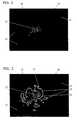
- FIG. 1aA possible arrangement of a surgical microscope is shown schematically in FIG FIG. 1a shown.
- the operating region 20is illuminated by an excitation device 1 with UV radiation, which lies in the wavelength range of about 400 nm and thus in the blue visible wavelength range.
- the fluorescence-exciting UV radiationcan originate, for example, from a xenon light source provided with filters or from a laser.
- the 5-aminolevulinic acidsynthesizes to protoporphyrin IX, which has fluorescent properties and which accumulates selectively in pathologically altered cells.
- the fluorescence spectrum of FIG. 1bshows an excitation line 5 of the fluorescence-exciting UV radiation of the excitation device 1 at about 400 nm, an emission line 6 of the radiated radiation of the fluorescent protoporphyrin IX in the visible spectral range of about 600 nm to 700 nm.
- the tumor tissue 22fluoresces and emits red light according to the emission line. 6 in the visible spectral range, the intensity of the emitted light being correlated with the concentration of intracellular protoporphyrin IX.
- An image detection device 2collects and bundles the emitted light by means of optical components on a detector, which digital image information in the form of a fluorescent image 10, which from the operating area 20 is generated.
- the actual detection in the image detection device 2can be carried out by a digital CCD camera or by a fluorescence spectrometer.
- the image detection device 2records different brightness values of the red component R, the green component G and the blue component B for each pixel. If an 8-bit sensor is selected, 256 different brightness values can be recorded. If a 16-bit sensor is selected, 65536 different brightness values can be recorded and forwarded as a digital fluorescence image 10 directly to a display device 4 and displayed there.
- the display device 4may be an eyepiece or binocular, a monitor or the like. The surgeon observes the entire procedure with the aid of the presentation device 4.
- the digital fluorescent image 10is also forwarded to the image processing system 3.
- the image processing system 3comprises a computer unit with at least one read / write memory and one Computer program which carries out the evaluation and processing of the fluorescence images and accomplishes the output of generated line profile images 11 and generated false color images 12 and the superposition of the fluorescence image 10 with the generated images.
- the first evaluation step of the image processing system 3is an extraction of the red channel from the recorded fluorescence image 10.
- the fluorescence image 10has different areas with different high light intensity in the red spectral range.
- the image processing system 3 or the operatordetermines the area in the fluorescence image 10 with a maximum intensity 26.
- the image processing system 3is capable of determining the maximum intensity 26 by comparing the intensities of all the pixels of the red component of the fluorescence image 10 and storing it as the maximum intensity.
- an input devicefor example a computer mouse, is connected to the image processing system 3, with which the surgeon selects the brightest region of pixels in the fluorescence image 10 in his opinion.
- the manual determination of the maximum intensity 26 by the surgeonprevents possible image errors in the fluorescence image 10 from being interpreted as maximum intensity 26 by the automatic determination. So that a color vision deficiency of the surgeon does not lead to problems in the manual determination of the maximum intensity 26, it is advantageous that the interesting red channel of the fluorescent image 10 is converted by known means in a gray scale image before the maximum intensity 26 is determined in the brightest region.
- a threshold value of the intensityis defined by the image processing system 3, which represents a fraction of the maximum intensity 26.
- the threshold valuerepresents the intensity of the detected fluorescence radiation, which lies between the intensity of normal tissue 21 and tumor tissue 22.
- a threshold in the range of 30% of the maximum intensity 26characterizes the threshold between healthy normal tissue 21 and tumor tissue 22 quite accurately.
- the desired threshold valuecan be stored in the image processing system 3 and, if necessary, can also be changed. Clinical trials and evaluations of already performed operations with regard to the recurrence of tumor tissue 22 have confirmed a threshold value of 33% of the maximum intensity 26 to be particularly advantageous.
- a binary imageis created, whereby pixels of the R channel of the fluorescence image 10 with intensities below the threshold value and pixels with intensities above the threshold value are distinguished.
- the boundaries between the regions having intensities greater than the threshold and regions having intensities less than the thresholdare determined and emphasized by conventional digital image processing techniques.
- morphological basic operations of image processingfor example by dilatation and / or erosion with a structuring element, for example in the form of a 3x3 matrix of ones, the boundaries between different image areas are determined.
- combinations and multiple applications of dilation and erosionmake sense, such as opening and closing, which detects edges.
- the width of the limit intensity line 25is variable and is determined inter alia by the structuring element, which is part of the morphological operators.
- the width of the boundary intensity lines 25may be varied if the structuring element is defined differently in the image processing system 3 accordingly.
- Other operations, such as high pass filtering or the gradient operator,are also applicable to generate the boundary intensity lines 25.
- the boundary intensity line 25is self-contained and encloses a tumor tissue area 27 in which pixels with a higher intensity than the defined threshold value are located.
- the pixels in the tumor tissue areas 27 with intensities greater than the thresholdcharacterize tumor tissue 22. Outside the enclosed limit intensity line 25, the pixels have intensities which are below the threshold value, whereby the tissue in the area of these pixels is defined as normal tissue 21 and the area normal tissue area 23 is called.
- the image processing system 3creates from the limit intensity lines 25 a line profile image 11 which can be superimposed on the recorded fluorescence image 10 and can be displayed by the display device 4.
- FIG. 3shows a Fluorescent image 10, which is a line profile image 11 according to FIG. 5 comprising a plurality of areas, which are surrounded by a respective closed boundary intensity line 25, is superimposed.
- the generated line profile images 11may also be separate, as in FIG FIG. 5 shown without superposition on the fluorescence image 10, or as a false color image 12, as in FIG. 6 shown and evaluated by the surgeon and selected to support the operation.
- the contour lines 24surround regions in the fluorescence image 10 whose intensities have a fixed, defined distance from the defined threshold value. For example, intensity differences of 10% between the threshold and Maximum intensity 26 can be selected.
- the contour lines 24are in the line profile image 11 of FIG. 5 shown. In order to distinguish the different contour lines 24, the contour lines 24 can be represented differently by the presentation device 4, for example by dashed lines or dots.
- Each contour line 24encloses an area of pixels whose intensity is in a certain ratio to the threshold value. It may be desirable that the contour lines 24 surround normal tissue areas 23 and / or tumor tissue areas 27 with intensities above the threshold value up to the maximum intensity.
- these additional contour lines 24are drawn in, with the tumor tissue areas 27 surrounding the contour lines 24 being colored differently in order to clarify the regions of the fluorescence image 10 which radiate with different intensities.
- the determination of the limit intensity lines 25, the contour lines 24, as well as the coloring of the differently fluorescing areas,are carried out by the image processing system 3.
- the surgeoncan optionally display the fluorescence image 10 with a superimposed line profile image 11 or false color image 12, or the line profile image 11 or the false color image 12 with the fluorescence image 10 hidden.
- the described method for the quantified, objective and reproducible determination of the boundaries of tumor tissue 22has been developed.
- the determination of the threshold valuecan either take place by the surgeon or be defined by the image processing system 3.
- fluorescence images 10are continuously recorded and the various regions are analyzed on the basis of the initially determined maximum intensity 26 and the threshold value, and the limit intensity lines 25 and the contour lines 24 are constantly recalculated and displayed.
- the tumor tissue areas 27, which are bordered by borderline intensity lines 25,are reduced in area in the course of the operation by the tumor tissue 22 being completely resected.
- all tissue classified as tumor tissueis removed and the operation is terminated.
Landscapes
- Engineering & Computer Science (AREA)
- Physics & Mathematics (AREA)
- Health & Medical Sciences (AREA)
- Life Sciences & Earth Sciences (AREA)
- General Physics & Mathematics (AREA)
- General Health & Medical Sciences (AREA)
- Surgery (AREA)
- Medical Informatics (AREA)
- Optics & Photonics (AREA)
- Theoretical Computer Science (AREA)
- Computer Vision & Pattern Recognition (AREA)
- Analytical Chemistry (AREA)
- Veterinary Medicine (AREA)
- Molecular Biology (AREA)
- Heart & Thoracic Surgery (AREA)
- Animal Behavior & Ethology (AREA)
- Pathology (AREA)
- Public Health (AREA)
- Chemical & Material Sciences (AREA)
- Nuclear Medicine, Radiotherapy & Molecular Imaging (AREA)
- Radiology & Medical Imaging (AREA)
- Biophysics (AREA)
- Biomedical Technology (AREA)
- Quality & Reliability (AREA)
- Investigating, Analyzing Materials By Fluorescence Or Luminescence (AREA)
- Image Analysis (AREA)
- Image Processing (AREA)
Abstract
Description
Translated fromGermanDie vorliegende Erfindung beschreibt ein Verfahren zur Analyse und Bearbeitung von Fluoreszenzbildern eines medizinischen Operationsmikroskops.The present invention describes a method for analyzing and processing fluorescence images of a medical surgical microscope.
Schon seit längerer Zeit wird in der Medizin die Fluoreszenz von Tumorgewebe, welche durch die Anreicherung des Tumorgewebes mit speziellen Kontrastmitteln und durch anschliessende Beleuchtung mit UV-Licht erreicht wird, beispielsweise zur Unterstützung von Resektionen von Gewebeteilen im Operationssaal genutzt.For a long time, the fluorescence of tumor tissue, which is achieved by the accumulation of tumor tissue with special contrast agents and by subsequent illumination with UV light, for example, used to support resections of tissue parts in the operating room in medicine.
Bei dieser, als intraoperativer Fluoreszenzdetektion bezeichneten Methode, wird einem Patienten beispielsweise mit einem Glioblastom vor der Hirntumoroperation eine natürliche, körpereigene Substanz (5-Aminolävulinsäure oder kurz 5-ALA) verabreicht. 5-ALA, das im Rahmen der Bildung des Blutfarbstoffes (Hämoglobin) im Körper entsteht und für die Blutbildung unerlässlich ist, hat die Eigenschaft in bösartigem Hirntumorgewebe in den Farbstoff Protoporphyrin IX umgewandelt zu werden. Das Protoporphyrin IX häuft sich in neoplastischen Zellen und damit besonders in Tumorgewebe an. Protoporphyrin IX zeigt eine typische Fluoreszenz bei einer Wellenlänge von etwa 635 nm, wenn es mit UV-Licht bestrahlt wird. Die Protoporphyrin IX Moleküle absorbieren das anregende UV-Licht und strahlen ein langwelligeres energieärmeres Fluoreszenzlicht ab, so dass das Tumorgewebe rot leuchtet.In this method, referred to as intraoperative fluorescence detection, a patient, for example, with a glioblastoma before brain tumor surgery, a natural, endogenous substance (5-aminolevulinic or short 5-ALA) administered. 5-ALA, which is formed during the formation of the blood pigment (hemoglobin) in the body and is essential for the formation of blood, has the property of being transformed into the pigment protoporphyrin IX in malignant brain tumor tissue. The protoporphyrin IX accumulates in neoplastic cells and thus especially in tumor tissue. Protoporphyrin IX exhibits a typical fluorescence at a wavelength of about 635 nm when irradiated with UV light. The protoporphyrin IX molecules absorb the stimulating UV light and emit a longer-wavelength, low-energy fluorescent light so that the tumor tissue shines red.
Da der zu entfernende Tumor häufig einen breiten Zellsaum aufweist, welcher das Normalgewebe infiltriert, oder Tumorzellansammlungen von Normalgewebe umgeben sind, ist es schwierig, nur die Tumorzellen bei minimaler Schädigung des Normalgewebes zu entfernen. Der Operateur sieht zwar im Fluoreszenzbild eine RotFluoreszenz, muss aber eigenständig beurteilen, wie viel Gewebe wegzunehmen ist.Since the tumor to be removed often has a broad cell space, which infiltrates the normal tissue, or tumor cell collections are surrounded by normal tissue, it is difficult to remove only the Remove tumor cells with minimal damage to the normal tissue. Although the surgeon sees a red fluorescence in the fluorescence image, he has to independently assess how much tissue has to be removed.
Vor allem im Bereich der Gehirnchirurgie, beispielsweise bei der Resektion von Gliomen ist es vom Operateur gewünscht, das Tumorgewebe möglichst vollständig zu resezieren, und gleichzeitig möglichst wenig bis kein Normalgewebe zu beschädigen, damit zusätzliche neurologische Störungen vermieden werden können. Mit den bislang bekannten Methoden ist eine optimierte Resektion, welche auf einer objektiven Bestimmung der Tumorgrenzen basiert, nicht möglich.Especially in the field of brain surgery, for example, in the resection of gliomas, it is desired by the surgeon to resect the tumor tissue as completely as possible, and at the same time as little as possible to damage normal tissue, so that additional neurological disorders can be avoided. Optimized resection, which is based on an objective determination of the tumor boundaries, is not possible with the methods known hitherto.
Es sind Operationsmikroskope bekannt, welche als Hilfsmittel bei der Operation eingesetzt werden und dem Operateur eine vergrösserte Abbildung des interessierenden Körperbereiches des Patienten zeigen und weitere unterstützende Merkmale aufweisen.Surgical microscopes are known, which are used as aids in the operation and show the surgeon an enlarged image of the body region of interest of the patient and have further supporting features.
In der
Der Operateur sieht durch die Projektion das Realbild des Operationsfeldes, welchem ein generiertes Bild überlagert ist, in welchem beispielsweise Normalgewebe grün eingefärbt erscheint, oder erkranktes Gewebe durch eine höhere Intensität markiert ist. Diese Zusatzinformationen werden im Bildverarbeitungssystem offline generiert.The surgeon sees through the projection of the real image of the surgical field, which is superimposed on a generated image in which, for example, normal tissue appears colored green, or diseased tissue is marked by a higher intensity. This additional information is generated offline in the image processing system.
Das oben erwähnte Dokument beschreibt zwar die photodynamische Diagnose von Tumorgewebe anhand der Anregung von Fluoreszenzstrahlung, es wird aber nicht offenbart, wie und ob das Bildverarbeitungssystem die zu entfernenden Gewebeteile analysieren kann, oder die Schnittlinien bestimmen und darstellen kann, damit der Operateur die Resektion durch Zusatzinformationen unterstützt durchführen kann.Although the above-mentioned document describes the photodynamic diagnosis of tumor tissue by excitation of fluorescence radiation, it is not disclosed how and if the image processing system can analyze the tissue to be removed, or determine and display the cut lines to allow the surgeon to resect with additional information can perform supported.
Der Schwerpunkt der Offenbarung der
Um die Zeit bis zum Wiederauftreten von Rezidivtumoren zu verlängern ist es unbedingt erforderlich möglichst alle Tumorzellen zu entfernen.In order to prolong the time until the recurrence of recurrent tumors, it is essential to remove as far as possible all tumor cells.
Da die Farbwahrnehmung von Operateur zu Operateur unterschiedlich ist und das subjektive Befinden eines Fluoreszenzbildes von der Umgebung und Beleuchtung im Operationssaal abhängt, ist bisher keine objektive Bestimmung von Tumorgrenzen, welche vom Operateur unabhängig ist, offenbart.Since the perception of color differs from surgeon to surgeon, and the subjective condition of a fluorescence image depends on the environment and lighting in the operating theater, no objective determination of tumor boundaries that is independent of the surgeon has hitherto been disclosed.
Ein aus der Druckschrift
Die vorliegende Erfindung hat sich zur Aufgabe gestellt ein Verfahren zu schaffen, welches eine quantifizierbare objektive und reproduzierbare Bestimmung der Grenzen von Tumorgewebe erlaubt, sodass die subjektive Wahrnehmung sowie die Erfahrung des Operateurs keine Rolle spielt.It is an object of the present invention to provide a method which permits a quantifiable, objective and reproducible determination of the boundaries of tumor tissue so that the subjective perception as well as the experience of the surgeon are irrelevant.
Diese Aufgabe und die damit verbundene Unterstützung der Resektion von Tumorgewebe, wodurch nur ein minimaler Teil des an den Tumor angrenzenden Normalgewebes entfernt wird und damit zusätzliche neurologische Störungen weitgehend vermieden werden können, löst das erfindungsgemässe Verfahren.This task and the related support of the resection of tumor tissue, whereby only a minimal part of the normal tissue adjacent to the tumor is removed and thus additional neurological disorders can be largely avoided, solves the inventive method.
Eine weitere Aufgabe des Erfindungsgegenstandes liegt in der Verbesserung der Lebensqualität und der Steigerung der Lebenserwartung der Patienten durch die erreichbare nahezu vollständige Tumorentfernung.Another object of the subject invention is to improve the quality of life and increase the life expectancy of patients by the achievable almost complete tumor removal.
Ein bevorzugtes Ausführungsbeispiel des Erfindungsgegenstandes wird nachstehend im Zusammenhang mit den anliegenden Zeichnungen beschrieben.
- Figur 1a
- zeigt eine schematische Darstellung eines Fluoreszenzmikroskops, welches als Operationsmikroskop eingesetzt wird, während
- Figur 1b
- ein Fluoreszenzspektrum zeigt, wobei die Intensität der Strahlung gegen die Wellenlänge aufgetragen ist und die Fluoreszenzanregung sichtbar ist.
Figur 2- zeigt ein Fluoreszenzbild eines beleuchteten und reflektierenden Operationsbereiches, während
Figur 3- ein Fluoreszenzbild des beleuchteten Operationsbereiches der
Figur 2 Figur 4- zeigt ein Fluoreszenzbild
entsprechend Figur 3 , wobei Bereiche weiterer Intensitäten durch zusätzlich Konturlinien abgegrenzt sind, während Figur 5- einen reinen Konturplot der Grenzintensitätslinie (durchgehend schwarz) und der zusätzlichen Konturlinien darstellt, welcher mit dem Bildverarbeitungssystem erzeugt wurde.
Figur 6- zeigt ein Falschfarbenbild des Operationsbereiches mit unterschiedlichen Konturlinien und unterschiedlich eingefärbten Bereichen.
- FIG. 1a
- shows a schematic representation of a fluorescence microscope, which is used as a surgical microscope, while
- FIG. 1b
- shows a fluorescence spectrum, wherein the intensity of the radiation is plotted against the wavelength and the fluorescence excitation is visible.
- FIG. 2
- shows a fluorescence image of an illuminated and reflective surgical area while
- FIG. 3
- a fluorescence image of the illuminated operating area of
FIG. 2 with superimposed critical limit intensity lines. - FIG. 4
- shows a fluorescence image accordingly
FIG. 3 , where areas of further intensities are delimited by additional contour lines, while - FIG. 5
- represents a pure contour plot of the boundary intensity line (solid black) and the additional contour lines generated with the image processing system.
- FIG. 6
- shows a false-color image of the surgical area with different contour lines and differently colored areas.
Nachdem einem Gliom-Patienten eine Substanz zur Generierung eines Tumorerkennungsmerkmales, bevorzugt 5-Aminolävulinsäure zur Generierung einer Protoporphyrin-fluoreszenz oral verabreicht wurde, der Patient für die Operation vorbereitet, anästhesiert und ein zu operierender Operationsbereich 20 zugänglich gemacht worden ist, findet die Resektion von Tumorgewebe 22 unter Verwendung eines Operationsmikroskops statt.After a glioma patient has been orally administered a substance for generating a tumor recognition feature, preferably 5-aminolevulinic acid for generating a protoporphyrin fluorescence, the patient has been prepared for surgery, anesthetized and an
Eine mögliche Anordnung eines Operationsmikroskops ist schematisch in
Das Fluoreszenzspektrum der
Eine Bilddetektionseinrichtung 2 sammelt und bündelt das emittierte Licht mittels optischer Komponenten auf einem Detektor, welcher digitale Bildinformationen in Form eines Fluoreszenzbildes 10, welches vom Operationsbereich 20 ausgesandt wird, erzeugt. Die eigentliche Detektion in der Bilddetektionseinrichtung 2 kann von einer digitalen CCD-Kamera oder von einem Fluoreszenzspektrometer durchgeführt werden.An
Durch die Detektion der emittierenden Strahlung mit einer CCD-Kamera, welche die Intensitäten des Rotanteils R, des Grünanteils G und des Blauanteils B einzeln detektiert, sind im Falle der Emissionslinie 6 im Bereich oberhalb von 600 nm keine zusätzlichen Filter mehr notwendig, um optimale Messergebnisse zu erhalten. Der grosse Abstand zwischen der Anregungslinie 5 und der Emissionslinie 6 ist also bei Verwendung einer CCD-Kamera vorteilhaft, da die Emissionslinie 6 nur innerhalb des Rotanteils R liegt und damit die Detektion nicht von der blauen Anregungslinie 5 im Blauanteil B gestört wird. Desweiteren ist die Quanteneffektivität der meissten CCD-Sensoren im Bereich des roten Lichtes am grössten, womit also die höchste Sensitvität einer CCD-Kamera im Rotbereich liegt.By detecting the emitting radiation with a CCD camera, which detects the intensities of the red component R, the green component G and the blue component B individually, in the case of the
Die Bilddetektionseinrichtung 2 nimmt für jeden Bildpunkt verschiedene Helligkeitswerte des Rotanteils R, des Grünanteils G und des Blauanteils B auf. Wird ein 8 Bit Sensor gewählt, können 256 verschiedene Helligkeitswerte aufgenommen werden. Wird ein 16 Bit Sensor gewählt, können 65536 verschiedene Helligkeitswerte aufgenommen werden und als digitales Fluoreszenzbild 10 direkt an eine Darstellungseinrichtung 4 weitergeleitet und dort dargestellt werden. Die Darstellungseinrichtung 4 kann ein Okular oder Binokular, ein Monitor oder ähnliches sein. Der Operateur beobachtet den gesamten Eingriff mit Hilfe der Darstellungseinrichtung 4.The
Zusätzlich wird das digitale Fluoreszenzbild 10 auch an das Bildverarbeitunngssystem 3 weitergeleitet. Das Bildverarbeitungssystem 3 umfasst eine Rechnereinheit mit mindestens einem Schreib-/Lesespeicher und einem Computerprogramm, welches die Auswertung und die Verarbeitung der Fluoreszenzbilder ausführt und die Ausgabe von generierten Linienprofilbildern 11 und generierten Falschfarbenbildern 12 und die Überlagerung des Fluoreszenzbildes 10 mit den generierten Bildern bewerkstelligt.In addition, the digital
Da die Fluoreszenz im roten Spektralbereich liegt und das mit Protoporphyrin IX angereicherte Tumorgewebe 22 rot leuchtet, erfolgt eine Auswertung und Verarbeitung des Rotanteils R des Fluoreszenzbildes 10, um eine quantitative Bestimmung der Ausmasse und der Grenzen des Tumorgewebes 22 zu erreichen. Der erste Auswertungsschritt des Bildverarbeitungssystems 3 ist eine Extraktion des Rot-Kanals aus dem aufgenommenen Fluoreszenzbild 10.Since the fluorescence is in the red spectral range and the
Das Fluoreszenzbild 10 weist verschiedene Bereiche mit unterschiedlich hoher Lichtintensität im roten Spektralbereich auf. Wahlweise bestimmt das Bildverarbeitungssystem 3 oder der Operateur den Bereich im Fluoreszenzbild 10 mit einer Maximalintensität 26.
Das Bildverarbeitungssystem 3 ist in der Lage die Maximalintensität 26 durch Vergleich der Intensitäten aller Pixel des Rotanteils des Fluoreszenzbildes 10 zu ermitteln und als Maximalintensität zu speichern. Für die manuelle Bestimmung der Maximalintensität 26 ist eine Eingabevorrichtung, beispielsweise eine Computermaus, mit dem Bildverarbeitungssystem 3 verbunden, mit welcher der Operateur den seiner Meinung nach hellsten Bereich von Pixeln im Fluoreszenzbild 10 wählt. Während eine automatische Bestimmung der Maximalintensität 26 reproduzierbar immer die tatsächlich höchsten Intensitätswerte als Maximalintensität 26 bestimmt, verhindert die manuelle Bestimmung der Maximalintensität 26 durch den Operateur, dass mögliche Bildfehler im Fluoreszenzbild 10 durch die automatische Bestimmung als Maximalintensität 26 interpretiert werden. Damit eine Farbenfehlsichtigkeit des Operateurs nicht zu Problemen bei der manuellen Bestimmung der Maximalintensität 26 führt, ist es vorteilhaft, dass der interessierende Rotkanal des Fluoreszenzbildes 10 mit bekannten Mitteln in ein Graustufenbild umgewandelt wird, bevor die Maximalintensität 26 im hellsten Bereich bestimmt wird.The
The
In einem nächsten Schritt wird ein Schwellwert der Intensität vom Bildverarbeitungssystem 3 definiert, welcher einen Bruchteil der Maximalintensität 26 darstellt. Der Schwellwert stellt die Intensität der detektierten Fluoreszenz-Strahlung dar, welche zwischen der Intensität von Normalgewebe 21 und Tumorgewebe 22 liegt. Wie Versuche gezeigt haben, charakterisiert ein Schwellwert im Bereich von 30% der Maximalintensität 26 die Schwelle zwischen gesundem Normalgewebe 21 und Tumorgewebe 22 ziemlich genau.In a next step, a threshold value of the intensity is defined by the
Flächen mit Pixeln im Fluoreszenzbild 10, welche eine Intensität oberhalb dieses Schwellwertes aufweisen, kennzeichnen Tumorgewebe 22, während Gewebe, welches Licht mit Intensitäten unterhalb des Schwellwertes abstrahlt und als Fläche im Fluoreszenzbild 10 sichtbar ist, als Normalgewebe 21 eingestuft wird. Der gewünschte Schwellwert kann im Bildverarbeitungssystem 3 hinterlegt werden und kann falls nötig auch verändert werden. Klinische Versuche und Auswertungen bereits durchgeführter Operationen im Hinblick auf das Wiederauftreten von Tumorgewebe 22 haben einen Schwellwert von 33% der Maximalintensität 26 als besonders vorteilhaft bestätigt.Areas with pixels in the
Nach Bestimmung der Maximalintensität 26 und des Schwellwertes, wird ein binäres Bild erstellt, wobei Pixel des R-Kanals des Fluoreszenzbildes 10 mit Intensitäten unterhalb des Schwellwertes und Pixel mit Intensitäten oberhalb des Schwellwertes unterschieden werden. Die Grenzen zwischen den Bereichen mit Intensitäten grösser als der Schwellwert und Bereichen mit Intensitäten kleiner als der Schwellwert werden durch übliche Verfahren der digitalen Bildverarbeitung bestimmt und hervorgehoben. Durch morphologische Basisoperationen der Bildbearbeitung, beispielsweise durch Dilatation und/oder Erosion mit einem strukturierenden Element, zum Beispiel in Form einer 3x3 Matrix aus Einsen, werden die Grenzen zwischen verschiedenen Bildbereichen bestimmt. In der Praxis sind Kombinationen und Mehrfachanwendungen der Dilatation und Erosion sinnvoll, beispielsweise Opening und Closing, wodurch Kanten detektiert werden. Durch Anwendung dieser bekannten Verfahren der digitalen Bildbearbeitung werden Bildinformationen generiert, welche die Grenze zwischen Tumorgewebe 22 und Normalgewebe 21 als mehrere Pixel breite Grenzintensitätslinie 25 beinhalten.After determining the
Die Breite der Grenzintensitätslinie 25 ist variierbar und wird unter anderem durch das strukturierende Element bestimmt, welches Bestandteil der morphologischen Operatoren ist. Die Breite der Grenzintensitätslinien 25 kann variiert werden, wenn das strukturierende Element entsprechend anders im Bildverarbeitungssystem 3 definiert wird. Es sind auch weitere Operationen, wie Tief- bzw. Hochpassfilterung oder der Gradient-Operator anwendbar, um die Grenzintensitätslinien 25 zu erzeugen.The width of the
Die Grenzintensitätslinie 25 ist in sich geschlossen und umschliesst einen Tumorgewebebereiche 27 in dem sich Pixel mit einer höheren Intensität als der definierte Schwellwert befinden. Die Pixel in den Tumorgewebebereichen 27 mit Intensitäten grösser als der Schwellwert, charakterisieren Tumorgewebe 22. Ausserhalb der umschlossenen Grenzintensitätslinie 25 weisen die Pixel Intensitäten auf, welche unterhalb des Schwellwertes liegen, womit das Gewebe im Bereich dieser Pixel als Normalgewebe 21 definiert ist und der Bereich Normalgewebebereich 23 genannt wird.The
Das Bildverarbeitungssystem 3 erstellt aus den Grenzintensitätslinien 25 ein Linienprofilbild 11 welches dem aufgenommenen Fluoreszenzbild 10 überlagert werden kann und mittels der Darstellungseinrichtung 4 darstellbar ist.
Während das digitale Fluoreszenzbild 10 direkt ohne Bearbeitung in Echtzeit durch die Darstellungseinrichtung 4 angezeigt wird, können vom Bildverarbeitungssystem 3 erzeugte Linienprofilbilder 11 und Falschfarbenbilder 12 dem Fluoreszenzbild 10 überlagert und angezeigt werden. Auch diese Überlagerung erfolgt in Echtzeit. Damit kann der Operateur in seiner gewohnten Darstellungseinrichtung 4 verarbeitete und berechnete Zusatzinformationen des Operationsbereiches 20 während der Resektion des Tumorgewebes 22 einsehen.While the
Um Operationen zu einem späteren Zeitpunkt auszuwerten und die Schwellwertbestimmung durch Studien zu optimieren, ist es vorgesehen die aufgenommenen Fluoreszenzbilder 10 und die generierten Linienprofilbilder 11 und Falschfarbenbilder 12 für Studienzwecke im Bildverarbeitungssystem 3 auf einer Festplatte oder einem anderen Festspeicher zu speichern.In order to evaluate operations at a later point in time and to optimize the threshold determination by studies, it is intended to store the recorded
Entsprechend dem oben beschriebenen Verfahren kann es gewünscht sein, dass neben den dargestellten Grenzintensitätslinien 25 zusätzliche Konturlinien 24 dargestellt werden.According to the above-described method, it may be desired that 25
Die Konturlinien 24 umgeben Bereiche im Fluoreszenzbild 10 deren Intensitäten einen festen definierten Abstand zum definierten Schwellwert haben. Dabei können beispielsweise Intensitätsunterschiede von 10% zwischen Schwellwert und Maximalintensität 26 gewählt werden. Die Konturlinien 24 sind im Linienprofilbild 11 der
Die von den Konturlinien 24 umschlossenen Bereiche, welche innerhalb eines von einer Grenzintensitätslinie 25 umschlossenen Tumorgewebebereiches 27 liegen, charakterisieren die verschieden stark fluoreszierenden Bereiche innerhalb des Tumorgewebebereiches 27. Es kann auch gewünscht sein, Normalgewebebereiche 23 ausserhalb eines durch eine Grenzintensitätslinie 25 umschlossenen Tumorgewebebereiches 22 durch eine Konturlinie 24 begrenzt darzustellen. Dies ist ebenfalls in
Auch im Falschfarbenbild (oder auch farbcodiertem Bild) 12 der
Um individuelle Fehler bei der Bestimmung des Ausmasses von Tumorgewebe 22 zu verringern, wurde das beschriebene Verfahren zur quantifizierten, objektiven und reproduzierbaren Bestimmung der Grenzen von Tumorgewebe 22 entwickelt. Die Bestimmung des Schwellwertes kann dabei entweder durch den Operateur stattfinden, oder durch das Bildverarbeitungssystem 3 definiert werden.In order to reduce individual errors in determining the extent of
Während der Operation werden kontinuierlich Fluoreszenzbilder 10 aufgenommen und die verschiedenen Bereiche anhand der zu Anfang bestimmten Maximalintensität 26 und des Schwellwertes analysiert und die Grenzintensitätslinien 25 und die Konturlinien 24 ständig neu berechnet und dargestellt. So werden die Tumorgewebebereiche 27, welche von Grenzintensitätslinien 25 umsäumt werden im Verlauf der Operation flächenmässig verkleinert, indem das Tumorgewebe 22 vollständig reseziert wird. Sobald keine Strahlung mit Intensitäten oberhalb des Schwellwertes detektiert wird, ist das gesamte als Tumorgewebe klassifizierte Gewebe entfernt und die Operation beendet.During the operation,
- 11
- Anregungseinrichtungexciter
- 22
- BilddetektionseinrichtungImage detection device
- 33
- BildverarbeitungssystemImage processing system
- 44
- Darstellungseinrichtungdisplay means
- 55
- Anregungslinieexcitation line
- 66
- Emissionslinieemission line
- 1010
- Fluoreszenzbildfluorescence image
- 1111
- LinienprofilbildLine profile image
- 1212
- FalschfarbenbildFalse color image
- 2020
- Operationsbereichoperation area
- 2121
- Normalgewebenormal tissue
- 2222
- Tumorgewebetumor tissue
- 2323
- NormalgewebebereichNormal tissue area
- 2424
- Konturlinie (sämtliche)Contour line (all)
- 2525
- Grenzintensitätslinie (speziell)Boundary intensity line (special)
- 2626
- Maximalintensität (entspricht 100% Intensität)Maximum intensity (corresponds to 100% intensity)
- 2727
- TumorgewebebereichTumor tissue area
Claims (14)
- A method for analysing and processing fluorescent images of a medical surgical microscope,characterised in that- a surgical region (20) is irradiated with UV radiation from an excitation device (1),- an image detection device (2) records a digital fluorescent image (10) and forwards it to an image processing system (3), in which- the red channel (R) is extracted from the fluorescent image (10), and then- a maximum intensity (26) is determined, and then- a threshold value is established as a percentage amount of the maximum intensity (26),- limit intensity lines (25) which surround tumour tissue regions (27) of which the pixels have intensities above the defined threshold value are determined, and then- a line profile image (11) is calculated which includes the limit intensity lines (25) of tumour tissue regions (27) and- is superimposed on the fluorescent image (10) in a display device (4), the regions not surrounded by limit intensity lines (25) being defined as normal tissue regions (23).
- The method for analysing and processing fluorescent images according to claim 1,characterised in that the threshold value is at least approximately 30 % of the maximum intensity (26).
- The method for analysing and processing fluorescent images according to claim 2,characterised in that the threshold value is 33 % of the maximum intensity (26).
- The method for analysing and processing fluorescent images according to claim 1,characterised in that the maximum intensity (26) can be determined independently and automatically by the image processing system (3).
- The method for analysing and processing fluorescent images according to claim 1,characterised in that the maximum intensity (26) can be determined manually by a surgeon using an input device connected to the image processing system (3), the brightest pixels of the fluorescent image (10) being selected manually.
- The method for analysing and processing fluorescent images according to claim 1,characterised in that the red channel (R) of the fluorescent image (10) is converted into a binary image before the limit intensity lines (25) are determined by the image processing system (3).
- The method for analysing and processing fluorescent images according to claim 6,characterised in that the limit intensity lines (25) are established by means of basic morphological operations of image processing, for example by dilatation and/or erosion with a structuring element, and represent the borders between tumour tissue (22) and normal tissue (21).
- The method for analysing and processing fluorescent images according to claim 7,characterised in that the structuring element of dilatation and/or erosion is a 3x3 matrix of ones.
- The method for analysing and processing fluorescent images according to claim 8,characterised in that the width of the limit intensity lines (25) is variable.
- The method for analysing and processing fluorescent images according to claim 6,characterised in that the limit intensity lines (25) are generated by low-pass filtering and/or high-pass filtering or by using the gradient operator.
- The method for analysing and processing fluorescent images according to claim 1,characterised in that the image processing system (3) generates closed contour lines (24) from the red channel (R) of the fluorescent image (10) which have a fixed defined distance from the defined threshold value and represent the borders between areas of different intensities above and below the threshold value.
- The method for analysing and processing fluorescent images according to claim 1,characterised in that a false-colour image (12) is displayed by the display device (4) and shows the normal tissue regions (23) and the tumour tissue regions (27) in different colours.
- The method for analysing and processing fluorescent images according to claim 12,characterised in that the superimposition of the line profile image (11) and/or of the false-colour image (12) on the fluorescent image (10) can be activated and deactivated.
- A computer program product for processing fluorescent images of a medical surgical microscope according to at least one of claims 1 to 13, said computer program product comprising program parts to carry out a method and carrying out the following steps:a) extracting the red channel (R) of the fluorescent image,b) establishing the maximum intensity (26),c) establishing a defined threshold value of the intensity as a percentage amount of the maximum intensity (26),d) generating limit intensity lines (25) which surround tumour tissue regions (27) of which the pixels have intensities above the defined threshold value by means of basic morphological operations of image processing, for example by dilatation and/or erosion with a structuring element,e) generating a line profile image (11) which includes the generated limit intensity lines (25), andf) superimposing the line profile image (11) on the fluorescent image (10) thus recorded, the regions not surrounded by limit intensity lines (25) being defined as normal tissue regions (23).
Applications Claiming Priority (1)
| Application Number | Priority Date | Filing Date | Title |
|---|---|---|---|
| CH19692007 | 2007-12-19 |
Publications (2)
| Publication Number | Publication Date |
|---|---|
| EP2074933A1 EP2074933A1 (en) | 2009-07-01 |
| EP2074933B1true EP2074933B1 (en) | 2012-05-02 |
Family
ID=39731234
Family Applications (1)
| Application Number | Title | Priority Date | Filing Date |
|---|---|---|---|
| EP08170247ANot-in-forceEP2074933B1 (en) | 2007-12-19 | 2008-11-28 | Method of analysing and processing fluorescent images |
Country Status (5)
| Country | Link |
|---|---|
| US (1) | US20090202119A1 (en) |
| EP (1) | EP2074933B1 (en) |
| JP (1) | JP2009148568A (en) |
| CN (1) | CN101461706A (en) |
| AT (1) | ATE555711T1 (en) |
Families Citing this family (42)
| Publication number | Priority date | Publication date | Assignee | Title |
|---|---|---|---|---|
| US8983581B2 (en)* | 2008-05-27 | 2015-03-17 | Massachusetts Institute Of Technology | System and method for large field of view, single cell analysis |
| JP5467632B2 (en)* | 2009-04-02 | 2014-04-09 | Sbiファーマ株式会社 | Automatic tumor identification device and automatic identification method of tumor site |
| US9155471B2 (en) | 2009-05-27 | 2015-10-13 | Lumicell, Inc'. | Methods and systems for spatially identifying abnormal cells |
| DE102010009476A1 (en)* | 2009-12-15 | 2011-06-16 | Testo Ag | Method and device for visualizing spatially resolved measurement results of properties that are not directly visible to the human eye |
| CN101770141B (en)* | 2009-12-31 | 2011-11-09 | 山西医科大学 | Fluorescence navigation system used in tumor surgery |
| WO2011106905A1 (en)* | 2010-03-02 | 2011-09-09 | 清华大学 | Parallel excitation system capable of spatial encoding and method thereof |
| JP5562683B2 (en)* | 2010-03-03 | 2014-07-30 | オリンパス株式会社 | Fluorescence observation equipment |
| JP5737899B2 (en)* | 2010-10-07 | 2015-06-17 | Hoya株式会社 | Diagnostic system |
| US9314304B2 (en) | 2010-12-08 | 2016-04-19 | Lumicell, Inc. | Methods and system for image guided cell ablation with microscopic resolution |
| JP5501210B2 (en)* | 2010-12-16 | 2014-05-21 | 富士フイルム株式会社 | Image processing device |
| DE102011002990B4 (en) | 2011-01-21 | 2014-02-27 | Carl Zeiss Meditec Ag | Visualize tissue in an operating area |
| CN103458759B (en)* | 2011-03-31 | 2015-10-14 | 奥林巴斯株式会社 | Fluorescence monitoring apparatus |
| KR20140039030A (en)* | 2011-06-29 | 2014-03-31 | 교토후고리츠다이가쿠호진 | Tumor site identification device and method |
| DE102012001854A1 (en) | 2012-02-01 | 2013-08-01 | Leica Microsystems (Schweiz) Ag | Special lighting Operations stereomicroscope |
| US9370328B2 (en) | 2012-11-29 | 2016-06-21 | University Of Washington Through Its Center For Commercialization | Methods and systems for determining tumor boundary characteristics |
| US20140221843A1 (en)* | 2013-02-02 | 2014-08-07 | The Regents Of The University Of California | Near-infrared imaging for diagnosis of sinusitis |
| AU2014236561B2 (en)* | 2013-03-14 | 2018-08-16 | Lumicell, Inc. | Medical imaging device and methods of use |
| DE102014107443A1 (en)* | 2014-05-27 | 2015-12-03 | Carl Zeiss Meditec Ag | Microscope system with depth preview |
| JP6731216B2 (en)* | 2014-10-24 | 2020-07-29 | 京都府公立大学法人 | Sample holder |
| DE102014016850B9 (en) | 2014-11-13 | 2017-07-27 | Carl Zeiss Meditec Ag | Optical system for fluorescence observation |
| WO2016091583A1 (en)* | 2014-12-08 | 2016-06-16 | Koninklijke Philips N.V. | Virtual interactive definition of volumetric shapes |
| CN114324268A (en)* | 2015-06-02 | 2022-04-12 | 国立大学法人旭川医科大学 | Observation aid device, information processing method, and program |
| JP6721939B2 (en)* | 2016-03-25 | 2020-07-15 | 株式会社松風 | Fluorescence image analyzer |
| EP3616596B1 (en)* | 2016-05-23 | 2025-04-30 | Leica Instruments (Singapore) Pte. Ltd. | MICROSCOPE AND METHOD USING PSEUDO-COLOR IMAGE DATA |
| EP3506624B1 (en) | 2016-09-28 | 2022-12-21 | Panasonic Holdings Corporation | Display system |
| DE102018204426B4 (en) | 2017-05-11 | 2024-02-29 | Carl Zeiss Meditec Ag | Microscopy system |
| DE102017117428B4 (en)* | 2017-08-01 | 2024-07-25 | Schölly Fiberoptic GmbH | Imaging method using fluorescence and associated image recording device |
| US11426075B1 (en) | 2017-08-23 | 2022-08-30 | Lumicell, Inc. | System and method for residual cancer cell detection |
| US20200405152A1 (en)* | 2018-05-31 | 2020-12-31 | Panasonic I-Pro Sensing Solutions Co., Ltd. | Camera device, image processing method, and camera system |
| CN108844934B (en)* | 2018-06-19 | 2024-03-08 | 华南理工大学 | Fluorescence detection system suitable for anaphylactic reaction tester and measurement method thereof |
| KR102148685B1 (en)* | 2018-12-26 | 2020-08-28 | 쓰리디메디비젼 주식회사 | Surgical video creation system |
| JP7660510B6 (en)* | 2018-12-31 | 2025-05-13 | ルミセル,インコーポレーテッド | Systems and methods for thresholding for residual cancer cell detection - Patents.com |
| JP2020171429A (en)* | 2019-04-09 | 2020-10-22 | 株式会社島津製作所 | Imaging device and imaging method |
| WO2020254287A1 (en)* | 2019-06-18 | 2020-12-24 | Surgvision B.V. | Luminescence imaging with refining loop based on combination of partial illuminations |
| EP4136616B1 (en)* | 2020-04-14 | 2024-11-06 | SurgVision GmbH | Verification of segmentation of luminescence images limited to analysis regions thereof |
| WO2021210189A1 (en)* | 2020-04-18 | 2021-10-21 | 有限会社マイテック | Pathogen quantum crystal solid-phase substrate and quantum crystal solid-phase fluorescence counting method |
| US11609229B2 (en)* | 2020-04-30 | 2023-03-21 | Mytech Co. Ltd. | Fluorescence counting system for quantifying viruses or antibodies on an immobilized metal substrate by using an antigen-antibody reaction |
| WO2021258069A2 (en)* | 2020-06-19 | 2021-12-23 | The General Hospital Corporation | Near-infrared autofluorescence imaging systems and methods |
| US12288325B2 (en)* | 2021-04-05 | 2025-04-29 | Nec Corporation | Tumor cell isolines |
| CN113693739B (en)* | 2021-08-27 | 2022-10-28 | 南京诺源医疗器械有限公司 | Tumor navigation correction method and device and portable fluorescent image navigation equipment |
| CN113842212B (en)* | 2021-10-09 | 2023-07-07 | 南京诺源医疗器械有限公司 | Fluorescence scattering optical tomography processing method and system |
| CN114298980A (en)* | 2021-12-09 | 2022-04-08 | 杭州海康慧影科技有限公司 | Image processing method, device and equipment |
Family Cites Families (6)
| Publication number | Priority date | Publication date | Assignee | Title |
|---|---|---|---|---|
| US5408996A (en)* | 1993-03-25 | 1995-04-25 | Salb; Jesse | System and method for localization of malignant tissue |
| US7236815B2 (en)* | 1995-03-14 | 2007-06-26 | The Board Of Regents Of The University Of Texas System | Method for probabilistically classifying tissue in vitro and in vivo using fluorescence spectroscopy |
| DE19523806C2 (en)* | 1995-06-29 | 1997-08-21 | Andreas Esser | Method for recognizing and in-situ representation of areas of a surface which have special backscattering properties and / or fluorescent properties and device for carrying out the method |
| JP4394356B2 (en)* | 2003-02-07 | 2010-01-06 | Hoya株式会社 | Electronic endoscope device |
| JP5461753B2 (en)* | 2004-07-30 | 2014-04-02 | オリンパス株式会社 | Endoscope device |
| DE202005021111U1 (en) | 2005-04-20 | 2007-04-12 | Storz Karl Gmbh & Co Kg | Combined diagnostic and therapy supporting endoscopic system, comprises image projecting device working in two different modes |
- 2008
- 2008-11-28ATAT08170247Tpatent/ATE555711T1/enactive
- 2008-11-28EPEP08170247Apatent/EP2074933B1/ennot_activeNot-in-force
- 2008-12-15USUS12/316,810patent/US20090202119A1/ennot_activeAbandoned
- 2008-12-19CNCNA2008101780927Apatent/CN101461706A/enactivePending
- 2008-12-19JPJP2008324308Apatent/JP2009148568A/ennot_activeWithdrawn
Also Published As
| Publication number | Publication date |
|---|---|
| US20090202119A1 (en) | 2009-08-13 |
| JP2009148568A (en) | 2009-07-09 |
| ATE555711T1 (en) | 2012-05-15 |
| CN101461706A (en) | 2009-06-24 |
| EP2074933A1 (en) | 2009-07-01 |
Similar Documents
| Publication | Publication Date | Title |
|---|---|---|
| EP2074933B1 (en) | Method of analysing and processing fluorescent images | |
| DE10362401B3 (en) | Microscopy system and microscopy method | |
| DE102014016850B9 (en) | Optical system for fluorescence observation | |
| DE69926120T2 (en) | PICTURE SYSTEM WITH AUTOMATIC GAIN CONTROL FOR REFLECTION AND FLUORESCENCE DOCOPY | |
| DE102008034008B4 (en) | Filter kit for the observation of fluorescence radiation in biological tissue | |
| DE10356088B4 (en) | Method and device for examining the skin | |
| EP3939488A1 (en) | Stereo-endoscope | |
| EP0861044A1 (en) | Apparatus for photodynamic diagnosis | |
| DE102011016138A1 (en) | Device for fluorescence diagnosis | |
| DE102015011429B9 (en) | Optical filter system and fluorescence observation system | |
| WO2012097924A1 (en) | System for visualizing tissue in an operation area | |
| DE102008059328A1 (en) | Resolution-enhanced microscopy | |
| DE112015006295T5 (en) | Image processing apparatus, biological observation apparatus and image processing method | |
| CN104010558A (en) | Fluorescence observation device, fluorescence observation method, and working method of fluorescence observation device | |
| DE102011122602A1 (en) | Apparatus and method for endoscopic fluorescence detection | |
| DE102012002086A1 (en) | A method of examining biological tissue and devices for examining and treating the tissue | |
| EP4601523A1 (en) | Medical imaging device and method for medical imaging | |
| DE102023103356A1 (en) | Medical multi-dye fluorescence imaging system and method | |
| WO2008113461A1 (en) | Method and device for evaluating fluorescence image records | |
| DE102009010446B4 (en) | Method and apparatus for quantifying blood flow in a tissue area | |
| EP1691673A1 (en) | Device for the imaging diagnosis of tissue | |
| DE102007034936A1 (en) | Weak fluorescent area recognizing device for recognition of pathological changes of e.g. skin, has portion of radiation defined such that intensity of radiation and intensity of fluorescence led to signals with imaging detection system | |
| DE102018124114B4 (en) | Method for finding functional brain tissue using electrical stimulation | |
| DE102023200671B3 (en) | Method for providing an image using a surgical microscope and surgical microscope | |
| DE102023120892A1 (en) | Method for automated localization of a specific tissue type during an endoscopic procedure and associated image acquisition system |
Legal Events
| Date | Code | Title | Description |
|---|---|---|---|
| PUAI | Public reference made under article 153(3) epc to a published international application that has entered the european phase | Free format text:ORIGINAL CODE: 0009012 | |
| AK | Designated contracting states | Kind code of ref document:A1 Designated state(s):AT BE BG CH CY CZ DE DK EE ES FI FR GB GR HR HU IE IS IT LI LT LU LV MC MT NL NO PL PT RO SE SI SK TR | |
| AX | Request for extension of the european patent | Extension state:AL BA MK RS | |
| 17P | Request for examination filed | Effective date:20091214 | |
| AKX | Designation fees paid | Designated state(s):AT BE BG CH CY CZ DE DK EE ES FI FR GB GR HR HU IE IS IT LI LT LU LV MC MT NL NO PL PT RO SE SI SK TR | |
| GRAP | Despatch of communication of intention to grant a patent | Free format text:ORIGINAL CODE: EPIDOSNIGR1 | |
| RIC1 | Information provided on ipc code assigned before grant | Ipc:G02B 21/00 20060101ALI20111026BHEP Ipc:G06T 7/00 20060101ALI20111026BHEP Ipc:G02B 21/16 20060101ALI20111026BHEP Ipc:A61B 1/06 20060101ALI20111026BHEP Ipc:A61B 1/04 20060101AFI20111026BHEP Ipc:A61B 5/00 20060101ALI20111026BHEP Ipc:A61B 19/00 20060101ALI20111026BHEP | |
| RIN1 | Information on inventor provided before grant (corrected) | Inventor name:HEFTI, MARTIN, DR. MED. Inventor name:LANDOLT, HANS, PROF. DR. MED. Inventor name:LOOSER, HERBERT, PROF. | |
| GRAS | Grant fee paid | Free format text:ORIGINAL CODE: EPIDOSNIGR3 | |
| GRAA | (expected) grant | Free format text:ORIGINAL CODE: 0009210 | |
| AK | Designated contracting states | Kind code of ref document:B1 Designated state(s):AT BE BG CH CY CZ DE DK EE ES FI FR GB GR HR HU IE IS IT LI LT LU LV MC MT NL NO PL PT RO SE SI SK TR | |
| REG | Reference to a national code | Ref country code:GB Ref legal event code:FG4D Free format text:NOT ENGLISH | |
| REG | Reference to a national code | Ref country code:AT Ref legal event code:REF Ref document number:555711 Country of ref document:AT Kind code of ref document:T Effective date:20120515 Ref country code:CH Ref legal event code:EP | |
| REG | Reference to a national code | Ref country code:IE Ref legal event code:FG4D Free format text:LANGUAGE OF EP DOCUMENT: GERMAN | |
| REG | Reference to a national code | Ref country code:DE Ref legal event code:R096 Ref document number:502008007114 Country of ref document:DE Effective date:20120628 | |
| REG | Reference to a national code | Ref country code:NL Ref legal event code:VDEP Effective date:20120502 | |
| REG | Reference to a national code | Ref country code:CH Ref legal event code:NV Representative=s name:SCHNEIDER FELDMANN AG PATENT- UND MARKENANWAELTE | |
| REG | Reference to a national code | Ref country code:LT Ref legal event code:MG4D Effective date:20120502 | |
| PG25 | Lapsed in a contracting state [announced via postgrant information from national office to epo] | Ref country code:NO Free format text:LAPSE BECAUSE OF FAILURE TO SUBMIT A TRANSLATION OF THE DESCRIPTION OR TO PAY THE FEE WITHIN THE PRESCRIBED TIME-LIMIT Effective date:20120802 Ref country code:LT Free format text:LAPSE BECAUSE OF FAILURE TO SUBMIT A TRANSLATION OF THE DESCRIPTION OR TO PAY THE FEE WITHIN THE PRESCRIBED TIME-LIMIT Effective date:20120502 Ref country code:IS Free format text:LAPSE BECAUSE OF FAILURE TO SUBMIT A TRANSLATION OF THE DESCRIPTION OR TO PAY THE FEE WITHIN THE PRESCRIBED TIME-LIMIT Effective date:20120902 Ref country code:FI Free format text:LAPSE BECAUSE OF FAILURE TO SUBMIT A TRANSLATION OF THE DESCRIPTION OR TO PAY THE FEE WITHIN THE PRESCRIBED TIME-LIMIT Effective date:20120502 Ref country code:SE Free format text:LAPSE BECAUSE OF FAILURE TO SUBMIT A TRANSLATION OF THE DESCRIPTION OR TO PAY THE FEE WITHIN THE PRESCRIBED TIME-LIMIT Effective date:20120502 Ref country code:CY Free format text:LAPSE BECAUSE OF FAILURE TO SUBMIT A TRANSLATION OF THE DESCRIPTION OR TO PAY THE FEE WITHIN THE PRESCRIBED TIME-LIMIT Effective date:20120502 Ref country code:PL Free format text:LAPSE BECAUSE OF FAILURE TO SUBMIT A TRANSLATION OF THE DESCRIPTION OR TO PAY THE FEE WITHIN THE PRESCRIBED TIME-LIMIT Effective date:20120502 | |
| PG25 | Lapsed in a contracting state [announced via postgrant information from national office to epo] | Ref country code:SI Free format text:LAPSE BECAUSE OF FAILURE TO SUBMIT A TRANSLATION OF THE DESCRIPTION OR TO PAY THE FEE WITHIN THE PRESCRIBED TIME-LIMIT Effective date:20120502 Ref country code:HR Free format text:LAPSE BECAUSE OF FAILURE TO SUBMIT A TRANSLATION OF THE DESCRIPTION OR TO PAY THE FEE WITHIN THE PRESCRIBED TIME-LIMIT Effective date:20120502 Ref country code:GR Free format text:LAPSE BECAUSE OF FAILURE TO SUBMIT A TRANSLATION OF THE DESCRIPTION OR TO PAY THE FEE WITHIN THE PRESCRIBED TIME-LIMIT Effective date:20120803 Ref country code:PT Free format text:LAPSE BECAUSE OF FAILURE TO SUBMIT A TRANSLATION OF THE DESCRIPTION OR TO PAY THE FEE WITHIN THE PRESCRIBED TIME-LIMIT Effective date:20120903 Ref country code:LV Free format text:LAPSE BECAUSE OF FAILURE TO SUBMIT A TRANSLATION OF THE DESCRIPTION OR TO PAY THE FEE WITHIN THE PRESCRIBED TIME-LIMIT Effective date:20120502 | |
| PG25 | Lapsed in a contracting state [announced via postgrant information from national office to epo] | Ref country code:NL Free format text:LAPSE BECAUSE OF FAILURE TO SUBMIT A TRANSLATION OF THE DESCRIPTION OR TO PAY THE FEE WITHIN THE PRESCRIBED TIME-LIMIT Effective date:20120502 Ref country code:SK Free format text:LAPSE BECAUSE OF FAILURE TO SUBMIT A TRANSLATION OF THE DESCRIPTION OR TO PAY THE FEE WITHIN THE PRESCRIBED TIME-LIMIT Effective date:20120502 Ref country code:RO Free format text:LAPSE BECAUSE OF FAILURE TO SUBMIT A TRANSLATION OF THE DESCRIPTION OR TO PAY THE FEE WITHIN THE PRESCRIBED TIME-LIMIT Effective date:20120502 Ref country code:EE Free format text:LAPSE BECAUSE OF FAILURE TO SUBMIT A TRANSLATION OF THE DESCRIPTION OR TO PAY THE FEE WITHIN THE PRESCRIBED TIME-LIMIT Effective date:20120502 Ref country code:DK Free format text:LAPSE BECAUSE OF FAILURE TO SUBMIT A TRANSLATION OF THE DESCRIPTION OR TO PAY THE FEE WITHIN THE PRESCRIBED TIME-LIMIT Effective date:20120502 Ref country code:CZ Free format text:LAPSE BECAUSE OF FAILURE TO SUBMIT A TRANSLATION OF THE DESCRIPTION OR TO PAY THE FEE WITHIN THE PRESCRIBED TIME-LIMIT Effective date:20120502 | |
| PGFP | Annual fee paid to national office [announced via postgrant information from national office to epo] | Ref country code:DE Payment date:20121128 Year of fee payment:5 | |
| PG25 | Lapsed in a contracting state [announced via postgrant information from national office to epo] | Ref country code:IT Free format text:LAPSE BECAUSE OF FAILURE TO SUBMIT A TRANSLATION OF THE DESCRIPTION OR TO PAY THE FEE WITHIN THE PRESCRIBED TIME-LIMIT Effective date:20120502 | |
| PGFP | Annual fee paid to national office [announced via postgrant information from national office to epo] | Ref country code:GB Payment date:20121128 Year of fee payment:5 | |
| PLBE | No opposition filed within time limit | Free format text:ORIGINAL CODE: 0009261 | |
| STAA | Information on the status of an ep patent application or granted ep patent | Free format text:STATUS: NO OPPOSITION FILED WITHIN TIME LIMIT | |
| PGFP | Annual fee paid to national office [announced via postgrant information from national office to epo] | Ref country code:FR Payment date:20121214 Year of fee payment:5 | |
| 26N | No opposition filed | Effective date:20130205 | |
| PGFP | Annual fee paid to national office [announced via postgrant information from national office to epo] | Ref country code:CH Payment date:20130226 Year of fee payment:5 | |
| REG | Reference to a national code | Ref country code:DE Ref legal event code:R097 Ref document number:502008007114 Country of ref document:DE Effective date:20130205 | |
| BERE | Be: lapsed | Owner name:KANTONSSPITAL AARAU A.G. Effective date:20121130 | |
| PG25 | Lapsed in a contracting state [announced via postgrant information from national office to epo] | Ref country code:BG Free format text:LAPSE BECAUSE OF FAILURE TO SUBMIT A TRANSLATION OF THE DESCRIPTION OR TO PAY THE FEE WITHIN THE PRESCRIBED TIME-LIMIT Effective date:20120802 | |
| REG | Reference to a national code | Ref country code:IE Ref legal event code:MM4A | |
| PG25 | Lapsed in a contracting state [announced via postgrant information from national office to epo] | Ref country code:BE Free format text:LAPSE BECAUSE OF NON-PAYMENT OF DUE FEES Effective date:20121130 | |
| PG25 | Lapsed in a contracting state [announced via postgrant information from national office to epo] | Ref country code:ES Free format text:LAPSE BECAUSE OF FAILURE TO SUBMIT A TRANSLATION OF THE DESCRIPTION OR TO PAY THE FEE WITHIN THE PRESCRIBED TIME-LIMIT Effective date:20120813 Ref country code:IE Free format text:LAPSE BECAUSE OF NON-PAYMENT OF DUE FEES Effective date:20121128 | |
| PG25 | Lapsed in a contracting state [announced via postgrant information from national office to epo] | Ref country code:MT Free format text:LAPSE BECAUSE OF FAILURE TO SUBMIT A TRANSLATION OF THE DESCRIPTION OR TO PAY THE FEE WITHIN THE PRESCRIBED TIME-LIMIT Effective date:20120502 | |
| PG25 | Lapsed in a contracting state [announced via postgrant information from national office to epo] | Ref country code:MC Free format text:LAPSE BECAUSE OF NON-PAYMENT OF DUE FEES Effective date:20121130 Ref country code:TR Free format text:LAPSE BECAUSE OF FAILURE TO SUBMIT A TRANSLATION OF THE DESCRIPTION OR TO PAY THE FEE WITHIN THE PRESCRIBED TIME-LIMIT Effective date:20120502 | |
| PG25 | Lapsed in a contracting state [announced via postgrant information from national office to epo] | Ref country code:LU Free format text:LAPSE BECAUSE OF NON-PAYMENT OF DUE FEES Effective date:20121128 | |
| REG | Reference to a national code | Ref country code:CH Ref legal event code:PL | |
| GBPC | Gb: european patent ceased through non-payment of renewal fee | Effective date:20131128 | |
| PG25 | Lapsed in a contracting state [announced via postgrant information from national office to epo] | Ref country code:LI Free format text:LAPSE BECAUSE OF NON-PAYMENT OF DUE FEES Effective date:20131130 Ref country code:HU Free format text:LAPSE BECAUSE OF FAILURE TO SUBMIT A TRANSLATION OF THE DESCRIPTION OR TO PAY THE FEE WITHIN THE PRESCRIBED TIME-LIMIT Effective date:20081128 Ref country code:CH Free format text:LAPSE BECAUSE OF NON-PAYMENT OF DUE FEES Effective date:20131130 | |
| REG | Reference to a national code | Ref country code:FR Ref legal event code:ST Effective date:20140731 | |
| PG25 | Lapsed in a contracting state [announced via postgrant information from national office to epo] | Ref country code:DE Free format text:LAPSE BECAUSE OF NON-PAYMENT OF DUE FEES Effective date:20140603 | |
| REG | Reference to a national code | Ref country code:DE Ref legal event code:R119 Ref document number:502008007114 Country of ref document:DE Effective date:20140603 | |
| PG25 | Lapsed in a contracting state [announced via postgrant information from national office to epo] | Ref country code:FR Free format text:LAPSE BECAUSE OF NON-PAYMENT OF DUE FEES Effective date:20131202 Ref country code:GB Free format text:LAPSE BECAUSE OF NON-PAYMENT OF DUE FEES Effective date:20131128 | |
| REG | Reference to a national code | Ref country code:AT Ref legal event code:MM01 Ref document number:555711 Country of ref document:AT Kind code of ref document:T Effective date:20131128 | |
| PG25 | Lapsed in a contracting state [announced via postgrant information from national office to epo] | Ref country code:AT Free format text:LAPSE BECAUSE OF NON-PAYMENT OF DUE FEES Effective date:20131128 |