EP2072072A1 - Method and device for micro-dosing a liquid - Google Patents
Method and device for micro-dosing a liquidDownload PDFInfo
- Publication number
- EP2072072A1 EP2072072A1EP20070024466EP07024466AEP2072072A1EP 2072072 A1EP2072072 A1EP 2072072A1EP 20070024466EP20070024466EP 20070024466EP 07024466 AEP07024466 AEP 07024466AEP 2072072 A1EP2072072 A1EP 2072072A1
- Authority
- EP
- European Patent Office
- Prior art keywords
- drive unit
- reservoir
- liquid
- piston
- rotation
- Prior art date
- Legal status (The legal status is an assumption and is not a legal conclusion. Google has not performed a legal analysis and makes no representation as to the accuracy of the status listed.)
- Granted
Links
- 239000007788liquidSubstances0.000titleclaimsdescription80
- 238000000034methodMethods0.000titleclaimsdescription32
- NOESYZHRGYRDHS-UHFFFAOYSA-NinsulinChemical compoundN1C(=O)C(NC(=O)C(CCC(N)=O)NC(=O)C(CCC(O)=O)NC(=O)C(C(C)C)NC(=O)C(NC(=O)CN)C(C)CC)CSSCC(C(NC(CO)C(=O)NC(CC(C)C)C(=O)NC(CC=2C=CC(O)=CC=2)C(=O)NC(CCC(N)=O)C(=O)NC(CC(C)C)C(=O)NC(CCC(O)=O)C(=O)NC(CC(N)=O)C(=O)NC(CC=2C=CC(O)=CC=2)C(=O)NC(CSSCC(NC(=O)C(C(C)C)NC(=O)C(CC(C)C)NC(=O)C(CC=2C=CC(O)=CC=2)NC(=O)C(CC(C)C)NC(=O)C(C)NC(=O)C(CCC(O)=O)NC(=O)C(C(C)C)NC(=O)C(CC(C)C)NC(=O)C(CC=2NC=NC=2)NC(=O)C(CO)NC(=O)CNC2=O)C(=O)NCC(=O)NC(CCC(O)=O)C(=O)NC(CCCNC(N)=N)C(=O)NCC(=O)NC(CC=3C=CC=CC=3)C(=O)NC(CC=3C=CC=CC=3)C(=O)NC(CC=3C=CC(O)=CC=3)C(=O)NC(C(C)O)C(=O)N3C(CCC3)C(=O)NC(CCCCN)C(=O)NC(C)C(O)=O)C(=O)NC(CC(N)=O)C(O)=O)=O)NC(=O)C(C(C)CC)NC(=O)C(CO)NC(=O)C(C(C)O)NC(=O)C1CSSCC2NC(=O)C(CC(C)C)NC(=O)C(NC(=O)C(CCC(N)=O)NC(=O)C(CC(N)=O)NC(=O)C(NC(=O)C(N)CC=1C=CC=CC=1)C(C)C)CC1=CN=CN1NOESYZHRGYRDHS-UHFFFAOYSA-N0.000claimsabstractdescription38
- 238000006073displacement reactionMethods0.000claimsabstractdescription23
- 102000004877InsulinHuman genes0.000claimsabstractdescription19
- 108090001061InsulinProteins0.000claimsabstractdescription19
- 229940125396insulinDrugs0.000claimsabstractdescription19
- 230000008878couplingEffects0.000claimsabstractdescription8
- 238000010168coupling processMethods0.000claimsabstractdescription8
- 238000005859coupling reactionMethods0.000claimsabstractdescription8
- 230000003213activating effectEffects0.000claimsabstractdescription7
- 239000003814drugSubstances0.000claimsdescription19
- 229940079593drugDrugs0.000claimsdescription13
- 230000000694effectsEffects0.000claimsdescription8
- 230000004913activationEffects0.000claimsdescription4
- 238000012544monitoring processMethods0.000claimsdescription3
- 238000007789sealingMethods0.000claimsdescription3
- 238000001802infusionMethods0.000abstractdescription8
- 230000007246mechanismEffects0.000description7
- 230000009467reductionEffects0.000description6
- 239000000126substanceSubstances0.000description6
- 230000005540biological transmissionEffects0.000description5
- 238000011282treatmentMethods0.000description5
- 208000037265diseases, disorders, signs and symptomsDiseases0.000description4
- 230000008901benefitEffects0.000description3
- 206010012601diabetes mellitusDiseases0.000description3
- 201000010099diseaseDiseases0.000description2
- 208000035475disorderDiseases0.000description2
- 238000005452bendingMethods0.000description1
- 230000001419dependent effectEffects0.000description1
- 230000001737promoting effectEffects0.000description1
- 238000002560therapeutic procedureMethods0.000description1
- 238000004804windingMethods0.000description1
Images

Classifications
- A—HUMAN NECESSITIES
- A61—MEDICAL OR VETERINARY SCIENCE; HYGIENE
- A61M—DEVICES FOR INTRODUCING MEDIA INTO, OR ONTO, THE BODY; DEVICES FOR TRANSDUCING BODY MEDIA OR FOR TAKING MEDIA FROM THE BODY; DEVICES FOR PRODUCING OR ENDING SLEEP OR STUPOR
- A61M5/00—Devices for bringing media into the body in a subcutaneous, intra-vascular or intramuscular way; Accessories therefor, e.g. filling or cleaning devices, arm-rests
- A61M5/14—Infusion devices, e.g. infusing by gravity; Blood infusion; Accessories therefor
- A61M5/142—Pressure infusion, e.g. using pumps
- A61M5/145—Pressure infusion, e.g. using pumps using pressurised reservoirs, e.g. pressurised by means of pistons
- A61M5/1452—Pressure infusion, e.g. using pumps using pressurised reservoirs, e.g. pressurised by means of pistons pressurised by means of pistons
- B—PERFORMING OPERATIONS; TRANSPORTING
- B65—CONVEYING; PACKING; STORING; HANDLING THIN OR FILAMENTARY MATERIAL
- B65D—CONTAINERS FOR STORAGE OR TRANSPORT OF ARTICLES OR MATERIALS, e.g. BAGS, BARRELS, BOTTLES, BOXES, CANS, CARTONS, CRATES, DRUMS, JARS, TANKS, HOPPERS, FORWARDING CONTAINERS; ACCESSORIES, CLOSURES, OR FITTINGS THEREFOR; PACKAGING ELEMENTS; PACKAGES
- B65D83/00—Containers or packages with special means for dispensing contents
- B65D83/76—Containers or packages with special means for dispensing contents for dispensing fluent contents by means of a piston
- A—HUMAN NECESSITIES
- A61—MEDICAL OR VETERINARY SCIENCE; HYGIENE
- A61M—DEVICES FOR INTRODUCING MEDIA INTO, OR ONTO, THE BODY; DEVICES FOR TRANSDUCING BODY MEDIA OR FOR TAKING MEDIA FROM THE BODY; DEVICES FOR PRODUCING OR ENDING SLEEP OR STUPOR
- A61M5/00—Devices for bringing media into the body in a subcutaneous, intra-vascular or intramuscular way; Accessories therefor, e.g. filling or cleaning devices, arm-rests
- A61M5/14—Infusion devices, e.g. infusing by gravity; Blood infusion; Accessories therefor
- A61M5/142—Pressure infusion, e.g. using pumps
- A61M5/14244—Pressure infusion, e.g. using pumps adapted to be carried by the patient, e.g. portable on the body
Definitions
- the present inventionrelates to a method of and a portable device for micro-dosing a liquid and to the use of this method and this device for dispensing a liquid drug according to the preambles of the independent claims.
- Micro-dosing of liquid substancesi.e. dosing of liquid substances in the range of micro-liters, is typically applied in the pharmaceutical and chemical industry and in particular in medical applications like e.g. the administration of liquid drugs to a patient's body.
- portable computer controlled micro dosing devicesare employed, e.g. insulin pumps, which typically contain a drug amount suitable for several days of treatment in a drug reservoir and supply the drug to the patient's body according to a predetermined daily profile via an infusion cannula.
- a disposable vial with a displacement pistonis employed as drug reservoir and a discharge of drug is accomplished by moving said piston towards the discharge end of the vial, thereby displacing liquid drug out of the vial.
- the drive motoris arranged in line with the liquid reservoir and a threaded appendix of the reservoir piston, which engages with its thread a gear wheel of the drive motor and is thereby linearly displaceable by the drive motor for pushing the piston of the reservoir, in a retracted position axially extends substantially over the entire length of the drive motor at the outer periphery thereof, resulting in a relative compact design.
- the threaded appendix at its side facing away from the gear wheel of the drive motorneeds to be supported, which causes, in the present case where a backlash free arrangement is necessary in order to ensure precise dosing, considerable friction.
- the transmission of forces into the pistonis extremely asymmetrical, resulting in a design which is prone to tilting of the piston and which furthermore promotes impreciseness caused by deformation of parts under load.
- the drive unitconsists of a drive motor with a reduction gear, both arranged in line with the reservoir.
- a threaded sleevewhich engages a gear wheel of the drive unit and is thereby linearly displaceable by the drive unit for actuating the piston of the reservoir, in a retracted position completely circumferentially surrounds the reduction gear but not the drive motor, resulting in a design where the length of the motor adds to the length of the device and the threaded bushing dictates with its outer diameter the minimum inner diameter of the reservoir.
- a first aspect of the inventionconcerns a method of micro-dosing a liquid from a liquid reservoir which is having a displacement piston arranged in its inside, e.g. a reservoir of the vial-type, by axially moving this piston within the reservoir towards the discharge end thereof, thereby displacing liquid out of said reservoir.
- the methodis preferably conducted in a manner that a time controlled dispensing of liquid results, i.e. the liquid is dispensed according to a specific profile over time, e.g. according to a pre-selected daily profile.
- micro-dosing of liquid substancesmeans a controlled dispensing of liquid substances in the range of micro-liters, as is typically applied in the pharmaceutical and chemical industry and in particular in medical applications like e.g. the administration of liquid drugs like insulin to a patient's body.
- a portable structure for receiving the liquid reservoiris provided.
- a drive unit for generating the forces for axially moving the displacement piston of the liquid reservoiris provided.
- the drive unitfeatures a first end and a second end and comprises a drive motor. By activating the drive motor, it is axially displaceable relative to the structure.
- the second end of the drive unitis coupled to the piston of the liquid reservoir and the liquid reservoir is secured to said structure so that in displacement direction of its piston it is immobile relative to the structure.
- the drive motoris activated so that the drive unit is axially moved towards the piston of said reservoir, with the effect that the piston is axially moved within the reservoir towards the discharge end thereof, thereby causing liquid to be dispensed out of the reservoir.
- micro-dosing of liquid from a vial-type reservoirBy micro-dosing of liquid from a vial-type reservoir according to this method, the individual elements required to conduct the method can be arranged in an ultra compact fashion without compromising on preciseness and reliability, thus, this method promotes the design of ultra compact portable micro-dosing devices for liquid medicaments, in particular insulin.
- the axial displacement of the drive unitis effected by rotating with the drive unit a first member having an outer thread, which first member is coupled to said drive unit.
- This outer threadengages a thread of a second member, which is integrally formed by or secured to the structure of the device in such a manner that in axial direction of the rotational axis of the first member facing away from the reservoir and rotational around said axis it is immobile relative to the structure.
- a second memberwhich provides an inner thread for engagement with the thread of the first member.
- the drive unit for dispensing liquid from the reservoiris axially displaced from a retracted position, in which its second end, which is coupled to the piston of the reservoir, is closest to the inner thread of the second member - this is typically the position when a new, completely filled reservoir is received in the structure and is coupled to the second end of the drive unit - to an extended position, in which the second end of the drive unit is furthermost from the thread of said second member - this is typically the position when the piston has fully been pushed towards the discharge end of the reservoir, i.e.
- the reservoirhas fully been emptied with the device - in such a manner that the first end of the drive unit, at least in the retracted position, is at least partly circumferentially surrounded by the inner thread of the second member.
- two areas of the inner thread of the second member, which each circumferentially extend over a certain anglee.g.
- the drive unit with its driven first member together with the second memberforms a telescopic drive mechanism having excellent force transmission properties and thus being sturdy and reliable.
- the activity of said drive unitis monitored by means of an encoder arranged at said drive unit with an associated control system, in order to establish a closed loop control of the displacement position of the drive unit relative to the structure and therefore of the amount of liquid dispensed.
- the drive motoris a rotating motor
- the absolute or relative linear displacement of the actuator the motor or directly of the drive unitmay be monitored.
- the forces exerted to the piston of the liquid reservoirare monitored with a force sensor with associated control unit in order to detect an operational disorder, like e.g. an occlusion in the liquid path downstream of the reservoir or e.g. a tilted piston, or an empty liquid reservoir.
- an operational disorderlike e.g. an occlusion in the liquid path downstream of the reservoir or e.g. a tilted piston, or an empty liquid reservoir.
- the power for operating the drive motoris supplied via one or several anti-rotation elements, which are arranged between the drive unit and the second member for preventing a rotation of the drive unit relative to the second member and to the structure.
- Thiscan be accomplished e.g. by means of wires, by so called flexprints or by sliding contacts established between components of the anti-rotation elements formed by the drive unit and components thereof formed by the second member or the structure, respectively.
- the drive motoris, according to a specific activity profile, activated by an electronic control system, for the time-controlled dispensing of liquid from the liquid reservoir.
- a liquid medicamentlike e.g. insulin
- a diseaselike e.g. diabetes
- thisis done according to a daily dispensing profile which may however differ from day to day, e.g. be different over the weekend compared to the normal working days.
- encoders and/or force sensorsare employed, these are functionally connected to the control system in order to establish a closed loop control and/or respective alarm functions.
- a second aspect of the inventionconcerns a portable device, preferably for performing the method according to the first aspect of the invention, for micro-dosing of a liquid from a liquid reservoir, which in a releasable manner is received inside the device, by axially moving a displacement piston arranged in the reservoir and thereby displacing liquid out of it.
- the reservoiris a vial containing a liquid medicament, like e.g. insulin.
- the devicecomprises a structure for receiving the liquid reservoir and a drive unit for generating the forces for axially moving the piston, with a first end and a second end and with a drive motor.
- the drive unitis axially displaceable relative to the structure by activating its drive motor.
- the drive unitcomprises coupling means for coupling it, in a releasable manner in order to be suitable for multiple use, to the piston of the liquid reservoir in order to axially move said piston in the reservoir towards an discharge opening of the reservoir upon an axial movement of the drive unit and thereby dispensing liquid.
- This concept according to the inventionallows the provision of ultra compact portable devices for micro-dosing liquid medicaments from vial-type reservoirs.
- the devicefurther comprises a rotatable first member, which defines an axis of rotation and has an external thread coaxially arranged around said axis of rotation, and a second member, which is integrally formed by or is secured to the structure of the device.
- This second memberhas a thread which engages the outer thread of the first member.
- the first memberis coupled to the drive unit at the first end thereof in such a manner that, upon activation of the drive motor of the drive unit, it is rotated around its axis of rotation, thereby axially moving itself and the drive unit relative to the second member and to the structure of the device.
- a micro dosing devicewith a well proven and sturdy mechanism for effecting the axial displacement of the drive unit is provided which furthermore is well suited for precise displacement control, e.g. by way of an encoder coupled to the drive shaft of the drive motor with an associated control.
- the thread of the second memberis an inner thread.
- the first member and the drive unitby activating the drive motor and subsequent rotation of the first member, can axially be displaced relative to the second member and the structure from a retracted position to an extended position.
- retracted positionis regarded a position in which the second end of the drive unit - the end which is supposed to be coupled to the piston of the reservoir - is closest to the inner thread of the second member, which typically is the case when a new, completely filled reservoir will be installed within the device.
- the second end of the drive unitis farthest away from the inner thread of the second member, which typically is the case when the reservoir has been emptied by means of the device.
- the second member with its inner threadat least partly circumferentially surrounds at least the first end of the drive unit.
- the drive unit with its driven first member together with the second memberforms a telescopic drive mechanism having excellent force transmission properties and thus being sturdy and reliable
- the inner thread of the second member in the retracted positionat least partly circumferentially surrounds, in the fashion described before, not only the first end of the drive unit but at least half of the length of the drive unit and preferably substantially the entire length of the drive unit.
- this memberis a sleeve-like element forming the internal thread at its inside. Out of one end of this sleeve-like element, the second end of the drive unit protrudes, in the retracted as well as in the extended position.
- the drive unit with its driven first membercan be received inside the second member to form together with the second member a compact, enclosed telescopic drive mechanism which can be provided as a module.
- sealing meanslike e.g. an O-ring, in order to prevent dirt or liquids to enter into the second member.
- the drive unitfurther comprises a reduction gear arranged between the drive motor and the first member.
- a reduction geararranged between the drive motor and the first member.
- the drive motorhas a drive shaft defining an axis of rotation.
- this axis of rotation and the axis of rotation of said first memberare coaxially aligned, further promoting a slim and compact design.
- the drive unitis equipped with an encoder with associated control means for monitoring the activity of the drive unit in order to establish a closed loop control of the displacement position of the drive unit relative to the structure and therefore of the amount of liquid dispensed.
- the drive motoris a rotating motor
- the absolute or relative linear displacementmay directly be monitored.
- the encoderitself is arranged at the second end of the drive unit, preferably at least partially arranged inside a protrusion which is, when the piston of the liquid reservoir is coupled to the second end of the drive unit, at least in part received inside said piston.
- an anti-rotation elementwhich prevents a rotation of the drive unit relative to the second member but permits axial movement of the drive unit relative to these elements.
- thishas the advantage that all mechanical parts for effecting the axial displacement of the drive unit can be encapsulated inside the second member, thereby forming a modular element.
- the power for operating said drive motoris supplied via said anti-rotation elements to said drive motor.
- Thiscan be accomplished e.g. by means of wires, by so called flexprints or by sliding contacts established between components of the anti-rotation elements.
- the devicecomprises a force sensor with associated controls to permit monitoring of the forces that in operation are exerted to the piston of the liquid reservoir.
- an operational disorderlike e.g. an occlusion in the liquid path downstream of the reservoir or e.g. a tilted piston, can be detected or an empty liquid reservoir.
- the axis of rotation of said first memberis coaxially aligned with a central axis of the piston of the liquid reservoir which in operation is received in the device.
- the devicefurther comprises computerized control means for controlling said drive unit in such a manner that a time-controlled dispensing of liquid is possible, i.e. the drive motor is activated according to a specific activity profile by an electronic control system, for the time-controlled dispensing of liquid from the liquid reservoir.
- a liquid medicamentlike e.g. insulin
- a diseaselike e.g. diabetes
- thisis done according to a daily dispensing profile which may however differ from day to day, e.g. be different over the weekend compared to the normal working days.
- encoders and/or force sensorsare employed, these are functionally connected to the control system in order to establish a closed loop control and/or respective alarm functions.
- the devicefurther comprises a liquid reservoir with a displacement piston received in its structure and coupled to the second end of the drive unit.
- this reservoircontains a liquid drug, like e.g. insulin or a liquid pain killer.
- a third aspect of the inventionconcerns the use of the method according to the first aspect of the invention or of the device according to the second aspect of the invention for dispensing of a liquid drug, in particular insulin or a liquid pain killer.
- a liquid drugin particular insulin or a liquid pain killer.
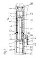
- the mechanical portion (pump section) of a micro-dosing device according to the invention in the form of a portable infusion pump for the time controlled administration of insulinis illustrated in the Figures 1a, 1b and 2 , once in longitudinal section with the pump being equipped with a new, completely filled vial 1 of insulin ( Fig. 1a ), once in longitudinal section with the pump being equipped with a used, only partially filled vial 1 of insulin ( Fig. 2 ) and onces in section along line C-C in Fig. 1a (Fig. 1b ).
- the infusion pumpcomprises a structure 3 forming the housing 16 of the pump in which a drive unit 4 and a vial 1 containing insulin are arranged in line.
- the vial 1includes a displacement piston 2 with a central axis Z, which can be axially moved inside the vial 1 towards the discharge end 18 thereof for displacing insulin out of the vial 1.
- the drive unit 4comprises a rotational electric drive motor 5 with a drive shaft (not shown) defining an axis of rotation Y and a reduction gear 13, which at its power intake side is coupled to the drive shaft of the drive motor 5 and at its power output side is coupled to a gear wheel 6 (the first member according to the claims) defining an axis of rotation X and having an outer thread 7 arranged around this axis X.
- the gear wheel 6, the gear 13 and the drive motor 5are arranged in line so that the axis X of the gear wheel 6 and the axis Y of the drive motor 5 are coaxially aligned, wherein the gear 13 is located between the gear wheel 6 and the drive motor 5.
- the end of the drive unit 4 facing away from the vial 1is formed by the reduction gear 13.
- an encoder 10is arranged inside an end portion 14 of the housing of the drive unit 4 (the second end according to the claims), which protrudes inside the displacement piston 2 of the vial 1 and thereby at the same time forms coupling means 14 according to the claims by which said piston 2 is coupled in a releasable manner to this end of the drive unit 4.
- the outer thread 7 of the gear wheel 6engages an inner thread 8 of a threaded sleeve 9 surrounding same, which sleeve 9 is secured to the structure 3 of the infusion pump in such a manner that in axial direction facing away from the vial 1 and rotationally around the axis X of the gear wheel 6 it is immobile with respect to the structure 3.
- the sleeve 9 in axial directionabuts onto a force sensor 15 arranged at the bottom of a cavity provided in the structure 3 for receiving the sleeve 9 (see Figures 1a and 2 ), while rotationally it comprises at its outer periphery a radially protruding rim 19 which engages a corresponding groove in the structure 3 (see Fig.
- the drive unit 4 at its outer peripherycomprises a finger 11, which radially extends through a longitudinal slot 20 formed in the sleeve 9 and in the structure 3, thereby forming together with the slot 20 an anti-rotating element according to the claims which prevents a rotation of the drive unit 4 relative to the sleeve 9 but permits axial travel of the drive unit 4 relative to the sleeve 9.
- the gear wheel 6is rotated by the reduction gear 13 around its axis X and thus travels with its outer thread 7 in axial direction along the inner thread 8 of the sleeve 9.
- the drive unit 4 and the displacement piston 2coupled to the end thereof and displaces them relative to the sleeve 9 and to the structure 3 and thus to the vial 1, thereby pushing the piston 2 inside the vial 1 towards the discharge end 18 thereof and dispensing insulin from the vial 1.
- Fig. 2shows a state in which the piston 2 has already travelled two thirds of its design travel way, i.e. two thirds of the rated volume of insulin of the vial 1 have already been dispensed.
- O-rings 12, 16are provided as sealing elements.
- the infusion pumpcomprises a computerised control unit (not shown) with display, user interface, power supply and control board, to which the encoder 10 and the force sensor 15 report and by which the drive unit 4 is controlled to precisely dispense insulin from the vial 1 according to a predefined daily profile.
- a computerised control unit(not shown) with display, user interface, power supply and control board, to which the encoder 10 and the force sensor 15 report and by which the drive unit 4 is controlled to precisely dispense insulin from the vial 1 according to a predefined daily profile.
- the electrical connection between the stationary and the movable electrical parts of the device, i.e. between the control unit and the drive motor 5 with the encoder 10, in this embodimentis established via a flexprint 21, which compensates the relative movement between these parts during operation.
- the flexprint 21, which provides several electrical lines,is mechanically connected with one of its ends to the free end of the finger 11, while its electrical lines are electrically connected with corresponding electrical lines which are arranged inside the finger 11 and are leading to the drive motor 5 and to the encoder 10.
- the other end of the flexprint 21is connected mechanically and electrically by means of a connector 22 to the control board (not shown).
- the flexprint 21contains eight electrical lines. Three of these lines are connected to the encoder 10, which comprises hall sensors, to control the angular position of the motor shaft. Further three lines are connected to the three motor windings (three-phased motor arrangement), one line is a power line, which in this embodiment is set to 3 volts, and the last line is a connection to ground.
- the flexprint 21is arranged directly at the drive unit 4 close to the anti-rotation element 11 and extends through the slot 20 in the sleeve 9 und in the structure 3 towards the control board or is arranged between the drive unit 4 and the sleeve 9, in the latter case enabling the inclusion of all moveable parts 4, 5, 6, 13 including the flexprint 21 inside the sleeve 9, thereby forming an enclosed telescopic drive mechanism which can be provided as a module.
Landscapes
- Health & Medical Sciences (AREA)
- Engineering & Computer Science (AREA)
- Heart & Thoracic Surgery (AREA)
- Vascular Medicine (AREA)
- Anesthesiology (AREA)
- Biomedical Technology (AREA)
- Hematology (AREA)
- Life Sciences & Earth Sciences (AREA)
- Animal Behavior & Ethology (AREA)
- General Health & Medical Sciences (AREA)
- Public Health (AREA)
- Veterinary Medicine (AREA)
- Mechanical Engineering (AREA)
- Infusion, Injection, And Reservoir Apparatuses (AREA)
Abstract
Description
- The present invention relates to a method of and a portable device for micro-dosing a liquid and to the use of this method and this device for dispensing a liquid drug according to the preambles of the independent claims.
- Micro-dosing of liquid substances, i.e. dosing of liquid substances in the range of micro-liters, is typically applied in the pharmaceutical and chemical industry and in particular in medical applications like e.g. the administration of liquid drugs to a patient's body.
- In particular in the treatment of diabetes and in certain pain treatments, in which the patient has a continuous and during the day varying demand of a medicament that can be administered subcutaneously, portable computer controlled micro dosing devices are employed, e.g. insulin pumps, which typically contain a drug amount suitable for several days of treatment in a drug reservoir and supply the drug to the patient's body according to a predetermined daily profile via an infusion cannula.
- However, specifically in the before mentioned applications where the therapy takes place in normal life, there is an increasing desire to invisibly carry the dosing device. Thus, it is of utmost importance that it is as small as possible in order not to be noticeable through the clothing when worn at the patient's body and at the same time provide a sound wearing comfort.
- The outer dimensions of today's portable micro-dosing devices for liquid drugs are mainly dictated by the space requirements of the liquid reservoir and of the drive unit of the device. Typically, as drug reservoir, a disposable vial with a displacement piston is employed and a discharge of drug is accomplished by moving said piston towards the discharge end of the vial, thereby displacing liquid drug out of the vial.
- In
US 6,248,093 B1 , several embodiments of portable micro dosing devices with different drive units and different arrangements of the reservoir and the drive unit are disclosed. However, in the embodiments where the drive motor of the drive unit is arranged beside the reservoir, an additional transmission gear is required, which causes additional costs, friction and space requirements and is furthermore prone to wear and tear. - In a further embodiment shown in
US 6,248,093 B1 , the drive motor is arranged in line with the liquid reservoir and a threaded appendix of the reservoir piston, which engages with its thread a gear wheel of the drive motor and is thereby linearly displaceable by the drive motor for pushing the piston of the reservoir, in a retracted position axially extends substantially over the entire length of the drive motor at the outer periphery thereof, resulting in a relative compact design. However, the threaded appendix at its side facing away from the gear wheel of the drive motor needs to be supported, which causes, in the present case where a backlash free arrangement is necessary in order to ensure precise dosing, considerable friction. Furthermore, the transmission of forces into the piston is extremely asymmetrical, resulting in a design which is prone to tilting of the piston and which furthermore promotes impreciseness caused by deformation of parts under load. - In yet a further embodiment shown in
US 6,248,093 B1 , the drive unit consists of a drive motor with a reduction gear, both arranged in line with the reservoir. A threaded sleeve, which engages a gear wheel of the drive unit and is thereby linearly displaceable by the drive unit for actuating the piston of the reservoir, in a retracted position completely circumferentially surrounds the reduction gear but not the drive motor, resulting in a design where the length of the motor adds to the length of the device and the threaded bushing dictates with its outer diameter the minimum inner diameter of the reservoir. Thus, even though from a mechanical point of view this design avoids the disadvantages of the before mentioned embodiments, it is unsatisfactory with respect to the length and the thickness of the device. - Hence, it is the object of the invention to provide a method of and a portable device for micro-dosing a liquid, which at least partially avoid the disadvantages of the above mentioned prior art.
- This object is achieved by the method and device according to the independent claims.
- A first aspect of the invention concerns a method of micro-dosing a liquid from a liquid reservoir which is having a displacement piston arranged in its inside, e.g. a reservoir of the vial-type, by axially moving this piston within the reservoir towards the discharge end thereof, thereby displacing liquid out of said reservoir. The method is preferably conducted in a manner that a time controlled dispensing of liquid results, i.e. the liquid is dispensed according to a specific profile over time, e.g. according to a pre-selected daily profile. As already mentioned in the introductory part, micro-dosing of liquid substances means a controlled dispensing of liquid substances in the range of micro-liters, as is typically applied in the pharmaceutical and chemical industry and in particular in medical applications like e.g. the administration of liquid drugs like insulin to a patient's body.
- In one step of the method, a portable structure for receiving the liquid reservoir is provided.
- Furthermore, a drive unit for generating the forces for axially moving the displacement piston of the liquid reservoir is provided. The drive unit features a first end and a second end and comprises a drive motor. By activating the drive motor, it is axially displaceable relative to the structure.
- In yet a further step of the method, the second end of the drive unit is coupled to the piston of the liquid reservoir and the liquid reservoir is secured to said structure so that in displacement direction of its piston it is immobile relative to the structure.
- In yet a further step of the method, the drive motor is activated so that the drive unit is axially moved towards the piston of said reservoir, with the effect that the piston is axially moved within the reservoir towards the discharge end thereof, thereby causing liquid to be dispensed out of the reservoir.
- By micro-dosing of liquid from a vial-type reservoir according to this method, the individual elements required to conduct the method can be arranged in an ultra compact fashion without compromising on preciseness and reliability, thus, this method promotes the design of ultra compact portable micro-dosing devices for liquid medicaments, in particular insulin.
- In a preferred embodiment of the method, the axial displacement of the drive unit is effected by rotating with the drive unit a first member having an outer thread, which first member is coupled to said drive unit. This outer thread engages a thread of a second member, which is integrally formed by or secured to the structure of the device in such a manner that in axial direction of the rotational axis of the first member facing away from the reservoir and rotational around said axis it is immobile relative to the structure. By this, a well proven and sturdy mechanism for effecting the axial movement of the drive unit is arrived at, which furthermore allows for sensitive displacement control, e.g. by way of a control unit with an encoder coupled to the drive shaft of the drive motor.
- In the before mentioned preferred embodiment it is furthermore preferred that a second member is employed which provides an inner thread for engagement with the thread of the first member. Furthermore, the drive unit for dispensing liquid from the reservoir is axially displaced from a retracted position, in which its second end, which is coupled to the piston of the reservoir, is closest to the inner thread of the second member - this is typically the position when a new, completely filled reservoir is received in the structure and is coupled to the second end of the drive unit - to an extended position, in which the second end of the drive unit is furthermost from the thread of said second member - this is typically the position when the piston has fully been pushed towards the discharge end of the reservoir, i.e. the reservoir has fully been emptied with the device - in such a manner that the first end of the drive unit, at least in the retracted position, is at least partly circumferentially surrounded by the inner thread of the second member. This means that at least in the retracted position at least at certain positions distributed at the circumference of the drive unit at least over an angle of more than 180° (360° is the complete circumference of the drive unit) portions of the inner thread of the second member are facing towards the drive unit. This is the case e.g. where two areas of the inner thread of the second member, which each circumferentially extend over a certain angle (e.g. 5°) of the circumference of the first end of the drive unit, are positioned opposite to each others (180°) with the first end of the drive unit arranged between them, e.g. where three areas of said inner thread are equally distributed over the circumference of the first end of the drive unit or e.g. where the inner thread consists of one area only, which covers an angle of more than 180° of circumference of the first end of the drive unit. By this, the drive unit with its driven first member together with the second member forms a telescopic drive mechanism having excellent force transmission properties and thus being sturdy and reliable.
- In yet a further preferred embodiment of the method, the activity of said drive unit is monitored by means of an encoder arranged at said drive unit with an associated control system, in order to establish a closed loop control of the displacement position of the drive unit relative to the structure and therefore of the amount of liquid dispensed. In cases where the drive motor is a rotating motor, it is preferred to monitor with the encoder the total or relative number of revolutions or a total or relative angle of rotation of the drive shaft of the motor. In cases where a linear motor is employed, the absolute or relative linear displacement of the actuator the motor or directly of the drive unit may be monitored.
- In yet a further preferred embodiment of the method, the forces exerted to the piston of the liquid reservoir are monitored with a force sensor with associated control unit in order to detect an operational disorder, like e.g. an occlusion in the liquid path downstream of the reservoir or e.g. a tilted piston, or an empty liquid reservoir.
- In yet a further preferred embodiment of the method where the before mentioned second member is employed, the power for operating the drive motor is supplied via one or several anti-rotation elements, which are arranged between the drive unit and the second member for preventing a rotation of the drive unit relative to the second member and to the structure. This can be accomplished e.g. by means of wires, by so called flexprints or by sliding contacts established between components of the anti-rotation elements formed by the drive unit and components thereof formed by the second member or the structure, respectively. By means of this, transmittal of the energy for the drive can be achieved in a simple and reliable manner.
- In yet a further preferred embodiment of the method, the drive motor is, according to a specific activity profile, activated by an electronic control system, for the time-controlled dispensing of liquid from the liquid reservoir. In the preferred application of the method for dispensing a liquid medicament, like e.g. insulin, for the treatment of a disease, like e.g. diabetes, this is done according to a daily dispensing profile which may however differ from day to day, e.g. be different over the weekend compared to the normal working days. Where, as before described, encoders and/or force sensors are employed, these are functionally connected to the control system in order to establish a closed loop control and/or respective alarm functions.
- A second aspect of the invention concerns a portable device, preferably for performing the method according to the first aspect of the invention, for micro-dosing of a liquid from a liquid reservoir, which in a releasable manner is received inside the device, by axially moving a displacement piston arranged in the reservoir and thereby displacing liquid out of it. Preferably, the reservoir is a vial containing a liquid medicament, like e.g. insulin.
- The device comprises a structure for receiving the liquid reservoir and a drive unit for generating the forces for axially moving the piston, with a first end and a second end and with a drive motor. The drive unit is axially displaceable relative to the structure by activating its drive motor. At its second end, the drive unit comprises coupling means for coupling it, in a releasable manner in order to be suitable for multiple use, to the piston of the liquid reservoir in order to axially move said piston in the reservoir towards an discharge opening of the reservoir upon an axial movement of the drive unit and thereby dispensing liquid.
- This concept according to the invention allows the provision of ultra compact portable devices for micro-dosing liquid medicaments from vial-type reservoirs.
- In a preferred embodiment, the device further comprises a rotatable first member, which defines an axis of rotation and has an external thread coaxially arranged around said axis of rotation, and a second member, which is integrally formed by or is secured to the structure of the device. This second member has a thread which engages the outer thread of the first member. The first member is coupled to the drive unit at the first end thereof in such a manner that, upon activation of the drive motor of the drive unit, it is rotated around its axis of rotation, thereby axially moving itself and the drive unit relative to the second member and to the structure of the device. By this, a micro dosing device with a well proven and sturdy mechanism for effecting the axial displacement of the drive unit is provided which furthermore is well suited for precise displacement control, e.g. by way of an encoder coupled to the drive shaft of the drive motor with an associated control.
- In the before mentioned embodiment of the device it is furthermore preferred that the thread of the second member is an inner thread. Furthermore it is preferred that the first member and the drive unit, by activating the drive motor and subsequent rotation of the first member, can axially be displaced relative to the second member and the structure from a retracted position to an extended position. As retracted position is regarded a position in which the second end of the drive unit - the end which is supposed to be coupled to the piston of the reservoir - is closest to the inner thread of the second member, which typically is the case when a new, completely filled reservoir will be installed within the device. As extended position a position is regarded in which the second end of the drive unit is farthest away from the inner thread of the second member, which typically is the case when the reservoir has been emptied by means of the device. In the retracted position, the second member with its inner thread at least partly circumferentially surrounds at least the first end of the drive unit. As already mentioned earlier, this means that in the retracted position and possibly also in further positions between the retracted and the extended position at least at certain positions distributed at the circumference of the first end of the drive unit over an angle of more than 180° (360° is the complete circumference of the drive unit), portions of the inner thread of the second member are facing towards the first end of the drive unit. This is the case e.g. where two areas of the inner thread of the second member, which each cover a certain angle of circumference of the first end of the drive unit (e.g. 5°), are positioned opposite to each others (180°) with the first end of the drive unit arranged between them, e.g. where three areas of said inner thread are equally distributed over the circumference of the first end the drive unit or e.g. where the inner thread consists of one area only which covers an angle of more than 180° of circumference of the first end of the drive unit. By this, the drive unit with its driven first member together with the second member forms a telescopic drive mechanism having excellent force transmission properties and thus being sturdy and reliable
- In the before mentioned preferred embodiment of the device it is furthermore preferred that the inner thread of the second member in the retracted position at least partly circumferentially surrounds, in the fashion described before, not only the first end of the drive unit but at least half of the length of the drive unit and preferably substantially the entire length of the drive unit. By this, the drive unit with its driven first member together with the second member forms a telescopic drive mechanism having an excellent ratio between retracted and extended length.
- In a further preferred embodiment of the device with the second member, this member is a sleeve-like element forming the internal thread at its inside. Out of one end of this sleeve-like element, the second end of the drive unit protrudes, in the retracted as well as in the extended position. By this, the drive unit with its driven first member can be received inside the second member to form together with the second member a compact, enclosed telescopic drive mechanism which can be provided as a module.
- In the before mentioned preferred embodiment it is furthermore preferred that between the end of the second member, out of which the second end of the drive unit protrudes, and the drive unit there are arranged sealing means, like e.g. an O-ring, in order to prevent dirt or liquids to enter into the second member.
- In yet a further preferred embodiment of the device with the first member, the drive unit further comprises a reduction gear arranged between the drive motor and the first member. By this, relative small motors can be employed without compromising on the torque available for rotating the first member and a sensitive displacement control becomes possible. Furthermore, in this case it is preferred that this gear forms the first end of the drive unit, thus, is physically located between the drive motor and the first member. By this, the drive unit can be designed as slim as possible.
- In yet a further preferred embodiment of the device, the drive motor has a drive shaft defining an axis of rotation. Preferably, in the embodiments mentioned earlier with the first member, this axis of rotation and the axis of rotation of said first member are coaxially aligned, further promoting a slim and compact design.
- In yet a further embodiment of the device, the drive unit is equipped with an encoder with associated control means for monitoring the activity of the drive unit in order to establish a closed loop control of the displacement position of the drive unit relative to the structure and therefore of the amount of liquid dispensed. In cases where the drive motor is a rotating motor, it is preferred to monitor with the encoder the total or relative number of revolutions or a total or relative angle of rotation, respectively, of the shaft of the motor. In cases where a linear motor is employed, the absolute or relative linear displacement may directly be monitored.
- In the before mentioned preferred embodiment it is furthermore preferred that the encoder itself is arranged at the second end of the drive unit, preferably at least partially arranged inside a protrusion which is, when the piston of the liquid reservoir is coupled to the second end of the drive unit, at least in part received inside said piston. By this, an encoder can be used without necessarily increasing the length of the device.
- In yet a further embodiment of the device with the second member, between the drive unit and the second member there is arranged an anti-rotation element which prevents a rotation of the drive unit relative to the second member but permits axial movement of the drive unit relative to these elements. In particular in embodiments where the device comprises the before mentioned second element with a sleeve-like design, this has the advantage that all mechanical parts for effecting the axial displacement of the drive unit can be encapsulated inside the second member, thereby forming a modular element.
- In the before mentioned embodiment it is furthermore preferred that the power for operating said drive motor is supplied via said anti-rotation elements to said drive motor. This can be accomplished e.g. by means of wires, by so called flexprints or by sliding contacts established between components of the anti-rotation elements. By means of this, transmittal of the energy for the drive can be achieved in a simple and reliable manner.
- In yet a further preferred embodiment, the device comprises a force sensor with associated controls to permit monitoring of the forces that in operation are exerted to the piston of the liquid reservoir. By this, an operational disorder, like e.g. an occlusion in the liquid path downstream of the reservoir or e.g. a tilted piston, can be detected or an empty liquid reservoir. In embodiments of the device with the second member, it is preferred to axially support said second member by the force sensor in order to permit determination of the forces. In other embodiments it is e.g. envisaged to include the force sensor in the coupling means of the drive unit.
- In yet a further embodiment of the device with the first member it is preferred that the axis of rotation of said first member is coaxially aligned with a central axis of the piston of the liquid reservoir which in operation is received in the device. By this, the advantage is arrived at that a fully symmetrical transmission of forces from the first member to the piston becomes possible, thus any tendency for bending and tilting of the involved components is reduced to a minimum and therewith also the friction between these parts and adjacent stationary parts when moved relative to each other.
- In yet a further preferred embodiment the device further comprises computerized control means for controlling said drive unit in such a manner that a time-controlled dispensing of liquid is possible, i.e. the drive motor is activated according to a specific activity profile by an electronic control system, for the time-controlled dispensing of liquid from the liquid reservoir. In the preferred application of the method for dispensing a liquid medicament, like e.g. insulin, for the treatment of a disease, like e.g. diabetes, this is done according to a daily dispensing profile which may however differ from day to day, e.g. be different over the weekend compared to the normal working days. Where, as described before, encoders and/or force sensors are employed, these are functionally connected to the control system in order to establish a closed loop control and/or respective alarm functions.
- In yet a further preferred embodiment, the device further comprises a liquid reservoir with a displacement piston received in its structure and coupled to the second end of the drive unit. Preferably, this reservoir contains a liquid drug, like e.g. insulin or a liquid pain killer.
- A third aspect of the invention concerns the use of the method according to the first aspect of the invention or of the device according to the second aspect of the invention for dispensing of a liquid drug, in particular insulin or a liquid pain killer. In these applications, the advantages of the invention become especially clearly apparent.
- Further preferred embodiments of the invention become apparent from the dependent claims and from the following description by way of the drawings. Therein show:
Fig. 1a a sectional view through a portion of an infusion pump according to the invention with completely filled reservoir;Fig. 1b a cut along line C-C inFig. 1a ; andFig. 2 an illustration as inFig. 1a with partially emptied reservoir.- The mechanical portion (pump section) of a micro-dosing device according to the invention in the form of a portable infusion pump for the time controlled administration of insulin is illustrated in the
Figures 1a, 1b and2 , once in longitudinal section with the pump being equipped with a new, completely filledvial 1 of insulin (Fig. 1a ), once in longitudinal section with the pump being equipped with a used, only partially filledvial 1 of insulin (Fig. 2 ) and onces in section along line C-C inFig. 1a (Fig. 1b ). As can be seen from these drawings, the infusion pump comprises astructure 3 forming thehousing 16 of the pump in which adrive unit 4 and avial 1 containing insulin are arranged in line. Thevial 1 includes adisplacement piston 2 with a central axis Z, which can be axially moved inside thevial 1 towards the discharge end 18 thereof for displacing insulin out of thevial 1. Thedrive unit 4 comprises a rotationalelectric drive motor 5 with a drive shaft (not shown) defining an axis of rotation Y and areduction gear 13, which at its power intake side is coupled to the drive shaft of thedrive motor 5 and at its power output side is coupled to a gear wheel 6 (the first member according to the claims) defining an axis of rotation X and having anouter thread 7 arranged around this axis X. Thegear wheel 6, thegear 13 and thedrive motor 5 are arranged in line so that the axis X of thegear wheel 6 and the axis Y of thedrive motor 5 are coaxially aligned, wherein thegear 13 is located between thegear wheel 6 and thedrive motor 5. By this arrangement, the end of thedrive unit 4 facing away from the vial 1 (the first end according to the claims) is formed by thereduction gear 13. At the other end of thedrive motor 5, anencoder 10 is arranged inside anend portion 14 of the housing of the drive unit 4 (the second end according to the claims), which protrudes inside thedisplacement piston 2 of thevial 1 and thereby at the same time forms coupling means 14 according to the claims by which saidpiston 2 is coupled in a releasable manner to this end of thedrive unit 4. - The
outer thread 7 of thegear wheel 6 engages aninner thread 8 of a threadedsleeve 9 surrounding same, whichsleeve 9 is secured to thestructure 3 of the infusion pump in such a manner that in axial direction facing away from thevial 1 and rotationally around the axis X of thegear wheel 6 it is immobile with respect to thestructure 3. For accomplishing this, thesleeve 9 in axial direction abuts onto aforce sensor 15 arranged at the bottom of a cavity provided in thestructure 3 for receiving the sleeve 9 (seeFigures 1a and2 ), while rotationally it comprises at its outer periphery aradially protruding rim 19 which engages a corresponding groove in the structure 3 (seeFig. 1b ). Thedrive unit 4 at its outer periphery comprises afinger 11, which radially extends through alongitudinal slot 20 formed in thesleeve 9 and in thestructure 3, thereby forming together with theslot 20 an anti-rotating element according to the claims which prevents a rotation of thedrive unit 4 relative to thesleeve 9 but permits axial travel of thedrive unit 4 relative to thesleeve 9. - As can be seen when considering the
Figures 1a and2 in combination, by activating thedrive motor 5, thegear wheel 6 is rotated by thereduction gear 13 around its axis X and thus travels with itsouter thread 7 in axial direction along theinner thread 8 of thesleeve 9. By doing so, it carries with it thedrive unit 4 and thedisplacement piston 2 coupled to the end thereof and displaces them relative to thesleeve 9 and to thestructure 3 and thus to thevial 1, thereby pushing thepiston 2 inside thevial 1 towards the discharge end 18 thereof and dispensing insulin from thevial 1.Fig. 2 shows a state in which thepiston 2 has already travelled two thirds of its design travel way, i.e. two thirds of the rated volume of insulin of thevial 1 have already been dispensed. - As becomes apparent when looking at
Fig. 1b , the end of thedrive unit 4 carrying thegear wheel 6 is, with the only exception of theslot 20 receiving thefinger 11, completely enclosed by theinner thread 8 of thesleeve 9, i.e. thisthread 8 circumferentially surrounds this end of thedrive unit 4 by nearly 360°. - As can further be taken from the
Figures 1a and2 , the before mentioned end of thedrive unit 4 carrying thegear wheel 6 in any displacement position of thedrive unit 4 remains within the threadedarea 8 of thesleeve 9, and in the fully retracted state (the retracted position according to the claims) shown inFig. 1a surrounds thedrive unit 4 with itsinner thread 8 nearly over its complete length, while merely the end portion of thedrive unit 4 which is coupled to thepiston 2 of thevial 1 protrudes out of saidsleeve 9. - In order to prevent dirt and liquid from entering the
sleeve 9 and the area between thesleeve 9 and thestructure 3, O-rings - Furthermore, the infusion pump comprises a computerised control unit (not shown) with display, user interface, power supply and control board, to which the
encoder 10 and theforce sensor 15 report and by which thedrive unit 4 is controlled to precisely dispense insulin from thevial 1 according to a predefined daily profile. - The electrical connection between the stationary and the movable electrical parts of the device, i.e. between the control unit and the
drive motor 5 with theencoder 10, in this embodiment is established via aflexprint 21, which compensates the relative movement between these parts during operation. Theflexprint 21, which provides several electrical lines, is mechanically connected with one of its ends to the free end of thefinger 11, while its electrical lines are electrically connected with corresponding electrical lines which are arranged inside thefinger 11 and are leading to thedrive motor 5 and to theencoder 10. The other end of theflexprint 21 is connected mechanically and electrically by means of aconnector 22 to the control board (not shown). - In the current case, in which a brushless DC-motor is employed, the
flexprint 21 contains eight electrical lines. Three of these lines are connected to theencoder 10, which comprises hall sensors, to control the angular position of the motor shaft. Further three lines are connected to the three motor windings (three-phased motor arrangement), one line is a power line, which in this embodiment is set to 3 volts, and the last line is a connection to ground. - In further preferred embodiments, the
flexprint 21 is arranged directly at thedrive unit 4 close to theanti-rotation element 11 and extends through theslot 20 in thesleeve 9 und in thestructure 3 towards the control board or is arranged between thedrive unit 4 and thesleeve 9, in the latter case enabling the inclusion of allmoveable parts flexprint 21 inside thesleeve 9, thereby forming an enclosed telescopic drive mechanism which can be provided as a module.
Claims (24)
- A method of micro-dosing, in particular in a time-controlled manner, a liquid from a liquid reservoir (1) by axially moving a piston (2) arranged in said reservoir (1), thereby displacing liquid out of said reservoir (1), the method comprising the following steps:a) providing a portable structure (3) for receiving the reservoir (1);b) providing a drive unit (4) with a first end and a second end and a drive motor (5), which drive unit (4) upon activation of said drive motor (5) is axially displaceable relative to said structure (3);c) connecting said drive unit (4) at its second end to said piston (2) of said liquid reservoir (1) and securing said liquid reservoir (1) to said structure (3); andd) activating said drive motor (5) to axially displace said drive unit (4) towards said piston (2) of said reservoir (1), thereby axially moving said piston (2) in said reservoir (1) and displacing liquid out of said reservoir (1).
- Method according to claim 1, wherein said axial displacement of said drive unit (4) is effected by rotating with said drive unit (4) a first member (6) coupled to said drive unit (4) at the first end of said drive unit (4) and having an outer thread (7), which engages a thread (8) of a second member (9) which is formed by or secured to said structure (3).
- Method according to claim 2, wherein said thread (8) of said second member (9) is an inner thread (8) and said drive unit (4) is axially displaced from a retracted position, in which said second end of said drive unit (4) is closest to said inner thread (8) of said second member (9), to an extended position, in which said second end of said drive unit (4) is farthest away from said inner thread (8) of said second member (9), in such a manner that said first end of said drive unit (4) at least in the retracted position is at least partly circumferentially surrounded by said inner thread (8) of said second member (9).
- Method according to one of the preceding claims, wherein the activity of said drive unit (4) is monitored by means of an encoder (10) arranged at said drive unit (4).
- Method according to one of the preceding claims, wherein the forces exerted to said piston (2) of said liquid reservoir (1) are monitored with a force sensor (15).
- Method according to one of the claims 2 to 5, wherein the power for operating said drive motor (5) is supplied to said drive motor (5) via an anti-rotation element (11) arranged between said drive unit (4) and said second member (9) for preventing a rotation of said drive unit (4) relative to said second member (9).
- Method according to one of the preceding claims, wherein said drive motor (5) is activated by an electronic control system according to a specific activity profile, for the time-controlled dispensing of liquid from the liquid reservoir.
- A portable device, in particular for performing the method according to one of the preceding claims, for micro-dosing of a liquid from a liquid reservoir (1) to be received inside the device by axially moving a piston (2) arranged in said reservoir (1) and thereby displacing liquid out of said reservoir (1), the device comprising:a) a structure (3) for receiving the reservoir (1) andb) a drive unit (4) with a first end and a second end and with a drive motor (5), which drive unit (4) is axially displaceable relative to said structure (3) by activating said drive motor (5),wherein said drive unit (4) at its second end comprises coupling means (14) for coupling it in a releasable manner to said piston (2) of said liquid reservoir (1), in order to axially move said piston (2) in said reservoir (1) upon an axial movement of said drive unit (4).
- The device according to claim 8, further comprising:b) a rotatable first member (6) defining an axis of rotation (X) and having an external thread (7) coaxially arranged around said axis of rotation (X);
andc) a second member (9) formed by or secured to said structure (3) of said device, having a thread (8) which engages said outer thread (7) of said first member (6);wherein said first member (6) is coupled to said drive unit (4) at the first end of said drive unit (4) in such a manner that, upon activation of said drive unit (4), said first member (6) is rotated by said drive unit (4) around its axis of rotation (X), thereby axially displacing said first member (6) and said drive unit (4) relative to said second member (9) and to said structure (3). - The device according to claim 9, wherein said thread (8) of said second member (9) is an inner thread (8) and wherein said first member (6) and said drive unit (4), upon activation of said drive unit (4) and subsequent rotation of said first member (6) around its axis of rotation (X), can axially be displaced relative to said second member (9) from a retracted position, in which said second end of said drive unit (4) is closest to said inner thread (8) of said second member (9), to an extended position, in which said second end of said drive unit (4) is farthest away from said inner thread (8) of said second member (9), and wherein in said retracted position said second member (9) with its inner thread (8) at least partly circumferentially surrounds at least said first end of said drive unit (4).
- The device according to claim 10, wherein in said retracted position more than half of the length of said drive unit (4) is at least partly circumferentially surrounded by said inner thread (8) of said second member (9).
- The device according to one of the claims 10 to 11, wherein said second member (9) is a sleeve-like element with said internal thread (8) at its inside, out of which at one end thereof said second end of said drive unit (4) protrudes.
- The device according to claim 12, wherein at said end of said second member (9), out of which said second end of said drive unit (4) protrudes, between said second member (9) and said drive unit (4) there are arranged sealing means (12) in order to prevent dirt or liquids to enter said second member (9).
- The device according to one of the claims 9 to 13, wherein said drive unit (4) further comprises a gear (13) arranged between said drive motor (5) and said first member (6), and in particular, wherein said gear (13) forms said first end of said drive unit (4).
- The device according to one of the claims 9 to 14, wherein said drive motor (5) has a drive shaft defining an axis of rotation (Y) and wherein this axis of rotation (Y) of said drive shaft and said axis of rotation (X) of said first member (6) are coaxially aligned.
- The device according to one of the claims 8 to 15, wherein said drive unit (4) comprises an encoder (10) for monitoring the activity of said drive unit (4).
- The device according to claim 16, wherein said encoder (10) is arranged at said second end of said drive unit (4), and in particular, wherein said encoder (10) is at least partially arranged inside a protrusion (14) which in operation is at least in part received in said piston (2) of said liquid reservoir (1).
- The device according to one of the claims 9 to 17, wherein between said drive unit (4) and said second member (9) there is arranged an anti-rotation element (11) which prevents a rotation of said drive unit (4) relative to said second member (4) but permits axial movement of said drive unit (4) relative to said second member (9).
- The device according to claim 18, wherein the device is designed in such a manner that the power for operating said drive motor (5) is supplied via said anti-rotation elements (11) to said drive motor (5).
- The device according to one of the claims 8 to 19, wherein the device comprises a force sensor (15) in order to permit in operation determination of the forces exerted to said piston (2) of said liquid reservoir (1).
- The device according to one of the claims 9 to 20, wherein said axis of rotation (X) of said first member (6) is coaxially aligned with a central axis (Z) of said piston (2) of said liquid reservoir (1) which in operation is received in the device.
- The device according to one of the claims 8 to 21, further comprising computerized control means for controlling said drive unit (4) in such a manner that a time-controlled dispensing of liquid is possible.
- The device according to one of the claims 8 to 22, further comprising a liquid reservoir with a displacement piston.
- Use of the method and of the device according to one of the preceding claims for dispensing of a liquid drug, in particular insulin or a liquid pain killer.
Priority Applications (5)
| Application Number | Priority Date | Filing Date | Title |
|---|---|---|---|
| EP07024466.0AEP2072072B1 (en) | 2007-12-18 | 2007-12-18 | Method and device for micro-dosing a liquid |
| DK07024466.0TDK2072072T3 (en) | 2007-12-18 | 2007-12-18 | Method and apparatus for micro-dosing a liquid |
| PCT/EP2008/010626WO2009077143A1 (en) | 2007-12-18 | 2008-12-13 | Method and device for micro-dosing a liquid |
| US12/818,298US8419691B2 (en) | 2007-12-18 | 2010-06-18 | Method and device for micro-dosing a liquid |
| US13/803,070US9011390B2 (en) | 2007-12-18 | 2013-03-14 | Method and device for micro-dosing a liquid |
Applications Claiming Priority (1)
| Application Number | Priority Date | Filing Date | Title |
|---|---|---|---|
| EP07024466.0AEP2072072B1 (en) | 2007-12-18 | 2007-12-18 | Method and device for micro-dosing a liquid |
Publications (2)
| Publication Number | Publication Date |
|---|---|
| EP2072072A1true EP2072072A1 (en) | 2009-06-24 |
| EP2072072B1 EP2072072B1 (en) | 2016-08-24 |
Family
ID=39353957
Family Applications (1)
| Application Number | Title | Priority Date | Filing Date |
|---|---|---|---|
| EP07024466.0ANot-in-forceEP2072072B1 (en) | 2007-12-18 | 2007-12-18 | Method and device for micro-dosing a liquid |
Country Status (4)
| Country | Link |
|---|---|
| US (2) | US8419691B2 (en) |
| EP (1) | EP2072072B1 (en) |
| DK (1) | DK2072072T3 (en) |
| WO (1) | WO2009077143A1 (en) |
Families Citing this family (9)
| Publication number | Priority date | Publication date | Assignee | Title |
|---|---|---|---|---|
| CA2670489C (en)* | 2008-06-30 | 2017-10-24 | Animas Corporation | Drive mechanism and method of use |
| US8915879B2 (en) | 2010-09-24 | 2014-12-23 | Perqflo, Llc | Infusion pumps |
| US8905972B2 (en) | 2010-11-20 | 2014-12-09 | Perqflo, Llc | Infusion pumps |
| EP2862586B1 (en) | 2013-10-21 | 2021-09-01 | F. Hoffmann-La Roche AG | Control unit for infusion pump units, including a controlled intervention unit |
| DK2865325T3 (en) | 2013-10-23 | 2018-02-19 | Hoffmann La Roche | STANDING ON THE SKIN OF INFUSION PUMP OR CONTINUOUS BLOOD SUGAR MONITOR WITH OPTICAL INDICATION ORGANIZATION |
| US10159786B2 (en) | 2014-09-30 | 2018-12-25 | Perqflo, Llc | Hybrid ambulatory infusion pumps |
| US12178992B2 (en) | 2014-09-30 | 2024-12-31 | Medtronic Minimed, Inc. | Different disposable assemblies for the same reusable assembly |
| US10737016B2 (en)* | 2015-02-18 | 2020-08-11 | Medtronic Minimed, Inc. | Ambulatory infusion pumps and reservoir assemblies for use with same |
| EP3413954B1 (en) | 2016-02-12 | 2025-09-03 | Medtronic MiniMed, Inc. | Ambulatory infusion pump and assemblies for use with same |
Citations (6)
| Publication number | Priority date | Publication date | Assignee | Title |
|---|---|---|---|---|
| US4634431A (en)* | 1976-11-12 | 1987-01-06 | Whitney Douglass G | Syringe injector |
| US6248093B1 (en) | 1998-10-29 | 2001-06-19 | Minimed Inc. | Compact pump drive system |
| US20010034506A1 (en)* | 1998-06-15 | 2001-10-25 | Hirschman Alan D. | Encoding of syringe information |
| WO2001083005A1 (en)* | 2000-05-01 | 2001-11-08 | Baxter International Inc. | Linearly motile infusion pump |
| WO2002030554A2 (en)* | 2000-10-13 | 2002-04-18 | Mallinckrodt Inc. | Apparatus and method for providing a suspended agent |
| WO2003099357A1 (en)* | 2002-05-24 | 2003-12-04 | Eli Lilly And Company | Medication injecting apparatus with fluid container piston-engaging drive member having internal hollow for accommodating drive member shifting mechanism |
Family Cites Families (2)
| Publication number | Priority date | Publication date | Assignee | Title |
|---|---|---|---|---|
| US5690618A (en)* | 1995-02-22 | 1997-11-25 | Mark Timothy Smith | Electronic syringe |
| DE102004063664A1 (en)* | 2004-12-31 | 2006-07-20 | Tecpharma Licensing Ag | Real-time display of a device for metered administration of a product |
- 2007
- 2007-12-18EPEP07024466.0Apatent/EP2072072B1/ennot_activeNot-in-force
- 2007-12-18DKDK07024466.0Tpatent/DK2072072T3/enactive
- 2008
- 2008-12-13WOPCT/EP2008/010626patent/WO2009077143A1/enactiveApplication Filing
- 2010
- 2010-06-18USUS12/818,298patent/US8419691B2/ennot_activeExpired - Fee Related
- 2013
- 2013-03-14USUS13/803,070patent/US9011390B2/enactiveActive
Patent Citations (6)
| Publication number | Priority date | Publication date | Assignee | Title |
|---|---|---|---|---|
| US4634431A (en)* | 1976-11-12 | 1987-01-06 | Whitney Douglass G | Syringe injector |
| US20010034506A1 (en)* | 1998-06-15 | 2001-10-25 | Hirschman Alan D. | Encoding of syringe information |
| US6248093B1 (en) | 1998-10-29 | 2001-06-19 | Minimed Inc. | Compact pump drive system |
| WO2001083005A1 (en)* | 2000-05-01 | 2001-11-08 | Baxter International Inc. | Linearly motile infusion pump |
| WO2002030554A2 (en)* | 2000-10-13 | 2002-04-18 | Mallinckrodt Inc. | Apparatus and method for providing a suspended agent |
| WO2003099357A1 (en)* | 2002-05-24 | 2003-12-04 | Eli Lilly And Company | Medication injecting apparatus with fluid container piston-engaging drive member having internal hollow for accommodating drive member shifting mechanism |
Also Published As
| Publication number | Publication date |
|---|---|
| US9011390B2 (en) | 2015-04-21 |
| US8419691B2 (en) | 2013-04-16 |
| US20110144615A1 (en) | 2011-06-16 |
| US20130221023A1 (en) | 2013-08-29 |
| WO2009077143A1 (en) | 2009-06-25 |
| DK2072072T3 (en) | 2016-11-07 |
| EP2072072B1 (en) | 2016-08-24 |
Similar Documents
| Publication | Publication Date | Title |
|---|---|---|
| EP2072072B1 (en) | Method and device for micro-dosing a liquid | |
| US12268839B2 (en) | Drive mechanism for infusion pump | |
| EP1549383B1 (en) | Dispenser components and methods for infusion device | |
| EP1933902B1 (en) | Infusion pump with a drive having a ratchet and pawl combination | |
| CN107810020B (en) | Drive Mechanism for Drug Delivery Pump | |
| US7534226B2 (en) | Dispensing fluid from an infusion pump system | |
| EP2361646B1 (en) | Dosing unit and ambulatory infusion device comprising dosing unit | |
| EP1427471B1 (en) | Plunger for patient infusion device | |
| EP2140897A1 (en) | Drive mechanism | |
| JP7066003B2 (en) | Methods and devices for delivering insulin | |
| CN116829833A (en) | Hard seal compact positive displacement pump with reciprocating motion | |
| AU2002331800A1 (en) | Plunger for patient infusion device |
Legal Events
| Date | Code | Title | Description |
|---|---|---|---|
| PUAI | Public reference made under article 153(3) epc to a published international application that has entered the european phase | Free format text:ORIGINAL CODE: 0009012 | |
| AK | Designated contracting states | Kind code of ref document:A1 Designated state(s):AT BE BG CH CY CZ DE DK EE ES FI FR GB GR HU IE IS IT LI LT LU LV MC MT NL PL PT RO SE SI SK TR | |
| AX | Request for extension of the european patent | Extension state:AL BA HR MK RS | |
| 17P | Request for examination filed | Effective date:20091215 | |
| 17Q | First examination report despatched | Effective date:20100118 | |
| AKX | Designation fees paid | Designated state(s):AT BE BG CH CY CZ DE DK EE ES FI FR GB GR HU IE IS IT LI LT LU LV MC MT NL PL PT RO SE SI SK TR | |
| GRAP | Despatch of communication of intention to grant a patent | Free format text:ORIGINAL CODE: EPIDOSNIGR1 | |
| INTG | Intention to grant announced | Effective date:20150729 | |
| GRAP | Despatch of communication of intention to grant a patent | Free format text:ORIGINAL CODE: EPIDOSNIGR1 | |
| INTG | Intention to grant announced | Effective date:20151012 | |
| INTG | Intention to grant announced | Effective date:20160212 | |
| RIN1 | Information on inventor provided before grant (corrected) | Inventor name:NIKLAUS, HANSPETER Inventor name:HAENGGI, ROGER | |
| GRAS | Grant fee paid | Free format text:ORIGINAL CODE: EPIDOSNIGR3 | |
| GRAA | (expected) grant | Free format text:ORIGINAL CODE: 0009210 | |
| AK | Designated contracting states | Kind code of ref document:B1 Designated state(s):AT BE BG CH CY CZ DE DK EE ES FI FR GB GR HU IE IS IT LI LT LU LV MC MT NL PL PT RO SE SI SK TR | |
| RAP1 | Party data changed (applicant data changed or rights of an application transferred) | Owner name:ROCHE DIABETES CARE GMBH Owner name:F.HOFFMANN-LA ROCHE AG | |
| REG | Reference to a national code | Ref country code:GB Ref legal event code:FG4D | |
| REG | Reference to a national code | Ref country code:CH Ref legal event code:EP | |
| REG | Reference to a national code | Ref country code:AT Ref legal event code:REF Ref document number:822499 Country of ref document:AT Kind code of ref document:T Effective date:20160915 | |
| REG | Reference to a national code | Ref country code:IE Ref legal event code:FG4D | |
| REG | Reference to a national code | Ref country code:DE Ref legal event code:R096 Ref document number:602007047578 Country of ref document:DE | |
| REG | Reference to a national code | Ref country code:DK Ref legal event code:T3 Effective date:20161104 | |
| REG | Reference to a national code | Ref country code:FR Ref legal event code:PLFP Year of fee payment:10 | |
| REG | Reference to a national code | Ref country code:NL Ref legal event code:FP | |
| REG | Reference to a national code | Ref country code:LT Ref legal event code:MG4D | |
| REG | Reference to a national code | Ref country code:AT Ref legal event code:MK05 Ref document number:822499 Country of ref document:AT Kind code of ref document:T Effective date:20160824 | |
| PG25 | Lapsed in a contracting state [announced via postgrant information from national office to epo] | Ref country code:FI Free format text:LAPSE BECAUSE OF FAILURE TO SUBMIT A TRANSLATION OF THE DESCRIPTION OR TO PAY THE FEE WITHIN THE PRESCRIBED TIME-LIMIT Effective date:20160824 Ref country code:LT Free format text:LAPSE BECAUSE OF FAILURE TO SUBMIT A TRANSLATION OF THE DESCRIPTION OR TO PAY THE FEE WITHIN THE PRESCRIBED TIME-LIMIT Effective date:20160824 Ref country code:IT Free format text:LAPSE BECAUSE OF FAILURE TO SUBMIT A TRANSLATION OF THE DESCRIPTION OR TO PAY THE FEE WITHIN THE PRESCRIBED TIME-LIMIT Effective date:20160824 | |
| PG25 | Lapsed in a contracting state [announced via postgrant information from national office to epo] | Ref country code:AT Free format text:LAPSE BECAUSE OF FAILURE TO SUBMIT A TRANSLATION OF THE DESCRIPTION OR TO PAY THE FEE WITHIN THE PRESCRIBED TIME-LIMIT Effective date:20160824 Ref country code:GR Free format text:LAPSE BECAUSE OF FAILURE TO SUBMIT A TRANSLATION OF THE DESCRIPTION OR TO PAY THE FEE WITHIN THE PRESCRIBED TIME-LIMIT Effective date:20161125 Ref country code:LV Free format text:LAPSE BECAUSE OF FAILURE TO SUBMIT A TRANSLATION OF THE DESCRIPTION OR TO PAY THE FEE WITHIN THE PRESCRIBED TIME-LIMIT Effective date:20160824 Ref country code:ES Free format text:LAPSE BECAUSE OF FAILURE TO SUBMIT A TRANSLATION OF THE DESCRIPTION OR TO PAY THE FEE WITHIN THE PRESCRIBED TIME-LIMIT Effective date:20160824 Ref country code:PT Free format text:LAPSE BECAUSE OF FAILURE TO SUBMIT A TRANSLATION OF THE DESCRIPTION OR TO PAY THE FEE WITHIN THE PRESCRIBED TIME-LIMIT Effective date:20161226 Ref country code:SE Free format text:LAPSE BECAUSE OF FAILURE TO SUBMIT A TRANSLATION OF THE DESCRIPTION OR TO PAY THE FEE WITHIN THE PRESCRIBED TIME-LIMIT Effective date:20160824 | |
| PG25 | Lapsed in a contracting state [announced via postgrant information from national office to epo] | Ref country code:RO Free format text:LAPSE BECAUSE OF FAILURE TO SUBMIT A TRANSLATION OF THE DESCRIPTION OR TO PAY THE FEE WITHIN THE PRESCRIBED TIME-LIMIT Effective date:20160824 Ref country code:EE Free format text:LAPSE BECAUSE OF FAILURE TO SUBMIT A TRANSLATION OF THE DESCRIPTION OR TO PAY THE FEE WITHIN THE PRESCRIBED TIME-LIMIT Effective date:20160824 | |
| REG | Reference to a national code | Ref country code:DE Ref legal event code:R097 Ref document number:602007047578 Country of ref document:DE | |
| PG25 | Lapsed in a contracting state [announced via postgrant information from national office to epo] | Ref country code:BG Free format text:LAPSE BECAUSE OF FAILURE TO SUBMIT A TRANSLATION OF THE DESCRIPTION OR TO PAY THE FEE WITHIN THE PRESCRIBED TIME-LIMIT Effective date:20161124 Ref country code:BE Free format text:LAPSE BECAUSE OF FAILURE TO SUBMIT A TRANSLATION OF THE DESCRIPTION OR TO PAY THE FEE WITHIN THE PRESCRIBED TIME-LIMIT Effective date:20160824 Ref country code:CZ Free format text:LAPSE BECAUSE OF FAILURE TO SUBMIT A TRANSLATION OF THE DESCRIPTION OR TO PAY THE FEE WITHIN THE PRESCRIBED TIME-LIMIT Effective date:20160824 Ref country code:PL Free format text:LAPSE BECAUSE OF FAILURE TO SUBMIT A TRANSLATION OF THE DESCRIPTION OR TO PAY THE FEE WITHIN THE PRESCRIBED TIME-LIMIT Effective date:20160824 Ref country code:SK Free format text:LAPSE BECAUSE OF FAILURE TO SUBMIT A TRANSLATION OF THE DESCRIPTION OR TO PAY THE FEE WITHIN THE PRESCRIBED TIME-LIMIT Effective date:20160824 | |
| PLBE | No opposition filed within time limit | Free format text:ORIGINAL CODE: 0009261 | |
| STAA | Information on the status of an ep patent application or granted ep patent | Free format text:STATUS: NO OPPOSITION FILED WITHIN TIME LIMIT | |
| 26N | No opposition filed | Effective date:20170526 | |
| GBPC | Gb: european patent ceased through non-payment of renewal fee | Effective date:20161218 | |
| PG25 | Lapsed in a contracting state [announced via postgrant information from national office to epo] | Ref country code:SI Free format text:LAPSE BECAUSE OF FAILURE TO SUBMIT A TRANSLATION OF THE DESCRIPTION OR TO PAY THE FEE WITHIN THE PRESCRIBED TIME-LIMIT Effective date:20160824 | |
| PG25 | Lapsed in a contracting state [announced via postgrant information from national office to epo] | Ref country code:MC Free format text:LAPSE BECAUSE OF FAILURE TO SUBMIT A TRANSLATION OF THE DESCRIPTION OR TO PAY THE FEE WITHIN THE PRESCRIBED TIME-LIMIT Effective date:20160824 | |
| REG | Reference to a national code | Ref country code:IE Ref legal event code:MM4A | |
| PG25 | Lapsed in a contracting state [announced via postgrant information from national office to epo] | Ref country code:LU Free format text:LAPSE BECAUSE OF NON-PAYMENT OF DUE FEES Effective date:20161218 | |
| REG | Reference to a national code | Ref country code:FR Ref legal event code:PLFP Year of fee payment:11 | |
| PG25 | Lapsed in a contracting state [announced via postgrant information from national office to epo] | Ref country code:GB Free format text:LAPSE BECAUSE OF NON-PAYMENT OF DUE FEES Effective date:20161218 Ref country code:IE Free format text:LAPSE BECAUSE OF NON-PAYMENT OF DUE FEES Effective date:20161218 | |
| PG25 | Lapsed in a contracting state [announced via postgrant information from national office to epo] | Ref country code:HU Free format text:LAPSE BECAUSE OF FAILURE TO SUBMIT A TRANSLATION OF THE DESCRIPTION OR TO PAY THE FEE WITHIN THE PRESCRIBED TIME-LIMIT; INVALID AB INITIO Effective date:20071218 Ref country code:CY Free format text:LAPSE BECAUSE OF FAILURE TO SUBMIT A TRANSLATION OF THE DESCRIPTION OR TO PAY THE FEE WITHIN THE PRESCRIBED TIME-LIMIT Effective date:20160824 | |
| PG25 | Lapsed in a contracting state [announced via postgrant information from national office to epo] | Ref country code:IS Free format text:LAPSE BECAUSE OF FAILURE TO SUBMIT A TRANSLATION OF THE DESCRIPTION OR TO PAY THE FEE WITHIN THE PRESCRIBED TIME-LIMIT Effective date:20160824 Ref country code:TR Free format text:LAPSE BECAUSE OF FAILURE TO SUBMIT A TRANSLATION OF THE DESCRIPTION OR TO PAY THE FEE WITHIN THE PRESCRIBED TIME-LIMIT Effective date:20160824 | |
| PG25 | Lapsed in a contracting state [announced via postgrant information from national office to epo] | Ref country code:MT Free format text:LAPSE BECAUSE OF NON-PAYMENT OF DUE FEES Effective date:20161218 | |
| PGFP | Annual fee paid to national office [announced via postgrant information from national office to epo] | Ref country code:DE Payment date:20211110 Year of fee payment:15 Ref country code:DK Payment date:20211126 Year of fee payment:15 Ref country code:FR Payment date:20211117 Year of fee payment:15 Ref country code:NL Payment date:20211115 Year of fee payment:15 | |
| PGFP | Annual fee paid to national office [announced via postgrant information from national office to epo] | Ref country code:CH Payment date:20211110 Year of fee payment:15 | |
| REG | Reference to a national code | Ref country code:DE Ref legal event code:R119 Ref document number:602007047578 Country of ref document:DE | |
| REG | Reference to a national code | Ref country code:DK Ref legal event code:EBP Effective date:20221231 | |
| REG | Reference to a national code | Ref country code:CH Ref legal event code:PL | |
| REG | Reference to a national code | Ref country code:NL Ref legal event code:MM Effective date:20230101 | |
| PG25 | Lapsed in a contracting state [announced via postgrant information from national office to epo] | Ref country code:NL Free format text:LAPSE BECAUSE OF NON-PAYMENT OF DUE FEES Effective date:20230101 | |
| PG25 | Lapsed in a contracting state [announced via postgrant information from national office to epo] | Ref country code:LI Free format text:LAPSE BECAUSE OF NON-PAYMENT OF DUE FEES Effective date:20221231 Ref country code:DE Free format text:LAPSE BECAUSE OF NON-PAYMENT OF DUE FEES Effective date:20230701 Ref country code:CH Free format text:LAPSE BECAUSE OF NON-PAYMENT OF DUE FEES Effective date:20221231 | |
| PG25 | Lapsed in a contracting state [announced via postgrant information from national office to epo] | Ref country code:FR Free format text:LAPSE BECAUSE OF NON-PAYMENT OF DUE FEES Effective date:20221231 | |
| PG25 | Lapsed in a contracting state [announced via postgrant information from national office to epo] | Ref country code:DK Free format text:LAPSE BECAUSE OF NON-PAYMENT OF DUE FEES Effective date:20221231 |