EP2070362B1 - Radio resource assignment in control channel in wireless communication systems - Google Patents
Radio resource assignment in control channel in wireless communication systemsDownload PDFInfo
- Publication number
- EP2070362B1 EP2070362B1EP07814333AEP07814333AEP2070362B1EP 2070362 B1EP2070362 B1EP 2070362B1EP 07814333 AEP07814333 AEP 07814333AEP 07814333 AEP07814333 AEP 07814333AEP 2070362 B1EP2070362 B1EP 2070362B1
- Authority
- EP
- European Patent Office
- Prior art keywords
- control channel
- channel elements
- elements
- information
- wireless communication
- Prior art date
- Legal status (The legal status is an assumption and is not a legal conclusion. Google has not performed a legal analysis and makes no representation as to the accuracy of the status listed.)
- Active
Links
Images


Classifications
- H—ELECTRICITY
- H03—ELECTRONIC CIRCUITRY
- H03M—CODING; DECODING; CODE CONVERSION IN GENERAL
- H03M13/00—Coding, decoding or code conversion, for error detection or error correction; Coding theory basic assumptions; Coding bounds; Error probability evaluation methods; Channel models; Simulation or testing of codes
- H03M13/03—Error detection or forward error correction by redundancy in data representation, i.e. code words containing more digits than the source words
- H03M13/05—Error detection or forward error correction by redundancy in data representation, i.e. code words containing more digits than the source words using block codes, i.e. a predetermined number of check bits joined to a predetermined number of information bits
- H03M13/09—Error detection only, e.g. using cyclic redundancy check [CRC] codes or single parity bit
- H—ELECTRICITY
- H04—ELECTRIC COMMUNICATION TECHNIQUE
- H04W—WIRELESS COMMUNICATION NETWORKS
- H04W28/00—Network traffic management; Network resource management
- H04W28/02—Traffic management, e.g. flow control or congestion control
- H04W28/06—Optimizing the usage of the radio link, e.g. header compression, information sizing, discarding information
- H—ELECTRICITY
- H04—ELECTRIC COMMUNICATION TECHNIQUE
- H04W—WIRELESS COMMUNICATION NETWORKS
- H04W72/00—Local resource management
- H04W72/04—Wireless resource allocation
- H04W72/044—Wireless resource allocation based on the type of the allocated resource
- H04W72/0446—Resources in time domain, e.g. slots or frames
- H—ELECTRICITY
- H04—ELECTRIC COMMUNICATION TECHNIQUE
- H04W—WIRELESS COMMUNICATION NETWORKS
- H04W72/00—Local resource management
- H04W72/12—Wireless traffic scheduling
- H04W72/1263—Mapping of traffic onto schedule, e.g. scheduled allocation or multiplexing of flows
- H04W72/1273—Mapping of traffic onto schedule, e.g. scheduled allocation or multiplexing of flows of downlink data flows
- H—ELECTRICITY
- H04—ELECTRIC COMMUNICATION TECHNIQUE
- H04W—WIRELESS COMMUNICATION NETWORKS
- H04W72/00—Local resource management
- H04W72/20—Control channels or signalling for resource management
- H04W72/23—Control channels or signalling for resource management in the downlink direction of a wireless link, i.e. towards a terminal
- H—ELECTRICITY
- H04—ELECTRIC COMMUNICATION TECHNIQUE
- H04W—WIRELESS COMMUNICATION NETWORKS
- H04W88/00—Devices specially adapted for wireless communication networks, e.g. terminals, base stations or access point devices
- H04W88/02—Terminal devices
Definitions
- the present disclosurerelates generally to wireless communications, and more particularly to controlling channel signaling for shared channels in wireless communication systems, for example cellular communication networks, corresponding entities and methods.
- Time division multiplexing (TDM) and frequency division multiplexing (FDM) methodshave been proposed in addition to separate and joint coding of control channel signaling for scheduling downlink data transmission in the Long Term Evolution (LTE) of UMTS Terrestrial Radio Access (UTRA) and UTRA Network (UTRAN) specifications.
- LTELong Term Evolution
- UTRAUMTS Terrestrial Radio Access
- UTRANUTRA Network
- the control information for downlink and uplink assignmentsmay be transmitted over the first few symbols of the downlink frame or it may be spread out over the length of the frame.
- the frame durationis approximately 0.5 ms, though other durations are also possible.
- PCT application publication no. WO 2005/050852describes a method and system for providing channel assignment information used to support uplink (UL) and downlink (DL) channels.
- the systemcomprises at least one Node-B and at least one wireless transmit/receive unit (WTRU).
- the WTRUreceives a message from a Node-B via a common control channel which is used for transmission of channel assignment information for both UL and DL transmissions.
- the messageincludes an indication of whether the message is intended for assigning radio resources to the UL channel or the DL channel.
- the WTRUdetermines whether the message is intended for the WTRU and, if so, the WTRU determines whether the message is for assigning radio resources to the UL channel or the DL channel and takes appropriate action.
- US 2003/0112778describes a method and apparatus for efficient multi-cast broadcasting for packet data systems.
- a single MAC_IDis used for broadcasting to a group of subscribers.
- a base stationdetermines the identity of the subscriber with the worst channel conditions.
- the timing and the transmission format of the multi-castare then tailored so that the subscriber with the worst channel conditions is capable of recovering the transmission and so it is probable that the other subscribers will be able to recover the transmission as well.
- only a single MAC_IDneed be used to make a single broadcast, rather than sending multiple transmissions to multiple subscribers.
- Downlink DPCHDownlink Dedicated Physical Channel
- DPDCHDedicated Physical Data Channel
- DPCCHDedicated Physical Control Channel
- the Downlink DPCHcan use either open loop or closed loop transmit diversity to improve performance. In open loop transmit diversity, information is coded to be sent from two antennas.
- the present inventionprovides a method in a wireless communication device according to the features defined in claim 1 and, further, a wireless communication device according to the features defined in claim 14.
- FIG. 1illustrates a wireless communication system
- FIG. 2illustrates a radio frame comprising a composite control channel having a plurality of control channel elements.
- FIG. 3illustrates a composite control channel having different of control channel element types.
- FIG. 4illustrates a process flow diagram
- FIG. 5illustrates another process flow diagram.
- FIG. 1illustrates a wireless communication system 100 comprising multiple cell serving base units forming a network distributed over a geographical region.
- a base unitmay also be referred to as an access point, access terminal, Node-B, or similar terminologies known in the art.
- the one or more base units 101 and 102serve a number of remote units 103 and 110 within a serving area or cell or within a sector thereof.
- the remote unitsmay also be referred to as subscriber units, mobile units, users, terminals, subscriber stations, user equipment (UE), user terminals or by other terminology known in the art.
- the network base unitscommunicate with remote units to perform functions such as scheduling the terminals to receive or transmit data using available radio resources.
- the wireless networkalso comprises management functionality including data routing, admission control, subscriber billing, terminal authentication etc., which may be controlled by other network entities, as is known generally by those having ordinary skill in the art.
- Base units 101 and 102transmit downlink communication signals 104 and 105 to serving remote units on at least a portion of the same resources (time and/or frequency).
- Remote units 103 and 110communicate with one or more base units 101 and 102 via uplink communication signals 106 and 113.
- the one or more base unitsmay comprise one or more transmitters and one or more receivers that serve the remote units.
- the number of transmitters at the base unitmay be related, for example, to the number of transmit antennas 109 at the base unit.
- multiple antennasare used to serve each sector to provide various advanced communication modes, for example, adaptive beam-forming, transmit diversity, transmit SDMA, and multiple stream transmission, etc.
- These base units within a sectormay be highly integrated and may share various hardware and software components.
- all base units co-located together to serve a cellcan constitute what is traditionally known as a base station.
- the remote unitsmay also comprise one or more transmitters and one or more receivers.
- the number of transmittersmay be related, for example, to the number of transmit antennas at the remote unit.
- the communication systemutilizes OFDMA or a next generation single-carrier based FDMA architecture for uplink transmissions, such as interleaved FDMA (IFDMA), Localized FDMA (LFDMA), DFT-spread OFDM (DFT-SOFDM) with IFDMA or LFDMA.
- the architecturemay also include the use of spreading techniques such as direct-sequence CDMA (DS-CDMA), multi-carrier CDMA (MC-CDMA), multi-carrier direct sequence CDMA (MC-DS-CDMA), Orthogonal Frequency and Code Division Multiplexing (OFCDM) with one or two dimensional spreading, or simpler time and frequency division multiplexing/multiple access techniques.
- a wireless communication network infrastructure scheduling entitylocated, for example, at each base unit 101 and 102 in FIG. 1 , allocates or assigns radio resources to remote units in the network.
- the base unitseach include a scheduler for scheduling and allocating resources to remote units in corresponding serving areas or cells or sectors.
- schedulingmay be performed in the time and frequency dimensions using a Frequency Selective (FS) scheduler.
- FSFrequency Selective
- each remote unitmay provide a frequency band channel quality indicator (CQI) or other metric to the scheduler to enable scheduling.
- CQIfrequency band channel quality indicator
- a resource allocationis a frequency and time allocation that maps information for a particular base unit to sub-carrier resources from a set of available sub-carriers as determined by the scheduler. This allocation may depend, for example, on the frequency-selective channel-quality indication (CQI) or some other metric reported by the UE to the scheduler.
- CQIchannel-quality indication
- the channel-coding rate and the modulation schemewhich may be different for different portions of the sub-carrier resources, are also determined by the scheduler and may also depend on the reported CQI or other metric.
- the resource allocationis code allocation that maps information for a particular base unit to sub-carrier resources from a set of available sub-carriers as determined by the scheduler.
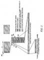
- FIG. 2illustrates a frame 200 that constitutes a portion of a radio frame.
- the radio framegenerally comprises a plurality of frames, which may form a concatenated continuum of frames.
- each frameincludes a composite control channel portion 210 comprising at least two control channel elements.
- FIG. 2illustrates the composite control channel including a plurality of control channel elements 212, 214, 216 and 218.
- the control channel elementseach comprise a codeword that provides a physical mapping of a logical control channel to a sequence of symbols, for example, QAM symbols.
- the control channel elementsare generally not the same type. In FIG. 2 , for example, control channel elements 212 and 218 have different sizes.
- Control channel elementsmay also be for uplink or downlink assignments, and have different associated information payload. Control channel elements may also be associated with different releases of the specification.
- the composite control channelincludes reference symbols, for example, pilot symbols, that are distinct from the control channel elements. The reference symbols are typically read by all remote units.
- Each framecorresponds to a transmission time interval (TTI).
- TTItransmission time interval
- An exemplary TTIis 1 ms.
- a single TTIhas a length 1 ms or 2 ms wherein the TTI is segmented into two sub-frames each having a 0.5 ms length.
- Such a constructionimplies the need to address multiple resource blocks, i.e., more than the number of resource blocks in a single 0.5 ms sub-frame, unless the resource block (RB) definition is expanded to automatically define the RB as extending over the entire length of the TTI, without regard for the TTI duration. This can lead to inefficiency, however, in the form of excessive per-RB capacity.
- a TTIis defined as the length of time over which a transmission or transport block is transmitted.
- a transmission block or transport blockis composed of a block of jointly coded data protected by a single CRC.
- an alternate definition of TTIcould be the length of transmission controlled by a single instance of control channel signaling.
- each control channel elementcontains only radio resource assignment information, for example, a codeword, exclusively addressed to a single wireless communication entity, for example, one of the remote units 110, 103 in FIG. 1 .
- the radio resource assignment informationincludes, among other remote unit specific information and a time-frequency radio resource assignment.
- the radio resource assignment informationmay additionally comprise modulation, code rate, information block size, antenna mode indicator, and other information.
- the wireless communication network infrastructure entitymay address more than one control channel element to the same wireless communication entity, for example, one of the remote units 110 or 103 in FIG.1 .
- the control channelmay include a first version of a codeword including a resource assignment on a first control channel element of the composite control channel and a second version of the codeword including a resource assignment on a second control channel element of the composite control channel, wherein both of the first and second versions of the codeword are addressed to the same mobile unit.
- the first and second versions of the codewordare the same, and in another embodiment the first and second versions of the codeword are different.
- the wireless communication network infrastructure entitytransmits the composite control channel including at least two control channel elements, wherein each elements includes corresponding first and second codeword versions addressed to the same entity.
- the wireless network infrastructure entitymay, typically based on the channel conditions of the entity, transmit the composite control channel including a single control channel element addressed to the entity.
- the remote unitIn examples where the composite control channel includes a composite control channel including at least two different types of radio resource assignment control channel elements, the remote unit generally determines the number of types of control channel elements constituting the composite control channel upon receiving the composite control channel.
- the composite control channelincludes type indicator information for each type of control channel element constituting the composite control channel. The remote unit may thus determine the number of types of control channel elements based on the type indicator information.
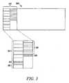
- a radio frame 300includes a composite control channel 310 comprising a first control channel element type 312 and a second control channel element type 316.
- the first control channel element typeis identified by a first indicator, for example, a sequence of bits, 314 appended to a last control channel element of the first type.
- the second control channel element typeis identified by a second indicator 318 appended to a last control channel element of the second type.
- the indicators 314 and 318are not present, and the control channel element type is determined after successful decoding of the control element.
- a type bitmay indicate an uplink or downlink control element in the decoded payload.
- the control elementmay be addressed to a single UE by a color coded CRC or by other means.
- the remote unitdetermines a number of control channel elements constituting at least one or at least two control channel elements of the composite control channel.
- FIG. 3is only one illustrative embodiment of the physical layout of the control channel elements on the radio-sub frame. In an alternate embodiment, the layout may be viewed as a logical layout, where the control channel elements comprise a number of sub-carriers distributed across the frame.
- the determining the number of types of control channel elements constituting the composite control channelincludes determining a number of uplink control channel elements and determining a number of downlink control channel elements.
- the number of uplink control channel elementsmay be determined based on a first sequence of bits and the number of downlink control channel elements based on a second sequence of bits embedded within the frame.
- the numbers of uplink and down link control channel elementsare determined based on where the first and second bit sequences are embedded within the frame.
- the use of different bit sequencesmay be used to indicate the different numbers of control channel elements. For example, a first bit sequence may indicate a first number of uplink elements and a second bit sequence may indicate a second number of uplink elements.
- the composite control channelincludes a first composite control channel portion in a first receive bandwidth on first center frequency and a second composite control channel in a second receive bandwidth on a second center frequency.
- a control channel structuremay be implemented to accommodate remote users having limited receive bandwidth.
- the composite control channelmay be divided into multiple composite control channel portions on corresponding center frequencies.
- terminalsmay have their receiver bandwidths limited to 10 MHz, while the carrier bandwidth is 20 MHz. In order accommodate such terminals of limited minimum bandwidth capability, it might be necessary to map the composite control channel to both the lower 10 Mhz and the upper 10 MHz sub-bands of the 20 MHz carrier. Terminals with 10 MHz capability camp on either one of the upper or lower sub-bands and receive the respective composite control channel.
- a wireless communication entityfor example, the remote unit, the terminals receives a composite control channel including at least two control channel elements.
- each the control channel elementonly contains radio resource assignment information exclusively addressed to a single wireless communication entity.
- the remote unitmay attempt to decode a single control channel element without first combining elements or it may attempt to decode a single control channel element after decoding or attempting to decode combined elements. Whether or not any combining is necessary depends generally on whether the remote unit is successful decoding single control channel elements. Combining may be required, for example, in instances where a cyclic redundancy check (CRC) or other information verification check fails after decoding a single control channel element, or where decoding is not successful.
- CRCcyclic redundancy check
- Information verificationtypically involves remote unit specific information, which may be included in the decoded control channel element, or masked with the encoded control channel element, or masked or fed into a CRC for CRC color coding.
- each of the plurality of control channel elementshas an associated root index, which may be used as a basis for combining the control channel elements. For example, if the composite control channel comprises 12 control channel elements, 4 of those elements may have the same associated root index and may be used as the basis for decoding and combining and decoding the control channel elements.
- the remote unitonly combines control channel elements from the same control channel portion. In other words, control channel elements from different control channel portions are not combined.
- the remote unitcombines at least two control channel elements of the composite control channel, wherein each control channel element is of the type that contains only radio resource assignment information exclusively addressed to a single wireless communication entity. Combining may be required, for example, in instances where a cyclic redundancy check (CRC) or other information verification check fails after decoding a single control channel element, or instances where decoding is not successful. Generally, however, the remote unit may attempt to decode a control channel element without first combining.
- CRCcyclic redundancy check
- the remote unitmay attempt to decode a control channel element without first combining.
- At least two of the control channel elementsare combined by summing soft information derived from first and second codeword information, wherein the first codeword information is within a first control channel element and the second codeword information is within a second control channel element.
- the combined control channel elementsare temporally aligned and superimposed (known as Chase combining).
- the superpositionmay involve max-ratio combining, or adding together log-likelihood-ratios (LLRs), or the like.
- LLRslog-likelihood-ratios
- the assumption hereis that the first and second codeword information is addressed to the same remote unit. If not, either the decoding or the information verification check after decoding will be unsuccessful. In the case of failure, the remote unit may form a different combination of control channel elements, for example, by combining a different set of control channel elements or by combining an additional element.
- At least two of the control channel elementsare combined by rearranging and summing soft information derived from different first and second codeword information, wherein the first codeword information is within a first control channel element and the second codeword information is within a second control channel element.
- the first codeword and second codewordmay comprise subsets of an information set and parity bits generated from a lower rate channel encoder. The subsets may be non-overlapping or partially overlapping. Soft information corresponding to overlapping codeword bit positions is typically summed in the remote unit, while non-overlapping bit positions are typically rearranged to an appropriate position for decoding.
- the remote unitecombines the at least two control channel elements according to predefined combinations of control channel elements.
- at least one of the pre-defined combinationsincludes a combination of at least two logically contiguous control channel elements.
- the logically contiguous control channel elementsmay or may not be physically contiguous. For example, if a set of sub-carriers distributed across frequency (a comb) is used for one control channel element, another control channel element may or may not physically occupy the sub-carriers adjacent to the first control channel element.
- logical adjacencyimplies physical adjacency and vice versa.
- at least two non-adjacent control channel elementsare combined, wherein the non-adjacent control elements may be physical or logical.
- the order in which the remote unit attempts to combine the control channel elements according to the pre-defined combinationsis based on one or more hypotheses or assumptions.
- the control channel elementsmay be combined based on a determination of the number of control channel elements constituting the composite control channel. Such a determination also includes determining the number of control channel elements constituting a particular type of control channel element in embodiments where the composite control channel includes more than one elements type as discussed above.
- the number of control channel elementsmay be determined, for example, based on the existence of control channel element number information included in the composite control channel.
- the number of control channel elementsmay be determined based on a sequence of bits appended to the composite control channel. In one implementation, different bit sequences are indicative of different numbers of control channel elements.
- the location of the sequence of bits within the frameis indicative of the number of the control channel elements.
- the same bit sequencemay be used to indicate different numbers of control channel elements depending on where the bit sequence is located within the frame.
- the number of control channel elementsmay also be determined based on data or messaging shared between a wireless communication device and a network infrastructure entity. This may occur in a message sent to all remote units via a broadcast channel sent occasionally or a broadcast message sent in each TTI. The number of control channel elements or subset of control channel elements that the remote unit should decode may also be sent via a message dedicated for that remote unit.
- control channelsmay be one or two control channel elements, with the size of the control element indicating the type of control element.
- Convolutional encodingmay be used for the control elements.
- the decodermay decode the first control element, check the CRC, and then stop decoding if the control element is designated for the user. If not, the decoding may commence from the point just prior to tail bit insertion on the first control element, through the end of the trellis comprised of both control elements. The CRC is again checked. In this way, control channel decoding may be achieved with less effort than if combined control elements were decoded from the beginning of the trellis. Note that the code rate for the single and two control elements must be the same in this embodiment.
- a portion of the composite control channelis allocated for assigning radio resources in each frame.
- the unallocated portion of the control channelmay be used for data transfer.
- a wireless communication network infrastructure entityfor example, a scheduler, may allocate a portion of the control channel for assigning radio resources in each frame by embedding a bit sequence within the corresponding frame.
- the location of the sequence of bits within the frameis indicative of the size of the control channel, for example, how many control channel elements are allocated for assigning radio resources to one or more remote units.
- the control channel elementsmay be addressed exclusively to a single remote unit or to more than one remote unit.
- the network infrastructure entitymay dynamically change the portion of the control channel for assigning radio resources in each frame by changing the bit sequence or the location bit sequence embedded in each frame before transmitting the frames. As suggested above, moreover, the network infrastructure entity may also dynamically allocate different types of control channel elements and the number thereof within a frame.
- the bit sequence embedded within the sub-frameis used to identify that the control channel element is for a remote unit.
- the bit sequence embedded within the sub-framemay be a data dependent bit sequence, such as a CRC processed with wireless communication device identification information, the codeword masked with wireless communication device identification information or the like.
- a first sub-framewhich may be the last sub-frame of a TTI, contains control information including modulation type, resources, or antenna mode indicator.
- Each control channelmay be one or more control channel elements, and the size of the control channel may be different in the first and second sub-frames.
- the second sub-framemay occur on the same or different portions of the control channel as the control information from the first sub-frame. If a different portion of the sub-frame is used, blind decoding complexity may be reduced by having the control channel elements in the second sub-frame known from the location of the remote units control channel elements from the first sub-frame.
- the wireless communication network infrastructure entityallocates a portion of the control channel for assigning radio resources in each frame by embedding a bit sequence within the corresponding frame. Allocating a portion of the control channel includes allocating all available portions of the control channel or less than all available portions thereof, wherein the unallocated portion may be used for other purposes, for example, data transfer.
- the wireless communication network infrastructure entitydynamically changes the portion of the control channel for assigning radio resources in each frame, wherein multiple frames constitutes a radio frame. According to this aspect of the disclosure, potentially, a different portion of each control channel in each frame, constituting the radio frame, may be allocated to assigning radio resources.
- the portion of the control channel for assigning radio resources in each framemay be changed dynamically by changing the location of the bit sequence embedded in each frame or by using different bit sequences, as discussed above.
- the wireless communication network infrastructure entitytransmits at least two frames, for example, constituting a radio frame, wherein each frame includes a control channel having a portion thereof allocated for radio resource assignment.
- a portion of the control channel used for radio resource assignmentis indicated based on where a bit sequence 220, referred to as a terminating marker or signature, is embedded within the corresponding frame.
- the portion of the control channele.g., the number of elements, used for radio resource assignment may be less than the entire control channel of the frame.
- different frames constituting a radio framemay allocate different portions of the corresponding control channels for radio resource assignment.
- a wireless communication devicecomprises a receiver capable of receiving a frame corresponding to a transmission time interval, wherein the frame includes a control channel and a bit sequence embedded within the frame.
- a controller communicably coupled to the receiveris configured for determining a portion of the control channel used for radio resource assignment based on where the corresponding bit sequence is embedded within the received frame, wherein the portion of the control channel used for radio resource assignment may be less than the entire control channel.
- the devicereceives a plurality of at least two frames, wherein each frame includes a control channel having at least two control channel elements and each frame includes a bit sequence embedded within the frame.
- the wireless communication devicedetermines a portion of the control channel used for radio resource assignment in each frame based on where the corresponding bit sequence is embedded within the frame.
- the portion of the control channel used for radio resource assignmentmay be less than the entire control channel and each frame may use different portions of the control channel for radio resource assignment based upon where the corresponding bit sequences is embedded within the frame.
- all control channel elements of the composite control channelcommunicate control channel information.
- the absence of control channel element number informatione.g., a bit sequence embedded within the frame, is indicative of the use of the full composite control channel for radio resource assignment.
- the remote unitmay assume a default number of control channel elements are used for assigning radio resources.
Landscapes
- Engineering & Computer Science (AREA)
- Computer Networks & Wireless Communication (AREA)
- Signal Processing (AREA)
- Physics & Mathematics (AREA)
- Probability & Statistics with Applications (AREA)
- Theoretical Computer Science (AREA)
- Mobile Radio Communication Systems (AREA)
Abstract
Description
- The present disclosure relates generally to wireless communications, and more particularly to controlling channel signaling for shared channels in wireless communication systems, for example cellular communication networks, corresponding entities and methods.
- Time division multiplexing (TDM) and frequency division multiplexing (FDM) methods, including hybrids thereof, have been proposed in addition to separate and joint coding of control channel signaling for scheduling downlink data transmission in the Long Term Evolution (LTE) of UMTS Terrestrial Radio Access (UTRA) and UTRA Network (UTRAN) specifications. In TDM and FDM transmissions of control channel signaling, the control information for downlink and uplink assignments may be transmitted over the first few symbols of the downlink frame or it may be spread out over the length of the frame. The frame duration is approximately 0.5 ms, though other durations are also possible.
PCT application publication no. WO 2005/050852 describes a method and system for providing channel assignment information used to support uplink (UL) and downlink (DL) channels. The system comprises at least one Node-B and at least one wireless transmit/receive unit (WTRU). The WTRU receives a message from a Node-B via a common control channel which is used for transmission of channel assignment information for both UL and DL transmissions. The message includes an indication of whether the message is intended for assigning radio resources to the UL channel or the DL channel. The WTRU determines whether the message is intended for the WTRU and, if so, the WTRU determines whether the message is for assigning radio resources to the UL channel or the DL channel and takes appropriate action.
US patent application publication no.US 2003/0112778 describes a method and apparatus for efficient multi-cast broadcasting for packet data systems. A single MAC_ID is used for broadcasting to a group of subscribers. By using the channel quality information of the group of subscribers, a base station determines the identity of the subscriber with the worst channel conditions. The timing and the transmission format of the multi-cast are then tailored so that the subscriber with the worst channel conditions is capable of recovering the transmission and so it is probable that the other subscribers will be able to recover the transmission as well. Hence, only a single MAC_ID need be used to make a single broadcast, rather than sending multiple transmissions to multiple subscribers.- A publication entitled "WCDMA for UMTS" by Harri Holma, Antti Toskala, 2000, Wiley and Sons, ISBN: 0 471 72051 8, pages 95-97, paragraph 6.4.5 describes a downlink dedicated channel which is transmitted on the Downlink Dedicated Physical Channel (Downlink DPCH). The Downlink DPCH applies time multiplexing for physical control information and user data transmission. The terms Dedicated Physical Data Channel (DPDCH) and Dedicated Physical Control Channel (DPCCH) are used for the downlink dedicated channels. The Downlink DPCH can use either open loop or closed loop transmit diversity to improve performance. In open loop transmit diversity, information is coded to be sent from two antennas.
- The various aspects, features and advantages of the disclosure will become more fully apparent to those having ordinary skill in the art upon careful consideration of the following Detailed Description and the accompanying drawings described below. The drawings may have been simplified for clarity and are not necessarily drawn to scale.
- The present invention provides a method in a wireless communication device according to the features defined in claim 1 and, further, a wireless communication device according to the features defined in claim 14.
- Further embodiments of the invention are according to the dependent claims.
FIG. 1 illustrates a wireless communication system.FIG. 2 illustrates a radio frame comprising a composite control channel having a plurality of control channel elements.FIG. 3 illustrates a composite control channel having different of control channel element types.FIG. 4 illustrates a process flow diagram.FIG. 5 illustrates another process flow diagram.FIG. 1 illustrates awireless communication system 100 comprising multiple cell serving base units forming a network distributed over a geographical region. A base unit may also be referred to as an access point, access terminal, Node-B, or similar terminologies known in the art. The one ormore base units remote units Base units downlink communication signals Remote units more base units uplink communication signals transmit antennas 109 at the base unit. When multiple antennas are used to serve each sector to provide various advanced communication modes, for example, adaptive beam-forming, transmit diversity, transmit SDMA, and multiple stream transmission, etc., multiple base units can be deployed. These base units within a sector may be highly integrated and may share various hardware and software components. For example, all base units co-located together to serve a cell can constitute what is traditionally known as a base station. The remote units may also comprise one or more transmitters and one or more receivers. The number of transmitters may be related, for example, to the number of transmit antennas at the remote unit.- In one embodiment, the communication system utilizes OFDMA or a next generation single-carrier based FDMA architecture for uplink transmissions, such as interleaved FDMA (IFDMA), Localized FDMA (LFDMA), DFT-spread OFDM (DFT-SOFDM) with IFDMA or LFDMA. In other embodiments, the architecture may also include the use of spreading techniques such as direct-sequence CDMA (DS-CDMA), multi-carrier CDMA (MC-CDMA), multi-carrier direct sequence CDMA (MC-DS-CDMA), Orthogonal Frequency and Code Division Multiplexing (OFCDM) with one or two dimensional spreading, or simpler time and frequency division multiplexing/multiple access techniques.
- Generally, a wireless communication network infrastructure scheduling entity located, for example, at each
base unit FIG. 1 , allocates or assigns radio resources to remote units in the network. The base units each include a scheduler for scheduling and allocating resources to remote units in corresponding serving areas or cells or sectors. In multiple access schemes such as those based on OFDM methods and the long term evolution of UTRA/UTRAN Study Item in 3GPP (also known as evolved UTRA/UTRAN (EUTRA/EUTRAN)), scheduling may be performed in the time and frequency dimensions using a Frequency Selective (FS) scheduler. In some embodiments, each remote unit may provide a frequency band channel quality indicator (CQI) or other metric to the scheduler to enable scheduling. - In OFDM systems or OFDM like systems such as DFT-SOFDM and IFDMA, a resource allocation is a frequency and time allocation that maps information for a particular base unit to sub-carrier resources from a set of available sub-carriers as determined by the scheduler. This allocation may depend, for example, on the frequency-selective channel-quality indication (CQI) or some other metric reported by the UE to the scheduler. The channel-coding rate and the modulation scheme, which may be different for different portions of the sub-carrier resources, are also determined by the scheduler and may also depend on the reported CQI or other metric. In code division multiplexed networks, the resource allocation is code allocation that maps information for a particular base unit to sub-carrier resources from a set of available sub-carriers as determined by the scheduler.
FIG. 2 illustrates aframe 200 that constitutes a portion of a radio frame. The radio frame generally comprises a plurality of frames, which may form a concatenated continuum of frames. InFIG. 2 , each frame includes a compositecontrol channel portion 210 comprising at least two control channel elements.FIG. 2 illustrates the composite control channel including a plurality ofcontrol channel elements FIG. 2 , for example, controlchannel elements - Each frame corresponds to a transmission time interval (TTI). An exemplary TTI is 1 ms. In one embodiment, a single TTI has a length 1 ms or 2 ms wherein the TTI is segmented into two sub-frames each having a 0.5 ms length. Such a construction however implies the need to address multiple resource blocks, i.e., more than the number of resource blocks in a single 0.5 ms sub-frame, unless the resource block (RB) definition is expanded to automatically define the RB as extending over the entire length of the TTI, without regard for the TTI duration. This can lead to inefficiency, however, in the form of excessive per-RB capacity. In case the RB is defined to extend over a fraction of the length of the TTI, it would be possible to independently address each of the resource blocks in the multiple sub-frames making up the TTI. Accordingly mechanisms are required to signal resource assignments in the case of a frame or TTI composed of concatenated sub-frames. Furthermore, mechanisms are required to be able to assign resources based on the needs of individual UE wherein fewer resources being assigned for a UE served with smaller packets while more resources are assigned to UE served with larger packets. In the case of UMTS (Universal Mobile Telecommunications System), a TTI is defined as the length of time over which a transmission or transport block is transmitted. A transmission block or transport block is composed of a block of jointly coded data protected by a single CRC. In the present instance, an alternate definition of TTI could be the length of transmission controlled by a single instance of control channel signaling.
- In one embodiment, each control channel element contains only radio resource assignment information, for example, a codeword, exclusively addressed to a single wireless communication entity, for example, one of the
remote units FIG. 1 . The radio resource assignment information includes, among other remote unit specific information and a time-frequency radio resource assignment. In other embodiments, the radio resource assignment information may additionally comprise modulation, code rate, information block size, antenna mode indicator, and other information. - In one embodiment, the wireless communication network infrastructure entity, for example, the scheduler, may address more than one control channel element to the same wireless communication entity, for example, one of the
remote units FIG.1 . More particularly, the control channel may include a first version of a codeword including a resource assignment on a first control channel element of the composite control channel and a second version of the codeword including a resource assignment on a second control channel element of the composite control channel, wherein both of the first and second versions of the codeword are addressed to the same mobile unit. In one embodiment, the first and second versions of the codeword are the same, and in another embodiment the first and second versions of the codeword are different. Whether codes words addressed to the same entity are different or the same affects how the addressed entity combines the control channel elements as discussed further below. Thus the wireless communication network infrastructure entity transmits the composite control channel including at least two control channel elements, wherein each elements includes corresponding first and second codeword versions addressed to the same entity. In some instances, the wireless network infrastructure entity may, typically based on the channel conditions of the entity, transmit the composite control channel including a single control channel element addressed to the entity. - In examples where the composite control channel includes a composite control channel including at least two different types of radio resource assignment control channel elements, the remote unit generally determines the number of types of control channel elements constituting the composite control channel upon receiving the composite control channel. In one example, the composite control channel includes type indicator information for each type of control channel element constituting the composite control channel. The remote unit may thus determine the number of types of control channel elements based on the type indicator information. In
FIG. 3 , aradio frame 300 includes acomposite control channel 310 comprising a first controlchannel element type 312 and a second controlchannel element type 316. The first control channel element type is identified by a first indicator, for example, a sequence of bits, 314 appended to a last control channel element of the first type. The second control channel element type is identified by asecond indicator 318 appended to a last control channel element of the second type. In another example, theindicators FIG. 3 is only one illustrative embodiment of the physical layout of the control channel elements on the radio-sub frame. In an alternate embodiment, the layout may be viewed as a logical layout, where the control channel elements comprise a number of sub-carriers distributed across the frame. - In one example, the determining the number of types of control channel elements constituting the composite control channel includes determining a number of uplink control channel elements and determining a number of downlink control channel elements. The number of uplink control channel elements may be determined based on a first sequence of bits and the number of downlink control channel elements based on a second sequence of bits embedded within the frame. In one example, the numbers of uplink and down link control channel elements are determined based on where the first and second bit sequences are embedded within the frame. Alternatively, the use of different bit sequences may be used to indicate the different numbers of control channel elements. For example, a first bit sequence may indicate a first number of uplink elements and a second bit sequence may indicate a second number of uplink elements.
- In some embodiments, the composite control channel includes a first composite control channel portion in a first receive bandwidth on first center frequency and a second composite control channel in a second receive bandwidth on a second center frequency. Such a control channel structure may be implemented to accommodate remote users having limited receive bandwidth. More generally, the composite control channel may be divided into multiple composite control channel portions on corresponding center frequencies. For example, terminals may have their receiver bandwidths limited to 10 MHz, while the carrier bandwidth is 20 MHz. In order accommodate such terminals of limited minimum bandwidth capability, it might be necessary to map the composite control channel to both the lower 10 Mhz and the upper 10 MHz sub-bands of the 20 MHz carrier. Terminals with 10 MHz capability camp on either one of the upper or lower sub-bands and receive the respective composite control channel.
- In the
process 400 ofFIG. 4 , at 410 a wireless communication entity, for example, the remote unit, the terminals receives a composite control channel including at least two control channel elements. In one embodiment, each the control channel element only contains radio resource assignment information exclusively addressed to a single wireless communication entity. - In
FIG. 4 , at 420, two or more control channel elements are combined before decoding at 430. Generally, however, the remote unit may attempt to decode a single control channel element without first combining elements or it may attempt to decode a single control channel element after decoding or attempting to decode combined elements. Whether or not any combining is necessary depends generally on whether the remote unit is successful decoding single control channel elements. Combining may be required, for example, in instances where a cyclic redundancy check (CRC) or other information verification check fails after decoding a single control channel element, or where decoding is not successful. Information verification typically involves remote unit specific information, which may be included in the decoded control channel element, or masked with the encoded control channel element, or masked or fed into a CRC for CRC color coding. - In some implementations, each of the plurality of control channel elements has an associated root index, which may be used as a basis for combining the control channel elements. For example, if the composite control channel comprises 12 control channel elements, 4 of those elements may have the same associated root index and may be used as the basis for decoding and combining and decoding the control channel elements. In embodiments where the control channel is divided into portions on corresponding center frequencies, as discussed above, the remote unit only combines control channel elements from the same control channel portion. In other words, control channel elements from different control channel portions are not combined.
- In some embodiments, the remote unit combines at least two control channel elements of the composite control channel, wherein each control channel element is of the type that contains only radio resource assignment information exclusively addressed to a single wireless communication entity. Combining may be required, for example, in instances where a cyclic redundancy check (CRC) or other information verification check fails after decoding a single control channel element, or instances where decoding is not successful. Generally, however, the remote unit may attempt to decode a control channel element without first combining.
- In one embodiment, at least two of the control channel elements are combined by summing soft information derived from first and second codeword information, wherein the first codeword information is within a first control channel element and the second codeword information is within a second control channel element. In such a combination, the combined control channel elements are temporally aligned and superimposed (known as Chase combining). The superposition may involve max-ratio combining, or adding together log-likelihood-ratios (LLRs), or the like. The assumption here is that the first and second codeword information is addressed to the same remote unit. If not, either the decoding or the information verification check after decoding will be unsuccessful. In the case of failure, the remote unit may form a different combination of control channel elements, for example, by combining a different set of control channel elements or by combining an additional element.
- In another embodiment, at least two of the control channel elements are combined by rearranging and summing soft information derived from different first and second codeword information, wherein the first codeword information is within a first control channel element and the second codeword information is within a second control channel element. For example, the first codeword and second codeword may comprise subsets of an information set and parity bits generated from a lower rate channel encoder. The subsets may be non-overlapping or partially overlapping. Soft information corresponding to overlapping codeword bit positions is typically summed in the remote unit, while non-overlapping bit positions are typically rearranged to an appropriate position for decoding.
- In one embodiment, the remote unite combines the at least two control channel elements according to predefined combinations of control channel elements. For example, at least one of the pre-defined combinations includes a combination of at least two logically contiguous control channel elements. The logically contiguous control channel elements may or may not be physically contiguous. For example, if a set of sub-carriers distributed across frequency (a comb) is used for one control channel element, another control channel element may or may not physically occupy the sub-carriers adjacent to the first control channel element. Or, if the logical and physical orderings of sub-carriers are identical, that is, there is a one-to-one mapping of logical and physical sub-carriers, then logical adjacency implies physical adjacency and vice versa. In other embodiments, at least two non-adjacent control channel elements are combined, wherein the non-adjacent control elements may be physical or logical.
- In some implementations, the order in which the remote unit attempts to combine the control channel elements according to the pre-defined combinations is based on one or more hypotheses or assumptions. For example, the control channel elements may be combined based on a determination of the number of control channel elements constituting the composite control channel. Such a determination also includes determining the number of control channel elements constituting a particular type of control channel element in embodiments where the composite control channel includes more than one elements type as discussed above. The number of control channel elements may be determined, for example, based on the existence of control channel element number information included in the composite control channel. For example, the number of control channel elements may be determined based on a sequence of bits appended to the composite control channel. In one implementation, different bit sequences are indicative of different numbers of control channel elements. In another implementation, the location of the sequence of bits within the frame is indicative of the number of the control channel elements. In this latter implementation, the same bit sequence may be used to indicate different numbers of control channel elements depending on where the bit sequence is located within the frame. The number of control channel elements may also be determined based on data or messaging shared between a wireless communication device and a network infrastructure entity. This may occur in a message sent to all remote units via a broadcast channel sent occasionally or a broadcast message sent in each TTI. The number of control channel elements or subset of control channel elements that the remote unit should decode may also be sent via a message dedicated for that remote unit.
- In one embodiment, control channels may be one or two control channel elements, with the size of the control element indicating the type of control element. Convolutional encoding may be used for the control elements. And the decoder may decode the first control element, check the CRC, and then stop decoding if the control element is designated for the user. If not, the decoding may commence from the point just prior to tail bit insertion on the first control element, through the end of the trellis comprised of both control elements. The CRC is again checked. In this way, control channel decoding may be achieved with less effort than if combined control elements were decoded from the beginning of the trellis. Note that the code rate for the single and two control elements must be the same in this embodiment.
- In some embodiments, a portion of the composite control channel is allocated for assigning radio resources in each frame. In these embodiments, the unallocated portion of the control channel may be used for data transfer. Thus a wireless communication network infrastructure entity, for example, a scheduler, may allocate a portion of the control channel for assigning radio resources in each frame by embedding a bit sequence within the corresponding frame. In one embodiment, the location of the sequence of bits within the frame is indicative of the size of the control channel, for example, how many control channel elements are allocated for assigning radio resources to one or more remote units. In this implementation, the control channel elements may be addressed exclusively to a single remote unit or to more than one remote unit. More generally, the network infrastructure entity may dynamically change the portion of the control channel for assigning radio resources in each frame by changing the bit sequence or the location bit sequence embedded in each frame before transmitting the frames. As suggested above, moreover, the network infrastructure entity may also dynamically allocate different types of control channel elements and the number thereof within a frame.
- In another embodiment, the bit sequence embedded within the sub-frame is used to identify that the control channel element is for a remote unit. In this case, the bit sequence embedded within the sub-frame may be a data dependent bit sequence, such as a CRC processed with wireless communication device identification information, the codeword masked with wireless communication device identification information or the like. In this embodiment, a first sub-frame, which may be the last sub-frame of a TTI, contains control information including modulation type, resources, or antenna mode indicator. Each control channel may be one or more control channel elements, and the size of the control channel may be different in the first and second sub-frames. The second sub-frame may occur on the same or different portions of the control channel as the control information from the first sub-frame. If a different portion of the sub-frame is used, blind decoding complexity may be reduced by having the control channel elements in the second sub-frame known from the location of the remote units control channel elements from the first sub-frame.
- In the process diagram 500 of
FIG. 5 , at 510, the wireless communication network infrastructure entity allocates a portion of the control channel for assigning radio resources in each frame by embedding a bit sequence within the corresponding frame. Allocating a portion of the control channel includes allocating all available portions of the control channel or less than all available portions thereof, wherein the unallocated portion may be used for other purposes, for example, data transfer. At 520, the wireless communication network infrastructure entity dynamically changes the portion of the control channel for assigning radio resources in each frame, wherein multiple frames constitutes a radio frame. According to this aspect of the disclosure, potentially, a different portion of each control channel in each frame, constituting the radio frame, may be allocated to assigning radio resources. The portion of the control channel for assigning radio resources in each frame may be changed dynamically by changing the location of the bit sequence embedded in each frame or by using different bit sequences, as discussed above. At 530, the wireless communication network infrastructure entity transmits at least two frames, for example, constituting a radio frame, wherein each frame includes a control channel having a portion thereof allocated for radio resource assignment. - In
FIG. 2 , for example, a portion of the control channel used for radio resource assignment is indicated based on where abit sequence 220, referred to as a terminating marker or signature, is embedded within the corresponding frame. Depending on where the bit sequence is located, the portion of the control channel, e.g., the number of elements, used for radio resource assignment may be less than the entire control channel of the frame. Generally, different frames constituting a radio frame may allocate different portions of the corresponding control channels for radio resource assignment. In one implementation, a wireless communication device, comprises a receiver capable of receiving a frame corresponding to a transmission time interval, wherein the frame includes a control channel and a bit sequence embedded within the frame. A controller communicably coupled to the receiver is configured for determining a portion of the control channel used for radio resource assignment based on where the corresponding bit sequence is embedded within the received frame, wherein the portion of the control channel used for radio resource assignment may be less than the entire control channel. - In the wireless communication device, for example, one of the
remote units FIG. 1 , the device receives a plurality of at least two frames, wherein each frame includes a control channel having at least two control channel elements and each frame includes a bit sequence embedded within the frame. In one embodiment, the wireless communication device determines a portion of the control channel used for radio resource assignment in each frame based on where the corresponding bit sequence is embedded within the frame. Generally, the portion of the control channel used for radio resource assignment may be less than the entire control channel and each frame may use different portions of the control channel for radio resource assignment based upon where the corresponding bit sequences is embedded within the frame. - In some instances, all control channel elements of the composite control channel communicate control channel information. In this particular embodiment, the absence of control channel element number information, e.g., a bit sequence embedded within the frame, is indicative of the use of the full composite control channel for radio resource assignment. For example, in the absence of control channel element number information, the remote unit may assume a default number of control channel elements are used for assigning radio resources.
- While the present disclosure and the best modes thereof have been described in a manner establishing possession and enabling those of ordinary skill to make and use the same, it will be understood and appreciated that there are equivalents to the exemplary embodiments disclosed herein and that modifications and variations may be made thereto without departing from the scope of the inventions, which are to be limited not by the exemplary embodiments but by the appended claims.
Claims (14)
- A method in a wireless communication device (103, 110), the method comprising :receiving (410), at the wireless communication device, a composite control channel (210, 310) including at least two control channel elements (212, 214, 216, 218, 312, 316),a first control channel element of the at least two control channel elements comprising a first set of sub-carriers and a second control channel element of the at least two control channel elements comprising a second set of sub-carriers,each control channel element contains only radio resource assignment information exclusively addressed to a single wireless communication device (103, 110);combining (420) at least two of the control channel elements (212, 214, 216, 218, 312, 316); anddecoding (430) the combined control channel elements to obtain radio resource assignment information.
- The method of Claim 1, wherein combining the at least two of the control channel elements (212, 214, 216, 218, 312, 316) includes summing information derived from identical first and second codeword information, the first codeword information being within the first control channel element and the second codeword information being within the second control channel element.
- The method of Claim 1, wherein combining the at least two of the control channel elements (212, 214, 216, 218, 312, 316) includes rearranging and summing soft information derived from different first and second codeword information, the first codeword information is within the first control channel element and the second codeword information is within the second control channel element.
- The method of Claim 1, wherein combining the at least two control channel elements (212, 214, 216, 218, 312, 316) according to predefined combinations of control channel elements.
- The method of Claim 1,combining the at least two control channel elements (212; 214, 216, 218, 312, 316) according to predefined combinations of control channel elements, whereinat least one of the pre-defined combinations includes a combination of at least two logically contiguous control channel elements.
- The method of Claim 1,
combining the at least two control channel elements (212, 214, 216, 218, 312, 316) according to predefined combinations of control channel elements,
wherein at least one of the pre-defined combinations includes a combination of at least two non-adjacent control channel elements. - The method of Claim 4,each of the plurality of control channel elements (212, 214, 216, 218, 312, 316) having an associated root index,combining the at least two control channel elements based on the associated root indices.
- The method of Claim 1, further comprisingdetermining a number of control channel elements (212, 214, 216, 218, 312, 316) constituting the composite control channel (210, 310), andcombining at least two of the control channel elements based on the determination of the number of control channel elements constituting the composite control channel.
- The method of Claim 8, wherein determining a number of control channel elements (212, 214, 216, 218, 312, 316) is based on existence of control channel element number information included in the composite control channel.
- The method of Claim 8, wherein determining a number of control channel elements (212, 214, 216, 218, 312, 316) is based on data shared between a wireless communication device (103, 110) and a network infrastructure entity.
- The method of Claim 9, further comprising determining that all control channel elements (212, 214, 216, 218, 312, 316) of the composite control channel (210, 310) communicate control channel information in the absence of control channel element number information.
- The method of Claim 8, wherein determining a number of control channel elements (212, 214, 216, 218, 312, 316) based on a sequence of bits appended to the composite control channel.
- The method of Claim 1, whereinreceiving the composite control channel (210, 310) includes receiving a first composite control channel in a first receive bandwidth on first center frequency and receiving a second composite control channel in a second receive bandwidth on a second center frequency,at least the first composite control channel including at least two control channel elements (212, 214, 216, 218, 312, 316).
- A wireless communication device (103, 110) comprising:a transceiver,the wireless communication device (103, 110) further comprising:the transceiver configured to a receive a composite control channel (210, 310) including at least two control channel elements (212, 214, 216, 218, 312, 316), wherein a first control channel element of the at least two control channel elements comprises a first set of sub-carriers and a second control channel element of the at least two control channel elements comprises a second set of sub-carriers, and wherein each control channel element contains only radio resource assignment information exclusively addressed to a single wireless communication device (103, 110);the wireless communication device configured to combine at least two of the control channel elements and to decode the combined control channel elements to obtain radio resource assignment information.
Priority Applications (9)
| Application Number | Priority Date | Filing Date | Title |
|---|---|---|---|
| EP11157379AEP2328380A1 (en) | 2006-10-04 | 2007-08-22 | Radio resource assignment in control channel in wireless communication systems |
| PL07814333TPL2070362T3 (en) | 2006-10-04 | 2007-08-22 | Radio resource allocation in the control channel in wireless communication systems |
| PL09007846TPL2099245T3 (en) | 2006-10-04 | 2007-08-22 | Allocation of a radio resource in a control channel in wireless communication systems |
| PL09007847TPL2094048T3 (en) | 2006-10-04 | 2007-08-22 | Radio resource assignment in control channel in wireless communication systems |
| EP11157380AEP2328372A3 (en) | 2006-10-04 | 2007-08-22 | Radio resource assignment in control channel in wireless communication systems |
| EP09007846AEP2099245B1 (en) | 2006-10-04 | 2007-08-22 | Radio resource assignment in control channel in wireless communication systems |
| EP09007847AEP2094048B1 (en) | 2006-10-04 | 2007-08-22 | Radio resource assignment in control channel in wireless communication systems |
| EP11157378.8AEP2328373B1 (en) | 2006-10-04 | 2007-08-22 | Radio resource assignment in control channel in wireless communication systems |
| EP11170222AEP2367376A1 (en) | 2006-10-04 | 2007-08-22 | Radio resource assignment in control channel in wireless communication systems |
Applications Claiming Priority (2)
| Application Number | Priority Date | Filing Date | Title |
|---|---|---|---|
| US11/538,758US20080084853A1 (en) | 2006-10-04 | 2006-10-04 | Radio resource assignment in control channel in wireless communication systems |
| PCT/US2007/076477WO2008042514A1 (en) | 2006-10-04 | 2007-08-22 | Radio resource assignment in control channel in wireless communication systems |
Related Child Applications (8)
| Application Number | Title | Priority Date | Filing Date |
|---|---|---|---|
| EP11157379ADivision-IntoEP2328380A1 (en) | 2006-10-04 | 2007-08-22 | Radio resource assignment in control channel in wireless communication systems |
| EP09007846ADivisionEP2099245B1 (en) | 2006-10-04 | 2007-08-22 | Radio resource assignment in control channel in wireless communication systems |
| EP09007846ADivision-IntoEP2099245B1 (en) | 2006-10-04 | 2007-08-22 | Radio resource assignment in control channel in wireless communication systems |
| EP11157380ADivision-IntoEP2328372A3 (en) | 2006-10-04 | 2007-08-22 | Radio resource assignment in control channel in wireless communication systems |
| EP09007847ADivisionEP2094048B1 (en) | 2006-10-04 | 2007-08-22 | Radio resource assignment in control channel in wireless communication systems |
| EP09007847ADivision-IntoEP2094048B1 (en) | 2006-10-04 | 2007-08-22 | Radio resource assignment in control channel in wireless communication systems |
| EP11157378.8ADivisionEP2328373B1 (en) | 2006-10-04 | 2007-08-22 | Radio resource assignment in control channel in wireless communication systems |
| EP11157378.8ADivision-IntoEP2328373B1 (en) | 2006-10-04 | 2007-08-22 | Radio resource assignment in control channel in wireless communication systems |
Publications (2)
| Publication Number | Publication Date |
|---|---|
| EP2070362A1 EP2070362A1 (en) | 2009-06-17 |
| EP2070362B1true EP2070362B1 (en) | 2011-04-27 |
Family
ID=38819854
Family Applications (7)
| Application Number | Title | Priority Date | Filing Date |
|---|---|---|---|
| EP07814333AActiveEP2070362B1 (en) | 2006-10-04 | 2007-08-22 | Radio resource assignment in control channel in wireless communication systems |
| EP11157379AWithdrawnEP2328380A1 (en) | 2006-10-04 | 2007-08-22 | Radio resource assignment in control channel in wireless communication systems |
| EP11157380ACeasedEP2328372A3 (en) | 2006-10-04 | 2007-08-22 | Radio resource assignment in control channel in wireless communication systems |
| EP09007847AActiveEP2094048B1 (en) | 2006-10-04 | 2007-08-22 | Radio resource assignment in control channel in wireless communication systems |
| EP09007846AActiveEP2099245B1 (en) | 2006-10-04 | 2007-08-22 | Radio resource assignment in control channel in wireless communication systems |
| EP11157378.8AActiveEP2328373B1 (en) | 2006-10-04 | 2007-08-22 | Radio resource assignment in control channel in wireless communication systems |
| EP11170222ACeasedEP2367376A1 (en) | 2006-10-04 | 2007-08-22 | Radio resource assignment in control channel in wireless communication systems |
Family Applications After (6)
| Application Number | Title | Priority Date | Filing Date |
|---|---|---|---|
| EP11157379AWithdrawnEP2328380A1 (en) | 2006-10-04 | 2007-08-22 | Radio resource assignment in control channel in wireless communication systems |
| EP11157380ACeasedEP2328372A3 (en) | 2006-10-04 | 2007-08-22 | Radio resource assignment in control channel in wireless communication systems |
| EP09007847AActiveEP2094048B1 (en) | 2006-10-04 | 2007-08-22 | Radio resource assignment in control channel in wireless communication systems |
| EP09007846AActiveEP2099245B1 (en) | 2006-10-04 | 2007-08-22 | Radio resource assignment in control channel in wireless communication systems |
| EP11157378.8AActiveEP2328373B1 (en) | 2006-10-04 | 2007-08-22 | Radio resource assignment in control channel in wireless communication systems |
| EP11170222ACeasedEP2367376A1 (en) | 2006-10-04 | 2007-08-22 | Radio resource assignment in control channel in wireless communication systems |
Country Status (11)
| Country | Link |
|---|---|
| US (4) | US20080084853A1 (en) |
| EP (7) | EP2070362B1 (en) |
| JP (4) | JP4984307B2 (en) |
| KR (7) | KR101420579B1 (en) |
| CN (6) | CN102573077B (en) |
| AT (3) | ATE546968T1 (en) |
| BR (1) | BRPI0717508B1 (en) |
| DE (2) | DE602007014235D1 (en) |
| ES (4) | ES2381633T3 (en) |
| PL (3) | PL2070362T3 (en) |
| WO (1) | WO2008042514A1 (en) |
Families Citing this family (32)
| Publication number | Priority date | Publication date | Assignee | Title |
|---|---|---|---|---|
| US8611300B2 (en)* | 2006-01-18 | 2013-12-17 | Motorola Mobility Llc | Method and apparatus for conveying control channel information in OFDMA system |
| US7778307B2 (en)* | 2006-10-04 | 2010-08-17 | Motorola, Inc. | Allocation of control channel for radio resource assignment in wireless communication systems |
| US20080084853A1 (en)* | 2006-10-04 | 2008-04-10 | Motorola, Inc. | Radio resource assignment in control channel in wireless communication systems |
| US8295248B2 (en)* | 2006-11-03 | 2012-10-23 | Motorola Mobility Llc | Scheduling remote units in wireless communication systems |
| CN101662820B (en)* | 2007-01-09 | 2014-12-24 | 华为技术有限公司 | Base station device, mobile station device, control information transmitting method, control information receiving method and program |
| RU2009137909A (en)* | 2007-03-14 | 2011-04-20 | Интердиджитал Текнолоджи Корпорейшн (Us) | ACK / NACK TRANSMISSION AND TRANSMISSION POWER COMMUNICATION FEEDBACK IN IMPROVED UTRA |
| RU2476992C2 (en)* | 2007-06-19 | 2013-02-27 | Панасоник Корпорэйшн | Wireless communication apparatus and response signal spreading method |
| US8379601B2 (en)* | 2007-08-16 | 2013-02-19 | Motorola Mobility Llc | Method and system for selective use of control channel element based implicit pointing |
| ES2647230T3 (en) | 2007-10-29 | 2017-12-20 | Panasonic Corporation | Control Channel Assignment |
| AR069102A1 (en)* | 2007-10-29 | 2009-12-30 | Interdigital Patent Holdings | METHOD AND APPLIANCE FOR THE MANAGEMENT OF ANSWER ACCESS CHANNEL ANSWERS |
| EP3182605B1 (en) | 2007-10-29 | 2019-12-04 | Optis Wireless Technology, LLC | Search space based on control channel elements aggregation size |
| WO2009157167A1 (en)* | 2008-06-23 | 2009-12-30 | パナソニック株式会社 | Wireless communication base station apparatus and reference signal allocation method |
| CN102123506A (en)* | 2008-07-14 | 2011-07-13 | 华为技术有限公司 | Resource allocation method and device for multiple users |
| CN101309460B (en) | 2008-07-14 | 2011-04-20 | 华为技术有限公司 | Method and device for multi-user resource allocation |
| WO2010013960A2 (en) | 2008-07-31 | 2010-02-04 | Samsung Electronics Co., Ltd. | Method and apparatus for allocating resource of multiple carriers in ofdma system |
| KR101537614B1 (en) | 2008-08-11 | 2015-07-22 | 엘지전자 주식회사 | Method for signaling control information in a wireless communication system using a plurality of frequency blocks |
| BRPI0920413B1 (en)* | 2008-10-29 | 2020-09-24 | Sharp Kabushiki Kaisha | MOBILE STATION DEVICE AND BASE STATION DEVICE |
| WO2010058887A1 (en) | 2008-11-18 | 2010-05-27 | Lg Electronics Inc. | A method and device for allocating a broadcast channel in a wireless mobile communication system |
| US9450727B2 (en)* | 2009-02-03 | 2016-09-20 | Google Technology Holdings LLC | Physical layer acknowledgement signaling resource allocation in wireless communication systems |
| US9742516B2 (en)* | 2011-07-28 | 2017-08-22 | Blackberry Limited | Method and system for control format detection in heterogeneous cellular networks |
| JP5935148B2 (en) | 2011-11-02 | 2016-06-15 | シャープ株式会社 | Mobile station apparatus, base station apparatus, communication method, and integrated circuit |
| EP2893759B1 (en)* | 2012-09-07 | 2020-12-30 | Samsung Electronics Co., Ltd. | Method and apparatus for signalling resource allocation information in an asymmetric multicarrier communication network |
| US9301291B2 (en)* | 2012-09-28 | 2016-03-29 | Telefonaktiebolaget L M Ericsson (Publ) | Methods of processing enhanced physical downlink control channel information including differentiating between sets of physical resource block pairs, and related network nodes and user equipments |
| EP2901590B1 (en)* | 2012-09-28 | 2019-05-22 | Intel Corporation | Blind decoding for an enhanced physical downlink control channel (epdcch) |
| JP6501776B2 (en) | 2013-08-07 | 2019-04-17 | サムスン エレクトロニクス カンパニー リミテッド | Method and apparatus for transmitting and receiving resource allocation information in a wireless communication system |
| EP3148109A4 (en)* | 2014-06-13 | 2017-07-05 | Huawei Technologies Co., Ltd. | Downlink multi-access method, base station and terminal |
| GB2538286A (en)* | 2015-05-14 | 2016-11-16 | Fujitsu Ltd | Control channels in wireless communication |
| WO2018027705A1 (en)* | 2016-08-10 | 2018-02-15 | 华为技术有限公司 | Signal transmission method, apparatus, and system |
| US20190373589A1 (en)* | 2016-12-15 | 2019-12-05 | Lg Electronics Inc. | Method and terminal for decoding downlink control information according to multi-aggregation level |
| EP3671511B1 (en)* | 2018-12-19 | 2022-07-06 | Rohde & Schwarz GmbH & Co. KG | Communication system and method |
| CN109769301A (en)* | 2019-02-13 | 2019-05-17 | 北京中兴高达通信技术有限公司 | The processing method and processing device of channel, electronic device |
| WO2022112822A1 (en)* | 2020-11-25 | 2022-06-02 | Telefonaktiebolaget Lm Ericsson (Publ) | Method for multisite transmission using complementary codes |
Family Cites Families (85)
| Publication number | Priority date | Publication date | Assignee | Title |
|---|---|---|---|---|
| US4491947A (en) | 1983-05-31 | 1985-01-01 | At&T Bell Laboratories | Technique for dynamic scheduling of integrated circuit- and packet-switching in a multi-beam SS/TDMA system |
| US4675863A (en) | 1985-03-20 | 1987-06-23 | International Mobile Machines Corp. | Subscriber RF telephone system for providing multiple speech and/or data signals simultaneously over either a single or a plurality of RF channels |
| US4939746A (en)* | 1987-06-03 | 1990-07-03 | General Electric Company | Trunked radio repeater system |
| JPH0666832B2 (en)* | 1988-12-12 | 1994-08-24 | 富士通株式会社 | Sub-address dial-in control method |
| US5151919A (en) | 1990-12-17 | 1992-09-29 | Ericsson-Ge Mobile Communications Holding Inc. | Cdma subtractive demodulation |
| US6018528A (en) | 1994-04-28 | 2000-01-25 | At&T Corp | System and method for optimizing spectral efficiency using time-frequency-code slicing |
| US6070071A (en) | 1995-11-13 | 2000-05-30 | Interwave Communications International Ltd. | Multiple antenna cellular network |
| US6058307A (en) | 1995-11-30 | 2000-05-02 | Amsc Subsidiary Corporation | Priority and preemption service system for satellite related communication using central controller |
| US6031826A (en) | 1996-08-27 | 2000-02-29 | Ericsson Inc. | Fast associated control channel technique for satellite communications |
| JP3437411B2 (en) | 1997-05-20 | 2003-08-18 | 松下電器産業株式会社 | Receiving device, transmitting device, base station device and mobile station device using them |
| US6567416B1 (en) | 1997-10-14 | 2003-05-20 | Lucent Technologies Inc. | Method for access control in a multiple access system for communications networks |
| US6574211B2 (en) | 1997-11-03 | 2003-06-03 | Qualcomm Incorporated | Method and apparatus for high rate packet data transmission |
| US6097772A (en) | 1997-11-24 | 2000-08-01 | Ericsson Inc. | System and method for detecting speech transmissions in the presence of control signaling |
| JPH11355195A (en) | 1998-06-05 | 1999-12-24 | Nec Corp | Satellite communication equipment |
| US6252910B1 (en)* | 1998-11-11 | 2001-06-26 | Comspace Corporation | Bandwidth efficient QAM on a TDM-FDM system for wireless communications |
| US6317435B1 (en) | 1999-03-08 | 2001-11-13 | Qualcomm Incorporated | Method and apparatus for maximizing the use of available capacity in a communication system |
| US6633762B1 (en) | 1999-08-06 | 2003-10-14 | Lucent Technologies Inc. | Smart mobile assisted handoff (MAHO) method that disables MAHO |
| CA2397893C (en)* | 2000-01-20 | 2011-05-03 | Nortel Networks Limited | Hybrid arq schemes with soft combining in variable rate packet data applications |
| US6697422B1 (en) | 2000-03-17 | 2004-02-24 | Lucent Technologies Inc. | Variable encoding levels for encoding in-band control messages in wireless telecommunication systems |
| US20060072520A1 (en) | 2000-03-23 | 2006-04-06 | Chitrapu Prabhakar R | Time synchronized standby state to the GPRS medium access control protocol with applications to mobile satellite systems |
| US6934275B1 (en)* | 2000-04-17 | 2005-08-23 | Motorola, Inc. | Apparatus and method for providing separate forward dedicated and shared control channels in a communications system |
| US7248841B2 (en) | 2000-06-13 | 2007-07-24 | Agee Brian G | Method and apparatus for optimization of wireless multipoint electromagnetic communication networks |
| EP1176749A3 (en)* | 2000-06-20 | 2005-07-13 | Matsushita Electric Industrial Co., Ltd. | Radio communication system |
| US20020029229A1 (en)* | 2000-06-30 | 2002-03-07 | Jakopac David E. | Systems and methods for data compression |
| US6856812B1 (en)* | 2000-06-30 | 2005-02-15 | Lucent Technologies Inc. | Downlink power control method for wireless packet data network |
| US20020032030A1 (en) | 2000-08-28 | 2002-03-14 | Berglund Arne Kristian | Communication system |
| CA2853156C (en) | 2000-11-15 | 2015-03-24 | Wi-Lan, Inc. | Improved frame structure for a communication system using adaptive modulation |
| US6947748B2 (en) | 2000-12-15 | 2005-09-20 | Adaptix, Inc. | OFDMA with adaptive subcarrier-cluster configuration and selective loading |
| US6885630B2 (en) | 2001-01-03 | 2005-04-26 | At&T Corp. | Combined simulcasting and dedicated services in a wireless communication system |
| KR100724921B1 (en)* | 2001-02-16 | 2007-06-04 | 삼성전자주식회사 | Code generation and decoding device and method in communication system |
| US7041449B2 (en) | 2001-03-19 | 2006-05-09 | Wisconsin Alumni Research Foundation | Methods of screening for compounds that inhibit expression of biomarker sequences differentially expressed with age in mice |
| US6807426B2 (en)* | 2001-04-12 | 2004-10-19 | Qualcomm Incorporated | Method and apparatus for scheduling transmissions in a communication system |
| US6751187B2 (en) | 2001-05-17 | 2004-06-15 | Qualcomm Incorporated | Method and apparatus for processing data for transmission in a multi-channel communication system using selective channel transmission |
| US6975867B2 (en) | 2001-08-31 | 2005-12-13 | Sanyo Electric Co., Ltd. | Radio base apparatus, communication channel allocation method, and allocation program |
| US6856604B2 (en)* | 2001-12-19 | 2005-02-15 | Qualcomm Incorporated | Efficient multi-cast broadcasting for packet data systems |
| US7292854B2 (en) | 2002-02-15 | 2007-11-06 | Lucent Technologies Inc. | Express signaling in a wireless communication system |
| US7508804B2 (en) | 2002-04-05 | 2009-03-24 | Alcatel-Lucent Usa Inc. | Shared signaling for multiple user equipment |
| EP1506656B1 (en)* | 2002-05-08 | 2012-01-11 | Nokia Corporation | Dynamic allocation of a radio resource |
| JP3597516B2 (en) | 2002-05-30 | 2004-12-08 | 松下電器産業株式会社 | Scheduling device and communication method |
| US8107885B2 (en) | 2002-10-30 | 2012-01-31 | Motorola Mobility, Inc. | Method and apparatus for providing a distributed architecture digital wireless communication system |
| US8179833B2 (en) | 2002-12-06 | 2012-05-15 | Qualcomm Incorporated | Hybrid TDM/OFDM/CDM reverse link transmission |
| US7016319B2 (en)* | 2003-03-24 | 2006-03-21 | Motorola, Inc. | Method and apparatus for reducing co-channel interference in a communication system |
| US7640373B2 (en) | 2003-04-25 | 2009-12-29 | Motorola, Inc. | Method and apparatus for channel quality feedback within a communication system |
| US7321780B2 (en) | 2003-04-30 | 2008-01-22 | Motorola, Inc. | Enhanced uplink rate selection by a communication device during soft handoff |
| US7012912B2 (en) | 2003-05-14 | 2006-03-14 | Qualcomm Incorporated | Power control and scheduling in an OFDM system |
| FI20031200A0 (en) | 2003-08-26 | 2003-08-26 | Nokia Corp | Procedure and base station for controlling link matching and packet time setting in an HSDPA radio system |
| US7200405B2 (en)* | 2003-11-18 | 2007-04-03 | Interdigital Technology Corporation | Method and system for providing channel assignment information used to support uplink and downlink channels |
| CN1311673C (en)* | 2003-12-03 | 2007-04-18 | 华为技术有限公司 | Method for transmitting multi-protocol tag exchange protocol data unit |
| ATE437494T1 (en) | 2004-01-23 | 2009-08-15 | Koninkl Philips Electronics Nv | PACKET DATA MULTICAST COMMUNICATION SYSTEM, STATION AND OPERATING PROCEDURES FOR THE SYSTEM |
| KR100594111B1 (en) | 2004-03-12 | 2006-06-30 | 삼성전자주식회사 | Data transmission method and system in broadband wireless access system using multiple coding for each frequency band |
| US8014264B2 (en) | 2004-05-01 | 2011-09-06 | Neocific, Inc. | Methods and apparatus for communication with time-division duplexing |
| WO2005115022A2 (en) | 2004-05-13 | 2005-12-01 | Widefi, Inc. | Non-frequency translating repeater with detection and media access control |
| US7486956B2 (en) | 2004-05-19 | 2009-02-03 | Qualcomm, Incorporated | Channel estimation and channel quality indicator (CQI) measurements for a high-speed downlink GPRS |
| KR100703517B1 (en) | 2004-06-19 | 2007-04-03 | 삼성전자주식회사 | System and method for allocating stable channel in broadband wireless access communication system |
| MX2007001704A (en)* | 2004-08-12 | 2007-04-12 | Interdigital Tech Corp | Method and system for controlling access to a wireless communication medium. |
| ATE363189T1 (en) | 2004-09-13 | 2007-06-15 | Alcatel Lucent | ESTIMATION OF TRANSMISSION QUALITY IN A RADIO NETWORK |
| CN100438685C (en)* | 2004-09-20 | 2008-11-26 | 上海贝尔阿尔卡特股份有限公司 | Method and equipment for treating multiuser/multibusiness |
| WO2006034401A2 (en)* | 2004-09-23 | 2006-03-30 | The Regents Of The University Of California | Multiple sub-carrier selection diversity architecture and method for wireless ofdm |
| WO2006039812A1 (en) | 2004-10-15 | 2006-04-20 | Nortel Networks Limited | Communication resource allocation systems and methods |
| US20060094432A1 (en)* | 2004-11-03 | 2006-05-04 | Jen-Chun Chang | Handoff method for mobile communication system |
| US20060104204A1 (en)* | 2004-11-12 | 2006-05-18 | Johan Hansson | Power efficient mobile terminal reception mode |
| ITVA20040054A1 (en)* | 2004-11-23 | 2005-02-23 | St Microelectronics Srl | METHOD FOR ESTIMATING CANE ATTENUATION COEFFICIENTS, METHOD OF RECEIVING SYMBOLS AND RELATIVE RECEIVER AND TRANSMITTER TO SINGLE ANTENNA OR MULTI-ANTENNA |
| US7158795B2 (en)* | 2004-12-08 | 2007-01-02 | Spreadtrum Communications Corporation | Dummy PCH block detection for power saving in GSM handset |
| KR100810290B1 (en) | 2004-12-14 | 2008-03-07 | 삼성전자주식회사 | Method and system for allocation data burst in a wireless communication system |
| US20060146756A1 (en)* | 2004-12-30 | 2006-07-06 | Fan Wang | Downlink resource allocation for time offset downlink packets |
| WO2006102746A1 (en) | 2005-03-30 | 2006-10-05 | Nortel Networks Limited | Methods and systems for transmission of orthogonal frequency division multiplexed symbols |
| US20070058595A1 (en) | 2005-03-30 | 2007-03-15 | Motorola, Inc. | Method and apparatus for reducing round trip latency and overhead within a communication system |
| US8031583B2 (en) | 2005-03-30 | 2011-10-04 | Motorola Mobility, Inc. | Method and apparatus for reducing round trip latency and overhead within a communication system |
| US20060245384A1 (en) | 2005-05-02 | 2006-11-02 | Talukdar Anup K | Method and apparatus for transmitting data |
| CN101213801B (en)* | 2005-05-27 | 2012-12-12 | 诺基亚公司 | Expanded signalling capability for network element, user equipment and system |
| US7177804B2 (en) | 2005-05-31 | 2007-02-13 | Microsoft Corporation | Sub-band voice codec with multi-stage codebooks and redundant coding |
| US20070025345A1 (en)* | 2005-07-27 | 2007-02-01 | Bachl Rainer W | Method of increasing the capacity of enhanced data channel on uplink in a wireless communications systems |
| US20070025468A1 (en) | 2005-07-28 | 2007-02-01 | Weidong Li | GMSK/8-PSK mix-mode support for GSM/GPRS/EDGE compliant handsets |
| US8077690B2 (en)* | 2005-08-24 | 2011-12-13 | Motorola Mobility, Inc. | Resource allocation in cellular communication systems |
| GB2429605B (en)* | 2005-08-24 | 2008-06-04 | Ipwireless Inc | Apparatus and method for communicating signalling information |
| KR20070027844A (en)* | 2005-08-29 | 2007-03-12 | 삼성전자주식회사 | Method and apparatus for transmitting channel quality information in wireless communication system |
| US7664091B2 (en)* | 2005-10-03 | 2010-02-16 | Motorola, Inc. | Method and apparatus for control channel transmission and reception |
| WO2007060589A2 (en)* | 2005-11-28 | 2007-05-31 | Koninklijke Philips Electronics N.V. | Method and apparatus for error-correction in a communication system |
| US8611300B2 (en)* | 2006-01-18 | 2013-12-17 | Motorola Mobility Llc | Method and apparatus for conveying control channel information in OFDMA system |
| US7464313B2 (en) | 2006-03-09 | 2008-12-09 | Motorola, Inc. | Hybrid approach for data transmission using a combination of single-user and multi-user packets |
| US20070211657A1 (en) | 2006-03-09 | 2007-09-13 | Motorola, Inc. | Apparatus and Method for Assigning Time Domain Resources to a Receiver |
| CN101305522A (en) | 2006-04-28 | 2008-11-12 | 三菱电机研究实验室 | Method and system for processing reference signal using transmission time interval packet |
| US8400998B2 (en)* | 2006-08-23 | 2013-03-19 | Motorola Mobility Llc | Downlink control channel signaling in wireless communication systems |
| US7778307B2 (en)* | 2006-10-04 | 2010-08-17 | Motorola, Inc. | Allocation of control channel for radio resource assignment in wireless communication systems |
| US20080084853A1 (en) | 2006-10-04 | 2008-04-10 | Motorola, Inc. | Radio resource assignment in control channel in wireless communication systems |
- 2006
- 2006-10-04USUS11/538,758patent/US20080084853A1/ennot_activeAbandoned
- 2007
- 2007-08-22DEDE602007014235Tpatent/DE602007014235D1/enactiveActive
- 2007-08-22EPEP07814333Apatent/EP2070362B1/enactiveActive
- 2007-08-22CNCN201110443781.8Apatent/CN102573077B/ennot_activeExpired - Fee Related
- 2007-08-22CNCN201110443595.4Apatent/CN102547849B/enactiveActive
- 2007-08-22CNCN201110443579.5Apatent/CN102572943B/ennot_activeExpired - Fee Related
- 2007-08-22KRKR1020137003944Apatent/KR101420579B1/enactiveActive
- 2007-08-22PLPL07814333Tpatent/PL2070362T3/enunknown
- 2007-08-22CNCN201110443567.2Apatent/CN102438317B/ennot_activeExpired - Fee Related
- 2007-08-22CNCN201110443544.1Apatent/CN102572942B/enactiveActive
- 2007-08-22WOPCT/US2007/076477patent/WO2008042514A1/enactiveApplication Filing
- 2007-08-22EPEP11157379Apatent/EP2328380A1/ennot_activeWithdrawn
- 2007-08-22ESES09007846Tpatent/ES2381633T3/enactiveActive
- 2007-08-22PLPL09007847Tpatent/PL2094048T3/enunknown
- 2007-08-22CNCN2007800373147Apatent/CN101523947B/ennot_activeExpired - Fee Related
- 2007-08-22EPEP11157380Apatent/EP2328372A3/ennot_activeCeased
- 2007-08-22PLPL09007846Tpatent/PL2099245T3/enunknown
- 2007-08-22EPEP09007847Apatent/EP2094048B1/enactiveActive
- 2007-08-22ESES07814333Tpatent/ES2363718T3/enactiveActive
- 2007-08-22ATAT09007846Tpatent/ATE546968T1/enactive
- 2007-08-22ATAT09007847Tpatent/ATE501620T1/ennot_activeIP Right Cessation
- 2007-08-22EPEP09007846Apatent/EP2099245B1/enactiveActive
- 2007-08-22EPEP11157378.8Apatent/EP2328373B1/enactiveActive
- 2007-08-22DEDE602007013094Tpatent/DE602007013094D1/enactiveActive
- 2007-08-22ATAT07814333Tpatent/ATE507696T1/ennot_activeIP Right Cessation
- 2007-08-22ESES11157378Tpatent/ES2864744T3/enactiveActive
- 2007-08-22KRKR1020117009136Apatent/KR20110059781A/ennot_activeCeased
- 2007-08-22KRKR1020137003939Apatent/KR101344155B1/enactiveActive
- 2007-08-22KRKR1020127013639Apatent/KR101344104B1/enactiveActive
- 2007-08-22ESES09007847Tpatent/ES2361704T3/enactiveActive
- 2007-08-22BRBRPI0717508-6Apatent/BRPI0717508B1/enactiveIP Right Grant
- 2007-08-22KRKR1020097006930Apatent/KR101116942B1/ennot_activeExpired - Fee Related
- 2007-08-22KRKR1020127013638Apatent/KR101283730B1/enactiveActive
- 2007-08-22JPJP2009530499Apatent/JP4984307B2/enactiveActive
- 2007-08-22EPEP11170222Apatent/EP2367376A1/ennot_activeCeased
- 2007-08-22KRKR1020137003943Apatent/KR101344134B1/enactiveActive
- 2012
- 2012-02-07JPJP2012024019Apatent/JP5477403B2/enactiveActive
- 2013
- 2013-03-22JPJP2013059304Apatent/JP5477490B2/enactiveActive
- 2013-09-30JPJP2013202948Apatent/JP5733847B2/enactiveActive
- 2015
- 2015-12-04USUS14/960,078patent/US9918312B2/enactiveActive
- 2018
- 2018-02-15USUS15/897,773patent/US10893521B2/enactiveActive
- 2018-02-15USUS15/897,716patent/US20180176915A1/ennot_activeAbandoned
Non-Patent Citations (1)
| Title |
|---|
| HARRI HOLMA, ANTTI TOSKALA: "WCDMA for UMTS", 2000, WILEY, ISBN: 0 471 72051 8, pages: 95 - 97* |
Also Published As
Similar Documents
| Publication | Publication Date | Title |
|---|---|---|
| US10893521B2 (en) | Radio resource assignment in control channel in wireless communication systems | |
| US7778307B2 (en) | Allocation of control channel for radio resource assignment in wireless communication systems |
Legal Events
| Date | Code | Title | Description |
|---|---|---|---|
| PUAI | Public reference made under article 153(3) epc to a published international application that has entered the european phase | Free format text:ORIGINAL CODE: 0009012 | |
| 17P | Request for examination filed | Effective date:20090330 | |
| AK | Designated contracting states | Kind code of ref document:A1 Designated state(s):AT BE BG CH CY CZ DE DK EE ES FI FR GB GR HU IE IS IT LI LT LU LV MC MT NL PL PT RO SE SI SK TR | |
| AX | Request for extension of the european patent | Extension state:AL BA HR MK RS | |
| RIN1 | Information on inventor provided before grant (corrected) | Inventor name:STEWART, KENNETH A. Inventor name:CLASSON, BRIAN K. Inventor name:BACHU, RAJA S. Inventor name:SUN, YAKUN Inventor name:LOVE, ROBERT T. Inventor name:NORY, RAVIKIRAN Inventor name:KUCHIBHOTLA, RAVI | |
| RIN1 | Information on inventor provided before grant (corrected) | Inventor name:STEWART, KENNETH A. Inventor name:NORY, RAVIKIRAN Inventor name:CLASSON, BRIAN K. Inventor name:SUN, YAKUN Inventor name:KUCHIBHOTLA, RAVI Inventor name:LOVE, ROBERT T. Inventor name:BACHU, RAJA S. | |
| 17Q | First examination report despatched | Effective date:20090819 | |
| GRAP | Despatch of communication of intention to grant a patent | Free format text:ORIGINAL CODE: EPIDOSNIGR1 | |
| RIC1 | Information provided on ipc code assigned before grant | Ipc:H04W 36/06 20090101AFI20100609BHEP | |
| DAX | Request for extension of the european patent (deleted) | ||
| RAP1 | Party data changed (applicant data changed or rights of an application transferred) | Owner name:MOTOROLA MOBILITY, INC. | |
| GRAS | Grant fee paid | Free format text:ORIGINAL CODE: EPIDOSNIGR3 | |
| GRAA | (expected) grant | Free format text:ORIGINAL CODE: 0009210 | |
| AK | Designated contracting states | Kind code of ref document:B1 Designated state(s):AT BE BG CH CY CZ DE DK EE ES FI FR GB GR HU IE IS IT LI LT LU LV MC MT NL PL PT RO SE SI SK TR | |
| REG | Reference to a national code | Ref country code:GB Ref legal event code:FG4D | |
| REG | Reference to a national code | Ref country code:CH Ref legal event code:EP | |
| REG | Reference to a national code | Ref country code:IE Ref legal event code:FG4D | |
| REF | Corresponds to: | Ref document number:602007014235 Country of ref document:DE Date of ref document:20110609 Kind code of ref document:P | |
| REG | Reference to a national code | Ref country code:DE Ref legal event code:R096 Ref document number:602007014235 Country of ref document:DE Effective date:20110609 | |
| REG | Reference to a national code | Ref country code:NL Ref legal event code:VDEP Effective date:20110427 | |
| REG | Reference to a national code | Ref country code:ES Ref legal event code:FG2A Ref document number:2363718 Country of ref document:ES Kind code of ref document:T3 Effective date:20110812 | |
| LTIE | Lt: invalidation of european patent or patent extension | Effective date:20110427 | |
| REG | Reference to a national code | Ref country code:PL Ref legal event code:T3 | |
| PG25 | Lapsed in a contracting state [announced via postgrant information from national office to epo] | Ref country code:PT Free format text:LAPSE BECAUSE OF FAILURE TO SUBMIT A TRANSLATION OF THE DESCRIPTION OR TO PAY THE FEE WITHIN THE PRESCRIBED TIME-LIMIT Effective date:20110829 Ref country code:LT Free format text:LAPSE BECAUSE OF FAILURE TO SUBMIT A TRANSLATION OF THE DESCRIPTION OR TO PAY THE FEE WITHIN THE PRESCRIBED TIME-LIMIT Effective date:20110427 Ref country code:SE Free format text:LAPSE BECAUSE OF FAILURE TO SUBMIT A TRANSLATION OF THE DESCRIPTION OR TO PAY THE FEE WITHIN THE PRESCRIBED TIME-LIMIT Effective date:20110427 | |
| PG25 | Lapsed in a contracting state [announced via postgrant information from national office to epo] | Ref country code:BE Free format text:LAPSE BECAUSE OF FAILURE TO SUBMIT A TRANSLATION OF THE DESCRIPTION OR TO PAY THE FEE WITHIN THE PRESCRIBED TIME-LIMIT Effective date:20110427 Ref country code:FI Free format text:LAPSE BECAUSE OF FAILURE TO SUBMIT A TRANSLATION OF THE DESCRIPTION OR TO PAY THE FEE WITHIN THE PRESCRIBED TIME-LIMIT Effective date:20110427 Ref country code:GR Free format text:LAPSE BECAUSE OF FAILURE TO SUBMIT A TRANSLATION OF THE DESCRIPTION OR TO PAY THE FEE WITHIN THE PRESCRIBED TIME-LIMIT Effective date:20110728 Ref country code:AT Free format text:LAPSE BECAUSE OF FAILURE TO SUBMIT A TRANSLATION OF THE DESCRIPTION OR TO PAY THE FEE WITHIN THE PRESCRIBED TIME-LIMIT Effective date:20110427 Ref country code:CY Free format text:LAPSE BECAUSE OF FAILURE TO SUBMIT A TRANSLATION OF THE DESCRIPTION OR TO PAY THE FEE WITHIN THE PRESCRIBED TIME-LIMIT Effective date:20110427 Ref country code:SI Free format text:LAPSE BECAUSE OF FAILURE TO SUBMIT A TRANSLATION OF THE DESCRIPTION OR TO PAY THE FEE WITHIN THE PRESCRIBED TIME-LIMIT Effective date:20110427 Ref country code:IS Free format text:LAPSE BECAUSE OF FAILURE TO SUBMIT A TRANSLATION OF THE DESCRIPTION OR TO PAY THE FEE WITHIN THE PRESCRIBED TIME-LIMIT Effective date:20110827 Ref country code:LV Free format text:LAPSE BECAUSE OF FAILURE TO SUBMIT A TRANSLATION OF THE DESCRIPTION OR TO PAY THE FEE WITHIN THE PRESCRIBED TIME-LIMIT Effective date:20110427 | |
| REG | Reference to a national code | Ref country code:HU Ref legal event code:AG4A Ref document number:E011629 Country of ref document:HU | |
| PG25 | Lapsed in a contracting state [announced via postgrant information from national office to epo] | Ref country code:NL Free format text:LAPSE BECAUSE OF FAILURE TO SUBMIT A TRANSLATION OF THE DESCRIPTION OR TO PAY THE FEE WITHIN THE PRESCRIBED TIME-LIMIT Effective date:20110427 Ref country code:MT Free format text:LAPSE BECAUSE OF FAILURE TO SUBMIT A TRANSLATION OF THE DESCRIPTION OR TO PAY THE FEE WITHIN THE PRESCRIBED TIME-LIMIT Effective date:20110427 | |
| PG25 | Lapsed in a contracting state [announced via postgrant information from national office to epo] | Ref country code:CZ Free format text:LAPSE BECAUSE OF FAILURE TO SUBMIT A TRANSLATION OF THE DESCRIPTION OR TO PAY THE FEE WITHIN THE PRESCRIBED TIME-LIMIT Effective date:20110427 Ref country code:EE Free format text:LAPSE BECAUSE OF FAILURE TO SUBMIT A TRANSLATION OF THE DESCRIPTION OR TO PAY THE FEE WITHIN THE PRESCRIBED TIME-LIMIT Effective date:20110427 | |
| PG25 | Lapsed in a contracting state [announced via postgrant information from national office to epo] | Ref country code:DK Free format text:LAPSE BECAUSE OF FAILURE TO SUBMIT A TRANSLATION OF THE DESCRIPTION OR TO PAY THE FEE WITHIN THE PRESCRIBED TIME-LIMIT Effective date:20110427 Ref country code:SK Free format text:LAPSE BECAUSE OF FAILURE TO SUBMIT A TRANSLATION OF THE DESCRIPTION OR TO PAY THE FEE WITHIN THE PRESCRIBED TIME-LIMIT Effective date:20110427 Ref country code:RO Free format text:LAPSE BECAUSE OF FAILURE TO SUBMIT A TRANSLATION OF THE DESCRIPTION OR TO PAY THE FEE WITHIN THE PRESCRIBED TIME-LIMIT Effective date:20110427 | |
| PLBE | No opposition filed within time limit | Free format text:ORIGINAL CODE: 0009261 | |
| STAA | Information on the status of an ep patent application or granted ep patent | Free format text:STATUS: NO OPPOSITION FILED WITHIN TIME LIMIT | |
| PG25 | Lapsed in a contracting state [announced via postgrant information from national office to epo] | Ref country code:MC Free format text:LAPSE BECAUSE OF NON-PAYMENT OF DUE FEES Effective date:20110831 | |
| REG | Reference to a national code | Ref country code:CH Ref legal event code:PL | |
| 26N | No opposition filed | Effective date:20120130 | |
| PG25 | Lapsed in a contracting state [announced via postgrant information from national office to epo] | Ref country code:LI Free format text:LAPSE BECAUSE OF NON-PAYMENT OF DUE FEES Effective date:20110831 Ref country code:CH Free format text:LAPSE BECAUSE OF NON-PAYMENT OF DUE FEES Effective date:20110831 | |
| REG | Reference to a national code | Ref country code:IE Ref legal event code:MM4A | |
| REG | Reference to a national code | Ref country code:DE Ref legal event code:R097 Ref document number:602007014235 Country of ref document:DE Effective date:20120130 | |
| PG25 | Lapsed in a contracting state [announced via postgrant information from national office to epo] | Ref country code:IE Free format text:LAPSE BECAUSE OF NON-PAYMENT OF DUE FEES Effective date:20110822 | |
| PG25 | Lapsed in a contracting state [announced via postgrant information from national office to epo] | Ref country code:LU Free format text:LAPSE BECAUSE OF NON-PAYMENT OF DUE FEES Effective date:20110822 | |
| PG25 | Lapsed in a contracting state [announced via postgrant information from national office to epo] | Ref country code:BG Free format text:LAPSE BECAUSE OF FAILURE TO SUBMIT A TRANSLATION OF THE DESCRIPTION OR TO PAY THE FEE WITHIN THE PRESCRIBED TIME-LIMIT Effective date:20110727 | |
| PG25 | Lapsed in a contracting state [announced via postgrant information from national office to epo] | Ref country code:TR Free format text:LAPSE BECAUSE OF FAILURE TO SUBMIT A TRANSLATION OF THE DESCRIPTION OR TO PAY THE FEE WITHIN THE PRESCRIBED TIME-LIMIT Effective date:20110427 | |
| REG | Reference to a national code | Ref country code:FR Ref legal event code:PLFP Year of fee payment:10 | |
| REG | Reference to a national code | Ref country code:FR Ref legal event code:PLFP Year of fee payment:11 | |
| REG | Reference to a national code | Ref country code:GB Ref legal event code:732E Free format text:REGISTERED BETWEEN 20170831 AND 20170906 | |
| REG | Reference to a national code | Ref country code:HU Ref legal event code:FH1C Free format text:FORMER REPRESENTATIVE(S): DR. KOETELES ZOLTAN, SBGK SZABADALMI UEGYVIVOEI IRODA, HU Representative=s name:SBGK SZABADALMI UEGYVIVOEI IRODA, HU Ref country code:HU Ref legal event code:GB9C Owner name:GOOGLE TECHNOLOGY HOLDINGS LLC, US Free format text:FORMER OWNER(S): MOTOROLA MOBILITY, INC., US | |
| REG | Reference to a national code | Ref country code:ES Ref legal event code:PC2A Owner name:GOOGLE TECHNOLOGY HOLDING LLC Effective date:20171121 | |
| REG | Reference to a national code | Ref country code:FR Ref legal event code:CD Owner name:GOOGLE TECHNOLOGY HOLDINGS LLC, US Effective date:20171214 Ref country code:FR Ref legal event code:TP Owner name:GOOGLE TECHNOLOGY HOLDINGS LLC, US Effective date:20171214 | |
| REG | Reference to a national code | Ref country code:DE Ref legal event code:R082 Ref document number:602007014235 Country of ref document:DE Representative=s name:BETTEN & RESCH PATENT- UND RECHTSANWAELTE PART, DE Ref country code:DE Ref legal event code:R081 Ref document number:602007014235 Country of ref document:DE Owner name:GOOGLE TECHNOLOGY HOLDINGS LLC, MOUNTAIN VIEW, US Free format text:FORMER OWNER: MOTOROLA MOBILITY, INC., LIBERTYVILLE, ILL., US | |
| REG | Reference to a national code | Ref country code:FR Ref legal event code:PLFP Year of fee payment:12 | |
| P01 | Opt-out of the competence of the unified patent court (upc) registered | Effective date:20230516 | |
| PGFP | Annual fee paid to national office [announced via postgrant information from national office to epo] | Ref country code:IT Payment date:20230822 Year of fee payment:17 Ref country code:GB Payment date:20230828 Year of fee payment:17 Ref country code:ES Payment date:20230901 Year of fee payment:17 | |
| PGFP | Annual fee paid to national office [announced via postgrant information from national office to epo] | Ref country code:PL Payment date:20230808 Year of fee payment:17 Ref country code:HU Payment date:20230809 Year of fee payment:17 Ref country code:FR Payment date:20230825 Year of fee payment:17 Ref country code:DE Payment date:20230829 Year of fee payment:17 | |
| REG | Reference to a national code | Ref country code:DE Ref legal event code:R119 Ref document number:602007014235 Country of ref document:DE | |
| PG25 | Lapsed in a contracting state [announced via postgrant information from national office to epo] | Ref country code:HU Free format text:LAPSE BECAUSE OF NON-PAYMENT OF DUE FEES Effective date:20240823 | |
| GBPC | Gb: european patent ceased through non-payment of renewal fee | Effective date:20240822 | |
| PG25 | Lapsed in a contracting state [announced via postgrant information from national office to epo] | Ref country code:DE Free format text:LAPSE BECAUSE OF NON-PAYMENT OF DUE FEES Effective date:20250301 | |
| PG25 | Lapsed in a contracting state [announced via postgrant information from national office to epo] | Ref country code:GB Free format text:LAPSE BECAUSE OF NON-PAYMENT OF DUE FEES Effective date:20240822 | |
| PG25 | Lapsed in a contracting state [announced via postgrant information from national office to epo] | Ref country code:IT Free format text:LAPSE BECAUSE OF NON-PAYMENT OF DUE FEES Effective date:20240822 | |
| PG25 | Lapsed in a contracting state [announced via postgrant information from national office to epo] | Ref country code:FR Free format text:LAPSE BECAUSE OF NON-PAYMENT OF DUE FEES Effective date:20240831 | |
| REG | Reference to a national code | Ref country code:ES Ref legal event code:FD2A Effective date:20250930 | |
| PG25 | Lapsed in a contracting state [announced via postgrant information from national office to epo] | Ref country code:ES Free format text:LAPSE BECAUSE OF NON-PAYMENT OF DUE FEES Effective date:20240823 |