EP2068724B1 - Intracorporeal elongation device with a permanent magnet - Google Patents
Intracorporeal elongation device with a permanent magnetDownload PDFInfo
- Publication number
- EP2068724B1 EP2068724B1EP07848311.2AEP07848311AEP2068724B1EP 2068724 B1EP2068724 B1EP 2068724B1EP 07848311 AEP07848311 AEP 07848311AEP 2068724 B1EP2068724 B1EP 2068724B1
- Authority
- EP
- European Patent Office
- Prior art keywords
- rotation
- permanent magnet
- input shaft
- connection
- axis
- Prior art date
- Legal status (The legal status is an assumption and is not a legal conclusion. Google has not performed a legal analysis and makes no representation as to the accuracy of the status listed.)
- Active
Links
Images


Classifications
- A—HUMAN NECESSITIES
- A61—MEDICAL OR VETERINARY SCIENCE; HYGIENE
- A61B—DIAGNOSIS; SURGERY; IDENTIFICATION
- A61B17/00—Surgical instruments, devices or methods
- A61B17/56—Surgical instruments or methods for treatment of bones or joints; Devices specially adapted therefor
- A61B17/58—Surgical instruments or methods for treatment of bones or joints; Devices specially adapted therefor for osteosynthesis, e.g. bone plates, screws or setting implements
- A61B17/68—Internal fixation devices, including fasteners and spinal fixators, even if a part thereof projects from the skin
- A61B17/72—Intramedullary devices, e.g. pins or nails
- A61B17/7216—Intramedullary devices, e.g. pins or nails for bone lengthening or compression
- A—HUMAN NECESSITIES
- A61—MEDICAL OR VETERINARY SCIENCE; HYGIENE
- A61B—DIAGNOSIS; SURGERY; IDENTIFICATION
- A61B17/00—Surgical instruments, devices or methods
- A61B17/02—Surgical instruments, devices or methods for holding wounds open, e.g. retractors; Tractors
- A61B17/025—Joint distractors
- A—HUMAN NECESSITIES
- A61—MEDICAL OR VETERINARY SCIENCE; HYGIENE
- A61B—DIAGNOSIS; SURGERY; IDENTIFICATION
- A61B17/00—Surgical instruments, devices or methods
- A61B17/56—Surgical instruments or methods for treatment of bones or joints; Devices specially adapted therefor
- A61B17/58—Surgical instruments or methods for treatment of bones or joints; Devices specially adapted therefor for osteosynthesis, e.g. bone plates, screws or setting implements
- A61B17/68—Internal fixation devices, including fasteners and spinal fixators, even if a part thereof projects from the skin
- A61B17/70—Spinal positioners or stabilisers, e.g. stabilisers comprising fluid filler in an implant
- A61B17/7001—Screws or hooks combined with longitudinal elements which do not contact vertebrae
- A61B17/7002—Longitudinal elements, e.g. rods
- A61B17/7014—Longitudinal elements, e.g. rods with means for adjusting the distance between two screws or hooks
- A61B17/7016—Longitudinal elements, e.g. rods with means for adjusting the distance between two screws or hooks electric or electromagnetic means
- A—HUMAN NECESSITIES
- A61—MEDICAL OR VETERINARY SCIENCE; HYGIENE
- A61F—FILTERS IMPLANTABLE INTO BLOOD VESSELS; PROSTHESES; DEVICES PROVIDING PATENCY TO, OR PREVENTING COLLAPSING OF, TUBULAR STRUCTURES OF THE BODY, e.g. STENTS; ORTHOPAEDIC, NURSING OR CONTRACEPTIVE DEVICES; FOMENTATION; TREATMENT OR PROTECTION OF EYES OR EARS; BANDAGES, DRESSINGS OR ABSORBENT PADS; FIRST-AID KITS
- A61F2/00—Filters implantable into blood vessels; Prostheses, i.e. artificial substitutes or replacements for parts of the body; Appliances for connecting them with the body; Devices providing patency to, or preventing collapsing of, tubular structures of the body, e.g. stents
- A61F2/02—Prostheses implantable into the body
- A61F2/30—Joints
- A—HUMAN NECESSITIES
- A61—MEDICAL OR VETERINARY SCIENCE; HYGIENE
- A61B—DIAGNOSIS; SURGERY; IDENTIFICATION
- A61B17/00—Surgical instruments, devices or methods
- A61B17/56—Surgical instruments or methods for treatment of bones or joints; Devices specially adapted therefor
- A61B17/58—Surgical instruments or methods for treatment of bones or joints; Devices specially adapted therefor for osteosynthesis, e.g. bone plates, screws or setting implements
- A61B17/68—Internal fixation devices, including fasteners and spinal fixators, even if a part thereof projects from the skin
- A61B17/80—Cortical plates, i.e. bone plates; Instruments for holding or positioning cortical plates, or for compressing bones attached to cortical plates
- A61B17/8004—Cortical plates, i.e. bone plates; Instruments for holding or positioning cortical plates, or for compressing bones attached to cortical plates with means for distracting or compressing the bone or bones
- A—HUMAN NECESSITIES
- A61—MEDICAL OR VETERINARY SCIENCE; HYGIENE
- A61B—DIAGNOSIS; SURGERY; IDENTIFICATION
- A61B17/00—Surgical instruments, devices or methods
- A61B2017/00367—Details of actuation of instruments, e.g. relations between pushing buttons, or the like, and activation of the tool, working tip, or the like
- A61B2017/00398—Details of actuation of instruments, e.g. relations between pushing buttons, or the like, and activation of the tool, working tip, or the like using powered actuators, e.g. stepper motors, solenoids
- A—HUMAN NECESSITIES
- A61—MEDICAL OR VETERINARY SCIENCE; HYGIENE
- A61B—DIAGNOSIS; SURGERY; IDENTIFICATION
- A61B17/00—Surgical instruments, devices or methods
- A61B2017/00831—Material properties
- A61B2017/00876—Material properties magnetic
- A—HUMAN NECESSITIES
- A61—MEDICAL OR VETERINARY SCIENCE; HYGIENE
- A61B—DIAGNOSIS; SURGERY; IDENTIFICATION
- A61B17/00—Surgical instruments, devices or methods
- A61B17/02—Surgical instruments, devices or methods for holding wounds open, e.g. retractors; Tractors
- A61B17/025—Joint distractors
- A61B2017/0256—Joint distractors for the spine
- A—HUMAN NECESSITIES
- A61—MEDICAL OR VETERINARY SCIENCE; HYGIENE
- A61F—FILTERS IMPLANTABLE INTO BLOOD VESSELS; PROSTHESES; DEVICES PROVIDING PATENCY TO, OR PREVENTING COLLAPSING OF, TUBULAR STRUCTURES OF THE BODY, e.g. STENTS; ORTHOPAEDIC, NURSING OR CONTRACEPTIVE DEVICES; FOMENTATION; TREATMENT OR PROTECTION OF EYES OR EARS; BANDAGES, DRESSINGS OR ABSORBENT PADS; FIRST-AID KITS
- A61F2/00—Filters implantable into blood vessels; Prostheses, i.e. artificial substitutes or replacements for parts of the body; Appliances for connecting them with the body; Devices providing patency to, or preventing collapsing of, tubular structures of the body, e.g. stents
- A61F2/02—Prostheses implantable into the body
- A61F2/30—Joints
- A61F2002/30001—Additional features of subject-matter classified in A61F2/28, A61F2/30 and subgroups thereof
- A61F2002/30003—Material related properties of the prosthesis or of a coating on the prosthesis
- A61F2002/3006—Properties of materials and coating materials
- A61F2002/30079—Properties of materials and coating materials magnetic
- A—HUMAN NECESSITIES
- A61—MEDICAL OR VETERINARY SCIENCE; HYGIENE
- A61F—FILTERS IMPLANTABLE INTO BLOOD VESSELS; PROSTHESES; DEVICES PROVIDING PATENCY TO, OR PREVENTING COLLAPSING OF, TUBULAR STRUCTURES OF THE BODY, e.g. STENTS; ORTHOPAEDIC, NURSING OR CONTRACEPTIVE DEVICES; FOMENTATION; TREATMENT OR PROTECTION OF EYES OR EARS; BANDAGES, DRESSINGS OR ABSORBENT PADS; FIRST-AID KITS
- A61F2/00—Filters implantable into blood vessels; Prostheses, i.e. artificial substitutes or replacements for parts of the body; Appliances for connecting them with the body; Devices providing patency to, or preventing collapsing of, tubular structures of the body, e.g. stents
- A61F2/02—Prostheses implantable into the body
- A61F2/30—Joints
- A61F2002/30001—Additional features of subject-matter classified in A61F2/28, A61F2/30 and subgroups thereof
- A61F2002/30316—The prosthesis having different structural features at different locations within the same prosthesis; Connections between prosthetic parts; Special structural features of bone or joint prostheses not otherwise provided for
- A61F2002/30329—Connections or couplings between prosthetic parts, e.g. between modular parts; Connecting elements
- A61F2002/30518—Connections or couplings between prosthetic parts, e.g. between modular parts; Connecting elements with possibility of relative movement between the prosthetic parts
- A—HUMAN NECESSITIES
- A61—MEDICAL OR VETERINARY SCIENCE; HYGIENE
- A61F—FILTERS IMPLANTABLE INTO BLOOD VESSELS; PROSTHESES; DEVICES PROVIDING PATENCY TO, OR PREVENTING COLLAPSING OF, TUBULAR STRUCTURES OF THE BODY, e.g. STENTS; ORTHOPAEDIC, NURSING OR CONTRACEPTIVE DEVICES; FOMENTATION; TREATMENT OR PROTECTION OF EYES OR EARS; BANDAGES, DRESSINGS OR ABSORBENT PADS; FIRST-AID KITS
- A61F2/00—Filters implantable into blood vessels; Prostheses, i.e. artificial substitutes or replacements for parts of the body; Appliances for connecting them with the body; Devices providing patency to, or preventing collapsing of, tubular structures of the body, e.g. stents
- A61F2/02—Prostheses implantable into the body
- A61F2/30—Joints
- A61F2002/30001—Additional features of subject-matter classified in A61F2/28, A61F2/30 and subgroups thereof
- A61F2002/30316—The prosthesis having different structural features at different locations within the same prosthesis; Connections between prosthetic parts; Special structural features of bone or joint prostheses not otherwise provided for
- A61F2002/30535—Special structural features of bone or joint prostheses not otherwise provided for
- A61F2002/30537—Special structural features of bone or joint prostheses not otherwise provided for adjustable
- A61F2002/3055—Special structural features of bone or joint prostheses not otherwise provided for adjustable for adjusting length
- A—HUMAN NECESSITIES
- A61—MEDICAL OR VETERINARY SCIENCE; HYGIENE
- A61F—FILTERS IMPLANTABLE INTO BLOOD VESSELS; PROSTHESES; DEVICES PROVIDING PATENCY TO, OR PREVENTING COLLAPSING OF, TUBULAR STRUCTURES OF THE BODY, e.g. STENTS; ORTHOPAEDIC, NURSING OR CONTRACEPTIVE DEVICES; FOMENTATION; TREATMENT OR PROTECTION OF EYES OR EARS; BANDAGES, DRESSINGS OR ABSORBENT PADS; FIRST-AID KITS
- A61F2210/00—Particular material properties of prostheses classified in groups A61F2/00 - A61F2/26 or A61F2/82 or A61F9/00 or A61F11/00 or subgroups thereof
- A61F2210/009—Particular material properties of prostheses classified in groups A61F2/00 - A61F2/26 or A61F2/82 or A61F9/00 or A61F11/00 or subgroups thereof magnetic
- A—HUMAN NECESSITIES
- A61—MEDICAL OR VETERINARY SCIENCE; HYGIENE
- A61F—FILTERS IMPLANTABLE INTO BLOOD VESSELS; PROSTHESES; DEVICES PROVIDING PATENCY TO, OR PREVENTING COLLAPSING OF, TUBULAR STRUCTURES OF THE BODY, e.g. STENTS; ORTHOPAEDIC, NURSING OR CONTRACEPTIVE DEVICES; FOMENTATION; TREATMENT OR PROTECTION OF EYES OR EARS; BANDAGES, DRESSINGS OR ABSORBENT PADS; FIRST-AID KITS
- A61F2220/00—Fixations or connections for prostheses classified in groups A61F2/00 - A61F2/26 or A61F2/82 or A61F9/00 or A61F11/00 or subgroups thereof
- A61F2220/0025—Connections or couplings between prosthetic parts, e.g. between modular parts; Connecting elements
Definitions
- the present inventionrelates to intracorporeal elongation devices, such as, for example, bone prostheses for growth, medullary nails for bone lengthening, spinal rods for distraction or compression, or bone or inter-costal distractors and, more particularly, to those who include a movable permanent magnet for the reception of the energy necessary for elongation by means of a magnetic field source placed outside the body and acting through the part of the body surrounding said device.
- intracorporeal elongation devicessuch as, for example, bone prostheses for growth, medullary nails for bone lengthening, spinal rods for distraction or compression, or bone or inter-costal distractors and, more particularly, to those who include a movable permanent magnet for the reception of the energy necessary for elongation by means of a magnetic field source placed outside the body and acting through the part of the body surrounding said device.
- said connecting means between said permanent magnet and said first part of the device describedare a lever which receives said permanent magnet at the end of its longest arm and the axis around which this lever rotates and which is perpendicular to the direction of magnetization of said magnet but is not one of its main axes of inertia.
- the attraction-repulsion of said permanent magnet by means of a field source placed outside the body and which has successively one pole and the other substantially in the direction of magnetization of said permanent magnetcauses the oscillation of said lever. If said magnetization direction coincides with the direction in which the distance between said permanent magnet and the outside of the body is the shortest the control of said device is greatly facilitated.
- the means for transforming the movements of said permanent magnet into movements of said second portion relative to said first portionconsist of a ratchet secured to the shortest arm opposite said longest arm of said lever, a toothed wheel driven by said ratchet and a screw secured to said toothed wheel and in helical connection with said second part and whose rotation thus disengages said second part with respect to said first part.
- a leveras a reduction means is interesting but this device must remain sealed, particularly the volume swept by the magnet and the lever, but also the ratchet system, which remains difficult to achieve in time and limit the possible sterilization modes.
- its general geometry and lack of compactnesslimit its mechanical strength and its possibilities of implantation.
- Said sourcemust be dimensioned according to the largest diametral dimension relative to the axis of rotation of said permanent magnet of said part of the body which contains said device which is not favorable to congestion, power, the cost, the optimization for a given patient or the ergonomics of said source. All this will be particularly sensitive if the device is, for example, placed along the spine: surround the chest or turn around is much less advantageous than being able to activate the device by placing the source as close to the back.
- the means for transforming the movements of said permanent magnet into movements of said second part relative to said first part of the devices describedare a single screw secured to said connecting means between said permanent magnet and said first part and of axis coinciding with that of the rotation of said permanent magnet.
- Said transmission meansmay be a first helical link between a first surface secured to said output shaft and a second surface integral with said second portion.
- Said multiplier meansmay consist of a lever secured to said input shaft whose axis of rotation it shares and connecting means between a first support surface secured to said permanent magnet and remote from its axis of rotation and a second bearing surface secured to the end of said lever furthest from said axis of rotation common to said lever and said input shaft.
- the rotation of said permanent magnetmay be limited to a sector of angle less than 180 ° by first stop means in one direction and second abutment means in the opposite direction.
- Said connecting means between said first bearing surface and said second bearing surfacemay comprise a clearance which allows the rotation of said permanent magnet without driving said lever on two sectors substantially opposite one another with respect to the axis of rotation of said permanent magnet.
- Said reduction meansmay alternatively consist of an amplifying part mounted in translation and locked in rotation with respect to said first part and comprising a third surface in a second helical connection with a fourth surface secured to said permanent magnet and a fifth surface in the third helical connection. with a sixth surface secured to said input shaft, the axes of rotation of said permanent magnet, said second and third links helical and said input shaft being merged, the steps of said second and third helical links being in said reduction ratio of said multiplier means and the pitch of said second helical link being sufficiently large relative to the coefficient of friction of said second helical link for allow the operation of said multiplier means.
- the device according to the inventionmay be controlled using a magnetic field source placed outside the body and able to produce a rotating field, or around the axis of rotation of said permanent magnet, or about an axis which is parallel thereto.
- Said source of magnetic fieldmay be an electromagnetic source but will preferably be a neodymium magnet placed outside the body at the closest point of said permanent magnet and so that one of its main axes of substantially perpendicular inertia at its magnetization direction is substantially parallel to the axis of rotation of said permanent magnet. Said neodymium magnet will then be rotated around this main axis of inertia parallel to the axis of rotation of said permanent magnet.
- said neodymium magnetcan rotate around the body part containing said device according to the invention substantially along the axis of rotation of said permanent magnet and constantly presenting the same pole.
- a second neodymium magnetit may be advantageous for a second neodymium magnet to be kept sufficiently distant from the first by a structure which may comprise a soft magnetic material, the north pole of one facing the south pole of the other so that it can be arranged outside the body, on either side of said device according to the invention.
- said demultipticator meansconsist of a said amplifying part
- said rotating fieldwill have to rotate by a certain number of turns in one direction, then by the same number of turns in the opposite direction to control said device according to FIG. invention, and so on, and it will be preferable that this rotation is performed around the axis of rotation of said permanent magnet.
- multiplier meansconsist of a lever
- the method of rotating said neodymium magnet around its main axis of inertia parallel to said axis of rotation of said permanent magnetwill generally be preferred and the direction of rotation will be of little importance unless said connecting means between said first bearing surface and said second bearing surface comprise a clearance, in which case one direction will produce a distraction force slightly greater than the other direction.
- the device according to the inventioncan be controlled by the two methods already described but also presenting successively each of the two poles of said magnetic field source substantially in the direction perpendicular to the bisecting direction of the directions in which are said magnetization direction of said permanent magnet when the latter is, respectively, in its position corresponding to said first stop means and, in its position corresponding to said second stop means.
- the device according to the inventioncomprises "at least one" element having a given function
- the embodiment describedmay comprise several of these elements.
- said transmission meansare a first helical link between a first surface 61 integral with said output shaft 42 and a second surface 62 integral with said second portion 2.
- said first part 1consists essentially of a tube 12 extended at one of its ends by a rod 11 which constitutes said first means 11 of connection to the body.
- a screw 62whose outer diameter substantially corresponds to the inner diameter of said tube 12 and extended by a rod which constitutes said second means 21 of connection to the body, constitutes said second part 2.
- the permanent magnet 3is cylindrical, diametrically magnetized and glued, for example by means of a silicone glue, inside two first 31 and second 32 head-and-tip caps which, at the end opposite to that in which is inserted said permanent magnet 3, are respectively extended by a first axis 311 which materializes the axis of rotation of said permanent magnet 3 and then by an eccentric axis 52, for said first cap 31, and by a second axis 321 which materializes the rotation axis of said permanent magnet 3 only, for said second cap 32.
- a casing 34comprising two first 343 and second 344 parallel cylindrical cavities, receives in said first cavity 343 the assembly of the first two 31 and second 32 caps and said permanent magnet 3, said second axis 321 of said second cap 32 first that comes housed in a hole 341 in the bottom of said first cylindrical cavity 343.
- a washer 33whose outer diameter corresponds to the inner diameter of said first cylindrical cavity 343 and the inner diameter to that of said first axis 311 is placed around said first axis 311 and serves as a bearing.
- Said second cylindrical cavity 344 of said housing 34receives through an assembly bore 342 located on the side where said second axis 321 of said second cap 32 is placed at the tubular end of said first portion 1 of said first preferred embodiment of the device according to the invention. 'invention.
- a cylindrical surface 13 of said first portion 1 of diameter slightly greater than the diameter of said assembly bore 342blocks said first portion 1 in said housing so that only a cylindrical friction surface 14 located in said second cylindrical cavity 344 emerges in said second cylindrical cavity 344. the end of said first part 1.
- the two caps 31, 32, the housing 34 and said washer 33thus constitute the connection means between said permanent magnet 3 and said first part 1 which leave said permanent magnet 3 a degree of freedom in rotation substantially around one of its axes main inertia perpendicular to its direction of magnetization.
- said second cylindrical cavity 344 of said housing 34receives, in order and nested one behind the other, a holding spring 44, a nut constituting said output shaft 42 , a freewheel spring 43 and then said input shaft 41 consisting of a tube segment whose inside 411 is able to slide and turn on said screw 62 and whose outer surface is adapted to cooperate with said driving freewheel spring 43 which also co-operates with a similar surface situated on said nut 42 to constitute said freewheeling means 43 able to drive said output shaft 42 in said first direction when said input shaft 41 rotates in said first sense.
- Said holding spring 44cooperates with said cylindrical friction surface 14 located at the end of said first part 1 and a similar surface located on said nut 42 to form said holding means to prevent the rotation of said output shaft 42 in the direction opposite to said first sense.
- Said nut 42cooperates, through its internal thread 61, with the screw 62 constituting said transmission means so that the rotation of said output shaft 42 causes the displacement of said second part 2 with respect to said first part 1.
- a lever 51 integral with said input shaft 41 whose axis of rotation it shares in this first preferred embodiment of the device by said screw 62,comprises a support groove 511 whose width is greater than or equal to the diameter of said eccentric axis 52 with which it cooperates to constitute said multiplier means for transforming the movements of said permanent magnet 3 in rotation of said input shaft 41 alternately in a first direction and in the opposite direction with a reduction ratio between the rotation of said input shaft 41 and that of said permanent magnet 3 and such that a change of direction of the rotation of said permanent magnet 3 causes the change of direction of the rotation of said spindle entry 41,
- a shutter 71comprising a bore 711 to pass said second portion 2 closes the housing once the rest of the assembly completed.
- multiplier meansThe operation of these so-called multiplier means is detailed on the Figures 3 to 6 where the arrows indicate the movement which will occur under the effect of the position which is represented of the source of magnetic field 81 placed outside the organism and of which it is supposed that it has just been given.
- the limits 82 of the bodyare symbolized in said figures by a bold line representing the skin and hatching on the side of the interior of the body.
- the figure 3represents the start of a driving time or said lever 51 will be driven by said eccentric pin 52 which has come into contact with the support groove 511 in a clockwise direction in said first direction up to a maximum of movement of said lever in this first direction shown on the figure 4 .
- the permanent magnetcontinues to rotate in the clockwise direction but without driving the lever 51, because of the greater width than the diameter of said eccentric axis 52 of the support groove 511, until that said eccentric axis 52 abuts on the face opposite to that it left the support groove 511 and a new motor time which leads to the maximum position of the lever 51 in the opposite direction to said first direction shown on the figure 6 starts.
- a new sector of rotation of the permanent magnet 3 during which said lever 51 is not drivenfollows and the system returns to the position shown on the figure 3 before starting a new cycle.
- the relative position of the respective magnetization directions of said permanent magnet 3 and of said magnetic field source 8 placed outside the bodydetermines the intensity of the forces that can be transmitted from one to the other.
- said first part 1consists essentially of a tube 10 which comprises at a first end a cylindrical cavity 15 of greater diameter than the rest of the inside of said tube 10 and which ends with a annular support surface 152 and at least one longitudinal inner groove 151 of substantially the same length as said cylindrical cavity 15.
- At least one piercing forming an angle of between 30 and 90 ° with respect to the axis of said tube 10constitutes said first means 11 of binding to the body.
- Said second portion 2is substantially a cylinder 20 adapted to cooperate with the small diameter of said tube 10.
- Said second means 21 for binding to the bodyconsist of at least one bore substantially perpendicular to the axis of said cylinder 20. Cutouts longitudinal oblongs 16 are formed in said tube 10 to allow locking in said second connecting means 21 and the subsequent elongation.
- the permanent magnet 3is cylindrical, diametrically magnetized and bonded, for example by means of a silicone adhesive, inside two first 31 and second 32 head-spit caps which, at the end opposite to that in which said permanent magnet 3 is inserted , are respectively extended by a first axis 311 which materializes the axis of rotation of said permanent magnet 3 and then by an eccentric axis 52, for said first cap 31, and by a second axis 321 which materializes the axis of rotation of said permanent magnet 3 only, for said second cap 32.
- a lever 51 secured to an input shaft 41 which it shares axis of rotationcomprises a support groove 511 whose width is greater than or equal to, but preferably equal in this second preferred embodiment, to the diameter of said eccentric axis 52 with which it cooperates to con stitute said multiplier means.
- the output shaft 42has two cylindrical surfaces intended, one 422 to receive said drive freewheel spring 43, the other 423 to receive said holding spring 44 and, coupled to the first, an axis 421 which is the axis of rotation of said input shaft 41 and, contiguous to the second, a screw 61 which cooperates with a tapping 62 parallel to the axis of said second portion 2 to constitute said transmission means for the rotation of said shaft output 42 causes the displacement of said second portion 2 relative to said first portion 1.
- the reduction ratio of this second preferred embodiment of the device according to the inventionis a function of the distance between said first hole 361 and said second hole 362, on the one hand, and the eccentricity of said eccentric axis 52, of somewhere else.
- a stopper 35provided with an axial bore 351 which receives said second axis 321 to which it serves as a bearing, engages forcefully on said first end of said tube 10 via a cylindrical surface 352 of diameter slightly greater than that of said cylindrical cavity 15.
- a support piece 37which takes place at the bottom of said cylindrical cavity 15 abuts on said annular support surface 152 and is locked in rotation by the contact of its longitudinal plane surface 373 with another longitudinal plane surface 365 of said support 36 , also carries a cylindrical friction surface 371 adapted to cooperate with the holding spring 44 to form said holding means to prevent the rotation of said output shaft 42 in the opposite direction to said first direction.
- This support piece 37also supports all the weight applied by the patient to the extension nail and transferred through said second portion 2, said screw 61, which works in traction, and the part of said shaft. outlet 42 which is in contact with said support piece 37.
- FIGS. 9 and 10show the displacement of said second portion 2 with respect to said first portion 1 between the moment when the extension nail is implanted, figure 9 , and the end of the elongation, figure 10 .
- the Figures 11 and 12show the positions in abutment of said lever 51 and the magnetization directions of said permanent magnet 3 obtained under the effect of a magnetic field source 81 placed outside the body.
- the curved arrowsindicate the rotations already made of the magnetization direction of said permanent magnet 3 and said lever 51 to arrive at the stop position shown and not the movement that will be accomplished. These arrows are substantially on the scale of the rotations completed and thus bear witness to the reduction ratio of the device according to the invention.
- Said figuresrepresent stable states and it is necessary to modify the position of said magnetic field source 81, for example the return, so that they evolve to the state shown in the other figure.
- the third preferred embodiment of the device according to the invention shown on the Figures 13 and 14 and to which reference is made nowis particularly advantageous when it is desired to obtain a very high reduction ratio in a particularly small diameter when, on the other hand, there is sufficient length.
- the control of this third preferred embodimentcan become tedious if it must be done manually.
- the first part 1 of said third preferred embodiment of the device according to the inventionis substantially a cylinder with a rounded end which also carries at least one bore substantially perpendicular to the axis of said first part 1 and which constitutes said first means 11 of liaison with the body.
- At the end opposite said rounded endare located radially on the surface of said cylinder, anti-rotation vanes 17, and, in the extension of said cylinder and sharing its axis, a cylindrical surface 141 adapted to cooperate with a spring of 44 and a cylindrical housing 18 which opens at the end of said cylindrical surface 141 opposite to that which attaches to said cylinder.
- the second part 2 of said third preferred embodiment of the device according to the inventionis a tube entirely threaded on its inner face 62 in which said first part 1 can translate freely but without excessive play.
- Anti-rotation grooves 22 adapted to cooperate with said anti-rotation vanes 17 of said first part 1 so as to prevent the rotation of one relative to the other,are cut longitudinally inside said second part 2 .
- substantially at one end of said second part 2, at least one bore at an angle of 30-90 ° with the axisconstitutes said second means 21 connecting to the body.
- the permanent magnet 3is cylindrical, diametrically magnetized and bonded, for example by means of a silicone adhesive, inside a cap 37 which, at the end opposite to that into which said permanent magnet is introduced.
- 3comprises a tapping 371 which receives a screw 38 having a threaded portion 53, or fourth surface, and a head 381 and which is butt welded on the side opposite its head 381 inside said cap 37 before bonding said permanent magnet 3.
- Said screw 38materializes the axis of rotation of said permanent magnet 3 which is completely integral.
- the head 381 of said screw 38is housed in said cylindrical housing 18 of said first portion 1.
- an assembly axis 39which comprises a cylindrical body 391 whose diameter is slightly greater than that of said cylindrical housing 18 and a head 392 and on which was previously mounted in the order said input shaft 41 against the head 392 and then said freewheel spring 43, said output shaft 42 and said retaining spring 44.
- the end of said cylindrical body 391 opposite said head 392is forcefully assembled in said cylindrical housing 18 blocking in translation but not in rotation said screw 38 and thus said permanent magnet 3 relative to to said first part 1 and now contiguous to each other the elements which have been previously mounted on said cylindrical body 391.
- Said output shaft 42has two cylindrical surfaces intended, one 422 to receive said drive freewheel spring 43, the other 423 to receive said holding spring 44 and disposed on either side of a screw 61 adapted to cooperate with the threaded interior 62 of said second part 2.
- the center of said output shaft 42has a bore 424 which allows said output shaft 42 to be mounted free to rotate on said assembly axis 39. All these elements are coaxial.
- Said input shaft 41has at one end a cylindrical surface for receiving said drive freewheel spring 43 and at the other end a twist 55, or sixth surface. It is also traversed along its axis by a bore 411 which allows it to be rotatably mounted on said assembly axis 39.
- This third preferred embodiment of the device according to the inventionfurther comprises an amplifying part 54 substantially cylindrical and slidable in said second part 2 and which comprises anti-rotation fins 543 adapted to cooperate with said anti-rotation grooves 22 of said second part 2, which is itself locked in rotation with said first part, and at one end, a tapping 541, or third surface, adapted to cooperate with the threaded portion 53 of said screw 38 and, at the other end, female surfaces 542, or fifth surface, adapted to cooperate with said twist 55.
- This amplifying part 54is screwed onto said threaded portion 53 of said screw 38 after force assembly said assembly axis 39 in said first part 1 and before screwing said cap 37 onto said screw 38 and butt welding with each other.
- This third preferred embodiment of the device according to the inventionoperates as follows: a rotating magnetic field created by the magnetic field source placed outside the body puts said permanent magnet 3 in rotation in a first direction for a number of turns, the maximum of which is imposed by the length and pitch of the threaded portion 53 of the screw 38 or by the space reserved for the part amplifier 54 for its translation between the stops constituted by the cap 37 on the one hand and the head 392 of said assembly axis 39 on the other hand.
- the rotation of said permanent magnet 3drives that of said screw 38 which it is integral and, through the threaded portion 53 thereof , which cooperate with the tapping 541 of said amplifying part 54 to form said second helical connection, the translation of said amplifying part 54 in a first direction of translation.
- the amplifying partbeing locked in rotation by the anti-rotation fins 543 and cooperating via its female surfaces 542 with said twist 55 drives said input shaft 41 in rotation in a direction which of course also depends on the direction of the pitch of said twist 55.
- said permanent magnet 3is rotated in the opposite direction to said first direction for a number of turns identical to that made in said first direction, and said input shaft 41 returns to its initial position by the effect of the reverse movement of all rooms.
- the friction spring systemdoes its work and causes said output shaft 42 to rotate in one direction, which obviously leads to the displacement of said second part 2 with respect to said first part 1. It is repeated that cycle as many times as necessary to achieve the desired elongation.
- the reduction ratio of this third preferred embodiment of the device according to the inventionis a function of the pitch of said threaded portion 53 of said screw and of said twist 55.
- the pitch of said twist 55must be sufficiently large compared to existing friction for said device to work.
- the device according to the inventionis advantageously made of mechanically resistant and well-tolerated materials such as stainless steels such as 316L, titanium alloys or, preferably, as high-performance alloys based on chromium and cobalt. as for example the PHYNOX.
- Said permanent magnet 3is advantageously a neodymium magnet of the type whose Curie temperature is higher than 150 ° C to allow sterilization of said device according to the invention by any means and in particular superheated steam at 134 ° C without risk of deterioration of said permanent magnet 3.
- the surfaces subjected to friction of said device according to the inventionreceive a surface treatment decreasing their coefficient of friction based on amorphous diamondin carbon or tungsten disulphide, for example.
- the device according to the inventionis implanted and fixed inside the body in a manner quite known and similar to its counterparts without an elongation mechanism.
- the present inventionis particularly useful for the realization of any type of intracorporeal elongation device such as growing prostheses of bone, medullary nails for elongation or bone transport, spinal rods of distraction or compression or distractors bone or inter-ribal. It can also be used for the production of growth plates for the correction of bone deformations or implanted pumps for the gradual and controlled diffusion of substances in the body and, more broadly, can allow the realization of any type of device which is desired. ability to modify the geometry in a gradual and controlled manner without direct contact.
- any type of intracorporeal elongation devicesuch as growing prostheses of bone, medullary nails for elongation or bone transport, spinal rods of distraction or compression or distractors bone or inter-ribal. It can also be used for the production of growth plates for the correction of bone deformations or implanted pumps for the gradual and controlled diffusion of substances in the body and, more broadly, can allow the realization of any type of device which is desired. ability to modify the geometry in a gradual and controlled manner without direct contact.
Landscapes
- Health & Medical Sciences (AREA)
- Orthopedic Medicine & Surgery (AREA)
- Life Sciences & Earth Sciences (AREA)
- Surgery (AREA)
- General Health & Medical Sciences (AREA)
- Animal Behavior & Ethology (AREA)
- Engineering & Computer Science (AREA)
- Biomedical Technology (AREA)
- Heart & Thoracic Surgery (AREA)
- Veterinary Medicine (AREA)
- Public Health (AREA)
- Medical Informatics (AREA)
- Neurology (AREA)
- Molecular Biology (AREA)
- Nuclear Medicine, Radiotherapy & Molecular Imaging (AREA)
- Physics & Mathematics (AREA)
- Electromagnetism (AREA)
- Cardiology (AREA)
- Oral & Maxillofacial Surgery (AREA)
- Transplantation (AREA)
- Vascular Medicine (AREA)
- Prostheses (AREA)
- Transmission Devices (AREA)
- Magnetic Treatment Devices (AREA)
Description
Translated fromFrenchLa présente invention se rapporte aux dispositifs d'allongement intra-corporels tels notamment les prothèses osseuses à croissances, les clous médullaires d'allongement osseux, les tiges rachidiennes de distraction ou de compression ou les distracteurs osseux ou inter-costaux et, plus particulièrement, à ceux qui comprennent un aimant permanent mobile pour la réception de l'énergie nécessaire à l'allongement par l'intermédiaire d'une source de champ magnétique placée à l'extérieur de l'organisme et agissant à travers la partie de l'organisme qui entoure ledit dispositif.The present invention relates to intracorporeal elongation devices, such as, for example, bone prostheses for growth, medullary nails for bone lengthening, spinal rods for distraction or compression, or bone or inter-costal distractors and, more particularly, to those who include a movable permanent magnet for the reception of the energy necessary for elongation by means of a magnetic field source placed outside the body and acting through the part of the body surrounding said device.
Plusieurs dispositifs d'allongement intra-corporels comprenant un aimant permanent mobile pour la réception de l'énergie nécessaire à l'allongement ont été proposés.Several intracorporeal elongation devices comprising a movable permanent magnet for receiving the energy necessary for elongation have been proposed.
Pour la plupart, tels que ceux décrits dans les documents
Dans le document
Dans les autres documents
Dans les documents
Dans les documents
Le document
Les objectifs du dispositif d'allongement intra-corporel selon l'invention sont donc:
- un fonctionnement sans joint, même envahi par les matières biologiques produites par son environnement, car assurer l'étanchéité d'un dispositif d'allongement intra-corporel reste une difficulté et une faiblesse et restreint les possibilités de stérilisation.
- une force de distraction élevée dans un volume modeste pour permettre l'utilisation dans tous les types d'allongements, notamment les allongements osseux, et toutes les localisations, y compris en pédiatrie. L'effort d'allongement produit par un dispositif d'allongement à transmission magnétique dépendant, d'une part, de l'effort exercé sur ledit aimant permanent par ladite source de champ magnétique placée à l'extérieur de l'organisme et, d'autre part, des moyens de réduction utilisés et l'effort exercé sur ledit aimant permanent dépendant de la puissance de la source externe de champ magnétique mais également, fortement, de la distance à laquelle elle peut être placée par rapport audit aimant permanent, le dispositif selon l'invention combinera des moyens de réduction simples, compacts et puissants avec la possibilité de commander ledit dispositif depuis la direction perpendiculaire à l'axe de rotation dudit aimant dans laquelle ledit aimant permanent est le plus proche de l'extérieur de l'organisme.
- une bonne ergonomie, tant pour faciliter son implantation par le chirurgien que son allongement le plus souvent à domicile, ou même itinérant, par le patient lui-même, notamment dans les traitements, tels les allongements osseux, qui nécessitent un allongement au moins quotidien, avec, en particulier, des moyens externes pour commander l'allongement et une mise en oeuvre des dits moyens surs et adaptés à un tel usage quotidien et non qualifié.
- un coût raisonnable, ce qui est notamment lié au nombre et à la difficulté de réalisation des pièces du dispositif. Les systèmes à cliquet, à engrenage ou à joint qui nécessitent des techniques de production particulières et une qualité de surface particulière, naturellement plus coûteux que ceux qui comportent un nombre limité de pièces réalisables avec des techniques de production courantes, d'autant plus que le système doit être de petite taille, seront évités. Les composants du dispositif selon l'invention devront donc être réalisables dans un atelier de micro-mécanique courant et ceci quelle que soit l'échelle à laquelle il sera utile de produire ledit dispositif.
- a seamless operation, even invaded by the biological materials produced by its environment, because ensuring the tightness of an intracorporeal elongation device remains a difficulty and a weakness and limits the possibilities of sterilization.
- a high distraction force in a modest volume to allow use in all types of elongations, including bone lengthening, and all locations, including pediatric. The elongation force produced by a magnetically transmitting elongation device depending, on the one hand, on the force exerted on said permanent magnet by said magnetic field source placed outside the body, and on the other hand, reduction means used and the force exerted on said permanent magnet depending on the power of the external magnetic field source but also, strongly, the distance to which it can be placed relative to said permanent magnet, the device according to the invention will combine simple, compact and powerful reduction means with the possibility of controlling said device from the direction perpendicular to the axis of rotation of said magnet wherein said permanent magnet is the closest to the outside of the organization.
- good ergonomics, both to facilitate its implantation by the surgeon and its elongation most often at home, or even itinerant, by the patient himself, particularly in treatments, such as bone lengthening, which require an elongation at least daily, with, in particular, external means for controlling the elongation and implementation of said safe means and adapted to such a daily use and unqualified.
- a reasonable cost, which is particularly related to the number and difficulty of implementation of the parts of the device. Ratchet, gear or seal systems that require particular production techniques and surface quality, which are naturally more expensive than those with a limited number of workpieces that can be produced with current production techniques, especially since system must be small, will be avoided. The components of the device according to the invention will therefore be feasible in a current micro-mechanics workshop and this regardless of the scale at which it will be useful to produce said device.
Pour ce faire, le dispositif d'allongement intra-corporel suivant l'invention, est défini dans les revendications indépendantes ci-après.To do this, the intracorporeal extension device according to the invention is defined in the independent claims below.
Lesdits moyens de transmission peuvent être une première liaison hélicoïdale entre une première surface solidaire dudit arbre de sortie et une seconde surface solidaire de ladite seconde partie.Said transmission means may be a first helical link between a first surface secured to said output shaft and a second surface integral with said second portion.
Lesdits moyens démultiplicateurs peuvent être constitués d'un levier solidaire dudit arbre d'entrée dont il partage l'axe de rotation et de moyens de liaison entre une première surface d'appui solidaire dudit aimant permanent et distante de son axe de rotation et une seconde surface d'appui solidaire de l'extrémité dudit levier la plus éloignée dudit axe de rotation commun audit levier et audit arbre d'entrée.Said multiplier means may consist of a lever secured to said input shaft whose axis of rotation it shares and connecting means between a first support surface secured to said permanent magnet and remote from its axis of rotation and a second bearing surface secured to the end of said lever furthest from said axis of rotation common to said lever and said input shaft.
La rotation dudit aimant permanent peut être limitée à un secteur d'angle inférieur à 180° par des premiers moyens de butée dans un sens et des seconds moyens de butée dans le sens opposé.The rotation of said permanent magnet may be limited to a sector of angle less than 180 ° by first stop means in one direction and second abutment means in the opposite direction.
Lesdits moyens de liaison entre ladite première surface d'appui et ladite seconde surface d'appui peuvent comporter un jeu qui permet la rotation dudit aimant permanent sans entraînement dudit levier sur deux secteurs sensiblement opposés l'un à l'autre par rapport à l'axe de rotation dudit aimant permanent.Said connecting means between said first bearing surface and said second bearing surface may comprise a clearance which allows the rotation of said permanent magnet without driving said lever on two sectors substantially opposite one another with respect to the axis of rotation of said permanent magnet.
Lesdits moyens démultiplicateurs peuvent alternativement être constitués d'une pièce amplificatrice montée en translation et bloquée en rotation par rapport à ladite première partie et comportant une troisième surface en seconde liaison hélicoïdale avec une quatrième surface solidaire dudit aimant permanent et une cinquième surface en troisième liaison hélicoïdale avec une sixième surface solidaire dudit arbre d'entrée, les axes de rotation dudit aimant permanent, des dites seconde et troisième liaisons hélicoïdales et dudit arbre d'entrée étant confondus, les pas des dites seconde et troisième liaisons hélicoïdales étant dans ledit rapport de réduction desdits moyens démultiplicateurs et le pas de ladite seconde liaison hélicoïdale étant suffisamment grand relativement au coefficient de friction de ladite seconde liaison hélicoïdale pour permettre le fonctionnement desdits moyens démultiplicateurs.Said reduction means may alternatively consist of an amplifying part mounted in translation and locked in rotation with respect to said first part and comprising a third surface in a second helical connection with a fourth surface secured to said permanent magnet and a fifth surface in the third helical connection. with a sixth surface secured to said input shaft, the axes of rotation of said permanent magnet, said second and third links helical and said input shaft being merged, the steps of said second and third helical links being in said reduction ratio of said multiplier means and the pitch of said second helical link being sufficiently large relative to the coefficient of friction of said second helical link for allow the operation of said multiplier means.
Quelle que soit sa forme de réalisation, le dispositif suivant l'invention pourra être commandé à l'aide d'une source de champ magnétique placée à l'extérieur de l'organisme et apte à produire un champ tournant, soit autour de l'axe de rotation dudit aimant permanent, soit autour d'un axe qui lui est parallèle. Ladite source de champ magnétique pourra être une source électromagnétique mais sera préférentiellement un aimant néodyme placé à l'extérieur de l'organisme au point le plus proche dudit aimant permanent et de manière à ce qu'un de ses axes principaux d'inertie sensiblement perpendiculaire à sa direction d'aimantation soit sensiblement parallèle à l'axe de rotation dudit aimant permanent. Ledit aimant néodyme sera alors mis en rotation autour de cet axe principal d'inertie parallèle à l'axe de rotation dudit aimant permanent. Alternativement ledit aimant néodyme pourra tourner tout autour de la partie de l'organisme contenant ledit dispositif suivant l'invention sensiblement suivant l'axe de rotation dudit aimant permanent et en lui présentant constamment le même pôle. Dans ce dernier cas, il pourra être avantageux qu'un deuxième aimant néodyme soit maintenu suffisamment distant du premier par une structure qui peut comporter un matériau magnétique doux, le pôle nord de l'un faisant face au pôle sud de l'autre pour qu'il puisse être disposés à l'extérieur de l'organisme, de part et d'autre dudit dispositif suivant l'invention.Whatever its embodiment, the device according to the invention may be controlled using a magnetic field source placed outside the body and able to produce a rotating field, or around the axis of rotation of said permanent magnet, or about an axis which is parallel thereto. Said source of magnetic field may be an electromagnetic source but will preferably be a neodymium magnet placed outside the body at the closest point of said permanent magnet and so that one of its main axes of substantially perpendicular inertia at its magnetization direction is substantially parallel to the axis of rotation of said permanent magnet. Said neodymium magnet will then be rotated around this main axis of inertia parallel to the axis of rotation of said permanent magnet. Alternatively said neodymium magnet can rotate around the body part containing said device according to the invention substantially along the axis of rotation of said permanent magnet and constantly presenting the same pole. In the latter case, it may be advantageous for a second neodymium magnet to be kept sufficiently distant from the first by a structure which may comprise a soft magnetic material, the north pole of one facing the south pole of the other so that it can be arranged outside the body, on either side of said device according to the invention.
Suivant la localisation du dispositif, la morphologie du patient et la forme de réalisation du dispositif suivant l'invention l'une ou l'autre des méthodes sera plus efficace. Si, par exemple, lesdits moyens démultipticateurs sont constitués d'une dite pièce amplificatrice alors ledit champ tournant devra tourner d'un certain nombre de tours dans une direction, puis du même nombre de tours dans la direction opposée pour commander ledit dispositif suivant l'invention, et ainsi de suite, et il sera préférable que cette rotation soit effectuée autour de l'axe de rotation dudit aimant permanent. Dans ce cas, on choisira donc préférentiellement de faire tourner ledit aimant néodyme tout autour de la partie d'organisme contenant ledit dispositif en présentant toujours un même pôle tourné vers l'axe de rotation dudit aimant permanent, sauf si ladite partie de l'organisme présente des zones très proches dudit aimant permanent et d'autres très éloignées. C'est le cas, par exemple, pour une tige rachidienne, pour laquelle on choisira préférentiellement, soit une autre forme de réalisation du dispositif, soit de commander le dispositif suivant la méthode consistant à faire tourner ledit aimant néodyme autour de son axe principal d'inertie parallèle audit axe de rotation dudit aimant permanent du nombre de tours nécessaires dans un sens puis dans l'autre et ainsi de suite. Si, lesdits moyens démultiplicateurs sont constitués d'un levier, la méthode consistant à faire tourner ledit aimant néodyme autour de son axe principal d'inertie parallèle audit axe de rotation dudit aimant permanent sera généralement préférée et le sens de rotation aura peu d'importance sauf si lesdits moyens de liaison entre ladite première surface d'appui et ladite seconde surface d'appui comportent un jeu, cas dans lequel un sens produira une force de distraction légèrement supérieure à l'autre sens.Depending on the location of the device, the morphology of the patient and the embodiment of the device according to the invention, one or other of the methods will be more effective. If, for example, said demultipticator means consist of a said amplifying part, then said rotating field will have to rotate by a certain number of turns in one direction, then by the same number of turns in the opposite direction to control said device according to FIG. invention, and so on, and it will be preferable that this rotation is performed around the axis of rotation of said permanent magnet. In this case, it will therefore preferably be chosen to rotate said neodymium magnet around the body part containing said device always having a same pole facing the axis of rotation of said permanent magnet, unless said part of the body has areas very close to said permanent magnet and others very distant. This is the case, for example, for a spinal rod, for which it will be preferable to choose either another embodiment of the device or to control the device according to the method of rotating said neodymium magnet around its main axis of rotation. inertia parallel to said axis of rotation of said permanent magnet of the number of necessary revolutions in one direction then in the other and so on. If said multiplier means consist of a lever, the method of rotating said neodymium magnet around its main axis of inertia parallel to said axis of rotation of said permanent magnet will generally be preferred and the direction of rotation will be of little importance unless said connecting means between said first bearing surface and said second bearing surface comprise a clearance, in which case one direction will produce a distraction force slightly greater than the other direction.
Si la rotation dudit aimant permanent est limitée à un secteur d'angle inférieur à 180° par des premiers moyens de butée dans un sens et des seconds moyens de butée dans le sens opposé alors, le dispositif suivant l'invention peut être commandé par les deux méthodes déjà décrites mais aussi en présentant successivement chacun des deux pôles de ladite source de champ magnétique sensiblement dans la direction perpendiculaire à la direction bissectrice des directions dans lesquelles se trouvent ladite direction d'aimantation dudit aimant permanent quand celui-ci est respectivement, dans sa position correspondant aux dits premiers moyens de butée et, dans sa position correspondant aux dits seconds moyens de butée.If the rotation of said permanent magnet is limited to an angle sector of less than 180 ° by first stop means in one direction and second abutment means in the opposite direction, then the device according to the invention can be controlled by the two methods already described but also presenting successively each of the two poles of said magnetic field source substantially in the direction perpendicular to the bisecting direction of the directions in which are said magnetization direction of said permanent magnet when the latter is, respectively, in its position corresponding to said first stop means and, in its position corresponding to said second stop means.
L'invention, son fonctionnement et ses applications seront mieux compris et d'autres de ses caractéristiques et avantages apparaîtront au cours de la description suivante donnée en regard des dessins annexés à titre illustratif mais nullement limitatif dans lesquels :
- Les
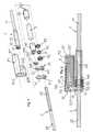
figures 1 à 6 représentent un premier mode de réalisation préféré du dispositif suivant l'invention plus particulièrement adapté à l'implantation à la surface des os, par exemple le long de la colonne vertébrale, de la mâchoire ou entre des côtes. Lafigure 1 est une vue éclatée en perspective de ce mode de réalisation. Lafigure 2 en est une vue en coupe passant par les axes de rotation dudit aimant permanent et de translation de ladite seconde partie par rapport à ladite première partie et dans lequel ledit dispositif est représenté dans sa position raccourcie. Lesfigures 3 à 6 sont des vues suivant l'axe de rotation dudit aimant permanent dans lesquelles le dispositif est présenté sans certains de ses composants pour laisser apparaître ledit levier dans quatre états différents en présence d'une source de champ magnétique placée à l'extérieur de l'organisme. - Les
figures 7 à 12 représentent un second mode de réalisation préféré du dispositif suivant l'invention plus particulièrement adapté à l'implantation dans le canal médullaire d'un os long pour réaliser un allongement ou un transport osseux. Lesfigures 7 et 8 sont des vues éclatées en perspective de ce second mode de réalisation suivant deux angles différents. Lesfigures 9 et 10 en sont des vues en coupe passant par l'axe de rotation dudit aimant permanent. Lafigure 9 représente ledit second mode de réalisation préféré du dispositif suivant l'invention dans sa position initiale, lafigure 10 le représente en fin d'allongement. Lesfigures 11 et 12 sont des coupes dudit second mode de réalisation préféré passant par ledit levier et montrant deux états dudit dispositif en présence d'une source de champ magnétique placée à l'extérieur de l'organisme. - Les
figures 13 et 14 représentent un troisième mode de réalisation préféré du dispositif suivant l'invention particulièrement utile quand l'importance de la force d'allongement produite prime sur l'ergonomie de commande. Lafigure 13 représente en perspective un éclaté dudit troisième mode de réalisation. Lafigure 14 représente une coupe dudit troisième mode de réalisation préféré passant par l'axe de rotation dudit aimant permanent.
- The
Figures 1 to 6 represent a first preferred embodiment of the device according to the invention more particularly suitable for implantation on the surface of the bones, for example along the spine, the jaw or between ribs. Thefigure 1 is an exploded perspective view of this embodiment. Thefigure 2 is a sectional view through the axes of rotation of said permanent magnet and translation of said second portion relative to said first portion and wherein said device is shown in its shortened position. TheFigures 3 to 6 are views along the axis of rotation of said permanent magnet in which the device is presented without some of its components to reveal said lever in four different states in the presence of a magnetic field source placed outside the body . - The
Figures 7 to 12 represent a second preferred embodiment of the device according to the invention more particularly adapted to the implantation in the medullary canal of a long bone to achieve elongation or bone transport. TheFigures 7 and 8 are exploded perspective views of this second embodiment from two different angles. TheFigures 9 and 10 are sectional views through the axis of rotation of said permanent magnet. Thefigure 9 represents said second preferred embodiment of the device according to the invention in its initial position, thefigure 10 represents him in the end elongation. TheFigures 11 and 12 are sections of said second preferred embodiment passing through said lever and showing two states of said device in the presence of a magnetic field source placed outside the body. - The
Figures 13 and 14 represent a third preferred embodiment of the device according to the invention particularly useful when the importance of the elongation force produced takes precedence over the ergonomics of control. Thefigure 13 represents in perspective an exploded view of said third embodiment. Thefigure 14 represents a section of said third preferred embodiment passing through the axis of rotation of said permanent magnet.
Il est bien précisé que, sur les figures, les mêmes références désignent les mêmes éléments, quelle que soit la figure sur laquelle elles apparaissent et quelle que soit la forme de représentation de ces éléments. De même, si un élément n'est pas spécifiquement référencé sur l'une des figures pour ne pas surcharger cette dernière, sa référence peut être aisément retrouvée en se reportant à une autre figure.It is clear that in the figures, the same references designate the same elements, whatever the figure on which they appear and regardless of the form of representation of these elements. Similarly, if an element is not specifically referenced in one of the figures so as not to overload the latter, its reference can be easily found by referring to another figure.
Les lignes cachées sont représentées en pointillés dans toutes les figures sauf dans les
Le demandeur tient aussi à préciser que les figures représentent plusieurs modes de réalisation préférés du dispositif selon l'invention mais qu'il existe d'autres modes de réalisation qui répondent à la définition de cette invention.The applicant also wishes to clarify that the figures represent several preferred embodiments of the device according to the invention but that there are other embodiments that meet the definition of this invention.
Il précise en outre que, lorsque que, selon la définition de l'invention, le dispositif suivant l'invention comporte « au moins un » élément ayant une fonction donnée, le mode de réalisation décrit peut comporter plusieurs de ces éléments.It further specifies that, when, according to the definition of the invention, the device according to the invention comprises "at least one" element having a given function, the embodiment described may comprise several of these elements.
Il précise aussi que si les modes de réalisation de l'objet selon l'invention tels qu'illustrés comportent plusieurs éléments de fonctions identiques et que si, dans la description, il n'est pas spécifié que l'objet selon cette invention doit obligatoirement comporter un nombre particulier de ces éléments, l'objet de l'invention pourra être défini comme comportant « au moins un » de ces éléments.It also specifies that if the embodiments of the object according to the invention as illustrated have several elements of identical functions and if, in the description, it is not specified that the object according to this invention must obligatorily include a particular number of these elements, the object of the invention may be defined as having "at least one" of these elements.
Tous les modes de réalisation du dispositif selon l'invention sont constitués:
d'une première partie 1 qui comprend des premiers moyens11 de liaison à l'organisme,- d'une seconde partie2 qui comprend des seconds moyens21 de liaison à l'organisme et montée coulissante par rapport à ladite première partie1,
- d'un aimant permanent3
- de moyens de liaison entre ledit aimant permanent3 et ladite première partie 1 qui laissent audit aimant permanent3 un degré de liberté en rotation sensiblement autour d'un de ses axes principaux d'inertie perpendiculaire à sa direction d'aimantation,
un arbre d'entrée 41,- de moyens démultiplicateurs pour transformer les mouvements dudit aimant permanent 3 en rotation dudit arbre d'entrée41 alternativement dans un premier sens et /ou dans le sens opposé avec un rapport de réduction entre la rotation dudit arbre d'entrée41 et celle dudit aimant permanent3 et, dans les
Figures 13 et 14 , tels qu'un changement de sens de la rotation dudit aimant permanent3 entraîne le changement de sens de la rotation dudit arbre d'entrée41, - un arbre de sortie42,
- des moyens de roue
libre 43 aptes à entraîner ledit arbre de sortie42 dans ledit premier sens quand ledit arbre d'entrée41 tourne dans ledit premier sens, - des moyens de maintien44 pour empêcher la rotation dudit arbre de sortie42 dans le sens opposé audit premier sens,
- et des moyens de transmission pour que la rotation dudit arbre de sortie42 entraîne le déplacement de ladite seconde partie 2 par rapport à ladite première partie1.
- a
first part 1 which comprises first means11 of binding to the body, - a
second part 2 which comprises second means21 for binding to the body and slidably mounted relative to saidfirst part 1, - of a
permanent magnet 3 - connecting means between said
permanent magnet 3 and saidfirst part 1 which leave said permanent magnet3 a degree of freedom in rotation substantially around one of its main axes of inertia perpendicular to its direction of magnetization, - an
input shaft 41, - of multiplier means for transforming the movements of said
permanent magnet 3 in rotation of saidinput shaft 41 alternately in one direction and / or in the opposite direction with a reduction ratio between the rotation of saidinput shaft 41 and that saidpermanent magnet 3 and, inFigures 13 and 14 , such that a change of direction of the rotation of saidpermanent magnet 3 causes the direction of rotation of saidinput shaft 41 to change, - an
output shaft 42, - freewheel means43 able to drive said
output shaft 42 in said first direction when saidinput shaft 41 rotates in said first direction, - holding means44 for preventing the rotation of said
output shaft 42 in the opposite direction to said first direction, - and transmission means for rotation of said
output shaft 42 to cause saidsecond portion 2 to move relative to saidfirst portion 1.
En outre, dans toutes les formes de réalisation préférées représentées sur les
Dans le premier mode de réalisation préféré du dispositif représenté sur les
L'aimant permanent3 est cylindrique, aimanté diamétralement et collé, par exemple à l'aide d'une colle silicone, à l'intérieur de deux premier31 et second32 capuchons tête-bêches qui, à l'extrémité opposée à celle dans laquelle est inséré ledit aimant permanent3, sont respectivement prolongés, par un premier axe311 qui matérialise l'axe de rotation dudit aimant permanent3 puis par un axe excentrique52, pour ledit premier capuchon31, et par un second axe321 qui matérialise l'axe de rotation dudit aimant permanent3 seulement, pour ledit second capuchon32.The
Un carter34 comportant deux première343 et seconde344 cavités cylindriques parallèles, reçoit dans ladite première cavité343 l'assemblage des deux premier31 et second32 capuchons et dudit aimant permanent3, ledit second axe321 dudit second capuchon32 en premier qui vient se loger dans un perçage341 en fond de ladite première cavité cylindrique343. Une rondelle33 dont le diamètre extérieur correspond au diamètre intérieur de ladite première cavité cylindrique343 et le diamètre intérieur à celui dudit premier axe311 vient se placer autour dudit premier axe311 et fait office de palier.A
Ladite seconde cavité cylindrique344 dudit carter34 reçoit à travers un perçage d'assemblage342 situé du côté où est placé ledit second axe321 dudit second capuchon32 l'extrémité tubulaire de ladite première partie1 dudit premier mode de réalisation préféré du dispositif suivant l'invention. Une surface cylindrique13 de ladite première partie1 de diamètre légèrement supérieur au diamètre dudit perçage d'assemblage342 bloque ladite première partie1 dans ledit carter de manière à ce que seul émerge dans ladite seconde cavité cylindrique344 une surface cylindrique de friction14 située à l'extrémité de ladite première partie1.Said second cylindrical cavity344 of said
Les deux capuchons31, 32, le carter34 et ladite rondelle33 constituent ainsi les moyens de liaison entre ledit aimant permanent3 et ladite première partie1 qui laissent audit aimant permanent 3 un degré de liberté en rotation sensiblement autour d'un de ses axes principaux d'inertie perpendiculaire à sa direction d'aimantation.The two
Du côté opposé à celui dans lequel elle reçoit ladite première partie1, ladite seconde cavité cylindrique344 dudit carter34 reçoit, dans l'ordre et emboîtés les uns derrière les autres, un ressort de maintien44, un écrou constituant ledit arbre de sortie42, un ressort de roue libre d'entraînement43 puis ledit arbre d'entrée41 constitué d'un segment de tube dont l'intérieur411 est apte à coulisser et tourner sur ladite vis62 et dont la surface extérieure est apte à coopérer avec ledit ressort de roue libre d'entraînement43 qui coopère aussi avec une surface analogue située sur ledit écrou42 pour constituer lesdits moyens de roue libre43 aptes à entraîner ledit arbre de sortie42 dans ledit premier sens quand ledit arbre d'entrée41 tourne dans ledit premier sens.On the side opposite to that in which it receives said
Ledit ressort de maintien44 coopère avec ladite surface cylindrique de friction14 située à l'extrémité de ladite première partie 1 et une surface analogue située sur ledit écrou42 pour constituer lesdits moyens de maintien pour empêcher la rotation dudit arbre de sortie42 dans le sens opposé audit premier sens.Said holding
Le détail et le fonctionnement de ce système à ressorts de friction est entièrement décrit dans le document
Ledit écrou42 coopère, à travers son filetage intérieur61, avec la vis62 constituant lesdits moyens de transmission pour que la rotation dudit arbre de sortie42 entraîne le déplacement de ladite seconde partie2 par rapport à ladite première partie1.Said
Un levier51 solidaire dudit arbre d'entrée41 dont il partage l'axe de rotation, constitué dans ce premier mode de réalisation préféré du dispositif par ladite vis62, comporte une gorge d'appui511 dont la largeur est supérieure ou égale au diamètre dudit axe excentrique52 avec lequel elle coopère pour constituer lesdits moyens démultiplicateurs pour transformer les mouvements dudit aimant permanent3 en rotation dudit arbre d'entrée41 alternativement dans un premier sens et dans le sens opposé avec un rapport de réduction entre la rotation dudit arbre d'entrée41 et celle dudit aimant permanent3 et tels qu'un changement de sens de la rotation dudit aimant permanent3 entraîne le changement de sens de la rotation dudit arbre d'entrée41,A
Une pièce d'obturation71 comprenant un perçage711 pour laisser passer ladite seconde partie 2 ferme le carter une fois le reste de l'assemblage achevé.A
Le fonctionnement de ces dits moyens démultiplicateurs est détaillé sur les
On se réfère maintenant aux
Sensiblement à l'extrémité opposée à ladite première extrémité, au moins un perçage formant un angle compris entre 30 et 90° par rapport à l'axe dudit tube10 constitue lesdits premiers moyens11 de liaison à l'organisme. Ladite seconde partie2 est sensiblement un cylindre20 apte à coopérer avec le petit diamètre dudit tube10. Lesdits seconds moyens21 de liaison à l'organisme sont constitués d'au moins un perçage sensiblement perpendiculaire à l'axe dudit cylindre20. Des découpes longitudinales oblongues16 sont pratiquées dans ledit tube10 pour permettre le verrouillage dans lesdits seconds moyens de liaison21 et l'allongement ultérieur.Substantially at the end opposite to said first end, at least one piercing forming an angle of between 30 and 90 ° with respect to the axis of said
Comme dans ledit premier mode préféré de réalisation du dispositif suivant l'invention, l'aimant permanent3 est cylindrique, aimanté diamétralement et collé, par exemple à l'aide d'une colle silicone, à l'intérieur de deux premier31 et second32 capuchons tête-bêches qui, à l'extrémité opposée à celle dans laquelle est inséré ledit aimant permanent3, sont respectivement prolongés, par un premier axe311 qui matérialise l'axe de rotation dudit aimant permanent3 puis par un axe excentrique52, pour ledit premier capuchon31, et par un second axe321 qui matérialise l'axe de rotation dudit aimant permanent3 seulement, pour ledit second capuchon32. En outre, un levier51 solidaire d'un arbre d'entrée41 dont il partage l'axe de rotation, comporte une gorge d'appui511 dont la largeur est supérieure ou égale, mais préférentiellement égale dans ce second mode de réalisation préféré, au diamètre dudit axe excentrique52 avec lequel elle coopère pour constituer lesdits moyens démultiplicateurs.As in said first preferred embodiment of the device according to the invention, the
L'arbre de sortie42 comporte deux surfaces cylindriques destinées, l'une422 à recevoir ledit ressort de roue libre d'entraînement43, l'autre423 à recevoir ledit ressort de maintien44 et, accolé à la première, un axe421 qui constitue l'axe de rotation dudit arbre d'entrée41 et, accolée à la seconde, une vis61 qui coopère avec un taraudage62 parallèle à l'axe de ladite seconde partie2 pour constituer lesdits moyens de transmission pour que la rotation dudit arbre de sortie42 entraîne le déplacement de ladite seconde partie2 par rapport à ladite première partie1.The
Un support36 dont la surface extérieure est essentiellement cylindrique et apte à coopérer avec ladite cavité cylindrique15, à l'exception d'une protubérance364 qui est apte à coopérer avec ladite gorge intérieure longitudinale151 dudit tube10 pour assurer le blocage en rotation dudit support36 par rapport audit tube10, reçoit, en les maintenant dans une disposition relative adaptée :
- ledit
premier axe 311 auquel il sert de palier dans unpremier perçage 361 axial, l'axe 421 dudit arbre de sortie42 dans unsecond perçage 362 parallèle auditpremier perçage 361, ledit arbre d'entrée41 ayant été préalablement enfilé sur cetaxe 421,- le levier51 dans un troisième perçage363 perpendiculaire aux dits premier361 et second362 perçages, la surface dudit troisième perçage363 limitant la
rotation dudit levier 51 dont les extrémités512et 513 viennent respectivement en butée sur ledit troisième perçage363 quand le levier51 tourne dans ledit premier sens ou tourne dans le sens opposé audit premier sens. L'ensemble constituant des premiers moyens de butée dans un sens et des seconds moyens de butée dans le sens opposé pour limiter la rotation dudit aimant permanent 3 à un secteur d'angle inférieur à 180°, si les dimensions dudit levier51 et dudit troisième perçage363 sont convenablement choisies.
- said
first axis 311 which it serves as a bearing in a firstaxial bore 361 , - the
axis 421 of saidoutput shaft 42 in asecond bore 362 parallel to said first bore361, saidinput shaft 41 having been previously threaded on thisaxis 421, - the
lever 51 in athird bore 363 perpendicular to said first361 and second362 bores, the surface of saidthird hole 363 limiting the rotation of saidlever 51 whose ends512 and513 respectively abut on saidthird bore 363 when thelever 51 rotates in said first direction or turns in the opposite direction to said first direction. The assembly constituting first abutment means in one direction and second abutment means in the opposite direction to limit the rotation of saidpermanent magnet 3 to an angle sector less than 180 °, if the dimensions of saidlever 51 and said third piercing363 are suitably selected.
Le rapport de réduction de ce second mode préféré de réalisation du dispositif suivant l'invention est fonction de la distance entre ledit premier perçage361 et ledit second perçage362, d'une part, et de l'excentration dudit axe excentrique52, d'autre part.The reduction ratio of this second preferred embodiment of the device according to the invention is a function of the distance between said
Un bouchon35, muni d'un perçage axial351 qui reçoit ledit second axe321 auquel il sert de palier, s'emboîte en force sur ladite première extrémité dudit tube10 par l'intermédiaire d'une surface cylindrique352 de diamètre légèrement supérieur à celui de ladite cavité cylindrique15.A
Une pièce d'appui37 qui prend place au fond de ladite cavité cylindrique15 en butée sur ladite surface annulaire d'appui152 et est bloquée en rotation par le contact de sa surface plane longitudinale373 avec une autre surface plane longitudinale365 dudit support36, porte également une surface cylindrique de friction371 apte à coopérer avec le ressort de maintien44 pour constituer lesdits moyens de maintien pour empêcher la rotation dudit arbre de sortie42 dans le sens opposé audit premier sens. Cette pièce d'appui37 supporte également tout le poids appliqué par le patient sur le clou d'allongement et transféré par l'intermédiaire de ladite seconde partie2, de ladite vis61, qui travaille en traction, et de la partie dudit arbre de sortie42 qui est au contact de ladite pièce d'appui37.A
Le fonctionnement de ce second mode de réalisation préféré du dispositif suivant l'invention est très similaire à celui dudit premier mode de réalisation préféré du dispositif suivant l'invention et ne sera donc pas explicité dans le détail. Les
Lesdites figures représentent des états stables et il faut modifier la position de ladite source de champ magnétique81, par exemple la retourner, pour qu'ils évoluent vers l'état représenté sur l'autre figure.Said figures represent stable states and it is necessary to modify the position of said
Le troisième mode de réalisation préféré du dispositif suivant l'invention représenté sur les
La première partie1 dudit troisième mode de réalisation préféré du dispositif suivant l'invention est sensiblement un cylindre avec une extrémité arrondie qui porte également au moins un perçage sensiblement perpendiculaire à l'axe de ladite première partie 1 et qui constitue lesdits premier moyens11 de liaison à l'organisme. A l'extrémité opposée à ladite extrémité arrondie se trouvent, disposées radialement à la surface dudit cylindre, des ailettes anti-rotation17, et, dans le prolongement dudit cylindre et partageant son axe, une surface cylindrique141 apte à coopérer avec un ressort de44 et un logement cylindrique18 qui débouche à l'extrémité de ladite surface cylindrique141 opposée à celle qui la rattache audit cylindre.The
La seconde partie2 dudit troisième mode de réalisation préféré du dispositif suivant l'invention est un tube entièrement fileté sur sa face interne62 dans lequel ladite première partie1 peut se translater librement mais sans jeu excessif. Des gorges anti-rotation22 aptes à coopérer avec lesdites ailettes anti-rotation17 de ladite première partie 1 de manière à empêcher la rotation de l'une par rapport à l'autre, sont découpées longitudinalement à l'intérieur de ladite seconde partie2. Sensiblement à une extrémité de ladite seconde partie2, au moins un perçage faisant un angle de 30 à 90° avec l'axe constitue lesdits second moyens21 de liaison à l'organisme.The
L'aimant permanent3 est cylindrique, aimanté diamétralement et collé, par exemple à l'aide d'une colle silicone, à l'intérieur d'un capuchon37 qui, à l'extrémité opposée à celle dans laquelle est introduite ledit aimant permanent3 comporte un taraudage371 qui reçoit une vis38 comportant une partie filetée53, ou quatrième surface, et une tête381 et qui est soudée en bout du côté opposé à sa tête381 à l'intérieur dudit capuchon37 avant collage dudit aimant permanent3. Ladite vis38 matérialise l'axe de rotation dudit aimant permanent3 dont elle est totalement solidaire. La tête381 de ladite vis38 est logée dans ledit logement cylindrique18 de ladite première partie1. Son corps est introduit dans le canal central393 débouchant de part et d'autre d'un axe d'assemblage39 qui comporte un corps cylindrique391 dont le diamètre est légèrement supérieur à celui dudit logement cylindrique18 et une tête392 et sur lequel a été préalablement monté dans l'ordre ledit arbre d'entrée41 contre la tête392 puis, ledit ressort de roue libre d'entraînement43, ledit arbre de sortie42 et ledit ressort de maintien44. L'extrémité dudit corps cylindrique391 opposée à ladite tête 392 est assemblée en force dans ledit logement cylindrique18 bloquant en translation mais pas en rotation ladite vis38 et donc ledit aimant permanent3 par rapport à ladite première partie1 et maintenant accolés les uns aux autres les éléments qui ont été préalablement montés sur ledit corps cylindrique391.The
Ledit arbre de sortie42 comporte deux surfaces cylindrique destinées, l'une422 à recevoir ledit ressort de roue libre d'entraînement43, l'autre423 à recevoir ledit ressort de maintien44 et disposées de part et d'autre d'une vis61 apte à coopérer avec l'intérieur taraudé62 de ladite seconde partie2 . Le centre dudit arbre de sortie42 comporte un perçage424 qui permet audit arbre de sortie42 d'être monté libre en rotation sur ledit axe d'assemblage39. Tous ces éléments sont coaxiaux.Said
Ledit arbre d'entrée41 comporte, à une extrémité une surface cylindrique destinée à recevoir ledit ressort de roue libre d'entraînement43 et, à l'autre extrémité, une torsade55, ou sixième surface. Il est également traversé suivant son axe par un perçage411 qui lui permet d'être monté libre en rotation sur ledit axe d'assemblage39.
Ce troisième mode de réalisation préféré du dispositif suivant l'invention comporte en outre une pièce amplificatrice54 sensiblement cylindrique et apte à coulisser dans ladite seconde partie2 et qui comprend des ailettes anti-rotation543 aptes à coopérer avec lesdites gorges anti-rotation22 de ladite seconde partie2, qui est elle-même bloquée en rotation avec ladite première partie, et, à une extrémité, un taraudage541, ou troisième surface, apte à coopérer avec la partie filetée53 de ladite vis38 et, à l'autre extrémité, des surfaces femelles542, ou cinquième surface, aptes à coopérer avec ladite torsade55. Cette pièce amplificatrice54 vient se visser sur ladite partie filetée53 de ladite vis38 après assemblage en force dudit axe d'assemblage39 dans ladite première partie1 et avant vissage dudit capuchon37 sur ladite vis38 et soudure en bout de l'un avec l'autre.This third preferred embodiment of the device according to the invention further comprises an amplifying
Ce troisième mode de réalisation préféré du dispositif suivant l'invention fonctionne de la manière suivante: un champ magnétique tournant créé par la source de champ magnétique placée à l'extérieur de l'organisme met ledit aimant permanent3 en rotation dans un premier sens pour un nombre de tours dont le maximum est imposé par la longueur et le pas de la partie filetée53 de la vis38 ou par l'espace réservé à la pièce amplificatrice54 pour sa translation entre les butées constituées par le capuchon37 d'une part et la tête392 dudit axe d'assemblage39 d'autre part. La rotation dudit aimant permanent3 entraîne celle de ladite vis38 dont il est solidaire et, par l'intermédiaire de la partie filetée53 de cette dernière, qui coopèrent avec le taraudage541 de ladite pièce amplificatrice54 pour constituer ladite seconde liaison hélicoïdale, la translation de ladite pièce amplificatrice54 dans une premier sens de translation. La pièce amplificatrice étant bloquée en rotation par les ailettes anti-rotation543 et coopérant par l'intermédiaire de ses surfaces femelles542 avec ladite torsade55 entraîne ledit arbre d'entrée41 en rotation dans un sens qui dépend bien sûr aussi du sens du pas de ladite torsade55.This third preferred embodiment of the device according to the invention operates as follows: a rotating magnetic field created by the magnetic field source placed outside the body puts said
Puis, ledit aimant permanent3 est mis rotation dans le sens opposé audit premier sens pour un nombre de tours identique à celui effectué dans ledit premier sens, et ledit arbre d'entrée41 retrouve sa position initiale par l'effet du mouvement inverse de toutes les pièces. Pendant ces mouvements, le système de ressorts de frictions fait son travail et entraîne ledit arbre de sortie42 en rotation dans un seul sens ce qui conduit de manière évidente au déplacement de ladite seconde partie2 par rapport à ladite première partie1. On réitère ce cycle autant de fois que nécessaire pour obtenir l'allongement souhaité.Then, said
Le rapport de réduction de ce troisième mode préféré de réalisation du dispositif suivant l'invention est fonction des pas de ladite partie filetée 53 de ladite vis et de ladite torsade55. En outre, le pas de ladite torsade55 doit être suffisamment grand au regard des frottements existants pour que ledit dispositif fonctionne.The reduction ratio of this third preferred embodiment of the device according to the invention is a function of the pitch of said threaded
Dans ce troisième mode de réalisation préféré du dispositif suivant l'invention, il est aussi possible d'intercaler un mécanisme à croix de Malte entre l'aimant permanent3 et la vis53 pour faciliter, si elle est souhaitable, la commande dudit dispositif par rotation d'une source de champ magnétique81 externe à l'organisme autour d'un axe parallèle à l'axe de rotation dudit aimant permanent3 et placé au plus près dudit aimant permanent3. En effet l'utilisation d'une croix de Malte permet que ledit aimant permanent3 n'entraîne l'arbre d'entrée41 que sur une portion de sa rotation pour laquelle le couple qui peut être exercé sur ledit aimant permanent3 par ladite source de champ magnétique81 est élevé grâce à un calage judicieux de la direction d'aimantation dudit aimant permanent3 par rapport à la direction dans laquelle on place la source de champ magnétique81 et à la position de la roue, solidaire dudit aimant permanent3, qui entraîne la croix de Malte, solidaire de ladite vis53, par rapport à ladite croix de Malte. Un bon résultat est obtenu si la bissectrice de la direction d'aimantation dudit aimant permanent3 lorsque ladite roue d'entraînement commence à engrener ladite croix de Malte et la direction d'aimantation dudit aimant permanent3 lorsque ladite roue d'entraînement quitte ladite croix de Malte est sensiblement perpendiculaire à la direction dans laquelle on peut placer ladite source de champ magnétique81 au plus près dudit aimant permanent3.In this third preferred embodiment of the device according to the invention, it is also possible to insert a Maltese cross mechanism between the
Le dispositif suivant l'invention est avantageusement réalisé dans des matériaux résistants mécaniquement et bien tolérés par l'organisme tels des aciers inoxydables comme le 316L, des alliages de titane ou, de préférence, comme des alliages hautes performances à base de chrome et de cobalt comme par exemple le PHYNOX. Ledit aimant permanent3 est avantageusement un aimant néodyme du type de ceux dont la température de Curie est supérieure à 150 °C pour permettre la stérilisation dudit dispositif suivant l'invention par tous moyens et notamment à la vapeur surchauffée à 134°C sans risque de détérioration dudit aimant permanent3.The device according to the invention is advantageously made of mechanically resistant and well-tolerated materials such as stainless steels such as 316L, titanium alloys or, preferably, as high-performance alloys based on chromium and cobalt. as for example the PHYNOX. Said
Avantageusement les surfaces soumises à un frottement dudit dispositif suivant l'invention reçoivent un traitement de surface diminuant leur coefficient de frottement à base de carbone amorphe diamantin ou de de bisulfure de tungstène par exemple.Advantageously, the surfaces subjected to friction of said device according to the invention receive a surface treatment decreasing their coefficient of friction based on amorphous diamondin carbon or tungsten disulphide, for example.
L'utilisation d'un aimant permanent3 cylindrique aimanté diamétralement a été décrite et est préférée mais toute géométrie d'aimant est envisageable en particulier parallélépipédique, à section hexagonale etc... avec toute direction d'aimantation.The use of a diametrically magnetized cylindrical
Le dispositif suivant l'invention s'implante et se fixe à l'intérieur de l'organisme de manière tout à fait connue et similaire à ses homologues non dotés d'un mécanisme d'allongement.The device according to the invention is implanted and fixed inside the body in a manner quite known and similar to its counterparts without an elongation mechanism.
La présente invention est particulièrement utile pour la réalisation de tout type de dispositif d'allongement intra-corporel tels que des prothèses osseuses à croissances, des clous médullaires d'allongement ou de transport osseux, des tiges rachidiennes de distraction ou de compression ou des distracteurs osseux ou inter-costaux. Elle peut aussi servir à la réalisation de plaques à croissance pour la correction de déformations osseuses ou de pompes implantées pour la diffusion progressive et contrôlée de substances dans l'organisme et, plus largement, peut permettre la réalisation de tout type de dispositif dont on souhaite pouvoir modifier la géométrie de manière graduelle et contrôlée sans contact direct.The present invention is particularly useful for the realization of any type of intracorporeal elongation device such as growing prostheses of bone, medullary nails for elongation or bone transport, spinal rods of distraction or compression or distractors bone or inter-ribal. It can also be used for the production of growth plates for the correction of bone deformations or implanted pumps for the gradual and controlled diffusion of substances in the body and, more broadly, can allow the realization of any type of device which is desired. ability to modify the geometry in a gradual and controlled manner without direct contact.
Claims (8)
- Intracorporeal elongation device composed of a first part (1), which comprises first means (11) of connection to the body, a second part (2), which comprises second means (21) of connection to the body and is mounted so as to slide relative to the first part (1), and a permanent magnet (3), the device further including:- means of connection between the permanent magnet (3) and the first part (1) allowing the permanent magnet (3) a degree of freedom of rotation substantially about one of its main axes of inertia perpendicular to its direction of magnetization,- an input shaft (41),- an output shaft (42),- transmission means such that the rotation of the output shaft (42) causes the displacement of the second part (2) relative to the first part (1),the device beingcharacterized in that it includes:- step-down gears transforming the movements of the permanent magnet (3) into rotation of the input shaft (41), alternately in a first direction and in the opposite direction, with a gear reduction ratio between the rotation of the input shaft (41) and that of the permanent magnet (3),- free-wheel means (43) for driving the output shaft (42) in the first direction when the input shaft (41) turns in the first direction,- retaining means (44) for preventing the rotation of the output shaft (42) in the direction opposite to the first direction when the input shaft (41) turns in the direction opposite to the first direction.
- Intracorporeal elongation device according to Claim 1,characterized in that the transmission means are a first helical connection between a first surface (61) integral with the output shaft (42) and a second surface (62) integral with the second part (2).
- Intracorporeal elongation device according to Claim 1,characterized in that the step-down gears are formed by a lever (51) integral with the input shaft (41), with which it shares the axis of rotation, and means of connection between a first supporting surface (52), integral with the permanent magnet (3) and remote from its axis of rotation, and a second supporting surface (511) integral with the end of the lever (51) farthest from the axis of rotation common to the lever (51) and to the input shaft (41).
- Intracorporeal elongation device according to Claim 3,characterized in that the rotation of the permanent magnet (3) is limited to an angle sector of less than 180° by first abutment means (512) in one direction, and by second abutment means (513) in the opposite direction.
- Intracorporeal elongation device according to either of Claims 3 and 4,characterized in that the means of connection between the first supporting surface (52) and the second supporting surface (511) include a clearance that permits the rotation of the permanent magnet (3), without driving the lever (51), on two sectors substantially opposite to each other relative to the axis of rotation of the permanent magnet (3).
- Intracorporeal elongation device composed of a first part (1), which comprises first means (11) of connection to the body, a second part (2), which comprises second means (21) of connection to the body and is mounted so as to slide relative to the first part (1), and a permanent magnet (3), the device further including:- means of connection between the permanent magnet (3) and the first part (1) allowing the permanent magnet (3) a degree of freedom of rotation substantially about one of its main axes of inertia perpendicular to its direction of magnetization,- an input shaft (41),- step-down gears transforming the movements of the permanent magnet (3) into rotation of the input shaft (41), alternately in a first direction or in the opposite direction, with a gear reduction ratio between the rotation of the input shaft (41) and that of the permanent magnet (3) and such that a change of direction of rotation of the permanent magnet (3) causes the change of direction of rotation of the input shaft (41),- an output shaft (42),- transmission means such that the rotation of the output shaft (42) causes the displacement of the second part (2) relative to the first part (1),The device beingcharacterized in that it includes:- free-wheel means (43) for driving the output shaft (42) in the first direction when the input shaft (41) turns in the first direction,- retaining means (44) for preventing the rotation of the output shaft (42) in the direction opposite to the first direction when the input shaft (41) turns in the direction opposite to the first direction.
- Intracorporeal elongation device according to Claim 6,characterized in that the step-down gears are formed by an amplifying component (54) of the input shaft (41), with which it shares the axis of rotation, and means of connection between a female surface (542), integral with the permanent magnet (3), and a torsade (55) integral with the amplifying component (54).
- Intracorporeal elongation device according to Claim 6,characterized in that the step-down gears are formed by an amplifying component (54) mounted in translation and blocked in rotation relative to the first part (1) and comprising a third surface (541) in second helical connection to a fourth surface (53) integral with the permanent magnet, and a fifth surface (542) in third helical connection to a sixth surface (55) integral with the input shaft (41), the axes of rotation of the permanent magnet (3), of the second and third helical connections and of the input shaft (41) being coincident, the pitches of the second and third helical connections being in the gear reduction ratio of the step-down gears, and the pitch of the second helical connection being sufficiently great relative to the coefficient of friction of the second helical connection to permit the functioning of the step-down gears.
Applications Claiming Priority (2)
| Application Number | Priority Date | Filing Date | Title |
|---|---|---|---|
| FR0608678AFR2906453B1 (en) | 2006-10-03 | 2006-10-03 | INTRA-BODY LIFTING DEVICE WITH PERMANENT MAGNET. |
| PCT/FR2007/001612WO2008040880A2 (en) | 2006-10-03 | 2007-10-02 | Intracorporeal elongation device with a permanent magnet |
Publications (2)
| Publication Number | Publication Date |
|---|---|
| EP2068724A2 EP2068724A2 (en) | 2009-06-17 |
| EP2068724B1true EP2068724B1 (en) | 2016-11-23 |
Family
ID=38110351
Family Applications (1)
| Application Number | Title | Priority Date | Filing Date |
|---|---|---|---|
| EP07848311.2AActiveEP2068724B1 (en) | 2006-10-03 | 2007-10-02 | Intracorporeal elongation device with a permanent magnet |
Country Status (6)
| Country | Link |
|---|---|
| US (1) | US8632548B2 (en) |
| EP (1) | EP2068724B1 (en) |
| CN (1) | CN101568309B (en) |
| ES (1) | ES2616099T3 (en) |
| FR (1) | FR2906453B1 (en) |
| WO (1) | WO2008040880A2 (en) |
Families Citing this family (86)
| Publication number | Priority date | Publication date | Assignee | Title |
|---|---|---|---|---|
| US7955357B2 (en) | 2004-07-02 | 2011-06-07 | Ellipse Technologies, Inc. | Expandable rod system to treat scoliosis and method of using the same |
| US8016837B2 (en)* | 2006-04-06 | 2011-09-13 | Synthes Usa, Llc | Remotely adjustable tissue displacement device |
| WO2007118177A2 (en) | 2006-04-06 | 2007-10-18 | Synthes (U.S.A.) | Remotely adjustable tissue displacement device |
| FR2901991B1 (en)* | 2006-06-13 | 2021-07-09 | Arnaud Andre Soubeiran | INTRACORPAL EXTENSION DEVICE MOUNTED IN TENSILE SCREW |
| FR2906453B1 (en) | 2006-10-03 | 2009-03-06 | Arnaud Andre Soubeiran | INTRA-BODY LIFTING DEVICE WITH PERMANENT MAGNET. |
| US7862502B2 (en) | 2006-10-20 | 2011-01-04 | Ellipse Technologies, Inc. | Method and apparatus for adjusting a gastrointestinal restriction device |
| FR2916622B1 (en)* | 2007-05-28 | 2009-09-04 | Arnaud Andre Soubeiran | IMPLANTABLE DISTRACTOR WITH MODIFIABLE LENGTH WITHOUT REOPERATION IN J-SHAPE |
| US20090112262A1 (en) | 2007-10-30 | 2009-04-30 | Scott Pool | Skeletal manipulation system |
| US11202707B2 (en) | 2008-03-25 | 2021-12-21 | Nuvasive Specialized Orthopedics, Inc. | Adjustable implant system |
| US11241257B2 (en)* | 2008-10-13 | 2022-02-08 | Nuvasive Specialized Orthopedics, Inc. | Spinal distraction system |
| AU2009310439B2 (en)* | 2008-10-31 | 2016-05-26 | Implantica Patent Ltd. | Device and method for bone adjustment with anchoring function |
| US8382756B2 (en) | 2008-11-10 | 2013-02-26 | Ellipse Technologies, Inc. | External adjustment device for distraction device |
| US8197490B2 (en) | 2009-02-23 | 2012-06-12 | Ellipse Technologies, Inc. | Non-invasive adjustable distraction system |
| US9622792B2 (en) | 2009-04-29 | 2017-04-18 | Nuvasive Specialized Orthopedics, Inc. | Interspinous process device and method |
| JP5751642B2 (en) | 2009-09-04 | 2015-07-22 | エリプス テクノロジーズ, インク.Ellipse Technologies, Inc. | Bone growth apparatus and method |
| FR2949662B1 (en)* | 2009-09-09 | 2011-09-30 | Arnaud Soubeiran | INTRA-BODY DEVICE FOR MOVING TISSUE |
| US8568457B2 (en)* | 2009-12-01 | 2013-10-29 | DePuy Synthes Products, LLC | Non-fusion scoliosis expandable spinal rod |
| US8777947B2 (en) | 2010-03-19 | 2014-07-15 | Smith & Nephew, Inc. | Telescoping IM nail and actuating mechanism |
| CN102917659B (en)* | 2010-03-19 | 2016-04-20 | 史密夫和内修有限公司 | Telescoping Intramedullary Nails and Actuation Mechanisms |
| FR2957776B1 (en)* | 2010-03-23 | 2013-02-15 | Arnaud Andre Soubeiran | DEVICE FOR MOVING TISSUES INSIDE THE ORGANISM, ESPECIALLY BONE TISSUES, WITH FIXED TRACTION SCREWS AND ROTATING NUT |
| US8641723B2 (en) | 2010-06-03 | 2014-02-04 | Orthonex LLC | Skeletal adjustment device |
| FR2961386B1 (en)* | 2010-06-21 | 2012-07-27 | Arnaud Soubeiran | INTRA-MEDALLIC DEVICE FOR THE RELATIVE MOVEMENT OF TWO LOCKED BONE PORTIONS BY THE MEDULLARY CHANNEL. |
| US9248043B2 (en) | 2010-06-30 | 2016-02-02 | Ellipse Technologies, Inc. | External adjustment device for distraction device |
| WO2012021378A2 (en)* | 2010-08-09 | 2012-02-16 | Ellipse Technologies, Inc. | Maintenance feature in magnetic implant |
| US8282671B2 (en) | 2010-10-25 | 2012-10-09 | Orthonex | Smart device for non-invasive skeletal adjustment |
| US8721566B2 (en) | 2010-11-12 | 2014-05-13 | Robert A. Connor | Spinal motion measurement device |
| AU2011331999B2 (en) | 2010-11-22 | 2016-07-21 | Synthes Gmbh | Non-fusion scoliosis expandable spinal rod |
| WO2012112396A2 (en) | 2011-02-14 | 2012-08-23 | Ellipse Technologies, Inc. | Device and method for treating fractured bones |
| BR112013029376A2 (en) | 2011-05-16 | 2017-01-31 | Smith & Nephew Inc | skeleton extension measurement |
| DE102011053638A1 (en)* | 2011-09-15 | 2013-03-21 | Wittenstein Ag | Mark Nagel |
| US10743794B2 (en) | 2011-10-04 | 2020-08-18 | Nuvasive Specialized Orthopedics, Inc. | Devices and methods for non-invasive implant length sensing |
| US10016220B2 (en) | 2011-11-01 | 2018-07-10 | Nuvasive Specialized Orthopedics, Inc. | Adjustable magnetic devices and methods of using same |
| US10166048B2 (en)* | 2011-11-02 | 2019-01-01 | Tenzin Llc | Translational instrumentation for spondylolisthesis and scoliosis reduction |
| US10016226B2 (en)* | 2011-12-12 | 2018-07-10 | Children's Hospital Medical Center Of Akron | Noninvasive device for adjusting fastener |
| US9949761B2 (en) | 2011-12-12 | 2018-04-24 | Children's Hospital Medical Center Of Akron | Noninvasive device for adjusting fastener |
| US10709482B2 (en)* | 2012-05-30 | 2020-07-14 | Globus Medical, Inc. | Laminoplasty system |
| US9427261B2 (en)* | 2012-06-13 | 2016-08-30 | Warsaw Orthopedic, Inc. | Spinal correction system and method |
| US20130338714A1 (en) | 2012-06-15 | 2013-12-19 | Arvin Chang | Magnetic implants with improved anatomical compatibility |
| CN102895048B (en)* | 2012-09-14 | 2016-12-21 | SAMBU Medical株式会社 | The human body artificial skelecton of non-operative treatment extending length |
| US9044281B2 (en) | 2012-10-18 | 2015-06-02 | Ellipse Technologies, Inc. | Intramedullary implants for replacing lost bone |
| EP2911616B1 (en) | 2012-10-29 | 2020-10-07 | NuVasive Specialized Orthopedics, Inc. | Adjustable devices for treating arthritis of the knee |
| US9179938B2 (en) | 2013-03-08 | 2015-11-10 | Ellipse Technologies, Inc. | Distraction devices and method of assembling the same |
| CN104095695B (en)* | 2013-04-09 | 2017-02-08 | 上海交通大学医学院附属第九人民医院 | Magnetic joint prosthesis |
| US10226242B2 (en) | 2013-07-31 | 2019-03-12 | Nuvasive Specialized Orthopedics, Inc. | Noninvasively adjustable suture anchors |
| US9801734B1 (en) | 2013-08-09 | 2017-10-31 | Nuvasive, Inc. | Lordotic expandable interbody implant |
| US10751094B2 (en) | 2013-10-10 | 2020-08-25 | Nuvasive Specialized Orthopedics, Inc. | Adjustable spinal implant |
| EP2915496B2 (en)* | 2014-03-06 | 2024-06-26 | MPS Micro Precision Systems AG | Implantable device |
| CN106456215B (en) | 2014-04-28 | 2020-04-10 | 诺威适骨科专科公司 | External adjustment device for adjusting a medical implant |
| DE102014112573A1 (en)* | 2014-09-01 | 2016-03-03 | Wittenstein Ag | Mark Nagel |
| US9931138B2 (en)* | 2014-10-15 | 2018-04-03 | Globus Medical, Inc. | Orthopedic extendable rods |
| KR102588501B1 (en) | 2014-10-23 | 2023-10-11 | 누베이시브 스페셜라이즈드 오소페딕스, 인크. | Remotely adjustable interactive bone reshaping implant |
| ES2908064T3 (en) | 2014-12-26 | 2022-04-27 | Nuvasive Specialized Orthopedics Inc | distraction systems |
| US10238427B2 (en) | 2015-02-19 | 2019-03-26 | Nuvasive Specialized Orthopedics, Inc. | Systems and methods for vertebral adjustment |
| US10070854B2 (en)* | 2015-05-14 | 2018-09-11 | Ankon Medical Technologies (Shanghai), Ltd. | Auxiliary apparatus for minimally invasive surgery and method to use the same |
| US11259844B2 (en)* | 2015-10-05 | 2022-03-01 | Globus Medical Inc. | Growing rod for treating spinal deformities and method for using same |
| US10226281B2 (en)* | 2015-10-05 | 2019-03-12 | Globus Medical, Inc. | Growing rod for treating spinal deformities and method for using same |
| BR112018007347A2 (en) | 2015-10-16 | 2018-10-23 | Nuvasive Specialized Orthopedics, Inc. | adjustable devices for the treatment of knee arthritis |
| CN108601611B (en) | 2015-12-10 | 2021-11-02 | 诺威适骨科专科公司 | External adjustment device for stretcher |
| BR112018015504A2 (en) | 2016-01-28 | 2018-12-18 | Nuvasive Specialized Orthopedics, Inc. | bone transport systems |
| WO2017139548A1 (en) | 2016-02-10 | 2017-08-17 | Nuvasive Specialized Orthopedics, Inc. | Systems and methods for controlling multiple surgical variables |
| US10888357B2 (en) | 2016-02-29 | 2021-01-12 | Warsaw Orthopedic, Inc. | Spinal implant system and method |
| WO2017206691A1 (en)* | 2016-05-31 | 2017-12-07 | 重庆西山科技股份有限公司 | Magnet-driven medical handle |
| KR101891194B1 (en)* | 2016-06-24 | 2018-08-23 | (주)시지바이오 | Length adjustable rod for fixing the vertebra |
| WO2018102101A2 (en)* | 2016-11-09 | 2018-06-07 | Children's Hospital Medical Center Of Akron | Distraction osteogenesis system |
| WO2018144386A1 (en)* | 2017-02-02 | 2018-08-09 | Smith & Nephew, Inc. | Implantable bone adjustment devices |
| CN107280747B (en)* | 2017-07-25 | 2024-04-02 | 魏巍 | Intramedullary pin |
| US10722278B2 (en)* | 2017-10-06 | 2020-07-28 | Smith & Nephew, Inc. | Implantable bone adjustment devices |
| CN108904026A (en)* | 2018-08-13 | 2018-11-30 | 北京大学人民医院 | It can be used for the electromagnetic drive intramedullary needle of bone carrying |
| US11116554B2 (en)* | 2018-08-14 | 2021-09-14 | Smith & Nephew, Inc. | Implantable bone adjustment device with improved strength |
| US12121265B2 (en)* | 2019-01-03 | 2024-10-22 | Globus Medical Inc. | Growing rod for treating spinal deformities and method for using same |
| JP2022519380A (en) | 2019-02-07 | 2022-03-23 | ニューベイシブ スペシャライズド オーソペディックス,インコーポレイテッド | Ultrasonic communication in medical devices |
| US11589901B2 (en) | 2019-02-08 | 2023-02-28 | Nuvasive Specialized Orthopedics, Inc. | External adjustment device |
| CN111603233A (en)* | 2020-06-15 | 2020-09-01 | 四川大学华西医院 | A kind of bone lengthening intramedullary nail device |
| US12213708B2 (en) | 2020-09-08 | 2025-02-04 | Nuvasive Specialized Orthopedics, Inc. | Remote control module for adjustable implants |
| FR3118404B1 (en)* | 2020-12-30 | 2022-12-16 | Ecole Nat Superieure De Techniques Avancees | Activation tool for a bone expander |
| US20220265326A1 (en) | 2021-02-23 | 2022-08-25 | Nuvasive Specialized Orthopedics, Inc. | Adjustable implant, system and methods |
| US11737787B1 (en) | 2021-05-27 | 2023-08-29 | Nuvasive, Inc. | Bone elongating devices and methods of use |
| CN113520561B (en)* | 2021-07-21 | 2022-08-23 | 南通市第一人民医院 | Positioning device is corrected to vertebra lateral curvature |
| EP4380480A1 (en) | 2021-08-03 | 2024-06-12 | NuVasive Specialized Orthopedics, Inc. | Adjustable implant |
| CN114081685B (en)* | 2021-12-28 | 2024-11-12 | 上海交通大学医学院附属第九人民医院 | Telescopic femoral stem prosthesis |
| CN116138862A (en)* | 2023-03-02 | 2023-05-23 | 北京积水潭医院 | intramedullary extension nail |
| CN116236268B (en)* | 2023-04-11 | 2024-08-20 | 中国医学科学院北京协和医院 | Spinal column correction device and control method for spinal column correction device |
| US20240358418A1 (en)* | 2023-04-25 | 2024-10-31 | Nuvasive Specialized Orthopedics, Inc. | Flat plate mechanisms for bone lengthening |
| EP4529869A1 (en)* | 2023-09-28 | 2025-04-02 | Orthofix S.r.l. | Intramedullary nail for a long bone |
| CN117582263B (en)* | 2024-01-15 | 2024-04-19 | 诺美伊创医疗科技(成都)有限公司 | Medical plane blade |
| CN118161247B (en)* | 2024-05-13 | 2024-07-19 | 汉中市中心医院 | Controllable telescopic thoracolumbar fracture vertebral canal occupation position restorer |
Family Cites Families (19)
| Publication number | Priority date | Publication date | Assignee | Title |
|---|---|---|---|---|
| CH581988A5 (en)* | 1974-04-09 | 1976-11-30 | Messerschmitt Boelkow Blohm | |
| DE8515687U1 (en)* | 1985-05-29 | 1985-10-24 | Aesculap-Werke Ag Vormals Jetter & Scheerer, 7200 Tuttlingen | Distraction device for extension osteotomy |
| WO1996015377A1 (en) | 1994-11-16 | 1996-05-23 | Soubeiran Arnaud Andre | Device for mutually moving two bodies |
| US5704939A (en) | 1996-04-09 | 1998-01-06 | Justin; Daniel F. | Intramedullary skeletal distractor and method |
| NL1004873C2 (en)* | 1996-12-23 | 1998-06-24 | Univ Twente | Device for moving two objects together. |
| US6033412A (en)* | 1997-04-03 | 2000-03-07 | Losken; H. Wolfgang | Automated implantable bone distractor for incremental bone adjustment |
| GB9806999D0 (en)* | 1998-04-02 | 1998-06-03 | Univ Birmingham | Distraction device |
| FR2788625B1 (en) | 1999-01-15 | 2002-11-29 | Signature Sa | CATADIOPTRIC PANEL |
| FR2805451B1 (en)* | 2000-02-29 | 2002-04-19 | Arnaud Andre Soubeiran | IMPROVED DEVICE FOR MOVING TWO BODIES IN RELATION TO ONE ANOTHER, PARTICULARLY FOR REALIZING IMPLANTABLE SYSTEMS IN THE HUMAN BODY |
| GB0009107D0 (en)* | 2000-04-13 | 2000-05-31 | Univ London | Surgical distraction device |
| FR2819394B1 (en) | 2001-01-17 | 2003-06-13 | Arnaud Andre Soubeiran | ELONGATION ROD |
| FR2822050B1 (en) | 2001-03-13 | 2003-07-25 | Arnaud Andre Soubeiran | DEVICE FOR MOVING IN ONE SENSE ON A DIRECTION DELTA A PORTION OF BONE IN RELATION TO ANOTHER |
| FR2843875B1 (en) | 2002-08-30 | 2004-10-08 | Arnaud Andre Soubeiran | IMPLANTABLE DEVICE FOR TRANSFORMING ON DEMAND ALTERNATE COUPLES APPLIED BY MUSCLE FORCE BETWEEN TWO WORKPIECES IN A MOVEMENT OF TWO BODIES RELATIVELY TO ONE ANOTHER |
| US20050261779A1 (en)* | 2003-11-17 | 2005-11-24 | Meyer Rudolf X | Expansible rod-type prosthesis and external magnetic apparatus |
| US7955357B2 (en)* | 2004-07-02 | 2011-06-07 | Ellipse Technologies, Inc. | Expandable rod system to treat scoliosis and method of using the same |
| FR2901991B1 (en) | 2006-06-13 | 2021-07-09 | Arnaud Andre Soubeiran | INTRACORPAL EXTENSION DEVICE MOUNTED IN TENSILE SCREW |
| FR2906453B1 (en) | 2006-10-03 | 2009-03-06 | Arnaud Andre Soubeiran | INTRA-BODY LIFTING DEVICE WITH PERMANENT MAGNET. |
| US7862502B2 (en)* | 2006-10-20 | 2011-01-04 | Ellipse Technologies, Inc. | Method and apparatus for adjusting a gastrointestinal restriction device |
| FR2916622B1 (en) | 2007-05-28 | 2009-09-04 | Arnaud Andre Soubeiran | IMPLANTABLE DISTRACTOR WITH MODIFIABLE LENGTH WITHOUT REOPERATION IN J-SHAPE |
- 2006
- 2006-10-03FRFR0608678Apatent/FR2906453B1/ennot_activeExpired - Fee Related
- 2007
- 2007-10-02EPEP07848311.2Apatent/EP2068724B1/enactiveActive
- 2007-10-02ESES07848311.2Tpatent/ES2616099T3/enactiveActive
- 2007-10-02WOPCT/FR2007/001612patent/WO2008040880A2/enactiveApplication Filing
- 2007-10-02CNCN2007800415027Apatent/CN101568309B/ennot_activeExpired - Fee Related
- 2007-10-02USUS12/444,337patent/US8632548B2/enactiveActive
Also Published As
| Publication number | Publication date |
|---|---|
| WO2008040880A2 (en) | 2008-04-10 |
| FR2906453B1 (en) | 2009-03-06 |
| WO2008040880A3 (en) | 2008-05-22 |
| CN101568309A (en) | 2009-10-28 |
| EP2068724A2 (en) | 2009-06-17 |
| FR2906453A1 (en) | 2008-04-04 |
| ES2616099T3 (en) | 2017-06-09 |
| US8632548B2 (en) | 2014-01-21 |
| CN101568309B (en) | 2012-02-22 |
| US20100049204A1 (en) | 2010-02-25 |
Similar Documents
| Publication | Publication Date | Title |
|---|---|---|
| EP2068724B1 (en) | Intracorporeal elongation device with a permanent magnet | |
| EP2026706B1 (en) | Device for intrabody extension with screws working in traction | |
| EP2371310B1 (en) | Device for displacement of tissue, in particular bone tissue | |
| EP3386404B1 (en) | Assembly of a plate distractor and an activation tool | |
| WO2004019796A1 (en) | Implantable mechanical device with adjustable geometry | |
| EP1294297B1 (en) | Intervertebral linking device | |
| EP2332716B1 (en) | Bulging die device for clips on a machine for making sockets on the ends of pipes made from plastic or composite material | |
| EP0793024B1 (en) | Device for assembling and locking telescopic tubes | |
| FR2961386A1 (en) | Intramedullary elongating device for relative displacement of two portions of long bone e.g. nail bone, of human/animal body for medical/aesthetic purpose, has stopper blocking longitudinal displacement of moving part with respect to body | |
| EP2519179B2 (en) | Device for positioning an implant | |
| LU87004A1 (en) | SELF-TIGHTENING CHUCK FOR DRILLS OR THE LIKE | |
| EP1347207A1 (en) | Actuator with planetary threaded rollers | |
| EP0936112A1 (en) | Electrical parking brake with energy transfer for a motor vehicle | |
| FR2808992A1 (en) | LABORATORY ANALOG FOR DENTAL PROSTHESIS | |
| FR2810873A1 (en) | Intervertebral coupling for two or more vertebrae has intermediate element between fixed and mobile components to allow movement | |
| WO2008025668A1 (en) | Hand-held instrument for dental or surgical use | |
| FR2697994A1 (en) | Articulated surgical fixing for setting bone fragments - has two articulated arms which can be adjusted relative to one another by gear and worm screw mechanisms | |
| FR2926033A1 (en) | Rotating tool i.e. ratchet wrench, for assembly line, has orientation units and selection unit connected by connection units transforming translation movement of selection unit into pivoting movement of ratchet by orientation units | |
| WO2001052756A1 (en) | Bone fixation, in particular spinal | |
| FR2611672A1 (en) | STORAGE, PROTECTION AND HANDLING BOX FOR EXTENDED TOOLS | |
| FR2864432A1 (en) | Lipstick activating mechanism, has cylindrical base plate with base and cylindrical neck, and intermediate unit rotated to move sliding pin linearly so that lipstick in container is moved in linear manner | |
| WO2012056149A1 (en) | Screwing device for a bone screw | |
| FR2727303A1 (en) | EXTERNAL SURGICAL FIXER OF JOINT | |
| FR2599288A1 (en) | Torque wrench | |
| CH710636A2 (en) | winding mechanism with ball planetary gear for watch movement. |
Legal Events
| Date | Code | Title | Description |
|---|---|---|---|
| PUAI | Public reference made under article 153(3) epc to a published international application that has entered the european phase | Free format text:ORIGINAL CODE: 0009012 | |
| 17P | Request for examination filed | Effective date:20090331 | |
| AK | Designated contracting states | Kind code of ref document:A2 Designated state(s):AT BE BG CH CY CZ DE DK EE ES FI FR GB GR HU IE IS IT LI LT LU LV MC MT NL PL PT RO SE SI SK TR | |
| AX | Request for extension of the european patent | Extension state:AL BA HR MK RS | |
| DAX | Request for extension of the european patent (deleted) | ||
| 17Q | First examination report despatched | Effective date:20150108 | |
| REG | Reference to a national code | Ref country code:DE Ref legal event code:R079 Ref document number:602007048912 Country of ref document:DE Free format text:PREVIOUS MAIN CLASS: A61B0017120000 Ipc:A61F0002300000 | |
| GRAP | Despatch of communication of intention to grant a patent | Free format text:ORIGINAL CODE: EPIDOSNIGR1 | |
| RIC1 | Information provided on ipc code assigned before grant | Ipc:A61F 2/30 20060101AFI20160426BHEP Ipc:A61B 17/80 20060101ALI20160426BHEP Ipc:A61B 17/70 20060101ALI20160426BHEP | |
| INTG | Intention to grant announced | Effective date:20160520 | |
| GRAS | Grant fee paid | Free format text:ORIGINAL CODE: EPIDOSNIGR3 | |
| GRAA | (expected) grant | Free format text:ORIGINAL CODE: 0009210 | |
| AK | Designated contracting states | Kind code of ref document:B1 Designated state(s):AT BE BG CH CY CZ DE DK EE ES FI FR GB GR HU IE IS IT LI LT LU LV MC MT NL PL PT RO SE SI SK TR | |
| REG | Reference to a national code | Ref country code:GB Ref legal event code:FG4D Free format text:NOT ENGLISH | |
| REG | Reference to a national code | Ref country code:CH Ref legal event code:EP | |
| REG | Reference to a national code | Ref country code:IE Ref legal event code:FG4D Free format text:LANGUAGE OF EP DOCUMENT: FRENCH | |
| REG | Reference to a national code | Ref country code:AT Ref legal event code:REF Ref document number:847173 Country of ref document:AT Kind code of ref document:T Effective date:20161215 | |
| REG | Reference to a national code | Ref country code:DE Ref legal event code:R096 Ref document number:602007048912 Country of ref document:DE | |
| REG | Reference to a national code | Ref country code:NL Ref legal event code:FP | |
| PG25 | Lapsed in a contracting state [announced via postgrant information from national office to epo] | Ref country code:LV Free format text:LAPSE BECAUSE OF FAILURE TO SUBMIT A TRANSLATION OF THE DESCRIPTION OR TO PAY THE FEE WITHIN THE PRESCRIBED TIME-LIMIT Effective date:20161123 | |
| REG | Reference to a national code | Ref country code:SE Ref legal event code:TRGR | |
| REG | Reference to a national code | Ref country code:LT Ref legal event code:MG4D | |
| PG25 | Lapsed in a contracting state [announced via postgrant information from national office to epo] | Ref country code:GR Free format text:LAPSE BECAUSE OF FAILURE TO SUBMIT A TRANSLATION OF THE DESCRIPTION OR TO PAY THE FEE WITHIN THE PRESCRIBED TIME-LIMIT Effective date:20170224 Ref country code:LT Free format text:LAPSE BECAUSE OF FAILURE TO SUBMIT A TRANSLATION OF THE DESCRIPTION OR TO PAY THE FEE WITHIN THE PRESCRIBED TIME-LIMIT Effective date:20161123 | |
| PG25 | Lapsed in a contracting state [announced via postgrant information from national office to epo] | Ref country code:PL Free format text:LAPSE BECAUSE OF FAILURE TO SUBMIT A TRANSLATION OF THE DESCRIPTION OR TO PAY THE FEE WITHIN THE PRESCRIBED TIME-LIMIT Effective date:20161123 Ref country code:FI Free format text:LAPSE BECAUSE OF FAILURE TO SUBMIT A TRANSLATION OF THE DESCRIPTION OR TO PAY THE FEE WITHIN THE PRESCRIBED TIME-LIMIT Effective date:20161123 Ref country code:PT Free format text:LAPSE BECAUSE OF FAILURE TO SUBMIT A TRANSLATION OF THE DESCRIPTION OR TO PAY THE FEE WITHIN THE PRESCRIBED TIME-LIMIT Effective date:20170323 | |
| REG | Reference to a national code | Ref country code:ES Ref legal event code:FG2A Ref document number:2616099 Country of ref document:ES Kind code of ref document:T3 Effective date:20170609 | |
| PG25 | Lapsed in a contracting state [announced via postgrant information from national office to epo] | Ref country code:EE Free format text:LAPSE BECAUSE OF FAILURE TO SUBMIT A TRANSLATION OF THE DESCRIPTION OR TO PAY THE FEE WITHIN THE PRESCRIBED TIME-LIMIT Effective date:20161123 Ref country code:CZ Free format text:LAPSE BECAUSE OF FAILURE TO SUBMIT A TRANSLATION OF THE DESCRIPTION OR TO PAY THE FEE WITHIN THE PRESCRIBED TIME-LIMIT Effective date:20161123 Ref country code:SK Free format text:LAPSE BECAUSE OF FAILURE TO SUBMIT A TRANSLATION OF THE DESCRIPTION OR TO PAY THE FEE WITHIN THE PRESCRIBED TIME-LIMIT Effective date:20161123 Ref country code:RO Free format text:LAPSE BECAUSE OF FAILURE TO SUBMIT A TRANSLATION OF THE DESCRIPTION OR TO PAY THE FEE WITHIN THE PRESCRIBED TIME-LIMIT Effective date:20161123 Ref country code:DK Free format text:LAPSE BECAUSE OF FAILURE TO SUBMIT A TRANSLATION OF THE DESCRIPTION OR TO PAY THE FEE WITHIN THE PRESCRIBED TIME-LIMIT Effective date:20161123 | |
| REG | Reference to a national code | Ref country code:FR Ref legal event code:PLFP Year of fee payment:11 | |
| REG | Reference to a national code | Ref country code:DE Ref legal event code:R097 Ref document number:602007048912 Country of ref document:DE | |
| PG25 | Lapsed in a contracting state [announced via postgrant information from national office to epo] | Ref country code:BG Free format text:LAPSE BECAUSE OF FAILURE TO SUBMIT A TRANSLATION OF THE DESCRIPTION OR TO PAY THE FEE WITHIN THE PRESCRIBED TIME-LIMIT Effective date:20170223 | |
| PLBE | No opposition filed within time limit | Free format text:ORIGINAL CODE: 0009261 | |
| STAA | Information on the status of an ep patent application or granted ep patent | Free format text:STATUS: NO OPPOSITION FILED WITHIN TIME LIMIT | |
| 26N | No opposition filed | Effective date:20170824 | |
| PG25 | Lapsed in a contracting state [announced via postgrant information from national office to epo] | Ref country code:SI Free format text:LAPSE BECAUSE OF FAILURE TO SUBMIT A TRANSLATION OF THE DESCRIPTION OR TO PAY THE FEE WITHIN THE PRESCRIBED TIME-LIMIT Effective date:20161123 | |
| PG25 | Lapsed in a contracting state [announced via postgrant information from national office to epo] | Ref country code:MC Free format text:LAPSE BECAUSE OF FAILURE TO SUBMIT A TRANSLATION OF THE DESCRIPTION OR TO PAY THE FEE WITHIN THE PRESCRIBED TIME-LIMIT Effective date:20161123 | |
| PG25 | Lapsed in a contracting state [announced via postgrant information from national office to epo] | Ref country code:LU Free format text:LAPSE BECAUSE OF NON-PAYMENT OF DUE FEES Effective date:20171002 | |
| REG | Reference to a national code | Ref country code:FR Ref legal event code:PLFP Year of fee payment:12 | |
| PG25 | Lapsed in a contracting state [announced via postgrant information from national office to epo] | Ref country code:MT Free format text:LAPSE BECAUSE OF FAILURE TO SUBMIT A TRANSLATION OF THE DESCRIPTION OR TO PAY THE FEE WITHIN THE PRESCRIBED TIME-LIMIT Effective date:20161123 | |
| REG | Reference to a national code | Ref country code:AT Ref legal event code:UEP Ref document number:847173 Country of ref document:AT Kind code of ref document:T Effective date:20161123 | |
| PG25 | Lapsed in a contracting state [announced via postgrant information from national office to epo] | Ref country code:HU Free format text:LAPSE BECAUSE OF FAILURE TO SUBMIT A TRANSLATION OF THE DESCRIPTION OR TO PAY THE FEE WITHIN THE PRESCRIBED TIME-LIMIT; INVALID AB INITIO Effective date:20071002 | |
| PG25 | Lapsed in a contracting state [announced via postgrant information from national office to epo] | Ref country code:CY Free format text:LAPSE BECAUSE OF NON-PAYMENT OF DUE FEES Effective date:20161123 | |
| PG25 | Lapsed in a contracting state [announced via postgrant information from national office to epo] | Ref country code:TR Free format text:LAPSE BECAUSE OF FAILURE TO SUBMIT A TRANSLATION OF THE DESCRIPTION OR TO PAY THE FEE WITHIN THE PRESCRIBED TIME-LIMIT Effective date:20161123 | |
| PG25 | Lapsed in a contracting state [announced via postgrant information from national office to epo] | Ref country code:IS Free format text:LAPSE BECAUSE OF FAILURE TO SUBMIT A TRANSLATION OF THE DESCRIPTION OR TO PAY THE FEE WITHIN THE PRESCRIBED TIME-LIMIT Effective date:20170323 | |
| PGFP | Annual fee paid to national office [announced via postgrant information from national office to epo] | Ref country code:NL Payment date:20230922 Year of fee payment:17 Ref country code:IT Payment date:20230920 Year of fee payment:17 Ref country code:GB Payment date:20230927 Year of fee payment:17 Ref country code:IE Payment date:20230922 Year of fee payment:17 | |
| PGFP | Annual fee paid to national office [announced via postgrant information from national office to epo] | Ref country code:SE Payment date:20230929 Year of fee payment:17 Ref country code:BE Payment date:20230920 Year of fee payment:17 | |
| PGFP | Annual fee paid to national office [announced via postgrant information from national office to epo] | Ref country code:ES Payment date:20231102 Year of fee payment:17 | |
| PGFP | Annual fee paid to national office [announced via postgrant information from national office to epo] | Ref country code:FR Payment date:20231011 Year of fee payment:17 Ref country code:DE Payment date:20230920 Year of fee payment:17 Ref country code:CH Payment date:20231102 Year of fee payment:17 Ref country code:AT Payment date:20230921 Year of fee payment:17 | |
| REG | Reference to a national code | Ref country code:DE Ref legal event code:R119 Ref document number:602007048912 Country of ref document:DE | |
| REG | Reference to a national code | Ref country code:CH Ref legal event code:PL | |
| REG | Reference to a national code | Ref country code:SE Ref legal event code:EUG | |
| REG | Reference to a national code | Ref country code:NL Ref legal event code:MM Effective date:20241101 | |
| REG | Reference to a national code | Ref country code:AT Ref legal event code:MM01 Ref document number:847173 Country of ref document:AT Kind code of ref document:T Effective date:20241002 | |
| GBPC | Gb: european patent ceased through non-payment of renewal fee | Effective date:20241002 | |
| PG25 | Lapsed in a contracting state [announced via postgrant information from national office to epo] | Ref country code:DE Free format text:LAPSE BECAUSE OF NON-PAYMENT OF DUE FEES Effective date:20250501 | |
| PG25 | Lapsed in a contracting state [announced via postgrant information from national office to epo] | Ref country code:GB Free format text:LAPSE BECAUSE OF NON-PAYMENT OF DUE FEES Effective date:20241002 | |
| PG25 | Lapsed in a contracting state [announced via postgrant information from national office to epo] | Ref country code:NL Free format text:LAPSE BECAUSE OF NON-PAYMENT OF DUE FEES Effective date:20241101 Ref country code:BE Free format text:LAPSE BECAUSE OF NON-PAYMENT OF DUE FEES Effective date:20241031 | |
| PG25 | Lapsed in a contracting state [announced via postgrant information from national office to epo] | Ref country code:FR Free format text:LAPSE BECAUSE OF NON-PAYMENT OF DUE FEES Effective date:20241031 | |
| PG25 | Lapsed in a contracting state [announced via postgrant information from national office to epo] | Ref country code:CH Free format text:LAPSE BECAUSE OF NON-PAYMENT OF DUE FEES Effective date:20241031 | |
| PG25 | Lapsed in a contracting state [announced via postgrant information from national office to epo] | Ref country code:AT Free format text:LAPSE BECAUSE OF NON-PAYMENT OF DUE FEES Effective date:20241002 | |
| REG | Reference to a national code | Ref country code:BE Ref legal event code:MM Effective date:20241031 |