EP2068684B1 - Extraction system for the preparation of a beverage from a cartridge - Google Patents
Extraction system for the preparation of a beverage from a cartridgeDownload PDFInfo
- Publication number
- EP2068684B1 EP2068684B1EP07820374AEP07820374AEP2068684B1EP 2068684 B1EP2068684 B1EP 2068684B1EP 07820374 AEP07820374 AEP 07820374AEP 07820374 AEP07820374 AEP 07820374AEP 2068684 B1EP2068684 B1EP 2068684B1
- Authority
- EP
- European Patent Office
- Prior art keywords
- cartridge
- extraction system
- extraction
- seal
- fluid
- Prior art date
- Legal status (The legal status is an assumption and is not a legal conclusion. Google has not performed a legal analysis and makes no representation as to the accuracy of the status listed.)
- Active
Links
Images


Classifications
- A—HUMAN NECESSITIES
- A47—FURNITURE; DOMESTIC ARTICLES OR APPLIANCES; COFFEE MILLS; SPICE MILLS; SUCTION CLEANERS IN GENERAL
- A47J—KITCHEN EQUIPMENT; COFFEE MILLS; SPICE MILLS; APPARATUS FOR MAKING BEVERAGES
- A47J31/00—Apparatus for making beverages
- A47J31/06—Filters or strainers for coffee or tea makers ; Holders therefor
- A—HUMAN NECESSITIES
- A47—FURNITURE; DOMESTIC ARTICLES OR APPLIANCES; COFFEE MILLS; SPICE MILLS; SUCTION CLEANERS IN GENERAL
- A47J—KITCHEN EQUIPMENT; COFFEE MILLS; SPICE MILLS; APPARATUS FOR MAKING BEVERAGES
- A47J31/00—Apparatus for making beverages
- A47J31/24—Coffee-making apparatus in which hot water is passed through the filter under pressure, i.e. in which the coffee grounds are extracted under pressure
- A47J31/34—Coffee-making apparatus in which hot water is passed through the filter under pressure, i.e. in which the coffee grounds are extracted under pressure with hot water under liquid pressure
- A47J31/36—Coffee-making apparatus in which hot water is passed through the filter under pressure, i.e. in which the coffee grounds are extracted under pressure with hot water under liquid pressure with mechanical pressure-producing means
- A47J31/3604—Coffee-making apparatus in which hot water is passed through the filter under pressure, i.e. in which the coffee grounds are extracted under pressure with hot water under liquid pressure with mechanical pressure-producing means with a mechanism arranged to move the brewing chamber between loading, infusing and ejecting stations
- A47J31/3623—Cartridges being employed
- A47J31/3633—Means to perform transfer from a loading position to an infusing position
- A—HUMAN NECESSITIES
- A47—FURNITURE; DOMESTIC ARTICLES OR APPLIANCES; COFFEE MILLS; SPICE MILLS; SUCTION CLEANERS IN GENERAL
- A47J—KITCHEN EQUIPMENT; COFFEE MILLS; SPICE MILLS; APPARATUS FOR MAKING BEVERAGES
- A47J31/00—Apparatus for making beverages
- A47J31/40—Beverage-making apparatus with dispensing means for adding a measured quantity of ingredients, e.g. coffee, water, sugar, cocoa, milk, tea
Definitions
- the inventionrelates to the field of the preparation of beverages from a cartridge in an extraction device designed to accept such a cartridge; the device/cartridge assembly usually being termed the extraction "system”.
- the technological background of the inventionrelates to the field of cartridges containing edible ingredients such as ground coffee and which are extracted under hot water pressure in an extraction device.
- the hot wateris injected into the cartridge via an injection face using a piercing system, for example, the pressure of the fluid increases in the cartridge until another face of the cartridge is perforated or pierced by perforating means under the effect of the pressure so that the extract is delivered from the cartridge.
- a multitude of reliefs belonging to the perforating meansallows controlled openings to be formed in the face of the cartridge while at the same time filtering the extract enough that the coffee grounds are kept inside the cartridge.
- Patent application EP 1 654 966proposes an improvement for providing better sealing upon closure of the extraction system so as to better control the extraction characteristics, particularly the opening and extraction pressures.
- the cartridgeis equipped with an attached seal or a seal that forms an integral part of the cartridge so that each new cartridge extracted seals perfectly into the extraction system, thereby avoiding any risks of water leaking through the cartridge nip region to the outside.
- the sealis generally supported by the device, and this may present problems of wear and also of soiling that can then cause the extraction conditions to vary.
- Another advantage of the inventionis that it allows the cartridge to be released more easily by preventing the cartridge from "sticking" in the cartridge cage through the effect of suction or vacuum.
- the inventionmay provide air passages such as grooves on the bearing surface of the cartridge cage.
- the seal supported by the cartridgeneeds to include a sufficient thickness of deformable material.
- This sealneeds to be sized in such a way that it is compressed enough to fully compensate for any separation after closure and when the device is at its maximum pressure during extraction.
- the injection pressurewhich may be as much as 12-20 bar, tends, at these high pressure levels, to cause the device to open up by the order of a few tenths of a millimetre at the cartridge nip region.
- the sealneeds therefore to be able to compensate for such "dynamic" separation. If the seal is not tall enough, there is then insufficient compensation and leaks occur meaning that the increase in pressure in the cartridge cannot occur correctly.
- WO 2006/003116relates to a percolating machine for producing a beverage using a sealed capsule of anhydrous powdered material.
- the capsuleis a standard sealed capsule and the fluid tightness is obtained by a pressing seal of an hydraulically assisted sprinkler pressing against the flange of the capsule.
- one of the objects of the inventionis to retain the advantages of a seal associated with the cartridge while at the same time providing a solution to the problem of dynamic separation under the effect of the internal pressure during extraction.
- the inventionrelates to a extraction system for preparing a beverage according to claim 1.
- the cartridge sealforms a thickness of material that can be deformed under the effect of its being trapped in the device.
- the sealis softer than the cartridge support with which the seal is in contact in the nip region of the cartridge and than the nip surface of the piston unit.
- the supportis typically a nipping edge of the cartridge.
- the nip surface of the piston unitmay be made of a rigid material such as a metal or a plastic that cannot be deformed under the effect of the closure forces and the heat of the fluid.
- the sealis preferably of a thickness of 0.8 mm or less, and preferentially, of a thickness of between 0.2 and 0.6 mm.
- a thickness of this order of magnitudemakes it possible to avoid the use of a seal in the device while at the same time offering dynamic sealing able to withstand high pressures, for example pressures ranging between 12 and 20 bar.
- the cartridge sealmay be made of an elastically deformable material in order more readily to compensate for any possible opening-up at the nip surface of the cartridge cage.
- deformable materials for the sealmay include elastomeric materials such as TPE (thermoplastic elastomer), LSR (liquid silicone rubber, silicone or EPDM.
- the sealmay also be made of a deformable, but slightly elastic, material, such as synthetic fibres, cellulose, foam, plastic or mastic.
- the sealmay be an element that is prefabricated and assembled with the cartridge by any means of connection or alternatively may be co-manufactured with the cartridge.
- the sealmay be an O-ring seal assembled with the cartridge. It may be fixed to the cartridge by bonding, welding or any other means of connection. It may also be deposited in liquid form and polymerized in situ or co-injected or over-injected according to the material of which the cartridge is made.
- the sealmay also form an integral part of a wall of the cartridge and be formed of the same material, of plastic for example.
- thiscomprises an injection cage comprising a base and a closure piston unit.
- the closure piston unitis able to move with respect to the base under the effect of the fluid upon injection.
- the injection cagein general comprises an internal extraction cavity of a shape designed to at least partially accept the contour of a cartridge, at least one fluid supply duct which supplies the cavity with fluid, possibly at least one opening means, such as a piercing element, allowing the cartridge to be opened so that the fluid can be introduced into the cartridge.
- fluidrelates more specifically to hot water but the use of other liquids such as food liquids is not precluded.
- the piston unitis mounted with respect to the base so as to move coaxially therewith; the said unit defining, with the base, a pressure chamber the volume of which can expand; the expansion of the pressure chamber under the effect of the fluid having the effect of driving the said piston unit back towards the cartridge, and the said unit comprising a nip surface exerting closure forces against the cartridge seal in the cartridge nip region under the effect of the thrust exerted by the fluid on the piston unit.
- At least one sealing meansis provided between the piston unit and the base.
- an incompressible elastic thrusting meansis provided in the pressure chamber and is elastically deformable and at least partially occupies the pressure chamber; this elastic means is arranged in the pressure chamber in such a way as to be deformed by the fluid and thus be able to apply axial thrusting forces against the action of the piston unit.
- the elastic meanscompletely occupies the pressure chamber when the pressure chamber is in the position of rest. The object is to reduce the volume occupied by the fluid in the pressure chamber replacing the volume thereof with the elastic means.
- the elastic thrusting meansabsorbs the forces exerted by the pressurized fluid and transmits them to the piston unit.
- the incompressible elastic thrusting meansmay thus be made of a silicone material or of some other elastomer. The hardness of such a material is adjusted to suit the desired performance and the desired closure forces to be transmitted.
- the incompressible elastic thrusting meanscomprises a first surface on which the fluid pressure is exerted, extending radially, and a second, thrust, surface extending transversely so as to exert axial thrust on the piston unit.
- the sealing means and the elastic meansare one and the same element.
- the (projected) thrust surface of the piston unit, on which surface the pressure of the fluid outside the cartridge is exerted in order to perform closureis larger than the delivery surface of the cartridge.
- the thrust surfaceis about 1.2 to 2 times the size of the delivery surface.
- the pressure chamberforms a continuation of the extraction cavity.
- the pressure chamberis then fed directly with fluid through at least one opening or a channel of the extraction cavity.
- the pressure chamberis preferably an annular continuation of the extraction cavity.
- the piston unitpartially constitutes the extraction cavity so that the piston unit and the base together define the surfaces of the extraction cavity.
- the basecomprises a fluid supply duct communicating directly with the extraction cavity.
- the basealso preferably comprises at least one opening means, such as a piercing element for example projecting into the extraction cavity.
- the piston unitpreferentially constitutes the lower (nip) part of the extraction cavity. It then comprises at least a substantially cylindrical or frustoconical part internally matching the external shape of the cartridge.
- the pressure chamberis preferably a substantially annular chamber positioned around the extraction cavity in order to extend it radially. A configuration such as this allows the bulk of the device to be reduced considerably.
- the fluidis supplied to the pressure chamber by a plurality of openings or channels positioned radially between the extraction cavity and the annular pressure chamber.
- An arrangement such as thismakes it possible to guarantee a uniform pressure increase in the chamber and therefore closure forces that are well distributed around the periphery of the nip surface.
- the channelsare of an open configuration and are arranged on one of the edges between the piston unit and the base so as to prevent them from possibly becoming blocked with scale or solid coffee particles. In this case, as the piston unit gradually moves away from the base, the openings or channels become larger and the chamber supply surface increases accordingly.
- the pressure chamberextends upstream of the extraction cavity.
- the piston unitmay entirely form the extraction cavity for accepting the cartridge so that the cavity of the piston unit is able to move relative to a base.
- the pressure chamberis supplied via at least one fluid channel situated in the base and upstream of the chamber.
- the extraction cavityis then itself supplied via the pressure chamber through at least one fluid channel formed through the piston unit.
- the nip surface of the piston unitpreferably forms discontinuous nip portions for trapping the nip region of the cartridge.
- the nip surface of the piston unitcomprises open grooves extending radially and separating the said discontinuous portions.
- the size of the groovesdepends on the size of the cartridge seal.
- the groovesare of a height that can be compensated by the thickness of the seal, which height is less than the thickness of the seal.
- the height (H) of the groovesis equal to less than 2/3 of the thickness of the seal, preferably equal to about half the thickness of the seal.
- the groove heightis about 0.1 to 0.4 mm.
- the groove widthis also preferably between about 0.8 and 3 mm.
- the extraction deviceis associated with a closure device for closing the injection cage and the extraction support around the cartridge before the pressure is increased.
- This closuremay be considered as a "pre-closure" in as much as a certain closure force is already applied to the cartridge in the nip region by the device before the fluid pressurizes it.
- the closure devicemay be a mechanical, hydraulic or hydro mechanical device. It may also be a manually operated system or a system operated by a motor.
- the extraction system 1is made up of an extraction device 2 in which there is housed a cartridge 3 containing a food ingredient for preparing a beverage. Preparation is typically obtained by injecting a pressurized fluid into the cartridge and extracting the ingredient under the pressure of this fluid.
- the cartridgeis a disposable cartridge and the spent cartridge is therefore generally thrown away or recycled. A new cartridge is then inserted into the device.
- the “device-cartridge” assemblyis known as the “extraction system” in the context of the present application.
- the device and the cartridgeconstitute means which cannot operate without one another and which interact physically and to complement one another in order to extract the liquid extract that is intended to form the beverage.
- the extraction deviceas such is an assembly comprising an injection cage 4 and a cartridge support 5.
- the injection cage and the cartridge supportare able to move relative to one another to close up around the cartridge 3.
- the injection cage 4is mounted on a mobile upper structure 6A
- the cartridge support 5is mounted on a fixed lower structure 6B; the upper structure moving closer to the lower structure through a pivoting movement about an axis of articulation 7.
- the oppositecould be anticipated, that is to say a cartridge cage that was fixed and a cartridge support that was able to move or alternatively, it could be anticipated for the two parts to move one towards the other.
- the dynamics governing the closing-up of the injection cage and the cartridge supportis subject to numerous possible variants. Indeed, dynamics in which the parts move closer together in a linear path (rather than in a non-linear curve) is one possible variant.
- the injection cage meansthe part containing means for injecting a pressurized fluid into the cartridge.
- These meansusually comprise at least one main fluid supply duct 8 and means of opening the cartridge.
- the opening meansmay, for example, be piercing elements 9 whose function is to create one or more openings in the cartridge in order to allow the fluid in.
- the piercing meansmay be separate from the duct 8, as illustrated. They may, for example, be elements in the form of blades, needles or spikes. In one variant, the duct may continue through the piercing element as such.
- Other opening meansmay be anticipated, according to the nature of the cartridge.
- the injection cagehas an internal cavity 10 which accepts the injection face of the cartridge upon closure.
- the internal cavity 10may vary in depth according to the shape of the cartridge.
- the free end of the cagehas a nip surface 11.
- the injection cageis connected to a system for supplying the device with fluid which, in Figure 1 , is depicted only in part for purposes of simplicity.
- the fluid supply systemgenerally comprises a water tank, a pressure pump and ducts for transporting the fluid, a water heater, such as a thermobloc, for example, to convey the fluid at the desired temperature for extraction.
- the pumpmay be an electromagnetic piston pump capable of developing a static pressure of several bar or any other type of equivalent pump.
- the cartridge support 5has an extraction surface 60 allowing the cartridge to be perforated under the effect of the increase in pressure in the cartridge.
- the surfacehas at least one relief, preferably a series of reliefs 12, forming means of perforating the cartridge.
- the reliefsmay differ in geometry according to the type of cartridge and the desired extraction conditions. In the example, each relief in the shape of a truncated pyramid.
- a network of channels 61is formed through which the liquid extract can flow between the structure of reliefs so that liquid can be collected in a container (cup or the like).
- the cartridge 3has an injection wall 13 which may be closed at the time the cartridge is inserted into or deposited in the device.
- the injection wallmay be formed in a dished body 14 (for example in the shape of (a) cone frustum(s)).
- the cartridgehas a delivery wall 15 through which the extract needs to be able to flow once openings have been made by the perforating means 12 of the extraction surface of the support.
- a wall 15such as this may be a membrane made of aluminium, plastic or plastic/aluminium laminate and which can be perforated.
- the wallis an aluminium foil a few tenths of a micron thick which tears when it reaches its rupture stress upon contact with the reliefs 12 at a pressure that may range between 6 and 20 bar depending on the cartridge, the ingredients and the thickness of the membrane.
- the body of the cartridgemay be made of a rigid or semirigid material such as aluminium, plastic or a plastic-aluminium laminate.
- the cartridgecomprises a nip region 16 via which it is trapped when the device is closed onto the cartridge. Trapping is achieved by bringing the injection cage 4 and the extraction support 5 closer together and then clamping them on either side of the said nip region 16.
- the nip region 16is formed of a border running radially around the periphery of the cartridge.
- the bordermay, at least in part, be formed of the body of the cartridge.
- the membrane 15may be assembled with the underside of the border in the nip region 16 by sealing or welding.
- the nip regioncomprises a sealing means in the form of a seal 17 which occupies all or some of the border.
- the seal 17is preferably an element made of a deformable material that is relatively soft and attached or fixed against the rim.
- a relatively soft materialis to be understood as meaning a material capable of deforming in order to thereby compensate at least for any opening up of the injection cage at the nip surface as will be explained hereinafter.
- the sealis made of an elastic material such as an elastomer.
- the thickness of the sealis preferably 0.8 mm or less.
- the shape of the sealmay be designed in such a way as to encourage it to creep as the pressure rises, so as to provide a better seal uses a minimum amount of material.
- the sealhas a greater thickness on the rim facing towards the wall of the body 14 of the cartridge than it does towards the free end of the rim thus allowing the material to move outwards under the effect of the pressure of the fluid thrusting against the cavity and the wall of the cartridge.
- the thickness of the seal on the side wall sidemay be about 0.5 mm and decrease towards the outside to a value ranging between 0 and 0.2 mm.
- the rim of the cartridgemay end in a crimped seam 18 as is known per se, and to which the trapping forces are not, in theory, applied.
- the injection cageis designed to be pressurized in such a way as to increase the closure forces against the nip region after the device has been mechanically closed.
- the injection cagecomprises a base 19 and a piston unit 20 which is mounted axially with respect to the base with the ability of controlled movement.
- the piston unitcomprises a lateral rim 21 which fits into a groove 22 formed in the base 19.
- the rim/groove assemblydefines a pressure chamber 23 the volume of which can expand.
- the chambermay be partially occupied by a sealing means 24 such as an elastic block that seals the chamber against the outside at the rim/groove interface.
- the fluidis conveyed into the chamber from the internal extraction cavity by starter channels or channels 25.
- starter channelsmay, for example, be formed on the line 26 where the piston unit and the base that forms the top of the cavity meet.
- the channels or starter channels 25are radially arranged and distributed uniformly about the periphery of the cavity so as to balance the pressurizing of the chamber and allow the piston unit to move as linearly as possible along the base.
- the devicealso comprises means 27 for collecting and delivering the liquid extract, these being positioned downstream of the extraction support ( Figures 1 and 5 ).
- These meansknown per se, for example comprise a funnel-shaped collector and possibly a jet-regulating element.
- the deviceis equipped with a mechanical closure device 28 as known per se.
- a device such as thisneed not be described in detail in this application. It may be based on a mechanism for transmitting a force from a manual lever 29 or motor (not illustrated) to the structure supporting the injection cage.
- a mechanism such as thismay be a mechanism employing the principle of a latch lock lever such as, by way of example, the one described in Patent Applications EP 1090574 or alternatively EP 1495702 . It may also be a cam mechanism, a mechanism involving an electromagnetic field (solenoid) and/or a hydraulic mechanism.
- Figures 3 and 4show the extraction system after the device has been closed around the cartridge using the closure device 28.
- the lever 29is actuated to bring the injection cage 4 closer to the extraction support to the point that the nip region 16 of the cartridge is firmly trapped.
- the cavitymoves towards the cartridge, thus forcing the piercing elements 9 through the injection wall of the cartridge 3.
- the piston unitis extended towards its free end 30 by a nip surface 11 which applies clamping forces to the cartridge seal as a result of the mechanical closure. It may be noted that the seal is already preloaded and is compressed to a certain degree.
- the extraction supportserves to produce opposing forces to trap the rim and immobilize the cartridge in the said region.
- the nip surface 11has discontinuous nip portions which between them delimit grooves 31 ( Figure 1 ) running in the radial direction with respect to the axial line I of the surface of revolution formed by the extraction cavity.
- the number of grooves 31may vary but, as a preference, is greater than 10, even greater than 20.
- the groovesare preferably distributed about the entire periphery of the nip surface.
- the end of the piston unitends in a nip surface with internal 32 and external 33 edges converging towards one another to form a relatively narrow and localized surface 11.
- the width of the nip surface 11is preferably equal to 1 mm or less.
- the nip surfacepreferably exerts forces closer to the lateral wall of the body of the cartridge than to the free edge of the border.
- the narrow width of the nip surfacemeans that locally higher forces can be applied and also makes it possible to minimize the thickness and/or the width of the seal while at the same time ensuring a good seal.
- the internal edge 32makes an angle A smaller than the angle B of the external edge 33 (A and B being referenced with respect to the axis I).
- the angle Apreferably ranges between 5 and 10 degrees while the angle B ranges between 30 and 60 degrees.
- FIGS 5 and 6show the extraction step proper.
- An injection fluidis sent through the supply duct 8 by the pump of the device until the pressure in the cartridge 3 and the internal cavity increase.
- the pressurized fluidfills the cavity, the cartridge and the pressure chamber through the starter ducts and along the meeting line 26 as the piston unit moves to close up against the seal and the rim of the cartridge.
- the pressure chamberexpands under the effect of the pressurizing of the fluid in the cavity and in the cartridge.
- the projected axial surface at the pressure chamberis appreciably larger than the delivery surface of the cartridge which means that the clamping forces exerted on the nip surface by the piston unit always remain higher than the separating forces exerted at the nip region but on the internal cavity side (between the wall of the cartridge and the cavity).
- the seal createdis maintained throughout the extraction process.
- the pressure exerted on the membrane against the reliefsreaches a value (ranging between about 6 and 20 bar according to the cartridge) such that it leads to the tearing of the membrane against the reliefs reaching the rupture stress of the material of the membrane.
- the membranetherefore tears in a controller and localized way to form openings at the corners of the reliefs.
- the pressure in the cartridgemay continue to increase appreciably because of any possible compaction of the bed of coffee in the cartridge.
- the extractionis filtered by the membrane and by the reliefs.
- the extractis collected in the channels of the extraction support as far as holes (not featured) made through and/or on the sides of the support.
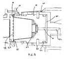
- Figures 7 to 9show another possible embodiment in which the injection cage 40 is formed of a piston unit 41 which is guided axially in a base 42, the said piston unit 41 completely forming the internal cavity 43.
- the cartridge 3 for its partis identical to the system of the preceding embodiment.
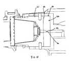
- the injection cage 40is mounted such that it can move in a structure 44 between an open position ( Figure 7 ) and a mechanically closed position ( Figure 8 ).
- the injection cageis thus held and guided in its movement by guide means 45 formed on the sides of the structure and complementing the cage guide means (for example, a rib/groove assembly) thus allowing it to move from one position to the other by actuation of a closure device 46.
- the closure deviceis of the latched lock lever type, for example, and is actuated by a lever or motor (not illustrated).
- a cartridge support 47is provided, and the cartridge will rest against this once the injection cage 40 has been closed and the nip region 16 of the cartridge has been trapped.
- the cartridge support 47comprises a structure in relief 48 for opening the delivery face of the cartridge, and identical to the one in the previous embodiment.
- the moving piston unit 41has a solid nip surface 49 which exerts pressure on the cartridge seal 17.
- the piston unitcomprises radial grooves 50 which act as starter channels for the passage of fluid and the creation of a pressure chamber 56 between the piston unit and the base.
- the grooves 50extend from a central supply duct 51 formed in the piston unit.
- the central duct 51communicates with a master supply duct 52 formed in the base 42, and itself supplied by pressurized-fluid supply means situated further upstream (pump, water heater, etc.).
- a seal 53such as an O-ring seal, is also provided between the base and the piston unit to prevent any leaks to the outside.
- the piston unitcomprises an annular groove in which the O-ring seal is housed.
- stop meansbetween the base and the unit. These are, for example, pegs 54 running in slots 55 of the base. This makes it possible to prevent the piston unit becoming detached from the base.
- the piston unit 41 of the injection cageis in the shape of a bell comprising a closed end in which means 62 piercing the injection face of the cartridge are formed.
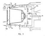
- FIGS 10 and 11illustrate another alternative form in which the pressure chamber is occupied by an incompressible elastic thrusting means 57.
- This meansoccupies the pressure chamber in the retracted position thereof (that is to say before pressurizing is performed).
- the incompressible elastic thrusting means 57comprises a first surface 58 on which the fluid pressure is exerted and which extends radially, and a second, thrust, surface 59 which extends transversely in order to exert thrust axially on the piston unit 41.
- the thrust surface 58delimits an expanding duct 70 which passes through the unit to allow fluid to pass to the internal cavity.
- the external surface of the unit on the opposite side to the surface 58is, for its part, blocked off by the internal surface of the piston unit. The unit therefore has a tendency to deform, thereby exerting axial thrust.
- An incompressible elastic thrusting meanssuch as this may be a block of deformable but relatively incompressible material. Since the block is made of a deformable material such as a silicone elastomer and occupies substantially the entire volume of the pressure chamber, it experiences a deforming thrust in a substantially radial direction of the duct 70 ( Figure 11 ) from a rest position ( Figure 10 ). The initial thrust surface on which the fluid pressure is exerted is substantially equal in size to the internal annular surface of the elastomer block. The thrust from the fluid is therefore substantially radial.
- the inventioncan be applied to any mechanical device for closing the extraction device in order to reduce the closure forces.
- the reduction in closure forcesmakes it possible to use a motor rather than a manually-operated closure device (such as a lever).
- the assistance afforded by the hydraulic means thus describedallows the force needed for mechanical closure to be reduced considerably.
- This applicationcan be envisaged for an extraction system that uses cartridges with or without seals. In the case of sealless cartridges, sealing has then to be provided by a seal formed on the injection cage.
Landscapes
- Engineering & Computer Science (AREA)
- Food Science & Technology (AREA)
- Mechanical Engineering (AREA)
- Apparatus For Making Beverages (AREA)
- Infusion, Injection, And Reservoir Apparatuses (AREA)
Abstract
Description
- The invention relates to the field of the preparation of beverages from a cartridge in an extraction device designed to accept such a cartridge; the device/cartridge assembly usually being termed the extraction "system".
- The technological background of the invention relates to the field of cartridges containing edible ingredients such as ground coffee and which are extracted under hot water pressure in an extraction device. The hot water is injected into the cartridge via an injection face using a piercing system, for example, the pressure of the fluid increases in the cartridge until another face of the cartridge is perforated or pierced by perforating means under the effect of the pressure so that the extract is delivered from the cartridge. A multitude of reliefs belonging to the perforating means allows controlled openings to be formed in the face of the cartridge while at the same time filtering the extract enough that the coffee grounds are kept inside the cartridge.
- A system such as this employing this method is known, for example, from patent
EP-A-512470 Patent application EP 1 654 966 proposes an improvement for providing better sealing upon closure of the extraction system so as to better control the extraction characteristics, particularly the opening and extraction pressures. To do that, the cartridge is equipped with an attached seal or a seal that forms an integral part of the cartridge so that each new cartridge extracted seals perfectly into the extraction system, thereby avoiding any risks of water leaking through the cartridge nip region to the outside. In the known systems, the seal is generally supported by the device, and this may present problems of wear and also of soiling that can then cause the extraction conditions to vary. Another advantage of the invention is that it allows the cartridge to be released more easily by preventing the cartridge from "sticking" in the cartridge cage through the effect of suction or vacuum. To do that, the invention may provide air passages such as grooves on the bearing surface of the cartridge cage.- In order to obtain a satisfactory seal, the seal supported by the cartridge needs to include a sufficient thickness of deformable material. This seal needs to be sized in such a way that it is compressed enough to fully compensate for any separation after closure and when the device is at its maximum pressure during extraction. Now, it has been found that the injection pressure, which may be as much as 12-20 bar, tends, at these high pressure levels, to cause the device to open up by the order of a few tenths of a millimetre at the cartridge nip region. The seal needs therefore to be able to compensate for such "dynamic" separation. If the seal is not tall enough, there is then insufficient compensation and leaks occur meaning that the increase in pressure in the cartridge cannot occur correctly.
- However, increasing the thickness of the seal in order to solve this problem of separation leads to additional cost in the production of the cartridge.
WO 2006/003116 relates to a percolating machine for producing a beverage using a sealed capsule of anhydrous powdered material. The capsule is a standard sealed capsule and the fluid tightness is obtained by a pressing seal of an hydraulically assisted sprinkler pressing against the flange of the capsule.- In particular, one of the objects of the invention is to retain the advantages of a seal associated with the cartridge while at the same time providing a solution to the problem of dynamic separation under the effect of the internal pressure during extraction.
- To do this, the invention relates to a extraction system for preparing a beverage according to
claim 1. - According to the invention, the cartridge seal forms a thickness of material that can be deformed under the effect of its being trapped in the device.
- As a preference, the seal is softer than the cartridge support with which the seal is in contact in the nip region of the cartridge and than the nip surface of the piston unit. For example, the support is typically a nipping edge of the cartridge. The nip surface of the piston unit may be made of a rigid material such as a metal or a plastic that cannot be deformed under the effect of the closure forces and the heat of the fluid.
- The seal is preferably of a thickness of 0.8 mm or less, and preferentially, of a thickness of between 0.2 and 0.6 mm. A thickness of this order of magnitude makes it possible to avoid the use of a seal in the device while at the same time offering dynamic sealing able to withstand high pressures, for example pressures ranging between 12 and 20 bar.
- The cartridge seal may be made of an elastically deformable material in order more readily to compensate for any possible opening-up at the nip surface of the cartridge cage. Examples of deformable materials for the seal may include elastomeric materials such as TPE (thermoplastic elastomer), LSR (liquid silicone rubber, silicone or EPDM.
- In some cases, the seal may also be made of a deformable, but slightly elastic, material, such as synthetic fibres, cellulose, foam, plastic or mastic.
- The seal may be an element that is prefabricated and assembled with the cartridge by any means of connection or alternatively may be co-manufactured with the cartridge. The seal may be an O-ring seal assembled with the cartridge. It may be fixed to the cartridge by bonding, welding or any other means of connection. It may also be deposited in liquid form and polymerized in situ or co-injected or over-injected according to the material of which the cartridge is made. The seal may also form an integral part of a wall of the cartridge and be formed of the same material, of plastic for example.
- As far as the extraction device is concerned, this comprises an injection cage comprising a base and a closure piston unit. The closure piston unit is able to move with respect to the base under the effect of the fluid upon injection.
- The injection cage in general comprises an internal extraction cavity of a shape designed to at least partially accept the contour of a cartridge, at least one fluid supply duct which supplies the cavity with fluid, possibly at least one opening means, such as a piercing element, allowing the cartridge to be opened so that the fluid can be introduced into the cartridge.
- The term "fluid" relates more specifically to hot water but the use of other liquids such as food liquids is not precluded.
- According to one feature, the piston unit is mounted with respect to the base so as to move coaxially therewith; the said unit defining, with the base, a pressure chamber the volume of which can expand; the expansion of the pressure chamber under the effect of the fluid having the effect of driving the said piston unit back towards the cartridge, and the said unit comprising a nip surface exerting closure forces against the cartridge seal in the cartridge nip region under the effect of the thrust exerted by the fluid on the piston unit.
- According to one feature of the invention, in order to provide a seal between the pressure chamber and the outside, at least one sealing means is provided between the piston unit and the base.
- According to another feature, an incompressible elastic thrusting means is provided in the pressure chamber and is elastically deformable and at least partially occupies the pressure chamber; this elastic means is arranged in the pressure chamber in such a way as to be deformed by the fluid and thus be able to apply axial thrusting forces against the action of the piston unit. According to one possible embodiment, the elastic means completely occupies the pressure chamber when the pressure chamber is in the position of rest. The object is to reduce the volume occupied by the fluid in the pressure chamber replacing the volume thereof with the elastic means. The elastic thrusting means absorbs the forces exerted by the pressurized fluid and transmits them to the piston unit. The advantages are better ability to control the closure forces (for example by providing materials of different hardnesses), of reducing fluid stagnation regions and preventing the pressure chamber from becoming soiled with food residue such as coffee grounds.
- The incompressible elastic thrusting means may thus be made of a silicone material or of some other elastomer. The hardness of such a material is adjusted to suit the desired performance and the desired closure forces to be transmitted.
- According to one possible embodiment, the incompressible elastic thrusting means comprises a first surface on which the fluid pressure is exerted, extending radially, and a second, thrust, surface extending transversely so as to exert axial thrust on the piston unit.
- According to one possible embodiment, the sealing means and the elastic means are one and the same element.
- The (projected) thrust surface of the piston unit, on which surface the pressure of the fluid outside the cartridge is exerted in order to perform closure is larger than the delivery surface of the cartridge. As a result, by providing a ratio of surface areas that is always in favour of the thrust surface, the separation forces tending to try to open up the device remain lower than the forces which close the device around the cartridge. As a preference, the thrust surface is about 1.2 to 2 times the size of the delivery surface.
- According to a first embodiment, the pressure chamber forms a continuation of the extraction cavity. The pressure chamber is then fed directly with fluid through at least one opening or a channel of the extraction cavity. The pressure chamber is preferably an annular continuation of the extraction cavity.
- In this case, the piston unit partially constitutes the extraction cavity so that the piston unit and the base together define the surfaces of the extraction cavity. In this case, the base comprises a fluid supply duct communicating directly with the extraction cavity. The base also preferably comprises at least one opening means, such as a piercing element for example projecting into the extraction cavity. The piston unit preferentially constitutes the lower (nip) part of the extraction cavity. It then comprises at least a substantially cylindrical or frustoconical part internally matching the external shape of the cartridge. In this case, the pressure chamber is preferably a substantially annular chamber positioned around the extraction cavity in order to extend it radially. A configuration such as this allows the bulk of the device to be reduced considerably.
- According to this same embodiment, the fluid is supplied to the pressure chamber by a plurality of openings or channels positioned radially between the extraction cavity and the annular pressure chamber. An arrangement such as this makes it possible to guarantee a uniform pressure increase in the chamber and therefore closure forces that are well distributed around the periphery of the nip surface. For example, the channels are of an open configuration and are arranged on one of the edges between the piston unit and the base so as to prevent them from possibly becoming blocked with scale or solid coffee particles. In this case, as the piston unit gradually moves away from the base, the openings or channels become larger and the chamber supply surface increases accordingly.
- According to a second possible embodiment, the pressure chamber extends upstream of the extraction cavity.
- In this case, the piston unit may entirely form the extraction cavity for accepting the cartridge so that the cavity of the piston unit is able to move relative to a base. In this case, the pressure chamber is supplied via at least one fluid channel situated in the base and upstream of the chamber. The extraction cavity is then itself supplied via the pressure chamber through at least one fluid channel formed through the piston unit.
- According to another advantage, means for detaching the cartridge provided, thereby avoiding a vacuum effect in the nip region. To do that, the nip surface of the piston unit preferably forms discontinuous nip portions for trapping the nip region of the cartridge.
- In particular, the nip surface of the piston unit comprises open grooves extending radially and separating the said discontinuous portions. The size of the grooves depends on the size of the cartridge seal. As a preference, the grooves are of a height that can be compensated by the thickness of the seal, which height is less than the thickness of the seal. As a preference, the height (H) of the grooves is equal to less than 2/3 of the thickness of the seal, preferably equal to about half the thickness of the seal. For example, the groove height is about 0.1 to 0.4 mm. The groove width is also preferably between about 0.8 and 3 mm.
- The extraction device is associated with a closure device for closing the injection cage and the extraction support around the cartridge before the pressure is increased. This closure may be considered as a "pre-closure" in as much as a certain closure force is already applied to the cartridge in the nip region by the device before the fluid pressurizes it. The closure device may be a mechanical, hydraulic or hydro mechanical device. It may also be a manually operated system or a system operated by a motor.
- The invention will be better understood and other features will become apparent from the detailed description of the attached drawings.
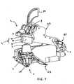
Figure 1 is a view in section and in perspective of the extraction system according to the invention, depicting the system in a first state of operation, in particular, in the opening mode with the insertion of a cartridge in the extraction device;Figure 2 is a perspective view of part of the system in its state according toFigure 1 ;Figure 3 is a view similar toFigure 2 but in a second operating state, particularly in the closure mode and before the system is pressurized;Figure 4 is a detailed sectional view of the system in the closure state according toFigure 3 ;Figure 5 is a view in section and in perspective of the extraction system in a third operating state, in particular, when the system is under pressure;Figure 6 is a detailed perspective view of the system under extraction pressure (without the cartridge membrane);Figure 7 is a side view in cross section of an extraction system according to a second embodiment depicting the invention in the mode of opening and inserting a cartridge into the extraction device;Figure 8 is a detailed sectional view of the system after mechanical closure but before the system is pressurized;Figure 9 is a detailed sectional view of the system as the system is pressurized;Figure 10 is a detailed sectional view of a third embodiment after mechanical closure but before the system is pressurized;Figure 11 is a detailed sectional view according to the embodiment ofFigure 10 , once the system has been pressurized.- With reference to
Figures 1 and2 , theextraction system 1 according to the invention, as depicted by way of nonlimiting example, is made up of anextraction device 2 in which there is housed acartridge 3 containing a food ingredient for preparing a beverage. Preparation is typically obtained by injecting a pressurized fluid into the cartridge and extracting the ingredient under the pressure of this fluid. The cartridge is a disposable cartridge and the spent cartridge is therefore generally thrown away or recycled. A new cartridge is then inserted into the device. - The "device-cartridge" assembly is known as the "extraction system" in the context of the present application. As will become obvious in what follows of the description, the device and the cartridge constitute means which cannot operate without one another and which interact physically and to complement one another in order to extract the liquid extract that is intended to form the beverage.
- The extraction device as such is an assembly comprising an injection cage 4 and a
cartridge support 5. The injection cage and the cartridge support are able to move relative to one another to close up around thecartridge 3. In this instance, the injection cage 4 is mounted on a mobileupper structure 6A, while thecartridge support 5 is mounted on a fixedlower structure 6B; the upper structure moving closer to the lower structure through a pivoting movement about an axis ofarticulation 7. The opposite could be anticipated, that is to say a cartridge cage that was fixed and a cartridge support that was able to move or alternatively, it could be anticipated for the two parts to move one towards the other. The dynamics governing the closing-up of the injection cage and the cartridge support is subject to numerous possible variants. Indeed, dynamics in which the parts move closer together in a linear path (rather than in a non-linear curve) is one possible variant. - The injection cage means the part containing means for injecting a pressurized fluid into the cartridge. These means usually comprise at least one main
fluid supply duct 8 and means of opening the cartridge. The opening means may, for example, be piercing elements 9 whose function is to create one or more openings in the cartridge in order to allow the fluid in. The piercing means may be separate from theduct 8, as illustrated. They may, for example, be elements in the form of blades, needles or spikes. In one variant, the duct may continue through the piercing element as such. Other opening means may be anticipated, according to the nature of the cartridge. - The injection cage has an
internal cavity 10 which accepts the injection face of the cartridge upon closure. Theinternal cavity 10 may vary in depth according to the shape of the cartridge. The free end of the cage has a nip surface 11. The injection cage is connected to a system for supplying the device with fluid which, inFigure 1 , is depicted only in part for purposes of simplicity. The fluid supply system generally comprises a water tank, a pressure pump and ducts for transporting the fluid, a water heater, such as a thermobloc, for example, to convey the fluid at the desired temperature for extraction. The pump may be an electromagnetic piston pump capable of developing a static pressure of several bar or any other type of equivalent pump. - The
cartridge support 5 has an extraction surface 60 allowing the cartridge to be perforated under the effect of the increase in pressure in the cartridge. To do that, the surface has at least one relief, preferably a series ofreliefs 12, forming means of perforating the cartridge. The reliefs may differ in geometry according to the type of cartridge and the desired extraction conditions. In the example, each relief in the shape of a truncated pyramid. A network ofchannels 61 is formed through which the liquid extract can flow between the structure of reliefs so that liquid can be collected in a container (cup or the like). - As shown in
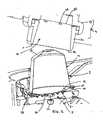
Figure 2 , thecartridge 3 according to the system of the invention has aninjection wall 13 which may be closed at the time the cartridge is inserted into or deposited in the device. The injection wall may be formed in a dished body 14 (for example in the shape of (a) cone frustum(s)). The cartridge has adelivery wall 15 through which the extract needs to be able to flow once openings have been made by the perforating means 12 of the extraction surface of the support. Awall 15 such as this may be a membrane made of aluminium, plastic or plastic/aluminium laminate and which can be perforated. For example, the wall is an aluminium foil a few tenths of a micron thick which tears when it reaches its rupture stress upon contact with thereliefs 12 at a pressure that may range between 6 and 20 bar depending on the cartridge, the ingredients and the thickness of the membrane. The body of the cartridge may be made of a rigid or semirigid material such as aluminium, plastic or a plastic-aluminium laminate. - The cartridge comprises a
nip region 16 via which it is trapped when the device is closed onto the cartridge. Trapping is achieved by bringing the injection cage 4 and theextraction support 5 closer together and then clamping them on either side of the said nipregion 16. Thenip region 16 is formed of a border running radially around the periphery of the cartridge. The border may, at least in part, be formed of the body of the cartridge. Themembrane 15 may be assembled with the underside of the border in thenip region 16 by sealing or welding. According to the invention, the nip region comprises a sealing means in the form of aseal 17 which occupies all or some of the border. Theseal 17 is preferably an element made of a deformable material that is relatively soft and attached or fixed against the rim. A relatively soft material is to be understood as meaning a material capable of deforming in order to thereby compensate at least for any opening up of the injection cage at the nip surface as will be explained hereinafter. As a preference, the seal is made of an elastic material such as an elastomer. The thickness of the seal is preferably 0.8 mm or less. - The shape of the seal may be designed in such a way as to encourage it to creep as the pressure rises, so as to provide a better seal uses a minimum amount of material. In the example illustrated, the seal has a greater thickness on the rim facing towards the wall of the
body 14 of the cartridge than it does towards the free end of the rim thus allowing the material to move outwards under the effect of the pressure of the fluid thrusting against the cavity and the wall of the cartridge. The thickness of the seal on the side wall side may be about 0.5 mm and decrease towards the outside to a value ranging between 0 and 0.2 mm. The rim of the cartridge may end in a crimpedseam 18 as is known per se, and to which the trapping forces are not, in theory, applied. - According to the invention, the injection cage is designed to be pressurized in such a way as to increase the closure forces against the nip region after the device has been mechanically closed. To do that, the injection cage comprises a
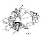
base 19 and apiston unit 20 which is mounted axially with respect to the base with the ability of controlled movement. AsFigures 3 and4 show, the piston unit comprises alateral rim 21 which fits into agroove 22 formed in thebase 19. The rim/groove assembly defines apressure chamber 23 the volume of which can expand. The chamber may be partially occupied by a sealing means 24 such as an elastic block that seals the chamber against the outside at the rim/groove interface. The fluid is conveyed into the chamber from the internal extraction cavity by starter channels orchannels 25. These may, for example, be formed on theline 26 where the piston unit and the base that forms the top of the cavity meet. In the example illustrated, we have starter channels forming notches widening towards the cavity and positioned on the upper rim of thepiston unit 20. They could also be formed at least partially on the lower rim of the base. The channels orstarter channels 25 are radially arranged and distributed uniformly about the periphery of the cavity so as to balance the pressurizing of the chamber and allow the piston unit to move as linearly as possible along the base. - The device also comprises means 27 for collecting and delivering the liquid extract, these being positioned downstream of the extraction support (
Figures 1 and5 ). These means, known per se, for example comprise a funnel-shaped collector and possibly a jet-regulating element. - The device is equipped with a
mechanical closure device 28 as known per se. A device such as this need not be described in detail in this application. It may be based on a mechanism for transmitting a force from amanual lever 29 or motor (not illustrated) to the structure supporting the injection cage. A mechanism such as this may be a mechanism employing the principle of a latch lock lever such as, by way of example, the one described in Patent ApplicationsEP 1090574 or alternativelyEP 1495702 . It may also be a cam mechanism, a mechanism involving an electromagnetic field (solenoid) and/or a hydraulic mechanism. Figures 3 and4 show the extraction system after the device has been closed around the cartridge using theclosure device 28. Thelever 29 is actuated to bring the injection cage 4 closer to the extraction support to the point that thenip region 16 of the cartridge is firmly trapped. In this operating state, the cavity moves towards the cartridge, thus forcing the piercing elements 9 through the injection wall of thecartridge 3. As shown byFigure 4 , the piston unit is extended towards itsfree end 30 by a nip surface 11 which applies clamping forces to the cartridge seal as a result of the mechanical closure. It may be noted that the seal is already preloaded and is compressed to a certain degree. The extraction support serves to produce opposing forces to trap the rim and immobilize the cartridge in the said region.- As a preference, the nip surface 11 has discontinuous nip portions which between them delimit grooves 31 (
Figure 1 ) running in the radial direction with respect to the axial line I of the surface of revolution formed by the extraction cavity. The number ofgrooves 31 may vary but, as a preference, is greater than 10, even greater than 20. The grooves are preferably distributed about the entire periphery of the nip surface. - As a preference also, the end of the piston unit ends in a nip surface with internal 32 and external 33 edges converging towards one another to form a relatively narrow and localized surface 11. The width of the nip surface 11 is preferably equal to 1 mm or less. Likewise, the nip surface preferably exerts forces closer to the lateral wall of the body of the cartridge than to the free edge of the border. The narrow width of the nip surface means that locally higher forces can be applied and also makes it possible to minimize the thickness and/or the width of the seal while at the same time ensuring a good seal. As a preference, the
internal edge 32 makes an angle A smaller than the angle B of the external edge 33 (A and B being referenced with respect to the axis I). The angle A preferably ranges between 5 and 10 degrees while the angle B ranges between 30 and 60 degrees. - In the operating state of
Figures 3 and4 , no fluid has yet been injected through the duct and the piston unit is in the retracted position. Thepressure chamber 23 has not yet been subjected to the pressure of the fluid. Figures 5 and6 show the extraction step proper. An injection fluid is sent through thesupply duct 8 by the pump of the device until the pressure in thecartridge 3 and the internal cavity increase. The pressurized fluid fills the cavity, the cartridge and the pressure chamber through the starter ducts and along themeeting line 26 as the piston unit moves to close up against the seal and the rim of the cartridge. The pressure chamber expands under the effect of the pressurizing of the fluid in the cavity and in the cartridge. The projected axial surface at the pressure chamber is appreciably larger than the delivery surface of the cartridge which means that the clamping forces exerted on the nip surface by the piston unit always remain higher than the separating forces exerted at the nip region but on the internal cavity side (between the wall of the cartridge and the cavity). Thus, the seal created is maintained throughout the extraction process.- During the extraction process, thanks to the fact that sealing is maintained, the pressure exerted on the membrane against the reliefs reaches a value (ranging between about 6 and 20 bar according to the cartridge) such that it leads to the tearing of the membrane against the reliefs reaching the rupture stress of the material of the membrane. The membrane therefore tears in a controller and localized way to form openings at the corners of the reliefs. In some cases, the pressure in the cartridge may continue to increase appreciably because of any possible compaction of the bed of coffee in the cartridge. The extraction is filtered by the membrane and by the reliefs. The extract is collected in the channels of the extraction support as far as holes (not featured) made through and/or on the sides of the support.
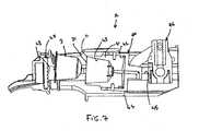
Figures 7 to 9 show another possible embodiment in which the injection cage 40 is formed of apiston unit 41 which is guided axially in abase 42, the saidpiston unit 41 completely forming theinternal cavity 43. Thecartridge 3 for its part is identical to the system of the preceding embodiment.- The injection cage 40 is mounted such that it can move in a structure 44 between an open position (
Figure 7 ) and a mechanically closed position (Figure 8 ). The injection cage is thus held and guided in its movement by guide means 45 formed on the sides of the structure and complementing the cage guide means (for example, a rib/groove assembly) thus allowing it to move from one position to the other by actuation of aclosure device 46. The closure device is of the latched lock lever type, for example, and is actuated by a lever or motor (not illustrated). Acartridge support 47 is provided, and the cartridge will rest against this once the injection cage 40 has been closed and thenip region 16 of the cartridge has been trapped. - The
cartridge support 47 comprises a structure inrelief 48 for opening the delivery face of the cartridge, and identical to the one in the previous embodiment. - As before, the moving
piston unit 41 has asolid nip surface 49 which exerts pressure on thecartridge seal 17. - As shown by
Figure 8 , the piston unit comprisesradial grooves 50 which act as starter channels for the passage of fluid and the creation of apressure chamber 56 between the piston unit and the base. Thegrooves 50 extend from acentral supply duct 51 formed in the piston unit. Thecentral duct 51 communicates with amaster supply duct 52 formed in thebase 42, and itself supplied by pressurized-fluid supply means situated further upstream (pump, water heater, etc.). - A
seal 53, such as an O-ring seal, is also provided between the base and the piston unit to prevent any leaks to the outside. For that, the piston unit comprises an annular groove in which the O-ring seal is housed. Likewise, the travel of the piston unit is controlled by stop means between the base and the unit. These are, for example, pegs 54 running inslots 55 of the base. This makes it possible to prevent the piston unit becoming detached from the base. - The
piston unit 41 of the injection cage is in the shape of a bell comprising a closed end in which means 62 piercing the injection face of the cartridge are formed. - In the operating state of
Figure 8 , the injection cage is closed up against the cartridge and the extraction support by the closure means 46. Only mechanical pressure of thenip surface 49 of the piston unit is exerted on thecartridge seal 17. - In the operating state of
Figure 9 , the system is pressurized with fluid and the piston unit is driven back, exerting additional clamping forces on thecartridge seal 17. Figures 10 and11 illustrate another alternative form in which the pressure chamber is occupied by an incompressible elastic thrustingmeans 57. This means occupies the pressure chamber in the retracted position thereof (that is to say before pressurizing is performed). The incompressible elastic thrustingmeans 57 comprises afirst surface 58 on which the fluid pressure is exerted and which extends radially, and a second, thrust, surface 59 which extends transversely in order to exert thrust axially on thepiston unit 41. Thethrust surface 58 delimits an expanding duct 70 which passes through the unit to allow fluid to pass to the internal cavity. The external surface of the unit on the opposite side to thesurface 58 is, for its part, blocked off by the internal surface of the piston unit. The unit therefore has a tendency to deform, thereby exerting axial thrust.- An incompressible elastic thrusting means such as this may be a block of deformable but relatively incompressible material. Since the block is made of a deformable material such as a silicone elastomer and occupies substantially the entire volume of the pressure chamber, it experiences a deforming thrust in a substantially radial direction of the duct 70 (
Figure 11 ) from a rest position (Figure 10 ). The initial thrust surface on which the fluid pressure is exerted is substantially equal in size to the internal annular surface of the elastomer block. The thrust from the fluid is therefore substantially radial. Since a block such as this is incompressible, its external surface is compressed against the internal surface and the end surface of the piston unit in such a way that an axial thrust is absorbed perpendicular to the radial thrust of the fluid and therefore exerted on the piston unit in the direction of thenip region 16. Thepiston unit 41 therefore moves towards the nip region, exerting forces that cause it to close against theseal 17. - In general, the invention can be applied to any mechanical device for closing the extraction device in order to reduce the closure forces. For example, the reduction in closure forces makes it possible to use a motor rather than a manually-operated closure device (such as a lever). The assistance afforded by the hydraulic means thus described allows the force needed for mechanical closure to be reduced considerably. This application can be envisaged for an extraction system that uses cartridges with or without seals. In the case of sealless cartridges, sealing has then to be provided by a seal formed on the injection cage.
Claims (24)
- Extraction system (1) for preparing a beverage from a cartridge using a fluid injected under pressure into the said cartridge and comprising:- a cartridge (3) comprising:a beverage delivery wall (15) which can be perforated under the effect of the pressure of the fluid within the cartridge,a wall (13) for injecting the fluid into the cartridge,a nip region (16) formed of a border running radially around the periphery of the cartridge,- an extraction device (2) intended to accept the said cartridge and comprising:an injection cage (4, 40) comprising fluid injection means (8, 9, 51, 52, 62, 70), anda cartridge support (5, 48) comprising perforating means (12, 60) for perforating the delivery wall (15) of the cartridge under the effect of the pressure of the fluid in the cartridge;the said injection cage (4, 40) and the said cartridge support (5, 48) being arranged in such a way as to be moved relative to one another by a closure device (28, 46) which closes them around the cartridge prior to injection, and to trap the cartridge in the said nip region,
wherein the injection cage (4, 40) comprises a base (19, 42) and a closure piston unit (20, 41) which is mounted so that it can move axially with respect to the said base;
the said closure piston unit (20, 41) can move relative to the base (19, 42) under the effect of the pressure of the fluid against the nip region of the cartridge (16) in order to generate clamping forces that prevent the injection cage and the cartridge support from opening up relative to one another as the system is pressurizedcharacterized in that the cartridge comprises a sealing means (17), made of deformable material, belonging to the cartridge or attached to the latter and to which the clamping forces of the piston unit (20, 41) are applied and which is in the form of a seal occupying all or some of the border. - Extraction system according to claim 1,characterized in that the seal occupies some of the border.
- Extraction system according to claims 1 or 2,characterized in that the delivery wall (15) is a membrane assembled with the underside of the border in the nip region by sealing or welding.
- Extraction system according to any one of claims 1 to 3,characterized in that the sealing means (17) is a seal forming a thickness of material that is deformed under the effect of its being trapped in the device.
- Extraction system according to claim 4,characterized in that the seal is softer than the cartridge support which the seal is in contact in the nip region and the nip surface of the piston unit.
- Extraction system according to Claims 4 or 5,characterized in that the cartridge sealing means (17) is a seal of a thickness of 0.8 mm or less.
- Extraction system according to Claim 6,characterized in that the cartridge sealing means (17) is a seal of a thickness ranging between about 0.2 and 0.6 mm.
- Extraction system according to any of claims 1 to 7,characterized in that the sealing means is made of an elastically deformable material in order to more readily compensate for any possible opening-up at the nip surface of the cartridge cage, in particular, an elastomeric material such as TPE (thermoplastic elastomer), LSR (liquid silicone rubber), silicone or EPDM.
- Extraction system according to any of claims 1 to 7,characterized in that the sealing means is made of a deformable, but slightly elastic material, such as synthetic fibres, cellulose, foam, plastic or mastic.
- Extraction system according to any of claims 1 to 7,characterized in that the seal is formed of an integral part of the wall of the cartridge and is formed of same material such as plastic.
- Extraction system according to any one of the preceding claims,characterized in that the piston unit comprises a nip surface (11) of a width of 1 mm or less.
- Extraction system according to any one of the preceding claims,characterized in that the injection cage (4, 48) comprises an internal extraction cavity (10, 43) of a shape designed to at least partially accept the cartridge.
- Extraction system according to Claim 12,characterized in that the cavity (10, 43) comprises at least one fluid supply duct (8, 51) and possibly at least one opening element (9, 62).
- Extraction system according to Claims 12 or 13,characterized in that the injection cage comprises a pressure chamber (23, 56).
- Extraction system according to Claim 14,characterized in that the pressure chamber (23, 56) is at least partially occupied by an elastic thrusting means.
- Extraction system according to Claim 15,characterized in that the pressure chamber (23, 56) at rest is entirely occupied by an elastic thrusting means (57).
- Extraction system according to Claims 14, 15 or 16,characterized in that the pressure chamber (23) forms an extension of the extraction cavity (10).
- Extraction system according to Claim 17,characterized in that the pressure chamber (23) forms an annular extension of the extraction cavity (10).
- Extraction system according to Claim 17 or 18,characterized in that the pressure chamber (23) communicates with the extraction cavity (10) via at least one opening or channel or starter channel (25).
- Extraction system according to Claim 19,characterized in that the fluid is supplied to the pressure chamber by a plurality of openings or channels or starter channels (25) positioned radially between the extraction cavity (10) and the pressure chamber (23).
- Extraction system according to Claims 14, 15 or 16,characterized in that the pressure chamber (56, 58) extends upstream of the extraction cavity (43).
- Extraction system according to one of the preceding claims,characterized in that the nip surface (11) of the piston unit forms discontinuous pressure surface portions for pressing against the nip region of the cartridge.
- Extraction system according to Claim 22,characterized in that the piston unit comprises a nip surface (11) comprising open grooves (31) extending radially and separating the said discontinuous nip portions.
- Use of the cartridge (3) in the extraction system (1) according to any of the preceding claims 1 to 23 for preparing a beverage.
Priority Applications (3)
| Application Number | Priority Date | Filing Date | Title |
|---|---|---|---|
| EP10182957.0AEP2305080B1 (en) | 2006-09-26 | 2007-09-20 | Extraction system for the preparation of beverage from a cartridge |
| EP07820374AEP2068684B1 (en) | 2006-09-26 | 2007-09-20 | Extraction system for the preparation of a beverage from a cartridge |
| PL07820374TPL2068684T3 (en) | 2006-09-26 | 2007-09-20 | Extraction system for the preparation of a beverage from a cartridge |
Applications Claiming Priority (3)
| Application Number | Priority Date | Filing Date | Title |
|---|---|---|---|
| EP06121239 | 2006-09-26 | ||
| PCT/EP2007/059930WO2008037642A2 (en) | 2006-09-26 | 2007-09-20 | Extraction system for the preparation of a beverage from a cartridge |
| EP07820374AEP2068684B1 (en) | 2006-09-26 | 2007-09-20 | Extraction system for the preparation of a beverage from a cartridge |
Related Child Applications (2)
| Application Number | Title | Priority Date | Filing Date |
|---|---|---|---|
| EP10182957.0ADivisionEP2305080B1 (en) | 2006-09-26 | 2007-09-20 | Extraction system for the preparation of beverage from a cartridge |
| EP10182957.0Division-Into | 2010-09-30 |
Publications (2)
| Publication Number | Publication Date |
|---|---|
| EP2068684A2 EP2068684A2 (en) | 2009-06-17 |
| EP2068684B1true EP2068684B1 (en) | 2011-02-16 |
Family
ID=37945029
Family Applications (2)
| Application Number | Title | Priority Date | Filing Date |
|---|---|---|---|
| EP07820374AActiveEP2068684B1 (en) | 2006-09-26 | 2007-09-20 | Extraction system for the preparation of a beverage from a cartridge |
| EP10182957.0AActiveEP2305080B1 (en) | 2006-09-26 | 2007-09-20 | Extraction system for the preparation of beverage from a cartridge |
Family Applications After (1)
| Application Number | Title | Priority Date | Filing Date |
|---|---|---|---|
| EP10182957.0AActiveEP2305080B1 (en) | 2006-09-26 | 2007-09-20 | Extraction system for the preparation of beverage from a cartridge |
Country Status (23)
| Country | Link |
|---|---|
| US (1) | US8844428B2 (en) |
| EP (2) | EP2068684B1 (en) |
| JP (1) | JP5185276B2 (en) |
| KR (1) | KR20090058034A (en) |
| CN (1) | CN101528094B (en) |
| AR (1) | AR063948A1 (en) |
| AT (1) | ATE498341T1 (en) |
| AU (2) | AU2007302077A1 (en) |
| BR (1) | BRPI0717258B1 (en) |
| CA (1) | CA2663945C (en) |
| CL (1) | CL2007002772A1 (en) |
| DE (2) | DE202007019239U1 (en) |
| ES (1) | ES2356791T3 (en) |
| IL (1) | IL197630A (en) |
| MX (1) | MX2009003105A (en) |
| MY (1) | MY152872A (en) |
| NO (1) | NO20091431L (en) |
| PL (1) | PL2068684T3 (en) |
| PT (1) | PT2068684E (en) |
| RU (1) | RU2414160C2 (en) |
| TW (1) | TW200838466A (en) |
| WO (1) | WO2008037642A2 (en) |
| ZA (1) | ZA200902868B (en) |
Cited By (13)
| Publication number | Priority date | Publication date | Assignee | Title |
|---|---|---|---|---|
| US10835074B2 (en) | 2015-05-15 | 2020-11-17 | Koninklijke Douwe Egberts B.V. | Capsule, a system for preparing a potable beverage from such a capsule and use of such a capsule in a beverage preparation device |
| US10940995B2 (en) | 2015-05-15 | 2021-03-09 | Koninklijke Douwe Egberts B.V. | Capsule, a system for preparing a potable beverage from such a capsule and use of such a capsule in a beverage preparation device |
| US11198557B2 (en) | 2016-10-07 | 2021-12-14 | Koninklijke Douwe Egberts B.V. | Capsule, a system for preparing a potable beverage |
| US11198556B2 (en) | 2015-05-15 | 2021-12-14 | Koninklijke Douwe Egberts B.V. | Capsule, a system for preparing a potable beverage from such a capsule and use of such a capsule in a beverage preparation device |
| US11311137B2 (en) | 2014-01-03 | 2022-04-26 | Koninklijke Douwe Egberts B.V. | Exchangeable supply pack for a beverage dispensing machine, doser, pump assembly and method of manufacturing |
| US11352199B2 (en) | 2015-05-15 | 2022-06-07 | Koninklijke Douwe Egberts B.V. | Capsule, a system for preparing a potable beverage from such a capsule and use of such a capsule in a beverage preparation device |
| US11673738B2 (en) | 2016-05-13 | 2023-06-13 | Koninklijke Douwe Egberts B.V. | Capsule, a system for preparing a potable beverage from such a capsule and use of such a capsule in a beverage preparation device |
| US11679929B2 (en) | 2016-05-13 | 2023-06-20 | Koninklijke Douwe Egberts B.V. | Capsule and a system for preparing a potable beverage from such a capsule |
| US11760561B2 (en) | 2015-05-15 | 2023-09-19 | Koninklijke Douwe Egberts B.V. | Capsule, a system for preparing a potable beverage from such a capsule and use of such a capsule in a beverage preparation device |
| US11772883B2 (en) | 2015-05-15 | 2023-10-03 | Koninklijke Douwe Egberts B.V. | Capsule, a system for preparing a potable beverage from such a capsule and use of such a capsule in a beverage preparation device |
| US11827446B2 (en) | 2015-10-27 | 2023-11-28 | Koninklijke Douwe Egberts B.V. | Capsule, system and method for preparing a beverage |
| US11844453B2 (en) | 2017-07-14 | 2023-12-19 | Koninklijke Douwe Egberts N.V. | Capsule for the preparation of a beverage |
| US12214955B2 (en) | 2016-10-07 | 2025-02-04 | Koninklijke Douwe Egberts B.V. | Capsule, system and method for preparing a beverage |
Families Citing this family (85)
| Publication number | Priority date | Publication date | Assignee | Title |
|---|---|---|---|---|
| EP1495702A1 (en) | 2003-07-10 | 2005-01-12 | Nestec S.A. | Device for the extraction of a cartridge |
| AU2007302077A1 (en) | 2006-09-26 | 2008-04-03 | Nestec S.A. | Extraction system for the preparation of a beverage from a cartridge |
| US8114828B2 (en)* | 2007-04-16 | 2012-02-14 | Honeywell International Inc. | Azeotrope-like compositions of tetrafluoropropene and alcohols |
| CN102133047B (en) | 2007-10-04 | 2014-04-30 | 雀巢产品技术援助有限公司 | Heating device with an integrated thermoblock for a beverage preparation machine |
| EP2218369B1 (en) | 2007-10-04 | 2017-05-03 | Nestec S.A. | Beverage brewing unit |
| CL2008002963A1 (en) | 2007-10-04 | 2010-01-22 | Nestec Sa | Heating device for a machine for the preparation of liquid food or drink, comprising a thermal unit with a metallic mass, through which the liquid circulates, and accumulates heat and supplies it to the liquid, and has one or more insured electrical components rigidly to the thermal unit; and machine. |
| PT2142054E (en)† | 2008-03-20 | 2011-01-24 | Nestec Sa | Beverage production device for producing a beverage from a single-use capsule |
| JP2011518015A (en) | 2008-04-22 | 2011-06-23 | ネステク ソシエテ アノニム | Module assembly for beverage production equipment |
| EP2309900B1 (en) | 2008-08-08 | 2015-05-27 | Nestec S.A. | Beverage machine with carrying handle and configurable appearance&side functions |
| MX2011005991A (en)* | 2008-12-03 | 2011-06-27 | Nestec Sa | Capsule for the preparation of a beverage by centrifugation. |
| PT2966007T (en) | 2009-06-17 | 2017-12-20 | Douwe Egberts Bv | Capsule, system and method for preparing a predetermined quantity of beverage suitable for consumption |
| PT2312978E (en) | 2009-07-23 | 2013-11-11 | Ethical Coffee Company Sa | Device for preparing a drink extracted from a capsule |
| PT2284101E (en) | 2009-08-05 | 2011-11-30 | Nestec Sa | Capsule with relief-shaped sealing member |
| US8973488B2 (en) | 2009-10-05 | 2015-03-10 | Nestec S.A. | Cartridge extraction device |
| IT1396016B1 (en)* | 2009-10-15 | 2012-11-09 | Swiss Caffe Asia Ltd | INFUSION DEVICE FOR INFUSION AND SIMILAR CAPSULES, PARTICULARLY FOR ESPRESSO AND SIMILAR COFFEE MACHINES. |
| GB2475291B (en)* | 2009-11-12 | 2012-03-28 | Kraft Foods R & D Inc | Beverage preparation machines |
| AU2010321054B2 (en) | 2009-11-19 | 2015-07-09 | Société des Produits Nestlé S.A. | Capsule and method for preparing a beverage such as coffee from said capsule |
| CN102639037B (en) | 2009-12-01 | 2015-11-25 | 雀巢产品技术援助有限公司 | Cartridge extraction device |
| EP2353469A1 (en) | 2010-02-03 | 2011-08-10 | Nestec S.A. | Beverage preparation machine for large size beverages |
| ES2711833T3 (en)* | 2010-03-19 | 2019-05-07 | Nestec Sa | A beverage machine which uses ingredient capsules |
| PT2374383E (en) | 2010-04-07 | 2012-12-10 | Nestec Sa | Extraction system for the production of a beverage using a capsule |
| EP2608704B1 (en) | 2010-08-27 | 2016-06-22 | Nestec S.A. | Simple motorized brewing unit |
| JP5796852B2 (en)* | 2010-10-08 | 2015-10-21 | キュー・ビー・オー・コーヒー・ゲゼルシャフト・ミット・ベシュレンクテル・ハフツングQbo Coffee Gmbh | Extraction device and sealing system |
| US20120097602A1 (en)* | 2010-10-22 | 2012-04-26 | International Paper Company | Biodegradable or compostable beverage filter cartridge |
| CN103313634B (en)* | 2010-12-28 | 2016-10-26 | 星巴克公司,贸易用名星巴克咖啡公司 | Apparatus and related method for brewing beverages |
| BR112014003976A2 (en) | 2011-08-25 | 2017-03-07 | Nestec Sa | cartridge chamber of an extraction system |
| JP6223339B2 (en) | 2011-08-25 | 2017-11-01 | ネステク ソシエテ アノニム | Cartridge alignment system |
| BR112014003791A2 (en) | 2011-08-25 | 2017-03-14 | Nestec Sa | cartridge removal system |
| RU2014111180A (en) | 2011-08-25 | 2015-09-27 | Нестек С.А. | CARTRIDGE PUNCH PUNCH WITH LONG SERVICE LIFE |
| ITMI20120247A1 (en) | 2012-02-20 | 2013-08-21 | Illycaffe Spa | CARTRIDGE FOR OBTAINING A DRINK. |
| DE112012001531T5 (en) | 2012-02-28 | 2013-12-24 | Nestec S.A. | Capsule-controlled motorized brewing unit |
| CN102670076B (en)* | 2012-05-10 | 2014-02-19 | 宁波全景电器技术有限公司 | Automatic bag drop mechanism of beverage preparation device |
| GB2503283B (en)* | 2012-06-22 | 2020-04-15 | Alex Gort Barten | Coffee machine |
| CN104869874B (en) | 2012-10-09 | 2018-01-05 | 雀巢产品技术援助有限公司 | Extraction unit with more size magazine chambers |
| RU2015116419A (en) | 2012-10-09 | 2016-11-27 | Нестек С.А. | EXTRACTION DEVICE WITH ADJUSTABLE RECEIVER FOR VARIOUS SIZES CAPSULES |
| ES2987856T3 (en) | 2012-12-19 | 2024-11-18 | Nestle Sa | Method of extracting cartridges in an extraction unit |
| WO2015086371A1 (en) | 2013-12-11 | 2015-06-18 | Nestec S.A. | Beverage machine with a pivotable capsule gate |
| WO2015155145A1 (en) | 2014-04-08 | 2015-10-15 | Nestec S.A. | Multisize capsule handling with serial actuation |
| BR112017006875A2 (en) | 2014-10-08 | 2017-12-12 | Nestec Sa | reconfigurable beverage preparation machine |
| RU2017115547A (en) | 2014-10-08 | 2018-11-12 | Нестек С.А. | EXTRACTION UNIT FOR DRINKS |
| CA3207639A1 (en) | 2014-10-20 | 2016-04-28 | Bedford Systems Llc | Cartridge holder for beverage machine |
| EP3223667A1 (en) | 2014-11-27 | 2017-10-04 | Nestec S.A. | Ergonomic handle arrangement |
| GB2539929B (en)* | 2015-07-01 | 2018-06-27 | Alex Gort Barten | Coffee Capsule |
| ES2784373T3 (en)* | 2015-12-22 | 2020-09-24 | Koninklijke Philips Nv | Brewing unit for a beverage production machine and a machine containing the brewing unit |
| PT3509464T (en) | 2016-09-09 | 2021-10-13 | Nestle Sa | BEVERAGE MACHINE WITH ERGONOMIC HANDLING |
| CA3041722A1 (en) | 2016-11-09 | 2018-05-17 | Pepsico, Inc. | Carbonated beverage makers, methods, and systems |
| US11432674B2 (en) | 2017-02-28 | 2022-09-06 | Societe Des Produits Nestle S.A. | Dispenser with parallel dispensing paths |
| WO2018219989A1 (en) | 2017-06-01 | 2018-12-06 | Nestec Sa | Beverage machine with a stablizing foot |
| CN110662469B (en) | 2017-06-01 | 2023-03-14 | 雀巢产品有限公司 | Beverage machine with storable dispensing head |
| WO2018219984A1 (en) | 2017-06-01 | 2018-12-06 | Nestec Sa | Beverage machine with a collapsible interface |
| CN110662468B (en) | 2017-06-01 | 2022-04-29 | 雀巢产品有限公司 | Beverage machine with ergonomic power switch |
| CN110753505B (en) | 2017-06-13 | 2022-03-15 | 雀巢产品有限公司 | Beverage preparation machine with capsule recognition |
| WO2019057619A1 (en) | 2017-09-25 | 2019-03-28 | Nestec Sa | Beverage machines with modularity |
| CN111132588A (en) | 2017-09-25 | 2020-05-08 | 雀巢产品有限公司 | Beverage machine with removable module |
| CN111954480B (en)* | 2017-10-19 | 2022-06-14 | 意大利Sgl有限责任公司(独资) | Brewing device for producing a beverage |
| GB201720894D0 (en)* | 2017-11-08 | 2018-01-31 | Gort-Barten Alex | Beverage capsule |
| EP3501345B1 (en)* | 2017-12-22 | 2021-04-14 | Société des Produits Nestlé S.A. | Exchangeable cartridge for beverage portion dispenser |
| EP3727102A1 (en)* | 2017-12-22 | 2020-10-28 | Société des Produits Nestlé S.A. | Multi-serve airtight coffee dispenser |
| CN108143283B (en)* | 2018-02-09 | 2023-11-17 | 珠海易咖科技有限公司 | Pressing device of coffee brewing box and coffee machine |
| JP7242686B2 (en) | 2018-02-09 | 2023-03-20 | ソシエテ・デ・プロデュイ・ネスレ・エス・アー | Beverage preparation machine that recognizes capsules |
| IT201800002546A1 (en)* | 2018-02-09 | 2019-08-09 | Capitani Srl | INFUSION DEVICE |
| JP2021515623A (en) | 2018-03-14 | 2021-06-24 | ソシエテ・デ・プロデュイ・ネスレ・エス・アー | Beverage machine with controlled outflow opening |
| BR112020015699A2 (en) | 2018-03-14 | 2020-12-08 | Société des Produits Nestlé S.A. | DRINKING MACHINE WITH A PARTIALLY CLOSED DISPENSING FACE |
| JP2021515626A (en) | 2018-03-14 | 2021-06-24 | ソシエテ・デ・プロデュイ・ネスレ・エス・アー | Beverage machine that controls and pierces capsules |
| EP3764850A1 (en) | 2018-03-14 | 2021-01-20 | Société des Produits Nestlé S.A. | Beverage machine with a non-homogeneous ingredient extraction configuration |
| US12390044B2 (en) | 2018-09-27 | 2025-08-19 | Societe Des Produits Nestle S.A. | Adaptive service unit of a beverage machine |
| EP3628195A1 (en) | 2018-09-27 | 2020-04-01 | Société des Produits Nestlé S.A. | Beverage preparation machine with recipient detection |
| PT3855986T (en) | 2018-09-27 | 2023-09-11 | Nestle Sa | Beverage machine with an actuation distribution |
| WO2020104667A1 (en)* | 2018-11-22 | 2020-05-28 | K-Fee System Gmbh | Seal for a single serve capsule |
| CA3121432A1 (en) | 2018-12-12 | 2020-06-18 | Societes Des Produits Nestle S.A. | Beverage preparation machine with capsule recognition |
| AU2019446901B2 (en) | 2019-05-20 | 2025-08-21 | Eugster / Frismag Ag | Brewing apparatus and method for operating a brewing apparatus |
| GB2616366B (en)* | 2019-09-18 | 2024-05-29 | Alex Gort Barten | Beverage capsule manufacture |
| ES2975752T3 (en) | 2020-02-05 | 2024-07-12 | Nestle Sa | Capsule recognition beverage preparation machine |
| CN115023164A (en) | 2020-02-05 | 2022-09-06 | 雀巢产品有限公司 | Beverage preparation machine with capsule recognition |
| CN116829474A (en)* | 2020-12-07 | 2023-09-29 | Gcs德国胶囊解决方案股份有限公司 | Single-serving capsule for preparing a beverage in a beverage preparation machine and method for producing a single-serving capsule |
| US20250255428A1 (en) | 2022-04-14 | 2025-08-14 | Societe Des Produits Nestle S.A. | Centrifugal chamber with capsule opening elements |
| JP2025511671A (en) | 2022-04-14 | 2025-04-16 | ソシエテ・デ・プロデュイ・ネスレ・エス・アー | Centrifugal beverage chamber with closure fastener - Patents.com |
| JP2025511669A (en) | 2022-04-14 | 2025-04-16 | ソシエテ・デ・プロデュイ・ネスレ・エス・アー | Centrifugal chamber with capsule positioning guide |
| NL2035904B1 (en) | 2023-09-27 | 2025-04-08 | Douwe Egberts Bv | Method and assembly for determining the number of capsules used in a capsule-based single-serve coffee brewing machine |
| NL2035905B1 (en) | 2023-09-27 | 2025-04-08 | Douwe Egberts Bv | A method for preparing a coffee beverage from a container filled with an ingredient and a beverage brewing machine for preparing a coffee beverage from a container filled with an ingredient |
| NL2035906B1 (en) | 2023-09-27 | 2025-04-08 | Douwe Egberts Bv | A beverage brewing machine for preparing a coffee beverage from a container filled with an ingredient |
| NL2035901B1 (en) | 2023-09-27 | 2025-04-08 | Douwe Egberts Bv | A method for preparing a beverage such as coffee from a capsule filled with an ingredient such as ground coffee and a beverage brewing machine for preparing a beverage from a capsule filled with an ingredient such as ground coffee |
| DE102023131531A1 (en)* | 2023-11-13 | 2025-05-15 | Georg Menshen Gmbh & Co. Kg | Beverage capsule for a beverage substance, system comprising a beverage capsule and an extraction machine, and method for extracting a beverage capsule |
| WO2025120122A1 (en) | 2023-12-07 | 2025-06-12 | Societe Des Produits Nestle S.A. | Reliable capsule beverage dispensing system |
| WO2025120135A1 (en) | 2023-12-07 | 2025-06-12 | Societe Des Produits Nestle S.A. | Reliable capsule removal system |
Family Cites Families (23)
| Publication number | Priority date | Publication date | Assignee | Title |
|---|---|---|---|---|
| CH668544A5 (en)* | 1986-04-24 | 1989-01-13 | Nestle Sa | CARTRIDGE COFFEE EXTRACTION DEVICE. |
| FR2617389B1 (en) | 1987-06-30 | 1991-05-24 | Desaltera | FILTER CARTRIDGE AND MACHINE FOR THE PREPARATION OF AN EXPRESS BEVERAGE |
| TW199884B (en) | 1991-05-08 | 1993-02-11 | Sociere Des Produits Nestle S A | |
| BR9500880A (en)* | 1994-03-11 | 1995-10-17 | Essegielle Srl | Espresso machine |
| PT1090574E (en) | 1999-08-31 | 2005-02-28 | Nestle Sa | DEVICE FOR EXTRACTION OF A SUBSTANCE FOR THE PREPARATION OF A DRINK |
| US6499388B2 (en)* | 2000-06-14 | 2002-12-31 | Fianara Interational B. V. | Coffee machine for brewing coffee power pre-packed in a cartridge |
| CZ20012835A3 (en)* | 2000-08-30 | 2002-04-17 | Fianara International B. V. | Coffee machine for brewing coffee powder pre-packed in a cartridge |
| PT1190959E (en)* | 2000-09-26 | 2004-06-30 | Nestle Sa | CLOSED PACKAGE FOR CONFECTIONING A DRINK INTENDED TO BE EXTRACTED UNDER PRESSURE |
| EP1203554A1 (en)* | 2000-11-03 | 2002-05-08 | Societe Des Produits Nestle S.A. | Device for extracting food material stored in a reloading cartridge |
| CH694265A5 (en) | 2001-01-24 | 2004-10-29 | Monodor Sa | Water injection device for an apparatus for the preparation of a beverage from a capsule containing the product to be extracted. |
| RU2309654C2 (en)* | 2002-03-01 | 2007-11-10 | Компани Медитеранеэн Де Кафе С.А. | Apparatus for producing of beverages by infusion |
| ITPN20020093A1 (en) | 2002-12-02 | 2004-06-03 | Necta Vending Solutions Spa | MECHANICAL AND FLUID DYNAMIC CONTROL INFUSER GROUP. |
| EP1495702A1 (en) | 2003-07-10 | 2005-01-12 | Nestec S.A. | Device for the extraction of a cartridge |
| DK1500357T3 (en)* | 2003-07-23 | 2006-06-19 | Monodor Sa | Process for preparing a beverage from a capsule and device for initiating the process |
| EP1552777B1 (en)* | 2004-01-09 | 2006-11-08 | RANCILIO MACCHINE PER CAFFE' S.p.A. | Piston for a beverage infusion automatic machine |
| ITTO20040351A1 (en) | 2004-05-25 | 2004-08-25 | Sgl Italia Srl | MACHINE FOR THE PERCOLATION OF A BEVERAGE STARTING FROM POWDER MATERIAL PLACED IN A CONTAINER |
| ITTO20040442A1 (en)* | 2004-06-29 | 2004-09-29 | Sgl Italia Srl | PERCOLATING MACHINE FOR THE PREPARATION OF A DRINK THROUGH THE USE OF A SEALED CAPSULES CONTAINING ANHYDROUS POWDER MATERIAL. |
| WO2006033116A1 (en) | 2004-09-20 | 2006-03-30 | Unnikrishna Vinod Kurup | Method and equipment for determining fibre fineness |
| DK1702543T3 (en) | 2004-10-25 | 2008-01-07 | Nestec Sa | Capsule with sealants |
| DE102004056224A1 (en)* | 2004-11-19 | 2006-05-24 | Tchibo Gmbh | System with a coffee maker and a portion capsule |
| WO2006066626A1 (en)* | 2004-12-21 | 2006-06-29 | Martex Holland B.V. | Apparatus for preparing a beverage |
| EP1839543B1 (en)* | 2006-03-31 | 2008-06-25 | Nestec S.A. | Capsule with outer sealing material pressurized by a fluid |
| AU2007302077A1 (en) | 2006-09-26 | 2008-04-03 | Nestec S.A. | Extraction system for the preparation of a beverage from a cartridge |
- 2007
- 2007-09-20AUAU2007302077Apatent/AU2007302077A1/ennot_activeAbandoned
- 2007-09-20DEDE202007019239Upatent/DE202007019239U1/ennot_activeExpired - Lifetime
- 2007-09-20DEDE602007012564Tpatent/DE602007012564D1/enactiveActive
- 2007-09-20RURU2009115668/12Apatent/RU2414160C2/enactive
- 2007-09-20MXMX2009003105Apatent/MX2009003105A/enactiveIP Right Grant
- 2007-09-20PTPT07820374Tpatent/PT2068684E/enunknown
- 2007-09-20PLPL07820374Tpatent/PL2068684T3/enunknown
- 2007-09-20BRBRPI0717258-3Apatent/BRPI0717258B1/enactiveIP Right Grant
- 2007-09-20WOPCT/EP2007/059930patent/WO2008037642A2/enactiveApplication Filing
- 2007-09-20CACA2663945Apatent/CA2663945C/enactiveActive
- 2007-09-20MYMYPI20091117patent/MY152872A/enunknown
- 2007-09-20JPJP2009529664Apatent/JP5185276B2/enactiveActive
- 2007-09-20EPEP07820374Apatent/EP2068684B1/enactiveActive
- 2007-09-20KRKR1020097008501Apatent/KR20090058034A/ennot_activeCeased
- 2007-09-20USUS12/442,906patent/US8844428B2/enactiveActive
- 2007-09-20ATAT07820374Tpatent/ATE498341T1/enactive
- 2007-09-20CNCN2007800396172Apatent/CN101528094B/enactiveActive
- 2007-09-20ESES07820374Tpatent/ES2356791T3/enactiveActive
- 2007-09-20EPEP10182957.0Apatent/EP2305080B1/enactiveActive
- 2007-09-25ARARP070104244Apatent/AR063948A1/ennot_activeApplication Discontinuation
- 2007-09-26CLCL2007002772Apatent/CL2007002772A1/enunknown
- 2007-09-26TWTW096135770Apatent/TW200838466A/enunknown
- 2009
- 2009-03-17ILIL197630Apatent/IL197630A/ennot_activeIP Right Cessation
- 2009-04-07NONO20091431Apatent/NO20091431L/ennot_activeApplication Discontinuation
- 2009-04-24ZAZA200902868Apatent/ZA200902868B/enunknown
- 2014
- 2014-06-27AUAU2014203500Apatent/AU2014203500B2/enactiveActive
Cited By (14)
| Publication number | Priority date | Publication date | Assignee | Title |
|---|---|---|---|---|
| US11311137B2 (en) | 2014-01-03 | 2022-04-26 | Koninklijke Douwe Egberts B.V. | Exchangeable supply pack for a beverage dispensing machine, doser, pump assembly and method of manufacturing |
| US11772883B2 (en) | 2015-05-15 | 2023-10-03 | Koninklijke Douwe Egberts B.V. | Capsule, a system for preparing a potable beverage from such a capsule and use of such a capsule in a beverage preparation device |
| US11198556B2 (en) | 2015-05-15 | 2021-12-14 | Koninklijke Douwe Egberts B.V. | Capsule, a system for preparing a potable beverage from such a capsule and use of such a capsule in a beverage preparation device |
| US10940995B2 (en) | 2015-05-15 | 2021-03-09 | Koninklijke Douwe Egberts B.V. | Capsule, a system for preparing a potable beverage from such a capsule and use of such a capsule in a beverage preparation device |
| US11352199B2 (en) | 2015-05-15 | 2022-06-07 | Koninklijke Douwe Egberts B.V. | Capsule, a system for preparing a potable beverage from such a capsule and use of such a capsule in a beverage preparation device |
| US11760561B2 (en) | 2015-05-15 | 2023-09-19 | Koninklijke Douwe Egberts B.V. | Capsule, a system for preparing a potable beverage from such a capsule and use of such a capsule in a beverage preparation device |
| US10835074B2 (en) | 2015-05-15 | 2020-11-17 | Koninklijke Douwe Egberts B.V. | Capsule, a system for preparing a potable beverage from such a capsule and use of such a capsule in a beverage preparation device |
| US11851268B2 (en) | 2015-05-15 | 2023-12-26 | Koninklijke Douwe Egberts B.V. | Capsule, a system for preparing a potable beverage from such a capsule and use of such a capsule in a beverage preparation device |
| US11827446B2 (en) | 2015-10-27 | 2023-11-28 | Koninklijke Douwe Egberts B.V. | Capsule, system and method for preparing a beverage |
| US11673738B2 (en) | 2016-05-13 | 2023-06-13 | Koninklijke Douwe Egberts B.V. | Capsule, a system for preparing a potable beverage from such a capsule and use of such a capsule in a beverage preparation device |
| US11679929B2 (en) | 2016-05-13 | 2023-06-20 | Koninklijke Douwe Egberts B.V. | Capsule and a system for preparing a potable beverage from such a capsule |
| US11198557B2 (en) | 2016-10-07 | 2021-12-14 | Koninklijke Douwe Egberts B.V. | Capsule, a system for preparing a potable beverage |
| US12214955B2 (en) | 2016-10-07 | 2025-02-04 | Koninklijke Douwe Egberts B.V. | Capsule, system and method for preparing a beverage |
| US11844453B2 (en) | 2017-07-14 | 2023-12-19 | Koninklijke Douwe Egberts N.V. | Capsule for the preparation of a beverage |
Also Published As
Similar Documents
| Publication | Publication Date | Title |
|---|---|---|
| EP2068684B1 (en) | Extraction system for the preparation of a beverage from a cartridge | |
| EP2316311B1 (en) | Sealing adapter for a beverage extraction system suitable for preparing a beverage from cartridges | |
| RU2431441C2 (en) | Capsule with external sealing material, which is pressurised by fluid medium | |
| EP2142054B1 (en) | Beverage production device for producing a beverage from a single-use capsule | |
| AU2014266922A1 (en) | A beverage preparation system, a capsule and a method for forming a beverage | |
| HK1134415B (en) | Extraction system for the preparation of a beverage from a cartridge | |
| HK1156198A (en) | Extraction system for the preparation of beverage from a cartridge | |
| EP3730007B1 (en) | Brewing device for producing a beverage from a single-serve capsule | |
| US12102255B2 (en) | Brewing apparatus and method for operating a brewing apparatus | |
| HK1157164B (en) | Sealing adapter for a beverage extraction system suitable for preparing a beverage from cartridges | |
| HK1141420B (en) | Beverage production device for producing a beverage from a single-use capsule |
Legal Events
| Date | Code | Title | Description |
|---|---|---|---|
| PUAI | Public reference made under article 153(3) epc to a published international application that has entered the european phase | Free format text:ORIGINAL CODE: 0009012 | |
| 17P | Request for examination filed | Effective date:20090427 | |
| AK | Designated contracting states | Kind code of ref document:A2 Designated state(s):AT BE BG CH CY CZ DE DK EE ES FI FR GB GR HU IE IS IT LI LT LU LV MC MT NL PL PT RO SE SI SK TR | |
| AX | Request for extension of the european patent | Extension state:AL BA HR MK RS | |
| 17Q | First examination report despatched | Effective date:20100310 | |
| REG | Reference to a national code | Ref country code:HK Ref legal event code:DE Ref document number:1134415 Country of ref document:HK | |
| R17C | First examination report despatched (corrected) | Effective date:20100415 | |
| GRAP | Despatch of communication of intention to grant a patent | Free format text:ORIGINAL CODE: EPIDOSNIGR1 | |
| GRAJ | Information related to disapproval of communication of intention to grant by the applicant or resumption of examination proceedings by the epo deleted | Free format text:ORIGINAL CODE: EPIDOSDIGR1 | |
| TPAC | Observations filed by third parties | Free format text:ORIGINAL CODE: EPIDOSNTIPA | |
| GRAP | Despatch of communication of intention to grant a patent | Free format text:ORIGINAL CODE: EPIDOSNIGR1 | |
| RAX | Requested extension states of the european patent have changed | Extension state:MK Payment date:20090427 Extension state:HR Payment date:20090427 Extension state:BA Payment date:20090427 Extension state:AL Payment date:20090427 | |
| GRAS | Grant fee paid | Free format text:ORIGINAL CODE: EPIDOSNIGR3 | |
| GRAA | (expected) grant | Free format text:ORIGINAL CODE: 0009210 | |
| AK | Designated contracting states | Kind code of ref document:B1 Designated state(s):AT BE BG CH CY CZ DE DK EE ES FI FR GB GR HU IE IS IT LI LT LU LV MC MT NL PL PT RO SE SI SK TR | |
| AX | Request for extension of the european patent | Extension state:AL BA HR MK | |
| REG | Reference to a national code | Ref country code:GB Ref legal event code:FG4D | |
| REG | Reference to a national code | Ref country code:PT Ref legal event code:SC4A Free format text:AVAILABILITY OF NATIONAL TRANSLATION Effective date:20110216 | |
| REG | Reference to a national code | Ref country code:CH Ref legal event code:EP | |
| REG | Reference to a national code | Ref country code:NL Ref legal event code:T3 | |
| REG | Reference to a national code | Ref country code:IE Ref legal event code:FG4D | |
| REF | Corresponds to: | Ref document number:602007012564 Country of ref document:DE Date of ref document:20110331 Kind code of ref document:P | |
| REG | Reference to a national code | Ref country code:DE Ref legal event code:R096 Ref document number:602007012564 Country of ref document:DE Effective date:20110331 | |
| REG | Reference to a national code | Ref country code:SE Ref legal event code:TRGR | |
| REG | Reference to a national code | Ref country code:ES Ref legal event code:FG2A Ref document number:2356791 Country of ref document:ES Kind code of ref document:T3 Effective date:20110413 Ref country code:GR Ref legal event code:EP Ref document number:20110400478 Country of ref document:GR Effective date:20110317 | |
| REG | Reference to a national code | Ref country code:DE Ref legal event code:R138 Ref document number:202007019239 Country of ref document:DE Free format text:GERMAN DOCUMENT NUMBER IS 602007012564 Ref country code:DE Ref legal event code:R138 Ref document number:602007012564 Country of ref document:DE Free format text:GERMAN DOCUMENT NUMBER IS 602007012564 | |
| REG | Reference to a national code | Ref country code:PL Ref legal event code:T3 | |
| LTIE | Lt: invalidation of european patent or patent extension | Effective date:20110216 | |
| PG25 | Lapsed in a contracting state [announced via postgrant information from national office to epo] | Ref country code:LT Free format text:LAPSE BECAUSE OF FAILURE TO SUBMIT A TRANSLATION OF THE DESCRIPTION OR TO PAY THE FEE WITHIN THE PRESCRIBED TIME-LIMIT Effective date:20110216 Ref country code:LV Free format text:LAPSE BECAUSE OF FAILURE TO SUBMIT A TRANSLATION OF THE DESCRIPTION OR TO PAY THE FEE WITHIN THE PRESCRIBED TIME-LIMIT Effective date:20110216 | |
| PG25 | Lapsed in a contracting state [announced via postgrant information from national office to epo] | Ref country code:SI Free format text:LAPSE BECAUSE OF FAILURE TO SUBMIT A TRANSLATION OF THE DESCRIPTION OR TO PAY THE FEE WITHIN THE PRESCRIBED TIME-LIMIT Effective date:20110216 Ref country code:CY Free format text:LAPSE BECAUSE OF FAILURE TO SUBMIT A TRANSLATION OF THE DESCRIPTION OR TO PAY THE FEE WITHIN THE PRESCRIBED TIME-LIMIT Effective date:20110216 Ref country code:FI Free format text:LAPSE BECAUSE OF FAILURE TO SUBMIT A TRANSLATION OF THE DESCRIPTION OR TO PAY THE FEE WITHIN THE PRESCRIBED TIME-LIMIT Effective date:20110216 Ref country code:BG Free format text:LAPSE BECAUSE OF FAILURE TO SUBMIT A TRANSLATION OF THE DESCRIPTION OR TO PAY THE FEE WITHIN THE PRESCRIBED TIME-LIMIT Effective date:20110516 | |
| REG | Reference to a national code | Ref country code:HU Ref legal event code:AG4A Ref document number:E010969 Country of ref document:HU | |
| PG25 | Lapsed in a contracting state [announced via postgrant information from national office to epo] | Ref country code:EE Free format text:LAPSE BECAUSE OF FAILURE TO SUBMIT A TRANSLATION OF THE DESCRIPTION OR TO PAY THE FEE WITHIN THE PRESCRIBED TIME-LIMIT Effective date:20110216 Ref country code:DK Free format text:LAPSE BECAUSE OF FAILURE TO SUBMIT A TRANSLATION OF THE DESCRIPTION OR TO PAY THE FEE WITHIN THE PRESCRIBED TIME-LIMIT Effective date:20110216 | |
| PLBI | Opposition filed | Free format text:ORIGINAL CODE: 0009260 | |
| PG25 | Lapsed in a contracting state [announced via postgrant information from national office to epo] | Ref country code:SK Free format text:LAPSE BECAUSE OF FAILURE TO SUBMIT A TRANSLATION OF THE DESCRIPTION OR TO PAY THE FEE WITHIN THE PRESCRIBED TIME-LIMIT Effective date:20110216 Ref country code:CZ Free format text:LAPSE BECAUSE OF FAILURE TO SUBMIT A TRANSLATION OF THE DESCRIPTION OR TO PAY THE FEE WITHIN THE PRESCRIBED TIME-LIMIT Effective date:20110216 Ref country code:RO Free format text:LAPSE BECAUSE OF FAILURE TO SUBMIT A TRANSLATION OF THE DESCRIPTION OR TO PAY THE FEE WITHIN THE PRESCRIBED TIME-LIMIT Effective date:20110216 | |
| PLAX | Notice of opposition and request to file observation + time limit sent | Free format text:ORIGINAL CODE: EPIDOSNOBS2 | |
| 26 | Opposition filed | Opponent name:SARA LEE/DE B.V. Effective date:20111116 | |
| REG | Reference to a national code | Ref country code:HK Ref legal event code:GR Ref document number:1134415 Country of ref document:HK | |
| REG | Reference to a national code | Ref country code:DE Ref legal event code:R026 Ref document number:602007012564 Country of ref document:DE Effective date:20111116 | |
| PLAF | Information modified related to communication of a notice of opposition and request to file observations + time limit | Free format text:ORIGINAL CODE: EPIDOSCOBS2 | |
| PG25 | Lapsed in a contracting state [announced via postgrant information from national office to epo] | Ref country code:MC Free format text:LAPSE BECAUSE OF NON-PAYMENT OF DUE FEES Effective date:20110930 | |
| PLBB | Reply of patent proprietor to notice(s) of opposition received | Free format text:ORIGINAL CODE: EPIDOSNOBS3 | |
| PLAB | Opposition data, opponent's data or that of the opponent's representative modified | Free format text:ORIGINAL CODE: 0009299OPPO | |
| R26 | Opposition filed (corrected) | Opponent name:DEMB HOLDING B.V. Effective date:20111116 | |
| PLAB | Opposition data, opponent's data or that of the opponent's representative modified | Free format text:ORIGINAL CODE: 0009299OPPO | |
| PG25 | Lapsed in a contracting state [announced via postgrant information from national office to epo] | Ref country code:MT Free format text:LAPSE BECAUSE OF FAILURE TO SUBMIT A TRANSLATION OF THE DESCRIPTION OR TO PAY THE FEE WITHIN THE PRESCRIBED TIME-LIMIT Effective date:20110216 | |
| PG25 | Lapsed in a contracting state [announced via postgrant information from national office to epo] | Ref country code:LU Free format text:LAPSE BECAUSE OF NON-PAYMENT OF DUE FEES Effective date:20110920 | |
| PG25 | Lapsed in a contracting state [announced via postgrant information from national office to epo] | Ref country code:IS Free format text:LAPSE BECAUSE OF FAILURE TO SUBMIT A TRANSLATION OF THE DESCRIPTION OR TO PAY THE FEE WITHIN THE PRESCRIBED TIME-LIMIT Effective date:20110216 | |
| PGFP | Annual fee paid to national office [announced via postgrant information from national office to epo] | Ref country code:IE Payment date:20130910 Year of fee payment:7 Ref country code:SE Payment date:20130911 Year of fee payment:7 Ref country code:HU Payment date:20130827 Year of fee payment:7 Ref country code:GR Payment date:20130813 Year of fee payment:7 | |
| PGFP | Annual fee paid to national office [announced via postgrant information from national office to epo] | Ref country code:PL Payment date:20130715 Year of fee payment:7 | |
| PGFP | Annual fee paid to national office [announced via postgrant information from national office to epo] | Ref country code:TR Payment date:20140826 Year of fee payment:8 | |
| PLBP | Opposition withdrawn | Free format text:ORIGINAL CODE: 0009264 | |
| PLBD | Termination of opposition procedure: decision despatched | Free format text:ORIGINAL CODE: EPIDOSNOPC1 | |
| REG | Reference to a national code | Ref country code:SE Ref legal event code:EUG | |
| PLBM | Termination of opposition procedure: date of legal effect published | Free format text:ORIGINAL CODE: 0009276 | |
| STAA | Information on the status of an ep patent application or granted ep patent | Free format text:STATUS: OPPOSITION PROCEDURE CLOSED | |
| REG | Reference to a national code | Ref country code:GR Ref legal event code:ML Ref document number:20110400478 Country of ref document:GR Effective date:20150403 | |
| PG25 | Lapsed in a contracting state [announced via postgrant information from national office to epo] | Ref country code:SE Free format text:LAPSE BECAUSE OF NON-PAYMENT OF DUE FEES Effective date:20140921 | |
| 27C | Opposition proceedings terminated | Effective date:20150209 | |
| REG | Reference to a national code | Ref country code:IE Ref legal event code:MM4A | |
| PG25 | Lapsed in a contracting state [announced via postgrant information from national office to epo] | Ref country code:IE Free format text:LAPSE BECAUSE OF NON-PAYMENT OF DUE FEES Effective date:20140920 Ref country code:GR Free format text:LAPSE BECAUSE OF NON-PAYMENT OF DUE FEES Effective date:20150403 Ref country code:HU Free format text:LAPSE BECAUSE OF NON-PAYMENT OF DUE FEES Effective date:20140921 | |
| REG | Reference to a national code | Ref country code:PL Ref legal event code:LAPE | |
| PG25 | Lapsed in a contracting state [announced via postgrant information from national office to epo] | Ref country code:PL Free format text:LAPSE BECAUSE OF NON-PAYMENT OF DUE FEES Effective date:20140920 | |
| REG | Reference to a national code | Ref country code:FR Ref legal event code:PLFP Year of fee payment:10 | |
| REG | Reference to a national code | Ref country code:FR Ref legal event code:PLFP Year of fee payment:11 | |
| REG | Reference to a national code | Ref country code:FR Ref legal event code:PLFP Year of fee payment:12 | |
| REG | Reference to a national code | Ref country code:NL Ref legal event code:PD Owner name:SOCIETE DES PRODUITS NESTLE S.A.; CH Free format text:DETAILS ASSIGNMENT: CHANGE OF OWNER(S), MERGE; FORMER OWNER NAME: NESTEC S.A. Effective date:20190620 | |
| REG | Reference to a national code | Ref country code:CH Ref legal event code:PFUS Owner name:SOCIETE DES PRODUITS NESTLE S.A., CH Free format text:FORMER OWNER: NESTEC S.A., CH | |
| REG | Reference to a national code | Ref country code:GB Ref legal event code:732E Free format text:REGISTERED BETWEEN 20190801 AND 20190807 | |
| REG | Reference to a national code | Ref country code:AT Ref legal event code:PC Ref document number:498341 Country of ref document:AT Kind code of ref document:T Owner name:SOCIETE DES PRODUITS NESTLE S.A., CH Effective date:20190916 | |
| REG | Reference to a national code | Ref country code:BE Ref legal event code:PD Owner name:SOCIETE DES PRODUITS NESTLE S.A.; CH Free format text:DETAILS ASSIGNMENT: CHANGE OF OWNER(S), CESSION; FORMER OWNER NAME: NESTEC S.A. Effective date:20190712 | |
| REG | Reference to a national code | Ref country code:ES Ref legal event code:PC2A Owner name:SOCIETE DES PRODUITS NESTLE S.A. Effective date:20191205 | |
| REG | Reference to a national code | Ref country code:DE Ref legal event code:R082 Ref document number:602007012564 Country of ref document:DE Representative=s name:MITSCHERLICH, PATENT- UND RECHTSANWAELTE PARTM, DE Ref country code:DE Ref legal event code:R081 Ref document number:602007012564 Country of ref document:DE Owner name:SOCIETE DES PRODUITS NESTLE S.A., CH Free format text:FORMER OWNER: NESTEC S.A., VEVEY, CH | |
| PG25 | Lapsed in a contracting state [announced via postgrant information from national office to epo] | Ref country code:TR Free format text:LAPSE BECAUSE OF NON-PAYMENT OF DUE FEES Effective date:20160920 | |
| P01 | Opt-out of the competence of the unified patent court (upc) registered | Effective date:20230527 | |
| PGFP | Annual fee paid to national office [announced via postgrant information from national office to epo] | Ref country code:DE Payment date:20240730 Year of fee payment:18 | |
| PGFP | Annual fee paid to national office [announced via postgrant information from national office to epo] | Ref country code:GB Payment date:20240801 Year of fee payment:18 | |
| PGFP | Annual fee paid to national office [announced via postgrant information from national office to epo] | Ref country code:BE Payment date:20240816 Year of fee payment:18 | |
| PGFP | Annual fee paid to national office [announced via postgrant information from national office to epo] | Ref country code:FR Payment date:20240808 Year of fee payment:18 | |
| PGFP | Annual fee paid to national office [announced via postgrant information from national office to epo] | Ref country code:AT Payment date:20240827 Year of fee payment:18 | |
| PGFP | Annual fee paid to national office [announced via postgrant information from national office to epo] | Ref country code:IT Payment date:20240812 Year of fee payment:18 | |
| PGFP | Annual fee paid to national office [announced via postgrant information from national office to epo] | Ref country code:ES Payment date:20241009 Year of fee payment:18 | |
| PGFP | Annual fee paid to national office [announced via postgrant information from national office to epo] | Ref country code:CH Payment date:20241001 Year of fee payment:18 | |
| PGFP | Annual fee paid to national office [announced via postgrant information from national office to epo] | Ref country code:NL Payment date:20250814 Year of fee payment:19 | |
| PGFP | Annual fee paid to national office [announced via postgrant information from national office to epo] | Ref country code:PT Payment date:20250918 Year of fee payment:19 |