EP2067443A1 - Pin centering guide with goniometer - Google Patents
Pin centering guide with goniometerDownload PDFInfo
- Publication number
- EP2067443A1 EP2067443A1EP08021155AEP08021155AEP2067443A1EP 2067443 A1EP2067443 A1EP 2067443A1EP 08021155 AEP08021155 AEP 08021155AEP 08021155 AEP08021155 AEP 08021155AEP 2067443 A1EP2067443 A1EP 2067443A1
- Authority
- EP
- European Patent Office
- Prior art keywords
- pin guide
- pin
- guide
- medullary
- instrument assembly
- Prior art date
- Legal status (The legal status is an assumption and is not a legal conclusion. Google has not performed a legal analysis and makes no representation as to the accuracy of the status listed.)
- Granted
Links
- 210000002436femur neckAnatomy0.000claimsabstractdescription68
- 210000002414legAnatomy0.000claimsdescription8
- 210000000988bone and boneAnatomy0.000claimsdescription7
- OCDRLZFZBHZTKQ-NMUBGGKPSA-NonetineChemical compoundC[C@@H](O)[C@@]1(O)C[C@@H](C)[C@@](C)(O)C(=O)OC\C2=C\CN(C)CC[C@@H](OC1=O)C2=OOCDRLZFZBHZTKQ-NMUBGGKPSA-N0.000claimsdescription5
- 238000000034methodMethods0.000description10
- 239000007943implantSubstances0.000description8
- 241001227561ValgusSpecies0.000description5
- 241000469816VarusSpecies0.000description5
- 210000001624hipAnatomy0.000description4
- 210000004394hip jointAnatomy0.000description3
- 238000001356surgical procedureMethods0.000description3
- 210000000689upper legAnatomy0.000description3
- 208000008558OsteophyteDiseases0.000description2
- 230000004075alterationEffects0.000description2
- 238000013459approachMethods0.000description2
- 238000011882arthroplastyMethods0.000description2
- 238000012986modificationMethods0.000description2
- 230000004048modificationEffects0.000description2
- 0CCCN(CC)*CChemical compoundCCCN(CC)*C0.000description1
- 230000002159abnormal effectEffects0.000description1
- 210000000588acetabulumAnatomy0.000description1
- 230000003466anti-cipated effectEffects0.000description1
- 210000000527greater trochanterAnatomy0.000description1
- 238000003384imaging methodMethods0.000description1
- 238000003780insertionMethods0.000description1
- 230000037431insertionEffects0.000description1
- 238000009434installationMethods0.000description1
- 210000003127kneeAnatomy0.000description1
- 238000002324minimally invasive surgeryMethods0.000description1
- 230000000399orthopedic effectEffects0.000description1
- 238000011541total hip replacementMethods0.000description1
Images


Classifications
- A—HUMAN NECESSITIES
- A61—MEDICAL OR VETERINARY SCIENCE; HYGIENE
- A61B—DIAGNOSIS; SURGERY; IDENTIFICATION
- A61B17/00—Surgical instruments, devices or methods
- A61B17/16—Instruments for performing osteoclasis; Drills or chisels for bones; Trepans
- A61B17/17—Guides or aligning means for drills, mills, pins or wires
- A61B17/1739—Guides or aligning means for drills, mills, pins or wires specially adapted for particular parts of the body
- A61B17/1742—Guides or aligning means for drills, mills, pins or wires specially adapted for particular parts of the body for the hip
- A61B17/175—Guides or aligning means for drills, mills, pins or wires specially adapted for particular parts of the body for the hip for preparing the femur for hip prosthesis insertion
- A—HUMAN NECESSITIES
- A61—MEDICAL OR VETERINARY SCIENCE; HYGIENE
- A61B—DIAGNOSIS; SURGERY; IDENTIFICATION
- A61B17/00—Surgical instruments, devices or methods
- A61B17/56—Surgical instruments or methods for treatment of bones or joints; Devices specially adapted therefor
- A61B17/58—Surgical instruments or methods for treatment of bones or joints; Devices specially adapted therefor for osteosynthesis, e.g. bone plates, screws or setting implements
- A61B17/68—Internal fixation devices, including fasteners and spinal fixators, even if a part thereof projects from the skin
- A61B17/72—Intramedullary devices, e.g. pins or nails
Definitions
- the present inventionrelates to the use of guides for placement of guide wires or pins in orthopedic surgery, and more particularly to the use of instruments for the placement of a guide pin in a femoral neck for use in femoral head resurfacing.
- a total hip replacementprovides a patient with a hip joint that functions much like the natural hip joint, typically for a 20 to 30 year period.
- the implantmay wear out or loosen. In such cases, it becomes necessary to replace the original hip joint prosthesis through a revision surgery.
- Successful revision of a primary total hip prosthesiscan be challenging because there is less natural bone to work with, due to the previous removal of the head and neck and neck, and the loss of bone in the area of the primary implant.
- a resurfacing femoral implantsuch as the type disclosed in U.S. Patent No. 4,123,806 (Amstutz et al. ).
- a resurfacing implantpreserves the femoral neck and most of the femoral head.
- Femoral head resurfacing procedurestypically rely upon the placement of a guide pin in the femoral neck. The guide pin protrudes from the femoral head, where it serves as a drive axis for accurate reaming of the surface of the femoral head for receipt of the resurfacing femoral implant.
- Pin placement theoryis based on four primary criteria: (1) in the coronal plane, the pin is centered in the neck in order to prevent notching; (2) in the coronal plane, the pin is either placed centrally in the neck or at a templated angle, such as 140 degrees; (3) in the transverse plane, the pin is centered in the neck; and (4) in the transverse plane, the pin is placed so as to retain neck anteversion, unless the neck is very anteverted.
- a guide pincan be placed in the femoral neck without the use of guide instruments. Using external imaging in the coronal and transverse planes, the surgeon identifies the center of the femoral neck, ignoring the location of the femoral head. Diathermy can be used to mark up the center of the femoral neck at about 140 degrees in the coronal plane. The guide wire is then passed into the femoral head.
- Placement of the guide pin by eyecan provide good results, particularly when performed by a surgeon skilled in hip resurfacing.
- placement by eyecan also lead to inaccuracy or inconsistency in pin placement, and therefore to less than optimal results, particularly when practiced by an inexperienced surgeon. Therefore, efforts have been made to provide instruments for use in accurately positioning the guide pin in the femoral neck. Examples include U.S. Patent No. 6,156,069 (Amstutz et al. ) and WO 2005/051,209 A1 (Sheldon et al. ), both of which are commonly assigned and are incorporated herein by reference.
- Varus/valgus or anteversioncan be obtained by eye by alignment with the neck or through the use of a protractor.
- Applicantshave also experimented with the use of a nonadjustable goniometer to achieve accurate varus/valgus and anteversion. In doing so, applicants discovered the desireability of providing an adjustable goniometer and instrument assembly having the features and advantages described herein.
- an instrument assemblyfor placing a guide pin in a femoral neck of a patient with reference to a medullary guide wire for use in resurfacing a femoral head.
- the assemblycomprises, generally, a femoral neck clamp, a pin guide, and a goniometer linked to the pin guide.
- the femoral neck clampis configured to define a neck center of the femoral neck.
- the pin guideis attached to the femoral neck clamp.
- the pin guidehas a pin guide portion.
- the pin guide portionis configured to define a pin guide path passing through the neck center defined by the femoral neck clamp.
- the goniometerhas a medullary guide wire engagement member and a pin guide engagement portion.
- the pin guide engagement portionis adjustably linked to the medullary guide wire engagement member so as to accommodate patients of various sizes.
- the pin guide engagement portionis configured to maintain a set angle with respect to the medullary guide wire.
- the pin guide engagement portion and the pin guide portionare configured to engage one another such that the goniometer orients the pin path at the set angle with respect to the medullary guide wire.
- the goniometermay have an angle adjustment member, the angle adjustment member configured to adjust the pin guide engagement portion between a plurality of set angles, such as 135 degrees, 140 degrees, and 145 degrees.
- the goniometercan be linked to the pin guide by a pin guide bushing, the pin guide bushing having a through bore configured to closely receive the guide pin.
- the inventionis an assembly for placing a guide pin 180 in a femoral neck 202 of a patient for subsequent use in resurfacing a femoral head 204.
- the assemblyis configured so as to enable the orientation of the guide pin 180 to be established with reference to a medullary guide wire 190.
- the assemblyincludes, generally, a femoral neck clamp 10, a pin guide 30, and a goniometer 50.
- a bushing 130links the pin guide 30 to the goniometer 50.
- the femoral neck clamp 10is configured to define a pin point C coinciding with a center of the femoral neck 202.
- the pin guide 30attaches to the femoral neck clamp 10.
- the pin guide 30has a pin guide portion 43 which is configured to define a pin guide path P passing through the pin point C defined by the femoral neck clamp 10.
- the goniometer 50has a medullary guide wire engagement member 60 and a pin guide engagement portion 102.
- the pin guide engagement portion 102is configured to maintain a set angle with respect to the medullary guide wire 190.
- the pin guide engagement portion 102 and the pin guide portion 43are configured to engage one another such that the goniometer orients the pin guide path P at the set angle with respect to the medullary guide wire 190.
- the pin guide engagement portion 102is adjustably linked to the medullary guide wire engagement member 60 so as to accommodate patients of various sizes. While various adjustable linkage means could be used for this purpose, as indicated by the representational views, a four bar linkage embodiment will discussed in detail below.
- the pin guide engagement portion 102 of the goniometer 50 and the pin guide portion 43 of the pin guide 30are configured to receive a pin guide bushing 130 therethrough.
- the pin guide bushing 130links the goniometer 50 and the pin guide 30 along the pin path P.
- the pin guide 30is rotatably attached to the femoral neck clamp 10, such that the pin guide portion 43 can be selectively rotated through a plurality of guide pin angles or paths P, with each of the guide pin angles passing through the neck center C defined by the femoral neck clamp 10 .
- the goniometer 50can have an angle adjustment member 90.
- the angle adjustment member 90is configured to adjust the pin guide engagement portion 102 between a plurality of set angles.
- the angle adjustment member 90is configured to adjust the pin guide engagement portion 102 between three set angles, the angles being 135 degrees, 140 degrees and 145 degrees with respect to the medullary guide wire 190.
- the angle adjustment member 90 featurereduces instrument inventory, since it is not necessary to provide separate goniometers having different angles.
- the femoral neck clamp 10has a ring portion 12 and an extension portion 20 extending from the ring portion 12.
- the ring portion 10includes a first partial ring portion 12A and a second partial ring portion 12B .
- the first partial ring portion 12Ahas a first extension portion 20A extending therefrom, while the second partial ring portion 12B has a second extension portion 20B extending therefrom.
- the first and second extension portions 20A, 20Bare pivotally attached to one another, such as by end bores 29 jointed by a pivot bolt 28 .
- the extension portion 20 of the femoral neck clamp 10includes a track 22 for rotatable engagement with an attachment base 32 of the pin guide 30.
- the track 22includes a pair of opposing stops 23 for abutting against a stop member 36 of the pin guide 30 attachment base 32 to thereby establish a rotation range for the pin guide 30 relative to the femoral neck clamp 10.
- the track 22includes a tine groove 24 for engaging a tine 34 or tines of the attachment base 32 of the pin guide 30 to thereby selectively secure the pin guide 30 in the track 22 of the femoral neck clamp 10.
- the pin guide 30has an attachment base 32.
- the attachment base 32has a bore 33 therethrough for receiving the femoral neck clamp 10 in a rotatable relationship.
- At least one tine 34is provided in the attachment base 32 for selectively engaging a corresponding tine groove 24 in the extension portion 20 of the femoral neck clamp 10.
- a stop member 36extends from the attachment base 32.
- the pin guide 30includes an extension portion 40, which serves to properly space the pin guide portion 43 from the attachment base 32 .
- the extension portionhas a first leg 41 extending from the attachment base 32 and a second leg 42 extending at an angle, such as a right angle, from the first leg 41, and thus forms an L shape.
- the pin guide portion 43is positioned at an end of the second leg 42.
- the pin guide portion 43has a bushing holder 44 having a bushing bore 45 therethrough.
- the bushing bore 45is sized to closely receive the pin guide bushing 130 therethrough.
- a lengthwise slot 46extends along and communicates with the bushing bore 45.
- the goniometer 50includes a medullary guide wire engagement member 60 for use in operatively mounting the goniometer 50 on a medullary guide wire 190.
- the medullary guide wire engagement member 60has a medullary guide wire bore 62 passing therethrough.
- the medullary guide wire bore 62is configured to closely receive the medullary guide wire 190, such that during use, the medullary guide wire bore 62 is substantially coaxial with medullary guide wire 190.
- the pin guide engagement portion 102is adjustably linked to the medullary guide wire engagement member 60 via a four bar linkage arrangement.
- the four bar linkageincludes the medullary wire engagement member 60, a support member 80, and a central member 70 between the medullary wire engagement member 60 and the support member 80.
- the central member 70is pivotally linked to the medullary wire engagement member 60 via a first upper linkage bar 67A and a first lower linkage bar 67B .
- the the first bars 67A, 67Bare joined to the medullary wire engagement member 60 by pivot bolts 63A, 63B, and are joined to the central member 70 by a set of central pivot bolts 73A, 73B.
- the central member 70is further pivotally linked to the support member 80 via a second upper linkage bar 78A and a second lower linkage bar 78B.
- the second linkage bars 78A, 78Bare pivotally linked to the central member 70 via the central pivot bolts 73A, 73B, and to the support member 80 via another set of pivot bolts 83A, 83B.
- the support member 80has an adjustment portion 84 and an angle adjustment member 90.
- the angle adjustment member 90is configured for selecting between a plurality of angles relative to the medullary guide wire 190.
- the angle adjustment member 80is pivotally 91 engaged to the adjustment portion 84.
- the adjustment portion 84has a first angle indent 85A, a second angle indent 85B and a third angle indent 85C .
- the indents 85A, 85B, 85Ccan be through holes.
- the angle adjustment member 90has at least one detent 95, which is configured to selectively engage the first, second and third angle indents 85A, 85B, 85C for use in selecting an angle for the angle adjustment member 90.
- the angle adjustment member 90has an upper detent 95A and a lower detent 95B.
- the detents 95A, 95Bare preferably spring biased plunger detents. As indicated in Figures 5A and 6A , the spring biased plunger detents 95A, 95B are held in their respective housings by a set screw 96B.
- the angle adjustment member 90has an upper detent housing 97A and a lower detent housing 97B.
- the angle adjustment member 90is shown in an open or unengaged position, while in Figure 6B , the angle adjustment member 90 is engaged to the indents 85A, 85B, 85C.
- the upper and the lower detent housings 97A, 97Bare fixedly positioned on opposing sides of the angle adjustment member 90.
- the first and third indents 85A, 85Care positioned above the second or lower indent 85B.
- the upper detent 95Ais positioned in the upper detent housing 97A so as to selectively engage the upper first and third indents 85A, 85C when the angle adjustment member 90 is pivoted toward the support member 80.
- the lower detent 95Bis positioned in the lower detent housing 97B so as to selectively engage the second or lower indent 85B.
- the open configuration shown in Figure 5Bfurther shows the staggered position of the upper and lower detents 95A, 95B with respect to one another.
- the engagement portion 102 of the goniometerhas an upper arm 104A and a lower arm 104B, with the arms 104A, 104B defining an opening 103 therebetween.
- the opening 103is sized to receive the bushing holder 44 of the pin guide 30.
- the upper arm 104Ahas an upper bushing holder 105A adjacent an end thereof.
- the upper bushing holder 105Ahas an upper bushing bore 106A formed therethrough.
- the lower arm 104Blikewise has a lower bushing holder 105B adjacent an end thereof, with a lower bushing bore 106B formed therethrough.
- the upper and lower bushing bores 106A, 106Bare axially aligned for receipt of the bushing 130 .
- the bushing 130threads through the upper bushing bore 106A of the goniometer 50, the bushing bore 45 of the pin guide 30, and the lower bushing bore 106B of the goniometer 50.
- the bushing 130links the pin guide 30 and the goniometer 50 to one another such that the bushing 130 is axially aligned along an axis that coincides with the guide pin path P and which passes through the neck center C defined by the femoral neck clamp 10.
- the bushing 130has a flared head portion 132, a bone end 138, and a cylindrical elongated body 134 extending between the head portion 132 and the end 138.
- the cylindrical elongated body 134has a pin bore 135 therethrough.
- the pin bore 135is configured to closely receive a guide pin 180 for use in driving the pin 180 into the femoral neck 202 along the pin path P.
- the bone end 138 of the bushing 130is tapered and serrated.
- the goniometer 50is configured such that only a short portion of the proximal end of the medullary guide wire 190 is needed for mounting the goniometer 50 on the guide wire 190. This feature reduces exposure of wire 190 above the femur, which facilities minimally invasive procedures.
- the surgeonplaces a ring portion 12 of a femoral neck clamp 10 around the femoral neck 202 . If necessary, osteophytes are removed from the femoral neck 202.
- the ring portion 12should be as tight as possible. As can be seen by comparing Figure 2 and Figure 3 , the ring portion 12 tightly encircles the femoral neck in the coronal plane ( Figure 2 ) but not in the transverse plane ( Figure 3 ). Nonetheless, the tight fit in the coronal plane establishes the neck center C in all planes.
- the pin guide 30is attached to the extension portion 20 of the femoral neck clamp 10.
- the foregoing stepcan be performed either before or after setting the femoral neck clamp 10 on the femoral neck 202.
- the configuration of the attachment base 32 and associated components discussed herein with reference to Figures 7-8facilitates attachment of the pin guide 30 to the femoral neck clamp 10.
- the pin guide portion 44 of the pin guide 30serves to establish a path P that passes through the neck center C defined by the femoral clamp 10.
- the medullary guide wire engagement member 60is inserted over the proximal protruding end of the medullary guide wire 190, such that the medullary guide wire bore 62 is axially aligned with the medullary guide wire 190.
- the pin guide engagement portion 102 of the goniometer 50is positioned to engage the pin guide portion 43 of the pin guide 30.
- the goniometer 50can be readily adjusted to accommodate the size of the particular patient, while still maintaining a specific guide wire angle between the pin path P and the medullary guide wire 190. Further, the angle adjustment member 90 can be adjusted to select a particular guide wire angle, such as 140 degrees, relative to the medullary guide wire 190.
- the bushing 130is threaded through the bushing bore 45 of the pin guide 30 and the upper and lower bushing bores 106A, 106B of the goniometer 50, which serves to link the goniometer 50 to the pin guide 30.
- the surgeoncan finalize alignment of the pin path P by rotating the goniometer 50 about the medullary guide wire 190, and also by rotating the pin guide 30 about the femoral neck clamp 10.
- the pin path Pis ultimately established by the orientation of the bushing bore 45 of the pin guide 30. Due to the configuration of the assembly, the pin path P always passes through the neck center C defined by the femoral neck clamp 10.
- the pin path Palso always remains at the particular selected guide wire angle (e.g.
- the surgeonwill typically aim to orient the pin path P in the center of the femoral neck, which serves to optimize neck strength, preserve natural anatomic orientation, and minimize the risk of notching during the subsequent step of preparing the femoral head to receive the resurfacing implant.
- the assembly of the inventionallows adjustments to be made as needed. For example, if the patient's femoral neck 202 is excessively anteverted, the surgeon can reduce the anteversion by repositioning the guide path P accordingly.
- the medullary guide wire 190 anglewhich establishes varus/valgus positioning, is typically selected by preoperative templating to pass through the center of the femoral neck.
- the angle adjustment member 90can be pre-adjusted to a selected guide wire angle, such as 135, 140 or 145 degrees, derived from pre-operative templating. However, if necessary, the selected guide wire angle can be reset to a different angle after the assembly is in place on the patient.
- the surgeondrills the guide pin 180 through the pin guide bushing 130.
- the guide pin 180should be drilled through the lateral cortex in order to insure stable internal fixation during the subsequent step of using the guide pin 180 to prepare the femoral head 204 for receipt of a femoral head implant. Note that because the position of the guide pin 180 is established with reference to the femoral neck 202, the femoral head 204 is ignored during alignment and installation of the guide pin 180.
- the instrument assemblyis removed from the patient. Removal can be accomplished simply by removing the bushing 130, removing the goniometer 50, and unfastening the femoral neck clamp 10. Once the assembly has been removed from the patient, the surgeon uses the guide pin 180 to prepare the femoral head 204, using any of the various resurfacing procedures and instruments known to those of skill in the art.
- the femoral neck clamp 10can be fitted on the femoral neck 202 before insertion of the medullary guide wire 190 into the femur 200.
- the assemblymay be provided in the form of a kit comprising the various components discussed herein.
- the components of the kitare preferably arranged in a convenient format, such as in a surgical tray or case.
- the kit componentsdo not have to be packaged or delivered together, provided that they are assembled or collected together in the operating room for use at the time of surgery.
Landscapes
- Health & Medical Sciences (AREA)
- Surgery (AREA)
- Life Sciences & Earth Sciences (AREA)
- Biomedical Technology (AREA)
- Medical Informatics (AREA)
- Orthopedic Medicine & Surgery (AREA)
- Oral & Maxillofacial Surgery (AREA)
- Engineering & Computer Science (AREA)
- Dentistry (AREA)
- Heart & Thoracic Surgery (AREA)
- Nuclear Medicine, Radiotherapy & Molecular Imaging (AREA)
- Molecular Biology (AREA)
- Animal Behavior & Ethology (AREA)
- General Health & Medical Sciences (AREA)
- Public Health (AREA)
- Veterinary Medicine (AREA)
- Surgical Instruments (AREA)
- Prostheses (AREA)
- Infusion, Injection, And Reservoir Apparatuses (AREA)
Abstract
Description
- The present invention relates to the use of guides for placement of guide wires or pins in orthopedic surgery, and more particularly to the use of instruments for the placement of a guide pin in a femoral neck for use in femoral head resurfacing.
- In total hip arthroplasty, the head and neck of the femur are removed and replaced with a femoral stem prosthesis, along with a matching cup in the acetabulum. Barring complications, a total hip replacement provides a patient with a hip joint that functions much like the natural hip joint, typically for a 20 to 30 year period. However, over time, the implant may wear out or loosen. In such cases, it becomes necessary to replace the original hip joint prosthesis through a revision surgery. Successful revision of a primary total hip prosthesis can be challenging because there is less natural bone to work with, due to the previous removal of the head and neck and neck, and the loss of bone in the area of the primary implant.
- For younger patients, it is often desirable to delay total hip arthroplasty in order to preserve bone mass and minimize the risk of requiring a first and possibly a second revision procedure later in life. This can be accomplished by using a resurfacing femoral implant, such as the type disclosed in
U.S. Patent No. 4,123,806 (Amstutz et al. ). A resurfacing implant preserves the femoral neck and most of the femoral head. Femoral head resurfacing procedures typically rely upon the placement of a guide pin in the femoral neck. The guide pin protrudes from the femoral head, where it serves as a drive axis for accurate reaming of the surface of the femoral head for receipt of the resurfacing femoral implant. Once the femoral head has been shaped to receive the resurfacing femoral implant, the guide pin is removed. Pin placement theory is based on four primary criteria: (1) in the coronal plane, the pin is centered in the neck in order to prevent notching; (2) in the coronal plane, the pin is either placed centrally in the neck or at a templated angle, such as 140 degrees; (3) in the transverse plane, the pin is centered in the neck; and (4) in the transverse plane, the pin is placed so as to retain neck anteversion, unless the neck is very anteverted. - A guide pin can be placed in the femoral neck without the use of guide instruments. Using external imaging in the coronal and transverse planes, the surgeon identifies the center of the femoral neck, ignoring the location of the femoral head. Diathermy can be used to mark up the center of the femoral neck at about 140 degrees in the coronal plane. The guide wire is then passed into the femoral head.
- Placement of the guide pin by eye can provide good results, particularly when performed by a surgeon skilled in hip resurfacing. However, placement by eye can also lead to inaccuracy or inconsistency in pin placement, and therefore to less than optimal results, particularly when practiced by an inexperienced surgeon. Therefore, efforts have been made to provide instruments for use in accurately positioning the guide pin in the femoral neck. Examples include
U.S. Patent No. 6,156,069 (Amstutz et al. ) andWO 2005/051,209 A1 (Sheldon et al. ), both of which are commonly assigned and are incorporated herein by reference. - Despite the advantages provided by the instruments disclosed in
U.S. Patent No. 6,156,069 (Amstutz et al. ) andWO 2005/051,209 , further improvements in the adjustability of positioning of pins and guide wires to improve the accurate placement of femoral prostheses are desirable. Applicants have made previous use of the femoral neck clamps and pin guides of the type shown inFigures 7-8 . The femoral neck clamp reliably guides the guide pin through the center of the femoral neck and minimizes the risk of notching during reaming of the femoral head. However, the femoral neck clamp does not guide varus/valgus or anteversion. Varus/valgus or anteversion can be obtained by eye by alignment with the neck or through the use of a protractor. Applicants have also experimented with the use of a nonadjustable goniometer to achieve accurate varus/valgus and anteversion. In doing so, applicants discovered the desireability of providing an adjustable goniometer and instrument assembly having the features and advantages described herein. - It is an object of the invention to provide an instrument assembly including a clamp and goniometer for use in pin guide placement.
- It is another object of the invention to provide femoral pin guide placement instruments that determine component position, and avoid fractures, loosening and impingement.
- It is another object of the invention to provide femoral guide pin placement instruments that enable accurate pin placement to be achieved the first time, with no need to check or adjust.
- It is another object of the invention to provide femoral guide pin placement instruments and related techniques of use that are simple, reliable and cope with all cases e.g. large osteophytes, abnormal varus/valgus or anteversion.
- It is yet another object of the invention to provide femoral guide pin placement instruments that work with all approaches, including MIS approaches.
- The foregoing and other objects and advantages are achieved by providing an instrument assembly for placing a guide pin in a femoral neck of a patient with reference to a medullary guide wire for use in resurfacing a femoral head. The assembly comprises, generally, a femoral neck clamp, a pin guide, and a goniometer linked to the pin guide. The femoral neck clamp is configured to define a neck center of the femoral neck. The pin guide is attached to the femoral neck clamp. The pin guide has a pin guide portion. The pin guide portion is configured to define a pin guide path passing through the neck center defined by the femoral neck clamp. The goniometer has a medullary guide wire engagement member and a pin guide engagement portion. The pin guide engagement portion is adjustably linked to the medullary guide wire engagement member so as to accommodate patients of various sizes. The pin guide engagement portion is configured to maintain a set angle with respect to the medullary guide wire. The pin guide engagement portion and the pin guide portion are configured to engage one another such that the goniometer orients the pin path at the set angle with respect to the medullary guide wire. The goniometer may have an angle adjustment member, the angle adjustment member configured to adjust the pin guide engagement portion between a plurality of set angles, such as 135 degrees, 140 degrees, and 145 degrees. The goniometer can be linked to the pin guide by a pin guide bushing, the pin guide bushing having a through bore configured to closely receive the guide pin. Various other features of the instruments, along with methods of using the instrument, are described below.
- The foregoing and other objects, features, aspects and advantages of the invention will become more apparent from the following detailed description of the invention when considered in conjunction with the accompanying drawings.
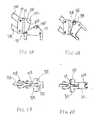
Figure 1 is a perspective view of one embodiment of an instrument assembly of the invention.Figure 2 is a representational view of one embodiment of an instrument assembly of the invention, shown in a coronal plane.Figure 3 is a representational view of one embodiment of an instrument assembly of the invention, shown in a transverse plane.Figure 4 is a perspective view of one embodiment of a goniometer of the invention.Figure 5A is a side view of one embodiment of an adjustment component of a goniometer of the invention in an open, unengaged position.Figure 5B is a side view of one embodiment of an adjustment component of a goniometer of the invention in an engaged position.Figure 6A is a top view of one embodiment of an adjustment component of a goniometer of the invention in an open, unengaged position.Figure 6B is a top view of one embodiment of an adjustment component of a goniometer of the invention in an engaged position.Figure 7A is a side view of one embodiment of femoral neck clamp for use in the instrument assembly of the invention.Figure 7B is an exploded view of one embodiment of femoral neck clamp for use in the instrument assembly of the invention.Figure 8A is a side view of one embodiment of a pin guide for use in the instrument assembly of the invention.Figure 8B is a front view of one embodiment of a pin guide for use in the assembly of the invention.Figure 9 is a perspective view of a pin guide bushing for use in the assembly of the invention.- In the following detailed description of the preferred embodiments, reference is made to the accompanying drawings which form a part hereof, and in which are shown by way of illustration specific embodiments in which the invention may be practiced. It is to be understood that other embodiments may be utilized and structural changes may be made without departing from the scope of the present invention.
- As shown in
Figure 1 , the invention is an assembly for placing aguide pin 180 in afemoral neck 202 of a patient for subsequent use in resurfacing afemoral head 204. The assembly is configured so as to enable the orientation of theguide pin 180 to be established with reference to amedullary guide wire 190. The assembly includes, generally, afemoral neck clamp 10, apin guide 30, and agoniometer 50. Abushing 130 links thepin guide 30 to thegoniometer 50. As indicated in the representational view ofFigure 2 , thefemoral neck clamp 10 is configured to define a pin pointC coinciding with a center of thefemoral neck 202. As shown inFigure 1 , thepin guide 30 attaches to thefemoral neck clamp 10. Thepin guide 30 has apin guide portion 43 which is configured to define a pin guide pathP passing through the pin pointC defined by thefemoral neck clamp 10. Thegoniometer 50 has a medullary guidewire engagement member 60 and a pinguide engagement portion 102. The pinguide engagement portion 102 is configured to maintain a set angle with respect to themedullary guide wire 190. As indicated in the representational view ofFigure 2 , the pinguide engagement portion 102 and thepin guide portion 43 are configured to engage one another such that the goniometer orients the pin guide pathP at the set angle with respect to themedullary guide wire 190. As indicated in the representational view ofFigure 2 , the pinguide engagement portion 102 is adjustably linked to the medullary guidewire engagement member 60 so as to accommodate patients of various sizes. While various adjustable linkage means could be used for this purpose, as indicated by the representational views, a four bar linkage embodiment will discussed in detail below. - In the embodiment shown in
Figure 1 , the pinguide engagement portion 102 of thegoniometer 50 and thepin guide portion 43 of thepin guide 30 are configured to receive apin guide bushing 130 therethrough. The pin guide bushing130 links thegoniometer 50 and thepin guide 30 along the pin pathP. Thepin guide 30 is rotatably attached to thefemoral neck clamp 10, such that thepin guide portion 43 can be selectively rotated through a plurality of guide pin angles or pathsP, with each of the guide pin angles passing through the neck center C defined by thefemoral neck clamp 10. - As shown in
Figure 4 , thegoniometer 50 can have anangle adjustment member 90. As shown inFigures 5A-6B , theangle adjustment member 90 is configured to adjust the pinguide engagement portion 102 between a plurality of set angles. In the embodiment ofFigures 5-6 , theangle adjustment member 90 is configured to adjust the pinguide engagement portion 102 between three set angles, the angles being135 degrees,140 degrees and 145 degrees with respect to themedullary guide wire 190. Theangle adjustment member 90 feature reduces instrument inventory, since it is not necessary to provide separate goniometers having different angles. - The
femoral neck clamp 10 has aring portion 12 and anextension portion 20 extending from thering portion 12. As shown inFigure 7 , thering portion 10 includes a first partial ring portion12A and a second partial ring portion12B. The first partial ring portion12A has afirst extension portion 20A extending therefrom, while the second partial ring portion12B has a second extension portion20B extending therefrom. As shown inFigure 7B , the first andsecond extension portions 20A, 20B are pivotally attached to one another, such as by end bores29 jointed by apivot bolt 28. - The
extension portion 20 of thefemoral neck clamp 10 includes a track22 for rotatable engagement with anattachment base 32 of thepin guide 30. The track22 includes a pair of opposingstops 23 for abutting against a stop member36 of thepin guide 30attachment base 32 to thereby establish a rotation range for thepin guide 30 relative to thefemoral neck clamp 10. The track22 includes atine groove 24 for engaging atine 34 or tines of theattachment base 32 of thepin guide 30 to thereby selectively secure thepin guide 30 in the track22 of thefemoral neck clamp 10. - As shown in
Figure 8A , thepin guide 30 has anattachment base 32. As shown inFigure 8B , theattachment base 32 has abore 33 therethrough for receiving thefemoral neck clamp 10 in a rotatable relationship. At least onetine 34 is provided in theattachment base 32 for selectively engaging acorresponding tine groove 24 in theextension portion 20 of thefemoral neck clamp 10. As shown inFigure8A , a stop member36 extends from theattachment base 32. - The
pin guide 30 includes anextension portion 40, which serves to properly space thepin guide portion 43 from theattachment base 32. In the embodiment ofFigure8A , the extension portion has afirst leg 41 extending from theattachment base 32 and asecond leg 42 extending at an angle, such as a right angle, from thefirst leg 41, and thus forms an L shape. - As shown in
Figure8A , thepin guide portion 43 is positioned at an end of thesecond leg 42. Thepin guide portion 43 has abushing holder 44 having a bushing bore45 therethrough. The bushing bore45 is sized to closely receive thepin guide bushing 130 therethrough. In the embodiment ofFigure 8B , alengthwise slot 46 extends along and communicates with the bushing bore45. - As shown in
Figure 1 , thegoniometer 50 includes a medullary guidewire engagement member 60 for use in operatively mounting thegoniometer 50 on amedullary guide wire 190. The medullary guidewire engagement member 60 has a medullary guide wire bore62 passing therethrough. The medullary guide wire bore62 is configured to closely receive themedullary guide wire 190, such that during use, the medullary guide wire bore62 is substantially coaxial withmedullary guide wire 190. - In the embodiment shown in
Figures 1 and4 , the pinguide engagement portion 102 is adjustably linked to the medullary guidewire engagement member 60 via a four bar linkage arrangement. The four bar linkage includes the medullarywire engagement member 60, asupport member 80, and acentral member 70 between the medullarywire engagement member 60 and thesupport member 80. Thecentral member 70 is pivotally linked to the medullarywire engagement member 60 via a firstupper linkage bar 67A and a first lower linkage bar67B. The thefirst bars 67A, 67B are joined to the medullarywire engagement member 60 bypivot bolts 63A, 63B, and are joined to thecentral member 70 by a set ofcentral pivot bolts 73A, 73B. Thecentral member 70 is further pivotally linked to thesupport member 80 via a secondupper linkage bar 78A and a secondlower linkage bar 78B. The second linkage bars78A, 78B are pivotally linked to thecentral member 70 via thecentral pivot bolts 73A, 73B, and to thesupport member 80 via another set ofpivot bolts 83A, 83B. - In the embodiment shown in
Figures 4-5 , thesupport member 80 has anadjustment portion 84 and anangle adjustment member 90. Theangle adjustment member 90 is configured for selecting between a plurality of angles relative to themedullary guide wire 190. In the embodiment shown inFigure 5 , theangle adjustment member 80 is pivotally91 engaged to theadjustment portion 84. Theadjustment portion 84 has afirst angle indent 85A, asecond angle indent 85B and athird angle indent 85C. Theindents - As shown in
Figure 5B , theangle adjustment member 90 has at least one detent95, which is configured to selectively engage the first, second and third angle indents85A, 85B, 85C for use in selecting an angle for theangle adjustment member 90. In the embodiment ofFigure 5B , theangle adjustment member 90 has anupper detent 95A and a lower detent95B. For ease of use, thedetents 95A, 95B are preferably spring biased plunger detents. As indicated inFigures 5A and 6A , the springbiased plunger detents 95A, 95B are held in their respective housings by a set screw96B. - In the embodiment of
Figures5B and6B , theangle adjustment member 90 has an upper detent housing97A and a lower detent housing97B. InFigure5B , theangle adjustment member 90 is shown in an open or unengaged position, while inFigure6B , theangle adjustment member 90 is engaged to theindents angle adjustment member 90. As shown inFigure5A , the first andthird indents lower indent 85B. Theupper detent 95A is positioned in the upper detent housing97A so as to selectively engage the upper first andthird indents angle adjustment member 90 is pivoted toward thesupport member 80. Likewise, the lower detent95B is positioned in the lower detent housing97B so as to selectively engage the second orlower indent 85B. The open configuration shown inFigure 5B further shows the staggered position of the upper andlower detents 95A, 95B with respect to one another. - In the embodiment shown in
Figure 4 , theengagement portion 102 of the goniometer has anupper arm 104A and alower arm 104B, with thearms opening 103 therebetween. As indicated inFigure 1 , theopening 103 is sized to receive thebushing holder 44 of thepin guide 30. Theupper arm 104A has anupper bushing holder 105A adjacent an end thereof. Theupper bushing holder 105A has an upper bushing bore106A formed therethrough. Thelower arm 104B likewise has a lower bushing holder105B adjacent an end thereof, with a lower bushing bore106B formed therethrough. The upper and lower bushing bores106A, 106B are axially aligned for receipt of thebushing 130. - As indicated in
Figures 1 and2 , thebushing 130 threads through the upper bushing bore106A of thegoniometer 50, the bushing bore 45 of thepin guide 30, and the lower bushing bore106B of thegoniometer 50. Thebushing 130 links thepin guide 30 and thegoniometer 50 to one another such that thebushing 130 is axially aligned along an axis that coincides with the guide pin path P and which passes through the neck centerC defined by thefemoral neck clamp 10. - In the embodiment of
Figure 9 , thebushing 130 has a flared head portion132, abone end 138, and a cylindricalelongated body 134 extending between the head portion132 and theend 138. The cylindricalelongated body 134 has apin bore 135 therethrough. The pin bore135 is configured to closely receive aguide pin 180 for use in driving thepin 180 into thefemoral neck 202 along the pin pathP. Thebone end 138 of thebushing 130 is tapered and serrated. - Methods of setting a
guide pin 180 using the instrument assembly of the invention will now be described. Using techniques known to those of skill in the art, the surgeon accesses a proximal end of the patient's femur. Because the instruments reference off of amedullary guide wire 190, an initial step in the method is to install theguide wire 190. Using techniques known to those of skill in the art, the surgeon places aguide wire 190, such as a 3.2 mm pin, in the piriformis fossa (along the greater trochanter) and drills theguide wire 190 toward the middle of the knee deep enough to obtain stable fixation. This establishes the position of themedullary guide wire 190, which will serve as a reference axis for the remainder of the procedure. As indicated inFigures 1-2 , thegoniometer 50 is configured such that only a short portion of the proximal end of themedullary guide wire 190 is needed for mounting thegoniometer 50 on theguide wire 190. This feature reduces exposure ofwire 190 above the femur, which facilities minimally invasive procedures. - As indicated in the representational view of
Figure 2 , the surgeon places aring portion 12 of afemoral neck clamp 10 around thefemoral neck 202. If necessary, osteophytes are removed from thefemoral neck 202. As indicated inFigure 2 , thering portion 12 should be as tight as possible. As can be seen by comparingFigure 2 andFigure 3 , thering portion 12 tightly encircles the femoral neck in the coronal plane(Figure 2 ) but not in the transverse plane(Figure 3 ). Nonetheless, the tight fit in the coronal plane establishes the neck centerC in all planes. - The
pin guide 30 is attached to theextension portion 20 of thefemoral neck clamp 10. The foregoing step can be performed either before or after setting thefemoral neck clamp 10 on thefemoral neck 202. The configuration of theattachment base 32 and associated components discussed herein with reference toFigures 7-8 facilitates attachment of thepin guide 30 to thefemoral neck clamp 10. - As shown in the representational views of
Figures 2-3 , thepin guide portion 44 of thepin guide 30 serves to establish a pathP that passes through the neck center C defined by thefemoral clamp 10. As indicated inFigures 1-2 , the medullary guidewire engagement member 60 is inserted over the proximal protruding end of themedullary guide wire 190, such that the medullary guide wire bore62 is axially aligned with themedullary guide wire 190. As indicated inFigure 1 , the pinguide engagement portion 102 of thegoniometer 50 is positioned to engage thepin guide portion 43 of thepin guide 30. Due to the adjustment features provided by the four bar linkage arrangement of the embodiment shown inFigure 1 , thegoniometer 50 can be readily adjusted to accommodate the size of the particular patient, while still maintaining a specific guide wire angle between the pin pathP and themedullary guide wire 190. Further, theangle adjustment member 90 can be adjusted to select a particular guide wire angle, such as 140 degrees, relative to themedullary guide wire 190. - As indicated in
Figures 1-2 , thebushing 130 is threaded through the bushing bore45 of thepin guide 30 and the upper and lower bushing bores106A, 106B of thegoniometer 50, which serves to link thegoniometer 50 to thepin guide 30. With the assembly linked in place, the surgeon can finalize alignment of the pin path P by rotating thegoniometer 50 about themedullary guide wire 190, and also by rotating thepin guide 30 about thefemoral neck clamp 10. The pin pathP is ultimately established by the orientation of the bushing bore45 of thepin guide 30. Due to the configuration of the assembly, the pin pathP always passes through the neck center C defined by thefemoral neck clamp 10. The pin pathP also always remains at the particular selected guide wire angle (e.g. 140 degrees) with respect to themedullary guide wire 190. The surgeon will typically aim to orient the pin pathP in the center of the femoral neck, which serves to optimize neck strength, preserve natural anatomic orientation, and minimize the risk of notching during the subsequent step of preparing the femoral head to receive the resurfacing implant. However, the assembly of the invention allows adjustments to be made as needed. For example, if the patient'sfemoral neck 202 is excessively anteverted, the surgeon can reduce the anteversion by repositioning the guide pathP accordingly. Themedullary guide wire 190 angle, which establishes varus/valgus positioning, is typically selected by preoperative templating to pass through the center of the femoral neck. In the embodiment ofFigures 5-6 , theangle adjustment member 90 can be pre-adjusted to a selected guide wire angle, such as135, 140 or 145 degrees, derived from pre-operative templating. However, if necessary, the selected guide wire angle can be reset to a different angle after the assembly is in place on the patient. - Once the desired pin pathP is established, the surgeon drills the
guide pin 180 through thepin guide bushing 130. Theguide pin 180 should be drilled through the lateral cortex in order to insure stable internal fixation during the subsequent step of using theguide pin 180 to prepare thefemoral head 204 for receipt of a femoral head implant. Note that because the position of theguide pin 180 is established with reference to thefemoral neck 202, thefemoral head 204 is ignored during alignment and installation of theguide pin 180. - Once the
guide pin 180 is in thefemoral neck 202, the instrument assembly is removed from the patient. Removal can be accomplished simply by removing thebushing 130, removing thegoniometer 50, and unfastening thefemoral neck clamp 10. Once the assembly has been removed from the patient, the surgeon uses theguide pin 180 to prepare thefemoral head 204, using any of the various resurfacing procedures and instruments known to those of skill in the art. - The sequence of steps can be varied without departing from the spirit and scope of the invention. For example, the
femoral neck clamp 10 can be fitted on thefemoral neck 202 before insertion of themedullary guide wire 190 into thefemur 200. - The assembly may be provided in the form of a kit comprising the various components discussed herein. The components of the kit are preferably arranged in a convenient format, such as in a surgical tray or case. However, the kit components do not have to be packaged or delivered together, provided that they are assembled or collected together in the operating room for use at the time of surgery.
- Although the present invention has been described in terms of specific embodiments, it is anticipated that alterations and modifications thereof will no doubt become apparent to those skilled in the art. It is therefore intended that the following claims be interpreted as covering all alterations and modifications that fall within the true spirit and scope of the invention.
Claims (15)
- An instrument assembly for use in resurfacing a femoral head204, the instrument assembly configured for placing a guide pin180 in a femoral neck202 of a patient with reference to a medullary guide wire190 and a femoral neck clamp10 configured to define a neck centerC of said femoral neck202, the instrument assembly
characterized in that:a pin guide30 attached to the femoral neck clamp10, the pin guide30 having a pin guide portion43, the pin guide portion43 configured to define a pin guide pathP passing through the neck centerC defined by the femoral neck clamp10,a goniometer50, the goniometer50 having a medullary guide wire engagement member60 and a pin guide engagement portion102, the pin guide engagement portion102 adjustably linked to the medullary guide wire engagement member60 so as to accommodate patients of various sizes, the medullary guide wire engagement member60 having a medullary guide wire bore62 passing therethrough, the medullary guide wire bore62 configured to closely receive said medullary guide wire190, the pin guide engagement portion102 configured to maintain a set angle with respect to said medullary guide wire190, andthe pin guide engagement portion102 and the pin guide portion43 configured to engage one another such that the goniometer50 orients the pin pathP at the set angle with respect to said medullary guide wire190. - The instrument assembly ofclaim 1, wherein the goniometer50 further comprises an angle adjustment member90, the angle adjustment member90 configured to adjust the pin guide engagement portion102 between a plurality of set angles.
- The instrument assembly ofclaim 2, wherein the angle adjustment member90 is configured to adjust the pin guide engagement portion102 between three set angles, the angles being135 degrees,140 degrees and145 degrees with respect to said medullary guide wire190.
- The instrument assembly ofclaim 1, wherein the pin guide engagement portion102 of the goniometer50 and the pin guide portion43 of the pin guide30 are configured to receive a pin guide bushing130 therethrough.
- The instrument assembly ofclaim 1, wherein the pin guide30 is rotatably attached to the femoral neck clamp10, such that the pin guide portion43 can be selectively rotated through a plurality of pin path P angles while maintaining the pin pathP through the neck centerC defined by the femoral neck clamp10.
- The instrument assembly ofclaim 1, wherein the femoral neck clamp10 has a ring portion12 and an extension portion20 extending from the ring portion 12,
the ring portion10 including a first partial ring portion12A and a second partial ring portion12B, the first partial ring portion12A having a first extension portion 20A extending therefrom, and the second partial ring portion12B having a second extension portion20B extending therefrom, the first and second extension portions20A, 20B pivotally attached to one another. - The instrument assembly ofclaim 6, wherein the extension portion20 of the femoral neck clamp10 includes a track22 for an attachment base32 of the pin guide30,
the track22 including a pair of opposing stops23 for abutting against a stop member36 of the pin guide30 attachment base32 to thereby establish a rotation range for the pin guide30 relative to the femoral neck clamp10,
the track22 including a tine groove24 for engaging the at least one tine of the attachment base32 of the pin guide30 to thereby selectively secure the pin guide30 in the track22 of the femoral neck clamp10. - The instrument assembly ofclaim 7, wherein the pin guide30 has an attachment base 32, the attachment base32 having a bore33 therethrough, at least one tine34 in the attachment base32, a stop member36 extending from the attachment base32,
an extension portion40, the extension portion having a first leg41 extending from the attachment base32 and a second leg42 extending at an angle from the first leg41, and
the pin guide portion43 positioned at an end of the second leg42, the pin guide portion43 having a bushing holder44 having a bushing bore45 therethrough, and a lengthwise slot46. - The instrument assembly ofclaim 1, wherein the pin guide engagement portion102 is adjustably linked to the medullary guide wire engagement member60 via a four bar linkage, the four bar linkage including the medullary wire engagement member60, a support member80, and a central member70 between the medullary wire engagement member60 and the support member80, the central member70 pivotally linked to the medullary wire engagement member60 via a first upper linkage bar67A and a first lower linkage bar 67B, the central member70 pivotally linked to the support member80 via a second upper linkage bar78A and a second lower linkage bar78B.
- The instrument assembly ofclaim 9, wherein the support member80 has an adjustment portion 84 and an angle adjustment member90, the angle adjustment member 90 configured for selecting between a plurality of set angles.
- The instrument assembly ofclaim 10, wherein the angle adjustment member 90 is pivotally 91 engaged to the adjustment portion84.
- The instrument assembly ofclaim 11, wherein the adjustment portion84 has a first angle indent85A, a second angle indent85B and a third angle indent85C, and the angle adjustment member 90 has at least one detent95, the at least one detent95 positioned to selectively engage at least two of the first, second and third angle indents for use in selecting a set angle from among the plurality of set angles.
- The instrument assembly ofclaim 12, wherein the angle adjustment member90 has an upper detent95A, a lower detent95B, an upper detent housing97A and a lower detent housing97B, the upper and the lower detent housings97A, 97B fixedly positioned on opposing sides of the angle adjustment member90.
- The instrument assembly ofclaim 1, wherein the engagement portion102 has an upper arm104A and a lower arm104B, the upper and lower arms104A, 104B defining an opening103 for receipt of a bushing holder44 of the pin guide30,
the upper arm104A having an upper bushing holder105A adjacent an end thereof, the upper bushing holder105A having an upper bushing bore106A formed therethrough,
the lower arm104B having a lower bushing holder105B adjacent an end thereof, the lower bushing holder105B having a lower bushing bore106B formed therethrough,
the upper and lower bushing bores106A, 106B axially aligned for receipt of a bushing130, and
a pin guide bushing130, the pin guide bushing130 having a flared head portion132, a bone end138, and a cylindrical elongated body134 extending between the head portion132 and the end138, the cylindrical elongated body134 having a through bore135 therethrough, the through bore135 configured to closely receive said guide pin180. - The instrument assembly ofclaim 14, wherein the bone end138 of the pin guide bushing130 is tapered and serrated.
Applications Claiming Priority (1)
| Application Number | Priority Date | Filing Date | Title |
|---|---|---|---|
| US1209007P | 2007-12-07 | 2007-12-07 |
Publications (2)
| Publication Number | Publication Date |
|---|---|
| EP2067443A1true EP2067443A1 (en) | 2009-06-10 |
| EP2067443B1 EP2067443B1 (en) | 2011-02-23 |
Family
ID=40433813
Family Applications (1)
| Application Number | Title | Priority Date | Filing Date |
|---|---|---|---|
| EP08021155ANot-in-forceEP2067443B1 (en) | 2007-12-07 | 2008-12-05 | Pin centering guide with goniometer |
Country Status (4)
| Country | Link |
|---|---|
| US (1) | US8348957B2 (en) |
| EP (1) | EP2067443B1 (en) |
| AT (1) | ATE499052T1 (en) |
| DE (1) | DE602008005095D1 (en) |
Cited By (3)
| Publication number | Priority date | Publication date | Assignee | Title |
|---|---|---|---|---|
| EP2294980A1 (en)* | 2009-09-09 | 2011-03-16 | In Novation B.V. | Hip surgery assembly |
| WO2011151654A1 (en)* | 2010-06-03 | 2011-12-08 | Robert Gordon University | Surgical guide device |
| US8568419B2 (en) | 2010-03-25 | 2013-10-29 | Hipsecure B.V. | Navigation system for orthopaedic surgery |
Families Citing this family (19)
| Publication number | Priority date | Publication date | Assignee | Title |
|---|---|---|---|---|
| US8795287B2 (en)* | 2007-02-08 | 2014-08-05 | Zimmer, Inc. | Targeting device |
| EP2496160B1 (en)* | 2009-11-06 | 2017-08-23 | Mark Crawford | Spinal surgery apparatus and method |
| US20120029523A1 (en)* | 2010-07-29 | 2012-02-02 | Kam Andrew S | Guide pin positioner |
| US20130245632A1 (en)* | 2011-09-13 | 2013-09-19 | The Cleveland Clinic Foundation | Method and apparatus for insertion of an elongate pin into a surface |
| US20150201900A1 (en)* | 2012-01-25 | 2015-07-23 | Mubin I. Syed | Multi-pane imaging transducer associated with a guidewire |
| US10213187B1 (en) | 2012-01-25 | 2019-02-26 | Mubin I. Syed | Method and apparatus for percutaneous superficial temporal artery access for carotid artery stenting |
| WO2014081947A1 (en) | 2012-11-21 | 2014-05-30 | Syed Mubin I | System for the intravascular placement of a medical device |
| CN103519875A (en)* | 2013-10-28 | 2014-01-22 | 韩文冬 | Femur small tuberosity fracture reduction fixator |
| US9636244B2 (en) | 2015-04-09 | 2017-05-02 | Mubin I. Syed | Apparatus and method for proximal to distal stent deployment |
| US10492936B2 (en) | 2015-10-30 | 2019-12-03 | Ram Medical Innovations, Llc | Apparatus and method for improved access of procedural catheter in tortuous vessels |
| US10327929B2 (en) | 2015-10-30 | 2019-06-25 | Ram Medical Innovations, Llc | Apparatus and method for stabilization of procedural catheter in tortuous vessels |
| US10779976B2 (en) | 2015-10-30 | 2020-09-22 | Ram Medical Innovations, Llc | Apparatus and method for stabilization of procedural catheter in tortuous vessels |
| US11020256B2 (en) | 2015-10-30 | 2021-06-01 | Ram Medical Innovations, Inc. | Bifurcated “Y” anchor support for coronary interventions |
| US10173031B2 (en) | 2016-06-20 | 2019-01-08 | Mubin I. Syed | Interchangeable flush/selective catheter |
| US11517348B2 (en)* | 2017-05-03 | 2022-12-06 | Tel Hashomer Medical Research Infrastructure And Services Ltd. | Guide device suitable for performing temporomandibular joint arthroscopy |
| GB2569336B (en)* | 2017-12-13 | 2020-12-30 | Embody Orthopaedic Ltd | Guide for positioning a resurfacing head implant |
| US11007075B2 (en) | 2018-02-18 | 2021-05-18 | Ram Medical Innovations, Inc. | Vascular access devices and methods for lower limb interventions |
| US20240050243A1 (en)* | 2020-12-23 | 2024-02-15 | Formae, Inc. | Instruments and methods for preparing patient recipient site and installing medical implant |
| CN113069250A (en)* | 2021-02-24 | 2021-07-06 | 北京市春立正达医疗器械股份有限公司 | Femoral neck rotation center positioning device |
Citations (6)
| Publication number | Priority date | Publication date | Assignee | Title |
|---|---|---|---|---|
| US4123806A (en) | 1977-01-31 | 1978-11-07 | Regents Of The University Of California | Total hip joint replacement |
| US6156069A (en) | 1999-02-04 | 2000-12-05 | Amstutz; Harlan C. | Precision hip joint replacement method |
| WO2005051209A1 (en) | 2003-11-20 | 2005-06-09 | Wright Medical Technology, Inc. | Guide clamp for guiding placement of a guide wire in a femur |
| FR2863859A1 (en)* | 2003-12-23 | 2005-06-24 | Ct Pulse France Sa | Ancillaire for use in hip prosthesis field, has central medullaire rod implanted temporarily in lower digitalis fossa of femur forming fixed and stable anchoring point corresponding to cervix axis of femur |
| US20050245934A1 (en)* | 2004-03-09 | 2005-11-03 | Finsbury (Development) Limited | Tool |
| WO2007137327A1 (en)* | 2006-05-26 | 2007-12-06 | Ellysian Ltd | Hip resurfacing clamp |
Family Cites Families (5)
| Publication number | Priority date | Publication date | Assignee | Title |
|---|---|---|---|---|
| US245934A (en)* | 1881-08-23 | Apparatus for freeing pumps from air | ||
| US5397323A (en)* | 1992-10-30 | 1995-03-14 | International Business Machines Corporation | Remote center-of-motion robot for surgery |
| US5688284A (en)* | 1996-09-20 | 1997-11-18 | Medicinelodge, Inc. | Variable angle drill guide and ligament fixation method |
| US6390424B1 (en)* | 2000-07-13 | 2002-05-21 | Margo Kidushim | Accessory support device and method |
| US20080109085A1 (en)* | 2006-11-03 | 2008-05-08 | Howmedica Osteonics Corp. | Method and apparatus for hip femoral resurfacing tooling |
- 2008
- 2008-12-05EPEP08021155Apatent/EP2067443B1/ennot_activeNot-in-force
- 2008-12-05DEDE602008005095Tpatent/DE602008005095D1/enactiveActive
- 2008-12-05USUS12/329,131patent/US8348957B2/ennot_activeExpired - Fee Related
- 2008-12-05ATAT08021155Tpatent/ATE499052T1/ennot_activeIP Right Cessation
Patent Citations (6)
| Publication number | Priority date | Publication date | Assignee | Title |
|---|---|---|---|---|
| US4123806A (en) | 1977-01-31 | 1978-11-07 | Regents Of The University Of California | Total hip joint replacement |
| US6156069A (en) | 1999-02-04 | 2000-12-05 | Amstutz; Harlan C. | Precision hip joint replacement method |
| WO2005051209A1 (en) | 2003-11-20 | 2005-06-09 | Wright Medical Technology, Inc. | Guide clamp for guiding placement of a guide wire in a femur |
| FR2863859A1 (en)* | 2003-12-23 | 2005-06-24 | Ct Pulse France Sa | Ancillaire for use in hip prosthesis field, has central medullaire rod implanted temporarily in lower digitalis fossa of femur forming fixed and stable anchoring point corresponding to cervix axis of femur |
| US20050245934A1 (en)* | 2004-03-09 | 2005-11-03 | Finsbury (Development) Limited | Tool |
| WO2007137327A1 (en)* | 2006-05-26 | 2007-12-06 | Ellysian Ltd | Hip resurfacing clamp |
Cited By (4)
| Publication number | Priority date | Publication date | Assignee | Title |
|---|---|---|---|---|
| EP2294980A1 (en)* | 2009-09-09 | 2011-03-16 | In Novation B.V. | Hip surgery assembly |
| US8568419B2 (en) | 2010-03-25 | 2013-10-29 | Hipsecure B.V. | Navigation system for orthopaedic surgery |
| WO2011151654A1 (en)* | 2010-06-03 | 2011-12-08 | Robert Gordon University | Surgical guide device |
| US8979850B2 (en) | 2010-06-03 | 2015-03-17 | Clear Surgical Limited | Surgical guide device |
Also Published As
| Publication number | Publication date |
|---|---|
| US8348957B2 (en) | 2013-01-08 |
| DE602008005095D1 (en) | 2011-04-07 |
| ATE499052T1 (en) | 2011-03-15 |
| EP2067443B1 (en) | 2011-02-23 |
| US20090240253A1 (en) | 2009-09-24 |
Similar Documents
| Publication | Publication Date | Title |
|---|---|---|
| EP2067443B1 (en) | Pin centering guide with goniometer | |
| US4959066A (en) | Femoral osteotomy guide assembly | |
| US9668749B2 (en) | Adjustable revision guide | |
| US8845643B2 (en) | Humeral rotating burr guide | |
| US7104995B2 (en) | Method of preparing an acetabulum for receiving a head of a femoral prosthesis | |
| US6478799B1 (en) | Instruments and methods for use in performing knee surgery | |
| US9078676B2 (en) | Patella drilling system | |
| US20100137924A1 (en) | Tool | |
| US7819879B2 (en) | Guide pin placement for hip resurfacing | |
| JP5697999B2 (en) | System and method for performing a modular revision hip prosthesis | |
| US20140336657A1 (en) | Positioning apparatus and method for a prosthetic implant | |
| US20070162039A1 (en) | Tool | |
| US20090222017A1 (en) | Positioning bracket | |
| JP2021506553A (en) | Minimally invasive hip arthroplasty technology and equipment | |
| US12208022B2 (en) | Positioning device of a surgical instrument for hip arthroplasty surgery | |
| US11583328B2 (en) | Femoral nail and instrumentation system | |
| US10271963B2 (en) | Referencing apparatus and associated methods |
Legal Events
| Date | Code | Title | Description |
|---|---|---|---|
| PUAI | Public reference made under article 153(3) epc to a published international application that has entered the european phase | Free format text:ORIGINAL CODE: 0009012 | |
| AK | Designated contracting states | Kind code of ref document:A1 Designated state(s):AT BE BG CH CY CZ DE DK EE ES FI FR GB GR HR HU IE IS IT LI LT LU LV MC MT NL NO PL PT RO SE SI SK TR | |
| AX | Request for extension of the european patent | Extension state:AL BA MK RS | |
| 17P | Request for examination filed | Effective date:20091210 | |
| GRAP | Despatch of communication of intention to grant a patent | Free format text:ORIGINAL CODE: EPIDOSNIGR1 | |
| AKX | Designation fees paid | Designated state(s):AT BE BG CH CY CZ DE DK EE ES FI FR GB GR HR HU IE IS IT LI LT LU LV MC MT NL NO PL PT RO SE SI SK TR | |
| GRAS | Grant fee paid | Free format text:ORIGINAL CODE: EPIDOSNIGR3 | |
| GRAA | (expected) grant | Free format text:ORIGINAL CODE: 0009210 | |
| AK | Designated contracting states | Kind code of ref document:B1 Designated state(s):AT BE BG CH CY CZ DE DK EE ES FI FR GB GR HR HU IE IS IT LI LT LU LV MC MT NL NO PL PT RO SE SI SK TR | |
| REG | Reference to a national code | Ref country code:GB Ref legal event code:FG4D | |
| REG | Reference to a national code | Ref country code:CH Ref legal event code:EP | |
| REG | Reference to a national code | Ref country code:IE Ref legal event code:FG4D | |
| REF | Corresponds to: | Ref document number:602008005095 Country of ref document:DE Date of ref document:20110407 Kind code of ref document:P | |
| REG | Reference to a national code | Ref country code:DE Ref legal event code:R096 Ref document number:602008005095 Country of ref document:DE Effective date:20110407 | |
| REG | Reference to a national code | Ref country code:NL Ref legal event code:VDEP Effective date:20110223 | |
| LTIE | Lt: invalidation of european patent or patent extension | Effective date:20110223 | |
| PG25 | Lapsed in a contracting state [announced via postgrant information from national office to epo] | Ref country code:LT Free format text:LAPSE BECAUSE OF FAILURE TO SUBMIT A TRANSLATION OF THE DESCRIPTION OR TO PAY THE FEE WITHIN THE PRESCRIBED TIME-LIMIT Effective date:20110223 Ref country code:ES Free format text:LAPSE BECAUSE OF FAILURE TO SUBMIT A TRANSLATION OF THE DESCRIPTION OR TO PAY THE FEE WITHIN THE PRESCRIBED TIME-LIMIT Effective date:20110603 Ref country code:LV Free format text:LAPSE BECAUSE OF FAILURE TO SUBMIT A TRANSLATION OF THE DESCRIPTION OR TO PAY THE FEE WITHIN THE PRESCRIBED TIME-LIMIT Effective date:20110223 Ref country code:SE Free format text:LAPSE BECAUSE OF FAILURE TO SUBMIT A TRANSLATION OF THE DESCRIPTION OR TO PAY THE FEE WITHIN THE PRESCRIBED TIME-LIMIT Effective date:20110223 Ref country code:HR Free format text:LAPSE BECAUSE OF FAILURE TO SUBMIT A TRANSLATION OF THE DESCRIPTION OR TO PAY THE FEE WITHIN THE PRESCRIBED TIME-LIMIT Effective date:20110223 Ref country code:NO Free format text:LAPSE BECAUSE OF FAILURE TO SUBMIT A TRANSLATION OF THE DESCRIPTION OR TO PAY THE FEE WITHIN THE PRESCRIBED TIME-LIMIT Effective date:20110523 Ref country code:GR Free format text:LAPSE BECAUSE OF FAILURE TO SUBMIT A TRANSLATION OF THE DESCRIPTION OR TO PAY THE FEE WITHIN THE PRESCRIBED TIME-LIMIT Effective date:20110524 Ref country code:PT Free format text:LAPSE BECAUSE OF FAILURE TO SUBMIT A TRANSLATION OF THE DESCRIPTION OR TO PAY THE FEE WITHIN THE PRESCRIBED TIME-LIMIT Effective date:20110623 | |
| PG25 | Lapsed in a contracting state [announced via postgrant information from national office to epo] | Ref country code:BG Free format text:LAPSE BECAUSE OF FAILURE TO SUBMIT A TRANSLATION OF THE DESCRIPTION OR TO PAY THE FEE WITHIN THE PRESCRIBED TIME-LIMIT Effective date:20110523 Ref country code:FI Free format text:LAPSE BECAUSE OF FAILURE TO SUBMIT A TRANSLATION OF THE DESCRIPTION OR TO PAY THE FEE WITHIN THE PRESCRIBED TIME-LIMIT Effective date:20110223 Ref country code:NL Free format text:LAPSE BECAUSE OF FAILURE TO SUBMIT A TRANSLATION OF THE DESCRIPTION OR TO PAY THE FEE WITHIN THE PRESCRIBED TIME-LIMIT Effective date:20110223 Ref country code:CY Free format text:LAPSE BECAUSE OF FAILURE TO SUBMIT A TRANSLATION OF THE DESCRIPTION OR TO PAY THE FEE WITHIN THE PRESCRIBED TIME-LIMIT Effective date:20110223 Ref country code:AT Free format text:LAPSE BECAUSE OF FAILURE TO SUBMIT A TRANSLATION OF THE DESCRIPTION OR TO PAY THE FEE WITHIN THE PRESCRIBED TIME-LIMIT Effective date:20110223 Ref country code:SI Free format text:LAPSE BECAUSE OF FAILURE TO SUBMIT A TRANSLATION OF THE DESCRIPTION OR TO PAY THE FEE WITHIN THE PRESCRIBED TIME-LIMIT Effective date:20110223 Ref country code:BE Free format text:LAPSE BECAUSE OF FAILURE TO SUBMIT A TRANSLATION OF THE DESCRIPTION OR TO PAY THE FEE WITHIN THE PRESCRIBED TIME-LIMIT Effective date:20110223 | |
| PG25 | Lapsed in a contracting state [announced via postgrant information from national office to epo] | Ref country code:DK Free format text:LAPSE BECAUSE OF FAILURE TO SUBMIT A TRANSLATION OF THE DESCRIPTION OR TO PAY THE FEE WITHIN THE PRESCRIBED TIME-LIMIT Effective date:20110223 Ref country code:EE Free format text:LAPSE BECAUSE OF FAILURE TO SUBMIT A TRANSLATION OF THE DESCRIPTION OR TO PAY THE FEE WITHIN THE PRESCRIBED TIME-LIMIT Effective date:20110223 | |
| PG25 | Lapsed in a contracting state [announced via postgrant information from national office to epo] | Ref country code:CZ Free format text:LAPSE BECAUSE OF FAILURE TO SUBMIT A TRANSLATION OF THE DESCRIPTION OR TO PAY THE FEE WITHIN THE PRESCRIBED TIME-LIMIT Effective date:20110223 Ref country code:RO Free format text:LAPSE BECAUSE OF FAILURE TO SUBMIT A TRANSLATION OF THE DESCRIPTION OR TO PAY THE FEE WITHIN THE PRESCRIBED TIME-LIMIT Effective date:20110223 Ref country code:SK Free format text:LAPSE BECAUSE OF FAILURE TO SUBMIT A TRANSLATION OF THE DESCRIPTION OR TO PAY THE FEE WITHIN THE PRESCRIBED TIME-LIMIT Effective date:20110223 | |
| PLBE | No opposition filed within time limit | Free format text:ORIGINAL CODE: 0009261 | |
| STAA | Information on the status of an ep patent application or granted ep patent | Free format text:STATUS: NO OPPOSITION FILED WITHIN TIME LIMIT | |
| 26N | No opposition filed | Effective date:20111124 | |
| PG25 | Lapsed in a contracting state [announced via postgrant information from national office to epo] | Ref country code:PL Free format text:LAPSE BECAUSE OF FAILURE TO SUBMIT A TRANSLATION OF THE DESCRIPTION OR TO PAY THE FEE WITHIN THE PRESCRIBED TIME-LIMIT Effective date:20110223 | |
| REG | Reference to a national code | Ref country code:DE Ref legal event code:R097 Ref document number:602008005095 Country of ref document:DE Effective date:20111124 | |
| PG25 | Lapsed in a contracting state [announced via postgrant information from national office to epo] | Ref country code:MC Free format text:LAPSE BECAUSE OF NON-PAYMENT OF DUE FEES Effective date:20111231 | |
| REG | Reference to a national code | Ref country code:IE Ref legal event code:MM4A | |
| PG25 | Lapsed in a contracting state [announced via postgrant information from national office to epo] | Ref country code:IE Free format text:LAPSE BECAUSE OF NON-PAYMENT OF DUE FEES Effective date:20111205 | |
| PG25 | Lapsed in a contracting state [announced via postgrant information from national office to epo] | Ref country code:MT Free format text:LAPSE BECAUSE OF FAILURE TO SUBMIT A TRANSLATION OF THE DESCRIPTION OR TO PAY THE FEE WITHIN THE PRESCRIBED TIME-LIMIT Effective date:20110223 | |
| PG25 | Lapsed in a contracting state [announced via postgrant information from national office to epo] | Ref country code:LU Free format text:LAPSE BECAUSE OF NON-PAYMENT OF DUE FEES Effective date:20111205 | |
| PG25 | Lapsed in a contracting state [announced via postgrant information from national office to epo] | Ref country code:IS Free format text:LAPSE BECAUSE OF FAILURE TO SUBMIT A TRANSLATION OF THE DESCRIPTION OR TO PAY THE FEE WITHIN THE PRESCRIBED TIME-LIMIT Effective date:20110223 | |
| REG | Reference to a national code | Ref country code:CH Ref legal event code:PL | |
| PG25 | Lapsed in a contracting state [announced via postgrant information from national office to epo] | Ref country code:TR Free format text:LAPSE BECAUSE OF FAILURE TO SUBMIT A TRANSLATION OF THE DESCRIPTION OR TO PAY THE FEE WITHIN THE PRESCRIBED TIME-LIMIT Effective date:20110223 | |
| PG25 | Lapsed in a contracting state [announced via postgrant information from national office to epo] | Ref country code:CH Free format text:LAPSE BECAUSE OF NON-PAYMENT OF DUE FEES Effective date:20121231 Ref country code:LI Free format text:LAPSE BECAUSE OF NON-PAYMENT OF DUE FEES Effective date:20121231 Ref country code:HU Free format text:LAPSE BECAUSE OF FAILURE TO SUBMIT A TRANSLATION OF THE DESCRIPTION OR TO PAY THE FEE WITHIN THE PRESCRIBED TIME-LIMIT Effective date:20110223 | |
| PG25 | Lapsed in a contracting state [announced via postgrant information from national office to epo] | Ref country code:IT Free format text:LAPSE BECAUSE OF NON-PAYMENT OF DUE FEES Effective date:20121205 | |
| REG | Reference to a national code | Ref country code:DE Ref legal event code:R082 Ref document number:602008005095 Country of ref document:DE Representative=s name:HIRSCH & ASSOCIES S.E.P., FR | |
| REG | Reference to a national code | Ref country code:DE Ref legal event code:R081 Ref document number:602008005095 Country of ref document:DE Owner name:MICROPORT ORTHOPEDICS HOLDINGS INC., NL Free format text:FORMER OWNER: WRIGHT MEDICAL TECHNOLOGY INC., ARLINGTON, TENN., US Effective date:20150202 Ref country code:DE Ref legal event code:R082 Ref document number:602008005095 Country of ref document:DE Representative=s name:HIRSCH & ASSOCIES S.E.P., FR Effective date:20150202 | |
| REG | Reference to a national code | Ref country code:FR Ref legal event code:TP Owner name:MICORPORT ORTHOPEDICS HOLDINGS INC., NL Effective date:20150320 | |
| REG | Reference to a national code | Ref country code:GB Ref legal event code:732E Free format text:REGISTERED BETWEEN 20150723 AND 20150729 | |
| REG | Reference to a national code | Ref country code:FR Ref legal event code:PLFP Year of fee payment:8 | |
| REG | Reference to a national code | Ref country code:FR Ref legal event code:PLFP Year of fee payment:9 | |
| REG | Reference to a national code | Ref country code:FR Ref legal event code:PLFP Year of fee payment:10 | |
| PGFP | Annual fee paid to national office [announced via postgrant information from national office to epo] | Ref country code:DE Payment date:20191119 Year of fee payment:12 | |
| PGFP | Annual fee paid to national office [announced via postgrant information from national office to epo] | Ref country code:FR Payment date:20191115 Year of fee payment:12 | |
| PGFP | Annual fee paid to national office [announced via postgrant information from national office to epo] | Ref country code:GB Payment date:20191206 Year of fee payment:12 | |
| REG | Reference to a national code | Ref country code:DE Ref legal event code:R119 Ref document number:602008005095 Country of ref document:DE | |
| GBPC | Gb: european patent ceased through non-payment of renewal fee | Effective date:20201205 | |
| PG25 | Lapsed in a contracting state [announced via postgrant information from national office to epo] | Ref country code:FR Free format text:LAPSE BECAUSE OF NON-PAYMENT OF DUE FEES Effective date:20201231 | |
| PG25 | Lapsed in a contracting state [announced via postgrant information from national office to epo] | Ref country code:GB Free format text:LAPSE BECAUSE OF NON-PAYMENT OF DUE FEES Effective date:20201205 Ref country code:DE Free format text:LAPSE BECAUSE OF NON-PAYMENT OF DUE FEES Effective date:20210701 |