EP2067269B1 - Distributed antenna communications system and method of implementing thereof - Google Patents
Distributed antenna communications system and method of implementing thereofDownload PDFInfo
- Publication number
- EP2067269B1 EP2067269B1EP07811395.8AEP07811395AEP2067269B1EP 2067269 B1EP2067269 B1EP 2067269B1EP 07811395 AEP07811395 AEP 07811395AEP 2067269 B1EP2067269 B1EP 2067269B1
- Authority
- EP
- European Patent Office
- Prior art keywords
- port
- repeater hub
- hub
- base station
- antenna
- Prior art date
- Legal status (The legal status is an assumption and is not a legal conclusion. Google has not performed a legal analysis and makes no representation as to the accuracy of the status listed.)
- Active
Links
- 238000004891communicationMethods0.000titleclaimsdescription42
- 238000000034methodMethods0.000titleclaimsdescription15
- 238000012545processingMethods0.000claimsdescription3
- 108091006146ChannelsProteins0.000description74
- 238000005259measurementMethods0.000description20
- 238000009434installationMethods0.000description7
- 238000010295mobile communicationMethods0.000description4
- 230000001413cellular effectEffects0.000description3
- 238000006243chemical reactionMethods0.000description3
- 230000000694effectsEffects0.000description3
- 230000003321amplificationEffects0.000description2
- 230000002457bidirectional effectEffects0.000description2
- 230000005540biological transmissionEffects0.000description2
- 238000001514detection methodMethods0.000description2
- 230000006855networkingEffects0.000description2
- 238000003199nucleic acid amplification methodMethods0.000description2
- 230000003213activating effectEffects0.000description1
- 230000003044adaptive effectEffects0.000description1
- 230000015556catabolic processEffects0.000description1
- 230000010267cellular communicationEffects0.000description1
- 239000004020conductorSubstances0.000description1
- 238000006731degradation reactionMethods0.000description1
- 238000005516engineering processMethods0.000description1
- 230000002708enhancing effectEffects0.000description1
- 238000001914filtrationMethods0.000description1
- 238000007726management methodMethods0.000description1
- 230000000737periodic effectEffects0.000description1
- 238000012360testing methodMethods0.000description1
- 230000000007visual effectEffects0.000description1
Images


Classifications
- H—ELECTRICITY
- H04—ELECTRIC COMMUNICATION TECHNIQUE
- H04W—WIRELESS COMMUNICATION NETWORKS
- H04W88/00—Devices specially adapted for wireless communication networks, e.g. terminals, base stations or access point devices
- H04W88/08—Access point devices
- H04W88/085—Access point devices with remote components
- H—ELECTRICITY
- H04—ELECTRIC COMMUNICATION TECHNIQUE
- H04B—TRANSMISSION
- H04B7/00—Radio transmission systems, i.e. using radiation field
- H04B7/14—Relay systems
- H04B7/15—Active relay systems
- H04B7/155—Ground-based stations
- H04B7/15528—Control of operation parameters of a relay station to exploit the physical medium
Definitions
- the present inventionrelates to the field of wireless communications and, more particularly, to a distributed antenna system for wireless communications.
- a conventional distributed antenna systemprovides indoor coverage for wireless communications. Transmitted power is divided among several antennas in distributed indoor locations so as to provide a large coverage area using less transmitted power than would be required by a single antenna system.
- the antennas of a typical DASare connected to a cellular base station and are used for cellular mobile communications.
- a DAScan be implemented using passive or active components.
- a passive DASis implemented using passive splitters and, to minimize signal degradation between the base station and antennas, large diameter coaxial cables are typically employed.
- Installation of a conventional passive DASrequires a planning phase that includes site surveys and system set-up by trained experts in order to ensure that the coverage area and signal strength is suitable throughout the system. Accordingly, passive DAS systems tend to be expensive to implement.
- An active DASemploys active amplifiers and, in some cases, frequency converters that reduce a radio frequency (RF) signal from the base station to an intermediate frequency (IF) for communication to antenna units. At the antenna units, the IF signals are up-converted to RF again.
- RFradio frequency
- IFintermediate frequency
- Such active DAS implementationsrequire only thin coaxial cable, though the performance tends to be improved over that of passive DAS implementations. So that the active DAS is able to accommodate various communication channels and frequencies used by mobile equipment and base stations, the active components need to process a wide range of frequency bands. Due to the requirement for active components that process a wide range of frequency bands, active DAS systems also tend to be expensive to implement.
- a distributed antenna devicefor intermediate frequency conversion/process which comprises a distributed antenna module including a plurality of antenna modules packaged therein, each for transmitting and receiving signals to/from a subscriber terminal through a low-power antenna, a hub unit for transmitting and receiving signals to/from a base transceiver station through a certain antenna, and a coaxial cable connected between the hub unit and the distributed antenna module for transferring signals therebetween.
- the distributed antenna devicehas the effect of minimizing the number of dead zones and maximizing the entire antenna output capacity with lower power than conventional outdoor switching centers.
- a distributed adaptive repeater systemincludes a donor unit, two or more coverage units, and an intelligent hub.
- the donor unitoperates to maintain bidirectional wireless communication with a base station of a wireless communications network.
- Each coverage unitmaintains bidirectional wireless communication with transceivers located within a respective coverage area, and is further adapted to independently control a signal path gain to ensure stability of a respective feedback loop to the donor unit.
- the intelligent hubis operatively coupled between the donor unit and the coverage units, and adapted to monitor a status of each coverage unit.
- a repeaterfor enhancing performance of a TDMA mobile radio system in poor signal areas has a bank of frequency agile, single channel amplifiers, and controller.
- the controllerscans the channel of the band and, upon identifying a channel carrying traffic, enables one of the amplifier units to operate on that channel.
- Each of the amplifier unitsincludes a time slot activity detector for detecting which time slot of a channel is active.
- the output of the activity detectoris passed to a logic control module, which controls the amplification of an active time slot via a time slot gate and power unit.
- a hybrid electronic radio repeatercomprising an antenna means for receiving a select, narrow frequency band of radio wave signals, the radio wave signal(s) being transmitted from discrete sources wherein the radio wave signals contain source, status and control information.
- a radio frequency amplifier meansfilters and amplifies the radio signals and passes them to a mixing means.
- the mixing meansincluding a local oscillator means, combines the radio frequency signals with the local oscillator signals to produce intermediate frequency signals.
- the intermediate frequency signalsare narrow filtered causing tuning by local oscillator tuning means.
- An intermediate frequency amplifier meansdetects and amplifies the IF signals and generates a signal strength level indication in response thereto.
- control meansthe control means being an intelligent unit capable of discerning information and generating responses thereto, monitors the signal strength level indications and also initiates the tuning voltage level of said narrow frequency band local oscillator tuning, for the presence of select radio wave signals, the control means tuning the hybrid radio repeater in response to the presence of the select signals.
- a distributed antenna systemcomprises: a base station configured for communication with a telecommunications network; a multi-port repeater hub connected to the base station to receive a communications signal from the base station and to distribute the communications signal to a plurality of ports of the multi-port repeater hub, the multi-port repeater hub comprising a scanner for scanning a plurality of frequency channels to identify one or more channels of the communications signal received from the base station; and a plurality of antenna units, each coupled to one of the ports of the multi-port repeater hub.
- FIG. 1illustrates a distributed antenna communications system 100 in accordance with an embodiment of the present invention.
- a pico base transceiver subsystem(which may also be referred to as a BTS or base station) 102 is communicatively coupled to a communications network 104 via a backhaul link 106.
- the backhaul 106is coupled to a base station controller (BSC) 108, which is, in turn, coupled to a mobile switching center (MSC) 110.
- BSCbase station controller
- MSCmobile switching center
- the MSC 110is coupled to a public switched telephone network (PSTN) 112 (e.g. for voice communications) and may also be coupled to the Internet 114 (e.g. for data communications).
- PSTNpublic switched telephone network
- Internet 114e.g. for data communications
- the BSC 108may perform various conventional functions including radio channel allocation, call handovers among base stations, configuring the base station 102, handling alarms and performing network management functions.
- the MSC 110may perform various conventional functions including circuit switching, and providing applications and call features to mobile subscribers, such as call ringing and roaming.
- certain of the features conventionally performed by the BSC 108 and MSC 110may instead be performed by the base station 102.
- the base station 102may include a local server which is configured with a Linux operating system to perform these functions.
- the base station 102is also communicatively coupled to multi-port repeater hub 116 by, for example, a wireless link.
- the base station 102may be located at the site of a cellular service provider.
- the hub 116is communicatively coupled to a plurality of antenna units 118. Together, the antenna units form one or more coverage areas.
- the hub 116 and antenna units 118are located indoors.
- the hub 116may be located in a utility closet of commercial building, while the antenna units 118 may be distributed throughout the building so as to form one or more coverage areas that substantially include the occupied areas within the building.
- the antenna units 118are coupled to the hub 116 by links 122.
- the links 122comprise cabling and connectors that are commonly used for computer networking within commercial buildings, such as CAT 5 cable and RJ-45 connectors or coaxial cables (e.g., "thin" coax).
- the hub 116 and antenna units 118may be installed in a building using cabling that is pre-existing in the building.
- Mobile communications equipment 120within a coverage area is communicatively coupled to the communications network 104 via one or more of the antenna units 118, the hub 116, the base station 102 and the backhaul 106.
- the base station 102may be a pico base station.
- the pico base stationoutputs low power (i.e. less than one watt), comprises a single transceiver unit and uses an Internet protocol (IP) backhaul connection in which voice signals are converted to IP packets for the communication via the backhaul 106.
- IPInternet protocol
- the pico base stationmay use a T1 or E1 connection for the backhaul 106.
- Communications via the pico base station 102may be within a single channel of a particular communications band.
- CDMA communications in the 1900 MHz frequency bandi.e. 1850-1910 MHz uplink and 1930-1990 MHz downlink
- the pico base station 102may operate within a single of one of these 1.25 MHz channels for each of the uplink and downlink.
- the base station 102may operate in a single 200 kHz GSM channel within the 850 MHz frequency band (i.e. 824-849 MHz uplink and 869-894 MHz downlink).
- the base station 102may be macro base station or a micro base station.
- the macro base stationcomprises multiple transceiver units, outputs high power (i.e. 10 watts or more) and is communicatively coupled to the communications network 104 via the backhaul 106 which includes one or more T1 connections (in the United States) or E1 connections (in Europe).
- the micro base stationcomprises multiple transceiver units and is communicatively coupled to a telephone network via a backhaul connection.
- a micro base stationoutputs relatively low power (i.e. 1-2 watts) to the antennas.
- Multiple base stations 102may be coupled to the multi-port repeater hub 116.
- two or more pico base stations, each operating in a respective uplink and downlink channelmay be communicatively coupled to the hub 116.
- the multiple base stations 102may also be communicatively coupled to the base station controller 108 or to one or more different base station controllers.
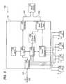
- FIG 2illustrates the multi-port repeater hub 116 of Figure 1 in accordance with an embodiment of the present invention.
- the hub 116includes a base station port 124 which is configured to be communicatively coupled to the base station 102 ( Figure 1 ) or to multiple base stations 102, e.g., via one or more wireless links.
- the base station port 124is communicatively coupled to a signal regenerator 126.
- the signal regenerator 126receives downlink communications signals from the base station port 124 and distributes the signals to distribution ports 128.
- the signal regenerator 126may also perform signal processing functions, such as filtering and amplifying. From the distribution ports 128, the signals are provided to the antenna units 118 ( Figure 1 ).
- Uplink signals from the antenna units 118are received at the distribution ports 128.
- the signal regenerator 126receives the uplink communication signals from the distribution ports 128 and provides them to the base station port 124.
- the uplink signalsare received by the base station 102 from the base station port 124. If the hub 116 receives multiple signals from different base stations, these signals may be combined. For example, a combiner may be coupled to the port 124 to combine the signals prior to being passed to other components of the hub 116.
- the signal regenerator 126performs frequency conversion by converting radio frequency (RF) signals received from the base station port 124 to intermediate frequency (IF) signals which are provided to the distribution ports 128. In this case, the signal regenerator 126 also converts IF signals received from the distribution ports 128 to RF signals which are provided to the base station port 124.
- RFradio frequency
- IFintermediate frequency
- the signal regenerator 126converts RF signals received from the base station port to baseband signals which are then provided to the distribution ports 128.
- the RF signalsmay be separated into in-phase (I) and quadrature (Q) signal components that are then digitally sampled and multiplexed for transmission at baseband to the distribution ports 128.
- the signal regenerator 126may also convert baseband signals (e.g., I and Q digital signal components) received from the distribution ports 128 to RF for provision to the base station port 124. Rather than multiplexing the I and Q signals, they may be communicated separately (e.g., using separate conductors within a CAT-5 cable).
- the multi-port hub 116may include a channel scanner 130 for performing channel scanning functions and a controller 132 for controlling operation of the hub 116.
- the scanner 130intercepts the signal(s) received from the base station 102 at the base station port 124 in order to identify one or more active channels in which the base station 102 operates, or in the case of multiple base stations, the channels in which each of the base stations operates.
- the scanner 130may report its measurement results to the hub controller 132 which then configures the signal regenerator 126 to operate on the one or more identified channels. This may include setting a center frequency and bandwidth of filters, amplifiers and other signal processing elements of the signal regenerator 126 for the identified channels.
- the channel identification and configuration functionsare performed by the hub 116 automatically (i.e. without user intervention) so as to facilitate implementation of the distributed antenna system 100.
- Figure 3illustrates a method 134 of selecting and setting frequency bandwidth in a distributed antenna system in accordance with an embodiment of the present invention.
- the hub 116( Figure 2 ) includes appropriate software and/or hardware to perform the steps of the method 134.
- an installerdoes not need to manually configure the hub 116. This makes installation and implementation of the system 100 easier and tends to avoid the need for a specially-trained expert to install the system 100.
- scanning of the channelsis initiated.
- scanning of the channelsmay be initiated in response to the hub 116 being connected to the base station 102, or upon the hub 116 being powered on.
- scanning of the channelsmay be initiated upon detection of a loss of the signal from the base station 102 or at periodic intervals.
- the channelsare scanned. This may be accomplished by the scanner 130 scanning across a frequency range (e.g., the 1900 MHz band) in increments that are no greater than a channel bandwidth (e.g., 200 kHz) and measuring received signal strength (i.e. RSSI) at each measurement frequency.
- a frequency rangee.g., the 1900 MHz band
- RSSIreceived signal strength
- a particular channel in which the base station 102 transmits a signal to the hub 116can be identified since it can be expected to have a higher measured received signal strength as compared to other channels.
- the frequency range of interestmay be divided into a number m of intervals that are no greater than the channel bandwidth. Then, a variable n may be initialized to a value of 0, indicating the first interval.
- the received signal strengthmay be measured and recorded. Then, the variable n may be incremented by one so that it is equal to 1. While the value of the variable n is equal to 1, the received signal strength may be measured and recorded. This process may then be repeated for each interval until the value of n is equal to m, which indicates that the entire frequency range of interest has been scanned.
- step 140once the one or more downlink channels are identified through scanning, the signal regenerator 126 is configured to operate on these downlink channels and to operate on a corresponding uplink channel for each downlink channel. This may be accomplished by the hub controller 132 setting one or more appropriate parameters of the signal regenerator 126 which are used to tune frequency conversion and amplification circuits of the signal regenerator 126. Alternatively, rather than identifying all of the active channels before the signal regenerator 126 is configured, the signal regenerator 126 may be configured to operate on a particular channel as soon as the channel is identified and while scanning of remaining channels continues.
- the base station 102transmits in only one uplink and one downlink channel.
- the single uplink and single downlink channelsare identified and the regenerator 126 is appropriately configured.
- configuring the signal regenerator 126may also include setting the channel bandwidth.
- the channel bandwidthis fixed.
- the bandwidthmay be fixed at 5 MHz, which is sufficiently wide to accommodate the channel width for common cellular communications protocols, such as GSM (which requires a 200 kHz channel bandwidth), CDMA (which requires a 1.25 MHz channel bandwidth) and UMTS (which requires a 5 MHz channel bandwidth).
- the DAS system 100may set the bandwidth based on the detected bandwidth and/or protocol of the signal.
- the scanner 130 and/or hub controller 132may also test the received signal to identify the bandwidth of its channel(s) which may be different depending upon the protocol with which it operates.
- the scanner 130detects a GSM signal, it sets the bandwidth to 200 kHz; if it detects a CDMA signal, it sets the bandwidth to 1.25 MHz; if it detects a UMTS signal, it sets the bandwidth to 5 MHz, and so on. If the hub 116 receives multiple adjacent or closely-spaced channels, the bandwidth of the signal regenerator 126 may be adjusted to encompass the multiple channels. For example, if three CDMA channels of 1.25 MHz bandwidth are adjacent, the bandwidth should be set to at least 3.75 MHz so that all three channels are encompassed.
- the protocolis identified by determining the approximate channel width.
- the channel scanningis performed at intervals that are sufficiently small that the narrowest channel width of interest can be detected. For example, assume that 200 kHz, which is the channel width for GSM, is the narrowest channel width of interest.
- a GSM signalwill result in several low value measurements, indicating inactive channels, and for an active channel, a single signal strength measurement with a higher value will be immediately preceded by a medium value signal strength measurement and immediately followed by a medium value signal strength measurement. These two medium strength adjacent measurements reflect sidebands.
- the sidebandscan be expected to be detected as two medium value signal strength measurements immediately preceding the high value measurements and two medium value signal strength measurements immediately following the high value measurements.
- the sidebandscan be expected to be detected as two medium value signal strength measurements immediately preceding the high value measurements and two medium value signal strength measurements immediately following the high value measurements.
- the sidebandscan be expected to be detected as two medium value signal strength measurements immediately preceding the high value measurements and two medium value signal strength measurements immediately following the high value measurements.
- the channel bandwidthis 5.0 MHz or approximately 25 times 200 kHz.
- the sidebandscan be expected to be detected as several medium value signal strength measurements immediately preceding the high value measurements and several medium value signal strength measurements immediately following the high value measurements.
- FIG 4illustrates an antenna unit 118 in accordance with an embodiment of the present invention.
- the antenna unit 118includes an interface port 142 which is configured to be communicatively coupled to the hub 116 ( Figure 1 ) via links 122 ( Figure 1 ).
- the antenna unit 118includes a frequency converter 144, which may convert IF or baseband signals received from the hub 116 via the interface 142 into RF signals for transmission via an antenna 146 to mobile communications equipment 120.
- RF signals received by the antenna 146 from mobile communications equipment 120may be converted to IF or baseband for communication to the hub 116.
- the antenna unit 118may also include a controller 148 for controlling operation of the antenna unit 118.
- the antenna unit controller 148receives a message from the hub 116 which identifies the uplink and downlink channels in which the base station 102 operates.
- the frequency converter 144may be configured to send signals to the antenna 146 and to receive signals from the antenna 146 using these same channels.
- the antenna 146 of the antenna unit 118is integrated with a housing for the antenna unit 118 such that the antenna 146 and house are one-piece and no additional step is required to set up the antenna 146 (other than installing the antenna unit 118). This also makes installation and implementation of the system 100 easier and tends to avoid the need for a specially-trained expert to install the system 100.
- the DAS system 100may use cabling and connectors that are commonly used for computer networking within commercial buildings, such as CAT 5 cable and RJ-45 connectors or coaxial cable. These cables typically run from a telecommunications utility room or closet to offices and other work spaces within a commercial building. These existing cables may be used as the links 122 may be used to communicatively connect the hub 116 to each of the antenna units 1 18. As such, the hub 116 and antenna units 118 may be installed in a building using cabling that is pre-existing in the building. This makes installation and implementation of the system 100 easier and tends to avoid the need for a specially-trained expert to install the system 100.
- each antenna unit 118may include a connection indicator 150 for providing an indication of a correct connection between the hub 116 and the antenna unit 118.
- Each antenna unit 118may be plugged into an RJ-45 outlet which is connected to the hub 116 via a cable (e.g., a CAT 5 cable). The antenna units 118 may thus receive power from the hub 116 via the cable and outlet such that no additional power source is needed for the antenna units 118. It is known that power may be delivered using Ethernet cables in accordance with Power over Ethernet (POE) technology.
- POEPower over Ethernet
- connection indicator 150When this power source is sensed by the connection indicator 150 (e.g., by sensing current or voltage), a first light emitting diode (LED) of the connection indicator 150 may be illuminated.
- the connection indicator 150may also sense whether the antenna unit 118 is able to exchange communication messages with the hub 116 (e.g., the messages may be exchanged between the hub controller 132 and the antenna unit controller 148). If so, a second LED of the connection indicator 150 maybe illuminated. This also makes installation and implementation of the system 100 easier and tends to avoid the need for a specially-trained expert to install the system 100. Rather than illuminating the first and second LEDs, first and second acoustic tones may be emitted by the connection indicator 150 to make the corresponding indications.
- the hub 116may also include a connection indicator 152 ( Figure 2 ) in each of the distribution ports 128.
- a connection indicator 152( Figure 2 ) in each of the distribution ports 128.
- a connection indicator 152senses power being drawn by the antenna unit 118, (e.g., by sensing current)
- a first LED of the connection indicator 152may be illuminated.
- the connection indicator 152may also sense whether the hub 116 is able to exchange communication messages with the antenna unit 118. If so, a second LED of the connection indicator 152 may be illuminated. Rather than illuminating the first and second LEDs, first and second acoustic tones may be emitted by the connection indicator 152 to make the corresponding indications.
- signal power at each antenna unit 118is adjusted automatically so that signal loss between the hub 116 and each antenna unit 118 is compensated independently of the amount of loss present between the hub 116 and a particular antenna unit 118. This may be accomplished for the downlink by employing automatic gain control circuitry in the antenna unit controller 148 and/or frequency converter 144 in each antenna unit 118 so that the antenna unit 118 outputs a predetermined power level to its antenna 146 regardless of the signal power received from the hub 116.
- the power level for signals sent by each antenna unit 118 to the hub 116may be adjusted by a similar amount as is the downlink signal. This assumes that cable loss is similar in both directions between the hub 116 and each antenna unit 118.
- the uplink and downlink channelsmay be at different IF frequencies, the cable loss may be different for the uplink and the downlink. Accordingly, the power level for the uplink may also be adjusted to compensate for this expected difference in the amount of loss.
- This automatic signal gain controlalso makes installation and implementation of the system 100 easier and tends to avoid the need for a specially-trained expert to install the system 100.
- the hub controller 132may measure round-trip signal loss between the hub 116 and each of the antenna units 118 (e.g., by activating a loop switch in each antenna unit 118). The hub controller 132 may use this information to automatically set downlink transmit levels in the hub 116. The hub controller 116 may also send a message to each antenna unit 118 which causes the antenna unit 118 to set its uplink transmit power level based on the measured round-trip signal loss. The downlink and uplink power levels between the hub 116 and each antenna unit 118 may be set independently of the others since each may experience different losses. This automatic setting of downlink and uplink power levels also makes installation and implementation of the system 100 easier and tends to avoid the need for a specially-trained expert to install the system 100.
- the hub 116includes a wireless modem 154.
- the modemmay send and receive messages via the base station 102 and network 104 to and from an operating center of a network operator. For example, control messages may be received by the modem which cause the output power of the hub 116 and antenna units 118 to be set by the network operator based on round-trip signal loss measured by the hub 16 or based on other measured parameters.
- the network operatormay also receive and respond to alarm messages that identify fault conditions in the DAS system 100.
- the hub 116may be communicatively coupled to the network 104 via a network connection, such as Ethernet, rather than by the modem 154 for communicating control and alarm messages between the hub 116 and the operating center of the network operator.
- Figure 5illustrates a distributed antenna communications system 156 in accordance with an alternative embodiment of the present invention. The system 156 performs the same functions as the system 100 described above with the following differences.
- the hub 116is communicatively coupled to the network 104 via a connector 158 and cable 160.
- the cable 160may be connected to a base station controller (e.g., BSC 108 of Figure 1 ).
- the connector 158may be coupled to a network switch 162, such as an Ethernet network packet switch.
- the switch 162may be connected to the controller 132 and to a connector 164.
- the base station 102is communicatively coupled to the hub 116 via the port 124 via a link 166.
- the link 166may be a wireless link as in Figure 1 .
- the base station 102may also be communicatively coupled to the hub 116 via a link 168 and the connector 164.
- the link 168is a network link such as an Ethernet link.
- the base station 102is communicatively coupled to the network 104 via the hub 116 (via the cables 160 and 168 and the switch 162) rather than being directly connected to the network 104 as in Figure 1 . Accordingly, the cables 160, 168 and switch 162 serves as a backhaul for the base station 102 and hub 116. Also, communications between the controller 132 and the network 104 and between the controller 132 and the base station 102 are via the switch 162. Multiple base stations 102 may be connected to the hub 116 and, thus, multiple base stations 102 may be communicatively coupled to the network 104 via the hub 116 and switch 162. For example, a separate port of the switch 162 may be dedicated to each such base station.
- FIG. 5also shows a server 170 which may be coupled to the switch 162.
- the server 170may comprise a general-purpose computer system and storage and may include an operating system such as Linux.
- the server 170may provide additional functionality to the hub 116. For example, certain of the features conventionally performed by the BSC 108 and MSC 110 of the network 104 may instead be performed by the hub 116 in conjunction with the server 170.
Landscapes
- Engineering & Computer Science (AREA)
- Computer Networks & Wireless Communication (AREA)
- Signal Processing (AREA)
- Mobile Radio Communication Systems (AREA)
- Radio Relay Systems (AREA)
Description
- The present invention relates to the field of wireless communications and, more particularly, to a distributed antenna system for wireless communications.
- A conventional distributed antenna system (DAS) provides indoor coverage for wireless communications. Transmitted power is divided among several antennas in distributed indoor locations so as to provide a large coverage area using less transmitted power than would be required by a single antenna system. The antennas of a typical DAS are connected to a cellular base station and are used for cellular mobile communications.
- A DAS can be implemented using passive or active components. A passive DAS is implemented using passive splitters and, to minimize signal degradation between the base station and antennas, large diameter coaxial cables are typically employed. Installation of a conventional passive DAS requires a planning phase that includes site surveys and system set-up by trained experts in order to ensure that the coverage area and signal strength is suitable throughout the system. Accordingly, passive DAS systems tend to be expensive to implement.
- An active DAS employs active amplifiers and, in some cases, frequency converters that reduce a radio frequency (RF) signal from the base station to an intermediate frequency (IF) for communication to antenna units. At the antenna units, the IF signals are up-converted to RF again. Such active DAS implementations require only thin coaxial cable, though the performance tends to be improved over that of passive DAS implementations. So that the active DAS is able to accommodate various communication channels and frequencies used by mobile equipment and base stations, the active components need to process a wide range of frequency bands. Due to the requirement for active components that process a wide range of frequency bands, active DAS systems also tend to be expensive to implement.
- Disclosed in United States application
2002/0103012 is a distributed antenna device for intermediate frequency conversion/process which comprises a distributed antenna module including a plurality of antenna modules packaged therein, each for transmitting and receiving signals to/from a subscriber terminal through a low-power antenna, a hub unit for transmitting and receiving signals to/from a base transceiver station through a certain antenna, and a coaxial cable connected between the hub unit and the distributed antenna module for transferring signals therebetween. According to this invention, the distributed antenna device has the effect of minimizing the number of dead zones and maximizing the entire antenna output capacity with lower power than conventional outdoor switching centers. - Disclosed in United States application
2005/0176368 is a distributed adaptive repeater system includes a donor unit, two or more coverage units, and an intelligent hub. The donor unit operates to maintain bidirectional wireless communication with a base station of a wireless communications network. Each coverage unit maintains bidirectional wireless communication with transceivers located within a respective coverage area, and is further adapted to independently control a signal path gain to ensure stability of a respective feedback loop to the donor unit. The intelligent hub is operatively coupled between the donor unit and the coverage units, and adapted to monitor a status of each coverage unit. - Disclosed in United States patent
5200955 is a repeater for enhancing performance of a TDMA mobile radio system in poor signal areas has a bank of frequency agile, single channel amplifiers, and controller. The controller scans the channel of the band and, upon identifying a channel carrying traffic, enables one of the amplifier units to operate on that channel. Each of the amplifier units includes a time slot activity detector for detecting which time slot of a channel is active. The output of the activity detector is passed to a logic control module, which controls the amplification of an active time slot via a time slot gate and power unit. - Disclosed in United States patent
4862514 is a hybrid electronic radio repeater comprising an antenna means for receiving a select, narrow frequency band of radio wave signals, the radio wave signal(s) being transmitted from discrete sources wherein the radio wave signals contain source, status and control information. A radio frequency amplifier means filters and amplifies the radio signals and passes them to a mixing means. The mixing means, including a local oscillator means, combines the radio frequency signals with the local oscillator signals to produce intermediate frequency signals. The intermediate frequency signals are narrow filtered causing tuning by local oscillator tuning means. An intermediate frequency amplifier means detects and amplifies the IF signals and generates a signal strength level indication in response thereto. A control means, the control means being an intelligent unit capable of discerning information and generating responses thereto, monitors the signal strength level indications and also initiates the tuning voltage level of said narrow frequency band local oscillator tuning, for the presence of select radio wave signals, the control means tuning the hybrid radio repeater in response to the presence of the select signals. - Therefore, what is needed is an improved distributed antenna system. It is toward this end that the present invention is directed.
- The present invention provides a distributed antenna communications system and methods of implementing a distributed antenna communications system. In accordance with an embodiment of the invention, a distributed antenna system comprises: a base station configured for communication with a telecommunications network; a multi-port repeater hub connected to the base station to receive a communications signal from the base station and to distribute the communications signal to a plurality of ports of the multi-port repeater hub, the multi-port repeater hub comprising a scanner for scanning a plurality of frequency channels to identify one or more channels of the communications signal received from the base station; and a plurality of antenna units, each coupled to one of the ports of the multi-port repeater hub.
- The present invention is described with respect to particular exemplary embodiments thereof and reference is accordingly made to the drawings in which:
Figure 1 illustrates a distributed antenna communications system in accordance with an embodiment of the present invention;Figure 2 illustrates a multi-port repeater hub in accordance with an embodiment of the present invention;Figure 3 illustrates a method of selecting and setting frequency bandwidth in a distributed antenna system in accordance with an embodiment of the present invention;Figure 4 illustrates an antenna unit in accordance with an embodiment of the present invention; andFigure 5 illustrates a distributed antenna communications system in accordance with an alternative embodiment of the present invention.Figure 1 illustrates a distributedantenna communications system 100 in accordance with an embodiment of the present invention. As shown inFigure 1 , a pico base transceiver subsystem (which may also be referred to as a BTS or base station) 102 is communicatively coupled to acommunications network 104 via abackhaul link 106. Within thecommunications network 104, thebackhaul 106 is coupled to a base station controller (BSC) 108, which is, in turn, coupled to a mobile switching center (MSC) 110. The MSC 110 is coupled to a public switched telephone network (PSTN) 112 (e.g. for voice communications) and may also be coupled to the Internet 114 (e.g. for data communications).- The BSC 108 may perform various conventional functions including radio channel allocation, call handovers among base stations, configuring the
base station 102, handling alarms and performing network management functions. The MSC 110 may perform various conventional functions including circuit switching, and providing applications and call features to mobile subscribers, such as call ringing and roaming. In an embodiment, certain of the features conventionally performed by theBSC 108 and MSC 110 may instead be performed by thebase station 102. For example, thebase station 102 may include a local server which is configured with a Linux operating system to perform these functions. - The
base station 102 is also communicatively coupled tomulti-port repeater hub 116 by, for example, a wireless link. Thebase station 102 may be located at the site of a cellular service provider. Thehub 116 is communicatively coupled to a plurality ofantenna units 118. Together, the antenna units form one or more coverage areas. Typically, thehub 116 andantenna units 118 are located indoors. For example, thehub 116 may be located in a utility closet of commercial building, while theantenna units 118 may be distributed throughout the building so as to form one or more coverage areas that substantially include the occupied areas within the building. Theantenna units 118 are coupled to thehub 116 bylinks 122. In an embodiment, thelinks 122 comprise cabling and connectors that are commonly used for computer networking within commercial buildings, such as CAT 5 cable and RJ-45 connectors or coaxial cables (e.g., "thin" coax). As such, thehub 116 andantenna units 118 may be installed in a building using cabling that is pre-existing in the building. - Mobile communications equipment 120 (e.g., a cell phone) within a coverage area is communicatively coupled to the
communications network 104 via one or more of theantenna units 118, thehub 116, thebase station 102 and thebackhaul 106. - The
base station 102 may be a pico base station. The pico base station outputs low power (i.e. less than one watt), comprises a single transceiver unit and uses an Internet protocol (IP) backhaul connection in which voice signals are converted to IP packets for the communication via thebackhaul 106. Alternatively, the pico base station may use a T1 or E1 connection for thebackhaul 106. - Communications via the
pico base station 102 may be within a single channel of a particular communications band. For example, CDMA communications in the 1900 MHz frequency band (i.e. 1850-1910 MHz uplink and 1930-1990 MHz downlink), use 1.25 MHz channels for each of the uplink and downlink. Accordingly, thepico base station 102 may operate within a single of one of these 1.25 MHz channels for each of the uplink and downlink. As another example, thebase station 102 may operate in a single 200 kHz GSM channel within the 850 MHz frequency band (i.e. 824-849 MHz uplink and 869-894 MHz downlink). - Alternatively, the
base station 102 may be macro base station or a micro base station. The macro base station comprises multiple transceiver units, outputs high power (i.e. 10 watts or more) and is communicatively coupled to thecommunications network 104 via thebackhaul 106 which includes one or more T1 connections (in the United States) or E1 connections (in Europe). Similarly to the macro base station, the micro base station comprises multiple transceiver units and is communicatively coupled to a telephone network via a backhaul connection. However, compared to the output power of a macro base station, a micro base station outputs relatively low power (i.e. 1-2 watts) to the antennas. Multiple base stations 102 may be coupled to themulti-port repeater hub 116. For example, two or more pico base stations, each operating in a respective uplink and downlink channel, may be communicatively coupled to thehub 116. Themultiple base stations 102 may also be communicatively coupled to thebase station controller 108 or to one or more different base station controllers.Figure 2 illustrates themulti-port repeater hub 116 ofFigure 1 in accordance with an embodiment of the present invention. Thehub 116 includes abase station port 124 which is configured to be communicatively coupled to the base station 102 (Figure 1 ) or tomultiple base stations 102, e.g., via one or more wireless links. Within thehub 116, thebase station port 124 is communicatively coupled to asignal regenerator 126. Thesignal regenerator 126 receives downlink communications signals from thebase station port 124 and distributes the signals todistribution ports 128. Thesignal regenerator 126 may also perform signal processing functions, such as filtering and amplifying. From thedistribution ports 128, the signals are provided to the antenna units 118 (Figure 1 ). Uplink signals from theantenna units 118 are received at thedistribution ports 128. Thesignal regenerator 126 receives the uplink communication signals from thedistribution ports 128 and provides them to thebase station port 124. The uplink signals are received by thebase station 102 from thebase station port 124. If thehub 116 receives multiple signals from different base stations, these signals may be combined. For example, a combiner may be coupled to theport 124 to combine the signals prior to being passed to other components of thehub 116.- In an embodiment, the
signal regenerator 126 performs frequency conversion by converting radio frequency (RF) signals received from thebase station port 124 to intermediate frequency (IF) signals which are provided to thedistribution ports 128. In this case, thesignal regenerator 126 also converts IF signals received from thedistribution ports 128 to RF signals which are provided to thebase station port 124. - In an alternative embodiment, the
signal regenerator 126 converts RF signals received from the base station port to baseband signals which are then provided to thedistribution ports 128. For example, the RF signals may be separated into in-phase (I) and quadrature (Q) signal components that are then digitally sampled and multiplexed for transmission at baseband to thedistribution ports 128. Thesignal regenerator 126 may also convert baseband signals (e.g., I and Q digital signal components) received from thedistribution ports 128 to RF for provision to thebase station port 124. Rather than multiplexing the I and Q signals, they may be communicated separately (e.g., using separate conductors within a CAT-5 cable). - As shown in
Figure 2 , themulti-port hub 116 may include achannel scanner 130 for performing channel scanning functions and acontroller 132 for controlling operation of thehub 116. Thescanner 130 intercepts the signal(s) received from thebase station 102 at thebase station port 124 in order to identify one or more active channels in which thebase station 102 operates, or in the case of multiple base stations, the channels in which each of the base stations operates. Thescanner 130 may report its measurement results to thehub controller 132 which then configures thesignal regenerator 126 to operate on the one or more identified channels. This may include setting a center frequency and bandwidth of filters, amplifiers and other signal processing elements of thesignal regenerator 126 for the identified channels. - In an embodiment, the channel identification and configuration functions are performed by the
hub 116 automatically (i.e. without user intervention) so as to facilitate implementation of the distributedantenna system 100.Figure 3 illustrates amethod 134 of selecting and setting frequency bandwidth in a distributed antenna system in accordance with an embodiment of the present invention. The hub 116 (Figure 2 ) includes appropriate software and/or hardware to perform the steps of themethod 134. By performing channel detection automatically, an installer does not need to manually configure thehub 116. This makes installation and implementation of thesystem 100 easier and tends to avoid the need for a specially-trained expert to install thesystem 100. - In a
step 136, scanning of the channels is initiated. For example, scanning of the channels may be initiated in response to thehub 116 being connected to thebase station 102, or upon thehub 116 being powered on. In addition, scanning of the channels may be initiated upon detection of a loss of the signal from thebase station 102 or at periodic intervals. - In a
step 138, the channels are scanned. This may be accomplished by thescanner 130 scanning across a frequency range (e.g., the 1900 MHz band) in increments that are no greater than a channel bandwidth (e.g., 200 kHz) and measuring received signal strength (i.e. RSSI) at each measurement frequency. A particular channel in which thebase station 102 transmits a signal to thehub 116 can be identified since it can be expected to have a higher measured received signal strength as compared to other channels. More particularly, the frequency range of interest may be divided into a number m of intervals that are no greater than the channel bandwidth. Then, a variable n may be initialized to a value of 0, indicating the first interval. While the value of the variable n is equal to 0, the received signal strength may be measured and recorded. Then, the variable n may be incremented by one so that it is equal to 1. While the value of the variable n is equal to 1, the received signal strength may be measured and recorded. This process may then be repeated for each interval until the value of n is equal to m, which indicates that the entire frequency range of interest has been scanned. - In this manner, one or more active downlink channels are identified. In
step 140, once the one or more downlink channels are identified through scanning, thesignal regenerator 126 is configured to operate on these downlink channels and to operate on a corresponding uplink channel for each downlink channel. This may be accomplished by thehub controller 132 setting one or more appropriate parameters of thesignal regenerator 126 which are used to tune frequency conversion and amplification circuits of thesignal regenerator 126. Alternatively, rather than identifying all of the active channels before thesignal regenerator 126 is configured, thesignal regenerator 126 may be configured to operate on a particular channel as soon as the channel is identified and while scanning of remaining channels continues. - While multiple uplink and downlink channels may be identified, in an embodiment, the
base station 102 transmits in only one uplink and one downlink channel. In this case, the single uplink and single downlink channels are identified and theregenerator 126 is appropriately configured. - In addition to setting the center frequency of an identified channel, configuring the
signal regenerator 126 may also include setting the channel bandwidth. In an embodiment the channel bandwidth is fixed. For example, the bandwidth may be fixed at 5 MHz, which is sufficiently wide to accommodate the channel width for common cellular communications protocols, such as GSM (which requires a 200 kHz channel bandwidth), CDMA (which requires a 1.25 MHz channel bandwidth) and UMTS (which requires a 5 MHz channel bandwidth). Alternatively, theDAS system 100 may set the bandwidth based on the detected bandwidth and/or protocol of the signal. In this case, thescanner 130 and/orhub controller 132 may also test the received signal to identify the bandwidth of its channel(s) which may be different depending upon the protocol with which it operates. If thescanner 130 detects a GSM signal, it sets the bandwidth to 200 kHz; if it detects a CDMA signal, it sets the bandwidth to 1.25 MHz; if it detects a UMTS signal, it sets the bandwidth to 5 MHz, and so on. If thehub 116 receives multiple adjacent or closely-spaced channels, the bandwidth of thesignal regenerator 126 may be adjusted to encompass the multiple channels. For example, if three CDMA channels of 1.25 MHz bandwidth are adjacent, the bandwidth should be set to at least 3.75 MHz so that all three channels are encompassed. - In an embodiment, the protocol is identified by determining the approximate channel width. In this case, the channel scanning is performed at intervals that are sufficiently small that the narrowest channel width of interest can be detected. For example, assume that 200 kHz, which is the channel width for GSM, is the narrowest channel width of interest. By taking received signal strength measurements at intervals of approximately 200 kHz or less, a GSM signal will result in several low value measurements, indicating inactive channels, and for an active channel, a single signal strength measurement with a higher value will be immediately preceded by a medium value signal strength measurement and immediately followed by a medium value signal strength measurement. These two medium strength adjacent measurements reflect sidebands. For a CDMA signal, several low value measurements will indicate inactive channels, and for an active channel, approximately six adjacent signal strength measurements with a higher value will be detected since the channel bandwidth is 1.25 GHz or approximately six times 200 kHz. Also, for a CDMA signal, the sidebands can be expected to be detected as two medium value signal strength measurements immediately preceding the high value measurements and two medium value signal strength measurements immediately following the high value measurements. For a UTMS signal, several low value measurements will indicate inactive channels, and for an active channel, approximately 25 adjacent signal strength measurements with a higher value will be detected since the channel bandwidth is 5.0 MHz or approximately 25 times 200 kHz. Also, for a UTMS signal, the sidebands can be expected to be detected as several medium value signal strength measurements immediately preceding the high value measurements and several medium value signal strength measurements immediately following the high value measurements. In this scheme, it may be necessary to specify whether there are multiple active channels. This is because adjacent channels of one protocol having a relatively narrow bandwidth may be detected as a single channel of a different protocol having a wider bandwidth. In this case, user input may be accepted by the
hub 116 to specify that there are multiple channels. Figure 4 illustrates anantenna unit 118 in accordance with an embodiment of the present invention. As shown inFigure 4 , theantenna unit 118 includes aninterface port 142 which is configured to be communicatively coupled to the hub 116 (Figure 1 ) via links 122 (Figure 1 ). In addition, theantenna unit 118 includes afrequency converter 144, which may convert IF or baseband signals received from thehub 116 via theinterface 142 into RF signals for transmission via anantenna 146 tomobile communications equipment 120. Conversely, RF signals received by theantenna 146 frommobile communications equipment 120 may be converted to IF or baseband for communication to thehub 116.- The
antenna unit 118 may also include acontroller 148 for controlling operation of theantenna unit 118. In an embodiment, theantenna unit controller 148 receives a message from thehub 116 which identifies the uplink and downlink channels in which thebase station 102 operates. In this case, thefrequency converter 144 may be configured to send signals to theantenna 146 and to receive signals from theantenna 146 using these same channels. - In an embodiment, the
antenna 146 of theantenna unit 118 is integrated with a housing for theantenna unit 118 such that theantenna 146 and house are one-piece and no additional step is required to set up the antenna 146 (other than installing the antenna unit 118). This also makes installation and implementation of thesystem 100 easier and tends to avoid the need for a specially-trained expert to install thesystem 100. - As mentioned, the
DAS system 100 may use cabling and connectors that are commonly used for computer networking within commercial buildings, such as CAT 5 cable and RJ-45 connectors or coaxial cable. These cables typically run from a telecommunications utility room or closet to offices and other work spaces within a commercial building. These existing cables may be used as thelinks 122 may be used to communicatively connect thehub 116 to each of the antenna units 1 18. As such, thehub 116 andantenna units 118 may be installed in a building using cabling that is pre-existing in the building. This makes installation and implementation of thesystem 100 easier and tends to avoid the need for a specially-trained expert to install thesystem 100. - In an embodiment, the installer of the
system 100 is provided a visual or acoustic indication of correct connections between thehub 116 and theantenna units 118. In this case, eachantenna unit 118 may include aconnection indicator 150 for providing an indication of a correct connection between thehub 116 and theantenna unit 118. Eachantenna unit 118 may be plugged into an RJ-45 outlet which is connected to thehub 116 via a cable (e.g., a CAT 5 cable). Theantenna units 118 may thus receive power from thehub 116 via the cable and outlet such that no additional power source is needed for theantenna units 118. It is known that power may be delivered using Ethernet cables in accordance with Power over Ethernet (POE) technology. When this power source is sensed by the connection indicator 150 (e.g., by sensing current or voltage), a first light emitting diode (LED) of theconnection indicator 150 may be illuminated. Theconnection indicator 150 may also sense whether theantenna unit 118 is able to exchange communication messages with the hub 116 (e.g., the messages may be exchanged between thehub controller 132 and the antenna unit controller 148). If so, a second LED of theconnection indicator 150 maybe illuminated. This also makes installation and implementation of thesystem 100 easier and tends to avoid the need for a specially-trained expert to install thesystem 100. Rather than illuminating the first and second LEDs, first and second acoustic tones may be emitted by theconnection indicator 150 to make the corresponding indications. - The
hub 116 may also include a connection indicator 152 (Figure 2 ) in each of thedistribution ports 128. When theconnection indicator 152 senses power being drawn by theantenna unit 118, (e.g., by sensing current), a first LED of theconnection indicator 152 may be illuminated. Theconnection indicator 152 may also sense whether thehub 116 is able to exchange communication messages with theantenna unit 118. If so, a second LED of theconnection indicator 152 may be illuminated. Rather than illuminating the first and second LEDs, first and second acoustic tones may be emitted by theconnection indicator 152 to make the corresponding indications. - In an embodiment, signal power at each
antenna unit 118 is adjusted automatically so that signal loss between thehub 116 and eachantenna unit 118 is compensated independently of the amount of loss present between thehub 116 and aparticular antenna unit 118. This may be accomplished for the downlink by employing automatic gain control circuitry in theantenna unit controller 148 and/orfrequency converter 144 in eachantenna unit 118 so that theantenna unit 118 outputs a predetermined power level to itsantenna 146 regardless of the signal power received from thehub 116. For the uplink, the power level for signals sent by eachantenna unit 118 to thehub 116 may be adjusted by a similar amount as is the downlink signal. This assumes that cable loss is similar in both directions between thehub 116 and eachantenna unit 118. However, because the uplink and downlink channels may be at different IF frequencies, the cable loss may be different for the uplink and the downlink. Accordingly, the power level for the uplink may also be adjusted to compensate for this expected difference in the amount of loss. This automatic signal gain control also makes installation and implementation of thesystem 100 easier and tends to avoid the need for a specially-trained expert to install thesystem 100. - In an embodiment, the
hub controller 132 may measure round-trip signal loss between thehub 116 and each of the antenna units 118 (e.g., by activating a loop switch in each antenna unit 118). Thehub controller 132 may use this information to automatically set downlink transmit levels in thehub 116. Thehub controller 116 may also send a message to eachantenna unit 118 which causes theantenna unit 118 to set its uplink transmit power level based on the measured round-trip signal loss. The downlink and uplink power levels between thehub 116 and eachantenna unit 118 may be set independently of the others since each may experience different losses. This automatic setting of downlink and uplink power levels also makes installation and implementation of thesystem 100 easier and tends to avoid the need for a specially-trained expert to install thesystem 100. - In an embodiment, the
hub 116 includes awireless modem 154. In this case, the modem may send and receive messages via thebase station 102 andnetwork 104 to and from an operating center of a network operator. For example, control messages may be received by the modem which cause the output power of thehub 116 andantenna units 118 to be set by the network operator based on round-trip signal loss measured by the hub 16 or based on other measured parameters. The network operator may also receive and respond to alarm messages that identify fault conditions in theDAS system 100. - In an alternative embodiment, the
hub 116 may be communicatively coupled to thenetwork 104 via a network connection, such as Ethernet, rather than by themodem 154 for communicating control and alarm messages between thehub 116 and the operating center of the network operator.Figure 5 illustrates a distributedantenna communications system 156 in accordance with an alternative embodiment of the present invention. Thesystem 156 performs the same functions as thesystem 100 described above with the following differences. As shown inFigure 5 , thehub 116 is communicatively coupled to thenetwork 104 via aconnector 158 andcable 160. For example, thecable 160 may be connected to a base station controller (e.g.,BSC 108 ofFigure 1 ). Internal to thehub 116, theconnector 158 may be coupled to anetwork switch 162, such as an Ethernet network packet switch. Theswitch 162 may be connected to thecontroller 132 and to aconnector 164. Thebase station 102 is communicatively coupled to thehub 116 via theport 124 via alink 166. Thelink 166 may be a wireless link as inFigure 1 . Thebase station 102 may also be communicatively coupled to thehub 116 via alink 168 and theconnector 164. Thelink 168 is a network link such as an Ethernet link. - The
base station 102 is communicatively coupled to thenetwork 104 via the hub 116 (via thecables network 104 as inFigure 1 . Accordingly, thecables base station 102 andhub 116. Also, communications between thecontroller 132 and thenetwork 104 and between thecontroller 132 and thebase station 102 are via theswitch 162.Multiple base stations 102 may be connected to thehub 116 and, thus,multiple base stations 102 may be communicatively coupled to thenetwork 104 via thehub 116 andswitch 162. For example, a separate port of theswitch 162 may be dedicated to each such base station. Figure 5 also shows aserver 170 which may be coupled to theswitch 162. Theserver 170 may comprise a general-purpose computer system and storage and may include an operating system such as Linux. Theserver 170 may provide additional functionality to thehub 116. For example, certain of the features conventionally performed by theBSC 108 andMSC 110 of thenetwork 104 may instead be performed by thehub 116 in conjunction with theserver 170.- The foregoing detailed description of the present invention is provided for the purposes of illustration and is not intended to be exhaustive or to limit the invention to the embodiments disclosed. Accordingly, the scope of the present invention is defined by the appended claims.
Claims (15)
- A multi-port repeater hub (116) for a distributed antenna system composing:a base station interface port (124) configured to communicate with a base station (102); anda plurality of distribution ports (128) to which the communications signal received from the base station interface port (124) is distributed, each distribution port (128) being configured to communicate with a corresponding one of a plurality of antenna units (118), wherein each of the plurality of antenna units (118) is located remotely from the multi-port repeater hub (116);characterized in that:the multi-port repeater hub (116) further comprises a scanner (130) for scanning a plurality of frequency channels to identify one or more channels of a communications signal received from the base station (102);the multi-port repeater hub (116) is configured to automatically configure the operation of the multi-port repeater hub (116) based on the one or more channels identified by the scanner (130); andthe multi-port repeater hub (116) is configured to send a message to the plurality of antenna units (118) for use in automatically configuring the operation of the antenna units(118) based on the one or more channels identified by the scanner (130).
- A distributed antenna system comprising:the multi-port repeater hub (116) of claim 1.
- The distributed antenna system according to claim 2, wherein the base station (102) comprises a single-channel pico base station.
- The distributed antenna system according to claim 2, wherein the multi-port repeater hub (116) comprises a signal regenerator (126) wherein the signal regenerator (126) is configured to perform signal processing on the one or more identified channels.
- The distributed antenna system according to claim 4, wherein a center frequency and bandwidth of the signal regenerator (126) is configured for each of the identified channels, wherein the bandwidth for each channel is one of fixed or adjusted according to a detected channel width.
- The distributed antenna system according to claim 2, wherein the multi-port repeater hub (116) is coupled to one or more additional base stations (102), each having a communications signal comprising one or more respective channels, and wherein the multi-port repeater hub (116) is configured to identify the one or more respective channels of each base station (102).
- The distributed antenna system according to claim 2, wherein the multi-port repeater hub (116) is configured to receive the communications signal at radio frequency and the antenna units (118) are configured to receive the communications signal from the multi-port repeater hub (116) at one of intermediate frequency and baseband.
- The distributed antenna system according to claim 2, wherein the multi-port repeater hub (116) comprises a wireless modem (154) for communicating control and alarm messages between the multi-port repeater hub (116) and a network operator.
- The distributed antenna system according to claim 2, wherein the multi-port repeater hub (116) comprises a network switch wherein the base station (102) is configured to communicate with the telecommunications network via the network switch.
- The distributed antenna system of claim 2, wherein the multi-port repeater hub (116) comprises a connection indicator for each port that indicates at least one of whether the port is correctly connected to its corresponding antenna unit (118), whether the antenna unit (118) draws power from the multi-port repeater hub (116), and whether the multi-port repeater hub (116) is able to exchange communication messages with its respective antenna unit (118).
- A method for implementing a distributed antenna system comprising steps of:connecting a multi-port repeater hub (116) to a base station (102); andconnecting each of a plurality of antenna units (118) to a corresponding one of a plurality of distribution ports (128) of the multi-port repeater hub (116), wherein each of the plurality of antenna units (118) is located remotely from the multi-port repeater hub (116);characterized in that the method further comprises:scanning a plurality of frequency channels to identify one or more channels of a communications signal received from the base station (102), said scanning performed automatically by the multi-port repeater hub (116);automatically configuring the operation of the multi-port repeater hub (116) based on the one or more channels identified by the scanner (130);sending a message from the multi-port hub (116) to the plurality of antenna units (118);automatically configuring the operation of the antenna units (118) based on the one or more channels identified by the scanner (130); and providing an indication for each antenna unit (118) as to whether the distribution port (128) is correctly connected to its corresponding antenna unit (118).
- The method according to claim 11, wherein the indication for each antenna unit (118) is provided automatically by at least one of the multi-port repeater hub (116) and the antenna unit (118).
- The method according to claim 11, wherein each antenna unit (118) is configured to receive power via its respective cable.
- The method according to claim 13, wherein the indication for each antenna unit (118) indicates at least one of whether the antenna unit (118) receives power via its respective cable and whether the antenna unit (118) is able to exchange messages with the multi-port repeater hub (118).
- The method according to claim 11, further comprising adjusting signal power at an antenna (146) of each antenna unit (116) automatically.
Applications Claiming Priority (2)
| Application Number | Priority Date | Filing Date | Title |
|---|---|---|---|
| US11/511,646US7848770B2 (en) | 2006-08-29 | 2006-08-29 | Distributed antenna communications system and methods of implementing thereof |
| PCT/US2007/018249WO2008027213A2 (en) | 2006-08-29 | 2007-08-17 | Distributed antenna communications system and methods of implementing thereof |
Publications (3)
| Publication Number | Publication Date |
|---|---|
| EP2067269A2 EP2067269A2 (en) | 2009-06-10 |
| EP2067269A4 EP2067269A4 (en) | 2012-11-07 |
| EP2067269B1true EP2067269B1 (en) | 2015-10-07 |
Family
ID=39136455
Family Applications (1)
| Application Number | Title | Priority Date | Filing Date |
|---|---|---|---|
| EP07811395.8AActiveEP2067269B1 (en) | 2006-08-29 | 2007-08-17 | Distributed antenna communications system and method of implementing thereof |
Country Status (7)
| Country | Link |
|---|---|
| US (1) | US7848770B2 (en) |
| EP (1) | EP2067269B1 (en) |
| JP (1) | JP5055369B2 (en) |
| CN (1) | CN101542928B (en) |
| CA (1) | CA2662840C (en) |
| ES (1) | ES2556990T3 (en) |
| WO (1) | WO2008027213A2 (en) |
Families Citing this family (155)
| Publication number | Priority date | Publication date | Assignee | Title |
|---|---|---|---|---|
| US5627879A (en)* | 1992-09-17 | 1997-05-06 | Adc Telecommunications, Inc. | Cellular communications system with centralized base stations and distributed antenna units |
| US6480510B1 (en) | 1998-07-28 | 2002-11-12 | Serconet Ltd. | Local area network of serial intelligent cells |
| US6956826B1 (en)* | 1999-07-07 | 2005-10-18 | Serconet Ltd. | Local area network for distributing data communication, sensing and control signals |
| US6549616B1 (en)* | 2000-03-20 | 2003-04-15 | Serconet Ltd. | Telephone outlet for implementing a local area network over telephone lines and a local area network using such outlets |
| US6704545B1 (en) | 2000-07-19 | 2004-03-09 | Adc Telecommunications, Inc. | Point-to-multipoint digital radio frequency transport |
| US8265637B2 (en)* | 2000-08-02 | 2012-09-11 | Atc Technologies, Llc | Systems and methods for modifying antenna radiation patterns of peripheral base stations of a terrestrial network to allow reduced interference |
| US8184603B2 (en) | 2002-01-31 | 2012-05-22 | Lgc Wireless, Llc | Communication system having a community wireless local area network for voice and high speed data communication |
| US8811917B2 (en) | 2002-05-01 | 2014-08-19 | Dali Systems Co. Ltd. | Digital hybrid mode power amplifier system |
| US8380143B2 (en) | 2002-05-01 | 2013-02-19 | Dali Systems Co. Ltd | Power amplifier time-delay invariant predistortion methods and apparatus |
| US8958789B2 (en) | 2002-12-03 | 2015-02-17 | Adc Telecommunications, Inc. | Distributed digital antenna system |
| IL159838A0 (en) | 2004-01-13 | 2004-06-20 | Yehuda Binder | Information device |
| IL160417A (en)* | 2004-02-16 | 2011-04-28 | Mosaid Technologies Inc | Outlet add-on module |
| US7489905B2 (en)* | 2006-03-01 | 2009-02-10 | Research In Motion Limited | System for determining RF path loss between an RF source and an RF receiver with hysteresis and related methods |
| US20070248358A1 (en)* | 2006-04-19 | 2007-10-25 | Michael Sauer | Electrical-optical cable for wireless systems |
| US7805073B2 (en)* | 2006-04-28 | 2010-09-28 | Adc Telecommunications, Inc. | Systems and methods of optical path protection for distributed antenna systems |
| US20070286599A1 (en)* | 2006-06-12 | 2007-12-13 | Michael Sauer | Centralized optical-fiber-based wireless picocellular systems and methods |
| US20070292136A1 (en) | 2006-06-16 | 2007-12-20 | Michael Sauer | Transponder for a radio-over-fiber optical fiber cable |
| US7627250B2 (en)* | 2006-08-16 | 2009-12-01 | Corning Cable Systems Llc | Radio-over-fiber transponder with a dual-band patch antenna system |
| US7787823B2 (en)* | 2006-09-15 | 2010-08-31 | Corning Cable Systems Llc | Radio-over-fiber (RoF) optical fiber cable system with transponder diversity and RoF wireless picocellular system using same |
| US7848654B2 (en)* | 2006-09-28 | 2010-12-07 | Corning Cable Systems Llc | Radio-over-fiber (RoF) wireless picocellular system with combined picocells |
| US8873585B2 (en) | 2006-12-19 | 2014-10-28 | Corning Optical Communications Wireless Ltd | Distributed antenna system for MIMO technologies |
| CN102017553B (en) | 2006-12-26 | 2014-10-15 | 大力系统有限公司 | Method and system for baseband predistortion linearization in a multi-channel broadband communication system |
| US8583100B2 (en) | 2007-01-25 | 2013-11-12 | Adc Telecommunications, Inc. | Distributed remote base station system |
| US8737454B2 (en) | 2007-01-25 | 2014-05-27 | Adc Telecommunications, Inc. | Modular wireless communications platform |
| US8111998B2 (en)* | 2007-02-06 | 2012-02-07 | Corning Cable Systems Llc | Transponder systems and methods for radio-over-fiber (RoF) wireless picocellular systems |
| US20100054746A1 (en) | 2007-07-24 | 2010-03-04 | Eric Raymond Logan | Multi-port accumulator for radio-over-fiber (RoF) wireless picocellular systems |
| US8942647B2 (en)* | 2010-09-30 | 2015-01-27 | Broadcom Corporation | Method and system for antenna switching for 60 GHz distributed communication |
| US8942646B2 (en)* | 2010-09-30 | 2015-01-27 | Broadcom Corporation | Method and system for a 60 GHz communication device comprising multi-location antennas for pseudo-beamforming |
| US9002300B2 (en)* | 2010-09-30 | 2015-04-07 | Broadcom Corporation | Method and system for time division duplexing (TDD) in a 60 GHZ distributed communication system |
| US8977219B2 (en)* | 2010-09-30 | 2015-03-10 | Broadcom Corporation | Method and system for mitigating leakage of a 60 GHz transmitted signal back into an RF input of a 60 GHz device |
| US9008593B2 (en)* | 2010-09-30 | 2015-04-14 | Broadcom Corporation | Method and system for 60 GHz distributed communication |
| US8942645B2 (en)* | 2010-09-30 | 2015-01-27 | Broadcom Corporation | Method and system for communication via subbands in a 60 GHZ distributed communication system |
| US8175459B2 (en) | 2007-10-12 | 2012-05-08 | Corning Cable Systems Llc | Hybrid wireless/wired RoF transponder and hybrid RoF communication system using same |
| US8594133B2 (en) | 2007-10-22 | 2013-11-26 | Corning Mobileaccess Ltd. | Communication system using low bandwidth wires |
| US8103274B2 (en)* | 2007-11-15 | 2012-01-24 | Airwalk Communications, Inc. | System, method, and computer-readable medium for IP-femtocell provisioned radio access network |
| US8175649B2 (en)* | 2008-06-20 | 2012-05-08 | Corning Mobileaccess Ltd | Method and system for real time control of an active antenna over a distributed antenna system |
| US8644844B2 (en) | 2007-12-20 | 2014-02-04 | Corning Mobileaccess Ltd. | Extending outdoor location based services and applications into enclosed areas |
| ES2554541T3 (en)* | 2008-02-08 | 2015-12-21 | Adc Telecommunications, Inc | A company mobile network to provide a wireless (cellular) mobile phone service using a licensed radio frequency spectrum and an internet protocol return network |
| US9960487B2 (en)* | 2008-02-14 | 2018-05-01 | Zinwave Limited | Flexible distributed antenna system using a wide band antenna device |
| US8346278B2 (en) | 2009-01-13 | 2013-01-01 | Adc Telecommunications, Inc. | Systems and methods for mobile phone location with digital distributed antenna systems |
| USRE47466E1 (en) | 2009-01-13 | 2019-06-25 | Commscope Technologies Llc | Systems and methods for IP communication over a distributed antenna system transport |
| US8213401B2 (en) | 2009-01-13 | 2012-07-03 | Adc Telecommunications, Inc. | Systems and methods for IP communication over a distributed antenna system transport |
| CN101790232B (en)* | 2009-01-22 | 2016-03-30 | 中兴通讯股份有限公司 | Based on scan report sending method, the terminal of multicarrier system |
| KR101536696B1 (en)* | 2009-02-02 | 2015-07-14 | 삼성전자주식회사 | RFID Interrogator |
| US9673904B2 (en) | 2009-02-03 | 2017-06-06 | Corning Optical Communications LLC | Optical fiber-based distributed antenna systems, components, and related methods for calibration thereof |
| CN102396171B (en) | 2009-02-03 | 2015-09-30 | 康宁光缆系统有限责任公司 | Based on the distributing antenna system of optical fiber, assembly and the correlation technique for monitoring and configure distributing antenna system based on optical fiber, assembly |
| CN102369678B (en) | 2009-02-03 | 2015-08-19 | 康宁光缆系统有限责任公司 | Optical fiber based distributed antenna systems, assemblies and related methods for calibrating optical fiber based distributed antenna systems, assemblies |
| US7995487B2 (en)* | 2009-03-03 | 2011-08-09 | Robert Bosch Gmbh | Intelligent router for wireless sensor network |
| US8346091B2 (en) | 2009-04-29 | 2013-01-01 | Andrew Llc | Distributed antenna system for wireless network systems |
| US9590733B2 (en) | 2009-07-24 | 2017-03-07 | Corning Optical Communications LLC | Location tracking using fiber optic array cables and related systems and methods |
| US8548330B2 (en) | 2009-07-31 | 2013-10-01 | Corning Cable Systems Llc | Sectorization in distributed antenna systems, and related components and methods |
| US8280259B2 (en) | 2009-11-13 | 2012-10-02 | Corning Cable Systems Llc | Radio-over-fiber (RoF) system for protocol-independent wired and/or wireless communication |
| US8275265B2 (en) | 2010-02-15 | 2012-09-25 | Corning Cable Systems Llc | Dynamic cell bonding (DCB) for radio-over-fiber (RoF)-based networks and communication systems and related methods |
| CN102771163B (en)* | 2010-02-24 | 2016-01-20 | 瑞典爱立信有限公司 | Method and device for discovering base station using discontinuous transmission scheme |
| IT1398534B1 (en) | 2010-02-25 | 2013-03-01 | Wisytech S R L | EQUIPMENT FOR FEMTOCELLE TELECOMMUNICATION SYSTEM. |
| WO2011123336A1 (en) | 2010-03-31 | 2011-10-06 | Corning Cable Systems Llc | Localization services in optical fiber-based distributed communications components and systems, and related methods |
| DE102010018492B4 (en) | 2010-04-28 | 2011-12-08 | Andrew Wireless Systems Gmbh | Interface module for a unit of an antenna distribution system and antenna distribution system |
| WO2011139942A1 (en)* | 2010-05-02 | 2011-11-10 | Corning Cable Systems Llc | Providing digital data services in optical fiber -based distributed radio frequency (rf) communications system |
| US20110268446A1 (en) | 2010-05-02 | 2011-11-03 | Cune William P | Providing digital data services in optical fiber-based distributed radio frequency (rf) communications systems, and related components and methods |
| US9525488B2 (en) | 2010-05-02 | 2016-12-20 | Corning Optical Communications LLC | Digital data services and/or power distribution in optical fiber-based distributed communications systems providing digital data and radio frequency (RF) communications services, and related components and methods |
| US8509850B2 (en) | 2010-06-14 | 2013-08-13 | Adc Telecommunications, Inc. | Systems and methods for distributed antenna system reverse path summation using signal-to-noise ratio optimization |
| US8570914B2 (en) | 2010-08-09 | 2013-10-29 | Corning Cable Systems Llc | Apparatuses, systems, and methods for determining location of a mobile device(s) in a distributed antenna system(s) |
| WO2012024247A1 (en) | 2010-08-16 | 2012-02-23 | Corning Cable Systems Llc | Remote antenna clusters and related systems, components, and methods supporting digital data signal propagation between remote antenna units |
| KR101835254B1 (en) | 2010-08-17 | 2018-03-06 | 달리 시스템즈 씨오. 엘티디. | Neutral host architecture for a distributed antenna system |
| CN103597807B (en) | 2010-09-14 | 2015-09-30 | 大理系统有限公司 | Remotely reconfigurable distributed antenna system and method |
| US9160449B2 (en) | 2010-10-13 | 2015-10-13 | Ccs Technology, Inc. | Local power management for remote antenna units in distributed antenna systems |
| US9252874B2 (en) | 2010-10-13 | 2016-02-02 | Ccs Technology, Inc | Power management for remote antenna units in distributed antenna systems |
| EP2643947B1 (en) | 2010-11-24 | 2018-09-19 | Corning Optical Communications LLC | Power distribution module(s) capable of hot connection and/or disconnection for distributed antenna systems, and related power units, components, and methods |
| US11296504B2 (en) | 2010-11-24 | 2022-04-05 | Corning Optical Communications LLC | Power distribution module(s) capable of hot connection and/or disconnection for wireless communication systems, and related power units, components, and methods |
| TW201246816A (en)* | 2010-12-08 | 2012-11-16 | Broadcom Corp | RF module control interface |
| KR101874655B1 (en) | 2011-02-07 | 2018-07-04 | 달리 시스템즈 씨오. 엘티디. | Daisy-chained ring of remote units for a distributed antenna system |
| EP2678972B1 (en) | 2011-02-21 | 2018-09-05 | Corning Optical Communications LLC | Providing digital data services as electrical signals and radio-frequency (rf) communications over optical fiber in distributed communications systems, and related components and methods |
| WO2012148938A1 (en) | 2011-04-29 | 2012-11-01 | Corning Cable Systems Llc | Determining propagation delay of communications in distributed antenna systems, and related components, systems and methods |
| WO2012148940A1 (en) | 2011-04-29 | 2012-11-01 | Corning Cable Systems Llc | Systems, methods, and devices for increasing radio frequency (rf) power in distributed antenna systems |
| US8532566B2 (en)* | 2011-06-08 | 2013-09-10 | Andrew Llc | System and method for reducing desensitization of a base station transceiver for mobile wireless repeater systems |
| AU2012267611B2 (en) | 2011-06-09 | 2016-11-17 | Commscope Technologies Llc | Distributed antenna system using power-over-ethernet |
| JP5357216B2 (en)* | 2011-06-30 | 2013-12-04 | 株式会社日立製作所 | Wireless communication system and method, base station apparatus, terminal apparatus |
| CN103733664B (en)* | 2011-07-11 | 2017-10-24 | 康普技术有限责任公司 | Method and apparatus for managing a distributed antenna system |
| AU2012302074B2 (en) | 2011-08-29 | 2017-02-16 | Commscope Technologies Llc | Configuring a distributed antenna system |
| WO2013040589A1 (en) | 2011-09-15 | 2013-03-21 | Andrew Wireless Systems Gmbh | Configuration sub-system for telecommunication systems |
| EP2661828B1 (en) | 2011-09-16 | 2016-03-23 | Andrew Wireless Systems GmbH | Integrated intermodulation detection sub-system for telecommunications systems |
| US8787223B2 (en) | 2011-09-16 | 2014-07-22 | Rogers Communications Inc. | Coaxial cable distribution of CATV and wireless signals |
| US8254848B1 (en) | 2011-12-09 | 2012-08-28 | At&T Intellectual Property I, Lp | Monitoring system for distributed antenna systems |
| EP3422589B1 (en)* | 2012-02-02 | 2024-07-24 | CommScope Technologies LLC | Optimized telecommunications distribution system |
| EP2829152A2 (en) | 2012-03-23 | 2015-01-28 | Corning Optical Communications Wireless Ltd. | Radio-frequency integrated circuit (rfic) chip(s) for providing distributed antenna system functionalities, and related components, systems, and methods |
| EP2832012A1 (en) | 2012-03-30 | 2015-02-04 | Corning Optical Communications LLC | Reducing location-dependent interference in distributed antenna systems operating in multiple-input, multiple-output (mimo) configuration, and related components, systems, and methods |
| US9781553B2 (en) | 2012-04-24 | 2017-10-03 | Corning Optical Communications LLC | Location based services in a distributed communication system, and related components and methods |
| WO2013162988A1 (en) | 2012-04-25 | 2013-10-31 | Corning Cable Systems Llc | Distributed antenna system architectures |
| WO2013181247A1 (en) | 2012-05-29 | 2013-12-05 | Corning Cable Systems Llc | Ultrasound-based localization of client devices with inertial navigation supplement in distributed communication systems and related devices and methods |
| WO2014005637A1 (en)* | 2012-07-05 | 2014-01-09 | Telefonaktiebolaget Lm Ericsson (Publ) | Methods and network nodes for communication between a first network node and a second network node over a twisted pair wire |
| US9306682B2 (en) | 2012-07-20 | 2016-04-05 | Commscope Technologies Llc | Systems and methods for a self-optimizing distributed antenna system |
| US9107086B2 (en) | 2012-07-20 | 2015-08-11 | Adc Telecommunications, Inc. | Integration panel |
| US9154222B2 (en) | 2012-07-31 | 2015-10-06 | Corning Optical Communications LLC | Cooling system control in distributed antenna systems |
| WO2014024192A1 (en) | 2012-08-07 | 2014-02-13 | Corning Mobile Access Ltd. | Distribution of time-division multiplexed (tdm) management services in a distributed antenna system, and related components, systems, and methods |
| DE202013012858U1 (en) | 2012-08-09 | 2021-05-07 | Axel Wireless Ltd. | Capacity-centered digital distributed antenna system |
| US9894623B2 (en) | 2012-09-14 | 2018-02-13 | Andrew Wireless Systems Gmbh | Uplink path integrity detection in distributed antenna systems |
| US9913147B2 (en) | 2012-10-05 | 2018-03-06 | Andrew Wireless Systems Gmbh | Capacity optimization sub-system for distributed antenna system |
| AU2013338583B2 (en) | 2012-10-31 | 2017-08-31 | Commscope Technologies Llc | Digital baseband transport in telecommunications distribution systems |
| US9455784B2 (en) | 2012-10-31 | 2016-09-27 | Corning Optical Communications Wireless Ltd | Deployable wireless infrastructures and methods of deploying wireless infrastructures |
| US10257056B2 (en) | 2012-11-28 | 2019-04-09 | Corning Optical Communications LLC | Power management for distributed communication systems, and related components, systems, and methods |
| CN105308876B (en) | 2012-11-29 | 2018-06-22 | 康宁光电通信有限责任公司 | Remote unit antennas in distributing antenna system combines |
| US9647758B2 (en)* | 2012-11-30 | 2017-05-09 | Corning Optical Communications Wireless Ltd | Cabling connectivity monitoring and verification |
| US9158864B2 (en) | 2012-12-21 | 2015-10-13 | Corning Optical Communications Wireless Ltd | Systems, methods, and devices for documenting a location of installed equipment |
| US9497706B2 (en) | 2013-02-20 | 2016-11-15 | Corning Optical Communications Wireless Ltd | Power management in distributed antenna systems (DASs), and related components, systems, and methods |
| WO2014133892A1 (en) | 2013-02-27 | 2014-09-04 | Corning Optical Communications Wireless, Ltd. | Providing simultaneous digital and analog services and optical fiber-based distributed antenna systems, and related components and methods |
| CN105452951B (en) | 2013-06-12 | 2018-10-19 | 康宁光电通信无线公司 | Voltage type optical directional coupler |
| WO2014199380A1 (en) | 2013-06-12 | 2014-12-18 | Corning Optical Communications Wireless, Ltd. | Time-division duplexing (tdd) in distributed communications systems, including distributed antenna systems (dass) |
| US9247543B2 (en) | 2013-07-23 | 2016-01-26 | Corning Optical Communications Wireless Ltd | Monitoring non-supported wireless spectrum within coverage areas of distributed antenna systems (DASs) |
| US9661781B2 (en) | 2013-07-31 | 2017-05-23 | Corning Optical Communications Wireless Ltd | Remote units for distributed communication systems and related installation methods and apparatuses |
| WO2015024140A1 (en)* | 2013-08-19 | 2015-02-26 | 上海贝尔股份有限公司 | Distributed antenna system, radio-frequency power control method and base station device |
| EP3039814B1 (en) | 2013-08-28 | 2018-02-21 | Corning Optical Communications Wireless Ltd. | Power management for distributed communication systems, and related components, systems, and methods |
| US9385810B2 (en) | 2013-09-30 | 2016-07-05 | Corning Optical Communications Wireless Ltd | Connection mapping in distributed communication systems |
| US9750082B2 (en) | 2013-10-07 | 2017-08-29 | Commscope Technologies Llc | Systems and methods for noise floor optimization in distributed antenna system with direct digital interface to base station |
| WO2015079435A1 (en) | 2013-11-26 | 2015-06-04 | Corning Optical Communications Wireless Ltd. | Selective activation of communications services on power-up of a remote unit(s) in a distributed antenna system (das) based on power consumption |
| US20170250927A1 (en)* | 2013-12-23 | 2017-08-31 | Dali Systems Co. Ltd. | Virtual radio access network using software-defined network of remotes and digital multiplexing switches |
| US9178635B2 (en) | 2014-01-03 | 2015-11-03 | Corning Optical Communications Wireless Ltd | Separation of communication signal sub-bands in distributed antenna systems (DASs) to reduce interference |
| US9775123B2 (en) | 2014-03-28 | 2017-09-26 | Corning Optical Communications Wireless Ltd. | Individualized gain control of uplink paths in remote units in a distributed antenna system (DAS) based on individual remote unit contribution to combined uplink power |
| WO2015151086A1 (en) | 2014-03-31 | 2015-10-08 | Corning Optical Communications Wireless Ltd. | Distributed antenna system continuity |
| US9357551B2 (en) | 2014-05-30 | 2016-05-31 | Corning Optical Communications Wireless Ltd | Systems and methods for simultaneous sampling of serial digital data streams from multiple analog-to-digital converters (ADCS), including in distributed antenna systems |
| WO2015190967A1 (en)* | 2014-06-13 | 2015-12-17 | Telefonaktiebolaget L M Ericsson (Publ) | Methods of adapting measurement rate accounting for carrier frequency |
| US9509133B2 (en) | 2014-06-27 | 2016-11-29 | Corning Optical Communications Wireless Ltd | Protection of distributed antenna systems |
| US9525472B2 (en) | 2014-07-30 | 2016-12-20 | Corning Incorporated | Reducing location-dependent destructive interference in distributed antenna systems (DASS) operating in multiple-input, multiple-output (MIMO) configuration, and related components, systems, and methods |
| US9730228B2 (en) | 2014-08-29 | 2017-08-08 | Corning Optical Communications Wireless Ltd | Individualized gain control of remote uplink band paths in a remote unit in a distributed antenna system (DAS), based on combined uplink power level in the remote unit |
| US9653861B2 (en) | 2014-09-17 | 2017-05-16 | Corning Optical Communications Wireless Ltd | Interconnection of hardware components |
| CA2961696A1 (en) | 2014-09-23 | 2016-03-31 | Axell Wireless Ltd. | Automatic mapping and handling pim and other uplink interferences in digital distributed antenna systems |
| US9602210B2 (en) | 2014-09-24 | 2017-03-21 | Corning Optical Communications Wireless Ltd | Flexible head-end chassis supporting automatic identification and interconnection of radio interface modules and optical interface modules in an optical fiber-based distributed antenna system (DAS) |
| US9184960B1 (en) | 2014-09-25 | 2015-11-10 | Corning Optical Communications Wireless Ltd | Frequency shifting a communications signal(s) in a multi-frequency distributed antenna system (DAS) to avoid or reduce frequency interference |
| US10659163B2 (en) | 2014-09-25 | 2020-05-19 | Corning Optical Communications LLC | Supporting analog remote antenna units (RAUs) in digital distributed antenna systems (DASs) using analog RAU digital adaptors |
| US9420542B2 (en) | 2014-09-25 | 2016-08-16 | Corning Optical Communications Wireless Ltd | System-wide uplink band gain control in a distributed antenna system (DAS), based on per band gain control of remote uplink paths in remote units |
| WO2016071902A1 (en) | 2014-11-03 | 2016-05-12 | Corning Optical Communications Wireless Ltd. | Multi-band monopole planar antennas configured to facilitate improved radio frequency (rf) isolation in multiple-input multiple-output (mimo) antenna arrangement |
| WO2016075696A1 (en) | 2014-11-13 | 2016-05-19 | Corning Optical Communications Wireless Ltd. | Analog distributed antenna systems (dass) supporting distribution of digital communications signals interfaced from a digital signal source and analog radio frequency (rf) communications signals |
| US9729267B2 (en) | 2014-12-11 | 2017-08-08 | Corning Optical Communications Wireless Ltd | Multiplexing two separate optical links with the same wavelength using asymmetric combining and splitting |
| WO2016098109A1 (en) | 2014-12-18 | 2016-06-23 | Corning Optical Communications Wireless Ltd. | Digital interface modules (dims) for flexibly distributing digital and/or analog communications signals in wide-area analog distributed antenna systems (dass) |
| WO2016098111A1 (en) | 2014-12-18 | 2016-06-23 | Corning Optical Communications Wireless Ltd. | Digital- analog interface modules (da!ms) for flexibly.distributing digital and/or analog communications signals in wide-area analog distributed antenna systems (dass) |
| EP3238352A4 (en) | 2014-12-23 | 2018-08-22 | Axell Wireless Ltd. | Harmonizing noise aggregation and noise management in distributed antenna system |
| US10334572B2 (en) | 2015-02-05 | 2019-06-25 | Commscope Technologies Llc | Systems and methods for emulating uplink diversity signals |
| US10396956B2 (en) | 2015-02-11 | 2019-08-27 | Commscope Technologies Llc | Channel identification in a MIMO telecommunications system |
| US20160249365A1 (en) | 2015-02-19 | 2016-08-25 | Corning Optical Communications Wireless Ltd. | Offsetting unwanted downlink interference signals in an uplink path in a distributed antenna system (das) |
| US9785175B2 (en) | 2015-03-27 | 2017-10-10 | Corning Optical Communications Wireless, Ltd. | Combining power from electrically isolated power paths for powering remote units in a distributed antenna system(s) (DASs) |
| US9681313B2 (en) | 2015-04-15 | 2017-06-13 | Corning Optical Communications Wireless Ltd | Optimizing remote antenna unit performance using an alternative data channel |
| US9729358B2 (en)* | 2015-05-29 | 2017-08-08 | Corning Optical Communications Wireless Ltd | Tunable radio frequency (RF) equalizer |
| US9948349B2 (en) | 2015-07-17 | 2018-04-17 | Corning Optical Communications Wireless Ltd | IOT automation and data collection system |
| US10560214B2 (en) | 2015-09-28 | 2020-02-11 | Corning Optical Communications LLC | Downlink and uplink communication path switching in a time-division duplex (TDD) distributed antenna system (DAS) |
| US10499269B2 (en) | 2015-11-12 | 2019-12-03 | Commscope Technologies Llc | Systems and methods for assigning controlled nodes to channel interfaces of a controller |
| KR101824012B1 (en)* | 2016-02-29 | 2018-02-01 | 케이엠더블유 유.에스.에이., 인크. | Tool for Configuration and Install of Distributed Antenna Systems and Install Guide |
| US9648580B1 (en) | 2016-03-23 | 2017-05-09 | Corning Optical Communications Wireless Ltd | Identifying remote units in a wireless distribution system (WDS) based on assigned unique temporal delay patterns |
| US10236924B2 (en) | 2016-03-31 | 2019-03-19 | Corning Optical Communications Wireless Ltd | Reducing out-of-channel noise in a wireless distribution system (WDS) |
| KR101806173B1 (en)* | 2016-04-29 | 2017-12-07 | 주식회사 케이엠더블유 | Distributed Antenna System supporting MIMO services |
| US9794795B1 (en) | 2016-04-29 | 2017-10-17 | Corning Optical Communications Wireless Ltd | Implementing a live distributed antenna system (DAS) configuration from a virtual DAS design using an original equipment manufacturer (OEM) specific software system in a DAS |
| US10560136B2 (en) | 2016-05-31 | 2020-02-11 | Corning Optical Communications LLC | Antenna continuity |
| CA3026385A1 (en)* | 2016-06-10 | 2017-12-14 | At&T Intellectual Property I, L.P. | Backhaul link with reference signal for distributed antenna system |
| IT201600131387A1 (en) | 2016-12-27 | 2018-06-27 | Teko Telecom S R L | RECONFIGURABLE REMOTE RADIO UNIT FOR ANTENNA DISTRIBUTED SYSTEMS |
| EP3607671A1 (en)* | 2017-04-06 | 2020-02-12 | Wilson Electronics, LLC | Techniques for configuring the power or gain of a repeater |
| CN111740752B (en)* | 2019-03-25 | 2021-04-16 | 大唐移动通信设备有限公司 | Method and device for processing digital intermediate frequency signal |
| EP4062552A4 (en) | 2019-11-18 | 2023-12-06 | CommScope Technologies LLC | Systems and methods for a multiple-operator distributed antenna system |
Family Cites Families (208)
| Publication number | Priority date | Publication date | Assignee | Title |
|---|---|---|---|---|
| JPS5412766B2 (en)* | 1971-11-24 | 1979-05-25 | ||
| US4183054A (en) | 1977-09-30 | 1980-01-08 | Harris Corporation | Digital, frequency-translated, plural-channel, vestigial sideband television communication system |
| US4451916A (en)* | 1980-05-12 | 1984-05-29 | Harris Corporation | Repeatered, multi-channel fiber optic communication network having fault isolation system |
| NL8203600A (en)* | 1982-09-17 | 1984-04-16 | Philips Nv | MAIN END AND RECEIVER FOR A SIGNAL DISTRIBUTION SYSTEM. |
| US4691292A (en)* | 1983-04-13 | 1987-09-01 | Rca Corporation | System for digital multiband filtering |
| DE3318774A1 (en)* | 1983-05-24 | 1984-11-29 | ANT Nachrichtentechnik GmbH, 7150 Backnang | METHOD FOR TRANSMITTING DIGITALLY CODED ANALOG SIGNALS |
| US4628501A (en)* | 1983-12-29 | 1986-12-09 | The United States Of America As Represented By The Secretary Of The Army | Optical communications systems |
| US4667319A (en)* | 1985-07-29 | 1987-05-19 | Gte Sprint Communications Corporation | Digital repeater with 3-way branching of service channels |
| EP0215479B1 (en)* | 1985-09-18 | 1991-09-11 | Nec Corporation | One frequency repeater for a digital radio system |
| DE3578240D1 (en)* | 1985-12-04 | 1990-07-19 | Ibm | MULTIPLEX INTERFACE FOR A TRANSMISSION CONTROL. |
| GB2197531B (en)* | 1986-11-08 | 1991-02-06 | Stc Plc | Distributed feedback laser |
| US4862514A (en)* | 1986-11-24 | 1989-08-29 | World Electronics, Inc. | Hybrid electronic radio repeater |
| GB8809602D0 (en)* | 1988-04-22 | 1988-05-25 | British Telecomm | Mobile radio systems |
| US5682256A (en)* | 1988-11-11 | 1997-10-28 | British Telecommunications Public Limited Company | Communications system |
| US5193109A (en)* | 1989-02-06 | 1993-03-09 | Pactel Corporation | Zoned microcell with sector scanning for cellular telephone system |
| CA2008900C (en) | 1989-04-04 | 1998-01-20 | Ta-Shing Chu | Optical fiber microcellular mobile radio |
| US4999831A (en)* | 1989-10-19 | 1991-03-12 | United Telecommunications, Inc. | Synchronous quantized subcarrier multiplexer for digital transport of video, voice and data |
| CA2051496C (en)* | 1990-09-17 | 1996-05-07 | Katsumi Emura | Mobile communication system |
| US5212831A (en)* | 1990-11-28 | 1993-05-18 | Bell Communications Research, Inc. | Method and apparatus for autonomous adaptive frequency assignment in TDMA portable radio systems |
| IL100213A (en)* | 1990-12-07 | 1995-03-30 | Qualcomm Inc | CDMA microcellular telephone system and distributed antenna system therefor |
| GB2253770B (en) | 1991-01-15 | 1996-01-10 | Rogers Communications Inc | Radiotelephony system |
| US5809395A (en)* | 1991-01-15 | 1998-09-15 | Rogers Cable Systems Limited | Remote antenna driver for a radio telephony system |
| US5802173A (en)* | 1991-01-15 | 1998-09-01 | Rogers Cable Systems Limited | Radiotelephony system |
| US5390366A (en)* | 1991-03-12 | 1995-02-14 | Nec Corporation | Mobile communication system |
| US5243598A (en)* | 1991-04-02 | 1993-09-07 | Pactel Corporation | Microcell system in digital cellular |
| US5321849A (en)* | 1991-05-22 | 1994-06-14 | Southwestern Bell Technology Resources, Inc. | System for controlling signal level at both ends of a transmission link based on a detected valve |
| CA2067637C (en)* | 1991-07-29 | 1997-11-18 | John Lappington | System for distributing radio telephone signals over a cable television network |
| US5545397A (en)* | 1991-10-23 | 1996-08-13 | Boron Biologicals, Inc. | Contrast agents and compositions for radiological imaging, and radiological imaging method utilizing same |
| US5461627A (en)* | 1991-12-24 | 1995-10-24 | Rypinski; Chandos A. | Access protocol for a common channel wireless network |
| CA2058737C (en)* | 1992-01-03 | 1997-03-18 | Andrew S. Beasley | Rf repeater arrangement with improved frequency reuse for wireless telephones |
| CA2058736C (en)* | 1992-01-03 | 1995-02-14 | Andrew S. Beasley | Distributed rf repeater arrangement for wireless telephones |
| US5887261A (en)* | 1992-03-31 | 1999-03-23 | Motorola, Inc. | Method and apparatus for a radio remote repeater in a digital cellular radio communication system |
| US5339184A (en)* | 1992-06-15 | 1994-08-16 | Gte Laboratories Incorporated | Fiber optic antenna remoting for multi-sector cell sites |
| US5303287A (en)* | 1992-08-13 | 1994-04-12 | Hughes Aircraft Company | Integrated personal/cellular communications system architecture |
| US5627879A (en)* | 1992-09-17 | 1997-05-06 | Adc Telecommunications, Inc. | Cellular communications system with centralized base stations and distributed antenna units |
| US5488737A (en)* | 1992-11-17 | 1996-01-30 | Southwestern Bell Technology Resources, Inc. | Land-based wireless communications system having a scanned directional antenna |
| US5404570A (en)* | 1992-11-23 | 1995-04-04 | Telefonaktiebolaget L M Ericsson | Radio coverage in closed environments |
| US5351146A (en)* | 1993-03-01 | 1994-09-27 | At&T Bell Laboratories | All-optical network architecture |
| AU7173694A (en)* | 1993-06-25 | 1995-01-17 | Omniplex, Inc. | Determination of location using time-synchronized cell site transmissions |
| US5539730A (en)* | 1994-01-11 | 1996-07-23 | Ericsson Ge Mobile Communications Inc. | TDMA/FDMA/CDMA hybrid radio access methods |
| US5457557A (en) | 1994-01-21 | 1995-10-10 | Ortel Corporation | Low cost optical fiber RF signal distribution system |
| US5519691A (en)* | 1994-06-03 | 1996-05-21 | At&T Corp. | Arrangement for and method of providing radio frequency access to a switching system |
| US5787344A (en)* | 1994-06-28 | 1998-07-28 | Scheinert; Stefan | Arrangements of base transceiver stations of an area-covering network |
| US5987014A (en) | 1994-07-14 | 1999-11-16 | Stanford Telecommunications, Inc. | Multipath resistant, orthogonal code-division multiple access system |
| US6334219B1 (en) | 1994-09-26 | 2001-12-25 | Adc Telecommunications Inc. | Channel selection for a hybrid fiber coax network |
| US5563606A (en)* | 1994-10-03 | 1996-10-08 | Motorola, Inc. | Dynamic mapping apparatus for mobile unit acquisition and method therefor |
| US5809419A (en)* | 1994-12-14 | 1998-09-15 | Motorola, Inc. | Method for reducing channel scanning time |
| US5822324A (en)* | 1995-03-16 | 1998-10-13 | Bell Atlantic Network Services, Inc. | Simulcasting digital video programs for broadcast and interactive services |
| US5761619A (en)* | 1995-03-23 | 1998-06-02 | Telefoanktiebolaget Lm Ericsson | Distributed telecommunications system |
| US5708961A (en)* | 1995-05-01 | 1998-01-13 | Bell Atlantic Network Services, Inc. | Wireless on-premises video distribution using digital multiplexing |
| US5631916A (en)* | 1995-05-01 | 1997-05-20 | Georges; John B. | Apparatus and method for optically transmitting electrical signals in the 20-300 gigahertz frequency range |
| US5781541A (en)* | 1995-05-03 | 1998-07-14 | Bell Atlantic Network Services, Inc. | CDMA system having time-distributed transmission paths for multipath reception |
| US5697052A (en)* | 1995-07-05 | 1997-12-09 | Treatch; James E. | Cellular specialized mobile radio system |
| US5903834A (en)* | 1995-10-06 | 1999-05-11 | Telefonaktiebolaget L/M Ericsson | Distributed indoor digital multiple-access cellular telephone system |
| US5732076A (en)* | 1995-10-26 | 1998-03-24 | Omnipoint Corporation | Coexisting communication systems |
| IT1281001B1 (en) | 1995-10-27 | 1998-02-11 | Cselt Centro Studi Lab Telecom | PROCEDURE AND EQUIPMENT FOR CODING, HANDLING AND DECODING AUDIO SIGNALS. |
| US6005884A (en)* | 1995-11-06 | 1999-12-21 | Ems Technologies, Inc. | Distributed architecture for a wireless data communications system |
| US5774789A (en)* | 1995-12-14 | 1998-06-30 | Allen Telecom Inc. | RF communication signal distribution system and method |
| US6108113A (en) | 1995-12-29 | 2000-08-22 | Mci Communications Corporation | Method and system for transporting ancillary network data |
| US6084889A (en) | 1996-02-14 | 2000-07-04 | Hitachi, Ltd. | ATM multiplexing apparatus, ATM demultiplexing apparatus, and communication network with the apparatus |
| US5809422A (en)* | 1996-03-08 | 1998-09-15 | Watkins Johnson Company | Distributed microcellular communications system |
| US6014546A (en) | 1996-04-19 | 2000-01-11 | Lgc Wireless, Inc. | Method and system providing RF distribution for fixed wireless local loop service |
| US5930682A (en)* | 1996-04-19 | 1999-07-27 | Lgc Wireless, Inc. | Centralized channel selection in a distributed RF antenna system |
| WO1997040590A1 (en)* | 1996-04-19 | 1997-10-30 | Lgc Wireless, Inc. | Distribution of radio-frequency signals through low bandwidth infrastructures |
| US5983070A (en)* | 1996-04-19 | 1999-11-09 | Lgc Wireless, Inc. | Method and system providing increased antenna functionality in a RF distribution system |
| US5668562A (en)* | 1996-04-19 | 1997-09-16 | Lgc Wireless, Inc. | Measurement-based method of optimizing the placement of antennas in a RF distribution system |
| US6157810A (en)* | 1996-04-19 | 2000-12-05 | Lgc Wireless, Inc | Distribution of radio-frequency signals through low bandwidth infrastructures |
| US5907544A (en)* | 1996-05-10 | 1999-05-25 | Rypinski; Chandos A. | Hub controller architecture and function for a multiple access-point wireless communication network |
| US5765097A (en)* | 1996-05-20 | 1998-06-09 | At & T Corp | Shared hybrid fiber-coax network having reduced ingress noise in the upstream channel transmitted via a repeater |
| US6285881B1 (en)* | 1996-05-31 | 2001-09-04 | Northern Telecom Ltd. | Method and system for quickly finding a control channel in a private cellular system |
| US5878325A (en)* | 1996-07-12 | 1999-03-02 | At&T Corp | Hybrid fiber-coax system having at least one digital fiber node |
| US5805983A (en)* | 1996-07-18 | 1998-09-08 | Ericsson Inc. | System and method for equalizing the delay time for transmission paths in a distributed antenna network |
| US5790529A (en) | 1996-08-01 | 1998-08-04 | Motorola, Inc. | Communications network node with switched channelizer architecture |
| US6236365B1 (en) | 1996-09-09 | 2001-05-22 | Tracbeam, Llc | Location of a mobile station using a plurality of commercial wireless infrastructures |
| US6249252B1 (en) | 1996-09-09 | 2001-06-19 | Tracbeam Llc | Wireless location using multiple location estimators |
| US5875179A (en)* | 1996-10-29 | 1999-02-23 | Proxim, Inc. | Method and apparatus for synchronized communication over wireless backbone architecture |
| US5946622A (en) | 1996-11-19 | 1999-08-31 | Ericsson Inc. | Method and apparatus for providing cellular telephone service to a macro-cell and pico-cell within a building using shared equipment |
| IL119832A (en) | 1996-12-15 | 2001-01-11 | Foxcom Wireless Ltd | Wireless communications systems employing optical fibers |
| GB2320653A (en) | 1996-12-23 | 1998-06-24 | Northern Telecom Ltd | Mobile Communications Network Using Alternative Protocols |
| US6034950A (en) | 1996-12-27 | 2000-03-07 | Motorola Inc. | System packet-based centralized base station controller |
| IL119972A (en) | 1997-01-07 | 2001-01-28 | Foxcom Ltd | Satellite distributed television |
| US5912641A (en) | 1997-01-21 | 1999-06-15 | Globalstar L.P. | Indoor satellite cellular repeater system |
| US5883882A (en)* | 1997-01-30 | 1999-03-16 | Lgc Wireless | Fault detection in a frequency duplexed system |
| AU6052998A (en) | 1997-02-03 | 1998-08-25 | Reltec Corporation | Distributed ethernet hub |
| WO1998037648A1 (en) | 1997-02-19 | 1998-08-27 | Next Level Communications | Video, data and telephony gateway |
| US6112086A (en) | 1997-02-25 | 2000-08-29 | Adc Telecommunications, Inc. | Scanning RSSI receiver system using inverse fast fourier transforms for a cellular communications system with centralized base stations and distributed antenna units |
| US5905943A (en) | 1997-04-29 | 1999-05-18 | Globalstar L.P. | System for generating and using global radio frequency maps |
| EP0876073A3 (en) | 1997-05-01 | 2000-03-01 | AT&T Corp. | Dual-mode telephone for cordless and cellular networks |
| US5833493A (en) | 1997-06-05 | 1998-11-10 | Hung; Kuang Fu | DC power connecting cable with errorproof indication |
| SE9702271D0 (en)* | 1997-06-13 | 1997-06-13 | Ericsson Telefon Ab L M | Reuse of physical control channel in a distributed cellular radio communication system |
| DE19726940C2 (en)* | 1997-06-25 | 2002-07-18 | Littlefeet Inc | Transmitting and receiving device for amplifying the transmission signals between a fixed and a mobile transmitting station and method for operating the channel detection device of a transmitting and receiving device |
| EP1021884A2 (en) | 1997-07-31 | 2000-07-26 | Stanford Syncom Inc. | Means and method for a synchronous network communications system |
| US6484012B1 (en) | 1997-08-04 | 2002-11-19 | Wireless Facilities, Inc. | Inter-band communication repeater system |
| US6907048B1 (en) | 1997-10-14 | 2005-06-14 | Alvarion Israel (2003) Ltd. | Method and apparatus for transporting ethernet data packets via radio frames in a wireless metropolitan area network |
| US6512754B2 (en) | 1997-10-14 | 2003-01-28 | Lucent Technologies Inc. | Point-to-point protocol encapsulation in ethernet frame |
| US6141533A (en)* | 1997-11-13 | 2000-10-31 | Motorola, Inc. | Method and apparatus for a mobile repeater |
| EP0917370A3 (en) | 1997-11-18 | 2007-10-24 | Sony Corporation | Signal processing device and method for switching signal processors therefor |
| JP3812787B2 (en) | 1997-11-20 | 2006-08-23 | 株式会社日立国際電気 | Optical conversion repeater amplification system |
| US6195342B1 (en) | 1997-11-25 | 2001-02-27 | Motorola, Inc. | Method for determining hand-off candidates in a neighbor set in a CDMA communication system |
| US6078812A (en)* | 1997-12-15 | 2000-06-20 | Ericsson Inc. | System and method for adaptive channel allocation |
| US6157659A (en) | 1997-12-19 | 2000-12-05 | Nortel Networks Corporation | Method of and apparatus for multiplexing and demultiplexing digital signal streams |
| US6192216B1 (en) | 1997-12-24 | 2001-02-20 | Transcept, Inc. | Remotely controlled gain control of transceiver used to inter-connect wireless telephones to a broadband network |
| US6374124B1 (en) | 1997-12-24 | 2002-04-16 | Transcept, Inc. | Dynamic reallocation of transceivers used to interconnect wireless telephones to a broadband network |
| US6147786A (en) | 1998-02-20 | 2000-11-14 | Nokia Telecommunications, Oy | Hybrid analog/digital WDM access network with mini-digital optical node |
| US6125109A (en)* | 1998-02-24 | 2000-09-26 | Repeater Technologies | Delay combiner system for CDMA repeaters and low noise amplifiers |
| US6198558B1 (en) | 1998-04-07 | 2001-03-06 | Nortel Networks Limited | Architecture repartitioning to simplify outside-plant component of fiber-based access system |
| US6768745B1 (en) | 1998-04-29 | 2004-07-27 | Zhone Technologies, Inc. | Flexible SONET access and transmission system |
| US6667973B1 (en) | 1998-04-29 | 2003-12-23 | Zhone Technologies, Inc. | Flexible SONET access and transmission systems |
| US6421009B2 (en) | 1998-05-08 | 2002-07-16 | Peter Suprunov | Mobile station position tracking system for public safety |
| US6222660B1 (en) | 1998-06-09 | 2001-04-24 | Tektronix, Inc. | Adaptive power supply for avalanche photodiode |
| WO1999067901A1 (en)* | 1998-06-24 | 1999-12-29 | Sk Telecom Co., Ltd. | Repeating installation using telephone line |
| US6195385B1 (en) | 1998-06-30 | 2001-02-27 | Cisco Systems, Inc. | HTU-C clocking from a single source |
| JP2000068958A (en)* | 1998-08-26 | 2000-03-03 | Toshiba Corp | Wireless transmission device |
| US6226274B1 (en) | 1998-09-24 | 2001-05-01 | Omnipoint Corporation | Method and apparatus for multiple access communication |
| EP0994582B1 (en) | 1998-10-15 | 2005-08-17 | Lucent Technologies Inc. | Reconfigurable fiber network for wireless communication |
| US6181687B1 (en) | 1998-10-22 | 2001-01-30 | International Business Machines Corporation | System and a method for continuously adjustable, splitting group, multi-contention resolution in multi-access computer communication systems |
| US6614781B1 (en)* | 1998-11-20 | 2003-09-02 | Level 3 Communications, Inc. | Voice over data telecommunications network architecture |
| US6362908B1 (en) | 1998-12-02 | 2002-03-26 | Marconi Communications, Inc. | Multi-service adaptable optical network unit |
| US6850733B2 (en) | 1998-12-11 | 2005-02-01 | Freescale Semiconductor, Inc. | Method for conveying application data with carrierless ultra wideband wireless signals |
| US6498936B1 (en) | 1999-01-22 | 2002-12-24 | Ericsson Inc. | Methods and systems for coding of broadcast messages |
| US6584084B1 (en)* | 1999-03-01 | 2003-06-24 | Nortel Networks Ltd. | Expanded carrier capacity in a mobile communications system |
| US6567473B1 (en) | 1999-03-12 | 2003-05-20 | Aware, Inc. | Method for seamlessly changing power modes in a ADSL system |
| US6729929B1 (en) | 1999-03-17 | 2004-05-04 | Cisco Systems, Inc. | Method and apparatus for controlling wireless networks |
| US7016308B1 (en) | 1999-03-19 | 2006-03-21 | Broadband Royalty Corporation | Digital return path for hybrid fiber/coax network |
| AU4461500A (en) | 1999-04-14 | 2000-11-14 | Airnet Communications Corporation | Dynamic overflow protection for finite digital word-length multi-carrier transmitter communications equipment |
| US6542754B1 (en)* | 1999-05-12 | 2003-04-01 | Cisco Systems, Inc. | Synchronizing clock signals in wireless networks |
| US6556551B1 (en) | 1999-05-27 | 2003-04-29 | Lgc Wireless, Inc. | Multi-frequency pilot beacon for CDMA systems |
| FI108984B (en) | 1999-06-04 | 2002-04-30 | Nokia Corp | Measurement procedure for the function of cellular radio systems and cellular radio systems |
| FI991284A7 (en) | 1999-06-04 | 2000-12-05 | Nokia Corp | Dynamically performing channel configuration of a cellular radio network base station |
| US6917614B1 (en) | 1999-09-17 | 2005-07-12 | Arris International, Inc. | Multi-channel support for virtual private networks in a packet to ATM cell cable system |
| US6967966B1 (en) | 1999-11-03 | 2005-11-22 | Adc Telecommunications, Inc. | Digital return path for hybrid fiber/coax network |
| WO2001041479A1 (en)* | 1999-11-24 | 2001-06-07 | Fujitsu Limited | Base station control station device, radio terminal device and radio communication system |
| US6697603B1 (en) | 1999-12-13 | 2004-02-24 | Andrew Corporation | Digital repeater |
| US7072407B2 (en)* | 2000-01-31 | 2006-07-04 | Brookline Flolmstead Llc | Combination power and full duplex data cable |
| US7302497B2 (en) | 2000-02-08 | 2007-11-27 | Telefonaktiebolaget Lm Ericsson (Publ) | Using internet protocol (IP) in radio access network |
| US6778835B2 (en)* | 2000-03-18 | 2004-08-17 | Lg Electronics Inc. | Method for allocating physical channel of mobile communication system and communication method using the same |
| AU2001247819A1 (en) | 2000-03-27 | 2001-10-08 | Transcept Opencell, Inc. | Multi-protocol distributed wireless system architecture |
| AU2001239934A1 (en) | 2000-04-27 | 2001-11-12 | Lgc Wireless, Inc. | Adaptive capacity management in a centralized basestation architecture |
| US6353600B1 (en)* | 2000-04-29 | 2002-03-05 | Lgc Wireless, Inc. | Dynamic sectorization in a CDMA cellular system employing centralized base-station architecture |
| WO2004034508A2 (en) | 2000-06-08 | 2004-04-22 | Pointred Technologies, Inc. | Multibeam antenna for a wireless network |
| US6704545B1 (en) | 2000-07-19 | 2004-03-09 | Adc Telecommunications, Inc. | Point-to-multipoint digital radio frequency transport |
| GB0021544D0 (en) | 2000-09-01 | 2000-10-18 | Nokia Networks Oy | Broadcasting in a communication system |
| US6728514B2 (en) | 2000-09-08 | 2004-04-27 | Wi-Lan Inc. | Scalable wireless network topology systems and methods |
| US6665495B1 (en)* | 2000-10-27 | 2003-12-16 | Yotta Networks, Inc. | Non-blocking, scalable optical router architecture and method for routing optical traffic |
| KR100459412B1 (en) | 2000-12-28 | 2004-12-03 | 엘지전자 주식회사 | Received apparatus for code division multiple access optic repeater using transmisson apparatus of digital signal |
| US6801767B1 (en)* | 2001-01-26 | 2004-10-05 | Lgc Wireless, Inc. | Method and system for distributing multiband wireless communications signals |
| KR20020063644A (en)* | 2001-01-30 | 2002-08-05 | 전자부품연구원 | Intermediate-frequency Distributed Antenna System |
| US6961388B2 (en) | 2001-02-01 | 2005-11-01 | Qualcomm, Incorporated | Coding scheme for a wireless communication system |
| US20020128009A1 (en) | 2001-02-20 | 2002-09-12 | Erik Boch | Transceiver for fixed wireless access network applications |
| US6771933B1 (en) | 2001-03-26 | 2004-08-03 | Lgc Wireless, Inc. | Wireless deployment of bluetooth access points using a distributed antenna architecture |
| CN1159935C (en) | 2001-03-30 | 2004-07-28 | 华为技术有限公司 | A method and device for improving positioning accuracy of a cellular mobile station in an urban environment |
| EP1382217B1 (en) | 2001-04-24 | 2010-04-28 | QUALCOMM Incorporated | Method and apparatus for estimating the position of a terminal based on identification codes for transmission sources |
| US20020167954A1 (en) | 2001-05-11 | 2002-11-14 | P-Com, Inc. | Point-to-multipoint access network integrated with a backbone network |
| US7127175B2 (en) | 2001-06-08 | 2006-10-24 | Nextg Networks | Method and apparatus for multiplexing in a wireless communication infrastructure |
| US6826164B2 (en) | 2001-06-08 | 2004-11-30 | Nextg Networks | Method and apparatus for multiplexing in a wireless communication infrastructure |
| US20020191565A1 (en) | 2001-06-08 | 2002-12-19 | Sanjay Mani | Methods and systems employing receive diversity in distributed cellular antenna applications |
| US6826163B2 (en) | 2001-06-08 | 2004-11-30 | Nextg Networks | Method and apparatus for multiplexing in a wireless communication infrastructure |
| US6865390B2 (en) | 2001-06-25 | 2005-03-08 | Lucent Technologies Inc. | Cellular communications system featuring a central radio pool/traffic router |
| EP1271825A1 (en)* | 2001-06-25 | 2003-01-02 | Lucent Technologies Inc. | Method and system for multiplexed optical information transport |
| US6586863B2 (en) | 2001-06-28 | 2003-07-01 | Samsung Electro-Mechanics Co., Ltd. | Rosen type piezoelectric transformer with multiple output electrodes |
| US20030040335A1 (en) | 2001-08-27 | 2003-02-27 | Mcintosh Chris P. | Tower top cellular communication devices and method for operating the same |
| US7117015B2 (en) | 2002-10-25 | 2006-10-03 | Intel Corporation, Inc | Internet base station |
| AU2002340172A1 (en)* | 2001-10-10 | 2003-04-22 | Mcnc Research & Development Institute | Optical-inclusive dwdm local area network |
| US6895218B2 (en) | 2001-10-11 | 2005-05-17 | Sprint Spectrum L.P. | Method for in-building distribution using wireless access technology |
| US7014500B2 (en)* | 2001-10-16 | 2006-03-21 | Adam Belesimo | Testing assembly and method for identifying network circuits |
| US8045935B2 (en) | 2001-12-06 | 2011-10-25 | Pulse-Link, Inc. | High data rate transmitter and receiver |
| US6788658B1 (en)* | 2002-01-11 | 2004-09-07 | Airflow Networks | Wireless communication system architecture having split MAC layer |
| JP2003235072A (en) | 2002-02-06 | 2003-08-22 | Ntt Docomo Inc | Wireless resource allocation method, wireless resource allocation device, and mobile communication system |
| US7035671B2 (en) | 2002-04-08 | 2006-04-25 | Adc Telecommunications, Inc. | Method and apparatus for intelligent noise reduction in a distributed communication system |
| US20060234722A1 (en) | 2002-04-09 | 2006-10-19 | Uwe Hanebeck | Methods, configuration and computer program having program code means and computer program product for determining a position of a mobile communications device within a communications network |
| US6831901B2 (en) | 2002-05-31 | 2004-12-14 | Opencell Corporation | System and method for retransmission of data |
| US6999447B2 (en) | 2002-06-26 | 2006-02-14 | Motorola, Inc. | VOIP transmitter and receiver devices and methods therefor |
| CN100423605C (en) | 2002-06-28 | 2008-10-01 | 诺基亚公司 | Communication system for distributed BTS system structure |
| JP3980424B2 (en) | 2002-07-03 | 2007-09-26 | 本田技研工業株式会社 | Air-fuel ratio control device for internal combustion engine |
| US7103279B1 (en) | 2002-07-15 | 2006-09-05 | Ydi Wireless, Inc. | Architecture for wireless transmission of high rate optical signals |
| KR100702746B1 (en)* | 2002-08-20 | 2007-04-03 | 엘지전자 주식회사 | Wireless LAN module power management method and computer device in computer system |
| US20040037565A1 (en) | 2002-08-22 | 2004-02-26 | Robin Young | Transport of signals over an optical fiber using analog RF multiplexing |
| US20040198453A1 (en) | 2002-09-20 | 2004-10-07 | David Cutrer | Distributed wireless network employing utility poles and optical signal distribution |
| US6963305B2 (en)* | 2002-10-02 | 2005-11-08 | Guenther Knapp | Electromagnetic coupler system |
| US8122134B2 (en)* | 2002-10-11 | 2012-02-21 | Qualcomm Incorporated | Reducing loop effects in a wireless local area network repeater |
| US7477920B2 (en) | 2002-10-25 | 2009-01-13 | Intel Corporation | System and method for automatically configuring and integrating a radio base station into an existing wireless cellular communication network with full bi-directional roaming and handover capability |
| US7050786B2 (en) | 2002-10-30 | 2006-05-23 | Lockheed Martin Corporation | Method and apparatus for locating a wireless device |
| US6785558B1 (en) | 2002-12-06 | 2004-08-31 | Lgc Wireless, Inc. | System and method for distributing wireless communication signals over metropolitan telecommunication networks |
| US7565170B2 (en) | 2002-12-24 | 2009-07-21 | Telecom Italia S.P.A. | Radio base station receiver having digital filtering and reduced sampling frequency |
| US7573862B2 (en) | 2003-02-06 | 2009-08-11 | Mahdi Chambers | System and method for optimizing network capacity in a cellular wireless network |
| US7167708B2 (en) | 2003-02-24 | 2007-01-23 | Autocell Laboratories Inc. | Wireless channel selection apparatus including scanning logic |
| US20050176368A1 (en)* | 2003-03-07 | 2005-08-11 | Spotwave Wireless Inc. | Distributed adaptive repeater system |
| US7203490B2 (en) | 2003-03-24 | 2007-04-10 | Atc Technologies, Llc | Satellite assisted push-to-send radioterminal systems and methods |
| US20060172710A1 (en) | 2003-03-26 | 2006-08-03 | Celletra Ltd. | Phase sweeping methods for transmit diversity and diversity combining in bts sector extension and in wireless repeaters |
| FI20030663A0 (en) | 2003-05-02 | 2003-05-02 | Nokia Corp | Antenna arrangement and base station |
| KR100547880B1 (en) | 2003-05-20 | 2006-01-31 | 삼성전자주식회사 | Indoor Short-range Communication Network System Using Ultra-Wideband Communication System |
| US7860392B2 (en)* | 2003-06-06 | 2010-12-28 | Dynamic Method Enterprises Limited | Optical network topology databases based on a set of connectivity constraints |
| US20050143091A1 (en)* | 2003-09-02 | 2005-06-30 | Yair Shapira | Indoor location identification system |
| US20050153712A1 (en) | 2004-01-08 | 2005-07-14 | Ken Osaka | Method and system for determining mobile unit location by aggregation of tagged signals from a distributed antenna system |
| US20050157675A1 (en)* | 2004-01-16 | 2005-07-21 | Feder Peretz M. | Method and apparatus for cellular communication over data networks |
| US10417298B2 (en) | 2004-12-02 | 2019-09-17 | Insignio Technologies, Inc. | Personalized content processing and delivery system and media |
| US20050250503A1 (en) | 2004-05-05 | 2005-11-10 | Cutrer David M | Wireless networks frequency reuse distance reduction |
| US7289972B2 (en) | 2004-06-25 | 2007-10-30 | Virginia Tech Intellectual Properties, Inc. | Cognitive radio engine based on genetic algorithms in a network |
| US7406300B2 (en) | 2004-07-29 | 2008-07-29 | Lucent Technologies Inc. | Extending wireless communication RF coverage inside building |
| US7596352B2 (en) | 2004-08-23 | 2009-09-29 | Samsung Electronics Co., Ltd. | Apparatus and method for channel estimation and echo cancellation in a wireless repeater |
| US20060072602A1 (en) | 2004-10-05 | 2006-04-06 | Cisco Technology, Inc. | Method and apparatus for least congested channel scan for wireless access points |
| US7313415B2 (en)* | 2004-11-01 | 2007-12-25 | Nextg Networks, Inc. | Communications system and method |
| US7205864B2 (en) | 2004-11-02 | 2007-04-17 | Nextg Networks, Inc. | Distributed matrix switch |
| US7539175B2 (en) | 2004-11-19 | 2009-05-26 | The Trustees Of Stevens Institute Of Technology | Multi-access terminal with capability for simultaneous connectivity to multiple communication channels |
| US7474627B2 (en) | 2004-12-17 | 2009-01-06 | Nortel Networks Limited | Voice over internet protocol (VoIP) call admission and call regulation in a wireless network |
| CN1917388B (en)* | 2005-08-16 | 2011-04-20 | 东南大学 | Distribution type antenna system, and communication method |
| US20070167159A1 (en)* | 2006-01-17 | 2007-07-19 | Rajaram Ramesh | Broadcast-centric cellular communication system, method, and mobile station |
| US7844273B2 (en) | 2006-07-14 | 2010-11-30 | Lgc Wireless, Inc. | System for and method of for providing dedicated capacity in a cellular network |
- 2006
- 2006-08-29USUS11/511,646patent/US7848770B2/enactiveActive
- 2007
- 2007-08-17CNCN200780039284.3Apatent/CN101542928B/ennot_activeExpired - Fee Related
- 2007-08-17JPJP2009526619Apatent/JP5055369B2/ennot_activeExpired - Fee Related
- 2007-08-17ESES07811395.8Tpatent/ES2556990T3/enactiveActive
- 2007-08-17CACA2662840Apatent/CA2662840C/ennot_activeExpired - Fee Related
- 2007-08-17WOPCT/US2007/018249patent/WO2008027213A2/enactiveSearch and Examination
- 2007-08-17EPEP07811395.8Apatent/EP2067269B1/enactiveActive
Also Published As
| Publication number | Publication date |
|---|---|
| CA2662840A1 (en) | 2008-03-06 |
| US20080058018A1 (en) | 2008-03-06 |
| CN101542928B (en) | 2014-02-19 |
| JP2010503263A (en) | 2010-01-28 |
| WO2008027213A3 (en) | 2008-11-06 |
| EP2067269A2 (en) | 2009-06-10 |
| EP2067269A4 (en) | 2012-11-07 |
| ES2556990T3 (en) | 2016-01-21 |
| CA2662840C (en) | 2016-10-11 |
| JP5055369B2 (en) | 2012-10-24 |
| US7848770B2 (en) | 2010-12-07 |
| WO2008027213A2 (en) | 2008-03-06 |
| CN101542928A (en) | 2009-09-23 |
Similar Documents
| Publication | Publication Date | Title |
|---|---|---|
| EP2067269B1 (en) | Distributed antenna communications system and method of implementing thereof | |
| US11368957B2 (en) | Remotely reconfigurable distributed antenna system and methods | |
| EP2018714B1 (en) | Wireless repeater with master/slave configuration | |
| US6128470A (en) | System and method for reducing cumulative noise in a distributed antenna network | |
| CN101842995B (en) | System for and method of configuring distributed antenna communications system | |
| US6885640B2 (en) | Method for measuring operation of cellular radio system, and cellular radio system | |
| GB2354674A (en) | Distributed architecture for a base station transceiver subsystem with remotely programmable radio unit | |
| EP2605421A1 (en) | Method, system and wireless communication device for auxiliary transmission to adjacent channels | |
| US6741640B1 (en) | System and method for measuring the return loss of an antenna | |
| CN113115334A (en) | 5g distributed community network coverage system | |
| KR100377935B1 (en) | Sysyem for monitoring adjacent channel power in a wireless base station | |
| CN1169802A (en) | Self-adjusting radio frequency transponders for wireless telephone systems | |
| GB2331667A (en) | Compensation for signal loss between antenna processing unit and modem unit of a subscriber terminal | |
| KR20060015926A (en) | Repeater output monitoring system using optical coupler | |
| HK1004971A (en) | Self-adjusting rf repeater arrangements for wireless telephone systems |
Legal Events
| Date | Code | Title | Description |
|---|---|---|---|
| PUAI | Public reference made under article 153(3) epc to a published international application that has entered the european phase | Free format text:ORIGINAL CODE: 0009012 | |
| 17P | Request for examination filed | Effective date:20090311 | |
| AK | Designated contracting states | Kind code of ref document:A2 Designated state(s):AT BE BG CH CY CZ DE DK EE ES FI FR GB GR HU IE IS IT LI LT LU LV MC MT NL PL PT RO SE SI SK TR | |
| AX | Request for extension of the european patent | Extension state:AL BA HR MK RS | |
| DAX | Request for extension of the european patent (deleted) | ||
| A4 | Supplementary search report drawn up and despatched | Effective date:20121010 | |
| RIC1 | Information provided on ipc code assigned before grant | Ipc:G01R 31/08 20060101ALI20121004BHEP Ipc:H04B 7/155 20060101ALI20121004BHEP Ipc:H04B 3/36 20060101ALI20121004BHEP Ipc:H04B 1/56 20060101ALI20121004BHEP Ipc:H04B 7/185 20060101ALI20121004BHEP Ipc:H04B 7/14 20060101ALI20121004BHEP Ipc:H04B 7/15 20060101ALI20121004BHEP Ipc:H04W 88/08 20090101AFI20121004BHEP | |
| REG | Reference to a national code | Ref country code:DE Ref legal event code:R079 Ref document number:602007043418 Country of ref document:DE Free format text:PREVIOUS MAIN CLASS: H04B0003360000 Ipc:H04W0088080000 | |
| GRAP | Despatch of communication of intention to grant a patent | Free format text:ORIGINAL CODE: EPIDOSNIGR1 | |
| RIC1 | Information provided on ipc code assigned before grant | Ipc:H04B 1/56 20060101ALI20150408BHEP Ipc:H04B 3/36 20060101ALI20150408BHEP Ipc:G01R 31/08 20060101ALI20150408BHEP Ipc:H04B 7/185 20060101ALI20150408BHEP Ipc:H04B 7/14 20060101ALI20150408BHEP Ipc:H04B 7/15 20060101ALI20150408BHEP Ipc:H04W 88/08 20090101AFI20150408BHEP Ipc:H04B 7/155 20060101ALI20150408BHEP | |
| INTG | Intention to grant announced | Effective date:20150506 | |
| GRAS | Grant fee paid | Free format text:ORIGINAL CODE: EPIDOSNIGR3 | |
| GRAA | (expected) grant | Free format text:ORIGINAL CODE: 0009210 | |
| AK | Designated contracting states | Kind code of ref document:B1 Designated state(s):AT BE BG CH CY CZ DE DK EE ES FI FR GB GR HU IE IS IT LI LT LU LV MC MT NL PL PT RO SE SI SK TR | |
| REG | Reference to a national code | Ref country code:GB Ref legal event code:FG4D | |
| REG | Reference to a national code | Ref country code:AT Ref legal event code:REF Ref document number:754376 Country of ref document:AT Kind code of ref document:T Effective date:20151015 Ref country code:CH Ref legal event code:EP | |
| REG | Reference to a national code | Ref country code:IE Ref legal event code:FG4D | |
| REG | Reference to a national code | Ref country code:DE Ref legal event code:R096 Ref document number:602007043418 Country of ref document:DE | |
| REG | Reference to a national code | Ref country code:ES Ref legal event code:FG2A Ref document number:2556990 Country of ref document:ES Kind code of ref document:T3 Effective date:20160121 | |
| REG | Reference to a national code | Ref country code:NL Ref legal event code:MP Effective date:20151007 | |
| REG | Reference to a national code | Ref country code:AT Ref legal event code:MK05 Ref document number:754376 Country of ref document:AT Kind code of ref document:T Effective date:20151007 | |
| REG | Reference to a national code | Ref country code:LT Ref legal event code:MG4D | |
| PG25 | Lapsed in a contracting state [announced via postgrant information from national office to epo] | Ref country code:LT Free format text:LAPSE BECAUSE OF FAILURE TO SUBMIT A TRANSLATION OF THE DESCRIPTION OR TO PAY THE FEE WITHIN THE PRESCRIBED TIME-LIMIT Effective date:20151007 Ref country code:IS Free format text:LAPSE BECAUSE OF FAILURE TO SUBMIT A TRANSLATION OF THE DESCRIPTION OR TO PAY THE FEE WITHIN THE PRESCRIBED TIME-LIMIT Effective date:20160207 Ref country code:NL Free format text:LAPSE BECAUSE OF FAILURE TO SUBMIT A TRANSLATION OF THE DESCRIPTION OR TO PAY THE FEE WITHIN THE PRESCRIBED TIME-LIMIT Effective date:20151007 | |
| PG25 | Lapsed in a contracting state [announced via postgrant information from national office to epo] | Ref country code:SE Free format text:LAPSE BECAUSE OF FAILURE TO SUBMIT A TRANSLATION OF THE DESCRIPTION OR TO PAY THE FEE WITHIN THE PRESCRIBED TIME-LIMIT Effective date:20151007 Ref country code:AT Free format text:LAPSE BECAUSE OF FAILURE TO SUBMIT A TRANSLATION OF THE DESCRIPTION OR TO PAY THE FEE WITHIN THE PRESCRIBED TIME-LIMIT Effective date:20151007 Ref country code:LV Free format text:LAPSE BECAUSE OF FAILURE TO SUBMIT A TRANSLATION OF THE DESCRIPTION OR TO PAY THE FEE WITHIN THE PRESCRIBED TIME-LIMIT Effective date:20151007 Ref country code:PL Free format text:LAPSE BECAUSE OF FAILURE TO SUBMIT A TRANSLATION OF THE DESCRIPTION OR TO PAY THE FEE WITHIN THE PRESCRIBED TIME-LIMIT Effective date:20151007 Ref country code:PT Free format text:LAPSE BECAUSE OF FAILURE TO SUBMIT A TRANSLATION OF THE DESCRIPTION OR TO PAY THE FEE WITHIN THE PRESCRIBED TIME-LIMIT Effective date:20160208 Ref country code:FI Free format text:LAPSE BECAUSE OF FAILURE TO SUBMIT A TRANSLATION OF THE DESCRIPTION OR TO PAY THE FEE WITHIN THE PRESCRIBED TIME-LIMIT Effective date:20151007 Ref country code:GR Free format text:LAPSE BECAUSE OF FAILURE TO SUBMIT A TRANSLATION OF THE DESCRIPTION OR TO PAY THE FEE WITHIN THE PRESCRIBED TIME-LIMIT Effective date:20160108 | |
| REG | Reference to a national code | Ref country code:DE Ref legal event code:R097 Ref document number:602007043418 Country of ref document:DE | |
| PG25 | Lapsed in a contracting state [announced via postgrant information from national office to epo] | Ref country code:CZ Free format text:LAPSE BECAUSE OF FAILURE TO SUBMIT A TRANSLATION OF THE DESCRIPTION OR TO PAY THE FEE WITHIN THE PRESCRIBED TIME-LIMIT Effective date:20151007 | |
| PLBE | No opposition filed within time limit | Free format text:ORIGINAL CODE: 0009261 | |
| STAA | Information on the status of an ep patent application or granted ep patent | Free format text:STATUS: NO OPPOSITION FILED WITHIN TIME LIMIT | |
| REG | Reference to a national code | Ref country code:FR Ref legal event code:PLFP Year of fee payment:10 | |
| PG25 | Lapsed in a contracting state [announced via postgrant information from national office to epo] | Ref country code:RO Free format text:LAPSE BECAUSE OF FAILURE TO SUBMIT A TRANSLATION OF THE DESCRIPTION OR TO PAY THE FEE WITHIN THE PRESCRIBED TIME-LIMIT Effective date:20151007 Ref country code:EE Free format text:LAPSE BECAUSE OF FAILURE TO SUBMIT A TRANSLATION OF THE DESCRIPTION OR TO PAY THE FEE WITHIN THE PRESCRIBED TIME-LIMIT Effective date:20151007 Ref country code:SK Free format text:LAPSE BECAUSE OF FAILURE TO SUBMIT A TRANSLATION OF THE DESCRIPTION OR TO PAY THE FEE WITHIN THE PRESCRIBED TIME-LIMIT Effective date:20151007 Ref country code:DK Free format text:LAPSE BECAUSE OF FAILURE TO SUBMIT A TRANSLATION OF THE DESCRIPTION OR TO PAY THE FEE WITHIN THE PRESCRIBED TIME-LIMIT Effective date:20151007 | |
| 26N | No opposition filed | Effective date:20160708 | |
| PG25 | Lapsed in a contracting state [announced via postgrant information from national office to epo] | Ref country code:SI Free format text:LAPSE BECAUSE OF FAILURE TO SUBMIT A TRANSLATION OF THE DESCRIPTION OR TO PAY THE FEE WITHIN THE PRESCRIBED TIME-LIMIT Effective date:20151007 | |
| PG25 | Lapsed in a contracting state [announced via postgrant information from national office to epo] | Ref country code:BE Free format text:LAPSE BECAUSE OF FAILURE TO SUBMIT A TRANSLATION OF THE DESCRIPTION OR TO PAY THE FEE WITHIN THE PRESCRIBED TIME-LIMIT Effective date:20151007 | |
| PG25 | Lapsed in a contracting state [announced via postgrant information from national office to epo] | Ref country code:MC Free format text:LAPSE BECAUSE OF FAILURE TO SUBMIT A TRANSLATION OF THE DESCRIPTION OR TO PAY THE FEE WITHIN THE PRESCRIBED TIME-LIMIT Effective date:20151007 | |
| REG | Reference to a national code | Ref country code:CH Ref legal event code:PL | |
| PG25 | Lapsed in a contracting state [announced via postgrant information from national office to epo] | Ref country code:CH Free format text:LAPSE BECAUSE OF NON-PAYMENT OF DUE FEES Effective date:20160831 Ref country code:LI Free format text:LAPSE BECAUSE OF NON-PAYMENT OF DUE FEES Effective date:20160831 | |
| REG | Reference to a national code | Ref country code:IE Ref legal event code:MM4A | |
| PG25 | Lapsed in a contracting state [announced via postgrant information from national office to epo] | Ref country code:IE Free format text:LAPSE BECAUSE OF NON-PAYMENT OF DUE FEES Effective date:20160817 | |
| REG | Reference to a national code | Ref country code:FR Ref legal event code:PLFP Year of fee payment:11 | |
| PG25 | Lapsed in a contracting state [announced via postgrant information from national office to epo] | Ref country code:LU Free format text:LAPSE BECAUSE OF NON-PAYMENT OF DUE FEES Effective date:20160817 Ref country code:IT Free format text:LAPSE BECAUSE OF NON-PAYMENT OF DUE FEES Effective date:20160817 | |
| PG25 | Lapsed in a contracting state [announced via postgrant information from national office to epo] | Ref country code:CY Free format text:LAPSE BECAUSE OF FAILURE TO SUBMIT A TRANSLATION OF THE DESCRIPTION OR TO PAY THE FEE WITHIN THE PRESCRIBED TIME-LIMIT Effective date:20151007 Ref country code:HU Free format text:LAPSE BECAUSE OF FAILURE TO SUBMIT A TRANSLATION OF THE DESCRIPTION OR TO PAY THE FEE WITHIN THE PRESCRIBED TIME-LIMIT; INVALID AB INITIO Effective date:20070817 | |
| PG25 | Lapsed in a contracting state [announced via postgrant information from national office to epo] | Ref country code:MT Free format text:LAPSE BECAUSE OF NON-PAYMENT OF DUE FEES Effective date:20160831 Ref country code:TR Free format text:LAPSE BECAUSE OF FAILURE TO SUBMIT A TRANSLATION OF THE DESCRIPTION OR TO PAY THE FEE WITHIN THE PRESCRIBED TIME-LIMIT Effective date:20151007 | |
| PG25 | Lapsed in a contracting state [announced via postgrant information from national office to epo] | Ref country code:BG Free format text:LAPSE BECAUSE OF FAILURE TO SUBMIT A TRANSLATION OF THE DESCRIPTION OR TO PAY THE FEE WITHIN THE PRESCRIBED TIME-LIMIT Effective date:20151007 | |
| REG | Reference to a national code | Ref country code:FR Ref legal event code:PLFP Year of fee payment:12 | |
| GBPC | Gb: european patent ceased through non-payment of renewal fee | Effective date:20180817 | |
| REG | Reference to a national code | Ref country code:DE Ref legal event code:R082 Ref document number:602007043418 Country of ref document:DE Representative=s name:ETL IP PATENTANWALTSGESELLSCHAFT MBH, DE Ref country code:DE Ref legal event code:R082 Ref document number:602007043418 Country of ref document:DE Representative=s name:ETL WABLAT & KOLLEGEN PATENT- UND RECHTSANWALT, DE Ref country code:DE Ref legal event code:R082 Ref document number:602007043418 Country of ref document:DE Representative=s name:ETL IP PATENT- UND RECHTSANWALTSGESELLSCHAFT M, DE | |
| REG | Reference to a national code | Ref country code:ES Ref legal event code:FD2A Effective date:20190918 | |
| PG25 | Lapsed in a contracting state [announced via postgrant information from national office to epo] | Ref country code:ES Free format text:LAPSE BECAUSE OF NON-PAYMENT OF DUE FEES Effective date:20180818 Ref country code:GB Free format text:LAPSE BECAUSE OF NON-PAYMENT OF DUE FEES Effective date:20180817 | |
| REG | Reference to a national code | Ref country code:DE Ref legal event code:R082 Ref document number:602007043418 Country of ref document:DE Representative=s name:ETL IP PATENTANWALTSGESELLSCHAFT MBH, DE Ref country code:DE Ref legal event code:R082 Ref document number:602007043418 Country of ref document:DE Representative=s name:ETL IP PATENT- UND RECHTSANWALTSGESELLSCHAFT M, DE | |
| P01 | Opt-out of the competence of the unified patent court (upc) registered | Effective date:20230530 | |
| REG | Reference to a national code | Ref country code:DE Ref legal event code:R081 Ref document number:602007043418 Country of ref document:DE Owner name:OUTDOOR WIRELESS NETWORKS LLC, CLAREMONT, US Free format text:FORMER OWNER: LGC WIRELESS, INC., SAN JOSE, CALIF., US Ref country code:DE Ref legal event code:R081 Ref document number:602007043418 Country of ref document:DE Owner name:COMMSCOPE TECHNOLOGIES LLC, CLAREMONT, US Free format text:FORMER OWNER: LGC WIRELESS, INC., SAN JOSE, CALIF., US | |
| REG | Reference to a national code | Ref country code:DE Ref legal event code:R081 Ref document number:602007043418 Country of ref document:DE Owner name:OUTDOOR WIRELESS NETWORKS LLC, CLAREMONT, US Free format text:FORMER OWNER: COMMSCOPE TECHNOLOGIES LLC, CLAREMONT, NC, US | |
| PGFP | Annual fee paid to national office [announced via postgrant information from national office to epo] | Ref country code:DE Payment date:20240828 Year of fee payment:18 | |
| PGFP | Annual fee paid to national office [announced via postgrant information from national office to epo] | Ref country code:FR Payment date:20240826 Year of fee payment:18 |