EP2066251B1 - Ablation electrode assembly with insulated distal outlet - Google Patents
Ablation electrode assembly with insulated distal outletDownload PDFInfo
- Publication number
- EP2066251B1 EP2066251B1EP07853905.3AEP07853905AEP2066251B1EP 2066251 B1EP2066251 B1EP 2066251B1EP 07853905 AEP07853905 AEP 07853905AEP 2066251 B1EP2066251 B1EP 2066251B1
- Authority
- EP
- European Patent Office
- Prior art keywords
- distal
- proximal
- electrode assembly
- passageway
- ablation
- Prior art date
- Legal status (The legal status is an assumption and is not a legal conclusion. Google has not performed a legal analysis and makes no representation as to the accuracy of the status listed.)
- Active
Links
Images


Classifications
- A—HUMAN NECESSITIES
- A61—MEDICAL OR VETERINARY SCIENCE; HYGIENE
- A61B—DIAGNOSIS; SURGERY; IDENTIFICATION
- A61B18/00—Surgical instruments, devices or methods for transferring non-mechanical forms of energy to or from the body
- A61B18/04—Surgical instruments, devices or methods for transferring non-mechanical forms of energy to or from the body by heating
- A61B18/12—Surgical instruments, devices or methods for transferring non-mechanical forms of energy to or from the body by heating by passing a current through the tissue to be heated, e.g. high-frequency current
- A61B18/14—Probes or electrodes therefor
- A61B18/1492—Probes or electrodes therefor having a flexible, catheter-like structure, e.g. for heart ablation
- A—HUMAN NECESSITIES
- A61—MEDICAL OR VETERINARY SCIENCE; HYGIENE
- A61B—DIAGNOSIS; SURGERY; IDENTIFICATION
- A61B18/00—Surgical instruments, devices or methods for transferring non-mechanical forms of energy to or from the body
- A61B2018/00005—Cooling or heating of the probe or tissue immediately surrounding the probe
- A61B2018/00011—Cooling or heating of the probe or tissue immediately surrounding the probe with fluids
- A61B2018/00029—Cooling or heating of the probe or tissue immediately surrounding the probe with fluids open
- A61B2018/00035—Cooling or heating of the probe or tissue immediately surrounding the probe with fluids open with return means
- A—HUMAN NECESSITIES
- A61—MEDICAL OR VETERINARY SCIENCE; HYGIENE
- A61B—DIAGNOSIS; SURGERY; IDENTIFICATION
- A61B18/00—Surgical instruments, devices or methods for transferring non-mechanical forms of energy to or from the body
- A61B2018/00053—Mechanical features of the instrument of device
- A61B2018/00059—Material properties
- A61B2018/00089—Thermal conductivity
- A61B2018/00101—Thermal conductivity low, i.e. thermally insulating
- A—HUMAN NECESSITIES
- A61—MEDICAL OR VETERINARY SCIENCE; HYGIENE
- A61B—DIAGNOSIS; SURGERY; IDENTIFICATION
- A61B18/00—Surgical instruments, devices or methods for transferring non-mechanical forms of energy to or from the body
- A61B2018/00636—Sensing and controlling the application of energy
- A61B2018/00773—Sensed parameters
- A61B2018/00791—Temperature
- A—HUMAN NECESSITIES
- A61—MEDICAL OR VETERINARY SCIENCE; HYGIENE
- A61B—DIAGNOSIS; SURGERY; IDENTIFICATION
- A61B18/00—Surgical instruments, devices or methods for transferring non-mechanical forms of energy to or from the body
- A61B18/04—Surgical instruments, devices or methods for transferring non-mechanical forms of energy to or from the body by heating
- A61B18/12—Surgical instruments, devices or methods for transferring non-mechanical forms of energy to or from the body by heating by passing a current through the tissue to be heated, e.g. high-frequency current
- A61B18/14—Probes or electrodes therefor
- A61B2018/1472—Probes or electrodes therefor for use with liquid electrolyte, e.g. virtual electrodes
Definitions
- the present inventionrelates to irrigated catheter assemblies.
- the present inventionfurther relates to ablation electrodes and assemblies, including electrode assemblies having distal irrigation fluid flow.
- the present inventionfurther relates to ablation electrode assemblies having at least one temperature sensing device and a mechanism for irrigating the ablation assembly and targeted areas.
- Electrophysiology cathetersare used for an ever-growing number of procedures. Catheters are used for diagnostic, therapeutic, and ablative procedures, to name just a few examples.
- a catheteris manipulated through the patient's vasculature and to the intended site, for example, a site within the patient's heart.
- the cathetertypically carries one or more electrodes, which may be used for ablation, diagnosis, or other treatments.
- RF ablationmay be facilitated by transmission of energy from an electrode assembly to ablate tissue at the target site.
- ablationmay generate significant heat, which if not controlled can result in excessive tissue damage, such as steam pop, tissue charring, and the like, it is desirable to include a mechanism to irrigate the target area and the device with biocompatible fluids, such as water or saline solution.
- biocompatible fluidssuch as water or saline solution.
- the use of irrigated ablation catheterscan also prevent the formation of soft thrombus and/or blood coagulation.
- Closed ablation cathetersusually circulate a cooling fluid within the inner cavity or lumen provided by the ablation electrode.
- Open ablation catheterstypically deliver the cooling fluid through open outlets or openings to a surface of the electrode.
- Open ablation cathetersuse an inner cavity or lumen of the electrode, as a manifold to distribute saline solution, or other irrigation fluids known to those skilled in the art, to one or more passageways that lead to an opening/outlet provided on the surface of the electrode.
- the cooling fluidthus flows through the outlets of the passageways onto the electrode member. This flow through the electrode tip lowers the temperature of the tip during operation, often making accurate monitoring and control of the ablative process more difficult.
- open irrigated ablation cathetersmay improve the function and safety associated with catheter ablation by preventing protein aggregation and blood coagulation.
- a particular area of the electrode/catheter where the formation of coagulum or thrombus may occur during ablation proceduresis at the distal end or tip of the electrode.
- Embodiments of the present inventionprovide an irrigated catheter having irrigation fluid directed at target areas where coagulation is more likely to occur so as to minimize blood coagulation and associated problems.
- the present inventionincludes various embodiments of irrigation electrode assemblies having a passageway for minimizing the blood coagulation and related problems occurring at or about the distal end of the electrode.
- the present inventionincludes an irrigated ablation electrode assembly.
- the electrode assemblyincludes a proximal member having an outer surface and an inner lumen.
- the electrode assemblyfurther includes a distal member having an outer surface and a distal end.
- the proximal member and distal memberare configured for connection with one another.
- the assemblyfurther includes at least one proximal passageway extending from the inner lumen to the outer surface of the proximal member.
- the assemblyfurther includes a distal passageway extending from the inner lumen through the distal member to the distal end of the electrode assembly.
- the proximal passagewayis separated from and does not come in contact with the distal member.
- the present inventionfurther includes an alternate embodiment of an irrigated ablation electrode assembly.
- the electrode assemblyincludes a proximal member having an outer surface and an inner lumen.
- the electrode assemblyfurther includes a distal member having an outer surface and a distal end.
- the proximal member and distal memberare configured for connection with one another.
- the assemblyfurther includes at least one proximal passageway extending from the inner lumen to the outer surface of the proximal member.
- the assemblyfurther includes a distal passageway extending from the inner lumen through the distal member to the distal end of the electrode assembly.
- the proximal memberhas a lower thermal conductivity than the distal member.
- the present inventionfurther includes an alternate embodiment of an irrigated ablation electrode assembly.
- the electrode assemblyincludes a proximal member having an outer surface and an inner lumen.
- the electrode assemblyfurther includes a distal member having an outer surface and a distal end.
- the proximal member and distal memberare configured for connection with one another.
- the assemblyfurther includes at least one proximal passageway extending from the inner lumen to the outer surface of the proximal member.
- the assemblyfurther includes a distal passageway extending from the inner lumen through the distal member to the distal end of the electrode assembly.
- the assemblyfurther includes an insulating member at least partially separating the distal passageway from the distal member, wherein the insulating member has a lower thermal conductivity than the distal member.
- the present inventionfurther includes an alternate embodiment of an irrigated ablation electrode assembly.
- the electrode assemblyincludes a proximal member having an outer surface and an inner lumen.
- the electrode assemblyfurther includes a distal member having an outer surface and a distal end.
- the proximal member and distal memberare configured for connection with one another.
- the assemblyfurther includes at least one proximal passageway extending from the inner lumen to the outer surface of the proximal member.
- the assemblyfurther includes a distal passageway extending from the inner lumen through the distal member to the distal end of the electrode assembly.
- the inner lumenincludes a hydrophilic coating.
- the instant inventionrelates to irrigated ablation electrode assemblies, to catheter assemblies, as well as ablation systems employing the irrigated ablation electrode assemblies , 10 and 10', in connection with catheter assemblies.
- similar aspects among the various embodiments described hereinwill be referred to by the same reference number. As will be appreciated, however, the structure of the various aspects may differ with respect to alternate embodiments.
- the ablation electrode assembly 10may comprise part of an irrigated ablation catheter assembly 12.
- the embodimentsdescribe RF ablation electrodes and assemblies, but it is contemplated that the present invention is equally applicable to any number of other ablation electrodes and assemblies where the temperature of the device and the targeted tissue area may be factors during the procedure.
- Figures 3-8as discussed in more detail below, illustrate ablation electrode assemblies 10, 10' according to alternate embodiments of the present invention.
- Figure 1generally illustrates an ablation electrode assembly 10 connected to catheter shaft 14 as part of irrigated ablation catheter assembly 12.
- the assembly 12includes at least one fluid delivery tube 16.
- Ablation electrode assembly 10includes a proximal member 18, also referred to as an irrigation member or manifold, and a distal member 20, also referred to as an ablation electrode member.
- Proximal member 18 and distal member 20are configured to be connected together.
- the orientation of members 18, 20are generally such that distal member 20, which provides an ablation electrode or an ablative surface, is situated at the distal end of assembly 10.
- Proximal member 18, or irrigation memberis located at the proximal end of assembly 10, although for some embodiments the orientation could be reversed.
- Proximal member 18includes an outer surface 22.
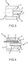
- Proximal member 18further includes at least one fluid or irrigation passageway 24, also referred to as proximal passageway 24, that extends from an inner lumen 26, for example as generally shown in Figures 5-7 , to outer surface 22 of proximal member 18. Inner lumen 26 is in fluid communication with fluid delivery tube 16. As can be further seen in Figures 2-4 , distal member 20 includes a distal passageway 28 that extends to distal end 30 of electrode assembly 10. Fluid passageways 24 of proximal member 18 and distal passageway 28 allow for increased irrigation of electrode assembly 10 during the ablation of tissue. Proximal passageway 24 is separated from and does not come in contact with distal member 20.
- Distal member 20is generally comprised of an electrically, and potentially thermally, conductive material known to those of ordinary skill in the art for delivery of ablative energy to target tissue areas.
- electrically conductive materialinclude gold, platinum, iridium, palladium, stainless steel, and various mixtures and combinations thereof.
- the distal membermay be hemispherical or semispherical in shape, although other configurations may be used.
- Distal member 20may further include an inner cavity 32 for receiving a portion of proximal member 18, as further discussed below.
- Distal member 20further includes an aperture 34 therein forming distal passageway 28.
- Aperture 34extends through distal member 20 to distal end 30 therein providing an opening or outlet for distal passageway 28 on the surface of distal member 20.
- Distal member 20may further be configured with one or more component cavities 36 for receiving and/or housing additional components within distal member 20.
- At least one temperature sensor 38may be provided within a portion (e.g., cavity 36) of distal member 20.
- two temperature sensorsmay be provided within cavities 36 of distal member 20.
- Various configurations of distal member 20may include temperature sensor 38 in different locations and proximities within distal member 20.
- the temperature sensor 38may be either partially or completely surrounded by or encapsulated by an insulation liner 40 that is made of thermally conductive and electrically non-conductive materials.
- Insulation liner 40may be provided in various configurations, such as provided by a tube-like configuration, as shown in Figure 4 .
- Liner 40may be comprised of various materials, such as for example polyimide tubing.
- distal member 20may further include an insulating member 42, i.e. thermal liner, disposed within aperture 34, forming distal passageway 28 of distal member 20.
- Insulating member 42may be comprised of a non and/or poor thermally conductive material.
- Such materialmay include, but is not limited to, high-density polyethylene, polyimides, polyaryletherketones, polyetheretherketones, polyurethane, polypropylene, oriented polypropylene, polyethylene, crystallized polyethylene terephthalate, polyethylene terephthalate, polyester, polyetherimide, acetyl, ceramics, and various combinations thereof.
- Insulating member 42may be generally provided in a configuration that reflects the size and shape of aperture 34, although the insulating member 42 generally extends to meet and connect to inner lumen 26 of proximal member 18. Distal passageway 28 is therein created for the flow of fluid from proximal member 18, for example, as generally shown in Figures 5-7 , through distal passageway 28 to distal end 30 of assembly 10.
- An alternate embodiment of distal member 20includes a cavity 44 for receiving a power wire 46 (see, e.g., Figures 5-7 ) for connecting distal member 20 to an energy source, such as an RF energy source.
- cavity 44may further include a non and/or poor thermally conductive material.
- power wire 46may be soldered directly to distal member 20, or attached and/or connected to distal member 20 through the use of an adhesive or any other connection method known to one of ordinary skill in the art.
- FIGS 5-7generally illustrate alternate embodiments of electrode assembly 10, 10' of the present invention.
- proximal member 18, 18' and distal member 20are configured to be connected and/or coupled together with one another.
- Proximal member 18, 18'is comprised of a thermally nonconductive or reduced (i.e. poor) thermally conductive material that serves to insulate the fluid from the remaining portions of electrode assembly 10, in particular distal member 20.
- proximal member 18, 18'may comprise an electrically nonconductive material.
- overall, proximal member 18, 18'may have lower thermal conductivity than distal member 20.
- proximal member 18, 18'is made from a reduced thermally conductive polymer.
- a reduced thermally conductive materialis one with physical attributes that decrease heat transfer by about 10% or more, provided that the remaining structural components are selected with the appropriate characteristics and sensitivities to maintain adequate monitoring and control of the process.
- One reduced thermally conductive materialmay include polyether ether ketone ("PEEK").
- PEEKpolyether ether ketone
- Further examples of reduced thermally conductive materials useful in conjunction with the present inventioninclude, but are not limited to, high-density polytheylene, polyimides, polyaryletherketones, polyetheretherketones, polyurethane, polypropylene, oriented polypropylene, polyethylene, crystallized polyethylene terephthalate, polyethylene terephthalate, polyester, polyetherimide, acetyl, ceramics, and various combinations thereof.
- proximal member 18is substantially less thermally conductive than distal member 20.
- the irrigation fluid flowing through proximal member 18has very little thermal effect on distal member 20 due to the poor thermal conductivity of proximal member 18 (e.g. less than 5% effect), and preferably nearly 0% effect.
- characteristics and descriptions (e.g. composition and materials) regarding proximal member 18 and 18'may be used interchangeably, among various embodiments except for the specific descriptions provided regarding the design of proximal member 18' in accordance with the embodiment provided in Figure 7 .
- the proximal member 18may further be configured to include a coupling portion 48 that extends into inner cavity 32 of distal member 20.
- Proximal member 18may be generally cylindrical in shape.
- distal member 20 of ablation electrode assembly 10may have a generally cylindrical shape terminating in a hemispherical distal end 30.
- the cylindrical shape of proximal member 18 and distal member 20may be substantially similar to one another and generally have the same overall diameter, which can provide or create a smooth outer body or profile for electrode assembly 10.
- Distal member 20may be configured to accept portion 48 of proximal member 18 for attachment thereto.
- the distal member 20may be connected by any known mechanism including adhesives, press-fit configurations, snap-fit configurations, threaded configurations, or any other mechanism known to one of ordinary skill in the art.
- Proximal member 18may further include an inner lumen 26 that is connected to fluid delivery tube 16.
- the inner lumen 26may act as a manifold or distributor for transporting and/or distributing fluid throughout electrode assembly 10.
- proximal member 18may be configured to receive a fluid delivery tube 16 carried within at least a portion of catheter assembly 12.
- Proximal member 18includes a plurality of passageways 24.
- Proximal member 18may serve as a manifold or distributor of fluid to electrode assembly 10 through the use of passageways 24.
- Proximal passageways 24may extend from inner lumen 26 axially toward outer surface 22 of proximal member 18.
- a plurality of passageways 24are substantially equally distributed around proximal member 18 to provide substantially equal distribution of fluid to the targeted tissue area and/or the outside of electrode assembly 10.
- Electrode assembly 10may be configured to provide a single, annular passageway 24, or a number of individual passageways 24 equally distributed around the proximal member 18.
- the passageways 24may be generally tubular and may have a constant diameter along the length of the passageway. Alternate configurations having various diameters along all or portions of the length of the passageways may be used.
- proximal passageways 24may be directed towards or extend towards distal member 20 of electrode assembly 10 at an angle ( ⁇ ) less than 90 degrees from the central longitudinal axis of proximal member 18. In an embodiment, passageways 24 extends at an angle ( ⁇ ) between about 20 to about 70 degrees, and for some embodiments, between about 30 to about 60 degrees. Alternate positions and angles of the passageway(s) 24 may be provided in alternate embodiments of electrode assembly 10.
- Distal passageway 28is provided for and extends along the central longitudinal axis of proximal member 18 through distal member 20 to distal end 30 of electrode assembly 10. As shown in Figures 5 and 6 , distal passageway 28 may further be fully or partially surrounded by a thermally non-conductive material, such as that provided by insulating member 42. Insulating member 42 prevents saline or any other biocompatible fluid from coming in contact with distal member 20.
- Insulating member 42may be comprised of a thermally non-conductive material such as, but not limited to, high-density polyethylene, polyimides, polyaryletherketones, polyetheretherketones, polyurethane, polypropylene, oriented polypropylene, polyethylene, crystallized polyethylene terephthalate, polyethylene terephthalate, polyester, polyetherimide, acetyl, ceramics, and various combinations thereof.
- a thermally non-conductive materialsuch as, but not limited to, high-density polyethylene, polyimides, polyaryletherketones, polyetheretherketones, polyurethane, polypropylene, oriented polypropylene, polyethylene, crystallized polyethylene terephthalate, polyethylene terephthalate, polyester, polyetherimide, acetyl, ceramics, and various combinations thereof.
- Distal passageway 28extends from inner lumen 26 provided by proximal member 18.
- the diameter of distal passageway 28is less than the diameter of inner lumen 26 of proximal member 18.
- inner lumen 26 and distal passageway 28may be connected by a tapered transition portion 50 therein providing constant fluid communication.
- the angle of the tapered transition portionmay vary depending on the diameters of the inner lumen 26 and distal passageway 28, as well as the length of proximal member 18. The presence of the tapered transition portion 50 between inner lumen 26 and distal passageway 28 prevents air bubbles from being trapped inside the proximal member during fluid flow through the lumen and passageways.
- distal passageway 28is slightly larger in diameter than passageways 24 provided by the proximal member.
- the diameter of passageways 24 and distal passageways 28may vary depending on the configuration and design of electrode assembly 10.
- distal passageway 28includes a diameter within the range of about 0.305 to about 0.381 mm ( about 0.012 to about 0.015 inches), more particularly about 0.330 to about 0.356 mm (about 0.013 to about 0.014 inches) .
- proximal passageways 24include a diameter within in the range of about 0.279 to about 0.356 mm ( about 0.011 to about 0.014 inches), more particularly about 0.279 to about 0.330 mm (about 0.011 to about 0.013 inches).
- the inner surface of inner lumen 26may be either coated with a hydrophilic coating or surface treated to create a hydrophilic surface.
- the treatment of inner lumen 26 with a hypdrophilic surface or coatingresults in another method of preventing air bubbles from becoming trapped inside proximal member 18.
- the hydrophilic coating materialsmay include, but are not limited to, block copolymers based of ethylene oxide and propylene oxide, polymers in the polyethylene glycol family and silicone. For example, those materials selected from the group including PLURONIC ® from BASF, CARBOWAX ® from Dow Chemical Company and SILASTIC MDX ® from Dow Corning.
- Alternate embodiments of the present inventionprovide the incorporation of at least one temperature sensor 38 in combination with distal passageway 28.
- an embodimentas shown in Figure 5 , includes two temperature sensors 38 provided within cavities 36 of distal member 20.
- one temperature sensoris provided within a single cavity 36.
- Temperature sensorsmay include various temperature sensing mechanisms, such as a thermal sensor, disposed therein for measurement and control of electrode assembly 10.
- the temperature sensor 38can be any mechanism known to one of skill in the art, including for example, thermocouples or thermistors.
- the temperature sensor 38may further be surrounded, or encapsulated, by a thermally conductive and electrically non-conductive material, as previously discussed.
- This thermally conductive and electrically non-conductive materialcan serve to hold temperature sensor 38 in place within distal member 20 and provide improved heat exchange between temperature sensor 38 and distal member 20.
- This materialmay be comprised of a number of materials known to one of ordinary skill in the art, including for example, thermally conductive resins, epoxies, or potting compounds.
- proximal member 18'includes proximal end 52 and an extended distal end 54 that is received within aperture 34 of distal member 20 when proximal member 18' and distal member 20 are configured for connection.
- Distal member 20provides a proximal surface 56 and well the surface 60 provided by inner cavity 32 that may be connected to proximal member 18' through the use of bonding or adhesive 58, therein coupling and/or connecting proximal member 18' with distal member 20.
- Inner lumen 26'extends from proximal end 52 to distal end 54 of proximal member 18'. Accordingly proximal member 18 is configured to provide the insulating portion of distal passageway 28 through distal member 20.
- Proximal member 18'further includes proximal passageways 24, as described above that allow fluid flow from inner lumen 26' to outer surface 22' of proximal member 18'. Passageways 24 are directed towards distal member 20 to increase the fluid flow around the intersection of the proximal member to the distal member.
- Figure 7The flow of fluid through inner lumen 26' provided by fluid tube 16 and ultimately through proximal passageways 24 and distal passageway 28 is reflected in Figure 7 .
- Figure 8provides an irrigation flow visualization wherein the fluid from proximal passageways 24 is directed at a 30 degree angle from the central longitudinal axis of proximal member 18, as shown in Figure 7 .
- the flow visualizationfurther shows the flow of fluid out of distal passageway 28, as shown in Figures 5-7 , from distal end 30 of electrode assembly 10'.
- FIG. 9graphically depicts bench test results for ablation electrode assemblies in accordance with an embodiment of the present invention.
- the purpose of the testingwas to confirm that adequate temperature control was being accomplished through the use of the irrigated electrode including a distal passageway as the ablation system was subjected to an overall increase in power (W) (e.g. wattage).
- Woverall increase in power
- the testingwas performed using an embodiment of the present invention wherein ablation was being performed using an electrode assembly that maintained irrigation flow of fluid was 13mL/M at a perpendicular orientation to the muscle tissue being ablated.
- the testingshowed, as reflected in Figure 9 , that an adequate temperature response was exhibited by the ablation electrode assembly, upon the continued increase of power (W) provided to the ablation system.
- the ablation electrodeas provided by the present invention, having a distal irrigation passageway was able to maintain adequate temperature control, for performing ablation, while at the same time sufficiently cooling the electrode tip. Accordingly, it is desirable to provide an irrigated ablation electrode assembly in accordance with the present invention that can achieve adequate temperature response within a desired range for performing ablation procedures.
- the ablation electrode assembly 10, 10' of the present inventionmay comprise part of an irrigated ablation catheter assembly 12, operably connected to a pump assembly and an RF generator assembly which serves to facilitate the operation of ablation procedures through monitoring any number of chosen variables (e.g. temperature of the ablation electrode, ablation energy, and position of the assembly), assist in manipulation of the assembly during use, and provide the requisite energy source delivered to the electrode assembly 10, 10'.
- chosen variablese.g. temperature of the ablation electrode, ablation energy, and position of the assembly
- the present inventionis equally applicable to any number of other ablation electrode assemblies where the temperature of the device and the targeted tissue areas is a factor during the procedure.
- an ablation electrode assembly 10, 10'is provided, having at least one temperature sensor 38 within distal member 20 and proximal member 18 is separate from distal member 20.
- An irrigation pathway 24is provided within the proximal member 18 for delivery of fluid to the outer surface 22 of the proximal member 18.
- a distal passageway 28is further provided for delivery of fluid to the distal end of distal member 20, thereby allowing for the benefits of irrigation of the target site and external portions of electrode assembly 10, such as minimizing tissue damage, such as steam pop, preventing rising impedance of the ablation assembly, and minimizing blood coagulation.
- All directional referencese.g., upper, lower, upward, downward, left, right, leftward, rightward, top, bottom, above, below, vertical, horizontal, clockwise, and counterclockwise
- Joinder referencese.g., attached, coupled, connected, and the like
- Joinder referencesare to be construed broadly and may include intermediate members between a connection of elements and relative movement between elements. As such, joinder references do not necessarily infer that two elements are directly connected and in fixed relation to each other.
Landscapes
- Health & Medical Sciences (AREA)
- Life Sciences & Earth Sciences (AREA)
- Surgery (AREA)
- Engineering & Computer Science (AREA)
- Plasma & Fusion (AREA)
- Medical Informatics (AREA)
- Otolaryngology (AREA)
- Physics & Mathematics (AREA)
- Cardiology (AREA)
- Biomedical Technology (AREA)
- Heart & Thoracic Surgery (AREA)
- Nuclear Medicine, Radiotherapy & Molecular Imaging (AREA)
- Molecular Biology (AREA)
- Animal Behavior & Ethology (AREA)
- General Health & Medical Sciences (AREA)
- Public Health (AREA)
- Veterinary Medicine (AREA)
- Surgical Instruments (AREA)
Description
- The present invention relates to irrigated catheter assemblies. The present invention further relates to ablation electrodes and assemblies, including electrode assemblies having distal irrigation fluid flow. The present invention further relates to ablation electrode assemblies having at least one temperature sensing device and a mechanism for irrigating the ablation assembly and targeted areas.
US 2004/0054272 A1 describes a catheter with an irrigated composite tip electrode. Electrophysiology catheters are used for an ever-growing number of procedures. Catheters are used for diagnostic, therapeutic, and ablative procedures, to name just a few examples. Typically, a catheter is manipulated through the patient's vasculature and to the intended site, for example, a site within the patient's heart. The catheter typically carries one or more electrodes, which may be used for ablation, diagnosis, or other treatments.- There are a number of methods used for ablation of desired areas, including for example, radiofrequency (RF) ablation. Ablation may be facilitated by transmission of energy from an electrode assembly to ablate tissue at the target site. Because ablation may generate significant heat, which if not controlled can result in excessive tissue damage, such as steam pop, tissue charring, and the like, it is desirable to include a mechanism to irrigate the target area and the device with biocompatible fluids, such as water or saline solution. The use of irrigated ablation catheters can also prevent the formation of soft thrombus and/or blood coagulation.
- Typically, there are two classes of irrigated electrode catheters, open and closed irrigation catheters. Closed ablation catheters usually circulate a cooling fluid within the inner cavity or lumen provided by the ablation electrode. Open ablation catheters typically deliver the cooling fluid through open outlets or openings to a surface of the electrode. Open ablation catheters use an inner cavity or lumen of the electrode, as a manifold to distribute saline solution, or other irrigation fluids known to those skilled in the art, to one or more passageways that lead to an opening/outlet provided on the surface of the electrode. The cooling fluid thus flows through the outlets of the passageways onto the electrode member. This flow through the electrode tip lowers the temperature of the tip during operation, often making accurate monitoring and control of the ablative process more difficult.
- In general, open irrigated ablation catheters may improve the function and safety associated with catheter ablation by preventing protein aggregation and blood coagulation. A particular area of the electrode/catheter where the formation of coagulum or thrombus may occur during ablation procedures is at the distal end or tip of the electrode.
- The present description is directed to improved ablation electrode assemblies and methods useful in conjunction with irrigated catheter devices and other ablation catheters. Embodiments of the present invention provide an irrigated catheter having irrigation fluid directed at target areas where coagulation is more likely to occur so as to minimize blood coagulation and associated problems. The present invention includes various embodiments of irrigation electrode assemblies having a passageway for minimizing the blood coagulation and related problems occurring at or about the distal end of the electrode.
- Accordingly, the present invention includes an irrigated ablation electrode assembly. The electrode assembly includes a proximal member having an outer surface and an inner lumen. The electrode assembly further includes a distal member having an outer surface and a distal end. The proximal member and distal member are configured for connection with one another. The assembly further includes at least one proximal passageway extending from the inner lumen to the outer surface of the proximal member. The assembly further includes a distal passageway extending from the inner lumen through the distal member to the distal end of the electrode assembly. In an embodiment, the proximal passageway is separated from and does not come in contact with the distal member.
- The present invention further includes an alternate embodiment of an irrigated ablation electrode assembly. In an alternate embodiment, the electrode assembly includes a proximal member having an outer surface and an inner lumen. The electrode assembly further includes a distal member having an outer surface and a distal end. The proximal member and distal member are configured for connection with one another. The assembly further includes at least one proximal passageway extending from the inner lumen to the outer surface of the proximal member. The assembly further includes a distal passageway extending from the inner lumen through the distal member to the distal end of the electrode assembly. According to the alternate embodiment, the proximal member has a lower thermal conductivity than the distal member.
- The present invention further includes an alternate embodiment of an irrigated ablation electrode assembly. In an alternate embodiment, the electrode assembly includes a proximal member having an outer surface and an inner lumen. The electrode assembly further includes a distal member having an outer surface and a distal end. The proximal member and distal member are configured for connection with one another. The assembly further includes at least one proximal passageway extending from the inner lumen to the outer surface of the proximal member. The assembly further includes a distal passageway extending from the inner lumen through the distal member to the distal end of the electrode assembly. The assembly further includes an insulating member at least partially separating the distal passageway from the distal member, wherein the insulating member has a lower thermal conductivity than the distal member.
- The present invention further includes an alternate embodiment of an irrigated ablation electrode assembly. In an alternate embodiment, the electrode assembly includes a proximal member having an outer surface and an inner lumen. The electrode assembly further includes a distal member having an outer surface and a distal end. The proximal member and distal member are configured for connection with one another. The assembly further includes at least one proximal passageway extending from the inner lumen to the outer surface of the proximal member. The assembly further includes a distal passageway extending from the inner lumen through the distal member to the distal end of the electrode assembly. In accordance with an alternate embodiment, the inner lumen includes a hydrophilic coating.
- The foregoing and other aspects, features, details, utilities, and advantages of the present invention will be apparent from reading the following description and claims, and from reviewing the accompanying drawings.
Figure 1 is an isometric view of an ablation electrode according to an embodiment of the present invention;Figure 2 is an enlarged isometric view of the distal end of the ablation electrode as shown inFigure 1 ;Figure 3 is a side cross-sectional view of a distal member of an ablation electrode according to an alternate embodiment of the present invention;Figure 4 is a side cross-sectional view of a distal member of an ablation electrode according to an alternate embodiment of the present invention;Figures 5-7 are side cross-sectional views of ablation electrodes according to alternate embodiments of the present invention;Figure 8 is an illustrative view of visualized irrigation flow from an ablation electrode according to an alternate embodiment of the present invention; andFigure 9 graphically depicts general bench test results for ablation electrode assemblies in accordance with an embodiment of the present invention.- In general, the instant invention relates to irrigated ablation electrode assemblies, to catheter assemblies, as well as ablation systems employing the irrigated ablation electrode assemblies , 10 and 10', in connection with catheter assemblies. For purposes of this description, similar aspects among the various embodiments described herein will be referred to by the same reference number. As will be appreciated, however, the structure of the various aspects may differ with respect to alternate embodiments.
- As generally shown in the embodiment illustrated in
Figure 1 , theablation electrode assembly 10 may comprise part of an irrigatedablation catheter assembly 12. The embodiments describe RF ablation electrodes and assemblies, but it is contemplated that the present invention is equally applicable to any number of other ablation electrodes and assemblies where the temperature of the device and the targeted tissue area may be factors during the procedure.Figures 3-8 as discussed in more detail below, illustrateablation electrode assemblies 10, 10' according to alternate embodiments of the present invention. - In accordance with an embodiment,
Figure 1 generally illustrates anablation electrode assembly 10 connected tocatheter shaft 14 as part of irrigatedablation catheter assembly 12. Theassembly 12 includes at least onefluid delivery tube 16.Ablation electrode assembly 10 includes aproximal member 18, also referred to as an irrigation member or manifold, and adistal member 20, also referred to as an ablation electrode member.Proximal member 18 anddistal member 20 are configured to be connected together. The orientation ofmembers distal member 20, which provides an ablation electrode or an ablative surface, is situated at the distal end ofassembly 10.Proximal member 18, or irrigation member, is located at the proximal end ofassembly 10, although for some embodiments the orientation could be reversed.Proximal member 18 includes anouter surface 22.Proximal member 18 further includes at least one fluid orirrigation passageway 24, also referred to asproximal passageway 24, that extends from aninner lumen 26, for example as generally shown inFigures 5-7 , toouter surface 22 ofproximal member 18.Inner lumen 26 is in fluid communication withfluid delivery tube 16. As can be further seen inFigures 2-4 ,distal member 20 includes adistal passageway 28 that extends todistal end 30 ofelectrode assembly 10.Fluid passageways 24 ofproximal member 18 anddistal passageway 28 allow for increased irrigation ofelectrode assembly 10 during the ablation of tissue.Proximal passageway 24 is separated from and does not come in contact withdistal member 20. Distal member 20, as shown inFigures 3 and 4 , is generally comprised of an electrically, and potentially thermally, conductive material known to those of ordinary skill in the art for delivery of ablative energy to target tissue areas. Examples of electrically conductive material include gold, platinum, iridium, palladium, stainless steel, and various mixtures and combinations thereof. In an embodiment, the distal member may be hemispherical or semispherical in shape, although other configurations may be used.Distal member 20 may further include aninner cavity 32 for receiving a portion ofproximal member 18, as further discussed below.Distal member 20 further includes anaperture 34 therein formingdistal passageway 28.Aperture 34 extends throughdistal member 20 todistal end 30 therein providing an opening or outlet fordistal passageway 28 on the surface ofdistal member 20.Distal member 20 may further be configured with one ormore component cavities 36 for receiving and/or housing additional components withindistal member 20.- As can be seen in
Figure 4 , at least onetemperature sensor 38, also referred to as a temperature or thermal sensing device, may be provided within a portion (e.g., cavity 36) ofdistal member 20. In an alternate embodiment, two temperature sensors may be provided withincavities 36 ofdistal member 20. Various configurations ofdistal member 20 may includetemperature sensor 38 in different locations and proximities withindistal member 20. In an alternate embodiment, thetemperature sensor 38 may be either partially or completely surrounded by or encapsulated by aninsulation liner 40 that is made of thermally conductive and electrically non-conductive materials.Insulation liner 40 may be provided in various configurations, such as provided by a tube-like configuration, as shown inFigure 4 .Liner 40 may be comprised of various materials, such as for example polyimide tubing. - As generally illustrated in
Figure 4 ,distal member 20, may further include an insulatingmember 42, i.e. thermal liner, disposed withinaperture 34, formingdistal passageway 28 ofdistal member 20. Insulatingmember 42 may be comprised of a non and/or poor thermally conductive material. Such material may include, but is not limited to, high-density polyethylene, polyimides, polyaryletherketones, polyetheretherketones, polyurethane, polypropylene, oriented polypropylene, polyethylene, crystallized polyethylene terephthalate, polyethylene terephthalate, polyester, polyetherimide, acetyl, ceramics, and various combinations thereof. Insulatingmember 42 may be generally provided in a configuration that reflects the size and shape ofaperture 34, although the insulatingmember 42 generally extends to meet and connect toinner lumen 26 ofproximal member 18.Distal passageway 28 is therein created for the flow of fluid fromproximal member 18, for example, as generally shown inFigures 5-7 , throughdistal passageway 28 todistal end 30 ofassembly 10. - An alternate embodiment of
distal member 20 includes acavity 44 for receiving a power wire 46 (see, e.g.,Figures 5-7 ) for connectingdistal member 20 to an energy source, such as an RF energy source. In an alternate embodiment,cavity 44 may further include a non and/or poor thermally conductive material. Furthermore, in an alternate embodiment,power wire 46 may be soldered directly todistal member 20, or attached and/or connected todistal member 20 through the use of an adhesive or any other connection method known to one of ordinary skill in the art. Figures 5-7 generally illustrate alternate embodiments ofelectrode assembly 10, 10' of the present invention. As previously described,proximal member 18, 18' anddistal member 20 are configured to be connected and/or coupled together with one another.Proximal member 18, 18' is comprised of a thermally nonconductive or reduced (i.e. poor) thermally conductive material that serves to insulate the fluid from the remaining portions ofelectrode assembly 10, in particulardistal member 20. Moreover,proximal member 18, 18' may comprise an electrically nonconductive material. Comparatively, overall,proximal member 18, 18' may have lower thermal conductivity thandistal member 20. In an embodiment,proximal member 18, 18' is made from a reduced thermally conductive polymer. A reduced thermally conductive material is one with physical attributes that decrease heat transfer by about 10% or more, provided that the remaining structural components are selected with the appropriate characteristics and sensitivities to maintain adequate monitoring and control of the process. One reduced thermally conductive material may include polyether ether ketone ("PEEK"). Further examples of reduced thermally conductive materials useful in conjunction with the present invention include, but are not limited to, high-density polytheylene, polyimides, polyaryletherketones, polyetheretherketones, polyurethane, polypropylene, oriented polypropylene, polyethylene, crystallized polyethylene terephthalate, polyethylene terephthalate, polyester, polyetherimide, acetyl, ceramics, and various combinations thereof. Moreover,proximal member 18 is substantially less thermally conductive thandistal member 20. As a result, the irrigation fluid flowing throughproximal member 18 has very little thermal effect ondistal member 20 due to the poor thermal conductivity of proximal member 18 (e.g. less than 5% effect), and preferably nearly 0% effect. In general, characteristics and descriptions (e.g. composition and materials) regardingproximal member 18 and 18' may be used interchangeably, among various embodiments except for the specific descriptions provided regarding the design of proximal member 18' in accordance with the embodiment provided inFigure 7 .- The
proximal member 18 may further be configured to include acoupling portion 48 that extends intoinner cavity 32 ofdistal member 20.Proximal member 18 may be generally cylindrical in shape. Moreover, for some embodiments,distal member 20 ofablation electrode assembly 10 may have a generally cylindrical shape terminating in a hemisphericaldistal end 30. The cylindrical shape ofproximal member 18 anddistal member 20 may be substantially similar to one another and generally have the same overall diameter, which can provide or create a smooth outer body or profile forelectrode assembly 10.Distal member 20 may be configured to acceptportion 48 ofproximal member 18 for attachment thereto. Thedistal member 20 may be connected by any known mechanism including adhesives, press-fit configurations, snap-fit configurations, threaded configurations, or any other mechanism known to one of ordinary skill in the art. Proximal member 18 may further include aninner lumen 26 that is connected tofluid delivery tube 16. Theinner lumen 26 may act as a manifold or distributor for transporting and/or distributing fluid throughoutelectrode assembly 10. In particular,proximal member 18 may be configured to receive afluid delivery tube 16 carried within at least a portion ofcatheter assembly 12.Proximal member 18 includes a plurality ofpassageways 24.Proximal member 18 may serve as a manifold or distributor of fluid toelectrode assembly 10 through the use ofpassageways 24.Proximal passageways 24 may extend frominner lumen 26 axially towardouter surface 22 ofproximal member 18. In an embodiment, a plurality ofpassageways 24 are substantially equally distributed aroundproximal member 18 to provide substantially equal distribution of fluid to the targeted tissue area and/or the outside ofelectrode assembly 10.Electrode assembly 10 may be configured to provide a single,annular passageway 24, or a number ofindividual passageways 24 equally distributed around theproximal member 18. Moreover, thepassageways 24 may be generally tubular and may have a constant diameter along the length of the passageway. Alternate configurations having various diameters along all or portions of the length of the passageways may be used.- As shown in
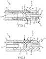
Figures 5-7 ,proximal passageways 24 may be directed towards or extend towardsdistal member 20 ofelectrode assembly 10 at an angle (Θ) less than 90 degrees from the central longitudinal axis ofproximal member 18. In an embodiment, passageways 24 extends at an angle (Θ) between about 20 to about 70 degrees, and for some embodiments, between about 30 to about 60 degrees. Alternate positions and angles of the passageway(s) 24 may be provided in alternate embodiments ofelectrode assembly 10. Distal passageway 28 is provided for and extends along the central longitudinal axis ofproximal member 18 throughdistal member 20 todistal end 30 ofelectrode assembly 10. As shown inFigures 5 and 6 ,distal passageway 28 may further be fully or partially surrounded by a thermally non-conductive material, such as that provided by insulatingmember 42. Insulatingmember 42 prevents saline or any other biocompatible fluid from coming in contact withdistal member 20. Insulatingmember 42 may be comprised of a thermally non-conductive material such as, but not limited to, high-density polyethylene, polyimides, polyaryletherketones, polyetheretherketones, polyurethane, polypropylene, oriented polypropylene, polyethylene, crystallized polyethylene terephthalate, polyethylene terephthalate, polyester, polyetherimide, acetyl, ceramics, and various combinations thereof.Distal passageway 28 extends frominner lumen 26 provided byproximal member 18. In general, the diameter ofdistal passageway 28 is less than the diameter ofinner lumen 26 ofproximal member 18. Accordingly, in one embodiment,inner lumen 26 anddistal passageway 28 may be connected by a taperedtransition portion 50 therein providing constant fluid communication. The angle of the tapered transition portion may vary depending on the diameters of theinner lumen 26 anddistal passageway 28, as well as the length ofproximal member 18. The presence of the taperedtransition portion 50 betweeninner lumen 26 anddistal passageway 28 prevents air bubbles from being trapped inside the proximal member during fluid flow through the lumen and passageways. In an embodiment,distal passageway 28 is slightly larger in diameter thanpassageways 24 provided by the proximal member. The diameter ofpassageways 24 anddistal passageways 28 may vary depending on the configuration and design ofelectrode assembly 10. In an embodiment,distal passageway 28 includes a diameter within the range of about 0.305 to about 0.381 mm ( about 0.012 to about 0.015 inches), more particularly about 0.330 to about 0.356 mm (about 0.013 to about 0.014 inches) . In another embodiment,proximal passageways 24 include a diameter within in the range of about 0.279 to about 0.356 mm ( about 0.011 to about 0.014 inches), more particularly about 0.279 to about 0.330 mm (about 0.011 to about 0.013 inches).- In another embodiment, the inner surface of
inner lumen 26 may be either coated with a hydrophilic coating or surface treated to create a hydrophilic surface. The treatment ofinner lumen 26 with a hypdrophilic surface or coating results in another method of preventing air bubbles from becoming trapped insideproximal member 18. The hydrophilic coating materials may include, but are not limited to, block copolymers based of ethylene oxide and propylene oxide, polymers in the polyethylene glycol family and silicone. For example, those materials selected from the group including PLURONIC® from BASF, CARBOWAX® from Dow Chemical Company and SILASTIC MDX® from Dow Corning. - Alternate embodiments of the present invention provide the incorporation of at least one
temperature sensor 38 in combination withdistal passageway 28. In particular, an embodiment, as shown inFigure 5 , includes twotemperature sensors 38 provided withincavities 36 ofdistal member 20. In an alternate embodiment, as shown inFigure 6 , one temperature sensor is provided within asingle cavity 36. Temperature sensors may include various temperature sensing mechanisms, such as a thermal sensor, disposed therein for measurement and control ofelectrode assembly 10. Thetemperature sensor 38 can be any mechanism known to one of skill in the art, including for example, thermocouples or thermistors. Thetemperature sensor 38 may further be surrounded, or encapsulated, by a thermally conductive and electrically non-conductive material, as previously discussed. This thermally conductive and electrically non-conductive material can serve to holdtemperature sensor 38 in place withindistal member 20 and provide improved heat exchange betweentemperature sensor 38 anddistal member 20. This material may be comprised of a number of materials known to one of ordinary skill in the art, including for example, thermally conductive resins, epoxies, or potting compounds. - In another embodiment of
electrode assembly 10, as seen inFigure 7 , proximal member 18' includesproximal end 52 and an extendeddistal end 54 that is received withinaperture 34 ofdistal member 20 when proximal member 18' anddistal member 20 are configured for connection.Distal member 20 provides aproximal surface 56 and well thesurface 60 provided byinner cavity 32 that may be connected to proximal member 18' through the use of bonding or adhesive 58, therein coupling and/or connecting proximal member 18' withdistal member 20. Inner lumen 26' extends fromproximal end 52 todistal end 54 of proximal member 18'. Accordinglyproximal member 18 is configured to provide the insulating portion ofdistal passageway 28 throughdistal member 20. As a result, the non-thermally conductive material of the proximal member, as previously described above, insulatesdistal passageway 28 throughdistal member 20. Proximal member 18' further includesproximal passageways 24, as described above that allow fluid flow from inner lumen 26' to outer surface 22' of proximal member 18'.Passageways 24 are directed towardsdistal member 20 to increase the fluid flow around the intersection of the proximal member to the distal member. - The flow of fluid through inner lumen 26' provided by
fluid tube 16 and ultimately throughproximal passageways 24 anddistal passageway 28 is reflected inFigure 7 . In particular,Figure 8 provides an irrigation flow visualization wherein the fluid fromproximal passageways 24 is directed at a 30 degree angle from the central longitudinal axis ofproximal member 18, as shown inFigure 7 . The flow visualization further shows the flow of fluid out ofdistal passageway 28, as shown inFigures 5-7 , fromdistal end 30 of electrode assembly 10'. Figure 9 graphically depicts bench test results for ablation electrode assemblies in accordance with an embodiment of the present invention. The purpose of the testing was to confirm that adequate temperature control was being accomplished through the use of the irrigated electrode including a distal passageway as the ablation system was subjected to an overall increase in power (W) (e.g. wattage). Overall, the testing was performed using an embodiment of the present invention wherein ablation was being performed using an electrode assembly that maintained irrigation flow of fluid was 13mL/M at a perpendicular orientation to the muscle tissue being ablated. The testing showed, as reflected inFigure 9 , that an adequate temperature response was exhibited by the ablation electrode assembly, upon the continued increase of power (W) provided to the ablation system. Overall, the ablation electrode, as provided by the present invention, having a distal irrigation passageway was able to maintain adequate temperature control, for performing ablation, while at the same time sufficiently cooling the electrode tip. Accordingly, it is desirable to provide an irrigated ablation electrode assembly in accordance with the present invention that can achieve adequate temperature response within a desired range for performing ablation procedures.- As previously discussed, the
ablation electrode assembly 10, 10' of the present invention may comprise part of an irrigatedablation catheter assembly 12, operably connected to a pump assembly and an RF generator assembly which serves to facilitate the operation of ablation procedures through monitoring any number of chosen variables (e.g. temperature of the ablation electrode, ablation energy, and position of the assembly), assist in manipulation of the assembly during use, and provide the requisite energy source delivered to theelectrode assembly 10, 10'. Although the present embodiments describe RF ablation electrode assemblies and methods, it is contemplated that the present invention is equally applicable to any number of other ablation electrode assemblies where the temperature of the device and the targeted tissue areas is a factor during the procedure. - In addition to the preferred embodiments discussed above, the present invention contemplates methods for improved measure and control of a temperature of an irrigated
ablation electrode assembly 10, 10' or a target site and minimization of coagulation and excess tissue damage at and around the target site. According to one method, anablation electrode assembly 10, 10' is provided, having at least onetemperature sensor 38 withindistal member 20 andproximal member 18 is separate fromdistal member 20. Anirrigation pathway 24 is provided within theproximal member 18 for delivery of fluid to theouter surface 22 of theproximal member 18. Adistal passageway 28 is further provided for delivery of fluid to the distal end ofdistal member 20, thereby allowing for the benefits of irrigation of the target site and external portions ofelectrode assembly 10, such as minimizing tissue damage, such as steam pop, preventing rising impedance of the ablation assembly, and minimizing blood coagulation. - Other embodiments and uses of the devices and methods of the present description will be apparent to those skilled in the art from consideration of the specification and practice of the invention disclosed herein. The specification and examples should be considered exemplary only with the true scope of the invention indicated by the following claims. Although a number of embodiments of this invention have been described above with a certain degree of particularity, those skilled in the art could make numerous alterations to the disclosed embodiments without departing from the scope of this invention.
- All directional references (e.g., upper, lower, upward, downward, left, right, leftward, rightward, top, bottom, above, below, vertical, horizontal, clockwise, and counterclockwise) are only used for identification purposes to aid the reader's understanding of the present invention, and do not create limitations, particularly as to the position, orientation, or use of the invention. Joinder references (e.g., attached, coupled, connected, and the like) are to be construed broadly and may include intermediate members between a connection of elements and relative movement between elements. As such, joinder references do not necessarily infer that two elements are directly connected and in fixed relation to each other.
Claims (9)
- An irrigated ablation electrode assembly (10, 10') comprising:a proximal member (18, 18') having an outer surface (22), an inner lumen (26, 26') and a proximal passageway (24) extending from the inner lumen (26, 26') to the outer surface (22) of the proximal member (18, 18'), the inner lumen including a hydrophilic coating; anda distal member (20) having an outer surface, a distal end (30), and a distal passageway (28) extending from the inner lumen (26, 26') through the distal member (20) to the distal end (30);wherein the proximal member (18, 18') and distal member (20) are configured for connection with one another.
- The electrode assembly (10, 10') of claim 1, including a temperature sensor (38) in the distal member (20).
- The electrode assembly (10, 10') of claim 2, wherein at least a portion of the temperature sensor (38) is surrounded by an electrically nonconductive material.
- The electrode assembly (10, 10') of any one of the preceding claims, wherein the proximal member (18, 18') is comprised of an electrically nonconductive material and the distal member (20) is comprised of an electrically conductive material.
- The electrode assembly (10) of any one of the preceding claims, wherein at least a portion of the distal passageway (28) is thermally insulated from the distal member (20) by a thermally nonconductive material.
- The electrode assembly (10, 10') of any one of the preceding claims, wherein the distal passageway (28) extends axially along a central longitudinal axis of the proximal member (18, 18') towards the distal member (20).
- The electrode assembly (10, 10') of any one of the preceding claims, wherein the proximal passageway (24) extends towards the distal member (20) at an angle less than perpendicular to a central longitudinal axis of the proximal member (18, 18').
- The electrode assembly (10, 10') of any one of the preceding claims, wherein the diameter of the inner lumen (26, 26') is greater than the diameter of the distal passageway (28) and are connected together by a tapered transition portion (50) of the inner lumen (26, 26').
- An irrigated ablation catheter comprising:an irrigated ablation electrode assembly (10, 10') according to any one of the preceding claims; anda catheter shaft (14) having a distal end;wherein the proximal member (18, 18') is connected to the distal end of the catheter shaft (14);the distal member (20) is connected to the proximal member (18, 18'); andthe distal member (20) comprises an electrode.
Applications Claiming Priority (2)
| Application Number | Priority Date | Filing Date | Title |
|---|---|---|---|
| US82895506P | 2006-10-10 | 2006-10-10 | |
| PCT/US2007/080920WO2008045925A2 (en) | 2006-10-10 | 2007-10-10 | Ablation electrode assembly with insulated distal outlet |
Publications (3)
| Publication Number | Publication Date |
|---|---|
| EP2066251A2 EP2066251A2 (en) | 2009-06-10 |
| EP2066251A4 EP2066251A4 (en) | 2010-12-08 |
| EP2066251B1true EP2066251B1 (en) | 2017-05-03 |
Family
ID=39283584
Family Applications (1)
| Application Number | Title | Priority Date | Filing Date |
|---|---|---|---|
| EP07853905.3AActiveEP2066251B1 (en) | 2006-10-10 | 2007-10-10 | Ablation electrode assembly with insulated distal outlet |
Country Status (4)
| Country | Link |
|---|---|
| US (5) | US8551085B2 (en) |
| EP (1) | EP2066251B1 (en) |
| JP (1) | JP5192489B2 (en) |
| WO (1) | WO2008045925A2 (en) |
Families Citing this family (55)
| Publication number | Priority date | Publication date | Assignee | Title |
|---|---|---|---|---|
| US20080091193A1 (en) | 2005-05-16 | 2008-04-17 | James Kauphusman | Irrigated ablation catheter having magnetic tip for magnetic field control and guidance |
| US8128621B2 (en)* | 2005-05-16 | 2012-03-06 | St. Jude Medical, Atrial Fibrillation Division, Inc. | Irrigated ablation electrode assembly and method for control of temperature |
| WO2008045925A2 (en) | 2006-10-10 | 2008-04-17 | St. Jude Medical, Atrial Fibrillation Division, Inc. | Ablation electrode assembly with insulated distal outlet |
| KR101108569B1 (en)* | 2008-05-15 | 2012-01-30 | 전명기 | Electrode for high frequency electrosurgery that coagulates necrosis of living tissue |
| US8974453B2 (en) | 2008-12-02 | 2015-03-10 | St. Jude Medical, Atrial Fibrillation Division, Inc. | Irrigated ablation catheter having a flexible manifold |
| US10105177B2 (en) | 2008-12-31 | 2018-10-23 | St. Jude Medical, Atrial Fibrillation Division, Inc. | Irrigated ablation electrode assembly having off-center irrigation passageway |
| US9226791B2 (en) | 2012-03-12 | 2016-01-05 | Advanced Cardiac Therapeutics, Inc. | Systems for temperature-controlled ablation using radiometric feedback |
| US8926605B2 (en) | 2012-02-07 | 2015-01-06 | Advanced Cardiac Therapeutics, Inc. | Systems and methods for radiometrically measuring temperature during tissue ablation |
| US9277961B2 (en) | 2009-06-12 | 2016-03-08 | Advanced Cardiac Therapeutics, Inc. | Systems and methods of radiometrically determining a hot-spot temperature of tissue being treated |
| US8954161B2 (en) | 2012-06-01 | 2015-02-10 | Advanced Cardiac Therapeutics, Inc. | Systems and methods for radiometrically measuring temperature and detecting tissue contact prior to and during tissue ablation |
| EP2453821A1 (en)* | 2009-07-13 | 2012-05-23 | Boston Scientific Scimed, Inc. | Open-irrigated ablation catheter with turbulent flow |
| US9616199B2 (en)* | 2009-12-31 | 2017-04-11 | St. Jude Medical, Atrial Fibrillation Division, Inc. | Irrigated catheter employing multi-lumenal irrigation tubing |
| US10369327B2 (en)* | 2010-04-28 | 2019-08-06 | Clph, Llc | Catheters with lubricious linings and methods for making and using them |
| US9023033B2 (en) | 2010-08-04 | 2015-05-05 | St. Jude Medical, Atrial Fibrillation Division, Inc. | Magnetically guided catheters |
| US9788891B2 (en) | 2010-12-28 | 2017-10-17 | St. Jude Medical, Atrial Fibrillation Division, Inc. | Ablation electrode assemblies and methods for using same |
| US9855094B2 (en) | 2010-12-28 | 2018-01-02 | St. Jude Medical, Atrial Fibrillation Division, Inc. | Multi-rate fluid flow and variable power delivery for ablation electrode assemblies used in catheter ablation procedures |
| US8814857B2 (en) | 2010-12-17 | 2014-08-26 | St. Jude Medical, Atrial Filbrillation Division, Inc. | Irrigated ablation electrode assemblies |
| US8979840B2 (en) | 2010-12-17 | 2015-03-17 | St. Jude Medical, Atrial Fibrillation Division, Inc. | Irrigant distribution system for flexible electrodes |
| ES2864589T3 (en) | 2011-04-12 | 2021-10-14 | Thermedical Inc | Devices for conformal therapy in fluid-enhanced ablation |
| JP5731668B2 (en)* | 2011-06-16 | 2015-06-10 | セント・ジュード・メディカル・エイトリアル・フィブリレーション・ディヴィジョン・インコーポレーテッド | Irrigation solution dispersion system for flexible electrodes |
| DE102011082307A1 (en)* | 2011-09-07 | 2013-03-07 | Celon Ag Medical Instruments | Electrosurgical instrument, electrosurgical device and related methods |
| JP5881229B2 (en)* | 2011-12-09 | 2016-03-09 | 日本ライフライン株式会社 | Electrode catheter |
| CN103315808A (en)* | 2012-03-23 | 2013-09-25 | 心诺普医疗技术(北京)有限公司 | Ablation electrode and injection type electrode conduit adopting same |
| US20130274737A1 (en)* | 2012-04-16 | 2013-10-17 | Boston Scientific Scimed, Inc. | Renal nerve modulation catheter design |
| JP5348675B1 (en)* | 2012-05-30 | 2013-11-20 | 日本ライフライン株式会社 | Electrode catheter |
| CN103800072B (en)* | 2012-11-09 | 2016-04-13 | 上海微创电生理医疗科技有限公司 | Termination electrode and the assembly method with electrophysiologicalcatheter catheter thereof |
| US9066725B2 (en) | 2012-12-06 | 2015-06-30 | St. Jude Medical, Atrial Fibrillation Division, Inc. | Irrigant distribution system for electrodes |
| US9445725B2 (en)* | 2012-12-17 | 2016-09-20 | Biosense Webster (Israel) Ltd. | Irrigated catheter tip with temperature sensor array |
| WO2014151822A2 (en) | 2013-03-15 | 2014-09-25 | Boston Scientific Scimed, Inc. | Open irrigated ablation catheter |
| EP2967731B1 (en) | 2013-03-15 | 2020-10-07 | Boston Scientific Scimed, Inc. | Open irrigated ablation catheter with proximal cooling |
| EP3417821B1 (en) | 2013-10-28 | 2021-06-30 | St. Jude Medical, Cardiology Division, Inc. | Ablation catheter designs with enhanced diagnostic capabilities |
| WO2016081611A1 (en) | 2014-11-19 | 2016-05-26 | Advanced Cardiac Therapeutics, Inc. | High-resolution mapping of tissue with pacing |
| JP6825789B2 (en) | 2014-11-19 | 2021-02-03 | エピックス セラピューティクス,インコーポレイテッド | Systems and methods for high resolution mapping of tissues |
| JP6725178B2 (en) | 2014-11-19 | 2020-07-15 | エピックス セラピューティクス,インコーポレイテッド | Ablation apparatus, systems and methods using high resolution electrode assemblies |
| US9636164B2 (en) | 2015-03-25 | 2017-05-02 | Advanced Cardiac Therapeutics, Inc. | Contact sensing systems and methods |
| EP3777745B1 (en) | 2015-03-31 | 2024-06-05 | St. Jude Medical, Cardiology Division, Inc. | Device for delivering pulsed rf energy during catheter ablation |
| CN104825226A (en)* | 2015-05-04 | 2015-08-12 | 中国人民解放军总医院 | Large ablation head and ablation device |
| JP6933857B2 (en)* | 2015-10-29 | 2021-09-08 | イノブレイティブ デザインズ, インコーポレイテッド | Net spherical tissue ablation device and method |
| US12207863B2 (en) | 2015-10-29 | 2025-01-28 | Innoblative Designs, Inc. | Screen sphere tissue ablation devices and methods |
| WO2017160808A1 (en) | 2016-03-15 | 2017-09-21 | Advanced Cardiac Therapeutics, Inc. | Improved devices, systems and methods for irrigated ablation |
| US9743984B1 (en)* | 2016-08-11 | 2017-08-29 | Thermedical, Inc. | Devices and methods for delivering fluid to tissue during ablation therapy |
| CN106362296A (en)* | 2016-08-26 | 2017-02-01 | 詹佳境 | Radio frequency physiotherapy instrument for gynecological department |
| JP6718557B2 (en) | 2016-10-04 | 2020-07-08 | セント・ジュード・メディカル,カーディオロジー・ディヴィジョン,インコーポレイテッド | Ablation catheter tip |
| EP3522807B1 (en) | 2016-10-04 | 2025-07-09 | Avent, Inc. | Cooled rf probes |
| WO2018075389A1 (en) | 2016-10-17 | 2018-04-26 | Innoblative Designs, Inc. | Treatment devices and methods |
| JP6875757B2 (en) | 2016-11-08 | 2021-05-26 | イノブレイティブ デザインズ, インコーポレイテッド | Electrosurgical tissue and vascular seal device |
| CN110809448B (en) | 2017-04-27 | 2022-11-25 | Epix疗法公司 | Determining properties of contact between catheter tip and tissue |
| EP3658053B1 (en) | 2017-07-26 | 2023-09-13 | Innoblative Designs, Inc. | Minimally invasive articulating assembly having ablation capabilities |
| US11918277B2 (en) | 2018-07-16 | 2024-03-05 | Thermedical, Inc. | Inferred maximum temperature monitoring for irrigated ablation therapy |
| WO2020198150A2 (en) | 2019-03-22 | 2020-10-01 | Stryker Corporation | Systems for ablating tissue |
| EP3972510A1 (en) | 2019-08-29 | 2022-03-30 | St. Jude Medical, Cardiology Division, Inc. | Force sensing catheter including sealed electrode tip assembly and methods of assembling same |
| WO2022201340A1 (en)* | 2021-03-24 | 2022-09-29 | 日本ライフライン株式会社 | Electrode catheter |
| US20220395322A1 (en)* | 2021-06-15 | 2022-12-15 | Biosense Webster (Israel) Ltd. | Catheter for high-power focal ablation |
| JP7727324B2 (en)* | 2022-10-31 | 2025-08-21 | 株式会社タスク | syringe needle |
| CN120676915A (en) | 2022-12-28 | 2025-09-19 | 阿特拉弗斯医疗股份有限公司 | Methods, systems and devices for perforating tissue structures |
Citations (2)
| Publication number | Priority date | Publication date | Assignee | Title |
|---|---|---|---|---|
| JPH0994296A (en)* | 1995-09-28 | 1997-04-08 | Terumo Corp | Catheter |
| WO1999056812A2 (en)* | 1998-05-06 | 1999-11-11 | Atrionix, Inc. | Irrigated ablation device assembly |
Family Cites Families (52)
| Publication number | Priority date | Publication date | Assignee | Title |
|---|---|---|---|---|
| US785810A (en)* | 1904-07-19 | 1905-03-28 | Peter Koopman | Ladder. |
| US5421819A (en)* | 1992-08-12 | 1995-06-06 | Vidamed, Inc. | Medical probe device |
| US5542915A (en)* | 1992-08-12 | 1996-08-06 | Vidamed, Inc. | Thermal mapping catheter with ultrasound probe |
| US4682596A (en)* | 1984-05-22 | 1987-07-28 | Cordis Corporation | Electrosurgical catheter and method for vascular applications |
| US4904238A (en)* | 1987-12-21 | 1990-02-27 | Alcon Laboratories, Inc. | Irrigation/aspiration handpiece |
| US5230349A (en)* | 1988-11-25 | 1993-07-27 | Sensor Electronics, Inc. | Electrical heating catheter |
| US5056517A (en)* | 1989-07-24 | 1991-10-15 | Consiglio Nazionale Delle Ricerche | Biomagnetically localizable multipurpose catheter and method for magnetocardiographic guided intracardiac mapping, biopsy and ablation of cardiac arrhythmias |
| US5409453A (en)* | 1992-08-12 | 1995-04-25 | Vidamed, Inc. | Steerable medical probe with stylets |
| DE4338758C2 (en)* | 1992-11-13 | 2001-08-09 | Scimed Life Systems Inc | Catheter assembly |
| US5676693A (en)* | 1992-11-13 | 1997-10-14 | Scimed Life Systems, Inc. | Electrophysiology device |
| US5348554A (en)* | 1992-12-01 | 1994-09-20 | Cardiac Pathways Corporation | Catheter for RF ablation with cooled electrode |
| US5545161A (en)* | 1992-12-01 | 1996-08-13 | Cardiac Pathways Corporation | Catheter for RF ablation having cooled electrode with electrically insulated sleeve |
| US5706809A (en)* | 1993-01-29 | 1998-01-13 | Cardima, Inc. | Method and system for using multiple intravascular sensing devices to detect electrical activity |
| US5403311A (en)* | 1993-03-29 | 1995-04-04 | Boston Scientific Corporation | Electro-coagulation and ablation and other electrotherapeutic treatments of body tissue |
| US5431168A (en)* | 1993-08-23 | 1995-07-11 | Cordis-Webster, Inc. | Steerable open-lumen catheter |
| US5462521A (en)* | 1993-12-21 | 1995-10-31 | Angeion Corporation | Fluid cooled and perfused tip for a catheter |
| US5814029A (en)* | 1994-11-03 | 1998-09-29 | Daig Corporation | Guiding introducer system for use in ablation and mapping procedures in the left ventricle |
| US5897553A (en)* | 1995-11-02 | 1999-04-27 | Medtronic, Inc. | Ball point fluid-assisted electrocautery device |
| US6363937B1 (en)* | 1995-06-07 | 2002-04-02 | Arthrocare Corporation | System and methods for electrosurgical treatment of the digestive system |
| US5919188A (en)* | 1997-02-04 | 1999-07-06 | Medtronic, Inc. | Linear ablation catheter |
| US5792140A (en)* | 1997-05-15 | 1998-08-11 | Irvine Biomedical, Inc. | Catheter having cooled multiple-needle electrode |
| US5913856A (en)* | 1997-05-19 | 1999-06-22 | Irvine Biomedical, Inc. | Catheter system having a porous shaft and fluid irrigation capabilities |
| US5843152A (en)* | 1997-06-02 | 1998-12-01 | Irvine Biomedical, Inc. | Catheter system having a ball electrode |
| US6217576B1 (en)* | 1997-05-19 | 2001-04-17 | Irvine Biomedical Inc. | Catheter probe for treating focal atrial fibrillation in pulmonary veins |
| US6869431B2 (en)* | 1997-07-08 | 2005-03-22 | Atrionix, Inc. | Medical device with sensor cooperating with expandable member |
| US6162219A (en)* | 1997-10-21 | 2000-12-19 | Akzo Nobel N.V. | Electrode |
| US6120476A (en)* | 1997-12-01 | 2000-09-19 | Cordis Webster, Inc. | Irrigated tip catheter |
| US6238393B1 (en)* | 1998-07-07 | 2001-05-29 | Medtronic, Inc. | Method and apparatus for creating a bi-polar virtual electrode used for the ablation of tissue |
| US7485092B1 (en)* | 1998-08-12 | 2009-02-03 | Maquet Cardiovascular Llc | Vessel harvesting apparatus and method |
| US6171275B1 (en)* | 1998-12-03 | 2001-01-09 | Cordis Webster, Inc. | Irrigated split tip electrode catheter |
| US5971968A (en)* | 1999-04-08 | 1999-10-26 | Irvine Biomedical, Inc. | Catheter probe having contrast media delivery means |
| EP1179995B1 (en) | 1999-05-11 | 2007-01-31 | Atrionix, Inc. | Balloon anchor wire |
| US6383144B1 (en)* | 2000-01-18 | 2002-05-07 | Edwards Lifesciences Corporation | Devices and methods for measuring temperature of a patient |
| GB2372500B (en) | 2001-02-22 | 2003-08-20 | Reckitt Benckiser Nv | Process for Inhibition of Corrosion of Glassware during Automatic Dishwashing |
| US7160296B2 (en)* | 2001-05-10 | 2007-01-09 | Rita Medical Systems, Inc. | Tissue ablation apparatus and method |
| US20020198520A1 (en)* | 2001-06-20 | 2002-12-26 | Scimed Life Systems, Inc. | Irrigation sheath |
| US6611699B2 (en)* | 2001-06-28 | 2003-08-26 | Scimed Life Systems, Inc. | Catheter with an irrigated composite tip electrode |
| DE10248377A1 (en)* | 2002-10-17 | 2004-05-06 | Haindl, Hans, Dr.med. | Cannula, in particular for spinal anesthesia, and method for the production thereof |
| WO2004098382A2 (en)* | 2003-05-01 | 2004-11-18 | Sherwood Services Ag | Suction coagulator with dissecting probe |
| DE10342709A1 (en)* | 2003-09-11 | 2005-04-21 | Biotronik Gmbh & Co Kg | catheter |
| US7207989B2 (en)* | 2003-10-27 | 2007-04-24 | Biosense Webster, Inc. | Method for ablating with needle electrode |
| NL1024658C2 (en)* | 2003-10-29 | 2005-05-02 | Univ Medisch Centrum Utrecht | Catheter and method, in particular for ablation and the like. |
| EP1761187B1 (en) | 2004-05-17 | 2011-11-30 | C.R. Bard, Inc. | Irrigated catheter |
| JP5058813B2 (en)* | 2004-11-15 | 2012-10-24 | バイオセンス・ウエブスター・インコーポレーテツド | Catheter with multiple microfabricated temperature sensors |
| CA2587619C (en)* | 2004-11-15 | 2017-02-28 | Biosense Webster, Inc. | Catheter with micro-fabricated temperature sensing |
| US7918851B2 (en)* | 2005-02-14 | 2011-04-05 | Biosense Webster, Inc. | Irrigated tip catheter and method for manufacturing therefor |
| US7857810B2 (en)* | 2006-05-16 | 2010-12-28 | St. Jude Medical, Atrial Fibrillation Division, Inc. | Ablation electrode assembly and methods for improved control of temperature and minimization of coagulation and tissue damage |
| US7628788B2 (en)* | 2005-12-30 | 2009-12-08 | Biosense Webster, Inc. | Ablation catheter with improved tip cooling |
| US7879029B2 (en)* | 2005-12-30 | 2011-02-01 | Biosense Webster, Inc. | System and method for selectively energizing catheter electrodes |
| US8486127B2 (en)* | 2006-05-24 | 2013-07-16 | Kambiz Dowlatshahi | High temperature thermal therapy of breast cancer |
| WO2008045925A2 (en) | 2006-10-10 | 2008-04-17 | St. Jude Medical, Atrial Fibrillation Division, Inc. | Ablation electrode assembly with insulated distal outlet |
| WO2009048824A1 (en)* | 2007-10-09 | 2009-04-16 | Boston Scientific Scimed, Inc. | Electrophysiology electrodes and apparatus including the same |
- 2007
- 2007-10-10WOPCT/US2007/080920patent/WO2008045925A2/enactiveApplication Filing
- 2007-10-10EPEP07853905.3Apatent/EP2066251B1/enactiveActive
- 2007-10-10USUS12/440,866patent/US8551085B2/enactiveActive
- 2007-10-10JPJP2009532551Apatent/JP5192489B2/enactiveActive
- 2008
- 2008-12-30USUS12/346,634patent/US10130418B2/enactiveActive
- 2018
- 2018-11-19USUS16/195,575patent/US11096742B2/enactiveActive
- 2021
- 2021-07-19USUS17/379,801patent/US11871986B2/enactiveActive
- 2023
- 2023-12-08USUS18/534,123patent/US20240173073A1/enactivePending
Patent Citations (2)
| Publication number | Priority date | Publication date | Assignee | Title |
|---|---|---|---|---|
| JPH0994296A (en)* | 1995-09-28 | 1997-04-08 | Terumo Corp | Catheter |
| WO1999056812A2 (en)* | 1998-05-06 | 1999-11-11 | Atrionix, Inc. | Irrigated ablation device assembly |
Non-Patent Citations (1)
| Title |
|---|
| SMITH ET AL: "The hydrophilic nature of a clean gold surface", JOURNAL OF COLLOID AND INTERFACE SCIENCE, ACADEMIC PRESS, NEW YORK, NY, US, vol. 75, no. 1, 1 May 1980 (1980-05-01), pages 51 - 55, XP024189742, ISSN: 0021-9797, [retrieved on 19800501], DOI: 10.1016/0021-9797(80)90348-3* |
Also Published As
| Publication number | Publication date |
|---|---|
| JP2010505596A (en) | 2010-02-25 |
| US11871986B2 (en) | 2024-01-16 |
| EP2066251A2 (en) | 2009-06-10 |
| JP5192489B2 (en) | 2013-05-08 |
| US20240173073A1 (en) | 2024-05-30 |
| US20220000549A1 (en) | 2022-01-06 |
| US8551085B2 (en) | 2013-10-08 |
| US10130418B2 (en) | 2018-11-20 |
| US20190231419A1 (en) | 2019-08-01 |
| EP2066251A4 (en) | 2010-12-08 |
| WO2008045925A3 (en) | 2008-08-28 |
| WO2008045925A2 (en) | 2008-04-17 |
| US11096742B2 (en) | 2021-08-24 |
| US20090177193A1 (en) | 2009-07-09 |
| US20090259222A1 (en) | 2009-10-15 |
Similar Documents
| Publication | Publication Date | Title |
|---|---|---|
| EP2066251B1 (en) | Ablation electrode assembly with insulated distal outlet | |
| US9549777B2 (en) | Irrigated ablation electrode assembly and method for control of temperature | |
| EP2222242B1 (en) | Irrigated ablation catheter assembly having a flow member to create parallel external flow | |
| US8394093B2 (en) | Irrigated ablation electrode assembly and method for control of temperature | |
| US8221409B2 (en) | Thermally insulated irrigation catheter assembly | |
| US12082874B2 (en) | Irrigated ablation electrode assembly having off-center irrigation passageway | |
| US8216225B2 (en) | Irrigated ablation electrode assembly having a polygonal electrode | |
| US8052684B2 (en) | Irrigated ablation catheter having parallel external flow and proximally tapered electrode | |
| US9579148B2 (en) | Irrigated ablation electrode having recessed surface portions | |
| EP2019640A2 (en) | Ablation electrode assembly and methods for improved control of temperature |
Legal Events
| Date | Code | Title | Description |
|---|---|---|---|
| PUAI | Public reference made under article 153(3) epc to a published international application that has entered the european phase | Free format text:ORIGINAL CODE: 0009012 | |
| 17P | Request for examination filed | Effective date:20090317 | |
| AK | Designated contracting states | Kind code of ref document:A2 Designated state(s):AT BE BG CH CY CZ DE DK EE ES FI FR GB GR HU IE IS IT LI LT LU LV MC MT NL PL PT RO SE SI SK TR | |
| AX | Request for extension of the european patent | Extension state:AL BA HR MK RS | |
| RAP1 | Party data changed (applicant data changed or rights of an application transferred) | Owner name:ST. JUDE MEDICAL, ATRIAL FIBRILLATION DIVISION, IN | |
| DAX | Request for extension of the european patent (deleted) | ||
| A4 | Supplementary search report drawn up and despatched | Effective date:20101105 | |
| 17Q | First examination report despatched | Effective date:20110609 | |
| 17Q | First examination report despatched | Effective date:20111021 | |
| R17C | First examination report despatched (corrected) | Effective date:20111021 | |
| RIC1 | Information provided on ipc code assigned before grant | Ipc:A61B 18/14 20060101AFI20161220BHEP Ipc:A61B 18/00 20060101ALI20161220BHEP | |
| GRAP | Despatch of communication of intention to grant a patent | Free format text:ORIGINAL CODE: EPIDOSNIGR1 | |
| INTG | Intention to grant announced | Effective date:20170202 | |
| GRAS | Grant fee paid | Free format text:ORIGINAL CODE: EPIDOSNIGR3 | |
| GRAA | (expected) grant | Free format text:ORIGINAL CODE: 0009210 | |
| AK | Designated contracting states | Kind code of ref document:B1 Designated state(s):AT BE BG CH CY CZ DE DK EE ES FI FR GB GR HU IE IS IT LI LT LU LV MC MT NL PL PT RO SE SI SK TR | |
| REG | Reference to a national code | Ref country code:GB Ref legal event code:FG4D | |
| REG | Reference to a national code | Ref country code:AT Ref legal event code:REF Ref document number:889093 Country of ref document:AT Kind code of ref document:T Effective date:20170515 Ref country code:CH Ref legal event code:EP | |
| REG | Reference to a national code | Ref country code:IE Ref legal event code:FG4D | |
| REG | Reference to a national code | Ref country code:DE Ref legal event code:R096 Ref document number:602007050875 Country of ref document:DE | |
| REG | Reference to a national code | Ref country code:NL Ref legal event code:MP Effective date:20170503 | |
| REG | Reference to a national code | Ref country code:AT Ref legal event code:MK05 Ref document number:889093 Country of ref document:AT Kind code of ref document:T Effective date:20170503 | |
| REG | Reference to a national code | Ref country code:LT Ref legal event code:MG4D | |
| REG | Reference to a national code | Ref country code:FR Ref legal event code:PLFP Year of fee payment:11 | |
| PG25 | Lapsed in a contracting state [announced via postgrant information from national office to epo] | Ref country code:ES Free format text:LAPSE BECAUSE OF FAILURE TO SUBMIT A TRANSLATION OF THE DESCRIPTION OR TO PAY THE FEE WITHIN THE PRESCRIBED TIME-LIMIT Effective date:20170503 Ref country code:GR Free format text:LAPSE BECAUSE OF FAILURE TO SUBMIT A TRANSLATION OF THE DESCRIPTION OR TO PAY THE FEE WITHIN THE PRESCRIBED TIME-LIMIT Effective date:20170804 Ref country code:AT Free format text:LAPSE BECAUSE OF FAILURE TO SUBMIT A TRANSLATION OF THE DESCRIPTION OR TO PAY THE FEE WITHIN THE PRESCRIBED TIME-LIMIT Effective date:20170503 Ref country code:LT Free format text:LAPSE BECAUSE OF FAILURE TO SUBMIT A TRANSLATION OF THE DESCRIPTION OR TO PAY THE FEE WITHIN THE PRESCRIBED TIME-LIMIT Effective date:20170503 Ref country code:FI Free format text:LAPSE BECAUSE OF FAILURE TO SUBMIT A TRANSLATION OF THE DESCRIPTION OR TO PAY THE FEE WITHIN THE PRESCRIBED TIME-LIMIT Effective date:20170503 | |
| PG25 | Lapsed in a contracting state [announced via postgrant information from national office to epo] | Ref country code:SE Free format text:LAPSE BECAUSE OF FAILURE TO SUBMIT A TRANSLATION OF THE DESCRIPTION OR TO PAY THE FEE WITHIN THE PRESCRIBED TIME-LIMIT Effective date:20170503 Ref country code:NL Free format text:LAPSE BECAUSE OF FAILURE TO SUBMIT A TRANSLATION OF THE DESCRIPTION OR TO PAY THE FEE WITHIN THE PRESCRIBED TIME-LIMIT Effective date:20170503 Ref country code:LV Free format text:LAPSE BECAUSE OF FAILURE TO SUBMIT A TRANSLATION OF THE DESCRIPTION OR TO PAY THE FEE WITHIN THE PRESCRIBED TIME-LIMIT Effective date:20170503 Ref country code:PL Free format text:LAPSE BECAUSE OF FAILURE TO SUBMIT A TRANSLATION OF THE DESCRIPTION OR TO PAY THE FEE WITHIN THE PRESCRIBED TIME-LIMIT Effective date:20170503 Ref country code:BG Free format text:LAPSE BECAUSE OF FAILURE TO SUBMIT A TRANSLATION OF THE DESCRIPTION OR TO PAY THE FEE WITHIN THE PRESCRIBED TIME-LIMIT Effective date:20170803 Ref country code:IS Free format text:LAPSE BECAUSE OF FAILURE TO SUBMIT A TRANSLATION OF THE DESCRIPTION OR TO PAY THE FEE WITHIN THE PRESCRIBED TIME-LIMIT Effective date:20170903 | |
| PG25 | Lapsed in a contracting state [announced via postgrant information from national office to epo] | Ref country code:RO Free format text:LAPSE BECAUSE OF FAILURE TO SUBMIT A TRANSLATION OF THE DESCRIPTION OR TO PAY THE FEE WITHIN THE PRESCRIBED TIME-LIMIT Effective date:20170503 Ref country code:EE Free format text:LAPSE BECAUSE OF FAILURE TO SUBMIT A TRANSLATION OF THE DESCRIPTION OR TO PAY THE FEE WITHIN THE PRESCRIBED TIME-LIMIT Effective date:20170503 Ref country code:DK Free format text:LAPSE BECAUSE OF FAILURE TO SUBMIT A TRANSLATION OF THE DESCRIPTION OR TO PAY THE FEE WITHIN THE PRESCRIBED TIME-LIMIT Effective date:20170503 Ref country code:SK Free format text:LAPSE BECAUSE OF FAILURE TO SUBMIT A TRANSLATION OF THE DESCRIPTION OR TO PAY THE FEE WITHIN THE PRESCRIBED TIME-LIMIT Effective date:20170503 Ref country code:CZ Free format text:LAPSE BECAUSE OF FAILURE TO SUBMIT A TRANSLATION OF THE DESCRIPTION OR TO PAY THE FEE WITHIN THE PRESCRIBED TIME-LIMIT Effective date:20170503 | |
| REG | Reference to a national code | Ref country code:DE Ref legal event code:R097 Ref document number:602007050875 Country of ref document:DE | |
| PLBE | No opposition filed within time limit | Free format text:ORIGINAL CODE: 0009261 | |
| STAA | Information on the status of an ep patent application or granted ep patent | Free format text:STATUS: NO OPPOSITION FILED WITHIN TIME LIMIT | |
| 26N | No opposition filed | Effective date:20180206 | |
| PG25 | Lapsed in a contracting state [announced via postgrant information from national office to epo] | Ref country code:SI Free format text:LAPSE BECAUSE OF FAILURE TO SUBMIT A TRANSLATION OF THE DESCRIPTION OR TO PAY THE FEE WITHIN THE PRESCRIBED TIME-LIMIT Effective date:20170503 Ref country code:MC Free format text:LAPSE BECAUSE OF FAILURE TO SUBMIT A TRANSLATION OF THE DESCRIPTION OR TO PAY THE FEE WITHIN THE PRESCRIBED TIME-LIMIT Effective date:20170503 | |
| REG | Reference to a national code | Ref country code:CH Ref legal event code:PL | |
| REG | Reference to a national code | Ref country code:IE Ref legal event code:MM4A | |
| PG25 | Lapsed in a contracting state [announced via postgrant information from national office to epo] | Ref country code:LI Free format text:LAPSE BECAUSE OF NON-PAYMENT OF DUE FEES Effective date:20171031 Ref country code:LU Free format text:LAPSE BECAUSE OF NON-PAYMENT OF DUE FEES Effective date:20171010 Ref country code:CH Free format text:LAPSE BECAUSE OF NON-PAYMENT OF DUE FEES Effective date:20171031 | |
| REG | Reference to a national code | Ref country code:BE Ref legal event code:MM Effective date:20171031 | |
| PG25 | Lapsed in a contracting state [announced via postgrant information from national office to epo] | Ref country code:BE Free format text:LAPSE BECAUSE OF NON-PAYMENT OF DUE FEES Effective date:20171031 | |
| REG | Reference to a national code | Ref country code:FR Ref legal event code:PLFP Year of fee payment:12 | |
| PG25 | Lapsed in a contracting state [announced via postgrant information from national office to epo] | Ref country code:MT Free format text:LAPSE BECAUSE OF NON-PAYMENT OF DUE FEES Effective date:20171010 | |
| PG25 | Lapsed in a contracting state [announced via postgrant information from national office to epo] | Ref country code:IE Free format text:LAPSE BECAUSE OF NON-PAYMENT OF DUE FEES Effective date:20171010 | |
| PG25 | Lapsed in a contracting state [announced via postgrant information from national office to epo] | Ref country code:HU Free format text:LAPSE BECAUSE OF FAILURE TO SUBMIT A TRANSLATION OF THE DESCRIPTION OR TO PAY THE FEE WITHIN THE PRESCRIBED TIME-LIMIT; INVALID AB INITIO Effective date:20071010 | |
| PG25 | Lapsed in a contracting state [announced via postgrant information from national office to epo] | Ref country code:CY Free format text:LAPSE BECAUSE OF NON-PAYMENT OF DUE FEES Effective date:20170503 | |
| PG25 | Lapsed in a contracting state [announced via postgrant information from national office to epo] | Ref country code:TR Free format text:LAPSE BECAUSE OF FAILURE TO SUBMIT A TRANSLATION OF THE DESCRIPTION OR TO PAY THE FEE WITHIN THE PRESCRIBED TIME-LIMIT Effective date:20170503 | |
| PG25 | Lapsed in a contracting state [announced via postgrant information from national office to epo] | Ref country code:PT Free format text:LAPSE BECAUSE OF FAILURE TO SUBMIT A TRANSLATION OF THE DESCRIPTION OR TO PAY THE FEE WITHIN THE PRESCRIBED TIME-LIMIT Effective date:20170503 | |
| P01 | Opt-out of the competence of the unified patent court (upc) registered | Effective date:20230616 | |
| REG | Reference to a national code | Ref country code:DE Ref legal event code:R082 Ref document number:602007050875 Country of ref document:DE Representative=s name:ALPSPITZ IP ALLGAYER UND PARTNER PATENTANWAELT, DE | |
| PGFP | Annual fee paid to national office [announced via postgrant information from national office to epo] | Ref country code:GB Payment date:20230914 Year of fee payment:17 | |
| PGFP | Annual fee paid to national office [announced via postgrant information from national office to epo] | Ref country code:FR Payment date:20230914 Year of fee payment:17 | |
| PGFP | Annual fee paid to national office [announced via postgrant information from national office to epo] | Ref country code:IT Payment date:20231012 Year of fee payment:17 Ref country code:DE Payment date:20230915 Year of fee payment:17 | |
| REG | Reference to a national code | Ref country code:DE Ref legal event code:R119 Ref document number:602007050875 Country of ref document:DE | |
| GBPC | Gb: european patent ceased through non-payment of renewal fee | Effective date:20241010 | |
| PG25 | Lapsed in a contracting state [announced via postgrant information from national office to epo] | Ref country code:DE Free format text:LAPSE BECAUSE OF NON-PAYMENT OF DUE FEES Effective date:20250501 | |
| PG25 | Lapsed in a contracting state [announced via postgrant information from national office to epo] | Ref country code:GB Free format text:LAPSE BECAUSE OF NON-PAYMENT OF DUE FEES Effective date:20241010 | |
| PG25 | Lapsed in a contracting state [announced via postgrant information from national office to epo] | Ref country code:FR Free format text:LAPSE BECAUSE OF NON-PAYMENT OF DUE FEES Effective date:20241031 |