EP2063989B1 - Sample container with physical fill-line indicator - Google Patents
Sample container with physical fill-line indicatorDownload PDFInfo
- Publication number
- EP2063989B1 EP2063989B1EP07842058.5AEP07842058AEP2063989B1EP 2063989 B1EP2063989 B1EP 2063989B1EP 07842058 AEP07842058 AEP 07842058AEP 2063989 B1EP2063989 B1EP 2063989B1
- Authority
- EP
- European Patent Office
- Prior art keywords
- fill
- line
- container
- volume
- sidewall
- Prior art date
- Legal status (The legal status is an assumption and is not a legal conclusion. Google has not performed a legal analysis and makes no representation as to the accuracy of the status listed.)
- Active
Links
Images


Classifications
- B—PERFORMING OPERATIONS; TRANSPORTING
- B01—PHYSICAL OR CHEMICAL PROCESSES OR APPARATUS IN GENERAL
- B01L—CHEMICAL OR PHYSICAL LABORATORY APPARATUS FOR GENERAL USE
- B01L3/00—Containers or dishes for laboratory use, e.g. laboratory glassware; Droppers
- B01L3/50—Containers for the purpose of retaining a material to be analysed, e.g. test tubes
- B01L3/508—Containers for the purpose of retaining a material to be analysed, e.g. test tubes rigid containers not provided for above
- B01L3/5082—Test tubes per se
- A—HUMAN NECESSITIES
- A61—MEDICAL OR VETERINARY SCIENCE; HYGIENE
- A61B—DIAGNOSIS; SURGERY; IDENTIFICATION
- A61B5/00—Measuring for diagnostic purposes; Identification of persons
- A61B5/14—Devices for taking samples of blood ; Measuring characteristics of blood in vivo, e.g. gas concentration within the blood, pH-value of blood
- A61B5/1405—Devices for taking blood samples
- A—HUMAN NECESSITIES
- A61—MEDICAL OR VETERINARY SCIENCE; HYGIENE
- A61B—DIAGNOSIS; SURGERY; IDENTIFICATION
- A61B5/00—Measuring for diagnostic purposes; Identification of persons
- A61B5/15—Devices for taking samples of blood
- A61B5/150007—Details
- A61B5/150015—Source of blood
- A61B5/15003—Source of blood for venous or arterial blood
- A—HUMAN NECESSITIES
- A61—MEDICAL OR VETERINARY SCIENCE; HYGIENE
- A61B—DIAGNOSIS; SURGERY; IDENTIFICATION
- A61B5/00—Measuring for diagnostic purposes; Identification of persons
- A61B5/15—Devices for taking samples of blood
- A61B5/150007—Details
- A61B5/150351—Caps, stoppers or lids for sealing or closing a blood collection vessel or container, e.g. a test-tube or syringe barrel
- A—HUMAN NECESSITIES
- A61—MEDICAL OR VETERINARY SCIENCE; HYGIENE
- A61B—DIAGNOSIS; SURGERY; IDENTIFICATION
- A61B5/00—Measuring for diagnostic purposes; Identification of persons
- A61B5/15—Devices for taking samples of blood
- A61B5/150007—Details
- A61B5/150755—Blood sample preparation for further analysis, e.g. by separating blood components or by mixing
- A—HUMAN NECESSITIES
- A61—MEDICAL OR VETERINARY SCIENCE; HYGIENE
- A61B—DIAGNOSIS; SURGERY; IDENTIFICATION
- A61B5/00—Measuring for diagnostic purposes; Identification of persons
- A61B5/15—Devices for taking samples of blood
- A61B5/153—Devices specially adapted for taking samples of venous or arterial blood, e.g. with syringes
- A61B5/154—Devices using pre-evacuated means
- A61B5/1545—Devices using pre-evacuated means comprising means for indicating vein or arterial entry
- B—PERFORMING OPERATIONS; TRANSPORTING
- B01—PHYSICAL OR CHEMICAL PROCESSES OR APPARATUS IN GENERAL
- B01L—CHEMICAL OR PHYSICAL LABORATORY APPARATUS FOR GENERAL USE
- B01L2200/00—Solutions for specific problems relating to chemical or physical laboratory apparatus
- B01L2200/12—Specific details about manufacturing devices
- B—PERFORMING OPERATIONS; TRANSPORTING
- B01—PHYSICAL OR CHEMICAL PROCESSES OR APPARATUS IN GENERAL
- B01L—CHEMICAL OR PHYSICAL LABORATORY APPARATUS FOR GENERAL USE
- B01L2300/00—Additional constructional details
- B01L2300/02—Identification, exchange or storage of information
- B—PERFORMING OPERATIONS; TRANSPORTING
- B01—PHYSICAL OR CHEMICAL PROCESSES OR APPARATUS IN GENERAL
- B01L—CHEMICAL OR PHYSICAL LABORATORY APPARATUS FOR GENERAL USE
- B01L2300/00—Additional constructional details
- B01L2300/04—Closures and closing means
- B01L2300/041—Connecting closures to device or container
- B01L2300/044—Connecting closures to device or container pierceable, e.g. films, membranes
- B—PERFORMING OPERATIONS; TRANSPORTING
- B01—PHYSICAL OR CHEMICAL PROCESSES OR APPARATUS IN GENERAL
- B01L—CHEMICAL OR PHYSICAL LABORATORY APPARATUS FOR GENERAL USE
- B01L2300/00—Additional constructional details
- B01L2300/08—Geometry, shape and general structure
- B01L2300/0848—Specific forms of parts of containers
- B01L2300/0854—Double walls
- Y—GENERAL TAGGING OF NEW TECHNOLOGICAL DEVELOPMENTS; GENERAL TAGGING OF CROSS-SECTIONAL TECHNOLOGIES SPANNING OVER SEVERAL SECTIONS OF THE IPC; TECHNICAL SUBJECTS COVERED BY FORMER USPC CROSS-REFERENCE ART COLLECTIONS [XRACs] AND DIGESTS
- Y10—TECHNICAL SUBJECTS COVERED BY FORMER USPC
- Y10T—TECHNICAL SUBJECTS COVERED BY FORMER US CLASSIFICATION
- Y10T29/00—Metal working
- Y10T29/49—Method of mechanical manufacture
- Y10T29/49826—Assembling or joining
- Y10T29/49879—Spaced wall tube or receptacle
- Y—GENERAL TAGGING OF NEW TECHNOLOGICAL DEVELOPMENTS; GENERAL TAGGING OF CROSS-SECTIONAL TECHNOLOGIES SPANNING OVER SEVERAL SECTIONS OF THE IPC; TECHNICAL SUBJECTS COVERED BY FORMER USPC CROSS-REFERENCE ART COLLECTIONS [XRACs] AND DIGESTS
- Y10—TECHNICAL SUBJECTS COVERED BY FORMER USPC
- Y10T—TECHNICAL SUBJECTS COVERED BY FORMER US CLASSIFICATION
- Y10T29/00—Metal working
- Y10T29/49—Method of mechanical manufacture
- Y10T29/4998—Combined manufacture including applying or shaping of fluent material
Definitions
- the present inventionrelates to a biological sample container and, more particularly, to a biological fluid collection container having at least one fill-line indicator.
- Biological sample containershave historically been used for the collection of specimens, such as blood and other bodily fluids, for the purpose of, for example, performing diagnostic tests.
- specimenssuch as blood and other bodily fluids
- a predetermined volume of specimenis required to perform a specific test, and such containers are often utilized to facilitate collection of a precise test-specific specimen volume, for example, with a fluid collection container such as a blood collection tube.
- a pre-measured additivesuch as a preservative or anticoagulant, is deposited into the container to preserve or otherwise prepare the sample. Accordingly, it is important that the amount of fluid sample collected within the container correspond to the volume of additive within the container and/or the desired test volume.
- a specimen collection container assemblyaccording to claim 1 is provided.
- a method of making a specimen collection container according to claim 9is provided.
- the fill-line indicatorcan comprise a single line extending at least partially circumferentially about a portion of the second sidewall wherein this single line has a first predetermined width that corresponds to a minimum volume of the expected fill volume of the collection container.
- the fill-line indicatorcan comprise an upper and lower line extending at least partially circumferentially about a portion of one of the first and second sidewall and spaced a predetermined distance form each other and wherein the upper line defines a maximum expected fill volume and the lower line defines a minimum expected fill volume and wherein the spacing between the upper and lower line defines a range of volumes of the expected fill volume of the collection container.
- the fill-line indicatorcan also comprise a single line extending at least partially circumferentially about a portion of the second sidewall wherein this single line has a second predetermined width defined by an upper boundary and lower boundary.
- the upper boundarydefines a maximum expected fill volume
- the lower boundarydefines a minimum expected fill volume
- the second predetermined widthdefines a range of volumes of the expected fill volume of the collection container.
- the fill-line indicatorcan be a textured surface on the second sidewall of the second tubular member. This textured surface is capable of diffusing light and/or forming an opaque surface on the container and can be formed during an injection molding process.
- FIGS. 1-3show a perspective view of a collection container, generally indicated as 10, such as a biological fluid specimen collection container.
- the container 10comprises a tubular member having an opening 12, a closed bottom 14, and a sidewall 16 extending circumferentially between the opening 12 and the closed bottom 14 to form a tube.
- the container 10has a predetermined internal volume capable of receiving a specimen sample therein.
- a fill-line indicator, generally indicated as 18,is positioned on the sidewall 16. This fill-line indicator 18 corresponds to at least a minimum expected fill volume of the collection container 10. While container 10 is described in certain embodiments herein in the form of a biological fluid collection container such as a blood collection tube, and in particular, an evacuated blood collection tube, it is contemplated that embodiments of the invention can be directed to any biological sample container.
- the container 10 of FIGS. 1-3have an inner surface 20 and an outer surface 22. Blood, urine, and/or other bodily fluids may be collected within the container assembly 10 for subsequent testing procedures.
- the container 10may comprise, for example, glass or a polymeric composition, such as polypropylene, nylon, polystyrene, cyclic olefin copolymer polyethylene terapthalate and/or polyethylene.
- the containermay have any suitable length L and any suitable width W (or diameter) consistent with its intended use.
- the container 10represents a collection tube having an expected fill capacity of from about 1 to about 7 milliliters (ml), such as about 2.7 ml. In another embodiment, the container can have an expected fill capacity of about 1.8 ml.
- the container 10comprises a fill-line indicator 18 integrally formed with the sidewall 16 that corresponds to a desired or expected specimen fill capacity.
- the desired specimen fill capacitymay include only the specimen.
- the desired specific fill capacitymay include the specimen and the additive.
- the expected fill volumecan be defined as only the volume of the biological fluid, such as blood entering the container or the volume of biological fluid plus an additive such as a reagent.
- the expected fill volumecan include the volume of the biological fluid plus a separator (gel or mechanical) and/or the volume of the biological fluid plus a separator and an additive.
- the fill-line indicator 18can indicate at least a desired minimum expected fill volume and can correspond to the meniscus of a liquid specimen contained within container assembly 10.
- the fill-line indicator 18can be disposed continuously about the circumference of the sidewall of the container 10 or alternatively, the fill-line indicator 18 can extend at least partially circumferentially about a portion of the sidewall 16.
- the fill-line indicator 18provides the container with an indication as to the expected fill volume for a container 10 when the container 10 is positioned vertically, in this case, upright, i.e., in a closure-up position. In this manner, the fill-line volume indicator 18 provides a confirmation as to whether an amount of sample within the container 10 is the desired or expected fill volume for the container 10. Such a fill-line indicator 18 is particularly helpful for sample collection containers, such as for determining whether the amount of sample within a container matches the particular predetermined draw volume for the specific collection container. In other embodiments, the fill-line volume indicator 18 provides an indication as to the desired or expected fill volume for a container when the container is positioned in a non-vertical position.
- blood collection containerstypically include a negative pressure or vacuum within the interior thereof.
- a pierceable closure 24is used to cap the container 10 and maintain this negative pressure therein.
- a blood collection needleaccesses a patient's blood vessel, and is placed in fluid communication with the interior of the blood collection container 10.
- the negative pressure within the container 10draws a blood sample from the blood vessel, through the needle and into the interior of the collection container.
- the pressure within the collection container 10is equilibrated with the blood pressure, at which time no additional sample is drawn into the collection container.
- the interior of the collection container 10may include a negative pressure to provide sufficient vacuum within the collection container 10 to ensure that a predetermined volume of blood is drawn into the container based on that vacuum.
- sample containers 10may incorporate specific reagents therein, associated with a desired test to be performed on the sample.
- a reagentincludes a citrate.
- the amount of reagentmay be particularly tailored to the specific expected fill volume of sample for the container. If the amount of sample drawn into the container 10 does not match the specific expected fill volume of the specimen sample and reagent, the reagent may not properly react with the sample, thereby possibly providing inaccurate testing results.
- the fill-line indicator 18provides a mechanism to facilitate ensuring that the proper volume of sample for reacting with the reagent in the container is collected within the container 10. For example, long-term storage of evacuated collection containers can result in reduced vacuum therein, thereby reducing the draw volume for the container 10.
- the needlemay include air therein which is displaced into the first collection container used in the draw. Such air may decrease the overall fill volume for the container 10, such that an insufficient amount of blood is drawn into the container for the reagent contained therein.
- the fill-line indicator 18the user can confirm that the appropriate amount of sample expected for that container 10 has in fact been collected within the container 10 immediately after the blood draw.
- the fill-line indicator 18integral with the container itself, the expected fill volume is effectively set and is incorporated directly with the container, without the chance of misalignment of a separate label identifying the intended or expected fill volume.
- the fill-line indicator 18can provide confirmation to a lab technician as to whether the volume contained within a container 10 is the expected fill volume, particularly for a specific type of container. This indication may also be useful for confirming whether a sample has already been removed from the container 10 for analysis.
- the fill-line indicator 18represents a portion of sidewall 16 that has a different profile, surface, texture, etc., and therefore is adapted to diffuse light passing through the sidewall 16 differently than the remaining portion of sidewall 16 defining container 10.
- the fill-line indicator 18may be formed by a variety of techniques.
- the fill-line indicator 18can comprise a ridge that is raised from the sidewall 16 of the assembly, extending circumferentially about the container 10.
- the ridgecan extend from the surface of the sidewall 16.
- the ridgecan be recessed into the side wall 16 to form a groove.
- the height of such a ridge and/or the depth of such a groovemay be any desired amount, so long as the dimensions of the ridge and/or the groove provide a unique identifier to the human eye (or some other indication) which differentiates the ridge and/or groove from the sidewall 16 to represent the fill-line indicator.
- the fill-line indicator 18can comprise a colored band that is distinct from the color of the sidewall 16.
- sidewall 16may be a generally transparent material, with a separate colored band sprayed, stenciled, or otherwise applied to the inner or outer surface of sidewall 16 to form the fill-line indicator 18.
- the fill-line indicator 18may be formed during an injection molding process for forming the container 10.
- a mold core membercooperates with a mold cavity and plastic material is injected into the cavity between the core and the cavity to form the tubular member.
- the fill-line indicator 18is formed by providing a roughened or textured surface at least partially circumventing a perimeter of the core member. Accordingly, during the molding process, this roughened surface is imparted to the inner surface of the sidewall 16 of the container 10.
- Providing the roughened or textured surface on the core member, as opposed to the cavity member, of the injection molding deviceprovides the advantage that it is easier to eject the tube off of the core.
- a textured or roughened surfacewere provided in the cavity, such as to provide the fill-line indicator 18 on an outer surface of the sidewall 16, then there is a chance that the tube may become stuck within the cavity. As stated above, it is easier to eject the tube from the core than it is to remove a tube from within a cavity.
- the fill-line indicator 18may comprise a region of the sidewall 16 that has been modified by a surface treatment to impart a distinct visual appearance and/or texture as compared to the remainder of the sidewall 16.
- the region forming fill-line indicator 18may have a translucent or opaque property, with the remainder of the side wall 16 exhibiting a highly polished transparent appearance.
- the region of sidewall 16 defining fill-line indicator 22may be modified by electrical discharge machining, etching, or other similar process to impart a textured appearance as compared to the remainder of the side wall 16.
- a portion of side wall 16 intended to define fill-line indicator 18is roughened to define an array of peaks and valleys.
- the roughened portion of sidewallmay be formed by an electrical discharge machining process so as to form an electrical discharge machining finish.
- the finished partthen is compared visually with a visual standard, such as the Charmilles Technologies Company visual surface standard (Charmilles Technology Company, Lincolnshire, IL).
- a visual standardsuch as the Charmilles Technologies Company visual surface standard (Charmilles Technology Company, Lincolnshire, IL).
- the roughened surfacedefines a finish of, for example, 1.6 to 12.5 microns and more preferably, a finish of 4.5 to 12.5 microns.
- the roughened surfacemay be cross-referenced visually to a Charmilles finish number, such as between 24 and 42, and, more preferably, between 30 and 42.
- a surfaceprovides fill-line indicator 18 with a finish which is distinct from the remainder of sidewall 16, such as a polished surface.
- the surface defining fill-line indicator 18diffuses light differently than the remainder of sidewall 16. In this manner, when a liquid sample is contained within container 10, a clear visual indication is observed when the sample is filled to a level at fill-line indicator 18, due to the difference in light diffused through the side wall 16. It is contemplated that certain finishes for fill-line indicator 18 may provide an enlarging effect to the sample when the meniscus of a fluid level is at the fill-line indicator 18, providing an apparent indication of reaching such level of containment.
- the thickness or length of the fill-line indicator 18 along sidewall 16 defining the length of container 10may be any desired length, provided that, in one embodiment, such length represents the suitable range of volume for a specific test when the fluid meniscus of a sample contained within container 10 is aligned therewith.
- FIG. 1shows a fill-line indicator 18 according to a first aspect of the invention wherein this fill-line indicator 18 comprises single wide band or line 26 extending at least partially circumferentially about a portion of the sidewall 16.
- This single band 26has a first predetermined width 28 defined by an upper boundary 30 and a lower boundary 32.
- the upper boundary 30defines a maximum expected fill volume.
- the lower boundary 32defines a minimum expected fill volume.
- the second predetermined width 28defines a range of volumes for the expected fill volume of the collection container 10.
- FIG. 2shows a fill-line indicator 18 according to a second aspect of the invention wherein this fill-line indicator 18 comprises an upper line 34 and lower line 36 extending at least partially circumferentially about a portion of the sidewall 16.
- the upper line 34 and lower line 36are spaced a predetermined distance 38 from each other.
- the upper line 34defines a maximum expected fill volume.
- the lower line 36defines a minimum expected fill volume.
- the predetermined distance 38 between the upper 34 and lower line 36defines a range of volume of the expected fill volume of the collection container 10.
- FIG. 3shows a fill-line indicator 18 according to a third aspect of the invention wherein this fill-line indicator 18 comprises a single thin line 40 extending at least partially circumferentially about a portion of the sidewall 16.
- This single line 40has a second predetermined width 42 corresponding to a minimum volume of the expected fill volume of the collection container.
- container 10may include an additive, such as sodium citrate, tri-potassium ethylenediamine tetra-acetate (K 3 EDTA), lithium heparin, or the like, which may be added into container 10 in a liquid format, a spray-dried format, or some other format.
- K 3 EDTAtri-potassium ethylenediamine tetra-acetate
- lithium heparinlithium heparin
- the container assembly 10can comprise a dual tube-in-tube configuration.
- This type of configurationcomprises a first tubular member 44 having a first opening 46, a first closed bottom 48, and a first sidewall 49 extending circumferentially between the first opening 46 and the first closed bottom 48.
- the first tubular member 44is capable of receiving a specimen sample therein.
- the containerfurther comprises a second tubular member 52 having a second opening 54, a second closed bottom 56, and a second sidewall 57 extending circumferentially between the second opening 54 and the second closed bottom 56.
- the first tubular member 44is disposed within the second tubular member 52.
- a fill-line indicator 18is positioned on one of the first and second sidewall.
- This fill-line indicator 18corresponds to at least a minimum expected fill volume of the collection container 10.
- the first tubular member 44 or the inner tube 42in this instance, has an axial length that is less than the second tubular member 52 or outer tube.
- a closure 24can be inserted into the tops of the container assembly for secure sealing engagement with portions of both the first and second tubular members 44, 52.
- the outer surface 51 of the first tubular member 44 and the inner surface 58 of the second tubular member 52may be dimensioned to substantially nest with one another and may be structured in a manner to prevent foreign matter (such as biological sample) from entering any space that may exist between the inner surface 58 of the second tubular member 52 and the outer surface 51 of the first tubular member 44.
- Such a tube-in-tube configurationis described in detail in U.S. Patent No. 6,910,597 to Iskra , the entirety of which is incorporated herein by reference thereto.
- each of the tubesdiffering materials may be used for each of the tubes, for example, one tube may comprise glass and another tube may comprise a polymeric composition to provide improved liquid and vapor resistance.
- both tubesmay be formed from a polymeric composition wherein one of the nested containers may be formed from a material that, for example, exhibits desirable gas barrier characteristics, and the other of the containers may be formed from a material that, for example, provides a moisture barrier.
- the inner containeris formed from a material that has a proper surface for the specified clinical performance of the material being stored in the container assembly.
- Materials exhibiting desirable gas barrier characteristicsinclude: acrylic polymers and copolymers, including acrylonitrile-butadiene-styrene (ABS), styrene-acrylonitrile (SAN); ethylene vinyl alcohol (EVA); polyesters; polyethylene terephthalate (PET); polyethylene terephthalate glycol (PETG); polyethylene terephthalate naphthalene (PETN); polyethylene naphthalene (PEN); and engineered thermoplastics, including polycarbonate and blends thereof.
- ABSacrylonitrile-butadiene-styrene
- SANstyrene-acrylonitrile
- EVAethylene vinyl alcohol
- PETpolyethylene terephthalate
- PETpolyethylene terephthalate glycol
- PETNpolyethylene terephthalate naphthalene
- PENpolyethylene naphthalene
- engineered thermoplasticsincluding polycarbonate and blends thereof.
- Materials that exhibit desirable moisture or vapor barrier characteristicsinclude: polyolefins, including polyethylene, polypropylene and copolymers thereof, cyclic olefin copolymers and chloro- and fluoro-polymers, including polyvinylidene chloride (PVDC), polyvinylidene fluoride (PVDF), polyvinyl fluoride (PVF), and chlorotrifluoroethylene (CTFE or ACLAR).
- PVDCpolyvinylidene chloride
- PVDFpolyvinylidene fluoride
- PVFpolyvinyl fluoride
- CTFE or ACLARchlorotrifluoroethylene
- the inner or first tubular member 44is formed from polypropylene (PP)
- the outer or second tubular member 52is formed from PET.
- the first and second tubular members 44, 52may be fabricated separately such as by an injection molding technique, as discussed in detail above, and subsequently joined. Alternatively, the tubular members can be dually extruded.
- the fill-line indicator 18can be formed on an inner surface 58 of the second or outer tubular member 52.
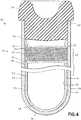
- FIG. 4shows the fill-line indicator as a wide band indicator 26, according to a first aspect of the invention, wherein the indicator 26 is integrally formed with the inner surface 58 of the second tubular member 52 having a first predetermined width 28 defining a range for the expected fill volume for the container.
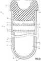
- FIG. 5shows the fill-line indicator as an upper line 34 and a lower line 36, according to a second aspect of the invention, wherein these lines are integrally formed with the inner surface 58 of the second tubular member to define a range of volume 38 indicating the expected fill volume of the container 10.
- FIG. 4shows the fill-line indicator as a wide band indicator 26, according to a first aspect of the invention, wherein the indicator 26 is integrally formed with the inner surface 58 of the second tubular member 52 having a first predetermined width 28 defining a range for the expected fill volume for the container.
- FIG. 5shows the fill-line indicator as an upper
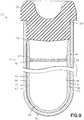
- FIG. 6shows the fill-line indicator as a single thin line 40, according to a third aspect of the invention wherein this line 40 is positioned on an inner surface 58 of the second tubular member 52.
- This single thin line 40has a second predetermined width 42 which indicates the minimum expected fill-line for the container.
- this fill-line indicatorit is preferable to place on an inner surface of a tube when injection molding, as processing and removal of the molded tube having the indicator thereon is easier.
- the fill- line indicatoron the outer tube when using, for example, an outer tube formed from polyethylene terephthalate, as the opacity of the fill-line provides a greater contrast with this type of material, than with the inner tube such as when such tube is formed from a polypropylene material.
- such tube-in-tube container configurationsmay further include an outer roughened or textured surface on the inner tube to permit air to escape from the space between the containers during assembly of the inner tube within the outer tube, such as the enlarged textured top portion shown and described in the above- mentioned and incorporated U.S. Patent No. 6,910,597 .
- Such a roughened or textured surface at the enlarged top portion of the inner tubeis separate and distinct from the textured surface representing the fill-line indicator such as fill-line indicators 26, 34, 36, 40, which also represents a roughened or textured surface, but is spaced from the top portion of the inner tube and is directly tied to the fill volume of the container, and not intended to function as an assembly feature for escape of air.
- the location of the indicatoris also positioned with respect to the desired draw volume (of blood) and the amount of reagent, wherein the amount of reagent is chosen for the specific draw volume, and the location of the fill-line indicator 18 con-elates to the amount of draw volume and reagent.
- the fill-line indicator 18can be formed on an inner surface 50 of the first or inner tubular member 44.
- FIG. 7shows the fill-line indicator as a wide band indicator 26, according to a first aspect of the invention, wherein the indicator 26 is integrally formed with the inner surface 50 of the first tubular member 44 having a first predetermined width 28 defining a range for the expected fill volume for the container.
- FIG. 8shows the fill-line indicator as an upper line 34 and a lower line 36, according to a second aspect of the invention, wherein these lines are integrally formed with the inner surface 50 of the first tubular member 44 to define a range of volume 38 indicating the expected fill volume of the container 10.
- FIG. 9shows the fill-line indicator as a single thin line 40, according to a third aspect of the invention wherein the line is positioned integral with inner surface 50 of the first tubular member 44.
- This single thin line 40has a second predetermined width 42 which indicates the minimum expected fill-line for the container.
- the fill-line indicator 18can be formed on an outer surface 51 of the first or inner tubular member 44.
- FIG. 10shows the fill-line indicator as a wide band indicator 26, wherein the indicator 26 is integrally formed with the outer surface 51 of the first tubular member 44 having a first predetermined width 28 defining a range for the expected fill volume for the container
- FIG. 11shows the fill-line indicator as an upper line 34 and a lower line 36, wherein these lines are integrally formed with the outer surface 51 of the first tubular member 44 to define a range of volume 38 indicating the expected fill volume of the container 10.
- FIG. 10shows the fill-line indicator as a wide band indicator 26, wherein the indicator 26 is integrally formed with the outer surface 51 of the first tubular member 44 having a first predetermined width 28 defining a range for the expected fill volume for the container
- FIG. 11shows the fill-line indicator as an upper line 34 and a lower line 36, wherein these lines are integrally formed with the outer surface 51 of the first tubular member 44 to define a range of
- FIG. 12shows the fill-line indicator as a single thin line 40, according to a third aspect of the invention wherein the line is positioned integral with outer surface 50 of the first tubular member 44.
- This single thin line 40has a second predetermined width 42 which indicates the minimum expected fill-line for the container.
- the fill-line indicator 18 of the present inventioncan be used with other types of containers besides the tube-in-tube configurations.
- the fill-line indicator 18can be used with a single tubular member 60.
- the fill-line indicator 18can be formed on an inner surface 61 of the tubular member 60 as a wide band indicator 26, wherein the indicator 26 is integrally formed with the inner surface 61 of the tubular member 60 and the indicator has a first predetermined width 28 defining a range for the expected fill volume for the container.
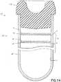
- FIG. 14shows the fill-line indicator as an upper line 34 and a lower line 36, wherein these lines are integrally formed with the inner surface 61 of the tubular member 60 to define a range of volume 38 indicating the expected fill volume of the container 10.
- FIG. 15shows the fill-line indicator as a single thin line 40, wherein this line 40 is positioned on an inner surface 61 of the tubular member 60. This single thin line 40 has a second predetermined width 42 which indicates the minimum expected fill-line for the container.
- the container assemblycomprises a tubular member having a first end 70, a second end 72, and a sidewall 74 extending circumferentially between the first end 70 and the second end 72.
- the fill-line indicator 18corresponds to at least a minimum expected fill volume of the collection container.
- the first end 70 and second end 72may be closed by closures 24.
- the fill-linesare described above such that they are parallel with the circumference of the open end of the container or container assembly, the fill-line may be disposed on the container or assembly at an angle such that the volume of a sample can be recognized when the container or assembly is at an angle.
- the fill-lines described aboveare positioned such that it surrounds the entire circumference of the container or assembly, in some embodiments, the fill-line(s) may surround only a portion of the container or assembly and/or may be situated in segments (e.g., broken line(s)).
- fill-line(s) situated on a container assemblymay be situated on the outer tube, inner tube, or both tubes.
- additional types of container structuressuch as collection bags may employ one or more of the described fill-line features.
Landscapes
- Health & Medical Sciences (AREA)
- Life Sciences & Earth Sciences (AREA)
- Hematology (AREA)
- General Health & Medical Sciences (AREA)
- Molecular Biology (AREA)
- Physics & Mathematics (AREA)
- Engineering & Computer Science (AREA)
- Biomedical Technology (AREA)
- Heart & Thoracic Surgery (AREA)
- Medical Informatics (AREA)
- Biophysics (AREA)
- Surgery (AREA)
- Animal Behavior & Ethology (AREA)
- Pathology (AREA)
- Public Health (AREA)
- Veterinary Medicine (AREA)
- Chemical & Material Sciences (AREA)
- Analytical Chemistry (AREA)
- Clinical Laboratory Science (AREA)
- Chemical Kinetics & Catalysis (AREA)
- Vascular Medicine (AREA)
- Investigating Or Analysing Biological Materials (AREA)
- Sampling And Sample Adjustment (AREA)
Description
- The present invention relates to a biological sample container and, more particularly, to a biological fluid collection container having at least one fill-line indicator.
- Biological sample containers have historically been used for the collection of specimens, such as blood and other bodily fluids, for the purpose of, for example, performing diagnostic tests. In many cases, a predetermined volume of specimen is required to perform a specific test, and such containers are often utilized to facilitate collection of a precise test-specific specimen volume, for example, with a fluid collection container such as a blood collection tube. In some such sample containers, a pre-measured additive, such as a preservative or anticoagulant, is deposited into the container to preserve or otherwise prepare the sample. Accordingly, it is important that the amount of fluid sample collected within the container correspond to the volume of additive within the container and/or the desired test volume.
- Traditional methods of measuring specimen volume have included placing an adhesive label on the exterior surface of the sample container at a precise location. This allows medical personnel to measure the specimen volume by aligning the amount of liquid within the container with a designation on the label, or the upper or lower edge of the label. This method, however, can have significant drawbacks. Complicated machinery is necessary to properly align the label on the exterior of the sample container. Errors in label placement can cause inaccurate fill volumes and consequently inaccurate corresponding test results, especially where sample to additive ratios are to be properly managed and maintained. Sample containers having misaligned labels are typically discarded as defective products and contribute to increased costs. In addition, labels affixed to the exterior of a sample container can become damaged through routine procedures, and can be easily covered over by additional patient or sample collection indicia.
- Consequently, there is a need for an improved sample container that allows medical personnel to visually obtain a precise volume of specimen and/or a combined expected volume of specimen with a reagent present in the container.
- According to an aspect of the present invention, a specimen collection container assembly according to claim 1 is provided.
- According to yet another aspect of the present invention, a method of making a specimen collection container according to claim 9 is provided.
- According to a further aspect of the present invention, the fill-line indicator can comprise a single line extending at least partially circumferentially about a portion of the second sidewall wherein this single line has a first predetermined width that corresponds to a minimum volume of the expected fill volume of the collection container. Alternatively, according to a another aspect of the present invention, the fill-line indicator can comprise an upper and lower line extending at least partially circumferentially about a portion of one of the first and second sidewall and spaced a predetermined distance form each other and wherein the upper line defines a maximum expected fill volume and the lower line defines a minimum expected fill volume and wherein the spacing between the upper and lower line defines a range of volumes of the expected fill volume of the collection container. According to yet another aspect of the present invention, the fill-line indicator can also comprise a single line extending at least partially circumferentially about a portion of the second sidewall wherein this single line has a second predetermined width defined by an upper boundary and lower boundary. The upper boundary defines a maximum expected fill volume, the lower boundary defines a minimum expected fill volume and the second predetermined width defines a range of volumes of the expected fill volume of the collection container.
- The fill-line indicator can be a textured surface on the second sidewall of the second tubular member. This textured surface is capable of diffusing light and/or forming an opaque surface on the container and can be formed during an injection molding process.
- Further details and advantages will be understood from the following description of the preferred embodiments, taken with the accompanying drawings, wherein like reference numerals represent like elements throughout.
FIG. 1 is a perspective view of a container having a single wide band fill-line indicator according to a first aspect of the invention;FIG. 2 is a perspective view of a container having a pair of fill-line indicators according to a second aspect of the invention;FIG. 3 is a perspective view of a container having a single fill-line indicator showing a minimum expected fill volume according to a third aspect of the invention;FIG. 4 shows a cross-sectional view of the wide band fill-line ofFIG. 1 formed on an inner surface of a second tube according to a first embodiment of the invention;FIG. 5 shows a cross-sectional view of the pair of fill-line indicators ofFIG. 2 formed on an inner surface of a second tube according to the first embodiment of the invention;FIG. 6 shows a cross-sectional view of the thin line fill-line ofFIG. 3 formed on an inner surface of a second tube according to the first embodiment of the invention;FIG. 7 shows a cross-sectional view of the wide band fill-line ofFIG. 1 formed on an inner surface of a first tube, which is not covered by the present invention;FIG. 8 shows a cross-sectional view of the pair of fill-line indicators ofFIG. 2 formed on an inner surface of a first tube, which is not covered by the present invention;FIG. 9 shows a cross-sectional view of the thin line fill-line ofFIG. 3 formed on an inner surface of a first tube, which is not covered by the present invention;FIG. 10 shows a cross-sectional view of the wide band fill-line ofFIG. 1 formed on an outer surface of a first tube, which is not covered by the present invention;FIG. 11 shows a cross-sectional view of the pair of fill-line indicators ofFIG. 2 formed on an outer surface of a first tube, which is not covered b the present invention;FIG. 12 shows a cross-sectional view of the thin line fill-line ofFIG. 3 formed on an outer surface of a first tube, which is not covered by the present invention;FIG. 13 shows a cross-sectional view of the wide band fill-line ofFIG. 1 formed on an inner surface of a single tube, which is not covered by the present invention;FIG. 14 shows a cross-sectional view of the pair of fill-line indicators ofFIG. 2 formed on an inner surface of a single tube, which is not covered by the present invention;FIG. 15 shows a cross-sectional view of the thin line fill-line ofFIG. 3 formed on an inner surface of a single tube, which is not covered by the present invention; andFIG. 16 shows a perspective view of a double-open ended tube, which is not covered by the present invention.- For purposes of the description hereinafter, spatial or directional terms shall relate to the invention as it is oriented in the drawing figures. However, it is to be understood that the invention may assume various alternative variations, except where expressly specified to the contrary. It is also to be understood that the specific components illustrated in the attached drawings, and described in the following specification, are simply exemplary embodiments of the invention. Hence, specific dimensions and other physical characteristics related to the embodiments disclosed herein are not to be considered as limiting.
- Reference is now made to
FIGS. 1-3 which show a perspective view of a collection container, generally indicated as 10, such as a biological fluid specimen collection container. Thecontainer 10, comprises a tubular member having anopening 12, a closedbottom 14, and asidewall 16 extending circumferentially between theopening 12 and the closedbottom 14 to form a tube. Thecontainer 10 has a predetermined internal volume capable of receiving a specimen sample therein. A fill-line indicator, generally indicated as 18, is positioned on thesidewall 16. This fill-line indicator 18 corresponds to at least a minimum expected fill volume of thecollection container 10. Whilecontainer 10 is described in certain embodiments herein in the form of a biological fluid collection container such as a blood collection tube, and in particular, an evacuated blood collection tube, it is contemplated that embodiments of the invention can be directed to any biological sample container. - The
container 10 ofFIGS. 1-3 have aninner surface 20 and anouter surface 22. Blood, urine, and/or other bodily fluids may be collected within thecontainer assembly 10 for subsequent testing procedures. Thecontainer 10 may comprise, for example, glass or a polymeric composition, such as polypropylene, nylon, polystyrene, cyclic olefin copolymer polyethylene terapthalate and/or polyethylene. The container may have any suitable length L and any suitable width W (or diameter) consistent with its intended use. In one embodiment, thecontainer 10 represents a collection tube having an expected fill capacity of from about 1 to about 7 milliliters (ml), such as about 2.7 ml. In another embodiment, the container can have an expected fill capacity of about 1.8 ml. - The
container 10 comprises a fill-line indicator 18 integrally formed with thesidewall 16 that corresponds to a desired or expected specimen fill capacity. In some embodiments, the desired specimen fill capacity may include only the specimen. In other embodiments, the desired specific fill capacity may include the specimen and the additive. The expected fill volume can be defined as only the volume of the biological fluid, such as blood entering the container or the volume of biological fluid plus an additive such as a reagent. In other cases, the expected fill volume can include the volume of the biological fluid plus a separator (gel or mechanical) and/or the volume of the biological fluid plus a separator and an additive. - The fill-
line indicator 18 can indicate at least a desired minimum expected fill volume and can correspond to the meniscus of a liquid specimen contained withincontainer assembly 10. The fill-line indicator 18 can be disposed continuously about the circumference of the sidewall of thecontainer 10 or alternatively, the fill-line indicator 18 can extend at least partially circumferentially about a portion of thesidewall 16. - In embodiments disclosed herein, the fill-
line indicator 18 provides the container with an indication as to the expected fill volume for acontainer 10 when thecontainer 10 is positioned vertically, in this case, upright, i.e., in a closure-up position. In this manner, the fill-line volume indicator 18 provides a confirmation as to whether an amount of sample within thecontainer 10 is the desired or expected fill volume for thecontainer 10. Such a fill-line indicator 18 is particularly helpful for sample collection containers, such as for determining whether the amount of sample within a container matches the particular predetermined draw volume for the specific collection container. In other embodiments, the fill-line volume indicator 18 provides an indication as to the desired or expected fill volume for a container when the container is positioned in a non-vertical position. For example, blood collection containers typically include a negative pressure or vacuum within the interior thereof. Apierceable closure 24 is used to cap thecontainer 10 and maintain this negative pressure therein. In use, a blood collection needle accesses a patient's blood vessel, and is placed in fluid communication with the interior of theblood collection container 10. The negative pressure within thecontainer 10 draws a blood sample from the blood vessel, through the needle and into the interior of the collection container. Eventually, the pressure within thecollection container 10 is equilibrated with the blood pressure, at which time no additional sample is drawn into the collection container. Accordingly, the interior of thecollection container 10 may include a negative pressure to provide sufficient vacuum within thecollection container 10 to ensure that a predetermined volume of blood is drawn into the container based on that vacuum. - Further,
sample containers 10 may incorporate specific reagents therein, associated with a desired test to be performed on the sample. One example of a reagent includes a citrate. The amount of reagent may be particularly tailored to the specific expected fill volume of sample for the container. If the amount of sample drawn into thecontainer 10 does not match the specific expected fill volume of the specimen sample and reagent, the reagent may not properly react with the sample, thereby possibly providing inaccurate testing results. The fill-line indicator 18 provides a mechanism to facilitate ensuring that the proper volume of sample for reacting with the reagent in the container is collected within thecontainer 10. For example, long-term storage of evacuated collection containers can result in reduced vacuum therein, thereby reducing the draw volume for thecontainer 10. Moreover, during an initial blood draw, the needle may include air therein which is displaced into the first collection container used in the draw. Such air may decrease the overall fill volume for thecontainer 10, such that an insufficient amount of blood is drawn into the container for the reagent contained therein. By providing the fill-line indicator 18, the user can confirm that the appropriate amount of sample expected for thatcontainer 10 has in fact been collected within thecontainer 10 immediately after the blood draw. Moreover, by providing the fill-line indicator 18 integral with the container itself, the expected fill volume is effectively set and is incorporated directly with the container, without the chance of misalignment of a separate label identifying the intended or expected fill volume. - Still further, the fill-
line indicator 18 can provide confirmation to a lab technician as to whether the volume contained within acontainer 10 is the expected fill volume, particularly for a specific type of container. This indication may also be useful for confirming whether a sample has already been removed from thecontainer 10 for analysis. - In one embodiment, the fill-
line indicator 18 represents a portion ofsidewall 16 that has a different profile, surface, texture, etc., and therefore is adapted to diffuse light passing through thesidewall 16 differently than the remaining portion ofsidewall 16 definingcontainer 10. - The fill-
line indicator 18 may be formed by a variety of techniques. For example, the fill-line indicator 18 can comprise a ridge that is raised from thesidewall 16 of the assembly, extending circumferentially about thecontainer 10. The ridge can extend from the surface of thesidewall 16. In another embodiment, the ridge can be recessed into theside wall 16 to form a groove. The height of such a ridge and/or the depth of such a groove may be any desired amount, so long as the dimensions of the ridge and/or the groove provide a unique identifier to the human eye (or some other indication) which differentiates the ridge and/or groove from thesidewall 16 to represent the fill-line indicator. In a further embodiment, the fill-line indicator 18 can comprise a colored band that is distinct from the color of thesidewall 16. In such an embodiment,sidewall 16 may be a generally transparent material, with a separate colored band sprayed, stenciled, or otherwise applied to the inner or outer surface ofsidewall 16 to form the fill-line indicator 18. - Preferably, the fill-
line indicator 18 may be formed during an injection molding process for forming thecontainer 10. In such a process, a mold core member cooperates with a mold cavity and plastic material is injected into the cavity between the core and the cavity to form the tubular member. The fill-line indicator 18 is formed by providing a roughened or textured surface at least partially circumventing a perimeter of the core member. Accordingly, during the molding process, this roughened surface is imparted to the inner surface of thesidewall 16 of thecontainer 10. Providing the roughened or textured surface on the core member, as opposed to the cavity member, of the injection molding device provides the advantage that it is easier to eject the tube off of the core. If a textured or roughened surface were provided in the cavity, such as to provide the fill-line indicator 18 on an outer surface of thesidewall 16, then there is a chance that the tube may become stuck within the cavity. As stated above, it is easier to eject the tube from the core than it is to remove a tube from within a cavity. - In yet another embodiment, the fill-
line indicator 18 may comprise a region of thesidewall 16 that has been modified by a surface treatment to impart a distinct visual appearance and/or texture as compared to the remainder of thesidewall 16. In such an embodiment, the region forming fill-line indicator 18 may have a translucent or opaque property, with the remainder of theside wall 16 exhibiting a highly polished transparent appearance. For example, the region ofsidewall 16 defining fill-line indicator 22 may be modified by electrical discharge machining, etching, or other similar process to impart a textured appearance as compared to the remainder of theside wall 16. In one embodiment, a portion ofside wall 16 intended to define fill-line indicator 18 is roughened to define an array of peaks and valleys. For example, the roughened portion of sidewall may be formed by an electrical discharge machining process so as to form an electrical discharge machining finish. The finished part then is compared visually with a visual standard, such as the Charmilles Technologies Company visual surface standard (Charmilles Technology Company, Lincolnshire, IL). Using this standard practice, the roughened surface defines a finish of, for example, 1.6 to 12.5 microns and more preferably, a finish of 4.5 to 12.5 microns. Additionally, the roughened surface may be cross-referenced visually to a Charmilles finish number, such as between 24 and 42, and, more preferably, between 30 and 42. Such a surface provides fill-line indicator 18 with a finish which is distinct from the remainder ofsidewall 16, such as a polished surface. Accordingly, the surface defining fill-line indicator 18 diffuses light differently than the remainder ofsidewall 16. In this manner, when a liquid sample is contained withincontainer 10, a clear visual indication is observed when the sample is filled to a level at fill-line indicator 18, due to the difference in light diffused through theside wall 16. It is contemplated that certain finishes for fill-line indicator 18 may provide an enlarging effect to the sample when the meniscus of a fluid level is at the fill-line indicator 18, providing an apparent indication of reaching such level of containment. - The thickness or length of the fill-
line indicator 18 alongsidewall 16 defining the length ofcontainer 10 may be any desired length, provided that, in one embodiment, such length represents the suitable range of volume for a specific test when the fluid meniscus of a sample contained withincontainer 10 is aligned therewith. FIG. 1 shows a fill-line indicator 18 according to a first aspect of the invention wherein this fill-line indicator 18 comprises single wide band orline 26 extending at least partially circumferentially about a portion of thesidewall 16. Thissingle band 26 has a firstpredetermined width 28 defined by anupper boundary 30 and alower boundary 32. Theupper boundary 30 defines a maximum expected fill volume. Thelower boundary 32 defines a minimum expected fill volume. The secondpredetermined width 28 defines a range of volumes for the expected fill volume of thecollection container 10.FIG. 2 shows a fill-line indicator 18 according to a second aspect of the invention wherein this fill-line indicator 18 comprises anupper line 34 andlower line 36 extending at least partially circumferentially about a portion of thesidewall 16. Theupper line 34 andlower line 36 are spaced apredetermined distance 38 from each other. Theupper line 34 defines a maximum expected fill volume. Thelower line 36 defines a minimum expected fill volume. Thepredetermined distance 38 between the upper 34 andlower line 36 defines a range of volume of the expected fill volume of thecollection container 10.FIG. 3 shows a fill-line indicator 18 according to a third aspect of the invention wherein this fill-line indicator 18 comprises a singlethin line 40 extending at least partially circumferentially about a portion of thesidewall 16. Thissingle line 40 has a secondpredetermined width 42 corresponding to a minimum volume of the expected fill volume of the collection container.- As noted above, specific reagents may be included within
container 10. Fill-line indicator 18 may therefore be associated with a specific volume of sample contained within the container to properly react with such a reagent. Accordingly, in embodiments of the invention,container 10 may include an additive, such as sodium citrate, tri-potassium ethylenediamine tetra-acetate (K3 EDTA), lithium heparin, or the like, which may be added intocontainer 10 in a liquid format, a spray-dried format, or some other format. - As shown in
FIGS. 4-12 , thecontainer assembly 10 can comprise a dual tube-in-tube configuration. This type of configuration comprises a firsttubular member 44 having afirst opening 46, a first closed bottom 48, and afirst sidewall 49 extending circumferentially between thefirst opening 46 and the firstclosed bottom 48. The firsttubular member 44 is capable of receiving a specimen sample therein. The container further comprises a secondtubular member 52 having asecond opening 54, a second closed bottom 56, and asecond sidewall 57 extending circumferentially between thesecond opening 54 and the secondclosed bottom 56. The firsttubular member 44 is disposed within the secondtubular member 52. A fill-line indicator 18 is positioned on one of the first and second sidewall. This fill-line indicator 18 corresponds to at least a minimum expected fill volume of thecollection container 10. The firsttubular member 44 or theinner tube 42, in this instance, has an axial length that is less than the secondtubular member 52 or outer tube. As a result, aclosure 24 can be inserted into the tops of the container assembly for secure sealing engagement with portions of both the first and secondtubular members outer surface 51 of the firsttubular member 44 and theinner surface 58 of the secondtubular member 52 may be dimensioned to substantially nest with one another and may be structured in a manner to prevent foreign matter (such as biological sample) from entering any space that may exist between theinner surface 58 of the secondtubular member 52 and theouter surface 51 of the firsttubular member 44. Such a tube-in-tube configuration is described in detail inU.S. Patent No. 6,910,597 to Iskra , the entirety of which is incorporated herein by reference thereto. - In a tube-in-tube configuration, differing materials may be used for each of the tubes, for example, one tube may comprise glass and another tube may comprise a polymeric composition to provide improved liquid and vapor resistance. Alternatively, both tubes may be formed from a polymeric composition wherein one of the nested containers may be formed from a material that, for example, exhibits desirable gas barrier characteristics, and the other of the containers may be formed from a material that, for example, provides a moisture barrier. The inner container is formed from a material that has a proper surface for the specified clinical performance of the material being stored in the container assembly. Materials exhibiting desirable gas barrier characteristics include: acrylic polymers and copolymers, including acrylonitrile-butadiene-styrene (ABS), styrene-acrylonitrile (SAN); ethylene vinyl alcohol (EVA); polyesters; polyethylene terephthalate (PET); polyethylene terephthalate glycol (PETG); polyethylene terephthalate naphthalene (PETN); polyethylene naphthalene (PEN); and engineered thermoplastics, including polycarbonate and blends thereof. Materials that exhibit desirable moisture or vapor barrier characteristics include: polyolefins, including polyethylene, polypropylene and copolymers thereof, cyclic olefin copolymers and chloro- and fluoro-polymers, including polyvinylidene chloride (PVDC), polyvinylidene fluoride (PVDF), polyvinyl fluoride (PVF), and chlorotrifluoroethylene (CTFE or ACLAR). In one embodiment, the inner or first
tubular member 44 is formed from polypropylene (PP), and the outer or secondtubular member 52 is formed from PET. - The first and second
tubular members - According to a first embodiment of the invention, as shown in
FIGS. 4-6 , the fill-line indicator 18 can be formed on aninner surface 58 of the second or outertubular member 52.FIG. 4 shows the fill-line indicator as awide band indicator 26, according to a first aspect of the invention, wherein theindicator 26 is integrally formed with theinner surface 58 of the secondtubular member 52 having a firstpredetermined width 28 defining a range for the expected fill volume for the container.FIG. 5 shows the fill-line indicator as anupper line 34 and alower line 36, according to a second aspect of the invention, wherein these lines are integrally formed with theinner surface 58 of the second tubular member to define a range ofvolume 38 indicating the expected fill volume of thecontainer 10.FIG. 6 shows the fill-line indicator as a singlethin line 40, according to a third aspect of the invention wherein thisline 40 is positioned on aninner surface 58 of the secondtubular member 52. This singlethin line 40 has a secondpredetermined width 42 which indicates the minimum expected fill-line for the container. As discussed in detail above, it is preferable to place this fill-line indicator on an inner surface of a tube when injection molding, as processing and removal of the molded tube having the indicator thereon is easier. Also, it is preferable to place the fill- line indicator on the outer tube when using, for example, an outer tube formed from polyethylene terephthalate, as the opacity of the fill-line provides a greater contrast with this type of material, than with the inner tube such as when such tube is formed from a polypropylene material. - It is further contemplated that such tube-in-tube container configurations may further include an outer roughened or textured surface on the inner tube to permit air to escape from the space between the containers during assembly of the inner tube within the outer tube, such as the enlarged textured top portion shown and described in the above- mentioned and incorporated
U.S. Patent No. 6,910,597 . Such a roughened or textured surface at the enlarged top portion of the inner tube is separate and distinct from the textured surface representing the fill-line indicator such as fill-line indicators line indicator 18 con-elates to the amount of draw volume and reagent. - According to another embodiment, which is not covered by the present invention, as shown in
FIGS. 7-9 , the fill-line indicator 18 can be formed on aninner surface 50 of the first or innertubular member 44.FIG. 7 shows the fill-line indicator as awide band indicator 26, according to a first aspect of the invention, wherein theindicator 26 is integrally formed with theinner surface 50 of the firsttubular member 44 having a firstpredetermined width 28 defining a range for the expected fill volume for the container. FIG. 8 shows the fill-line indicator as anupper line 34 and alower line 36, according to a second aspect of the invention, wherein these lines are integrally formed with theinner surface 50 of the firsttubular member 44 to define a range ofvolume 38 indicating the expected fill volume of thecontainer 10.FIG. 9 shows the fill-line indicator as a singlethin line 40, according to a third aspect of the invention wherein the line is positioned integral withinner surface 50 of the firsttubular member 44. This singlethin line 40 has a secondpredetermined width 42 which indicates the minimum expected fill-line for the container.- According to another embodiment, which is not covered by the present invention, as shown in
FIGS. 10-12 , the fill-line indicator 18 can be formed on anouter surface 51 of the first or innertubular member 44.FIG. 10 shows the fill-line indicator as awide band indicator 26, wherein theindicator 26 is integrally formed with theouter surface 51 of the firsttubular member 44 having a firstpredetermined width 28 defining a range for the expected fill volume for the container,FIG. 11 shows the fill-line indicator as anupper line 34 and alower line 36, wherein these lines are integrally formed with theouter surface 51 of the firsttubular member 44 to define a range ofvolume 38 indicating the expected fill volume of thecontainer 10.FIG. 12 shows the fill-line indicator as a singlethin line 40, according to a third aspect of the invention wherein the line is positioned integral withouter surface 50 of the firsttubular member 44. This singlethin line 40 has a secondpredetermined width 42 which indicates the minimum expected fill-line for the container. - According to another embodiment, which is not covered by the present invention, and as shown in
FIGS. 13-15 of the invention, the fill-line indicator 18 of the present invention can be used with other types of containers besides the tube-in-tube configurations. For example, the fill-line indicator 18 can be used with asingle tubular member 60. As shown inFIG. 13 , the fill-line indicator 18 can be formed on aninner surface 61 of thetubular member 60 as awide band indicator 26, wherein theindicator 26 is integrally formed with theinner surface 61 of thetubular member 60 and the indicator has a firstpredetermined width 28 defining a range for the expected fill volume for the container.FIG. 14 shows the fill-line indicator as anupper line 34 and alower line 36, wherein these lines are integrally formed with theinner surface 61 of thetubular member 60 to define a range ofvolume 38 indicating the expected fill volume of thecontainer 10.FIG. 15 shows the fill-line indicator as a singlethin line 40, wherein thisline 40 is positioned on aninner surface 61 of thetubular member 60. This singlethin line 40 has a secondpredetermined width 42 which indicates the minimum expected fill-line for the container. - Although the previously discussed embodiments have been directed to closed end tubular containers, the use of a fill-
line indicator 18 may be used on double-ended open tubes, such as shown inFIG. 16 . In this embodiment, the container assembly comprises a tubular member having afirst end 70, asecond end 72, and asidewall 74 extending circumferentially between thefirst end 70 and thesecond end 72. The fill-line indicator 18 corresponds to at least a minimum expected fill volume of the collection container. Thefirst end 70 andsecond end 72 may be closed byclosures 24. - While specific embodiments of the invention have been described in detail, it will be appreciated by those skilled in the art that various modifications and alternatives to those details could be developed in light of the overall teachings of the disclosure. For example, while the fill-lines are described above such that they are parallel with the circumference of the open end of the container or container assembly, the fill-line may be disposed on the container or assembly at an angle such that the volume of a sample can be recognized when the container or assembly is at an angle. In addition, while the fill-lines described above are positioned such that it surrounds the entire circumference of the container or assembly, in some embodiments, the fill-line(s) may surround only a portion of the container or assembly and/or may be situated in segments (e.g., broken line(s)). Further, it should be noted that the fill-line(s) situated on a container assembly may be situated on the outer tube, inner tube, or both tubes. Moreover, while the embodiments describe the inclusion of fill-line(s) on a container or assembly in the form of one more tubes, additional types of container structures (such as collection bags) may employ one or more of the described fill-line features.
Claims (13)
- A specimen collection container assembly comprising: a first tubular member (44) having a first opening (46), a first closed bottom (48), and a first sidewall (49) extending circumferentially between said first opening (46) and said first closed bottom (48), said first tubular member (44) capable of receiving a specimen sample therein; a second tubular member (52) having a second opening (54), a second closed bottom (56), and a second sidewall (57) extending circumferentially between said second opening (54) and said second closed bottom (56), said first tubular member (44) being disposed within said second tubular member (52); and a fill-line indicator (18) integrally formed with the second sidewall (57), said fill-line indicator (18) corresponding to at least a minimum expected fill volume of the collection container,
wherein said fill-line indicator (18) is integrally formed with said inner surface (58) of said second sidewall (57) as a roughened portion of said inner surface (58) of said second sidewall (57), wherein the first tubular member (44) defines an internal volume. - The container assembly of claim 1 wherein the fill-line indicator is a textured surface capable of diffusing light.
- The container assembly of claim 1 wherein the fill-line indicator comprises a single wide band extending at least partially circumferentially about a portion of said second sidewall, said single band having a first predetermined width defined by an upper boundary and a lower boundary, said upper boundary defining a maximum expected fill volume, said lower boundary defining a minimum expected fill volume.
- The container assembly of claim 1 wherein the fill-line indicator comprises an upper line and a lower line extending at least partially circumferentially about a portion of said second sidewall and spaced a predetermined distance from each other, said upper line defining a maximum expected fill volume and said lower line defining a minimum expected fill volume.
- The container assembly of claim 1 wherein the fill-line indicator comprises a line extending at least partially circumferentially about a portion of said second sidewall, said single line having a second predetermined width corresponding to a minimum volume of the expected fill volume of said collection container.
- The container assembly of claim 1 wherein said first tubular member is formed from a moisture barrier material preferably comprising polypropylene and said second tubular member is formed from a vapor barrier material preferably comprising polyethylene terephthalate.
- The container assembly of claim 1 wherein the first tubular member defines an internal volume and the container assembly further includes a pierceable closure which is used to cap the container such that the negative pressure of the internal volume with respect to atmosphere is maintained.
- Use of the container assembly of claim 7 wherein the fill-line indicator indicates at least a minimum expected fill volume of the specimen sample according to the reduced pressure of the internal volume of said container.
- Use of the container assembly of claim 7 wherein the fill-line indicator indicates at least a minimum expected fill volume of the specimen sample in combination with a pre-filled reagent located within said container in accordance with the reduced pressure of the internal volume of said container.
- A method of making a specimen collection container comprising: molding a first tubular member having a first opening, a first closed bottom, and a first sidewall extending circumferentially between said first opening and said first closed bottom, said first tubular member having a predetermined volume for receiving a specimen sample therein; molding a second tubular member having a second opening, a second closed bottom, and a second sidewall extending circumferentially between said second opening and said second closed bottom; providing a fill-line indicator integrally formed with at least one of said first and second sidewall, said fill-line indicator corresponding to at least a minimum expected fill volume of the collection container,
positioning said first tubular member within said second tubular member, wherein at least said second tubular member is formed by an injection molding process including a core member and said fill-line indicator is formed on an inner surface of said second sidewall by providing a roughened surface at least partially circumventing a perimeter of said core member. - The method of claim 10 wherein the fill-line indicator comprises a single wide band extending at least partially circumferentially about a portion of said second sidewall, said band having a first predetermined width defined by an upper boundary and a lower boundary, said upper boundary defining a maximum expected fill volume, said lower boundary defining a minimum expected fill volume.
- The method of claim 10 wherein the fill-line indicator comprises an upper and lower line extending at least partially circumferentially about a portion of said second sidewall and spaced a predetermined distance from each other, said upper fill-line defining a maximum expected fill volume and said lower line defining a minimum expected fill volume.
- The method of claim 10 wherein the fill-line indicator comprises a line extending at least partially circumferentially about a portion of said second sidewall, said line having a first predetermined width corresponding to a minimum expected volume of the expected fill volume of said collection container.
Priority Applications (2)
| Application Number | Priority Date | Filing Date | Title |
|---|---|---|---|
| EP09160121.1AEP2110174B1 (en) | 2006-09-08 | 2007-09-07 | Sample container with physical fill-line indicator |
| PL09160121TPL2110174T3 (en) | 2006-09-08 | 2007-09-07 | Sample container with physical fill-line indicator |
Applications Claiming Priority (2)
| Application Number | Priority Date | Filing Date | Title |
|---|---|---|---|
| US84316006P | 2006-09-08 | 2006-09-08 | |
| PCT/US2007/077890WO2008031036A1 (en) | 2006-09-08 | 2007-09-07 | Sample container with physical fill-line indicator |
Related Child Applications (2)
| Application Number | Title | Priority Date | Filing Date |
|---|---|---|---|
| EP09160121.1ADivisionEP2110174B1 (en) | 2006-09-08 | 2007-09-07 | Sample container with physical fill-line indicator |
| EP09160121.1ADivision-IntoEP2110174B1 (en) | 2006-09-08 | 2007-09-07 | Sample container with physical fill-line indicator |
Publications (2)
| Publication Number | Publication Date |
|---|---|
| EP2063989A1 EP2063989A1 (en) | 2009-06-03 |
| EP2063989B1true EP2063989B1 (en) | 2017-01-25 |
Family
ID=38846879
Family Applications (2)
| Application Number | Title | Priority Date | Filing Date |
|---|---|---|---|
| EP07842058.5AActiveEP2063989B1 (en) | 2006-09-08 | 2007-09-07 | Sample container with physical fill-line indicator |
| EP09160121.1AActiveEP2110174B1 (en) | 2006-09-08 | 2007-09-07 | Sample container with physical fill-line indicator |
Family Applications After (1)
| Application Number | Title | Priority Date | Filing Date |
|---|---|---|---|
| EP09160121.1AActiveEP2110174B1 (en) | 2006-09-08 | 2007-09-07 | Sample container with physical fill-line indicator |
Country Status (9)
| Country | Link |
|---|---|
| US (1) | US9409176B2 (en) |
| EP (2) | EP2063989B1 (en) |
| JP (2) | JP5280363B2 (en) |
| CN (2) | CN101636231A (en) |
| AU (1) | AU2007294555A1 (en) |
| CA (1) | CA2662908C (en) |
| ES (2) | ES2473467T3 (en) |
| PL (1) | PL2110174T3 (en) |
| WO (1) | WO2008031036A1 (en) |
Families Citing this family (24)
| Publication number | Priority date | Publication date | Assignee | Title |
|---|---|---|---|---|
| EP2006657A4 (en)* | 2006-03-09 | 2012-03-21 | Arkray Inc | Method of sampling specimen, test method and dropping pipette and specimen sampler to be used therein |
| EP3616618B1 (en) | 2008-03-05 | 2022-11-30 | Becton, Dickinson and Company | Capillary action collection device |
| US20100256524A1 (en) | 2009-03-02 | 2010-10-07 | Seventh Sense Biosystems, Inc. | Techniques and devices associated with blood sampling |
| WO2011053796A2 (en)* | 2009-10-30 | 2011-05-05 | Seventh Sense Biosystems, Inc. | Systems and methods for treating, sanitizing, and/or shielding the skin or devices applied to the skin |
| US20110178424A1 (en) | 2010-01-19 | 2011-07-21 | Becton, Dickinson And Company | Specimen Collection Container Having a Transitional Fill-Volume Indicator Indicating Extraction Method |
| WO2011094573A1 (en) | 2010-01-28 | 2011-08-04 | Seventh Sense Biosystems, Inc. | Monitoring or feedback systems and methods |
| WO2011163347A2 (en) | 2010-06-23 | 2011-12-29 | Seventh Sense Biosystems, Inc. | Sampling devices and methods involving relatively little pain |
| US20130158482A1 (en) | 2010-07-26 | 2013-06-20 | Seventh Sense Biosystems, Inc. | Rapid delivery and/or receiving of fluids |
| WO2012021801A2 (en) | 2010-08-13 | 2012-02-16 | Seventh Sense Biosystems, Inc. | Systems and techniques for monitoring subjects |
| WO2012064802A1 (en)* | 2010-11-09 | 2012-05-18 | Seventh Sense Biosystems, Inc. | Systems and interfaces for blood sampling |
| US8973293B2 (en)* | 2010-11-19 | 2015-03-10 | Becton, Dickinson And Company | Specimen container label for automated clinical laboratory processing systems |
| US8460620B2 (en)* | 2010-12-03 | 2013-06-11 | Becton, Dickinson And Company | Specimen collection container assembly |
| KR102013466B1 (en) | 2011-04-29 | 2019-08-22 | 세븐쓰 센스 바이오시스템즈, 인크. | Delivering and/or receiving fluids |
| US20130158468A1 (en) | 2011-12-19 | 2013-06-20 | Seventh Sense Biosystems, Inc. | Delivering and/or receiving material with respect to a subject surface |
| WO2012149155A1 (en) | 2011-04-29 | 2012-11-01 | Seventh Sense Biosystems, Inc. | Systems and methods for collecting fluid from a subject |
| CN103874461B (en) | 2011-04-29 | 2017-05-10 | 第七感生物系统有限公司 | Devices for collecting and/or manipulating blood spots or other bodily fluids |
| NL2009802C2 (en)* | 2012-11-13 | 2014-05-14 | Heineken Supply Chain Bv | Container, preform assembly and method and apparatus for forming containers. |
| JP6227361B2 (en)* | 2013-10-04 | 2017-11-08 | 株式会社日立ハイテクノロジーズ | Sample pretreatment equipment |
| US10478379B2 (en)* | 2014-07-17 | 2019-11-19 | Becton, Dickinson And Company | Biological sample containment system and label |
| WO2016044427A1 (en)* | 2014-09-17 | 2016-03-24 | Quest Diagnostics Investments Incorporated | Device and method for evaluating amount of biological sample in a specimen container |
| WO2016179347A1 (en)* | 2015-05-05 | 2016-11-10 | Bullington Gregory J | Devices and methods for verifying a sample volume |
| KR20200009022A (en)* | 2017-05-08 | 2020-01-29 | 산타마리아 클라우디아 | Devices for protecting the inner container |
| WO2022065342A1 (en)* | 2020-09-23 | 2022-03-31 | 積水メディカル株式会社 | Specimen collection container |
| AT525932A1 (en)* | 2022-02-17 | 2023-09-15 | Greiner Bio One Gmbh | Organic material removal assembly |
Citations (2)
| Publication number | Priority date | Publication date | Assignee | Title |
|---|---|---|---|---|
| US4942966A (en)* | 1989-06-05 | 1990-07-24 | Kemp David R | Containment device for a test tube |
| US20040222223A1 (en)* | 2003-05-05 | 2004-11-11 | Becton, Dickinson And Company | Container assembly and method for making assembly |
Family Cites Families (107)
| Publication number | Priority date | Publication date | Assignee | Title |
|---|---|---|---|---|
| US2528259A (en)* | 1947-02-12 | 1950-10-31 | Jasper S Annunziata | Dosage time indicating means |
| US3807955A (en)* | 1971-04-15 | 1974-04-30 | Becton Dickinson Co | Serum/plasma isolator cup |
| US3800780A (en)* | 1972-02-23 | 1974-04-02 | Angelika Elliott | Vacuum indicator |
| NO128095B (en) | 1972-06-29 | 1973-10-01 | O Foss | |
| US3942514A (en)* | 1974-02-28 | 1976-03-09 | Ims Limited | Arterial blood sampling device with indicator |
| DE2510783A1 (en)* | 1975-03-08 | 1976-09-16 | Dieter Prange | SELF-ADHESIVE LETTERS OR THE SAME CHARACTERS |
| US4125376A (en)* | 1977-04-22 | 1978-11-14 | The United States Of America As Represented By The Secretary Of The Army | Method for detecting water pollutants |
| US4109530A (en)* | 1977-04-29 | 1978-08-29 | Steven M. Diamond | Specimen transfer container |
| GB2016192B (en)* | 1978-02-17 | 1982-10-13 | Letraset International Ltd | Sign lettering materals |
| US4391780A (en) | 1981-07-06 | 1983-07-05 | Beckman Instruments, Inc. | Container for sample testing |
| US4475915A (en) | 1982-05-07 | 1984-10-09 | Sloane Glenn L | Holder for a syringe and an ampoule |
| US4557070A (en)* | 1982-07-23 | 1985-12-10 | Oyama George C | Plant pot with moisturizing and aeration means |
| JPS5974352U (en)* | 1982-11-11 | 1984-05-19 | 株式会社堀場製作所 | Sample cell for particle size distribution measurement |
| JPS60115852U (en)* | 1984-01-11 | 1985-08-05 | 株式会社 まるきち | Container with lid for storing liquid or powder |
| US4761379A (en)* | 1984-08-09 | 1988-08-02 | Becton, Dickinson And Company | Biological specimen collection device |
| JPS61146250A (en)* | 1984-12-20 | 1986-07-03 | 有限会社 佐藤化成工業所 | Production of blood sampling tube |
| US4981144A (en)* | 1985-03-18 | 1991-01-01 | Henry A. Carels, Jr. | Urine separation and collection device |
| JPS61259670A (en)* | 1985-05-14 | 1986-11-17 | 山越 憲一 | Liquid container |
| JPS62110139A (en) | 1985-11-08 | 1987-05-21 | Hitachi Ltd | Magnetic recording medium inspection device |
| DE3541041A1 (en)* | 1985-11-19 | 1987-05-21 | Sarstedt Kunststoff | BLOOD COLLECTOR |
| JPH0617708Y2 (en)* | 1985-12-28 | 1994-05-11 | 小川化工株式会社 | Benzine container |
| JPS63188768A (en) | 1987-02-02 | 1988-08-04 | Toshiba Corp | automatic chemical analyzer label |
| US5019243A (en)* | 1987-04-03 | 1991-05-28 | Mcewen James A | Apparatus for collecting blood |
| US4871077A (en)* | 1987-04-27 | 1989-10-03 | Doxtech, Inc. | Tamper resistant, tamper evident leak proof container |
| US4827944A (en)* | 1987-07-22 | 1989-05-09 | Becton, Dickinson And Company | Body fluid sample collection tube composite |
| US4873193A (en)* | 1987-08-26 | 1989-10-10 | Forensic Applications Corporation | Method and apparatus for the collection and preservation of fluid biological evidence |
| US4877585A (en)* | 1987-12-09 | 1989-10-31 | Brandeis University | Dilution pipette device |
| US4830217A (en)* | 1988-02-19 | 1989-05-16 | Becton, Dickinson And Company | Body fluid sample collection tube assembly |
| US5059185A (en)* | 1988-03-01 | 1991-10-22 | Ryan Medical, Inc. | Safety needled medical devices |
| US4878597A (en)* | 1988-03-24 | 1989-11-07 | Haast William E | Lyophilization containers |
| JPH028745U (en)* | 1988-06-30 | 1990-01-19 | ||
| JPH0282312A (en) | 1988-09-20 | 1990-03-22 | Toshiba Corp | disk management device |
| JPH0410806Y2 (en)* | 1988-12-13 | 1992-03-17 | ||
| US5024238A (en)* | 1989-01-10 | 1991-06-18 | Cancer Diagnostics, Inc. | Blood withdrawing apparatus and antigen testing method |
| US5071168A (en)* | 1989-01-25 | 1991-12-10 | Shamos Morris H | Patient identification system |
| JPH02212768A (en)* | 1989-02-13 | 1990-08-23 | Terumo Corp | Blood sampling tube |
| DE4000968C1 (en)* | 1990-01-16 | 1991-06-20 | Dieter 2090 Drage De Wendelborn | Blood sampling apparatus - has blood observation chamber mounted in sampling vessel stopper |
| US5048711A (en)* | 1990-06-28 | 1991-09-17 | Sage Products, Inc. | Label indicator for screw thread closure and method of use |
| US5178417A (en)* | 1990-12-31 | 1993-01-12 | Fredrick Eshoo | Automatic ordering method and apparatus |
| US5316952A (en)* | 1991-02-15 | 1994-05-31 | Technical Research Associates, Inc. | Blood sample apparatus and method |
| US5164575A (en)* | 1991-04-23 | 1992-11-17 | Neeley William E | Blood sampling procedure and apparatus |
| US5401110A (en)* | 1991-07-15 | 1995-03-28 | Neeley; William E. | Custom label printer |
| US5215102A (en)* | 1991-10-25 | 1993-06-01 | La Mina Ltd. | Capillary blood antigen testing apparatus |
| US5725832A (en)* | 1992-03-25 | 1998-03-10 | Gundelsheimer; Peter | Laboratory test tubes for the dosing of liquids |
| JP2566867Y2 (en)* | 1992-05-08 | 1998-03-30 | 株式会社吉野工業所 | Container with sub storage room |
| US5556599A (en)* | 1992-06-29 | 1996-09-17 | Ahmed; Syed M. | Blood sample/fluid system |
| US5516564A (en)* | 1993-04-28 | 1996-05-14 | Costar Corporation | Sterile irradiated hydrophobic pipette tip |
| US5871700A (en)* | 1993-12-21 | 1999-02-16 | C.A. Greiner & Sohne Gesellschaft M.B.H. | Holding device with a cylindrical container and blood sampling tube with such a holding device |
| US5447248A (en)* | 1994-01-26 | 1995-09-05 | Rodriguez; Kimberly J. | Indicator for liquid container |
| US5728267A (en)* | 1994-11-15 | 1998-03-17 | Flaherty; James E. | Concentrator for separating small samples in a centrifuge |
| JP3027311B2 (en)* | 1994-12-29 | 2000-04-04 | 川澄化学工業株式会社 | Liquid storage container |
| US5786227A (en)* | 1995-06-07 | 1998-07-28 | Biex, Inc. | Fluid collection kit and method |
| US5786228A (en)* | 1995-06-07 | 1998-07-28 | Biex, Inc. | Fluid collection kit and method |
| US6613410B1 (en)* | 1999-09-23 | 2003-09-02 | National Label Company | Extended wrap label |
| US5736033A (en)* | 1995-12-13 | 1998-04-07 | Coleman; Charles M. | Separator float for blood collection tubes with water swellable material |
| CN1160775A (en)* | 1996-01-30 | 1997-10-01 | 贝克顿迪金森公司 | Non-ideal barrier coating sequence composition |
| JPH10273149A (en)* | 1997-03-31 | 1998-10-13 | Nippon Paper Ind Co Ltd | Liquid container |
| US6062407A (en)* | 1997-04-25 | 2000-05-16 | Beckman Coulter, Inc. | Centrifugally loaded self-sealing integral one-piece cap/closure |
| US5855289A (en)* | 1997-04-25 | 1999-01-05 | Beckman Instruments, Inc. | Centrifugally loaded self-sealing integral one-piece cap/closure |
| US5900291A (en)* | 1997-05-19 | 1999-05-04 | Pebbles; Patricia J. | Non-light penetrating phlebotomy tube with temperature sensitive level indicator |
| US5915583A (en) | 1997-05-21 | 1999-06-29 | Abbott Laboraties | Container |
| US5928215A (en)* | 1997-08-14 | 1999-07-27 | Becton, Dickinson And Acompany | Syringe filling and delivery device |
| JPH1175819A (en)* | 1997-08-29 | 1999-03-23 | Nippo Kk | Plastic container having fine wire |
| US6279759B1 (en)* | 1997-09-11 | 2001-08-28 | Ruth Weisbach | Medication recordkeeping apparatus |
| US6612997B1 (en)* | 1997-09-12 | 2003-09-02 | Becton, Dickinson And Company | Collection container assembly |
| US5924594A (en)* | 1997-09-12 | 1999-07-20 | Becton Dickinson And Company | Collection container assembly |
| EP1018648A4 (en)* | 1997-09-16 | 2006-08-02 | Sekisui Chemical Co Ltd | Blood test container and blood test method |
| US5961472A (en)* | 1997-09-26 | 1999-10-05 | Baxter International Inc. | Closed, one-handed blood sampling system |
| US6716192B1 (en)* | 1997-09-30 | 2004-04-06 | Charles F. Schroeder | Medical needle having a visibly marked tip |
| CN1299413A (en)* | 1998-04-02 | 2001-06-13 | 李璟日 | Glass microfiber column and method for the prepn. and purification of plasmid DNA using the same |
| JPH11301696A (en) | 1998-04-13 | 1999-11-02 | Hanshin Kasei Kogyo Kk | Dual liquid container |
| US6428640B1 (en)* | 1998-08-13 | 2002-08-06 | Becton, Dickinson And Company | Label system and method for label alignment and placement |
| US20030059347A1 (en)* | 1998-09-18 | 2003-03-27 | Roy A. Ostgaard | Sample vial for use in preparing cytological specimen |
| US6599481B2 (en)* | 1998-11-25 | 2003-07-29 | Becton, Dickinson And Company | Specimen label |
| US6497325B1 (en)* | 1998-12-05 | 2002-12-24 | Becton Dickinson And Company | Device for separating components of a fluid sample |
| US6364866B1 (en)* | 1999-01-22 | 2002-04-02 | Douglas Furr | Syringe loading aid |
| GB9917325D0 (en)* | 1999-07-23 | 1999-09-22 | Clinical Diagnostic Chemicals | Apparatus for collecting a liquid sample |
| JP2001192036A (en)* | 1999-11-01 | 2001-07-17 | Lion Corp | Container and method of forming characters and figures |
| WO2001054816A1 (en)* | 2000-01-27 | 2001-08-02 | Greiner Bio-One Gmbh | Container for holding fluids |
| US6209921B1 (en)* | 2000-02-15 | 2001-04-03 | Agecom, Inc. | System and method for quality assurance in animal medicine delivery |
| AU4551601A (en)* | 2000-03-08 | 2001-09-17 | Cytyc Corp | Method and apparatus for preparing cytological specimens |
| EP1142643A3 (en)* | 2000-04-03 | 2003-07-02 | Becton Dickinson and Company | Self-aligning blood collection tube with encoded information |
| US6354452B1 (en)* | 2000-07-25 | 2002-03-12 | Becton, Dickinson And Company | Collection container assembly |
| US6749078B2 (en)* | 2000-07-25 | 2004-06-15 | Becton, Dickinson And Company | Collection assembly |
| WO2004022234A2 (en) | 2000-07-25 | 2004-03-18 | Becton, Dickinson And Company | Collection assembly |
| US6551267B1 (en) | 2000-10-18 | 2003-04-22 | Becton, Dickinson And Company | Medical article having blood-contacting surface |
| US6511440B2 (en)* | 2001-01-22 | 2003-01-28 | Long Hsiung Chen | Safety vacuum syringe for blood sampling conformed to ergonomics |
| US6770244B2 (en)* | 2001-05-03 | 2004-08-03 | Hitachi Chemical Diagnostic, Inc. | Dianostic sample tube including anti-rotation apparatus |
| US6843775B2 (en)* | 2001-05-29 | 2005-01-18 | Smiths Medical Asd, Inc. | Blood drawing system |
| JP4642277B2 (en) | 2001-06-21 | 2011-03-02 | 株式会社ジーシー | Saliva pretreatment tool and saliva pretreatment method |
| US6439276B1 (en)* | 2001-07-06 | 2002-08-27 | Trimensions, Inc. | Kit for loading and disposal of hypodermic syringes used for administering medication |
| US6588681B2 (en)* | 2001-07-09 | 2003-07-08 | 3M Innovative Properties Company | Liquid supply assembly |
| US7055273B2 (en)* | 2001-10-12 | 2006-06-06 | Attitude Measurement Corporation | Removable label and incentive item to facilitate collecting consumer data |
| US20030145945A1 (en)* | 2002-02-06 | 2003-08-07 | Kennedy Patrick R. | Labeling assembly |
| US6793075B1 (en)* | 2002-05-30 | 2004-09-21 | Michael Jeter | Container for dispensing a liquid and method of using the same |
| US20040025603A1 (en)* | 2002-08-07 | 2004-02-12 | John Liseo | Test tube insert |
| US20040025935A1 (en)* | 2002-08-07 | 2004-02-12 | John Liseo | Test tube insert |
| ES2637439T3 (en) | 2002-08-20 | 2017-10-13 | Becton, Dickinson And Company | Method to collect a sample |
| JP4534506B2 (en)* | 2003-02-03 | 2010-09-01 | ベクトン・ディキンソン・アンド・カンパニー | Container assembly and method of making the assembly |
| US7163125B2 (en)* | 2003-11-21 | 2007-01-16 | Thermos L.L.C. | Carafe with contents volume indicator |
| DE102004014845A1 (en) | 2004-03-24 | 2005-10-13 | Nilius, Manfred, Dr. | Apparatus for sampling saliva, taken from a patient, is a transparent container with scale markings to show the sample size, and a cap with a saliva inflow tube and an air suction tube |
| US20060091669A1 (en)* | 2004-11-01 | 2006-05-04 | Becton, Dickinson And Company | Label system with fill line indicator |
| US20060099112A1 (en)* | 2004-11-05 | 2006-05-11 | Fitzco, Incorporated | Biospecimen handling apparatus and method |
| US20060133963A1 (en)* | 2004-12-16 | 2006-06-22 | Israel Stein | Adapter for attaching information to test tubes |
| US20060233676A1 (en)* | 2005-04-13 | 2006-10-19 | Stein Israel M | Glass test tube having protective outer shield |
| US20060233675A1 (en)* | 2005-04-13 | 2006-10-19 | Stein Israel M | Glass test tube having protective outer shield |
| US7455808B2 (en)* | 2005-05-13 | 2008-11-25 | Rexam Healthcare Packaging Inc. | Manufacture of plastic containers having internal identifying indicia molded on a container wall |
- 2007
- 2007-09-07EPEP07842058.5Apatent/EP2063989B1/enactiveActive
- 2007-09-07CNCN200780038958Apatent/CN101636231A/enactivePending
- 2007-09-07CACA2662908Apatent/CA2662908C/enactiveActive
- 2007-09-07ESES09160121.1Tpatent/ES2473467T3/enactiveActive
- 2007-09-07ESES07842058.5Tpatent/ES2623137T3/enactiveActive
- 2007-09-07AUAU2007294555Apatent/AU2007294555A1/ennot_activeAbandoned
- 2007-09-07WOPCT/US2007/077890patent/WO2008031036A1/enactiveApplication Filing
- 2007-09-07CNCN201510112705.7Apatent/CN104772170B/enactiveActive
- 2007-09-07USUS11/851,965patent/US9409176B2/enactiveActive
- 2007-09-07EPEP09160121.1Apatent/EP2110174B1/enactiveActive
- 2007-09-07JPJP2009527585Apatent/JP5280363B2/enactiveActive
- 2007-09-07PLPL09160121Tpatent/PL2110174T3/enunknown
- 2013
- 2013-03-11JPJP2013048173Apatent/JP5784661B2/enactiveActive
Patent Citations (2)
| Publication number | Priority date | Publication date | Assignee | Title |
|---|---|---|---|---|
| US4942966A (en)* | 1989-06-05 | 1990-07-24 | Kemp David R | Containment device for a test tube |
| US20040222223A1 (en)* | 2003-05-05 | 2004-11-11 | Becton, Dickinson And Company | Container assembly and method for making assembly |
Also Published As
| Publication number | Publication date |
|---|---|
| CN104772170A (en) | 2015-07-15 |
| CA2662908C (en) | 2015-10-27 |
| JP2013140172A (en) | 2013-07-18 |
| JP5280363B2 (en) | 2013-09-04 |
| WO2008031036A1 (en) | 2008-03-13 |
| JP5784661B2 (en) | 2015-09-24 |
| CA2662908A1 (en) | 2008-03-13 |
| ES2473467T3 (en) | 2014-07-07 |
| ES2623137T3 (en) | 2017-07-10 |
| EP2110174A1 (en) | 2009-10-21 |
| US9409176B2 (en) | 2016-08-09 |
| EP2110174B1 (en) | 2014-04-02 |
| CN101636231A (en) | 2010-01-27 |
| US20080125673A1 (en) | 2008-05-29 |
| EP2063989A1 (en) | 2009-06-03 |
| JP2010502994A (en) | 2010-01-28 |
| AU2007294555A1 (en) | 2008-03-13 |
| CN104772170B (en) | 2018-07-24 |
| PL2110174T3 (en) | 2014-09-30 |
Similar Documents
| Publication | Publication Date | Title |
|---|---|---|
| EP2063989B1 (en) | Sample container with physical fill-line indicator | |
| JP4889743B2 (en) | Apparatus for detecting an analyte in a fluid sample | |
| CA2818606C (en) | Specimen collection container assembly | |
| AU741023B2 (en) | Collection container assembly | |
| US5924594A (en) | Collection container assembly | |
| WO2007092586A2 (en) | Blood collection device, method, and system for using the same | |
| US8894951B2 (en) | Specimen collection container having a transitional fill-volume indicator indicating extraction method | |
| AU739199B2 (en) | Collection container assembly | |
| JP2004093559A (en) | Sample collection tube assembly | |
| AU2011203102A1 (en) | Sample container with physical fill-line indicator | |
| AU2012202418A1 (en) | Sample container with physical fill-line indicator | |
| AU2013200715A1 (en) | Sample container with physical fill-line indicator | |
| AU2014265050A1 (en) | Specimen collection container assembly |
Legal Events
| Date | Code | Title | Description |
|---|---|---|---|
| PUAI | Public reference made under article 153(3) epc to a published international application that has entered the european phase | Free format text:ORIGINAL CODE: 0009012 | |
| 17P | Request for examination filed | Effective date:20090408 | |
| AK | Designated contracting states | Kind code of ref document:A1 Designated state(s):AT BE BG CH CY CZ DE DK EE ES FI FR GB GR HU IE IS IT LI LT LU LV MC MT NL PL PT RO SE SI SK TR | |
| AX | Request for extension of the european patent | Extension state:AL BA HR MK RS | |
| DAX | Request for extension of the european patent (deleted) | ||
| 17Q | First examination report despatched | Effective date:20131030 | |
| GRAP | Despatch of communication of intention to grant a patent | Free format text:ORIGINAL CODE: EPIDOSNIGR1 | |
| INTG | Intention to grant announced | Effective date:20160906 | |
| RAP1 | Party data changed (applicant data changed or rights of an application transferred) | Owner name:BECTON, DICKINSON AND COMPANY | |
| GRAS | Grant fee paid | Free format text:ORIGINAL CODE: EPIDOSNIGR3 | |
| STAA | Information on the status of an ep patent application or granted ep patent | Free format text:STATUS: GRANT OF PATENT IS INTENDED | |
| GRAA | (expected) grant | Free format text:ORIGINAL CODE: 0009210 | |
| STAA | Information on the status of an ep patent application or granted ep patent | Free format text:STATUS: THE PATENT HAS BEEN GRANTED | |
| AK | Designated contracting states | Kind code of ref document:B1 Designated state(s):AT BE BG CH CY CZ DE DK EE ES FI FR GB GR HU IE IS IT LI LT LU LV MC MT NL PL PT RO SE SI SK TR | |
| REG | Reference to a national code | Ref country code:GB Ref legal event code:FG4D | |
| REG | Reference to a national code | Ref country code:CH Ref legal event code:EP | |
| REG | Reference to a national code | Ref country code:AT Ref legal event code:REF Ref document number:863801 Country of ref document:AT Kind code of ref document:T Effective date:20170215 | |
| REG | Reference to a national code | Ref country code:IE Ref legal event code:FG4D | |
| REG | Reference to a national code | Ref country code:DE Ref legal event code:R096 Ref document number:602007049677 Country of ref document:DE | |
| REG | Reference to a national code | Ref country code:LT Ref legal event code:MG4D | |
| REG | Reference to a national code | Ref country code:NL Ref legal event code:MP Effective date:20170125 | |
| REG | Reference to a national code | Ref country code:AT Ref legal event code:MK05 Ref document number:863801 Country of ref document:AT Kind code of ref document:T Effective date:20170125 | |
| PG25 | Lapsed in a contracting state [announced via postgrant information from national office to epo] | Ref country code:NL Free format text:LAPSE BECAUSE OF FAILURE TO SUBMIT A TRANSLATION OF THE DESCRIPTION OR TO PAY THE FEE WITHIN THE PRESCRIBED TIME-LIMIT Effective date:20170125 | |
| REG | Reference to a national code | Ref country code:ES Ref legal event code:FG2A Ref document number:2623137 Country of ref document:ES Kind code of ref document:T3 Effective date:20170710 | |
| PG25 | Lapsed in a contracting state [announced via postgrant information from national office to epo] | Ref country code:GR Free format text:LAPSE BECAUSE OF FAILURE TO SUBMIT A TRANSLATION OF THE DESCRIPTION OR TO PAY THE FEE WITHIN THE PRESCRIBED TIME-LIMIT Effective date:20170426 Ref country code:FI Free format text:LAPSE BECAUSE OF FAILURE TO SUBMIT A TRANSLATION OF THE DESCRIPTION OR TO PAY THE FEE WITHIN THE PRESCRIBED TIME-LIMIT Effective date:20170125 Ref country code:LT Free format text:LAPSE BECAUSE OF FAILURE TO SUBMIT A TRANSLATION OF THE DESCRIPTION OR TO PAY THE FEE WITHIN THE PRESCRIBED TIME-LIMIT Effective date:20170125 Ref country code:IS Free format text:LAPSE BECAUSE OF FAILURE TO SUBMIT A TRANSLATION OF THE DESCRIPTION OR TO PAY THE FEE WITHIN THE PRESCRIBED TIME-LIMIT Effective date:20170525 | |
| REG | Reference to a national code | Ref country code:FR Ref legal event code:PLFP Year of fee payment:11 | |
| PG25 | Lapsed in a contracting state [announced via postgrant information from national office to epo] | Ref country code:LV Free format text:LAPSE BECAUSE OF FAILURE TO SUBMIT A TRANSLATION OF THE DESCRIPTION OR TO PAY THE FEE WITHIN THE PRESCRIBED TIME-LIMIT Effective date:20170125 Ref country code:PL Free format text:LAPSE BECAUSE OF FAILURE TO SUBMIT A TRANSLATION OF THE DESCRIPTION OR TO PAY THE FEE WITHIN THE PRESCRIBED TIME-LIMIT Effective date:20170125 Ref country code:AT Free format text:LAPSE BECAUSE OF FAILURE TO SUBMIT A TRANSLATION OF THE DESCRIPTION OR TO PAY THE FEE WITHIN THE PRESCRIBED TIME-LIMIT Effective date:20170125 Ref country code:BG Free format text:LAPSE BECAUSE OF FAILURE TO SUBMIT A TRANSLATION OF THE DESCRIPTION OR TO PAY THE FEE WITHIN THE PRESCRIBED TIME-LIMIT Effective date:20170425 Ref country code:PT Free format text:LAPSE BECAUSE OF FAILURE TO SUBMIT A TRANSLATION OF THE DESCRIPTION OR TO PAY THE FEE WITHIN THE PRESCRIBED TIME-LIMIT Effective date:20170525 Ref country code:SE Free format text:LAPSE BECAUSE OF FAILURE TO SUBMIT A TRANSLATION OF THE DESCRIPTION OR TO PAY THE FEE WITHIN THE PRESCRIBED TIME-LIMIT Effective date:20170125 | |
| REG | Reference to a national code | Ref country code:DE Ref legal event code:R097 Ref document number:602007049677 Country of ref document:DE | |
| PG25 | Lapsed in a contracting state [announced via postgrant information from national office to epo] | Ref country code:EE Free format text:LAPSE BECAUSE OF FAILURE TO SUBMIT A TRANSLATION OF THE DESCRIPTION OR TO PAY THE FEE WITHIN THE PRESCRIBED TIME-LIMIT Effective date:20170125 Ref country code:RO Free format text:LAPSE BECAUSE OF FAILURE TO SUBMIT A TRANSLATION OF THE DESCRIPTION OR TO PAY THE FEE WITHIN THE PRESCRIBED TIME-LIMIT Effective date:20170125 Ref country code:CZ Free format text:LAPSE BECAUSE OF FAILURE TO SUBMIT A TRANSLATION OF THE DESCRIPTION OR TO PAY THE FEE WITHIN THE PRESCRIBED TIME-LIMIT Effective date:20170125 Ref country code:SK Free format text:LAPSE BECAUSE OF FAILURE TO SUBMIT A TRANSLATION OF THE DESCRIPTION OR TO PAY THE FEE WITHIN THE PRESCRIBED TIME-LIMIT Effective date:20170125 | |
| PG25 | Lapsed in a contracting state [announced via postgrant information from national office to epo] | Ref country code:DK Free format text:LAPSE BECAUSE OF FAILURE TO SUBMIT A TRANSLATION OF THE DESCRIPTION OR TO PAY THE FEE WITHIN THE PRESCRIBED TIME-LIMIT Effective date:20170125 | |
| PLBE | No opposition filed within time limit | Free format text:ORIGINAL CODE: 0009261 | |
| STAA | Information on the status of an ep patent application or granted ep patent | Free format text:STATUS: NO OPPOSITION FILED WITHIN TIME LIMIT | |
| 26N | No opposition filed | Effective date:20171026 | |
| PG25 | Lapsed in a contracting state [announced via postgrant information from national office to epo] | Ref country code:SI Free format text:LAPSE BECAUSE OF FAILURE TO SUBMIT A TRANSLATION OF THE DESCRIPTION OR TO PAY THE FEE WITHIN THE PRESCRIBED TIME-LIMIT Effective date:20170125 | |
| REG | Reference to a national code | Ref country code:CH Ref legal event code:PL | |
| PG25 | Lapsed in a contracting state [announced via postgrant information from national office to epo] | Ref country code:MC Free format text:LAPSE BECAUSE OF FAILURE TO SUBMIT A TRANSLATION OF THE DESCRIPTION OR TO PAY THE FEE WITHIN THE PRESCRIBED TIME-LIMIT Effective date:20170125 | |
| REG | Reference to a national code | Ref country code:IE Ref legal event code:MM4A | |
| REG | Reference to a national code | Ref country code:BE Ref legal event code:MM Effective date:20170930 | |
| PG25 | Lapsed in a contracting state [announced via postgrant information from national office to epo] | Ref country code:LU Free format text:LAPSE BECAUSE OF NON-PAYMENT OF DUE FEES Effective date:20170907 | |
| PG25 | Lapsed in a contracting state [announced via postgrant information from national office to epo] | Ref country code:LI Free format text:LAPSE BECAUSE OF NON-PAYMENT OF DUE FEES Effective date:20170930 Ref country code:CH Free format text:LAPSE BECAUSE OF NON-PAYMENT OF DUE FEES Effective date:20170930 Ref country code:IE Free format text:LAPSE BECAUSE OF NON-PAYMENT OF DUE FEES Effective date:20170907 | |
| REG | Reference to a national code | Ref country code:FR Ref legal event code:PLFP Year of fee payment:12 | |
| PG25 | Lapsed in a contracting state [announced via postgrant information from national office to epo] | Ref country code:BE Free format text:LAPSE BECAUSE OF NON-PAYMENT OF DUE FEES Effective date:20170930 | |
| PG25 | Lapsed in a contracting state [announced via postgrant information from national office to epo] | Ref country code:MT Free format text:LAPSE BECAUSE OF NON-PAYMENT OF DUE FEES Effective date:20170907 | |
| PG25 | Lapsed in a contracting state [announced via postgrant information from national office to epo] | Ref country code:HU Free format text:LAPSE BECAUSE OF FAILURE TO SUBMIT A TRANSLATION OF THE DESCRIPTION OR TO PAY THE FEE WITHIN THE PRESCRIBED TIME-LIMIT; INVALID AB INITIO Effective date:20070907 | |
| PG25 | Lapsed in a contracting state [announced via postgrant information from national office to epo] | Ref country code:CY Free format text:LAPSE BECAUSE OF NON-PAYMENT OF DUE FEES Effective date:20170125 | |
| PG25 | Lapsed in a contracting state [announced via postgrant information from national office to epo] | Ref country code:TR Free format text:LAPSE BECAUSE OF FAILURE TO SUBMIT A TRANSLATION OF THE DESCRIPTION OR TO PAY THE FEE WITHIN THE PRESCRIBED TIME-LIMIT Effective date:20170125 | |
| PGFP | Annual fee paid to national office [announced via postgrant information from national office to epo] | Ref country code:DE Payment date:20240820 Year of fee payment:18 | |
| PGFP | Annual fee paid to national office [announced via postgrant information from national office to epo] | Ref country code:GB Payment date:20240822 Year of fee payment:18 | |
| PGFP | Annual fee paid to national office [announced via postgrant information from national office to epo] | Ref country code:FR Payment date:20240820 Year of fee payment:18 | |
| PGFP | Annual fee paid to national office [announced via postgrant information from national office to epo] | Ref country code:IT Payment date:20240820 Year of fee payment:18 | |
| PGFP | Annual fee paid to national office [announced via postgrant information from national office to epo] | Ref country code:ES Payment date:20241001 Year of fee payment:18 |