EP2063809B1 - Stent having end section with constant strut lengths, transitional section and middle section with variable strut lengths - Google Patents
Stent having end section with constant strut lengths, transitional section and middle section with variable strut lengthsDownload PDFInfo
- Publication number
- EP2063809B1 EP2063809B1EP07810122AEP07810122AEP2063809B1EP 2063809 B1EP2063809 B1EP 2063809B1EP 07810122 AEP07810122 AEP 07810122AEP 07810122 AEP07810122 AEP 07810122AEP 2063809 B1EP2063809 B1EP 2063809B1
- Authority
- EP
- European Patent Office
- Prior art keywords
- section
- stent
- transitional
- length
- connectors
- Prior art date
- Legal status (The legal status is an assumption and is not a legal conclusion. Google has not performed a legal analysis and makes no representation as to the accuracy of the status listed.)
- Not-in-force
Links
- 239000003550markerSubstances0.000claimsdescription8
- 239000003795chemical substances by applicationSubstances0.000description7
- 239000003814drugSubstances0.000description7
- 238000000034methodMethods0.000description6
- 229940124597therapeutic agentDrugs0.000description6
- WYTGDNHDOZPMIW-RCBQFDQVSA-NalstonineNatural productsC1=CC2=C3C=CC=CC3=NC2=C2N1C[C@H]1[C@H](C)OC=C(C(=O)OC)[C@H]1C2WYTGDNHDOZPMIW-RCBQFDQVSA-N0.000description5
- 230000002068genetic effectEffects0.000description5
- 239000000463materialSubstances0.000description5
- 230000001413cellular effectEffects0.000description3
- HTTJABKRGRZYRN-UHFFFAOYSA-NHeparinChemical compoundOC1C(NC(=O)C)C(O)OC(COS(O)(=O)=O)C1OC1C(OS(O)(=O)=O)C(O)C(OC2C(C(OS(O)(=O)=O)C(OC3C(C(O)C(O)C(O3)C(O)=O)OS(O)(=O)=O)C(CO)O2)NS(O)(=O)=O)C(C(O)=O)O1HTTJABKRGRZYRN-UHFFFAOYSA-N0.000description2
- 210000004204blood vesselAnatomy0.000description2
- 238000000576coating methodMethods0.000description2
- 238000005520cutting processMethods0.000description2
- 238000005530etchingMethods0.000description2
- 238000004519manufacturing processMethods0.000description2
- 229920000642polymerPolymers0.000description2
- 239000012781shape memory materialSubstances0.000description2
- 206010002329AneurysmDiseases0.000description1
- 102000003693Hedgehog ProteinsHuman genes0.000description1
- 108090000031Hedgehog ProteinsProteins0.000description1
- 229930012538PaclitaxelNatural products0.000description1
- 208000031481Pathologic ConstrictionDiseases0.000description1
- 229920003171Poly (ethylene oxide)Polymers0.000description1
- 239000004793PolystyreneSubstances0.000description1
- 229910000639Spring steelInorganic materials0.000description1
- 210000000013bile ductAnatomy0.000description1
- 210000004027cellAnatomy0.000description1
- 230000010261cell growthEffects0.000description1
- 239000011248coating agentSubstances0.000description1
- 210000004351coronary vesselAnatomy0.000description1
- 230000001186cumulative effectEffects0.000description1
- 238000009826distributionMethods0.000description1
- 229940079593drugDrugs0.000description1
- 239000003527fibrinolytic agentSubstances0.000description1
- 239000003102growth factorSubstances0.000description1
- 239000007952growth promoterSubstances0.000description1
- 229960002897heparinDrugs0.000description1
- 229920000669heparinPolymers0.000description1
- 239000002628heparin derivativeSubstances0.000description1
- 238000003384imaging methodMethods0.000description1
- 239000007943implantSubstances0.000description1
- 238000002513implantationMethods0.000description1
- 239000003112inhibitorSubstances0.000description1
- 230000007246mechanismEffects0.000description1
- HLXZNVUGXRDIFK-UHFFFAOYSA-Nnickel titaniumChemical compound[Ti].[Ti].[Ti].[Ti].[Ti].[Ti].[Ti].[Ti].[Ti].[Ti].[Ti].[Ni].[Ni].[Ni].[Ni].[Ni].[Ni].[Ni].[Ni].[Ni].[Ni].[Ni].[Ni].[Ni].[Ni]HLXZNVUGXRDIFK-UHFFFAOYSA-N0.000description1
- 229910001000nickel titaniumInorganic materials0.000description1
- 210000003101oviductAnatomy0.000description1
- 229960001592paclitaxelDrugs0.000description1
- 239000000825pharmaceutical preparationSubstances0.000description1
- 229940127557pharmaceutical productDrugs0.000description1
- 229920002223polystyrenePolymers0.000description1
- 229920002379silicone rubberPolymers0.000description1
- 239000004945silicone rubberSubstances0.000description1
- 208000037804stenosisDiseases0.000description1
- 230000036262stenosisEffects0.000description1
- 239000000758substrateSubstances0.000description1
- RCINICONZNJXQF-MZXODVADSA-NtaxolChemical compoundO([C@@H]1[C@@]2(C[C@@H](C(C)=C(C2(C)C)[C@H](C([C@]2(C)[C@@H](O)C[C@H]3OC[C@]3([C@H]21)OC(C)=O)=O)OC(=O)C)OC(=O)[C@H](O)[C@@H](NC(=O)C=1C=CC=CC=1)C=1C=CC=CC=1)O)C(=O)C1=CC=CC=C1RCINICONZNJXQF-MZXODVADSA-N0.000description1
- 230000007704transitionEffects0.000description1
- 229920000428triblock copolymerPolymers0.000description1
- 238000002604ultrasonographyMethods0.000description1
- 210000001635urinary tractAnatomy0.000description1
- 230000002792vascularEffects0.000description1
- 210000005167vascular cellAnatomy0.000description1
Images


Classifications
- A—HUMAN NECESSITIES
- A61—MEDICAL OR VETERINARY SCIENCE; HYGIENE
- A61F—FILTERS IMPLANTABLE INTO BLOOD VESSELS; PROSTHESES; DEVICES PROVIDING PATENCY TO, OR PREVENTING COLLAPSING OF, TUBULAR STRUCTURES OF THE BODY, e.g. STENTS; ORTHOPAEDIC, NURSING OR CONTRACEPTIVE DEVICES; FOMENTATION; TREATMENT OR PROTECTION OF EYES OR EARS; BANDAGES, DRESSINGS OR ABSORBENT PADS; FIRST-AID KITS
- A61F2/00—Filters implantable into blood vessels; Prostheses, i.e. artificial substitutes or replacements for parts of the body; Appliances for connecting them with the body; Devices providing patency to, or preventing collapsing of, tubular structures of the body, e.g. stents
- A61F2/82—Devices providing patency to, or preventing collapsing of, tubular structures of the body, e.g. stents
- A61F2/86—Stents in a form characterised by the wire-like elements; Stents in the form characterised by a net-like or mesh-like structure
- A61F2/90—Stents in a form characterised by the wire-like elements; Stents in the form characterised by a net-like or mesh-like structure characterised by a net-like or mesh-like structure
- A61F2/91—Stents in a form characterised by the wire-like elements; Stents in the form characterised by a net-like or mesh-like structure characterised by a net-like or mesh-like structure made from perforated sheets or tubes, e.g. perforated by laser cuts or etched holes
- A61F2/915—Stents in a form characterised by the wire-like elements; Stents in the form characterised by a net-like or mesh-like structure characterised by a net-like or mesh-like structure made from perforated sheets or tubes, e.g. perforated by laser cuts or etched holes with bands having a meander structure, adjacent bands being connected to each other
- A—HUMAN NECESSITIES
- A61—MEDICAL OR VETERINARY SCIENCE; HYGIENE
- A61F—FILTERS IMPLANTABLE INTO BLOOD VESSELS; PROSTHESES; DEVICES PROVIDING PATENCY TO, OR PREVENTING COLLAPSING OF, TUBULAR STRUCTURES OF THE BODY, e.g. STENTS; ORTHOPAEDIC, NURSING OR CONTRACEPTIVE DEVICES; FOMENTATION; TREATMENT OR PROTECTION OF EYES OR EARS; BANDAGES, DRESSINGS OR ABSORBENT PADS; FIRST-AID KITS
- A61F2/00—Filters implantable into blood vessels; Prostheses, i.e. artificial substitutes or replacements for parts of the body; Appliances for connecting them with the body; Devices providing patency to, or preventing collapsing of, tubular structures of the body, e.g. stents
- A61F2/82—Devices providing patency to, or preventing collapsing of, tubular structures of the body, e.g. stents
- A61F2/86—Stents in a form characterised by the wire-like elements; Stents in the form characterised by a net-like or mesh-like structure
- A61F2/90—Stents in a form characterised by the wire-like elements; Stents in the form characterised by a net-like or mesh-like structure characterised by a net-like or mesh-like structure
- A61F2/91—Stents in a form characterised by the wire-like elements; Stents in the form characterised by a net-like or mesh-like structure characterised by a net-like or mesh-like structure made from perforated sheets or tubes, e.g. perforated by laser cuts or etched holes
- A61F2/915—Stents in a form characterised by the wire-like elements; Stents in the form characterised by a net-like or mesh-like structure characterised by a net-like or mesh-like structure made from perforated sheets or tubes, e.g. perforated by laser cuts or etched holes with bands having a meander structure, adjacent bands being connected to each other
- A61F2002/91508—Stents in a form characterised by the wire-like elements; Stents in the form characterised by a net-like or mesh-like structure characterised by a net-like or mesh-like structure made from perforated sheets or tubes, e.g. perforated by laser cuts or etched holes with bands having a meander structure, adjacent bands being connected to each other the meander having a difference in amplitude along the band
- A—HUMAN NECESSITIES
- A61—MEDICAL OR VETERINARY SCIENCE; HYGIENE
- A61F—FILTERS IMPLANTABLE INTO BLOOD VESSELS; PROSTHESES; DEVICES PROVIDING PATENCY TO, OR PREVENTING COLLAPSING OF, TUBULAR STRUCTURES OF THE BODY, e.g. STENTS; ORTHOPAEDIC, NURSING OR CONTRACEPTIVE DEVICES; FOMENTATION; TREATMENT OR PROTECTION OF EYES OR EARS; BANDAGES, DRESSINGS OR ABSORBENT PADS; FIRST-AID KITS
- A61F2/00—Filters implantable into blood vessels; Prostheses, i.e. artificial substitutes or replacements for parts of the body; Appliances for connecting them with the body; Devices providing patency to, or preventing collapsing of, tubular structures of the body, e.g. stents
- A61F2/82—Devices providing patency to, or preventing collapsing of, tubular structures of the body, e.g. stents
- A61F2/86—Stents in a form characterised by the wire-like elements; Stents in the form characterised by a net-like or mesh-like structure
- A61F2/90—Stents in a form characterised by the wire-like elements; Stents in the form characterised by a net-like or mesh-like structure characterised by a net-like or mesh-like structure
- A61F2/91—Stents in a form characterised by the wire-like elements; Stents in the form characterised by a net-like or mesh-like structure characterised by a net-like or mesh-like structure made from perforated sheets or tubes, e.g. perforated by laser cuts or etched holes
- A61F2/915—Stents in a form characterised by the wire-like elements; Stents in the form characterised by a net-like or mesh-like structure characterised by a net-like or mesh-like structure made from perforated sheets or tubes, e.g. perforated by laser cuts or etched holes with bands having a meander structure, adjacent bands being connected to each other
- A61F2002/91533—Stents in a form characterised by the wire-like elements; Stents in the form characterised by a net-like or mesh-like structure characterised by a net-like or mesh-like structure made from perforated sheets or tubes, e.g. perforated by laser cuts or etched holes with bands having a meander structure, adjacent bands being connected to each other characterised by the phase between adjacent bands
- A61F2002/91541—Adjacent bands are arranged out of phase
- A—HUMAN NECESSITIES
- A61—MEDICAL OR VETERINARY SCIENCE; HYGIENE
- A61F—FILTERS IMPLANTABLE INTO BLOOD VESSELS; PROSTHESES; DEVICES PROVIDING PATENCY TO, OR PREVENTING COLLAPSING OF, TUBULAR STRUCTURES OF THE BODY, e.g. STENTS; ORTHOPAEDIC, NURSING OR CONTRACEPTIVE DEVICES; FOMENTATION; TREATMENT OR PROTECTION OF EYES OR EARS; BANDAGES, DRESSINGS OR ABSORBENT PADS; FIRST-AID KITS
- A61F2/00—Filters implantable into blood vessels; Prostheses, i.e. artificial substitutes or replacements for parts of the body; Appliances for connecting them with the body; Devices providing patency to, or preventing collapsing of, tubular structures of the body, e.g. stents
- A61F2/82—Devices providing patency to, or preventing collapsing of, tubular structures of the body, e.g. stents
- A61F2/86—Stents in a form characterised by the wire-like elements; Stents in the form characterised by a net-like or mesh-like structure
- A61F2/90—Stents in a form characterised by the wire-like elements; Stents in the form characterised by a net-like or mesh-like structure characterised by a net-like or mesh-like structure
- A61F2/91—Stents in a form characterised by the wire-like elements; Stents in the form characterised by a net-like or mesh-like structure characterised by a net-like or mesh-like structure made from perforated sheets or tubes, e.g. perforated by laser cuts or etched holes
- A61F2/915—Stents in a form characterised by the wire-like elements; Stents in the form characterised by a net-like or mesh-like structure characterised by a net-like or mesh-like structure made from perforated sheets or tubes, e.g. perforated by laser cuts or etched holes with bands having a meander structure, adjacent bands being connected to each other
- A61F2002/9155—Adjacent bands being connected to each other
- A61F2002/91558—Adjacent bands being connected to each other connected peak to peak
- A—HUMAN NECESSITIES
- A61—MEDICAL OR VETERINARY SCIENCE; HYGIENE
- A61F—FILTERS IMPLANTABLE INTO BLOOD VESSELS; PROSTHESES; DEVICES PROVIDING PATENCY TO, OR PREVENTING COLLAPSING OF, TUBULAR STRUCTURES OF THE BODY, e.g. STENTS; ORTHOPAEDIC, NURSING OR CONTRACEPTIVE DEVICES; FOMENTATION; TREATMENT OR PROTECTION OF EYES OR EARS; BANDAGES, DRESSINGS OR ABSORBENT PADS; FIRST-AID KITS
- A61F2230/00—Geometry of prostheses classified in groups A61F2/00 - A61F2/26 or A61F2/82 or A61F9/00 or A61F11/00 or subgroups thereof
- A61F2230/0002—Two-dimensional shapes, e.g. cross-sections
- A61F2230/0028—Shapes in the form of latin or greek characters
- A61F2230/0054—V-shaped
- A—HUMAN NECESSITIES
- A61—MEDICAL OR VETERINARY SCIENCE; HYGIENE
- A61F—FILTERS IMPLANTABLE INTO BLOOD VESSELS; PROSTHESES; DEVICES PROVIDING PATENCY TO, OR PREVENTING COLLAPSING OF, TUBULAR STRUCTURES OF THE BODY, e.g. STENTS; ORTHOPAEDIC, NURSING OR CONTRACEPTIVE DEVICES; FOMENTATION; TREATMENT OR PROTECTION OF EYES OR EARS; BANDAGES, DRESSINGS OR ABSORBENT PADS; FIRST-AID KITS
- A61F2250/00—Special features of prostheses classified in groups A61F2/00 - A61F2/26 or A61F2/82 or A61F9/00 or A61F11/00 or subgroups thereof
- A61F2250/0058—Additional features; Implant or prostheses properties not otherwise provided for
- A61F2250/0096—Markers and sensors for detecting a position or changes of a position of an implant, e.g. RF sensors, ultrasound markers
- A61F2250/0098—Markers and sensors for detecting a position or changes of a position of an implant, e.g. RF sensors, ultrasound markers radio-opaque, e.g. radio-opaque markers
Definitions
- this inventionrelates to implantable medical devices, their manufacture, and methods of use.
- a stentis a medical device introduced to a body lumen and is well known in the art.
- a stentis implanted in a blood vessel at the site of a stenosis or aneurysm endoluminally, i.e. by so-called “minimally invasive techniques” in which the stent in a radially reduced configuration, optionally restrained in a radially compressed configuration by a sheath and/or catheter, is delivered by a stent delivery system or "introducer" to the site where it is required.
- the introducermay enter the body from an access location outside the body, such as through the patient's skin, or by a "cut down" technique in which the entry blood vessel is exposed by minor surgical means.
- Stents, grafts, stent-grafts, vena cava filters, expandable frameworks, and similar implantable medical devices, collectively referred to hereinafter as stents,are radially expandable endoprotheses which are typically intravascular implants capable of being implanted transluminally and enlarged radially after being introduced percutaneously.
- Stentsmay be implanted in a variety of body lumens or vessels such as within the vascular system, urinary tracts, bile ducts, fallopian tubes, coronary vessels,
- secondary vesselsmay be self-expanding, expanded by an internal radial force, such as when mounted on a balloon, or a combination of self-expanding and balloon expandable (hybrid expandable).
- Stentsmay be created by methods including cutting or etching a design from a tubular stock, from a flat sheet which is cut or etched and which is subsequently rolled or from one or more interwoven wires or braids.
- US 2004/0267353 A1discloses a stent comprising a plurality of serpentine circumferential bands and a plurality of connector columns. Each connector columns is located between two adjacent serpentine circumferential bands and comprises a plurality connector struts. Each connector strut is connected to one end to one serpentine circumferential band and at another end to another serpentine circumferential band. Each connector column may contain multiple types of connector struts having varying circumferential spans. Each serpentine circumferential band may have sections which vary in amplitude and/or wavelength.
- the problem of the inventionis to provide a stent having uniform force distribution along the entire length of the stent.
- the inventionis directed to a stent with a transitional section positioned between a middle section with different struts lengths and circumferentially non-aligned peaks and a symmetrical section that has equal strut lengths and circumferentially aligned peaks.
- proximal and distalonly identify the relative ends of the stent as shown in the figures and do not necessarily refer to the relative ends of the stent when in use.
- stents 10 of the instant applicationillustrate different means by which a nested stent pattern terminates in a symmetrical pattern.
- nestedrefers to stent configurations where circumferential rings have struts of varying lengths so that the peaks and troughs of a circumferential ring are longitudinally staggered, as shown in Fig. 1 and described in greater detail in commonly assigned US Patent Application Serial No. 10/269111 , entitled Stent with Improved Flexibility.
- Nested stents 10 that terminate in a symmetrical patternhave an expanded state where the peaks 22 at the proximal and distal ends of the stent 10 are generally longitudinally oriented. Radiopaque markers 30 can be added to these peaks 22 and since the peaks 22 are generally longitudinally oriented, the radiopaque markers 30 extend longitudinally instead of at an angle to the longitudinal axis of the stent 10.
- the stents 10 of the instant applicationalso maintain the nesting of non-fully connected segments and uniform connector 20 length between stent segments. This results in a nested stent 10 with generally uniform scaffolding and generally uniform stent to lumen ratio along the longitudinal length of the stent 10.
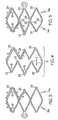
- Figures 1 and 2are rolled out views of a nested stent 10 with the stent 10 in Fig. 1 in the unexpanded state while the stent 10 in Fig. 2 is in the expanded state.
- the stent 10has five sections: two symmetrical sections 16a,b, two transitional sections 14a,b and a middle section 12.
- each section 12, 14, 16comprises at least one circumferential ring 24. It is within the scope of the invention for each section 12, 14, 16 to have one, two, three, four, five, six, seven, eight, nine, ten or more circumferential rings 24 made of a plurality of struts 18 and peaks 22.
- the stent 10also has a plurality of connectors 20.
- each of the plurality of connectors 20are peak to peak connectors 20 having the same length.
- connectors 20 engaging different sections 12, 14, 16have different lengths.
- Connectors 20engage the proximal symmetrical section 16a to the proximal transitional section 14a, the proximal transitional section 14a to the middle section 12, the middle section 12 to the distal transitional section 14b and the distal transitional section 14b to the distal symmetrical section 16b.
- connectors 20engage adjacent circumferential rings 24 within a section 12, 14, 16.
- the circumferential rings 24 in the middle section 12have struts 18 with varying lengths, as illustrated in Fig. 1-2 , 6 and the expanded view in Fig. 4 . Note that because the struts 18 are different lengths, some of the proximal/distal peaks 22 have a longitudinal position that is different from the circumferentially adjacent peak 22 so that they are longitudinally staggered and some of the proximal/distal peaks 22 are substantially circumferentially aligned with an adjacent circumferential peak 22.
- peaks 22are substantially circumferentially aligned if at least a portion of a peak 22 has the same position along the length of the stent 10, a longitudinal position, as a portion of a circumferentially adjacent peak 22 where the peaks 22 are part of the same circumferential ring 24.
- Each circumferential ring 24 of the middle section 12has the following repeating pattern of struts 18: a pair of struts 18 (a pair of struts 18 equals two struts 18), each having a length 1; is followed by a strut 18 having a length m; which is followed by a pair of struts 18, each having a length s; which is followed by a strut 18 having a length m; where 1, m, and s are different lengths.
- length 1is greater than length m which is greater than length s.
- L totalis a measure of the cumulative length of three adjacent struts with lengths s, m and 1.
- the L totalmay include some variance.
- ⁇is the longitudinal distance between the positions of adjacent circumferential peaks in a circumferential ring, as shown in Fig. 4 .
- the longitudinal distance ⁇may include some variance.
- the middle section 12has four circumferential rings 24 while the middle section 12 in Fig. 6 has two circumferential rings 24.
- two peaks 22separate circumferentially adjacent connectors 20 and that the connectors 20 engaging the same two circumferential rings 24 together are substantially circumferentially aligned.
- connectors 20are substantially circumferentially aligned if at least a portion of a connector 20 has the same position along the length of the stent 10, a longitudinal position, as a portion of a circumferentially adjacent connector 22.
- the connectors 20engage the peak 22 of the shortest pair of struts 18 in one circumferential ring 24 to the peak 22 of the longest pair of struts 18 in the longitudinally adjacent circumferential ring 24.
- the proximal and distal ends of the middle section 12are engaged to distal and proximal ends of the transitional sections 14a,b respectively.
- the distal end of the proximal transitional section 14ais engaged to the proximal end of the middle section 12 and the proximal end of the distal transitional section 14b is engaged to the distal end of the middle section 12.
- Circumferentially adjacent connectors 20 engaging the middle section 12 to either transitional section 14a,bare separated from one another by two peaks 22.
- the struts 18 forming the circumferential rings 24 of the transitional sections 14a,bhave varying lengths but the difference between the lengths is not as great as it is in the middle section 12, as is more clearly seen in Fig. 1 . Because the struts 18 are different lengths, some of the distal peaks 22 of the proximal transitional section 14a have a longitudinal position that is different from the longitudinal position of the circumferentially adjacent peak 22, so that they are longitudinally staggered, and some of the distal peaks 22 are substantially circumferentially aligned to the circumferentially adjacent peak 22. In contrast, all the proximal peaks 22 of the proximal transitional section 14a are substantially circumferentially aligned.
- proximal peaks 22 of the distal transitional section 14bhave a longitudinal position that is different from the longitudinal position of the circumferentially adjacent peak 22, i.e. longitudinally staggered, and some the proximal peaks 22 of the distal transitional section 14b substantially circumferentially aligned to the circumferential adjacent peak 22.
- all the distal peaks 22 of the distal transitional section 14bare substantially circumferentially aligned.
- the circumferential ring 24 in the proximal transitional section 14ahas the following pattern of struts 18: two pairs of struts 18 (four struts 18) having a length a, followed by one pair of struts 18 having a length b, where length a is greater than length b, (a>b).
- the circumferential ring 24 in the distal transitional section 14bhas the same pattern of struts 18: one pairs of struts 18 having a length d, followed by two pair of struts 18 having a length c, where length d is greater than length c, (d>c).
- the distal end of the proximal symmetrical section 16ais engaged to the proximal end of the proximal transitional section 14a and the proximal end of the distal symmetrical section 16b is engaged to the distal end of the distal transitional section 14b.
- all of the connectors 20 engaging the symmetrical section 16a,b to the transitional section 14a,bare substantially circumferentially aligned. This is because the peaks 22 of the transitional sections 14a,b, which are adjacent to the symmetrical sections 16a,b, are substantially circumferentially aligned.
- the proximal transitional section 14a, distal transitional section 14b and the middle section 12each have a L total .
- the L total of each sectionis the same.
- the L total of at least one sectionis different.
- the L total of the middle section 12is different than the L total of the proximal and distal transitional sections 14a,b, which are the same so that the strut lengths, length e, of the proximal and distal symmetrical sections 16a,b are the same.
- proximal peaks 22 of the struts 18 forming the proximal circumferential ring 24 of the proximal symmetrical section 16a and some of the distal peaks 22 of the struts 18 forming the distal circumferential ring 24 of the distal symmetrical section 16bhave a radiopaque (RO) marker 30.
- the radiopaque marker 30is in the form of a RO paddle.
- the radiopaque marker 30can have any form.
- the radiopaque markers 30 engaged theretoalso extend in a longitudinal direction, instead of at an oblique angle, when the stent 10 is in an expanded state.
- An oblique angleas used in this application is any angle between about 0 and about 180 degrees and includes 90 degrees.
- radiopaque markers 30Although this embodiment has a total of eight radiopaque markers 30, it is within the scope of the invention for the stent 10 to have one, two, three, four, five, six, seven, eight, nine, ten, eleven, twelve, thirteen, fourteen, fifteen, sixteen or more radiopaque markers 30. Because each radiopaque marker 30 is separated from the adjacent radiopaque marker 30 by two peaks 22, the radiopaque markers 30 are evenly distributed about the circumference of the stent 10. However, it is within the scope of the invention for the radiopaque markers 30 to be unevenly distributed about the circumference of the stent 10.
- the inventive stentsmay be made of shape memory materials such as superelastic Nitinol or spring steel, or may be made of materials which are plastically deformable.
- shape memory materialssuch as superelastic Nitinol or spring steel, or may be made of materials which are plastically deformable.
- the stentmay be provided with a memorized shape and then deformed to a reduced diameter shape. The stent may restore itself to its memorized shape upon being heated to a transition temperature and having any restraints removed therefrom.
- inventive stentsmay be created by methods including cutting or etching a design from a tubular stock, from a flat sheet which is cut or etched and which is subsequently rolled or from one or more interwoven wires or braids. Any other suitable technique which is known in the art or which is subsequently developed may also be used to manufacture the inventive stents disclosed herein.
- the delivery system or other portion of the assemblymay include one or more areas, bands, coatings, members, etc. that is (are) detectable by imaging modalities such as X-Ray, MRI, ultrasound, etc.
- imaging modalitiessuch as X-Ray, MRI, ultrasound, etc.
- at least a portion of the stent and/or adjacent assemblyis at least partially radiopaque.
- the at least a portion of the stentis configured to include one or more mechanisms for the delivery of a therapeutic agent.
- the agentwill be in the form of a coating or other layer (or layers) of material placed on a surface region of the stent, which is adapted to be released at the site of the stent's implantation or areas adjacent thereto.
- a therapeutic agentmay be a drug or other pharmaceutical product such as non-genetic agents, genetic agents, cellular material, etc.
- suitable non-genetic therapeutic agentsinclude but are not limited to: anti-thrombogenic agents such as heparin, heparin derivatives, vascular cell growth promoters, growth factor inhibitors, Paclitaxel, etc.
- an agentincludes a genetic therapeutic agent, such a genetic agent may include but is not limited to: DNA, RNA and their respective derivatives and/or components; hedgehog proteins, etc.
- the cellular materialmay include but is not limited to: cells of human origin and/or non-human origin as well as their respective components and/or derivatives thereof.
- the polymer agentmay be a polystyrene-polyisobutylene-polystyrene triblock copolymer (SIBS), polyethylene oxide, silicone rubber and/or any other suitable substrate.
- SIBSpolystyrene-polyisobutylene-polystyrene triblock copolymer
Landscapes
- Health & Medical Sciences (AREA)
- Engineering & Computer Science (AREA)
- Biomedical Technology (AREA)
- Heart & Thoracic Surgery (AREA)
- Life Sciences & Earth Sciences (AREA)
- Cardiology (AREA)
- Oral & Maxillofacial Surgery (AREA)
- Transplantation (AREA)
- Physics & Mathematics (AREA)
- Vascular Medicine (AREA)
- Optics & Photonics (AREA)
- Animal Behavior & Ethology (AREA)
- General Health & Medical Sciences (AREA)
- Public Health (AREA)
- Veterinary Medicine (AREA)
- Prostheses (AREA)
- Media Introduction/Drainage Providing Device (AREA)
Abstract
Description
- In some embodiments this invention relates to implantable medical devices, their manufacture, and methods of use.
- A stent is a medical device introduced to a body lumen and is well known in the art. Typically, a stent is implanted in a blood vessel at the site of a stenosis or aneurysm endoluminally, i.e. by so-called "minimally invasive techniques" in which the stent in a radially reduced configuration, optionally restrained in a radially compressed configuration by a sheath and/or catheter, is delivered by a stent delivery system or "introducer" to the site where it is required. The introducer may enter the body from an access location outside the body, such as through the patient's skin, or by a "cut down" technique in which the entry blood vessel is exposed by minor surgical means.
- Stents, grafts, stent-grafts, vena cava filters, expandable frameworks, and similar implantable medical devices, collectively referred to hereinafter as stents, are radially expandable endoprotheses which are typically intravascular implants capable of being implanted transluminally and enlarged radially after being introduced percutaneously. Stents may be implanted in a variety of body lumens or vessels such as within the vascular system, urinary tracts, bile ducts, fallopian tubes, coronary vessels,
- secondary vessels, etc. They may be self-expanding, expanded by an internal radial force, such as when mounted on a balloon, or a combination of self-expanding and balloon expandable (hybrid expandable).
- Stents may be created by methods including cutting or etching a design from a tubular stock, from a flat sheet which is cut or etched and which is subsequently rolled or from one or more interwoven wires or braids.
- Without limiting the scope of the invention a brief summary of some of the claimed embodiments of the invention is set forth below. Additional details of the summarized embodiments of the invention and/or additional embodiments of the invention may be found in the Detailed Description of the Invention below.
US 2004/0267353 A1 discloses a stent comprising a plurality of serpentine circumferential bands and a plurality of connector columns. Each connector columns is located between two adjacent serpentine circumferential bands and comprises a plurality connector struts. Each connector strut is connected to one end to one serpentine circumferential band and at another end to another serpentine circumferential band. Each connector column may contain multiple types of connector struts having varying circumferential spans. Each serpentine circumferential band may have sections which vary in amplitude and/or wavelength.- The problem of the invention is to provide a stent having uniform force distribution along the entire length of the stent.
- The problem is solved according to claim 1.
- In at least one embodiment, the invention is directed to a stent with a transitional section positioned between a middle section with different struts lengths and circumferentially non-aligned peaks and a symmetrical section that has equal strut lengths and circumferentially aligned peaks.
- These and other embodiments which characterize the invention are pointed out with particularity in the claims annexed hereto and forming a part hereof. However, for further understanding of the invention, its advantages and objectives obtained by its use, reference can be made to the drawings which form a further part hereof and the accompanying descriptive matter, in which there is illustrated and described an embodiments of the invention.
- A detailed description of the invention is hereafter described with specific reference being made to the drawings.
FIG. 1 is a rolled out view of a stent in the unexpanded state.FIG. 2 is a rolled out view of the stent ofFIG. 1 in the expanded state.FIG. 3 is an expanded view of a portion of the proximal end section of the stent inFIG. 2 .FIG. 4 is an expanded view of a portion of the middle section of the stent inFIG. 2 .FIG. 5 is an expanded view of a portion of the distal end section of the stent inFIG. 2 .FIG. 6 is a rolled out view of a stent in the expanded state.FIG. 7 is an expanded view of a portion of the proximal end section of the stent inFIG. 6 .FIG. 8 is an expanded view of a portion of the distal end section of the stent inFIG. 6 .- While this invention may be embodied in many different forms, there are described in detail herein specific embodiments of the invention. This description is an exemplification of the principles of the invention and is not intended to limit the invention to the particular embodiments illustrated.
- For the purposes of this disclosure, like reference numerals in the figures shall refer to like features unless otherwise indicated. As used herein, proximal and distal only identify the relative ends of the stent as shown in the figures and do not necessarily refer to the relative ends of the stent when in use.
- The
stents 10 of the instant application illustrate different means by which a nested stent pattern terminates in a symmetrical pattern. As used in this application, nested refers to stent configurations where circumferential rings have struts of varying lengths so that the peaks and troughs of a circumferential ring are longitudinally staggered, as shown inFig. 1 and described in greater detail in commonly assignedUS Patent Application Serial No. 10/269111 , entitled Stent with Improved Flexibility. Nested stents 10 that terminate in a symmetrical pattern have an expanded state where thepeaks 22 at the proximal and distal ends of thestent 10 are generally longitudinally oriented.Radiopaque markers 30 can be added to thesepeaks 22 and since thepeaks 22 are generally longitudinally oriented, theradiopaque markers 30 extend longitudinally instead of at an angle to the longitudinal axis of thestent 10. Thestents 10 of the instant application also maintain the nesting of non-fully connected segments anduniform connector 20 length between stent segments. This results in anested stent 10 with generally uniform scaffolding and generally uniform stent to lumen ratio along the longitudinal length of thestent 10.Figures 1 and2 are rolled out views of anested stent 10 with thestent 10 inFig. 1 in the unexpanded state while thestent 10 inFig. 2 is in the expanded state. Thestent 10 has five sections: twosymmetrical sections 16a,b, twotransitional sections 14a,b and amiddle section 12. As illustrated inFigs. 2 and6 , eachsection 12, 14, 16 comprises at least onecircumferential ring 24. It is within the scope of the invention for eachsection 12, 14, 16 to have one, two, three, four, five, six, seven, eight, nine, ten or morecircumferential rings 24 made of a plurality ofstruts 18 andpeaks 22.- The
stent 10 also has a plurality ofconnectors 20. In at least one embodiment, each of the plurality ofconnectors 20 are peak topeak connectors 20 having the same length. In at least one embodiment,connectors 20 engagingdifferent sections 12, 14, 16 have different lengths.Connectors 20 engage the proximalsymmetrical section 16a to the proximaltransitional section 14a, the proximaltransitional section 14a to themiddle section 12, themiddle section 12 to the distaltransitional section 14b and the distaltransitional section 14b to the distalsymmetrical section 16b. In addition,connectors 20 engage adjacentcircumferential rings 24 within asection 12, 14, 16. Although theconnectors 20 in the figures are evenly spaced about the circumference of thestent 10, it is within the scope of the invention for theconnectors 20 to be unevenly spaced about the circumference of thestent 10. - The
circumferential rings 24 in themiddle section 12 havestruts 18 with varying lengths, as illustrated inFig. 1-2 ,6 and the expanded view inFig. 4 . Note that because thestruts 18 are different lengths, some of the proximal/distal peaks 22 have a longitudinal position that is different from the circumferentiallyadjacent peak 22 so that they are longitudinally staggered and some of the proximal/distal peaks 22 are substantially circumferentially aligned with an adjacentcircumferential peak 22. As used in this application,peaks 22 are substantially circumferentially aligned if at least a portion of apeak 22 has the same position along the length of thestent 10, a longitudinal position, as a portion of a circumferentiallyadjacent peak 22 where thepeaks 22 are part of the samecircumferential ring 24. - Each
circumferential ring 24 of themiddle section 12 has the following repeating pattern of struts 18: a pair of struts 18 (a pair ofstruts 18 equals two struts 18), each having a length 1; is followed by astrut 18 having a length m; which is followed by a pair ofstruts 18, each having a length s; which is followed by astrut 18 having a length m; where 1, m, and s are different lengths. - In at least one embodiment, length 1 is greater than length m which is greater than length s. The
middle section 12 can be described mathematically as Ltotal = s+m+1 and m-s = l-m = δ. Ltotal is a measure of the cumulative length of three adjacent struts with lengths s, m and 1. In some embodiments, the Ltotal may include some variance. δ is the longitudinal distance between the positions of adjacent circumferential peaks in a circumferential ring, as shown inFig. 4 . In some embodiments, the longitudinal distance δ may include some variance. - In
Figs. 1-2 , themiddle section 12 has fourcircumferential rings 24 while themiddle section 12 inFig. 6 has two circumferential rings 24. Note that twopeaks 22 separate circumferentiallyadjacent connectors 20 and that theconnectors 20 engaging the same twocircumferential rings 24 together are substantially circumferentially aligned. As used in this application,connectors 20 are substantially circumferentially aligned if at least a portion of aconnector 20 has the same position along the length of thestent 10, a longitudinal position, as a portion of a circumferentiallyadjacent connector 22. Theconnectors 20 engage thepeak 22 of the shortest pair ofstruts 18 in onecircumferential ring 24 to thepeak 22 of the longest pair ofstruts 18 in the longitudinally adjacentcircumferential ring 24. - The proximal and distal ends of the
middle section 12 are engaged to distal and proximal ends of thetransitional sections 14a,b respectively. Thus, the distal end of the proximaltransitional section 14a is engaged to the proximal end of themiddle section 12 and the proximal end of the distaltransitional section 14b is engaged to the distal end of themiddle section 12. Circumferentiallyadjacent connectors 20 engaging themiddle section 12 to eithertransitional section 14a,b are separated from one another by twopeaks 22. - Similar to the
middle section 12, thestruts 18 forming the circumferential rings 24 of thetransitional sections 14a,b have varying lengths but the difference between the lengths is not as great as it is in themiddle section 12, as is more clearly seen inFig. 1 . Because thestruts 18 are different lengths, some of thedistal peaks 22 of the proximaltransitional section 14a have a longitudinal position that is different from the longitudinal position of the circumferentiallyadjacent peak 22, so that they are longitudinally staggered, and some of thedistal peaks 22 are substantially circumferentially aligned to the circumferentiallyadjacent peak 22. In contrast, all theproximal peaks 22 of the proximaltransitional section 14a are substantially circumferentially aligned. Similarly, some of theproximal peaks 22 of the distaltransitional section 14b have a longitudinal position that is different from the longitudinal position of the circumferentiallyadjacent peak 22, i.e. longitudinally staggered, and some theproximal peaks 22 of the distaltransitional section 14b substantially circumferentially aligned to the circumferentialadjacent peak 22. In addition, all thedistal peaks 22 of the distaltransitional section 14b are substantially circumferentially aligned. - As shown in
Figs. 2 and6 , and in the expanded portions of thestent 10 shown inFigs. 3, 5 , and7-8 , thecircumferential ring 24 in the proximaltransitional section 14a has the following pattern of struts 18: two pairs of struts 18 (four struts 18) having a length a, followed by one pair ofstruts 18 having a length b, where length a is greater than length b, (a>b). The proximaltransitional end section 14a can be described mathematically as Ltotal = 2a+b and a-b = δ. Thecircumferential ring 24 in the distaltransitional section 14b has the same pattern of struts 18: one pairs ofstruts 18 having a length d, followed by two pair ofstruts 18 having a length c, where length d is greater than length c, (d>c). The distaltransitional section 14b of the nestedstent 10 can be described mathematically as Ltotal = 2c+d and d-c = δ. In at least one embodiment, the Ltotal of the proximaltransitional section 14a, the Ltotal of themiddle section 12 and the Ltotal of the distaltransitional section 14b are equal to one another. - As shown in
Figs. 2 and6 , for example, the distal end of the proximalsymmetrical section 16a is engaged to the proximal end of the proximaltransitional section 14a and the proximal end of the distalsymmetrical section 16b is engaged to the distal end of the distaltransitional section 14b. Note that all of theconnectors 20 engaging thesymmetrical section 16a,b to thetransitional section 14a,b, are substantially circumferentially aligned. This is because thepeaks 22 of thetransitional sections 14a,b, which are adjacent to thesymmetrical sections 16a,b, are substantially circumferentially aligned. Also note that, in this embodiment, there is a one to one relationship between the number ofconnectors 20 and thepeaks 22 of both thesymmetrical section 16a,b and thetransitional section 14a,b, unlike the relationship between the number ofconnectors 20 andpeaks 22 between thetransitional section 14a,b and themiddle section 12. However, it is within the scope of the invention to have any ratio of peaks and connectors. - The circumferential rings 24 forming the
symmetrical sections 16a,b are the outermost circumferential rings 24 of thestent 10. As shown inFigs. 1-2 ,6 and expanded portions shown inFigs. 3, 5 ,7-8 , thestruts 18 of thesymmetrical sections 16a,b all have the same length, length e. Length e can be described mathematically as e = Ltotal/3. InFig. 2 , thesymmetrical sections 16a,b only have onecircumferential ring 24 whereas inFig. 6 , thesymmetrical sections 16a,b each have two circumferential rings 24. - As discussed above, the proximal
transitional section 14a, distaltransitional section 14b and themiddle section 12 each have a Ltotal. In one embodiment, the Ltotal of each section is the same. Thus, in this embodiment, 2a+b = s+m+1 = 2c+d. In at least one embodiment, the Ltotal of at least one section is different. In one embodiment, the Ltotal of themiddle section 12 is different than the Ltotal of the proximal and distaltransitional sections 14a,b, which are the same so that the strut lengths, length e, of the proximal and distalsymmetrical sections 16a,b are the same. - Note that some of the
proximal peaks 22 of thestruts 18 forming the proximalcircumferential ring 24 of the proximalsymmetrical section 16a and some of thedistal peaks 22 of thestruts 18 forming the distalcircumferential ring 24 of the distalsymmetrical section 16b have a radiopaque (RO)marker 30. In this embodiment, theradiopaque marker 30 is in the form of a RO paddle. However, theradiopaque marker 30 can have any form. Because the proximal/distal peaks 22 extend longitudinally when thestent 10 is in an expanded state, theradiopaque markers 30 engaged thereto also extend in a longitudinal direction, instead of at an oblique angle, when thestent 10 is in an expanded state. An oblique angle, as used in this application is any angle between about 0 and about 180 degrees and includes 90 degrees. - Although this embodiment has a total of eight
radiopaque markers 30, it is within the scope of the invention for thestent 10 to have one, two, three, four, five, six, seven, eight, nine, ten, eleven, twelve, thirteen, fourteen, fifteen, sixteen or moreradiopaque markers 30. Because eachradiopaque marker 30 is separated from the adjacentradiopaque marker 30 by twopeaks 22, theradiopaque markers 30 are evenly distributed about the circumference of thestent 10. However, it is within the scope of the invention for theradiopaque markers 30 to be unevenly distributed about the circumference of thestent 10. - The inventive stents may be made of shape memory materials such as superelastic Nitinol or spring steel, or may be made of materials which are plastically deformable. In the case of shape memory materials, the stent may be provided with a memorized shape and then deformed to a reduced diameter shape. The stent may restore itself to its memorized shape upon being heated to a transition temperature and having any restraints removed therefrom.
- The inventive stents may be created by methods including cutting or etching a design from a tubular stock, from a flat sheet which is cut or etched and which is subsequently rolled or from one or more interwoven wires or braids. Any other suitable technique which is known in the art or which is subsequently developed may also be used to manufacture the inventive stents disclosed herein.
- In addition to or instead of the use of RO paddles, the delivery system or other portion of the assembly may include one or more areas, bands, coatings, members, etc. that is (are) detectable by imaging modalities such as X-Ray, MRI, ultrasound, etc. In some embodiments at least a portion of the stent and/or adjacent assembly is at least partially radiopaque.
- In some embodiments the at least a portion of the stent is configured to include one or more mechanisms for the delivery of a therapeutic agent. Often the agent will be in the form of a coating or other layer (or layers) of material placed on a surface region of the stent, which is adapted to be released at the site of the stent's implantation or areas adjacent thereto.
- A therapeutic agent may be a drug or other pharmaceutical product such as non-genetic agents, genetic agents, cellular material, etc. Some examples of suitable non-genetic therapeutic agents include but are not limited to: anti-thrombogenic agents such as heparin, heparin derivatives, vascular cell growth promoters, growth factor inhibitors, Paclitaxel, etc. Where an agent includes a genetic therapeutic agent, such a genetic agent may include but is not limited to: DNA, RNA and their respective derivatives and/or components; hedgehog proteins, etc. Where a therapeutic agent includes cellular material, the cellular material may include but is not limited to: cells of human origin and/or non-human origin as well as their respective components and/or derivatives thereof. Where the therapeutic agent includes a polymer agent, the polymer agent may be a polystyrene-polyisobutylene-polystyrene triblock copolymer (SIBS), polyethylene oxide, silicone rubber and/or any other suitable substrate.
- The above disclosure is intended to be illustrative and not' exhaustive. This description will suggest many variations and alternatives to one of ordinary skill in this art. All these alternatives and variations are intended to be included within the scope of the claims where the term "comprising" means "including, but not limited to".
Claims (12)
- A stent, the stent comprising:a symmetrical section (16), the symmetrical section comprising a first circumferential ring, the first circumferential ring comprising a plurality of first end struts, the plurality of first end struts each having a first end length;a transitional section (14), the transitional section comprising a first circumferential ring, the first circumferential ring comprising a plurality of transitional struts, the plurality of transitional struts comprising a first transitional strut and a second transitional strut, the first transitional strut having a first transitional length, the second transitional strut having a second transitional length, different from the length of said first transitional strut;a plurality of first connectors, the plurality of first connectors engaging the symmetrical section and the transitional section, the plurality of first connectors being substantially circumferentially aligned when the stent is in an unexpanded state; anda middle section (12), the middle section comprising a first circumferential ring, the first circumferential ring comprising a plurality of middle struts, the plurality of middle struts comprising a first middle strut, a second middle strut and a third middle strut, the first middle strut having a first middle length, the second middle strut having a second middle length different from the length of said first middle strut and the third middle strut having a third middle length different from the lengths of said first and second middle strut.
- The stent of claim 1 further comprising at least one radiopaque marker.
- The stent of claim 2, the first circumferential ring of the symmetrical section further comprising a plurality of proximal peaks, the at least one radiopaque marker being engaged to at least one of the plurality of proximal peaks.
- The stent of claim 3, the radiopaque marker being in the form of a radiopaque paddle.
- The stent of claim 4, the radiopaque paddle extending in a longitudinal direction when the stent is in an expanded state.
- The stent of claim 1, wherein the symmentrical section, the transitional section and the middle section define a tubular body, the tubular body having a diameter at the first, second and third sections, the diameter being the same for each section.
- The stent of claim 1, the first circumferential ring of the symmetrical section having a plurality of distal peaks, the first circumferential ring of the transitional section having a plurality of proximal peaks, the number of peaks forming the plurality of distal peaks the same as the number of peaks forming the plurality of proximal peaks, the plurality of first connectors engaging the distal peaks of the first circumferential ring of the symmetrical section and the proximal peaks of the first circumferential ring of the transitional section.
- The stent of claim 1, further comprising a plurality of second connectors, the plurality of second connectors engaging the transitional section to the middle section.
- The stent of claim 8, the plurality of second connectors being peak to peak connectors.
- The stent of claim 9, the plurality of first and second connectors having the same length.
- The stent of claim 8, the number of connectors comprising the plurality of first connectors greater than the number of connectors comprising the plurality of second connectors.
- The stent of claim 1, the first circumferential ring of the transitional section having a total length equal to two times the sum of the first transitional length plus the second transitional length; the first circumferential ring of the third section having a total length equal to the first middle length plus the sum of the second middle length plus the third middle length, the total length of the first circumferential ring of the transitional section being equal to the total length of the first circumferential ring of the third section, and the first end length equal to one third the total length.
Applications Claiming Priority (3)
| Application Number | Priority Date | Filing Date | Title |
|---|---|---|---|
| US84311406P | 2006-09-08 | 2006-09-08 | |
| US11/650,050US8414637B2 (en) | 2006-09-08 | 2007-01-05 | Stent |
| PCT/US2007/015296WO2008030291A1 (en) | 2006-09-08 | 2007-07-10 | Stent having end section with constant strut lengths, transitional section and middle section with variable strut lengths |
Publications (2)
| Publication Number | Publication Date |
|---|---|
| EP2063809A1 EP2063809A1 (en) | 2009-06-03 |
| EP2063809B1true EP2063809B1 (en) | 2011-09-07 |
Family
ID=38814542
Family Applications (1)
| Application Number | Title | Priority Date | Filing Date |
|---|---|---|---|
| EP07810122ANot-in-forceEP2063809B1 (en) | 2006-09-08 | 2007-07-10 | Stent having end section with constant strut lengths, transitional section and middle section with variable strut lengths |
Country Status (4)
| Country | Link |
|---|---|
| US (1) | US8414637B2 (en) |
| EP (1) | EP2063809B1 (en) |
| AT (1) | ATE523163T1 (en) |
| WO (1) | WO2008030291A1 (en) |
Families Citing this family (16)
| Publication number | Priority date | Publication date | Assignee | Title |
|---|---|---|---|---|
| US8128677B2 (en) | 2007-12-12 | 2012-03-06 | Intact Vascular LLC | Device and method for tacking plaque to a blood vessel wall |
| US10716573B2 (en) | 2008-05-01 | 2020-07-21 | Aneuclose | Janjua aneurysm net with a resilient neck-bridging portion for occluding a cerebral aneurysm |
| US10028747B2 (en) | 2008-05-01 | 2018-07-24 | Aneuclose Llc | Coils with a series of proximally-and-distally-connected loops for occluding a cerebral aneurysm |
| EP2416746B1 (en)* | 2009-04-10 | 2017-06-21 | Covidien LP | Implants having high fatigue resistance |
| US8221489B2 (en) | 2009-08-20 | 2012-07-17 | Stentys | Device and method for treating a body lumen |
| US9358140B1 (en) | 2009-11-18 | 2016-06-07 | Aneuclose Llc | Stent with outer member to embolize an aneurysm |
| EP2667828A4 (en)* | 2011-01-27 | 2016-01-13 | Orbusneich Medical Inc | Medical device for implantation into luminal structures |
| WO2014186435A2 (en) | 2013-05-14 | 2014-11-20 | University Of Georgia Research Foundation, Inc. | Compositions and methods for reducing neointima formation |
| EP3137054B1 (en) | 2014-05-02 | 2021-07-07 | Research Institute at Nationwide Children's Hospital | Compositions and methods for anti-lyst immunomodulation |
| US9433520B2 (en) | 2015-01-29 | 2016-09-06 | Intact Vascular, Inc. | Delivery device and method of delivery |
| US9375336B1 (en) | 2015-01-29 | 2016-06-28 | Intact Vascular, Inc. | Delivery device and method of delivery |
| US11285211B2 (en) | 2015-04-01 | 2022-03-29 | Yale University | Iron platinum particles for adherence of biologics on medical implants |
| CN108601863A (en) | 2015-12-11 | 2018-09-28 | 国家儿童医院研究所 | The system and method for patient-specific tissue engineering blood vessel graft for optimization |
| US10993824B2 (en) | 2016-01-01 | 2021-05-04 | Intact Vascular, Inc. | Delivery device and method of delivery |
| US10517747B2 (en) | 2017-06-19 | 2019-12-31 | Cook Medical Technologies Llc | Cannula cut stent with closed end cell geometry |
| US11660218B2 (en) | 2017-07-26 | 2023-05-30 | Intact Vascular, Inc. | Delivery device and method of delivery |
Family Cites Families (63)
| Publication number | Priority date | Publication date | Assignee | Title |
|---|---|---|---|---|
| US6464722B2 (en) | 1994-03-17 | 2002-10-15 | Medinol, Ltd. | Flexible expandable stent |
| DE69528216T2 (en) | 1994-06-17 | 2003-04-17 | Terumo K.K., Tokio/Tokyo | Process for the production of a permanent stent |
| US6331188B1 (en) | 1994-08-31 | 2001-12-18 | Gore Enterprise Holdings, Inc. | Exterior supported self-expanding stent-graft |
| US5755770A (en) | 1995-01-31 | 1998-05-26 | Boston Scientific Corporatiion | Endovascular aortic graft |
| US7204848B1 (en) | 1995-03-01 | 2007-04-17 | Boston Scientific Scimed, Inc. | Longitudinally flexible expandable stent |
| DE69622231T2 (en) | 1995-03-01 | 2002-12-05 | Scimed Life Systems, Inc. | LENGTHFLEXIBLE AND EXPANDABLE STENT |
| ES2119527T5 (en) | 1995-04-01 | 2006-11-16 | Variomed Ag | STENT DEVICE FOR TRANSLUMINAL IMPLEMENTATION IN HOLLOW ORGANS. |
| US5776161A (en) | 1995-10-16 | 1998-07-07 | Instent, Inc. | Medical stents, apparatus and method for making same |
| US6334871B1 (en) | 1996-03-13 | 2002-01-01 | Medtronic, Inc. | Radiopaque stent markers |
| IL117472A0 (en) | 1996-03-13 | 1996-07-23 | Instent Israel Ltd | Radiopaque stent markers |
| DE19614160A1 (en) | 1996-04-10 | 1997-10-16 | Variomed Ag | Stent for transluminal implantation in hollow organs |
| US5922021A (en) | 1996-04-26 | 1999-07-13 | Jang; G. David | Intravascular stent |
| JP3009848B2 (en)* | 1996-06-11 | 2000-02-14 | 住友重機械工業株式会社 | Inner roller and outer roller of internal meshing planetary gear structure and method of manufacturing the same |
| US5922020A (en) | 1996-08-02 | 1999-07-13 | Localmed, Inc. | Tubular prosthesis having improved expansion and imaging characteristics |
| US5824046A (en) | 1996-09-27 | 1998-10-20 | Scimed Life Systems, Inc. | Covered stent |
| US6432127B1 (en) | 1996-10-11 | 2002-08-13 | Transvascular, Inc. | Devices for forming and/or maintaining connections between adjacent anatomical conduits |
| US5775770A (en)* | 1996-11-25 | 1998-07-07 | Tunney; John P. | Portable baby carrier |
| DE69739287D1 (en)* | 1996-12-20 | 2009-04-16 | Panasonic Corp | OPTICAL RECORDING METHOD AND OPTICAL RECORDING DEVICE |
| US5858556A (en) | 1997-01-21 | 1999-01-12 | Uti Corporation | Multilayer composite tubular structure and method of making |
| DE29702671U1 (en) | 1997-02-17 | 1997-04-10 | Jomed Implantate GmbH, 72414 Rangendingen | Stent |
| US5741327A (en) | 1997-05-06 | 1998-04-21 | Global Therapeutics, Inc. | Surgical stent featuring radiopaque markers |
| US6272370B1 (en) | 1998-08-07 | 2001-08-07 | The Regents Of University Of Minnesota | MR-visible medical device for neurological interventions using nonlinear magnetic stereotaxis and a method imaging |
| US6340367B1 (en) | 1997-08-01 | 2002-01-22 | Boston Scientific Scimed, Inc. | Radiopaque markers and methods of using the same |
| JP4292710B2 (en) | 1997-09-24 | 2009-07-08 | エム イー ディ インスチィチュート インク | Radially expandable stent |
| US6042606A (en) | 1997-09-29 | 2000-03-28 | Cook Incorporated | Radially expandable non-axially contracting surgical stent |
| DE19746735C2 (en) | 1997-10-13 | 2003-11-06 | Simag Gmbh Systeme Und Instr F | NMR imaging method for the display, position determination or functional control of a device inserted into an examination object and device for use in such a method |
| AUPP083597A0 (en) | 1997-12-10 | 1998-01-08 | William A Cook Australia Pty Ltd | Endoluminal aortic stents |
| US6022374A (en) | 1997-12-16 | 2000-02-08 | Cardiovasc, Inc. | Expandable stent having radiopaque marker and method |
| US6503271B2 (en) | 1998-01-09 | 2003-01-07 | Cordis Corporation | Intravascular device with improved radiopacity |
| AU2579999A (en) | 1998-02-03 | 1999-08-16 | Cardiovascular Interventional Systems, Inc. | Tubular stent consists of non-parallel expansion struts and contralaterally attached diagonal connectors |
| US6113627A (en) | 1998-02-03 | 2000-09-05 | Jang; G. David | Tubular stent consists of horizontal expansion struts and contralaterally attached diagonal-connectors |
| US6558415B2 (en) | 1998-03-27 | 2003-05-06 | Intratherapeutics, Inc. | Stent |
| US6626938B1 (en) | 2000-11-16 | 2003-09-30 | Cordis Corporation | Stent graft having a pleated graft member |
| US6524336B1 (en)* | 1998-04-09 | 2003-02-25 | Cook Incorporated | Endovascular graft |
| US6361759B1 (en) | 1998-05-26 | 2002-03-26 | Wisconsin Alumni Research Foundation | MR signal-emitting coatings |
| US8092514B1 (en) | 1998-11-16 | 2012-01-10 | Boston Scientific Scimed, Inc. | Stretchable anti-buckling coiled-sheet stent |
| US6340366B2 (en) | 1998-12-08 | 2002-01-22 | Bandula Wijay | Stent with nested or overlapping rings |
| US6361557B1 (en) | 1999-02-05 | 2002-03-26 | Medtronic Ave, Inc. | Staplebutton radiopaque marker |
| US6730116B1 (en) | 1999-04-16 | 2004-05-04 | Medtronic, Inc. | Medical device for intraluminal endovascular stenting |
| US6273911B1 (en) | 1999-04-22 | 2001-08-14 | Advanced Cardiovascular Systems, Inc. | Variable strength stent |
| US6368346B1 (en) | 1999-06-03 | 2002-04-09 | American Medical Systems, Inc. | Bioresorbable stent |
| US6379381B1 (en) | 1999-09-03 | 2002-04-30 | Advanced Cardiovascular Systems, Inc. | Porous prosthesis and a method of depositing substances into the pores |
| WO2001021095A2 (en)* | 1999-09-23 | 2001-03-29 | Advanced Stent Technologies, Inc. | Bifurcation stent system and method |
| US6331189B1 (en) | 1999-10-18 | 2001-12-18 | Medtronic, Inc. | Flexible medical stent |
| US6355058B1 (en) | 1999-12-30 | 2002-03-12 | Advanced Cardiovascular Systems, Inc. | Stent with radiopaque coating consisting of particles in a binder |
| US6423090B1 (en) | 2000-02-11 | 2002-07-23 | Advanced Cardiovascular Systems, Inc. | Stent pattern with staged expansion |
| US7828835B2 (en) | 2000-03-01 | 2010-11-09 | Medinol Ltd. | Longitudinally flexible stent |
| US6652579B1 (en) | 2000-06-22 | 2003-11-25 | Advanced Cardiovascular Systems, Inc. | Radiopaque stent |
| US8070792B2 (en) | 2000-09-22 | 2011-12-06 | Boston Scientific Scimed, Inc. | Stent |
| US6623518B2 (en) | 2001-02-26 | 2003-09-23 | Ev3 Peripheral, Inc. | Implant delivery system with interlock |
| US8197535B2 (en) | 2001-06-19 | 2012-06-12 | Cordis Corporation | Low profile improved radiopacity intraluminal medical device |
| US20040111147A1 (en) | 2002-12-03 | 2004-06-10 | Rabkin Dmitry J. | Temporary, repositionable or retrievable intraluminal devices |
| US20030176914A1 (en) | 2003-01-21 | 2003-09-18 | Rabkin Dmitry J. | Multi-segment modular stent and methods for manufacturing stents |
| JP4512369B2 (en) | 2002-01-31 | 2010-07-28 | ラディ・メディカル・システムズ・アクチェボラーグ | Stent |
| US20030225448A1 (en) | 2002-05-28 | 2003-12-04 | Scimed Life Systems, Inc. | Polar radiopaque marker for stent |
| US7331986B2 (en) | 2002-10-09 | 2008-02-19 | Boston Scientific Scimed, Inc. | Intraluminal medical device having improved visibility |
| US7223283B2 (en)* | 2002-10-09 | 2007-05-29 | Boston Scientific Scimed, Inc. | Stent with improved flexibility |
| US20040088039A1 (en) | 2002-11-01 | 2004-05-06 | Lee Nathan T. | Method of securing radiopaque markers to an implant |
| US7131993B2 (en) | 2003-06-25 | 2006-11-07 | Boston Scientific Scimed, Inc. | Varying circumferential spanned connectors in a stent |
| US20050060025A1 (en) | 2003-09-12 | 2005-03-17 | Mackiewicz David A. | Radiopaque markers for medical devices |
| US20050149168A1 (en) | 2003-12-30 | 2005-07-07 | Daniel Gregorich | Stent to be deployed on a bend |
| US7243408B2 (en)* | 2004-02-09 | 2007-07-17 | Boston Scientific Scimed, Inc. | Process method for attaching radio opaque markers to shape memory stent |
| US7758892B1 (en) | 2004-05-20 | 2010-07-20 | Boston Scientific Scimed, Inc. | Medical devices having multiple layers |
- 2007
- 2007-01-05USUS11/650,050patent/US8414637B2/ennot_activeExpired - Fee Related
- 2007-07-10EPEP07810122Apatent/EP2063809B1/ennot_activeNot-in-force
- 2007-07-10ATAT07810122Tpatent/ATE523163T1/ennot_activeIP Right Cessation
- 2007-07-10WOPCT/US2007/015296patent/WO2008030291A1/enactiveApplication Filing
Also Published As
| Publication number | Publication date |
|---|---|
| US20080065193A1 (en) | 2008-03-13 |
| ATE523163T1 (en) | 2011-09-15 |
| EP2063809A1 (en) | 2009-06-03 |
| WO2008030291A1 (en) | 2008-03-13 |
| US8414637B2 (en) | 2013-04-09 |
Similar Documents
| Publication | Publication Date | Title |
|---|---|---|
| EP2063809B1 (en) | Stent having end section with constant strut lengths, transitional section and middle section with variable strut lengths | |
| EP2059199B1 (en) | Longitudinally flexible expandable stent | |
| US8211163B2 (en) | Hybrid symmetrical stent designs | |
| US8236044B2 (en) | Stent design with variable expansion columns along circumference | |
| EP3119354B1 (en) | Reduced granulation and inflammation stent design | |
| US8348993B2 (en) | Flexible stent design | |
| US7988720B2 (en) | Longitudinally flexible expandable stent | |
| EP2124848B1 (en) | Stent design with struts of various angles and stiffness | |
| EP2068762B1 (en) | Intra-columnar cell features to improve drug distribution and scaffolding of a stent | |
| EP2086475B1 (en) | Bifurcated stent | |
| US20080065197A1 (en) | Bifurcated Stent | |
| US20070208411A1 (en) | Bifurcated stent with surface area gradient | |
| EP2073766B1 (en) | Bifurcated stent with entire circumferential petal |
Legal Events
| Date | Code | Title | Description |
|---|---|---|---|
| PUAI | Public reference made under article 153(3) epc to a published international application that has entered the european phase | Free format text:ORIGINAL CODE: 0009012 | |
| 17P | Request for examination filed | Effective date:20090326 | |
| AK | Designated contracting states | Kind code of ref document:A1 Designated state(s):AT BE BG CH CY CZ DE DK EE ES FI FR GB GR HU IE IS IT LI LT LU LV MC MT NL PL PT RO SE SI SK TR | |
| AX | Request for extension of the european patent | Extension state:AL BA HR MK RS | |
| 17Q | First examination report despatched | Effective date:20090902 | |
| GRAP | Despatch of communication of intention to grant a patent | Free format text:ORIGINAL CODE: EPIDOSNIGR1 | |
| RTI1 | Title (correction) | Free format text:STENT HAVING END SECTION WITH CONSTANT STRUT LENGTHS, TRANSITIONAL SECTION AND MIDDLE SECTION WITH VARIABLE STRUT LENGTHS | |
| GRAS | Grant fee paid | Free format text:ORIGINAL CODE: EPIDOSNIGR3 | |
| GRAA | (expected) grant | Free format text:ORIGINAL CODE: 0009210 | |
| REG | Reference to a national code | Ref country code:GB Ref legal event code:FG4D | |
| REG | Reference to a national code | Ref country code:CH Ref legal event code:EP | |
| REG | Reference to a national code | Ref country code:IE Ref legal event code:FG4D | |
| REG | Reference to a national code | Ref country code:DE Ref legal event code:R096 Ref document number:602007017041 Country of ref document:DE Effective date:20111103 | |
| REG | Reference to a national code | Ref country code:NL Ref legal event code:VDEP Effective date:20110907 | |
| PG25 | Lapsed in a contracting state [announced via postgrant information from national office to epo] | Ref country code:FI Free format text:LAPSE BECAUSE OF FAILURE TO SUBMIT A TRANSLATION OF THE DESCRIPTION OR TO PAY THE FEE WITHIN THE PRESCRIBED TIME-LIMIT Effective date:20110907 Ref country code:LT Free format text:LAPSE BECAUSE OF FAILURE TO SUBMIT A TRANSLATION OF THE DESCRIPTION OR TO PAY THE FEE WITHIN THE PRESCRIBED TIME-LIMIT Effective date:20110907 Ref country code:SE Free format text:LAPSE BECAUSE OF FAILURE TO SUBMIT A TRANSLATION OF THE DESCRIPTION OR TO PAY THE FEE WITHIN THE PRESCRIBED TIME-LIMIT Effective date:20110907 | |
| LTIE | Lt: invalidation of european patent or patent extension | Effective date:20110907 | |
| PG25 | Lapsed in a contracting state [announced via postgrant information from national office to epo] | Ref country code:CY Free format text:LAPSE BECAUSE OF FAILURE TO SUBMIT A TRANSLATION OF THE DESCRIPTION OR TO PAY THE FEE WITHIN THE PRESCRIBED TIME-LIMIT Effective date:20110907 Ref country code:GR Free format text:LAPSE BECAUSE OF FAILURE TO SUBMIT A TRANSLATION OF THE DESCRIPTION OR TO PAY THE FEE WITHIN THE PRESCRIBED TIME-LIMIT Effective date:20111208 Ref country code:SI Free format text:LAPSE BECAUSE OF FAILURE TO SUBMIT A TRANSLATION OF THE DESCRIPTION OR TO PAY THE FEE WITHIN THE PRESCRIBED TIME-LIMIT Effective date:20110907 Ref country code:LV Free format text:LAPSE BECAUSE OF FAILURE TO SUBMIT A TRANSLATION OF THE DESCRIPTION OR TO PAY THE FEE WITHIN THE PRESCRIBED TIME-LIMIT Effective date:20110907 Ref country code:AT Free format text:LAPSE BECAUSE OF FAILURE TO SUBMIT A TRANSLATION OF THE DESCRIPTION OR TO PAY THE FEE WITHIN THE PRESCRIBED TIME-LIMIT Effective date:20110907 | |
| REG | Reference to a national code | Ref country code:AT Ref legal event code:MK05 Ref document number:523163 Country of ref document:AT Kind code of ref document:T Effective date:20110907 | |
| PG25 | Lapsed in a contracting state [announced via postgrant information from national office to epo] | Ref country code:BE Free format text:LAPSE BECAUSE OF FAILURE TO SUBMIT A TRANSLATION OF THE DESCRIPTION OR TO PAY THE FEE WITHIN THE PRESCRIBED TIME-LIMIT Effective date:20110907 | |
| PG25 | Lapsed in a contracting state [announced via postgrant information from national office to epo] | Ref country code:CZ Free format text:LAPSE BECAUSE OF FAILURE TO SUBMIT A TRANSLATION OF THE DESCRIPTION OR TO PAY THE FEE WITHIN THE PRESCRIBED TIME-LIMIT Effective date:20110907 Ref country code:SK Free format text:LAPSE BECAUSE OF FAILURE TO SUBMIT A TRANSLATION OF THE DESCRIPTION OR TO PAY THE FEE WITHIN THE PRESCRIBED TIME-LIMIT Effective date:20110907 Ref country code:IS Free format text:LAPSE BECAUSE OF FAILURE TO SUBMIT A TRANSLATION OF THE DESCRIPTION OR TO PAY THE FEE WITHIN THE PRESCRIBED TIME-LIMIT Effective date:20120107 | |
| PG25 | Lapsed in a contracting state [announced via postgrant information from national office to epo] | Ref country code:NL Free format text:LAPSE BECAUSE OF FAILURE TO SUBMIT A TRANSLATION OF THE DESCRIPTION OR TO PAY THE FEE WITHIN THE PRESCRIBED TIME-LIMIT Effective date:20110907 Ref country code:PT Free format text:LAPSE BECAUSE OF FAILURE TO SUBMIT A TRANSLATION OF THE DESCRIPTION OR TO PAY THE FEE WITHIN THE PRESCRIBED TIME-LIMIT Effective date:20120109 Ref country code:EE Free format text:LAPSE BECAUSE OF FAILURE TO SUBMIT A TRANSLATION OF THE DESCRIPTION OR TO PAY THE FEE WITHIN THE PRESCRIBED TIME-LIMIT Effective date:20110907 Ref country code:RO Free format text:LAPSE BECAUSE OF FAILURE TO SUBMIT A TRANSLATION OF THE DESCRIPTION OR TO PAY THE FEE WITHIN THE PRESCRIBED TIME-LIMIT Effective date:20110907 Ref country code:PL Free format text:LAPSE BECAUSE OF FAILURE TO SUBMIT A TRANSLATION OF THE DESCRIPTION OR TO PAY THE FEE WITHIN THE PRESCRIBED TIME-LIMIT Effective date:20110907 | |
| PLBE | No opposition filed within time limit | Free format text:ORIGINAL CODE: 0009261 | |
| STAA | Information on the status of an ep patent application or granted ep patent | Free format text:STATUS: NO OPPOSITION FILED WITHIN TIME LIMIT | |
| PG25 | Lapsed in a contracting state [announced via postgrant information from national office to epo] | Ref country code:DK Free format text:LAPSE BECAUSE OF FAILURE TO SUBMIT A TRANSLATION OF THE DESCRIPTION OR TO PAY THE FEE WITHIN THE PRESCRIBED TIME-LIMIT Effective date:20110907 | |
| 26N | No opposition filed | Effective date:20120611 | |
| REG | Reference to a national code | Ref country code:DE Ref legal event code:R097 Ref document number:602007017041 Country of ref document:DE Effective date:20120611 | |
| PG25 | Lapsed in a contracting state [announced via postgrant information from national office to epo] | Ref country code:MC Free format text:LAPSE BECAUSE OF NON-PAYMENT OF DUE FEES Effective date:20120731 | |
| REG | Reference to a national code | Ref country code:CH Ref legal event code:PL | |
| GBPC | Gb: european patent ceased through non-payment of renewal fee | Effective date:20120710 | |
| PG25 | Lapsed in a contracting state [announced via postgrant information from national office to epo] | Ref country code:CH Free format text:LAPSE BECAUSE OF NON-PAYMENT OF DUE FEES Effective date:20120731 Ref country code:ES Free format text:LAPSE BECAUSE OF FAILURE TO SUBMIT A TRANSLATION OF THE DESCRIPTION OR TO PAY THE FEE WITHIN THE PRESCRIBED TIME-LIMIT Effective date:20111218 Ref country code:GB Free format text:LAPSE BECAUSE OF NON-PAYMENT OF DUE FEES Effective date:20120710 Ref country code:LI Free format text:LAPSE BECAUSE OF NON-PAYMENT OF DUE FEES Effective date:20120731 | |
| PG25 | Lapsed in a contracting state [announced via postgrant information from national office to epo] | Ref country code:IT Free format text:LAPSE BECAUSE OF NON-PAYMENT OF DUE FEES Effective date:20120710 | |
| PG25 | Lapsed in a contracting state [announced via postgrant information from national office to epo] | Ref country code:BG Free format text:LAPSE BECAUSE OF FAILURE TO SUBMIT A TRANSLATION OF THE DESCRIPTION OR TO PAY THE FEE WITHIN THE PRESCRIBED TIME-LIMIT Effective date:20111207 | |
| PG25 | Lapsed in a contracting state [announced via postgrant information from national office to epo] | Ref country code:MT Free format text:LAPSE BECAUSE OF FAILURE TO SUBMIT A TRANSLATION OF THE DESCRIPTION OR TO PAY THE FEE WITHIN THE PRESCRIBED TIME-LIMIT Effective date:20110907 | |
| PG25 | Lapsed in a contracting state [announced via postgrant information from national office to epo] | Ref country code:TR Free format text:LAPSE BECAUSE OF FAILURE TO SUBMIT A TRANSLATION OF THE DESCRIPTION OR TO PAY THE FEE WITHIN THE PRESCRIBED TIME-LIMIT Effective date:20110907 | |
| PG25 | Lapsed in a contracting state [announced via postgrant information from national office to epo] | Ref country code:LU Free format text:LAPSE BECAUSE OF NON-PAYMENT OF DUE FEES Effective date:20120710 | |
| REG | Reference to a national code | Ref country code:FR Ref legal event code:CA Effective date:20140513 | |
| PG25 | Lapsed in a contracting state [announced via postgrant information from national office to epo] | Ref country code:HU Free format text:LAPSE BECAUSE OF FAILURE TO SUBMIT A TRANSLATION OF THE DESCRIPTION OR TO PAY THE FEE WITHIN THE PRESCRIBED TIME-LIMIT Effective date:20070710 | |
| REG | Reference to a national code | Ref country code:DE Ref legal event code:R082 Ref document number:602007017041 Country of ref document:DE Representative=s name:KANZLEI PFENNING, MEINIG & PARTNER GBR, DE | |
| REG | Reference to a national code | Ref country code:DE Ref legal event code:R082 Ref document number:602007017041 Country of ref document:DE Representative=s name:KANZLEI PFENNING, MEINIG & PARTNER GBR, DE | |
| REG | Reference to a national code | Ref country code:DE Ref legal event code:R082 Ref document number:602007017041 Country of ref document:DE Representative=s name:KANZLEI PFENNING, MEINIG & PARTNER GBR, DE Effective date:20140930 Ref country code:DE Ref legal event code:R081 Ref document number:602007017041 Country of ref document:DE Owner name:BOSTON SCIENTIFIC LIMITED, BM Free format text:FORMER OWNER: BOSTON SCIENTIFIC LIMITED, WEST INDIES, BB Effective date:20150202 Ref country code:DE Ref legal event code:R082 Ref document number:602007017041 Country of ref document:DE Representative=s name:KANZLEI PFENNING, MEINIG & PARTNER GBR, DE Effective date:20150202 Ref country code:DE Ref legal event code:R082 Ref document number:602007017041 Country of ref document:DE Representative=s name:PFENNING, MEINIG & PARTNER MBB PATENTANWAELTE, DE Effective date:20140930 Ref country code:DE Ref legal event code:R082 Ref document number:602007017041 Country of ref document:DE Representative=s name:PFENNING, MEINIG & PARTNER MBB PATENTANWAELTE, DE Effective date:20150202 | |
| REG | Reference to a national code | Ref country code:DE Ref legal event code:R082 Ref document number:602007017041 Country of ref document:DE Representative=s name:PFENNING, MEINIG & PARTNER MBB PATENTANWAELTE, DE | |
| REG | Reference to a national code | Ref country code:FR Ref legal event code:PLFP Year of fee payment:10 | |
| PGFP | Annual fee paid to national office [announced via postgrant information from national office to epo] | Ref country code:FR Payment date:20160613 Year of fee payment:10 | |
| REG | Reference to a national code | Ref country code:FR Ref legal event code:ST Effective date:20180330 | |
| PG25 | Lapsed in a contracting state [announced via postgrant information from national office to epo] | Ref country code:FR Free format text:LAPSE BECAUSE OF NON-PAYMENT OF DUE FEES Effective date:20170731 | |
| PGFP | Annual fee paid to national office [announced via postgrant information from national office to epo] | Ref country code:IE Payment date:20190710 Year of fee payment:13 Ref country code:DE Payment date:20190625 Year of fee payment:13 | |
| REG | Reference to a national code | Ref country code:DE Ref legal event code:R119 Ref document number:602007017041 Country of ref document:DE | |
| PG25 | Lapsed in a contracting state [announced via postgrant information from national office to epo] | Ref country code:DE Free format text:LAPSE BECAUSE OF NON-PAYMENT OF DUE FEES Effective date:20210202 | |
| PG25 | Lapsed in a contracting state [announced via postgrant information from national office to epo] | Ref country code:IE Free format text:LAPSE BECAUSE OF NON-PAYMENT OF DUE FEES Effective date:20200710 |