EP2063227B1 - Virtual control panel for aeronautical attitude control units - Google Patents
Virtual control panel for aeronautical attitude control unitsDownload PDFInfo
- Publication number
- EP2063227B1 EP2063227B1EP08169663AEP08169663AEP2063227B1EP 2063227 B1EP2063227 B1EP 2063227B1EP 08169663 AEP08169663 AEP 08169663AEP 08169663 AEP08169663 AEP 08169663AEP 2063227 B1EP2063227 B1EP 2063227B1
- Authority
- EP
- European Patent Office
- Prior art keywords
- ahrs
- mode
- heading
- value
- zone
- Prior art date
- Legal status (The legal status is an assumption and is not a legal conclusion. Google has not performed a legal analysis and makes no representation as to the accuracy of the status listed.)
- Ceased
Links
- 238000005259measurementMethods0.000claimsdescription13
- 230000006870functionEffects0.000description7
- 230000002452interceptive effectEffects0.000description5
- 238000012937correctionMethods0.000description4
- 230000008859changeEffects0.000description3
- 230000010354integrationEffects0.000description3
- 238000012800visualizationMethods0.000description3
- 230000009471actionEffects0.000description2
- 230000004913activationEffects0.000description2
- 230000001629suppressionEffects0.000description2
- 241000699729MuridaeSpecies0.000description1
- 230000001133accelerationEffects0.000description1
- 230000033228biological regulationEffects0.000description1
- 238000004364calculation methodMethods0.000description1
- 230000000593degrading effectEffects0.000description1
- 238000013461designMethods0.000description1
- 238000010586diagramMethods0.000description1
- 229940082150encoreDrugs0.000description1
- 230000007257malfunctionEffects0.000description1
- 239000000463materialSubstances0.000description1
- 238000000034methodMethods0.000description1
- 239000003607modifierSubstances0.000description1
- 238000010200validation analysisMethods0.000description1
- 230000004584weight gainEffects0.000description1
- 235000019786weight gainNutrition0.000description1
Images

Classifications
- G—PHYSICS
- G01—MEASURING; TESTING
- G01C—MEASURING DISTANCES, LEVELS OR BEARINGS; SURVEYING; NAVIGATION; GYROSCOPIC INSTRUMENTS; PHOTOGRAMMETRY OR VIDEOGRAMMETRY
- G01C23/00—Combined instruments indicating more than one navigational value, e.g. for aircraft; Combined measuring devices for measuring two or more variables of movement, e.g. distance, speed or acceleration
- G01C23/005—Flight directors
Definitions
- the field of the inventionis that of onboard equipment for aircraft and their control.
- the weight of on-board equipmentis a critical factor insofar as it conditions the performance of the aircraft. Aircraft manufacturers and helicopterists are therefore very sensitive to the weight and size savings that can be made on avionics equipment. These gains make it possible to increase the payload of the carrier and therefore its commercial value.
- the constant goal of avionics designersis therefore to design avionics systems with a high degree of integration in order to reduce overall weight and bulk without degrading the operational safety and the functional and operational capabilities of the proposed equipment.
- the present inventionrelates to the control of equipment called "AHRS", which stands for "Attitude and Heading Reference System".
- AHRSattitude and Heading Reference System
- the function of the AHRSis to provide display screens and autopilot with attitude and heading parameters.
- the AHRSintegrates three gyroscopes, three accelerometers as well as a magnetic compass.
- the magnetic compassprovides the bearing of the wearer.
- Gyroscopes and accelerometersprovide the attitude parameters.
- the AHRSuses the magnetometer to provide heading information. It is said that the AHRS is in "SLAVE" mode: that is to say, that it is enslaved on the magnetic compass.
- the AHRSshave a "DG" mode for "Directional Gyro" in which the AHRS calculates a heading, no longer based on the magnetic sensor but on an integration function of the gyroscopic accelerations. To use this mode correctly, the pilot must manually enter a heading that will serve as the initialization value for the integration calculation of the measurements from the AHRS gyroscopes.
- the pilotcan manually select the DG mode of the AHRS to have the heading information provided by the gyroscopes, once initialized by the pilot.
- AHRS suppliersoffer dedicated control panels. Since the civil regulation imposes a redundancy on this primary sensor, two AHRS units are arranged in the aircraft and two control panels are installed, dedicated to each AHRS. These two panels generate an overweight and clutter the central part of the cockpit.
- the subject of the inventionis a device for controlling two aircraft AHRS type attitude centers, each AHRS comprising at least a first set of magnetometric measurements and at least a second gyroscopic measurement set, each AHRS having two modes of operation, the first mode said "slave” mode providing the flight system information from the first set, the second mode said "DG” mode providing the flight system information from the second set, said device comprising at least one man-machine interface, at least one display device, connection means between, on the one hand, the human-machine interface and the display device, and on the other hand the display device and the central units.
- the display devicecomprises means for displaying a command and control window of the two attitude centers, said window comprising three zones, the first zone dedicated to the first central AHRS, the second dedicated zone at the second central AHRS, the third zone dedicated to the simultaneous control of the two AHRS plants.
- the representation of the value of the magnetic heading of the aircraftis different in "slave" mode of the representation of the value of the magnetic heading of the aircraft in "DG" mode.
- the representation of the value of the magnetic heading, when the AHRS provides a measurement equal to the displayed valueis different from the representation of the value of the magnetic heading when the AHRS provides a different measurement of the displayed value.
- the displayed window 10comprises three zones, the first zone 11 in the upper left of the Figures 2 and 3 dedicated to the first AHRS power station, the second zone 12 in the lower left of the Figures 2 and 3 dedicated to the second central AHRS, the third zone 13 to the right of Figures 2 and 3 dedicated to the simultaneous control of the two AHRS plants. It is, of course, possible to modify this provision depending on the carrier, the specifications of the aircraft manufacturer, the specificities of AHRS plants ....
- the third set of symbols presented in the third zonecomprises a representation of simultaneous selection means on both AHRS of one of the two types of mode. It is represented by two gray buttons denoted DG and SLV on the Figures 2 and 3 .
- the method of correcting a magnetic headingis as follows:
- the current headingis displayed, for example, in cyan because it becomes modifiable by the pilot.
- This selected state DGis represented by a gray light on the figure 3 .
- the selected stateis differentiated from the unselected state, for example by changing the background color of the rectangle surrounding the heading value to warn the pilot that the information is being edited.
- the displayed color of the backgroundis preferentially cyan.
- the heading valueis displayed in reverse video mode to distinguish it from the background color.
- the headingcan then be modified by means of, for example, a rotating ball or a CCD rotator. This modified heading is sent cyclically to the AHRS so that it takes into account in real time the information selected by the pilot and restores it on the primary viewing screens.
- the background colorAfter validation of the chosen value, by pressing the "input" key of the interactive CCD, the background color returns to normal video mode and the heading information becomes cyan again, since its value is always modifiable, the DG mode being always selected, even if the driver is no longer in edit mode.
- the heading selectionis displayed, for example, in amber to warn the pilot that a malfunction has just been detected.
- a bar placed under the heading indicationmakes it possible to visualize the heading error, namely the difference between the magnetic heading and the gyroscopic heading.
- this virtual control paneloffers the same functions that mechanical interfaces can offer today. It also offers the following additional features:
- the pilotcan switch to DG or SLAVE mode one or the other AHRS by a simple click of its interactive media, but can also switch both AHRS at the same time in DG or SLAVE mode, which do not allow today the mechanical interfaces.
- the pilotcan switch the AHRS DG mode in one action. But, in case of magnetic compass failure on one of the two AHRS, the pilot can pass this AHRS DG mode, while retaining the other AHRS in SLAVE mode to maintain a good level of accuracy on the AHRS in good operation.
- the control interface of the AHRSallows to enter the desired heading value directly.
- the initialization capis selected by means of a rotator or a keypad with visualization on the control panel of the selected value, which makes it possible to enter the heading value more quickly and without iteration. desired.
- the definition of the virtual interfaceintegrates controls on the returns sent by the AHRS, which does not allow a mechanical interface. Indeed, in the case of mechanical interfaces, if the AHRS does not correctly receive the correction information or simply, if the AHRS puts more time to correct the heading information, the pilot may not notice it because no fault message is reported to the pilot.
- the color of the value selected by the pilotcan be d a color different from that usually displayed to warn.
Landscapes
- Engineering & Computer Science (AREA)
- Radar, Positioning & Navigation (AREA)
- Remote Sensing (AREA)
- Aviation & Aerospace Engineering (AREA)
- Physics & Mathematics (AREA)
- General Physics & Mathematics (AREA)
- Traffic Control Systems (AREA)
- Navigation (AREA)
- Digital Computer Display Output (AREA)
- User Interface Of Digital Computer (AREA)
Description
Translated fromFrenchLe domaine de l'invention est celui des équipements embarqués pour aéronef et de leur contrôle. Dans le domaine aéronautique et en particulier dans le domaine des hélicoptères, le poids des équipements embarqués est un facteur critique dans la mesure où il conditionne les performances de l'appareil. Les avionneurs et les hélicoptéristes sont donc très sensibles aux gains de poids et d'encombrement susceptibles d'être faits sur les équipements avioniques. Ces gains permettent d'augmenter la charge utile du porteur et donc sa valeur commerciale.The field of the invention is that of onboard equipment for aircraft and their control. In the aeronautical field and in particular in the field of helicopters, the weight of on-board equipment is a critical factor insofar as it conditions the performance of the aircraft. Aircraft manufacturers and helicopterists are therefore very sensitive to the weight and size savings that can be made on avionics equipment. These gains make it possible to increase the payload of the carrier and therefore its commercial value.
L'objectif permanent des concepteurs d'avionique est donc de concevoir des systèmes avioniques possédant un haut degré d'intégration afin de réduire le poids et l'encombrement global sans dégrader la sûreté de fonctionnement et les capacités fonctionnelles et opérationnelles des équipements proposés.The constant goal of avionics designers is therefore to design avionics systems with a high degree of integration in order to reduce overall weight and bulk without degrading the operational safety and the functional and operational capabilities of the proposed equipment.
La présente invention concerne le contrôle d'un équipement appelé « AHRS », acronyme signifiant « Attitude and Heading Reference System ». La fonction de l'AHRS est de fournir aux écrans de visualisation et au pilote automatique les paramètres d'attitude et de cap. Classiquement, l'AHRS intègre trois gyroscopes, trois accéléromètres ainsi qu'un compas magnétique. Le compas magnétique fournit le cap du porteur. Les gyroscopes et les accéléromètres fournissent les paramètres d'attitude. Dans son mode normal de fonctionnement, l'AHRS utilise le magnétomètre pour fournir l'information de cap. On dit que l'AHRS est en mode « SLAVE » : c'est à dire, qu'il est asservi sur le compas magnétique. Or, près des pôles terrestres ou près de sources de perturbations comme les plates-formes pétrolières, le cap magnétique est peu utilisable car fortement perturbé par le champ magnétique terrestre. Les AHRS disposent dans ce cas d'un mode dit « DG » pour « Directional Gyro » dans lequel l'AHRS calcule un cap, non plus basé sur le capteur magnétique mais sur une fonction d'intégration des accélérations gyroscopiques. Pour utiliser correctement ce mode, le pilote doit entrer manuellement un cap qui servira de valeur d'initialisation au calcul d'intégration des mesures issues des gyroscopes de l'AHRS.The present invention relates to the control of equipment called "AHRS", which stands for "Attitude and Heading Reference System". The function of the AHRS is to provide display screens and autopilot with attitude and heading parameters. Classically, the AHRS integrates three gyroscopes, three accelerometers as well as a magnetic compass. The magnetic compass provides the bearing of the wearer. Gyroscopes and accelerometers provide the attitude parameters. In its normal mode of operation, the AHRS uses the magnetometer to provide heading information. It is said that the AHRS is in "SLAVE" mode: that is to say, that it is enslaved on the magnetic compass. However, near the earth poles or near sources of disturbances such as oil rigs, magnetic heading is not very useful because it is highly disturbed by the Earth's magnetic field. In this case, the AHRSs have a "DG" mode for "Directional Gyro" in which the AHRS calculates a heading, no longer based on the magnetic sensor but on an integration function of the gyroscopic accelerations. To use this mode correctly, the pilot must manually enter a heading that will serve as the initialization value for the integration calculation of the measurements from the AHRS gyroscopes.
De la même façon, en cas de perte du capteur magnétomètre, le pilote peut manuellement sélectionner le mode DG de l'AHRS afin de disposer de l'information de cap fournie par les gyroscopes, une fois initialisés par le pilote. Pour sélectionner le mode de l'AHRS (DG ou SLAVE) ou permettre au pilote de corriger le cap DG, les fournisseurs d'AHRS proposent des panneaux de contrôle dédiés. Puisque la réglementation civile impose une redondance sur ce senseur primaire, deux centrales AHRS sont disposées dans l'aéronef et deux panneaux de commande sont installés, dédiés à chaque AHRS. Ces deux panneaux génèrent un surpoids et encombrent la partie centrale du cockpit.Similarly, in case of loss of the magnetometer sensor, the pilot can manually select the DG mode of the AHRS to have the heading information provided by the gyroscopes, once initialized by the pilot. To select the AHRS mode (DG or SLAVE) or allow the pilot to correct the DG heading, AHRS suppliers offer dedicated control panels. Since the civil regulation imposes a redundancy on this primary sensor, two AHRS units are arranged in the aircraft and two control panels are installed, dedicated to each AHRS. These two panels generate an overweight and clutter the central part of the cockpit.
Certains hélicoptéristes, pour gagner en poids, remplacent ces panneaux de contrôle par des boutons ou des rotacteurs de commande directement installés sur le cockpit. Dans ce cas, un gain de poids est effectué mais le problème de l'encombrement subsiste.Some helicopters, to gain weight, replace these control panels by buttons or control rotators directly installed on the cockpit. In this case, a weight gain is made but the problem of congestion remains.
Au delà des problème d'encombrement et de performances, des problèmes ergonomiques liés aux interfaces mécaniques existantes subsistent. La correction de cap se fait toujours au travers d'un rotacteur qui, suivant le sens dans lequel le pilote le tourne et suivant l'importance de la rotation qu'il lui fait subir, fournit à l'AHRS non pas la valeur brute de cap d'initialisation, mais la vitesse à laquelle l'AHRS doit modifier le cap dernièrement utilisé. Cette vitesse peut varier de 2 degrés/seconde à 8 degrés/seconde en règle générale. Lorsque la correction à apporter est importante, l'action du pilote va donc être longue et nécessairement itérative.Beyond the problems of size and performance, ergonomic problems related to existing mechanical interfaces remain. The correction of course is always done through a rotator which, according to the direction in which the pilot turns it and according to the importance of the rotation which it makes him undergo, provides to the AHRS not the gross value of initialization heading, but the speed at which the AHRS must change the course last used. This speed can vary from 2 degrees / second to 8 degrees / second as a rule. When the correction to be made is important, the action of the pilot will therefore be long and necessarily iterative.
Le dispositif selon l'invention consiste à supprimer les boîtiers de commande « AHRS » ou les boutons physiques pour les remplacer par un dispositif comprenant un seul « panneau de contrôle virtuel » commandé par un interface homme-machine et permettant de contrôler les deux AHRS soit séparément, soit simultanément. Le matériel n'est donc plus commandé par des panneaux de contrôle physiques mais via une seule fenêtre affichée sur les écrans de visualisation. Cette fenêtre présente en plus des fonctions assurées par les panneaux de contrôle classiques, des fonctions nouvelles et originales comme, par exemple, la commande simultanée des deux AHRS. Le contrôle de la fenêtre est effectué par un média interactif de type souris informatique ou « CCD » pour « Cursor Control Device » qui comporte une interface homme-machine de type à boule tournante (« track ball »), à surface tactile (« touch pad ») ou à manette (« joystick »). Un des intérêts majeurs de cette solution est que les moyens nécessaires au dispositif selon l'invention sont installés basiquement dans l'aéronef pour contrôler la sélection des pages affichées sur les écrans de visualisation. Les avantages de cette solution sont multiples :
- Le poids de l'avionique est considérablement diminué par la suppression de boîtiers de commande ;
- Le cockpit est épuré de tous panneaux ou boutons qui compliquent l'utilisation de la planche de bord. On réduit ainsi les temps d'apprentissage, les risques d'erreur,....
- L'encombrement du cockpit étant limité, il devient possible d'installer des écrans de visualisation plus grands ou d'autres équipements informatiques.
- The weight of the avionics is considerably reduced by the suppression of control boxes;
- The cockpit is uncluttered from any panels or buttons that complicate the use of the dashboard. This reduces the learning time, the risk of error, ....
- As the cockpit space is limited, it becomes possible to install larger display screens or other computer equipment.
Plus précisément, l'invention a pour objet un dispositif de contrôle de deux centrales d'attitude de type AHRS pour aéronef, chaque AHRS comprenant au moins un premier ensemble de mesures magnétomètriques et au moins un second ensemble de mesure gyroscopique, chaque AHRS possédant deux modes de fonctionnement, le premier mode dit mode « slave » fournissant au système de vol les informations issues du premier ensemble, le second mode dit mode « DG » fournissant au système de vol les informations issues du second ensemble,
ledit dispositif comprenant au moins un interface homme-machine, au moins un dispositif de visualisation, des moyens de liaisons entre d'une part l'interface homme-machine et le dispositif de visualisation et d'autre part le dispositif de visualisation et les centrales AHRS,
caractérisé en ce que le dispositif de visualisation comporte des moyens d'affichage d'une fenêtre de commande et de contrôle des deux centrales d'attitude, ladite fenêtre comprenant trois zones, la première zone dédiée à la première centrale AHRS, la seconde zone dédiée à la seconde centrale AHRS, la troisième zone dédiée au contrôle simultané des deux centrales AHRS.More specifically, the subject of the invention is a device for controlling two aircraft AHRS type attitude centers, each AHRS comprising at least a first set of magnetometric measurements and at least a second gyroscopic measurement set, each AHRS having two modes of operation, the first mode said "slave" mode providing the flight system information from the first set, the second mode said "DG" mode providing the flight system information from the second set,
said device comprising at least one man-machine interface, at least one display device, connection means between, on the one hand, the human-machine interface and the display device, and on the other hand the display device and the central units. AHRS,
characterized in that the display device comprises means for displaying a command and control window of the two attitude centers, said window comprising three zones, the first zone dedicated to the first central AHRS, the second dedicated zone at the second central AHRS, the third zone dedicated to the simultaneous control of the two AHRS plants.
Avantageusement, le premier ensemble de symboles présenté dans la première zone et le second ensemble de symboles présenté dans la seconde zone comportent :
- Des représentations de moyens de sélection du premier ou du second mode de fonctionnement du premier ou du second AHRS ;
- Une représentation de la valeur du cap magnétique de l'aéronef ;
- Une représentation de la différence de cap existant entre l'indication de cap fournie par le premier ensemble de mesures magnétomètriques et l'indication de cap fournie par le second ensemble de mesure gyroscopique;
- Representations of means for selecting the first or second mode of operation of the first or second AHRS;
- A representation of the value of the magnetic heading of the aircraft;
- A representation of the heading difference between the heading indication provided by the first set of magnetometric measurements and the heading indication provided by the second gyro measurement set;
Avantageusement, la représentation de la valeur du cap magnétique de l'aéronef est différente en mode « slave » de la représentation de la valeur du cap magnétique de l'aéronef en mode « DG».Advantageously, the representation of the value of the magnetic heading of the aircraft is different in "slave" mode of the representation of the value of the magnetic heading of the aircraft in "DG" mode.
Avantageusement, en mode « DG », la représentation de la valeur du cap magnétique, lorsque l'AHRS fournit une mesure égale à la valeur affichée, est différente de la représentation de la valeur du cap magnétique lorsque l'AHRS fournit une mesure différente de la valeur affichée.Advantageously, in "DG" mode, the representation of the value of the magnetic heading, when the AHRS provides a measurement equal to the displayed value, is different from the representation of the value of the magnetic heading when the AHRS provides a different measurement of the displayed value.
L'invention sera mieux comprise et d'autres avantages apparaîtront à la lecture de la description qui va suivre donnée à titre non limitatif et grâce aux figures annexées parmi lesquelles :
- La
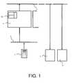
figure 1 représente le synoptique général de la partie du système de vol comportant les AHRS et un dispositif de contrôle selon l'invention ; - Les
figures 2 et 3 représentent une vue de la fenêtre de commande des deux AHRS dans deux configurations différentes selon l'invention.
- The
figure 1 represents the general block diagram of the part of the flight system comprising the AHRS and a control device according to the invention; - The
Figures 2 and 3 represent a view of the control window of the two AHRSs in two different configurations according to the invention.
La
- d'une part à un interface homme-
machine 2 de type « souris » informatique ou encore « CCD », pour « Cursor Control Device » qui, à l'aide d'un pointeur informatique, permet d'afficher, de modifier ou de paramétrer les informations affichées ; - d'autre part aux deux centrales de bord « AHRS » 3.
- on the one hand to a man-
machine interface 2 of "computer mouse" type or "CCD", for "Cursor Control Device" which, with the aid of a computer pointer, makes it possible to display, modify or modify set the information displayed; - on the other hand to the two "AHRS"
power plants 3.
Comme indiqué sur les
Le premier ensemble de symboles présenté dans la première zone et le second ensemble de symboles présenté dans la seconde zone comportent chacun :
- Des représentations de moyens de sélection du premier ou du second mode de fonctionnement des
AHRS 3 . Ce sont deux voyants circulaires 14 marqués « DG » et « SLAVE » sur lesfigures 2 . L'activation des voyants se traduit par un changement de couleur. Bien entendu, d'autres formes de voyants sont possibles ;et 3 Une représentation 15 de la valeur du cap magnétique de l'aéronef. Cette représentation peut être la valeur du cap inscrite dans un rectangle. Cette valeur vaut 055 sur lafigure 2 et 060 sur lafigure 3 . Dans ce cas, il devient possible de changer soit la couleur de la valeur du cap, soit la couleur du rectangle qui l'entoure ;Une représentation 16 de la différence de cap existant entre l'indication de cap fournie par le premier ensemble de mesures magnétomètriques et l'indication de cap fournie par le second ensemble de mesures gyroscopiques. Cette différence est symbolisée sur lesfigures 2 par un curseur en forme de triangle noir coulissant sous une barre disposée sous la représentation de la valeur duet 3cap 15. D'autres représentations sont également possibles afin d'assurer la même fonction ;
- Representations of means for selecting the first or second mode of operation of
AHRS 3. These are twocircular lights 14 marked "DG" and "SLAVE" on theFigures 2 and 3 . LED activation results in a color change. Of course, other forms of seers are possible; - A representation of the value of the magnetic heading of the aircraft. This representation can be the value of the heading inscribed in a rectangle. This value is 055 on the
figure 2 and 060 on thefigure 3 . In this case, it becomes possible to change either the color of the value of the heading, or the color of the rectangle which surrounds it; - A
representation 16 of the heading difference between the heading indication provided by the first set of magnetometric measurements and the heading indication provided by the second set of gyro measurements. This difference is symbolized on theFigures 2 and 3 by a slider in the form of a black triangle sliding under a bar disposed under the representation of the value of the heading 15. Other representations are also possible to ensure the same function;
Le troisième ensemble de symboles présenté dans la troisième zone comporte une représentation de moyens de sélection simultanée sur les deux AHRS d'un des deux types de mode. Il est représenté par deux boutons grisés notés DG et SLV sur les
Dans le dispositif selon l'invention, le procédé qui consiste à corriger un cap magnétique est le suivant :In the device according to the invention, the method of correcting a magnetic heading is as follows:
En mode normal appelé SLAVE, le cap courant est affiché en vert, afin d'indiquer que la valeur de cap à afficher est la valeur courante. La fonction de correction de cap n'est donc pas disponible dans ce cas. Ce cas est représenté sur la
Lorsque le mode DG est sélectionné, par exemple sur l'AHRS1 grâce au CCD interactif, le cap courant est affiché, par exemple, en cyan car il devint modifiable par le pilote. Cet état sélectionné DG est représenté par un voyant grisé sur la
Après sélection via le CCD interactif comme représenté en
Après validation de la valeur choisie, par appui sur la touche "entrée" du CCD interactif, la couleur du fond revient en mode normal video et l'information de cap redevient le cyan, puisque sa valeur est toujours modifiable, le mode DG étant toujours sélectionné, même si le pilote n'est plus en mode édition.After validation of the chosen value, by pressing the "input" key of the interactive CCD, the background color returns to normal video mode and the heading information becomes cyan again, since its value is always modifiable, the DG mode being always selected, even if the driver is no longer in edit mode.
Dans le cas ou la valeur retournée par l'AHRS et différente de la valeur sélectionnée par le pilote, la selection de cap est affichée, par exemple, en ambre afin de prévenir le pilote qu'un disfonctionnement vient d'être détecté.In the case where the value returned by the AHRS and different from the value selected by the pilot, the heading selection is displayed, for example, in amber to warn the pilot that a malfunction has just been detected.
Une barre disposée sous l'indication de cap permet de visualiser l'erreur de cap, à savoir la différence entre le cap magnétique et le cap gyroscopique.A bar placed under the heading indication makes it possible to visualize the heading error, namely the difference between the magnetic heading and the gyroscopic heading.
D'un point de vue fonctionnel, ce panneau de contrôle virtuel offre les mêmes fonctions que peuvent offrir aujourd'hui des interfaces mécaniques. Il offre également les fonctions supplémentaires suivantes :From a functional point of view, this virtual control panel offers the same functions that mechanical interfaces can offer today. It also offers the following additional features:
Le pilote peut passer en mode DG ou SLAVE l'une ou l'autre des AHRS par un simple click de son média interactif, mais peut aussi basculer les deux AHRS en même temps en mode DG ou SLAVE, ce que ne permettent pas aujourd'hui les interfaces mécaniques. Ainsi, à proximité des pôles, là ou les deux AHRS voient leur cap magnétique perturbé, le pilote peut passer les AHRS en mode DG en une seule action. Mais, en cas de panne du compas magnétique sur l'une des deux AHRS, le pilote peut passer cette AHRS en mode DG, tout en conservant l'autre AHRS en mode SLAVE afin maintenir un bon niveau de précision sur l'AHRS en bon fonctionnement.The pilot can switch to DG or SLAVE mode one or the other AHRS by a simple click of its interactive media, but can also switch both AHRS at the same time in DG or SLAVE mode, which do not allow today the mechanical interfaces. Thus, near the poles, where both AHRS have their magnetic heading disrupted, the pilot can switch the AHRS DG mode in one action. But, in case of magnetic compass failure on one of the two AHRS, the pilot can pass this AHRS DG mode, while retaining the other AHRS in SLAVE mode to maintain a good level of accuracy on the AHRS in good operation.
L'interface de contrôle de l'AHRS permet de rentrer directement la valeur de cap désirée. En effet, le sélection du cap d'initialisation se fait au moyen d'un rotacteur ou d'un clavier numérique avec visualisation sur le panneau de contrôle de la valeur sélectionnée, ce qui permet de saisir plus rapidement et sans itération la valeur de cap souhaitée.The control interface of the AHRS allows to enter the desired heading value directly. In fact, the initialization cap is selected by means of a rotator or a keypad with visualization on the control panel of the selected value, which makes it possible to enter the heading value more quickly and without iteration. desired.
La définition de l'interface virtuelle intègre des contrôles sur les retours envoyés par l'AHRS, ce que ne permet pas une interface mécanique. En effet, dans le cas d'interfaces mécaniques, si l'AHRS ne reçoit pas correctement l'information de correction ou tout simplement, si l'AHRS met plus de temps à corriger l'information de cap, le pilote peut ne pas s'en apercevoir car aucun message de panne n'est remonté au pilote. Au travers de l'interface virtuelle selon l'invention, dans le cas ou la valeur de cap retournée par l'AHRS n'est pas la même que celle sélectionnée par le pilote, la couleur de la valeur sélectionnée par le pilote peut être d'une couleur différente de celle habituellement affichée afin de l'avertir.The definition of the virtual interface integrates controls on the returns sent by the AHRS, which does not allow a mechanical interface. Indeed, in the case of mechanical interfaces, if the AHRS does not correctly receive the correction information or simply, if the AHRS puts more time to correct the heading information, the pilot may not notice it because no fault message is reported to the pilot. Through the virtual interface according to the invention, in the case where the value of heading returned by the AHRS is not the same as that selected by the pilot, the color of the value selected by the pilot can be d a color different from that usually displayed to warn.
Claims (4)
- A control device for two AHRS type attitude units (3) for aircraft, each AHRS comprising at least one first set of magnetometric measurements and at least one second set of gyroscopic measurements, each AHRS having two operating modes, a first mode, referred to as the "slave" mode and providing the flight system with the information originating from the first set, a second mode, referred to as the "DG" mode and providing the flight system with the information originating from the second set,
said device comprising at least one man-machine interface (2), at least one display device (1), connection means (4) between the man-machine interface and the display device, on the one hand, and the display device and the AHRS units, on the other hand,
characterised in that the display device includes means for displaying an instrumentation and control window (1) for the two attitude units, said window including three zones (11, 12, 13), the first zone (11) dedicated to the first AHRS unit, the second zone (12) dedicated to the second AHRS unit, the third zone (13) dedicated to the simultaneous control of the two AHRS units. - The control device according to claim 1,characterised in that the first set of symbols shown in the first zone and the second set of symbols shown in the second zone include:• representations (14) of the means of selecting the first or the second operating mode of the first or the second AHRS;• a representation (15) of the value of the magnetic heading of the aircraft;• a representation (16) of the difference in the heading which exists between the heading indication provided by the first set and the heading indication provided by the second set;andcharacterised in that the third set of symbols shown in the third zone includes a representation (17) of means of simultaneously selecting one of the two types of mode from the two AHRS.
- The control device according to claim 2,characterised in that the representation of the magnetic heading value of the aircraft is different in "slave" mode to the display of the magnetic heading value of the aircraft in "DG" mode.
- The control device according to claim 3,characterised in that, in "DG" mode, the representation of the magnetic heading value when the AHRS provides a measurement equal to the displayed value differs from the display of the magnetic heading value when the AHRS provides a measurement which differs from the displayed value.
Applications Claiming Priority (1)
| Application Number | Priority Date | Filing Date | Title |
|---|---|---|---|
| FR0708216AFR2924212B1 (en) | 2007-11-23 | 2007-11-23 | VIRTUAL CONTROL PANEL OF AERONAUTICAL ATTITUDE PLANTS |
Publications (2)
| Publication Number | Publication Date |
|---|---|
| EP2063227A1 EP2063227A1 (en) | 2009-05-27 |
| EP2063227B1true EP2063227B1 (en) | 2010-05-19 |
Family
ID=39791539
Family Applications (1)
| Application Number | Title | Priority Date | Filing Date |
|---|---|---|---|
| EP08169663ACeasedEP2063227B1 (en) | 2007-11-23 | 2008-11-21 | Virtual control panel for aeronautical attitude control units |
Country Status (4)
| Country | Link |
|---|---|
| US (1) | US8078343B2 (en) |
| EP (1) | EP2063227B1 (en) |
| DE (1) | DE602008001303D1 (en) |
| FR (1) | FR2924212B1 (en) |
Cited By (4)
| Publication number | Priority date | Publication date | Assignee | Title |
|---|---|---|---|---|
| USD726758S1 (en) | 2013-03-15 | 2015-04-14 | Airbus Operations (S.A.S.) | Aircraft cockpit display screen with graphical user interface |
| US9280904B2 (en) | 2013-03-15 | 2016-03-08 | Airbus Operations (S.A.S.) | Methods, systems and computer readable media for arming aircraft runway approach guidance modes |
| USD766278S1 (en) | 2013-09-16 | 2016-09-13 | Airbus Operations (S.A.S.) | Display screen with a graphical user interface |
| USD768141S1 (en) | 2013-09-16 | 2016-10-04 | Airbus Operations (S.A.S.) | Display screen with a graphical user interface |
Families Citing this family (7)
| Publication number | Priority date | Publication date | Assignee | Title |
|---|---|---|---|---|
| FR2983176B1 (en)* | 2011-11-29 | 2013-12-27 | Airbus Operations Sas | INTERACTIVE DIALOGUE DEVICE BETWEEN AN OPERATOR OF AN AIRCRAFT AND A GUIDE SYSTEM FOR SAID AIRCRAFT. |
| FR2983177B1 (en)* | 2011-11-29 | 2014-06-06 | Airbus Operations Sas | INTERACTIVE DIALOGUE DEVICE BETWEEN AN OPERATOR OF AN AIRCRAFT AND A GUIDE SYSTEM FOR SAID AIRCRAFT. |
| FR3001066B1 (en) | 2013-01-11 | 2015-02-27 | Airbus Operations Sas | SYSTEM FOR GUIDING ACTION ASSISTANCE TO BE CARRIED OUT BY AN OPERATOR ON AN AIRCRAFT. |
| US9567099B2 (en) | 2013-04-11 | 2017-02-14 | Airbus Operations (S.A.S.) | Aircraft flight management devices, systems, computer readable media and related methods |
| US10837780B2 (en) | 2016-10-17 | 2020-11-17 | FLIR Belgium BVBA | Mobile structure heading and piloting systems and methods |
| US10697795B2 (en)* | 2018-02-12 | 2020-06-30 | Bell Textron Inc. | Automatic heading correction for directional gyroscopes |
| FR3134474B1 (en)* | 2022-04-12 | 2024-04-12 | Thales Sa | Device and method for centralized management of a flight management system for aircraft |
Family Cites Families (7)
| Publication number | Priority date | Publication date | Assignee | Title |
|---|---|---|---|---|
| IL46339A (en)* | 1974-01-02 | 1977-10-31 | Gen Electric | System for controlling heading indication of an aircraft |
| US4283705A (en)* | 1979-05-30 | 1981-08-11 | Robert James | System for providing an integrated display of instantaneous information relative to aircraft attitude, heading, altitude, and horizontal situation |
| AU6488400A (en)* | 1999-04-01 | 2000-11-10 | Ricardo A. Price | Electronic flight instrument displays |
| US6853315B2 (en)* | 2002-01-23 | 2005-02-08 | Triad Sensors, Inc. | Piezoelectric rate sensor system and method |
| US7248964B2 (en)* | 2003-12-05 | 2007-07-24 | Honeywell International Inc. | System and method for using multiple aiding sensors in a deeply integrated navigation system |
| US7107833B2 (en)* | 2003-12-23 | 2006-09-19 | Honeywell International Inc. | Inertial reference unit with internal backup attitude heading reference system |
| CA2602495C (en)* | 2004-04-29 | 2014-07-15 | Jadi, Inc. | Artificial horizon device and method |
- 2007
- 2007-11-23FRFR0708216Apatent/FR2924212B1/ennot_activeExpired - Fee Related
- 2008
- 2008-11-21USUS12/275,483patent/US8078343B2/ennot_activeExpired - Fee Related
- 2008-11-21DEDE602008001303Tpatent/DE602008001303D1/enactiveActive
- 2008-11-21EPEP08169663Apatent/EP2063227B1/ennot_activeCeased
Cited By (4)
| Publication number | Priority date | Publication date | Assignee | Title |
|---|---|---|---|---|
| USD726758S1 (en) | 2013-03-15 | 2015-04-14 | Airbus Operations (S.A.S.) | Aircraft cockpit display screen with graphical user interface |
| US9280904B2 (en) | 2013-03-15 | 2016-03-08 | Airbus Operations (S.A.S.) | Methods, systems and computer readable media for arming aircraft runway approach guidance modes |
| USD766278S1 (en) | 2013-09-16 | 2016-09-13 | Airbus Operations (S.A.S.) | Display screen with a graphical user interface |
| USD768141S1 (en) | 2013-09-16 | 2016-10-04 | Airbus Operations (S.A.S.) | Display screen with a graphical user interface |
Also Published As
| Publication number | Publication date |
|---|---|
| US20090138143A1 (en) | 2009-05-28 |
| FR2924212A1 (en) | 2009-05-29 |
| US8078343B2 (en) | 2011-12-13 |
| DE602008001303D1 (en) | 2010-07-01 |
| EP2063227A1 (en) | 2009-05-27 |
| FR2924212B1 (en) | 2010-02-26 |
Similar Documents
| Publication | Publication Date | Title |
|---|---|---|
| EP2063227B1 (en) | Virtual control panel for aeronautical attitude control units | |
| FR3052889B1 (en) | VIBRATION-INDUCED ERROR CORRECTION FOR TOUCH SCREEN DISPLAY IN AN AIRCRAFT | |
| FR2689290A1 (en) | Method and device for multimode and multifunction communication between an operator and one or more processors. | |
| FR2921190A1 (en) | DEVICE FOR PRESENTING AND SELECTING DATA ON A DISPLAY SCREEN | |
| EP1938047B1 (en) | Display system for an aircraft | |
| EP2300322B1 (en) | Aircraft control cabin with avionics display device | |
| EP2645066B1 (en) | Display system for an aircraft and associated method | |
| FR2903787A1 (en) | DEVICE FOR GENERATING THE EMERGENCY FUNCTION IN A HIGH HEAD VIEWFINDER | |
| FR2969124A1 (en) | METHOD OF TIME DISPLAYING THE MISSION OF AN AIRCRAFT | |
| US20150029018A1 (en) | Articulating instrument cluster | |
| FR2935179A1 (en) | On-board system controlling assisting method for aircraft, involves selecting elements to be displayed in set of predetermined elements based on state of aircraft, and displaying elements under text or graphical form on display device | |
| FR2904461A1 (en) | METHOD AND DEVICE FOR DISPLAYING A FLIGHT PLAN OF AN AIRCRAFT | |
| US9128594B1 (en) | Touch interfaces and controls for aviation displays | |
| EP2555105A2 (en) | Touch screen having adaptive input requirements | |
| US20160293142A1 (en) | Graphical user interface (gui) shading based on context | |
| US20170072801A1 (en) | Clustered instrument panel in a transportation apparatus | |
| US20170072796A1 (en) | Clustered instrument panel in a transportation apparatus | |
| FR2993975A1 (en) | METHOD FOR DISPLAYING THE GEOGRAPHICAL SITUATION OF AN AIRCRAFT | |
| FR3134474A1 (en) | Device and method for centralized management of a flight management system for aircraft | |
| US8767013B2 (en) | System and method for rendering a sky veil on a vehicle display | |
| FR2998407A1 (en) | AIRCRAFT STEERING SYSTEM DISPLAY SYSTEMS | |
| EP2064118A1 (en) | Backup instrument for an aircraft instrument panel detecting overload, particularly during the landing phase | |
| EP3112814A1 (en) | Viewing system comprising means for selecting, sharing and displaying graphical objects in different viewing modes and method therefore | |
| CN107977179B (en) | Method and device for cross-screen display and/or operation in a vehicle | |
| CN110390912A (en) | Method and apparatus for display module control system |
Legal Events
| Date | Code | Title | Description |
|---|---|---|---|
| PUAI | Public reference made under article 153(3) epc to a published international application that has entered the european phase | Free format text:ORIGINAL CODE: 0009012 | |
| AK | Designated contracting states | Kind code of ref document:A1 Designated state(s):AT BE BG CH CY CZ DE DK EE ES FI FR GB GR HR HU IE IS IT LI LT LU LV MC MT NL NO PL PT RO SE SI SK TR | |
| AX | Request for extension of the european patent | Extension state:AL BA MK RS | |
| 17P | Request for examination filed | Effective date:20091022 | |
| GRAP | Despatch of communication of intention to grant a patent | Free format text:ORIGINAL CODE: EPIDOSNIGR1 | |
| AKX | Designation fees paid | Designated state(s):DE FR GB IT | |
| GRAS | Grant fee paid | Free format text:ORIGINAL CODE: EPIDOSNIGR3 | |
| GRAA | (expected) grant | Free format text:ORIGINAL CODE: 0009210 | |
| AK | Designated contracting states | Kind code of ref document:B1 Designated state(s):DE FR GB IT | |
| REG | Reference to a national code | Ref country code:GB Ref legal event code:FG4D Free format text:NOT ENGLISH | |
| REF | Corresponds to: | Ref document number:602008001303 Country of ref document:DE Date of ref document:20100701 Kind code of ref document:P | |
| PLBE | No opposition filed within time limit | Free format text:ORIGINAL CODE: 0009261 | |
| STAA | Information on the status of an ep patent application or granted ep patent | Free format text:STATUS: NO OPPOSITION FILED WITHIN TIME LIMIT | |
| 26N | No opposition filed | Effective date:20110222 | |
| REG | Reference to a national code | Ref country code:DE Ref legal event code:R097 Ref document number:602008001303 Country of ref document:DE Effective date:20110221 | |
| REG | Reference to a national code | Ref country code:FR Ref legal event code:PLFP Year of fee payment:8 | |
| REG | Reference to a national code | Ref country code:FR Ref legal event code:PLFP Year of fee payment:9 | |
| REG | Reference to a national code | Ref country code:FR Ref legal event code:PLFP Year of fee payment:10 | |
| REG | Reference to a national code | Ref country code:FR Ref legal event code:PLFP Year of fee payment:11 | |
| PGFP | Annual fee paid to national office [announced via postgrant information from national office to epo] | Ref country code:DE Payment date:20201110 Year of fee payment:13 Ref country code:IT Payment date:20201027 Year of fee payment:13 Ref country code:FR Payment date:20201026 Year of fee payment:13 Ref country code:GB Payment date:20201111 Year of fee payment:13 | |
| REG | Reference to a national code | Ref country code:DE Ref legal event code:R119 Ref document number:602008001303 Country of ref document:DE | |
| GBPC | Gb: european patent ceased through non-payment of renewal fee | Effective date:20211121 | |
| PG25 | Lapsed in a contracting state [announced via postgrant information from national office to epo] | Ref country code:GB Free format text:LAPSE BECAUSE OF NON-PAYMENT OF DUE FEES Effective date:20211121 Ref country code:DE Free format text:LAPSE BECAUSE OF NON-PAYMENT OF DUE FEES Effective date:20220601 | |
| PG25 | Lapsed in a contracting state [announced via postgrant information from national office to epo] | Ref country code:FR Free format text:LAPSE BECAUSE OF NON-PAYMENT OF DUE FEES Effective date:20211130 | |
| PG25 | Lapsed in a contracting state [announced via postgrant information from national office to epo] | Ref country code:IT Free format text:LAPSE BECAUSE OF NON-PAYMENT OF DUE FEES Effective date:20211121 | |
| P01 | Opt-out of the competence of the unified patent court (upc) registered | Effective date:20230427 |