EP2061391B1 - Intercostal spacer device for correcting a spinal deformity - Google Patents
Intercostal spacer device for correcting a spinal deformityDownload PDFInfo
- Publication number
- EP2061391B1 EP2061391B1EP07841956AEP07841956AEP2061391B1EP 2061391 B1EP2061391 B1EP 2061391B1EP 07841956 AEP07841956 AEP 07841956AEP 07841956 AEP07841956 AEP 07841956AEP 2061391 B1EP2061391 B1EP 2061391B1
- Authority
- EP
- European Patent Office
- Prior art keywords
- intercostal
- arms
- spacer device
- pair
- intercostal spacer
- Prior art date
- Legal status (The legal status is an assumption and is not a legal conclusion. Google has not performed a legal analysis and makes no representation as to the accuracy of the status listed.)
- Not-in-force
Links
- 125000006850spacer groupChemical group0.000titleclaimsabstractdescription221
- 230000003601intercostal effectEffects0.000titleclaimsabstractdescription212
- 206010058907Spinal deformityDiseases0.000titleclaimsabstractdescription25
- 239000000463materialSubstances0.000claimsdescription56
- 238000000034methodMethods0.000description24
- 238000002513implantationMethods0.000description16
- 210000000038chestAnatomy0.000description11
- 229910001285shape-memory alloyInorganic materials0.000description11
- -1polyethylenePolymers0.000description8
- 229920000642polymerPolymers0.000description7
- 239000004744fabricSubstances0.000description6
- 229910052751metalInorganic materials0.000description6
- 239000002184metalSubstances0.000description6
- 229920001296polysiloxanePolymers0.000description6
- 239000000835fiberSubstances0.000description5
- 239000007943implantSubstances0.000description5
- 210000000988bone and boneAnatomy0.000description4
- 239000004815dispersion polymerSubstances0.000description4
- 229920001971elastomerPolymers0.000description4
- 229920000139polyethylene terephthalatePolymers0.000description4
- 239000005020polyethylene terephthalateSubstances0.000description4
- 239000005060rubberSubstances0.000description4
- 229920000049Carbon (fiber)Polymers0.000description3
- 239000004698PolyethyleneSubstances0.000description3
- RTAQQCXQSZGOHL-UHFFFAOYSA-NTitaniumChemical compound[Ti]RTAQQCXQSZGOHL-UHFFFAOYSA-N0.000description3
- 239000004917carbon fiberSubstances0.000description3
- 239000002131composite materialSubstances0.000description3
- 230000001419dependent effectEffects0.000description3
- 238000011065in-situ storageMethods0.000description3
- VNWKTOKETHGBQD-UHFFFAOYSA-NmethaneChemical compoundCVNWKTOKETHGBQD-UHFFFAOYSA-N0.000description3
- 230000035699permeabilityEffects0.000description3
- 229920000573polyethylenePolymers0.000description3
- 229920002635polyurethanePolymers0.000description3
- 239000004814polyurethaneSubstances0.000description3
- 229910052719titaniumInorganic materials0.000description3
- 239000010936titaniumSubstances0.000description3
- 239000004743PolypropyleneSubstances0.000description2
- 229910000831SteelInorganic materials0.000description2
- 238000013459approachMethods0.000description2
- 239000011324beadSubstances0.000description2
- 239000000560biocompatible materialSubstances0.000description2
- 230000036760body temperatureEffects0.000description2
- 239000012611container materialSubstances0.000description2
- 238000012937correctionMethods0.000description2
- 230000008878couplingEffects0.000description2
- 238000010168coupling processMethods0.000description2
- 238000005859coupling reactionMethods0.000description2
- 230000001747exhibiting effectEffects0.000description2
- 230000035876healingEffects0.000description2
- 239000007788liquidSubstances0.000description2
- 229910001092metal group alloyInorganic materials0.000description2
- 150000002739metalsChemical class0.000description2
- 229920001155polypropylenePolymers0.000description2
- 206010039722scoliosisDiseases0.000description2
- 239000007787solidSubstances0.000description2
- 239000010959steelSubstances0.000description2
- 238000001356surgical procedureMethods0.000description2
- XLYOFNOQVPJJNP-UHFFFAOYSA-NwaterSubstancesOXLYOFNOQVPJJNP-UHFFFAOYSA-N0.000description2
- 102000009027AlbuminsHuman genes0.000description1
- 108010088751AlbuminsProteins0.000description1
- 229910000684Cobalt-chromeInorganic materials0.000description1
- 102000008186CollagenHuman genes0.000description1
- 108010035532CollagenProteins0.000description1
- 239000004593EpoxySubstances0.000description1
- 102000008946FibrinogenHuman genes0.000description1
- 108010049003FibrinogenProteins0.000description1
- AEMRFAOFKBGASW-UHFFFAOYSA-NGlycolic acidPolymersOCC(O)=OAEMRFAOFKBGASW-UHFFFAOYSA-N0.000description1
- OUYCCCASQSFEME-QMMMGPOBSA-NL-tyrosineChemical compoundOC(=O)[C@@H](N)CC1=CC=C(O)C=C1OUYCCCASQSFEME-QMMMGPOBSA-N0.000description1
- 239000004696Poly ether ether ketoneSubstances0.000description1
- 239000004952PolyamideSubstances0.000description1
- 229920002732PolyanhydridePolymers0.000description1
- 229920000954PolyglycolidePolymers0.000description1
- 229920001710PolyorthoesterPolymers0.000description1
- 239000004372Polyvinyl alcoholSubstances0.000description1
- 208000000875Spinal CurvaturesDiseases0.000description1
- 229910001069Ti alloyInorganic materials0.000description1
- 230000002159abnormal effectEffects0.000description1
- 230000004913activationEffects0.000description1
- 238000007792additionMethods0.000description1
- 239000000853adhesiveSubstances0.000description1
- 230000001070adhesive effectEffects0.000description1
- 229910045601alloyInorganic materials0.000description1
- 239000000956alloySubstances0.000description1
- 230000003190augmentative effectEffects0.000description1
- 229910052788bariumInorganic materials0.000description1
- DSAJWYNOEDNPEQ-UHFFFAOYSA-Nbarium atomChemical compound[Ba]DSAJWYNOEDNPEQ-UHFFFAOYSA-N0.000description1
- 239000005313bioactive glassSubstances0.000description1
- 230000008468bone growthEffects0.000description1
- 229910000389calcium phosphateInorganic materials0.000description1
- 239000001506calcium phosphateSubstances0.000description1
- 235000011010calcium phosphatesNutrition0.000description1
- 230000008859changeEffects0.000description1
- 239000011248coating agentSubstances0.000description1
- 238000000576coating methodMethods0.000description1
- 239000010952cobalt-chromeSubstances0.000description1
- 229920001436collagenPolymers0.000description1
- 230000008602contractionEffects0.000description1
- 229940012952fibrinogenDrugs0.000description1
- 239000012530fluidSubstances0.000description1
- 230000004927fusionEffects0.000description1
- 229910052588hydroxylapatiteInorganic materials0.000description1
- 238000003384imaging methodMethods0.000description1
- 238000001727in vivoMethods0.000description1
- 238000003780insertionMethods0.000description1
- 230000037431insertionEffects0.000description1
- 238000012986modificationMethods0.000description1
- 230000004048modificationEffects0.000description1
- 238000000465mouldingMethods0.000description1
- 229910001000nickel titaniumInorganic materials0.000description1
- HLXZNVUGXRDIFK-UHFFFAOYSA-Nnickel titaniumChemical compound[Ti].[Ti].[Ti].[Ti].[Ti].[Ti].[Ti].[Ti].[Ti].[Ti].[Ti].[Ni].[Ni].[Ni].[Ni].[Ni].[Ni].[Ni].[Ni].[Ni].[Ni].[Ni].[Ni].[Ni].[Ni]HLXZNVUGXRDIFK-UHFFFAOYSA-N0.000description1
- 229910052755nonmetalInorganic materials0.000description1
- 150000002843nonmetalsChemical class0.000description1
- XYJRXVWERLGGKC-UHFFFAOYSA-Dpentacalcium;hydroxide;triphosphateChemical compound[OH-].[Ca+2].[Ca+2].[Ca+2].[Ca+2].[Ca+2].[O-]P([O-])([O-])=O.[O-]P([O-])([O-])=O.[O-]P([O-])([O-])=OXYJRXVWERLGGKC-UHFFFAOYSA-D0.000description1
- 229920003023plasticPolymers0.000description1
- 239000004033plasticSubstances0.000description1
- 229920000747poly(lactic acid)Polymers0.000description1
- 239000002745poly(ortho ester)Substances0.000description1
- 229920002627poly(phosphazenes)Polymers0.000description1
- 229920002239polyacrylonitrilePolymers0.000description1
- 229920002647polyamidePolymers0.000description1
- 229920000515polycarbonatePolymers0.000description1
- 239000004417polycarbonateSubstances0.000description1
- 229920001692polycarbonate urethanePolymers0.000description1
- 229920000728polyesterPolymers0.000description1
- 229920002530polyetherether ketonePolymers0.000description1
- 229920000098polyolefinPolymers0.000description1
- 229920001343polytetrafluoroethylenePolymers0.000description1
- 229920002451polyvinyl alcoholPolymers0.000description1
- 230000008569processEffects0.000description1
- 239000003566sealing materialSubstances0.000description1
- 239000002356single layerSubstances0.000description1
- 230000000087stabilizing effectEffects0.000description1
- 229910001220stainless steelInorganic materials0.000description1
- 239000010935stainless steelSubstances0.000description1
- 238000006467substitution reactionMethods0.000description1
- 229910052715tantalumInorganic materials0.000description1
- GUVRBAGPIYLISA-UHFFFAOYSA-Ntantalum atomChemical compound[Ta]GUVRBAGPIYLISA-UHFFFAOYSA-N0.000description1
- MHSKRLJMQQNJNC-UHFFFAOYSA-NterephthalamideChemical compoundNC(=O)C1=CC=C(C(N)=O)C=C1MHSKRLJMQQNJNC-UHFFFAOYSA-N0.000description1
- 210000001519tissueAnatomy0.000description1
- 230000008467tissue growthEffects0.000description1
- QORWJWZARLRLPR-UHFFFAOYSA-Htricalcium bis(phosphate)Chemical compound[Ca+2].[Ca+2].[Ca+2].[O-]P([O-])([O-])=O.[O-]P([O-])([O-])=OQORWJWZARLRLPR-UHFFFAOYSA-H0.000description1
- OUYCCCASQSFEME-UHFFFAOYSA-NtyrosineNatural productsOC(=O)C(N)CC1=CC=C(O)C=C1OUYCCCASQSFEME-UHFFFAOYSA-N0.000description1
Images


Classifications
- A—HUMAN NECESSITIES
- A61—MEDICAL OR VETERINARY SCIENCE; HYGIENE
- A61B—DIAGNOSIS; SURGERY; IDENTIFICATION
- A61B17/00—Surgical instruments, devices or methods
- A61B17/56—Surgical instruments or methods for treatment of bones or joints; Devices specially adapted therefor
- A61B17/58—Surgical instruments or methods for treatment of bones or joints; Devices specially adapted therefor for osteosynthesis, e.g. bone plates, screws or setting implements
- A61B17/68—Internal fixation devices, including fasteners and spinal fixators, even if a part thereof projects from the skin
- A61B17/80—Cortical plates, i.e. bone plates; Instruments for holding or positioning cortical plates, or for compressing bones attached to cortical plates
- A61B17/8061—Cortical plates, i.e. bone plates; Instruments for holding or positioning cortical plates, or for compressing bones attached to cortical plates specially adapted for particular bones
- A61B17/8076—Cortical plates, i.e. bone plates; Instruments for holding or positioning cortical plates, or for compressing bones attached to cortical plates specially adapted for particular bones for the ribs or the sternum
- A—HUMAN NECESSITIES
- A61—MEDICAL OR VETERINARY SCIENCE; HYGIENE
- A61B—DIAGNOSIS; SURGERY; IDENTIFICATION
- A61B17/00—Surgical instruments, devices or methods
- A61B17/56—Surgical instruments or methods for treatment of bones or joints; Devices specially adapted therefor
- A61B17/58—Surgical instruments or methods for treatment of bones or joints; Devices specially adapted therefor for osteosynthesis, e.g. bone plates, screws or setting implements
- A61B17/68—Internal fixation devices, including fasteners and spinal fixators, even if a part thereof projects from the skin
- A61B17/70—Spinal positioners or stabilisers, e.g. stabilisers comprising fluid filler in an implant
- A61B17/7062—Devices acting on, attached to, or simulating the effect of, vertebral processes, vertebral facets or ribs ; Tools for such devices
- A61B17/707—Devices acting on, or attached to, a transverse process or rib; Tools therefor
- A—HUMAN NECESSITIES
- A61—MEDICAL OR VETERINARY SCIENCE; HYGIENE
- A61B—DIAGNOSIS; SURGERY; IDENTIFICATION
- A61B17/00—Surgical instruments, devices or methods
- A61B17/56—Surgical instruments or methods for treatment of bones or joints; Devices specially adapted therefor
- A61B17/58—Surgical instruments or methods for treatment of bones or joints; Devices specially adapted therefor for osteosynthesis, e.g. bone plates, screws or setting implements
- A61B17/68—Internal fixation devices, including fasteners and spinal fixators, even if a part thereof projects from the skin
- A61B17/70—Spinal positioners or stabilisers, e.g. stabilisers comprising fluid filler in an implant
- A61B17/7062—Devices acting on, attached to, or simulating the effect of, vertebral processes, vertebral facets or ribs ; Tools for such devices
- A—HUMAN NECESSITIES
- A61—MEDICAL OR VETERINARY SCIENCE; HYGIENE
- A61B—DIAGNOSIS; SURGERY; IDENTIFICATION
- A61B17/00—Surgical instruments, devices or methods
- A61B2017/00831—Material properties
- A61B2017/00867—Material properties shape memory effect
Definitions
- the present inventionrelates generally to orthopaedic implants used for the correction of spinal deformities, and more specifically, but not exclusively, concerns apparatuses placed within the intercostal space of two ribs to allow for deformity correction or healing of the spinal column.
- Typical spinal implant systemsare implanted through a posterior approach to the spinal column and utilize a rod as the support and stabilizing element connected to a series of two or more bone fasteners that have been inserted into two or more vertebrae. The connections between these components are then secured, thereby fixing a supporting construct to multiple levels in the spinal column.
- FR2623085 , FR2775183 , FR2799640 and EP1138268disclose known intervertebral implants.
- US5261908describes a known prosthetic rib which is expandable.
- the present inventionsatisfies the need for improvements to the surgical treatment by providing a more mechanically efficient intercostal spacer device for implantation into multiple intercostal spaces of a patient's rib cage.
- the intercostal spacer deviceis a one piece construct fabricated from a biocompatible material.
- the intercostal spacer devicemay be a multiple piece construct that includes a flexible container that is fillable in situ to a desired amount, with a structure for at least part of the container providing shape control of the intercostal spacer device.
- An optional conduit coupled to the containerallows for filling of the container, for example, by injecting a material into the container.
- an intercostal spacer deviceincludes a spacer member that has a superior end and an inferior end. Extending from both the superior end and inferior end are at least one pair of arms with a channel defined between each pair of arms.
- the spacer memberis sized and configured to enable placement of the spacer member within an intercostal space, with each channel being sized to receive a rib allowing the intercostal spacer device to resist dislodgement from the ribs and produce a force for correcting a spinal deformity.
- an intercostal spacer devicethat includes a flexible container for receiving an injectable material that is compressible following implantation between two adjacent ribs, wherein the flexible container is substantially impermeable to the injectable material.
- the intercostal spacer devicefurther includes a conduit coupled to the flexible container for accepting the injectable material, and a structure for at least part of the flexible container when containing the material, wherein the structure has a shape to fit between two adjacent ribs.
- a method of controlling at least part of the shape of the intercostal spacer devicehas a flexible container for containing an injectable material that is compressible following implantation, wherein the container is substantially impermeable to the injectable material.
- the intercostal spacer devicefurther includes a structure for at least part of the flexible container. The method provides for creating the structure with at least one material for controlling at least part of the shape of the intercostal spacer device following implantation into the intercostal space.
- an intercostal spacer systemincludes a plurality of intercostal spacer devices, with each of the intercostal spacer devices having a spacer member that has a superior end and an inferior end. Extending from both the superior end and inferior end are at least one pair of arms with a channel being defined between each pair of arms.
- the spacer memberis sized and configured to enable placement of the member within an intercostal space, with each channel being sized to receive a rib, allowing the intercostal spacer device to resist dislodgement from the ribs when implanted.
- the plurality of intercostal spacer devicescooperate to dynamically produce a force for correcting a spinal deformity within a patient.
- the methodincludes the step of providing at least one intercostal spacer device, the intercostal spacer device includes a spacer member having first and second ends with at least one pair of arms extending from each of the first and second ends.
- the spacer member, the first pair of arms extending from the first end and the second pair of arms extending from the second end of the at least one intercostal spacerare sized for placement between a first rib and an adjacent second rib of a patient.
- the methodfurther includes the positioning of the at least one intercostal spacer device into the intercostal space between the two adjacent ribs of the patient with the first rib disposed between the first pair of arms and the adjacent second rib disposed between the second pair of arms and thus securing the intercostal spacer device within the intercostal space and producing a force to correct the spinal deformity of the patient.
- the methodincludes providing an intercostal spacer device, the intercostal spacer device includes a flexible container for containing an injectable material that is compressible following implantation, wherein the flexible container is substantially impermeable to the injectable material.
- the intercostal spacer devicefurther includes a conduit coupled to the flexible container for accepting the injectable material, and a structure for at least part of the flexible container when containing the material, wherein the structure has a shape of the intercostal spacer device that is sized and configured to fit between adjacent ribs in a patient.
- the methodfurther includes implanting the intercostal spacer device between two adjacent ribs. The injectable material is then injected into the flexible container through the conduit such that the shape of the structure is achieved, thus producing a force to correct the spinal deformity of the patient.
- an intercostal spacer device 10includes a spacer member 11 comprising a superior end 12 and an inferior end 13 with a central axis (not shown) extending between superior end 12 and inferior end 13.
- a spacer member 11comprising a superior end 12 and an inferior end 13 with a central axis (not shown) extending between superior end 12 and inferior end 13.
- Extending in an upward direction from superior end 12is preferably one pair of arms 14 that may include an anterior arm 15 and a posterior arm 16.
- extending in a downward direction from inferior end 13is preferably one pair of arms 17 that may include an anterior arm 18 and a posterior arm 19.
- Each pair of arms 14, 17are integral to spacer member 11 and are sized to resist dislodgement of intercostal spacer device 10 following placement within the intercostal space.
- each pair of arms 14, 17are centered about the central axis of spacer member 11 resulting in a roughly H-shaped overall structure.
- An upper channel 20is typically defined by a seat 22, anterior arm 15 and posterior arm 16.
- a lower channel 21is defined by a seat 23, anterior arm 18 and posterior arm 19.
- Anterior arm 15 and posterior arm 16are disposed relatively parallel to each other and project in an upward manner from seat 22.
- Anterior arm 18 and posterior arm 19project in a downward manner from seat 23 and are substantially parallel to each other.
- Each pair of arms 14, 17, together with seats 22, 23form U-shaped channels 20, 21 respectively, which are each appropriately sized to receive a rib 30.
- intercostal spacer device 10is maneuvered in a manner allowing two adjacent ribs 30 to be positioned within channels 20, 21, causing the anterior aspect of the two adjacent ribs 30 to contact anterior arms 15, 18 and the posterior aspect of the two adjacent ribs 30 to contact posterior arms 16, 19.
- intercostal spacer device 10includes a spacer member 11 comprising a superior end 12 and an inferior end 13. Extending in an upward direction from superior end 12 is preferably one pair of arms 14 that may include an anterior arm 15 and a posterior arm 16. Further, extending in a downward direction from inferior end 13 is preferably one pair of arms 17 that may include an anterior arm 18 and a posterior arm 19.
- An upper channel 20is typically defined by a seat 22, anterior arm 15 and posterior arm 16. Additionally, a lower channel 21 is defined by a seat 23, anterior arm 18 and posterior arm 19.
- Each pair of arms 14, 17 together with seats 22, 23form U-shaped channels 20, 21 respectively, which are each appropriately sized to receive a rib 30.
- At least one through hole 24is directed in the anterior to posterior direction and located within spacer member 11 in the intercostal spacer device 10.
- connector 40(see FIG. 1B ) is inserted into hole 24 following the placement of intercostal spacer device 10 between adjacent ribs 30.
- a first connector 40may be inserted through passage or hole 24 that extends from an anterior surface 31 of spacer member 11 to a posterior surface 32 of spacer member and then wraps over the superior surface of rib 30 which is positioned within upper channel 20.
- a second connector 40may be inserted through a second passage or hole 24 that extends from anterior surface 31 of spacer member 11 to posterior surface 32 of spacer member 11 and then wraps over the inferior surface of a second adjacent rib 30 which is positioned within lower channel 21.
- the ends of connectors 40may be secured using crimps, knots, ties or other suitable fasteners. It is understood to those skilled in the art that other securement techniques and configurations are contemplated and will depend on the type of connector 40 used within intercostal spacer device 10.
- an alternative method of securing intercostal spacer device 10 within the intercostal spacemay include extending at least one connector 40 around the circumference of the exterior surface of intercostal spacer device 10 and the two adjacent ribs 30.
- the ends of connector 40may be then be secured using crimps, knots, ties or other suitable fasteners, although it is understood to those skilled in the art that other securement techniques and configurations are contemplated and will depend on the type of connector 40 used in securing intercostal spacer device 10 within the intercostal space.
- FIG. 1Ddepicts the use of at least one connector 40 typically utilizing a figure-8 configuration.
- a single or multiple connector 40may be inserted through an angled passage or hole 25 that extends from anterior surface 31 of spacer member 11 to posterior surface 32 of spacer member 11 and then looped over the superior surface of rib 30 which is positioned within upper channel 20.
- Connector 40is further passed through a second angled passage or hole 25 that extends from anterior surface 31 of spacer member 11 to posterior surface 32 of spacer member allowing connector 40 to also loop over the inferior surface of a second adjacent rib 30 which is positioned within lower channel 21.
- connector 40may be secured using crimps, knots, ties or other suitable fastener. It is understood to those skilled in the art that other securement techniques and configurations are contemplated and will depend on the type of connector 40 used within intercostal spacer device 10.
- Connector 40may be in the form of a wire, cable, tether, belt, band, cord or other suitable structure for securement within the intercostal space and may be fabricated from a material selected from the group consisting of carbon fiber composite polymers, bio-compatible metals, resorbable polymers, bio-inert polymeric materials, and any combinations of these materials.
- intercostal spacer device 10includes a spacer member 11 comprising a superior end 12 and an inferior end 13. Extending in an upward direction from superior end 12 is preferably one pair of arms 14, including anterior arm 15 and posterior arm 16. Further, extending in a downward direction from inferior end 13 is preferably one pair of arms 17 that may include anterior arm 18 and posterior arm 19. As provided above, upper channel 20 is typically defined by seat 22, anterior arm 15 and posterior arm 16. Additionally, lower channel 21 is defined by seat 23, anterior arm 18 and posterior arm 19. Each pair of arms 14, 17 together with seats 22, 23 form U-shaped channels 20, 21 respectively, which are each appropriately sized to receive a rib 30.
- At least one through hole 26is directed in an anterior to posterior direction and passes through anterior arms 15, 18 and posterior arms 16, 19 located within superior pair of arms 14 and inferior pair of arms 17, respectively.
- at least one hole 26extends through superior pair of arms 14 and is substantially parallel to a second hole 26 extending through inferior pair of arms 17.
- intercostal spacer device 10is placed within an intercostal space and typically is maneuvered in a manner to allow two adjacent ribs 30 to be positioned within upper and lower channels 20, 21, causing the anterior aspect of two adjacent ribs 30 to contact anterior arms 15, 18 and the posterior aspect of two adjacent ribs 30 to contact posterior arms 16, 19.
- a connector 41see FIG.
- one connector 41may be inserted through hole 26 that is located in the most upper portion of superior pair of arms 14 and span upper channel 20 and across the superior margin of rib 30.
- a second connector 41is inserted through a second hole 26 located in the most downward portion of inferior set of arms 17 and span lower channel 21 and across the inferior margin of rib 30.
- the ends of the two connectors 41may be secured using crimps, caps, nuts, rivets, or other suitable fastener device.
- Connector 41may be in the form of a bolt, screw, lock pin, rivet, staple, press-fit pin or other suitable structure for securement within the intercostal space and may be fabricated from a material selected from the group consisting of carbon fiber composite polymers, bio-compatible metals, resorbable polymers, bio-inert polymeric materials, and any combinations of these materials.
- FIG. 2depicts an intercostal spacer system that includes a plurality of intercostal spacer devices 10 placed within the rib cage to correct a spinal deformity of a patient.
- Multiple intercostal spacer devices 10are inserted into the intercostal spaces of several adjacent ribs 30 at corresponding deformed spinal levels.
- Adjacent intercostal spacer devices 10are preferably implanted in an offset manner relative to each other, resulting in an overall generally staggered arrangement.
- each of the plurality of intercostal spacer devices 10may be secured within the intercostal space with at least one connector 40, 41 (not shown).
- at least one connector 40may link or couple each of the plurality of intercostal spacer devices 10 to each other (not shown).
- the number of intercostal spacer devices 10 implantedmay be dependent upon the severity of the spinal deformity and the affected levels of the spinal column.
- three intercostal spacer devices 10are placed on the concave side of a medial-lateral deformity that spans four levels of the spinal column.
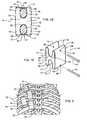
- FIG. 3depicts an embodiment of an intercostal spacer device 100 in accordance with an aspect of the present invention.
- Intercostal spacer device 100includes a spacer member 110 comprising of a superior end 112 and an inferior end 113 with a central axis (not shown) extending between superior end 112 and inferior end 113.
- Extending in an upward direction from superior end 112is preferably two pair of arms 114, with each pair of arms including an anterior arm 115 and a posterior arm 116.
- extending from inferior end 113 in a downward directionis preferably one pair of arms 117 that may include an anterior arm 118 and a posterior arm 119.
- Each pair of arms 114, 117are integral to spacer member 110 usually with one of the two superior pair of arms 114 being offset laterally relative to the central axis and the second of the two superior pair of arms 114 being offset medially relative to the central axis.
- the inferior pair of arms 117are preferably centered about the central axis resulting in a roughly Y-shaped overall structure defining intercostal spacer device 100.
- an upper channel 120is typically defined by a seat 122, anterior arm 115 and posterior arm 116.
- a lower channel 121is defined by a seat 123, anterior arm 118 and posterior arm 119.
- anterior arm 115 and posterior arm 116are disposed relatively parallel to each other and project in a generally upward manner from seat 122.
- anterior arm 118 and posterior arm 119project in a generally downward manner from seat 123 and are substantially parallel to each other.
- Each pair of arms 114, 117, together with seats 122, 123form U-shaped channels 120, 121 respectively, which are each appropriately sized to receive a rib 30 and allow intercostal spacer device 100 to resist dislodgement following implantation within the rib cage.
- connector 40, 41may be utilized with intercostal spacer device 100 to secure intercostal spacer device 100 within an intercostal space.
- connector 40may pass through anterior to posterior directed, single or multiple, straight or angled holes or passages (not shown) within spacer member 110, thereby allowing connector 40 to wrap or loop around or over both superior pair of arms 114 and inferior pair of arms 117 allowing for securement of intercostal spacer device 100 within the intercostal space in the same or similar manner as described above for intercostal spacer device 10.
- connector 41may be inserted through anterior to posterior directed, single or multiple straight holes or passages (not shown) within both superior pair of arms 114 and inferior pair of arms 117.
- the holes located in both superior pair of arms 114being substantially parallel to the hole or passage located in inferior pair of arms 117.
- connector 41preferably will be inserted through the holes that are located in the upper most portion of both superior pair of arms 114 and span each upper channel 120 and across the superior margin of rib 30.
- a second connector 41may be inserted through a hole or passage located in the downward most portion of inferior set of arms 117 and span lower channel 121 crossing over the inferior margin of rib 30.
- intercostal spacer device 100when used in the rib cage, intercostal spacer device 100 is typically placed within an intercostal space.
- intercostal spacer device 100is maneuvered in a manner allowing two adjacent ribs 30 to be positioned within two upper channels 120 and lower channel 121, causing the anterior aspect of two adjacent ribs 30 to contact anterior arms 115, 118 and the posterior aspect of two adjacent ribs 30 to contact posterior arms 116, 119.
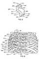
- FIGS. 4A and 4Bfurther depict an embodiment of an intercostal spacer system according to an aspect of the present invention, that includes a plurality of intercostal spacer devices 100 in use within the rib cage to correct a spinal deformity of a patient.
- Multiple intercostal spacer devices 100are inserted into the intercostal spaces of adjacent ribs 30 at corresponding affected spinal levels.
- Adjacent intercostal spacer devices 100are preferably implanted in close association relative to each other, resulting in an overall generally linear arrangement of the system as shown in FIG. 4A .
- intercostal spacer device 100when implanted, the shape and size of intercostal spacer device 100 allows for inferior pair of arms 117 of an upper placed intercostal spacer device 100 to be positioned proximate or within the space defined between the two superior pair of arms 114 of an adjacent lower placed intercostal spacer device 100.
- each of the plurality of intercostal spacer devices 100may be secured within the intercostal space with at least one connector 40, 41 (not shown).
- at least one connector 40may link or couple each of the plurality of intercostal spacer devices 100 to each other (not shown).
- the number of intercostal spacer devices 100 implantedis dependent upon the severity of the spinal deformity and the affected levels of the spinal column.
- FIG. 4Cthree intercostal spacer devices 100 are shown to be used to correct a spinal deformity that spans four levels of the spinal column.
- FIG. 5depicts still another alternative embodiment of an intercostal spacer device 200.
- Intercostal spacer device 200includes a spacer member 210 comprising a superior end 212 and an inferior end 213 with a central axis (not shown) extending between superior end 212 and inferior end 213. Extending in an upward direction from superior end 212 is preferably one pair of arms 214 including an anterior arm 215 and a posterior arm 216. Further, extending in a downward direction from inferior end 213 is preferably one pair of arms 217 that may include an anterior arm 218 and a posterior arm 219.
- Each pair of arms 214, 217are integral to spacer member 210 usually with superior pair of arms 214 being offset laterally relative to the central axis and inferior pair of arms 217 being preferably offset medially relative to the central axis. It is contemplated, that an alternative configuration of intercostal spacer device 200 may include each pair of arms 214, 217 to be opposite as described previously, in that superior pair of arms 214 being offset medially relative to the central axis and inferior pair of arms 217 being offset laterally relative to the central axis.
- An upper channel 220is typically defined by a seat 222, anterior arm 215 and posterior arm 216. Additionally, for inferior pair of arms 217, a lower channel 221 is defined by a seat 223, anterior arm 218 and posterior arm 219.
- Anterior arm 215 and posterior arm 216are disposed relatively parallel to each other and project in a generally upward direction from seat 222.
- Inferior pair of arms 217, anterior arm 218 and posterior arm 219project in a generally downward direction from seat 223 and are substantially parallel to each other.
- Each pair of arms 214, 217, together with seats 222, 223form U-shaped channels 220, 221 respectively, which are each appropriately sized to receive a rib 30.
- connector 40, 41may be utilized with intercostal spacer device 200 to secure intercostal spacer device 200 within an intercostal space.
- connector 40may be positioned through anterior to posterior directed, single or multiple, straight or angled holes (not shown) within spacer member 210, thereby allowing connector 40 to wrap or loop around or over superior pair of arms 214 and inferior pair of arms 217 allowing for securement of intercostal spacer device 200 within the intercostal space in the same or similar manner as described for intercostal spacer device 10.
- connector 41may be inserted through anterior to posterior directed, single or multiple straight holes or passages (not shown) within superior pair of arms 214 and inferior pair of arms 217.
- the hole or passage located in superior pair of arms 214being substantially parallel to the hole located in inferior pair of arms 217.
- connector 41preferably will be inserted through the hole or passage that is located in the upper most portion of superior pair of arms 214 and span upper channel 220 and across the superior margin of rib 30.
- a second connector 41may be inserted through a hole or passage located in the downward most portion of inferior set of arms 217 and span lower channel 221 and across the inferior margin of rib 30.
- intercostal spacer device 200when used in the rib cage, intercostal spacer device 200 is placed within an intercostal space.
- intercostal spacer device 200is maneuvered in a manner allowing two adjacent ribs 30 to be positioned within each of the upper channel 220 and lower channel 221, causing the anterior aspect of two adjacent ribs 30 to contact anterior arms 215, 218 and the posterior aspect of two adjacent ribs 30 to contact posterior arms 216, 219.
- Upper channel 220 and lower channel 221are sized and configured to provide resistance to any in vivo forces that may dislodge intercostal spacer device 200 from its position within the intercostal space.
- FIGS. 6 and 7further depict an alternative embodiment of an intercostal spacer system which includes a plurality of intercostal spacer devices 200 in use within the rib cage to correct a spinal deformity of a patient.
- Multiple intercostal spacer devices 200are inserted into the intercostal spaces of adjacent ribs 30 at corresponding affected spinal levels.
- Adjacent intercostal spacer devices 200are preferably implanted in close approximation relative to each other, resulting in an overall generally linear arrangement of the system.
- the shape and size of intercostal spacer device 200allows for inferior pair of arms 217 of an upper intercostal spacer device 200 to either contact or be proximate to spacer member 210 of the adjacent and lower intercostal spacer device 200.
- each of the plurality of intercostal spacer devices 200may be secured within the intercostal space with at least one connector 40, 41 (not shown). Alternatively, at least one connector 40 may link or couple each of the plurality of intercostal spacer devices 200 to each other (not shown).
- the number of intercostal spacer devices 200 implantedis dependent upon the severity of the spinal deformity and the affected levels of the spinal column.
- three intercostal spacer devices 200are used to correct a spinal deformity that spans four levels of the spinal column.
- the intercostal spacer device 10, 100, 200can be fabricated from materials that are flexible or exhibit at least some flexibility. Additionally, the intercostal spacer device 10, 100, 200 may be fabricated from materials that are resilient and/or elastic, so it can assume various shapes during and after insertion and securement within the intercostal space.
- the intercostal spacer device 10, 100, 200can be made from any biocompatible material, material of synthetic or natural origin, and material of a resorbable or non-resorbable nature.
- construct materialinclude resorbable materials including polylactide, polyglycolide, tyrosine-derived polycarbonate, polyanhydride, polyorthoester, polyphosphazene, calcium phosphate, hydroxyapatite, bioactive glass, collagen, albumin, fibrinogen and combinations thereof; and non-resorbable materials including polyethylene, polyester, polyvinyl alcohol, polyacrylonitrile, polyamide; polytetrafluorethylene, poly-paraphenylene terephthalamide, polyetheretherketone, poly urethane, and combinations thereof.
- Non-resorbable materialsmay include carbon-reinforced polymer composites, shape-memory alloys, titanium, titanium alloys, cobalt chrome alloys, stainless steel, and combinations thereof.
- the intercostal spacer device 10, 100, 200is preferably fabricated from material capable of resisting compressive motion (or loads) with a stiffness of about 10 to about 300 N/mm (newtons per millimeter).
- the method for correcting a spinal deformityincludes, providing at least one intercostal spacer device 10, intercostal spacer device 10 includes spacer member 11 comprising superior end 12 and inferior end 13 with a central axis (not shown) extending between superior end 12 and inferior end 13. Extending outward from superior end 12 is preferably at least one superior pair of arms 14 that may include anterior arm 15 and posterior arm 16. Further, extending outward from inferior end 13 is preferably one superior pair of arms 17 that may include anterior arm 18 and posterior arm 19. Each pair of arms 14, 17 are integral to spacer member 11.
- An upper channel 20is typically defined by seat 22, anterior arm 15 and posterior arm 16. Additionally, a lower channel 21 is defined by seat 23, anterior arm 18 and posterior arm 19.
- Each pair of arms 14, 17, together with seats 22, 23form U-shaped channels 20, 21 which are each appropriately sized to receive a rib 30.
- the methodfurther includes preferably positioning intercostal spacer device 10 within the intercostal space between two adjacent ribs 30.
- the intercostal spacer device 10is maneuvered in a manner that typically results in the positioning of a first rib 30 into upper channel 20 between superior pair of arms 14 and a second rib 30 into lower channel 21 between inferior pair of arms 17.
- Placement of ribs 30 within upper and lower channels 20, 21secures intercostal spacer device 10 within the patient's rib cage and produces a compressive or distraction force, depending on the spinal curvature geometry, for correcting a spinal deformity.
- the methodmay include inserting connectors 40, 41 into each of the intercostal spacer devices 10 following implantation into the intercostal space.
- at least one connector 40may be utilized with each individual intercostal spacer device 10 or alternatively, at least one connector 40 may link or couple the plurality of intercostal spacer devices to each other. It is contemplated herein that the steps of the method for connecting a spinal deformity are analogous to those that may be used with intercostal spacer device 100 and intercostal spacer device 200 described herein.
- FIGS. 8, 9, 10 and 11show a further alternative embodiment of the intercostal spacer device 400 that can be formed in situ during a surgical procedure.
- Intercostal spacer device 400includes the following basic aspects: a flexible container 402 and a structure 404 for at least part of flexible container 402 that controls at least part of the shape of intercostal spacer device 400.
- Flexible container 402can be filled or injected through optional conduit 406 after placement.
- structure 404may be folded or otherwise reduced in size prior to use in some aspects. Together with an unfilled container 402, in some aspects, intercostal spacer device 400 can create a smaller footprint during implantation. Once filled, structure 404 provides support and containment for the flexible container 402, as well as providing shape control for at least part of intercostal spacer device 400.
- FIG. 8depicts a partially cut-away view of intercostal spacer device 400.
- intercostal spacer device 400comprises an unfilled flexible container 402 inside structure 404.
- flexible container 402is in an evacuated state during implantation and prior to being filled.
- a valvee.g., a one-way valve
- structure 404is outside flexible container 402.
- flexible container 402can be outside structure 404, or flexible container 402 and structure 404 can be integrated.
- structure 404is shown to be roughly H-shaped to fit between adjacent ribs 30, structure 404 may have any shape necessary for the particular surgical application.
- structure 404could instead have a roughly cylindrical shape to replace an intervertebral disc.
- structure 404could be spherically or elliptically shaped to replace part of the intervertebral disc, for example, the nucleus pulpous, leaving the rest of the disc intact.
- structure 404is shown enveloping the flexible container 402, structure 404 could be for only a portion of flexible container 402, depending on the particular application. For example, it may be desired to prevent bulging of flexible container 402 only in a particular area.
- Coupled to flexible container 402is optional conduit 406 for accepting a material that is compressible following implantation.
- Structure 404provides support for and containment of flexible container 402, when filled.
- Flexible container 402is flexible and substantially impermeable to the material it will be filled with. However, depending on the application, flexible container 402 may be permeable to other materials, for example, it may be air and/or water permeable. In the present example, flexible container 402 takes the form of a bag or balloon, but can take other forms, so long as flexible and substantially impermeable to the material it will be filled with. Thus, flexible container 402 must be substantially impermeable to the injectable material, for example, in a liquid state during filling and prior to curing. Examples of container materials include silicone, rubber, polyurethane, polyethylene terephthalate (PET), polyolefin, polycarbonate urethane, and silicone copolymers.
- Conduit 406accepts the injectable material being used to fill flexible container 402.
- conduit 406comprises a one-way valve, however, a two-way valve is also contemplated, as another example.
- Conduit 406can comprise any material suitable for implanting, for example, various plastics.
- conduit 406is constructed to be used with a delivery system for filling flexible container 402, such as, for example, a pressurized syringe-type delivery system. However, the delivery system itself forms no part of the present invention. It is contemplated that, conduit 406 may be optional.
- Examples of how to fill flexible container 402comprise the use of a self-sealing material for flexible container 402, or leaving an opening in flexible container 402 that is closed (e.g., sewn shut) intraoperatively after filling.
- Using a curable material to fill flexible container 402may also serve to self-seal flexible container 402.
- flexible container 402is filled with an injectable material that is compressible following implantation between two adjacent ribs of a patient.
- the compressibility characteristicensures that the injected material exhibits viscoelastic behavior and that, along with structure 404, the intercostal spacer device 400 can accept compressive loads.
- intercostal spacer device 400may be capable of resisting compressive motion (or loads) with a stiffness of about 10 to about 300 N/mm (newtons per millimeter).
- the materialis preferably injectable, and may be compressible immediately or after a time, for example, after curing.
- the compressibility characteristicis necessary during end use, i.e., after implantation.
- Materials that could be usedinclude, for example, a plurality of beads (e.g., polymer beads) that in the aggregate are compressible, or materials that change state from exhibiting fluid properties to exhibiting properties of a solid or semi-solid.
- state-changing materialsinclude two-part curing polymers and adhesive, for example, platinum-catalyzed silicone, epoxy or polyurethane.
- structure 404provides support for and containment of container 402 when filled, as well as at least partial shape control of intercostal spacer device 400.
- Structure 404comprises, for example, a structural mesh comprising a plurality of fibers and/or wires 408. Within the structural mesh are shape-control fibers and/or wires 410.
- shape controlis provided by wires of a shape-memory alloy (e.g., Nitinol). Shape-memory alloy wire(s) 410 can be coupled to the structural mesh (inside or outside), or weaved into the mesh (i.e., integrated). Coupling can be achieved, for example, by stitching, twisting, or closing the wire on itself.
- a shape-memory alloye.g., Nitinol
- Shape-memory alloy wire(s) 410can be coupled to the structural mesh (inside or outside), or weaved into the mesh (i.e., integrated). Coupling can be achieved, for example, by stitching, twisting, or
- shape controlcan be provided by other wires or fibers that do not "give" in a particular direction, for example, metal or metal alloys (e.g., tantalum, titanium or steel, and non-metals, for example, carbon fiber, PET, polyethylene, polypropylene, etc.).
- the shape-memory alloycan be passive (e.g., elastic) or active (e.g., body-temperature activated).
- the use of metal, metal alloy or barium coated wires or fiberscan also improve radiopacity for imaging.
- the remainder of structure 404can take the form of, for example, a fabric jacket, as shown in FIG. 8 .
- the fabric jacket in this examplecontains and helps protect flexible container 402 from bulging and damage from forces external to flexible container 402, while the shape-memory alloy provides shape control of intercostal spacer device 400 in a center region 412.
- the fibers of the jacketcomprise, for example, PET fabric, polypropylene fabric, polyethylene fabric and/or steel, titanium or other metal wire.
- structure 404may be permeable to a desired degree. For example, if bone or tissue growth is desired to attach to structure 404, permeability to the tissue or bone of interest would be appropriate.
- permeability of structure 404may be desired to allow the material used to fill flexible container 402 to evacuate air or water, for example, from flexible container 402, in order to prevent bubbles from forming inside.
- a meshfor example, the degree of permeability desired can be achieved by loosening or tightening the weave.
- structure 404is shown in a roughly H-shape in the example of FIG. 8 , it will be understood that in practice, structure 404 can be made to be folded, unexpanded, or otherwise compacted. This is particularly true where, for example, structure 404 comprises a fabric or other easily folded material. A folded or unexpanded state facilitates implantation, allowing for a smaller surgical opening, and unfolding or expansion in situ upon filling of flexible container 402. Further, structure 404 can have a different final shape, depending on the shape-control material used. For example, the shape-memory wires in FIG. 8 may be in their inactive state, whereupon activation by body temperature causes contraction thereof, making the spacer of FIG. 8 "thinner" than shown in center region 412.
- FIG. 9depicts an outer view of another example of an intercostal spacer device 500.
- a flexible container conduit 501is shown pointing outward from an opening 503.
- the structure 502delimits the final shape of intercostal spacer device 500.
- Structure 502comprises a mesh 504 of shape-memory alloy wire, that is soaked through with a dispersion polymer 506 (e.g., silicone).
- the dispersion polymer(after curing) acts as the flexible container and is shown filled in FIG. 9 .
- Thisis one example of the flexible container and structure 502 being integral.
- mesh 504 of FIG. 9is described as being all shape-memory alloy wire, it will be understood that, like FIG. 8 , the shape-memory alloy could only form a part of structure 502.
- FIG. 10is a cross-sectional view of another example of an intercostal spacer device 600.
- Intercostal spacer device 600is similar to intercostal spacer device 500 of FIG. 9 , except that instead of being soaked in a dispersion polymer, a structural mesh 602 of a shape-memory alloy wire is coated with a dispersion polymer (e.g., silicone) 604 or other curable liquid appropriate for the container material, creating an outer flexible container.
- a dispersion polymere.g., silicone
- the coatingcan be done in a conventional manner, for example, by dip molding on the outside of the mesh.
- FIG. 11depicts yet another example of an intercostal spacer device 800 with an integrated flexible container and structure.
- the flexible container and structure in the example of FIG. 11both comprise a single layer 802 of rubber that is thick enough for a given application to perform the functions of both the flexible container and structure (including shape control). Such a rubber shell would be able to return to its original shape when unconstrained.
- intercostal spacer device 800preferably includes a conduit 804 (preferably, a one-way valve) for filling the internal space 806.
- the injectable materialcan be any of the filling materials described above, for example, silicone.
- the rubber shell 802 of FIG. 11can be augmented with internal, external, or integrated features to further control shape.
- featuresinclude thread, wires (e.g., metal, including shape-memory alloys), cables, tethers, rings or a mesh.
- the method for correcting a spinal deformity utilizing an alternative embodiment of the intercostal spacer deviceincludes, providing at least one intercostal spacer device 400, the intercostal device 400 includes a flexible container 402 used to contain an injectable material, with flexible container 402 being preferably impermeable to the injectable material, a conduit 406 coupled to flexible container 402 for receiving the injectable material and a structure 404, that controls at least part of flexible container 402 after injectable material is injected through conduit 406 and into flexible container 402.
- Structure 404has a shape that is sized and configured for placement between two adjacent ribs of a patient.
- the methodpreferably provides for intercostal spacer device 400 to be implanted into the intercostal space between two adjacent ribs.
- the methodwould also typically include injecting the injectable material preferably through conduit 406 into flexible container 402, the injectable material being compressible following intercostal spacer device 400 implantation between two adjacent ribs.
- the compressibility characteristicensures that the injectable material exhibits viscoelastic behavior and that, along with structure 404, the intercostal spacer device 400 can accept compressive loads and produce distraction forces for correcting a spinal deformity within a patient.
Landscapes
- Health & Medical Sciences (AREA)
- Orthopedic Medicine & Surgery (AREA)
- Life Sciences & Earth Sciences (AREA)
- Surgery (AREA)
- Neurology (AREA)
- Heart & Thoracic Surgery (AREA)
- General Health & Medical Sciences (AREA)
- Biomedical Technology (AREA)
- Nuclear Medicine, Radiotherapy & Molecular Imaging (AREA)
- Medical Informatics (AREA)
- Molecular Biology (AREA)
- Animal Behavior & Ethology (AREA)
- Engineering & Computer Science (AREA)
- Public Health (AREA)
- Veterinary Medicine (AREA)
- Prostheses (AREA)
- Surgical Instruments (AREA)
- Position Fixing By Use Of Radio Waves (AREA)
- Radar Systems Or Details Thereof (AREA)
Abstract
Description
- The present invention relates generally to orthopaedic implants used for the correction of spinal deformities, and more specifically, but not exclusively, concerns apparatuses placed within the intercostal space of two ribs to allow for deformity correction or healing of the spinal column.
- To secure and treat spinal deformities, including scoliosis, it is a generally accepted practice to place implants adjacent to or into the vertebrae to produce loads for correcting an abnormal curvature of the spine and to maintain appropriate vertebral support for the healing of the implanted bone fusion material.
- Typical spinal implant systems are implanted through a posterior approach to the spinal column and utilize a rod as the support and stabilizing element connected to a series of two or more bone fasteners that have been inserted into two or more vertebrae. The connections between these components are then secured, thereby fixing a supporting construct to multiple levels in the spinal column.
- Advancement of the state of orthopaedic implants and the treatment of pediatric and adolescent scoliosis is believed to be desirable. The present invention satisfies the need for improvements to the surgical treatment by providing a more mechanically efficient intercostal spacer device for implantation into multiple intercostal spaces of a patient's rib cage. The intercostal spacer device is a one piece construct fabricated from a biocompatible material. Alternatively, the intercostal spacer device may be a multiple piece construct that includes a flexible container that is fillable in situ to a desired amount, with a structure for at least part of the container providing shape control of the intercostal spacer device. An optional conduit coupled to the container allows for filling of the container, for example, by injecting a material into the container.
- The invention is defined in the appended claims.
- There is provided in one aspect, an intercostal spacer device. The intercostal spacer device includes a spacer member that has a superior end and an inferior end. Extending from both the superior end and inferior end are at least one pair of arms with a channel defined between each pair of arms. The spacer member is sized and configured to enable placement of the spacer member within an intercostal space, with each channel being sized to receive a rib allowing the intercostal spacer device to resist dislodgement from the ribs and produce a force for correcting a spinal deformity.
- There is provided in another aspect, an intercostal spacer device that includes a flexible container for receiving an injectable material that is compressible following implantation between two adjacent ribs, wherein the flexible container is substantially impermeable to the injectable material. The intercostal spacer device further includes a conduit coupled to the flexible container for accepting the injectable material, and a structure for at least part of the flexible container when containing the material, wherein the structure has a shape to fit between two adjacent ribs.
Also described herein is a method of controlling at least part of the shape of the intercostal spacer device. The intercostal spacer device has a flexible container for containing an injectable material that is compressible following implantation, wherein the container is substantially impermeable to the injectable material. The intercostal spacer device further includes a structure for at least part of the flexible container. The method provides for creating the structure with at least one material for controlling at least part of the shape of the intercostal spacer device following implantation into the intercostal space. - There is also provided in yet another aspect, an intercostal spacer system. The intercostal spacer system includes a plurality of intercostal spacer devices, with each of the intercostal spacer devices having a spacer member that has a superior end and an inferior end. Extending from both the superior end and inferior end are at least one pair of arms with a channel being defined between each pair of arms. The spacer member is sized and configured to enable placement of the member within an intercostal space, with each channel being sized to receive a rib, allowing the intercostal spacer device to resist dislodgement from the ribs when implanted. Following implantation, the plurality of intercostal spacer devices cooperate to dynamically produce a force for correcting a spinal deformity within a patient.
- Also described herein is a method of correcting a spinal deformity. The method includes the step of providing at least one intercostal spacer device, the intercostal spacer device includes a spacer member having first and second ends with at least one pair of arms extending from each of the first and second ends. The spacer member, the first pair of arms extending from the first end and the second pair of arms extending from the second end of the at least one intercostal spacer are sized for placement between a first rib and an adjacent second rib of a patient. The method further includes the positioning of the at least one intercostal spacer device into the intercostal space between the two adjacent ribs of the patient with the first rib disposed between the first pair of arms and the adjacent second rib disposed between the second pair of arms and thus securing the intercostal spacer device within the intercostal space and producing a force to correct the spinal deformity of the patient.
- Also described herein is a method of correcting a spinal deformity. The method includes providing an intercostal spacer device, the intercostal spacer device includes a flexible container for containing an injectable material that is compressible following implantation, wherein the flexible container is substantially impermeable to the injectable material. The intercostal spacer device further includes a conduit coupled to the flexible container for accepting the injectable material, and a structure for at least part of the flexible container when containing the material, wherein the structure has a shape of the intercostal spacer device that is sized and configured to fit between adjacent ribs in a patient. The method further includes implanting the intercostal spacer device between two adjacent ribs. The injectable material is then injected into the flexible container through the conduit such that the shape of the structure is achieved, thus producing a force to correct the spinal deformity of the patient.
- Further, additional features and advantages are realized through the techniques of the present invention. Other embodiments and aspects of the invention are described in detail herein and are considered a part of the claimed invention.
- The subject matter which is regarded as the invention is particularly pointed out and distinctly claimed in the claims at the conclusion of the specification. The foregoing and other objects, features and advantages of the invention are apparent from the following detailed description taken in conjunction with the accompanying drawings in which:
FIG. 1A is a side elevational view of one embodiment of an intercostal spacer device shown disposed between the cross-section of two adjacent ribs.FIG. 1B is a side elevational view of one embodiment of an intercostal spacer device with two single connectors shown disposed between the cross-section of two adjacent ribs;FIG. 1C is a side elevational view of one embodiment of an intercostal spacer device shown disposed between the cross-section of two adjacent ribs, with a single connector surrounding the entire intercostal spacer device;FIG. 1D is a side elevational view of one embodiment of an intercostal spacer device, shown disposed between the cross-section of two adjacent ribs, with a single connector utilizing an alternative securing configuration;FIG. 1E is a side elevational view of one embodiment of an intercostal spacer device shown disposed between the cross-section of two adjacent ribs, with two alternative single connectors inserted through two bore holes;FIG. 1F is a perspective view of the intercostal spacer device embodiment ofFIG. 1E with the two alternative single connectors extracted from the two bore holes;FIG. 2 is a posterior elevational view of one embodiment of an intercostal spacer system implanted in the posterior aspect of the rib cage;FIG. 3 is a perspective view of one embodiment of an intercostal spacer device, in accordance with an aspect of the present invention;FIG. 4A is a posterior elevational view of one embodiment of an intercostal spacer system shown disposed between three ribs, in accordance with an aspect of the present invention;FIG. 4B is a cross-section side elevational view of the intercostal spacer device system ofFIG. 4A taken alongline 4B-4B shown disposed between the cross-section of four adjacent ribs, in accordance with an aspect of the present invention;FIG. 4C is a posterior perspective view of one embodiment of an intercostal spacer system shown disposed between four adjacent ribs, in accordance with an aspect of the present invention;FIG. 5 is a perspective view of one embodiment of an intercostal spacer device;FIG. 6 is a posterior elevational view of one embodiment of an intercostal spacer system implanted in the posterior aspect of the rib cage;FIG. 7 is a posterior elevational view of one embodiment of an intercostal spacer device system shown disposed between four adjacent ribs;FIG. 8 is a perspective partial cut-away view of one embodiment of an unfilled intercostal spacer device with the container in the structure;FIG. 9 is a posterior elevational view of one embodiment of an intercostal spacer device with an integrated container and structure;FIG. 10 is a cross-sectional elevational view of one embodiment of an intercostal spacer device with an external container; andFIG. 11 depicts another embodiment of an intercostal spacer device with an integrated container and structure.- The description below in relation to
Figs 1A-1F ,2 and5-11 does not form part of the claimed invention but is provided by way of useful background information to aid understanding. - As depicted in
FIG.1A , the general arrangement of anintercostal spacer device 10 includes aspacer member 11 comprising asuperior end 12 and aninferior end 13 with a central axis (not shown) extending betweensuperior end 12 andinferior end 13. Extending in an upward direction fromsuperior end 12 is preferably one pair ofarms 14 that may include ananterior arm 15 and aposterior arm 16. Further, extending in a downward direction frominferior end 13 is preferably one pair ofarms 17 that may include ananterior arm 18 and aposterior arm 19. Each pair ofarms spacer member 11 and are sized to resist dislodgement ofintercostal spacer device 10 following placement within the intercostal space. Further, each pair ofarms spacer member 11 resulting in a roughly H-shaped overall structure. Anupper channel 20 is typically defined by aseat 22,anterior arm 15 andposterior arm 16. Additionally, alower channel 21 is defined by aseat 23,anterior arm 18 andposterior arm 19.Anterior arm 15 andposterior arm 16 are disposed relatively parallel to each other and project in an upward manner fromseat 22.Anterior arm 18 andposterior arm 19 project in a downward manner fromseat 23 and are substantially parallel to each other. Each pair ofarms seats U-shaped channels rib 30. When in use in the rib cage,intercostal spacer device 10 is placed within an intercostal space. Preferably,intercostal spacer device 10 is maneuvered in a manner allowing twoadjacent ribs 30 to be positioned withinchannels adjacent ribs 30 to contactanterior arms adjacent ribs 30 to contactposterior arms - With reference to
FIGS. 1B, 1C, 1D ,1E and 1F ,intercostal spacer device 10 includes aspacer member 11 comprising asuperior end 12 and aninferior end 13. Extending in an upward direction fromsuperior end 12 is preferably one pair ofarms 14 that may include ananterior arm 15 and aposterior arm 16. Further, extending in a downward direction frominferior end 13 is preferably one pair ofarms 17 that may include ananterior arm 18 and aposterior arm 19. Anupper channel 20 is typically defined by aseat 22,anterior arm 15 andposterior arm 16. Additionally, alower channel 21 is defined by aseat 23,anterior arm 18 andposterior arm 19. Each pair ofarms seats U-shaped channels rib 30. Typically, at least one throughhole 24 is directed in the anterior to posterior direction and located withinspacer member 11 in theintercostal spacer device 10. In one approach, connector 40 (seeFIG. 1B ) is inserted intohole 24 following the placement ofintercostal spacer device 10 betweenadjacent ribs 30. As depicted inFIG. 1B , afirst connector 40 may be inserted through passage orhole 24 that extends from ananterior surface 31 ofspacer member 11 to aposterior surface 32 of spacer member and then wraps over the superior surface ofrib 30 which is positioned withinupper channel 20. Asecond connector 40 may be inserted through a second passage orhole 24 that extends fromanterior surface 31 ofspacer member 11 toposterior surface 32 ofspacer member 11 and then wraps over the inferior surface of a secondadjacent rib 30 which is positioned withinlower channel 21. The ends ofconnectors 40 may be secured using crimps, knots, ties or other suitable fasteners. It is understood to those skilled in the art that other securement techniques and configurations are contemplated and will depend on the type ofconnector 40 used withinintercostal spacer device 10. - As shown in
FIG. 1C , an alternative method of securingintercostal spacer device 10 within the intercostal space may include extending at least oneconnector 40 around the circumference of the exterior surface ofintercostal spacer device 10 and the twoadjacent ribs 30. The ends ofconnector 40 may be then be secured using crimps, knots, ties or other suitable fasteners, although it is understood to those skilled in the art that other securement techniques and configurations are contemplated and will depend on the type ofconnector 40 used in securingintercostal spacer device 10 within the intercostal space. - As seen in
FIG. 1D , another alternative method of securingintercostal spacer device 10 within the intercostal space is contemplated.FIG. 1D depicts the use of at least oneconnector 40 typically utilizing a figure-8 configuration. A single ormultiple connector 40 may be inserted through an angled passage orhole 25 that extends fromanterior surface 31 ofspacer member 11 toposterior surface 32 ofspacer member 11 and then looped over the superior surface ofrib 30 which is positioned withinupper channel 20.Connector 40 is further passed through a second angled passage orhole 25 that extends fromanterior surface 31 ofspacer member 11 toposterior surface 32 of spacermember allowing connector 40 to also loop over the inferior surface of a secondadjacent rib 30 which is positioned withinlower channel 21. The two ends ofconnector 40 may be secured using crimps, knots, ties or other suitable fastener. It is understood to those skilled in the art that other securement techniques and configurations are contemplated and will depend on the type ofconnector 40 used withinintercostal spacer device 10.Connector 40 may be in the form of a wire, cable, tether, belt, band, cord or other suitable structure for securement within the intercostal space and may be fabricated from a material selected from the group consisting of carbon fiber composite polymers, bio-compatible metals, resorbable polymers, bio-inert polymeric materials, and any combinations of these materials. - Another alternative method for securing
intercostal spacer device 10 within the intercostal space is seen atFIGS. 1E and 1F . As shown,intercostal spacer device 10 includes aspacer member 11 comprising asuperior end 12 and aninferior end 13. Extending in an upward direction fromsuperior end 12 is preferably one pair ofarms 14, includinganterior arm 15 andposterior arm 16. Further, extending in a downward direction frominferior end 13 is preferably one pair ofarms 17 that may includeanterior arm 18 andposterior arm 19. As provided above,upper channel 20 is typically defined byseat 22,anterior arm 15 andposterior arm 16. Additionally,lower channel 21 is defined byseat 23,anterior arm 18 andposterior arm 19. Each pair ofarms seats U-shaped channels rib 30. Preferably, at least one throughhole 26 is directed in an anterior to posterior direction and passes throughanterior arms posterior arms arms 14 and inferior pair ofarms 17, respectively. As seen inFIG. 1E , at least onehole 26 extends through superior pair ofarms 14 and is substantially parallel to asecond hole 26 extending through inferior pair ofarms 17. In use,intercostal spacer device 10 is placed within an intercostal space and typically is maneuvered in a manner to allow twoadjacent ribs 30 to be positioned within upper andlower channels adjacent ribs 30 to contactanterior arms adjacent ribs 30 to contactposterior arms intercostal spacer device 10, a connector 41 (seeFIG. 1F ) is inserted intohole 26 following the placement ofintercostal spacer device 10 betweenadjacent ribs 30. As depicted inFIG. 1E , oneconnector 41 may be inserted throughhole 26 that is located in the most upper portion of superior pair ofarms 14 and spanupper channel 20 and across the superior margin ofrib 30. Preferably, asecond connector 41 is inserted through asecond hole 26 located in the most downward portion of inferior set ofarms 17 and spanlower channel 21 and across the inferior margin ofrib 30. The ends of the twoconnectors 41 may be secured using crimps, caps, nuts, rivets, or other suitable fastener device. It is understood to those skilled in the art that other securement techniques and configurations are contemplated and will depend on the type ofconnector 41 used withinintercostal spacer device 10.Connector 41 may be in the form of a bolt, screw, lock pin, rivet, staple, press-fit pin or other suitable structure for securement within the intercostal space and may be fabricated from a material selected from the group consisting of carbon fiber composite polymers, bio-compatible metals, resorbable polymers, bio-inert polymeric materials, and any combinations of these materials. FIG. 2 depicts an intercostal spacer system that includes a plurality ofintercostal spacer devices 10 placed within the rib cage to correct a spinal deformity of a patient. Multipleintercostal spacer devices 10 are inserted into the intercostal spaces of severaladjacent ribs 30 at corresponding deformed spinal levels. Adjacentintercostal spacer devices 10 are preferably implanted in an offset manner relative to each other, resulting in an overall generally staggered arrangement. As described previously, each of the plurality ofintercostal spacer devices 10 may be secured within the intercostal space with at least oneconnector 40, 41 (not shown). Alternatively, at least oneconnector 40 may link or couple each of the plurality ofintercostal spacer devices 10 to each other (not shown). Typically, the number ofintercostal spacer devices 10 implanted may be dependent upon the severity of the spinal deformity and the affected levels of the spinal column. By way of example only, inFIG. 2 , threeintercostal spacer devices 10 are placed on the concave side of a medial-lateral deformity that spans four levels of the spinal column.FIG. 3 depicts an embodiment of anintercostal spacer device 100 in accordance with an aspect of the present invention.Intercostal spacer device 100 includes aspacer member 110 comprising of asuperior end 112 and aninferior end 113 with a central axis (not shown) extending betweensuperior end 112 andinferior end 113. Extending in an upward direction fromsuperior end 112 is preferably two pair ofarms 114, with each pair of arms including ananterior arm 115 and aposterior arm 116. Further, extending frominferior end 113 in a downward direction is preferably one pair ofarms 117 that may include ananterior arm 118 and aposterior arm 119. Each pair ofarms spacer member 110 usually with one of the two superior pair ofarms 114 being offset laterally relative to the central axis and the second of the two superior pair ofarms 114 being offset medially relative to the central axis. The inferior pair ofarms 117 are preferably centered about the central axis resulting in a roughly Y-shaped overall structure definingintercostal spacer device 100. For each of superior pair ofarms 114, anupper channel 120 is typically defined by aseat 122,anterior arm 115 andposterior arm 116. Additionally, for inferior pair ofarms 117, alower channel 121 is defined by aseat 123,anterior arm 118 andposterior arm 119. For both superior pair ofarms 114,anterior arm 115 andposterior arm 116 are disposed relatively parallel to each other and project in a generally upward manner fromseat 122. For inferior pair ofarms 117,anterior arm 118 andposterior arm 119 project in a generally downward manner fromseat 123 and are substantially parallel to each other. Each pair ofarms seats U-shaped channels rib 30 and allowintercostal spacer device 100 to resist dislodgement following implantation within the rib cage.- Although not shown, it is contemplated that either
connector intercostal spacer device 100 to secureintercostal spacer device 100 within an intercostal space. As described above, it is contemplated thatconnector 40 may pass through anterior to posterior directed, single or multiple, straight or angled holes or passages (not shown) withinspacer member 110, thereby allowingconnector 40 to wrap or loop around or over both superior pair ofarms 114 and inferior pair ofarms 117 allowing for securement ofintercostal spacer device 100 within the intercostal space in the same or similar manner as described above forintercostal spacer device 10. Further, as discussed above, it is understood thatconnector 41 may be inserted through anterior to posterior directed, single or multiple straight holes or passages (not shown) within both superior pair ofarms 114 and inferior pair ofarms 117. The holes located in both superior pair ofarms 114 being substantially parallel to the hole or passage located in inferior pair ofarms 117. When in use,connector 41 preferably will be inserted through the holes that are located in the upper most portion of both superior pair ofarms 114 and span eachupper channel 120 and across the superior margin ofrib 30. Additionally, asecond connector 41 may be inserted through a hole or passage located in the downward most portion of inferior set ofarms 117 and spanlower channel 121 crossing over the inferior margin ofrib 30. - As shown in
FIGS. 4A ,4B and 4C , when used in the rib cage,intercostal spacer device 100 is typically placed within an intercostal space. Preferably,intercostal spacer device 100 is maneuvered in a manner allowing twoadjacent ribs 30 to be positioned within twoupper channels 120 andlower channel 121, causing the anterior aspect of twoadjacent ribs 30 to contactanterior arms adjacent ribs 30 to contactposterior arms FIGS. 4A and4B further depict an embodiment of an intercostal spacer system according to an aspect of the present invention, that includes a plurality ofintercostal spacer devices 100 in use within the rib cage to correct a spinal deformity of a patient. Multipleintercostal spacer devices 100 are inserted into the intercostal spaces ofadjacent ribs 30 at corresponding affected spinal levels. Adjacentintercostal spacer devices 100 are preferably implanted in close association relative to each other, resulting in an overall generally linear arrangement of the system as shown inFIG. 4A . Preferably, when implanted, the shape and size ofintercostal spacer device 100 allows for inferior pair ofarms 117 of an upper placedintercostal spacer device 100 to be positioned proximate or within the space defined between the two superior pair ofarms 114 of an adjacent lower placedintercostal spacer device 100. As described previously, each of the plurality ofintercostal spacer devices 100 may be secured within the intercostal space with at least oneconnector 40, 41 (not shown). Alternatively, at least oneconnector 40 may link or couple each of the plurality ofintercostal spacer devices 100 to each other (not shown). Typically, the number ofintercostal spacer devices 100 implanted is dependent upon the severity of the spinal deformity and the affected levels of the spinal column. By way of example only, inFIG. 4C , threeintercostal spacer devices 100 are shown to be used to correct a spinal deformity that spans four levels of the spinal column.FIG. 5 depicts still another alternative embodiment of anintercostal spacer device 200.Intercostal spacer device 200 includes aspacer member 210 comprising asuperior end 212 and aninferior end 213 with a central axis (not shown) extending betweensuperior end 212 andinferior end 213. Extending in an upward direction fromsuperior end 212 is preferably one pair ofarms 214 including ananterior arm 215 and aposterior arm 216. Further, extending in a downward direction frominferior end 213 is preferably one pair ofarms 217 that may include ananterior arm 218 and aposterior arm 219. Each pair ofarms spacer member 210 usually with superior pair ofarms 214 being offset laterally relative to the central axis and inferior pair ofarms 217 being preferably offset medially relative to the central axis. It is contemplated, that an alternative configuration ofintercostal spacer device 200 may include each pair ofarms arms 214 being offset medially relative to the central axis and inferior pair ofarms 217 being offset laterally relative to the central axis. Anupper channel 220 is typically defined by aseat 222,anterior arm 215 andposterior arm 216. Additionally, for inferior pair ofarms 217, alower channel 221 is defined by aseat 223,anterior arm 218 andposterior arm 219.Anterior arm 215 andposterior arm 216 are disposed relatively parallel to each other and project in a generally upward direction fromseat 222. Inferior pair ofarms 217,anterior arm 218 andposterior arm 219 project in a generally downward direction fromseat 223 and are substantially parallel to each other. Each pair ofarms seats U-shaped channels rib 30.- Although not shown, as discussed above, it is contemplated that either
connector intercostal spacer device 200 to secureintercostal spacer device 200 within an intercostal space. As described previously, it is contemplated thatconnector 40 may be positioned through anterior to posterior directed, single or multiple, straight or angled holes (not shown) withinspacer member 210, thereby allowingconnector 40 to wrap or loop around or over superior pair ofarms 214 and inferior pair ofarms 217 allowing for securement ofintercostal spacer device 200 within the intercostal space in the same or similar manner as described forintercostal spacer device 10. Further, as discussed above, it is understood thatconnector 41 may be inserted through anterior to posterior directed, single or multiple straight holes or passages (not shown) within superior pair ofarms 214 and inferior pair ofarms 217. The hole or passage located in superior pair ofarms 214 being substantially parallel to the hole located in inferior pair ofarms 217. When in use,connector 41 preferably will be inserted through the hole or passage that is located in the upper most portion of superior pair ofarms 214 and spanupper channel 220 and across the superior margin ofrib 30. Additionally, asecond connector 41 may be inserted through a hole or passage located in the downward most portion of inferior set ofarms 217 and spanlower channel 221 and across the inferior margin ofrib 30. - As shown in
FIGS. 6 and7 , when used in the rib cage,intercostal spacer device 200 is placed within an intercostal space. Preferably,intercostal spacer device 200 is maneuvered in a manner allowing twoadjacent ribs 30 to be positioned within each of theupper channel 220 andlower channel 221, causing the anterior aspect of twoadjacent ribs 30 to contactanterior arms adjacent ribs 30 to contactposterior arms Upper channel 220 andlower channel 221 are sized and configured to provide resistance to any in vivo forces that may dislodgeintercostal spacer device 200 from its position within the intercostal space. FIGS. 6 and7 further depict an alternative embodiment of an intercostal spacer system which includes a plurality ofintercostal spacer devices 200 in use within the rib cage to correct a spinal deformity of a patient. Multipleintercostal spacer devices 200 are inserted into the intercostal spaces ofadjacent ribs 30 at corresponding affected spinal levels. Adjacentintercostal spacer devices 200 are preferably implanted in close approximation relative to each other, resulting in an overall generally linear arrangement of the system. Preferably, when implanted, the shape and size ofintercostal spacer device 200 allows for inferior pair ofarms 217 of an upperintercostal spacer device 200 to either contact or be proximate tospacer member 210 of the adjacent and lowerintercostal spacer device 200. Additionally, when implanted, typically, superior pair ofarms 214 of lowerintercostal spacer device 200 will contact or be in close approximation tospacer member 210 of adjacent upperintercostal spacer device 200. As shown inFIG. 7 , following implantation,rib 30 may be simultaneously located withinlower channel 221 of a superior placedintercostal spacer device 200 andupper channel 220 of an inferior placedintercostal spacer device 200. As described previously, each of the plurality ofintercostal spacer devices 200 may be secured within the intercostal space with at least oneconnector 40, 41 (not shown). Alternatively, at least oneconnector 40 may link or couple each of the plurality ofintercostal spacer devices 200 to each other (not shown). Usually, the number ofintercostal spacer devices 200 implanted is dependent upon the severity of the spinal deformity and the affected levels of the spinal column. By way of example only, inFIG. 6 , threeintercostal spacer devices 200 are used to correct a spinal deformity that spans four levels of the spinal column.- With respect to the various embodiments of the
intercostal spacer device intercostal spacer device intercostal spacer device - The
intercostal spacer device intercostal spacer device - The method for correcting a spinal deformity includes, providing at least one
intercostal spacer device 10,intercostal spacer device 10 includesspacer member 11 comprisingsuperior end 12 andinferior end 13 with a central axis (not shown) extending betweensuperior end 12 andinferior end 13. Extending outward fromsuperior end 12 is preferably at least one superior pair ofarms 14 that may includeanterior arm 15 andposterior arm 16. Further, extending outward frominferior end 13 is preferably one superior pair ofarms 17 that may includeanterior arm 18 andposterior arm 19. Each pair ofarms spacer member 11. Anupper channel 20 is typically defined byseat 22,anterior arm 15 andposterior arm 16. Additionally, alower channel 21 is defined byseat 23,anterior arm 18 andposterior arm 19. Each pair ofarms seats U-shaped channels rib 30. The method further includes preferably positioningintercostal spacer device 10 within the intercostal space between twoadjacent ribs 30. Preferably, theintercostal spacer device 10 is maneuvered in a manner that typically results in the positioning of afirst rib 30 intoupper channel 20 between superior pair ofarms 14 and asecond rib 30 intolower channel 21 between inferior pair ofarms 17. Placement ofribs 30 within upper andlower channels intercostal spacer device 10 within the patient's rib cage and produces a compressive or distraction force, depending on the spinal curvature geometry, for correcting a spinal deformity. It is further understood that the method may include insertingconnectors intercostal spacer devices 10 following implantation into the intercostal space. Preferably, at least oneconnector 40 may be utilized with each individualintercostal spacer device 10 or alternatively, at least oneconnector 40 may link or couple the plurality of intercostal spacer devices to each other. It is contemplated herein that the steps of the method for connecting a spinal deformity are analogous to those that may be used withintercostal spacer device 100 andintercostal spacer device 200 described herein. FIGS. 8, 9, 10 and 11 show a further alternative embodiment of theintercostal spacer device 400 that can be formed in situ during a surgical procedure.Intercostal spacer device 400 includes the following basic aspects: aflexible container 402 and astructure 404 for at least part offlexible container 402 that controls at least part of the shape ofintercostal spacer device 400.Flexible container 402 can be filled or injected throughoptional conduit 406 after placement. Further,structure 404 may be folded or otherwise reduced in size prior to use in some aspects. Together with anunfilled container 402, in some aspects,intercostal spacer device 400 can create a smaller footprint during implantation. Once filled,structure 404 provides support and containment for theflexible container 402, as well as providing shape control for at least part ofintercostal spacer device 400.FIG. 8 depicts a partially cut-away view ofintercostal spacer device 400. As shown inFIG. 8 ,intercostal spacer device 400 comprises an unfilledflexible container 402 insidestructure 404. Preferably,flexible container 402 is in an evacuated state during implantation and prior to being filled. Where a valve (e.g., a one-way valve) is coupled toflexible container 402, withflexible container 402 preferably being evacuated prior to or during the process of coupling the valve thereto. In this embodiment,structure 404 is outsideflexible container 402. However, as will be described in more detail below,flexible container 402 can beoutside structure 404, orflexible container 402 andstructure 404 can be integrated. In addition, althoughstructure 404 is shown to be roughly H-shaped to fit betweenadjacent ribs 30,structure 404 may have any shape necessary for the particular surgical application. For example,structure 404 could instead have a roughly cylindrical shape to replace an intervertebral disc. As another example,structure 404 could be spherically or elliptically shaped to replace part of the intervertebral disc, for example, the nucleus pulpous, leaving the rest of the disc intact. Further, althoughstructure 404 is shown enveloping theflexible container 402,structure 404 could be for only a portion offlexible container 402, depending on the particular application. For example, it may be desired to prevent bulging offlexible container 402 only in a particular area. Coupled toflexible container 402 isoptional conduit 406 for accepting a material that is compressible following implantation.Structure 404 provides support for and containment offlexible container 402, when filled.Flexible container 402 is flexible and substantially impermeable to the material it will be filled with. However, depending on the application,flexible container 402 may be permeable to other materials, for example, it may be air and/or water permeable. In the present example,flexible container 402 takes the form of a bag or balloon, but can take other forms, so long as flexible and substantially impermeable to the material it will be filled with. Thus,flexible container 402 must be substantially impermeable to the injectable material, for example, in a liquid state during filling and prior to curing. Examples of container materials include silicone, rubber, polyurethane, polyethylene terephthalate (PET), polyolefin, polycarbonate urethane, and silicone copolymers.Conduit 406 accepts the injectable material being used to fillflexible container 402. Preferably,conduit 406 comprises a one-way valve, however, a two-way valve is also contemplated, as another example.Conduit 406 can comprise any material suitable for implanting, for example, various plastics. Also preferably,conduit 406 is constructed to be used with a delivery system for fillingflexible container 402, such as, for example, a pressurized syringe-type delivery system. However, the delivery system itself forms no part of the present invention. It is contemplated that,conduit 406 may be optional. Other examples of how to fillflexible container 402 comprise the use of a self-sealing material forflexible container 402, or leaving an opening inflexible container 402 that is closed (e.g., sewn shut) intraoperatively after filling. Using a curable material to fillflexible container 402 may also serve to self-sealflexible container 402.- In use,
flexible container 402 is filled with an injectable material that is compressible following implantation between two adjacent ribs of a patient. The compressibility characteristic ensures that the injected material exhibits viscoelastic behavior and that, along withstructure 404, theintercostal spacer device 400 can accept compressive loads. Preferably,intercostal spacer device 400 may be capable of resisting compressive motion (or loads) with a stiffness of about 10 to about 300 N/mm (newtons per millimeter). The material is preferably injectable, and may be compressible immediately or after a time, for example, after curing. For purposes of the invention, the compressibility characteristic is necessary during end use, i.e., after implantation. Materials that could be used include, for example, a plurality of beads (e.g., polymer beads) that in the aggregate are compressible, or materials that change state from exhibiting fluid properties to exhibiting properties of a solid or semi-solid. Examples of such state-changing materials include two-part curing polymers and adhesive, for example, platinum-catalyzed silicone, epoxy or polyurethane. - As noted above,
structure 404 provides support for and containment ofcontainer 402 when filled, as well as at least partial shape control ofintercostal spacer device 400.Structure 404 comprises, for example, a structural mesh comprising a plurality of fibers and/orwires 408. Within the structural mesh are shape-control fibers and/orwires 410. In one example, shape control is provided by wires of a shape-memory alloy (e.g., Nitinol). Shape-memory alloy wire(s) 410 can be coupled to the structural mesh (inside or outside), or weaved into the mesh (i.e., integrated). Coupling can be achieved, for example, by stitching, twisting, or closing the wire on itself. Alternatively, shape control can be provided by other wires or fibers that do not "give" in a particular direction, for example, metal or metal alloys (e.g., tantalum, titanium or steel, and non-metals, for example, carbon fiber, PET, polyethylene, polypropylene, etc.). The shape-memory alloy can be passive (e.g., elastic) or active (e.g., body-temperature activated). The use of metal, metal alloy or barium coated wires or fibers can also improve radiopacity for imaging. The remainder ofstructure 404 can take the form of, for example, a fabric jacket, as shown inFIG. 8 . Although the shape-memory alloy wires 410 make up only a portion of the structural mesh ofFIG. 8 , it will be understood that there could be more such wires, up to and including comprising the entirety of the mesh. The fabric jacket in this example contains and helps protectflexible container 402 from bulging and damage from forces external toflexible container 402, while the shape-memory alloy provides shape control ofintercostal spacer device 400 in acenter region 412. The fibers of the jacket comprise, for example, PET fabric, polypropylene fabric, polyethylene fabric and/or steel, titanium or other metal wire. Depending on the application,structure 404 may be permeable to a desired degree. For example, if bone or tissue growth is desired to attach to structure 404, permeability to the tissue or bone of interest would be appropriate. As another example, permeability ofstructure 404 may be desired to allow the material used to fillflexible container 402 to evacuate air or water, for example, fromflexible container 402, in order to prevent bubbles from forming inside. Where a mesh is used, for example, the degree of permeability desired can be achieved by loosening or tightening the weave. - Although
structure 404 is shown in a roughly H-shape in the example ofFIG. 8 , it will be understood that in practice,structure 404 can be made to be folded, unexpanded, or otherwise compacted. This is particularly true where, for example,structure 404 comprises a fabric or other easily folded material. A folded or unexpanded state facilitates implantation, allowing for a smaller surgical opening, and unfolding or expansion in situ upon filling offlexible container 402. Further,structure 404 can have a different final shape, depending on the shape-control material used. For example, the shape-memory wires inFIG. 8 may be in their inactive state, whereupon activation by body temperature causes contraction thereof, making the spacer ofFIG. 8 "thinner" than shown incenter region 412. FIG. 9 depicts an outer view of another example of anintercostal spacer device 500. Aflexible container conduit 501 is shown pointing outward from anopening 503. As shown, thestructure 502 delimits the final shape ofintercostal spacer device 500.Structure 502 comprises amesh 504 of shape-memory alloy wire, that is soaked through with a dispersion polymer 506 (e.g., silicone). The dispersion polymer (after curing) acts as the flexible container and is shown filled inFIG. 9 . This is one example of the flexible container andstructure 502 being integral. Althoughmesh 504 ofFIG. 9 is described as being all shape-memory alloy wire, it will be understood that, likeFIG. 8 , the shape-memory alloy could only form a part ofstructure 502.FIG. 10 is a cross-sectional view of another example of anintercostal spacer device 600.Intercostal spacer device 600 is similar tointercostal spacer device 500 ofFIG. 9 , except that instead of being soaked in a dispersion polymer, astructural mesh 602 of a shape-memory alloy wire is coated with a dispersion polymer (e.g., silicone) 604 or other curable liquid appropriate for the container material, creating an outer flexible container. The coating can be done in a conventional manner, for example, by dip molding on the outside of the mesh.FIG. 11 depicts yet another example of anintercostal spacer device 800 with an integrated flexible container and structure. The flexible container and structure in the example ofFIG. 11 both comprise asingle layer 802 of rubber that is thick enough for a given application to perform the functions of both the flexible container and structure (including shape control). Such a rubber shell would be able to return to its original shape when unconstrained. In addition,intercostal spacer device 800 preferably includes a conduit 804 (preferably, a one-way valve) for filling theinternal space 806. The injectable material can be any of the filling materials described above, for example, silicone.- In an alternate aspect, the
rubber shell 802 ofFIG. 11 can be augmented with internal, external, or integrated features to further control shape. Examples of such features include thread, wires (e.g., metal, including shape-memory alloys), cables, tethers, rings or a mesh. - The method for correcting a spinal deformity utilizing an alternative embodiment of the intercostal spacer device includes, providing at least one
intercostal spacer device 400, theintercostal device 400 includes aflexible container 402 used to contain an injectable material, withflexible container 402 being preferably impermeable to the injectable material, aconduit 406 coupled toflexible container 402 for receiving the injectable material and astructure 404, that controls at least part offlexible container 402 after injectable material is injected throughconduit 406 and intoflexible container 402.Structure 404 has a shape that is sized and configured for placement between two adjacent ribs of a patient. The method preferably provides forintercostal spacer device 400 to be implanted into the intercostal space between two adjacent ribs. The method would also typically include injecting the injectable material preferably throughconduit 406 intoflexible container 402, the injectable material being compressible followingintercostal spacer device 400 implantation between two adjacent ribs. The compressibility characteristic ensures that the injectable material exhibits viscoelastic behavior and that, along withstructure 404, theintercostal spacer device 400 can accept compressive loads and produce distraction forces for correcting a spinal deformity within a patient. - Although the preferred embodiments have been depicted and described in detail herein, it will be apparent to those skilled in the relevant art that various modifications, additions and substitutions can be made without departing from its essence and therefore these are to be considered to be within the scope of the following claims.
Claims (9)
- An intercostal spacer device (100) for use in correcting a spinal deformity comprising:a spacer member (110) comprising a first end (112) and a second end (113);a first pair of arms (114) extending from the first end (112) of the spacer member (110);characterised in that the spacer device further comprises:a second pair of arms (114) extending from the first end (112) of the spacer member (110); anda third pair of arms (117) extending from the second end (113) of the spacer member;wherein the spacer member (110), first pair of arms (114) and second pair of arms (114) are sized and configured to allow for placement of the intercostal spacer device (100) between two adjacent ribs of a patient to dynamically produce a force for correcting a spinal deformity of the patient.
- The intercostal spacer device (100) of claim 1 further comprising an axis extending from the first end (112) to the second end (113) of the spacer member (110) and wherein the first pair of arms (114) is disposed on a first lateral side of the axis, the second pair of arms (114) is disposed on a second lateral side of the axis, and the third pair of arms (117) is aligned with the axis.
- The intercostal spacer device (100) of claim 1, wherein
the first pair of arms (114) includes a first anterior arm (115) and a first posterior arm (116), the first anterior arm (115) and the first posterior arm (116) being substantially parallel to each other and forming a first channel (120) therebetween, and wherein the first channel (120) is sized to receive a first rib of the two adjacent ribs;
the second pair of arms (114) includes a second anterior arm (115) and a second posterior arm (116), the second anterior arm (115) and the second posterior arm (116) extending substantially parallel to each other and forming a second channel (120) therebetween, wherein the second channel (120) is sized to receive the first rib of the two adjacent ribs of the patient;
and wherein the third pair of arms (117) includes a third anterior arm (118) and a third posterior arm (119), with the third anterior arm (118) and the third posterior arm (119) extending substantially parallel to each other and forming a third channel (121) therebetween, wherein the third channel (121) is sized to receive a second rib of the two adjacent ribs of the patient. - The intercostal spacer device (100) of claim 1, further comprising at least one connector, wherein the at least one connector is configured to secure the intercostal spacer device between the first and second ribs of the patient.
- The intercostal spacer device (100) of claim 3, wherein the spacer member (110) includes at least one bore extending therethrough between an anteriorly oriented side and a posteriorly oriented side of the spacer member when positioned between the first and second ribs and the at least one connector extends through the at least one bore when employed to couple the intercostal spacer device to the first and second ribs.
- The intercostal spacer device (100) of claim 3 wherein the first, second, and third posterior arms (116, 119) are configured for positioning along a posterior side of the first and second ribs and the first, second, and third anterior arms (115, 118) are configured for positioning along an anterior side of the first and second ribs.
- The intercostal spacer device (100) of claim 1 wherein the intercostal spacer device (100) is fabricated from a flexible material.
- The intercostal spacer device (100) of claim 1 wherein, when viewed from a lateral side of the intercostal spacer device (100), the first and second channels (120) are laterally offset from the third channel (121).
- The intercostal spacer device (100) of claim 1 wherein the third pair of arms (117) is sized to be received in the upper channel of an identically configured second intercostal spacer.
Applications Claiming Priority (2)
| Application Number | Priority Date | Filing Date | Title |
|---|---|---|---|
| US11/470,810US20080086115A1 (en) | 2006-09-07 | 2006-09-07 | Intercostal spacer device and method for use in correcting a spinal deformity |
| PCT/US2007/077726WO2008030935A2 (en) | 2006-09-07 | 2007-09-06 | Intercostal spacer device and method for use in correcting a spinal deformity |
Publications (2)
| Publication Number | Publication Date |
|---|---|
| EP2061391A2 EP2061391A2 (en) | 2009-05-27 |
| EP2061391B1true EP2061391B1 (en) | 2010-06-30 |
Family
ID=38917444
Family Applications (1)
| Application Number | Title | Priority Date | Filing Date |
|---|---|---|---|
| EP07841956ANot-in-forceEP2061391B1 (en) | 2006-09-07 | 2007-09-06 | Intercostal spacer device for correcting a spinal deformity |
Country Status (5)
| Country | Link |
|---|---|
| US (2) | US20080086115A1 (en) |
| EP (1) | EP2061391B1 (en) |
| AT (1) | ATE472298T1 (en) |
| DE (1) | DE602007007490D1 (en) |
| WO (1) | WO2008030935A2 (en) |
Families Citing this family (23)
| Publication number | Priority date | Publication date | Assignee | Title |
|---|---|---|---|---|
| US7988735B2 (en)* | 2005-06-15 | 2011-08-02 | Matthew Yurek | Mechanical apparatus and method for delivering materials into the inter-vertebral body space for nucleus replacement |
| US20110172708A1 (en)* | 2007-06-22 | 2011-07-14 | Simpirica Spine, Inc. | Methods and systems for increasing the bending stiffness of a spinal segment with elongation limit |
| US8540752B2 (en)* | 2007-07-03 | 2013-09-24 | Spine Tek, Inc. | Interspinous mesh |
| US20100049251A1 (en)* | 2008-03-28 | 2010-02-25 | Kuslich Stephen D | Method and device for interspinous process fusion |
| FR2929101A1 (en)* | 2008-03-31 | 2009-10-02 | Warsaw Orthopedic Inc | Movable spinal segment stabilizing device e.g. stabilizer, for treatment of lumbar spinal canal stenosis, has stabilizing element made of non- osteogenesis, bioresorbable and/or biointegration material, and comprising unique elongated bar |
| US8632534B2 (en) | 2009-04-03 | 2014-01-21 | Angiodynamics, Inc. | Irreversible electroporation (IRE) for congestive obstructive pulmonary disease (COPD) |
| US9402610B2 (en)* | 2009-04-13 | 2016-08-02 | Physcient, Inc. | Rib-protecting devices for thoracoscopic surgery, and related methods |
| WO2010138919A2 (en) | 2009-05-28 | 2010-12-02 | Angiodynamics, Inc. | System and method for synchronizing energy delivery to the cardiac rhythm |
| US9895189B2 (en) | 2009-06-19 | 2018-02-20 | Angiodynamics, Inc. | Methods of sterilization and treating infection using irreversible electroporation |
| WO2011103133A2 (en)* | 2010-02-16 | 2011-08-25 | Angiodynamics, Inc. | Dual bracketed energy delivery probe and method of use |
| WO2011146739A1 (en) | 2010-05-19 | 2011-11-24 | Physcient, Inc. | Methods and devices to decrease tissue trauma during surgery |
| EP2627274B1 (en) | 2010-10-13 | 2022-12-14 | AngioDynamics, Inc. | System for electrically ablating tissue of a patient |
| US8753360B2 (en) | 2010-11-08 | 2014-06-17 | Covidien Lp | Expandable mesh system and method of use therefor |
| US9149306B2 (en) | 2011-06-21 | 2015-10-06 | Seaspine, Inc. | Spinous process device |
| US9078665B2 (en) | 2011-09-28 | 2015-07-14 | Angiodynamics, Inc. | Multiple treatment zone ablation probe |
| US10610299B2 (en)* | 2011-12-14 | 2020-04-07 | Stryker European Holdings I, Llc | Technique for generating a bone plate design |
| US9414881B2 (en) | 2012-02-08 | 2016-08-16 | Angiodynamics, Inc. | System and method for increasing a target zone for electrical ablation |
| US9668773B2 (en)* | 2013-03-14 | 2017-06-06 | Globus Medical, Inc. | Spinal implant for use in thoracic insufficiency syndrome |
| US9486252B2 (en)* | 2014-01-09 | 2016-11-08 | Warsaw Orthopedic, Inc. | Spinal correction system and method |
| US12114911B2 (en) | 2014-08-28 | 2024-10-15 | Angiodynamics, Inc. | System and method for ablating a tissue site by electroporation with real-time pulse monitoring |
| US10905492B2 (en) | 2016-11-17 | 2021-02-02 | Angiodynamics, Inc. | Techniques for irreversible electroporation using a single-pole tine-style internal device communicating with an external surface electrode |
| CN107468384A (en)* | 2017-07-19 | 2017-12-15 | 北京爱康宜诚医疗器材有限公司 | Centrum prosthese |
| CN111938797B (en)* | 2020-09-02 | 2022-04-12 | 戴四海 | Dynamic growth auxiliary support rod for treating orthopedic diseases of children |
Family Cites Families (387)
| Publication number | Priority date | Publication date | Assignee | Title |
|---|---|---|---|---|
| US624969A (en) | 1899-05-16 | Peter peterson | ||
| US1153797A (en) | 1915-04-29 | 1915-09-14 | Jules Emile Kegreisz | Expansion-anchor. |
| US1516347A (en) | 1923-08-30 | 1924-11-18 | Pataky Anton | Coupling pin |
| US1870942A (en) | 1928-05-26 | 1932-08-09 | Gynex Corp | Syringe |
| US2077804A (en) | 1936-05-19 | 1937-04-20 | Morrison Gordon Monroe | Device for treating fractures of the neck of the femur |
| US2299308A (en) | 1941-08-15 | 1942-10-20 | Russell A Creighton | Self-locking spike |
| US2426364A (en)* | 1945-08-14 | 1947-08-26 | Ester Muriel Massecar | Automatic shutoff valve |
| US2485531A (en) | 1948-01-13 | 1949-10-18 | Dzus William | Surgical toggle bolt |
| US2607370A (en) | 1948-07-13 | 1952-08-19 | Oscar F Anderson | Pipe plug |
| US2685877A (en) | 1952-03-20 | 1954-08-10 | Dobelle Martin | Femoral head prosthesis |
| US2677369A (en) | 1952-03-26 | 1954-05-04 | Fred L Knowles | Apparatus for treatment of the spinal column |
| US3065659A (en) | 1959-09-28 | 1962-11-27 | Superior Concrete Accessories | Expansion bolt |
| US3108595A (en) | 1960-08-08 | 1963-10-29 | Alfred P Overment | Retention catheter |
| US3426364A (en) | 1966-08-25 | 1969-02-11 | Colorado State Univ Research F | Prosthetic appliance for replacing one or more natural vertebrae |
| US3648691A (en) | 1970-02-24 | 1972-03-14 | Univ Colorado State Res Found | Method of applying vertebral appliance |
| SE391122B (en) | 1971-01-25 | 1977-02-07 | Cutter Lab | PROTESTS IN THE FORM OF A SPINE BONIC DISC AND PROCEDURES FOR MANUFACTURE THEREOF |
| DE2112139B2 (en) | 1971-03-13 | 1973-02-01 | Fischer, Artur, 7241 Tumhngen | SLEEVE-SHAPED CONNECTOR FOR COMPRESSION OSTEOSYNTHESIS IN TUBE BONE Fractures |
| US4011602A (en) | 1975-10-06 | 1977-03-15 | Battelle Memorial Institute | Porous expandable device for attachment to bone tissue |
| US4704057A (en) | 1976-09-15 | 1987-11-03 | Mechanical Plastics Corp. | Fastening element |
| PL114098B1 (en) | 1978-04-14 | 1981-01-31 | Wyzsza Szkola Inzynierska | Apparatus for correcting spinal curvature |
| US4274324A (en) | 1978-04-18 | 1981-06-23 | Giannuzzi Louis | Hollow wall screw anchor |
| CH628803A5 (en) | 1978-05-12 | 1982-03-31 | Sulzer Ag | Implant insertable between adjacent vertebrae |
| US4237875A (en) | 1979-02-23 | 1980-12-09 | Towmotor Corporation | Dynamic intramedullary compression nailing |
| US4269178A (en)* | 1979-06-04 | 1981-05-26 | Keene James S | Hook assembly for engaging a spinal column |
| US4289123A (en) | 1980-03-31 | 1981-09-15 | Dunn Harold K | Orthopedic appliance |
| GB2083754B (en) | 1980-09-15 | 1984-04-26 | Rezaian Seyed Mahmoud | Spinal fixator |
| US4646998A (en) | 1981-11-20 | 1987-03-03 | Clairson International Corporation | Wall-mounted shelf support clip |
| US4519100A (en) | 1982-09-30 | 1985-05-28 | Orthopedic Equipment Co. Inc. | Distal locking intramedullary nail |
| USD284099S (en)* | 1983-03-14 | 1986-06-03 | Sutter Bio-Medical, Inc. | Great toe metatarsal phalangeal implant |
| US4499636A (en) | 1983-05-06 | 1985-02-19 | Nifco Inc. | Removable two-piece retaining means |
| US4822226A (en) | 1983-08-08 | 1989-04-18 | Kennedy Arvest G | Wing nut retainer and extractor |
| US4554914A (en) | 1983-10-04 | 1985-11-26 | Kapp John P | Prosthetic vertebral body |
| US4553273A (en) | 1983-11-23 | 1985-11-19 | Henry Ford Hospital | Vertebral body prosthesis and spine stabilizing method |
| GB8333442D0 (en) | 1983-12-15 | 1984-01-25 | Showell A W Sugicraft Ltd | Devices for spinal fixation |
| US4611582A (en) | 1983-12-27 | 1986-09-16 | Wisconsin Alumni Research Foundation | Vertebral clamp |
| US4604995A (en) | 1984-03-30 | 1986-08-12 | Stephens David C | Spinal stabilizer |
| US4573454A (en)* | 1984-05-17 | 1986-03-04 | Hoffman Gregory A | Spinal fixation apparatus |
| JPS60187737U (en) | 1984-05-23 | 1985-12-12 | オリンパス光学工業株式会社 | Indwelling tube guide device |
| FR2575059B1 (en) | 1984-12-21 | 1988-11-10 | Daher Youssef | SHORING DEVICE FOR USE IN A VERTEBRAL PROSTHESIS |
| US4632101A (en) | 1985-01-31 | 1986-12-30 | Yosef Freedland | Orthopedic fastener |
| US4636217A (en) | 1985-04-23 | 1987-01-13 | Regents Of The University Of Minnesota | Anterior spinal implant |
| US4599086A (en) | 1985-06-07 | 1986-07-08 | Doty James R | Spine stabilization device and method |
| SE458417B (en) | 1985-08-15 | 1989-04-03 | Sven Olerud | FIXING INSTRUMENTS PROVIDED FOR USE IN SPINE OPERATIONS |
| US4662808A (en) | 1985-10-02 | 1987-05-05 | Lee-Rowan Company | Wall anchor |
| US4931055A (en) | 1986-05-30 | 1990-06-05 | John Bumpus | Distraction rods |
| GB8620937D0 (en) | 1986-08-29 | 1986-10-08 | Shepperd J A N | Spinal implant |
| US4969887A (en) | 1986-09-08 | 1990-11-13 | Sodhi Jitendra S | Self-retaining nail kit for repairing a fractured neck of femur |
| US4787378A (en) | 1986-09-08 | 1988-11-29 | Sodhi Jitendra S | Self-retaining nail for fracture of neck of femur |
| CA1283501C (en) | 1987-02-12 | 1991-04-30 | Thomas P. Hedman | Artificial spinal disc |
| SU1484348A1 (en) | 1987-03-04 | 1989-06-07 | Белорусский научно-исследовательский институт травматологии и ортопедии | Spinal column fixing device |
| CH672588A5 (en)* | 1987-07-09 | 1989-12-15 | Sulzer Ag | |
| GB8718708D0 (en)* | 1987-08-07 | 1987-09-16 | Mehdian S M H | Apparatus for treatment of spinal disorders |
| FR2623085B1 (en)* | 1987-11-16 | 1992-08-14 | Breard Francis | SURGICAL IMPLANT TO LIMIT THE RELATIVE MOVEMENT OF VERTEBRES |
| FR2625097B1 (en) | 1987-12-23 | 1990-05-18 | Cote Sarl | INTER-SPINOUS PROSTHESIS COMPOSED OF SEMI-ELASTIC MATERIAL COMPRISING A TRANSFILING EYE AT ITS END AND INTER-SPINOUS PADS |
| CH674709A5 (en) | 1988-04-27 | 1990-07-13 | Sulzer Ag | |
| US5609635A (en) | 1988-06-28 | 1997-03-11 | Michelson; Gary K. | Lordotic interbody spinal fusion implants |
| US4892545A (en) | 1988-07-14 | 1990-01-09 | Ohio Medical Instrument Company, Inc. | Vertebral lock |
| IT215084Z2 (en) | 1988-08-03 | 1990-07-30 | Torino A | VARIABLE EXCURSION CAMBRA |
| US4834600A (en) | 1988-08-25 | 1989-05-30 | Lemke Stuart H | Fastener assembly |
| GB8825909D0 (en) | 1988-11-04 | 1988-12-07 | Showell A W Sugicraft Ltd | Pedicle engaging means |
| US5201734A (en) | 1988-12-21 | 1993-04-13 | Zimmer, Inc. | Spinal locking sleeve assembly |
| US4886405A (en) | 1989-01-27 | 1989-12-12 | Blomberg Ingvar M | Wall mounting device |
| FR2642645B1 (en) | 1989-02-03 | 1992-08-14 | Breard Francis | FLEXIBLE INTERVERTEBRAL STABILIZER AND METHOD AND APPARATUS FOR CONTROLLING ITS VOLTAGE BEFORE PLACEMENT ON THE RACHIS |
| US4969888A (en) | 1989-02-09 | 1990-11-13 | Arie Scholten | Surgical protocol for fixation of osteoporotic bone using inflatable device |
| JPH0620466B2 (en)* | 1989-03-31 | 1994-03-23 | 有限会社田中医科器械製作所 | Spinal column correction device |
| US5098433A (en) | 1989-04-12 | 1992-03-24 | Yosef Freedland | Winged compression bolt orthopedic fastener |
| US5092889A (en)* | 1989-04-14 | 1992-03-03 | Campbell Robert M Jr | Expandable vertical prosthetic rib |
| DE3922044A1 (en) | 1989-07-05 | 1991-02-07 | Richter Turtur Matthias Dr | Treatment of fractured vertebra - by instrument which avoids any force on intact adjacent to vertebrae |
| US4932975A (en) | 1989-10-16 | 1990-06-12 | Vanderbilt University | Vertebral prosthesis |
| US5059193A (en) | 1989-11-20 | 1991-10-22 | Spine-Tech, Inc. | Expandable spinal implant and surgical method |
| US5454365A (en) | 1990-11-05 | 1995-10-03 | Bonutti; Peter M. | Mechanically expandable arthroscopic retractors |
| US5345927A (en) | 1990-03-02 | 1994-09-13 | Bonutti Peter M | Arthroscopic retractors |
| DE59100448D1 (en) | 1990-04-20 | 1993-11-11 | Sulzer Ag | Implant, in particular intervertebral prosthesis. |
| DE4012622C1 (en) | 1990-04-20 | 1991-07-18 | Eska Medical Luebeck Medizintechnik Gmbh & Co, 2400 Luebeck, De | Two-part metal vertebra implant - has parts locked by two toothed racks, pre-stressed by elastic cushion between both implant parts |
| US5540689A (en)* | 1990-05-22 | 1996-07-30 | Sanders; Albert E. | Apparatus for securing a rod adjacent to a bone |
| US5047055A (en) | 1990-12-21 | 1991-09-10 | Pfizer Hospital Products Group, Inc. | Hydrogel intervertebral disc nucleus |
| US5171278A (en) | 1991-02-22 | 1992-12-15 | Madhavan Pisharodi | Middle expandable intervertebral disk implants |
| DE69209494T2 (en) | 1991-02-22 | 1996-10-31 | Pisharodi Madhavan | IMPLANT FROM AN EXPANDABLE INTERMEDIATE DISC |
| US5390683A (en) | 1991-02-22 | 1995-02-21 | Pisharodi; Madhavan | Spinal implantation methods utilizing a middle expandable implant |
| SE470047B (en) | 1991-05-15 | 1993-11-01 | Sven Olerud | Clamp jaw intended for surgical use |
| DE4128332A1 (en) | 1991-08-27 | 1993-03-04 | Man Ceramics Gmbh | SPINE BONE REPLACEMENT |
| US5290312A (en) | 1991-09-03 | 1994-03-01 | Alphatec | Artificial vertebral body |
| FR2681525A1 (en) | 1991-09-19 | 1993-03-26 | Medical Op | Device for flexible or semi-rigid stabilisation of the spine, in particular of the human spine, by a posterior route |
| US5180381A (en)* | 1991-09-24 | 1993-01-19 | Aust Gilbert M | Anterior lumbar/cervical bicortical compression plate |
| CH686610A5 (en) | 1991-10-18 | 1996-05-15 | Pina Vertriebs Ag | Compression implant. |
| DE4208116C2 (en) | 1992-03-13 | 1995-08-03 | Link Waldemar Gmbh Co | Intervertebral disc prosthesis |
| EP0566810B1 (en) | 1992-04-21 | 1996-08-14 | SULZER Medizinaltechnik AG | Artificial spinal disc |
| US5312405A (en) | 1992-07-06 | 1994-05-17 | Zimmer, Inc. | Spinal rod coupler |
| FR2693364B1 (en) | 1992-07-07 | 1995-06-30 | Erpios Snc | INTERVERTEBRAL PROSTHESIS FOR STABILIZING ROTATORY AND FLEXIBLE-EXTENSION CONSTRAINTS. |
| FR2695026B1 (en) | 1992-08-25 | 1994-10-28 | Alexandre Worcel | Device for maintaining compression of a fractured bone. |
| DE9213656U1 (en) | 1992-10-09 | 1992-12-03 | Angiomed AG, 7500 Karlsruhe | Stent set |
| US5562735A (en) | 1992-11-09 | 1996-10-08 | Hospital For Joint Diseases | Spinal stabilization system and improved method |
| US5702395A (en) | 1992-11-10 | 1997-12-30 | Sofamor S.N.C. | Spine osteosynthesis instrumentation for an anterior approach |
| ATE206602T1 (en) | 1992-11-12 | 2001-10-15 | Neville Alleyne | DEVICE FOR PROTECTING THE HEART |
| US5306275A (en) | 1992-12-31 | 1994-04-26 | Bryan Donald W | Lumbar spine fixation apparatus and method |
| US5527314A (en) | 1993-01-04 | 1996-06-18 | Danek Medical, Inc. | Spinal fixation system |
| US5540703A (en) | 1993-01-06 | 1996-07-30 | Smith & Nephew Richards Inc. | Knotted cable attachment apparatus formed of braided polymeric fibers |
| US5496318A (en)* | 1993-01-08 | 1996-03-05 | Advanced Spine Fixation Systems, Inc. | Interspinous segmental spine fixation device |
| FR2700941A1 (en) | 1993-02-03 | 1994-08-05 | Felman Daniel | Monobloc interspinal intervertebral fixation implant |
| US5415661A (en) | 1993-03-24 | 1995-05-16 | University Of Miami | Implantable spinal assist device |
| FR2703239B1 (en) | 1993-03-30 | 1995-06-02 | Brio Bio Rhone Implant Medical | Clip for interspinous prosthesis. |
| EP0621020A1 (en) | 1993-04-21 | 1994-10-26 | SULZER Medizinaltechnik AG | Intervertebral prosthesis and method of implanting such a prosthesis |
| DE4417629B4 (en) | 1993-06-24 | 2006-03-16 | SDGI Holdings, Inc., Wilmington | Implant for the replacement of vertebral bodies |
| FR2707864B1 (en) | 1993-07-23 | 1996-07-19 | Jean Taylor | Surgical forceps for tensioning an osteosynthesis ligament. |
| US5360430A (en) | 1993-07-29 | 1994-11-01 | Lin Chih I | Intervertebral locking device |
| US5458641A (en) | 1993-09-08 | 1995-10-17 | Ramirez Jimenez; Juan J. | Vertebral body prosthesis |
| US5454812A (en) | 1993-11-12 | 1995-10-03 | Lin; Chih-I | Spinal clamping device having multiple distance adjusting strands |
| US5439463A (en) | 1993-11-12 | 1995-08-08 | Lin; Chih-I | Spinal clamping device |
| US5403316A (en) | 1993-12-02 | 1995-04-04 | Danek Medical, Inc. | Triangular construct for spinal fixation |
| FR2715293B1 (en) | 1994-01-26 | 1996-03-22 | Biomat | Vertebral interbody fusion cage. |
| ATE361028T1 (en) | 1994-01-26 | 2007-05-15 | Kyphon Inc | IMPROVED INFLATABLE DEVICE FOR USE IN SURGICAL METHODS OF FIXATION OF BONE |
| USD365396S (en)* | 1994-01-28 | 1995-12-19 | Zimmer, Inc. | Ribbed augment for a prosthetic implant |
| US5387241A (en)* | 1994-01-28 | 1995-02-07 | Zimmer, Inc. | Ribbed augment for a prosthetic implant |
| US5653762A (en) | 1994-03-18 | 1997-08-05 | Pisharodi; Madhavan | Method of stabilizing adjacent vertebrae with rotating, lockable, middle-expanded intervertebral disk stabilizer |
| FR2717675B1 (en) | 1994-03-24 | 1996-05-03 | Jean Taylor | Interspinous wedge. |
| FR2719763B1 (en) | 1994-05-11 | 1996-09-27 | Jean Taylor | Vertebral implant. |
| US5571189A (en) | 1994-05-20 | 1996-11-05 | Kuslich; Stephen D. | Expandable fabric implant for stabilizing the spinal motion segment |
| FR2721501B1 (en) | 1994-06-24 | 1996-08-23 | Fairant Paulette | Prostheses of the vertebral articular facets. |
| DE4423257C2 (en) | 1994-07-02 | 2001-07-12 | Ulrich Heinrich | Implant to be inserted between the vertebral body of the spine as a placeholder |
| FR2722087A1 (en) | 1994-07-08 | 1996-01-12 | Cahlik Marc Andre | Surgical implant for limiting relative movement of vertebrae |
| FR2722088B1 (en) | 1994-07-08 | 1998-01-23 | Cahlik Marc Andre | SURGICAL IMPLANT FOR STABILIZING THE INTERVERTEBRAL SPACE |
| FR2722980B1 (en)* | 1994-07-26 | 1996-09-27 | Samani Jacques | INTERTEPINOUS VERTEBRAL IMPLANT |
| DE9413471U1 (en) | 1994-08-20 | 1995-12-21 | Schäfer micomed GmbH, 73614 Schorndorf | Ventral intervertebral implant |
| ATE203885T1 (en) | 1994-09-08 | 2001-08-15 | Stryker Technologies Corp | HYDROGEL DISC CORE |
| FR2724554B1 (en) | 1994-09-16 | 1997-01-24 | Voydeville Gilles | DEVICE FOR FIXING A LIGAMENT PROSTHESIS |
| JPH10507386A (en) | 1994-10-17 | 1998-07-21 | レイメディカ, インコーポレイテッド | Artificial spinal disc nucleus |
| US5562736A (en) | 1994-10-17 | 1996-10-08 | Raymedica, Inc. | Method for surgical implantation of a prosthetic spinal disc nucleus |
| FR2725892A1 (en) | 1994-10-21 | 1996-04-26 | Felman Daniel | Vertebral implant insertion process using shape memory material |
| FR2728159B1 (en) | 1994-12-16 | 1997-06-27 | Tornier Sa | ELASTIC DISC PROSTHESIS |
| FR2729556B1 (en) | 1995-01-23 | 1998-10-16 | Sofamor | SPINAL OSTEOSYNTHESIS DEVICE WITH MEDIAN HOOK AND VERTEBRAL ANCHOR SUPPORT |
| US5665122A (en) | 1995-01-31 | 1997-09-09 | Kambin; Parviz | Expandable intervertebral cage and surgical method |
| FR2730156B1 (en) | 1995-02-03 | 1997-04-30 | Textile Hi Tec | INTER SPINOUS HOLD |
| FR2730158B1 (en) | 1995-02-06 | 1999-11-26 | Jbs Sa | DEVICE FOR MAINTAINING A NORMAL SPACING BETWEEN VERTEBRES AND FOR THE REPLACEMENT OF MISSING VERTEBRES |
| US5658335A (en) | 1995-03-09 | 1997-08-19 | Cohort Medical Products Group, Inc. | Spinal fixator |
| FR2731643A1 (en) | 1995-03-16 | 1996-09-20 | Jbs Sa | ANGULAR SCREWDRIVER DEVICE FOR SCREWING IN AND SCREWING DIFFICULT ACCESSIBLE SCREWS, PARTICULARLY IN THE SURGICAL FIELD |
| US5630816A (en) | 1995-05-01 | 1997-05-20 | Kambin; Parviz | Double barrel spinal fixation system and method |
| WO1996039090A1 (en) | 1995-06-06 | 1996-12-12 | Sdgi Holdings, Inc. | Device for linking adjacent rods in spinal instrumentation |
| US5683391A (en)* | 1995-06-07 | 1997-11-04 | Danek Medical, Inc. | Anterior spinal instrumentation and method for implantation and revision |
| USD369863S (en)* | 1995-09-08 | 1996-05-14 | Zimmer, Inc. | Ribbed augment for a prosthetic implant |
| USD373825S (en)* | 1995-09-08 | 1996-09-17 | Zimmer, Inc. | Ribbed augment for a prosthetic implant |
| US5690649A (en) | 1995-12-05 | 1997-11-25 | Li Medical Technologies, Inc. | Anchor and anchor installation tool and method |
| US5645597A (en) | 1995-12-29 | 1997-07-08 | Krapiva; Pavel I. | Disc replacement method and apparatus |
| US5653763A (en) | 1996-03-29 | 1997-08-05 | Fastenetix, L.L.C. | Intervertebral space shape conforming cage device |
| EP0845965A1 (en) | 1996-06-18 | 1998-06-10 | Mehran Kasra | Bone prosthesis fixation device and methods of using same |
| US5746762A (en) | 1996-06-24 | 1998-05-05 | Bass; Lawrence S. | Device and method for surgical flap dissection |
| US5702455A (en) | 1996-07-03 | 1997-12-30 | Saggar; Rahul | Expandable prosthesis for spinal fusion |
| US5849004A (en) | 1996-07-17 | 1998-12-15 | Bramlet; Dale G. | Surgical anchor |
| US5868707A (en) | 1996-08-15 | 1999-02-09 | Advanced Cardiovascular Systems, Inc. | Protective sheath for catheter balloons |
| US5716416A (en) | 1996-09-10 | 1998-02-10 | Lin; Chih-I | Artificial intervertebral disk and method for implanting the same |
| US5810815A (en) | 1996-09-20 | 1998-09-22 | Morales; Jose A. | Surgical apparatus for use in the treatment of spinal deformities |
| US6190414B1 (en) | 1996-10-31 | 2001-02-20 | Surgical Dynamics Inc. | Apparatus for fusion of adjacent bone structures |
| US5893850A (en) | 1996-11-12 | 1999-04-13 | Cachia; Victor V. | Bone fixation device |
| DE19652608C1 (en) | 1996-12-18 | 1998-08-27 | Eska Implants Gmbh & Co | Prophylaxis implant against fractures of osteoporotically affected bone segments |
| US7101375B2 (en) | 1997-01-02 | 2006-09-05 | St. Francis Medical Technologies, Inc. | Spine distraction implant |
| US7959652B2 (en) | 2005-04-18 | 2011-06-14 | Kyphon Sarl | Interspinous process implant having deployable wings and method of implantation |
| US6451019B1 (en) | 1998-10-20 | 2002-09-17 | St. Francis Medical Technologies, Inc. | Supplemental spine fixation device and method |
| US6068630A (en) | 1997-01-02 | 2000-05-30 | St. Francis Medical Technologies, Inc. | Spine distraction implant |
| US5860977A (en)* | 1997-01-02 | 1999-01-19 | Saint Francis Medical Technologies, Llc | Spine distraction implant and method |
| US6695842B2 (en) | 1997-10-27 | 2004-02-24 | St. Francis Medical Technologies, Inc. | Interspinous process distraction system and method with positionable wing and method |
| US7306628B2 (en) | 2002-10-29 | 2007-12-11 | St. Francis Medical Technologies | Interspinous process apparatus and method with a selectably expandable spacer |
| US20050245937A1 (en) | 2004-04-28 | 2005-11-03 | St. Francis Medical Technologies, Inc. | System and method for insertion of an interspinous process implant that is rotatable in order to retain the implant relative to the spinous processes |
| US5836948A (en)* | 1997-01-02 | 1998-11-17 | Saint Francis Medical Technologies, Llc | Spine distraction implant and method |
| US20020143331A1 (en) | 1998-10-20 | 2002-10-03 | Zucherman James F. | Inter-spinous process implant and method with deformable spacer |
| US7201751B2 (en) | 1997-01-02 | 2007-04-10 | St. Francis Medical Technologies, Inc. | Supplemental spine fixation device |
| US6514256B2 (en) | 1997-01-02 | 2003-02-04 | St. Francis Medical Technologies, Inc. | Spine distraction implant and method |
| US5725341A (en) | 1997-01-08 | 1998-03-10 | Hofmeister; Oskar | Self fusing fastener |
| WO2001054598A1 (en) | 1998-03-06 | 2001-08-02 | Disc-O-Tech Medical Technologies, Ltd. | Expanding bone implants |
| IL128261A0 (en) | 1999-01-27 | 1999-11-30 | Disc O Tech Medical Tech Ltd | Expandable element |
| EP1905392B1 (en) | 1997-03-07 | 2011-05-18 | Kyphon SÀRL | System for percutaneous bone and spinal stabilization, fixation and repair |
| US20070282443A1 (en) | 1997-03-07 | 2007-12-06 | Disc-O-Tech Medical Technologies Ltd. | Expandable element |
| WO2004110300A2 (en) | 2001-07-25 | 2004-12-23 | Disc Orthopaedic Technologies Inc. | Deformable tools and implants |
| US5800549A (en) | 1997-04-30 | 1998-09-01 | Howmedica Inc. | Method and apparatus for injecting an elastic spinal implant |
| US6022376A (en) | 1997-06-06 | 2000-02-08 | Raymedica, Inc. | Percutaneous prosthetic spinal disc nucleus and method of manufacture |
| EP1867293A2 (en) | 1997-10-27 | 2007-12-19 | St. Francis Medical Technologies, Inc. | Spine distraction implant |
| US5980523A (en) | 1998-01-08 | 1999-11-09 | Jackson; Roger | Transverse connectors for spinal rods |
| US5941881A (en) | 1998-01-09 | 1999-08-24 | Medidea, Llc | Bone fastening apparatus and related procedures |
| FR2774581B1 (en) | 1998-02-10 | 2000-08-11 | Dimso Sa | INTEREPINOUS STABILIZER TO BE ATTACHED TO SPINOUS APOPHYSIS OF TWO VERTEBRES |
| FR2775183B1 (en)* | 1998-02-20 | 2000-08-04 | Jean Taylor | INTER-SPINOUS PROSTHESIS |
| DE19816782A1 (en) | 1998-04-16 | 1999-10-28 | Ulrich Gmbh & Co Kg | Implant for insertion between the vertebral body of the spine |
| DE19818143A1 (en) | 1998-04-23 | 1999-10-28 | Medinorm Ag | Device for connecting vertebrae of the spine |
| US6126689A (en) | 1998-06-15 | 2000-10-03 | Expanding Concepts, L.L.C. | Collapsible and expandable interbody fusion device |
| US6264658B1 (en) | 1998-07-06 | 2001-07-24 | Solco Surgical Instruments Co., Ltd. | Spine fixing apparatus |
| FR2782632B1 (en) | 1998-08-28 | 2000-12-29 | Materiel Orthopedique En Abreg | EXPANSIBLE INTERSOMATIC FUSION CAGE |
| US6749635B1 (en)* | 1998-09-04 | 2004-06-15 | Sdgi Holdings, Inc. | Peanut spectacle multi discoid thoraco-lumbar disc prosthesis |
| US6352537B1 (en) | 1998-09-17 | 2002-03-05 | Electro-Biology, Inc. | Method and apparatus for spinal fixation |
| US7029473B2 (en) | 1998-10-20 | 2006-04-18 | St. Francis Medical Technologies, Inc. | Deflectable spacer for use as an interspinous process implant and method |
| US6261289B1 (en) | 1998-10-26 | 2001-07-17 | Mark Levy | Expandable orthopedic device |
| US6554833B2 (en) | 1998-10-26 | 2003-04-29 | Expanding Orthopedics, Inc. | Expandable orthopedic device |
| ATE322868T1 (en) | 1998-10-30 | 2006-04-15 | Ian Ross Griggs | FIXATION DEVICE |
| BR9805340B1 (en) | 1998-12-14 | 2009-01-13 | variable expansion insert for spinal stabilization. | |
| US7621950B1 (en) | 1999-01-27 | 2009-11-24 | Kyphon Sarl | Expandable intervertebral spacer |
| US6299613B1 (en)* | 1999-04-23 | 2001-10-09 | Sdgi Holdings, Inc. | Method for the correction of spinal deformities through vertebral body tethering without fusion |
| US6520991B2 (en) | 1999-05-11 | 2003-02-18 | Donald R. Huene | Expandable implant for inter-vertebral stabilization, and a method of stabilizing vertebrae |
| US6214050B1 (en) | 1999-05-11 | 2001-04-10 | Donald R. Huene | Expandable implant for inter-bone stabilization and adapted to extrude osteogenic material, and a method of stabilizing bones while extruding osteogenic material |
| US6419704B1 (en) | 1999-10-08 | 2002-07-16 | Bret Ferree | Artificial intervertebral disc replacement methods and apparatus |
| US6969404B2 (en) | 1999-10-08 | 2005-11-29 | Ferree Bret A | Annulus fibrosis augmentation methods and apparatus |
| US6770096B2 (en) | 1999-07-01 | 2004-08-03 | Spinevision S.A. | Interbody spinal stabilization cage and spinal stabilization method |
| CA2425951C (en) | 1999-08-18 | 2008-09-16 | Intrinsic Therapeutics, Inc. | Devices and method for nucleus pulposus augmentation and retention |
| FR2799640B1 (en)* | 1999-10-15 | 2002-01-25 | Spine Next Sa | IMPLANT INTERVETEBRAL |
| ATE285207T1 (en) | 1999-10-22 | 2005-01-15 | Archus Orthopedics Inc | FACET ARTHROPLASTY DEVICES |
| FR2799948B1 (en) | 1999-10-22 | 2002-03-29 | Transco Esquisse | CONNECTION BAR FOR ANCHORING AN INTER-THINNING PROSTHESIS |
| CA2391062C (en) | 1999-11-11 | 2008-01-08 | Synthes (U.S.A.) | Radially expandable intramedullary nail |
| US6293949B1 (en) | 2000-03-01 | 2001-09-25 | Sdgi Holdings, Inc. | Superelastic spinal stabilization system and method |
| US6336930B1 (en)* | 2000-03-07 | 2002-01-08 | Zimmer, Inc. | Polymer filled bone plate |
| FR2806616B1 (en)* | 2000-03-21 | 2003-04-11 | Cousin Biotech | INTERPINEUSE SHIM AND FASTENING DEVICE ON THE SACRUM |
| US6402750B1 (en) | 2000-04-04 | 2002-06-11 | Spinlabs, Llc | Devices and methods for the treatment of spinal disorders |
| US6432130B1 (en) | 2000-04-20 | 2002-08-13 | Scimed Life Systems, Inc. | Fully sheathed balloon expandable stent delivery system |
| US6645207B2 (en) | 2000-05-08 | 2003-11-11 | Robert A. Dixon | Method and apparatus for dynamized spinal stabilization |
| USD493225S1 (en)* | 2000-06-12 | 2004-07-20 | Ortho Development Corporation | Implant |
| US6964667B2 (en) | 2000-06-23 | 2005-11-15 | Sdgi Holdings, Inc. | Formed in place fixation system with thermal acceleration |
| US6899713B2 (en) | 2000-06-23 | 2005-05-31 | Vertelink Corporation | Formable orthopedic fixation system |
| FR2811540B1 (en)* | 2000-07-12 | 2003-04-25 | Spine Next Sa | IMPORTING INTERVERTEBRAL IMPLANT |
| US6511508B1 (en) | 2000-08-04 | 2003-01-28 | Environmental Robots, Inc. | Surgical correction of human eye refractive errors by active composite artificial muscle implants |
| WO2002047587A2 (en) | 2000-10-25 | 2002-06-20 | Sdgi Holdings, Inc. | Vertically expanding intervertebral body fusion device |
| US6582467B1 (en) | 2000-10-31 | 2003-06-24 | Vertelink Corporation | Expandable fusion cage |
| FR2816197B1 (en) | 2000-11-07 | 2003-01-10 | Jean Taylor | INTER-SPINABLE PROSTHESIS, TOOL AND PROCESS FOR PREPARING THE SAME |
| US6666891B2 (en) | 2000-11-13 | 2003-12-23 | Frank H. Boehm, Jr. | Device and method for lumbar interbody fusion |
| US6579319B2 (en) | 2000-11-29 | 2003-06-17 | Medicinelodge, Inc. | Facet joint replacement |
| US6743257B2 (en) | 2000-12-19 | 2004-06-01 | Cortek, Inc. | Dynamic implanted intervertebral spacer |
| FR2818530B1 (en) | 2000-12-22 | 2003-10-31 | Spine Next Sa | INTERVERTEBRAL IMPLANT WITH DEFORMABLE SHIM |
| GB0102141D0 (en) | 2001-01-27 | 2001-03-14 | Davies John B C | Improvements in or relating to expandable bone nails |
| US6364883B1 (en) | 2001-02-23 | 2002-04-02 | Albert N. Santilli | Spinous process clamp for spinal fusion and method of operation |
| FR2822051B1 (en)* | 2001-03-13 | 2004-02-27 | Spine Next Sa | INTERVERTEBRAL IMPLANT WITH SELF-LOCKING ATTACHMENT |
| US20040083002A1 (en) | 2001-04-06 | 2004-04-29 | Belef William Martin | Methods for treating spinal discs |
| US6582433B2 (en) | 2001-04-09 | 2003-06-24 | St. Francis Medical Technologies, Inc. | Spine fixation device and method |
| US6447548B1 (en)* | 2001-07-16 | 2002-09-10 | Third Millennium Engineering, Llc | Method of surgically treating scoliosis |
| WO2003007829A1 (en) | 2001-07-20 | 2003-01-30 | Spinal Concepts, Inc. | Spinal stabilization system and method |
| US6375682B1 (en) | 2001-08-06 | 2002-04-23 | Lewis W. Fleischmann | Collapsible, rotatable and expandable spinal hydraulic prosthetic device |
| FR2828398B1 (en)* | 2001-08-08 | 2003-09-19 | Jean Taylor | VERTEBRA STABILIZATION ASSEMBLY |
| SK1002004A3 (en) | 2001-08-20 | 2004-08-03 | Synthes Ag | Interspinal prosthesis |
| EP1287794B1 (en) | 2001-08-24 | 2008-06-18 | Zimmer GmbH | Artificial spinal disc |
| US20030114853A1 (en) | 2001-10-12 | 2003-06-19 | Ian Burgess | Polyaxial cross connector |
| FR2832917B1 (en) | 2001-11-30 | 2004-09-24 | Spine Next Sa | ELASTICALLY DEFORMABLE INTERVERTEBRAL IMPLANT |
| WO2003051212A2 (en) | 2001-12-13 | 2003-06-26 | Sdgi Holdings, Inc. | Instrumentation and method for delivering an implant into a vertebral space |
| AU2002360783A1 (en) | 2001-12-27 | 2003-07-24 | Osteotech Inc. | Orthopedic/neurosurgical system and method for securing vertebral bone facets |
| FR2835173B1 (en) | 2002-01-28 | 2004-11-05 | Biomet Merck France | INTERTEPINEOUS VERTEBRAL IMPLANT |
| US6733534B2 (en) | 2002-01-29 | 2004-05-11 | Sdgi Holdings, Inc. | System and method for spine spacing |
| US6923830B2 (en) | 2002-02-02 | 2005-08-02 | Gary K. Michelson | Spinal fusion implant having deployable bone engaging projections |
| JP3708883B2 (en) | 2002-02-08 | 2005-10-19 | 昭和医科工業株式会社 | Vertebral space retainer |
| EP1346708A1 (en) | 2002-03-20 | 2003-09-24 | A-Spine Holding Group Corp. | Three-hooked device for fixing spinal column |
| US7717959B2 (en) | 2002-03-30 | 2010-05-18 | Lytton William | Intervertebral device and method of use |
| US7048736B2 (en) | 2002-05-17 | 2006-05-23 | Sdgi Holdings, Inc. | Device for fixation of spinous processes |
| US20030220643A1 (en) | 2002-05-24 | 2003-11-27 | Ferree Bret A. | Devices to prevent spinal extension |
| US20040010312A1 (en) | 2002-07-09 | 2004-01-15 | Albert Enayati | Intervertebral prosthesis |
| US7052497B2 (en)* | 2002-08-14 | 2006-05-30 | Sdgi Holdings, Inc. | Techniques for spinal surgery and attaching constructs to vertebral elements |
| US20040087947A1 (en) | 2002-08-28 | 2004-05-06 | Roy Lim | Minimally invasive expanding spacer and method |
| FR2844179B1 (en) | 2002-09-10 | 2004-12-03 | Jean Taylor | POSTERIOR VERTEBRAL SUPPORT KIT |
| US7931674B2 (en) | 2005-03-21 | 2011-04-26 | Kyphon Sarl | Interspinous process implant having deployable wing and method of implantation |
| US20060064165A1 (en) | 2004-09-23 | 2006-03-23 | St. Francis Medical Technologies, Inc. | Interspinous process implant including a binder and method of implantation |
| US7549999B2 (en) | 2003-05-22 | 2009-06-23 | Kyphon Sarl | Interspinous process distraction implant and method of implantation |
| US7833246B2 (en) | 2002-10-29 | 2010-11-16 | Kyphon SÀRL | Interspinous process and sacrum implant and method |
| US6723126B1 (en) | 2002-11-01 | 2004-04-20 | Sdgi Holdings, Inc. | Laterally expandable cage |
| US6685742B1 (en) | 2002-11-12 | 2004-02-03 | Roger P. Jackson | Articulated anterior expandable spinal fusion cage system |
| US6733533B1 (en) | 2002-11-19 | 2004-05-11 | Zimmer Technology, Inc. | Artificial spinal disc |
| WO2004047689A1 (en) | 2002-11-21 | 2004-06-10 | Sdgi Holdings, Inc. | Systems and techniques for intravertebral spinal stablization with expandable devices |
| AU2003298670A1 (en) | 2002-11-21 | 2004-06-18 | Sdgi Holdings, Inc. | Systems and techniques for intravertebral spinal stabilization with expandable devices |
| FR2850009B1 (en) | 2003-01-20 | 2005-12-23 | Spine Next Sa | TREATMENT ASSEMBLY FOR THE DEGENERATION OF AN INTERVERTEBRAL DISC |
| USD485373S1 (en)* | 2003-01-27 | 2004-01-13 | Dayton Technologies, L.L.C. | Deck plank extrusion |
| US7335203B2 (en) | 2003-02-12 | 2008-02-26 | Kyphon Inc. | System and method for immobilizing adjacent spinous processes |
| FR2851154B1 (en) | 2003-02-19 | 2006-07-07 | Sdgi Holding Inc | INTER-SPINOUS DEVICE FOR BRAKING THE MOVEMENTS OF TWO SUCCESSIVE VERTEBRATES, AND METHOD FOR MANUFACTURING THE SAME THEREOF |
| US7824444B2 (en) | 2003-03-20 | 2010-11-02 | Spineco, Inc. | Expandable spherical spinal implant |
| ITFI20030084A1 (en) | 2003-03-28 | 2004-09-29 | Cousin Biotech S A S | INTERLAMINARY VERTEBRAL PROSTHESIS |
| KR20050004526A (en) | 2003-07-02 | 2005-01-12 | 김현집 | Composited dressing case for having all make-up tools |
| US20050015140A1 (en) | 2003-07-14 | 2005-01-20 | Debeer Nicholas | Encapsulation device and methods of use |
| KR100582768B1 (en) | 2003-07-24 | 2006-05-23 | 최병관 | Prostheses for spinal spine insertion |
| US6958077B2 (en) | 2003-07-29 | 2005-10-25 | Loubert Suddaby | Inflatable nuclear prosthesis |
| CN2638760Y (en) | 2003-08-04 | 2004-09-08 | 邹德威 | Dilator for forming cavity in pyramid |
| US7377942B2 (en) | 2003-08-06 | 2008-05-27 | Warsaw Orthopedic, Inc. | Posterior elements motion restoring device |
| US20050085814A1 (en) | 2003-10-21 | 2005-04-21 | Sherman Michael C. | Dynamizable orthopedic implants and their use in treating bone defects |
| EP1675513B8 (en) | 2003-10-24 | 2013-07-10 | Cousin Biotech, S.A.S. | Inter-blade support |
| DE602004006709T2 (en)* | 2003-11-07 | 2008-02-07 | Impliant Ltd. | SPINE GRAFT |
| AU2003304546A1 (en) | 2003-11-10 | 2005-06-08 | Umc Utrecht Holding B.V. | Expandable implant for treating fractured and/or collapsed bone |
| US7217293B2 (en) | 2003-11-21 | 2007-05-15 | Warsaw Orthopedic, Inc. | Expandable spinal implant |
| US20050165398A1 (en) | 2004-01-26 | 2005-07-28 | Reiley Mark A. | Percutaneous spine distraction implant systems and methods |
| US7641664B2 (en) | 2004-02-12 | 2010-01-05 | Warsaw Orthopedic, Inc. | Surgical instrumentation and method for treatment of a spinal structure |
| US8636802B2 (en) | 2004-03-06 | 2014-01-28 | DePuy Synthes Products, LLC | Dynamized interspinal implant |
| US7458981B2 (en) | 2004-03-09 | 2008-12-02 | The Board Of Trustees Of The Leland Stanford Junior University | Spinal implant and method for restricting spinal flexion |
| US7763073B2 (en) | 2004-03-09 | 2010-07-27 | Depuy Spine, Inc. | Posterior process dynamic spacer |
| DE102004011685A1 (en) | 2004-03-09 | 2005-09-29 | Biedermann Motech Gmbh | Spine supporting element, comprising spiraled grooves at outer surface and three plain areas |
| US7507241B2 (en) | 2004-04-05 | 2009-03-24 | Expanding Orthopedics Inc. | Expandable bone device |
| USD503801S1 (en)* | 2004-04-05 | 2005-04-05 | Roger P. Jackson | Interbody spacer for spinal implantation |
| FR2870107B1 (en) | 2004-05-11 | 2007-07-27 | Spine Next Sa | SELF-LOCKING DEVICE FOR FIXING AN INTERVERTEBRAL IMPLANT |
| US20080033552A1 (en) | 2004-05-17 | 2008-02-07 | Canon Kasushiki Kaisha | Sensor Device |
| US7585316B2 (en) | 2004-05-21 | 2009-09-08 | Warsaw Orthopedic, Inc. | Interspinous spacer |
| US7344564B2 (en) | 2004-06-08 | 2008-03-18 | Spinal Generations, Llc | Expandable spinal stabilization device |
| FR2871366A1 (en) | 2004-06-09 | 2005-12-16 | Ceravic Soc Par Actions Simpli | PROSTHETIC EXPANSIBLE BONE IMPLANT |
| US7776091B2 (en) | 2004-06-30 | 2010-08-17 | Depuy Spine, Inc. | Adjustable posterior spinal column positioner |
| US20060015181A1 (en) | 2004-07-19 | 2006-01-19 | Biomet Merck France (50% Interest) | Interspinous vertebral implant |
| WO2006041963A2 (en) | 2004-10-05 | 2006-04-20 | Abdou M S | Devices and methods for inter-vertebral orthopedic device placement |
| US20060085073A1 (en) | 2004-10-18 | 2006-04-20 | Kamshad Raiszadeh | Medical device systems for the spine |
| US8167944B2 (en) | 2004-10-20 | 2012-05-01 | The Board Of Trustees Of The Leland Stanford Junior University | Systems and methods for posterior dynamic stabilization of the spine |
| US8123807B2 (en) | 2004-10-20 | 2012-02-28 | Vertiflex, Inc. | Systems and methods for posterior dynamic stabilization of the spine |
| US8012207B2 (en) | 2004-10-20 | 2011-09-06 | Vertiflex, Inc. | Systems and methods for posterior dynamic stabilization of the spine |
| US9023084B2 (en) | 2004-10-20 | 2015-05-05 | The Board Of Trustees Of The Leland Stanford Junior University | Systems and methods for stabilizing the motion or adjusting the position of the spine |
| US8162985B2 (en) | 2004-10-20 | 2012-04-24 | The Board Of Trustees Of The Leland Stanford Junior University | Systems and methods for posterior dynamic stabilization of the spine |
| US8317864B2 (en)* | 2004-10-20 | 2012-11-27 | The Board Of Trustees Of The Leland Stanford Junior University | Systems and methods for posterior dynamic stabilization of the spine |
| US8409282B2 (en) | 2004-10-20 | 2013-04-02 | Vertiflex, Inc. | Systems and methods for posterior dynamic stabilization of the spine |
| US7763074B2 (en) | 2004-10-20 | 2010-07-27 | The Board Of Trustees Of The Leland Stanford Junior University | Systems and methods for posterior dynamic stabilization of the spine |
| US20060089719A1 (en) | 2004-10-21 | 2006-04-27 | Trieu Hai H | In situ formation of intervertebral disc implants |
| US7918875B2 (en) | 2004-10-25 | 2011-04-05 | Lanx, Inc. | Interspinous distraction devices and associated methods of insertion |
| US8241330B2 (en) | 2007-01-11 | 2012-08-14 | Lanx, Inc. | Spinous process implants and associated methods |
| EP1807012B1 (en) | 2004-10-25 | 2016-07-06 | Lanx, LLC | Nterspinous distraction devices |
| US20060095136A1 (en) | 2004-11-03 | 2006-05-04 | Mcluen Design, Inc. | Bone fusion device |
| US20060106381A1 (en) | 2004-11-18 | 2006-05-18 | Ferree Bret A | Methods and apparatus for treating spinal stenosis |
| US7655044B2 (en) | 2004-12-13 | 2010-02-02 | Depuy Spine, Inc. | Artificial facet joint device having a compression spring |
| US8403959B2 (en) | 2004-12-16 | 2013-03-26 | Med-Titan Spine Gmbh | Implant for the treatment of lumbar spinal canal stenosis |
| DE102005005694A1 (en) | 2005-02-08 | 2006-08-17 | Henning Kloss | Spine vertebra support device for twpporting two sucessive vertebras, useful in implantation processes has two supoirts and two suppor holders |
| US8096994B2 (en) | 2005-02-17 | 2012-01-17 | Kyphon Sarl | Percutaneous spinal implants and methods |
| US20070276493A1 (en) | 2005-02-17 | 2007-11-29 | Malandain Hugues F | Percutaneous spinal implants and methods |
| US7611316B2 (en) | 2005-02-17 | 2009-11-03 | Illinois Tool Works Inc. | Heavy duty toggle bolt fastener for accommodating long screws and having properly positioned toggle nut component |
| US8007521B2 (en) | 2005-02-17 | 2011-08-30 | Kyphon Sarl | Percutaneous spinal implants and methods |
| US20060195102A1 (en) | 2005-02-17 | 2006-08-31 | Malandain Hugues F | Apparatus and method for treatment of spinal conditions |
| US7998174B2 (en) | 2005-02-17 | 2011-08-16 | Kyphon Sarl | Percutaneous spinal implants and methods |
| US8038698B2 (en) | 2005-02-17 | 2011-10-18 | Kphon Sarl | Percutaneous spinal implants and methods |
| US20060184248A1 (en) | 2005-02-17 | 2006-08-17 | Edidin Avram A | Percutaneous spinal implants and methods |
| US8066742B2 (en)* | 2005-03-31 | 2011-11-29 | Warsaw Orthopedic, Inc. | Intervertebral prosthetic device for spinal stabilization and method of implanting same |
| US7731751B2 (en) | 2005-03-31 | 2010-06-08 | Life Spine, Inc. | Expandable spinal devices and method of insertion |
| US20060241757A1 (en) | 2005-03-31 | 2006-10-26 | Sdgi Holdings, Inc. | Intervertebral prosthetic device for spinal stabilization and method of manufacturing same |
| FR2884136B1 (en) | 2005-04-08 | 2008-02-22 | Spinevision Sa | INTERVERTEBRAL SURGICAL IMPLANT FORMING BALL |
| ES2556111T3 (en) | 2005-04-08 | 2016-01-13 | Paradigm Spine, Llc | Interspinous vertebral and lumbosacral stabilization devices |
| US7780709B2 (en) | 2005-04-12 | 2010-08-24 | Warsaw Orthopedic, Inc. | Implants and methods for inter-transverse process dynamic stabilization of a spinal motion segment |
| US7789898B2 (en) | 2005-04-15 | 2010-09-07 | Warsaw Orthopedic, Inc. | Transverse process/laminar spacer |
| WO2006116119A2 (en) | 2005-04-21 | 2006-11-02 | Spine Wave, Inc. | Dynamic stabilization system for the spine |
| US7727233B2 (en) | 2005-04-29 | 2010-06-01 | Warsaw Orthopedic, Inc. | Spinous process stabilization devices and methods |
| US20060247623A1 (en) | 2005-04-29 | 2006-11-02 | Sdgi Holdings, Inc. | Local delivery of an active agent from an orthopedic implant |
| US7951169B2 (en) | 2005-06-10 | 2011-05-31 | Depuy Spine, Inc. | Posterior dynamic stabilization cross connectors |
| US7837688B2 (en) | 2005-06-13 | 2010-11-23 | Globus Medical | Spinous process spacer |
| US20070005064A1 (en) | 2005-06-27 | 2007-01-04 | Sdgi Holdings | Intervertebral prosthetic device for spinal stabilization and method of implanting same |
| FR2887434B1 (en) | 2005-06-28 | 2008-03-28 | Jean Taylor | SURGICAL TREATMENT EQUIPMENT OF TWO VERTEBRATES |
| US7383639B2 (en) | 2005-07-12 | 2008-06-10 | Medtronic Spine Llc | Measurement instrument for percutaneous surgery |
| US7753938B2 (en) | 2005-08-05 | 2010-07-13 | Synthes Usa, Llc | Apparatus for treating spinal stenosis |
| BRPI0520561A2 (en) | 2005-09-21 | 2010-03-23 | Sintea Biotech S P A | intervertebral stabilization device, medical kit for intervertebral stabilization, intervertebral stabilization method |
| US20080183209A1 (en) | 2005-09-23 | 2008-07-31 | Spinal Kinetics, Inc. | Spinal Stabilization Device |
| US7879074B2 (en) | 2005-09-27 | 2011-02-01 | Depuy Spine, Inc. | Posterior dynamic stabilization systems and methods |
| US7604652B2 (en) | 2005-10-11 | 2009-10-20 | Impliant Ltd. | Spinal prosthesis |
| US8357181B2 (en) | 2005-10-27 | 2013-01-22 | Warsaw Orthopedic, Inc. | Intervertebral prosthetic device for spinal stabilization and method of implanting same |
| WO2007052975A1 (en) | 2005-11-03 | 2007-05-10 | Dong-Kyu Chin | Fixing device for spinous process |
| US7862591B2 (en) | 2005-11-10 | 2011-01-04 | Warsaw Orthopedic, Inc. | Intervertebral prosthetic device for spinal stabilization and method of implanting same |
| US7998173B2 (en) | 2005-11-22 | 2011-08-16 | Richard Perkins | Adjustable spinous process spacer device and method of treating spinal stenosis |
| US20070198091A1 (en) | 2005-12-06 | 2007-08-23 | Boyer Michael L | Facet joint prosthesis |
| US7699894B2 (en) | 2005-12-22 | 2010-04-20 | Depuy Spine, Inc. | Nucleus pulposus trial device and technique |
| US20070173822A1 (en) | 2006-01-13 | 2007-07-26 | Sdgi Holdings, Inc. | Use of a posterior dynamic stabilization system with an intradiscal device |
| US8083795B2 (en) | 2006-01-18 | 2011-12-27 | Warsaw Orthopedic, Inc. | Intervertebral prosthetic device for spinal stabilization and method of manufacturing same |
| US20070173823A1 (en) | 2006-01-18 | 2007-07-26 | Sdgi Holdings, Inc. | Intervertebral prosthetic device for spinal stabilization and method of implanting same |
| US20070191838A1 (en) | 2006-01-27 | 2007-08-16 | Sdgi Holdings, Inc. | Interspinous devices and methods of use |
| US7691130B2 (en) | 2006-01-27 | 2010-04-06 | Warsaw Orthopedic, Inc. | Spinal implants including a sensor and methods of use |
| US7837711B2 (en) | 2006-01-27 | 2010-11-23 | Warsaw Orthopedic, Inc. | Artificial spinous process for the sacrum and methods of use |
| US20070233088A1 (en) | 2006-01-27 | 2007-10-04 | Edmond Elizabeth W | Pedicle and non-pedicle based interspinous and lateral spacers |
| US7682376B2 (en) | 2006-01-27 | 2010-03-23 | Warsaw Orthopedic, Inc. | Interspinous devices and methods of use |
| US20070233089A1 (en) | 2006-02-17 | 2007-10-04 | Endius, Inc. | Systems and methods for reducing adjacent level disc disease |
| US20070233068A1 (en) | 2006-02-22 | 2007-10-04 | Sdgi Holdings, Inc. | Intervertebral prosthetic assembly for spinal stabilization and method of implanting same |
| US8262698B2 (en) | 2006-03-16 | 2012-09-11 | Warsaw Orthopedic, Inc. | Expandable device for insertion between anatomical structures and a procedure utilizing same |
| US7985246B2 (en) | 2006-03-31 | 2011-07-26 | Warsaw Orthopedic, Inc. | Methods and instruments for delivering interspinous process spacers |
| US20070270874A1 (en) | 2006-04-24 | 2007-11-22 | Sdgi Holdings, Inc. | Surgical distraction device and procedure |
| US8118844B2 (en) | 2006-04-24 | 2012-02-21 | Warsaw Orthopedic, Inc. | Expandable device for insertion between anatomical structures and a procedure utilizing same |
| US7846185B2 (en) | 2006-04-28 | 2010-12-07 | Warsaw Orthopedic, Inc. | Expandable interspinous process implant and method of installing same |
| US8048118B2 (en) | 2006-04-28 | 2011-11-01 | Warsaw Orthopedic, Inc. | Adjustable interspinous process brace |
| US20070270824A1 (en) | 2006-04-28 | 2007-11-22 | Warsaw Orthopedic, Inc. | Interspinous process brace |
| US8348978B2 (en) | 2006-04-28 | 2013-01-08 | Warsaw Orthopedic, Inc. | Interosteotic implant |
| US8105357B2 (en) | 2006-04-28 | 2012-01-31 | Warsaw Orthopedic, Inc. | Interspinous process brace |
| US8252031B2 (en) | 2006-04-28 | 2012-08-28 | Warsaw Orthopedic, Inc. | Molding device for an expandable interspinous process implant |
| US20070270823A1 (en) | 2006-04-28 | 2007-11-22 | Sdgi Holdings, Inc. | Multi-chamber expandable interspinous process brace |
| US8062337B2 (en) | 2006-05-04 | 2011-11-22 | Warsaw Orthopedic, Inc. | Expandable device for insertion between anatomical structures and a procedure utilizing same |
| US20070276496A1 (en) | 2006-05-23 | 2007-11-29 | Sdgi Holdings, Inc. | Surgical spacer with shape control |
| US8147517B2 (en) | 2006-05-23 | 2012-04-03 | Warsaw Orthopedic, Inc. | Systems and methods for adjusting properties of a spinal implant |
| US20070272259A1 (en) | 2006-05-23 | 2007-11-29 | Sdgi Holdings, Inc. | Surgical procedure for inserting a device between anatomical structures |
| US20070276497A1 (en) | 2006-05-23 | 2007-11-29 | Sdgi Holdings. Inc. | Surgical spacer |
| US20070276369A1 (en) | 2006-05-26 | 2007-11-29 | Sdgi Holdings, Inc. | In vivo-customizable implant |
| US20070288014A1 (en)* | 2006-06-06 | 2007-12-13 | Shadduck John H | Spine treatment devices and methods |
| US20080021457A1 (en) | 2006-07-05 | 2008-01-24 | Warsaw Orthopedic Inc. | Zygapophysial joint repair system |
| US8048119B2 (en) | 2006-07-20 | 2011-11-01 | Warsaw Orthopedic, Inc. | Apparatus for insertion between anatomical structures and a procedure utilizing same |
| US20080114358A1 (en) | 2006-11-13 | 2008-05-15 | Warsaw Orthopedic, Inc. | Intervertebral Prosthetic Assembly for Spinal Stabilization and Method of Implanting Same |
| US20080114357A1 (en) | 2006-11-15 | 2008-05-15 | Warsaw Orthopedic, Inc. | Inter-transverse process spacer device and method for use in correcting a spinal deformity |
| US7879104B2 (en) | 2006-11-15 | 2011-02-01 | Warsaw Orthopedic, Inc. | Spinal implant system |
| US7955392B2 (en) | 2006-12-14 | 2011-06-07 | Warsaw Orthopedic, Inc. | Interspinous process devices and methods |
| US20080167685A1 (en) | 2007-01-05 | 2008-07-10 | Warsaw Orthopedic, Inc. | System and Method For Percutanously Curing An Implantable Device |
| US8435268B2 (en) | 2007-01-19 | 2013-05-07 | Reduction Technologies, Inc. | Systems, devices and methods for the correction of spinal deformities |
| US20080183218A1 (en) | 2007-01-31 | 2008-07-31 | Nuvasive, Inc. | System and Methods for Spinous Process Fusion |
| US8034081B2 (en) | 2007-02-06 | 2011-10-11 | CollabComl, LLC | Interspinous dynamic stabilization implant and method of implanting |
| US7799058B2 (en) | 2007-04-19 | 2010-09-21 | Zimmer Gmbh | Interspinous spacer |
| US8840646B2 (en) | 2007-05-10 | 2014-09-23 | Warsaw Orthopedic, Inc. | Spinous process implants and methods |
| US20080281361A1 (en) | 2007-05-10 | 2008-11-13 | Shannon Marlece Vittur | Posterior stabilization and spinous process systems and methods |
| US8348976B2 (en) | 2007-08-27 | 2013-01-08 | Kyphon Sarl | Spinous-process implants and methods of using the same |
| US20090105773A1 (en) | 2007-10-23 | 2009-04-23 | Warsaw Orthopedic, Inc. | Method and apparatus for insertion of an interspinous process device |
| WO2009083276A1 (en) | 2008-01-03 | 2009-07-09 | Andrea Fontanella | Percutaneous interspinous process spacer |
| ITPI20080010A1 (en) | 2008-02-07 | 2009-08-08 | Giuseppe Calvosa | INTERSTEIN VERTEBRAL DISTRACTOR FOR PERCUTANEOUS INSERTION |
| TW200938157A (en) | 2008-03-11 | 2009-09-16 | Fong-Ying Chuang | Interspinous spine fixing device |
- 2006
- 2006-09-07USUS11/470,810patent/US20080086115A1/ennot_activeAbandoned
- 2007
- 2007-09-06ATAT07841956Tpatent/ATE472298T1/ennot_activeIP Right Cessation
- 2007-09-06EPEP07841956Apatent/EP2061391B1/ennot_activeNot-in-force
- 2007-09-06WOPCT/US2007/077726patent/WO2008030935A2/enactiveApplication Filing
- 2007-09-06DEDE602007007490Tpatent/DE602007007490D1/enactiveActive
- 2009
- 2009-05-26USUS12/471,990patent/US8043378B2/ennot_activeExpired - Fee Related
Also Published As
| Publication number | Publication date |
|---|---|
| DE602007007490D1 (en) | 2010-08-12 |
| WO2008030935A3 (en) | 2008-07-10 |
| US8043378B2 (en) | 2011-10-25 |
| ATE472298T1 (en) | 2010-07-15 |
| US20090227990A1 (en) | 2009-09-10 |
| EP2061391A2 (en) | 2009-05-27 |
| US20080086115A1 (en) | 2008-04-10 |
| WO2008030935A2 (en) | 2008-03-13 |
Similar Documents
| Publication | Publication Date | Title |
|---|---|---|
| EP2061391B1 (en) | Intercostal spacer device for correcting a spinal deformity | |
| US20100152779A1 (en) | Inter-transverse process spacer device and method for use in correcting a spinal deformity | |
| US8114136B2 (en) | Implants and methods for inter-spinous process dynamic stabilization of a spinal motion segment | |
| US8690919B2 (en) | Surgical spacer with shape control | |
| US7780709B2 (en) | Implants and methods for inter-transverse process dynamic stabilization of a spinal motion segment | |
| US7799079B2 (en) | Vertebral fusion device and method | |
| US7618457B2 (en) | Devices and methods for disc nucleus replacement | |
| US7744630B2 (en) | Facet repair and stabilization | |
| US20110060366A1 (en) | Facet Joint Implant and Related Methods | |
| US20110022091A1 (en) | Local delivery of an active agent from an orthopedic implant | |
| EP1951163A1 (en) | Hydrogel total disc prosthesis |
Legal Events
| Date | Code | Title | Description |
|---|---|---|---|
| PUAI | Public reference made under article 153(3) epc to a published international application that has entered the european phase | Free format text:ORIGINAL CODE: 0009012 | |
| 17P | Request for examination filed | Effective date:20090406 | |
| AK | Designated contracting states | Kind code of ref document:A2 Designated state(s):AT BE BG CH CY CZ DE DK EE ES FI FR GB GR HU IE IS IT LI LT LU LV MC MT NL PL PT RO SE SI SK TR | |
| AX | Request for extension of the european patent | Extension state:AL BA HR MK RS | |
| RIN1 | Information on inventor provided before grant (corrected) | Inventor name:STOKLUND, OLE Inventor name:ANDERSON, KENT M. | |
| 17Q | First examination report despatched | Effective date:20090722 | |
| DAX | Request for extension of the european patent (deleted) | ||
| RTI1 | Title (correction) | Free format text:INTERCOSTAL SPACER DEVICE FOR CORRECTING A SPINAL DEFORMITY | |
| GRAP | Despatch of communication of intention to grant a patent | Free format text:ORIGINAL CODE: EPIDOSNIGR1 | |
| GRAS | Grant fee paid | Free format text:ORIGINAL CODE: EPIDOSNIGR3 | |
| GRAA | (expected) grant | Free format text:ORIGINAL CODE: 0009210 | |
| AK | Designated contracting states | Kind code of ref document:B1 Designated state(s):AT BE BG CH CY CZ DE DK EE ES FI FR GB GR HU IE IS IT LI LT LU LV MC MT NL PL PT RO SE SI SK TR | |
| REG | Reference to a national code | Ref country code:GB Ref legal event code:FG4D Ref country code:CH Ref legal event code:EP | |
| REG | Reference to a national code | Ref country code:IE Ref legal event code:FG4D | |
| REF | Corresponds to: | Ref document number:602007007490 Country of ref document:DE Date of ref document:20100812 Kind code of ref document:P | |
| REG | Reference to a national code | Ref country code:NL Ref legal event code:VDEP Effective date:20100630 | |
| PG25 | Lapsed in a contracting state [announced via postgrant information from national office to epo] | Ref country code:SE Free format text:LAPSE BECAUSE OF FAILURE TO SUBMIT A TRANSLATION OF THE DESCRIPTION OR TO PAY THE FEE WITHIN THE PRESCRIBED TIME-LIMIT Effective date:20100630 Ref country code:LT Free format text:LAPSE BECAUSE OF FAILURE TO SUBMIT A TRANSLATION OF THE DESCRIPTION OR TO PAY THE FEE WITHIN THE PRESCRIBED TIME-LIMIT Effective date:20100630 | |
| LTIE | Lt: invalidation of european patent or patent extension | Effective date:20100630 | |
| PG25 | Lapsed in a contracting state [announced via postgrant information from national office to epo] | Ref country code:AT Free format text:LAPSE BECAUSE OF FAILURE TO SUBMIT A TRANSLATION OF THE DESCRIPTION OR TO PAY THE FEE WITHIN THE PRESCRIBED TIME-LIMIT Effective date:20100630 Ref country code:FI Free format text:LAPSE BECAUSE OF FAILURE TO SUBMIT A TRANSLATION OF THE DESCRIPTION OR TO PAY THE FEE WITHIN THE PRESCRIBED TIME-LIMIT Effective date:20100630 Ref country code:LV Free format text:LAPSE BECAUSE OF FAILURE TO SUBMIT A TRANSLATION OF THE DESCRIPTION OR TO PAY THE FEE WITHIN THE PRESCRIBED TIME-LIMIT Effective date:20100630 Ref country code:SI Free format text:LAPSE BECAUSE OF FAILURE TO SUBMIT A TRANSLATION OF THE DESCRIPTION OR TO PAY THE FEE WITHIN THE PRESCRIBED TIME-LIMIT Effective date:20100630 | |
| PG25 | Lapsed in a contracting state [announced via postgrant information from national office to epo] | Ref country code:PL Free format text:LAPSE BECAUSE OF FAILURE TO SUBMIT A TRANSLATION OF THE DESCRIPTION OR TO PAY THE FEE WITHIN THE PRESCRIBED TIME-LIMIT Effective date:20100630 | |
| PG25 | Lapsed in a contracting state [announced via postgrant information from national office to epo] | Ref country code:EE Free format text:LAPSE BECAUSE OF FAILURE TO SUBMIT A TRANSLATION OF THE DESCRIPTION OR TO PAY THE FEE WITHIN THE PRESCRIBED TIME-LIMIT Effective date:20100630 Ref country code:NL Free format text:LAPSE BECAUSE OF FAILURE TO SUBMIT A TRANSLATION OF THE DESCRIPTION OR TO PAY THE FEE WITHIN THE PRESCRIBED TIME-LIMIT Effective date:20100630 | |
| PG25 | Lapsed in a contracting state [announced via postgrant information from national office to epo] | Ref country code:SK Free format text:LAPSE BECAUSE OF FAILURE TO SUBMIT A TRANSLATION OF THE DESCRIPTION OR TO PAY THE FEE WITHIN THE PRESCRIBED TIME-LIMIT Effective date:20100630 Ref country code:RO Free format text:LAPSE BECAUSE OF FAILURE TO SUBMIT A TRANSLATION OF THE DESCRIPTION OR TO PAY THE FEE WITHIN THE PRESCRIBED TIME-LIMIT Effective date:20100630 Ref country code:PT Free format text:LAPSE BECAUSE OF FAILURE TO SUBMIT A TRANSLATION OF THE DESCRIPTION OR TO PAY THE FEE WITHIN THE PRESCRIBED TIME-LIMIT Effective date:20101102 Ref country code:IS Free format text:LAPSE BECAUSE OF FAILURE TO SUBMIT A TRANSLATION OF THE DESCRIPTION OR TO PAY THE FEE WITHIN THE PRESCRIBED TIME-LIMIT Effective date:20101030 Ref country code:BE Free format text:LAPSE BECAUSE OF FAILURE TO SUBMIT A TRANSLATION OF THE DESCRIPTION OR TO PAY THE FEE WITHIN THE PRESCRIBED TIME-LIMIT Effective date:20100630 Ref country code:CY Free format text:LAPSE BECAUSE OF FAILURE TO SUBMIT A TRANSLATION OF THE DESCRIPTION OR TO PAY THE FEE WITHIN THE PRESCRIBED TIME-LIMIT Effective date:20100630 Ref country code:CZ Free format text:LAPSE BECAUSE OF FAILURE TO SUBMIT A TRANSLATION OF THE DESCRIPTION OR TO PAY THE FEE WITHIN THE PRESCRIBED TIME-LIMIT Effective date:20100630 | |
| PGFP | Annual fee paid to national office [announced via postgrant information from national office to epo] | Ref country code:DE Payment date:20100831 Year of fee payment:4 | |
| PG25 | Lapsed in a contracting state [announced via postgrant information from national office to epo] | Ref country code:MC Free format text:LAPSE BECAUSE OF NON-PAYMENT OF DUE FEES Effective date:20100930 Ref country code:DK Free format text:LAPSE BECAUSE OF FAILURE TO SUBMIT A TRANSLATION OF THE DESCRIPTION OR TO PAY THE FEE WITHIN THE PRESCRIBED TIME-LIMIT Effective date:20100630 | |
| PLBE | No opposition filed within time limit | Free format text:ORIGINAL CODE: 0009261 | |
| STAA | Information on the status of an ep patent application or granted ep patent | Free format text:STATUS: NO OPPOSITION FILED WITHIN TIME LIMIT | |
| PG25 | Lapsed in a contracting state [announced via postgrant information from national office to epo] | Ref country code:GR Free format text:LAPSE BECAUSE OF FAILURE TO SUBMIT A TRANSLATION OF THE DESCRIPTION OR TO PAY THE FEE WITHIN THE PRESCRIBED TIME-LIMIT Effective date:20101001 | |
| 26N | No opposition filed | Effective date:20110331 | |
| PG25 | Lapsed in a contracting state [announced via postgrant information from national office to epo] | Ref country code:ES Free format text:LAPSE BECAUSE OF FAILURE TO SUBMIT A TRANSLATION OF THE DESCRIPTION OR TO PAY THE FEE WITHIN THE PRESCRIBED TIME-LIMIT Effective date:20101011 | |
| REG | Reference to a national code | Ref country code:DE Ref legal event code:R097 Ref document number:602007007490 Country of ref document:DE Effective date:20110330 | |
| PG25 | Lapsed in a contracting state [announced via postgrant information from national office to epo] | Ref country code:IE Free format text:LAPSE BECAUSE OF NON-PAYMENT OF DUE FEES Effective date:20100906 | |
| PGFP | Annual fee paid to national office [announced via postgrant information from national office to epo] | Ref country code:GB Payment date:20110826 Year of fee payment:5 Ref country code:FR Payment date:20110901 Year of fee payment:5 | |
| PG25 | Lapsed in a contracting state [announced via postgrant information from national office to epo] | Ref country code:MT Free format text:LAPSE BECAUSE OF FAILURE TO SUBMIT A TRANSLATION OF THE DESCRIPTION OR TO PAY THE FEE WITHIN THE PRESCRIBED TIME-LIMIT Effective date:20100630 | |
| PGFP | Annual fee paid to national office [announced via postgrant information from national office to epo] | Ref country code:IT Payment date:20110913 Year of fee payment:5 | |
| REG | Reference to a national code | Ref country code:CH Ref legal event code:PL | |
| PG25 | Lapsed in a contracting state [announced via postgrant information from national office to epo] | Ref country code:CH Free format text:LAPSE BECAUSE OF NON-PAYMENT OF DUE FEES Effective date:20110930 Ref country code:LI Free format text:LAPSE BECAUSE OF NON-PAYMENT OF DUE FEES Effective date:20110930 | |
| PG25 | Lapsed in a contracting state [announced via postgrant information from national office to epo] | Ref country code:HU Free format text:LAPSE BECAUSE OF FAILURE TO SUBMIT A TRANSLATION OF THE DESCRIPTION OR TO PAY THE FEE WITHIN THE PRESCRIBED TIME-LIMIT Effective date:20110101 Ref country code:BG Free format text:LAPSE BECAUSE OF FAILURE TO SUBMIT A TRANSLATION OF THE DESCRIPTION OR TO PAY THE FEE WITHIN THE PRESCRIBED TIME-LIMIT Effective date:20100630 Ref country code:LU Free format text:LAPSE BECAUSE OF NON-PAYMENT OF DUE FEES Effective date:20100906 | |
| PG25 | Lapsed in a contracting state [announced via postgrant information from national office to epo] | Ref country code:TR Free format text:LAPSE BECAUSE OF FAILURE TO SUBMIT A TRANSLATION OF THE DESCRIPTION OR TO PAY THE FEE WITHIN THE PRESCRIBED TIME-LIMIT Effective date:20100630 | |
| GBPC | Gb: european patent ceased through non-payment of renewal fee | Effective date:20120906 | |
| REG | Reference to a national code | Ref country code:FR Ref legal event code:ST Effective date:20130531 | |
| PG25 | Lapsed in a contracting state [announced via postgrant information from national office to epo] | Ref country code:GB Free format text:LAPSE BECAUSE OF NON-PAYMENT OF DUE FEES Effective date:20120906 Ref country code:DE Free format text:LAPSE BECAUSE OF NON-PAYMENT OF DUE FEES Effective date:20130403 | |
| PG25 | Lapsed in a contracting state [announced via postgrant information from national office to epo] | Ref country code:IT Free format text:LAPSE BECAUSE OF NON-PAYMENT OF DUE FEES Effective date:20120906 Ref country code:FR Free format text:LAPSE BECAUSE OF NON-PAYMENT OF DUE FEES Effective date:20121001 | |
| REG | Reference to a national code | Ref country code:DE Ref legal event code:R119 Ref document number:602007007490 Country of ref document:DE Effective date:20130403 | |
| PG25 | Lapsed in a contracting state [announced via postgrant information from national office to epo] | Ref country code:BG Free format text:LAPSE BECAUSE OF FAILURE TO SUBMIT A TRANSLATION OF THE DESCRIPTION OR TO PAY THE FEE WITHIN THE PRESCRIBED TIME-LIMIT Effective date:20100930 |