EP2059908B1 - Processing of signals from global navigation satellite systems by a graphics processor - Google Patents
Processing of signals from global navigation satellite systems by a graphics processorDownload PDFInfo
- Publication number
- EP2059908B1 EP2059908B1EP06803142.6AEP06803142AEP2059908B1EP 2059908 B1EP2059908 B1EP 2059908B1EP 06803142 AEP06803142 AEP 06803142AEP 2059908 B1EP2059908 B1EP 2059908B1
- Authority
- EP
- European Patent Office
- Prior art keywords
- array
- signal
- data
- values
- endpoints
- Prior art date
- Legal status (The legal status is an assumption and is not a legal conclusion. Google has not performed a legal analysis and makes no representation as to the accuracy of the status listed.)
- Not-in-force
Links
Images


Classifications
- G—PHYSICS
- G06—COMPUTING OR CALCULATING; COUNTING
- G06T—IMAGE DATA PROCESSING OR GENERATION, IN GENERAL
- G06T15/00—3D [Three Dimensional] image rendering
- G06T15/005—General purpose rendering architectures
- G—PHYSICS
- G01—MEASURING; TESTING
- G01S—RADIO DIRECTION-FINDING; RADIO NAVIGATION; DETERMINING DISTANCE OR VELOCITY BY USE OF RADIO WAVES; LOCATING OR PRESENCE-DETECTING BY USE OF THE REFLECTION OR RERADIATION OF RADIO WAVES; ANALOGOUS ARRANGEMENTS USING OTHER WAVES
- G01S19/00—Satellite radio beacon positioning systems; Determining position, velocity or attitude using signals transmitted by such systems
- G01S19/01—Satellite radio beacon positioning systems transmitting time-stamped messages, e.g. GPS [Global Positioning System], GLONASS [Global Orbiting Navigation Satellite System] or GALILEO
- G01S19/13—Receivers
- G01S19/35—Constructional details or hardware or software details of the signal processing chain
- G01S19/37—Hardware or software details of the signal processing chain
Definitions
- the present inventionrelates to a method for processing signals from a global navigation satellite system (“GNSS”), such as the Global Positioning System (GPS), the Galileo System, or the GLONASS system, and more particularly to a method for processing such signals by the use of a conventional graphics processor.
- GNSSglobal navigation satellite system
- GPSGlobal Positioning System
- GLONASSGlobal Positioning System
- the present inventionalso relates to an article of manufacture comprising computer readable program code configured to process the signals from such a satellite navigation system.
- GNSSGlobal System for Mobile Communications
- FIG. 1shows a schematic diagram of GPS to which the method of the present invention can be applied.
- the space segment of GPSconsists of a plurality of satellites (24), with another set of operational spare satellites (such as 6), for a total of thirty (30) satellites in orbit.
- Each satelliteorbits the earth at an approximate altitude of 20,160 km and repeats its ground track over any particular point on earth approximately twice per sidereal day (23 hours, 56 minutes, 4 seconds).
- the satellitesare arranged in 6 orbital planes inclined at approximately 55 degrees with respect to the equator and are evenly spaced around the equator.
- the signals from four (4) different satellitescan uniquely determine the position/time at the received location.
- the systemis designed so that all satellites nominally transmit at the same time and on the same carrier frequency (1575.42 MHz).
- Multiple accesswhich is the ability to receive an individual satellite's signal in the presence of other signals on the same frequency, is accomplished by means of a unique repeating modulation, or "spreading code,” assigned to each satellite.
- This modulationenables the receiver to selectively decode the navigation data from a particular satellite, and serves as a unique identifier.
- the signal received from that satellite at that location and timewill have a specific Doppler shift frequency with respect to the nominal carrier frequency. From the knowledge of the Doppler shift and the timing of the modulation code repetitions, or "code phase,” for each received satellite signal, the position/time at the particular location on earth can be determined using the principle of triangulation.
- the mathematics of processing the signal(s) from the GNSS satellitesis well known in the art.
- the signal from each satellitemust first be acquired, and once acquired, it must be tracked.
- the frequency spectrumis searched over many Doppler values, which are applied to locally stored replicas of the expected satellite signal.
- a number of replicasare generated with frequency shifts of up to +/- 5 KHz from the expected frequency for each satellite.
- Each replicais characterized by its associated frequency shift.
- a frequency domain correlation operationis then performed between the received signal and an array of replica signals having the various Doppler shifted values. From this frequency domain correlation operation, a maximal value is determined and compared against a threshold.
- the location of a unique maximum that exceeds the thresholdidentifies both the Doppler frequency and the timing of the code modulation for a particular satellite signal. From this calculation, the information relative to Doppler shift and time delay is used to track the satellite so identified. Typically, this is used to adjust the tracking loops in the receiver, e.g. a phase lock loop and a delay lock loop. While in principle this calculation appears to be simple, the actual implementation is quite computationally intensive. Considerations for a practical GPS receiver must include not only cost, but also rapidity of the calculation, and in most cases power (usually battery) consumption, since these receivers are often intended to be used in portable devices.
- a programmable graphics processorsuch as those available from Nvidia Corporation of Santa Clara, California.
- a programmable graphics processoris characterized by a rasterizer unit, a texture unit, a pixel shader unit, and a frame buffer unit.
- the texture unit and the frame buffer unitare simply memory locations where data are stored.
- the rasterizer unitreceives data indicating values of endpoints of an array in the texture unit and performs an interpolation between the endpoint values, and sends the result to the pixel shader unit.
- the pixel shader unitoperates on the data read from the texture unit and stores the result in the frame buffer unit for ultimate display on a display unit such as an LCD display.
- the pixel shader unitis the programmable portion of the programmable graphics processor.
- a method of processing a signal from a navigation satellitefirst receives the signal from the navigation satellite and forms a received signal.
- the received signalis converted into a digitized form signal.
- the digitized form signalis transformed by a programmable graphics processor having a rasterizer unit, a pixel shader unit and a memory unit.
- a first array of a first corresponding data of the digitized form signalare stored in the memory unit.
- the first addresses and values of endpoints of the first array of the first corresponding data of the digitized form signalare supplied to the rasterizer unit.
- the rasterizer unitgenerates a plurality of interpolated values between values of endpoints of the first array.
- the plurality of interpolated values and values of endpoints for the first arraycorrespond to addresses in the memory unit for the first array of first corresponding data of the digitized form signal.
- the pixel shader unitoperates on the first array of first corresponding data of the digitized signal from the memory unit, based upon the plurality of interpolated values and values of the endpoints for the first array supplied from the rasterizer unit to form a resulting array of corresponding data.
- the resulting arrayis stored in the memory unit, at the first addresses.
- FIG. 2shows a block level schematic diagram of an apparatus 10 suitable for carrying out the method of the present invention.
- the apparatus 10is a receiver for receiving signals generated from one or more GNSS satellites.
- GNSS satellitesAs previously discussed, for the purpose of explanation of the present invention, the discussion set forth herein is focused on GPS, although the present invention may be used in the processing of a signal from any GNSS satellite.
- the apparatus 10comprises an antenna for receiving a signal from a GPS satellite.
- the signal, Shf, (Signal High Frequency)is received by the apparatus 10 and is processed through a conventional analog processing circuit 12, which includes circuits such as a low noise amplifier (LNA) and a frequency down converter circuit, to generate an analog processed signal, Sif (Signal Intermediate Frequency).
- the signal Sifis supplied to a second processing circuit 14 which may include further down conversion of the frequency Sif, and is then digitized to form a digitized form signal d(k) of the received signal Shf.
- the digitized form signal d(k)is supplied to a digital processing circuit 16, which may include one or more digital processors, such as DSP, microprocessor, state machine, and/or hardwired logic circuits.
- the digital processing circuit 16also includes a programmable graphics processor 20. Since all of the GNSS satellites operate at the same frequency, the apparatus 10 receives signals from all of the satellites (that are in view of the GPS receiver apparatus 10, or are received by the apparatus 10) and processes them in parallel.
- FIG. 3shows a block level diagram of a programmable graphics processor 20 useful for carrying out the method of the present invention.
- the programmable graphics processor 20is a conventional well known programmable graphics processor, such as that from Nvidia Corporation of Santa Clara, California.
- the programmable graphics processor 20typically in the prior art has been used to take data and render the data for display on a display device, such as an LCD display, or to perform other image processing tasks for later display, such as medical diagnostic imaging.
- a display devicesuch as an LCD display
- programmable graphics processors of this typehave typically been used for the special purpose of creating realistic displays on a display device.
- the programmable graphics processor 20 shown in Figure 3is useful for carrying out the method of the present invention, and comprises a rasterizer unit 30, a pixel shader unit 40, one or more texture units 50, and a frame buffer unit 60.
- the texture units 50 and the frame buffer unit 60are logically separate memory units, but physically they may comprise a single memory unit.
- the rasterizer unit 30when supplied with values at endpoints of an array can perform an interpolation of the values in between the values of the endpoints of the array.
- the pixel shader unit 40is the programmable portion of the programmable graphics processor 20. The pixel shader unit 40 can read data from the texture units 50 and output the resultant data into the frame buffer unit 60. From the frame -buffer unit 60, the data is typically displayed on a display device (not shown).
- the programmable graphics processor 20receives values of endpoints of an array.
- the values of the endpoint of an array received by the processor 20may have the values (A1, A2, A3 and A4).
- Each value A1, A2, A3 or A4may contain a set of values.
- Associated with each value which are the endpoints of the arrayare addresses.
- an address of (x1, y1)would be associated with the value A1, an, address of (x2, y2) would be associate with the value A2, an address of (x3, y3) would be associate with the value A3, and an address of (x4, y4) would be associate with the value A4.
- the rasterizer unit 30receives the inputted information (x1, y1), A1; (x2, y2), A2; (x3, y3), A3; and (x4, y4), A4, and operates on them by performing an interpolation of all the values between all of the endpoints A1, A2, A3 and A4. In essence, the rasterizer unit 30 performs an interpolation of all the values in the array bounded by the endpoint values of A1, A2, A3 and A4. The endpoint values A1, A2, A3, and A4, along with the interpolated values therebetween, are passed to the pixel shader unit 40.
- the pixel shader unit 40reads the array of data from the texture memory unit 50 at the addresses defined by A1, A2, A3, A4 and all the values interpolated therebetween.
- An array of datais previously stored in the texture memory unit 50 at the location of A1, A2, A3 and A4.
- the pixel shader unit 40operates on the array of data from the texture memory unit 50 at the address location of A1, A2, A3 and A4, and then stores the result in the frame buffer memory unit 60 at the address location defined by (x1, y1); (x2, y2); (x3, y3); and (x4, y4).
- the programmable graphics processor 20is particularly adapted to process data in the form of a triangle
- the array of data whose endpoint values are defined by A1, A2, A3 and A4are the endpoints of two triangles adjacent to one another.
- One of the processes that the programmable graphics processor 20 can performis a Fast Fourier Transform (FFT) or an inverse FFT of an array.
- FFTFast Fourier Transform
- An FFT operation or an inverse FFT operationis one of the operations commonly used in the processing of a signal from a GNSS satellite to determine the position/time of a location by a receiver.
- the untransformed array of datais stored in the texture memory unit 50 at the address locations defined by the values of endpoints A1, A2, A3, A4, and the values therebetween interpolated by the rasterizer unit 30.
- the pixel shader unit 40operates on the array of data read from the texture memory unit 50 to form an FFT transform thereof and store the results at the addresses (x1, y1); (x2, y2); (x3, y3); and (x4, y4) in the frame buffer memory unit 60.
- FFTor inverse FFT
- many process stepsare required.
- the resultsare then copied to the texture memory unit 50 at the address location defined by the endpoint values of the array A1, A2, A3, and A4.
- the programmable graphics processor 20is then re-initiated. This iterative process continues until the FFT (or inverse FFT) operation is completed.
- the programming of the pixel shader unit 40 to perform the FFT operationis well known to those in the art.
- Another process that the programmable graphics processor 20 can performis a frequency domain correlation operation between two arrays of data: one array is the array of data received from the GNSS satellites, while another array of data is one of the local replicas having Doppler shifted values.
- the operation of frequency domain correlation operation between two arrays of data by the programmable graphics processor 20includes forming an FFT (or an inverse FFT) operation on an array of data.
- the two arrays of dataare stored in the texture memory unit 50 at locations defined by the values of endpoints A1, A2, A3, A4, and the values therebetween interpolated by the rasterizer unit 30, and by the values of endpoints B1, B2, B3, B4, and the values therebetween interpolated by the rasterizer unit 30.
- the two arrays of dataare read from the texture memory unit 50 by the pixel shader unit 40, and operated thereon to form a frequency domain correlation thereof.
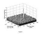
- the resultis a single array, a collection of which comprises a three-dimensional figure, such as that depicted in Figure 4 .
- a frequency domain correlation operationmay require a multi-step process.
- the resultsare stored in the frame buffer memory 60, they are copied back into the texture memory unit 50, and the programmable graphics processor 20 is re-initiated. The process is iteratively performed until the frequency domain correlation operation is completed.
- the frequency domain correlation operationoperates between a signal received from one or more GNSS satellites and a locally generated replica signal of a particular satellite. If there is a correlation between the two arrays as a result of the frequency domain correlation operation, then there is a maximal value as shown in Figure 4 .
- one of the axesis the Doppler shift value and the other is a time phase shift value. If a maximal value is found, then the Doppler shift and the time shift corresponding to the maximal value are then used to lock onto that satellite.
- the Doppler value and the time shift valuemay be used by a phase or delay lock loop to lock onto the satellite, as is well known to those skilled in the art.
- One method to track a satelliteis to generate time shifted correlator samples, one on either side of the time shift value of the code phase estimate used for tracking the satellite, and typically equally spaced from the code phase estimate.
- the time shifted correlator samplesare then compared to one another and the time shift value is adjusted based upon the comparing step, such that the time shifted correlator samples remain equal to one another.
- a programmable graphics processor 20to perform operations such as FFT transforms or inverse transforms on a single array of data or a frequency domain correlation on two arrays of data is advantageous because such programmable processors 20 are adapted to perform calculations in parallel, rapidly, thereby saving time.
- many GPS receivers 10are part of an apparatus containing processors that perform other functions, such as cellular phone, PDA, digital camera, etc. This apparatus may have a programmable graphics processor 20 that is otherwise idling while the GPS receiver 10 is performing the functions of acquiring and tracking signals from various GPS satellites.
- the present inventionmore efficiently utilizes all of the resources of a portable electronic device in acquiring and tracking a GPS signal.
Landscapes
- Engineering & Computer Science (AREA)
- Signal Processing (AREA)
- Radar, Positioning & Navigation (AREA)
- Remote Sensing (AREA)
- Physics & Mathematics (AREA)
- General Physics & Mathematics (AREA)
- Computer Networks & Wireless Communication (AREA)
- Computer Graphics (AREA)
- Theoretical Computer Science (AREA)
- Position Fixing By Use Of Radio Waves (AREA)
Description
- The present invention relates to a method for processing signals from a global navigation satellite system ("GNSS"), such as the Global Positioning System (GPS), the Galileo System, or the GLONASS system, and more particularly to a method for processing such signals by the use of a conventional graphics processor. The present invention also relates to an article of manufacture comprising computer readable program code configured to process the signals from such a satellite navigation system.
- GNSS is well known in the art. Presently, GPS is fully operational and GLONASS is functional but in some disarray; the Galileo System is beginning to be deployed. The present invention can be used with all types of GNSS, although for the purpose of explanation of the present invention, reference will be made to GPS.
Figure 1 shows a schematic diagram of GPS to which the method of the present invention can be applied. The space segment of GPS consists of a plurality of satellites (24), with another set of operational spare satellites (such as 6), for a total of thirty (30) satellites in orbit. Each satellite orbits the earth at an approximate altitude of 20,160 km and repeats its ground track over any particular point on earth approximately twice per sidereal day (23 hours, 56 minutes, 4 seconds). The satellites are arranged in 6 orbital planes inclined at approximately 55 degrees with respect to the equator and are evenly spaced around the equator.- For GPS applications, at any location on earth, the signals from four (4) different satellites can uniquely determine the position/time at the received location. The system is designed so that all satellites nominally transmit at the same time and on the same carrier frequency (1575.42 MHz). Multiple access, which is the ability to receive an individual satellite's signal in the presence of other signals on the same frequency, is accomplished by means of a unique repeating modulation, or "spreading code," assigned to each satellite. This modulation enables the receiver to selectively decode the navigation data from a particular satellite, and serves as a unique identifier. Because each satellite is orbiting the earth and is moving relative to the receiver's location, the signal received from that satellite at that location and time will have a specific Doppler shift frequency with respect to the nominal carrier frequency. From the knowledge of the Doppler shift and the timing of the modulation code repetitions, or "code phase," for each received satellite signal, the position/time at the particular location on earth can be determined using the principle of triangulation.
- The mathematics of processing the signal(s) from the GNSS satellites is well known in the art. In general, the signal from each satellite must first be acquired, and once acquired, it must be tracked. For acquisition, the frequency spectrum is searched over many Doppler values, which are applied to locally stored replicas of the expected satellite signal. Thus, for example, a number of replicas are generated with frequency shifts of up to +/- 5 KHz from the expected frequency for each satellite. Each replica is characterized by its associated frequency shift. A frequency domain correlation operation is then performed between the received signal and an array of replica signals having the various Doppler shifted values. From this frequency domain correlation operation, a maximal value is determined and compared against a threshold. The location of a unique maximum that exceeds the threshold identifies both the Doppler frequency and the timing of the code modulation for a particular satellite signal. From this calculation, the information relative to Doppler shift and time delay is used to track the satellite so identified. Typically, this is used to adjust the tracking loops in the receiver, e.g. a phase lock loop and a delay lock loop. While in principle this calculation appears to be simple, the actual implementation is quite computationally intensive. Considerations for a practical GPS receiver must include not only cost, but also rapidity of the calculation, and in most cases power (usually battery) consumption, since these receivers are often intended to be used in portable devices.
- One prior art processor is called a programmable graphics processor, such as those available from Nvidia Corporation of Santa Clara, California. A programmable graphics processor, as will be discussed in greater detail hereinafter, is characterized by a rasterizer unit, a texture unit, a pixel shader unit, and a frame buffer unit. The texture unit and the frame buffer unit are simply memory locations where data are stored. The rasterizer unit receives data indicating values of endpoints of an array in the texture unit and performs an interpolation between the endpoint values, and sends the result to the pixel shader unit. The pixel shader unit operates on the data read from the texture unit and stores the result in the frame buffer unit for ultimate display on a display unit such as an LCD display. The pixel shader unit is the programmable portion of the programmable graphics processor.
- It is one aim of the present invention to provide a method of rapidly processing signals from a GNSS using the elements of a graphics processor.
- In the present invention, a method of processing a signal from a navigation satellite first receives the signal from the navigation satellite and forms a received signal. The received signal is converted into a digitized form signal. The digitized form signal is transformed by a programmable graphics processor having a rasterizer unit, a pixel shader unit and a memory unit. A first array of a first corresponding data of the digitized form signal are stored in the memory unit. The first addresses and values of endpoints of the first array of the first corresponding data of the digitized form signal are supplied to the rasterizer unit. The rasterizer unit generates a plurality of interpolated values between values of endpoints of the first array. The plurality of interpolated values and values of endpoints for the first array correspond to addresses in the memory unit for the first array of first corresponding data of the digitized form signal. The pixel shader unit operates on the first array of first corresponding data of the digitized signal from the memory unit, based upon the plurality of interpolated values and values of the endpoints for the first array supplied from the rasterizer unit to form a resulting array of corresponding data. The resulting array is stored in the memory unit, at the first addresses.
Figure 1 is a schematic diagram of GPS.Figure 2 is a schematic block diagram of an apparatus suitable for carrying out the method of the present invention, and for executing the computer readable program code of the present invention.Figure 3 is a detailed block level diagram of a portion of a programmable graphics processor for carrying out the method of the present invention.Figure 4 is a chart showing the determination of the particular Doppler value and time shift used to acquire and track a GNSS satellite.Figure 2 shows a block level schematic diagram of anapparatus 10 suitable for carrying out the method of the present invention. Theapparatus 10 is a receiver for receiving signals generated from one or more GNSS satellites. As previously discussed, for the purpose of explanation of the present invention, the discussion set forth herein is focused on GPS, although the present invention may be used in the processing of a signal from any GNSS satellite.- The
apparatus 10 comprises an antenna for receiving a signal from a GPS satellite. The signal, Shf, (Signal High Frequency) is received by theapparatus 10 and is processed through a conventionalanalog processing circuit 12, which includes circuits such as a low noise amplifier (LNA) and a frequency down converter circuit, to generate an analog processed signal, Sif (Signal Intermediate Frequency). The signal Sif is supplied to asecond processing circuit 14 which may include further down conversion of the frequency Sif, and is then digitized to form a digitized form signal d(k) of the received signal Shf. Finally, the digitized form signal d(k) is supplied to adigital processing circuit 16, which may include one or more digital processors, such as DSP, microprocessor, state machine, and/or hardwired logic circuits. In the context of the present invention, thedigital processing circuit 16 also includes aprogrammable graphics processor 20. Since all of the GNSS satellites operate at the same frequency, theapparatus 10 receives signals from all of the satellites (that are in view of theGPS receiver apparatus 10, or are received by the apparatus 10) and processes them in parallel. Figure 3 shows a block level diagram of aprogrammable graphics processor 20 useful for carrying out the method of the present invention. Theprogrammable graphics processor 20 is a conventional well known programmable graphics processor, such as that from Nvidia Corporation of Santa Clara, California. Theprogrammable graphics processor 20 typically in the prior art has been used to take data and render the data for display on a display device, such as an LCD display, or to perform other image processing tasks for later display, such as medical diagnostic imaging. Thus, although they are processors, in the sense that they are capable of performing logic comparison of data, and manipulation thereof, programmable graphics processors of this type have typically been used for the special purpose of creating realistic displays on a display device.- The
programmable graphics processor 20 shown inFigure 3 is useful for carrying out the method of the present invention, and comprises arasterizer unit 30, apixel shader unit 40, one ormore texture units 50, and aframe buffer unit 60. Thetexture units 50 and theframe buffer unit 60 are logically separate memory units, but physically they may comprise a single memory unit. In the prior art, therasterizer unit 30 when supplied with values at endpoints of an array can perform an interpolation of the values in between the values of the endpoints of the array. Further, in the prior art, thepixel shader unit 40 is the programmable portion of theprogrammable graphics processor 20. Thepixel shader unit 40 can read data from thetexture units 50 and output the resultant data into theframe buffer unit 60. From the frame -buffer unit 60, the data is typically displayed on a display device (not shown). - In the method of the present invention, the
programmable graphics processor 20 receives values of endpoints of an array. Thus, as shown inFigure 3 , the values of the endpoint of an array received by theprocessor 20 may have the values (A1, A2, A3 and A4). Each value A1, A2, A3 or A4 may contain a set of values. Associated with each value which are the endpoints of the array are addresses. Thus, although not shown inFigure 3 , an address of (x1, y1) would be associated with the value A1, an, address of (x2, y2) would be associate with the value A2, an address of (x3, y3) would be associate with the value A3, and an address of (x4, y4) would be associate with the value A4. - The
rasterizer unit 30 receives the inputted information (x1, y1), A1; (x2, y2), A2; (x3, y3), A3; and (x4, y4), A4, and operates on them by performing an interpolation of all the values between all of the endpoints A1, A2, A3 and A4. In essence, therasterizer unit 30 performs an interpolation of all the values in the array bounded by the endpoint values of A1, A2, A3 and A4. The endpoint values A1, A2, A3, and A4, along with the interpolated values therebetween, are passed to thepixel shader unit 40. Thepixel shader unit 40 reads the array of data from thetexture memory unit 50 at the addresses defined by A1, A2, A3, A4 and all the values interpolated therebetween. An array of data is previously stored in thetexture memory unit 50 at the location of A1, A2, A3 and A4. - The
pixel shader unit 40 operates on the array of data from thetexture memory unit 50 at the address location of A1, A2, A3 and A4, and then stores the result in the framebuffer memory unit 60 at the address location defined by (x1, y1); (x2, y2); (x3, y3); and (x4, y4). - In a preferred embodiment, because the
programmable graphics processor 20 is particularly adapted to process data in the form of a triangle, the array of data whose endpoint values are defined by A1, A2, A3 and A4, are the endpoints of two triangles adjacent to one another. - One of the processes that the
programmable graphics processor 20 can perform is a Fast Fourier Transform (FFT) or an inverse FFT of an array. An FFT operation or an inverse FFT operation is one of the operations commonly used in the processing of a signal from a GNSS satellite to determine the position/time of a location by a receiver. Thus, for example, in an FFT operation, the untransformed array of data is stored in thetexture memory unit 50 at the address locations defined by the values of endpoints A1, A2, A3, A4, and the values therebetween interpolated by therasterizer unit 30. Thepixel shader unit 40 operates on the array of data read from thetexture memory unit 50 to form an FFT transform thereof and store the results at the addresses (x1, y1); (x2, y2); (x3, y3); and (x4, y4) in the framebuffer memory unit 60. Typically, in an FFT (or inverse FFT) operation, as is well known in the art, many process steps are required. Thus, after the results are stored in the framebuffer memory unit 60, the results are then copied to thetexture memory unit 50 at the address location defined by the endpoint values of the array A1, A2, A3, and A4. Theprogrammable graphics processor 20 is then re-initiated. This iterative process continues until the FFT (or inverse FFT) operation is completed. The programming of thepixel shader unit 40 to perform the FFT operation (or an inverse FFT operation) is well known to those in the art. - Another process that the
programmable graphics processor 20 can perform is a frequency domain correlation operation between two arrays of data: one array is the array of data received from the GNSS satellites, while another array of data is one of the local replicas having Doppler shifted values. The operation of frequency domain correlation operation between two arrays of data by theprogrammable graphics processor 20 includes forming an FFT (or an inverse FFT) operation on an array of data. The two arrays of data, (defined by the values of the endpoints A1, A2, A3, and A4, and by the endpoints B1, B2, B3, and B4) are stored in thetexture memory unit 50 at locations defined by the values of endpoints A1, A2, A3, A4, and the values therebetween interpolated by therasterizer unit 30, and by the values of endpoints B1, B2, B3, B4, and the values therebetween interpolated by therasterizer unit 30. The two arrays of data are read from thetexture memory unit 50 by thepixel shader unit 40, and operated thereon to form a frequency domain correlation thereof. The result is a single array, a collection of which comprises a three-dimensional figure, such as that depicted inFigure 4 . This result is stored in theframe buffer memory 60. Again, similar to the discussion heretofore, with regard to the FFT (or inverse FFT) operation, a frequency domain correlation operation may require a multi-step process. Thus, after the results are stored in theframe buffer memory 60, they are copied back into thetexture memory unit 50, and theprogrammable graphics processor 20 is re-initiated. The process is iteratively performed until the frequency domain correlation operation is completed. - The frequency domain correlation operation operates between a signal received from one or more GNSS satellites and a locally generated replica signal of a particular satellite. If there is a correlation between the two arrays as a result of the frequency domain correlation operation, then there is a maximal value as shown in
Figure 4 . In the graph shown inFigure 4 , one of the axes is the Doppler shift value and the other is a time phase shift value. If a maximal value is found, then the Doppler shift and the time shift corresponding to the maximal value are then used to lock onto that satellite. Thus, for example, the Doppler value and the time shift value may be used by a phase or delay lock loop to lock onto the satellite, as is well known to those skilled in the art. - Once the signal from a satellite is acquired, the satellite must be tracked as it traverses its orbit. One method to track a satellite is to generate time shifted correlator samples, one on either side of the time shift value of the code phase estimate used for tracking the satellite, and typically equally spaced from the code phase estimate. The time shifted correlator samples are then compared to one another and the time shift value is adjusted based upon the comparing step, such that the time shifted correlator samples remain equal to one another.
- The use of a
programmable graphics processor 20 to perform operations such as FFT transforms or inverse transforms on a single array of data or a frequency domain correlation on two arrays of data is advantageous because suchprogrammable processors 20 are adapted to perform calculations in parallel, rapidly, thereby saving time. In addition,many GPS receivers 10 are part of an apparatus containing processors that perform other functions, such as cellular phone, PDA, digital camera, etc. This apparatus may have aprogrammable graphics processor 20 that is otherwise idling while theGPS receiver 10 is performing the functions of acquiring and tracking signals from various GPS satellites. Thus, the present invention more efficiently utilizes all of the resources of a portable electronic device in acquiring and tracking a GPS signal.
Claims (16)
- A method of processing a signal from a navigation satellite comprising:receiving a signal from said navigation satellite to form a received signal;conversing said received signal into a digitized form signal;transforming said digitized form signal by a programmable graphics processor having a rasterizer unit, a pixel shader unit and a memory unit, wherein a first array of a first data of said digitized form signal are stored in said memory unit, and wherein said transforming step further comprises:supplying first addresses and values of endpoints of said first array of said first data of said digitized form signal to said rasterizer unit, said endpoints corresponding to the endpoints of a triangle;generating a plurality of interpolated values between values of endpoints of said first array, by said rasterizer unit;operating on said first array of first data of said digitized signal from the memory unit by said pixel shader unit based upon said plurality of interpolated values and values of said endpoints for said first array supplied from said rasterizer unit to form a resulting array of data; andstoring said resulting array in said memory unit, at said first addresses.
- The method of claim 1 wherein a second array of a second data of said digitized form signal are stored in said memory unit, and wherein said transforming step further comprising:supplying second addresses and values of endpoints of said second array of said second data of said digitized form signal to said rasterizer unit;generating a plurality of interpolated values between values of endpoints of said second array, by said rasterizer unit, wherein said plurality of interpolated values and values of endpoints for said second array corresponds to addresses in said memory unit for said second array of second data of said digitized form signal;operating on said first array and second array of first and second data of said digitized signal from the memory unit by said pixel shader unit based upon said plurality of interpolated values and values of said endpoints for said first and second array supplied from said rasterizer unit to form a resulting array of data; andstoring said resulting array in said memory unit, at said second addresses.
- The method of claim 2 wherein said second addresses are the same as the first addresses.
- The method of claim 3 wherein said first data of said digitized form signal corresponds to said received signal and has a characteristic Doppler shift with respect to a nominal frequency.
- The method of claim 4 wherein said second data of said digitized form signal is a pre-computed replica signal of said digitized form signal.
- The method of claim 5 wherein said processing is performed for a plurality of navigation satellites to receive a plurality of signals from said plurality of satellites, determining the position/time related data based upon said plurality of signals received.
- The method of claim 6 wherein said pre-computed replica signal has a characteristic Doppler frequency, and a plurality of samples.
- The method of claim 7 wherein said method acquires a plurality of signals from a plurality of navigation satellites and
wherein said second array of second data for said digitized form signal comprises a plurality of frequency shifted signals, each frequency shifted signal shifted in frequency by a characteristic Doppler value. - The method of acquiring a plurality of signals from a plurality of navigation satellite of claim 8 wherein said method comprises:performing a frequency domain correlation operation between said first array of digitized form signals and said second array of digitized form signals to form an array of correlation functions.
- The method of acquiring a plurality of signals from a plurality of navigation satellite of claim 9, further comprising:determining a maximal value, if one exists, for each received signal.
- The method of acquiring a plurality of signals from a plurality of navigation satellites of claim 10 wherein in the event a maximal value is determined, the associated characteristic Doppler shift and associated code phase value of the frequency shifted signal of the first array corresponding to the maximal value in the array of correlation functions is used to lock onto the received signal.
- The method of claim 10 wherein said processing a signal from a navigation satellite comprises a method of tracking each of said plurality of satellites.
- The method of claim 11 wherein said method of tracking further comprising:generating a plurality of time shifted correlator samples, time shifted on either side of said code phase value, associated with said maximal value, at said frequency shift associated with said maximal value;comparing said plurality of time shifted correlator samples;adjusting said time shift based on said comparing step.
- An article of manufacture for processing a signal from a navigation satellite, wherein the signal is received and is converted into a digitized form signal, and is further transformed by a programmable graphics processor having a rasterizer unit, a pixel shader unit and a memory unit, wherein a first array of a first data of said digitized form signal are stored in said memory unit, wherein said article of manufacturing comprising:computer usable medium having computer readable program code embedded therein, wherein said computer usable medium further comprises:computer readable program code configured to cause the programmable graphics processor to received first addresses and values of endpoints of the first array of first data of said digitized form signal to said rasterizer unit, said endpoints corresponding to the endpoints of a triangle;computer readable program code configured to cause the programmable graphics processor to generate a plurality of interpolated values between values of said endpoints of said first array by said rasterizer unit;computer readable program code configured to cause the programmable graphics processor to operate on said first array of first data of said digitized form signal from the memory unit by said pixel shader unit based upon said plurality of interpolated values and values of said endpoints for said first array supplied from said rasterizer unit, to form a resulting array of data; andcomputer readable program code configured to cause the programmable graphics processor to store the resulting array in said memory unit at said first addresses.
- The article of manufacture of claim 14 wherein a second array of a second data of said digitized form signal are stored in said memory unit, and wherein said computer usable medium further comprises:computer readable program code configured to cause the programmable graphics processor to received second addresses and values of endpoints of the second array of second data of said digitized form signal to said rasterizer unit;computer readable program code configured to cause the programmable graphics processor to generate a plurality of interpolated values between values of said endpoints of said second array by said rasterizer unit, wherein said plurality of interpolated values and values of said endpoints for said second array corresponds to addresses in said memory unit for said second array of second data of said digitized form signal;computer readable program code configured to cause the programmable graphics processor to operate on said second array of first data of said digitized form signal from the memory unit by said pixel shader unit based upon said plurality of interpolated values and values of said endpoints for said second array supplied from said rasterizer unit, to form a resulting array of data;computer readable program code configured to cause the programmable graphics processor to store the resulting array in said memory unit at said second addresses;wherein said first data of said digitized form signal corresponds to said received signal and has a characteristic Doppler shift with respect to a nominal frequency;wherein said second data of said digitized form signal is a pre-computed replica signal of said digitized form signal, having a characteristic Doppler frequency and a plurality of samples; andwherein said processing is performed for a plurality of navigation satellites to receive a plurality of signals from said plurality of navigation satellites to determine the position/time relates data based upon the plurality of signals received.
- The article of manufacture of claim 14 and including computer readable program code configured to carry out the method of any of claims 2 to 13.
Applications Claiming Priority (1)
| Application Number | Priority Date | Filing Date | Title |
|---|---|---|---|
| PCT/US2006/034924WO2008030241A1 (en) | 2006-09-08 | 2006-09-08 | Processing of signals from global navigation satellite systems by a graphics processor |
Publications (3)
| Publication Number | Publication Date |
|---|---|
| EP2059908A1 EP2059908A1 (en) | 2009-05-20 |
| EP2059908A4 EP2059908A4 (en) | 2011-11-16 |
| EP2059908B1true EP2059908B1 (en) | 2014-11-12 |
Family
ID=39157540
Family Applications (1)
| Application Number | Title | Priority Date | Filing Date |
|---|---|---|---|
| EP06803142.6ANot-in-forceEP2059908B1 (en) | 2006-09-08 | 2006-09-08 | Processing of signals from global navigation satellite systems by a graphics processor |
Country Status (4)
| Country | Link |
|---|---|
| US (1) | US20100013830A1 (en) |
| EP (1) | EP2059908B1 (en) |
| JP (1) | JP2010501853A (en) |
| WO (1) | WO2008030241A1 (en) |
Family Cites Families (18)
| Publication number | Priority date | Publication date | Assignee | Title |
|---|---|---|---|---|
| US5113178A (en)* | 1988-01-29 | 1992-05-12 | Aisin Seiki K.K. | Position display apparatus |
| JP3147541B2 (en)* | 1992-11-06 | 2001-03-19 | 株式会社豊田中央研究所 | Obstacle recognition device for vehicles |
| US5903597A (en)* | 1996-05-20 | 1999-05-11 | Trimble Navigation Limited | Suppression on multipath signal effects |
| US6493378B1 (en)* | 1998-01-06 | 2002-12-10 | Topcon Gps Llc | Methods and apparatuses for reducing multipath errors in the demodulation of pseudo-random coded signals |
| US6453237B1 (en)* | 1999-04-23 | 2002-09-17 | Global Locate, Inc. | Method and apparatus for locating and providing services to mobile devices |
| US6829534B2 (en)* | 1999-04-23 | 2004-12-07 | Global Locate, Inc. | Method and apparatus for performing timing synchronization |
| FI19992653A7 (en)* | 1999-12-09 | 2001-06-10 | Nokia Mobile Phones Ltd | Method for synchronizing a receiver and a receiver |
| US6628231B2 (en)* | 2000-02-17 | 2003-09-30 | Lockheed Martin Corp. | Location of radio frequency emitting targets |
| WO2001063561A1 (en)* | 2000-02-25 | 2001-08-30 | The Research Foundation Of State University Of New York | Apparatus and method for volume processing and rendering |
| US6931055B1 (en)* | 2000-04-18 | 2005-08-16 | Sirf Technology, Inc. | Signal detector employing a doppler phase correction system |
| JP3864807B2 (en)* | 2002-02-28 | 2007-01-10 | ソニー株式会社 | Correlation detection apparatus, correlation detection method, and reception apparatus |
| US7075530B2 (en)* | 2003-02-27 | 2006-07-11 | International Business Machines Corporation | Fast lighting processors |
| GB0319697D0 (en)* | 2003-08-21 | 2003-09-24 | Falanx Microsystems As | Method of and apparatus for differential encoding and decoding |
| US7139005B2 (en)* | 2003-09-13 | 2006-11-21 | Microsoft Corporation | Optimized fixed-point mathematical library and graphics functions for a software-implemented graphics rendering system and method using a normalized homogenous coordinate system |
| US20050128937A1 (en)* | 2003-12-11 | 2005-06-16 | Nokia Corporation | Determination of correlation in the frequency domain |
| GB0425204D0 (en)* | 2004-11-15 | 2004-12-15 | Falanx Microsystems As | Processing of 3-dimensional graphics |
| US7630427B2 (en)* | 2005-09-29 | 2009-12-08 | Qualcomm Incorporated | Systems, methods, and apparatus for establishing finger lock state |
| US8170085B2 (en)* | 2006-03-09 | 2012-05-01 | CSR Technology Holdings Inc. | Multipath error estimation in satellite navigation receivers |
- 2006
- 2006-09-08EPEP06803142.6Apatent/EP2059908B1/ennot_activeNot-in-force
- 2006-09-08WOPCT/US2006/034924patent/WO2008030241A1/enactiveApplication Filing
- 2006-09-08USUS12/376,115patent/US20100013830A1/ennot_activeAbandoned
- 2006-09-08JPJP2009525533Apatent/JP2010501853A/enactivePending
Also Published As
| Publication number | Publication date |
|---|---|
| EP2059908A1 (en) | 2009-05-20 |
| WO2008030241A1 (en) | 2008-03-13 |
| EP2059908A4 (en) | 2011-11-16 |
| JP2010501853A (en) | 2010-01-21 |
| US20100013830A1 (en) | 2010-01-21 |
Similar Documents
| Publication | Publication Date | Title |
|---|---|---|
| JP4435720B2 (en) | GPS receiver and method of processing GPS signals | |
| JP4674707B2 (en) | Spread spectrum receiver architecture and method | |
| US8170086B2 (en) | Method and apparatus for performing signal correlation | |
| US7184464B2 (en) | Apparatus for computing signal correlation at multiple resolutions | |
| US7471717B2 (en) | Apparatus and method for acquiring spread-spectrum signals | |
| EP2093584A1 (en) | Processing received satellite radio signals | |
| JP2007505292A (en) | Controls and functions for satellite positioning system receivers. | |
| JP2017173332A (en) | GNSS signal processor | |
| JP2005535880A (en) | Method and apparatus for performing signal correlation at multiple resolutions to mitigate multipath interference | |
| TW544527B (en) | Radiofrequency signal receiver with means for correcting the effects of multipath signals, and method for activating the receiver | |
| JP2004519676A (en) | Method and apparatus for processing a GPS signal with a matched filter | |
| CN102928854A (en) | GPS capture unit design method based on matched filter | |
| JP2008076395A (en) | Memory reduction apparatus for gnss receiver and its method | |
| US7750846B2 (en) | Receiver for radio positioning signals | |
| EP2059908B1 (en) | Processing of signals from global navigation satellite systems by a graphics processor | |
| US9547087B1 (en) | Sync feedback for time to first fix | |
| JP4499717B2 (en) | GPS receiver with short acquisition time | |
| Akopian et al. | Fast and parallel matched filters in time domain | |
| JP5455542B2 (en) | GPS receiver and method of processing GPS signals | |
| JP2002162247A (en) | Gps system | |
| JP2002131410A (en) | GPS receiver |
Legal Events
| Date | Code | Title | Description |
|---|---|---|---|
| PUAI | Public reference made under article 153(3) epc to a published international application that has entered the european phase | Free format text:ORIGINAL CODE: 0009012 | |
| 17P | Request for examination filed | Effective date:20090218 | |
| AK | Designated contracting states | Kind code of ref document:A1 Designated state(s):AT BE BG CH CY CZ DE DK EE ES FI FR GB GR HU IE IS IT LI LT LU LV MC NL PL PT RO SE SI SK TR | |
| AX | Request for extension of the european patent | Extension state:AL BA HR MK RS | |
| RIC1 | Information provided on ipc code assigned before grant | Ipc:G01S 19/37 20100101ALI20110929BHEP Ipc:G06T 15/00 20110101AFI20110929BHEP | |
| A4 | Supplementary search report drawn up and despatched | Effective date:20111017 | |
| RIC1 | Information provided on ipc code assigned before grant | Ipc:G01S 19/37 20100101ALI20111008BHEP Ipc:G06T 15/00 20110101AFI20111008BHEP | |
| RIC1 | Information provided on ipc code assigned before grant | Ipc:G06T 15/00 20110101AFI20111103BHEP Ipc:G01S 19/37 20100101ALI20111103BHEP | |
| DAX | Request for extension of the european patent (deleted) | ||
| GRAP | Despatch of communication of intention to grant a patent | Free format text:ORIGINAL CODE: EPIDOSNIGR1 | |
| INTG | Intention to grant announced | Effective date:20140519 | |
| GRAS | Grant fee paid | Free format text:ORIGINAL CODE: EPIDOSNIGR3 | |
| GRAA | (expected) grant | Free format text:ORIGINAL CODE: 0009210 | |
| RAP1 | Party data changed (applicant data changed or rights of an application transferred) | Owner name:CAMBRIDGE SILICON RADIO LIMITED | |
| AK | Designated contracting states | Kind code of ref document:B1 Designated state(s):AT BE BG CH CY CZ DE DK EE ES FI FR GB GR HU IE IS IT LI LT LU LV MC NL PL PT RO SE SI SK TR | |
| REG | Reference to a national code | Ref country code:GB Ref legal event code:FG4D | |
| REG | Reference to a national code | Ref country code:CH Ref legal event code:EP | |
| REG | Reference to a national code | Ref country code:AT Ref legal event code:REF Ref document number:696150 Country of ref document:AT Kind code of ref document:T Effective date:20141115 | |
| REG | Reference to a national code | Ref country code:IE Ref legal event code:FG4D | |
| REG | Reference to a national code | Ref country code:DE Ref legal event code:R096 Ref document number:602006043661 Country of ref document:DE Effective date:20141224 | |
| REG | Reference to a national code | Ref country code:NL Ref legal event code:VDEP Effective date:20141112 | |
| REG | Reference to a national code | Ref country code:AT Ref legal event code:MK05 Ref document number:696150 Country of ref document:AT Kind code of ref document:T Effective date:20141112 | |
| PG25 | Lapsed in a contracting state [announced via postgrant information from national office to epo] | Ref country code:PT Free format text:LAPSE BECAUSE OF FAILURE TO SUBMIT A TRANSLATION OF THE DESCRIPTION OR TO PAY THE FEE WITHIN THE PRESCRIBED TIME-LIMIT Effective date:20150312 Ref country code:ES Free format text:LAPSE BECAUSE OF FAILURE TO SUBMIT A TRANSLATION OF THE DESCRIPTION OR TO PAY THE FEE WITHIN THE PRESCRIBED TIME-LIMIT Effective date:20141112 Ref country code:IS Free format text:LAPSE BECAUSE OF FAILURE TO SUBMIT A TRANSLATION OF THE DESCRIPTION OR TO PAY THE FEE WITHIN THE PRESCRIBED TIME-LIMIT Effective date:20150312 Ref country code:NL Free format text:LAPSE BECAUSE OF FAILURE TO SUBMIT A TRANSLATION OF THE DESCRIPTION OR TO PAY THE FEE WITHIN THE PRESCRIBED TIME-LIMIT Effective date:20141112 Ref country code:LT Free format text:LAPSE BECAUSE OF FAILURE TO SUBMIT A TRANSLATION OF THE DESCRIPTION OR TO PAY THE FEE WITHIN THE PRESCRIBED TIME-LIMIT Effective date:20141112 Ref country code:FI Free format text:LAPSE BECAUSE OF FAILURE TO SUBMIT A TRANSLATION OF THE DESCRIPTION OR TO PAY THE FEE WITHIN THE PRESCRIBED TIME-LIMIT Effective date:20141112 | |
| PG25 | Lapsed in a contracting state [announced via postgrant information from national office to epo] | Ref country code:GR Free format text:LAPSE BECAUSE OF FAILURE TO SUBMIT A TRANSLATION OF THE DESCRIPTION OR TO PAY THE FEE WITHIN THE PRESCRIBED TIME-LIMIT Effective date:20150213 Ref country code:PL Free format text:LAPSE BECAUSE OF FAILURE TO SUBMIT A TRANSLATION OF THE DESCRIPTION OR TO PAY THE FEE WITHIN THE PRESCRIBED TIME-LIMIT Effective date:20141112 Ref country code:LV Free format text:LAPSE BECAUSE OF FAILURE TO SUBMIT A TRANSLATION OF THE DESCRIPTION OR TO PAY THE FEE WITHIN THE PRESCRIBED TIME-LIMIT Effective date:20141112 Ref country code:CY Free format text:LAPSE BECAUSE OF FAILURE TO SUBMIT A TRANSLATION OF THE DESCRIPTION OR TO PAY THE FEE WITHIN THE PRESCRIBED TIME-LIMIT Effective date:20141112 Ref country code:SE Free format text:LAPSE BECAUSE OF FAILURE TO SUBMIT A TRANSLATION OF THE DESCRIPTION OR TO PAY THE FEE WITHIN THE PRESCRIBED TIME-LIMIT Effective date:20141112 Ref country code:AT Free format text:LAPSE BECAUSE OF FAILURE TO SUBMIT A TRANSLATION OF THE DESCRIPTION OR TO PAY THE FEE WITHIN THE PRESCRIBED TIME-LIMIT Effective date:20141112 | |
| PG25 | Lapsed in a contracting state [announced via postgrant information from national office to epo] | Ref country code:EE Free format text:LAPSE BECAUSE OF FAILURE TO SUBMIT A TRANSLATION OF THE DESCRIPTION OR TO PAY THE FEE WITHIN THE PRESCRIBED TIME-LIMIT Effective date:20141112 Ref country code:CZ Free format text:LAPSE BECAUSE OF FAILURE TO SUBMIT A TRANSLATION OF THE DESCRIPTION OR TO PAY THE FEE WITHIN THE PRESCRIBED TIME-LIMIT Effective date:20141112 Ref country code:RO Free format text:LAPSE BECAUSE OF FAILURE TO SUBMIT A TRANSLATION OF THE DESCRIPTION OR TO PAY THE FEE WITHIN THE PRESCRIBED TIME-LIMIT Effective date:20141112 Ref country code:SK Free format text:LAPSE BECAUSE OF FAILURE TO SUBMIT A TRANSLATION OF THE DESCRIPTION OR TO PAY THE FEE WITHIN THE PRESCRIBED TIME-LIMIT Effective date:20141112 Ref country code:DK Free format text:LAPSE BECAUSE OF FAILURE TO SUBMIT A TRANSLATION OF THE DESCRIPTION OR TO PAY THE FEE WITHIN THE PRESCRIBED TIME-LIMIT Effective date:20141112 | |
| REG | Reference to a national code | Ref country code:DE Ref legal event code:R097 Ref document number:602006043661 Country of ref document:DE | |
| PLBE | No opposition filed within time limit | Free format text:ORIGINAL CODE: 0009261 | |
| STAA | Information on the status of an ep patent application or granted ep patent | Free format text:STATUS: NO OPPOSITION FILED WITHIN TIME LIMIT | |
| 26N | No opposition filed | Effective date:20150813 | |
| PG25 | Lapsed in a contracting state [announced via postgrant information from national office to epo] | Ref country code:IT Free format text:LAPSE BECAUSE OF FAILURE TO SUBMIT A TRANSLATION OF THE DESCRIPTION OR TO PAY THE FEE WITHIN THE PRESCRIBED TIME-LIMIT Effective date:20141112 | |
| PG25 | Lapsed in a contracting state [announced via postgrant information from national office to epo] | Ref country code:SI Free format text:LAPSE BECAUSE OF FAILURE TO SUBMIT A TRANSLATION OF THE DESCRIPTION OR TO PAY THE FEE WITHIN THE PRESCRIBED TIME-LIMIT Effective date:20141112 | |
| PG25 | Lapsed in a contracting state [announced via postgrant information from national office to epo] | Ref country code:MC Free format text:LAPSE BECAUSE OF FAILURE TO SUBMIT A TRANSLATION OF THE DESCRIPTION OR TO PAY THE FEE WITHIN THE PRESCRIBED TIME-LIMIT Effective date:20141112 Ref country code:LU Free format text:LAPSE BECAUSE OF FAILURE TO SUBMIT A TRANSLATION OF THE DESCRIPTION OR TO PAY THE FEE WITHIN THE PRESCRIBED TIME-LIMIT Effective date:20150908 | |
| REG | Reference to a national code | Ref country code:CH Ref legal event code:PL | |
| REG | Reference to a national code | Ref country code:IE Ref legal event code:MM4A | |
| REG | Reference to a national code | Ref country code:FR Ref legal event code:ST Effective date:20160531 | |
| PG25 | Lapsed in a contracting state [announced via postgrant information from national office to epo] | Ref country code:IE Free format text:LAPSE BECAUSE OF NON-PAYMENT OF DUE FEES Effective date:20150908 Ref country code:CH Free format text:LAPSE BECAUSE OF NON-PAYMENT OF DUE FEES Effective date:20150930 Ref country code:LI Free format text:LAPSE BECAUSE OF NON-PAYMENT OF DUE FEES Effective date:20150930 | |
| PG25 | Lapsed in a contracting state [announced via postgrant information from national office to epo] | Ref country code:FR Free format text:LAPSE BECAUSE OF NON-PAYMENT OF DUE FEES Effective date:20150930 | |
| REG | Reference to a national code | Ref country code:DE Ref legal event code:R082 Ref document number:602006043661 Country of ref document:DE Representative=s name:WINTER, BRANDL - PARTNERSCHAFT MBB, PATENTANWA, DE Ref country code:DE Ref legal event code:R081 Ref document number:602006043661 Country of ref document:DE Owner name:QUALCOMM TECHNOLOGIES INTERNATIONAL, LTD., GB Free format text:FORMER OWNER: CAMBRIDGE SILICON RADIO LTD., CAMBRIDGE, CAMBRIDGESHIRE, GB Ref country code:DE Ref legal event code:R082 Ref document number:602006043661 Country of ref document:DE Representative=s name:WINTER, BRANDL, FUERNISS, HUEBNER, ROESS, KAIS, DE | |
| PG25 | Lapsed in a contracting state [announced via postgrant information from national office to epo] | Ref country code:BG Free format text:LAPSE BECAUSE OF FAILURE TO SUBMIT A TRANSLATION OF THE DESCRIPTION OR TO PAY THE FEE WITHIN THE PRESCRIBED TIME-LIMIT Effective date:20141112 Ref country code:HU Free format text:LAPSE BECAUSE OF FAILURE TO SUBMIT A TRANSLATION OF THE DESCRIPTION OR TO PAY THE FEE WITHIN THE PRESCRIBED TIME-LIMIT; INVALID AB INITIO Effective date:20060908 | |
| PG25 | Lapsed in a contracting state [announced via postgrant information from national office to epo] | Ref country code:TR Free format text:LAPSE BECAUSE OF FAILURE TO SUBMIT A TRANSLATION OF THE DESCRIPTION OR TO PAY THE FEE WITHIN THE PRESCRIBED TIME-LIMIT Effective date:20141112 | |
| PG25 | Lapsed in a contracting state [announced via postgrant information from national office to epo] | Ref country code:BE Free format text:LAPSE BECAUSE OF FAILURE TO SUBMIT A TRANSLATION OF THE DESCRIPTION OR TO PAY THE FEE WITHIN THE PRESCRIBED TIME-LIMIT Effective date:20141112 | |
| PGFP | Annual fee paid to national office [announced via postgrant information from national office to epo] | Ref country code:GB Payment date:20220810 Year of fee payment:17 Ref country code:DE Payment date:20220615 Year of fee payment:17 | |
| REG | Reference to a national code | Ref country code:DE Ref legal event code:R119 Ref document number:602006043661 Country of ref document:DE | |
| GBPC | Gb: european patent ceased through non-payment of renewal fee | Effective date:20230908 | |
| PG25 | Lapsed in a contracting state [announced via postgrant information from national office to epo] | Ref country code:GB Free format text:LAPSE BECAUSE OF NON-PAYMENT OF DUE FEES Effective date:20230908 | |
| PG25 | Lapsed in a contracting state [announced via postgrant information from national office to epo] | Ref country code:GB Free format text:LAPSE BECAUSE OF NON-PAYMENT OF DUE FEES Effective date:20230908 Ref country code:DE Free format text:LAPSE BECAUSE OF NON-PAYMENT OF DUE FEES Effective date:20240403 |