EP2057527B1 - Gesture detection for a digitizer - Google Patents
Gesture detection for a digitizerDownload PDFInfo
- Publication number
- EP2057527B1 EP2057527B1EP07805486.3AEP07805486AEP2057527B1EP 2057527 B1EP2057527 B1EP 2057527B1EP 07805486 AEP07805486 AEP 07805486AEP 2057527 B1EP2057527 B1EP 2057527B1
- Authority
- EP
- European Patent Office
- Prior art keywords
- input
- digitizer
- gesture
- body part
- stylus
- Prior art date
- Legal status (The legal status is an assumption and is not a legal conclusion. Google has not performed a legal analysis and makes no representation as to the accuracy of the status listed.)
- Not-in-force
Links
Images


Classifications
- G—PHYSICS
- G06—COMPUTING OR CALCULATING; COUNTING
- G06F—ELECTRIC DIGITAL DATA PROCESSING
- G06F3/00—Input arrangements for transferring data to be processed into a form capable of being handled by the computer; Output arrangements for transferring data from processing unit to output unit, e.g. interface arrangements
- G06F3/01—Input arrangements or combined input and output arrangements for interaction between user and computer
- G06F3/048—Interaction techniques based on graphical user interfaces [GUI]
- G06F3/0487—Interaction techniques based on graphical user interfaces [GUI] using specific features provided by the input device, e.g. functions controlled by the rotation of a mouse with dual sensing arrangements, or of the nature of the input device, e.g. tap gestures based on pressure sensed by a digitiser
- G06F3/0488—Interaction techniques based on graphical user interfaces [GUI] using specific features provided by the input device, e.g. functions controlled by the rotation of a mouse with dual sensing arrangements, or of the nature of the input device, e.g. tap gestures based on pressure sensed by a digitiser using a touch-screen or digitiser, e.g. input of commands through traced gestures
- G06F3/04883—Interaction techniques based on graphical user interfaces [GUI] using specific features provided by the input device, e.g. functions controlled by the rotation of a mouse with dual sensing arrangements, or of the nature of the input device, e.g. tap gestures based on pressure sensed by a digitiser using a touch-screen or digitiser, e.g. input of commands through traced gestures for inputting data by handwriting, e.g. gesture or text
- G—PHYSICS
- G06—COMPUTING OR CALCULATING; COUNTING
- G06F—ELECTRIC DIGITAL DATA PROCESSING
- G06F2203/00—Indexing scheme relating to G06F3/00 - G06F3/048
- G06F2203/041—Indexing scheme relating to G06F3/041 - G06F3/045
- G06F2203/04108—Touchless 2D- digitiser, i.e. digitiser detecting the X/Y position of the input means, finger or stylus, also when it does not touch, but is proximate to the digitiser's interaction surface without distance measurement in the Z direction
- G—PHYSICS
- G06—COMPUTING OR CALCULATING; COUNTING
- G06F—ELECTRIC DIGITAL DATA PROCESSING
- G06F2203/00—Indexing scheme relating to G06F3/00 - G06F3/048
- G06F2203/048—Indexing scheme relating to G06F3/048
- G06F2203/04808—Several contacts: gestures triggering a specific function, e.g. scrolling, zooming, right-click, when the user establishes several contacts with the surface simultaneously; e.g. using several fingers or a combination of fingers and pen
Definitions
- the present inventionrelates to a digitizer, and more particularly to stylus and fingertip touch sensitive digitizers.
- Touch technologiesare commonly used as input devices for a variety of products.
- the usage of touch devices of various kindsis growing sharply due to the emergence of new mobile devices such as Personal Digital Assistants (PDA), tablet PCs and wireless flat panel displays (FPD).
- PDAPersonal Digital Assistants
- FPDwireless flat panel displays
- Some of these devicesare not connected to standard keyboards, mice or like input devices, which are deemed to limit their mobility. Instead there is a tendency to use touch input technologies of one kind or another.
- a stylus and/or fingermay be used as a user interaction.
- One or more pre-defined gestures with the stylus or fingermay be supported to convey specific user commands to the system.
- the digitizer sensorincludes a matrix of vertical and horizontal conducting lines to sense an electric signal. Positioning the physical object at a specific location on the digitizer provokes a signal whose position of origin may be detected.
- U.S, Patent Application Publication No. 20040155871 entitled “Touch Detection for a Digitizer” assigned to N-trig Ltddescribes a digitizing tablet system capable of detecting position of physical objects and/or fingertip touch using the same sensing conductive lines. Simultaneous position detection of physical objects and fingertip is supported.
- the systemincludes a transparent sensor overlaid on a FPD.
- the digitizer's sensorincludes a matrix of vertical and horizontal conducting lines to sense an electric signal. Touching the digitizer in a specific location provokes a signal whose position of origin may be detected.
- U.S. Patent Application Publication No. 20060012580entitled “Automatic switching for a dual mode digitizer” assigned to N-Trig, describes a method handling different types of user interactions, e.g. electromagnetic stylus and finger touch, in a digitizer system.
- a gestureis used to indicate a switch between user interactions.
- the apparatusincludes at least one detector for sensing the user interactions, a respective controller, associated with each of the detectors, for finding positions of the user interactions, and a switcher associated with the controller for handling the user interactions, according to a defined policy. It is described that if the user interaction is is a stylus, the digitizer supports full mouse emulation. As long as the stylus hovers above the screen, a mouse cursor follows the stylus position. Touching the screen with the stylus stands for left click and a dedicated switch located on the stylus emulates right click operation.
- An aspect of some embodiments of the inventionis the provision of a digitizer system and a method for distinguishing between gesture input signals and other digitizer generated signals that are not intended to be interpreted as a pre-defined gesture.
- gestureis a purposeful pre-defined motion that a user makes to indicate a command to the system.
- Implementation of gestures for interacting with the digitizer systemcan be used to increase the functionality of the system and increase speed of a user's interaction with the system.
- a methodfor detecting and/or implementing a gesture where the gestures is a combination event including a finger touch and a stylus.
- Gestures supported by known systemsare performed with a single user interaction, e.g. a stylus and/or finger.
- the number of pre-defined gestures (and thus, actions or operations) that can be defined with a single user interactionmay be limited.
- an input signal from pre-defined gestures performed with a single user interactionmay at times be mistaken for a regular input signal not intended to be defined as a gesture and/or for another pre-defined gesture.
- combination gesturesare defined and implemented for conveying pre-defined user input data and/or commands to the digitizer system.
- Combination gesturesare defined as pre-defined gestures including two different types of user interactions, e.g. both finger and stylus user interaction or multiple unconnected motions of one or both of a stylus and finger, performed simultaneously or sequentially.
- the stylus user interactioncan be replaced by another type of user interaction, e.g. a game piece and used to define and/or convey a combination gesture.
- the finger user interactioncan be replaced by an alternate body part user interaction, e.g. a hand user interaction.
- a combination gesture including input signals from game piece and user's handmay be defined.
- a combination gestureis a pre-defined finger and stylus event performed substantially simultaneously.
- a combination gestureis a pre-defined finger event and stylus event performed sequentially, e.g. a finger event directly followed by a stylus event or a stylus event directly followed by a finger event.
- one evente.g. finger or stylus, follows the other event of the combination within a pre-defined time period.
- pre-defined finger and/or stylus events that are used to make up a combination gesturemay include either hover and/or touch interaction with the digitizer.
- a combination gestureis a two part combination gesture, where one user interaction is used to perform the gesture that defines the user specified command, e.g. copy, paste, shift, zoom, while the other user interaction defines a parameter of the command, e.g. the text to be copied or pasted, letters to be typed in capital and, zoom level.
- the first user interaction performing the gesture and the second user interaction specifying a parameter of the gestureare pre-defined, e.g. by the user and/or the system.
- the elements and/or events of the two part combination gestureis performed substantially simultaneously.
- the events of two part combination gestureare performed sequentially, e.g. first by the first user interaction performing the gesture and immediately afterwards by the second user interaction specifying a parameter of the gesture.
- detection of a combination finger and stylus user inputtriggers gesture detection, e.g. with a gesture recognition engine, to identify the detected event as a pre-defined gesture.
- the detected combination finger and stylus input signalmay be compared to a database of pre-defined combination gestures for identification.
- successful identificationprovokes execution of a command associated with the identified pre-defined gesture.
- identification and/or recognition of a gesturemay be conveyed to the user prior to executing corresponding command associated with the identified gesture.
- failure to recognize a gesture as a pre-defined gestureis conveyed to the user.
- gesturesmay be pre-defined and/or user defined based on a pre-defined set of rules.
- An aspect of some embodiments of the present inventionprovides for a method for detecting combination gestures with a digitizer, the method comprising storing a database of pre-defined combination gestures, wherein the combination gestures includes input from two different types of user interactions, detecting a combination event, wherein the combination event includes input from the two different types of user interactions, and matching input from the combination event to a pre-defined gesture from the database of pre-defined combination gestures.
- At least part of the input from the two different types of user interactions of the combination gestureis detected substantially simultaneously.
- the input from the two different types of user interactions of the combination gestureis detected sequentially.
- a gesture performed with one of the two different types of user interactionsis associated with a pre-defined user command and the input from the other type of user interaction is associated with a parameter of the pre-defined user command.
- the two different types of user interactionsinclude a body part and an inanimate object.
- the body partis selected from a group consisting of a finger and a hand.
- the inanimate objectis selected from a group consisting of a stylus and a game piece.
- the inanimate objectis a conductive object.
- the inanimate objectis an electromagnetic object.
- the objectincludes passive circuitry that can be excited by an external excitation source.
- At least part of the inputis input derived from touching the digitizer.
- At least part of the inputis input derived from hovering over the digitizer.
- the methodcomprises requesting verification from a user that a matched combination gesture from the pre-defined combination gesture is an intended combination gesture.
- the methodprovides conveying recognition of the combination gesture to a user.
- At least one pre-defined combination gesture in the databaseis a user defined combination gesture.
- At least one pre-defined combination gesture in the databaseis a system pre-defined combination gesture.
- the methodcomprises executing a command indicated by the pre-defined gesture from the database.
- An aspect of some embodiments of the present inventionprovides for a method for detecting combination gestures with a digitizer, the method comprising storing a database of pre-defined combination gestures, wherein the combination gestures includes input from two different types of user interactions, detecting a combination event, wherein the combination event includes input from the two different types of user interactions, matching input from one type of user interaction of the two different type of user interactions with a pre-defined gesture associated with a pre-defined user command, and matching input from the other type of user interaction with a parameter value associated with the pre-defined user command.
- the two different types of user interactionsinclude a body part and an inanimate object.
- the body partis selected from a group consisting of a finger and a hand.
- the inanimate objectis selected from a group consisting of a stylus and a game piece.
- input from the body partis matched with the pre-defined gesture and wherein input from the inanimate object is matched with the parameter value.
- input from the inanimate objectis matched with the pre-defined gesture and wherein input from the body part is matched with the parameter value.
- the input from the two different types of user interactionsis performed substantially simultaneously.
- the input from the two different types of user interactionsis performed one after the other.
- An aspect of some embodiments of the present inventionprovides for system for detecting combination gestures with a digitizer system, the digitizer system comprising at least one digitizer configured for detecting input from two different types of user interactions, and a memory unit configured for storing a database of pre-defined combination gestures, wherein the pre-defined combination gestures are associated with pre-defined user commands, and a controller configured for matching input from the two different types of user interactions with a pre-defined combination gesture from the database.
- the memory unitis integral to the digitizer.
- the controlleris integral to the digitizer.
- the controllerincludes functionality of a gesture recognition engine.
- the digitizeris configured to detect hovering of at least one of the two different types of user interactions.
- the digitizeris configured to detect touch of at least one of the two different types of user interactions.
- the two different types of user interactionsinclude a body part and an inanimate object.
- the body partis selected from a group consisting of a finger and a hand.
- the inanimate objectis selected from a group consisting of a stylus and a game piece.
- the inanimate objectincludes passive circuitry that can be excited by an external excitation source.
- the digitizeris configured for capacitive-based detection.
- the systemcomprises a host computer, wherein the host computer is configured to receive input from the digitizer.
- the controlleris integral to the host computer.
- the memory unitis integral to the host computer.
- the pre-defined combination gesturesare interpreted as pre-defined user commands to the host computer.
- At least part of the input from the two different types of user interactions of the combination gestureis detected substantially simultaneously.
- the input from the two different types of user interactions of the combination gestureis detected sequentially.
- the digitizercomprises a digitizer sensor and wherein the input from the two different types of user interactions is detected from the digitizer sensor.
- the digitizer sensorcomprises a patterned arrangement of conducting lines and wherein input from the two types of user interactions are detected from at least one conducting line of the patterned arrangement of conducting lines.
- the digitizercomprises at least two digitizer sensors wherein the two different types of user interactions are detected from different digitizer sensors from the at least two digitizer sensors.
- the systemcomprises a plurality of digitizers wherein the two different types of user interactions are detected from different digitizers from the plurality of digitizers.
- Fig. 1showing an exemplary simplified block diagram of a digitizer system in accordance with some embodiments of the present invention.
- the digitizer system 100 shown in Fig. 1may be suitable for any computing device that enables interactions between a user and the device, e.g. mobile computing devices that include, for example, FPD screens. Examples of such devices include Tablet PCs, pen enabled lap-top computers, PDAs or any hand held devices such as palm pilots and mobile phones.
- the digitizer systemcomprises a sensor 12 including a patterned arrangement of conducting lines, which is optionally transparent, and which is typically overlaid on a FPD 10.
- sensor 12is a grid based sensor including horizontal and vertical conducting lines.
- An ASIC 16comprises circuitry to process and sample the sensor's output into a digital representation.
- the digital output signalis forwarded to a digital unit 20, e.g. digital ASIC unit, for further digital processing.
- digital unit 20 together with ASIC 16serve as the controller of the digitizer system and/or have functionality of a controller and/or processor.
- the outcome, once determined,is forwarded to a host 22 via an interface 24 for processing by the operating system or any current application.
- control functionalityis additionally or exclusively included in the host 22.
- ASIC 16 and digital unit 20may be provided as a single ASIC.
- digital unit 20 together with ASIC 16include memory and/or memory capability.
- sensor 12comprises a grid of conductive lines made of conductive materials, optionally Indium Tin Oxide (ITO), patterned on a foil or glass substrate.
- ITOIndium Tin Oxide
- the gridis made of two layers, which are electrically separated from each other.
- one of the layerscontains a set of equally spaced parallel conductors and the other layer contains a set of equally spaced parallel conductors orthogonal to the set of the first layer.
- the parallel conductorsare equally spaced straight lines, and are input to amplifiers included in ASIC 16.
- the amplifiersare differential amplifiers.
- the parallel conductorsare spaced at a distance of approximately 2-8 mm, e.g. 4mm, optionally depending on the size of the FPD and a desired resolution.
- the region between the grid linesis filled with a non-conducting material having optical characteristics similar to the conducting lines, to mask the presence of the conducting lines.
- ASIC 16is connected to outputs of the various conductors in the grid and functions to process the received signals at a first processing stage.
- ASIC 16typically includes an array of amplifiers, e.g. differential amplifiers, to amplify the sensor's signals.
- ASIC 16optionally includes one or more filters to remove irrelevant frequencies.
- filteringis performed prior to sampling.
- the signalis then sampled by an A/D, optionally filtered by a digital filter and forwarded to digital ASIC unit, for further digital processing.
- the optional filteringis fully digital or fully analog.
- digital unit 20receives the sampled data from ASIC 16, reads the sampled data, processes it and determines and/or tracks the position of physical objects, such as stylus, and/or finger, touching the digitizer sensor. According to some embodiments of the present invention hovering of an object, e.g. stylus, finger and hand, is also detected and processed by digital unit 20. Calculated position is sent to the host computer via interface 24.
- digital unit 20produces and manages a triggering pulse to be provided to an excitation coil 26 that surrounds the sensor arrangement and the display screen.
- the excitation coilprovides a trigger pulse (in the form of an electric or electromagnetic field) that excites passive circuitry in the stylus to produce a response from the stylus that can subsequently be detected.
- digital unit 20produces and sends a triggering pulse to at least one of the conductive lines.
- host 22includes at least a memory unit 23 and a processing unit 25 to store and process information obtained from ASIC 16.
- Memory and processing capabilityis also generally included in digital unit 20 and ASIC 16.
- memory and processing functionalitymay be divided between any two or three of host 22, digital unit 20, and ASIC 16 or may reside in only one of them.
- the digitizer systemmay include one or more digitizers associated with a single host 22.
- the digitizerincludes at least the digitizer sensor 12, ASIC units 16 and digital unit 20.
- the stylusis a passive element.
- the styluscomprises a resonant circuit, which is triggered by excitation coil 26 to oscillate at its resonant frequency.
- the circuitproduces oscillations that continue after the end of the excitation pulse and steadily decay.
- the stylustouches and/or hovers over digitizer 20, the decaying oscillations induce a voltage in nearby conductive lines which are sensed by sensor 12.
- the stylusmay include an energy pick-up unit and an oscillator circuit.
- two parallel sensor lines that are close but not adjacent to one anotherare connected to the positive and negative input of a differential amplifier respectively.
- the amplifieris thus able to generate an output signal which is an amplification of the difference between the two sensor line signals.
- An amplifier having a stylus on one of its two sensor lineswill produce a relatively high amplitude output. Stylus detection is described with further details, for example in US Patent Application Publication 20040095333 .
- Conductive lines 310 and 320are parallel non-adjacent lines of sensor 12. According to some embodiments of the present invention, conductive lines 310 and 320 are interrogated to determine if there is a finger input signal derived from finger touch and/or finger hovering.
- a signal source I ae.g. an AC signal source induces an oscillating signal in the pair. Signals are referenced to a common ground 350.
- a capacitancedevelops between the finger (either touching or hovering over the digitizer) and conductive line 310.
- C Tcapacitance
- currentpasses from the conductive line 310 through the finger to ground. Consequently a potential difference is created between conductive line 310 and its pair 320, both of which serve as input to differential amplifier 340.
- Finger touch detectionis described with further details in, for example incorporated US Patent Application Publication 20040155871 .
- parasitic capacitancedevelops between the display screen and the conductive lines of the overlaying digitizer sensor.
- Fig. 3showing an array of conductive lines of the digitizer sensor as input to differential amplifiers according to embodiments of the present invention. Separation between the two conductive lines 310 and 320 is typically greater than the width of the finger so that the necessary potential difference can be formed, e.g. approximately 12mm. Typically a finger touch on the sensor may span 2-8 lines, e.g. 6 conductive lines. Typically, the finger hovers over and/or touches the digitizer over a number of conductive lines so as to generate an output signal in more than one differential amplifier, e.g. a plurality of differential amplifier's. However, a finger touch may be detected when placed over one conductive line.
- a finger and/or hand hovering at a height of about 1 cm - 4 cm above the digitizercan be detected, e.g. 1 cm - 2 cm or 3 cm - 4 cm.
- the differential amplifier 340amplifies the potential difference developed between conductive lines 310 and 320.
- ASIC 16 and digital unit 20process the amplified signal and determine the location and/or position of the user's finger based on the amplitude and/or signal level of the sensed signal.
- the origin of the user's finger from the two inputs of the differential amplifieris determined by examining the phase of the output.
- the origin of the user's finger from the two inputs of the differential amplifieris determined by examining outputs of neighboring amplifiers and optionally interpolating is used to find a more accurate value.
- a combination of both methodsmay be implemented.
- FIG. 4schematically illustrates a capacitive junction touch method for finger touch detection using a digitizer sensor, according to some embodiments of the present invention.
- a junction 40 in sensor 12a minimal amount of capacitance exists between orthogonal conductive lines.
- an AC signal 60is applied to one or more parallel conductive lines in the two-dimensional sensor matrix 12.
- each conductive lineis input to an amplifier.
- one lineis input to a differential amplifier, while the other input to the amplifier is ground.
- both lines of the pairare input to the differential amplifier and a same interrogating signal is transmitted over both lines of the pair.
- a finger touchdecreases the coupled signal by 20-30% since the capacitive coupling caused by the finger typically drains current from the lines.
- the presence of a finger hoveringmay decrease the couple signal less drastically.
- the presence of the finger and/or handincreases the capacitance between a conductive and the orthogonal conductive line which is at or close to the finger and/or hand position.
- the signalis AC
- the signalcrosses at a junction by virtue of the capacitance of the finger and/or hand from the conductive line to the corresponding orthogonal conductive line forming the junction, and output signal 65 is detected.
- the digitizer systemcan simultaneously detect and track a plurality of hovering objects.
- a plurality of the orthogonal conductorsmay receive some capacitive signal transfer, and interpolation of the signal between the conductors can be used to increase measurement accuracy.
- a digitizer systemmay include two or more sensors.
- one digitizer sensormay be configured for stylus detecting and/or tracking while a separate and/or second digitizer sensor may be configured for finger and/or hand detection.
- portions of a digitizer sensormay be implemented for stylus detection and/or tracking while a separate portion may be implemented for finger and/or hand detection.
- pre-defined stylus and finger combination gesturesare defined and implemented to execute one or more digitizer and/or system commands.
- a stylus and finger combination gestureis implemented to perform a zoom, scroll, rotate and/or other commands.
- commands and/or corresponding combination gesturesmay be system defined and/or user defined.
- system defined gesturesare intuitive gestures that emulate the associated command indicated by the gesture.
- features of one or more combination gesture input signalsare stored in memory, e.g. digitizer memory incorporated in one or more ASIC units (ASIC 16 and/or ASIC 20) of digitizer system 100.
- a database of features to be implemented to recognize one or more combination gesturesis stored. Typically, storing is performed at the level of the digitizer sensor.
- the databasemay be stored in host 22 of the digitizer system.
- Combination gesturesmay be pre-defined gestures defined by the system and/or may be user defined gestures.
- recognition of the combination gesturesmay be performed on the level of the digitizer sensor using processing capability provided by one or more ASIC units and/or other units of the digitizer sensor, e.g. ASIC unit 16 and/or ASIC unit 20.
- recognitionis performed at least partially on the level of host 22 using processing capability of the host computer, e.g. memory unit 25.
- a 'zoom in' gesture schematically illustrated in Fig. 5Aincludes input from both a stylus 212 and a finger 214, e.g. substantially simultaneously input.
- the finger and stylusmay perform a diverging motion from a common area and/or position 215 on a screen 10 at some angle in the direction of arrows 213 and 216.
- host 22responds by executing 'zoom in' command in an area surrounding position 215 from which the combination gesture began, e.g. the common area.
- the area between the end points of the 'V' shaped tracking curvedefines the area to be zoomed.
- a 'zoom out' combination gesture schematically illustrated in Fig. 5Bincludes a stylus 212 and a finger 214 substantially simultaneously converging to a common area and/or position 215 from different angles in the direction of arrows 223 and 226.
- the tracking curveis a 'V' shaped tracking curve.
- the opposite relationshipcan be used, e.g. a converging motion may indicate 'zoom in' while a diverging motion may indicate 'zoom out'.
- the digitizer systemtranslates the angle of the 'V' shaped motion to an approximate zoom level.
- a wide 'V' shaped angleis interpreted as a large zoom level while a sharp 'V' shaped angle is interpreted in a small zoom level.
- three zoom levelsmay be represented by sharp medium and wide angle 'V' shaped motion.
- the angles for each of the zoom levelsmay be pre-defined and/or user customized.
- the systemmay implement a pre-defined zoom ratio for each new user and later calibrate the system based on corrected values offered by the user.
- the zoom levelmay be determined separately subsequent to recognition of the zoom gesture, e.g.
- the 'zoom in' and/or 'zoom out' gestureis defined as a hover combination gesture where the 'V' shaped motion is performed with the stylus and/or finger hovering over the digitizer sensor.
- a 'scroll up' gesture schematically illustrated in Fig. 6Aincludes stylus 212 and finger 214 substantially simultaneous motioning in a common upward direction as indicated by arrow 313 and 316.
- the upward direction in this contextcorresponds to an upward direction in relation to the contents of digitizer system screen 10.
- a 'scroll up' gesture schematically illustrated in Fig. 6Bincludes stylus 212 and finger 214 substantially simultaneously motioning in a common downward direction as indicated by arrow 323 and 326.
- left and right scroll gesturesare defined as simultaneous stylus and finger motion in a corresponding left and/or right direction.
- the displayis scrolled in the direction of the movement of the stylus and finger.
- gestures for combination vertical and horizontal scrollingmay be implemented, e.g. simultaneous stylus and finger motion at an angle.
- the length of the tracking curve of the simultaneous motion of the stylus and finger in a common directionmay be indicative of the amount of scrolling desired and/or the scrolling speed.
- a long tracking curvee.g.
- spanning substantially the entire screenmay be interpreted as a command to scroll to the limits of the document, e.g. beginning and/or end of the document (depending on the direction).
- a short tracking curvee.g. spanning less than 1/2 the screen, may be interpreted as a command to scroll to the next screen and/or page.
- Features of the scroll gesturemay be pre-defined and/or user defined. According to some embodiments of the present invention, scrolling may be performed using hover motion tracking such that the stylus and/or finger perform the gesture without touching the digitizer screen and/or sensor.
- a 'rotate clockwise' gesture schematically illustrated in Fig. 7Aincludes stylus 212 and finger 214 substantially simultaneous motioning in a clockwise direction as indicated by arrow 333 and 336, e.g. drawing a curve in a clockwise direction, where the motion originates from vertically spaced positions 363 and 366.
- the combination gesturemay be performed with the stylus and/or finger hovering over the digitizer sensor.
- Fig. 8Ashowing an exemplary combination gesture that can be distinguished from a similar single user interaction gesture shown in Fig. 8B according to some embodiments of the present invention.
- Fig. 8Aillustrates a copy command combination gesture including a stylus 212 and a finger 214
- Fig. 8Billustrates a cut command gesture with a single user interaction, e.g. a stylus 212.
- the stylusforms the same gesture, e.g. a 'C' shaped tracking curve 433.
- the command for copy and cutis distinguished based on input from the finger 214. Recognition of the presence of the finger touch or hovering shown in Fig.
- the extent of the cut or copy gesturesmay depend on the extent of the gestures.
- a two part combination gestureis defined for performing a copy command.
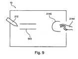
- a copy combined gesturemay include two fingers 2144 tracking out a 'C' shape 2145 and subsequently remaining on the screen while stylus 212 underlines a portion of the contents of screen 10 to be copied, e.g. text 543 displayed on the screen.
- a combined gesture for a bold command to bold lettersincludes performing a pre-defined gesture with a finger while and/or directly after writing letters with the stylus. Letters written will be displayed in bold.
- a gesturemay be made with the stylus while the parameter for the gesture may be defined with a finger touch.
- at least one of the user interactionsperforms a gesture and/or an event while hovering over the digitizer sensor.
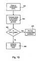
- a combination event including a stylus and a finger touchis detected (block 940).
- the combination eventmay be a simultaneous stylus and finger event.
- the combination eventmay be a stylus event that immediately follows a finger event and/or a finger event that immediately follows a stylus event.
- the combination eventmay include a finger event followed by a simultaneous finger and stylus event or a stylus event followed by a simultaneous finger and stylus event.
- the detected combination eventis compared to pre-defined gestures (block 950).
- a gesture recognition engineis implemented to determine if a detected combination event matches one of the pre-defined combination gestures.
- the gesture recognition engine and/or its functionalityare integrated in the controller of the digitizer sensor, e.g. ASIC 16 and/or ASIC 20.
- a queryis made to determine if the detected combination event is a pre-defined combination gesture, e.g. user defined and/or system pre-defined (block 960).
- the corresponding commandis applied and/or executed.
- an indicationis given to the user as to which gesture was recognized prior to executing the relevant command.
- a usermay perform a verification gesture to indicate that the recognized gesture is the intended gesture.
- the eventis considered a standard user interaction event and/or standard input (block 980).
Landscapes
- Engineering & Computer Science (AREA)
- General Engineering & Computer Science (AREA)
- Theoretical Computer Science (AREA)
- Human Computer Interaction (AREA)
- Physics & Mathematics (AREA)
- General Physics & Mathematics (AREA)
- User Interface Of Digital Computer (AREA)
Description
- The present invention relates to a digitizer, and more particularly to stylus and fingertip touch sensitive digitizers.
- Touch technologies are commonly used as input devices for a variety of products. The usage of touch devices of various kinds is growing sharply due to the emergence of new mobile devices such as Personal Digital Assistants (PDA), tablet PCs and wireless flat panel displays (FPD). Some of these devices are not connected to standard keyboards, mice or like input devices, which are deemed to limit their mobility. Instead there is a tendency to use touch input technologies of one kind or another. A stylus and/or finger may be used as a user interaction. One or more pre-defined gestures with the stylus or finger may be supported to convey specific user commands to the system.
US Patent No. 6,791,536 , entitled "Simulating Gestures of a Pointing Device using a Stylus and Providing Feedback Thereto", assigned to Microsoft Corporation, describes a system and method for simulating gestures using a stylus and choosing an action to be performed in response to the stylus gesture.US Patent No. 6,690,156 entitled "Physical Object Location Apparatus and Method and a Platform using the same" andUS Patent Publication No. 20040095333 entitled "Transparent Digitizer" both of which are assigned to N-trig Ltd., describe an electro-magnetic method for locating physical objects on a FPD and a transparent digitizer that can be incorporated into an electronic device, typically over the active display screen. The digitizer sensor includes a matrix of vertical and horizontal conducting lines to sense an electric signal. Positioning the physical object at a specific location on the digitizer provokes a signal whose position of origin may be detected.U.S, Patent Application Publication No. 20040155871 entitled "Touch Detection for a Digitizer" assigned to N-trig Ltd, describes a digitizing tablet system capable of detecting position of physical objects and/or fingertip touch using the same sensing conductive lines. Simultaneous position detection of physical objects and fingertip is supported. Typically, the system includes a transparent sensor overlaid on a FPD. The digitizer's sensor includes a matrix of vertical and horizontal conducting lines to sense an electric signal. Touching the digitizer in a specific location provokes a signal whose position of origin may be detected.U.S. Patent Application Publication No. 20060012580 , entitled "Automatic switching for a dual mode digitizer" assigned to N-Trig, describes a method handling different types of user interactions, e.g. electromagnetic stylus and finger touch, in a digitizer system. In some examples, a gesture is used to indicate a switch between user interactions.- International Patent Publication No.
WO2006/006173 , entitled "Automatic Switching for Dual Mode Digitizer" assigned to N-Trig, describes an apparatus for detecting a plurality of user interactions. The apparatus includes at least one detector for sensing the user interactions, a respective controller, associated with each of the detectors, for finding positions of the user interactions, and a switcher associated with the controller for handling the user interactions, according to a defined policy. It is described that if the user interaction is is a stylus, the digitizer supports full mouse emulation. As long as the stylus hovers above the screen, a mouse cursor follows the stylus position. Touching the screen with the stylus stands for left click and a dedicated switch located on the stylus emulates right click operation. - An aspect of some embodiments of the invention is the provision of a digitizer system and a method for distinguishing between gesture input signals and other digitizer generated signals that are not intended to be interpreted as a pre-defined gesture. As used herein the term gesture is a purposeful pre-defined motion that a user makes to indicate a command to the system. Implementation of gestures for interacting with the digitizer system can be used to increase the functionality of the system and increase speed of a user's interaction with the system.
- According to some embodiments of the present invention, a method is provided for detecting and/or implementing a gesture where the gestures is a combination event including a finger touch and a stylus. Gestures supported by known systems are performed with a single user interaction, e.g. a stylus and/or finger. The number of pre-defined gestures (and thus, actions or operations) that can be defined with a single user interaction may be limited. In addition, an input signal from pre-defined gestures performed with a single user interaction may at times be mistaken for a regular input signal not intended to be defined as a gesture and/or for another pre-defined gesture.
- According to some embodiments of the present invention, combination gestures are defined and implemented for conveying pre-defined user input data and/or commands to the digitizer system. Combination gestures are defined as pre-defined gestures including two different types of user interactions, e.g. both finger and stylus user interaction or multiple unconnected motions of one or both of a stylus and finger, performed simultaneously or sequentially. Optionally, the stylus user interaction can be replaced by another type of user interaction, e.g. a game piece and used to define and/or convey a combination gesture. Optionally, the finger user interaction can be replaced by an alternate body part user interaction, e.g. a hand user interaction. For example a combination gesture including input signals from game piece and user's hand may be defined.
- According to some embodiments of the present invention, a combination gesture is a pre-defined finger and stylus event performed substantially simultaneously. According to some embodiments, a combination gesture is a pre-defined finger event and stylus event performed sequentially, e.g. a finger event directly followed by a stylus event or a stylus event directly followed by a finger event. In some exemplary embodiments one event, e.g. finger or stylus, follows the other event of the combination within a pre-defined time period. According to some exemplary embodiments, pre-defined finger and/or stylus events that are used to make up a combination gesture may include either hover and/or touch interaction with the digitizer.
- According to some embodiments of the present invention, a combination gesture is a two part combination gesture, where one user interaction is used to perform the gesture that defines the user specified command, e.g. copy, paste, shift, zoom, while the other user interaction defines a parameter of the command, e.g. the text to be copied or pasted, letters to be typed in capital and, zoom level. According to some exemplary embodiments, the first user interaction performing the gesture and the second user interaction specifying a parameter of the gesture are pre-defined, e.g. by the user and/or the system. In some exemplary embodiments, the elements and/or events of the two part combination gesture is performed substantially simultaneously. In some exemplary embodiments, the events of two part combination gesture are performed sequentially, e.g. first by the first user interaction performing the gesture and immediately afterwards by the second user interaction specifying a parameter of the gesture.
- According to some embodiments of the present invention, detection of a combination finger and stylus user input, triggers gesture detection, e.g. with a gesture recognition engine, to identify the detected event as a pre-defined gesture. The detected combination finger and stylus input signal may be compared to a database of pre-defined combination gestures for identification. Typically, successful identification provokes execution of a command associated with the identified pre-defined gesture. Optionally, identification and/or recognition of a gesture may be conveyed to the user prior to executing corresponding command associated with the identified gesture. Optionally, failure to recognize a gesture as a pre-defined gesture is conveyed to the user. Optionally, gestures may be pre-defined and/or user defined based on a pre-defined set of rules.
- An aspect of some embodiments of the present invention provides for a method for detecting combination gestures with a digitizer, the method comprising storing a database of pre-defined combination gestures, wherein the combination gestures includes input from two different types of user interactions, detecting a combination event, wherein the combination event includes input from the two different types of user interactions, and matching input from the combination event to a pre-defined gesture from the database of pre-defined combination gestures.
- Optionally, at least part of the input from the two different types of user interactions of the combination gesture is detected substantially simultaneously.
- Optionally, the input from the two different types of user interactions of the combination gesture is detected sequentially.
- Optionally, a gesture performed with one of the two different types of user interactions is associated with a pre-defined user command and the input from the other type of user interaction is associated with a parameter of the pre-defined user command.
- Optionally, the two different types of user interactions include a body part and an inanimate object.
- Optionally, the body part is selected from a group consisting of a finger and a hand.
- Optionally, the inanimate object is selected from a group consisting of a stylus and a game piece.
- Optionally, the inanimate object is a conductive object.
- Optionally, the inanimate object is an electromagnetic object.
- Optionally, the object includes passive circuitry that can be excited by an external excitation source.
- Optionally, at least part of the input is input derived from touching the digitizer.
- Optionally, at least part of the input is input derived from hovering over the digitizer.
- Optionally, the method comprises requesting verification from a user that a matched combination gesture from the pre-defined combination gesture is an intended combination gesture.
- Optionally, the method provides conveying recognition of the combination gesture to a user.
- Optionally, at least one pre-defined combination gesture in the database is a user defined combination gesture.
- Optionally, at least one pre-defined combination gesture in the database is a system pre-defined combination gesture.
- Optionally, the method comprises executing a command indicated by the pre-defined gesture from the database.
- An aspect of some embodiments of the present invention provides for a method for detecting combination gestures with a digitizer, the method comprising storing a database of pre-defined combination gestures, wherein the combination gestures includes input from two different types of user interactions, detecting a combination event, wherein the combination event includes input from the two different types of user interactions, matching input from one type of user interaction of the two different type of user interactions with a pre-defined gesture associated with a pre-defined user command, and matching input from the other type of user interaction with a parameter value associated with the pre-defined user command.
- Optionally, the two different types of user interactions include a body part and an inanimate object.
- Optionally, the body part is selected from a group consisting of a finger and a hand.
- Optionally, the inanimate object is selected from a group consisting of a stylus and a game piece.
- Optionally, input from the body part is matched with the pre-defined gesture and wherein input from the inanimate object is matched with the parameter value.
- Optionally, input from the inanimate object is matched with the pre-defined gesture and wherein input from the body part is matched with the parameter value.
- Optionally, the input from the two different types of user interactions is performed substantially simultaneously.
- Optionally, the input from the two different types of user interactions is performed one after the other.
- An aspect of some embodiments of the present invention provides for system for detecting combination gestures with a digitizer system, the digitizer system comprising at least one digitizer configured for detecting input from two different types of user interactions, and a memory unit configured for storing a database of pre-defined combination gestures, wherein the pre-defined combination gestures are associated with pre-defined user commands, and a controller configured for matching input from the two different types of user interactions with a pre-defined combination gesture from the database.
- Optionally, the memory unit is integral to the digitizer.
- Optionally, the controller is integral to the digitizer.
- Optionally, the controller includes functionality of a gesture recognition engine.
- Optionally, the digitizer is configured to detect hovering of at least one of the two different types of user interactions.
- Optionally, the digitizer is configured to detect touch of at least one of the two different types of user interactions.
- Optionally, the two different types of user interactions include a body part and an inanimate object.
- Optionally, the body part is selected from a group consisting of a finger and a hand.
- Optionally, the inanimate object is selected from a group consisting of a stylus and a game piece.
- Optionally, the inanimate object includes passive circuitry that can be excited by an external excitation source.
- Optionally, the digitizer is configured for capacitive-based detection.
- Optionally, the system comprises a host computer, wherein the host computer is configured to receive input from the digitizer.
- Optionally, the controller is integral to the host computer.
- Optionally, the memory unit is integral to the host computer.
- Optionally, the pre-defined combination gestures are interpreted as pre-defined user commands to the host computer.
- Optionally, at least part of the input from the two different types of user interactions of the combination gesture is detected substantially simultaneously.
- Optionally, the input from the two different types of user interactions of the combination gesture is detected sequentially.
- Optionally, wherein the digitizer comprises a digitizer sensor and wherein the input from the two different types of user interactions is detected from the digitizer sensor.
- Optionally, the digitizer sensor comprises a patterned arrangement of conducting lines and wherein input from the two types of user interactions are detected from at least one conducting line of the patterned arrangement of conducting lines.
- Optionally, the digitizer comprises at least two digitizer sensors wherein the two different types of user interactions are detected from different digitizer sensors from the at least two digitizer sensors.
- Optionally, the system comprises a plurality of digitizers wherein the two different types of user interactions are detected from different digitizers from the plurality of digitizers.
- The subject matter regarded is particularly and distinctly claimed in the concluding portion of the specification. Non-limiting examples of embodiments of the present invention are described below with reference to figures attached hereto, which are listed following this paragraph. In the figures, identical structures, elements or parts that appear in more than one figure are generally labeled with a same symbol in all the figures in which they appear. Dimensions of components and features shown in the figures are chosen for convenience and clarity of presentation and are not necessarily shown to scale. For example, the dimensions of some of the elements may be exaggerated relative to other elements for clarity.
Figure 1 is an exemplary simplified block diagram of a digitizer system in accordance with some embodiments of the present invention;Figure 2 is an exemplary simplified circuit diagram for touch detection based on a capacitive touch method according to some embodiments of the present invention;Figure 3 is an exemplary simplified circuit diagram of a digitizer sensor including differential amplifiers according to some embodiments of the present invention;Figure 4 is a schematic illustration of a digitizer sensor for finger touch detection based on a junction capacitive touch method, according to some embodiments of the present invention;Figures 5A and 5B are exemplary 'zoom in' and 'zoom out' combination gestures using stylus and finger touch according to some embodiments of the present invention;Figures 6A and 6B are exemplary 'scroll down' and 'scroll up' combination gestures using stylus and finger touch according to some embodiments of the present invention;Figures 7A and 7B are exemplary 'rotate clockwise' and 'rotate counter-clockwise' combination gestures using stylus and finger touch according to some embodiments of the present invention;Figures 8A and 8B showing an exemplary combination gesture that can be distinguished from a similar single user interaction gesture according to some embodiments of the present invention; andFigure 9 showing an exemplary two stage combination gesture according to some embodiments of the present invention;Figure 10 is an exemplary flow chart of a method for recognizing a combination gesture according to some embodiments of the present invention.- It will be appreciated that for simplicity and clarity of illustration, elements shown in the figures have not necessarily been drawn to scale. Further, where considered appropriate, reference numerals may be repeated among the figures to indicate corresponding or analogous elements.
- In the following description, exemplary, non-limiting embodiments of the invention incorporating various aspects of the present invention are described. For purposes of explanation, specific configurations and details are set forth in order to provide a thorough understanding of the embodiments. However, it will also be apparent to one skilled in the art that the present invention may be practiced without the specific details presented herein. Furthermore, well-known features may be omitted or simplified in order not to obscure the present invention. Features shown in one embodiment may be combined with features shown in other embodiments. Such features are not repeated for clarity of presentation. Furthermore, some unessential features are described in some embodiments.
- Reference is now made to
Fig. 1 showing an exemplary simplified block diagram of a digitizer system in accordance with some embodiments of the present invention. Thedigitizer system 100 shown inFig. 1 may be suitable for any computing device that enables interactions between a user and the device, e.g. mobile computing devices that include, for example, FPD screens. Examples of such devices include Tablet PCs, pen enabled lap-top computers, PDAs or any hand held devices such as palm pilots and mobile phones. According to some embodiments of the present invention, the digitizer system comprises asensor 12 including a patterned arrangement of conducting lines, which is optionally transparent, and which is typically overlaid on aFPD 10. Typicallysensor 12 is a grid based sensor including horizontal and vertical conducting lines. - An
ASIC 16 comprises circuitry to process and sample the sensor's output into a digital representation. The digital output signal is forwarded to adigital unit 20, e.g. digital ASIC unit, for further digital processing. According to some embodiments of the present invention,digital unit 20 together withASIC 16 serve as the controller of the digitizer system and/or have functionality of a controller and/or processor. The outcome, once determined, is forwarded to ahost 22 via aninterface 24 for processing by the operating system or any current application. According to some embodiments of the present invention, control functionality is additionally or exclusively included in thehost 22.ASIC 16 anddigital unit 20 may be provided as a single ASIC. According to some embodiments of the present invention,digital unit 20 together withASIC 16 include memory and/or memory capability. - According to some embodiments of the present invention,
sensor 12 comprises a grid of conductive lines made of conductive materials, optionally Indium Tin Oxide (ITO), patterned on a foil or glass substrate. The conductive lines and the foil are optionally transparent. Typically, the grid is made of two layers, which are electrically separated from each other. Typically, one of the layers contains a set of equally spaced parallel conductors and the other layer contains a set of equally spaced parallel conductors orthogonal to the set of the first layer. Typically, the parallel conductors are equally spaced straight lines, and are input to amplifiers included inASIC 16. Optionally the amplifiers are differential amplifiers. Typically, the parallel conductors are spaced at a distance of approximately 2-8 mm, e.g. 4mm, optionally depending on the size of the FPD and a desired resolution. Optionally the region between the grid lines is filled with a non-conducting material having optical characteristics similar to the conducting lines, to mask the presence of the conducting lines. - Typically,
ASIC 16 is connected to outputs of the various conductors in the grid and functions to process the received signals at a first processing stage. As indicated above,ASIC 16 typically includes an array of amplifiers, e.g. differential amplifiers, to amplify the sensor's signals. Additionally,ASIC 16 optionally includes one or more filters to remove irrelevant frequencies. Optionally, filtering is performed prior to sampling. The signal is then sampled by an A/D, optionally filtered by a digital filter and forwarded to digital ASIC unit, for further digital processing. Alternatively, the optional filtering is fully digital or fully analog. - According to some embodiments of the invention,
digital unit 20 receives the sampled data fromASIC 16, reads the sampled data, processes it and determines and/or tracks the position of physical objects, such as stylus, and/or finger, touching the digitizer sensor. According to some embodiments of the present invention hovering of an object, e.g. stylus, finger and hand, is also detected and processed bydigital unit 20. Calculated position is sent to the host computer viainterface 24. - According to some embodiments,
digital unit 20 produces and manages a triggering pulse to be provided to anexcitation coil 26 that surrounds the sensor arrangement and the display screen. The excitation coil provides a trigger pulse (in the form of an electric or electromagnetic field) that excites passive circuitry in the stylus to produce a response from the stylus that can subsequently be detected. - According to some embodiments,
digital unit 20 produces and sends a triggering pulse to at least one of the conductive lines. - According to some embodiments of the invention,
host 22 includes at least amemory unit 23 and aprocessing unit 25 to store and process information obtained fromASIC 16. Memory and processing capability is also generally included indigital unit 20 andASIC 16. According to some embodiments of the present invention memory and processing functionality may be divided between any two or three ofhost 22,digital unit 20, andASIC 16 or may reside in only one of them. - According to some embodiments of the present invention the digitizer system may include one or more digitizers associated with a
single host 22. In some exemplary embodiments the digitizer includes at least thedigitizer sensor 12,ASIC units 16 anddigital unit 20. - According to some embodiments of the present invention, the stylus is a passive element. Optionally, the stylus comprises a resonant circuit, which is triggered by
excitation coil 26 to oscillate at its resonant frequency. At the resonant frequency, the circuit produces oscillations that continue after the end of the excitation pulse and steadily decay. While the stylus touches and/or hovers overdigitizer 20, the decaying oscillations induce a voltage in nearby conductive lines which are sensed bysensor 12. Alternatively, the stylus may include an energy pick-up unit and an oscillator circuit. - According to some embodiments of the present invention, two parallel sensor lines that are close but not adjacent to one another are connected to the positive and negative input of a differential amplifier respectively. The amplifier is thus able to generate an output signal which is an amplification of the difference between the two sensor line signals. An amplifier having a stylus on one of its two sensor lines will produce a relatively high amplitude output. Stylus detection is described with further details, for example in
US Patent Application Publication 20040095333 . - Reference is now made to
Fig. 2 showing an exemplary circuit diagram for touch detection according to some embodiments of the present invention.Conductive lines sensor 12. According to some embodiments of the present invention,conductive lines common ground 350. When a finger is placed on one of the conductive lines of the pair, a capacitance, CT, develops between the finger (either touching or hovering over the digitizer) andconductive line 310. As there is a potential between theconductive line 310 and the user's finger, current passes from theconductive line 310 through the finger to ground. Consequently a potential difference is created betweenconductive line 310 and itspair 320, both of which serve as input todifferential amplifier 340. Finger touch detection is described with further details in, for example incorporatedUS Patent Application Publication 20040155871 . Typically parasitic capacitance develops between the display screen and the conductive lines of the overlaying digitizer sensor. Typically parasitic capacitance induces a current leakage into the conductive lines of the digitizer referred to as a "steady noise" and/or steady state noise. In an ideal environment, the parasitic capacitance and therefore the steady state noise level in each of the lines are expected to be identical. However, in practice slight differences in distance between the digitizer and screen, material structure in specific areas of the digitizer screen, environmental conditions and parasitic capacitance on associated PCB, may affect the parasitic capacitance level between the screen and some of the lines. The unbalanced capacitance creates an unbalance steady state noise level of the lines. A system and method for balancing capacitance is described inUS Patent Application Publication No. 20070268272 , entitled "Variable Capacitor Array" which is assigned to the common assignee. The systems and methods described inUS Patent Application Publication No. 20070268272 . may be applied to the present invention. - Reference is now made to
Fig. 3 showing an array of conductive lines of the digitizer sensor as input to differential amplifiers according to embodiments of the present invention. Separation between the twoconductive lines differential amplifier 340 amplifies the potential difference developed betweenconductive lines ASIC 16 anddigital unit 20 process the amplified signal and determine the location and/or position of the user's finger based on the amplitude and/or signal level of the sensed signal. - In one example, the origin of the user's finger from the two inputs of the differential amplifier is determined by examining the phase of the output. In another example, since a finger touch typically produces output in more than one conductive line, the origin of the user's finger from the two inputs of the differential amplifier is determined by examining outputs of neighboring amplifiers and optionally interpolating is used to find a more accurate value. In yet other examples, a combination of both methods may be implemented.
- Reference is now made to
Fig. 4 which schematically illustrates a capacitive junction touch method for finger touch detection using a digitizer sensor, according to some embodiments of the present invention. At each junction, e.g. ajunction 40 in sensor 12 a minimal amount of capacitance exists between orthogonal conductive lines. In an exemplary embodiment, anAC signal 60 is applied to one or more parallel conductive lines in the two-dimensional sensor matrix 12. When afinger 41 touches or hovers over the sensor at a certain position where asignal 60 is induced, the capacitance between the conductive line through which signal 60 is applied and the corresponding orthogonal conductive lines at least proximal to the touch and/or hover position increases and signal 60 is coupled, by the capacitance offinger 41, to corresponding orthogonal conductive lines to produce and anoutput signal 65. This method is able to detect more than one finger touch and/or hover at the same time (multi-touch). This method further enables calculating touch and/or hover area. In exemplary embodiments of the present invention, each conductive line is input to an amplifier. Optionally, one line is input to a differential amplifier, while the other input to the amplifier is ground. Optionally, both lines of the pair are input to the differential amplifier and a same interrogating signal is transmitted over both lines of the pair. Typically, the presence of a finger touch decreases the coupled signal by 20-30% since the capacitive coupling caused by the finger typically drains current from the lines. The presence of a finger hovering may decrease the couple signal less drastically. - According to some embodiments of the present invention, a finger and/or
hand 41 placed in proximity over the digitizer sensor at a height (h), forms a capacitance between the finger and/or hand andsensor 12 through the air, provided that the finger and/or hand is close to the sensor, i.e., for small heights. The presence of the finger and/or hand increases the capacitance between a conductive and the orthogonal conductive line which is at or close to the finger and/or hand position. As the signal is AC, the signal crosses at a junction by virtue of the capacitance of the finger and/or hand from the conductive line to the corresponding orthogonal conductive line forming the junction, andoutput signal 65 is detected. According to some exemplary embodiments, the digitizer system can simultaneously detect and track a plurality of hovering objects. - It will be appreciated that depending on the size of the finger/hand and the fineness of the mesh of conductors, a plurality of the orthogonal conductors may receive some capacitive signal transfer, and interpolation of the signal between the conductors can be used to increase measurement accuracy.
- The present invention is not limited to the technical description of the digitizer system described herein. Digitizer systems used to detect stylus and/or finger touch location may be, for example, similar to digitizer systems described in
U.S. Patent No. 6,690,156 ,U.S. Patent Application Publication No. 20040095333 and/orU.S. Patent Application Publication No. 20040155871 . It will also be applicable to other digitized sensor and touch screens known in the art, depending on their construction. In some exemplary embodiment, a digitizer system may include two or more sensors. For example, one digitizer sensor may be configured for stylus detecting and/or tracking while a separate and/or second digitizer sensor may be configured for finger and/or hand detection. In other exemplary embodiments, portions of a digitizer sensor may be implemented for stylus detection and/or tracking while a separate portion may be implemented for finger and/or hand detection. - According to some embodiments of the present invention, pre-defined stylus and finger combination gestures are defined and implemented to execute one or more digitizer and/or system commands. In some exemplary embodiments, a stylus and finger combination gesture is implemented to perform a zoom, scroll, rotate and/or other commands. According to some embodiments of the present invention, commands and/or corresponding combination gestures may be system defined and/or user defined. According to some embodiments of the present invention, system defined gestures are intuitive gestures that emulate the associated command indicated by the gesture.
- According to some embodiments of the present invention, features of one or more combination gesture input signals are stored in memory, e.g. digitizer memory incorporated in one or more ASIC units (
ASIC 16 and/or ASIC 20) ofdigitizer system 100. According to some embodiments of the present invention, a database of features to be implemented to recognize one or more combination gestures is stored. Typically, storing is performed at the level of the digitizer sensor. Optionally, the database may be stored inhost 22 of the digitizer system. Combination gestures may be pre-defined gestures defined by the system and/or may be user defined gestures. - According to some embodiments of the present invention, recognition of the combination gestures may be performed on the level of the digitizer sensor using processing capability provided by one or more ASIC units and/or other units of the digitizer sensor, e.g.
ASIC unit 16 and/orASIC unit 20. Optionally, recognition is performed at least partially on the level ofhost 22 using processing capability of the host computer,e.g. memory unit 25. - Reference is now made to
Fig. 5A and 5B showing exemplary 'zoom in' and 'zoom out' combination gestures using stylus and finger touch according to some embodiments of the present invention. According to some embodiments of the present invention, a 'zoom in' gesture schematically illustrated inFig. 5A includes input from both astylus 212 and afinger 214, e.g. substantially simultaneously input. In some exemplary embodiments, the finger and stylus may perform a diverging motion from a common area and/orposition 215 on ascreen 10 at some angle in the direction ofarrows host 22 responds by executing 'zoom in' command in anarea surrounding position 215 from which the combination gesture began, e.g. the common area. In other exemplary embodiments, the area between the end points of the 'V' shaped tracking curve defines the area to be zoomed. - According to some embodiments of the present invention, a 'zoom out' combination gesture schematically illustrated in
Fig. 5B includes astylus 212 and afinger 214 substantially simultaneously converging to a common area and/orposition 215 from different angles in the direction ofarrows - According to some embodiments of the present invention, the digitizer system translates the angle of the 'V' shaped motion to an approximate zoom level. In one exemplary embodiment a wide 'V' shaped angle is interpreted as a large zoom level while a sharp 'V' shaped angle is interpreted in a small zoom level. In one exemplary embodiment, three zoom levels may be represented by sharp medium and wide angle 'V' shaped motion. The angles for each of the zoom levels may be pre-defined and/or user customized. In some exemplary embodiments of the present invention, the system may implement a pre-defined zoom ratio for each new user and later calibrate the system based on corrected values offered by the user. In some exemplary embodiments, the zoom level may be determined separately subsequent to recognition of the zoom gesture, e.g. based on subsequent input by the user. According to some embodiments of the present invention, the 'zoom in' and/or 'zoom out' gesture is defined as a hover combination gesture where the 'V' shaped motion is performed with the stylus and/or finger hovering over the digitizer sensor.
- Reference is now made to
Fig. 6A and 6B showing exemplary 'scroll up' and 'scroll down' combination gestures using stylus and finger touch according to some embodiments of the present invention. According to some embodiments of the present invention, a 'scroll up' gesture schematically illustrated inFig. 6A includesstylus 212 andfinger 214 substantially simultaneous motioning in a common upward direction as indicated byarrow digitizer system screen 10. According to some embodiments of the present invention, a 'scroll up' gesture schematically illustrated inFig. 6B includesstylus 212 andfinger 214 substantially simultaneously motioning in a common downward direction as indicated byarrow digitizer system screen 10. Optionally, left and right scroll gestures are defined as simultaneous stylus and finger motion in a corresponding left and/or right direction. In response to a recognized scroll gesture, the display is scrolled in the direction of the movement of the stylus and finger. In some exemplary embodiments of the present invention, gestures for combination vertical and horizontal scrolling may be implemented, e.g. simultaneous stylus and finger motion at an angle. In some exemplary embodiments of the present invention, the length of the tracking curve of the simultaneous motion of the stylus and finger in a common direction may be indicative of the amount of scrolling desired and/or the scrolling speed. In one exemplary embodiment, a long tracking curve, e.g. spanning substantially the entire screen may be interpreted as a command to scroll to the limits of the document, e.g. beginning and/or end of the document (depending on the direction). In one exemplary embodiment, a short tracking curve, e.g. spanning less than 1/2 the screen, may be interpreted as a command to scroll to the next screen and/or page. Features of the scroll gesture may be pre-defined and/or user defined. According to some embodiments of the present invention, scrolling may be performed using hover motion tracking such that the stylus and/or finger perform the gesture without touching the digitizer screen and/or sensor. - Reference is now made to
Fig. 7A and 7B showing exemplary 'rotate clockwise' and 'rotate counter-clockwise' combination gestures using stylus and finger touch according to some embodiments of the present invention. According to some embodiments of the present invention, a 'rotate clockwise' gesture schematically illustrated inFig. 7A includesstylus 212 andfinger 214 substantially simultaneous motioning in a clockwise direction as indicated byarrow 333 and 336, e.g. drawing a curve in a clockwise direction, where the motion originates from vertically spacedpositions Fig. 7B includesstylus 212 andfinger 214 substantially simultaneously motioning in a counter-clockwise direction as indicated byarrow positions - Reference is now made to
Fig. 8A showing an exemplary combination gesture that can be distinguished from a similar single user interaction gesture shown inFig. 8B according to some embodiments of the present invention. According to one exemplary embodiment of the present invention,Fig. 8A illustrates a copy command combination gesture including astylus 212 and afinger 214 andFig. 8B illustrates a cut command gesture with a single user interaction, e.g. astylus 212. In bothFig. 8A and 8B the stylus forms the same gesture, e.g. a 'C' shapedtracking curve 433. The command for copy and cut is distinguished based on input from thefinger 214. Recognition of the presence of the finger touch or hovering shown inFig. 8A indicates a copy command while the absence of the finger touch such as is the case inFig. 8B indicates that the gesture is a cut gesture. In some exemplary embodiments, the extent of the cut or copy gestures, e.g. how much is cut or copied, may depend on the extent of the gestures. - Reference is now made to
Fig. 9 showing an exemplary two stage combination gesture according to some embodiments of the present invention. In one exemplary embodiment of the present invention, a two part combination gesture is defined for performing a copy command. In one exemplary embodiment, a copy combined gesture may include twofingers 2144 tracking out a 'C'shape 2145 and subsequently remaining on the screen whilestylus 212 underlines a portion of the contents ofscreen 10 to be copied,e.g. text 543 displayed on the screen. In another exemplary embodiment, a combined gesture for a bold command to bold letters includes performing a pre-defined gesture with a finger while and/or directly after writing letters with the stylus. Letters written will be displayed in bold. Optionally, a gesture may be made with the stylus while the parameter for the gesture may be defined with a finger touch. Optionally, at least one of the user interactions performs a gesture and/or an event while hovering over the digitizer sensor. - Reference is
Figure 10 exemplary flow chart of a method for recognizing a combination gesture according to some embodiments of the present invention. According to some embodiments of the present invention, a combination event including a stylus and a finger touch is detected (block 940). In some exemplary embodiments, the combination event may be a simultaneous stylus and finger event. In some exemplary embodiments, the combination event may be a stylus event that immediately follows a finger event and/or a finger event that immediately follows a stylus event. In some exemplary embodiment, the combination event may include a finger event followed by a simultaneous finger and stylus event or a stylus event followed by a simultaneous finger and stylus event. The detected combination event is compared to pre-defined gestures (block 950). In one exemplary embodiment a gesture recognition engine is implemented to determine if a detected combination event matches one of the pre-defined combination gestures. In some embodiments, the gesture recognition engine and/or its functionality are integrated in the controller of the digitizer sensor, e.g.ASIC 16 and/orASIC 20. A query is made to determine if the detected combination event is a pre-defined combination gesture, e.g. user defined and/or system pre-defined (block 960). According to some embodiments of the present invention, for a positive match, the corresponding command is applied and/or executed. According to some embodiments of the present invention, when a detected event is recognized as one of the pre-defined combination gestures, an indication is given to the user as to which gesture was recognized prior to executing the relevant command. In one exemplary embodiment, a user may perform a verification gesture to indicate that the recognized gesture is the intended gesture. According to some embodiments of the present invention, for cases when a combination event is not recognized as a pre-defined combination gesture, the event is considered a standard user interaction event and/or standard input (block 980). - It should be further understood that the individual features described hereinabove can be combined in all possible combinations and sub-combinations to produce exemplary embodiments of the invention. Furthermore, not all elements described for each embodiment are essential. In many cases such elements are described so as to describe a best more for carrying out the invention or to form a logical bridge between the essential elements. The examples given above are exemplary in nature and are not intended to limit the scope of the invention which is defined solely by the following claims.
- The terms "include", "comprise" and "have" and their conjugates as used herein mean "including but not necessarily limited to".
Claims (14)
- A method for detecting gestures with a digitizer, the method comprising:storing a database of pre-defined gestures, wherein the pre-defined gestures includes input from a body part and an inanimate object, the inanimate object emitting a signal detected by the digitizer;detecting an event, wherein the event includes input from the body part and the inanimate object;distinguishing between input from the body part and input from the inanimate object; andmatching input from the event to a pre-defined gesture from the database of pre-defined gestures.
- The method according to claim 1, wherein at least part of the input from the body part and the inanimate object of the gesture is detected substantially simultaneously.
- The method according to claim 1 or claim 2, wherein input from one of the body part and the inanimate object is associated with a pre-defined user command and input from the other one of the body part and the inanimate object is associated with a parameter of the pre-defined user command.
- The method according to any of claims 1-3, wherein the body part is selected from a group consisting of at least one finger and a hand.
- The method according to claim 4, wherein the input from the body part is a drain in current from the digitizer due to capacitive coupling between the body part and the digitizer.
- The method according to any of claims 1-5, wherein the inanimate object is selected from a group consisting of a stylus, a conductive object and a game piece.
- The method according to claim 6, wherein the input from the stylus is an oscillating signal that induces a voltage in the digitizer.
- The method according to any of claims 1-7, wherein at least part of the input is input derived from touching the digitizer.
- The method according to any of claims 1-8, wherein at least part of the input is input derived from hovering over the digitizer.
- The method according to any of claims 1-9 comprising executing a command indicated by the pre-defined gesture from the database.
- A system for detecting gestures with a digitizer system, the digitizer system comprising:at least one digitizer sensor configured for detecting an event, wherein the event includes input from both a body part and input from an inanimate object, the inanimate object emitting a signal detected by the digitizer;a memory unit configured for storing a database of pre-defined gestures, wherein the pre-defined gestures are associated with pre-defined user commands; anda controller configured for matching inputs from the event with a pre-defined gesture from the database, wherein the controller is operative to distinguish between input from the body part and input from the inanimate object.
- The system according to claim 11, wherein the digitizer is configured for detecting substantially simultaneous input from the body part and the inanimate object.
- The system according to any of claims 10-11, wherein the controller is configured for matching input from one of the body part and the inanimate object with the pre-defined user command and the input from the other one of the body part and the inanimate object with a parameter of the pre-defined user command.
- The system according to any of claims 10-13 comprising a plurality of digitizers wherein the body part and the inanimate object are detected by different digitizers from the plurality of digitizers
Applications Claiming Priority (2)
| Application Number | Priority Date | Filing Date | Title |
|---|---|---|---|
| US83763006P | 2006-08-15 | 2006-08-15 | |
| PCT/IL2007/001025WO2008020446A1 (en) | 2006-08-15 | 2007-08-15 | Gesture detection for a digitizer |
Publications (2)
| Publication Number | Publication Date |
|---|---|
| EP2057527A1 EP2057527A1 (en) | 2009-05-13 |
| EP2057527B1true EP2057527B1 (en) | 2013-05-22 |
Family
ID=38543633
Family Applications (1)
| Application Number | Title | Priority Date | Filing Date |
|---|---|---|---|
| EP07805486.3ANot-in-forceEP2057527B1 (en) | 2006-08-15 | 2007-08-15 | Gesture detection for a digitizer |
Country Status (5)
| Country | Link |
|---|---|
| US (1) | US20080046425A1 (en) |
| EP (1) | EP2057527B1 (en) |
| JP (1) | JP4514830B2 (en) |
| DE (1) | DE202007018940U1 (en) |
| WO (1) | WO2008020446A1 (en) |
Families Citing this family (118)
| Publication number | Priority date | Publication date | Assignee | Title |
|---|---|---|---|---|
| GB9722766D0 (en) | 1997-10-28 | 1997-12-24 | British Telecomm | Portable computers |
| US8018440B2 (en) | 2005-12-30 | 2011-09-13 | Microsoft Corporation | Unintentional touch rejection |
| US20080168402A1 (en) | 2007-01-07 | 2008-07-10 | Christopher Blumenberg | Application Programming Interfaces for Gesture Operations |
| US20080168478A1 (en) | 2007-01-07 | 2008-07-10 | Andrew Platzer | Application Programming Interfaces for Scrolling |
| US7844915B2 (en) | 2007-01-07 | 2010-11-30 | Apple Inc. | Application programming interfaces for scrolling operations |
| US8219936B2 (en)* | 2007-08-30 | 2012-07-10 | Lg Electronics Inc. | User interface for a mobile device using a user's gesture in the proximity of an electronic device |
| US8432365B2 (en)* | 2007-08-30 | 2013-04-30 | Lg Electronics Inc. | Apparatus and method for providing feedback for three-dimensional touchscreen |
| US9367166B1 (en)* | 2007-12-21 | 2016-06-14 | Cypress Semiconductor Corporation | System and method of visualizing capacitance sensing system operation |
| US8416196B2 (en) | 2008-03-04 | 2013-04-09 | Apple Inc. | Touch event model programming interface |
| US8645827B2 (en) | 2008-03-04 | 2014-02-04 | Apple Inc. | Touch event model |
| US8717305B2 (en) | 2008-03-04 | 2014-05-06 | Apple Inc. | Touch event model for web pages |
| US20090327974A1 (en)* | 2008-06-26 | 2009-12-31 | Microsoft Corporation | User interface for gestural control |
| US8347230B2 (en)* | 2008-09-30 | 2013-01-01 | Apple Inc. | Visual presentation of multiple internet pages |
| US8174504B2 (en)* | 2008-10-21 | 2012-05-08 | Synaptics Incorporated | Input device and method for adjusting a parameter of an electronic system |
| GB2466077A (en)* | 2008-12-15 | 2010-06-16 | Symbian Software Ltd | Emulator for multiple computing device inputs |
| JP2010176330A (en)* | 2009-01-28 | 2010-08-12 | Sony Corp | Information processing apparatus and display control method |
| GB2459345C (en)* | 2009-03-06 | 2010-11-10 | Khalil Arafat | User interface for an electronic device having a touch-sensitive surface. |
| US8285499B2 (en) | 2009-03-16 | 2012-10-09 | Apple Inc. | Event recognition |
| US9684521B2 (en) | 2010-01-26 | 2017-06-20 | Apple Inc. | Systems having discrete and continuous gesture recognizers |
| US8566045B2 (en) | 2009-03-16 | 2013-10-22 | Apple Inc. | Event recognition |
| US9311112B2 (en) | 2009-03-16 | 2016-04-12 | Apple Inc. | Event recognition |
| JP2010218422A (en)* | 2009-03-18 | 2010-09-30 | Toshiba Corp | Information processing apparatus and method for controlling the same |
| US20100251112A1 (en)* | 2009-03-24 | 2010-09-30 | Microsoft Corporation | Bimodal touch sensitive digital notebook |
| KR101593598B1 (en)* | 2009-04-03 | 2016-02-12 | 삼성전자주식회사 | Method for activating function of portable terminal using user gesture in portable terminal |
| US20100265185A1 (en)* | 2009-04-17 | 2010-10-21 | Nokia Corporation | Method and Apparatus for Performing Operations Based on Touch Inputs |
| US8836648B2 (en)* | 2009-05-27 | 2014-09-16 | Microsoft Corporation | Touch pull-in gesture |
| US8145594B2 (en)* | 2009-05-29 | 2012-03-27 | Microsoft Corporation | Localized gesture aggregation |
| US9383823B2 (en)* | 2009-05-29 | 2016-07-05 | Microsoft Technology Licensing, Llc | Combining gestures beyond skeletal |
| US8466934B2 (en)* | 2009-06-29 | 2013-06-18 | Min Liang Tan | Touchscreen interface |
| US9483138B2 (en) | 2009-07-10 | 2016-11-01 | Adobe Systems Incorporated | Natural media painting using a realistic brush and tablet stylus gestures |
| US20110035700A1 (en)* | 2009-08-05 | 2011-02-10 | Brian Meaney | Multi-Operation User Interface Tool |
| TWI494772B (en)* | 2009-12-22 | 2015-08-01 | Fih Hong Kong Ltd | System and method for operating a powerpoint file |
| US20110157015A1 (en)* | 2009-12-25 | 2011-06-30 | Cywee Group Limited | Method of generating multi-touch signal, dongle for generating multi-touch signal, and related control system |
| US8487889B2 (en)* | 2010-01-15 | 2013-07-16 | Apple Inc. | Virtual drafting tools |
| US8261213B2 (en) | 2010-01-28 | 2012-09-04 | Microsoft Corporation | Brush, carbon-copy, and fill gestures |
| US9411504B2 (en) | 2010-01-28 | 2016-08-09 | Microsoft Technology Licensing, Llc | Copy and staple gestures |
| US20110185299A1 (en)* | 2010-01-28 | 2011-07-28 | Microsoft Corporation | Stamp Gestures |
| US20110185320A1 (en)* | 2010-01-28 | 2011-07-28 | Microsoft Corporation | Cross-reference Gestures |
| US9519356B2 (en)* | 2010-02-04 | 2016-12-13 | Microsoft Technology Licensing, Llc | Link gestures |
| US20110191704A1 (en)* | 2010-02-04 | 2011-08-04 | Microsoft Corporation | Contextual multiplexing gestures |
| US9965165B2 (en)* | 2010-02-19 | 2018-05-08 | Microsoft Technology Licensing, Llc | Multi-finger gestures |
| US9310994B2 (en)* | 2010-02-19 | 2016-04-12 | Microsoft Technology Licensing, Llc | Use of bezel as an input mechanism |
| US9367205B2 (en) | 2010-02-19 | 2016-06-14 | Microsoft Technolgoy Licensing, Llc | Radial menus with bezel gestures |
| US8799827B2 (en)* | 2010-02-19 | 2014-08-05 | Microsoft Corporation | Page manipulations using on and off-screen gestures |
| US9274682B2 (en) | 2010-02-19 | 2016-03-01 | Microsoft Technology Licensing, Llc | Off-screen gestures to create on-screen input |
| US9454304B2 (en) | 2010-02-25 | 2016-09-27 | Microsoft Technology Licensing, Llc | Multi-screen dual tap gesture |
| US9075522B2 (en)* | 2010-02-25 | 2015-07-07 | Microsoft Technology Licensing, Llc | Multi-screen bookmark hold gesture |
| US20110209058A1 (en)* | 2010-02-25 | 2011-08-25 | Microsoft Corporation | Multi-screen hold and tap gesture |
| US20110209089A1 (en)* | 2010-02-25 | 2011-08-25 | Hinckley Kenneth P | Multi-screen object-hold and page-change gesture |
| KR101997034B1 (en)* | 2010-04-19 | 2019-10-18 | 삼성전자주식회사 | Method and apparatus for interface |
| US10216408B2 (en) | 2010-06-14 | 2019-02-26 | Apple Inc. | Devices and methods for identifying user interface objects based on view hierarchy |
| US9310923B2 (en) | 2010-12-03 | 2016-04-12 | Apple Inc. | Input device for touch sensitive devices |
| US9244545B2 (en) | 2010-12-17 | 2016-01-26 | Microsoft Technology Licensing, Llc | Touch and stylus discrimination and rejection for contact sensitive computing devices |
| JP5418508B2 (en)* | 2011-01-13 | 2014-02-19 | カシオ計算機株式会社 | Electronic device, display control method and program |
| US9201520B2 (en)* | 2011-02-11 | 2015-12-01 | Microsoft Technology Licensing, Llc | Motion and context sharing for pen-based computing inputs |
| US9298363B2 (en) | 2011-04-11 | 2016-03-29 | Apple Inc. | Region activation for touch sensitive surface |
| US9329703B2 (en) | 2011-06-22 | 2016-05-03 | Apple Inc. | Intelligent stylus |
| US8928635B2 (en) | 2011-06-22 | 2015-01-06 | Apple Inc. | Active stylus |
| US8751972B2 (en)* | 2011-09-20 | 2014-06-10 | Google Inc. | Collaborative gesture-based input language |
| US20130093719A1 (en) | 2011-10-17 | 2013-04-18 | Sony Mobile Communications Japan, Inc. | Information processing apparatus |
| US20130106912A1 (en)* | 2011-10-28 | 2013-05-02 | Joo Yong Um | Combination Touch-Sensor Input |
| US11042244B2 (en)* | 2012-04-24 | 2021-06-22 | Sony Corporation | Terminal device and touch input method |
| US9229539B2 (en)* | 2012-06-07 | 2016-01-05 | Microsoft Technology Licensing, Llc | Information triage using screen-contacting gestures |
| US9557845B2 (en) | 2012-07-27 | 2017-01-31 | Apple Inc. | Input device for and method of communication with capacitive devices through frequency variation |
| US9652090B2 (en) | 2012-07-27 | 2017-05-16 | Apple Inc. | Device for digital communication through capacitive coupling |
| KR102102663B1 (en)* | 2012-10-05 | 2020-04-22 | 삼성전자주식회사 | Method and apparatus for using a portable terminal |
| US9582122B2 (en) | 2012-11-12 | 2017-02-28 | Microsoft Technology Licensing, Llc | Touch-sensitive bezel techniques |
| KR102092132B1 (en) | 2012-11-30 | 2020-04-14 | 삼성전자주식회사 | Electronic apparatus providing hovering input effect and control method thereof |
| US10331219B2 (en)* | 2013-01-04 | 2019-06-25 | Lenovo (Singaore) Pte. Ltd. | Identification and use of gestures in proximity to a sensor |
| KR20140089766A (en) | 2013-01-07 | 2014-07-16 | 삼성전자주식회사 | Portable device control method using a electric pen and portable device thereof |
| TW201433945A (en)* | 2013-02-26 | 2014-09-01 | Hon Hai Prec Ind Co Ltd | Electronic device and human-computer interaction method |
| US10048775B2 (en) | 2013-03-14 | 2018-08-14 | Apple Inc. | Stylus detection and demodulation |
| US9367149B2 (en) | 2013-04-03 | 2016-06-14 | Adobe Systems Incorporated | Charging mechanism through a conductive stylus nozzle |
| US9647991B2 (en) | 2013-03-15 | 2017-05-09 | Adobe Systems Incorporated | Secure cloud-based clipboard for touch devices |
| US9660477B2 (en) | 2013-03-15 | 2017-05-23 | Adobe Systems Incorporated | Mobile charging unit for input devices |
| US9467495B2 (en) | 2013-03-15 | 2016-10-11 | Adobe Systems Incorporated | Transferring assets via a server-based clipboard |
| US20140267078A1 (en)* | 2013-03-15 | 2014-09-18 | Adobe Systems Incorporated | Input Differentiation for Touch Computing Devices |
| US9715282B2 (en)* | 2013-03-29 | 2017-07-25 | Microsoft Technology Licensing, Llc | Closing, starting, and restarting applications |
| US9207821B2 (en) | 2013-04-03 | 2015-12-08 | Adobe Systems Incorporated | Pressure sensor for touch input devices |
| DE102013009260A1 (en) | 2013-06-03 | 2014-12-04 | Wolfgang Baer | Finger rail with a first and a second elastic rail connected to each other |
| US9733716B2 (en) | 2013-06-09 | 2017-08-15 | Apple Inc. | Proxy gesture recognizer |
| US10067580B2 (en) | 2013-07-31 | 2018-09-04 | Apple Inc. | Active stylus for use with touch controller architecture |
| KR102111032B1 (en) | 2013-08-14 | 2020-05-15 | 삼성디스플레이 주식회사 | Touch sensing display device |
| US10114486B2 (en)* | 2013-09-19 | 2018-10-30 | Change Healthcare Holdings, Llc | Method and apparatus for providing touch input via a touch sensitive surface utilizing a support object |
| US9501183B2 (en)* | 2013-12-02 | 2016-11-22 | Nokia Technologies Oy | Method, apparatus and computer program product for distinguishing a touch event from a gesture |
| US20150153897A1 (en)* | 2013-12-03 | 2015-06-04 | Microsoft Corporation | User interface adaptation from an input source identifier change |
| KR102186393B1 (en)* | 2014-01-02 | 2020-12-03 | 삼성전자주식회사 | Method for processing input and an electronic device thereof |
| US9921739B2 (en)* | 2014-03-03 | 2018-03-20 | Microchip Technology Incorporated | System and method for gesture control |
| US9477337B2 (en) | 2014-03-14 | 2016-10-25 | Microsoft Technology Licensing, Llc | Conductive trace routing for display and bezel sensors |
| US9614724B2 (en) | 2014-04-21 | 2017-04-04 | Microsoft Technology Licensing, Llc | Session-based device configuration |
| US10111099B2 (en) | 2014-05-12 | 2018-10-23 | Microsoft Technology Licensing, Llc | Distributing content in managed wireless distribution networks |
| US9384335B2 (en) | 2014-05-12 | 2016-07-05 | Microsoft Technology Licensing, Llc | Content delivery prioritization in managed wireless distribution networks |
| US9384334B2 (en) | 2014-05-12 | 2016-07-05 | Microsoft Technology Licensing, Llc | Content discovery in managed wireless distribution networks |
| US9430667B2 (en) | 2014-05-12 | 2016-08-30 | Microsoft Technology Licensing, Llc | Managed wireless distribution network |
| US9874914B2 (en) | 2014-05-19 | 2018-01-23 | Microsoft Technology Licensing, Llc | Power management contracts for accessory devices |
| US10037202B2 (en) | 2014-06-03 | 2018-07-31 | Microsoft Technology Licensing, Llc | Techniques to isolating a portion of an online computing service |
| CN104049752B (en) | 2014-06-04 | 2017-04-12 | 北京智谷睿拓技术服务有限公司 | Interaction method based on human body and interaction device based on human body |
| US9727161B2 (en) | 2014-06-12 | 2017-08-08 | Microsoft Technology Licensing, Llc | Sensor correlation for pen and touch-sensitive computing device interaction |
| US9870083B2 (en) | 2014-06-12 | 2018-01-16 | Microsoft Technology Licensing, Llc | Multi-device multi-user sensor correlation for pen and computing device interaction |
| US9367490B2 (en) | 2014-06-13 | 2016-06-14 | Microsoft Technology Licensing, Llc | Reversible connector for accessory devices |
| US10067618B2 (en) | 2014-12-04 | 2018-09-04 | Apple Inc. | Coarse scan and targeted active mode scan for touch |
| KR102318920B1 (en) | 2015-02-28 | 2021-10-29 | 삼성전자주식회사 | ElECTRONIC DEVICE AND CONTROLLING METHOD THEREOF |
| US11194398B2 (en)* | 2015-09-26 | 2021-12-07 | Intel Corporation | Technologies for adaptive rendering using 3D sensors |
| JP2017083973A (en)* | 2015-10-23 | 2017-05-18 | 富士通株式会社 | Terminal display device, display control method and display control program |
| US20170285931A1 (en)* | 2016-03-29 | 2017-10-05 | Microsoft Technology Licensing, Llc | Operating visual user interface controls with ink commands |
| US10474277B2 (en) | 2016-05-31 | 2019-11-12 | Apple Inc. | Position-based stylus communication |
| JP6201004B1 (en)* | 2016-06-01 | 2017-09-20 | 株式会社ゲオインタラクティブ | User interface program |
| BR112021016868A2 (en) | 2019-03-27 | 2021-11-03 | Intel Corp | Apparatus for controlling a display of an electronic device, an electronic device that has a display screen and at least one non-temporary computer-readable storage medium |
| US11379016B2 (en) | 2019-05-23 | 2022-07-05 | Intel Corporation | Methods and apparatus to operate closed-lid portable computers |
| US11543873B2 (en) | 2019-09-27 | 2023-01-03 | Intel Corporation | Wake-on-touch display screen devices and related methods |
| US11733761B2 (en) | 2019-11-11 | 2023-08-22 | Intel Corporation | Methods and apparatus to manage power and performance of computing devices based on user presence |
| US11809535B2 (en) | 2019-12-23 | 2023-11-07 | Intel Corporation | Systems and methods for multi-modal user device authentication |
| US11360528B2 (en) | 2019-12-27 | 2022-06-14 | Intel Corporation | Apparatus and methods for thermal management of electronic user devices based on user activity |
| US12346191B2 (en) | 2020-06-26 | 2025-07-01 | Intel Corporation | Methods, systems, articles of manufacture, and apparatus to dynamically schedule a wake pattern in a computing system |
| US12153764B1 (en) | 2020-09-25 | 2024-11-26 | Apple Inc. | Stylus with receive architecture for position determination |
| JP7521372B2 (en)* | 2020-10-15 | 2024-07-24 | セイコーエプソン株式会社 | Display method and display device |
| US12189452B2 (en) | 2020-12-21 | 2025-01-07 | Intel Corporation | Methods and apparatus to improve user experience on computing devices |
| CN115657863B (en)* | 2022-12-29 | 2023-04-07 | 北京东舟技术股份有限公司 | Non-invasive chiral tracking detection method and device for touch screen equipment |
Family Cites Families (18)
| Publication number | Priority date | Publication date | Assignee | Title |
|---|---|---|---|---|
| US4686332A (en)* | 1986-06-26 | 1987-08-11 | International Business Machines Corporation | Combined finger touch and stylus detection system for use on the viewing surface of a visual display device |
| JPH07117868B2 (en)* | 1991-04-30 | 1995-12-18 | インターナショナル・ビジネス・マシーンズ・コーポレイション | Method and device for defining touch-type operating keyboard |
| US5365461A (en)* | 1992-04-30 | 1994-11-15 | Microtouch Systems, Inc. | Position sensing computer input device |
| US6266057B1 (en)* | 1995-07-05 | 2001-07-24 | Hitachi, Ltd. | Information processing system |
| JPH0895737A (en)* | 1994-09-28 | 1996-04-12 | Wacom Co Ltd | Operation menu display method by digitizer |
| US5956020A (en)* | 1995-07-27 | 1999-09-21 | Microtouch Systems, Inc. | Touchscreen controller with pen and/or finger inputs |
| CN1276336C (en)* | 2000-07-21 | 2006-09-20 | 拉发耶尔·巴赫曼 | Method for realizing fast writing system and fast writing machine |
| US6690156B1 (en)* | 2000-07-28 | 2004-02-10 | N-Trig Ltd. | Physical object location apparatus and method and a graphic display device using the same |
| US6791536B2 (en) | 2000-11-10 | 2004-09-14 | Microsoft Corporation | Simulating gestures of a pointing device using a stylus and providing feedback thereto |
| US6762752B2 (en)* | 2001-11-29 | 2004-07-13 | N-Trig Ltd. | Dual function input device and method |
| EP1550105B1 (en)* | 2002-08-29 | 2011-05-18 | N-Trig Ltd. | Transparent digitiser |
| DE602004027705D1 (en)* | 2003-02-10 | 2010-07-29 | N trig ltd | TOUCH DETECTION FOR A DIGITIZER |
| JP4723799B2 (en)* | 2003-07-08 | 2011-07-13 | 株式会社ソニー・コンピュータエンタテインメント | Control system and control method |
| US20050052427A1 (en)* | 2003-09-10 | 2005-03-10 | Wu Michael Chi Hung | Hand gesture interaction with touch surface |
| US7532196B2 (en)* | 2003-10-30 | 2009-05-12 | Microsoft Corporation | Distributed sensing techniques for mobile devices |
| US7250938B2 (en)* | 2004-01-06 | 2007-07-31 | Lenovo (Singapore) Pte. Ltd. | System and method for improved user input on personal computing devices |
| GB0412787D0 (en)* | 2004-06-09 | 2004-07-14 | Koninkl Philips Electronics Nv | Input system |
| WO2006006173A2 (en)* | 2004-07-15 | 2006-01-19 | N-Trig Ltd. | Automatic switching for a dual mode digitizer |
- 2007
- 2007-08-15WOPCT/IL2007/001025patent/WO2008020446A1/enactiveApplication Filing
- 2007-08-15USUS11/889,598patent/US20080046425A1/ennot_activeAbandoned
- 2007-08-15EPEP07805486.3Apatent/EP2057527B1/ennot_activeNot-in-force
- 2007-08-15JPJP2009524308Apatent/JP4514830B2/ennot_activeExpired - Fee Related
- 2007-08-15DEDE202007018940Upatent/DE202007018940U1/ennot_activeExpired - Lifetime
Also Published As
| Publication number | Publication date |
|---|---|
| EP2057527A1 (en) | 2009-05-13 |
| JP2010500683A (en) | 2010-01-07 |
| DE202007018940U1 (en) | 2009-12-10 |
| US20080046425A1 (en) | 2008-02-21 |
| WO2008020446A1 (en) | 2008-02-21 |
| JP4514830B2 (en) | 2010-07-28 |
Similar Documents
| Publication | Publication Date | Title |
|---|---|---|
| EP2057527B1 (en) | Gesture detection for a digitizer | |
| US10031621B2 (en) | Hover and touch detection for a digitizer | |
| EP2232355B1 (en) | Multi-point detection on a single-point detection digitizer | |
| EP2676182B1 (en) | Tracking input to a multi-touch digitizer system | |
| US8232977B2 (en) | System and method for detection with a digitizer sensor | |
| US8686964B2 (en) | User specific recognition of intended user interaction with a digitizer | |
| JP5476368B2 (en) | Multi-touch detection | |
| EP2212764B1 (en) | Method for palm touch identification in multi-touch digitizing systems | |
| US8289289B2 (en) | Multi-touch and single touch detection | |
| US8059102B2 (en) | Fingertip touch recognition for a digitizer | |
| US8866789B2 (en) | System and method for calibration of a capacitive touch digitizer system | |
| US20090184939A1 (en) | Graphical object manipulation with a touch sensitive screen | |
| US20130234961A1 (en) | Digitizer system | |
| JP5122560B2 (en) | Fingertip touch recognition for digitizers | |
| WO2012140656A1 (en) | System and method for detection with a capacitive based digitizer sensor |
Legal Events
| Date | Code | Title | Description |
|---|---|---|---|
| PUAI | Public reference made under article 153(3) epc to a published international application that has entered the european phase | Free format text:ORIGINAL CODE: 0009012 | |
| 17P | Request for examination filed | Effective date:20090313 | |
| AK | Designated contracting states | Kind code of ref document:A1 Designated state(s):AT BE BG CH CY CZ DE DK EE ES FI FR GB GR HU IE IS IT LI LT LU LV MC MT NL PL PT RO SE SI SK TR | |
| AX | Request for extension of the european patent | Extension state:AL BA HR MK RS | |
| 17Q | First examination report despatched | Effective date:20090915 | |
| DAX | Request for extension of the european patent (deleted) | ||
| GRAP | Despatch of communication of intention to grant a patent | Free format text:ORIGINAL CODE: EPIDOSNIGR1 | |
| GRAS | Grant fee paid | Free format text:ORIGINAL CODE: EPIDOSNIGR3 | |
| GRAA | (expected) grant | Free format text:ORIGINAL CODE: 0009210 | |
| AK | Designated contracting states | Kind code of ref document:B1 Designated state(s):AT BE BG CH CY CZ DE DK EE ES FI FR GB GR HU IE IS IT LI LT LU LV MC MT NL PL PT RO SE SI SK TR | |
| REG | Reference to a national code | Ref country code:GB Ref legal event code:FG4D | |
| REG | Reference to a national code | Ref country code:CH Ref legal event code:EP | |
| REG | Reference to a national code | Ref country code:AT Ref legal event code:REF Ref document number:613550 Country of ref document:AT Kind code of ref document:T Effective date:20130615 | |
| REG | Reference to a national code | Ref country code:IE Ref legal event code:FG4D | |
| REG | Reference to a national code | Ref country code:DE Ref legal event code:R096 Ref document number:602007030646 Country of ref document:DE Effective date:20130718 | |
| REG | Reference to a national code | Ref country code:AT Ref legal event code:MK05 Ref document number:613550 Country of ref document:AT Kind code of ref document:T Effective date:20130522 | |
| REG | Reference to a national code | Ref country code:LT Ref legal event code:MG4D | |
| PG25 | Lapsed in a contracting state [announced via postgrant information from national office to epo] | Ref country code:AT Free format text:LAPSE BECAUSE OF FAILURE TO SUBMIT A TRANSLATION OF THE DESCRIPTION OR TO PAY THE FEE WITHIN THE PRESCRIBED TIME-LIMIT Effective date:20130522 Ref country code:SE Free format text:LAPSE BECAUSE OF FAILURE TO SUBMIT A TRANSLATION OF THE DESCRIPTION OR TO PAY THE FEE WITHIN THE PRESCRIBED TIME-LIMIT Effective date:20130522 Ref country code:SI Free format text:LAPSE BECAUSE OF FAILURE TO SUBMIT A TRANSLATION OF THE DESCRIPTION OR TO PAY THE FEE WITHIN THE PRESCRIBED TIME-LIMIT Effective date:20130522 Ref country code:LT Free format text:LAPSE BECAUSE OF FAILURE TO SUBMIT A TRANSLATION OF THE DESCRIPTION OR TO PAY THE FEE WITHIN THE PRESCRIBED TIME-LIMIT Effective date:20130522 Ref country code:PT Free format text:LAPSE BECAUSE OF FAILURE TO SUBMIT A TRANSLATION OF THE DESCRIPTION OR TO PAY THE FEE WITHIN THE PRESCRIBED TIME-LIMIT Effective date:20130923 Ref country code:IS Free format text:LAPSE BECAUSE OF FAILURE TO SUBMIT A TRANSLATION OF THE DESCRIPTION OR TO PAY THE FEE WITHIN THE PRESCRIBED TIME-LIMIT Effective date:20130922 Ref country code:GR Free format text:LAPSE BECAUSE OF FAILURE TO SUBMIT A TRANSLATION OF THE DESCRIPTION OR TO PAY THE FEE WITHIN THE PRESCRIBED TIME-LIMIT Effective date:20130823 Ref country code:ES Free format text:LAPSE BECAUSE OF FAILURE TO SUBMIT A TRANSLATION OF THE DESCRIPTION OR TO PAY THE FEE WITHIN THE PRESCRIBED TIME-LIMIT Effective date:20130902 Ref country code:FI Free format text:LAPSE BECAUSE OF FAILURE TO SUBMIT A TRANSLATION OF THE DESCRIPTION OR TO PAY THE FEE WITHIN THE PRESCRIBED TIME-LIMIT Effective date:20130522 | |
| REG | Reference to a national code | Ref country code:NL Ref legal event code:VDEP Effective date:20130522 | |
| PG25 | Lapsed in a contracting state [announced via postgrant information from national office to epo] | Ref country code:BG Free format text:LAPSE BECAUSE OF FAILURE TO SUBMIT A TRANSLATION OF THE DESCRIPTION OR TO PAY THE FEE WITHIN THE PRESCRIBED TIME-LIMIT Effective date:20130822 Ref country code:PL Free format text:LAPSE BECAUSE OF FAILURE TO SUBMIT A TRANSLATION OF THE DESCRIPTION OR TO PAY THE FEE WITHIN THE PRESCRIBED TIME-LIMIT Effective date:20130522 | |
| PG25 | Lapsed in a contracting state [announced via postgrant information from national office to epo] | Ref country code:LV Free format text:LAPSE BECAUSE OF FAILURE TO SUBMIT A TRANSLATION OF THE DESCRIPTION OR TO PAY THE FEE WITHIN THE PRESCRIBED TIME-LIMIT Effective date:20130522 | |
| PG25 | Lapsed in a contracting state [announced via postgrant information from national office to epo] | Ref country code:CZ Free format text:LAPSE BECAUSE OF FAILURE TO SUBMIT A TRANSLATION OF THE DESCRIPTION OR TO PAY THE FEE WITHIN THE PRESCRIBED TIME-LIMIT Effective date:20130522 Ref country code:EE Free format text:LAPSE BECAUSE OF FAILURE TO SUBMIT A TRANSLATION OF THE DESCRIPTION OR TO PAY THE FEE WITHIN THE PRESCRIBED TIME-LIMIT Effective date:20130522 Ref country code:DK Free format text:LAPSE BECAUSE OF FAILURE TO SUBMIT A TRANSLATION OF THE DESCRIPTION OR TO PAY THE FEE WITHIN THE PRESCRIBED TIME-LIMIT Effective date:20130522 Ref country code:SK Free format text:LAPSE BECAUSE OF FAILURE TO SUBMIT A TRANSLATION OF THE DESCRIPTION OR TO PAY THE FEE WITHIN THE PRESCRIBED TIME-LIMIT Effective date:20130522 Ref country code:BE Free format text:LAPSE BECAUSE OF FAILURE TO SUBMIT A TRANSLATION OF THE DESCRIPTION OR TO PAY THE FEE WITHIN THE PRESCRIBED TIME-LIMIT Effective date:20130522 | |
| PG25 | Lapsed in a contracting state [announced via postgrant information from national office to epo] | Ref country code:RO Free format text:LAPSE BECAUSE OF FAILURE TO SUBMIT A TRANSLATION OF THE DESCRIPTION OR TO PAY THE FEE WITHIN THE PRESCRIBED TIME-LIMIT Effective date:20130522 Ref country code:IT Free format text:LAPSE BECAUSE OF FAILURE TO SUBMIT A TRANSLATION OF THE DESCRIPTION OR TO PAY THE FEE WITHIN THE PRESCRIBED TIME-LIMIT Effective date:20130522 Ref country code:NL Free format text:LAPSE BECAUSE OF FAILURE TO SUBMIT A TRANSLATION OF THE DESCRIPTION OR TO PAY THE FEE WITHIN THE PRESCRIBED TIME-LIMIT Effective date:20130522 | |
| PLBE | No opposition filed within time limit | Free format text:ORIGINAL CODE: 0009261 | |
| STAA | Information on the status of an ep patent application or granted ep patent | Free format text:STATUS: NO OPPOSITION FILED WITHIN TIME LIMIT | |
| REG | Reference to a national code | Ref country code:CH Ref legal event code:PL | |
| 26N | No opposition filed | Effective date:20140225 | |
| PG25 | Lapsed in a contracting state [announced via postgrant information from national office to epo] | Ref country code:LI Free format text:LAPSE BECAUSE OF NON-PAYMENT OF DUE FEES Effective date:20130831 Ref country code:CH Free format text:LAPSE BECAUSE OF NON-PAYMENT OF DUE FEES Effective date:20130831 Ref country code:MC Free format text:LAPSE BECAUSE OF FAILURE TO SUBMIT A TRANSLATION OF THE DESCRIPTION OR TO PAY THE FEE WITHIN THE PRESCRIBED TIME-LIMIT Effective date:20130522 | |
| REG | Reference to a national code | Ref country code:IE Ref legal event code:MM4A | |
| REG | Reference to a national code | Ref country code:DE Ref legal event code:R097 Ref document number:602007030646 Country of ref document:DE Effective date:20140225 | |
| PG25 | Lapsed in a contracting state [announced via postgrant information from national office to epo] | Ref country code:IE Free format text:LAPSE BECAUSE OF NON-PAYMENT OF DUE FEES Effective date:20130815 | |
| REG | Reference to a national code | Ref country code:DE Ref legal event code:R081 Ref document number:602007030646 Country of ref document:DE Owner name:MICROSOFT TECHNOLOGY LICENSING, LLC, REDMOND, US Free format text:FORMER OWNER: N-TRIG LTD., KFAR-SABA, IL | |
| PG25 | Lapsed in a contracting state [announced via postgrant information from national office to epo] | Ref country code:TR Free format text:LAPSE BECAUSE OF FAILURE TO SUBMIT A TRANSLATION OF THE DESCRIPTION OR TO PAY THE FEE WITHIN THE PRESCRIBED TIME-LIMIT Effective date:20130522 Ref country code:MT Free format text:LAPSE BECAUSE OF FAILURE TO SUBMIT A TRANSLATION OF THE DESCRIPTION OR TO PAY THE FEE WITHIN THE PRESCRIBED TIME-LIMIT Effective date:20130522 Ref country code:CY Free format text:LAPSE BECAUSE OF FAILURE TO SUBMIT A TRANSLATION OF THE DESCRIPTION OR TO PAY THE FEE WITHIN THE PRESCRIBED TIME-LIMIT Effective date:20130522 | |
| REG | Reference to a national code | Ref country code:GB Ref legal event code:732E Free format text:REGISTERED BETWEEN 20150618 AND 20150624 | |
| REG | Reference to a national code | Ref country code:FR Ref legal event code:PLFP Year of fee payment:9 | |
| PG25 | Lapsed in a contracting state [announced via postgrant information from national office to epo] | Ref country code:HU Free format text:LAPSE BECAUSE OF FAILURE TO SUBMIT A TRANSLATION OF THE DESCRIPTION OR TO PAY THE FEE WITHIN THE PRESCRIBED TIME-LIMIT; INVALID AB INITIO Effective date:20070815 Ref country code:LU Free format text:LAPSE BECAUSE OF NON-PAYMENT OF DUE FEES Effective date:20130815 | |
| REG | Reference to a national code | Ref country code:FR Ref legal event code:TP Owner name:MICROSOFT TECHNOLOGY LICENSING, LLC, US Effective date:20151231 | |
| REG | Reference to a national code | Ref country code:FR Ref legal event code:PLFP Year of fee payment:10 | |
| REG | Reference to a national code | Ref country code:FR Ref legal event code:PLFP Year of fee payment:11 | |
| REG | Reference to a national code | Ref country code:FR Ref legal event code:PLFP Year of fee payment:12 | |
| PGFP | Annual fee paid to national office [announced via postgrant information from national office to epo] | Ref country code:DE Payment date:20180731 Year of fee payment:12 Ref country code:FR Payment date:20180712 Year of fee payment:12 | |
| PGFP | Annual fee paid to national office [announced via postgrant information from national office to epo] | Ref country code:GB Payment date:20180815 Year of fee payment:12 | |
| REG | Reference to a national code | Ref country code:DE Ref legal event code:R119 Ref document number:602007030646 Country of ref document:DE | |
| GBPC | Gb: european patent ceased through non-payment of renewal fee | Effective date:20190815 | |
| PG25 | Lapsed in a contracting state [announced via postgrant information from national office to epo] | Ref country code:DE Free format text:LAPSE BECAUSE OF NON-PAYMENT OF DUE FEES Effective date:20200303 Ref country code:FR Free format text:LAPSE BECAUSE OF NON-PAYMENT OF DUE FEES Effective date:20190831 | |
| PG25 | Lapsed in a contracting state [announced via postgrant information from national office to epo] | Ref country code:GB Free format text:LAPSE BECAUSE OF NON-PAYMENT OF DUE FEES Effective date:20190815 |