EP2055604B1 - Method and apparatus to reprofile input speed during speed phase during constrained conditions for a hybrid powertrain system - Google Patents
Method and apparatus to reprofile input speed during speed phase during constrained conditions for a hybrid powertrain systemDownload PDFInfo
- Publication number
- EP2055604B1 EP2055604B1EP08019047.3AEP08019047AEP2055604B1EP 2055604 B1EP2055604 B1EP 2055604B1EP 08019047 AEP08019047 AEP 08019047AEP 2055604 B1EP2055604 B1EP 2055604B1
- Authority
- EP
- European Patent Office
- Prior art keywords
- speed
- input
- torque
- phase
- clutch
- Prior art date
- Legal status (The legal status is an assumption and is not a legal conclusion. Google has not performed a legal analysis and makes no representation as to the accuracy of the status listed.)
- Active
Links
Images


Classifications
- B—PERFORMING OPERATIONS; TRANSPORTING
- B60—VEHICLES IN GENERAL
- B60W—CONJOINT CONTROL OF VEHICLE SUB-UNITS OF DIFFERENT TYPE OR DIFFERENT FUNCTION; CONTROL SYSTEMS SPECIALLY ADAPTED FOR HYBRID VEHICLES; ROAD VEHICLE DRIVE CONTROL SYSTEMS FOR PURPOSES NOT RELATED TO THE CONTROL OF A PARTICULAR SUB-UNIT
- B60W20/00—Control systems specially adapted for hybrid vehicles
- B60W20/40—Controlling the engagement or disengagement of prime movers, e.g. for transition between prime movers
- B—PERFORMING OPERATIONS; TRANSPORTING
- B60—VEHICLES IN GENERAL
- B60K—ARRANGEMENT OR MOUNTING OF PROPULSION UNITS OR OF TRANSMISSIONS IN VEHICLES; ARRANGEMENT OR MOUNTING OF PLURAL DIVERSE PRIME-MOVERS IN VEHICLES; AUXILIARY DRIVES FOR VEHICLES; INSTRUMENTATION OR DASHBOARDS FOR VEHICLES; ARRANGEMENTS IN CONNECTION WITH COOLING, AIR INTAKE, GAS EXHAUST OR FUEL SUPPLY OF PROPULSION UNITS IN VEHICLES
- B60K6/00—Arrangement or mounting of plural diverse prime-movers for mutual or common propulsion, e.g. hybrid propulsion systems comprising electric motors and internal combustion engines
- B60K6/20—Arrangement or mounting of plural diverse prime-movers for mutual or common propulsion, e.g. hybrid propulsion systems comprising electric motors and internal combustion engines the prime-movers consisting of electric motors and internal combustion engines, e.g. HEVs
- B60K6/22—Arrangement or mounting of plural diverse prime-movers for mutual or common propulsion, e.g. hybrid propulsion systems comprising electric motors and internal combustion engines the prime-movers consisting of electric motors and internal combustion engines, e.g. HEVs characterised by apparatus, components or means specially adapted for HEVs
- B60K6/36—Arrangement or mounting of plural diverse prime-movers for mutual or common propulsion, e.g. hybrid propulsion systems comprising electric motors and internal combustion engines the prime-movers consisting of electric motors and internal combustion engines, e.g. HEVs characterised by apparatus, components or means specially adapted for HEVs characterised by the transmission gearings
- B60K6/365—Arrangement or mounting of plural diverse prime-movers for mutual or common propulsion, e.g. hybrid propulsion systems comprising electric motors and internal combustion engines the prime-movers consisting of electric motors and internal combustion engines, e.g. HEVs characterised by apparatus, components or means specially adapted for HEVs characterised by the transmission gearings with the gears having orbital motion
- B—PERFORMING OPERATIONS; TRANSPORTING
- B60—VEHICLES IN GENERAL
- B60K—ARRANGEMENT OR MOUNTING OF PROPULSION UNITS OR OF TRANSMISSIONS IN VEHICLES; ARRANGEMENT OR MOUNTING OF PLURAL DIVERSE PRIME-MOVERS IN VEHICLES; AUXILIARY DRIVES FOR VEHICLES; INSTRUMENTATION OR DASHBOARDS FOR VEHICLES; ARRANGEMENTS IN CONNECTION WITH COOLING, AIR INTAKE, GAS EXHAUST OR FUEL SUPPLY OF PROPULSION UNITS IN VEHICLES
- B60K6/00—Arrangement or mounting of plural diverse prime-movers for mutual or common propulsion, e.g. hybrid propulsion systems comprising electric motors and internal combustion engines
- B60K6/20—Arrangement or mounting of plural diverse prime-movers for mutual or common propulsion, e.g. hybrid propulsion systems comprising electric motors and internal combustion engines the prime-movers consisting of electric motors and internal combustion engines, e.g. HEVs
- B60K6/42—Arrangement or mounting of plural diverse prime-movers for mutual or common propulsion, e.g. hybrid propulsion systems comprising electric motors and internal combustion engines the prime-movers consisting of electric motors and internal combustion engines, e.g. HEVs characterised by the architecture of the hybrid electric vehicle
- B60K6/44—Series-parallel type
- B60K6/445—Differential gearing distribution type
- B—PERFORMING OPERATIONS; TRANSPORTING
- B60—VEHICLES IN GENERAL
- B60W—CONJOINT CONTROL OF VEHICLE SUB-UNITS OF DIFFERENT TYPE OR DIFFERENT FUNCTION; CONTROL SYSTEMS SPECIALLY ADAPTED FOR HYBRID VEHICLES; ROAD VEHICLE DRIVE CONTROL SYSTEMS FOR PURPOSES NOT RELATED TO THE CONTROL OF A PARTICULAR SUB-UNIT
- B60W10/00—Conjoint control of vehicle sub-units of different type or different function
- B60W10/04—Conjoint control of vehicle sub-units of different type or different function including control of propulsion units
- B60W10/06—Conjoint control of vehicle sub-units of different type or different function including control of propulsion units including control of combustion engines
- B—PERFORMING OPERATIONS; TRANSPORTING
- B60—VEHICLES IN GENERAL
- B60W—CONJOINT CONTROL OF VEHICLE SUB-UNITS OF DIFFERENT TYPE OR DIFFERENT FUNCTION; CONTROL SYSTEMS SPECIALLY ADAPTED FOR HYBRID VEHICLES; ROAD VEHICLE DRIVE CONTROL SYSTEMS FOR PURPOSES NOT RELATED TO THE CONTROL OF A PARTICULAR SUB-UNIT
- B60W10/00—Conjoint control of vehicle sub-units of different type or different function
- B60W10/04—Conjoint control of vehicle sub-units of different type or different function including control of propulsion units
- B60W10/08—Conjoint control of vehicle sub-units of different type or different function including control of propulsion units including control of electric propulsion units, e.g. motors or generators
- B—PERFORMING OPERATIONS; TRANSPORTING
- B60—VEHICLES IN GENERAL
- B60W—CONJOINT CONTROL OF VEHICLE SUB-UNITS OF DIFFERENT TYPE OR DIFFERENT FUNCTION; CONTROL SYSTEMS SPECIALLY ADAPTED FOR HYBRID VEHICLES; ROAD VEHICLE DRIVE CONTROL SYSTEMS FOR PURPOSES NOT RELATED TO THE CONTROL OF A PARTICULAR SUB-UNIT
- B60W10/00—Conjoint control of vehicle sub-units of different type or different function
- B60W10/10—Conjoint control of vehicle sub-units of different type or different function including control of change-speed gearings
- B60W10/11—Stepped gearings
- B60W10/115—Stepped gearings with planetary gears
- B—PERFORMING OPERATIONS; TRANSPORTING
- B60—VEHICLES IN GENERAL
- B60W—CONJOINT CONTROL OF VEHICLE SUB-UNITS OF DIFFERENT TYPE OR DIFFERENT FUNCTION; CONTROL SYSTEMS SPECIALLY ADAPTED FOR HYBRID VEHICLES; ROAD VEHICLE DRIVE CONTROL SYSTEMS FOR PURPOSES NOT RELATED TO THE CONTROL OF A PARTICULAR SUB-UNIT
- B60W30/00—Purposes of road vehicle drive control systems not related to the control of a particular sub-unit, e.g. of systems using conjoint control of vehicle sub-units
- B60W30/18—Propelling the vehicle
- B60W30/19—Improvement of gear change, e.g. by synchronisation or smoothing gear shift
- F—MECHANICAL ENGINEERING; LIGHTING; HEATING; WEAPONS; BLASTING
- F16—ENGINEERING ELEMENTS AND UNITS; GENERAL MEASURES FOR PRODUCING AND MAINTAINING EFFECTIVE FUNCTIONING OF MACHINES OR INSTALLATIONS; THERMAL INSULATION IN GENERAL
- F16H—GEARING
- F16H61/00—Control functions within control units of change-speed- or reversing-gearings for conveying rotary motion ; Control of exclusively fluid gearing, friction gearing, gearings with endless flexible members or other particular types of gearing
- F16H61/02—Control functions within control units of change-speed- or reversing-gearings for conveying rotary motion ; Control of exclusively fluid gearing, friction gearing, gearings with endless flexible members or other particular types of gearing characterised by the signals used
- F16H61/0202—Control functions within control units of change-speed- or reversing-gearings for conveying rotary motion ; Control of exclusively fluid gearing, friction gearing, gearings with endless flexible members or other particular types of gearing characterised by the signals used the signals being electric
- F16H61/0204—Control functions within control units of change-speed- or reversing-gearings for conveying rotary motion ; Control of exclusively fluid gearing, friction gearing, gearings with endless flexible members or other particular types of gearing characterised by the signals used the signals being electric for gearshift control, e.g. control functions for performing shifting or generation of shift signal
- B—PERFORMING OPERATIONS; TRANSPORTING
- B60—VEHICLES IN GENERAL
- B60K—ARRANGEMENT OR MOUNTING OF PROPULSION UNITS OR OF TRANSMISSIONS IN VEHICLES; ARRANGEMENT OR MOUNTING OF PLURAL DIVERSE PRIME-MOVERS IN VEHICLES; AUXILIARY DRIVES FOR VEHICLES; INSTRUMENTATION OR DASHBOARDS FOR VEHICLES; ARRANGEMENTS IN CONNECTION WITH COOLING, AIR INTAKE, GAS EXHAUST OR FUEL SUPPLY OF PROPULSION UNITS IN VEHICLES
- B60K1/00—Arrangement or mounting of electrical propulsion units
- B60K1/02—Arrangement or mounting of electrical propulsion units comprising more than one electric motor
- B—PERFORMING OPERATIONS; TRANSPORTING
- B60—VEHICLES IN GENERAL
- B60W—CONJOINT CONTROL OF VEHICLE SUB-UNITS OF DIFFERENT TYPE OR DIFFERENT FUNCTION; CONTROL SYSTEMS SPECIALLY ADAPTED FOR HYBRID VEHICLES; ROAD VEHICLE DRIVE CONTROL SYSTEMS FOR PURPOSES NOT RELATED TO THE CONTROL OF A PARTICULAR SUB-UNIT
- B60W20/00—Control systems specially adapted for hybrid vehicles
- F—MECHANICAL ENGINEERING; LIGHTING; HEATING; WEAPONS; BLASTING
- F16—ENGINEERING ELEMENTS AND UNITS; GENERAL MEASURES FOR PRODUCING AND MAINTAINING EFFECTIVE FUNCTIONING OF MACHINES OR INSTALLATIONS; THERMAL INSULATION IN GENERAL
- F16H—GEARING
- F16H37/00—Combinations of mechanical gearings, not provided for in groups F16H1/00 - F16H35/00
- F16H37/02—Combinations of mechanical gearings, not provided for in groups F16H1/00 - F16H35/00 comprising essentially only toothed or friction gearings
- F16H37/06—Combinations of mechanical gearings, not provided for in groups F16H1/00 - F16H35/00 comprising essentially only toothed or friction gearings with a plurality of driving or driven shafts; with arrangements for dividing torque between two or more intermediate shafts
- F16H37/08—Combinations of mechanical gearings, not provided for in groups F16H1/00 - F16H35/00 comprising essentially only toothed or friction gearings with a plurality of driving or driven shafts; with arrangements for dividing torque between two or more intermediate shafts with differential gearing
- F16H37/0833—Combinations of mechanical gearings, not provided for in groups F16H1/00 - F16H35/00 comprising essentially only toothed or friction gearings with a plurality of driving or driven shafts; with arrangements for dividing torque between two or more intermediate shafts with differential gearing with arrangements for dividing torque between two or more intermediate shafts, i.e. with two or more internal power paths
- F16H37/084—Combinations of mechanical gearings, not provided for in groups F16H1/00 - F16H35/00 comprising essentially only toothed or friction gearings with a plurality of driving or driven shafts; with arrangements for dividing torque between two or more intermediate shafts with differential gearing with arrangements for dividing torque between two or more intermediate shafts, i.e. with two or more internal power paths at least one power path being a continuously variable transmission, i.e. CVT
- F16H2037/0866—Power-split transmissions with distributing differentials, with the output of the CVT connected or connectable to the output shaft
- F—MECHANICAL ENGINEERING; LIGHTING; HEATING; WEAPONS; BLASTING
- F16—ENGINEERING ELEMENTS AND UNITS; GENERAL MEASURES FOR PRODUCING AND MAINTAINING EFFECTIVE FUNCTIONING OF MACHINES OR INSTALLATIONS; THERMAL INSULATION IN GENERAL
- F16H—GEARING
- F16H37/00—Combinations of mechanical gearings, not provided for in groups F16H1/00 - F16H35/00
- F16H37/02—Combinations of mechanical gearings, not provided for in groups F16H1/00 - F16H35/00 comprising essentially only toothed or friction gearings
- F16H37/06—Combinations of mechanical gearings, not provided for in groups F16H1/00 - F16H35/00 comprising essentially only toothed or friction gearings with a plurality of driving or driven shafts; with arrangements for dividing torque between two or more intermediate shafts
- F16H37/08—Combinations of mechanical gearings, not provided for in groups F16H1/00 - F16H35/00 comprising essentially only toothed or friction gearings with a plurality of driving or driven shafts; with arrangements for dividing torque between two or more intermediate shafts with differential gearing
- F16H37/10—Combinations of mechanical gearings, not provided for in groups F16H1/00 - F16H35/00 comprising essentially only toothed or friction gearings with a plurality of driving or driven shafts; with arrangements for dividing torque between two or more intermediate shafts with differential gearing at both ends of intermediate shafts
- F16H2037/102—Combinations of mechanical gearings, not provided for in groups F16H1/00 - F16H35/00 comprising essentially only toothed or friction gearings with a plurality of driving or driven shafts; with arrangements for dividing torque between two or more intermediate shafts with differential gearing at both ends of intermediate shafts the input or output shaft of the transmission is connected or connectable to two or more differentials
- F—MECHANICAL ENGINEERING; LIGHTING; HEATING; WEAPONS; BLASTING
- F16—ENGINEERING ELEMENTS AND UNITS; GENERAL MEASURES FOR PRODUCING AND MAINTAINING EFFECTIVE FUNCTIONING OF MACHINES OR INSTALLATIONS; THERMAL INSULATION IN GENERAL
- F16H—GEARING
- F16H37/00—Combinations of mechanical gearings, not provided for in groups F16H1/00 - F16H35/00
- F16H37/02—Combinations of mechanical gearings, not provided for in groups F16H1/00 - F16H35/00 comprising essentially only toothed or friction gearings
- F16H37/06—Combinations of mechanical gearings, not provided for in groups F16H1/00 - F16H35/00 comprising essentially only toothed or friction gearings with a plurality of driving or driven shafts; with arrangements for dividing torque between two or more intermediate shafts
- F16H37/08—Combinations of mechanical gearings, not provided for in groups F16H1/00 - F16H35/00 comprising essentially only toothed or friction gearings with a plurality of driving or driven shafts; with arrangements for dividing torque between two or more intermediate shafts with differential gearing
- F16H37/10—Combinations of mechanical gearings, not provided for in groups F16H1/00 - F16H35/00 comprising essentially only toothed or friction gearings with a plurality of driving or driven shafts; with arrangements for dividing torque between two or more intermediate shafts with differential gearing at both ends of intermediate shafts
- F16H2037/104—Power-split transmissions with at least one end of a CVT connected or connectable to two or more differentials
- F—MECHANICAL ENGINEERING; LIGHTING; HEATING; WEAPONS; BLASTING
- F16—ENGINEERING ELEMENTS AND UNITS; GENERAL MEASURES FOR PRODUCING AND MAINTAINING EFFECTIVE FUNCTIONING OF MACHINES OR INSTALLATIONS; THERMAL INSULATION IN GENERAL
- F16H—GEARING
- F16H37/00—Combinations of mechanical gearings, not provided for in groups F16H1/00 - F16H35/00
- F16H37/02—Combinations of mechanical gearings, not provided for in groups F16H1/00 - F16H35/00 comprising essentially only toothed or friction gearings
- F16H37/06—Combinations of mechanical gearings, not provided for in groups F16H1/00 - F16H35/00 comprising essentially only toothed or friction gearings with a plurality of driving or driven shafts; with arrangements for dividing torque between two or more intermediate shafts
- F16H37/08—Combinations of mechanical gearings, not provided for in groups F16H1/00 - F16H35/00 comprising essentially only toothed or friction gearings with a plurality of driving or driven shafts; with arrangements for dividing torque between two or more intermediate shafts with differential gearing
- F16H37/10—Combinations of mechanical gearings, not provided for in groups F16H1/00 - F16H35/00 comprising essentially only toothed or friction gearings with a plurality of driving or driven shafts; with arrangements for dividing torque between two or more intermediate shafts with differential gearing at both ends of intermediate shafts
- F16H2037/105—Combinations of mechanical gearings, not provided for in groups F16H1/00 - F16H35/00 comprising essentially only toothed or friction gearings with a plurality of driving or driven shafts; with arrangements for dividing torque between two or more intermediate shafts with differential gearing at both ends of intermediate shafts characterised by number of modes or ranges, e.g. for compound gearing
- F16H2037/106—Combinations of mechanical gearings, not provided for in groups F16H1/00 - F16H35/00 comprising essentially only toothed or friction gearings with a plurality of driving or driven shafts; with arrangements for dividing torque between two or more intermediate shafts with differential gearing at both ends of intermediate shafts characterised by number of modes or ranges, e.g. for compound gearing with switching means to provide two variator modes or ranges
- F—MECHANICAL ENGINEERING; LIGHTING; HEATING; WEAPONS; BLASTING
- F16—ENGINEERING ELEMENTS AND UNITS; GENERAL MEASURES FOR PRODUCING AND MAINTAINING EFFECTIVE FUNCTIONING OF MACHINES OR INSTALLATIONS; THERMAL INSULATION IN GENERAL
- F16H—GEARING
- F16H61/00—Control functions within control units of change-speed- or reversing-gearings for conveying rotary motion ; Control of exclusively fluid gearing, friction gearing, gearings with endless flexible members or other particular types of gearing
- F16H61/66—Control functions within control units of change-speed- or reversing-gearings for conveying rotary motion ; Control of exclusively fluid gearing, friction gearing, gearings with endless flexible members or other particular types of gearing specially adapted for continuously variable gearings
- F16H2061/6602—Control functions within control units of change-speed- or reversing-gearings for conveying rotary motion ; Control of exclusively fluid gearing, friction gearing, gearings with endless flexible members or other particular types of gearing specially adapted for continuously variable gearings with at least two dynamo-electric machines for creating an electric power path inside the transmission device, e.g. using generator and motor for a variable power torque path
- F16H2061/6603—Control functions within control units of change-speed- or reversing-gearings for conveying rotary motion ; Control of exclusively fluid gearing, friction gearing, gearings with endless flexible members or other particular types of gearing specially adapted for continuously variable gearings with at least two dynamo-electric machines for creating an electric power path inside the transmission device, e.g. using generator and motor for a variable power torque path characterised by changing ratio in the mechanical gearing
- F—MECHANICAL ENGINEERING; LIGHTING; HEATING; WEAPONS; BLASTING
- F16—ENGINEERING ELEMENTS AND UNITS; GENERAL MEASURES FOR PRODUCING AND MAINTAINING EFFECTIVE FUNCTIONING OF MACHINES OR INSTALLATIONS; THERMAL INSULATION IN GENERAL
- F16H—GEARING
- F16H2302/00—Determining the way or trajectory to new ratio, e.g. by determining speed, torque or time parameters for shift transition
- F—MECHANICAL ENGINEERING; LIGHTING; HEATING; WEAPONS; BLASTING
- F16—ENGINEERING ELEMENTS AND UNITS; GENERAL MEASURES FOR PRODUCING AND MAINTAINING EFFECTIVE FUNCTIONING OF MACHINES OR INSTALLATIONS; THERMAL INSULATION IN GENERAL
- F16H—GEARING
- F16H63/00—Control outputs from the control unit to change-speed- or reversing-gearings for conveying rotary motion or to other devices than the final output mechanism
- F16H63/40—Control outputs from the control unit to change-speed- or reversing-gearings for conveying rotary motion or to other devices than the final output mechanism comprising signals other than signals for actuating the final output mechanisms
- F16H63/50—Signals to an engine or motor
- F16H63/502—Signals to an engine or motor for smoothing gear shifts
- Y—GENERAL TAGGING OF NEW TECHNOLOGICAL DEVELOPMENTS; GENERAL TAGGING OF CROSS-SECTIONAL TECHNOLOGIES SPANNING OVER SEVERAL SECTIONS OF THE IPC; TECHNICAL SUBJECTS COVERED BY FORMER USPC CROSS-REFERENCE ART COLLECTIONS [XRACs] AND DIGESTS
- Y02—TECHNOLOGIES OR APPLICATIONS FOR MITIGATION OR ADAPTATION AGAINST CLIMATE CHANGE
- Y02T—CLIMATE CHANGE MITIGATION TECHNOLOGIES RELATED TO TRANSPORTATION
- Y02T10/00—Road transport of goods or passengers
- Y02T10/60—Other road transportation technologies with climate change mitigation effect
- Y02T10/62—Hybrid vehicles
Definitions
- This disclosurepertains to a method for controlling a power-train according to the preamble of claim 1, as known from EP 1 839 987 A2 ,e.g..
- Known powertrain architecturesinclude torque-generative devices, including internal combustion engines and electric machines, which transmit torque through a transmission device to an output member.
- One exemplary powertrainincludes a two-mode, compound-split, electro-mechanical transmission which utilizes an input member for receiving motive torque from a prime mover power source, preferably an internal combustion engine, and an output member.
- the output membercan be operatively connected to a driveline for a motor vehicle for transmitting tractive torque thereto.
- Electric machinesoperative as motors or generators, generate an input torque to the transmission, independently of an input torque from the internal combustion engine.
- the electric machinesmay transform vehicle kinetic energy, transmitted through the vehicle driveline, to electrical energy that is storable in an electrical energy storage device.
- a control systemmonitors various inputs from the vehicle and the operator and provides operational control of the powertrain, including controlling transmission operating range state and gear shifting, controlling the torque-generative devices, and regulating the electrical power interchange among the electrical energy storage device and the electric machines to manage outputs of the transmission, including torque and rotational speed.
- Transmissions within a hybrid powertrainserve a number of functions by transmitting and manipulating torque in order to provide torque to an output member.
- the transmissionselects between a number of operating range states or configurations internal to the transmission defining the transfer of torque through the transmission.
- Known transmissionsutilize operating range states including fixed gear states or states with a defined gear ratio.
- a transmissioncan utilize four sequentially arranged fixed gear states and allow selection between the four gear states in order to provide output torque through a wide range of output member speeds.
- transmissionsalso allow for continuously variable operating range states or mode states, enabled for instance through the use of a planetary gear set, wherein the gear ratio provided by the transmission can be varied across a range in order to modulate the output speed and output torque provided by a particular set of inputs.
- transmissionscan operate in a neutral state, ceasing all torque from being transmitted through the transmission.
- transmissionscan operate in a reverse mode, accepting input torque in a particular rotational direction used for normal forward operation and reversing the direction of rotation of the output member.
- Operation of the above devices within a hybrid powertrain vehiclerequire management of numerous torque bearing shafts or devices representing connections to the above mentioned engine, electrical machines, and driveline.
- Input torque from the engine and input torque from the electric machine or electric machinescan be applied individually or cooperatively to provide output torque.
- changes in output torque required from the transmissionfor instance, due to a change in operator pedal position or due to an operating range state shift, must be handled smoothly.
- Particularly difficult to manageare input torques, applied simultaneously to a transmission, with different reaction times to a control input. Based upon a single control input, the various devices can change respective input torques at different times, causing increased abrupt changes to the overall torque applied through the transmission. Abrupt or uncoordinated changes to the various input torques applied to a transmission can cause a perceptible change in acceleration or jerk in the vehicle, which can adversely affect vehicle drivability.
- Clutchesare known in a variety of designs and control methods.
- One known type of clutchis a mechanical clutch operating by separating or joining two connective surfaces, for instance, clutch plates, operating, when joined, to apply frictional torque to each other.
- One control method for operating such a mechanical clutchincludes applying a hydraulic control system implementing fluidic pressures transmitted through hydraulic lines to exert or release clamping force between the two connective surfaces. Operated thusly, the clutch is not operated in a binary manner, but rather is capable of a range of engagement states, from fully disengaged, to synchronized but not engaged, to engaged but with only minimal clamping force, to engaged with some maximum clamping force. Clamping force applied to the clutch determines how much reactive torque the clutch can carry before the clutch slips.
- Variable control of clutches through modulation of clamping forceallows for transition between locked and unlocked states and further allows for managing slip in a locked transmission.
- the maximum clamping force capable of being applied by the hydraulic linescan also vary with vehicle operating states and can be modulated based upon control strategies.
- Clutchesare known to be operated asynchronously, designed to accommodate some level of slip in transitions between locked and unlocked states.
- Other clutchesare known to be operated synchronously, designed to match speeds of connective surfaces or synchronize before the connective surfaces are clamped together. This disclosure deals primarily with synchronous clutches.
- Slipor relative rotational movement between the connective surfaces of the clutch when the clutch connective surfaces are intended to be synchronized and locked, occurs whenever reactive torque applied to the clutch exceeds actual torque capacity created by applied clamping force. Slip in a transmission results in unintended loss of torque control within the transmission, results in loss of engine speed control and electric machine speed control caused by a sudden change in back-torque from the transmission, and results in sudden changes to vehicle acceleration, creating adverse affects to drivability.
- Transmissionscan operate with a single clutch transmitting reactive torque between inputs and an output. Transmission can operate with a plurality of clutches transmitting reactive torque between inputs and an output. Selection of operating range state depends upon the selective engagement of clutches, with different allowable combinations resulting in different operating range states.
- Transition from one operating state range to another operating state rangeinvolves transitioning at least one clutch state.
- An exemplary transition from one fixed gear state to anotherinvolves unloading a first clutch, transitioning through a freewheeling, wherein no clutches remain engaged, or inertia speed phase state, wherein at least one clutch remains engaged, and subsequently loading a second clutch.
- a driveline connected to a locked and synchronized clutch, prior to being unloaded,is acted upon by an output torque resulting through the transmission as a result of input torques and reduction factors present in the transmission.
- the transmission so configured during a shiftis said to be in a torque phase.
- vehicle speed and vehicle accelerationare functions of the output torque and other forces acting upon the vehicle.
- Unloading a clutchremoves all input torque from a previously locked and synchronized clutch. As a result, any propelling force previously applied to the output torque through that clutch is quickly reduced to zero.
- another clutchremains engaged and transmitting torque to the output.
- the transmissionis in an inertia speed phase.
- vehicle speed and vehicle accelerationare functions of the output torque and other forces acting upon the vehicle. While output torque changes or interruptions due to clutch unloading and loading are a normal part of transmission operating range state shifts, orderly management of the output torque changes reduces the impact of the shifts to drivability.
- a powertrainincludes an electro-mechanical transmission mechanically-operatively coupled to an internal combustion engine and an electric machine adapted to selectively transmit mechanical power to an output member.
- a method to control the powertrainincludes monitoring an input speed, monitoring an output speed, upon initiation of a transmission shift, determining a plurality of input acceleration profiles for controlling the engine and electric machine during the shift, identifying an input acceleration constraint affecting one of the input acceleration profiles, reprofiling the input acceleration profiles based upon the identified input acceleration constraint, and controlling operation of the engine and electric machine based upon the reprofiled input acceleration profiles.
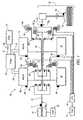
- FIG. 1is a schematic diagram of an exemplary powertrain comprising a two-mode, compound-split, electro-mechanical hybrid transmission operatively connected to an engine and first and second electric machines, in accordance with the present disclosure
- FIG. 2is a schematic block diagram of an exemplary distributed control module system, in accordance with the present disclosure
- FIG. 3graphically depicts reaction times of exemplary hybrid powertrain components to changes in torque request, in accordance with the present disclosure
- FIG. 4shows an exemplary control system architecture for controlling and managing torque and power flow in a powertrain system having multiple torque generative devices and residing in control modules in the form of executable algorithms and calibrations, in accordance with the present disclosure
- FIG. 5is a schematic diagram exemplifying data flow through a shift execution, describing more detail exemplary execution of the control system architecture of FIG. 4 in greater detail, in accordance with the present disclosure
- FIG. 6demonstrates gear transition relationships for an exemplary hybrid powertrain transmission, in particular as described in the exemplary embodiment of FIG. 1 and Table 1, in accordance with the present disclosure
- FIGS. 7-10depict a number of exemplary transmission shifts, in accordance with the present disclosure.
- FIG. 7demonstrates a fixed gear state to fixed gear ratio state shift
- FIG. 8demonstrates a shift similar to the shift of FIG. 7 , except that the initial operating range state is an EVT mode;
- FIG. 9demonstrates a shift similar to the shift of FIG. 8 , except that the constant rate of change of output speed assumed in FIG. 9 is negative;
- FIG. 10demonstrates a shift from a fixed gear state to an EVT mode
- FIGS. 11-13depict exemplary processes combining to accomplish an exemplary transmission shift, in accordance with the present disclosure
- FIG. 11is a graphical representation of torque terms associated with a clutch through an exemplary transitional unlocking state
- FIG. 12is a graphical representation of torque terms associated with a clutch through an exemplary transitional locking state
- FIG. 13is a graphical representation of terms describing an exemplary inertia speed phase of a transmission, in accordance with the present disclosure
- FIG. 14illustrates in tabular form use of an exemplary 2D look-up table to determine inertia speed phase times, in accordance with the present disclosure
- FIG. 15describes an exemplary inertia speed phase divided into three sub-phases, in accordance with the present disclosure
- FIG. 16is a graphical representation of an instance where a systemic restraint is imposed upon an immediate control signal, temporarily overriding max ⁇ min values set by the control signal, in accordance with the present disclosure
- FIG. 17graphically illustrates an exemplary inertia speed phase wherein an input acceleration immediate profile is affected by imposition of a maximum input acceleration constraint in accordance with the present disclosure
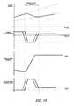
- FIG. 18graphically illustrates simultaneous measurement of input speed input, input acceleration, slip speed, and slip acceleration through an exemplary inertia speed phase unaffected by an input acceleration constraint, according to the present disclosure.
- FIGS. 1 and 2depict an exemplary electro-mechanical hybrid powertrain.
- the exemplary electro-mechanical hybrid powertrain in accordance with the present disclosureis depicted in FIG. 1 , comprising a two-mode, compound-split, electro-mechanical hybrid transmission 10 operatively connected to an engine 14 and first and second electric machines ('MG-A') 56 and ('MG-B') 72.
- the engine 14 and first and second electric machines 56 and 72each generate power which can be transmitted to the transmission 10.
- the power generated by the engine 14 and the first and second electric machines 56 and 72 and transmitted to the transmission 10is described in terms of input torques, referred to herein as T I , T A , and T B respectively, and speed, referred to herein as N I , N A , and N B , respectively.
- the exemplary engine 14comprises a multi-cylinder internal combustion engine selectively operative in several states to transmit torque to the transmission 10 via an input shaft 12, and can be either a spark-ignition or a compression-ignition engine.
- the engine 14includes a crankshaft (not shown) operatively coupled to the input shaft 12 of the transmission 10.
- a rotational speed sensor 11monitors rotational speed of the input shaft 12.
- Power output from the engine 14, comprising rotational speed and output torquecan differ from the input speed, N I , and the input torque, T I , to the transmission 10 due to placement of torque-consuming components on the input shaft 12 between the engine 14 and the transmission 10, e.g., a hydraulic pump (not shown) and/or a torque management device (not shown).
- the exemplary transmission 10comprises three planetary-gear sets 24, 26 and 28, and four selectively engageable torque-transmitting devices, i.e., clutches C1 70, C2 62, C3 73, and C4 75.
- clutchesrefer to any type of friction torque transfer device including single or compound plate clutches or packs, band clutches, and brakes, for example.
- a hydraulic control circuit 42preferably controlled by a transmission control module (hereafter 'TCM') 17, is operative to control clutch states.
- Clutches C2 62 and C4 75preferably comprise hydraulically-applied rotating friction clutches.
- Clutches C1 70 and C3 73preferably comprise hydraulically-controlled stationary devices that can be selectively grounded to a transmission case 68.
- Each of the clutches C1 70, C2 62, C3 73, and C4 75is preferably hydraulically applied, selectively receiving pressurized hydraulic fluid via the hydraulic control circuit 42.
- the first and second electric machines 56 and 72preferably comprise three-phase AC machines, each including a stator (not shown) and a rotor (not shown), and respective resolvers 80 and 82.
- the motor stator for each machineis grounded to an outer portion of the transmission case 68, and includes a stator core with coiled electrical windings extending therefrom.
- the rotor for the first electric machine 56is supported on a hub plate gear that is operatively attached to shaft 60 via the second planetary gear set 26.
- the rotor for the second electric machine 72is fixedly attached to a sleeve shaft hub 66.
- Each of the resolvers 80 and 82preferably comprises a variable reluctance device including a resolver stator (not shown) and a resolver rotor (not shown).
- the resolvers 80 and 82are appropriately positioned and assembled on respective ones of the first and second electric machines 56 and 72.
- Stators of respective ones of the resolvers 80 and 82are operatively connected to one of the stators for the first and second electric machines 56 and 72.
- the resolver rotorsare operatively connected to the rotor for the corresponding first and second electric machines 56 and 72.
- Each of the resolvers 80 and 82is signally and operatively connected to a transmission power inverter control module (hereafter 'TPIM') 19, and each senses and monitors rotational position of the resolver rotor relative to the resolver stator, thus monitoring rotational position of respective ones of first and second electric machines 56 and 72. Additionally, the signals output from the resolvers 80 and 82 are interpreted to provide the rotational speeds for first and second electric machines 56 and 72, i.e., N A and N B , respectively.
- the transmission 10includes an output member 64, e.g. a shaft, which is operably connected to a driveline 90 for a vehicle (not shown), to provide output power, e.g., to vehicle wheels 93, one of which is shown in FIG. 1 .
- the output poweris characterized in terms of an output rotational speed, N O and an output torque, T O .
- a transmission output speed sensor 84monitors rotational speed and rotational direction of the output member 64.
- Each of the vehicle wheels 93is preferably equipped with a sensor 94 adapted to monitor wheel speed, V SS-WHL , the output of which is monitored by a control module of a distributed control module system described with respect to FIG. 8 , to determine vehicle speed, and absolute and relative wheel speeds for braking control, traction control, and vehicle acceleration management.
- the input torques from the engine 14 and the first and second electric machines 56 and 72(T I , T A , and T B respectively) are generated as a result of energy conversion from fuel or electrical potential stored in an electrical energy storage device (hereafter ⁇ ESD') 74.
- the ESD 74is high voltage DC-coupled to the TPIM 19 via DC transfer conductors 27.
- the transfer conductors 27include a contactor switch 38. When the contactor switch 38 is closed, under normal operation, electric current can flow between the ESD 74 and the TPIM 19. When the contactor switch 38 is opened electric current flow between the ESD 74 and the TPIM 19 is interrupted.
- the TPIM 19transmits electrical power to and from the first electric machine 56 by transfer conductors 29, and the TPIM 19 similarly transmits electrical power to and from the second electric machine 72 by transfer conductors 31, in response to torque requests to the first and second electric machines 56 and 72 to achieve the input torques T A and T B . Electrical current is transmitted to and from the ESD 74 in accordance with whether the ESD 74 is being charged or discharged.
- the TPIM 19includes the pair of power inverters (not shown) and respective motor control modules (not shown) configured to receive the torque commands and control inverter states therefrom for providing motor drive or regeneration functionality to meet the commanded motor torques T A and T B .
- the power inverterscomprise known complementary three-phase power electronics devices, and each includes a plurality of insulated gate bipolar transistors (not shown) for converting DC power from the ESD 74 to AC power for powering respective ones of the first and second electric machines 56 and 72, by switching at high frequencies.
- the insulated gate bipolar transistorsform a switch mode power supply configured to receive control commands. There is typically one pair of insulated gate bipolar transistors for each phase of each of the three-phase electric machines.
- the three-phase invertersreceive or supply DC electric power via DC transfer conductors 27 and transform it to or from three-phase AC power, which is conducted to or from the first and second electric machines 56 and 72 for operation as motors or generators via transfer conductors 29 and 31 respectively.
- FIG. 2is a schematic block diagram of the distributed control module system.
- the elements described hereinaftercomprise a subset of an overall vehicle control architecture, and provide coordinated system control of the exemplary powertrain described in FIG. 1 .
- the distributed control module systemsynthesizes pertinent information and inputs, and executes algorithms to control various actuators to achieve control objectives, including objectives related to fuel economy, emissions, performance, drivability, and protection of hardware, including batteries of ESD 74 and the first and second electric machines 56 and 72.
- the distributed control module systemincludes an engine control module (hereafter 'ECM') 23, the TCM 17, a battery pack control module (hereafter 'BPCM') 21, and the TPIM 19.
- 'ECM'engine control module
- TCM 17battery pack control module
- TPIM 19battery pack control module
- a hybrid control module (hereafter 'HCP') 5provides supervisory control and coordination of the ECM 23, the TCM 17, the BPCM 21, and the TPIM 19.
- a user interface ('UI') 13is operatively connected to a plurality of devices through which a vehicle operator controls or directs operation of the electro-mechanical hybrid powertrain.
- the devicesinclude an accelerator pedal 113 ('AP') from which an operator torque request is determined, an operator brake pedal 112 ('BP'), a transmission gear selector 114 ('PRNDL'), and a vehicle speed cruise control (not shown).
- the transmission gear selector 114may have a discrete number of operator-selectable positions, including the rotational direction of the output member 64 to enable one of a forward and a reverse direction.
- the aforementioned control modulescommunicate with other control modules, sensors, and actuators via a local area network (hereafter 'LAN') bus 6.
- the LAN bus 6allows for structured communication of states of operating parameters and actuator command signals between the various control modules.
- the specific communication protocol utilizedis application-specific.
- the LAN bus 6 and appropriate protocolsprovide for robust messaging and multi-control module interfacing between the aforementioned control modules, and other control modules providing functionality such as antilock braking, traction control, and vehicle stability.
- Multiple communications busesmay be used to improve communications speed and provide some level of signal redundancy and integrity. Communication between individual control modules can also be effected using a direct link, e.g., a serial peripheral interface ('SPI') bus (not shown).
- 'SPI'serial peripheral interface
- the HCP 5provides supervisory control of the powertrain, serving to coordinate operation of the ECM 23, TCM 17, TPIM 19, and BPCM 21. Based upon various input signals from the user interface 13 and the powertrain, including the ESD 74, the HCP 5 generates various commands, including: the operator torque request ('T O_REQ '), a commanded output torque ('T CMD ') to the driveline 90, an engine input torque request, clutch torques for the torque-transfer clutches C1 70, C2 62, C3 73, C4 75 of the transmission 10; and the torque requests for the first and second electric machines 56 and 72, respectively.
- the TCM 17is operatively connected to the hydraulic control circuit 42 and provides various functions including monitoring various pressure sensing devices (not shown) and generating and communicating control signals to various solenoids (not shown) thereby controlling pressure switches and control valves contained within the hydraulic control circuit 42.
- the ECM 23is operatively connected to the engine 14, and functions to acquire data from sensors and control actuators of the engine 14 over a plurality of discrete lines, shown for simplicity as an aggregate bi-directional interface cable 35.
- the ECM 23receives the engine input torque request from the HCP 5.
- the ECM 23determines the actual engine input torque, T I , provided to the transmission 10 at that point in time based upon monitored engine speed and load, which is communicated to the HCP 5.
- the ECM 23monitors input from the rotational speed sensor 11 to determine the engine input speed to the input shaft 12, which translates to the transmission input speed, N I .
- the ECM 23monitors inputs from sensors (not shown) to determine states of other engine operating parameters including, e.g., a manifold pressure, engine coolant temperature, ambient air temperature, and ambient pressure.
- the engine loadcan be determined, for example, from the manifold pressure, or alternatively, from monitoring operator input to the accelerator pedal 113.
- the ECM 23generates and communicates command signals to control engine actuators, including, e.g., fuel injectors, ignition modules, and throttle control modules, none of which are shown.
- the TCM 17is operatively connected to the transmission 10 and monitors inputs from sensors (not shown) to determine states of transmission operating parameters.
- the TCM 17generates and communicates command signals to control the transmission 10, including controlling the hydraulic control circuit 42.
- Inputs from the TCM 17 to the HCP 5include estimated clutch torques for each of the clutches, i.e., C1 70, C2 62, C3 73, and C4 75, and rotational output speed, No, of the output member 64.
- Other actuators and sensorsmay be used to provide additional information from the TCM 17 to the HCP 5 for control purposes.
- the TCM 17monitors inputs from pressure switches (not shown) and selectively actuates pressure control solenoids (not shown) and shift solenoids (not shown) of the hydraulic control circuit 42 to selectively actuate the various clutches C1 70, C2 62, C3 73, and C4 75 to achieve various transmission operating range states, as described hereinbelow.
- the BPCM 21is signally connected to sensors (not shown) to monitor the ESD 74, including states of electrical current and voltage parameters, to provide information indicative of parametric states of the batteries of the ESD 74 to the HCP 5.
- the parametric states of the batteriespreferably include battery state-of-charge, battery voltage, battery temperature, and available battery power, referred to as a range P BAT_MIN to P BAT_MAX .
- Each of the control modules ECM 23, TCM 17, TPIM 19 and BPCM 21is preferably a general-purpose digital computer comprising a microprocessor or central processing unit, storage mediums comprising read only memory ('ROM'), random access memory ('RAM'), electrically programmable read only memory ('EPROM'), a high speed clock, analog to digital ('A/D') and digital to analog ('D/A') circuitry, and input/output circuitry and devices ('I/O') and appropriate signal conditioning and buffer circuitry.
- Each of the control moduleshas a set of control algorithms, comprising resident program instructions and calibrations stored in one of the storage mediums and executed to provide the respective functions of each computer.
- control algorithmsare executed during preset loop cycles such that each algorithm is executed at least once each loop cycle.
- Algorithms stored in the non-volatile memory devicesare executed by one of the central processing units to monitor inputs from the sensing devices and execute control and diagnostic routines to control operation of the actuators, using preset calibrations.
- Loop cyclesare executed at regular intervals, for example each 3.125, 6.25, 12.5, 25 and 100 milliseconds during ongoing operation of the powertrain. Alternatively, algorithms may be executed in response to the occurrence of an event.
- the exemplary powertrainselectively operates in one of several operating range states that can be described in terms of an engine state comprising one of an engine on state ('ON') and an engine off state ('OFF'), and a transmission state comprising a plurality of fixed gears and continuously variable operating modes, described with reference to Table 1, below.
- Each of the transmission operating range statesis described in the table and indicates which of the specific clutches C1 70, C2 62, C3 73, and C4 75 are applied for each of the operating range states.
- a first continuously variable modei.e., EVT Mode I, or MI
- the engine statecan be one of ON ('MI_Eng_On') or OFF ('MI_Eng_Off').
- a second continuously variable modei.e., EVT Mode II, or MII, is selected by applying clutch C2 62 only to connect the shaft 60 to the carrier of the third planetary gear set 28.
- the engine statecan be one of ON ('MII_Eng_On') or OFF ('MII_Eng_Off').
- 'RPM'revolutions per minute
- a fixed gear operationprovides a fixed ratio operation of input-to-output speed of the transmission 10, i.e., N I /N O , is achieved.
- a first fixed gear operation('FG1') is selected by applying clutches C1 70 and C4 75.
- a second fixed gear operation ( ⁇ FG2')is selected by applying clutches C1 70 and C2 62.
- a third fixed gear operation( ⁇ FG3') is selected by applying clutches C2 62 and C4 75.
- a fourth fixed gear operation ('FG4')is selected by applying clutches C2 62 and C3 73.
- the fixed ratio operation of input-to-output speedincreases with increased fixed gear operation due to decreased gear ratios in the planetary gears 24, 26, and 28.
- the rotational speeds of the first and second electric machines 56 and 72, N A and N B respectively,are dependent on internal rotation of the mechanism as defined by the clutching and are proportional to the input speed measured at the input shaft 12.
- the HCP 5 and one or more of the other control modulesdetermine the commanded output torque, T CMD , intended to meet the operator torque request, T O_REQ , to be executed at the output member 64 and transmitted to the driveline 90.
- Final vehicle accelerationis affected by other factors including, e.g., road load, road grade, and vehicle mass.
- the operating range stateis determined for the transmission 10 based upon a variety of operating characteristics of the powertrain. This includes the operator torque request, communicated through the accelerator pedal 113 and brake pedal 112 to the user interface 13 as previously described.
- the operating range statemay be predicated on a powertrain torque demand caused by a command to operate the first and second electric machines 56 and 72 in an electrical energy generating mode or in a torque generating mode.
- the operating range statecan be determined by an optimization algorithm or routine, initiated for example within a hybrid strategic control module of the HCP 5, which determines optimum system efficiency based upon operator demand for power, battery state of charge, and energy efficiencies of the engine 14 and the first and second electric machines 56 and 72.
- the control systemmanages torque inputs from the engine 14 and the first and second electric machines 56 and 72 based upon an outcome of the executed optimization routine, and system efficiencies are optimized thereby, to manage fuel economy and battery charging. Furthermore, operation can be determined based upon a fault in a component or system.
- the HCP 5monitors the torque-generative devices, and determines the power output from the transmission 10 required to achieve the desired output torque to meet the operator torque request.
- the ESD 74 and the first and second electric machines 56 and 72are electrically-operatively coupled for power flow therebetween.
- the engine 14, the first and second electric machines 56 and 72, and the electro-mechanical transmission 10are mechanically-operatively coupled to transmit power therebetween to generate a power flow to the output member 64.
- managing output torque in order to maintain drivabilityis a priority in controlling a hybrid powertrain. Any change in torque in response to a change in output torque request applied through the transmission results in a change to the output torque applied to the driveline, thereby resulting in a change in propelling force to the vehicle and a change in vehicle acceleration.
- the change in torque requestcan come from operator input, such a pedal position relating an operator torque request, automatic control changes in the vehicle, such as cruise control or other control strategy, or engine changes in response to environmental conditions, such as a vehicle experiencing an uphill or downhill grade.
- any control systemincludes a reaction time. Changes to a powertrain operating point, comprising the speeds and torques of the various components to the powertrain required to achieve the desired vehicle operation, are driven by changes in control signals. These control signal changes act upon the various components to the powertrain and create reactions in each according to their respective reaction times. Applied to a hybrid powertrain, any change in control signals indicating a new torque request, for instance, as driven by a change in operator torque request or as required to execute a transmission shift, creates reactions in each affected torque generating device in order to execute the required changes to respective input torques. Changes to input torque supplied from an engine are controlled by an engine torque request setting the torque generated by the engine, as controlled, for example, through an ECM.
- Reaction time within an engine to changes in torque request to an engineis impacted by a number of factors well known in the art, and the particulars of a change to engine operation depend heavily on the particulars of the engine employed and the mode or modes of combustion being utilized. In many circumstances, the reaction time of an engine to changes in torque request will be the longest reaction time of the components to the hybrid powertrain. Reaction time within an electric machine to changes in torque request include time to activate any necessary switches, relays, or other controls and time to energize or de-energize the electric machine with the change in applied electrical power.
- FIG. 3graphically depicts reaction times of exemplary hybrid powertrain components to changes in torque request, in accordance with the present disclosure.
- Components to an exemplary hybrid powertrain system including an engine and two electric machinesare exemplified. Torque requests and resulting changes in input torque produced by each torque generating device are illustrated. As described above, the data shows that electric machines quickly respond to changes in torque requests, whereas the engine follows changes in torque requests more slowly.
- a methodis disclosed wherein reactions times of the engine and of the electric machine or machines within a hybrid powertrain are utilized to control in parallel an immediate lead torque request, controlling the engine, and an immediate torque request, controlling the electric machines, the torque requests being coordinated by respective reaction times in order to substantially effect simultaneous changes to input torque.
- an exemplary embodiment of the disclosed methodcan implement changes in torque request to the engine and the electric machine, acting in parallel as described above, including a lead period to the more quickly reacting device, the electric motor.
- This lead periodmay be developed experimentally, empirically, predictively, through modeling or other techniques adequate to accurately predict engine and electric machine operation, and a multitude of lead periods might be used by the same hybrid powertrain, depending upon different engine settings, conditions, operating and ranges and vehicle conditions.
- An exemplary equation that can be used in conjunction with test data or estimates of device reaction times to calculate lead period in accordance with the present disclosureincludes the following equation.
- T LeadR Lead Reaction - T Immediate Reaction
- T Leadequals the lead period for use in methods described herein. This equation assumes that two torque producing devices are utilized. T Lead Reaction represents the reaction time of the device with the longer reaction time, and T Immediate Reaction represents the reaction time of the device with the shorter reaction time. If a different system is utilized, comprising for example, an engine with a long lead period, a first electric machine with an intermediate lead period, and a second electric machine with a short lead period, lead periods can be developed comparing all of the torque generating devices. In this exemplary system, if all three torque generating devices are involved, two lead periods, one for the engine as compared to each of the electric machines, will be utilized to synchronize the responses in each of the devices.
- the same system at a different timemight be operating with the engine off and disengaged from the transmission, and a lead period comparing the first electric machine and the second electric machine will be utilized to synchronize the responses in the two electric machines. In this way, a lead period can be developed coordinating reaction times between various torque generating devices can be developed.
- One exemplary method to utilize lead periods to implement parallel commands to distinct torque generating devices in order to effect substantially simultaneous changes to output torque in response to a change in operator torque requestincludes issuing substantially immediately a change to the engine commands, initiating within the engine a change to a new engine output torque.
- This new engine output torquein conjunction with the electric motor operating state, is still managed by the HCP in order to provide some portion of the total input torque to the transmission required to propel the vehicle. From the point that the engine commands change, the lead period begins to run, described above taking into account the differences in reaction times between the engine and the electric machine.
- Shifts within a transmissionfrequently involve unloading a first clutch, transitioning through an inertia speed phase state, and subsequently loading a second clutch.
- the change within a transmission from one fixed gear state to another fixed gear statefrequently includes unloading a first clutch, allowing the vehicle to briefly coast, and then loading a second clutch.
- clutches within a hybrid powertrain transmissionare frequently applied in pairs or groups, and a shift within the transmission can involve only unloading one of the applied clutches and subsequently loading another clutch while maintaining engagement of a third clutch throughout the shift.
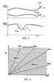
- N Iis plotted against No.
- Nois determined by the corresponding N I along the fixed gear state plots.
- Operation in either EVT Mode I or EVT Mode II, wherein a continuously variable gear ratio is utilized to power from a fixed input speedcan take place in the respective zones illustrated on the graph.
- Clutch states, C1 - C4, as described in the exemplary embodiment of FIG. 1are described in Table 1. For instance, operation in a second fixed gear state requires clutches C1 and C2 to be applied or loaded and clutches C3 and C4 to be not applied or unloaded. While FIG.
- FIG. 4can describe operation of an exemplary system in a fixed gear state or EVT mode, as described above, and it can also be used to describe shift transitions between the various transmission operating range states.
- the areas and plots on the graphdescribe operation of the operating range states through transitions. For example, transitions between fixed gear states within an EVT mode region require transitory operation in the EVT mode between the fixed gear states. Similarly, transition from EVT Mode I to EVT Mode II requires a transition through the second fixed gear state, located at the boundary between the two modes.
- a shift from the third fixed gear state to EVT Mode IIrequires clutch C4 to be changed from an applied to a not applied state and requires that clutch C2 remain applied.
- Table 1describes operation in the fourth fixed gear mode, the destination of the second shift, wherein clutches C2 and C3 are applied. Therefore, a shift from EVT Mode II to the fourth fixed gear state requires clutch C3 to be applied and loaded and requires that clutch C2 remain applied. Therefore, clutches C4 and C3 are transitioned through the exemplary shift, while clutch C2 remains applied and transmitting torque to the driveline throughout the shift event.
- FIG. 4shows a control system architecture for controlling and managing torque and power flow in a powertrain system having multiple torque generative devices, described hereinbelow with reference to the hybrid powertrain system shown in FIGS. 1 and 2 , and residing in the aforementioned control modules in the form of executable algorithms and calibrations.
- the control system architecturecan be applied to any powertrain system having multiple torque generative devices, including, e.g., a hybrid powertrain system having a single electric machine, a hybrid powertrain system having multiple electric machines, and non-hybrid powertrain systems.
- the control system architecture of FIG. 4depicts a flow of pertinent signals through the control modules.
- the operator inputs to the accelerator pedal 113 and the brake pedal 112are monitored to determine the operator torque request ('T O_REQ ').
- Operation of the engine 14 and the transmission 10are monitored to determine the input speed ('N I ') and the output speed ('N O ').
- a strategic optimization control scheme ('Strategic Control') 310determines a preferred input speed ('N I_DES ') and a preferred engine state and transmission operating range state ('Hybrid Range State Des') based upon the output speed and the operator torque request, and optimized based upon other operating parameters of the hybrid powertrain, including battery power limits and response limits of the engine 14, the transmission 10, and the first and second electric machines 56 and 72.
- the strategic optimization control scheme 310is preferably executed by the HCP 5 during each 100 ms loop cycle and each 25 ms loop cycle.
- the outputs of the strategic optimization control scheme 310are used in a shift execution and engine start/stop control scheme ('Shift Execution and Engine Start/Stop') 320 to command changes in the transmission operation ('Transmission Commands') including changing the operating range state.
- the present operating range state ('Hybrid Range State Actual') and an input speed profile ('N I_PROF ')can be determined.
- the input speed profileis an estimate of an upcoming input speed and preferably comprises a scalar parametric value that is a targeted input speed for the forthcoming loop cycle.
- the engine operating commands and the operator torque requestare based upon the input speed profile during a transition in the operating range state of the transmission.
- a tactical control scheme ('Tactical Control and Operation') 330is repeatedly executed during one of the control loop cycles to determine engine commands ('Engine Commands') for operating the engine, including a preferred input torque from the engine 14 to the transmission 10 based upon the output speed, the input speed, and the operator torque request and the present operating range state for the transmission.
- the engine commandsalso include engine states including one of an all-cylinder operating state and a cylinder deactivation operating state wherein a portion of the engine cylinders are deactivated and unfueled, and engine states including one of a fueled state and a fuel cutoff state.
- a clutch torque ('T CL ') for each clutchis estimated in the TCM 17, including the presently applied clutches and the non-applied clutches, and a present engine input torque ('T I ') reacting with the input member 12 is determined in the ECM 23.
- a motor torque control scheme ('Output and Motor Torque Determination') 340is executed to determine the preferred output torque from the powertrain ('T O_CMD '), which includes motor torque commands ('T A ', 'T B ') for controlling the first and second electric machines 56 and 72 in this embodiment.
- the preferred output torqueis based upon the estimated clutch torque(s) for each of the clutches, the present input torque from the engine 14, the present operating range state, the input speed, the operator torque request, and the input speed profile.
- the first and second electric machines 56 and 72are controlled through the TPIM 19 to meet the preferred motor torque commands based upon the preferred output torque.
- the motor torque control scheme 340includes algorithmic code which is regularly executed during the 6.25 ms and 12.5 ms loop cycles to determine the preferred motor torque commands.
- FIG. 5is a schematic diagram exemplifying data flow through a shift execution, describing more detail exemplary execution of the control system architecture such as the system of FIG. 4 in greater detail, in accordance with the present disclosure.
- Powertrain control system 400is illustrated comprising several hybrid drive components, including an engine 410, an electric machine 420, and clutch hydraulics 430.
- Control modules strategic control module 310, shift execution module 450, clutch capacity control module 460, tactical control and operation module 330, output and motor torque determination module 340, and clutch control module 490,are illustrated, processing information and issuing control commands to engine 410, electric machine 420, and clutch hydraulics 430.
- control modulescan be physically separate, can be grouped together in a number of different control devices, or can be entirely performed within a single physical control device.
- Module 310a strategic control module, performs determinations regarding preferred powertrain operating points and preferred operating range states as described in FIG. 4 .
- Module 450a shift execution module, receives input from strategic control module 310 and other sources regarding shift initiation. Module 450 processes inputs regarding the reactive torque currently applied to the clutch and the preferred operating range state to be transitioned to.
- Module 450then employs programming, determining parameters for the execution of the shift, including hybrid range state parameters describing the balance of input torques required of the torque providing devices, details regarding a target input speed and input acceleration lead predicted required to execute the transition to the preferred operating range state, an input acceleration lead immediate as previously described, and clutch reactive torque lead immediate min/max and clutch reactive torque immediate min/max values as previously described.
- clutch reactive torque parameters and hybrid range state informationare fed to clutch capacity control module 460, lead control parameters and signals are fed to tactical control and operation module 330, and immediate control parameters and signals are fed to output and motor torque determination module 340.
- Clutch capacity control module 460processes reactive torque and hybrid range state information and generates logic describing clutch reactive torque limits enabling engine control through module 330, electric machine control through module 340, and clutch control through module 490, in accordance with methods described herein.
- Tactical control and operation module 330includes means to issue torque requests and execute limits upon input torque supplied from engine 410, and feed, additionally, describe the input torque supplied from the engine to module 340 for use in control of electric machine 420.
- Output and motor torque determination module 340likewise receives and processes information to issue electric machine torque requests to electric machine 420. Additionally, module 340 generates clutch reactive torque commands for use by clutch control module 490.
- Module 490processes information from module 340 and issues hydraulic commands in order to achieve the required clutch torque capacity required to operate the transmission.
- This particular embodiment of data flowillustrates one possible exemplary process by which a vehicular torque generative devices and related clutches can be controlled in accordance with the method disclosed herein. It will be appreciated by one having ordinary skill in the art that the particular process employed can vary, and this disclosure is not intended to limited to the particular exemplary embodiment described herein.
- engine commands and electric machine commandsare disclosed for use in parallel to control distinct torque generative devices with different reaction times to reaction to changes in operator torque request.
- Changes in operator torque requestcan include a simple change in desired output torque within a particular transmission operating range state, or changes in operator torque request can be required in conjunction with a transmission shift between different operating range states.
- Changes to operator torque requests in conjunction with a transmission shiftare more complex than changes contained within a single operating range state because torques and shaft speeds of the various hybrid powertrain components must be managed in order to transition torque applied from a first clutch and to a second previously not applied clutch without the occurrence of slip, as described above.
- Shifts within a transmissionfrequently involve unloading a first clutch, transitioning through an inertia speed phase state, and subsequently loading a second clutch.
- the change within a transmission from one fixed gear state to another fixed gear stateusually includes unloading a first clutch, allowing the vehicle to briefly coast, and then loading a second clutch.
- clutches within a hybrid powertrain transmissionare frequently applied in pairs or groups, and a shift within the transmission can involve only unloading one of the applied clutches and subsequently loading another clutch while maintaining engagement of a third clutch throughout the shift.
- N Iis plotted against N O .
- Nois determined by the corresponding N I along the fixed gear state plots.
- Operation in either EVT Mode I or EVT Mode II, wherein a continuously variable gear ratio is utilized to power from a fixed input speedcan take place in the respective zones illustrated on the graph.
- Clutch states, C1 - C4, as described in the exemplary embodiment of FIG. 1are described in Table 1. For instance, operation in a second fixed gear state requires clutches C1 and C2 to be applied or loaded and clutches C3 and C4 to be not applied or unloaded. While FIG.
- FIG. 6can describe operation of an exemplary system in a fixed gear state or EVT mode, as described above, and it can also be used to describe shift transitions between the various transmission operating range states.
- the areas and plots on the graphdescribe operation of the operating range states through transitions. For example, transitions between fixed gear states within an EVT mode region require transitory operation in the EVT mode between the fixed gear states. Similarly, transition from EVT Mode I to EVT Mode II requires a transition through the second fixed gear state, located at the boundary between the two modes.
- a shift from the third fixed gear state to EVT Mode IIrequires clutch C4 to be changed from an applied to a not applied state and requires that clutch C2 remain applied.
- Table 1describes operation in the fourth fixed gear mode, the destination of the second shift, wherein clutches C2 and C3 are applied. Therefore, a shift from EVT Mode II to the fourth fixed gear state requires clutch C3 to be applied and loaded and requires that clutch C2 remain applied. Therefore, clutches C4 and C3 are transitioned through the exemplary shift, while clutch C2 remains applied and transmitting torque to the driveline throughout the shift event.
- Transmission shifts in a multi-clutch transmissioncan be broken down into phases: torque phases include periods wherein selected clutches are locked and torque is being applied or transitioned through degrees of application through the locked clutches; and an inertia speed phases wherein a disengaged clutch is in the process of being synchronized for pending application.
- Shiftscan be defined by the initial and destination operating range states of the shift.
- fixed gear range statesinvolve a fixed gear ratio between the input speed and the output speed. In the exemplary transmission of FIG. 1 , this translates to two clutches in an engaged mode.
- a constant rate of change in output speed, depicted against time on a graph,will show a fixed gear state as a sloped line, with the slope indicating the rate of change in output speed and the gear ratio.
- EVT mode range statesinvolve a transmission setting wherein input speed and output speed are independent of each other.
- the input speedis usually operated at some calibrated optimal input speed for the range of operation in that EVT mode, and the planetary gear sets in the transmission are manipulated to vary the speed of the output.
- a constant rate of change in output speedwill have no effect on the input speed operated at a constant speed, and a depicted against time on a graph, EVT modes will show a horizontal line. Shifts between operating range states on a graph preferably assume constant acceleration of output speed, either positive or negative, through a time period and show transitions from one operating range state to another.
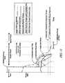
- FIGS. 7-10depict a number of exemplary transmission shifts, in accordance with the present disclosure. All four figures assume a constant acceleration of the output speed, although the rate can be different between figures.
- FIG. 7demonstrates a fixed gear state to fixed gear ratio state shift. Two dotted lines are depicted, representing input speeds possible under fixed gear operation assuming a constantly increasing output speed through a time period.
- the input speed immediate profiledescribes input speed changing through an inertia speed phase from an initial input speed to an input speed required to synchronously shift into the destination operating range state. Once the input speed reaches the target input speed, the synchronized clutch can lock, and torque can be transferred to the clutch through a torque phase.
- FIG. 8demonstrates a shift similar to the shift of FIG.
- FIG. 7except that the initial operating range state is an EVT mode.
- an inertia speed phaseis initiated in FIG. 8 , wherein the input speed changes from an initial input speed to an input speed required to synchronously shift into the destination operating range state.
- FIG. 9demonstrates a shift similar to the shift of FIG. 8 , except that the constant rate of change of output speed assumed in FIG. 9 is negative.
- the operating range stateis initially an EVT mode, and upon initiation of a shift to a fixed gear state, an inertia speed phase is initiated wherein the input speed changes from an initial input speed to an input speed required to synchronously shift into the destination operating range state.
- FIG. 10demonstrates a shift from a fixed gear state to an EVT mode.
- a shift to EVT modewherein the transmission changes from two locked clutches to one, has a unique property in that no inertia speed phase is required.
- the remaining locked clutchdefines operation in the destination EVT mode. No synchronization is required, and the input speed is free to transition to the calibrated optimal input speed programmed for operation in the EVT mode.
- FIGS. 11-13depict exemplary processes combining to accomplish an exemplary transmission shift, in accordance with the present disclosure.
- FIG. 11is a graphical representation of torque terms associated with a clutch through an exemplary transitional unlocking state, in accordance with the present disclosure.
- Lines illustrated at the left extreme of the graphdepict clutch operation in a locked state.
- the graphdepicts clutch command torque by a clutch control system and a resulting estimated torque capacity.
- Clutch torque capacity in a clutch resulting from a command torqueis a result of many factors, including available clamping pressure, design and conditional factors of the clutch, reaction time in the clutch to changes in the clutch control system.
- itis known to command a torque to a locked clutch in excess of the clutch achievable capacity and allow the other factors affecting the clutch to determine the resulting clutch capacity.
- the clutchreacts to a change in command torque over a reaction time, and reaction time for a particular clutch will depend upon the particulars of the application.
- torque capacityreacts to a reduction in command torque and begins to reduce accordingly.
- FIG. 11illustrates a method to perform this coordinated change to torque requests by imposing limits upon torque requests in the form of a clutch reactive torque immediate lead minimum and maximum constraining the engine torque immediate request and a clutch reactive torque immediate minimum and maximum constraining the torque request to the electric machine.
- maximum reactive torque valuesrepresent the maximum torque that is permitted to be commanded from each torque providing device: the actual engine torque immediate request and the actual immediate torque request can be less than the maximum reactive torque values, but as the maximum values reduce, so the actual torque request values will also eventually reduce.
- the input torques from the engine and electric machinetogether provide, each up to the defined maximum values, some portion of the overall input torques, with the portion of each being controlled by the HCP.
- both the clutch reactive torque immediate lead minimum and maximum and the clutch reactive torque immediate minimum and maximumapplied reactive torque to the clutch at substantially the same time, resulting in the reduction to the actual clutch reactive torque as illustrated in FIG. 11 .
- a calibrated threshold for torque estimatecan be used to define the end of the torque phase. For instance, if an estimate of the clutch torque capacity, as determined by an algorithm modeling clutch operation, stays below this threshold through a calibrated period of time, then the clutch can be determined to be in an unlocked state.
- FIG. 12is a graphical representation of torque terms associated with a clutch through an exemplary transitional locking state, in accordance with the present disclosure.
- a second clutchis synchronized and locked, and reactive torque is transferred through the clutch.
- Lines illustrated at the left extreme of the graphdepict clutch operation in an unlocked state.
- the initiation of locking staterequires a series of subordinate commands necessary to transition the clutch from an unlocked state to a locked state.
- the clutchincluding the shaft connected to the on-coming torque providing shafts and the shaft connected to the output member, must be synchronized.
- clutch connective surfaces attached to these shaftshave been attenuated and are moving at the same rotational velocity, clamping force can begin to be applied to the clutch to bring the clutch to a locked state and begin increasing the torque capacity of the clutch.
- clutch capacitymust be increased before reactive torque to the clutch can be increased.
- an increase in clutch capacitycan be commanded anticipatorily to achieve an initial increase in clutch capacity coincident with the clutch reaching a locked state. Reactive torques, taking into account reaction times by utilizing a lead period by the method disclosed herein, can then be timely commanded with a short lag to follow increasing clutch torque capacity.
- An exemplary embodiment of this methodacting in reverse of the limits imposed to torque requests as described in FIG. 11 , imposes limits upon the torque requests which can be issued to the engine and to the electric machine according to a calibrated ramp rate, selected to avoid slip.
- a clutch reactive torque immediate minimum and maximum acting as a constraint upon electric machine torque requestsis increased after a calibrated lead period from the initiation of an increasing clutch reactive torque immediate lead minimum and maximum acting as a constraint upon engine torque requests.
- the HCPcan command the engine and the electric machine to fulfill a portion of the reactive torque required from the clutch, each up to the respective maximum.
- torque requests to the engine and the electric machineare coordinated in order to compensate for reaction times in order to increase input torques from each substantially simultaneously through a shift event.
- the calibrated ramp rate utilized in the above exemplary transmission shiftis a selected value which will adjust input torque levels to the desired range quickly, but also will stay below the torque capacity for the clutch so as to avoid slip.
- the ramp ratemay be developed experimentally, empirically, predictively, through modeling or other techniques adequate to accurately predict engine and electric machine operation, and a multitude of ramp rates might be used by the same hybrid powertrain, depending upon different engine settings, conditions, or operating ranges and behavior of the control system actuating the clutch torque capacity.
- the ramp rate used to decrease torques in an unlocking eventcan be but need not be an inverse of the ramp rate used to increase torques in a locking event.
- the lead period used to coordinate torquescan but need not be the same time span value utilized in both transmission transitional states and can be varied according to particular behaviors of a vehicle and its components.
- the transmissionpasses through an inertia speed phase between a first torque phase and a second torque phase.
- the originally applied, off-going, clutch and the on-coming clutch to be appliedare in an unlocked state, and the input is initially spinning with a rotational velocity that was shared between clutch members across the first clutch just prior to becoming desynchronized.
- inputs to be connected to the second clutchmust change N I to match the driveline attached through the transmission at some new gear ratio.
- shiftscan occur through an operating range state where at least one clutch is applied while another clutch is about to be transitioned to a locked state, but remains desynchronized.
- Operation of a transmission in a variable, non-fixed statesuch as exemplary EVT Mode I and EVT Mode II described above, allows for a variable ratio of input and output speeds. Therefore, utilizing one of the EVT modes as a transitory state through an inertia speed phase, N I can be transitioned from an initial speed to a target speed while maintaining transmission of T O .
- FIG. 13An exemplary method to accomplish this synchronization through an inertia speed phase of a transmission shift is graphically depicted in FIG. 13 , in accordance with the present disclosure.
- the effects of the transmission shift upon two terms descriptive of the shifting processare illustrated in two sections with a common timescale.
- the top sectiondepicts N I , initially connected through the first, initially applied clutch.
- the upper dotted linerepresents the velocity profile of N I while the first clutch is in a locked state before initiation of the shift.
- the bottom dotted linerepresents the velocity profile of N I that must be achieved to synchronize N I with the output speed of the second clutch.
- the transition between the two dotted linesrepresents the change to input speed that must take place to accomplish the shift.
- N I_DOTinput acceleration
- N I_DOTis described in this case as the input acceleration immediate profile or the acceleration profile driven with a relatively quick reaction time by an electric machine or machines, and the term closely tracks actual N I_DOT .
- the input acceleration immediate profileshows the change in the rate of speed which must be accomplished in order to transition the N I from an initial N I at the synchronous state with the first clutch to a target input speed at the synchronous state with the second clutch.
- the initial flat portiondescribes the acceleration with which the input speed is increased before the initiation of the shift, and this constant value reflects the slope of the input speed in the left portion of the top section of the FIG. 13 .
- a target N I_DOTbased upon No and the target operating range state after the shift is completed, can be termed an input acceleration predicted lead profile and describes the N I_DOT that needs to exist after the inertia speed phase is completed.
- a methodis disclosed to define an input acceleration immediate profile to effect changes in N I in accordance with a synchronous shift through an inertia speed phase.
- a profile defining N I_DOT through an inertia speed phaseis confined by a number of variables.
- an initial N I value and N I_DOT valuecan be monitored or described at the outset of the shift.
- a target N I value and N I_DOT valuecan be described based upon a desired operating range state, No, and a measure of powertrain operation, such as a pedal position. Constraints for the transition between the initial values and the target values include physical characteristics of the engine in response to engine commands and desired times to complete shifts. Changes to N I solely as a result of engine operation can span from wide-open throttle aggressively increasing N I to completely cutting output of the engine aggressively decreasing N I .
- Engine commandscan be modulated between these extreme engine commands for resulting changes to N I based upon desired shift characteristics.
- Changes to engine outputcan be accomplished traditionally through changes to throttle settings.
- throttle changesrequire large lead times, as described above, associated with the mechanical changes that occur when an engine receives changes in engine commands.
- a methodis known whereby either spark timing can be retarded or fuel injection timing can be modified to reduce engine output through a combustion cycle. While this method achieves changes to engine output more quickly than changes to throttle commands and allows for the previous output of the engine to be quickly restored, such changes reduce fuel efficiency by transferring less of the energy of combustion to work on the piston.
- Constraints for the transition between the initial values and the target valuesalso include desired times to complete shifts.
- a total desired speed phase timecan be defined based upon the context of powertrain operation, for example, as described by an accelerator pedal position. For instance, a shift with a fully depressed accelerator pedal (100% pedal) implies a desire by an operator to accomplish shifts and any associated decrease in T O as quickly as possible. A shift through a 0% pedal coast-down downshift implies that shift times can be relatively longer without adversely affecting drivability. Additionally, an initial input speed delta can be used to describe the degree of change in N I required to accomplish the desired shift.
- the initial input speed deltadescribes a difference between the input speed at the instant the inertia speed phase is initiated versus an input speed that would be required in at that instant if the powertrain were already in the desired operating range state.
- An exemplary initial input speed deltais illustrated in FIG. 13 .
- Greater initial input speed deltasimply that greater changes to N I will need to occur through the inertia speed phase, requiring either more drastic changes to engine output or greater total desired speed phase times.
- An exemplary method to set total desired speed phase time based upon accelerator pedal position and initial input speed deltaincludes use of a calibrated 2D look-up table.
- FIG. 14illustrates in tabular form use of an exemplary 2D look-up table to determine inertia speed phase times, in accordance with the present disclosure.
- Accelerator pedal position and the initial N I deltaallow projection of a change required in N I , as describe above, which, in turn, allows estimation of an inertia speed phase time.
- an estimated inertia speed phase timecan be estimated.
- Values of the initial N I delta in the look-up tablecan span positive and negative values, allowing for different calibrations according to upshifts and downshifts.
- FIG. 15describes an exemplary inertia speed phase divided into three sub-phases, in accordance with the present disclosure.
- Sub-phase 1describes a transition from the initial N I and N I_DOT values.
- a time T 1 for the sub-phase 1 or a first phasecan be calculated through the following equation.
- T 1K 1 * TotalDesiredSpeedPhaseTime
- K 1is a calibration between zero and one describing a desired behavior of N I .
- K 1can be a variable term, set by indications of the context of powertrain operation describing required properties of the shift, or K 1 can be a fixed calibrated value.
- Sub-phase 3describes a transition to the target N I and N I_DOT values.
- Sub-phase 2describes a transition between sub-phases 1 and 3.
- a time T 2 or a second phase, as the remaining portion of the total desired speed phase time to be set after T 1 and T 3 are defined,can be calculated through the following equation.
- T 2TotalDesiredSpeedPhaseTime - T 1 - T 3
- Sub-phase 2is depicted as a straight line in the exemplary data of FIG. 15 . It will be appreciated that a curved transition can be defined in the sub-phase 2 region depending upon the total desired speed phase time and the behavior of the exemplary powertrain. However, a straight line as depicted can be preferable.
- the slope of the N I curve in sub-phase 2describes the peak speed phase input acceleration that must be achieved in order to accomplish the desired inertia speed phase in the total desired speed phase time.
- an input acceleration immediate profilecan be defined to operate N I changes in an inertia speed phase.
- reaction times in engines to control commandstend to be slow relative to reaction times of other components of a powertrain.
- engine commands issued to an engine simultaneously to an input acceleration immediate profilewould include a resulting lag in changes to N I .
- a methodis additionally disclosed, wherein an input acceleration lead immediate profile is defined based upon a lead period describing the reaction time of the engine.
- Such a lead periodcan be the same lead period as calculated in equation (1) above or can be calculated separately based upon the specific behavior of the engine in an inertia speed phase.
- the lead period for the input acceleration lead immediate profilecan include a factor for an electric machine helping to change N I_DOT more quickly than the engine could in isolation.
- the input acceleration lead immediate profile depicted in FIG. 13includes a portion of the lead profile before the start of the inertia speed phase.
- the time period during the unlocking eventprovides a period wherein commands can be issued to the engine in advance of a desired change in N I .
- This lead in advance of the inertia speed phaseis beneficial in maintaining inertia speed phases to a total desired speed phase time, in accordance with the determinations described above.
- an adjustmentcan be made to the inertia speed phase to compensate for the reaction time of the engine and the resulting lag in changes to N I .
- Circumstances where no lead is possibleincludes a shift starting from an exemplary EVT mode, wherein only one clutch is initially engaged, and the inertia speed phase can start immediately upon command. In such a circumstance, the initiation of the inertia speed phase can be delayed after commands are issued to the engine in accordance with the determined lead time.
- FIG. 16graphically illustrates an exemplary inertia speed phase wherein an input acceleration immediate profile is affected by imposition of a minimum input acceleration constraint in accordance with the present disclosure.
- an instanceis depicted in which an input acceleration lead immediate profile has been determined for engine control through an inertia speed phase, and additionally, a corresponding input acceleration immediate profile has been determined for electric machine control through the inertia speed phase.
- Two sectionsare depicted in FIG. 16 , including a top section depicting input speed against time and a bottom section depicting input acceleration against time, with the two sections sharing a common timescale.
- negative N I_DOT or decelerationis occurring to the engine in an inertia speed phase, this condition is most commonly an instance where the engine is simply being allowed to slow down by internal frictional and pumping forces within the engine.
- FIG. 16imposes such a systemic constraint in the minimum input acceleration constraint.
- the effect of this constraint upon input speedcan be seen in the top section of the graph, wherein the straight section in the middle of the inertia speed phase is interrupted with a flattened section. Where such a constraint interferes with the input acceleration immediate, programming within the electric machine control system modify the input acceleration immediate to accommodate the constraint.
- the input acceleration immediate profileis impacted by the minimum input acceleration constraint such that negative acceleration of the input speed is delayed. Once the constraint no longer limits electric machine operation within the input acceleration immediate, the control system operates to recover the N I_DOT to the effect the desired changes to N I .
- FIG. 17graphically illustrates an exemplary inertia speed phase wherein an input acceleration immediate profile is affected by imposition of a maximum input acceleration constraint in accordance with the present disclosure.
- Two sectionsare depicted in FIG. 17 , including a top section depicting input speed against time and a bottom section depicting input acceleration against time, with the two sections sharing a common timescale.
- FIG. 17is similar to FIG. 16 , except that in FIG. 17 , an opposite constraint is imposed, wherein acceleration of the input must occur at least below the imposed maximum level.
- Reprofilingincludes making calculations required to resume an input acceleration immediate profile that will approach and attenuate input speed to a recalculated target input speed.
- the recalculated target input speedmust take into account that any effects of constraints placed upon input acceleration change a time at which the target speed will be attained, and based upon an assumed rate of change in the output speed, a different time of synchronization will create a different target input speed.
- Recalculated target input speeds in the graphs contained hereinare based upon an assumption of a constantly changing output speed for the sake of demonstrating sample calculations. However, it will be appreciated that output speed can be changing according to any number of patterns through the shift.
- reprofilingcan take many forms. Reprofiling can be as simple as reapplying a portion of the equations initially utilized to create the initial input acceleration profiles. Reprofiling taking place before T3 can include modulating the duration of the T2 and allowing T3 to complete attenuation to the recalculated target speed.
- any change in an input acceleration immediate profile to a destination fixed gear statehas the potential to impact the target speed that must be achieved in order to achieve a synchronous clutch condition.
- Tracking this moving target speed and accuracy of commanding the input speed to a newly projected target speed, a target speed that can adjust based upon the recovery profile creating a dependent loop condition in the recoverycan complicate recovery from imposition of an input acceleration constraint.
- achieving a synchronous condition in the clutchoccurs when clutch slip speed equals zero.
- FIG. 18graphically illustrates simultaneous measurement of input speed input, input acceleration, slip speed, and slip acceleration through an exemplary inertia speed phase unaffected by an input acceleration constraint, according to the present disclosure.
- Input speed and input acceleration in this graphdepict operation as described in the exemplary shift depicted in FIG. 7 .
- the third section of the graph, depicting slip speed,describes the difference in rotational speeds of the members across the clutch through the shift event.
- the slip speedis high, indicating that the members are desynchronized.
- the speeds of the clutch membersare synchronized, as described in methods above, by changing the input speed to create a zero slip or synchronous condition.
- Clutch accelerationdescribing the rate of change to clutch slip required to achieve the synchronous condition, is depicted in the bottom section of the graph. If profiling powertrain operation to achieve a synchronous condition is switched to the slip speed domain, then a similar S-shaped profile in slip speed can be commanded through a slip acceleration immediate profile similar to the input acceleration immediate profile described in methods above.
- Slip speedcan be measured directly by utilizing shaft speed sensors known in the art to measure the speeds of members across a clutch. Where sensor output is not available directly describing speeds of the members across the clutch, derivations can be made of other known shaft speeds and relationships within the transmission to calculate the speeds of the clutch members.
- An exemplary method to adjust the input acceleration immediate profile based upon a monitored slip speedis disclosed.
- recovery of an S-shaped input acceleration immediate profiledepends upon which period of the profile is affected by the input acceleration constraint.
- the following calculationsrecalculate a T 2 period sufficient to initiate a T 3 period according to achieving a zero slip speed.
- initial periods T 1 , T 2 , and T 3are defined, wherein the sum of these three periods indicates a total desired speed phase time (see Equation 4).
- T ENDindicates the time within the inertia speed phase when the constraint no longer affects the input acceleration profile and input acceleration is free to begin recovery.
- T 2⁇ ⁇ N - N CONTRIB_T ⁇ 1 - N CONTRIB_T ⁇ 3 N DOT_T ⁇ 2
- duration T 2equals the slip speed differential that must be accomplished in time T 2 divided by the rate of change in slip speed through that time.
- ⁇ Nequals the target slip speed minus a current slip speed. Because the target slip speed equals zero, ⁇ N can therefore be expressed by the following equation.
- N CONTRIB_T1a clutch slip speed change that was originally expected through period T 1 minus any change in slip speed achieved through time T END .
- N CONTRIB_T3a clutch slip speed change that was originally expected or defined at the initiation of the inertia speed phase.
- N DOT_T2equals the peak input acceleration through the inertia speed phase converted into the slip acceleration domain. If T END occurs within the original period described by T 2 , T 2 can be recalculated according to the following equation.
- T 2⁇ ⁇ N - N CONTRIB_T ⁇ 3 N DOT_T ⁇ 2 + T END - T 1
- duration T 2equals the slip speed differential that must be accounted for in T 2 divided by the rate of change in slip speed through that time, additionally taking into account how much of duration T 2 has already been spent. If T END occurs within the original period described by T 3 , T 2 can be recalculated according to the following equation.
- T 2MAX ⁇ 8 * T 3 * N DOT_T ⁇ 2 * ⁇ ⁇ N 2 * N DOT_T ⁇ 2 + T END - T 1 - T 3
- This equationcan be derived by substituting and solving the following equations for T 2 .
- Shifts to a destination EVT mode statecan utilize commands in clutch slip speed domain for a clutch being disengaged in the shift event or another clutch in the transmission. However, instead of targeting a clutch slip speed of zero, the target slip becomes the slip speed for the relevant clutch at a speed corresponding to operation at the calibrated optimal input speed for the EVT mode.
- the constraints applied by the control systemare limited to the input acceleration immediate profile.
- the input acceleration lead immediate profileis left unconstrained in order to communicate the desired input acceleration to the tactical control and operation module.
- the tactical control and operation modulecan command the engine to a point where the input acceleration constraints do not impede the lead profile.
- the input acceleration constraintsare still calculated and used in constraining the profile used by the output and motor torque determination module to account for several outputs, including the actual input torque being produced when it differs from a requested input torque.
- the above methodsdescribe data presenting in idealized curves, describing data monitored at a fine resolution sufficient to substantially track the relevant NI values and other terms required to control the powertrain.
- datais not necessarily monitored in a powertrain with such fine resolution.
- different data setscan be monitored at different sample rates. Filters are known in the art to smooth noisy or low resolution data. However, such filters are known to introduce lag in the data generated.
- the methods described above, in particular wherein data monitored is utilized to determine appropriate reactions and issue commands to the engine, electric machines, clutches, or other parts of the powertraincan preferably include a sensor delay factor indicative of a sensor monitoring lag or filter lag.
Landscapes
- Engineering & Computer Science (AREA)
- Chemical & Material Sciences (AREA)
- Combustion & Propulsion (AREA)
- Mechanical Engineering (AREA)
- Transportation (AREA)
- General Engineering & Computer Science (AREA)
- Automation & Control Theory (AREA)
- Hybrid Electric Vehicles (AREA)
- Electric Propulsion And Braking For Vehicles (AREA)
- Control Of Transmission Device (AREA)
- Control Of Vehicle Engines Or Engines For Specific Uses (AREA)
Description
- This disclosure pertains to a method for controlling a power-train according to the preamble of
claim 1, as known fromEP 1 839 987 A2 - The statements in this section merely provide background information related to the present disclosure and may not constitute prior art.
- Known powertrain architectures include torque-generative devices, including internal combustion engines and electric machines, which transmit torque through a transmission device to an output member. One exemplary powertrain includes a two-mode, compound-split, electro-mechanical transmission which utilizes an input member for receiving motive torque from a prime mover power source, preferably an internal combustion engine, and an output member. The output member can be operatively connected to a driveline for a motor vehicle for transmitting tractive torque thereto. Electric machines, operative as motors or generators, generate an input torque to the transmission, independently of an input torque from the internal combustion engine. The electric machines may transform vehicle kinetic energy, transmitted through the vehicle driveline, to electrical energy that is storable in an electrical energy storage device. A control system monitors various inputs from the vehicle and the operator and provides operational control of the powertrain, including controlling transmission operating range state and gear shifting, controlling the torque-generative devices, and regulating the electrical power interchange among the electrical energy storage device and the electric machines to manage outputs of the transmission, including torque and rotational speed.
- Transmissions within a hybrid powertrain, as described above, serve a number of functions by transmitting and manipulating torque in order to provide torque to an output member. In order to serve the particular function required, the transmission selects between a number of operating range states or configurations internal to the transmission defining the transfer of torque through the transmission. Known transmissions utilize operating range states including fixed gear states or states with a defined gear ratio. For example, a transmission can utilize four sequentially arranged fixed gear states and allow selection between the four gear states in order to provide output torque through a wide range of output member speeds. Additively or alternatively, known transmissions also allow for continuously variable operating range states or mode states, enabled for instance through the use of a planetary gear set, wherein the gear ratio provided by the transmission can be varied across a range in order to modulate the output speed and output torque provided by a particular set of inputs. Additionally, transmissions can operate in a neutral state, ceasing all torque from being transmitted through the transmission. Additionally, transmissions can operate in a reverse mode, accepting input torque in a particular rotational direction used for normal forward operation and reversing the direction of rotation of the output member. Through selection of different operating range states, transmissions can provide a range of outputs for a given input.
- Operation of the above devices within a hybrid powertrain vehicle require management of numerous torque bearing shafts or devices representing connections to the above mentioned engine, electrical machines, and driveline. Input torque from the engine and input torque from the electric machine or electric machines can be applied individually or cooperatively to provide output torque. However, changes in output torque required from the transmission, for instance, due to a change in operator pedal position or due to an operating range state shift, must be handled smoothly. Particularly difficult to manage are input torques, applied simultaneously to a transmission, with different reaction times to a control input. Based upon a single control input, the various devices can change respective input torques at different times, causing increased abrupt changes to the overall torque applied through the transmission. Abrupt or uncoordinated changes to the various input torques applied to a transmission can cause a perceptible change in acceleration or jerk in the vehicle, which can adversely affect vehicle drivability.
- Various control schemes and operational connections between the various aforementioned components of the hybrid drive system are known, and the control system must be able to engage to and disengage the various components from the transmission in order to perform the functions of the hybrid powertrain system. Engagement and disengagement are known to be accomplished within the transmission by employing selectively operable clutches. Clutches are devices well known in the art for engaging and disengaging shafts including the management of rotational velocity and torque differences between the shafts. Engagement or locking, disengagement or unlocking, operation while engaged or locked operation, and operation while disengaged or unlocked operation are all clutch states that must be managed in order for the vehicle to operate properly and smoothly.
- Clutches are known in a variety of designs and control methods. One known type of clutch is a mechanical clutch operating by separating or joining two connective surfaces, for instance, clutch plates, operating, when joined, to apply frictional torque to each other. One control method for operating such a mechanical clutch includes applying a hydraulic control system implementing fluidic pressures transmitted through hydraulic lines to exert or release clamping force between the two connective surfaces. Operated thusly, the clutch is not operated in a binary manner, but rather is capable of a range of engagement states, from fully disengaged, to synchronized but not engaged, to engaged but with only minimal clamping force, to engaged with some maximum clamping force. Clamping force applied to the clutch determines how much reactive torque the clutch can carry before the clutch slips. Variable control of clutches through modulation of clamping force allows for transition between locked and unlocked states and further allows for managing slip in a locked transmission. In addition, the maximum clamping force capable of being applied by the hydraulic lines can also vary with vehicle operating states and can be modulated based upon control strategies.
- Clutches are known to be operated asynchronously, designed to accommodate some level of slip in transitions between locked and unlocked states. Other clutches are known to be operated synchronously, designed to match speeds of connective surfaces or synchronize before the connective surfaces are clamped together. This disclosure deals primarily with synchronous clutches.
- Slip, or relative rotational movement between the connective surfaces of the clutch when the clutch connective surfaces are intended to be synchronized and locked, occurs whenever reactive torque applied to the clutch exceeds actual torque capacity created by applied clamping force. Slip in a transmission results in unintended loss of torque control within the transmission, results in loss of engine speed control and electric machine speed control caused by a sudden change in back-torque from the transmission, and results in sudden changes to vehicle acceleration, creating adverse affects to drivability.
- Transmissions can operate with a single clutch transmitting reactive torque between inputs and an output. Transmission can operate with a plurality of clutches transmitting reactive torque between inputs and an output. Selection of operating range state depends upon the selective engagement of clutches, with different allowable combinations resulting in different operating range states.
- Transition from one operating state range to another operating state range involves transitioning at least one clutch state. An exemplary transition from one fixed gear state to another involves unloading a first clutch, transitioning through a freewheeling, wherein no clutches remain engaged, or inertia speed phase state, wherein at least one clutch remains engaged, and subsequently loading a second clutch. A driveline connected to a locked and synchronized clutch, prior to being unloaded, is acted upon by an output torque resulting through the transmission as a result of input torques and reduction factors present in the transmission. In such a torque transmitting state, the transmission so configured during a shift is said to be in a torque phase. In a torque phase, vehicle speed and vehicle acceleration are functions of the output torque and other forces acting upon the vehicle. Unloading a clutch removes all input torque from a previously locked and synchronized clutch. As a result, any propelling force previously applied to the output torque through that clutch is quickly reduced to zero. In one exemplary configuration, another clutch remains engaged and transmitting torque to the output. In such a configuration, the transmission is in an inertia speed phase. As the second clutch to be loaded is synchronized and loaded, the transmission again enters a torque phase, wherein vehicle speed and vehicle acceleration are functions of the output torque and other forces acting upon the vehicle. While output torque changes or interruptions due to clutch unloading and loading are a normal part of transmission operating range state shifts, orderly management of the output torque changes reduces the impact of the shifts to drivability.
- As described above, changes in transmission operating range states involve transitioning clutches. In synchronous operation, it is important to match speeds across the clutch connective surfaces before clamping the connective surface together. Matching an input speed from the engine to an output speed in an on-coming clutch requires control methods to achieve synchronization in time periods conducive to drivability. However, torque generating devices utilized to match input speeds through a shift are devices integral to a complex powertrain system. Interdependencies, limits, and similar imposed constraints can affect a desired operating profile of the input through a shift. A method to recover from constraints affecting an input operating profile through a synchronous shift would be beneficial.
- A powertrain includes an electro-mechanical transmission mechanically-operatively coupled to an internal combustion engine and an electric machine adapted to selectively transmit mechanical power to an output member. A method to control the powertrain includes monitoring an input speed, monitoring an output speed, upon initiation of a transmission shift, determining a plurality of input acceleration profiles for controlling the engine and electric machine during the shift, identifying an input acceleration constraint affecting one of the input acceleration profiles, reprofiling the input acceleration profiles based upon the identified input acceleration constraint, and controlling operation of the engine and electric machine based upon the reprofiled input acceleration profiles.
- One or more embodiments will now be described, by way of example, with reference to the accompanying drawings, in which:
FIG. 1 is a schematic diagram of an exemplary powertrain comprising a two-mode, compound-split, electro-mechanical hybrid transmission operatively connected to an engine and first and second electric machines, in accordance with the present disclosure;FIG. 2 is a schematic block diagram of an exemplary distributed control module system, in accordance with the present disclosure;FIG. 3 graphically depicts reaction times of exemplary hybrid powertrain components to changes in torque request, in accordance with the present disclosure;FIG. 4 shows an exemplary control system architecture for controlling and managing torque and power flow in a powertrain system having multiple torque generative devices and residing in control modules in the form of executable algorithms and calibrations, in accordance with the present disclosure;FIG. 5 is a schematic diagram exemplifying data flow through a shift execution, describing more detail exemplary execution of the control system architecture ofFIG. 4 in greater detail, in accordance with the present disclosure;FIG. 6 demonstrates gear transition relationships for an exemplary hybrid powertrain transmission, in particular as described in the exemplary embodiment ofFIG. 1 and Table 1, in accordance with the present disclosure;FIGS. 7-10 depict a number of exemplary transmission shifts, in accordance with the present disclosure;FIG. 7 demonstrates a fixed gear state to fixed gear ratio state shift;FIG. 8 demonstrates a shift similar to the shift ofFIG. 7 , except that the initial operating range state is an EVT mode;FIG. 9 demonstrates a shift similar to the shift ofFIG. 8 , except that the constant rate of change of output speed assumed inFIG. 9 is negative;FIG. 10 demonstrates a shift from a fixed gear state to an EVT mode;FIGS. 11-13 depict exemplary processes combining to accomplish an exemplary transmission shift, in accordance with the present disclosure;FIG. 11 is a graphical representation of torque terms associated with a clutch through an exemplary transitional unlocking state;FIG. 12 is a graphical representation of torque terms associated with a clutch through an exemplary transitional locking state;FIG. 13 is a graphical representation of terms describing an exemplary inertia speed phase of a transmission, in accordance with the present disclosure;FIG. 14 illustrates in tabular form use of an exemplary 2D look-up table to determine inertia speed phase times, in accordance with the present disclosure;FIG. 15 describes an exemplary inertia speed phase divided into three sub-phases, in accordance with the present disclosure;FIG. 16 is a graphical representation of an instance where a systemic restraint is imposed upon an immediate control signal, temporarily overriding max\min values set by the control signal, in accordance with the present disclosure;FIG. 17 graphically illustrates an exemplary inertia speed phase wherein an input acceleration immediate profile is affected by imposition of a maximum input acceleration constraint in accordance with the present disclosure; andFIG. 18 graphically illustrates simultaneous measurement of input speed input, input acceleration, slip speed, and slip acceleration through an exemplary inertia speed phase unaffected by an input acceleration constraint, according to the present disclosure.- Referring now to the drawings, wherein the showings are for the purpose of illustrating certain exemplary embodiments only and not for the purpose of limiting the same,
FIGS. 1 and2 depict an exemplary electro-mechanical hybrid powertrain. The exemplary electro-mechanical hybrid powertrain in accordance with the present disclosure is depicted inFIG. 1 , comprising a two-mode, compound-split, electro-mechanical hybrid transmission 10 operatively connected to anengine 14 and first and second electric machines ('MG-A') 56 and ('MG-B') 72. Theengine 14 and first and secondelectric machines transmission 10. The power generated by theengine 14 and the first and secondelectric machines transmission 10 is described in terms of input torques, referred to herein as TI, TA, and TB respectively, and speed, referred to herein as NI, NA, and NB, respectively. - The
exemplary engine 14 comprises a multi-cylinder internal combustion engine selectively operative in several states to transmit torque to thetransmission 10 via aninput shaft 12, and can be either a spark-ignition or a compression-ignition engine. Theengine 14 includes a crankshaft (not shown) operatively coupled to theinput shaft 12 of thetransmission 10. Arotational speed sensor 11 monitors rotational speed of theinput shaft 12. Power output from theengine 14, comprising rotational speed and output torque, can differ from the input speed, NI, and the input torque, TI, to thetransmission 10 due to placement of torque-consuming components on theinput shaft 12 between theengine 14 and thetransmission 10, e.g., a hydraulic pump (not shown) and/or a torque management device (not shown). - The
exemplary transmission 10 comprises three planetary-gear sets 24, 26 and 28, and four selectively engageable torque-transmitting devices, i.e.,clutches C1 70,C2 62,C3 73, andC4 75. As used herein, clutches refer to any type of friction torque transfer device including single or compound plate clutches or packs, band clutches, and brakes, for example. Ahydraulic control circuit 42, preferably controlled by a transmission control module (hereafter 'TCM') 17, is operative to control clutch states.Clutches C2 62 andC4 75 preferably comprise hydraulically-applied rotating friction clutches.Clutches C1 70 andC3 73 preferably comprise hydraulically-controlled stationary devices that can be selectively grounded to atransmission case 68. Each of theclutches C1 70,C2 62,C3 73, andC4 75 is preferably hydraulically applied, selectively receiving pressurized hydraulic fluid via thehydraulic control circuit 42. - The first and second
electric machines respective resolvers transmission case 68, and includes a stator core with coiled electrical windings extending therefrom. The rotor for the firstelectric machine 56 is supported on a hub plate gear that is operatively attached toshaft 60 via the second planetary gear set 26. The rotor for the secondelectric machine 72 is fixedly attached to asleeve shaft hub 66. - Each of the
resolvers resolvers electric machines resolvers electric machines electric machines resolvers electric machines resolvers electric machines - The
transmission 10 includes anoutput member 64, e.g. a shaft, which is operably connected to adriveline 90 for a vehicle (not shown), to provide output power, e.g., tovehicle wheels 93, one of which is shown inFIG. 1 . The output power is characterized in terms of an output rotational speed, NO and an output torque, TO. A transmissionoutput speed sensor 84 monitors rotational speed and rotational direction of theoutput member 64. Each of thevehicle wheels 93, is preferably equipped with asensor 94 adapted to monitor wheel speed, VSS-WHL, the output of which is monitored by a control module of a distributed control module system described with respect toFIG. 8 , to determine vehicle speed, and absolute and relative wheel speeds for braking control, traction control, and vehicle acceleration management. - The input torques from the
engine 14 and the first and secondelectric machines 56 and 72 (TI, TA, and TB respectively) are generated as a result of energy conversion from fuel or electrical potential stored in an electrical energy storage device (hereafter `ESD') 74. TheESD 74 is high voltage DC-coupled to theTPIM 19 viaDC transfer conductors 27. Thetransfer conductors 27 include acontactor switch 38. When thecontactor switch 38 is closed, under normal operation, electric current can flow between theESD 74 and theTPIM 19. When thecontactor switch 38 is opened electric current flow between theESD 74 and theTPIM 19 is interrupted. TheTPIM 19 transmits electrical power to and from the firstelectric machine 56 bytransfer conductors 29, and theTPIM 19 similarly transmits electrical power to and from the secondelectric machine 72 bytransfer conductors 31, in response to torque requests to the first and secondelectric machines ESD 74 in accordance with whether theESD 74 is being charged or discharged. - The
TPIM 19 includes the pair of power inverters (not shown) and respective motor control modules (not shown) configured to receive the torque commands and control inverter states therefrom for providing motor drive or regeneration functionality to meet the commanded motor torques TA and TB. The power inverters comprise known complementary three-phase power electronics devices, and each includes a plurality of insulated gate bipolar transistors (not shown) for converting DC power from theESD 74 to AC power for powering respective ones of the first and secondelectric machines DC transfer conductors 27 and transform it to or from three-phase AC power, which is conducted to or from the first and secondelectric machines transfer conductors FIG. 2 is a schematic block diagram of the distributed control module system. The elements described hereinafter comprise a subset of an overall vehicle control architecture, and provide coordinated system control of the exemplary powertrain described inFIG. 1 . The distributed control module system synthesizes pertinent information and inputs, and executes algorithms to control various actuators to achieve control objectives, including objectives related to fuel economy, emissions, performance, drivability, and protection of hardware, including batteries ofESD 74 and the first and secondelectric machines TCM 17, a battery pack control module (hereafter 'BPCM') 21, and theTPIM 19. A hybrid control module (hereafter 'HCP') 5 provides supervisory control and coordination of theECM 23, theTCM 17, theBPCM 21, and theTPIM 19. A user interface ('UI') 13 is operatively connected to a plurality of devices through which a vehicle operator controls or directs operation of the electro-mechanical hybrid powertrain. The devices include an accelerator pedal 113 ('AP') from which an operator torque request is determined, an operator brake pedal 112 ('BP'), a transmission gear selector 114 ('PRNDL'), and a vehicle speed cruise control (not shown). Thetransmission gear selector 114 may have a discrete number of operator-selectable positions, including the rotational direction of theoutput member 64 to enable one of a forward and a reverse direction.- The aforementioned control modules communicate with other control modules, sensors, and actuators via a local area network (hereafter 'LAN')
bus 6. TheLAN bus 6 allows for structured communication of states of operating parameters and actuator command signals between the various control modules. The specific communication protocol utilized is application-specific. TheLAN bus 6 and appropriate protocols provide for robust messaging and multi-control module interfacing between the aforementioned control modules, and other control modules providing functionality such as antilock braking, traction control, and vehicle stability. Multiple communications buses may be used to improve communications speed and provide some level of signal redundancy and integrity. Communication between individual control modules can also be effected using a direct link, e.g., a serial peripheral interface ('SPI') bus (not shown). - The HCP 5 provides supervisory control of the powertrain, serving to coordinate operation of the
ECM 23,TCM 17,TPIM 19, andBPCM 21. Based upon various input signals from theuser interface 13 and the powertrain, including theESD 74, the HCP 5 generates various commands, including: the operator torque request ('TO_REQ'), a commanded output torque ('TCMD') to thedriveline 90, an engine input torque request, clutch torques for the torque-transfer clutches C1 70,C2 62,C3 73,C4 75 of thetransmission 10; and the torque requests for the first and secondelectric machines TCM 17 is operatively connected to thehydraulic control circuit 42 and provides various functions including monitoring various pressure sensing devices (not shown) and generating and communicating control signals to various solenoids (not shown) thereby controlling pressure switches and control valves contained within thehydraulic control circuit 42. - The
ECM 23 is operatively connected to theengine 14, and functions to acquire data from sensors and control actuators of theengine 14 over a plurality of discrete lines, shown for simplicity as an aggregatebi-directional interface cable 35. TheECM 23 receives the engine input torque request from the HCP 5. TheECM 23 determines the actual engine input torque, TI, provided to thetransmission 10 at that point in time based upon monitored engine speed and load, which is communicated to the HCP 5. TheECM 23 monitors input from therotational speed sensor 11 to determine the engine input speed to theinput shaft 12, which translates to the transmission input speed, NI. TheECM 23 monitors inputs from sensors (not shown) to determine states of other engine operating parameters including, e.g., a manifold pressure, engine coolant temperature, ambient air temperature, and ambient pressure. The engine load can be determined, for example, from the manifold pressure, or alternatively, from monitoring operator input to theaccelerator pedal 113. TheECM 23 generates and communicates command signals to control engine actuators, including, e.g., fuel injectors, ignition modules, and throttle control modules, none of which are shown. - The
TCM 17 is operatively connected to thetransmission 10 and monitors inputs from sensors (not shown) to determine states of transmission operating parameters. TheTCM 17 generates and communicates command signals to control thetransmission 10, including controlling thehydraulic control circuit 42. Inputs from theTCM 17 to the HCP 5 include estimated clutch torques for each of the clutches, i.e.,C1 70,C2 62,C3 73, andC4 75, and rotational output speed, No, of theoutput member 64. Other actuators and sensors may be used to provide additional information from theTCM 17 to the HCP 5 for control purposes. TheTCM 17 monitors inputs from pressure switches (not shown) and selectively actuates pressure control solenoids (not shown) and shift solenoids (not shown) of thehydraulic control circuit 42 to selectively actuate thevarious clutches C1 70,C2 62,C3 73, andC4 75 to achieve various transmission operating range states, as described hereinbelow. - The
BPCM 21 is signally connected to sensors (not shown) to monitor theESD 74, including states of electrical current and voltage parameters, to provide information indicative of parametric states of the batteries of theESD 74 to the HCP 5. The parametric states of the batteries preferably include battery state-of-charge, battery voltage, battery temperature, and available battery power, referred to as a range PBAT_MIN to PBAT_MAX. - Each of the
control modules ECM 23,TCM 17,TPIM 19 andBPCM 21 is preferably a general-purpose digital computer comprising a microprocessor or central processing unit, storage mediums comprising read only memory ('ROM'), random access memory ('RAM'), electrically programmable read only memory ('EPROM'), a high speed clock, analog to digital ('A/D') and digital to analog ('D/A') circuitry, and input/output circuitry and devices ('I/O') and appropriate signal conditioning and buffer circuitry. Each of the control modules has a set of control algorithms, comprising resident program instructions and calibrations stored in one of the storage mediums and executed to provide the respective functions of each computer. Information transfer between the control modules is preferably accomplished using theLAN bus 6 and SPI buses. The control algorithms are executed during preset loop cycles such that each algorithm is executed at least once each loop cycle. Algorithms stored in the non-volatile memory devices are executed by one of the central processing units to monitor inputs from the sensing devices and execute control and diagnostic routines to control operation of the actuators, using preset calibrations. Loop cycles are executed at regular intervals, for example each 3.125, 6.25, 12.5, 25 and 100 milliseconds during ongoing operation of the powertrain. Alternatively, algorithms may be executed in response to the occurrence of an event. - The exemplary powertrain selectively operates in one of several operating range states that can be described in terms of an engine state comprising one of an engine on state ('ON') and an engine off state ('OFF'), and a transmission state comprising a plurality of fixed gears and continuously variable operating modes, described with reference to Table 1, below.
Table 1 Description Engine Transmission Operating Applied Clutches State Range State MI_Eng_Off OFF EVT Mode I C1 70 MI_Eng_On ON EVT Mode I C1 70 FG1 ON Fixed Gear Ratio 1C1 70C4 75FG2 ON Fixed Gear Ratio 2C1 70C2 62MII_Eng_Off OFF EVT Mode II C2 62 MII_Eng_On ON EVT Mode II C2 62 FG3 ON Fixed Gear Ratio 3C2 62C4 75FG4 ON Fixed Gear Ratio 4 C2 62C3 73 - Each of the transmission operating range states is described in the table and indicates which of the
specific clutches C1 70,C2 62,C3 73, andC4 75 are applied for each of the operating range states. A first continuously variable mode, i.e., EVT Mode I, or MI, is selected by applyingclutch C1 70 only in order to "ground" the outer gear member of the third planetary gear set 28. The engine state can be one of ON ('MI_Eng_On') or OFF ('MI_Eng_Off'). A second continuously variable mode, i.e., EVT Mode II, or MII, is selected by applyingclutch C2 62 only to connect theshaft 60 to the carrier of the third planetary gear set 28. The engine state can be one of ON ('MII_Eng_On') or OFF ('MII_Eng_Off'). For purposes of this description, when the engine state is OFF, the engine input speed is equal to zero revolutions per minute ('RPM'), i.e., the engine crankshaft is not rotating. A fixed gear operation provides a fixed ratio operation of input-to-output speed of thetransmission 10, i.e., NI/NO, is achieved. A first fixed gear operation ('FG1') is selected by applyingclutches C1 70 andC4 75. A second fixed gear operation (`FG2') is selected by applyingclutches C1 70 andC2 62. A third fixed gear operation (`FG3') is selected by applyingclutches C2 62 andC4 75. A fourth fixed gear operation ('FG4') is selected by applyingclutches C2 62 andC3 73. The fixed ratio operation of input-to-output speed increases with increased fixed gear operation due to decreased gear ratios in theplanetary gears electric machines input shaft 12. - In response to operator input via the
accelerator pedal 113 andbrake pedal 112 as captured by theuser interface 13, the HCP 5 and one or more of the other control modules determine the commanded output torque, TCMD, intended to meet the operator torque request, TO_REQ, to be executed at theoutput member 64 and transmitted to thedriveline 90. Final vehicle acceleration is affected by other factors including, e.g., road load, road grade, and vehicle mass. The operating range state is determined for thetransmission 10 based upon a variety of operating characteristics of the powertrain. This includes the operator torque request, communicated through theaccelerator pedal 113 andbrake pedal 112 to theuser interface 13 as previously described. The operating range state may be predicated on a powertrain torque demand caused by a command to operate the first and secondelectric machines engine 14 and the first and secondelectric machines engine 14 and the first and secondelectric machines transmission 10 required to achieve the desired output torque to meet the operator torque request. As should be apparent from the description above, theESD 74 and the first and secondelectric machines engine 14, the first and secondelectric machines mechanical transmission 10 are mechanically-operatively coupled to transmit power therebetween to generate a power flow to theoutput member 64. - As discussed above, managing output torque in order to maintain drivability is a priority in controlling a hybrid powertrain. Any change in torque in response to a change in output torque request applied through the transmission results in a change to the output torque applied to the driveline, thereby resulting in a change in propelling force to the vehicle and a change in vehicle acceleration. The change in torque request can come from operator input, such a pedal position relating an operator torque request, automatic control changes in the vehicle, such as cruise control or other control strategy, or engine changes in response to environmental conditions, such as a vehicle experiencing an uphill or downhill grade. By controlling changes to various input torques applied to a transmission within a hybrid powertrain, abrupt changes in vehicle acceleration can be controlled and minimized in order to reduce adverse effects to drivability.
- As is known by one having ordinary skill in the art, any control system includes a reaction time. Changes to a powertrain operating point, comprising the speeds and torques of the various components to the powertrain required to achieve the desired vehicle operation, are driven by changes in control signals. These control signal changes act upon the various components to the powertrain and create reactions in each according to their respective reaction times. Applied to a hybrid powertrain, any change in control signals indicating a new torque request, for instance, as driven by a change in operator torque request or as required to execute a transmission shift, creates reactions in each affected torque generating device in order to execute the required changes to respective input torques. Changes to input torque supplied from an engine are controlled by an engine torque request setting the torque generated by the engine, as controlled, for example, through an ECM. Reaction time within an engine to changes in torque request to an engine is impacted by a number of factors well known in the art, and the particulars of a change to engine operation depend heavily on the particulars of the engine employed and the mode or modes of combustion being utilized. In many circumstances, the reaction time of an engine to changes in torque request will be the longest reaction time of the components to the hybrid powertrain. Reaction time within an electric machine to changes in torque request include time to activate any necessary switches, relays, or other controls and time to energize or de-energize the electric machine with the change in applied electrical power.
FIG. 3 graphically depicts reaction times of exemplary hybrid powertrain components to changes in torque request, in accordance with the present disclosure. Components to an exemplary hybrid powertrain system including an engine and two electric machines are exemplified. Torque requests and resulting changes in input torque produced by each torque generating device are illustrated. As described above, the data shows that electric machines quickly respond to changes in torque requests, whereas the engine follows changes in torque requests more slowly.- A method is disclosed wherein reactions times of the engine and of the electric machine or machines within a hybrid powertrain are utilized to control in parallel an immediate lead torque request, controlling the engine, and an immediate torque request, controlling the electric machines, the torque requests being coordinated by respective reaction times in order to substantially effect simultaneous changes to input torque.
- Because, as discussed above, changes to input torque from the engine are known to involve consistently longer reactions times than changes to input torque from an electric machine, an exemplary embodiment of the disclosed method can implement changes in torque request to the engine and the electric machine, acting in parallel as described above, including a lead period to the more quickly reacting device, the electric motor. This lead period may be developed experimentally, empirically, predictively, through modeling or other techniques adequate to accurately predict engine and electric machine operation, and a multitude of lead periods might be used by the same hybrid powertrain, depending upon different engine settings, conditions, operating and ranges and vehicle conditions. An exemplary equation that can be used in conjunction with test data or estimates of device reaction times to calculate lead period in accordance with the present disclosure includes the following equation.

TLead equals the lead period for use in methods described herein. This equation assumes that two torque producing devices are utilized. TLead Reaction represents the reaction time of the device with the longer reaction time, and TImmediate Reaction represents the reaction time of the device with the shorter reaction time. If a different system is utilized, comprising for example, an engine with a long lead period, a first electric machine with an intermediate lead period, and a second electric machine with a short lead period, lead periods can be developed comparing all of the torque generating devices. In this exemplary system, if all three torque generating devices are involved, two lead periods, one for the engine as compared to each of the electric machines, will be utilized to synchronize the responses in each of the devices. The same system at a different time might be operating with the engine off and disengaged from the transmission, and a lead period comparing the first electric machine and the second electric machine will be utilized to synchronize the responses in the two electric machines. In this way, a lead period can be developed coordinating reaction times between various torque generating devices can be developed. - One exemplary method to utilize lead periods to implement parallel commands to distinct torque generating devices in order to effect substantially simultaneous changes to output torque in response to a change in operator torque request includes issuing substantially immediately a change to the engine commands, initiating within the engine a change to a new engine output torque. This new engine output torque, in conjunction with the electric motor operating state, is still managed by the HCP in order to provide some portion of the total input torque to the transmission required to propel the vehicle. From the point that the engine commands change, the lead period begins to run, described above taking into account the differences in reaction times between the engine and the electric machine. After the lead period expires, a change to commands issued to the electric machine or machines, managed by the HCP in order to fulfill a portion of the operator torque request, is executed and the electric machine output torques change. As a result of the coordinated commands and the selection of the lead period, the changes to the torques provided by the engine and the electric machine change substantially simultaneously.
- Shifts within a transmission, such as the exemplary transmission of
FIG. 1 , frequently involve unloading a first clutch, transitioning through an inertia speed phase state, and subsequently loading a second clutch. Within the transmission of a conventionally powered vehicle utilizing an engine only, the change within a transmission from one fixed gear state to another fixed gear state frequently includes unloading a first clutch, allowing the vehicle to briefly coast, and then loading a second clutch. However, as described in relation toFIG. 1 and Table 1, above, clutches within a hybrid powertrain transmission are frequently applied in pairs or groups, and a shift within the transmission can involve only unloading one of the applied clutches and subsequently loading another clutch while maintaining engagement of a third clutch throughout the shift.FIG. 4 demonstrates gear transition relationships for an exemplary hybrid powertrain transmission, in particular as described in the exemplary embodiment ofFIG. 1 and Table 1, in accordance with the present disclosure. NI is plotted against No. At any fixed gear state, No is determined by the corresponding NI along the fixed gear state plots. Operation in either EVT Mode I or EVT Mode II, wherein a continuously variable gear ratio is utilized to power from a fixed input speed can take place in the respective zones illustrated on the graph. Clutch states, C1 - C4, as described in the exemplary embodiment ofFIG. 1 , are described in Table 1. For instance, operation in a second fixed gear state requires clutches C1 and C2 to be applied or loaded and clutches C3 and C4 to be not applied or unloaded. WhileFIG. 4 describes gear transitions possible in the exemplary powertrain illustrated inFIG. 1 , it will be appreciated by one having ordinary skill in the art that such a description of gear transitions is possible for any transmission of a hybrid powertrain, and the disclosure is not intended to be limited to the particular embodiment described herein. FIG. 4 can describe operation of an exemplary system in a fixed gear state or EVT mode, as described above, and it can also be used to describe shift transitions between the various transmission operating range states. The areas and plots on the graph describe operation of the operating range states through transitions. For example, transitions between fixed gear states within an EVT mode region require transitory operation in the EVT mode between the fixed gear states. Similarly, transition from EVT Mode I to EVT Mode II requires a transition through the second fixed gear state, located at the boundary between the two modes.- In accordance with
FIGS. 1 and4 and Table 1, an exemplary transmission shift from a third fixed gear state to a fourth fixed gear state is further described. Referring toFIG. 4 , both the beginning and the preferred operating range states exist within the area of EVT Mode II. Therefore, a transition from the third gear state to the fourth gear state requires first a shift from the third fixed gear state to EVT Mode II and then a shift from EVT Mode II to the fourth fixed gear state. Referring to Table 1, a hybrid powertrain transmission, beginning in a third fixed gear state, will have clutches C2 and C4 applied. Table 1 further describes operation in EVT Mode II, the destination of the first shift, to include clutch C2 applied. Therefore, a shift from the third fixed gear state to EVT Mode II requires clutch C4 to be changed from an applied to a not applied state and requires that clutch C2 remain applied. Additionally, Table 1 describes operation in the fourth fixed gear mode, the destination of the second shift, wherein clutches C2 and C3 are applied. Therefore, a shift from EVT Mode II to the fourth fixed gear state requires clutch C3 to be applied and loaded and requires that clutch C2 remain applied. Therefore, clutches C4 and C3 are transitioned through the exemplary shift, while clutch C2 remains applied and transmitting torque to the driveline throughout the shift event. FIG. 4 shows a control system architecture for controlling and managing torque and power flow in a powertrain system having multiple torque generative devices, described hereinbelow with reference to the hybrid powertrain system shown inFIGS. 1 and2 , and residing in the aforementioned control modules in the form of executable algorithms and calibrations. The control system architecture can be applied to any powertrain system having multiple torque generative devices, including, e.g., a hybrid powertrain system having a single electric machine, a hybrid powertrain system having multiple electric machines, and non-hybrid powertrain systems.- The control system architecture of
FIG. 4 depicts a flow of pertinent signals through the control modules. In operation, the operator inputs to theaccelerator pedal 113 and thebrake pedal 112 are monitored to determine the operator torque request ('TO_REQ'). Operation of theengine 14 and thetransmission 10 are monitored to determine the input speed ('NI') and the output speed ('NO'). A strategic optimization control scheme ('Strategic Control') 310 determines a preferred input speed ('NI_DES') and a preferred engine state and transmission operating range state ('Hybrid Range State Des') based upon the output speed and the operator torque request, and optimized based upon other operating parameters of the hybrid powertrain, including battery power limits and response limits of theengine 14, thetransmission 10, and the first and secondelectric machines optimization control scheme 310 is preferably executed by the HCP 5 during each 100 ms loop cycle and each 25 ms loop cycle. - The outputs of the strategic
optimization control scheme 310 are used in a shift execution and engine start/stop control scheme ('Shift Execution and Engine Start/Stop') 320 to command changes in the transmission operation ('Transmission Commands') including changing the operating range state. This includes commanding execution of a change in the operating range state if the preferred operating range state is different from the present operating range state by commanding changes in application of one or more of theclutches C1 70,C2 62,C3 73, andC4 75 and other transmission commands. The present operating range state ('Hybrid Range State Actual') and an input speed profile ('NI_PROF') can be determined. The input speed profile is an estimate of an upcoming input speed and preferably comprises a scalar parametric value that is a targeted input speed for the forthcoming loop cycle. The engine operating commands and the operator torque request are based upon the input speed profile during a transition in the operating range state of the transmission. - A tactical control scheme ('Tactical Control and Operation') 330 is repeatedly executed during one of the control loop cycles to determine engine commands ('Engine Commands') for operating the engine, including a preferred input torque from the
engine 14 to thetransmission 10 based upon the output speed, the input speed, and the operator torque request and the present operating range state for the transmission. The engine commands also include engine states including one of an all-cylinder operating state and a cylinder deactivation operating state wherein a portion of the engine cylinders are deactivated and unfueled, and engine states including one of a fueled state and a fuel cutoff state. - A clutch torque ('TCL') for each clutch is estimated in the
TCM 17, including the presently applied clutches and the non-applied clutches, and a present engine input torque ('TI') reacting with theinput member 12 is determined in theECM 23. A motor torque control scheme ('Output and Motor Torque Determination') 340 is executed to determine the preferred output torque from the powertrain ('TO_CMD'), which includes motor torque commands ('TA', 'TB') for controlling the first and secondelectric machines engine 14, the present operating range state, the input speed, the operator torque request, and the input speed profile. The first and secondelectric machines TPIM 19 to meet the preferred motor torque commands based upon the preferred output torque.
The motortorque control scheme 340 includes algorithmic code which is regularly executed during the 6.25 ms and 12.5 ms loop cycles to determine the preferred motor torque commands. FIG. 5 is a schematic diagram exemplifying data flow through a shift execution, describing more detail exemplary execution of the control system architecture such as the system ofFIG. 4 in greater detail, in accordance with the present disclosure.Powertrain control system 400 is illustrated comprising several hybrid drive components, including anengine 410, anelectric machine 420, andclutch hydraulics 430. Control modulesstrategic control module 310,shift execution module 450, clutchcapacity control module 460, tactical control andoperation module 330, output and motortorque determination module 340, andclutch control module 490, are illustrated, processing information and issuing control commands toengine 410,electric machine 420, andclutch hydraulics 430. These control modules can be physically separate, can be grouped together in a number of different control devices, or can be entirely performed within a single physical control device.Module 310, a strategic control module, performs determinations regarding preferred powertrain operating points and preferred operating range states as described inFIG. 4 .Module 450, a shift execution module, receives input fromstrategic control module 310 and other sources regarding shift initiation.Module 450 processes inputs regarding the reactive torque currently applied to the clutch and the preferred operating range state to be transitioned to.Module 450 then employs programming, determining parameters for the execution of the shift, including hybrid range state parameters describing the balance of input torques required of the torque providing devices, details regarding a target input speed and input acceleration lead predicted required to execute the transition to the preferred operating range state, an input acceleration lead immediate as previously described, and clutch reactive torque lead immediate min/max and clutch reactive torque immediate min/max values as previously described. Frommodule 450, clutch reactive torque parameters and hybrid range state information are fed to clutchcapacity control module 460, lead control parameters and signals are fed to tactical control andoperation module 330, and immediate control parameters and signals are fed to output and motortorque determination module 340. Clutchcapacity control module 460 processes reactive torque and hybrid range state information and generates logic describing clutch reactive torque limits enabling engine control throughmodule 330, electric machine control throughmodule 340, and clutch control throughmodule 490, in accordance with methods described herein. Tactical control andoperation module 330 includes means to issue torque requests and execute limits upon input torque supplied fromengine 410, and feed, additionally, describe the input torque supplied from the engine tomodule 340 for use in control ofelectric machine 420. Output and motortorque determination module 340 likewise receives and processes information to issue electric machine torque requests toelectric machine 420. Additionally,module 340 generates clutch reactive torque commands for use byclutch control module 490.Module 490 processes information frommodule 340 and issues hydraulic commands in order to achieve the required clutch torque capacity required to operate the transmission. This particular embodiment of data flow illustrates one possible exemplary process by which a vehicular torque generative devices and related clutches can be controlled in accordance with the method disclosed herein. It will be appreciated by one having ordinary skill in the art that the particular process employed can vary, and this disclosure is not intended to limited to the particular exemplary embodiment described herein.- As described in the disclosed method above, engine commands and electric machine commands are disclosed for use in parallel to control distinct torque generative devices with different reaction times to reaction to changes in operator torque request. Changes in operator torque request can include a simple change in desired output torque within a particular transmission operating range state, or changes in operator torque request can be required in conjunction with a transmission shift between different operating range states. Changes to operator torque requests in conjunction with a transmission shift are more complex than changes contained within a single operating range state because torques and shaft speeds of the various hybrid powertrain components must be managed in order to transition torque applied from a first clutch and to a second previously not applied clutch without the occurrence of slip, as described above.
- Shifts within a transmission, such as the exemplary transmission of
FIG. 1 , frequently involve unloading a first clutch, transitioning through an inertia speed phase state, and subsequently loading a second clutch. Within the transmission of a conventionally powered vehicle utilizing an engine only, the change within a transmission from one fixed gear state to another fixed gear state usually includes unloading a first clutch, allowing the vehicle to briefly coast, and then loading a second clutch. However, as described in relation toFIG. 1 and Table 1, above, clutches within a hybrid powertrain transmission are frequently applied in pairs or groups, and a shift within the transmission can involve only unloading one of the applied clutches and subsequently loading another clutch while maintaining engagement of a third clutch throughout the shift.FIG. 6 demonstrates gear transition relationships for an exemplary hybrid powertrain transmission, in particular as described in the exemplary embodiment ofFIG. 1 and Table 1, in accordance with the present disclosure. NI is plotted against NO. At any fixed gear state, No is determined by the corresponding NI along the fixed gear state plots. Operation in either EVT Mode I or EVT Mode II, wherein a continuously variable gear ratio is utilized to power from a fixed input speed can take place in the respective zones illustrated on the graph. Clutch states, C1 - C4, as described in the exemplary embodiment ofFIG. 1 , are described in Table 1. For instance, operation in a second fixed gear state requires clutches C1 and C2 to be applied or loaded and clutches C3 and C4 to be not applied or unloaded. WhileFIG. 6 describes gear transitions possible in the exemplary powertrain illustrated inFIG. 1 , it will be appreciated by one having ordinary skill in the art that such a description of gear transitions is possible for any transmission of a hybrid powertrain, and the disclosure is not intended to be limited to the particular embodiment described herein. FIG. 6 can describe operation of an exemplary system in a fixed gear state or EVT mode, as described above, and it can also be used to describe shift transitions between the various transmission operating range states. The areas and plots on the graph describe operation of the operating range states through transitions. For example, transitions between fixed gear states within an EVT mode region require transitory operation in the EVT mode between the fixed gear states. Similarly, transition from EVT Mode I to EVT Mode II requires a transition through the second fixed gear state, located at the boundary between the two modes.- In accordance with
FIG. 1 and Table 1, an exemplary transmission shift from a third fixed gear state to a fourth fixed gear state is further described. Referring toFIG. 6 , both the beginning and the preferred operating range states exist within the area of EVT Mode II. Therefore, a transition from the third gear state to the fourth gear state requires first a shift from the third fixed gear state to EVT Mode II and then a shift from EVT Mode II to the fourth fixed gear state. Referring to Table 1, a hybrid powertrain transmission, beginning in a third fixed gear state, will have clutches C2 and C4 applied. Table 1 further describes operation in EVT Mode II, the destination of the first shift, to include clutch C2 applied. Therefore, a shift from the third fixed gear state to EVT Mode II requires clutch C4 to be changed from an applied to a not applied state and requires that clutch C2 remain applied. Additionally, Table 1 describes operation in the fourth fixed gear mode, the destination of the second shift, wherein clutches C2 and C3 are applied. Therefore, a shift from EVT Mode II to the fourth fixed gear state requires clutch C3 to be applied and loaded and requires that clutch C2 remain applied. Therefore, clutches C4 and C3 are transitioned through the exemplary shift, while clutch C2 remains applied and transmitting torque to the driveline throughout the shift event. - Changes in input torque and input speed through a transmission shift can be adjusted to reduce negative effects to drivability by coordinating signal commands to various torque generative devices based upon reaction times of the various components. Transmission shifts in a multi-clutch transmission can be broken down into phases: torque phases include periods wherein selected clutches are locked and torque is being applied or transitioned through degrees of application through the locked clutches; and an inertia speed phases wherein a disengaged clutch is in the process of being synchronized for pending application.
- A number of different types of transmission shifts are possible within a multiple clutch transmission as depicted in
FIG. 1 . Shifts can be defined by the initial and destination operating range states of the shift. As described above, fixed gear range states involve a fixed gear ratio between the input speed and the output speed. In the exemplary transmission ofFIG. 1 , this translates to two clutches in an engaged mode. A constant rate of change in output speed, depicted against time on a graph, will show a fixed gear state as a sloped line, with the slope indicating the rate of change in output speed and the gear ratio. EVT mode range states involve a transmission setting wherein input speed and output speed are independent of each other. The input speed is usually operated at some calibrated optimal input speed for the range of operation in that EVT mode, and the planetary gear sets in the transmission are manipulated to vary the speed of the output. A constant rate of change in output speed will have no effect on the input speed operated at a constant speed, and a depicted against time on a graph, EVT modes will show a horizontal line. Shifts between operating range states on a graph preferably assume constant acceleration of output speed, either positive or negative, through a time period and show transitions from one operating range state to another. FIGS. 7-10 depict a number of exemplary transmission shifts, in accordance with the present disclosure. All four figures assume a constant acceleration of the output speed, although the rate can be different between figures.FIG. 7 demonstrates a fixed gear state to fixed gear ratio state shift. Two dotted lines are depicted, representing input speeds possible under fixed gear operation assuming a constantly increasing output speed through a time period. The input speed immediate profile describes input speed changing through an inertia speed phase from an initial input speed to an input speed required to synchronously shift into the destination operating range state. Once the input speed reaches the target input speed, the synchronized clutch can lock, and torque can be transferred to the clutch through a torque phase.FIG. 8 demonstrates a shift similar to the shift ofFIG. 7 , except that the initial operating range state is an EVT mode. As inFIG. 7 , an inertia speed phase is initiated inFIG. 8 , wherein the input speed changes from an initial input speed to an input speed required to synchronously shift into the destination operating range state.FIG. 9 demonstrates a shift similar to the shift ofFIG. 8 , except that the constant rate of change of output speed assumed inFIG. 9 is negative. The operating range state is initially an EVT mode, and upon initiation of a shift to a fixed gear state, an inertia speed phase is initiated wherein the input speed changes from an initial input speed to an input speed required to synchronously shift into the destination operating range state.FIG. 10 demonstrates a shift from a fixed gear state to an EVT mode. While the shift ofFIG. 10 shares some similarities with the shifts of previous figures, a shift to EVT mode, wherein the transmission changes from two locked clutches to one, has a unique property in that no inertia speed phase is required. When one of the locked clutches required to enable the operation in the fixed gear state is disengaged, the remaining locked clutch defines operation in the destination EVT mode. No synchronization is required, and the input speed is free to transition to the calibrated optimal input speed programmed for operation in the EVT mode.- While a process can be utilized to perform necessary steps in a clutch loading or unloading event in sequence, with the torque capacity of the clutch being maintained in excess of reactive torques, time involved in an unlocking transition is also important to drivability. Therefore, it is advantageous to perform associated torque requests and clutch capacity commands in parallel while still acting to prevent slip. Such parallel implementation of control changes intending to effect clutch state changes associated with a transmission shift preferably occur in as short of a time-span as possible. Therefore, coordination of torque capacity within the clutches involved in the transmission shift to the torque requests, both to the engine and to the electric machine, as described in the exemplary embodiment above, is also important to maintaining drivability through a transmission shift.
FIGS. 11-13 depict exemplary processes combining to accomplish an exemplary transmission shift, in accordance with the present disclosure. FIG. 11 is a graphical representation of torque terms associated with a clutch through an exemplary transitional unlocking state, in accordance with the present disclosure. Lines illustrated at the left extreme of the graph depict clutch operation in a locked state. The graph depicts clutch command torque by a clutch control system and a resulting estimated torque capacity. Clutch torque capacity in a clutch resulting from a command torque is a result of many factors, including available clamping pressure, design and conditional factors of the clutch, reaction time in the clutch to changes in the clutch control system. As demonstrated in the exemplary data of the graph in the initial locked region, it is known to command a torque to a locked clutch in excess of the clutch achievable capacity and allow the other factors affecting the clutch to determine the resulting clutch capacity. Also at the left extreme of the graph depicting clutch operation in a locked state, estimated reactive torque applied to the clutch as a result of input torque from the engine and electric machine torques is depicted. At the time labeled "Initiate Unlocking State", logic within the clutch control system or the TCM, having determined a need to transition the clutch from locked to unlocked states, changes the command torque to some level lower than the current clutch capacity but still higher than the reactive torque currently applied to the clutch. At this point, mechanisms within the clutch control system, for example, variable pressure control solenoids within an exemplary hydraulic clutch control system, change settings to modulate the clamping force within the clutch. As a result, torque capacity of the clutch begins to change as the clamping force applied to the clutch changes. As discussed above, the clutch reacts to a change in command torque over a reaction time, and reaction time for a particular clutch will depend upon the particulars of the application. In the exemplary graph ofFIG. 11 , torque capacity reacts to a reduction in command torque and begins to reduce accordingly.- As mentioned above, during the same unlocking state, reactive torque resulting from input torque and electric machine torques must also be unloaded from the clutch. Undesirable slip results if the reactive torque is not maintained below the torque capacity throughout the unlocking state. Upon initiation of the unlocking state, at substantially the same point on
FIG. 11 where the torque capacity is reduced to initiate the unlocking state, limits are initiated and imposed upon torques from the engine and the electric machine in order to accomplish a ramping reactive torques down to zero. As described in the method disclosed herein and in exemplary embodiments described above, changes to limits including a engine torque immediate request and an immediate torque request are executed in a coordinated process, implementing a lead period calibrated to the reaction times of the various torque providing devices, such that the resulting input torques from the devices are reduced substantially simultaneously.FIG. 11 illustrates a method to perform this coordinated change to torque requests by imposing limits upon torque requests in the form of a clutch reactive torque immediate lead minimum and maximum constraining the engine torque immediate request and a clutch reactive torque immediate minimum and maximum constraining the torque request to the electric machine. These maximum reactive torque values represent the maximum torque that is permitted to be commanded from each torque providing device: the actual engine torque immediate request and the actual immediate torque request can be less than the maximum reactive torque values, but as the maximum values reduce, so the actual torque request values will also eventually reduce. The input torques from the engine and electric machine together provide, each up to the defined maximum values, some portion of the overall input torques, with the portion of each being controlled by the HCP. As a result of the calibrated lead period, both the clutch reactive torque immediate lead minimum and maximum and the clutch reactive torque immediate minimum and maximum reduce applied reactive torque to the clutch at substantially the same time, resulting in the reduction to the actual clutch reactive torque as illustrated inFIG. 11 . As will be appreciated by one having ordinary skill in the art, other safeguards will additionally need to be utilized to ensure that the torque capacity remains in excess of the reactive torque throughout the unloading process. Many such methods are contemplated, and an exemplary set of terms which might be used are depicted onFIG. 11 . For instance, a calibrated offset term can be used to ensure that the command setting the clutch capacity remains in excess of the actual clutch reactive torque until the actual torque passes below some threshold. An exemplary threshold for such a purpose is defined inFIG. 11 as the calibrated threshold for reactive torque. In maintaining this torque capacity request above the actual clutch reactive torque, and remembering that all devices include a reaction time to request changes, including the clutch clamping mechanism, the delay in the change to torque capacity in response to clutch command changes in combination with this offset term will maintain the torque capacity in excess of the actual clutch reactive torque. Additionally, another threshold, a calibrated threshold for torque estimate, can be used to define the end of the torque phase. For instance, if an estimate of the clutch torque capacity, as determined by an algorithm modeling clutch operation, stays below this threshold through a calibrated period of time, then the clutch can be determined to be in an unlocked state. FIG. 12 is a graphical representation of torque terms associated with a clutch through an exemplary transitional locking state, in accordance with the present disclosure. As described above, within many transmission shift events, a second clutch is synchronized and locked, and reactive torque is transferred through the clutch. Lines illustrated at the left extreme of the graph depict clutch operation in an unlocked state. The initiation of locking state requires a series of subordinate commands necessary to transition the clutch from an unlocked state to a locked state. As described above in relation to a transition to a torque phase within a transmission shift, the clutch, including the shaft connected to the on-coming torque providing shafts and the shaft connected to the output member, must be synchronized. Once the clutch connective surfaces attached to these shafts have been attenuated and are moving at the same rotational velocity, clamping force can begin to be applied to the clutch to bring the clutch to a locked state and begin increasing the torque capacity of the clutch. As described above with regards to avoiding slip during a torque phase, clutch capacity must be increased before reactive torque to the clutch can be increased. In order to enable the application of input torques resulting in a reactive torque across the clutch as rapidly as possible, an increase in clutch capacity can be commanded anticipatorily to achieve an initial increase in clutch capacity coincident with the clutch reaching a locked state. Reactive torques, taking into account reaction times by utilizing a lead period by the method disclosed herein, can then be timely commanded with a short lag to follow increasing clutch torque capacity. An exemplary embodiment of this method, acting in reverse of the limits imposed to torque requests as described inFIG. 11 , imposes limits upon the torque requests which can be issued to the engine and to the electric machine according to a calibrated ramp rate, selected to avoid slip. As depicted inFIG. 12 , a clutch reactive torque immediate minimum and maximum acting as a constraint upon electric machine torque requests is increased after a calibrated lead period from the initiation of an increasing clutch reactive torque immediate lead minimum and maximum acting as a constraint upon engine torque requests. By utilizing the lead period, the increase in input torques from the engine and the electric machine increase reactive torque applied to the clutch substantially simultaneously, according to the methods disclosed herein. As the limits upon the torque generating devices are lifted according to the calibrated ramp rate applied to each limit, the HCP can command the engine and the electric machine to fulfill a portion of the reactive torque required from the clutch, each up to the respective maximum. In this way, torque requests to the engine and the electric machine are coordinated in order to compensate for reaction times in order to increase input torques from each substantially simultaneously through a shift event.- The calibrated ramp rate utilized in the above exemplary transmission shift is a selected value which will adjust input torque levels to the desired range quickly, but also will stay below the torque capacity for the clutch so as to avoid slip. The ramp rate may be developed experimentally, empirically, predictively, through modeling or other techniques adequate to accurately predict engine and electric machine operation, and a multitude of ramp rates might be used by the same hybrid powertrain, depending upon different engine settings, conditions, or operating ranges and behavior of the control system actuating the clutch torque capacity. The ramp rate used to decrease torques in an unlocking event can be but need not be an inverse of the ramp rate used to increase torques in a locking event. Similarly, the lead period used to coordinate torques can but need not be the same time span value utilized in both transmission transitional states and can be varied according to particular behaviors of a vehicle and its components.
- As described above, during a transmission shift, for example, between two fixed gear states as defined in the exemplary transmission described above, the transmission passes through an inertia speed phase between a first torque phase and a second torque phase. During this inertia speed phase, the originally applied, off-going, clutch and the on-coming clutch to be applied are in an unlocked state, and the input is initially spinning with a rotational velocity that was shared between clutch members across the first clutch just prior to becoming desynchronized. In order to accomplish synchronization within the second clutch to be applied and loaded in the second torque phase, inputs to be connected to the second clutch must change NI to match the driveline attached through the transmission at some new gear ratio. Within a shift in a hybrid powertrain transmission, shifts can occur through an operating range state where at least one clutch is applied while another clutch is about to be transitioned to a locked state, but remains desynchronized. Operation of a transmission in a variable, non-fixed state, such as exemplary EVT Mode I and EVT Mode II described above, allows for a variable ratio of input and output speeds. Therefore, utilizing one of the EVT modes as a transitory state through an inertia speed phase, NI can be transitioned from an initial speed to a target speed while maintaining transmission of TO.
- An exemplary method to accomplish this synchronization through an inertia speed phase of a transmission shift is graphically depicted in
FIG. 13 , in accordance with the present disclosure. The effects of the transmission shift upon two terms descriptive of the shifting process are illustrated in two sections with a common timescale. The top section depicts NI, initially connected through the first, initially applied clutch. The upper dotted line represents the velocity profile of NI while the first clutch is in a locked state before initiation of the shift. The bottom dotted line represents the velocity profile of NI that must be achieved to synchronize NI with the output speed of the second clutch. The transition between the two dotted lines represents the change to input speed that must take place to accomplish the shift. The bottom section ofFIG. 13 depicts input acceleration (NI_DOT), or a derivative with respect to time of NI. NI_DOT is described in this case as the input acceleration immediate profile or the acceleration profile driven with a relatively quick reaction time by an electric machine or machines, and the term closely tracks actual NI_DOT. The input acceleration immediate profile shows the change in the rate of speed which must be accomplished in order to transition the NI from an initial NI at the synchronous state with the first clutch to a target input speed at the synchronous state with the second clutch. The initial flat portion describes the acceleration with which the input speed is increased before the initiation of the shift, and this constant value reflects the slope of the input speed in the left portion of the top section of theFIG. 13 . At the time of the initiation of the shift, based upon operator input such as pedal position and algorithms within the transmission control system, including determining a preferred operating range state, a determination is made regarding target input speed that will be required to achieve synchronization and the target input acceleration profile required to produce the requisite change in NI. A target NI_DOT based upon No and the target operating range state after the shift is completed, can be termed an input acceleration predicted lead profile and describes the NI_DOT that needs to exist after the inertia speed phase is completed. A method is disclosed to define an input acceleration immediate profile to effect changes in NI in accordance with a synchronous shift through an inertia speed phase. - A profile defining NI_DOT through an inertia speed phase is confined by a number of variables. As described above, an initial NI value and NI_DOT value can be monitored or described at the outset of the shift. A target NI value and NI_DOT value can be described based upon a desired operating range state, No, and a measure of powertrain operation, such as a pedal position. Constraints for the transition between the initial values and the target values include physical characteristics of the engine in response to engine commands and desired times to complete shifts. Changes to NI solely as a result of engine operation can span from wide-open throttle aggressively increasing NI to completely cutting output of the engine aggressively decreasing NI. Engine commands can be modulated between these extreme engine commands for resulting changes to NI based upon desired shift characteristics. Changes to engine output can be accomplished traditionally through changes to throttle settings. However, one having skill in the art will appreciate that such throttle changes require large lead times, as described above, associated with the mechanical changes that occur when an engine receives changes in engine commands. Alternatively, in a situation where engine output needs to be modulated by some moderate amount and for a transitory period, a method is known whereby either spark timing can be retarded or fuel injection timing can be modified to reduce engine output through a combustion cycle. While this method achieves changes to engine output more quickly than changes to throttle commands and allows for the previous output of the engine to be quickly restored, such changes reduce fuel efficiency by transferring less of the energy of combustion to work on the piston. However, in transitory periods such as a shift requiring moderate changes in NI, changes to engine output through spark or injection changes can be preferable. Additionally, an electric machine or machines can be used to either boost transmission output or assist in pulling down engine speed through hybrid powertrain methods described above.
- Constraints for the transition between the initial values and the target values also include desired times to complete shifts. A total desired speed phase time can be defined based upon the context of powertrain operation, for example, as described by an accelerator pedal position. For instance, a shift with a fully depressed accelerator pedal (100% pedal) implies a desire by an operator to accomplish shifts and any associated decrease in TO as quickly as possible. A shift through a 0% pedal coast-down downshift implies that shift times can be relatively longer without adversely affecting drivability. Additionally, an initial input speed delta can be used to describe the degree of change in NI required to accomplish the desired shift. The initial input speed delta describes a difference between the input speed at the instant the inertia speed phase is initiated versus an input speed that would be required in at that instant if the powertrain were already in the desired operating range state. An exemplary initial input speed delta is illustrated in
FIG. 13 . Greater initial input speed deltas imply that greater changes to NI will need to occur through the inertia speed phase, requiring either more drastic changes to engine output or greater total desired speed phase times. - An exemplary method to set total desired speed phase time based upon accelerator pedal position and initial input speed delta includes use of a calibrated 2D look-up table.
FIG. 14 illustrates in tabular form use of an exemplary 2D look-up table to determine inertia speed phase times, in accordance with the present disclosure. Accelerator pedal position and the initial NI delta allow projection of a change required in NI, as describe above, which, in turn, allows estimation of an inertia speed phase time. Based upon the given inputs, an estimated inertia speed phase time can be estimated. Values of the initial NI delta in the look-up table can span positive and negative values, allowing for different calibrations according to upshifts and downshifts. - Once behavior of NI at the initiation of the inertia speed phase, behavior of a target NI based upon a desired operating range state, and a total desired speed phase time are established, a transition described by a input acceleration immediate profile can be described. As will be appreciated based upon any comparison of NI values versus time, wherein different operating range states have different projections of NI based upon NO, as is described by the dotted lines in the NI portions of
FIG. 13 , inertia speed phase NI curves are likely to take an S-shape, with transitory sub-phases transitioning to and from the initial and target NI and NI_DOT values and a center sub-phase linking the sub-phases. By dividing an inertia speed phase into three sub-phases, necessary transitions to an input acceleration immediate profile can be described.FIG. 15 describes an exemplary inertia speed phase divided into three sub-phases, in accordance with the present disclosure. Sub-phase 1 describes a transition from the initial NI and NI_DOT values. A time T1 for the sub-phase 1 or a first phase can be calculated through the following equation.
- K1 is a calibration between zero and one describing a desired behavior of NI. K1 can be a variable term, set by indications of the context of powertrain operation describing required properties of the shift, or K1 can be a fixed calibrated value. Sub-phase 3 describes a transition to the target NI and NI_DOT values. A time T3 for the sub-phase 3 or a third phase can be calculated through the following equation:

wherein K3 is a calibration between zero and one describing a desired behavior of NI and can be set by methods similar to K1. Sub-phase 2 describes a transition betweensub-phases 
Sub-phase 2 is depicted as a straight line in the exemplary data ofFIG. 15 . It will be appreciated that a curved transition can be defined in the sub-phase 2 region depending upon the total desired speed phase time and the behavior of the exemplary powertrain. However, a straight line as depicted can be preferable. The slope of the NI curve insub-phase 2 describes the peak speed phase input acceleration that must be achieved in order to accomplish the desired inertia speed phase in the total desired speed phase time. In the exemplary method where NI_DOT throughsub-phase 2 is a constant value, this peak speed phase input acceleration can be calculated through the following equations:


By describing behavior of NI_DOT required through stages of the inertia speed phase, an input acceleration immediate profile can be defined to operate NI changes in an inertia speed phase. - As described above, reaction times in engines to control commands tend to be slow relative to reaction times of other components of a powertrain. As a result, engine commands issued to an engine simultaneously to an input acceleration immediate profile would include a resulting lag in changes to NI. Instead, a method is additionally disclosed, wherein an input acceleration lead immediate profile is defined based upon a lead period describing the reaction time of the engine. Such a lead period can be the same lead period as calculated in equation (1) above or can be calculated separately based upon the specific behavior of the engine in an inertia speed phase. For instance, because there is no direct implication of electric machine operation in NI_DOT, the lead period for the input acceleration lead immediate profile can include a factor for an electric machine helping to change NI_DOT more quickly than the engine could in isolation. The input acceleration lead immediate profile depicted in
FIG. 13 includes a portion of the lead profile before the start of the inertia speed phase. In the case of a shift from a fixed gear state, wherein after a shift is initiated, an unlocking event in an off-going clutch must occur, the time period during the unlocking event provides a period wherein commands can be issued to the engine in advance of a desired change in NI. This lead in advance of the inertia speed phase is beneficial in maintaining inertia speed phases to a total desired speed phase time, in accordance with the determinations described above. In circumstance where no or an insufficient lead period is available to allow an input acceleration lead immediate profile to effect engine changes according to the input acceleration immediate profile, an adjustment can be made to the inertia speed phase to compensate for the reaction time of the engine and the resulting lag in changes to NI. Circumstances where no lead is possible includes a shift starting from an exemplary EVT mode, wherein only one clutch is initially engaged, and the inertia speed phase can start immediately upon command. In such a circumstance, the initiation of the inertia speed phase can be delayed after commands are issued to the engine in accordance with the determined lead time. - The above methods describe torque management processes as a comparison of positive values. It will be appreciated by one having ordinary skill in the art that clutch torques are described as positive and negative torques, signifying torques applied in one rotational direction or the other. The above method can be used in either positive or negative torque applications, where the magnitudes of the torques are modulated in such a way that the magnitude of the applied reactive torque does not exceed the magnitude of the torque capacity for a particular clutch. One particular corollary to minimum and maximum reactive torque values is illustrated in
FIG. 16. FIG. 16 graphically illustrates an exemplary inertia speed phase wherein an input acceleration immediate profile is affected by imposition of a minimum input acceleration constraint in accordance with the present disclosure. In the exemplary operation of a transmission shift, an instance is depicted in which an input acceleration lead immediate profile has been determined for engine control through an inertia speed phase, and additionally, a corresponding input acceleration immediate profile has been determined for electric machine control through the inertia speed phase. Two sections are depicted inFIG. 16 , including a top section depicting input speed against time and a bottom section depicting input acceleration against time, with the two sections sharing a common timescale. In an instance where negative NI_DOT or deceleration is occurring to the engine in an inertia speed phase, this condition is most commonly an instance where the engine is simply being allowed to slow down by internal frictional and pumping forces within the engine. However, when an electric machine is decelerating, this condition is most commonly accomplished with the electric machine still under power, or conversely, operating in a generator mode. Because the electric machine is still operating under system control and with implications with the rest of powertrain's systems, the motor is still subject to systemic constraints, for instance, battery power available to drive the motor.FIG. 16 imposes such a systemic constraint in the minimum input acceleration constraint. The effect of this constraint upon input speed can be seen in the top section of the graph, wherein the straight section in the middle of the inertia speed phase is interrupted with a flattened section. Where such a constraint interferes with the input acceleration immediate, programming within the electric machine control system modify the input acceleration immediate to accommodate the constraint. In the present example, the input acceleration immediate profile is impacted by the minimum input acceleration constraint such that negative acceleration of the input speed is delayed. Once the constraint no longer limits electric machine operation within the input acceleration immediate, the control system operates to recover the NI_DOT to the effect the desired changes to NI. FIG. 17 graphically illustrates an exemplary inertia speed phase wherein an input acceleration immediate profile is affected by imposition of a maximum input acceleration constraint in accordance with the present disclosure. Two sections are depicted inFIG. 17 , including a top section depicting input speed against time and a bottom section depicting input acceleration against time, with the two sections sharing a common timescale.FIG. 17 is similar toFIG. 16 , except that inFIG. 17 , an opposite constraint is imposed, wherein acceleration of the input must occur at least below the imposed maximum level. In the context of a negative acceleration indicating acceleration in a slowing direction, in an instance wherein a maximum input acceleration constrain imposes a change to an input acceleration immediate profile, the input speed slows more quickly than initially desired in the original input speed immediate profile. Examples where such a constraint can be applied result from battery discharge limits preventing electric machines from maintaining a desired input deceleration profile.- Recovery from the affects of the imposed input acceleration constraints requires reprofiling of input acceleration immediate profile. Reprofiling includes making calculations required to resume an input acceleration immediate profile that will approach and attenuate input speed to a recalculated target input speed. The recalculated target input speed must take into account that any effects of constraints placed upon input acceleration change a time at which the target speed will be attained, and based upon an assumed rate of change in the output speed, a different time of synchronization will create a different target input speed. Recalculated target input speeds in the graphs contained herein are based upon an assumption of a constantly changing output speed for the sake of demonstrating sample calculations. However, it will be appreciated that output speed can be changing according to any number of patterns through the shift. Any projection of output speed through a time span by methods known in the art can be utilized to create the target input speed, the recalculated input speed, and other supporting calculations. Depending upon the relationship of the input speed at the time of reprofiling to the recalculated target input speed, reprofiling can take many forms. Reprofiling can be as simple as reapplying a portion of the equations initially utilized to create the initial input acceleration profiles. Reprofiling taking place before T3 can include modulating the duration of the T2 and allowing T3 to complete attenuation to the recalculated target speed. In a different circumstance, for example where input speed has changed significantly such that the initially planned T3 would be incapable of attenuating to the recalculated target speed, an entirely different profile must be determined, including for instance, a different maximum or minimum input acceleration to approach the recalculated target speed.
- As will be appreciated by examination of
FIGS. 16 and17 , any change in an input acceleration immediate profile to a destination fixed gear state has the potential to impact the target speed that must be achieved in order to achieve a synchronous clutch condition. Tracking this moving target speed and accuracy of commanding the input speed to a newly projected target speed, a target speed that can adjust based upon the recovery profile creating a dependent loop condition in the recovery, can complicate recovery from imposition of an input acceleration constraint. However, achieving a synchronous condition in the clutch occurs when clutch slip speed equals zero. When performing a shift to a fixed gear state, this recovery process can be simplified by monitoring and profiling operation to clutch slip speed rather than input speed.FIG. 18 graphically illustrates simultaneous measurement of input speed input, input acceleration, slip speed, and slip acceleration through an exemplary inertia speed phase unaffected by an input acceleration constraint, according to the present disclosure. Input speed and input acceleration in this graph depict operation as described in the exemplary shift depicted inFIG. 7 . The third section of the graph, depicting slip speed, describes the difference in rotational speeds of the members across the clutch through the shift event. At the initiation of the inertia speed phase, the slip speed is high, indicating that the members are desynchronized. As the inertia speed phase progresses, the speeds of the clutch members are synchronized, as described in methods above, by changing the input speed to create a zero slip or synchronous condition. Clutch acceleration, describing the rate of change to clutch slip required to achieve the synchronous condition, is depicted in the bottom section of the graph. If profiling powertrain operation to achieve a synchronous condition is switched to the slip speed domain, then a similar S-shaped profile in slip speed can be commanded through a slip acceleration immediate profile similar to the input acceleration immediate profile described in methods above. - Slip speed can be measured directly by utilizing shaft speed sensors known in the art to measure the speeds of members across a clutch. Where sensor output is not available directly describing speeds of the members across the clutch, derivations can be made of other known shaft speeds and relationships within the transmission to calculate the speeds of the clutch members. An exemplary clutch clip speed can be expressed as follows.

In this way, clutch slip can be measured for use in clutch synchronization. - An exemplary method to adjust the input acceleration immediate profile based upon a monitored slip speed is disclosed. As described above, recovery of an S-shaped input acceleration immediate profile depends upon which period of the profile is affected by the input acceleration constraint. The following calculations recalculate a T2 period sufficient to initiate a T3 period according to achieving a zero slip speed. Within an inertia speed phase, initial periods T1, T2, and T3 are defined, wherein the sum of these three periods indicates a total desired speed phase time (see Equation 4). When a input speed constrain affects an input speed immediate profile within an inertia speed phase, TEND indicates the time within the inertia speed phase when the constraint no longer affects the input acceleration profile and input acceleration is free to begin recovery. If TEND occurs within the original period described by T1, T2 can be recalculated according to the following equation.

This equation essentially states that duration T2 equals the slip speed differential that must be accomplished in time T2 divided by the rate of change in slip speed through that time. ΔN equals the target slip speed minus a current slip speed. Because the target slip speed equals zero, ΔN can therefore be expressed by the following equation.
NCONTRIB_T1 equals a clutch slip speed change that was originally expected through period T1 minus any change in slip speed achieved through time TEND. NCONTRIB_T3 equals a clutch slip speed change that was originally expected or defined at the initiation of the inertia speed phase. NDOT_T2 equals the peak input acceleration through the inertia speed phase converted into the slip acceleration domain. If TEND occurs within the original period described by T2, T2 can be recalculated according to the following equation.
This equation essentially state that duration T2 equals the slip speed differential that must be accounted for in T2 divided by the rate of change in slip speed through that time, additionally taking into account how much of duration T2 has already been spent. If TEND occurs within the original period described by T3, T2 can be recalculated according to the following equation.
This equation can be derived by substituting and solving the following equations for T2.


By transferring control of the input speed to commands based upon the slip speed domain, dependence of commands recovering from an input acceleration constraint can be made independent of resulting changes to the target speed. Once period T2 runs, any interruption to the input acceleration immediate profile in the T3 period requires a determination of whether a simple recovery to the destination operating range state can be made by resuming the input acceleration profile or whether a new determination must be made to redefine T2 and T3 parameters in an entirely new acceleration profile. - Shifts to a destination EVT mode state can utilize commands in clutch slip speed domain for a clutch being disengaged in the shift event or another clutch in the transmission. However, instead of targeting a clutch slip speed of zero, the target slip becomes the slip speed for the relevant clutch at a speed corresponding to operation at the calibrated optimal input speed for the EVT mode.
- In the input acceleration constraint examples described above, the constraints applied by the control system are limited to the input acceleration immediate profile. The input acceleration lead immediate profile is left unconstrained in order to communicate the desired input acceleration to the tactical control and operation module. In this way, the tactical control and operation module can command the engine to a point where the input acceleration constraints do not impede the lead profile. However, the input acceleration constraints are still calculated and used in constraining the profile used by the output and motor torque determination module to account for several outputs, including the actual input torque being produced when it differs from a requested input torque.
- While, as described above, the lead control signals tend to be unaffected by imposing of input acceleration constraints upon the electric machine, methods described herein still require that torque changes applied to the input by the engine and by an electric machine remain synchronized. As a result, changes to the input acceleration immediate profile, for instance, the timing of the initiation of the T3 period, can be utilized to retime the same portion of the lead immediate profile in order to accomplish the synchronous application of torque.
- The above methods describe data presenting in idealized curves, describing data monitored at a fine resolution sufficient to substantially track the relevant NI values and other terms required to control the powertrain. However, it will be appreciated that data is not necessarily monitored in a powertrain with such fine resolution. Additionally, different data sets can be monitored at different sample rates. Filters are known in the art to smooth noisy or low resolution data. However, such filters are known to introduce lag in the data generated. The methods described above, in particular wherein data monitored is utilized to determine appropriate reactions and issue commands to the engine, electric machines, clutches, or other parts of the powertrain can preferably include a sensor delay factor indicative of a sensor monitoring lag or filter lag.


Claims (10)
- Method for controlling a powertrain comprising an electro-mechanical transmission (10) mechanically-operatively coupled to an internal combustion engine (14) and an electric machine (56) adapted to selectively transmit mechanical power to an output member (64), said method
beingcharacterized by:monitoring an input speed;monitoring an output speed;upon initiation of a transmission shift, determining a plurality of input acceleration profiles for controlling said engine (14) and electric machine (56) during said shift;identifying an input acceleration constraint affecting one of said input acceleration profiles;reprofiling said input acceleration profiles based upon said identified input acceleration constraint; andcontrolling operation of said engine (14) and electric machine (56) based upon said reprofiled input acceleration profiles. - The method of claim 1, wherein said powertrain further comprises a second electric machine (72);
wherein determining a plurality of input acceleration profiles includes controlling said second electric machine (72); and
further comprising controlling operation of said second machine (72) based upon said reprofiled input acceleration profiles. - The method of claim 1, further comprising:determining a slip speed based upon said input speed and said output speed;wherein reprofiling said input acceleration profiles, when said shift includes an inertia speed phase, utilizes said slip speed to approach a zero slip speed.
- The method of claim 1, wherein reprofiling said input acceleration profiles based upon said identified input acceleration constraint comprises:determining a recalculated target input speed based upon said output speed and a destination gear ratio; andreprofiling said input acceleration profiles in order to attenuate said input speed to said recalculated target speed.
- The method of claim 4, wherein reprofiling said input acceleration profiles in order to attenuate said input speed to said recalculated target speed comprises changing a duration of said input acceleration profiles.
- The method of claim 4, wherein said input acceleration profiles are divided into three phases comprising:a first phase, wherein an input acceleration is profiled to change said input speed from an initial input speed;a third phase, wherein said input acceleration is profiled to attenuate said input speed to a target input speed; anda second phase bridging said first phase and said second phase;wherein reprofiling said input acceleration profiles in order to attenuate said input speed to said recalculated target speed is based upon which phase of said input acceleration profiles are affected by said input acceleration constraint.
- The method of claim 6, wherein reprofiling said input acceleration profiles in order to attenuate said input speed to said recalculated target speed comprises changing a duration of said second phase.
- The method of claim 7, further comprising:determining a slip speed based upon said input speed and said output speed;wherein said changing a duration of said second phase compriseswhen only said first phase is affected by said input acceleration constraint, changing said duration of said second phase to equal a slip speed differential that must be accomplished through said second phase divided by a rate of change of slip speed that will occur through said second phase.
- The method of claim 7, further comprising:determining a slip speed based upon said input speed and said output speed;wherein said changing a duration of said second phase compriseswhen said second phase is affected by said input acceleration constraint but said third phase is not affected by said input acceleration constraint, changing said duration of said second phase to equal a slip speed differential that must be accomplished through said second phase divided by a rate of change of slip speed that will occur through said second phase, additionally adding a portion of duration of said second phase already spent.
- The method of claim 1, wherein determining said plurality of input acceleration profiles and said reprofiling said input acceleration profiles are performed in a clutch slip speed domain.
Applications Claiming Priority (2)
| Application Number | Priority Date | Filing Date | Title |
|---|---|---|---|
| US98495707P | 2007-11-02 | 2007-11-02 | |
| US12/250,523US8170764B2 (en) | 2007-11-02 | 2008-10-13 | Method and apparatus to reprofile input speed during speed during speed phase during constrained conditions for a hybrid powertrain system |
Publications (3)
| Publication Number | Publication Date |
|---|---|
| EP2055604A2 EP2055604A2 (en) | 2009-05-06 |
| EP2055604A3 EP2055604A3 (en) | 2012-04-18 |
| EP2055604B1true EP2055604B1 (en) | 2013-07-24 |
Family
ID=40377249
Family Applications (1)
| Application Number | Title | Priority Date | Filing Date |
|---|---|---|---|
| EP08019047.3AActiveEP2055604B1 (en) | 2007-11-02 | 2008-10-30 | Method and apparatus to reprofile input speed during speed phase during constrained conditions for a hybrid powertrain system |
Country Status (3)
| Country | Link |
|---|---|
| US (1) | US8170764B2 (en) |
| EP (1) | EP2055604B1 (en) |
| CN (1) | CN101480953B (en) |
Families Citing this family (139)
| Publication number | Priority date | Publication date | Assignee | Title |
|---|---|---|---|---|
| US8390240B2 (en) | 2007-08-06 | 2013-03-05 | GM Global Technology Operations LLC | Absolute position sensor for field-oriented control of an induction motor |
| US7867135B2 (en) | 2007-09-26 | 2011-01-11 | GM Global Technology Operations LLC | Electro-mechanical transmission control system |
| US8234048B2 (en) | 2007-10-19 | 2012-07-31 | GM Global Technology Operations LLC | Method and system for inhibiting operation in a commanded operating range state for a transmission of a powertrain system |
| US9140337B2 (en) | 2007-10-23 | 2015-09-22 | GM Global Technology Operations LLC | Method for model based clutch control and torque estimation |
| US8060267B2 (en) | 2007-10-23 | 2011-11-15 | GM Global Technology Operations LLC | Method for controlling power flow within a powertrain system |
| US8265821B2 (en) | 2007-10-25 | 2012-09-11 | GM Global Technology Operations LLC | Method for determining a voltage level across an electric circuit of a powertrain |
| US8118122B2 (en) | 2007-10-25 | 2012-02-21 | GM Global Technology Operations LLC | Method and system for monitoring signal integrity in a distributed controls system |
| US8335623B2 (en) | 2007-10-25 | 2012-12-18 | GM Global Technology Operations LLC | Method and apparatus for remediation of and recovery from a clutch slip event in a hybrid powertrain system |
| US8296027B2 (en) | 2007-10-25 | 2012-10-23 | GM Global Technology Operations LLC | Method and apparatus to control off-going clutch torque during torque phase for a hybrid powertrain system |
| US8187145B2 (en) | 2007-10-25 | 2012-05-29 | GM Global Technology Operations LLC | Method and apparatus for clutch torque control in mode and fixed gear for a hybrid powertrain system |
| US8303463B2 (en) | 2007-10-26 | 2012-11-06 | GM Global Technology Operations LLC | Method and apparatus to control clutch fill pressure in an electro-mechanical transmission |
| US8204702B2 (en) | 2007-10-26 | 2012-06-19 | GM Global Technology Operations LLC | Method for estimating battery life in a hybrid powertrain |
| US8560191B2 (en) | 2007-10-26 | 2013-10-15 | GM Global Technology Operations LLC | Method and apparatus to control clutch pressures in an electro-mechanical transmission |
| US8548703B2 (en) | 2007-10-26 | 2013-10-01 | GM Global Technology Operations LLC | Method and apparatus to determine clutch slippage in an electro-mechanical transmission |
| US9097337B2 (en) | 2007-10-26 | 2015-08-04 | GM Global Technology Operations LLC | Method and apparatus to control hydraulic line pressure in an electro-mechanical transmission |
| US7985154B2 (en)* | 2007-10-26 | 2011-07-26 | GM Global Technology Operations LLC | Method and apparatus to control hydraulic pressure for component lubrication in an electro-mechanical transmission |
| US8406945B2 (en) | 2007-10-26 | 2013-03-26 | GM Global Technology Operations LLC | Method and apparatus to control logic valves for hydraulic flow control in an electro-mechanical transmission |
| US8167773B2 (en) | 2007-10-26 | 2012-05-01 | GM Global Technology Operations LLC | Method and apparatus to control motor cooling in an electro-mechanical transmission |
| US8428816B2 (en) | 2007-10-27 | 2013-04-23 | GM Global Technology Operations LLC | Method and apparatus for monitoring software and signal integrity in a distributed control module system for a powertrain system |
| US8244426B2 (en) | 2007-10-27 | 2012-08-14 | GM Global Technology Operations LLC | Method and apparatus for monitoring processor integrity in a distributed control module system for a powertrain system |
| US8099219B2 (en) | 2007-10-27 | 2012-01-17 | GM Global Technology Operations LLC | Method and apparatus for securing an operating range state mechanical transmission |
| US8062174B2 (en) | 2007-10-27 | 2011-11-22 | GM Global Technology Operations LLC | Method and apparatus to control clutch stroke volume in an electro-mechanical transmission |
| US8282526B2 (en) | 2007-10-29 | 2012-10-09 | GM Global Technology Operations LLC | Method and apparatus to create a pseudo torque phase during oncoming clutch engagement to prevent clutch slip for a hybrid powertrain system |
| US8290681B2 (en) | 2007-10-29 | 2012-10-16 | GM Global Technology Operations LLC | Method and apparatus to produce a smooth input speed profile in mode for a hybrid powertrain system |
| US8489293B2 (en) | 2007-10-29 | 2013-07-16 | GM Global Technology Operations LLC | Method and apparatus to control input speed profile during inertia speed phase for a hybrid powertrain system |
| US8170762B2 (en) | 2007-10-29 | 2012-05-01 | GM Global Technology Operations LLC | Method and apparatus to control operation of a hydraulic pump for an electro-mechanical transmission |
| US8112194B2 (en) | 2007-10-29 | 2012-02-07 | GM Global Technology Operations LLC | Method and apparatus for monitoring regenerative operation in a hybrid powertrain system |
| US8209098B2 (en) | 2007-10-29 | 2012-06-26 | GM Global Technology Operations LLC | Method and apparatus for monitoring a transmission range selector in a hybrid powertrain transmission |
| US8095254B2 (en) | 2007-10-29 | 2012-01-10 | GM Global Technology Operations LLC | Method for determining a power constraint for controlling a powertrain system |
| US8073602B2 (en) | 2007-11-01 | 2011-12-06 | GM Global Technology Operations LLC | System constraints method of controlling operation of an electro-mechanical transmission with an additional constraint range |
| US8556011B2 (en) | 2007-11-01 | 2013-10-15 | GM Global Technology Operations LLC | Prediction strategy for thermal management and protection of power electronic hardware |
| US8035324B2 (en)* | 2007-11-01 | 2011-10-11 | GM Global Technology Operations LLC | Method for determining an achievable torque operating region for a transmission |
| US7977896B2 (en) | 2007-11-01 | 2011-07-12 | GM Global Technology Operations LLC | Method of determining torque limit with motor torque and battery power constraints |
| US8145375B2 (en) | 2007-11-01 | 2012-03-27 | GM Global Technology Operations LLC | System constraints method of determining minimum and maximum torque limits for an electro-mechanical powertrain system |
| US8121767B2 (en) | 2007-11-02 | 2012-02-21 | GM Global Technology Operations LLC | Predicted and immediate output torque control architecture for a hybrid powertrain system |
| US8131437B2 (en) | 2007-11-02 | 2012-03-06 | GM Global Technology Operations LLC | Method for operating a powertrain system to transition between engine states |
| US8133151B2 (en) | 2007-11-02 | 2012-03-13 | GM Global Technology Operations LLC | System constraints method of controlling operation of an electro-mechanical transmission with an additional constraint |
| US8847426B2 (en) | 2007-11-02 | 2014-09-30 | GM Global Technology Operations LLC | Method for managing electric power in a powertrain system |
| US8585540B2 (en) | 2007-11-02 | 2013-11-19 | GM Global Technology Operations LLC | Control system for engine torque management for a hybrid powertrain system |
| US8224539B2 (en) | 2007-11-02 | 2012-07-17 | GM Global Technology Operations LLC | Method for altitude-compensated transmission shift scheduling |
| US8287426B2 (en) | 2007-11-02 | 2012-10-16 | GM Global Technology Operations LLC | Method for controlling voltage within a powertrain system |
| US8121765B2 (en) | 2007-11-02 | 2012-02-21 | GM Global Technology Operations LLC | System constraints method of controlling operation of an electro-mechanical transmission with two external input torque ranges |
| US8200403B2 (en) | 2007-11-02 | 2012-06-12 | GM Global Technology Operations LLC | Method for controlling input torque provided to a transmission |
| US8825320B2 (en) | 2007-11-02 | 2014-09-02 | GM Global Technology Operations LLC | Method and apparatus for developing a deceleration-based synchronous shift schedule |
| US8002667B2 (en) | 2007-11-03 | 2011-08-23 | GM Global Technology Operations LLC | Method for determining input speed acceleration limits in a hybrid transmission |
| US8135526B2 (en) | 2007-11-03 | 2012-03-13 | GM Global Technology Operations LLC | Method for controlling regenerative braking and friction braking |
| US8296021B2 (en) | 2007-11-03 | 2012-10-23 | GM Global Technology Operations LLC | Method for determining constraints on input torque in a hybrid transmission |
| US8010247B2 (en) | 2007-11-03 | 2011-08-30 | GM Global Technology Operations LLC | Method for operating an engine in a hybrid powertrain system |
| US8224514B2 (en) | 2007-11-03 | 2012-07-17 | GM Global Technology Operations LLC | Creation and depletion of short term power capability in a hybrid electric vehicle |
| US8260511B2 (en) | 2007-11-03 | 2012-09-04 | GM Global Technology Operations LLC | Method for stabilization of mode and fixed gear for a hybrid powertrain system |
| US8285431B2 (en) | 2007-11-03 | 2012-10-09 | GM Global Technology Operations LLC | Optimal selection of hybrid range state and/or input speed with a blended braking system in a hybrid electric vehicle |
| US8406970B2 (en) | 2007-11-03 | 2013-03-26 | GM Global Technology Operations LLC | Method for stabilization of optimal input speed in mode for a hybrid powertrain system |
| US8868252B2 (en) | 2007-11-03 | 2014-10-21 | GM Global Technology Operations LLC | Control architecture and method for two-dimensional optimization of input speed and input power including search windowing |
| US8155814B2 (en) | 2007-11-03 | 2012-04-10 | GM Global Technology Operations LLC | Method of operating a vehicle utilizing regenerative braking |
| US8204664B2 (en) | 2007-11-03 | 2012-06-19 | GM Global Technology Operations LLC | Method for controlling regenerative braking in a vehicle |
| US8068966B2 (en) | 2007-11-03 | 2011-11-29 | GM Global Technology Operations LLC | Method for monitoring an auxiliary pump for a hybrid powertrain |
| US8067908B2 (en) | 2007-11-04 | 2011-11-29 | GM Global Technology Operations LLC | Method for electric power boosting in a powertrain system |
| US8095282B2 (en) | 2007-11-04 | 2012-01-10 | GM Global Technology Operations LLC | Method and apparatus for soft costing input speed and output speed in mode and fixed gear as function of system temperatures for cold and hot operation for a hybrid powertrain system |
| US8594867B2 (en) | 2007-11-04 | 2013-11-26 | GM Global Technology Operations LLC | System architecture for a blended braking system in a hybrid powertrain system |
| US8897975B2 (en) | 2007-11-04 | 2014-11-25 | GM Global Technology Operations LLC | Method for controlling a powertrain system based on penalty costs |
| US8092339B2 (en)* | 2007-11-04 | 2012-01-10 | GM Global Technology Operations LLC | Method and apparatus to prioritize input acceleration and clutch synchronization performance in neutral for a hybrid powertrain system |
| US8214093B2 (en) | 2007-11-04 | 2012-07-03 | GM Global Technology Operations LLC | Method and apparatus to prioritize transmission output torque and input acceleration for a hybrid powertrain system |
| US8204656B2 (en) | 2007-11-04 | 2012-06-19 | GM Global Technology Operations LLC | Control architecture for output torque shaping and motor torque determination for a hybrid powertrain system |
| US8112192B2 (en) | 2007-11-04 | 2012-02-07 | GM Global Technology Operations LLC | Method for managing electric power within a powertrain system |
| US8818660B2 (en) | 2007-11-04 | 2014-08-26 | GM Global Technology Operations LLC | Method for managing lash in a driveline |
| US8112206B2 (en) | 2007-11-04 | 2012-02-07 | GM Global Technology Operations LLC | Method for controlling a powertrain system based upon energy storage device temperature |
| US8494732B2 (en) | 2007-11-04 | 2013-07-23 | GM Global Technology Operations LLC | Method for determining a preferred engine operation in a hybrid powertrain system during blended braking |
| US8346449B2 (en) | 2007-11-04 | 2013-01-01 | GM Global Technology Operations LLC | Method and apparatus to provide necessary output torque reserve by selection of hybrid range state and input speed for a hybrid powertrain system |
| US8000866B2 (en) | 2007-11-04 | 2011-08-16 | GM Global Technology Operations LLC | Engine control system for torque management in a hybrid powertrain system |
| US8221285B2 (en) | 2007-11-04 | 2012-07-17 | GM Global Technology Operations LLC | Method and apparatus to offload offgoing clutch torque with asynchronous oncoming clutch torque, engine and motor torque for a hybrid powertrain system |
| US8098041B2 (en) | 2007-11-04 | 2012-01-17 | GM Global Technology Operations LLC | Method of charging a powertrain |
| US8374758B2 (en)* | 2007-11-04 | 2013-02-12 | GM Global Technology Operations LLC | Method for developing a trip cost structure to understand input speed trip for a hybrid powertrain system |
| US8200383B2 (en) | 2007-11-04 | 2012-06-12 | GM Global Technology Operations LLC | Method for controlling a powertrain system based upon torque machine temperature |
| US8630776B2 (en) | 2007-11-04 | 2014-01-14 | GM Global Technology Operations LLC | Method for controlling an engine of a hybrid powertrain in a fuel enrichment mode |
| US8214114B2 (en) | 2007-11-04 | 2012-07-03 | GM Global Technology Operations LLC | Control of engine torque for traction and stability control events for a hybrid powertrain system |
| US8079933B2 (en) | 2007-11-04 | 2011-12-20 | GM Global Technology Operations LLC | Method and apparatus to control engine torque to peak main pressure for a hybrid powertrain system |
| US8396634B2 (en) | 2007-11-04 | 2013-03-12 | GM Global Technology Operations LLC | Method and apparatus for maximum and minimum output torque performance by selection of hybrid range state and input speed for a hybrid powertrain system |
| US8214120B2 (en) | 2007-11-04 | 2012-07-03 | GM Global Technology Operations LLC | Method to manage a high voltage system in a hybrid powertrain system |
| US8145397B2 (en) | 2007-11-04 | 2012-03-27 | GM Global Technology Operations LLC | Optimal selection of blended braking capacity for a hybrid electric vehicle |
| US9008926B2 (en) | 2007-11-04 | 2015-04-14 | GM Global Technology Operations LLC | Control of engine torque during upshift and downshift torque phase for a hybrid powertrain system |
| US8002665B2 (en) | 2007-11-04 | 2011-08-23 | GM Global Technology Operations LLC | Method for controlling power actuators in a hybrid powertrain system |
| US8135532B2 (en) | 2007-11-04 | 2012-03-13 | GM Global Technology Operations LLC | Method for controlling output power of an energy storage device in a powertrain system |
| US8138703B2 (en) | 2007-11-04 | 2012-03-20 | GM Global Technology Operations LLC | Method and apparatus for constraining output torque in a hybrid powertrain system |
| US8121766B2 (en) | 2007-11-04 | 2012-02-21 | GM Global Technology Operations LLC | Method for operating an internal combustion engine to transmit power to a driveline |
| US7988594B2 (en) | 2007-11-04 | 2011-08-02 | GM Global Technology Operations LLC | Method for load-based stabilization of mode and fixed gear operation of a hybrid powertrain system |
| US8414449B2 (en) | 2007-11-04 | 2013-04-09 | GM Global Technology Operations LLC | Method and apparatus to perform asynchronous shifts with oncoming slipping clutch torque for a hybrid powertrain system |
| US8504259B2 (en) | 2007-11-04 | 2013-08-06 | GM Global Technology Operations LLC | Method for determining inertia effects for a hybrid powertrain system |
| US8118903B2 (en) | 2007-11-04 | 2012-02-21 | GM Global Technology Operations LLC | Method for preferential selection of modes and gear with inertia effects for a hybrid powertrain system |
| US8248023B2 (en) | 2007-11-04 | 2012-08-21 | GM Global Technology Operations LLC | Method of externally charging a powertrain |
| US8126624B2 (en) | 2007-11-04 | 2012-02-28 | GM Global Technology Operations LLC | Method for selection of optimal mode and gear and input speed for preselect or tap up/down operation |
| US8321100B2 (en) | 2007-11-05 | 2012-11-27 | GM Global Technology Operations LLC | Method and apparatus for dynamic output torque limiting for a hybrid powertrain system |
| US8112207B2 (en) | 2007-11-05 | 2012-02-07 | GM Global Technology Operations LLC | Method and apparatus to determine a preferred output torque for operating a hybrid transmission in a continuously variable mode |
| US8285462B2 (en) | 2007-11-05 | 2012-10-09 | GM Global Technology Operations LLC | Method and apparatus to determine a preferred output torque in mode and fixed gear operation with clutch torque constraints for a hybrid powertrain system |
| US8285432B2 (en) | 2007-11-05 | 2012-10-09 | GM Global Technology Operations LLC | Method and apparatus for developing a control architecture for coordinating shift execution and engine torque control |
| US8099204B2 (en) | 2007-11-05 | 2012-01-17 | GM Global Technology Operatons LLC | Method for controlling electric boost in a hybrid powertrain |
| US8073601B2 (en) | 2007-11-05 | 2011-12-06 | GM Global Technology Operations LLC | Method for preferential selection of mode and gear and input speed based on multiple engine state fueling costs for a hybrid powertrain system |
| US8135519B2 (en) | 2007-11-05 | 2012-03-13 | GM Global Technology Operations LLC | Method and apparatus to determine a preferred output torque for operating a hybrid transmission in a fixed gear operating range state |
| US8448731B2 (en) | 2007-11-05 | 2013-05-28 | GM Global Technology Operations LLC | Method and apparatus for determination of fast actuating engine torque for a hybrid powertrain system |
| US8070647B2 (en) | 2007-11-05 | 2011-12-06 | GM Global Technology Operations LLC | Method and apparatus for adapting engine operation in a hybrid powertrain system for active driveline damping |
| US8160761B2 (en) | 2007-11-05 | 2012-04-17 | GM Global Technology Operations LLC | Method for predicting an operator torque request of a hybrid powertrain system |
| US8121768B2 (en) | 2007-11-05 | 2012-02-21 | GM Global Technology Operations LLC | Method for controlling a hybrid powertrain system based upon hydraulic pressure and clutch reactive torque capacity |
| US8249766B2 (en) | 2007-11-05 | 2012-08-21 | GM Global Technology Operations LLC | Method of determining output torque limits of a hybrid transmission operating in a fixed gear operating range state |
| US8219303B2 (en) | 2007-11-05 | 2012-07-10 | GM Global Technology Operations LLC | Method for operating an internal combustion engine for a hybrid powertrain system |
| US8165777B2 (en) | 2007-11-05 | 2012-04-24 | GM Global Technology Operations LLC | Method to compensate for transmission spin loss for a hybrid powertrain system |
| US8229633B2 (en) | 2007-11-05 | 2012-07-24 | GM Global Technology Operations LLC | Method for operating a powertrain system to control engine stabilization |
| US8155815B2 (en) | 2007-11-05 | 2012-04-10 | Gm Global Technology Operation Llc | Method and apparatus for securing output torque in a distributed control module system for a powertrain system |
| US8179127B2 (en) | 2007-11-06 | 2012-05-15 | GM Global Technology Operations LLC | Method and apparatus to monitor position of a rotatable shaft |
| US8281885B2 (en) | 2007-11-06 | 2012-10-09 | GM Global Technology Operations LLC | Method and apparatus to monitor rotational speeds in an electro-mechanical transmission |
| US8073610B2 (en) | 2007-11-07 | 2011-12-06 | GM Global Technology Operations LLC | Method and apparatus to control warm-up of an exhaust aftertreatment system for a hybrid powertrain |
| US8271173B2 (en) | 2007-11-07 | 2012-09-18 | GM Global Technology Operations LLC | Method and apparatus for controlling a hybrid powertrain system |
| US8277363B2 (en) | 2007-11-07 | 2012-10-02 | GM Global Technology Operations LLC | Method and apparatus to control temperature of an exhaust aftertreatment system for a hybrid powertrain |
| US8209097B2 (en) | 2007-11-07 | 2012-06-26 | GM Global Technology Operations LLC | Method and control architecture to determine motor torque split in fixed gear operation for a hybrid powertrain system |
| US8195349B2 (en) | 2007-11-07 | 2012-06-05 | GM Global Technology Operations LLC | Method for predicting a speed output of a hybrid powertrain system |
| US8267837B2 (en) | 2007-11-07 | 2012-09-18 | GM Global Technology Operations LLC | Method and apparatus to control engine temperature for a hybrid powertrain |
| US8433486B2 (en) | 2007-11-07 | 2013-04-30 | GM Global Technology Operations LLC | Method and apparatus to determine a preferred operating point for an engine of a powertrain system using an iterative search |
| DE102009026788A1 (en)* | 2009-06-05 | 2010-12-09 | Zf Friedrichshafen Ag | motor vehicle |
| JP5598531B2 (en)* | 2010-02-16 | 2014-10-01 | トヨタ自動車株式会社 | Vehicle control device |
| WO2012056540A1 (en)* | 2010-10-27 | 2012-05-03 | トヨタ自動車株式会社 | Control device of power transmission device for vehicle |
| US8738249B2 (en)* | 2010-11-19 | 2014-05-27 | Ford Global Technologies, Llc | Synchronous automatic transmission up-shift control utilizing input torque signal |
| US9746073B2 (en)* | 2011-01-25 | 2017-08-29 | GM Global Technology Operations LLC | Clutch capacity detection systems and methods |
| US8849489B2 (en)* | 2011-07-29 | 2014-09-30 | Chrysler Group Llc | Shift execution control system for an electrically variable transmission |
| US8700190B2 (en)* | 2011-08-05 | 2014-04-15 | Mitsubishi Electric Research Labs. | Method for generating trajectories for motor controlled actuators |
| US8827865B2 (en) | 2011-08-31 | 2014-09-09 | GM Global Technology Operations LLC | Control system for a hybrid powertrain system |
| US8801567B2 (en) | 2012-02-17 | 2014-08-12 | GM Global Technology Operations LLC | Method and apparatus for executing an asynchronous clutch-to-clutch shift in a hybrid transmission |
| US9026327B2 (en)* | 2012-05-02 | 2015-05-05 | GM Global Technology Operations LLC | Method and apparatus for executing a shift path to a target powertrain state |
| JP5432330B2 (en)* | 2012-05-21 | 2014-03-05 | 三菱電機株式会社 | Vehicle power generation apparatus and power generation control method thereof |
| KR20140005402A (en)* | 2012-07-03 | 2014-01-15 | 현대모비스 주식회사 | Driving control method for 4wd hybrid electric vehicle |
| DE102012018416B4 (en)* | 2012-09-12 | 2015-04-23 | Getrag Getriebe- Und Zahnradfabrik Hermann Hagenmeyer Gmbh & Cie Kg | Method for driving a hybrid drive train |
| US8888639B2 (en)* | 2012-11-16 | 2014-11-18 | GM Global Technology Operations LLC | Method for providing a controlled neutral in lieu of a conventional neutral in an electro-mechanical transmission |
| EP2969642B1 (en) | 2013-03-14 | 2024-06-19 | Neutron Holdings, Inc., DBA Lime | Dynamic control for light electric vehicles |
| US8989940B1 (en)* | 2013-09-19 | 2015-03-24 | GM Global Technology Operations LLC | Method and apparatus for controlling a multi-mode powertrain system |
| US9499164B2 (en)* | 2014-11-19 | 2016-11-22 | Ford Global Technologies, Llc | Controlling a clutch between an engine and a motor during a shift event in a hybrid vehicle |
| CN105000015B (en)* | 2015-07-03 | 2017-11-07 | 同济大学 | The control method of ISG motors intervention double-clutch automatic transmission gearshift |
| US10166966B2 (en) | 2015-10-28 | 2019-01-01 | Toyota Motor Engineering & Manufacturing North America, Inc. | Hybrid vehicles and methods for providing electrical energy to motor-generators |
| CN106093449A (en)* | 2016-06-15 | 2016-11-09 | 上汽通用汽车有限公司 | A kind of method and apparatus of the data shown when rotating hub is tested |
| CN107244264B (en)* | 2017-05-26 | 2019-09-13 | 广州小鹏汽车科技有限公司 | Method for controlling driving speed and system for full vehicle speed range cruise |
| CN107472292B (en)* | 2017-07-31 | 2019-03-08 | 中车南京浦镇车辆有限公司 | Segmentation braking force control method based on speed |
| KR102691013B1 (en)* | 2018-10-19 | 2024-08-02 | 현대자동차주식회사 | Vehicle test system and method for controlling the same |
| US10876627B1 (en) | 2019-09-24 | 2020-12-29 | Fca Us Llc | Gear ratio gradient specified vehicle accelerations for optimized shift feel |
Family Cites Families (178)
| Publication number | Priority date | Publication date | Assignee | Title |
|---|---|---|---|---|
| US7261671B2 (en)* | 2003-09-10 | 2007-08-28 | Ford Global Technologies, Llc | Hybrid vehicle powertrain with a multiple-ratio power transmission mechanism |
| US6957137B2 (en) | 2003-10-14 | 2005-10-18 | General Motors Corporation | Real-time operating parameter selection in a vehicular transmission |
| US7219000B2 (en) | 2003-10-14 | 2007-05-15 | General Motors Corporation | Speed control for an electrically variable transmission |
| US7130734B2 (en) | 2003-10-14 | 2006-10-31 | General Motors Corporation | Two clutch fixed-ratio exit control for multi-mode hybrid drive |
| US6946818B2 (en) | 2003-10-14 | 2005-09-20 | General Motors Corporation | Method of determining battery power limits for an energy storage system of a hybrid electric vehicle |
| US7110871B2 (en) | 2003-10-14 | 2006-09-19 | General Motors Corporation | Method for determining preferred input operating points for a vehicle transmission |
| US7110869B2 (en) | 2003-10-14 | 2006-09-19 | General Motors Corporation | Hybrid transmission member speed determination, sensor diagnostics and fault recovery |
| US6868318B1 (en) | 2003-10-14 | 2005-03-15 | General Motors Corporation | Method for adjusting battery power limits in a hybrid electric vehicle to provide consistent launch characteristics |
| US6910493B2 (en) | 2003-10-14 | 2005-06-28 | General Motors Corporation | Control apparatus, method and diagnostic for hydraulic fill and drain |
| US7449891B2 (en) | 2003-10-14 | 2008-11-11 | General Motors Corporation | Managing service life of a battery |
| US7200476B2 (en) | 2003-10-14 | 2007-04-03 | General Motors Corporation | Optimal selection of input torque considering battery utilization for a hybrid electric vehicle |
| US7356398B2 (en) | 2003-10-14 | 2008-04-08 | General Motors Corporation | Synchronous shift control in an electrically variable transmission |
| US7127337B2 (en) | 2003-10-14 | 2006-10-24 | General Motors Corporation | Silent operating mode for reducing emissions of a hybrid electric vehicle |
| US6832148B1 (en) | 2003-10-14 | 2004-12-14 | General Motors Corporation | Automatic engine stop and restart mode for reducing emissions of a hybrid electric vehicle |
| JP3858885B2 (en)* | 2003-11-18 | 2006-12-20 | 日産自動車株式会社 | Gear ratio control device for hybrid transmission |
| US7010406B2 (en) | 2004-02-14 | 2006-03-07 | General Motors Corporation | Shift inhibit control for multi-mode hybrid drive |
| US7076356B2 (en) | 2004-02-14 | 2006-07-11 | General Motors Corporation | Optimal selection of input torque with stability of power flow for a hybrid electric vehicle |
| US7222013B2 (en) | 2004-02-14 | 2007-05-22 | General Motors Corporation | Throttle phase out control |
| US7301304B2 (en) | 2004-02-14 | 2007-11-27 | General Motors Corporation | Energy storage system state of charge diagnostic |
| US7324885B2 (en) | 2004-02-14 | 2008-01-29 | General Motors Corporation | Shift through neutral control in an electrically variable transmission |
| US6976388B2 (en) | 2004-05-14 | 2005-12-20 | General Motors Corporation | Diagnostic method for a torque control of an electrically variable transmission |
| US7369930B2 (en) | 2004-05-14 | 2008-05-06 | General Motors Corporation | Method and apparatus to control hydraulic pressure in an electrically variable transmission |
| US7277781B2 (en) | 2004-05-14 | 2007-10-02 | General Motors Corporation | Method of undervoltage protection during engine cranking |
| US7214165B2 (en) | 2004-05-14 | 2007-05-08 | General Motors Corporation | Method of automatically flushing debris from an electrically-operated hydraulic valve |
| US7222014B2 (en) | 2004-05-14 | 2007-05-22 | General Motors Corporation | Method for automatic traction control in a hybrid electric vehicle |
| US7163487B2 (en) | 2004-05-14 | 2007-01-16 | General Motors Corporation | Engine retard operation scheduling and management in a hybrid vehicle |
| US7160224B2 (en) | 2004-05-14 | 2007-01-09 | General Motors Corporation | Single motor recovery for an electrically variable transmission |
| US7131708B2 (en) | 2004-05-14 | 2006-11-07 | General Motors Corporation | Coordinated regenerative and engine retard braking for a hybrid vehicle |
| US7028657B2 (en) | 2004-05-14 | 2006-04-18 | General Motors Corporation | Multi-stage compression ignition engine start |
| US7368886B2 (en) | 2004-05-14 | 2008-05-06 | General Motors Corporation | Method of testing motor torque integrity in a hybrid electric vehicle |
| US7236871B2 (en)* | 2004-05-14 | 2007-06-26 | General Motors Corporation | Acceleration limiting for a vehicle |
| US7217221B2 (en) | 2004-05-14 | 2007-05-15 | General Motors Corporation | Method for active engine stop of a hybrid electric vehicle |
| US7305873B2 (en) | 2004-05-15 | 2007-12-11 | General Motors Corporation | Method for dynamically determining peak output torque in an electrically variable transmission |
| US7103463B2 (en) | 2004-05-15 | 2006-09-05 | General Motors Corporation | Hydraulic clutch state diagnostic and control |
| US7090613B2 (en) | 2004-05-15 | 2006-08-15 | General Motors Corporation | Method of providing electric motor torque reserve in a hybrid electric vehicle |
| US7024299B2 (en) | 2004-05-15 | 2006-04-04 | General Motors Corporation | Method for dynamically determining peak output torque within battery constraints in a hybrid transmission including a parallel hybrid split |
| US8186494B2 (en)* | 2004-08-30 | 2012-05-29 | Borg Warner Inc. | Electronically controlled fluid coupling device with fluid scavenge control and enhanced cooling |
| US7347803B2 (en)* | 2004-10-27 | 2008-03-25 | Aisin Aw Co., Ltd. | Drive apparatus for hybrid vehicle and control method and control device thereof |
| US7154236B1 (en) | 2006-02-13 | 2006-12-26 | Gm Global Technology Operations, Inc. | Control system for hybrid powertrain |
| JP4297913B2 (en)* | 2006-02-16 | 2009-07-15 | トヨタ自動車株式会社 | POWER OUTPUT DEVICE, ITS CONTROL METHOD, AND VEHICLE |
| JP2007261498A (en)* | 2006-03-29 | 2007-10-11 | Nissan Motor Co Ltd | Hybrid vehicle transmission state switching control device |
| JP4396661B2 (en)* | 2006-05-26 | 2010-01-13 | 日産自動車株式会社 | Clutch engagement control device for hybrid vehicle |
| US7647205B2 (en) | 2006-06-07 | 2010-01-12 | Gm Global Technology Operations, Inc. | Method and apparatus for management of an electric energy storage device to achieve a target life objective |
| US7568990B2 (en) | 2006-08-04 | 2009-08-04 | Gm Global Technology Operations, Inc. | Method and apparatus to control operation of a hydraulic control circuit for an electro-mechanical transmission |
| US7544151B2 (en) | 2006-09-13 | 2009-06-09 | Gm Global Technology Operations, Inc. | Method and apparatus to monitor operation of an auxiliary hydraulic pump in a transmission |
| US7529637B2 (en) | 2007-01-31 | 2009-05-05 | Gm Global Technology Operations, Inc. | Method and apparatus to determine pressure in an unfired cylinder |
| US7670253B2 (en) | 2007-03-20 | 2010-03-02 | Gm Global Technology Operations, Inc. | Clutch control for hybrid transmission |
| US7987934B2 (en) | 2007-03-29 | 2011-08-02 | GM Global Technology Operations LLC | Method for controlling engine speed in a hybrid electric vehicle |
| US7865287B2 (en) | 2007-03-29 | 2011-01-04 | Gm Global Technology Operations, Inc. | Method and apparatus for controlling power flow in a hybrid powertrain system |
| US7493206B2 (en) | 2007-04-19 | 2009-02-17 | Gm Global Technology Operations, Inc. | Method and apparatus to determine instantaneous engine power loss for a powertrain system |
| US7487030B2 (en) | 2007-04-19 | 2009-02-03 | Gm Global Technology Operations, Inc. | Method and apparatus to optimize engine warm up |
| US7835841B2 (en) | 2007-05-03 | 2010-11-16 | Gm Global Technology Operations, Inc. | Method and apparatus to determine rotational position of an internal combustion engine |
| US7996145B2 (en) | 2007-05-03 | 2011-08-09 | GM Global Technology Operations LLC | Method and apparatus to control engine restart for a hybrid powertrain system |
| US7999496B2 (en) | 2007-05-03 | 2011-08-16 | GM Global Technology Operations LLC | Method and apparatus to determine rotational position of an electrical machine |
| US7463968B2 (en) | 2007-05-03 | 2008-12-09 | Gl Global Technology Operations, Inc. | Method and apparatus to control engine stop for a hybrid powertrain system |
| US7991519B2 (en) | 2007-05-14 | 2011-08-02 | GM Global Technology Operations LLC | Control architecture and method to evaluate engine off operation of a hybrid powertrain system operating in a continuously variable mode |
| US7988591B2 (en) | 2007-09-11 | 2011-08-02 | GM Global Technology Operations LLC | Control architecture and method for one-dimensional optimization of input torque and motor torque in fixed gear for a hybrid powertrain system |
| US7983823B2 (en) | 2007-09-11 | 2011-07-19 | GM Global Technology Operations LLC | Method and control architecture for selection of optimal engine input torque for a powertrain system |
| US8265813B2 (en) | 2007-09-11 | 2012-09-11 | GM Global Technology Operations LLC | Method and control architecture for optimization of engine fuel-cutoff selection and engine input torque for a hybrid powertrain system |
| US7647154B2 (en) | 2007-09-26 | 2010-01-12 | Gm Global Technology Operations, Inc. | Method and control architecture for optimization of cylinder deactivation selection and engine input torque for a hybrid powertrain system |
| US8062170B2 (en) | 2007-09-28 | 2011-11-22 | GM Global Technology Operations LLC | Thermal protection of an electric drive system |
| US8234048B2 (en) | 2007-10-19 | 2012-07-31 | GM Global Technology Operations LLC | Method and system for inhibiting operation in a commanded operating range state for a transmission of a powertrain system |
| US8060267B2 (en) | 2007-10-23 | 2011-11-15 | GM Global Technology Operations LLC | Method for controlling power flow within a powertrain system |
| US9140337B2 (en) | 2007-10-23 | 2015-09-22 | GM Global Technology Operations LLC | Method for model based clutch control and torque estimation |
| US7555374B2 (en) | 2007-10-23 | 2009-06-30 | Gm Global Technology Operations, Inc. | Method for monitoring a motor speed sensor |
| US8335623B2 (en) | 2007-10-25 | 2012-12-18 | GM Global Technology Operations LLC | Method and apparatus for remediation of and recovery from a clutch slip event in a hybrid powertrain system |
| US8265821B2 (en) | 2007-10-25 | 2012-09-11 | GM Global Technology Operations LLC | Method for determining a voltage level across an electric circuit of a powertrain |
| US8296027B2 (en) | 2007-10-25 | 2012-10-23 | GM Global Technology Operations LLC | Method and apparatus to control off-going clutch torque during torque phase for a hybrid powertrain system |
| US8187145B2 (en) | 2007-10-25 | 2012-05-29 | GM Global Technology Operations LLC | Method and apparatus for clutch torque control in mode and fixed gear for a hybrid powertrain system |
| US8118122B2 (en) | 2007-10-25 | 2012-02-21 | GM Global Technology Operations LLC | Method and system for monitoring signal integrity in a distributed controls system |
| US8406945B2 (en) | 2007-10-26 | 2013-03-26 | GM Global Technology Operations LLC | Method and apparatus to control logic valves for hydraulic flow control in an electro-mechanical transmission |
| US8560191B2 (en) | 2007-10-26 | 2013-10-15 | GM Global Technology Operations LLC | Method and apparatus to control clutch pressures in an electro-mechanical transmission |
| US8303463B2 (en) | 2007-10-26 | 2012-11-06 | GM Global Technology Operations LLC | Method and apparatus to control clutch fill pressure in an electro-mechanical transmission |
| US8167773B2 (en) | 2007-10-26 | 2012-05-01 | GM Global Technology Operations LLC | Method and apparatus to control motor cooling in an electro-mechanical transmission |
| US9097337B2 (en) | 2007-10-26 | 2015-08-04 | GM Global Technology Operations LLC | Method and apparatus to control hydraulic line pressure in an electro-mechanical transmission |
| US7985154B2 (en) | 2007-10-26 | 2011-07-26 | GM Global Technology Operations LLC | Method and apparatus to control hydraulic pressure for component lubrication in an electro-mechanical transmission |
| US8204702B2 (en) | 2007-10-26 | 2012-06-19 | GM Global Technology Operations LLC | Method for estimating battery life in a hybrid powertrain |
| US8548703B2 (en) | 2007-10-26 | 2013-10-01 | GM Global Technology Operations LLC | Method and apparatus to determine clutch slippage in an electro-mechanical transmission |
| US8428816B2 (en) | 2007-10-27 | 2013-04-23 | GM Global Technology Operations LLC | Method and apparatus for monitoring software and signal integrity in a distributed control module system for a powertrain system |
| US8062174B2 (en) | 2007-10-27 | 2011-11-22 | GM Global Technology Operations LLC | Method and apparatus to control clutch stroke volume in an electro-mechanical transmission |
| US8099219B2 (en) | 2007-10-27 | 2012-01-17 | GM Global Technology Operations LLC | Method and apparatus for securing an operating range state mechanical transmission |
| US8244426B2 (en) | 2007-10-27 | 2012-08-14 | GM Global Technology Operations LLC | Method and apparatus for monitoring processor integrity in a distributed control module system for a powertrain system |
| US8290681B2 (en) | 2007-10-29 | 2012-10-16 | GM Global Technology Operations LLC | Method and apparatus to produce a smooth input speed profile in mode for a hybrid powertrain system |
| US8112194B2 (en) | 2007-10-29 | 2012-02-07 | GM Global Technology Operations LLC | Method and apparatus for monitoring regenerative operation in a hybrid powertrain system |
| US8489293B2 (en) | 2007-10-29 | 2013-07-16 | GM Global Technology Operations LLC | Method and apparatus to control input speed profile during inertia speed phase for a hybrid powertrain system |
| US8209098B2 (en) | 2007-10-29 | 2012-06-26 | GM Global Technology Operations LLC | Method and apparatus for monitoring a transmission range selector in a hybrid powertrain transmission |
| US8282526B2 (en) | 2007-10-29 | 2012-10-09 | GM Global Technology Operations LLC | Method and apparatus to create a pseudo torque phase during oncoming clutch engagement to prevent clutch slip for a hybrid powertrain system |
| US8170762B2 (en) | 2007-10-29 | 2012-05-01 | GM Global Technology Operations LLC | Method and apparatus to control operation of a hydraulic pump for an electro-mechanical transmission |
| US8095254B2 (en) | 2007-10-29 | 2012-01-10 | GM Global Technology Operations LLC | Method for determining a power constraint for controlling a powertrain system |
| US8078371B2 (en) | 2007-10-31 | 2011-12-13 | GM Global Technology Operations LLC | Method and apparatus to monitor output of an electro-mechanical transmission |
| US8073602B2 (en) | 2007-11-01 | 2011-12-06 | GM Global Technology Operations LLC | System constraints method of controlling operation of an electro-mechanical transmission with an additional constraint range |
| US8035324B2 (en) | 2007-11-01 | 2011-10-11 | GM Global Technology Operations LLC | Method for determining an achievable torque operating region for a transmission |
| US8556011B2 (en) | 2007-11-01 | 2013-10-15 | GM Global Technology Operations LLC | Prediction strategy for thermal management and protection of power electronic hardware |
| US8145375B2 (en) | 2007-11-01 | 2012-03-27 | GM Global Technology Operations LLC | System constraints method of determining minimum and maximum torque limits for an electro-mechanical powertrain system |
| US7977896B2 (en) | 2007-11-01 | 2011-07-12 | GM Global Technology Operations LLC | Method of determining torque limit with motor torque and battery power constraints |
| US8133151B2 (en) | 2007-11-02 | 2012-03-13 | GM Global Technology Operations LLC | System constraints method of controlling operation of an electro-mechanical transmission with an additional constraint |
| US8825320B2 (en) | 2007-11-02 | 2014-09-02 | GM Global Technology Operations LLC | Method and apparatus for developing a deceleration-based synchronous shift schedule |
| US8847426B2 (en) | 2007-11-02 | 2014-09-30 | GM Global Technology Operations LLC | Method for managing electric power in a powertrain system |
| US8585540B2 (en) | 2007-11-02 | 2013-11-19 | GM Global Technology Operations LLC | Control system for engine torque management for a hybrid powertrain system |
| US8121767B2 (en) | 2007-11-02 | 2012-02-21 | GM Global Technology Operations LLC | Predicted and immediate output torque control architecture for a hybrid powertrain system |
| US8200403B2 (en) | 2007-11-02 | 2012-06-12 | GM Global Technology Operations LLC | Method for controlling input torque provided to a transmission |
| US8121765B2 (en) | 2007-11-02 | 2012-02-21 | GM Global Technology Operations LLC | System constraints method of controlling operation of an electro-mechanical transmission with two external input torque ranges |
| US8131437B2 (en) | 2007-11-02 | 2012-03-06 | GM Global Technology Operations LLC | Method for operating a powertrain system to transition between engine states |
| US8287426B2 (en) | 2007-11-02 | 2012-10-16 | GM Global Technology Operations LLC | Method for controlling voltage within a powertrain system |
| US8224539B2 (en) | 2007-11-02 | 2012-07-17 | GM Global Technology Operations LLC | Method for altitude-compensated transmission shift scheduling |
| US8260511B2 (en) | 2007-11-03 | 2012-09-04 | GM Global Technology Operations LLC | Method for stabilization of mode and fixed gear for a hybrid powertrain system |
| US8155814B2 (en) | 2007-11-03 | 2012-04-10 | GM Global Technology Operations LLC | Method of operating a vehicle utilizing regenerative braking |
| US8204664B2 (en) | 2007-11-03 | 2012-06-19 | GM Global Technology Operations LLC | Method for controlling regenerative braking in a vehicle |
| US8296021B2 (en) | 2007-11-03 | 2012-10-23 | GM Global Technology Operations LLC | Method for determining constraints on input torque in a hybrid transmission |
| US8868252B2 (en) | 2007-11-03 | 2014-10-21 | GM Global Technology Operations LLC | Control architecture and method for two-dimensional optimization of input speed and input power including search windowing |
| US8285431B2 (en) | 2007-11-03 | 2012-10-09 | GM Global Technology Operations LLC | Optimal selection of hybrid range state and/or input speed with a blended braking system in a hybrid electric vehicle |
| US8068966B2 (en) | 2007-11-03 | 2011-11-29 | GM Global Technology Operations LLC | Method for monitoring an auxiliary pump for a hybrid powertrain |
| US8010247B2 (en) | 2007-11-03 | 2011-08-30 | GM Global Technology Operations LLC | Method for operating an engine in a hybrid powertrain system |
| US8224514B2 (en) | 2007-11-03 | 2012-07-17 | GM Global Technology Operations LLC | Creation and depletion of short term power capability in a hybrid electric vehicle |
| US8135526B2 (en) | 2007-11-03 | 2012-03-13 | GM Global Technology Operations LLC | Method for controlling regenerative braking and friction braking |
| US8406970B2 (en) | 2007-11-03 | 2013-03-26 | GM Global Technology Operations LLC | Method for stabilization of optimal input speed in mode for a hybrid powertrain system |
| US8002667B2 (en) | 2007-11-03 | 2011-08-23 | GM Global Technology Operations LLC | Method for determining input speed acceleration limits in a hybrid transmission |
| US8396634B2 (en) | 2007-11-04 | 2013-03-12 | GM Global Technology Operations LLC | Method and apparatus for maximum and minimum output torque performance by selection of hybrid range state and input speed for a hybrid powertrain system |
| US8079933B2 (en) | 2007-11-04 | 2011-12-20 | GM Global Technology Operations LLC | Method and apparatus to control engine torque to peak main pressure for a hybrid powertrain system |
| US8897975B2 (en) | 2007-11-04 | 2014-11-25 | GM Global Technology Operations LLC | Method for controlling a powertrain system based on penalty costs |
| US8126624B2 (en) | 2007-11-04 | 2012-02-28 | GM Global Technology Operations LLC | Method for selection of optimal mode and gear and input speed for preselect or tap up/down operation |
| US9008926B2 (en) | 2007-11-04 | 2015-04-14 | GM Global Technology Operations LLC | Control of engine torque during upshift and downshift torque phase for a hybrid powertrain system |
| US8145397B2 (en) | 2007-11-04 | 2012-03-27 | GM Global Technology Operations LLC | Optimal selection of blended braking capacity for a hybrid electric vehicle |
| US8346449B2 (en) | 2007-11-04 | 2013-01-01 | GM Global Technology Operations LLC | Method and apparatus to provide necessary output torque reserve by selection of hybrid range state and input speed for a hybrid powertrain system |
| US8414449B2 (en) | 2007-11-04 | 2013-04-09 | GM Global Technology Operations LLC | Method and apparatus to perform asynchronous shifts with oncoming slipping clutch torque for a hybrid powertrain system |
| US8214120B2 (en) | 2007-11-04 | 2012-07-03 | GM Global Technology Operations LLC | Method to manage a high voltage system in a hybrid powertrain system |
| US8200383B2 (en) | 2007-11-04 | 2012-06-12 | GM Global Technology Operations LLC | Method for controlling a powertrain system based upon torque machine temperature |
| US8630776B2 (en) | 2007-11-04 | 2014-01-14 | GM Global Technology Operations LLC | Method for controlling an engine of a hybrid powertrain in a fuel enrichment mode |
| US7988594B2 (en) | 2007-11-04 | 2011-08-02 | GM Global Technology Operations LLC | Method for load-based stabilization of mode and fixed gear operation of a hybrid powertrain system |
| US8135532B2 (en) | 2007-11-04 | 2012-03-13 | GM Global Technology Operations LLC | Method for controlling output power of an energy storage device in a powertrain system |
| US8221285B2 (en) | 2007-11-04 | 2012-07-17 | GM Global Technology Operations LLC | Method and apparatus to offload offgoing clutch torque with asynchronous oncoming clutch torque, engine and motor torque for a hybrid powertrain system |
| US8118903B2 (en) | 2007-11-04 | 2012-02-21 | GM Global Technology Operations LLC | Method for preferential selection of modes and gear with inertia effects for a hybrid powertrain system |
| US8494732B2 (en) | 2007-11-04 | 2013-07-23 | GM Global Technology Operations LLC | Method for determining a preferred engine operation in a hybrid powertrain system during blended braking |
| US8594867B2 (en) | 2007-11-04 | 2013-11-26 | GM Global Technology Operations LLC | System architecture for a blended braking system in a hybrid powertrain system |
| US8214114B2 (en) | 2007-11-04 | 2012-07-03 | GM Global Technology Operations LLC | Control of engine torque for traction and stability control events for a hybrid powertrain system |
| US8095282B2 (en) | 2007-11-04 | 2012-01-10 | GM Global Technology Operations LLC | Method and apparatus for soft costing input speed and output speed in mode and fixed gear as function of system temperatures for cold and hot operation for a hybrid powertrain system |
| US8112206B2 (en) | 2007-11-04 | 2012-02-07 | GM Global Technology Operations LLC | Method for controlling a powertrain system based upon energy storage device temperature |
| US8138703B2 (en) | 2007-11-04 | 2012-03-20 | GM Global Technology Operations LLC | Method and apparatus for constraining output torque in a hybrid powertrain system |
| US8092339B2 (en) | 2007-11-04 | 2012-01-10 | GM Global Technology Operations LLC | Method and apparatus to prioritize input acceleration and clutch synchronization performance in neutral for a hybrid powertrain system |
| US8214093B2 (en) | 2007-11-04 | 2012-07-03 | GM Global Technology Operations LLC | Method and apparatus to prioritize transmission output torque and input acceleration for a hybrid powertrain system |
| US8002665B2 (en) | 2007-11-04 | 2011-08-23 | GM Global Technology Operations LLC | Method for controlling power actuators in a hybrid powertrain system |
| US8204656B2 (en) | 2007-11-04 | 2012-06-19 | GM Global Technology Operations LLC | Control architecture for output torque shaping and motor torque determination for a hybrid powertrain system |
| US8818660B2 (en) | 2007-11-04 | 2014-08-26 | GM Global Technology Operations LLC | Method for managing lash in a driveline |
| US8121766B2 (en) | 2007-11-04 | 2012-02-21 | GM Global Technology Operations LLC | Method for operating an internal combustion engine to transmit power to a driveline |
| US8067908B2 (en) | 2007-11-04 | 2011-11-29 | GM Global Technology Operations LLC | Method for electric power boosting in a powertrain system |
| US8112192B2 (en) | 2007-11-04 | 2012-02-07 | GM Global Technology Operations LLC | Method for managing electric power within a powertrain system |
| US8504259B2 (en) | 2007-11-04 | 2013-08-06 | GM Global Technology Operations LLC | Method for determining inertia effects for a hybrid powertrain system |
| US8000866B2 (en) | 2007-11-04 | 2011-08-16 | GM Global Technology Operations LLC | Engine control system for torque management in a hybrid powertrain system |
| US8098041B2 (en) | 2007-11-04 | 2012-01-17 | GM Global Technology Operations LLC | Method of charging a powertrain |
| US8248023B2 (en) | 2007-11-04 | 2012-08-21 | GM Global Technology Operations LLC | Method of externally charging a powertrain |
| US8374758B2 (en) | 2007-11-04 | 2013-02-12 | GM Global Technology Operations LLC | Method for developing a trip cost structure to understand input speed trip for a hybrid powertrain system |
| US8070647B2 (en) | 2007-11-05 | 2011-12-06 | GM Global Technology Operations LLC | Method and apparatus for adapting engine operation in a hybrid powertrain system for active driveline damping |
| US8155815B2 (en) | 2007-11-05 | 2012-04-10 | Gm Global Technology Operation Llc | Method and apparatus for securing output torque in a distributed control module system for a powertrain system |
| US8165777B2 (en) | 2007-11-05 | 2012-04-24 | GM Global Technology Operations LLC | Method to compensate for transmission spin loss for a hybrid powertrain system |
| US8321100B2 (en) | 2007-11-05 | 2012-11-27 | GM Global Technology Operations LLC | Method and apparatus for dynamic output torque limiting for a hybrid powertrain system |
| US8285432B2 (en) | 2007-11-05 | 2012-10-09 | GM Global Technology Operations LLC | Method and apparatus for developing a control architecture for coordinating shift execution and engine torque control |
| US8219303B2 (en) | 2007-11-05 | 2012-07-10 | GM Global Technology Operations LLC | Method for operating an internal combustion engine for a hybrid powertrain system |
| US8121768B2 (en) | 2007-11-05 | 2012-02-21 | GM Global Technology Operations LLC | Method for controlling a hybrid powertrain system based upon hydraulic pressure and clutch reactive torque capacity |
| US8229633B2 (en) | 2007-11-05 | 2012-07-24 | GM Global Technology Operations LLC | Method for operating a powertrain system to control engine stabilization |
| US8073601B2 (en) | 2007-11-05 | 2011-12-06 | GM Global Technology Operations LLC | Method for preferential selection of mode and gear and input speed based on multiple engine state fueling costs for a hybrid powertrain system |
| US8112207B2 (en) | 2007-11-05 | 2012-02-07 | GM Global Technology Operations LLC | Method and apparatus to determine a preferred output torque for operating a hybrid transmission in a continuously variable mode |
| US8160761B2 (en) | 2007-11-05 | 2012-04-17 | GM Global Technology Operations LLC | Method for predicting an operator torque request of a hybrid powertrain system |
| US8285462B2 (en) | 2007-11-05 | 2012-10-09 | GM Global Technology Operations LLC | Method and apparatus to determine a preferred output torque in mode and fixed gear operation with clutch torque constraints for a hybrid powertrain system |
| US8249766B2 (en) | 2007-11-05 | 2012-08-21 | GM Global Technology Operations LLC | Method of determining output torque limits of a hybrid transmission operating in a fixed gear operating range state |
| US8135519B2 (en) | 2007-11-05 | 2012-03-13 | GM Global Technology Operations LLC | Method and apparatus to determine a preferred output torque for operating a hybrid transmission in a fixed gear operating range state |
| US8099204B2 (en) | 2007-11-05 | 2012-01-17 | GM Global Technology Operatons LLC | Method for controlling electric boost in a hybrid powertrain |
| US8448731B2 (en) | 2007-11-05 | 2013-05-28 | GM Global Technology Operations LLC | Method and apparatus for determination of fast actuating engine torque for a hybrid powertrain system |
| US8281885B2 (en) | 2007-11-06 | 2012-10-09 | GM Global Technology Operations LLC | Method and apparatus to monitor rotational speeds in an electro-mechanical transmission |
| US8179127B2 (en) | 2007-11-06 | 2012-05-15 | GM Global Technology Operations LLC | Method and apparatus to monitor position of a rotatable shaft |
| US8005632B2 (en) | 2007-11-07 | 2011-08-23 | GM Global Technology Operations LLC | Method and apparatus for detecting faults in a current sensing device |
| US8195349B2 (en) | 2007-11-07 | 2012-06-05 | GM Global Technology Operations LLC | Method for predicting a speed output of a hybrid powertrain system |
| US8209097B2 (en) | 2007-11-07 | 2012-06-26 | GM Global Technology Operations LLC | Method and control architecture to determine motor torque split in fixed gear operation for a hybrid powertrain system |
| US8073610B2 (en) | 2007-11-07 | 2011-12-06 | GM Global Technology Operations LLC | Method and apparatus to control warm-up of an exhaust aftertreatment system for a hybrid powertrain |
| US8224544B2 (en) | 2007-11-07 | 2012-07-17 | GM Global Technology Operations LLC | Method and apparatus to control launch of a vehicle having an electro-mechanical transmission |
| US8277363B2 (en) | 2007-11-07 | 2012-10-02 | GM Global Technology Operations LLC | Method and apparatus to control temperature of an exhaust aftertreatment system for a hybrid powertrain |
| US8271173B2 (en) | 2007-11-07 | 2012-09-18 | GM Global Technology Operations LLC | Method and apparatus for controlling a hybrid powertrain system |
| US8267837B2 (en) | 2007-11-07 | 2012-09-18 | GM Global Technology Operations LLC | Method and apparatus to control engine temperature for a hybrid powertrain |
| US8433486B2 (en) | 2007-11-07 | 2013-04-30 | GM Global Technology Operations LLC | Method and apparatus to determine a preferred operating point for an engine of a powertrain system using an iterative search |
- 2008
- 2008-10-13USUS12/250,523patent/US8170764B2/enactiveActive
- 2008-10-30EPEP08019047.3Apatent/EP2055604B1/enactiveActive
- 2008-10-31CNCN2008102463996Apatent/CN101480953B/enactiveActive
Also Published As
| Publication number | Publication date |
|---|---|
| US20090118931A1 (en) | 2009-05-07 |
| US8170764B2 (en) | 2012-05-01 |
| EP2055604A3 (en) | 2012-04-18 |
| CN101480953A (en) | 2009-07-15 |
| EP2055604A2 (en) | 2009-05-06 |
| CN101480953B (en) | 2012-10-10 |
Similar Documents
| Publication | Publication Date | Title |
|---|---|---|
| EP2055604B1 (en) | Method and apparatus to reprofile input speed during speed phase during constrained conditions for a hybrid powertrain system | |
| EP2055551B1 (en) | Method and apparatus to control input speed profile during inertia speed phase for a hybrid powertrain system | |
| EP2056002B1 (en) | Method and apparatus to offload offgoing clutch torque with asynchronous oncoming clutch torque, engine and motor torque for a hybrid powertrain system | |
| US8414449B2 (en) | Method and apparatus to perform asynchronous shifts with oncoming slipping clutch torque for a hybrid powertrain system | |
| EP2055999B1 (en) | Method and apparatus to prioritize transmission output torque and input acceleration for a hybrid powertrain system | |
| EP2056000B1 (en) | Method and apparatus to prioritize input acceleration and clutch synchronization performance in neutral for a hybrid powertrain system | |
| EP2055586B1 (en) | Method and apparatus for developing a control architecture for coordinating shift execution and engine torque control | |
| EP2055556B1 (en) | Control of engine torque during upshift and downshift torque phase for a hybrid powertrain system | |
| US8296027B2 (en) | Method and apparatus to control off-going clutch torque during torque phase for a hybrid powertrain system | |
| US8282526B2 (en) | Method and apparatus to create a pseudo torque phase during oncoming clutch engagement to prevent clutch slip for a hybrid powertrain system | |
| EP2055998B1 (en) | Method and apparatus for developing a deceleration-based synchronous shift schedule | |
| US8290681B2 (en) | Method and apparatus to produce a smooth input speed profile in mode for a hybrid powertrain system | |
| EP2052932B1 (en) | Method and apparatus for remediation of and recovery from a clutch slip event in a hybrid powertrain system |
Legal Events
| Date | Code | Title | Description |
|---|---|---|---|
| PUAI | Public reference made under article 153(3) epc to a published international application that has entered the european phase | Free format text:ORIGINAL CODE: 0009012 | |
| AK | Designated contracting states | Kind code of ref document:A2 Designated state(s):AT BE BG CH CY CZ DE DK EE ES FI FR GB GR HR HU IE IS IT LI LT LU LV MC MT NL NO PL PT RO SE SI SK TR | |
| AX | Request for extension of the european patent | Extension state:AL BA MK RS | |
| RAP1 | Party data changed (applicant data changed or rights of an application transferred) | Owner name:GM GLOBAL TECHNOLOGY OPERATIONS LLC | |
| RAP1 | Party data changed (applicant data changed or rights of an application transferred) | Owner name:CHRYSLER LLC Owner name:GM GLOBAL TECHNOLOGY OPERATIONS LLC Owner name:DAIMLER AG Owner name:BAYERISCHE MOTOREN WERKE AKTIENGESELLSCHAFT | |
| PUAL | Search report despatched | Free format text:ORIGINAL CODE: 0009013 | |
| AK | Designated contracting states | Kind code of ref document:A3 Designated state(s):AT BE BG CH CY CZ DE DK EE ES FI FR GB GR HR HU IE IS IT LI LT LU LV MC MT NL NO PL PT RO SE SI SK TR | |
| AX | Request for extension of the european patent | Extension state:AL BA MK RS | |
| RIC1 | Information provided on ipc code assigned before grant | Ipc:B60W 20/00 20060101ALN20120315BHEP Ipc:F16H 61/02 20060101ALI20120315BHEP Ipc:B60W 30/18 20120101AFI20120315BHEP | |
| 17P | Request for examination filed | Effective date:20120605 | |
| AKX | Designation fees paid | Designated state(s):DE | |
| RIC1 | Information provided on ipc code assigned before grant | Ipc:B60W 20/00 20060101ALN20130109BHEP Ipc:F16H 61/02 20060101ALI20130109BHEP Ipc:B60W 30/18 20120101AFI20130109BHEP | |
| GRAP | Despatch of communication of intention to grant a patent | Free format text:ORIGINAL CODE: EPIDOSNIGR1 | |
| RIC1 | Information provided on ipc code assigned before grant | Ipc:B60W 20/00 20060101ALN20130205BHEP Ipc:F16H 61/02 20060101ALI20130205BHEP Ipc:B60W 30/18 20120101AFI20130205BHEP | |
| GRAS | Grant fee paid | Free format text:ORIGINAL CODE: EPIDOSNIGR3 | |
| GRAA | (expected) grant | Free format text:ORIGINAL CODE: 0009210 | |
| AK | Designated contracting states | Kind code of ref document:B1 Designated state(s):DE | |
| REG | Reference to a national code | Ref country code:DE Ref legal event code:R096 Ref document number:602008026192 Country of ref document:DE Effective date:20130919 | |
| PLBE | No opposition filed within time limit | Free format text:ORIGINAL CODE: 0009261 | |
| STAA | Information on the status of an ep patent application or granted ep patent | Free format text:STATUS: NO OPPOSITION FILED WITHIN TIME LIMIT | |
| 26N | No opposition filed | Effective date:20140425 | |
| REG | Reference to a national code | Ref country code:DE Ref legal event code:R097 Ref document number:602008026192 Country of ref document:DE Effective date:20140425 | |
| PGFP | Annual fee paid to national office [announced via postgrant information from national office to epo] | Ref country code:DE Payment date:20240919 Year of fee payment:17 |