EP2055264B1 - Percutaneous endoprosthesis using suprarenal fixation and barbed anchors - Google Patents
Percutaneous endoprosthesis using suprarenal fixation and barbed anchorsDownload PDFInfo
- Publication number
- EP2055264B1 EP2055264B1EP09153484AEP09153484AEP2055264B1EP 2055264 B1EP2055264 B1EP 2055264B1EP 09153484 AEP09153484 AEP 09153484AEP 09153484 AEP09153484 AEP 09153484AEP 2055264 B1EP2055264 B1EP 2055264B1
- Authority
- EP
- European Patent Office
- Prior art keywords
- strut
- cell
- frame
- area
- arms
- Prior art date
- Legal status (The legal status is an assumption and is not a legal conclusion. Google has not performed a legal analysis and makes no representation as to the accuracy of the status listed.)
- Ceased
Links
- 229910001000nickel titaniumInorganic materials0.000claimsdescription15
- HLXZNVUGXRDIFK-UHFFFAOYSA-Nnickel titaniumChemical compound[Ti].[Ti].[Ti].[Ti].[Ti].[Ti].[Ti].[Ti].[Ti].[Ti].[Ti].[Ni].[Ni].[Ni].[Ni].[Ni].[Ni].[Ni].[Ni].[Ni].[Ni].[Ni].[Ni].[Ni].[Ni]HLXZNVUGXRDIFK-UHFFFAOYSA-N0.000claimsdescription14
- 229910003460diamondInorganic materials0.000claimsdescription12
- 239000010432diamondSubstances0.000claimsdescription12
- 239000000463materialSubstances0.000claimsdescription5
- 238000004873anchoringMethods0.000description21
- 230000014759maintenance of locationEffects0.000description21
- 230000007246mechanismEffects0.000description19
- 238000000034methodMethods0.000description12
- 208000002223abdominal aortic aneurysmDiseases0.000description9
- 206010002329AneurysmDiseases0.000description7
- 238000007789sealingMethods0.000description7
- 208000007474aortic aneurysmDiseases0.000description6
- 210000002254renal arteryAnatomy0.000description6
- 229910001285shape-memory alloyInorganic materials0.000description5
- 238000005452bendingMethods0.000description4
- 230000008901benefitEffects0.000description4
- 210000000709aortaAnatomy0.000description3
- 238000010276constructionMethods0.000description3
- 239000004744fabricSubstances0.000description3
- 239000012530fluidSubstances0.000description3
- 230000002787reinforcementEffects0.000description3
- 238000004904shorteningMethods0.000description3
- 230000000472traumatic effectEffects0.000description3
- 230000001154acute effectEffects0.000description2
- 238000002399angioplastyMethods0.000description2
- 239000008280bloodSubstances0.000description2
- 210000004369bloodAnatomy0.000description2
- 238000005516engineering processMethods0.000description2
- 210000003090iliac arteryAnatomy0.000description2
- 238000011065in-situ storageMethods0.000description2
- 230000003447ipsilateral effectEffects0.000description2
- 238000002955isolationMethods0.000description2
- 229920000728polyesterPolymers0.000description2
- 230000008569processEffects0.000description2
- 238000011282treatmentMethods0.000description2
- 230000002792vascularEffects0.000description2
- 102000008186CollagenHuman genes0.000description1
- 108010035532CollagenProteins0.000description1
- 208000001750EndoleakDiseases0.000description1
- 208000008952Iliac AneurysmDiseases0.000description1
- 201000008982Thoracic Aortic AneurysmDiseases0.000description1
- HZEWFHLRYVTOIW-UHFFFAOYSA-N[Ti].[Ni]Chemical compound[Ti].[Ni]HZEWFHLRYVTOIW-UHFFFAOYSA-N0.000description1
- 230000003187abdominal effectEffects0.000description1
- 230000002159abnormal effectEffects0.000description1
- 239000000853adhesiveSubstances0.000description1
- 230000001070adhesive effectEffects0.000description1
- 210000000702aorta abdominalAnatomy0.000description1
- 210000001367arteryAnatomy0.000description1
- 230000017531blood circulationEffects0.000description1
- 210000002302brachial arteryAnatomy0.000description1
- 229920001436collagenPolymers0.000description1
- 239000002131composite materialSubstances0.000description1
- 230000006835compressionEffects0.000description1
- 238000007906compressionMethods0.000description1
- 230000008878couplingEffects0.000description1
- 238000010168coupling processMethods0.000description1
- 238000005859coupling reactionMethods0.000description1
- 238000013461designMethods0.000description1
- 238000011161developmentMethods0.000description1
- 230000010339dilationEffects0.000description1
- 230000007717exclusionEffects0.000description1
- 210000001105femoral arteryAnatomy0.000description1
- 230000006872improvementEffects0.000description1
- 230000002452interceptive effectEffects0.000description1
- 230000007774longtermEffects0.000description1
- 230000005012migrationEffects0.000description1
- 238000013508migrationMethods0.000description1
- 230000002265preventionEffects0.000description1
- 230000009467reductionEffects0.000description1
- 238000011160researchMethods0.000description1
- 238000000926separation methodMethods0.000description1
- 239000012781shape memory materialSubstances0.000description1
- 230000007847structural defectEffects0.000description1
- 238000001356surgical procedureMethods0.000description1
- 230000009885systemic effectEffects0.000description1
- 239000004753textileSubstances0.000description1
- 229920001169thermoplasticPolymers0.000description1
- 239000004416thermosoftening plasticSubstances0.000description1
- 210000005166vasculatureAnatomy0.000description1
Images


Classifications
- A—HUMAN NECESSITIES
- A61—MEDICAL OR VETERINARY SCIENCE; HYGIENE
- A61F—FILTERS IMPLANTABLE INTO BLOOD VESSELS; PROSTHESES; DEVICES PROVIDING PATENCY TO, OR PREVENTING COLLAPSING OF, TUBULAR STRUCTURES OF THE BODY, e.g. STENTS; ORTHOPAEDIC, NURSING OR CONTRACEPTIVE DEVICES; FOMENTATION; TREATMENT OR PROTECTION OF EYES OR EARS; BANDAGES, DRESSINGS OR ABSORBENT PADS; FIRST-AID KITS
- A61F2/00—Filters implantable into blood vessels; Prostheses, i.e. artificial substitutes or replacements for parts of the body; Appliances for connecting them with the body; Devices providing patency to, or preventing collapsing of, tubular structures of the body, e.g. stents
- A61F2/82—Devices providing patency to, or preventing collapsing of, tubular structures of the body, e.g. stents
- A61F2/856—Single tubular stent with a side portal passage
- A—HUMAN NECESSITIES
- A61—MEDICAL OR VETERINARY SCIENCE; HYGIENE
- A61F—FILTERS IMPLANTABLE INTO BLOOD VESSELS; PROSTHESES; DEVICES PROVIDING PATENCY TO, OR PREVENTING COLLAPSING OF, TUBULAR STRUCTURES OF THE BODY, e.g. STENTS; ORTHOPAEDIC, NURSING OR CONTRACEPTIVE DEVICES; FOMENTATION; TREATMENT OR PROTECTION OF EYES OR EARS; BANDAGES, DRESSINGS OR ABSORBENT PADS; FIRST-AID KITS
- A61F2/00—Filters implantable into blood vessels; Prostheses, i.e. artificial substitutes or replacements for parts of the body; Appliances for connecting them with the body; Devices providing patency to, or preventing collapsing of, tubular structures of the body, e.g. stents
- A61F2/02—Prostheses implantable into the body
- A61F2/04—Hollow or tubular parts of organs, e.g. bladders, tracheae, bronchi or bile ducts
- A61F2/06—Blood vessels
- A61F2/07—Stent-grafts
- A—HUMAN NECESSITIES
- A61—MEDICAL OR VETERINARY SCIENCE; HYGIENE
- A61F—FILTERS IMPLANTABLE INTO BLOOD VESSELS; PROSTHESES; DEVICES PROVIDING PATENCY TO, OR PREVENTING COLLAPSING OF, TUBULAR STRUCTURES OF THE BODY, e.g. STENTS; ORTHOPAEDIC, NURSING OR CONTRACEPTIVE DEVICES; FOMENTATION; TREATMENT OR PROTECTION OF EYES OR EARS; BANDAGES, DRESSINGS OR ABSORBENT PADS; FIRST-AID KITS
- A61F2/00—Filters implantable into blood vessels; Prostheses, i.e. artificial substitutes or replacements for parts of the body; Appliances for connecting them with the body; Devices providing patency to, or preventing collapsing of, tubular structures of the body, e.g. stents
- A61F2/82—Devices providing patency to, or preventing collapsing of, tubular structures of the body, e.g. stents
- A61F2/86—Stents in a form characterised by the wire-like elements; Stents in the form characterised by a net-like or mesh-like structure
- A61F2/89—Stents in a form characterised by the wire-like elements; Stents in the form characterised by a net-like or mesh-like structure the wire-like elements comprising two or more adjacent rings flexibly connected by separate members
- A—HUMAN NECESSITIES
- A61—MEDICAL OR VETERINARY SCIENCE; HYGIENE
- A61F—FILTERS IMPLANTABLE INTO BLOOD VESSELS; PROSTHESES; DEVICES PROVIDING PATENCY TO, OR PREVENTING COLLAPSING OF, TUBULAR STRUCTURES OF THE BODY, e.g. STENTS; ORTHOPAEDIC, NURSING OR CONTRACEPTIVE DEVICES; FOMENTATION; TREATMENT OR PROTECTION OF EYES OR EARS; BANDAGES, DRESSINGS OR ABSORBENT PADS; FIRST-AID KITS
- A61F2/00—Filters implantable into blood vessels; Prostheses, i.e. artificial substitutes or replacements for parts of the body; Appliances for connecting them with the body; Devices providing patency to, or preventing collapsing of, tubular structures of the body, e.g. stents
- A61F2/02—Prostheses implantable into the body
- A61F2/04—Hollow or tubular parts of organs, e.g. bladders, tracheae, bronchi or bile ducts
- A61F2/06—Blood vessels
- A61F2002/061—Blood vessels provided with means for allowing access to secondary lumens
- A—HUMAN NECESSITIES
- A61—MEDICAL OR VETERINARY SCIENCE; HYGIENE
- A61F—FILTERS IMPLANTABLE INTO BLOOD VESSELS; PROSTHESES; DEVICES PROVIDING PATENCY TO, OR PREVENTING COLLAPSING OF, TUBULAR STRUCTURES OF THE BODY, e.g. STENTS; ORTHOPAEDIC, NURSING OR CONTRACEPTIVE DEVICES; FOMENTATION; TREATMENT OR PROTECTION OF EYES OR EARS; BANDAGES, DRESSINGS OR ABSORBENT PADS; FIRST-AID KITS
- A61F2/00—Filters implantable into blood vessels; Prostheses, i.e. artificial substitutes or replacements for parts of the body; Appliances for connecting them with the body; Devices providing patency to, or preventing collapsing of, tubular structures of the body, e.g. stents
- A61F2/02—Prostheses implantable into the body
- A61F2/04—Hollow or tubular parts of organs, e.g. bladders, tracheae, bronchi or bile ducts
- A61F2/06—Blood vessels
- A61F2002/065—Y-shaped blood vessels
- A61F2002/067—Y-shaped blood vessels modular
- A—HUMAN NECESSITIES
- A61—MEDICAL OR VETERINARY SCIENCE; HYGIENE
- A61F—FILTERS IMPLANTABLE INTO BLOOD VESSELS; PROSTHESES; DEVICES PROVIDING PATENCY TO, OR PREVENTING COLLAPSING OF, TUBULAR STRUCTURES OF THE BODY, e.g. STENTS; ORTHOPAEDIC, NURSING OR CONTRACEPTIVE DEVICES; FOMENTATION; TREATMENT OR PROTECTION OF EYES OR EARS; BANDAGES, DRESSINGS OR ABSORBENT PADS; FIRST-AID KITS
- A61F2/00—Filters implantable into blood vessels; Prostheses, i.e. artificial substitutes or replacements for parts of the body; Appliances for connecting them with the body; Devices providing patency to, or preventing collapsing of, tubular structures of the body, e.g. stents
- A61F2/02—Prostheses implantable into the body
- A61F2/04—Hollow or tubular parts of organs, e.g. bladders, tracheae, bronchi or bile ducts
- A61F2/06—Blood vessels
- A61F2/07—Stent-grafts
- A61F2002/075—Stent-grafts the stent being loosely attached to the graft material, e.g. by stitching
- A—HUMAN NECESSITIES
- A61—MEDICAL OR VETERINARY SCIENCE; HYGIENE
- A61F—FILTERS IMPLANTABLE INTO BLOOD VESSELS; PROSTHESES; DEVICES PROVIDING PATENCY TO, OR PREVENTING COLLAPSING OF, TUBULAR STRUCTURES OF THE BODY, e.g. STENTS; ORTHOPAEDIC, NURSING OR CONTRACEPTIVE DEVICES; FOMENTATION; TREATMENT OR PROTECTION OF EYES OR EARS; BANDAGES, DRESSINGS OR ABSORBENT PADS; FIRST-AID KITS
- A61F2/00—Filters implantable into blood vessels; Prostheses, i.e. artificial substitutes or replacements for parts of the body; Appliances for connecting them with the body; Devices providing patency to, or preventing collapsing of, tubular structures of the body, e.g. stents
- A61F2/82—Devices providing patency to, or preventing collapsing of, tubular structures of the body, e.g. stents
- A61F2/848—Devices providing patency to, or preventing collapsing of, tubular structures of the body, e.g. stents having means for fixation to the vessel wall, e.g. barbs
- A61F2002/8483—Barbs
Definitions
- the present inventionrelates to a cell for a percutaneous prosthetic devices. More particularly, aortic prosthetic devices for treating abdominal aortic aneurysms having improved fixation means and methods
- An aneurysmis an abnormal dilation of a layer or layers of an arterial wall, usually caused by a systemic collagen synthetic or structural defect.
- An abdominal aortic aneurysmis an aneurysm in the abdominal portion of the aorta, usually located at or below the renal arteries, and may be continuous with iliac aneurysms in one or both of the two iliac arteries.
- An abdominal aortic aneurysmis often "infrarenal", meaning that there is a portion of healthy abdominal aorta between the aneurysm and the renal arteries. When left untreated, the aneurysm may rupture, usually causing rapid fatal hemorrhaging.
- Stent-grafts or endoprosthesesare now FDA approved and commercially available.
- the delivery proceduretypically involves advanced angiographic techniques performed through vascular accesses gained via surgical cutdown of a remote artery, such as the common femoral or brachial arteries.
- a remote arterysuch as the common femoral or brachial arteries.
- the appropriate size introducerOver a guidewire, the appropriate size introducer will be placed.
- the catheter and guidewireis passed through the aneurysm, and, with the appropriate size introducer housing a stent-graft, the stent-graft will be advanced along the guidewire to the appropriate position.
- Typical deployment of the stent-graft devicerequires withdrawal of an outer sheath while maintaining the position of the stent-graft with an inner-stabilizing device.
- stent-graftsare self-expanding; however, an additional angioplasty procedure, e.g., balloon angioplasty, may be required to secure the position of the stent-graft. Following the placement of the stent-graft, standard angiographic views may be obtained.
- additional angioplasty proceduree.g., balloon angioplasty
- US-5843158discusses limited expansion endoluminal prostheses.
- the prosthesesmay comprise a frame having fangible perforation reinforcement elements. These straighten on expansion of the prosthesis and limit further expansion until a predetermined expansion load is applied, at which point the reinforcement elements fail in tension.
- US-2005/0203607A1relates to a stent with a structure in which two portions of the stent move towards each other on expansion.
- a coupling arrangementcouples the two portions preventing further movement of the portions towards or away from each other.
- WO-92/06734Adiscusses a self-expanding stent. It comprises a cylindrical frame formed from unit structures with a zig-zag configuration joined by connecting members.
- endoprosthesesrepresent a significant improvement over conventional surgical techniques
- endoprosthesesin order to provide a safe and effective alternate means for treating aneurysms, including abdominal aortic aneurysms and thoracic aortic aneurysms, a number of difficulties associated with currently known endoprostheses and their delivery systems must be overcome.
- One concern with the use of endoprosthesesis the prevention of endo-leaks and the disruption of the normal fluid dynamics of the vasculature.
- Devices using any technologyshould preferably be simple to position and reposition as necessary, should preferably provide an acute fluid tight seal, and should preferably be anchored to prevent migration without interfering with normal blood flow in both the aneurysmal vessel as well as branching vessels.
- devices using the technologyshould preferably be able to be anchored, sealed, and maintained in bifurcated vessels, tortuous vessels, highly angulated vessels, partially diseased vessels, calcified vessels, odd shaped vessels, short vessels, and long vessels.
- the endoprosthesesshould preferably be extendable and re-configurable while maintaining acute and long term fluid tight seals and anchoring positions. Also, in addressing these difficulties, it must be remembered that these devices must also be configured so as to allow the profile of the device to be collapsed to sizes that are optimal with percutaneous delivery systems.
- the present inventionharnesses the phenomena of diamond foreshortening to construct collapsible cells that include central struts that may be configured to flare out-of-plane, for example in the form of self-flaring barbs or retention projections in some embodiments.
- the retaining mechanismsmay comprise nitinol, or other shape-memory alloy, that operationally deploys protrusions during the nitinol expansion process.
- the protrusionmay be configured to flare out-of-plane during device expansion or deployment to provide interiorly deployed projections mateable with gaps, windows, meshes or the like of other devices.
- an intra-luminal devicehaving self-flaring barbs to aid attachment or anchoring of the devices.
- the barbsmay be configured to flare during device expansion to anchor expanding devices.
- Anchors configured in this mannermay improve sheathabillity and afford a means of recapture.
- the anchoring mechanismsare configured so that only the barbs extend beyond the outer diameter of the device being anchored.
- the anchoring mechanisms and retention protrusionsmay be used on the same device.
- the retention protrusions and self-flaring barbsare the result of the provision of a central strut on a collapsible frame that expands in a manner that forces the strut to bend out of plane.
- An advantageous feature of the inventionis the ability to configure the frame and strut cell assembly to result in an expanded structure having a desired geometry.
- the cell assemblypreferably comprises nitinol or other shape memory alloy that expands after deployment.
- the cells of the present inventionmay be included in stents, grafts, endografts or any other intra-luminal device. Moreover, the cells may be part of a composite, mesh, framework or other collapsible structure commonly deployed via catheterization procedures.
- the present inventionis based, in part, on the discovery that suprarenal fixation of endoprostheses may provide advantageous benefits.
- the present inventionis also based, in part, or the discovery that the phenomena of diamond foreshortening may be harnessed to construct collapsible cells with central struts that may be configured to deploy self-flaring projections, such as barbs or retention mechanisms, for use with intra-luminal devices. While the present invention will be described in connection with an endoprosthesis device for treating an abdominal aortic aneurysm, one of ordinary skill in the art will recognize the universality of the advantageous aspects of the invention, including the applicability in the deployment, repositioning and capture of devices in any intra-luminal procedure.
- FIG. 1the assembled endoprosthesis 10 may be configured to treat an abdominal aortic aneurysm 20.
- the prosthesis 10includes a bifurcated trunk portion 30 and a pair of endolegs 40, 45 that provides a passageway for blood from the aorta 50 to safely flow into the iliac arteries 51, 52.
- the bifurcated trunk portion 30comprises a suprarenal stent 31 attached to an aortal neck area 32 of a bifurcated body 33 via hanging sutures 35.
- this configuration of the bifurcated trunk portion 30allows for device fixation above the renal arteries via suprarenal stent 31.
- the hanging sutures 35are sized so as to allow substantially unfettered flow of blood into the renal arteries 53, 54.
- Aortic proximal neck sealingis achieved in the aortal neck area 32 of the bifurcated body 33 in an area below the renal arteries 53, 54. The separation of the aortic proximal neck sealing of the device from the device fixation allows for the profile of the device to be reduced to sizes that make it compatible with true percutaneous delivery systems.
- the suprarenal stent 31may comprise any suitable stent or framework that provides for fixation in the aorta.
- the stent 31comprises a nickel titanium shape memory alloy, such as that sold under the trade name nitinol, stent, or other shape-memory alloy stent, that friction fits the stent in place via the nitinol expansion phenomena well known in the art.
- the bifurcated body 33is hung from the stent 31 via, e.g., sutures 35 in any suitable manner. Configuring sutures and achieving a suitable attachment and orientation of the bifurcated body 33 and the suprarenal fixation stent 31 are within the skill of those in the art.
- the bifurcated body 33preferably comprises a nitinol fabric having dimensions of a few microns or less.
- the nitinol fabricmay be welded to a thin frame for sturdiness.
- the bifurcated body 33comprises nitinol fabric with a non-kink reinforcement frame (not shown).
- the frameis preferably a thin nitinol stent that prevents kinking of the assembly.
- the trunkself-expands and seals the proximal aortic neck area of the abdominal aortic aneurysm.
- the bifurcated trunk 30is mated with the endolegs 40, 45 in situ.
- the endolegs of this embodimentcomprise a pair of iliac leg endografts (ipsilateral and contralateral).
- the iliac leg endografts 40, 45may be delivered and mated with the bifurcated trunk 30 via any suitable means.
- the bifurcated trunk 30includes an ipsilateral receiving tube 38 and a contralateral receiving tube 39, each configured to receive and be coupled to a respective iliac leg 40, 45.
- the iliac legs 40, 45comprise a sutured stent 41 to a polymeric graft 42.
- the iliac legs 40, 45comprise a polyester woven graft 42 onto which nitinol stent rings 41 are attached.
- the distal end 43, 44 of the legsmay be flared in a "bell bottom" configuration to enhance sealing and/or fixation to the iliac vessel 51, 52.
- the graftmay also be made of a thermoplastic (i.e. polyester) material constructed as a knit, twill or other textile construction.
- the graftmay be made of another suitable material. Regardless of the graft material used, the stent rings may be attached to the graft via sutures, adhesives, heat, or any other suitable means.
- sealing and anchoring the various components of the devicesmay be desirable. This includes anchoring the stent ring 31 to the aortic wall, sealing the aortic proximal area of the bifurcated body with the aortic wall, anchoring and/or sealing the iliac legs with bifurcated body, sealing the iliac legs with the iliac vessels, and the like.
- the present inventionprovides novel anchoring and retaining mechanisms to achieve this end. As depicted in Figure 4 , the anchoring and retaining mechanisms of the present invention are based, in part, on the geometrical principle of differential foreshortening.
- a collapsed diamond element 400having sides 401, 402 of a given length (L1) spanning from a top end 403 and a bottom end 404 may be allowed to expand (get longer in the circumferential direction) into a diamond shape 401.
- Figure 5illustrates how the principle of differential foreshortening may be harnessed to achieve the advantageous anchoring and retention features according to the invention by the provision of an interior strut.
- a cell structuremay be configured to allow for compression and expansion.
- a collapsible cellsuch as diamond 500, includes opposing sides 501, 502 (which span a distance between a first end 503 and a second end 504) and a center strut 505.
- a strut 505 along the centerline of the cellis that as the height, or distance between the first end 503 and second end 504 is forced to shorten, so must the height of strut. This forced shortening can be harnessed during the nitinol expansion process.
- the center strut 505must bend out of plane to accommodate the shorter distance between the two ends 503, 504. This bending results in a projection out of plane with the two arms 501, 502. The height of the projection will be equal to the reduction in distance between the ends.
- each side of the diamondwill be 10 mm long and so will be the distance between the two ends. Accordingly, the center strut will have to bend 10 mm during expansion.
- This 10 mm bendcan be configured to form a protrusion extending perpendicular from the sides.
- the geometry of the protrusionis a matter of design choice and will affect the height of the protrusion.
- the cellis sized so that its expanded wingspan is a desired length and orientation suitable for the intended use of the cell.
- the cellis preferably one of a network of cells or included as part of a lattice of shape-memory material configured into a stent, endograft, or other intra-luminal device.
- the cell, and the overall device,may then be collapsed to a profile suitable for sheathing and delivery in catheterization procedures.
- a collapsible cell 500or plurality of such cells, in a device such as the iliac leg receiving tubes 38, 39 of the bifurcated section 30 of the endoprosthesis of Figures 1-3 allows the forced shortening to be used to provide endoleg retention projections 510 to form in the inner diameter (ID) of device.
- IDinner diameter
- use of these retention projections 510provides for a method of non-traumatic holding of endolegs.
- FIGs 6A-Bdepict side views of various expanded cells to demonstrate the ability to configure the cell to result in retention projections 510 of various sizes and shapes. Creating thickened or thinned areas of the strut 505 will facilitate the bending of the strut to from desired geometries.
- a presently preferred embodimentis shown in Fig. 6B wherein a "W" shape is formed.
- the "W" shape of the retention projection 510 of the cell 500may provide optimal alignment with the "windows" 601 of the iliac leg stents.
- Figure 7illustrates how the center strut 505 may be altered to result in alternately shaped retention projections 510.
- the strut 505is configured into a "Y" shape.
- the mouth of the "Y"Upon bending, the mouth of the "Y" will result in a frame of a three-sided pyramid shape.
- the cells of the present inventionmay be modified in size, shape, orientation, and configuration to result in expanded structures having desired dimensions and features.
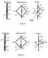
- Fig. 8illustrates how the cell structure of Fig. 7 may be altered to include anchors.
- the cell 500may be crafted to include flaring barbs 520.
- barbs 520will be sized and positioned to facilitate anchoring the stent, graft, endograft or overall device to the vessel in which it is being deployed. Accordingly, to achieve this type of anchoring, the barbs 520 are formed or deployed on the cell in a manner that allows for them to extend outside the outer diameter of the device.
- the use of barbs to anchor devices in vesselsin known in the art and it is within the skill of the ordinary artisan to devise a construction that includes barbs of desired properties for the desired use.
- the anchorsmay be included with cells configured to provide retention projections upon expansion, or alternatively, be used to the exclusion of retention projections.
- Figure 9depicts the use of a barb 520 and a strut 505 configuration that allows the barb to reside inside the cell frame when collapsed. Housing the barb in an interior area may reduce inadvertent pricks or snags while sheathing and deploying.
- Figure 10depicts a similar interior positioning of the barb 520, this time in a central location and wherein the barb 520 is adapted for deployment with a "W" shaped retention projection 510.
- Figure 10illustrates the potential for inclusion of multiple barbs 520 on a single cell member 500.
- the cell 501is configured to internally house the barbs 520 in its unexpanded state and flare the barbs outwardly from two sides of the retention mechanism during nitinol expansion.
- the geometry and configuration of the cells with projections and/or barbsis virtually limitless.
- only the barbsare designed to extend beyond the outer diameter of the device. This construction hinders the possibility of out-of-plane bending that could hamper the effectiveness of the anchoring.
- the use of the self-flaring barbs described hereinhelps reduce problems associated with sheathing devices having an anchor (hooks or barbs), and potentially allows for recapturability. Recapture may be achieved by reversing the differential shortening by causing the cell to collapse causing the barb to be retrieved into the interior of the cell.
Landscapes
- Health & Medical Sciences (AREA)
- Engineering & Computer Science (AREA)
- Biomedical Technology (AREA)
- Heart & Thoracic Surgery (AREA)
- Public Health (AREA)
- Transplantation (AREA)
- Cardiology (AREA)
- Veterinary Medicine (AREA)
- Oral & Maxillofacial Surgery (AREA)
- Vascular Medicine (AREA)
- Life Sciences & Earth Sciences (AREA)
- Animal Behavior & Ethology (AREA)
- General Health & Medical Sciences (AREA)
- Gastroenterology & Hepatology (AREA)
- Pulmonology (AREA)
- Prostheses (AREA)
- Medicinal Preparation (AREA)
- Pharmaceuticals Containing Other Organic And Inorganic Compounds (AREA)
Abstract
Description
- The present invention relates to a cell for a percutaneous prosthetic devices. More particularly, aortic prosthetic devices for treating abdominal aortic aneurysms having improved fixation means and methods
- An aneurysm is an abnormal dilation of a layer or layers of an arterial wall, usually caused by a systemic collagen synthetic or structural defect. An abdominal aortic aneurysm is an aneurysm in the abdominal portion of the aorta, usually located at or below the renal arteries, and may be continuous with iliac aneurysms in one or both of the two iliac arteries. An abdominal aortic aneurysm is often "infrarenal", meaning that there is a portion of healthy abdominal aorta between the aneurysm and the renal arteries. When left untreated, the aneurysm may rupture, usually causing rapid fatal hemorrhaging.
- There has been a great deal of research directed at developing less invasive; percutaneous, e.g., catheter directed, techniques for the treatment of aneurysms, specifically abdominal aortic aneurysms. This has been facilitated by the development of vascular stents, which can and have been used in conjunction with standard or thin-wall graft material in order to create a stent-graft or endograft. The potential advantages of less invasive treatments have included reduced surgical morbidity and mortality along with shorter hospital and intensive care unit stays.
- Stent-grafts or endoprostheses are now FDA approved and commercially available. The delivery procedure typically involves advanced angiographic techniques performed through vascular accesses gained via surgical cutdown of a remote artery, such as the common femoral or brachial arteries. Over a guidewire, the appropriate size introducer will be placed. The catheter and guidewire is passed through the aneurysm, and, with the appropriate size introducer housing a stent-graft, the stent-graft will be advanced along the guidewire to the appropriate position. Typical deployment of the stent-graft device requires withdrawal of an outer sheath while maintaining the position of the stent-graft with an inner-stabilizing device. Many stent-grafts are self-expanding; however, an additional angioplasty procedure, e.g., balloon angioplasty, may be required to secure the position of the stent- graft. Following the placement of the stent-graft, standard angiographic views may be obtained.
US-5843158 discusses limited expansion endoluminal prostheses. The prostheses may comprise a frame having fangible perforation reinforcement elements. These straighten on expansion of the prosthesis and limit further expansion until a predetermined expansion load is applied, at which point the reinforcement elements fail in tension.US-2005/0203607A1 relates to a stent with a structure in which two portions of the stent move towards each other on expansion. A coupling arrangement couples the two portions preventing further movement of the portions towards or away from each other.WO-92/06734A - While the above-described endoprostheses represent a significant improvement over conventional surgical techniques, there is a need to improve the endoprostheses, their method of use, and their percutaneous delivery. Accordingly, in order to provide a safe and effective alternate means for treating aneurysms, including abdominal aortic aneurysms and thoracic aortic aneurysms, a number of difficulties associated with currently known endoprostheses and their delivery systems must be overcome. One concern with the use of endoprostheses is the prevention of endo-leaks and the disruption of the normal fluid dynamics of the vasculature. Devices using any technology should preferably be simple to position and reposition as necessary, should preferably provide an acute fluid tight seal, and should preferably be anchored to prevent migration without interfering with normal blood flow in both the aneurysmal vessel as well as branching vessels. In addition, devices using the technology should preferably be able to be anchored, sealed, and maintained in bifurcated vessels, tortuous vessels, highly angulated vessels, partially diseased vessels, calcified vessels, odd shaped vessels, short vessels, and long vessels. In order to accomplish this, the endoprostheses should preferably be extendable and re-configurable while maintaining acute and long term fluid tight seals and anchoring positions. Also, in addressing these difficulties, it must be remembered that these devices must also be configured so as to allow the profile of the device to be collapsed to sizes that are optimal with percutaneous delivery systems.
- Various embodiments of the present invention offer advantageous features that may overcome the drawbacks discussed above and offer new advantages as well.
- It is an object of the invention to provide anchoring mechanisms and retention mechanisms for use with an endoprosthesis device. It is another object of the invention to provide anchoring and retention mechanisms that may reduce problems encountered with sheathing the associated device. It is yet another object of the invention to provide an anchoring mechanism that may allow for recapturability. Accordingly, the present invention harnesses the phenomena of diamond foreshortening to construct collapsible cells that include central struts that may be configured to flare out-of-plane, for example in the form of self-flaring barbs or retention projections in some embodiments.
- According to the present invention, there is provided a cell for a percutaneous intra-luminal device as defined in appended
claim 1. - It is a further object of the invention to provide self-flaring mechanisms that may serve as an endoleg retention mechanism that provides non-traumatic holding. It is also an object of the invention to provide self-flaring mechanisms that may act as hooks or barbs for anchoring intra-luminal devices.
- According to various objects and advantages of the invention, there is provided a retaining mechanism comprising self-flaring retention projections. According to one aspect of the invention, the retaining mechanisms may comprise nitinol, or other shape-memory alloy, that operationally deploys protrusions during the nitinol expansion process. An advantageous feature of the invention is that the protrusion may be configured to flare out-of-plane during device expansion or deployment to provide interiorly deployed projections mateable with gaps, windows, meshes or the like of other devices.
- Also according to the invention, there is provided an intra-luminal device having self-flaring barbs to aid attachment or anchoring of the devices. An advantageous feature of the invention is that the barbs may be configured to flare during device expansion to anchor expanding devices. Anchors configured in this manner may improve sheathabillity and afford a means of recapture. Preferably, the anchoring mechanisms are configured so that only the barbs extend beyond the outer diameter of the device being anchored. One advantageous feature of the invention is that the anchoring mechanisms and retention protrusions may be used on the same device.
- The retention protrusions and self-flaring barbs are the result of the provision of a central strut on a collapsible frame that expands in a manner that forces the strut to bend out of plane. An advantageous feature of the invention is the ability to configure the frame and strut cell assembly to result in an expanded structure having a desired geometry. The cell assembly preferably comprises nitinol or other shape memory alloy that expands after deployment. The cells of the present invention may be included in stents, grafts, endografts or any other intra-luminal device. Moreover, the cells may be part of a composite, mesh, framework or other collapsible structure commonly deployed via catheterization procedures.
- Embodiments of the invention will now be described by way of example with reference to the accompanying drawings, where like reference numerals indicate identical or functionally similar elements, and in which:
Figure 1 illustrates a percutaneous endoprosthesis device with suprarenal fixation assembled in-situ to treat an abdominal aortic aneurysm in which the invention can be used;Figure 2 is an isolation view of an embodiment of a bifurcated trunk portion of an unassembled endoprosthesis device in which the invention can be used;Figure 3 is an isolation view of an iliac leg member of an unassembled endoprosthesis device in which the invention can be used;Figure 4 illustrates the principle of foreshortening using a collapsed diamond shaped cell.Figure 5 illustrates a collapsed and expanded diamond shaped cell having a center strut that is displace out of plane due to foreshortening according to the present invention.Figure 6A-B are side views of retention mechanisms for endoleg retention according to the invention.Figure 7 includes an unexpanded, expanded front view and expanded side view of an embodiment of a cell having a "Y" shaped center strut.Figure 8 includes an unexpanded, expanded front view and expanded side view of the cell ofFigure 7 including a self-flaring barb member according to the invention.Figure 9 includes an unexpanded, expanded front view and expanded side view of an alternative embodiment of an anchoring mechanism including a self-flaring barb member according to the invention.Figure 10 includes an unexpanded, expanded front view and expanded side view of another alternative embodiment of an anchoring mechanism including a self-flaring barb member according to the invention.Figure 11 includes an unexpanded, expanded front view and expanded side view of yet another alternative embodiment of an anchoring mechanism including a self-flaring barb member according to the invention.- The present invention is based, in part, on the discovery that suprarenal fixation of endoprostheses may provide advantageous benefits. The present invention is also based, in part, or the discovery that the phenomena of diamond foreshortening may be harnessed to construct collapsible cells with central struts that may be configured to deploy self-flaring projections, such as barbs or retention mechanisms, for use with intra-luminal devices. While the present invention will be described in connection with an endoprosthesis device for treating an abdominal aortic aneurysm, one of ordinary skill in the art will recognize the universality of the advantageous aspects of the invention, including the applicability in the deployment, repositioning and capture of devices in any intra-luminal procedure.
- The various figures depict varying aspects of preferred embodiments of a suprarenal affixed endoprosthesis. An endoprosthesis system may be useful in assuring profiles more compatible with percutaneous delivery systems, assuring non-obstruction of the renal arteries, assuring non-traumatic holding of endolegs, achieving superior anchoring, and perhaps allowing for recapturability. As depicted in
Fig. 1 , the assembledendoprosthesis 10 may be configured to treat an abdominalaortic aneurysm 20. Theprosthesis 10 includes abifurcated trunk portion 30 and a pair ofendolegs 40, 45 that provides a passageway for blood from theaorta 50 to safely flow into theiliac arteries 51, 52. - As shown in
Figure 2 , thebifurcated trunk portion 30 comprises asuprarenal stent 31 attached to anaortal neck area 32 of abifurcated body 33 via hangingsutures 35. When deployed, as depicted inFig. 1 , this configuration of thebifurcated trunk portion 30 allows for device fixation above the renal arteries viasuprarenal stent 31. The hanging sutures 35 are sized so as to allow substantially unfettered flow of blood into therenal arteries 53, 54. Aortic proximal neck sealing is achieved in theaortal neck area 32 of thebifurcated body 33 in an area below therenal arteries 53, 54. The separation of the aortic proximal neck sealing of the device from the device fixation allows for the profile of the device to be reduced to sizes that make it compatible with true percutaneous delivery systems. - The
suprarenal stent 31 may comprise any suitable stent or framework that provides for fixation in the aorta. In a preferred embodiment, thestent 31 comprises a nickel titanium shape memory alloy, such as that sold under the trade name nitinol, stent, or other shape-memory alloy stent, that friction fits the stent in place via the nitinol expansion phenomena well known in the art. - The
bifurcated body 33 is hung from thestent 31 via, e.g., sutures 35 in any suitable manner. Configuring sutures and achieving a suitable attachment and orientation of thebifurcated body 33 and thesuprarenal fixation stent 31 are within the skill of those in the art. - The
bifurcated body 33 preferably comprises a nitinol fabric having dimensions of a few microns or less. The nitinol fabric may be welded to a thin frame for sturdiness. In a preferred embodiment, thebifurcated body 33 comprises nitinol fabric with a non-kink reinforcement frame (not shown). The frame is preferably a thin nitinol stent that prevents kinking of the assembly. Moreover, preferably, when deployed, the trunk self-expands and seals the proximal aortic neck area of the abdominal aortic aneurysm. - In completing the assembly, the
bifurcated trunk 30 is mated with theendolegs 40, 45 in situ. The endolegs of this embodiment comprise a pair of iliac leg endografts (ipsilateral and contralateral). Theiliac leg endografts 40, 45 may be delivered and mated with thebifurcated trunk 30 via any suitable means. To achieve this end, thebifurcated trunk 30 includes anipsilateral receiving tube 38 and acontralateral receiving tube 39, each configured to receive and be coupled to a respectiveiliac leg 40, 45. - Any suitable configuration for the
iliac legs 40, 45 may be used. In an example, theiliac legs 40, 45 comprise a suturedstent 41 to apolymeric graft 42. Preferably, as best shown inFig. 3 , theiliac legs 40, 45 comprise a polyester wovengraft 42 onto which nitinol stent rings 41 are attached. Moreover, thedistal end iliac vessel 51, 52. Alternatively, the graft may also be made of a thermoplastic (i.e. polyester) material constructed as a knit, twill or other textile construction. Alternatively, the graft may be made of another suitable material. Regardless of the graft material used, the stent rings may be attached to the graft via sutures, adhesives, heat, or any other suitable means. - As will be appreciated, sealing and anchoring the various components of the devices may be desirable. This includes anchoring the
stent ring 31 to the aortic wall, sealing the aortic proximal area of the bifurcated body with the aortic wall, anchoring and/or sealing the iliac legs with bifurcated body, sealing the iliac legs with the iliac vessels, and the like. The present invention provides novel anchoring and retaining mechanisms to achieve this end. As depicted inFigure 4 , the anchoring and retaining mechanisms of the present invention are based, in part, on the geometrical principle of differential foreshortening. As will be appreciated, when a straight line having a length (L1) between a first end and a second end is bent at a forty-five degree angle, the length or distance between the two ends shortens (L2). This principle is illustrated inFigure 4 . As shown, a collapsed diamond element 400 having sides 401, 402 of a given length (L1) spanning from a top end 403 and abottom end 404 may be allowed to expand (get longer in the circumferential direction) into a diamond shape 401. The geometric result of such expansion, assuming the overall length of the sides remains constant, is that the second length (L2) between the top end 403 andbottom end 404, or the "height" of the diamond, is shorter than the original first length (L1), or "height" of the compressed structure. Figure 5 illustrates how the principle of differential foreshortening may be harnessed to achieve the advantageous anchoring and retention features according to the invention by the provision of an interior strut. By using a shape-memory alloy, or other collapsible framework, such as nitinol, a cell structure may be configured to allow for compression and expansion. In the depicted embodiment, a collapsible cell, such as diamond 500, includes opposingsides 501, 502 (which span a distance between afirst end 503 and a second end 504) and acenter strut 505. The placement of astrut 505 along the centerline of the cell, as exemplified inFigure 5 , is that as the height, or distance between thefirst end 503 andsecond end 504 is forced to shorten, so must the height of strut. This forced shortening can be harnessed during the nitinol expansion process. To be more particular, as the cell 500 expands to its diamond shape, thecenter strut 505 must bend out of plane to accommodate the shorter distance between the two ends 503, 504. This bending results in a projection out of plane with the twoarms arms 20 mm long, and if the structure expands into a perfect diamond (900 angles), then each side of the diamond will be 10 mm long and so will be the distance between the two ends. Accordingly, the center strut will have to bend 10 mm during expansion. This 10 mm bend can be configured to form a protrusion extending perpendicular from the sides. The geometry of the protrusion is a matter of design choice and will affect the height of the protrusion.- The cell is sized so that its expanded wingspan is a desired length and orientation suitable for the intended use of the cell. The cell is preferably one of a network of cells or included as part of a lattice of shape-memory material configured into a stent, endograft, or other intra-luminal device. The cell, and the overall device, may then be collapsed to a profile suitable for sheathing and delivery in catheterization procedures. The inclusion of a collapsible cell 500, or plurality of such cells, in a device such as the iliac
leg receiving tubes bifurcated section 30 of the endoprosthesis ofFigures 1-3 allows the forced shortening to be used to provideendoleg retention projections 510 to form in the inner diameter (ID) of device. As will be appreciated by one of ordinary skill in the art, use of theseretention projections 510 provides for a method of non-traumatic holding of endolegs. Figures 6A-B depict side views of various expanded cells to demonstrate the ability to configure the cell to result inretention projections 510 of various sizes and shapes. Creating thickened or thinned areas of thestrut 505 will facilitate the bending of the strut to from desired geometries. A presently preferred embodiment is shown inFig. 6B wherein a "W" shape is formed. The "W" shape of theretention projection 510 of the cell 500 may provide optimal alignment with the "windows" 601 of the iliac leg stents.Figure 7 illustrates how thecenter strut 505 may be altered to result in alternately shapedretention projections 510. InFigure 7 , thestrut 505 is configured into a "Y" shape. Upon bending, the mouth of the "Y" will result in a frame of a three-sided pyramid shape. One of ordinary skill in the art armed with the present specification will appreciated that the cells of the present invention may be modified in size, shape, orientation, and configuration to result in expanded structures having desired dimensions and features.- In this regard,
Fig. 8 illustrates how the cell structure ofFig. 7 may be altered to include anchors. The cell 500 may be crafted to include flaringbarbs 520. Preferably,barbs 520 will be sized and positioned to facilitate anchoring the stent, graft, endograft or overall device to the vessel in which it is being deployed. Accordingly, to achieve this type of anchoring, thebarbs 520 are formed or deployed on the cell in a manner that allows for them to extend outside the outer diameter of the device. The use of barbs to anchor devices in vessels in known in the art and it is within the skill of the ordinary artisan to devise a construction that includes barbs of desired properties for the desired use. The anchors may be included with cells configured to provide retention projections upon expansion, or alternatively, be used to the exclusion of retention projections. Figure 9 depicts the use of abarb 520 and astrut 505 configuration that allows the barb to reside inside the cell frame when collapsed. Housing the barb in an interior area may reduce inadvertent pricks or snags while sheathing and deploying.Figure 10 depicts a similar interior positioning of thebarb 520, this time in a central location and wherein thebarb 520 is adapted for deployment with a "W" shapedretention projection 510.Figure 10 illustrates the potential for inclusion ofmultiple barbs 520 on a single cell member 500. In this embodiment, thecell 501 is configured to internally house thebarbs 520 in its unexpanded state and flare the barbs outwardly from two sides of the retention mechanism during nitinol expansion. As will be appreciated, the geometry and configuration of the cells with projections and/or barbs is virtually limitless. Preferably, regardless of the configuration, only the barbs are designed to extend beyond the outer diameter of the device. This construction hinders the possibility of out-of-plane bending that could hamper the effectiveness of the anchoring. The use of the self-flaring barbs described herein helps reduce problems associated with sheathing devices having an anchor (hooks or barbs), and potentially allows for recapturability. Recapture may be achieved by reversing the differential shortening by causing the cell to collapse causing the barb to be retrieved into the interior of the cell.- The applicability of the retention projections and anchors described above to an endoprosthesis device such as those described herein is clear.
Claims (7)
- A cell (500) for a percutaneous intra-luminal device comprising:a frame of material having a pair of arms and a top area and a bottom area, said frame having a collapsed state and an expanded state, wherein in said collapsed state said arms are generally straight and disposed generally parallel to each, wherein in said expanded state said arms are bent and extend generally laterally away from one another due to diamond foreshortening, and wherein the distance between the top area and the bottom area is greater in the collapsed state than in the expanded state; andcharacterised in that the cell further comprises:a centrally disposed strut (505) extending between said top area and said bottom area of said frame, wherein when said frame is in said collapsed state said strut (505) runs generally parallel to said arms and when said frame is in said expanded state at least a part of said strut (505) protrudes out of plane from said arms.
- The cell of claim 1, wherein said strut includes a weak area, said weak area operating to cause said strut (505) to bend at said weak area and defining the apex of a protrusion (510) defined by said strut.
- The cell of claim 2, wherein said strut (505) includes at least one additional weak area, whereby said strut takes on a "W" shape in said expanded state.
- The cell of claim 1, further comprising a barb member (520) associated with said strut (505), wherein said barb (520) extends in a direction opposite to a protrusion (510) defined by said strut (505).
- The cell of claim 1, wherein said cell (500) comprises nitinol.
- The cell of claim 1, wherein said cell (500) is part of an percutaneous radially expandable intra-luminal device and wherein a portion of said strut (505) protrudes into the interior of said device upon expansion.
- The cell of claim 6, wherein said strut (505) includes an associated barb (520) projection that extends beyond the outer diameter of said device upon expansion.
Applications Claiming Priority (2)
| Application Number | Priority Date | Filing Date | Title |
|---|---|---|---|
| US11/338,281US8083792B2 (en) | 2006-01-24 | 2006-01-24 | Percutaneous endoprosthesis using suprarenal fixation and barbed anchors |
| EP07250232AEP1810642B1 (en) | 2006-01-24 | 2007-01-19 | Percutaneous endoprosthesis using suprarenal fixation and barbed anchors |
Related Parent Applications (2)
| Application Number | Title | Priority Date | Filing Date |
|---|---|---|---|
| EP07250232ADivisionEP1810642B1 (en) | 2006-01-24 | 2007-01-19 | Percutaneous endoprosthesis using suprarenal fixation and barbed anchors |
| EP07250232.1Division | 2007-01-19 |
Publications (2)
| Publication Number | Publication Date |
|---|---|
| EP2055264A1 EP2055264A1 (en) | 2009-05-06 |
| EP2055264B1true EP2055264B1 (en) | 2010-03-10 |
Family
ID=37858906
Family Applications (2)
| Application Number | Title | Priority Date | Filing Date |
|---|---|---|---|
| EP09153484ACeasedEP2055264B1 (en) | 2006-01-24 | 2007-01-19 | Percutaneous endoprosthesis using suprarenal fixation and barbed anchors |
| EP07250232AActiveEP1810642B1 (en) | 2006-01-24 | 2007-01-19 | Percutaneous endoprosthesis using suprarenal fixation and barbed anchors |
Family Applications After (1)
| Application Number | Title | Priority Date | Filing Date |
|---|---|---|---|
| EP07250232AActiveEP1810642B1 (en) | 2006-01-24 | 2007-01-19 | Percutaneous endoprosthesis using suprarenal fixation and barbed anchors |
Country Status (5)
| Country | Link |
|---|---|
| US (3) | US8083792B2 (en) |
| EP (2) | EP2055264B1 (en) |
| AT (2) | ATE460137T1 (en) |
| CA (1) | CA2574941C (en) |
| DE (2) | DE602007001397D1 (en) |
Families Citing this family (59)
| Publication number | Priority date | Publication date | Assignee | Title |
|---|---|---|---|---|
| US7147661B2 (en) | 2001-12-20 | 2006-12-12 | Boston Scientific Santa Rosa Corp. | Radially expandable stent |
| US8292943B2 (en) | 2003-09-03 | 2012-10-23 | Bolton Medical, Inc. | Stent graft with longitudinal support member |
| US7763063B2 (en) | 2003-09-03 | 2010-07-27 | Bolton Medical, Inc. | Self-aligning stent graft delivery system, kit, and method |
| US20070198078A1 (en) | 2003-09-03 | 2007-08-23 | Bolton Medical, Inc. | Delivery system and method for self-centering a Proximal end of a stent graft |
| US11259945B2 (en) | 2003-09-03 | 2022-03-01 | Bolton Medical, Inc. | Dual capture device for stent graft delivery system and method for capturing a stent graft |
| US20080264102A1 (en) | 2004-02-23 | 2008-10-30 | Bolton Medical, Inc. | Sheath Capture Device for Stent Graft Delivery System and Method for Operating Same |
| US8500792B2 (en) | 2003-09-03 | 2013-08-06 | Bolton Medical, Inc. | Dual capture device for stent graft delivery system and method for capturing a stent graft |
| US9198786B2 (en) | 2003-09-03 | 2015-12-01 | Bolton Medical, Inc. | Lumen repair device with capture structure |
| CN2817768Y (en)* | 2005-05-24 | 2006-09-20 | 微创医疗器械(上海)有限公司 | Tectorium stand and host cage section thereof |
| CA2881760C (en) | 2005-11-10 | 2017-06-13 | Arshad Quadri | Balloon-expandable, self-expanding, vascular prosthesis connecting stent |
| US7655037B2 (en)* | 2008-04-17 | 2010-02-02 | Cordis Corporation | Combination barb restraint and stent attachment deployment mechanism |
| CN102076281B (en) | 2008-06-30 | 2014-11-05 | 波顿医疗公司 | Systems and methods for abdominal aortic aneurysm |
| CN102292053A (en)* | 2008-09-29 | 2011-12-21 | 卡迪尔克阀门技术公司 | Heart valve |
| WO2010040009A1 (en) | 2008-10-01 | 2010-04-08 | Cardiaq Valve Technologies, Inc. | Delivery system for vascular implant |
| US9055946B2 (en) | 2008-11-26 | 2015-06-16 | Phraxis Inc. | Anastomotic connector |
| WO2010080427A1 (en)* | 2008-12-18 | 2010-07-15 | Med Institute, Inc. | Stents and stent grafts |
| EP3284447B1 (en) | 2009-03-13 | 2020-05-20 | Bolton Medical Inc. | System for deploying an endoluminal prosthesis at a surgical site |
| CA2961053C (en) | 2009-04-15 | 2019-04-30 | Edwards Lifesciences Cardiaq Llc | Vascular implant and delivery system |
| US20110040367A1 (en)* | 2009-08-14 | 2011-02-17 | Medtronic Vascular, Inc. | Low Profile Prosthesis |
| DE102009041025A1 (en)* | 2009-09-14 | 2011-03-24 | Acandis Gmbh & Co. Kg | Medical implant |
| US9730790B2 (en) | 2009-09-29 | 2017-08-15 | Edwards Lifesciences Cardiaq Llc | Replacement valve and method |
| US8652203B2 (en) | 2010-09-23 | 2014-02-18 | Cardiaq Valve Technologies, Inc. | Replacement heart valves, delivery devices and methods |
| EP2506799A4 (en) | 2009-12-01 | 2014-10-29 | Altura Medical Inc | Modular endograft devices and associated systems and methods |
| US8740972B2 (en) | 2009-12-22 | 2014-06-03 | Cook Medical Technologies Llc | Medical device with anchor members |
| US8579964B2 (en) | 2010-05-05 | 2013-11-12 | Neovasc Inc. | Transcatheter mitral valve prosthesis |
| WO2012040240A1 (en) | 2010-09-20 | 2012-03-29 | Altura Medical, Inc. | Stent graft delivery systems and associated methods |
| US9308087B2 (en) | 2011-04-28 | 2016-04-12 | Neovasc Tiara Inc. | Sequentially deployed transcatheter mitral valve prosthesis |
| US9554897B2 (en) | 2011-04-28 | 2017-01-31 | Neovasc Tiara Inc. | Methods and apparatus for engaging a valve prosthesis with tissue |
| JP5866131B2 (en) | 2011-06-15 | 2016-02-17 | フラクシス インコーポレイテッド | Anastomotic connector |
| EP2720626B1 (en) | 2011-06-15 | 2017-06-14 | Phraxis Inc. | Anastomotic connector and system for delivery |
| US9498363B2 (en) | 2012-04-06 | 2016-11-22 | Trivascular, Inc. | Delivery catheter for endovascular device |
| EP2846743B1 (en) | 2012-04-12 | 2016-12-14 | Bolton Medical Inc. | Vascular prosthetic delivery device |
| US9345573B2 (en) | 2012-05-30 | 2016-05-24 | Neovasc Tiara Inc. | Methods and apparatus for loading a prosthesis onto a delivery system |
| EP2861182B1 (en) | 2012-06-15 | 2019-02-20 | Phraxis Inc. | Arterial and venous anchor devices forming an anastomotic connector |
| CA2881535A1 (en) | 2012-08-10 | 2014-02-13 | Altura Medical, Inc. | Stent delivery systems and associated methods |
| US10092391B2 (en)* | 2012-12-26 | 2018-10-09 | The Cleveland Clinic Foundation | Endoluminal prosthesis having modular branches and methods of deployment |
| US9675451B2 (en) | 2013-02-01 | 2017-06-13 | Medtronic CV Luxembourg S.a.r.l. | Anti-paravalvular leakage component for a transcatheter valve prosthesis |
| US9597180B2 (en)* | 2013-02-20 | 2017-03-21 | St. Jude Medical, Inc. | Transcatheter valve stent anchors |
| US10583002B2 (en) | 2013-03-11 | 2020-03-10 | Neovasc Tiara Inc. | Prosthetic valve with anti-pivoting mechanism |
| US9681951B2 (en) | 2013-03-14 | 2017-06-20 | Edwards Lifesciences Cardiaq Llc | Prosthesis with outer skirt and anchors |
| US9730791B2 (en) | 2013-03-14 | 2017-08-15 | Edwards Lifesciences Cardiaq Llc | Prosthesis for atraumatically grasping intralumenal tissue and methods of delivery |
| US9439751B2 (en) | 2013-03-15 | 2016-09-13 | Bolton Medical, Inc. | Hemostasis valve and delivery systems |
| WO2014144809A1 (en) | 2013-03-15 | 2014-09-18 | Altura Medical, Inc. | Endograft device delivery systems and associated methods |
| US9572665B2 (en) | 2013-04-04 | 2017-02-21 | Neovasc Tiara Inc. | Methods and apparatus for delivering a prosthetic valve to a beating heart |
| US11123205B2 (en) | 2013-09-24 | 2021-09-21 | Trivascular, Inc. | Tandem modular endograft |
| JP6661539B2 (en) | 2013-12-20 | 2020-03-11 | テルモ株式会社 | Vessel closure |
| US10111764B2 (en) | 2014-03-03 | 2018-10-30 | Cook Medical Technologies Llc | Prosthesis including retractable anchoring members |
| USD755384S1 (en) | 2014-03-05 | 2016-05-03 | Edwards Lifesciences Cardiaq Llc | Stent |
| US20160081823A1 (en)* | 2014-09-23 | 2016-03-24 | Cordis Corporation | Endoprosthesis with predetermined curvature formed by tri-tethers |
| US10034785B1 (en) | 2015-10-13 | 2018-07-31 | W. L. Gore & Associates, Inc. | Single site access aortic aneurysm repair method |
| EP3367967B1 (en) | 2015-10-27 | 2020-02-12 | Contego Medical, LLC | Transluminal angioplasty devices |
| US10350062B2 (en) | 2016-07-21 | 2019-07-16 | Edwards Lifesciences Corporation | Replacement heart valve prosthesis |
| CA3047097A1 (en) | 2016-12-13 | 2018-06-21 | Contego Medical Llc | Therapeutic agent coated angioplasty balloon with embolic filter and protective cover |
| EP3629945A4 (en) | 2017-05-25 | 2021-03-03 | Terumo Corporation | ADHESIVE LOCKING SYSTEMS |
| US11559387B2 (en)* | 2017-09-12 | 2023-01-24 | W. L Gore & Associates, Inc. | Substrate with rotatable struts for medical device |
| CN117481869A (en) | 2018-01-25 | 2024-02-02 | 爱德华兹生命科学公司 | Delivery system for assisting in recapture and repositioning of replacement valves after deployment |
| WO2020093012A1 (en) | 2018-11-01 | 2020-05-07 | Terumo Corporation | Occlusion systems |
| RU2742451C1 (en)* | 2020-03-04 | 2021-02-05 | Заза Александрович Кавтеладзе | Bifurcation stent-graft system for treating aneurism of abdominal aorta and method of treating aneurism of abdominal aorta using thereof |
| CA3175525A1 (en) | 2020-04-28 | 2021-11-04 | Terumo Corporation | Occlusion systems |
Family Cites Families (46)
| Publication number | Priority date | Publication date | Assignee | Title |
|---|---|---|---|---|
| US5330500A (en) | 1990-10-18 | 1994-07-19 | Song Ho Y | Self-expanding endovascular stent with silicone coating |
| US5843167A (en)* | 1993-04-22 | 1998-12-01 | C. R. Bard, Inc. | Method and apparatus for recapture of hooked endoprosthesis |
| US5876418A (en)* | 1994-01-13 | 1999-03-02 | Angiomed Ag | Device for providing a duct in a living body |
| US5609627A (en)* | 1994-02-09 | 1997-03-11 | Boston Scientific Technology, Inc. | Method for delivering a bifurcated endoluminal prosthesis |
| US6051020A (en)* | 1994-02-09 | 2000-04-18 | Boston Scientific Technology, Inc. | Bifurcated endoluminal prosthesis |
| US5397355A (en)* | 1994-07-19 | 1995-03-14 | Stentco, Inc. | Intraluminal stent |
| US5575817A (en)* | 1994-08-19 | 1996-11-19 | Martin; Eric C. | Aorto femoral bifurcation graft and method of implantation |
| US5683449A (en)* | 1995-02-24 | 1997-11-04 | Marcade; Jean Paul | Modular bifurcated intraluminal grafts and methods for delivering and assembling same |
| US5591197A (en)* | 1995-03-14 | 1997-01-07 | Advanced Cardiovascular Systems, Inc. | Expandable stent forming projecting barbs and method for deploying |
| CA2171896C (en)* | 1995-03-17 | 2007-05-15 | Scott C. Anderson | Multi-anchor stent |
| DE69635659T2 (en)* | 1995-06-01 | 2006-07-06 | Meadox Medicals, Inc. | IMPLANTABLE INTRALUMINARY PROSTHESIS |
| US6814747B2 (en)* | 1995-09-08 | 2004-11-09 | Anthony Walter Anson | Surgical graft/stent system |
| US5824037A (en)* | 1995-10-03 | 1998-10-20 | Medtronic, Inc. | Modular intraluminal prostheses construction and methods |
| US6193745B1 (en)* | 1995-10-03 | 2001-02-27 | Medtronic, Inc. | Modular intraluminal prosteheses construction and methods |
| US5843158A (en)* | 1996-01-05 | 1998-12-01 | Medtronic, Inc. | Limited expansion endoluminal prostheses and methods for their use |
| US5824042A (en)* | 1996-04-05 | 1998-10-20 | Medtronic, Inc. | Endoluminal prostheses having position indicating markers |
| JP4042998B2 (en)* | 1997-01-29 | 2008-02-06 | クック インコーポレイテッド | Bell bottom modular stent graft |
| US5868783A (en)* | 1997-04-16 | 1999-02-09 | Numed, Inc. | Intravascular stent with limited axial shrinkage |
| US5984955A (en)* | 1997-09-11 | 1999-11-16 | Wisselink; Willem | System and method for endoluminal grafting of bifurcated or branched vessels |
| US6733523B2 (en)* | 1998-12-11 | 2004-05-11 | Endologix, Inc. | Implantable vascular graft |
| US6187036B1 (en)* | 1998-12-11 | 2001-02-13 | Endologix, Inc. | Endoluminal vascular prosthesis |
| US6162246A (en)* | 1999-02-16 | 2000-12-19 | Barone; Hector Daniel | Aortic graft and method of treating abdominal aortic aneurysms |
| US6648913B1 (en)* | 1999-06-07 | 2003-11-18 | Scimed Life Systems, Inc. | Guidewire-access modular intraluminal prosthesis with connecting section |
| US6663667B2 (en)* | 1999-12-29 | 2003-12-16 | Edwards Lifesciences Corporation | Towel graft means for enhancing tissue ingrowth in vascular grafts |
| US6468301B1 (en)* | 2000-03-27 | 2002-10-22 | Aga Medical Corporation | Repositionable and recapturable vascular stent/graft |
| US6517573B1 (en)* | 2000-04-11 | 2003-02-11 | Endovascular Technologies, Inc. | Hook for attaching to a corporeal lumen and method of manufacturing |
| US6942691B1 (en)* | 2000-04-27 | 2005-09-13 | Timothy A. M. Chuter | Modular bifurcated graft for endovascular aneurysm repair |
| US7226474B2 (en)* | 2000-05-01 | 2007-06-05 | Endovascular Technologies, Inc. | Modular graft component junctions |
| US6676698B2 (en)* | 2000-06-26 | 2004-01-13 | Rex Medicol, L.P. | Vascular device with valve for approximating vessel wall |
| US6773454B2 (en)* | 2000-08-02 | 2004-08-10 | Michael H. Wholey | Tapered endovascular stent graft and method of treating abdominal aortic aneurysms and distal iliac aneurysms |
| WO2002030329A2 (en)* | 2000-10-13 | 2002-04-18 | Rex Medical, L.P. | Covered stents with side branch |
| WO2002067816A1 (en)* | 2001-02-26 | 2002-09-06 | Scimed Life Systems, Inc. | Bifurcated stent and delivery system |
| FR2826863B1 (en)* | 2001-07-04 | 2003-09-26 | Jacques Seguin | ASSEMBLY FOR PLACING A PROSTHETIC VALVE IN A BODY CONDUIT |
| US6641606B2 (en)* | 2001-12-20 | 2003-11-04 | Cleveland Clinic Foundation | Delivery system and method for deploying an endovascular prosthesis |
| US20030130720A1 (en)* | 2002-01-08 | 2003-07-10 | Depalma Donald F. | Modular aneurysm repair system |
| US7029494B2 (en)* | 2002-02-08 | 2006-04-18 | Scimed Life Systems, Inc. | Braided modular stent with hourglass-shaped interfaces |
| US7331992B2 (en)* | 2002-02-20 | 2008-02-19 | Bard Peripheral Vascular, Inc. | Anchoring device for an endoluminal prosthesis |
| US7708771B2 (en)* | 2002-02-26 | 2010-05-04 | Endovascular Technologies, Inc. | Endovascular graft device and methods for attaching components thereof |
| AU2003256633A1 (en)* | 2002-07-22 | 2004-02-09 | Timur Paul Sarac | Percutaneous endovascular apparatus for repair of aneurysms and arterial blockages |
| US7550004B2 (en)* | 2002-08-20 | 2009-06-23 | Cook Biotech Incorporated | Endoluminal device with extracellular matrix material and methods |
| US7122052B2 (en)* | 2003-09-29 | 2006-10-17 | Stout Medical Group Lp | Integral support stent graft assembly |
| EP3424463A1 (en)* | 2003-11-08 | 2019-01-09 | Cook Medical Technologies LLC | Aorta and branch vessel stent grafts and system |
| DE102004003093B4 (en)* | 2004-01-21 | 2009-01-29 | Admedes Schuessler Gmbh | Stent for insertion and expansion in a lumen |
| JP4852033B2 (en)* | 2004-03-11 | 2012-01-11 | トリバスキュラー インコーポレイテッド | Modular endovascular graft |
| EP1621159A1 (en) | 2004-07-28 | 2006-02-01 | Cordis Corporation | Abdominal aortic aneurism (AAA) low profile support structure |
| WO2007109621A2 (en)* | 2006-03-20 | 2007-09-27 | Xtent, Inc. | Apparatus and methods for deployment of linked prosthetic segments |
- 2006
- 2006-01-24USUS11/338,281patent/US8083792B2/ennot_activeExpired - Fee Related
- 2007
- 2007-01-19EPEP09153484Apatent/EP2055264B1/ennot_activeCeased
- 2007-01-19DEDE602007001397Tpatent/DE602007001397D1/enactiveActive
- 2007-01-19EPEP07250232Apatent/EP1810642B1/enactiveActive
- 2007-01-19ATAT09153484Tpatent/ATE460137T1/ennot_activeIP Right Cessation
- 2007-01-19DEDE602007005265Tpatent/DE602007005265D1/enactiveActive
- 2007-01-19ATAT07250232Tpatent/ATE434992T1/ennot_activeIP Right Cessation
- 2007-01-23CACA2574941Apatent/CA2574941C/enactiveActive
- 2011
- 2011-11-14USUS13/295,213patent/US8721707B2/enactiveActive
- 2014
- 2014-04-08USUS14/247,374patent/US20140222132A1/ennot_activeAbandoned
Also Published As
| Publication number | Publication date |
|---|---|
| DE602007005265D1 (en) | 2010-04-22 |
| US20120059452A1 (en) | 2012-03-08 |
| CA2574941A1 (en) | 2007-07-24 |
| US8083792B2 (en) | 2011-12-27 |
| US20070173929A1 (en) | 2007-07-26 |
| EP1810642A2 (en) | 2007-07-25 |
| CA2574941C (en) | 2015-01-13 |
| DE602007001397D1 (en) | 2009-08-13 |
| EP1810642A3 (en) | 2007-10-03 |
| EP1810642B1 (en) | 2009-07-01 |
| EP2055264A1 (en) | 2009-05-06 |
| ATE434992T1 (en) | 2009-07-15 |
| US8721707B2 (en) | 2014-05-13 |
| US20140222132A1 (en) | 2014-08-07 |
| ATE460137T1 (en) | 2010-03-15 |
Similar Documents
| Publication | Publication Date | Title |
|---|---|---|
| EP2055264B1 (en) | Percutaneous endoprosthesis using suprarenal fixation and barbed anchors | |
| AU750657B2 (en) | An aortic graft having a precursor gasket for repairing an abdominal aortic aneurysm | |
| US6942691B1 (en) | Modular bifurcated graft for endovascular aneurysm repair | |
| EP1433441B1 (en) | An improved stent which is easily recaptured and repositioned within the body | |
| US8177833B2 (en) | System and method for forming a junction between elements of a modular endovascular prosthesis | |
| US5755772A (en) | Radially expansible vascular prosthesis having reversible and other locking structures | |
| US7029496B2 (en) | Interlocking endoluminal device | |
| US7655037B2 (en) | Combination barb restraint and stent attachment deployment mechanism | |
| US9770350B2 (en) | Stent-graft with fixation elements that are radially confined for delivery | |
| US20140288634A1 (en) | Double-layer stent | |
| US20050033406A1 (en) | Branch vessel stent and graft | |
| US20050149166A1 (en) | Branch vessel prosthesis with anchoring device and method | |
| EP1808149A1 (en) | Intraluminal stent graft | |
| US20070038288A1 (en) | Methods and apparatuses for repairing aneurysms | |
| EP2679197A1 (en) | Sealing mechanism for expandable vascular graft | |
| WO1998027893A9 (en) | Kink resistant bifurcated prosthesis | |
| US7556643B2 (en) | Graft inside stent | |
| JP2008023334A (en) | Abdominal aortic aneurysm treatment apparatus equipped with aortic aneurysm sac access port | |
| US9956095B2 (en) | Self-expanding bridging stent with anchoring projections and methods for use | |
| US9687366B2 (en) | Endoleak mitigator for aneurysm stent-graft | |
| AU779171B2 (en) | Kink resistant bifurcated prosthesis | |
| AU2004201997A1 (en) | Kink resistant bifurcated prosthesis |
Legal Events
| Date | Code | Title | Description |
|---|---|---|---|
| PUAI | Public reference made under article 153(3) epc to a published international application that has entered the european phase | Free format text:ORIGINAL CODE: 0009012 | |
| 17P | Request for examination filed | Effective date:20090224 | |
| AC | Divisional application: reference to earlier application | Ref document number:1810642 Country of ref document:EP Kind code of ref document:P | |
| AK | Designated contracting states | Kind code of ref document:A1 Designated state(s):AT BE BG CH CY CZ DE DK EE ES FI FR GB GR HU IE IS IT LI LT LU LV MC NL PL PT RO SE SI SK TR | |
| GRAP | Despatch of communication of intention to grant a patent | Free format text:ORIGINAL CODE: EPIDOSNIGR1 | |
| AKX | Designation fees paid | Designated state(s):AT BE BG CH CY CZ DE DK EE ES FI FR GB GR HU IE IS IT LI LT LU LV MC NL PL PT RO SE SI SK TR | |
| GRAS | Grant fee paid | Free format text:ORIGINAL CODE: EPIDOSNIGR3 | |
| GRAA | (expected) grant | Free format text:ORIGINAL CODE: 0009210 | |
| AC | Divisional application: reference to earlier application | Ref document number:1810642 Country of ref document:EP Kind code of ref document:P | |
| AK | Designated contracting states | Kind code of ref document:B1 Designated state(s):AT BE BG CH CY CZ DE DK EE ES FI FR GB GR HU IE IS IT LI LT LU LV MC NL PL PT RO SE SI SK TR | |
| REG | Reference to a national code | Ref country code:GB Ref legal event code:FG4D | |
| REG | Reference to a national code | Ref country code:CH Ref legal event code:EP | |
| REG | Reference to a national code | Ref country code:IE Ref legal event code:FG4D | |
| REF | Corresponds to: | Ref document number:602007005265 Country of ref document:DE Date of ref document:20100422 Kind code of ref document:P | |
| REG | Reference to a national code | Ref country code:NL Ref legal event code:T3 | |
| PG25 | Lapsed in a contracting state [announced via postgrant information from national office to epo] | Ref country code:LT Free format text:LAPSE BECAUSE OF FAILURE TO SUBMIT A TRANSLATION OF THE DESCRIPTION OR TO PAY THE FEE WITHIN THE PRESCRIBED TIME-LIMIT Effective date:20100310 | |
| LTIE | Lt: invalidation of european patent or patent extension | Effective date:20100310 | |
| PG25 | Lapsed in a contracting state [announced via postgrant information from national office to epo] | Ref country code:AT Free format text:LAPSE BECAUSE OF FAILURE TO SUBMIT A TRANSLATION OF THE DESCRIPTION OR TO PAY THE FEE WITHIN THE PRESCRIBED TIME-LIMIT Effective date:20100310 Ref country code:FI Free format text:LAPSE BECAUSE OF FAILURE TO SUBMIT A TRANSLATION OF THE DESCRIPTION OR TO PAY THE FEE WITHIN THE PRESCRIBED TIME-LIMIT Effective date:20100310 Ref country code:PL Free format text:LAPSE BECAUSE OF FAILURE TO SUBMIT A TRANSLATION OF THE DESCRIPTION OR TO PAY THE FEE WITHIN THE PRESCRIBED TIME-LIMIT Effective date:20100310 Ref country code:SI Free format text:LAPSE BECAUSE OF FAILURE TO SUBMIT A TRANSLATION OF THE DESCRIPTION OR TO PAY THE FEE WITHIN THE PRESCRIBED TIME-LIMIT Effective date:20100310 Ref country code:LV Free format text:LAPSE BECAUSE OF FAILURE TO SUBMIT A TRANSLATION OF THE DESCRIPTION OR TO PAY THE FEE WITHIN THE PRESCRIBED TIME-LIMIT Effective date:20100310 | |
| PG25 | Lapsed in a contracting state [announced via postgrant information from national office to epo] | Ref country code:SE Free format text:LAPSE BECAUSE OF FAILURE TO SUBMIT A TRANSLATION OF THE DESCRIPTION OR TO PAY THE FEE WITHIN THE PRESCRIBED TIME-LIMIT Effective date:20100310 Ref country code:RO Free format text:LAPSE BECAUSE OF FAILURE TO SUBMIT A TRANSLATION OF THE DESCRIPTION OR TO PAY THE FEE WITHIN THE PRESCRIBED TIME-LIMIT Effective date:20100310 Ref country code:ES Free format text:LAPSE BECAUSE OF FAILURE TO SUBMIT A TRANSLATION OF THE DESCRIPTION OR TO PAY THE FEE WITHIN THE PRESCRIBED TIME-LIMIT Effective date:20100621 Ref country code:CY Free format text:LAPSE BECAUSE OF FAILURE TO SUBMIT A TRANSLATION OF THE DESCRIPTION OR TO PAY THE FEE WITHIN THE PRESCRIBED TIME-LIMIT Effective date:20100310 Ref country code:EE Free format text:LAPSE BECAUSE OF FAILURE TO SUBMIT A TRANSLATION OF THE DESCRIPTION OR TO PAY THE FEE WITHIN THE PRESCRIBED TIME-LIMIT Effective date:20100310 Ref country code:GR Free format text:LAPSE BECAUSE OF FAILURE TO SUBMIT A TRANSLATION OF THE DESCRIPTION OR TO PAY THE FEE WITHIN THE PRESCRIBED TIME-LIMIT Effective date:20100611 Ref country code:BE Free format text:LAPSE BECAUSE OF FAILURE TO SUBMIT A TRANSLATION OF THE DESCRIPTION OR TO PAY THE FEE WITHIN THE PRESCRIBED TIME-LIMIT Effective date:20100310 | |
| PG25 | Lapsed in a contracting state [announced via postgrant information from national office to epo] | Ref country code:CZ Free format text:LAPSE BECAUSE OF FAILURE TO SUBMIT A TRANSLATION OF THE DESCRIPTION OR TO PAY THE FEE WITHIN THE PRESCRIBED TIME-LIMIT Effective date:20100310 Ref country code:BG Free format text:LAPSE BECAUSE OF FAILURE TO SUBMIT A TRANSLATION OF THE DESCRIPTION OR TO PAY THE FEE WITHIN THE PRESCRIBED TIME-LIMIT Effective date:20100610 Ref country code:IS Free format text:LAPSE BECAUSE OF FAILURE TO SUBMIT A TRANSLATION OF THE DESCRIPTION OR TO PAY THE FEE WITHIN THE PRESCRIBED TIME-LIMIT Effective date:20100710 Ref country code:SK Free format text:LAPSE BECAUSE OF FAILURE TO SUBMIT A TRANSLATION OF THE DESCRIPTION OR TO PAY THE FEE WITHIN THE PRESCRIBED TIME-LIMIT Effective date:20100310 | |
| PLBE | No opposition filed within time limit | Free format text:ORIGINAL CODE: 0009261 | |
| STAA | Information on the status of an ep patent application or granted ep patent | Free format text:STATUS: NO OPPOSITION FILED WITHIN TIME LIMIT | |
| PG25 | Lapsed in a contracting state [announced via postgrant information from national office to epo] | Ref country code:PT Free format text:LAPSE BECAUSE OF FAILURE TO SUBMIT A TRANSLATION OF THE DESCRIPTION OR TO PAY THE FEE WITHIN THE PRESCRIBED TIME-LIMIT Effective date:20100712 Ref country code:DK Free format text:LAPSE BECAUSE OF FAILURE TO SUBMIT A TRANSLATION OF THE DESCRIPTION OR TO PAY THE FEE WITHIN THE PRESCRIBED TIME-LIMIT Effective date:20100310 | |
| 26N | No opposition filed | Effective date:20101213 | |
| PG25 | Lapsed in a contracting state [announced via postgrant information from national office to epo] | Ref country code:MC Free format text:LAPSE BECAUSE OF NON-PAYMENT OF DUE FEES Effective date:20110131 | |
| REG | Reference to a national code | Ref country code:CH Ref legal event code:PL | |
| PG25 | Lapsed in a contracting state [announced via postgrant information from national office to epo] | Ref country code:LI Free format text:LAPSE BECAUSE OF NON-PAYMENT OF DUE FEES Effective date:20110131 Ref country code:CH Free format text:LAPSE BECAUSE OF NON-PAYMENT OF DUE FEES Effective date:20110131 | |
| PG25 | Lapsed in a contracting state [announced via postgrant information from national office to epo] | Ref country code:LU Free format text:LAPSE BECAUSE OF NON-PAYMENT OF DUE FEES Effective date:20110119 | |
| PG25 | Lapsed in a contracting state [announced via postgrant information from national office to epo] | Ref country code:TR Free format text:LAPSE BECAUSE OF FAILURE TO SUBMIT A TRANSLATION OF THE DESCRIPTION OR TO PAY THE FEE WITHIN THE PRESCRIBED TIME-LIMIT Effective date:20100310 | |
| PG25 | Lapsed in a contracting state [announced via postgrant information from national office to epo] | Ref country code:HU Free format text:LAPSE BECAUSE OF FAILURE TO SUBMIT A TRANSLATION OF THE DESCRIPTION OR TO PAY THE FEE WITHIN THE PRESCRIBED TIME-LIMIT Effective date:20100310 | |
| REG | Reference to a national code | Ref country code:FR Ref legal event code:PLFP Year of fee payment:10 | |
| REG | Reference to a national code | Ref country code:FR Ref legal event code:PLFP Year of fee payment:11 | |
| REG | Reference to a national code | Ref country code:FR Ref legal event code:PLFP Year of fee payment:12 | |
| REG | Reference to a national code | Ref country code:DE Ref legal event code:R082 Ref document number:602007005265 Country of ref document:DE Representative=s name:PROCK, THOMAS, DR., GB | |
| REG | Reference to a national code | Ref country code:NL Ref legal event code:PD Owner name:CARDINAL HEALTH SWITZERLAND 515 GMBH; CH Free format text:DETAILS ASSIGNMENT: CHANGE OF OWNER(S), ASSIGNMENT; FORMER OWNER NAME: CORDIS CORPORATION Effective date:20200708 | |
| REG | Reference to a national code | Ref country code:DE Ref legal event code:R082 Ref document number:602007005265 Country of ref document:DE Representative=s name:PROCK, THOMAS, DR., GB Ref country code:DE Ref legal event code:R081 Ref document number:602007005265 Country of ref document:DE Owner name:CARDINAL HEALTH SWITZERLAND 515 GMBH, CH Free format text:FORMER OWNER: CORDIS CORP., MIAMI LAKES, FLA., US | |
| PGFP | Annual fee paid to national office [announced via postgrant information from national office to epo] | Ref country code:IE Payment date:20230127 Year of fee payment:17 Ref country code:FR Payment date:20230125 Year of fee payment:17 | |
| PGFP | Annual fee paid to national office [announced via postgrant information from national office to epo] | Ref country code:IT Payment date:20230120 Year of fee payment:17 Ref country code:GB Payment date:20230127 Year of fee payment:17 Ref country code:DE Payment date:20230127 Year of fee payment:17 | |
| PGFP | Annual fee paid to national office [announced via postgrant information from national office to epo] | Ref country code:NL Payment date:20230126 Year of fee payment:17 | |
| REG | Reference to a national code | Ref country code:DE Ref legal event code:R119 Ref document number:602007005265 Country of ref document:DE | |
| REG | Reference to a national code | Ref country code:NL Ref legal event code:MM Effective date:20240201 | |
| GBPC | Gb: european patent ceased through non-payment of renewal fee | Effective date:20240119 | |
| PG25 | Lapsed in a contracting state [announced via postgrant information from national office to epo] | Ref country code:DE Free format text:LAPSE BECAUSE OF NON-PAYMENT OF DUE FEES Effective date:20240801 | |
| PG25 | Lapsed in a contracting state [announced via postgrant information from national office to epo] | Ref country code:GB Free format text:LAPSE BECAUSE OF NON-PAYMENT OF DUE FEES Effective date:20240119 | |
| PG25 | Lapsed in a contracting state [announced via postgrant information from national office to epo] | Ref country code:FR Free format text:LAPSE BECAUSE OF NON-PAYMENT OF DUE FEES Effective date:20240131 | |
| PG25 | Lapsed in a contracting state [announced via postgrant information from national office to epo] | Ref country code:NL Free format text:LAPSE BECAUSE OF NON-PAYMENT OF DUE FEES Effective date:20240201 | |
| PG25 | Lapsed in a contracting state [announced via postgrant information from national office to epo] | Ref country code:NL Free format text:LAPSE BECAUSE OF NON-PAYMENT OF DUE FEES Effective date:20240201 Ref country code:GB Free format text:LAPSE BECAUSE OF NON-PAYMENT OF DUE FEES Effective date:20240119 Ref country code:FR Free format text:LAPSE BECAUSE OF NON-PAYMENT OF DUE FEES Effective date:20240131 Ref country code:DE Free format text:LAPSE BECAUSE OF NON-PAYMENT OF DUE FEES Effective date:20240801 | |
| PG25 | Lapsed in a contracting state [announced via postgrant information from national office to epo] | Ref country code:IE Free format text:LAPSE BECAUSE OF NON-PAYMENT OF DUE FEES Effective date:20240119 | |
| PG25 | Lapsed in a contracting state [announced via postgrant information from national office to epo] | Ref country code:IE Free format text:LAPSE BECAUSE OF NON-PAYMENT OF DUE FEES Effective date:20240119 | |
| PG25 | Lapsed in a contracting state [announced via postgrant information from national office to epo] | Ref country code:IT Free format text:LAPSE BECAUSE OF NON-PAYMENT OF DUE FEES Effective date:20240119 |