EP2055228B1 - Wireless flow sensor - Google Patents
Wireless flow sensorDownload PDFInfo
- Publication number
- EP2055228B1 EP2055228B1EP08253554AEP08253554AEP2055228B1EP 2055228 B1EP2055228 B1EP 2055228B1EP 08253554 AEP08253554 AEP 08253554AEP 08253554 AEP08253554 AEP 08253554AEP 2055228 B1EP2055228 B1EP 2055228B1
- Authority
- EP
- European Patent Office
- Prior art keywords
- radio frequency
- masking element
- tag
- frequency tag
- sensor
- Prior art date
- Legal status (The legal status is an assumption and is not a legal conclusion. Google has not performed a legal analysis and makes no representation as to the accuracy of the status listed.)
- Active
Links
- 230000000873masking effectEffects0.000claimsdescription72
- 239000012530fluidSubstances0.000claimsdescription63
- 230000004044responseEffects0.000claimsdescription32
- 238000000034methodMethods0.000claimsdescription24
- 239000004020conductorSubstances0.000claimsdescription6
- 238000004891communicationMethods0.000claimsdescription5
- 238000001228spectrumMethods0.000claimsdescription5
- 230000000737periodic effectEffects0.000claimsdescription4
- 210000001175cerebrospinal fluidAnatomy0.000description22
- 239000000463materialSubstances0.000description12
- 238000000576coating methodMethods0.000description11
- 208000003906hydrocephalusDiseases0.000description11
- 239000011248coating agentSubstances0.000description10
- 238000012544monitoring processMethods0.000description9
- 238000002513implantationMethods0.000description8
- 230000008859changeEffects0.000description5
- 230000008878couplingEffects0.000description5
- 238000010168coupling processMethods0.000description5
- 238000005859coupling reactionMethods0.000description5
- 238000005259measurementMethods0.000description5
- 239000000560biocompatible materialSubstances0.000description4
- 210000004556brainAnatomy0.000description4
- 230000006870functionEffects0.000description3
- 230000007246mechanismEffects0.000description3
- 229920000642polymerPolymers0.000description3
- 238000013519translationMethods0.000description3
- 230000002861ventricularEffects0.000description3
- 239000003990capacitorSubstances0.000description2
- 210000002987choroid plexusAnatomy0.000description2
- 230000001276controlling effectEffects0.000description2
- 238000001816coolingMethods0.000description2
- 230000002596correlated effectEffects0.000description2
- 238000010438heat treatmentMethods0.000description2
- 229920001296polysiloxanePolymers0.000description2
- 229920002635polyurethanePolymers0.000description2
- 239000004814polyurethaneSubstances0.000description2
- 238000012545processingMethods0.000description2
- 239000011540sensing materialSubstances0.000description2
- 239000000758substrateSubstances0.000description2
- RYGMFSIKBFXOCR-UHFFFAOYSA-NCopperChemical compound[Cu]RYGMFSIKBFXOCR-UHFFFAOYSA-N0.000description1
- 239000004698PolyethyleneSubstances0.000description1
- BQCADISMDOOEFD-UHFFFAOYSA-NSilverChemical compound[Ag]BQCADISMDOOEFD-UHFFFAOYSA-N0.000description1
- 229910001069Ti alloyInorganic materials0.000description1
- RTAQQCXQSZGOHL-UHFFFAOYSA-NTitaniumChemical compound[Ti]RTAQQCXQSZGOHL-UHFFFAOYSA-N0.000description1
- 230000002159abnormal effectEffects0.000description1
- 238000009825accumulationMethods0.000description1
- 239000000853adhesiveSubstances0.000description1
- 230000001070adhesive effectEffects0.000description1
- 239000000956alloySubstances0.000description1
- 229910045601alloyInorganic materials0.000description1
- 229910052782aluminiumInorganic materials0.000description1
- XAGFODPZIPBFFR-UHFFFAOYSA-NaluminiumChemical compound[Al]XAGFODPZIPBFFR-UHFFFAOYSA-N0.000description1
- 239000000788chromium alloySubstances0.000description1
- 239000005321cobalt glassSubstances0.000description1
- 239000002131composite materialSubstances0.000description1
- 229910052802copperInorganic materials0.000description1
- 239000010949copperSubstances0.000description1
- 238000013500data storageMethods0.000description1
- 230000001419dependent effectEffects0.000description1
- 238000010586diagramMethods0.000description1
- 238000003618dip coatingMethods0.000description1
- 230000000694effectsEffects0.000description1
- PCHJSUWPFVWCPO-UHFFFAOYSA-NgoldChemical compound[Au]PCHJSUWPFVWCPO-UHFFFAOYSA-N0.000description1
- 229910052737goldInorganic materials0.000description1
- 239000010931goldSubstances0.000description1
- 210000003128headAnatomy0.000description1
- 230000001939inductive effectEffects0.000description1
- 238000004519manufacturing processMethods0.000description1
- 230000013011matingEffects0.000description1
- 229910052751metalInorganic materials0.000description1
- 239000002184metalSubstances0.000description1
- 150000002739metalsChemical class0.000description1
- 238000012986modificationMethods0.000description1
- 230000004048modificationEffects0.000description1
- 238000012806monitoring deviceMethods0.000description1
- 230000000926neurological effectEffects0.000description1
- 231100000252nontoxicToxicity0.000description1
- 230000003000nontoxic effectEffects0.000description1
- 230000000704physical effectEffects0.000description1
- 239000004033plasticSubstances0.000description1
- 229920003023plasticPolymers0.000description1
- -1polyethylenePolymers0.000description1
- 229920000573polyethylenePolymers0.000description1
- 230000001681protective effectEffects0.000description1
- 238000010079rubber tappingMethods0.000description1
- 229910052709silverInorganic materials0.000description1
- 239000004332silverSubstances0.000description1
- 210000003625skullAnatomy0.000description1
- 239000002904solventSubstances0.000description1
- 210000000278spinal cordAnatomy0.000description1
- 238000005507sprayingMethods0.000description1
- 239000010935stainless steelSubstances0.000description1
- 229910001220stainless steelInorganic materials0.000description1
- 230000003068static effectEffects0.000description1
- 238000007920subcutaneous administrationMethods0.000description1
- 238000002560therapeutic procedureMethods0.000description1
- 210000001519tissueAnatomy0.000description1
- 239000010936titaniumSubstances0.000description1
- 229910052719titaniumInorganic materials0.000description1
- 230000002792vascularEffects0.000description1
Images


Classifications
- A—HUMAN NECESSITIES
- A61—MEDICAL OR VETERINARY SCIENCE; HYGIENE
- A61B—DIAGNOSIS; SURGERY; IDENTIFICATION
- A61B5/00—Measuring for diagnostic purposes; Identification of persons
- A61B5/0002—Remote monitoring of patients using telemetry, e.g. transmission of vital signals via a communication network
- A61B5/0015—Remote monitoring of patients using telemetry, e.g. transmission of vital signals via a communication network characterised by features of the telemetry system
- A—HUMAN NECESSITIES
- A61—MEDICAL OR VETERINARY SCIENCE; HYGIENE
- A61B—DIAGNOSIS; SURGERY; IDENTIFICATION
- A61B5/00—Measuring for diagnostic purposes; Identification of persons
- A61B5/0002—Remote monitoring of patients using telemetry, e.g. transmission of vital signals via a communication network
- A61B5/0031—Implanted circuitry
- A—HUMAN NECESSITIES
- A61—MEDICAL OR VETERINARY SCIENCE; HYGIENE
- A61B—DIAGNOSIS; SURGERY; IDENTIFICATION
- A61B5/00—Measuring for diagnostic purposes; Identification of persons
- A61B5/0059—Measuring for diagnostic purposes; Identification of persons using light, e.g. diagnosis by transillumination, diascopy, fluorescence
- A61B5/0075—Measuring for diagnostic purposes; Identification of persons using light, e.g. diagnosis by transillumination, diascopy, fluorescence by spectroscopy, i.e. measuring spectra, e.g. Raman spectroscopy, infrared absorption spectroscopy
- A—HUMAN NECESSITIES
- A61—MEDICAL OR VETERINARY SCIENCE; HYGIENE
- A61B—DIAGNOSIS; SURGERY; IDENTIFICATION
- A61B5/00—Measuring for diagnostic purposes; Identification of persons
- A61B5/07—Endoradiosondes
- A61B5/076—Permanent implantation
- A—HUMAN NECESSITIES
- A61—MEDICAL OR VETERINARY SCIENCE; HYGIENE
- A61M—DEVICES FOR INTRODUCING MEDIA INTO, OR ONTO, THE BODY; DEVICES FOR TRANSDUCING BODY MEDIA OR FOR TAKING MEDIA FROM THE BODY; DEVICES FOR PRODUCING OR ENDING SLEEP OR STUPOR
- A61M27/00—Drainage appliance for wounds or the like, i.e. wound drains, implanted drains
- A61M27/002—Implant devices for drainage of body fluids from one part of the body to another
- A61M27/006—Cerebrospinal drainage; Accessories therefor, e.g. valves
- A—HUMAN NECESSITIES
- A61—MEDICAL OR VETERINARY SCIENCE; HYGIENE
- A61M—DEVICES FOR INTRODUCING MEDIA INTO, OR ONTO, THE BODY; DEVICES FOR TRANSDUCING BODY MEDIA OR FOR TAKING MEDIA FROM THE BODY; DEVICES FOR PRODUCING OR ENDING SLEEP OR STUPOR
- A61M2205/00—General characteristics of the apparatus
- A61M2205/33—Controlling, regulating or measuring
- A61M2205/3331—Pressure; Flow
- A—HUMAN NECESSITIES
- A61—MEDICAL OR VETERINARY SCIENCE; HYGIENE
- A61M—DEVICES FOR INTRODUCING MEDIA INTO, OR ONTO, THE BODY; DEVICES FOR TRANSDUCING BODY MEDIA OR FOR TAKING MEDIA FROM THE BODY; DEVICES FOR PRODUCING OR ENDING SLEEP OR STUPOR
- A61M2205/00—General characteristics of the apparatus
- A61M2205/35—Communication
- A61M2205/3507—Communication with implanted devices, e.g. external control
- A61M2205/3523—Communication with implanted devices, e.g. external control using telemetric means
Definitions
- the present applicationgenerally relates to devices and methods for non-invasively monitoring and/or measuring the flow of a fluid, and more particularly for monitoring and/or measuring the flow of a fluid in an implantable medical device.
- treatment of hydrocephaluscan involve monitoring the flow rate of cerebrospinal fluid through a hydrocephalus shunt.
- Hydrocephalusis a neurological condition that is caused by the abnormal accumulation of cerebrospinal fluid (CSF) within the ventricles, or cavities, of the brain.
- CSFcerebrospinal fluid
- CSFis a clear, colorless fluid that is primarily produced by the choroid plexus and surrounds the brain and spinal cord, aiding in their protection.
- Hydrocephaluscan arise when the normal drainage of CSF in the brain is blocked in some way, which creates an imbalance between the amount of CSF produced by the choroid plexus and the rate at which CSF is absorbed into the bloodstream, thereby increasing pressure on the brain.
- Hydrocephalusis most often treated by surgically implanting a shunt system in a patient.
- the shunt systemdiverts the flow of CSF from the ventricle to another area of the body where the CSF can be absorbed as part of the circulatory system.
- Shunt systemscome in a variety of models and typically share similar functional components. These components include a ventricular catheter, which is introduced through a burr hole in the skull and implanted in the patient's ventricle, a drainage catheter that carries the CSF to its ultimate drainage site, and optionally a flow-control mechanism, e.g., shunt valve, that regulates the one-way flow of CSF from the ventricle to the drainage site to maintain normal pressure within the ventricles. It is this flow of CSF which may need to be measured.
- a flow-control mechanisme.g., shunt valve
- measuring the flow of CSFcan be accomplished by a flow sensor using temperature differentials between two points, e.g., with a mechanism for heating or cooling the CSF in a particular section of the catheter.
- a flow sensorcapable of more accurate and/or direct measurements of flow, without the need for heating or cooling equipment, and to provide a straightforward way to retrieve the measurements from the sensor.
- Such considerationscan apply to a wide range of applications involving the measurement of gas and fluid flow, including CSF, within an implanted device or an embedded, encapsulated, or relatively inaccessible space.
- WO 20071081741discloses a fluid flow monitoring system, in which a structure for implantation in association with vascular tissue is provided.
- a fluid flow monitoring apparatusis supported on the structure to generate a signal related to fluid flow.
- a wireless transmitter supported on the structuretransmits the signal outside the body.
- a reader external to the bodyis provided for wirelessly energizing the monitoring apparatus and transmitter and for receiving the transmitted signal. The external reader also displays the fluid flow velocity and/or rate.
- US 2006/020239discloses an implantable device for sensing CSF flow through an implantable ventricular shunt.
- the sensing deviceis implanted with the CSF shunt, and includes a flow sensor to sense flow rate or shunt blockage.
- the sensing deviceis either placed within or adjacent to the fluid path through the shunt.
- the sensing devicetransmits the sensed flow rate to an external monitoring device by wireless telemetry.
- the sensing devicemay be integrally formed as part of the shunt, or clamped onto a portion of the shunt, in which case the sensing device may be reusable.
- An external monitorreceives the transmitted flow signal and presents information based on the flow signal.
- the sensing devicemay be inductively powered or include its own power supply.
- WO 2006/048664discloses a medical device for implantation in a body.
- the deviceincludes a substrate formed from a material capable of acting as an active sensing material for sensing a physiologically or clinically relevant parameter; at least one sensor for sensing a physiologically or clinically relevant parameter, each sensor including a portion of the substrate which is configured to act as an active sensing material; and telemetric communication means coupled to said at least one sensor for telemetrically transmitting data related to a parameter sensed by the at least one sensor to a remote device.
- US 2005/165317discloses a medical device for implantation in a body comprising one or more sensors for sensing a physiologically or clinically relevant parameter; and telemetric communications means for telemetrically transmitting data related to a parameter sensed by the one or more sensors to a remote device.
- the inventionprovides an implantable sensor and a method defined by the independant claims. Optional features a included in the dependent claims.
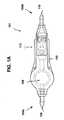
- FIG. 1Ais a top view of one exemplary implantable valve suitable for use in a hydrocephalus shunt and including a flow sensor.
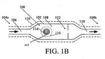
- FIG. 1Bis a schematic view of one exemplary embodiment of an implantable sensor having a housing with a radio frequency tag and a masking element disposed therein for measuring the flow of a fluid therethrough;
- FIG. 2Ais a top view of one exemplary embodiment of a radio frequency tag and a masking element for use with the implantable sensor shown in FIG. 1B ;
- FIG. 2Bis a top view of the radio frequency tag and masking element shown in FIG. 2A following rotation of the masking element;
- FIG. 3is a schematic view of an exemplary configuration for coupling the flow of a fluid to a radio frequency tag and/or masking element to cause rotation thereof;
- FIG. 4is a graph illustrating amplitude vs. frequency characteristics of an exemplary response from a radio frequency tag in an implantable sensor
- FIG. 5is a top view of another embodiment of a radio frequency tag and a masking element
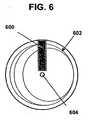
- FIG. 6is a top view of another embodiment of a radio frequency tag and a masking element
- FIG. 7Ais a top view of another embodiment of a radio frequency tag and a masking element
- FIG. 7Bis a top view the radio frequency tag and masking element shown in FIG. 7A following translation of the masking element and/or radio frequency tag;
- FIG. 8is a schematic view of an exemplary configuration for coupling the flow of a fluid to a radio frequency tag and/or masking element to cause translation thereof;
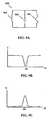
- FIG. 9Ais a schematic diagram of one exemplary model of a circuit having resonance characteristics
- FIG 9Bis a graph of an output voltage signal as a function of frequency for the circuit shown in FIG. 9A ;
- FIG 9Cis a graph of an output voltage signal as a function of frequency for the circuit shown in FIG. 9A ;
- FIG. 10is a perspective view of an exemplary reading device for reading a flow rate from an implantable sensor.
- FIG. 11illustrates the implantable sensor shown in FIG. 1 implanted in a body and being read by the reading device shown in FIG. 10 .
- the present applicationgenerally provides methods and devices for non-invasively measuring or quantifying the flow of a fluid through as device and for indicating that information to another device, e.g., telemetrically.
- the methods and devicesare particularly useful in the context of implantable devices, such as hydrocephalus shunts and associated valves. While the description herein sometimes refers to hydrocephalus shunts, one skilled in the art will understand that the devices and methods described herein can be used in a wide variety of methods and devices in which it is desirable to measure fluid flow.
- FIG. 1Aillustrates one exemplary embodiment of an implantable sensor in the context of an implantable valve for a hydrocephalus shunt.
- the implantable valve 101can include a housing 102 with proximal and distal ends 104a, 104b for receiving fluid flow (such as CSF) therethrough between an inlet port 106 and an outlet port 110.
- the housing 102can have virtually any configuration, shape, and size. In many embodiments, the size and shape of the housing 102 can be adapted for implantation in a body, e.g., subcutaneous implantation. In the embodiment shown in FIG.
- the housing 102has a substantially linear configuration with a reservoir 108 having a larger area than the ports 106, 110 which can be advantageous for checking the shunt's patency, tapping the CSF, or to administer therapy.
- the reservoir 108can also house a flow sensor, as will be described in more detailed below, and can also house a pressure sensor for measuring the pressure of fluid in the reservoir.
- suitable pressure sensorsare described in U.S. Patent Application No. 10/907,665 , entitled “Pressure Sensing Valve” by Mauge et al., filed April 11, 2005 (now published as U.S. Publication No. 2006-0211946 A1 ), and in U.S. Patent No. 5,321,989 , U.S. Patent No.
- the implantable valve 101can also include a valve assembly 112 for controlling the flow of fluid through the valve 101 according to remotely or telemetrically selectable settings.
- a coatingcan be disposed over the valve 101. Further information on implantable valves can be obtained from U.S. Publication No. 2006-0211946 A1 , referenced above.
- FIG. 1Bschematically illustrates one exemplary embodiment of an implantable sensor in the housing 102.
- Fluide.g., CSF
- Fluidcan flow as indicated by directional arrows through the housing 102 from an inlet (fluid entry) port 106 at the proximal end 104a, through a reservoir 108, and out an outlet (fluid exit) port 110 at the distal end 104b.
- the reservoir 108is not necessary (for example, the housing can be in the form of a catheter or tube), but can be advantageous for accommodating other components of the sensor or device therein.
- the sensor 100can also have a radio frequency (RF) tag 114 disposed in the reservoir 108, a masking element 115 associated with the RF tag 114 (for clarity, the RF tag 114 and the masking element 115 are represented together in FIG. 1B , although they need not be one component, or be similarly sized and oriented). Moreover, while the RF tag and masking element are shown disposed within the reservoir 108, they can be positioned at any location within a fluid system as long as they can be used to indicate a flow rate of fluid in the system.
- RFradio frequency
- the RF tag 114 and the masking element 115are configured to move relative to one another in response to and/or in relation to the rate of flow of fluid through the housing, and to indicate the rate of fluid flow to an external reading device.
- the RF tag 114can further store data, such as identification information (for example, for the sensor and/or for the patient) and flow rate history, which can be communicated to the external reading device.
- the housing 102can also contain a valve assembly for controlling the flow of fluid from the inlet port 106 to the outlet port 110, the sensor 100 measuring the controlled flow of fluid therethrough.
- the proximal and distal ends 104a, 104b of the sensor 100can each be open and adapted to couple to another medical device, such as a catheter.
- FIG. 2Ashows one exemplary embodiment of a masking element 115 associated with an RF tag 114 in which the masking element 115 is in the form of a disk with a conductive portion 202 and a non-conductive (or differently conductive) portion 208.
- the conductive portion 202can be a material, such as silver, gold, copper, aluminum, or others known in the art, etc., deposited on the disk.
- the conductive potion 202can also be attached or coupled to the disk, or it can be a non-circular portion that fits together with a non-conductive portion 208 to form the complete disk, and so on.
- the conductive portion 202can have a variety of shapes, but as shown it is in the shape of a spiral. Alternatively, the conductive portion can be in the shape of a strip of varying width, can have one or more discrete portions of varying size (e.g., a plurality of discrete rectangular shapes), and can have virtually any size and shape that is rotationally asymmetric. As shown in FIG. 2A , the RF tag 114 can be disposed behind the masking element, and particularly behind the spiral portion formed of conductive material 202. (In other embodiments, the RF tag can be disposed behind or in front of the masking element.) In use, the flow of a fluid through a housing 102, such as is shown in FIG.
- FIG. 2Billustrates one possible result of such relative movement.
- a narrow portion of the conductive material 202covers the RF tag 114.
- the response of the RF tag 114 to an external signal (e.g., from a reading device emitting a signal at one or more radio frequencies) in FIG. 2Acan differ from that of FIG. 2B and can indicate such relative position and/or movement.
- a characteristic of the response of the RF tag 114can change depending on the relative position or motion of the masking element 115 and the RF tag 114, to indicate the flow rate of fluid within the sensor housing.
- the masking element 115can rotate around its central axis 206 at a speed relative to the RF tag 114 to indicate a fluid flow rate.
- an element 300can be coupled to fluid flowing in direction 302 in a housing 102 via surface features 304 formed on the element 300, causing the element 300 to rotate as shown by arrow 306.
- the element 300can be a masking element 115 itself or alternatively it can be coupled to the masking element 115, for example, via a shaft, gears, and so on.
- the resulting relative motion of the masking element 115 and the RF tag 114can be manifested as a periodic radio frequency signal, such as is shown in FIG. 4 .
- the period of the signal(for example, the periodicity of the f max peaks in FIG. 4 , or other metric) can be correlated to the flow rate of the fluid.
- the nature of the rotation of the masking element 115 relative to the RF tag 114can vary and can be used to sense or measure other characteristics.
- the masking element 115in response to a pressure from flowing fluid the masking element 115 can rotate to a position relative to the RF tag 114 and stop.
- a spring 308can be disposed on the rotational axis of element 300 to resist the rotation thereof, and the spring 308 can be calibrated such that a given force or pressure causes a known degree of rotation, or rotational deflection, in the element 300.
- the resulting relative position of the masking element 115 and the RF tagcan indicate the pressure via the response of the RF tag to a radio frequency signal, as described above.
- FIG. 5shows an exemplary masking element 500 in the form of a disk which includes a conductive portion 504 disposed within a disk of non-conductive, or differently conductive, material 508.
- the conductive portion 504is in the form of a circle sized to cover the RF tag 502 completely, although in other embodiments, the conductive portion can be adapted to cover the RF tag 502 partially.
- the masking element 500can be coupled to flowing fluid so as to rotate around a central axis 506 in relation to the rate of flow, as previously described. Rotation of the masking element 500 can result in a periodic sudden change or discontinuity in the RF tag's response and thereby indicate the flow rate.
- a masking element 600can be in the form of a rectangle, square, or virtually any other shape, and it can be associated with an RF tag 602 having an asymmetric shape.
- the RF tag 602can be in the form of a disk with a rotationally asymmetric antenna pattern formed thereon. The pattern can include, for example, antenna lines with varying width, spacing, orientation, and so on.
- the masking element 600can be fixed within the housing, and the disk forming the RF tag 602 can be coupled to flowing fluid, e.g., in the housing as shown in FIG. 1B , so as to rotate around axis 604 in relation to the flow rate, as previously described.
- Such rotationcan cause a change or variations in the response of the RF tag 602 as the conductive masking element 600 covers different portions of the asymmetric antenna of the RF tag 602.
- the responsecan have characteristics, such as resonance frequency, harmonic spectra, decay characteristics, and/or Q factor, which can change as a result of such rotation and which can be detected in the response of the RF tag 602 to a radio frequency signal emitted by a reading device.
- the RF tag 602can be fixed within the housing and the masking element 600 can be adapted to rotate around an axis or otherwise move relative to the RF tag 602.
- the masking elementcan be configured to translate relative to the RF tag.
- FIG. 7Ashows a masking element 700 formed of a conductive material in the shape of a wedge and associated with an RF tag 702. As the masking element 700 translates relative to the RF tag 702, it covers a different portion of the RF tag 702 (for example as shown in FIG. 7B ), resulting a measurable difference in the RF tag's response, as previously described.
- the masking element 700can be coupled to the flow of fluid through the sensor housing in a variety of configurations. For example, the configuration described above in connection with FIG. 3 can be adapted such that rotation of the element 300 causes translation of the masking element 700, for example via a rack and pinion gearing.
- a sliding element 800can be disposed in a housing 102.
- the sliding element 800can be configured to receive a force of fluid flowing in direction 802 against a proximal end 804 thereof or against elements 806, and to translate in response thereto.
- a spring 808 or other biasing elementcan be configured to provide a force against a distal end 810 of the sliding element 800 that resists the force presented on the sliding element 800 by flowing fluid, and the spring 804 can be calibrated such that the deflection of the sliding element 800 corresponds to a force or pressure from the fluid flow.
- the sliding element 800can be coupled to a masking element, such as masking element 700, to effect translational movement thereof.
- the masking element and the RF tagcan have a wide variety of further configurations, including virtually any configuration in which a masking element and an RF tag move relative to one another to measure a rate of fluid flow and/or pressure.
- a variety of masking element shapescan be provided, in some embodiments only one or both of the masking element and the RF tag can be configured to move relative to the other, and so on.
- the masking elementcan physically contact the circuit of the RF tag to thereby change its properties (resistance, capacitance, inductance, etc.) and/or alter connections between conductive elements on the RF tag, for example connecting conductive branches of a circuit, or breaking such connections.
- the masking elementcovers or is disposed in between the reading device and the RF tag.
- the location of the RF tag and masking elementcan vary within the housing and are not limited to those shown in the illustrated embodiments.
- any mechanism suitable to convert the flow of a fluid to rotational or translational movementcan be provided, the foregoing embodiments being by way of example only. Further, many of the embodiments described herein can be adapted to determine or can be correlated to a pressure of fluid in a housing rather than a flow rate.
- the shape, technical specifications, and size of the RF tag 114can vary widely.
- a relatively small RF tagcan be used so as to minimize the footprint of the tag in the device, for example with dimensions in a range of about 5mm to 10mm, but in other embodiments, tags with dimensions of about 3mm to 50 mm can be used and any size is possible.
- the RF tag 114can be chipless, and its physical/electromagnetic parameters can be used to determine a flow rate.
- the RF tag 114need not have the capability to store data or to communicate according to a protocol, and need not have processing circuitry or digital logic.
- a chipless RF tagcan provide a circuit (for example, having measurable characteristics, such as a tank circuit) and can be powered from the reading device signal.
- Such an RF tagcan be advantageous due to its relatively low power requirements, and need not have the ability to communicate stored data or "identify" itself.
- the RF tag 114can be chip-based, and can provide data storage for storing additional information related to the application.
- chip-based tagsare the commonly used RF identification tags. Some of these RF identification tags provide minimal information (such as a TRUE or FALSE value), while others can store several bytes of data.
- a chip-based RF tagcan include processing circuitry, digital logic, a separate antenna, and/or a battery.
- the RF tag 114can include a memory for storing data related to the patient and/or sensor.
- the RF tag 114can store sensed pressure data, sensor identification information (e.g., implantation date, sensor type, and sensor identifier code), sensor calibration data, historical data stored from the sensor, tag identification information (e.g., implantation date, tag type, and tag identifier code), and/or patient data (e.g., desired CSF flow rate, previous sensor measurements, and patient medical history).
- sensor identification informatione.g., implantation date, sensor type, and sensor identifier code
- sensor calibration datae.g., historical data stored from the sensor
- tag identification informatione.g., implantation date, tag type, and tag identifier code
- patient datae.g., desired CSF flow rate, previous sensor measurements, and patient medical history.
- An external reading devicedescribed further below, can read and/or store data in such an RF tag 114.
- the RF tag 114can have any shape, such as elliptical (including circular) or rectangular (including square), and can have virtually any size.
- one exemplary circuit for modeling an RF tagcan be generally represented by a resonator circuit 900 as shown in FIG. 9A .
- the circuit 900includes a capacitor 902, an inductor 904, and an intrinsic resistance 906.
- shifts in the resonant frequency of the circuit 900can be monitored on a continuous or intermittent basis to measure a rate of fluid flow through the housing.
- the resonant frequency of the circuit 900can be detected in a variety of ways, such as by measuring power reflected from the circuit 900 or measuring decaying circulating power of the circuit 900 following a outside signal (e.g., from a reading device).
- FIG. 9Billustrates an example of a graph showing an output signal of the circuit 900 when introduced to an outside signal.
- FIG. 9Cillustrates another example of a graph showing an output signal of the circuit 900 when introduced to an outside signal.
- the reflected power of the circuit 900 in this exampleis at a maximum at the resonant frequency.
- Further examples of such RF tags and information on the use of them, including techniques for interrogating them,can be obtained from U.S. Patents No. 6,025,725 , and 6,278,379 , and U.S. Patent Application Publication No. 2004/0134991 .
- the housing 102can be formed from a variety of materials.
- the housing 102is formed from a flexible, biocompatible material. Suitable materials include, for example, polymers such as silicones, polyethylene, and polyurethanes, all of which are known in the art.
- the housing 102can also optionally be formed from a radio-opaque material. A person skilled in the art will appreciate that the materials are not limited to those listed herein and that a variety of other biocompatible materials having the appropriate physical properties to enable the desired performance characteristics can be used.
- the valve 101, the sensor 100 and/or the RF tag 114 and masking element 115can also optionally include a coating 116 that is adapted to hermetically seal all or at least a portion of the RF tag 114 and/or masking element 115.
- the coating 116can be applied to only a portion of the RF tag 114 and/or masking element 115 that could be exposed to fluid.
- the RF tag 114 and the sensor 100can be coated separately, with different coatings, or together in a single coating.
- An adhesive or other mating techniquecan optionally be used to affix the RF tag 114 and/or masking element 115 within the reservoir 108, however, in some embodiments it can be useful to allow the RF tag 114 and/or masking element 115 to be removed from the sensor 100 if necessary.
- the sensor 100can be coated after the RF tag 114 and/or masking element 115 are disposed in the reservoir 108 to form a protective sheath.
- the ports 106, 110can be protected from any coating applied thereto, formed after the coating is applied, or be cleared of any coating applied thereto to allow fluid to flow therethrough. In other embodiments, only certain components of the sensor 100 can be coated. A person skilled in the art will appreciate that a variety of other techniques can be used to seal the components of the sensor 100.
- the material used to form the coating 116can vary, and a variety of techniques can be used to apply the coating.
- suitable materialsinclude polyurethane, silicone, solvent-based polymer solutions, and any other polymer that will adhere to the components to which it is applied to, and suitable techniques for applying the coating include spray-coating or dip-coating.
- FIG. 10shows one exemplary embodiment of a reading device 1000, such as an RF telemetry device, for use in obtaining information from the RF tag 114.
- the reading device 1000can emit a signal at one frequency or over a range of frequencies, and can listen for the response thereto, e.g., from the RF tag 114.
- a characteristic of the response from the tagcan indicate a measured flow rate, as explained previously.
- the response of the tagcan communicate information (e.g., according to a communication protocol) stored in its memory for the reading device. Any type of external reading device can be used.
- the reading device 1000can include an RF module (e.g., transmitter and receiver), a control unit (e.g., microcontroller), a coupling element to the transponder (e.g., antenna), and an interface (e.g., Recommended Standard (RS) 232, RS-485, Firewire, Universal Serial Bus (USB), Bluetooth, ZigBee, etc.) to enable communication with another device (e.g., a personal computer).
- the reading device 1000can provide the power required by the RF tag 114 to operate, e.g., via inductive coupling. As shown in FIG. 11 , the reading device 1000 can be positioned in proximity to an implanted RF tag 114 to telemetrically communicate with the RF tag 114, and thereby obtain a reading of the measured flow rate.
- an exemplary methodcan include implanting a flow sensor, such as the flow sensor 100 described above in connection with FIGS. 1A and 1B , in a body.
- a hydrocephalus valve including the flow sensorcan be subcutaneously implanted in a patient, as shown in FIG. 11 .
- FIG. 12shows the implantation of a flow sensor in a shoulder region, the device can be implanted virtually anywhere, for example subcutaneously behind the ear, or on the head, torso, etc.
- the methodcan also include coupling a proximal end of a catheter, such as a ventricular catheter, to an inlet port of the flow sensor.
- a cathetersuch as a ventricular catheter
- Another cathetersuch as a drainage catheter
- the drainage cathetercan extend through the patient to an area where excess fluid, e.g., CSF, can drain safely.
- the methodcan further include wirelessly transmitting a wireless signal to an RF tag embedded in the flow sensor, for example using a reading device such as reading device 1000 described above in connection with FIG. 10 .
- the transmitted signalcan be include one or more frequencies.
- the wireless signalcan be transmitted according to a protocol in order to communicate with an RF tag having a chip therein.
- the methodcan also include receiving a response from the RF tag that indicates a rate of fluid flowing through the sensor housing.
- the responsecan have one or more characteristics, such as resonance frequency, harmonic spectra, decay characteristics, and Q factor, that can be detected and analyzed in order to determine a measured rate of flow.
- the response from the RF tagcan be static, not changing over time unless the rate of fluid flow changes.
- the response from the RF tagcan exhibit periodicity, and analysis of the response can include determining a rate of flow based on the periodicity of the response signal.
- the determination of a flow ratecan be performed using calibration data for a particular flow sensor.
- the calibration data, as well as other data such as identification and/or historical datacan be transmitted from an RF tag having a memory to the reading device.
- biocompatible materialsinclude, by way of non-limiting example, composite plastic materials, biocompatible metals and alloys such as stainless steel, titanium, titanium alloys and cobalt-chromium alloys, glass, and any other material that is biologically compatible and non-toxic to the human body.
Landscapes
- Health & Medical Sciences (AREA)
- Life Sciences & Earth Sciences (AREA)
- Engineering & Computer Science (AREA)
- Biomedical Technology (AREA)
- Animal Behavior & Ethology (AREA)
- Veterinary Medicine (AREA)
- Public Health (AREA)
- Heart & Thoracic Surgery (AREA)
- General Health & Medical Sciences (AREA)
- Physics & Mathematics (AREA)
- Pathology (AREA)
- Surgery (AREA)
- Molecular Biology (AREA)
- Medical Informatics (AREA)
- Biophysics (AREA)
- Computer Networks & Wireless Communication (AREA)
- Neurology (AREA)
- Ophthalmology & Optometry (AREA)
- Otolaryngology (AREA)
- Anesthesiology (AREA)
- Hematology (AREA)
- Spectroscopy & Molecular Physics (AREA)
- Infusion, Injection, And Reservoir Apparatuses (AREA)
- Measuring Volume Flow (AREA)
Description
- The present application generally relates to devices and methods for non-invasively monitoring and/or measuring the flow of a fluid, and more particularly for monitoring and/or measuring the flow of a fluid in an implantable medical device.
- It is often desirable to non-invasively monitor or measure the flow of a fluid, for example in an implanted medical device or in a body, and to be able to communicate or indicate the monitoring or measurement information remotely.
- By way of illustration, treatment of hydrocephalus can involve monitoring the flow rate of cerebrospinal fluid through a hydrocephalus shunt. Hydrocephalus is a neurological condition that is caused by the abnormal accumulation of cerebrospinal fluid (CSF) within the ventricles, or cavities, of the brain. CSF is a clear, colorless fluid that is primarily produced by the choroid plexus and surrounds the brain and spinal cord, aiding in their protection. Hydrocephalus can arise when the normal drainage of CSF in the brain is blocked in some way, which creates an imbalance between the amount of CSF produced by the choroid plexus and the rate at which CSF is absorbed into the bloodstream, thereby increasing pressure on the brain.
- Hydrocephalus is most often treated by surgically implanting a shunt system in a patient. The shunt system diverts the flow of CSF from the ventricle to another area of the body where the CSF can be absorbed as part of the circulatory system. Shunt systems come in a variety of models and typically share similar functional components. These components include a ventricular catheter, which is introduced through a burr hole in the skull and implanted in the patient's ventricle, a drainage catheter that carries the CSF to its ultimate drainage site, and optionally a flow-control mechanism, e.g., shunt valve, that regulates the one-way flow of CSF from the ventricle to the drainage site to maintain normal pressure within the ventricles. It is this flow of CSF which may need to be measured.
- In some cases, measuring the flow of CSF can be accomplished by a flow sensor using temperature differentials between two points, e.g., with a mechanism for heating or cooling the CSF in a particular section of the catheter. However, it would be advantageous to provide a flow sensor capable of more accurate and/or direct measurements of flow, without the need for heating or cooling equipment, and to provide a straightforward way to retrieve the measurements from the sensor. Such considerations can apply to a wide range of applications involving the measurement of gas and fluid flow, including CSF, within an implanted device or an embedded, encapsulated, or relatively inaccessible space.
- Accordingly, there remains a need for non-invasive monitoring and/or measuring the flow of a fluid, and more particularly for monitoring and/or measuring the flow of a fluid in an implantable medical device.
WO 20071081741 US 2006/020239 discloses an implantable device for sensing CSF flow through an implantable ventricular shunt. The sensing device is implanted with the CSF shunt, and includes a flow sensor to sense flow rate or shunt blockage. The sensing device is either placed within or adjacent to the fluid path through the shunt. The sensing device transmits the sensed flow rate to an external monitoring device by wireless telemetry. The sensing device may be integrally formed as part of the shunt, or clamped onto a portion of the shunt, in which case the sensing device may be reusable. An external monitor receives the transmitted flow signal and presents information based on the flow signal. The sensing device may be inductively powered or include its own power supply.WO 2006/048664 discloses a medical device for implantation in a body. The device includes a substrate formed from a material capable of acting as an active sensing material for sensing a physiologically or clinically relevant parameter; at least one sensor for sensing a physiologically or clinically relevant parameter, each sensor including a portion of the substrate which is configured to act as an active sensing material; and telemetric communication means coupled to said at least one sensor for telemetrically transmitting data related to a parameter sensed by the at least one sensor to a remote device.US 2005/165317 discloses a medical device for implantation in a body comprising one or more sensors for sensing a physiologically or clinically relevant parameter; and telemetric communications means for telemetrically transmitting data related to a parameter sensed by the one or more sensors to a remote device.- The invention provides an implantable sensor and a method defined by the independant claims. Optional features a included in the dependent claims.
- Various exemplary embodiments disclosed herein will be more fully understood from the following detailed description taken in conjunction with the accompanying drawings, in which:
FIG. 1A is a top view of one exemplary implantable valve suitable for use in a hydrocephalus shunt and including a flow sensor.FIG. 1B is a schematic view of one exemplary embodiment of an implantable sensor having a housing with a radio frequency tag and a masking element disposed therein for measuring the flow of a fluid therethrough;FIG. 2A is a top view of one exemplary embodiment of a radio frequency tag and a masking element for use with the implantable sensor shown inFIG. 1B ;FIG. 2B is a top view of the radio frequency tag and masking element shown inFIG. 2A following rotation of the masking element;FIG. 3 is a schematic view of an exemplary configuration for coupling the flow of a fluid to a radio frequency tag and/or masking element to cause rotation thereof;FIG. 4 is a graph illustrating amplitude vs. frequency characteristics of an exemplary response from a radio frequency tag in an implantable sensor;FIG. 5 is a top view of another embodiment of a radio frequency tag and a masking element;FIG. 6 is a top view of another embodiment of a radio frequency tag and a masking element;FIG. 7A is a top view of another embodiment of a radio frequency tag and a masking element;FIG. 7B is a top view the radio frequency tag and masking element shown inFIG. 7A following translation of the masking element and/or radio frequency tag;FIG. 8 is a schematic view of an exemplary configuration for coupling the flow of a fluid to a radio frequency tag and/or masking element to cause translation thereof;FIG. 9A is a schematic diagram of one exemplary model of a circuit having resonance characteristics;FIG 9B is a graph of an output voltage signal as a function of frequency for the circuit shown inFIG. 9A ;FIG 9C is a graph of an output voltage signal as a function of frequency for the circuit shown inFIG. 9A ;FIG. 10 is a perspective view of an exemplary reading device for reading a flow rate from an implantable sensor; and,FIG. 11 illustrates the implantable sensor shown inFIG. 1 implanted in a body and being read by the reading device shown inFIG. 10 .- Certain exemplary embodiments will now be described to provide an overall understanding of the principles of the structure, function, manufacture, and use of the devices and methods disclosed herein. One or more examples of these embodiments are illustrated in the accompanying drawings. Those skilled in the art will understand that the devices and methods specifically described herein and illustrated in the accompanying drawings are non-limiting exemplary embodiments and that the scope is defined solely by the claims. The features illustrated or described in connection with one exemplary embodiment may be combined with the features of other embodiments. Such modifications and variations are intended to be included within the scope of the present application.
- The present application generally provides methods and devices for non-invasively measuring or quantifying the flow of a fluid through as device and for indicating that information to another device, e.g., telemetrically. The methods and devices are particularly useful in the context of implantable devices, such as hydrocephalus shunts and associated valves. While the description herein sometimes refers to hydrocephalus shunts, one skilled in the art will understand that the devices and methods described herein can be used in a wide variety of methods and devices in which it is desirable to measure fluid flow.
FIG. 1A illustrates one exemplary embodiment of an implantable sensor in the context of an implantable valve for a hydrocephalus shunt. As shown, theimplantable valve 101 can include ahousing 102 with proximal anddistal ends inlet port 106 and anoutlet port 110. Thehousing 102 can have virtually any configuration, shape, and size. In many embodiments, the size and shape of thehousing 102 can be adapted for implantation in a body, e.g., subcutaneous implantation. In the embodiment shown inFIG. 1A , thehousing 102 has a substantially linear configuration with areservoir 108 having a larger area than theports reservoir 108 can also house a flow sensor, as will be described in more detailed below, and can also house a pressure sensor for measuring the pressure of fluid in the reservoir. For example, suitable pressure sensors are described inU.S. Patent Application No. 10/907,665 U.S. Publication No. 2006-0211946 A1 ), and inU.S. Patent No. 5,321,989 ,U.S. Patent No. 5,431,057 , andEP Patent No. 1 312 302 . Theimplantable valve 101 can also include avalve assembly 112 for controlling the flow of fluid through thevalve 101 according to remotely or telemetrically selectable settings. A coating can be disposed over thevalve 101. Further information on implantable valves can be obtained fromU.S. Publication No. 2006-0211946 A1 , referenced above.FIG. 1B schematically illustrates one exemplary embodiment of an implantable sensor in thehousing 102. Fluid (e.g., CSF) can flow as indicated by directional arrows through thehousing 102 from an inlet (fluid entry)port 106 at theproximal end 104a, through areservoir 108, and out an outlet (fluid exit)port 110 at thedistal end 104b. Thereservoir 108 is not necessary (for example, the housing can be in the form of a catheter or tube), but can be advantageous for accommodating other components of the sensor or device therein. Thesensor 100 can also have a radio frequency (RF)tag 114 disposed in thereservoir 108, amasking element 115 associated with the RF tag 114 (for clarity, theRF tag 114 and themasking element 115 are represented together inFIG. 1B , although they need not be one component, or be similarly sized and oriented). Moreover, while the RF tag and masking element are shown disposed within thereservoir 108, they can be positioned at any location within a fluid system as long as they can be used to indicate a flow rate of fluid in the system. As will described in more detail below, theRF tag 114 and themasking element 115 are configured to move relative to one another in response to and/or in relation to the rate of flow of fluid through the housing, and to indicate the rate of fluid flow to an external reading device. In some embodiments, theRF tag 114 can further store data, such as identification information (for example, for the sensor and/or for the patient) and flow rate history, which can be communicated to the external reading device. While not shown, thehousing 102 can also contain a valve assembly for controlling the flow of fluid from theinlet port 106 to theoutlet port 110, thesensor 100 measuring the controlled flow of fluid therethrough. The proximal anddistal ends sensor 100 can each be open and adapted to couple to another medical device, such as a catheter.- The masking element can have a wide variety of configurations and it can be adapted to interact with the RF tag in a variety of ways.
FIG. 2A shows one exemplary embodiment of amasking element 115 associated with anRF tag 114 in which themasking element 115 is in the form of a disk with aconductive portion 202 and a non-conductive (or differently conductive)portion 208. Theconductive portion 202 can be a material, such as silver, gold, copper, aluminum, or others known in the art, etc., deposited on the disk. Theconductive potion 202 can also be attached or coupled to the disk, or it can be a non-circular portion that fits together with anon-conductive portion 208 to form the complete disk, and so on. Theconductive portion 202 can have a variety of shapes, but as shown it is in the shape of a spiral. Alternatively, the conductive portion can be in the shape of a strip of varying width, can have one or more discrete portions of varying size (e.g., a plurality of discrete rectangular shapes), and can have virtually any size and shape that is rotationally asymmetric. As shown inFIG. 2A , theRF tag 114 can be disposed behind the masking element, and particularly behind the spiral portion formed ofconductive material 202. (In other embodiments, the RF tag can be disposed behind or in front of the masking element.) In use, the flow of a fluid through ahousing 102, such as is shown inFIG. 1 , can cause rotation of themasking element 115 about thecentral axis 206, while theRF tag 114 can remain fixed (for example, fixed relative to the housing shown inFIGS. 1A-1B ).FIG. 2B illustrates one possible result of such relative movement. As shown inFIG. 2B , following rotation of themasking element 115, a narrow portion of theconductive material 202 covers theRF tag 114. Accordingly, the response of theRF tag 114 to an external signal (e.g., from a reading device emitting a signal at one or more radio frequencies) inFIG. 2A can differ from that ofFIG. 2B and can indicate such relative position and/or movement. For example, in some embodiments, a characteristic of the response of theRF tag 114, such as resonance frequency, harmonic spectra, decay characteristics, or Q factor, can change depending on the relative position or motion of themasking element 115 and theRF tag 114, to indicate the flow rate of fluid within the sensor housing. - In some embodiments, the masking
element 115 can rotate around itscentral axis 206 at a speed relative to theRF tag 114 to indicate a fluid flow rate. For example, as shown inFIG. 3 , anelement 300 can be coupled to fluid flowing indirection 302 in ahousing 102 via surface features 304 formed on theelement 300, causing theelement 300 to rotate as shown byarrow 306. Theelement 300 can be a maskingelement 115 itself or alternatively it can be coupled to themasking element 115, for example, via a shaft, gears, and so on. The resulting relative motion of themasking element 115 and theRF tag 114 can be manifested as a periodic radio frequency signal, such as is shown inFIG. 4 . The period of the signal (for example, the periodicity of the fmax peaks inFIG. 4 , or other metric) can be correlated to the flow rate of the fluid. - It should be understood that in some embodiments the nature of the rotation of the
masking element 115 relative to theRF tag 114 can vary and can be used to sense or measure other characteristics. In some embodiments, in response to a pressure from flowing fluid themasking element 115 can rotate to a position relative to theRF tag 114 and stop. For example, as shown inFIG. 3 , aspring 308 can be disposed on the rotational axis ofelement 300 to resist the rotation thereof, and thespring 308 can be calibrated such that a given force or pressure causes a known degree of rotation, or rotational deflection, in theelement 300. The resulting relative position of themasking element 115 and the RF tag can indicate the pressure via the response of the RF tag to a radio frequency signal, as described above. - The masking
element 115 and theRF tag 114 shown inFIG. 1B can have a wide variety of other configurations. For example,FIG. 5 shows anexemplary masking element 500 in the form of a disk which includes aconductive portion 504 disposed within a disk of non-conductive, or differently conductive,material 508. As shown, theconductive portion 504 is in the form of a circle sized to cover theRF tag 502 completely, although in other embodiments, the conductive portion can be adapted to cover theRF tag 502 partially. The maskingelement 500 can be coupled to flowing fluid so as to rotate around acentral axis 506 in relation to the rate of flow, as previously described. Rotation of themasking element 500 can result in a periodic sudden change or discontinuity in the RF tag's response and thereby indicate the flow rate. - In another embodiment, shown in
FIG. 6 , amasking element 600 can be in the form of a rectangle, square, or virtually any other shape, and it can be associated with anRF tag 602 having an asymmetric shape. For example, theRF tag 602 can be in the form of a disk with a rotationally asymmetric antenna pattern formed thereon. The pattern can include, for example, antenna lines with varying width, spacing, orientation, and so on. The maskingelement 600 can be fixed within the housing, and the disk forming theRF tag 602 can be coupled to flowing fluid, e.g., in the housing as shown inFIG. 1B , so as to rotate aroundaxis 604 in relation to the flow rate, as previously described. Such rotation can cause a change or variations in the response of theRF tag 602 as theconductive masking element 600 covers different portions of the asymmetric antenna of theRF tag 602. As previously mentioned, the response can have characteristics, such as resonance frequency, harmonic spectra, decay characteristics, and/or Q factor, which can change as a result of such rotation and which can be detected in the response of theRF tag 602 to a radio frequency signal emitted by a reading device. In an alternative embodiment, theRF tag 602 can be fixed within the housing and themasking element 600 can be adapted to rotate around an axis or otherwise move relative to theRF tag 602. - In yet another embodiment, the masking element can be configured to translate relative to the RF tag. For example,
FIG. 7A shows amasking element 700 formed of a conductive material in the shape of a wedge and associated with anRF tag 702. As themasking element 700 translates relative to theRF tag 702, it covers a different portion of the RF tag 702 (for example as shown inFIG. 7B ), resulting a measurable difference in the RF tag's response, as previously described. The maskingelement 700 can be coupled to the flow of fluid through the sensor housing in a variety of configurations. For example, the configuration described above in connection withFIG. 3 can be adapted such that rotation of theelement 300 causes translation of themasking element 700, for example via a rack and pinion gearing. - Alternatively, as shown in
FIG. 8 , a slidingelement 800 can be disposed in ahousing 102. The slidingelement 800 can be configured to receive a force of fluid flowing indirection 802 against a proximal end 804 thereof or againstelements 806, and to translate in response thereto. Aspring 808 or other biasing element can be configured to provide a force against adistal end 810 of the slidingelement 800 that resists the force presented on the slidingelement 800 by flowing fluid, and the spring 804 can be calibrated such that the deflection of the slidingelement 800 corresponds to a force or pressure from the fluid flow. The slidingelement 800 can be coupled to a masking element, such as maskingelement 700, to effect translational movement thereof. - As one skilled in the art will appreciate, the masking element and the RF tag can have a wide variety of further configurations, including virtually any configuration in which a masking element and an RF tag move relative to one another to measure a rate of fluid flow and/or pressure. For example, in some embodiments a variety of masking element shapes can be provided, in some embodiments only one or both of the masking element and the RF tag can be configured to move relative to the other, and so on. In some embodiments, the masking element can physically contact the circuit of the RF tag to thereby change its properties (resistance, capacitance, inductance, etc.) and/or alter connections between conductive elements on the RF tag, for example connecting conductive branches of a circuit, or breaking such connections. In other embodiments, the masking element covers or is disposed in between the reading device and the RF tag. The location of the RF tag and masking element can vary within the housing and are not limited to those shown in the illustrated embodiments. In addition, any mechanism suitable to convert the flow of a fluid to rotational or translational movement can be provided, the foregoing embodiments being by way of example only. Further, many of the embodiments described herein can be adapted to determine or can be correlated to a pressure of fluid in a housing rather than a flow rate.
- Returning to
FIGS. 1A-1B , the shape, technical specifications, and size of theRF tag 114 can vary widely. In many embodiments, a relatively small RF tag can be used so as to minimize the footprint of the tag in the device, for example with dimensions in a range of about 5mm to 10mm, but in other embodiments, tags with dimensions of about 3mm to 50 mm can be used and any size is possible. - It should be understood that in many embodiments, the
RF tag 114 can be chipless, and its physical/electromagnetic parameters can be used to determine a flow rate. TheRF tag 114 need not have the capability to store data or to communicate according to a protocol, and need not have processing circuitry or digital logic. A chipless RF tag can provide a circuit (for example, having measurable characteristics, such as a tank circuit) and can be powered from the reading device signal. Such an RF tag can be advantageous due to its relatively low power requirements, and need not have the ability to communicate stored data or "identify" itself. However, in other embodiments theRF tag 114 can be chip-based, and can provide data storage for storing additional information related to the application. An example of chip-based tags are the commonly used RF identification tags. Some of these RF identification tags provide minimal information (such as a TRUE or FALSE value), while others can store several bytes of data. A chip-based RF tag can include processing circuitry, digital logic, a separate antenna, and/or a battery. For example, theRF tag 114 can include a memory for storing data related to the patient and/or sensor. By way of non-limiting example, theRF tag 114 can store sensed pressure data, sensor identification information (e.g., implantation date, sensor type, and sensor identifier code), sensor calibration data, historical data stored from the sensor, tag identification information (e.g., implantation date, tag type, and tag identifier code), and/or patient data (e.g., desired CSF flow rate, previous sensor measurements, and patient medical history). An external reading device, described further below, can read and/or store data in such anRF tag 114. - The
RF tag 114 can have any shape, such as elliptical (including circular) or rectangular (including square), and can have virtually any size. The following table lists, by way of example only, available RF tags suitable for use with the devices and methods described herein. Passive as well as semi-passive and active tags can be used, although semi-passive and active tags sometimes are larger than passive tags because they may have an internal battery, e.g., for power purposes.Table 1 Tag Type Frequency 125 KHz 5-7 MHz 13.56MHz 303/433 MHz 860-960 MHz 2.45 GHz Passive ISO11784/5, ISO10536 (ISO15693) -- ISO18000-6 ISO18000-4 14223 iPico (ISO15693) Electronic Product Intellitag ISO18000-2 DF/iPX Code ("EPC") Class 0 µ-chip MIFARE (ISO14443) EPC Class 1 Tag-IT (ISO15693) EPC GEN II Intellitag tolls ISO18000-3 (Title 21) rail (Association of American Railroads ("AAR") S918) Semi- -- -- -- -- rail (AAR S918) ISO18000-4 Passive Title 21 Alien BAP Active -- -- -- Savi (American -- IS018000-4 National Standards Institute ("ANSI") 371.2) WhereNet (ANSI 371.1) ISO18000-7 RFCode - By way of further explanation, one exemplary circuit for modeling an RF tag can be generally represented by a
resonator circuit 900 as shown inFIG. 9A . Thecircuit 900 includes acapacitor 902, aninductor 904, and anintrinsic resistance 906. When the RF tag is embedded in a sensor and associated with a masking element, as described above, shifts in the resonant frequency of thecircuit 900 can be monitored on a continuous or intermittent basis to measure a rate of fluid flow through the housing. The resonant frequency of thecircuit 900 can be detected in a variety of ways, such as by measuring power reflected from thecircuit 900 or measuring decaying circulating power of thecircuit 900 following a outside signal (e.g., from a reading device).FIG. 9B illustrates an example of a graph showing an output signal of thecircuit 900 when introduced to an outside signal. The reflected power of thecircuit 900 is at a minimum at the resonant frequency, where ω can be expressed as:
inductor 904, and C representing capacitance of thecapacitor 902.FIG. 9C illustrates another example of a graph showing an output signal of thecircuit 900 when introduced to an outside signal. The reflected power of thecircuit 900 in this example is at a maximum at the resonant frequency. Further examples of such RF tags and information on the use of them, including techniques for interrogating them, can be obtained fromU.S. Patents No. 6,025,725 , and6,278,379 , andU.S. Patent Application Publication No. 2004/0134991 . - Referring again to
FIGS. 1A-1B , thehousing 102 can be formed from a variety of materials. In one exemplary embodiment, however, thehousing 102 is formed from a flexible, biocompatible material. Suitable materials include, for example, polymers such as silicones, polyethylene, and polyurethanes, all of which are known in the art. Thehousing 102 can also optionally be formed from a radio-opaque material. A person skilled in the art will appreciate that the materials are not limited to those listed herein and that a variety of other biocompatible materials having the appropriate physical properties to enable the desired performance characteristics can be used. - The
valve 101, thesensor 100 and/or theRF tag 114 and maskingelement 115 can also optionally include acoating 116 that is adapted to hermetically seal all or at least a portion of theRF tag 114 and/or maskingelement 115. Thecoating 116 can be applied to only a portion of theRF tag 114 and/or maskingelement 115 that could be exposed to fluid. TheRF tag 114 and thesensor 100 can be coated separately, with different coatings, or together in a single coating. An adhesive or other mating technique can optionally be used to affix theRF tag 114 and/or maskingelement 115 within thereservoir 108, however, in some embodiments it can be useful to allow theRF tag 114 and/or maskingelement 115 to be removed from thesensor 100 if necessary. Alternatively, thesensor 100 can be coated after theRF tag 114 and/or maskingelement 115 are disposed in thereservoir 108 to form a protective sheath. Theports sensor 100 can be coated. A person skilled in the art will appreciate that a variety of other techniques can be used to seal the components of thesensor 100. - The material used to form the
coating 116 can vary, and a variety of techniques can be used to apply the coating. By way of non-limiting example, suitable materials include polyurethane, silicone, solvent-based polymer solutions, and any other polymer that will adhere to the components to which it is applied to, and suitable techniques for applying the coating include spray-coating or dip-coating. FIG. 10 shows one exemplary embodiment of areading device 1000, such as an RF telemetry device, for use in obtaining information from theRF tag 114. Thereading device 1000 can emit a signal at one frequency or over a range of frequencies, and can listen for the response thereto, e.g., from theRF tag 114. In the case of a chipless RF tag, a characteristic of the response from the tag can indicate a measured flow rate, as explained previously. In the case of a chip-based RF tag having memory associated therewith, the response of the tag can communicate information (e.g., according to a communication protocol) stored in its memory for the reading device. Any type of external reading device can be used. In one exemplary embodiment, thereading device 1000 can include an RF module (e.g., transmitter and receiver), a control unit (e.g., microcontroller), a coupling element to the transponder (e.g., antenna), and an interface (e.g., Recommended Standard (RS) 232, RS-485, Firewire, Universal Serial Bus (USB), Bluetooth, ZigBee, etc.) to enable communication with another device (e.g., a personal computer). Thereading device 1000 can provide the power required by theRF tag 114 to operate, e.g., via inductive coupling. As shown inFIG. 11 , thereading device 1000 can be positioned in proximity to an implantedRF tag 114 to telemetrically communicate with theRF tag 114, and thereby obtain a reading of the measured flow rate.- In another aspect, a method for measuring a rate of fluid flow is provided. In one embodiment, an exemplary method can include implanting a flow sensor, such as the
flow sensor 100 described above in connection withFIGS. 1A and1B , in a body. In the case of a hydrocephalus shunt, a hydrocephalus valve including the flow sensor can be subcutaneously implanted in a patient, as shown inFIG. 11 . It should be understood that while FIG. 12 shows the implantation of a flow sensor in a shoulder region, the device can be implanted virtually anywhere, for example subcutaneously behind the ear, or on the head, torso, etc. The method can also include coupling a proximal end of a catheter, such as a ventricular catheter, to an inlet port of the flow sensor. Another catheter, such as a drainage catheter, can be coupled to an outlet port of the flow sensor. The drainage catheter can extend through the patient to an area where excess fluid, e.g., CSF, can drain safely. - The method can further include wirelessly transmitting a wireless signal to an RF tag embedded in the flow sensor, for example using a reading device such as
reading device 1000 described above in connection withFIG. 10 . The transmitted signal can be include one or more frequencies. In some embodiments, the wireless signal can be transmitted according to a protocol in order to communicate with an RF tag having a chip therein. The method can also include receiving a response from the RF tag that indicates a rate of fluid flowing through the sensor housing. The response can have one or more characteristics, such as resonance frequency, harmonic spectra, decay characteristics, and Q factor, that can be detected and analyzed in order to determine a measured rate of flow. In some embodiments, the response from the RF tag can be static, not changing over time unless the rate of fluid flow changes. In other embodiments, the response from the RF tag can exhibit periodicity, and analysis of the response can include determining a rate of flow based on the periodicity of the response signal. The determination of a flow rate can be performed using calibration data for a particular flow sensor. In some embodiments, the calibration data, as well as other data such as identification and/or historical data, can be transmitted from an RF tag having a memory to the reading device. - Further information on wireless shunts can be obtained from the U.S. Patent Application entitled "Wireless Pressure Setting Indicator" by Salim Kassem The U.S. Patent Application entitled "Wireless Pressure Sensing Shunts" by Salim Kassem, and the U.S. Patent Application entitled "Wireless Shunts With Storage" by Salim Kassem Also useful is
U.S. Patent Application No. 10/907,665 , entitled "Pressure Sensing Valve" and published asU.S. Publication No. 2006-0211946 A1 . - A person skilled in the art will appreciate that the various methods and devices disclosed herein can be formed from a variety of materials. Moreover, particular components can be implantable and in such embodiments the components can be formed from various biocompatible materials known in the art. Exemplary biocompatible materials include, by way of non-limiting example, composite plastic materials, biocompatible metals and alloys such as stainless steel, titanium, titanium alloys and cobalt-chromium alloys, glass, and any other material that is biologically compatible and non-toxic to the human body.
- One skilled in the art will appreciate further features and advantages based on the above-described embodiments. Accordingly, the disclosure is not to be limited by what has been particularly shown and described, except as indicated by the appended claims.

Claims (16)
- An implantable sensor (100) for measuring fluid flow, comprising:a sensor housing adapted to receive fluid flow therethrough;a radio frequency tag (114; 502; 602; 702) disposed within the sensor housing and adapted to interact with a wireless signal and to produce a response thereto; anda masking element (115; 500, 600; 700) disposed in the sensor housing, the masking element and the radio frequency tag configured to move relative to one another to alter the response of the radio frequency tag and thereby indicate a rate of fluid flowing through the sensor housing.
- The implantable sensor (100) of claim 1, wherein the masking element (115; 500; 600; 700) comprises a conductive member (202; 504; 600; 700) that alters the response of the radio frequency tag (114; 502; 602; 702).
- The implantable sensor (100) of claim 2, wherein the masking element (116; 500; 600; 700) covers at least a portion of the radio frequency tag (114; 502; 602; 702).
- The implantable sensor (100) of claim 1, wherein at least one characteristic of the response corresponds to the flow rate, the at least one characteristic being selected from the group consisting of: resonant frequency, harmonic spectra, decay characteristic, and Q factor.
- The implantable sensor (100) of claim 1, wherein the masking element(115; 500; 600) is configured to rotate around an axis (206; 506; 604) thereof in relation to the flow rate of fluid through the sensor housing.
- The Implantable sensor (100) of claim 5, wherein the masking element (115; 500; 600) comprises a disk formed at least In part of a conductive material (202, 504; 600) to selectively mask part of the radio frequency tag (114; 502; 602), the masking element being configured to rotate around an axis (206; 508; 604) thereof to mask different parts of the radio frequency tag such that the response of the radio frequency tag to the wireless signal is periodic.
- The implantable sensor (100) of claim 6, wherein the part of the disk formed of the conductive material (202; 504; 600) has a shape that is selected from the group consisting of a spiral and a plurality of discrete conductive sections.
- The implantable sensor (100) of claim 1, wherein the radio frequency tag (602) comprises a disk having an asymmetrical antenna, the masking element (600) configured to mask at least part of the antenna.
- The implantable sensor (100) of claim 1, wherein the masking element (700) comprises a wedge formed at least in part of a conductive material and the masking element is configured to translate In relation to the flow rate of fluid through the sensor housing.
- The implantable sensor (100) of claim 1, wherein the masking element (115; 500; 600; 700) comprises a conductive member (202; 504; 600; 700) disposed within the valve assembly and configured to selectively cover at least a portion of a radio frequency tag (114; 502; 602; 702) and thereby alter a response thereof to a received wireless signal to indicate a rate of fluid flowing through the sensor housing.
- The implantable sensor (100) of claim 1 or 10, further comprising a valve assembly (112) adapted to control a rate of fluid flowing through the sensor housing, the valve assembly being in fluid communication with the sensor housing.
- The implantable sensor (100) of claim 10, wherein the conductive member (202; 504; 600) forms part of a rotatable disk.
- A method for measuring fluid flow, comprising:transmitting a wireless signal to a radio frequency tag (114; 502; 602; 702) disposed within a sensor housing having fluid flowing therethrough from a reading device (1000); andwirelessly receiving a response from the radio frequency tag that indicates a rate of fluid flowing through the sensor housing;wherein the sensor housing is positioned between an inlet tube and an outlet tube, the sensor housing having the radio frequency tag disposed therein;wherein a masking element (115; 500; 800; 700) Is disposed in the sensor housing, the masking element and the radio frequency tag being configured to move relative to one another to alter the response of the radio frequency tag and thereby indicate the rate of fluid flowing through the sensor housing.
- The method of claim 13, wherein the response from the radio frequency tag (114; 502; 602; 702) is a periodic signal.
- The method of claim 13, further comprising analyzing the response to detect any of resonant frequency, harmonic spectra, decay characteristic, and Q factor of the radio frequency tag.
- The method of claim 13, further comprising receiving a response from the radio frequency tag (114; 502; 602; 702) that communicates data previously stored therein.
Applications Claiming Priority (1)
| Application Number | Priority Date | Filing Date | Title |
|---|---|---|---|
| US11/931,127US8454524B2 (en) | 2007-10-31 | 2007-10-31 | Wireless flow sensor |
Publications (2)
| Publication Number | Publication Date |
|---|---|
| EP2055228A1 EP2055228A1 (en) | 2009-05-06 |
| EP2055228B1true EP2055228B1 (en) | 2012-06-20 |
Family
ID=40328560
Family Applications (1)
| Application Number | Title | Priority Date | Filing Date |
|---|---|---|---|
| EP08253554AActiveEP2055228B1 (en) | 2007-10-31 | 2008-10-30 | Wireless flow sensor |
Country Status (5)
| Country | Link |
|---|---|
| US (3) | US8454524B2 (en) |
| EP (1) | EP2055228B1 (en) |
| AU (1) | AU2008237586B2 (en) |
| CA (1) | CA2642385C (en) |
| CO (1) | CO6120179A1 (en) |
Cited By (1)
| Publication number | Priority date | Publication date | Assignee | Title |
|---|---|---|---|---|
| US9757516B2 (en) | 2013-02-06 | 2017-09-12 | Medirio S.A. | System for medical treatment |
Families Citing this family (26)
| Publication number | Priority date | Publication date | Assignee | Title |
|---|---|---|---|---|
| US7585280B2 (en) | 2004-12-29 | 2009-09-08 | Codman & Shurtleff, Inc. | System and method for measuring the pressure of a fluid system within a patient |
| US8454524B2 (en) | 2007-10-31 | 2013-06-04 | DePuy Synthes Products, LLC | Wireless flow sensor |
| US7842004B2 (en)* | 2007-10-31 | 2010-11-30 | Codman & Shurtleff, Inc. | Wireless pressure setting indicator |
| US9204812B2 (en)* | 2007-10-31 | 2015-12-08 | DePuy Synthes Products, LLC | Wireless pressure sensing shunts |
| US8480612B2 (en) | 2007-10-31 | 2013-07-09 | DePuy Synthes Products, LLC | Wireless shunts with storage |
| US8949041B2 (en) | 2010-12-02 | 2015-02-03 | Parker-Hannifin Corporation | System and method for monitoring health of a fluid seal member |
| US9700215B2 (en) | 2012-10-24 | 2017-07-11 | Makaha Medical, Llc. | Systems and methods for assessing vasculature health and blood clots |
| US9126009B2 (en) | 2013-03-12 | 2015-09-08 | DePuy Synthes Products, Inc. | System and method for determining position and pressure of an implantable shunt |
| US9649481B2 (en)* | 2013-03-14 | 2017-05-16 | Siddharth Sadanand | Shunt flow monitor |
| US20150297093A1 (en)* | 2014-04-18 | 2015-10-22 | Vivonics, Inc. | Flow rate sensor system and method for non-invasively measuring the flow rate of a bodily fluid |
| US9974932B2 (en) | 2014-09-05 | 2018-05-22 | University Of Southern California | Method and sensor for detecting catheter obstruction |
| WO2016115208A1 (en) | 2015-01-14 | 2016-07-21 | University Of Southern California | Multi-sensor platform for diagnosing catheter status |
| CN107405083B (en) | 2015-02-12 | 2020-11-03 | 方德里创新研究第一有限公司 | Implantable devices for heart failure monitoring and related methods |
| EP3331426B1 (en) | 2015-08-03 | 2024-07-24 | Foundry Innovation&Research 1, Ltd. | Catheter for measurement of vena cava dimension |
| US10376678B2 (en) | 2016-01-08 | 2019-08-13 | Makaha Medical, Llc. | Systems and methods for controlling reperfusion in a vessel |
| US10595818B2 (en) | 2016-03-19 | 2020-03-24 | Makaha Medical, Llc. | Medical systems and methods for density assessment using ultrasound |
| US11076808B2 (en) | 2016-03-26 | 2021-08-03 | Makaha Medical, LLC | Flexible medical device with marker band and sensor |
| PL241268B1 (en) | 2016-07-06 | 2022-08-29 | Kołtowski Łukasz Indywidualna Specjalistyczna Praktyka Lekarska | Intravascular blood pressure sensor |
| US11701018B2 (en) | 2016-08-11 | 2023-07-18 | Foundry Innovation & Research 1, Ltd. | Wireless resonant circuit and variable inductance vascular monitoring implants and anchoring structures therefore |
| EP3496606A1 (en) | 2016-08-11 | 2019-06-19 | Foundry Innovation & Research 1, Ltd. | Systems and methods for patient fluid management |
| US11206992B2 (en) | 2016-08-11 | 2021-12-28 | Foundry Innovation & Research 1, Ltd. | Wireless resonant circuit and variable inductance vascular monitoring implants and anchoring structures therefore |
| JP7241405B2 (en) | 2016-11-29 | 2023-03-17 | ファウンドリー イノベーション アンド リサーチ 1,リミテッド | Wireless resonant circuit and variable inductance vascular implant for monitoring vascular and fluid status in patients, and systems and methods utilizing same |
| EP3406274B1 (en)* | 2017-05-23 | 2023-01-18 | Sofradim Production | A surgical drain |
| EP3629921B1 (en) | 2017-05-31 | 2025-04-02 | Foundry Innovation & Research 1, Ltd. | Implantable sensors for vascular monitoring |
| US11944495B2 (en) | 2017-05-31 | 2024-04-02 | Foundry Innovation & Research 1, Ltd. | Implantable ultrasonic vascular sensor |
| CN108310477B (en)* | 2018-01-24 | 2020-12-11 | 山东百多安医疗器械股份有限公司 | Rechargeable implanted automatic voltage regulation and distribution system with program control function |
Family Cites Families (167)
| Publication number | Priority date | Publication date | Assignee | Title |
|---|---|---|---|---|
| US2396351A (en)* | 1944-07-13 | 1946-03-12 | Paul V Thompson | Device for measuring pressure of the spinal fluid |
| US3976278A (en)* | 1971-12-22 | 1976-08-24 | The Kendall Company | Valve assembly |
| US3886948A (en)* | 1972-08-14 | 1975-06-03 | Hakim Co Ltd | Ventricular shunt having a variable pressure valve |
| US3960142A (en)* | 1974-12-02 | 1976-06-01 | The Institutes Of Medical Sciences | Air flow to pressure differential transducer for pneumotachography |
| US4127110A (en) | 1976-05-24 | 1978-11-28 | Huntington Institute Of Applied Medical Research | Implantable pressure transducer |
| US4593703A (en)* | 1976-06-21 | 1986-06-10 | Cosman Eric R | Telemetric differential pressure sensor with the improvement of a conductive shorted loop tuning element and a resonant circuit |
| US4660568A (en) | 1976-06-21 | 1987-04-28 | Cosman Eric R | Telemetric differential pressure sensing system and method therefore |
| US4114603A (en)* | 1976-08-06 | 1978-09-19 | Wilkinson Harold A | Intracranial pressure monitoring catheter |
| US4077882A (en)* | 1976-09-27 | 1978-03-07 | Ronald Gangemi | Isolating and blood pressure transmitting apparatus for extracorporeal blood treatment system |
| US4135509A (en)* | 1977-04-26 | 1979-01-23 | Sherwood Medical Industries Inc. | Fluid pressure manometer |
| US4385636A (en) | 1978-05-23 | 1983-05-31 | Cosman Eric R | Telemetric differential pressure sensor with the improvement of a conductive shorted loop tuning element and a resonant circuit |
| US4332255A (en)* | 1979-01-10 | 1982-06-01 | Hakim Company Limited | Shunt valve |
| US4237900A (en) | 1979-02-14 | 1980-12-09 | Pacesetter Systems, Inc. | Implantable calibration means and calibration method for an implantable body transducer |
| US4421124A (en) | 1979-06-06 | 1983-12-20 | Lee Marshall | Pressure detection arrangement |
| US4387715A (en)* | 1980-09-23 | 1983-06-14 | Hakim Company Limited | Shunt valve |
| US4494950A (en)* | 1982-01-19 | 1985-01-22 | The Johns Hopkins University | Plural module medication delivery system |
| EP0115548B1 (en) | 1983-02-03 | 1986-10-01 | Dräger Nederland B.V. | Measurement sensor for instalment in a catheter, particularly a pressure sensor |
| US4540400A (en)* | 1983-02-17 | 1985-09-10 | Cordis Corporation | Non-invasively adjustable valve |
| DE3316101C1 (en)* | 1983-05-03 | 1984-08-23 | Forschungsgesellschaft für Biomedizinische Technik, 5100 Aachen | Redundant piston pump for operating single or multi-chamber pneumatic blood pumps |
| US4551128A (en) | 1983-05-11 | 1985-11-05 | Salomon Hakim | Cerebrospinal fluid shunt valve |
| US4615691A (en) | 1983-12-08 | 1986-10-07 | Salomon Hakim | Surgically-implantable stepping motor |
| US4595390A (en)* | 1983-07-21 | 1986-06-17 | Salomon Hakim | Magnetically-adjustable cerebrospinal fluid shunt valve |
| US4772257A (en)* | 1983-12-08 | 1988-09-20 | Salomon Hakim | External programmer for magnetically-adjustable cerebrospinal fluid shunt valve |
| US4893630A (en)* | 1984-04-06 | 1990-01-16 | Trinity Computing Systems, Inc. | Apparatus and method for analyzing physiological conditions within an organ of a living body |
| US4576181A (en)* | 1984-05-09 | 1986-03-18 | Utah Medical Products | Disposable pressure transducer apparatus for medical use |
| US4556086A (en) | 1984-09-26 | 1985-12-03 | Burron Medical Inc. | Dual disc low pressure back-check valve |
| US4625730A (en) | 1985-04-09 | 1986-12-02 | The Johns Hopkins University | Patient ECG recording control for an automatic implantable defibrillator |
| JPH066113B2 (en)* | 1985-05-29 | 1994-01-26 | 三井東圧化学株式会社 | Catheter with pressure sensor |
| US4727887A (en)* | 1985-07-08 | 1988-03-01 | Habley Medical Technology Corporation | Hypodermic manometer |
| US4676772A (en)* | 1985-12-23 | 1987-06-30 | Cordis Corporation | Adjustable implantable valve having non-invasive position indicator |
| US4723556A (en) | 1986-04-14 | 1988-02-09 | Cordis Corporation | Intracranial ventricular catheter assembly |
| US4711249A (en) | 1986-07-23 | 1987-12-08 | Brooks Albert E | Circumferential membrane, fluid coupled catheter |
| JPS63115538A (en) | 1986-11-04 | 1988-05-20 | 株式会社日本エム・デイ・エム | Endocranial pressure measuring apparatus and ventricle shunt for measuring endocranial pressure |
| US4850358A (en)* | 1986-11-14 | 1989-07-25 | Millar Instruments, Inc. | Method and assembly for introducing multiple devices into a biological vessel |
| US4820265A (en)* | 1986-12-16 | 1989-04-11 | Minnesota Mining And Manufacturing Company | Tubing set |
| US4787886A (en) | 1987-02-05 | 1988-11-29 | Cosman Eric R | Pressure sensor controlled valve |
| US4785822A (en) | 1987-04-01 | 1988-11-22 | Utah Medical Products, Inc. | Disposable intracompartmental pressure transducer |
| US4841977A (en)* | 1987-05-26 | 1989-06-27 | Inter Therapy, Inc. | Ultra-thin acoustic transducer and balloon catheter using same in imaging array subassembly |
| JPH023821A (en) | 1988-06-21 | 1990-01-09 | Agency Of Ind Science & Technol | High speed arithmetic unit |
| US5021046A (en)* | 1988-08-10 | 1991-06-04 | Utah Medical Products, Inc. | Medical pressure sensing and display system |
| US5425713A (en)* | 1989-03-17 | 1995-06-20 | Merit Medical Systems, Inc. | System and method for monitoring, displaying and recording balloon catheter condition interval and inflation location data |
| US5431629A (en)* | 1989-03-17 | 1995-07-11 | Merit Medical Systems, Inc. | System and method for monitoring, displaying and recording balloon catheter condition interval data |
| US5449345A (en)* | 1989-03-17 | 1995-09-12 | Merit Medical Systems, Inc. | Detachable and reusable digital control unit for monitoring balloon catheter data in a syringe inflation system |
| US5201753A (en)* | 1989-03-17 | 1993-04-13 | Merit Medical Systems, Inc. | Totally self-contained, digitally controlled, disposable syringe inflation system, and method for monitoring, displaying and recording balloon catheter inflation data |
| JP3134121B2 (en) | 1989-10-11 | 2001-02-13 | バクスター インターナショナル インコーポレーテッド | Intracranial pressure monitor and drainage catheter assembly |
| DE4042335A1 (en) | 1990-02-12 | 1991-08-14 | Fraunhofer Ges Forschung | PRESSURE SENSOR ARRANGEMENT WITH A PRESSURE SENSOR, A REFERENCE ELEMENT AND A MEASURING CIRCUIT |
| US5431057A (en)* | 1990-02-12 | 1995-07-11 | Fraunhofer-Gesellschaft Zur Forderung Der Angewandten Forschung E.V. | Integratable capacitative pressure sensor |
| US5265606A (en) | 1990-07-23 | 1993-11-30 | C. R. Bard, Inc. | System and technique for measuring blood characteristics by centering a sensor in an artery |
| US5252962A (en) | 1990-08-03 | 1993-10-12 | Bio Medic Data Systems | System monitoring programmable implantable transponder |
| US5591171A (en)* | 1991-06-14 | 1997-01-07 | Brown; Byron L. | Adapter and method for measuring pressures of fluid materials |
| US5163904A (en) | 1991-11-12 | 1992-11-17 | Merit Medical Systems, Inc. | Syringe apparatus with attached pressure gauge |
| US5280789A (en)* | 1992-01-31 | 1994-01-25 | Potts Richard A | Apparatus and method for measuring fluid pressure in a medical patient |
| US5337612A (en)* | 1992-06-08 | 1994-08-16 | Quartzdyne, Inc. | Apparatus for pressure transducer isolation |
| FR2695564B1 (en) | 1992-09-15 | 1994-12-02 | Cordis Sa | Implantable valve for the treatment of hydrocephalus. |
| US5423334A (en) | 1993-02-01 | 1995-06-13 | C. R. Bard, Inc. | Implantable medical device characterization system |
| US5396899A (en)* | 1993-04-28 | 1995-03-14 | Duke University | Spinal puncture fluid collection apparatus |
| TW306102B (en)* | 1993-06-14 | 1997-05-21 | Ericsson Telefon Ab L M | |
| US5417235A (en)* | 1993-07-28 | 1995-05-23 | Regents Of The University Of Michigan | Integrated microvalve structures with monolithic microflow controller |
| US5385514A (en)* | 1993-08-11 | 1995-01-31 | Excelermalic Inc. | High ratio planetary transmission |
| US5451373A (en)* | 1994-02-16 | 1995-09-19 | Akzo N.V. | Obstruction detector for a fluid flow line of a medical laboratory instrument |
| US5711302A (en)* | 1994-03-03 | 1998-01-27 | Merit Medical Systems, Inc. | Disposable transducer with digital processing and readout |
| US5651767A (en) | 1994-05-06 | 1997-07-29 | Alfred F. Mann Foundation For Scientific Research | Replaceable catheter system for physiological sensors, stimulating electrodes and/or implantable fluid delivery systems |
| FR2721520B1 (en)* | 1994-06-24 | 1996-08-30 | Sophysa Sa | Subcutaneous valve and its external adjustment device. |
| US5803917A (en)* | 1994-09-13 | 1998-09-08 | Alaris Medical Systems, Inc. | Fluid flow resistance monitoring system |
| US5490514A (en)* | 1994-11-03 | 1996-02-13 | Rosenberg; Norman M. | Medical manometer with flexible fluid collection tube |
| US5630836A (en)* | 1995-01-19 | 1997-05-20 | Vascor, Inc. | Transcutaneous energy and information transmission apparatus |
| US5721382A (en)* | 1995-05-01 | 1998-02-24 | Kriesel; Marshall S. | Apparatus for indicating fluid pressure within a conduit |
| US5716342A (en)* | 1995-10-10 | 1998-02-10 | Circuit Tree Medical, Inc. | Non-invasive pressure sensor |
| JP3570800B2 (en) | 1995-11-01 | 2004-09-29 | 株式会社東海理化電機製作所 | Catheter with sensor function |
| US5704352A (en)* | 1995-11-22 | 1998-01-06 | Tremblay; Gerald F. | Implantable passive bio-sensor |
| US5797403A (en)* | 1995-12-29 | 1998-08-25 | Dilorenzo; Daniel J. | Method for reduction of neurosurgical edema, hemorrhage, and respiration-induced tissue movement |
| WO1997032519A1 (en)* | 1996-03-05 | 1997-09-12 | Lifesensors, Inc. | Telemetric intracranial pressure monitoring system |
| US5993395A (en) | 1996-04-18 | 1999-11-30 | Sunscope International Inc. | Pressure transducer apparatus with disposable dome |
| US5935083A (en)* | 1996-07-03 | 1999-08-10 | Williams; Paul A. | Device for body fluid pressure measurement |
| US6158965A (en)* | 1996-07-30 | 2000-12-12 | Alaris Medical Systems, Inc. | Fluid flow resistance monitoring system |
| CA2272399A1 (en) | 1996-11-25 | 1998-06-04 | John H. Vrzalik | Temperature control for use with patient supports |
| US6025725A (en)* | 1996-12-05 | 2000-02-15 | Massachusetts Institute Of Technology | Electrically active resonant structures for wireless monitoring and control |
| JP2000508955A (en)* | 1997-02-13 | 2000-07-18 | ジカン・エフ・ウント・エー・ゲーエムベーハー | Implantable measuring device for in vivo measurement of patient data |
| US6111520A (en)* | 1997-04-18 | 2000-08-29 | Georgia Tech Research Corp. | System and method for the wireless sensing of physical properties |
| US6537232B1 (en) | 1997-05-15 | 2003-03-25 | Regents Of The University Of Minnesota | Intracranial pressure monitoring device and method for use in MR-guided drug delivery |
| US6120457A (en) | 1997-07-02 | 2000-09-19 | Johnson & Johnson Professional, Inc. | In vivo zeroing of catheter pressure sensor |
| US5928182A (en)* | 1997-07-02 | 1999-07-27 | Johnson & Johnson Professional, Inc. | Pediatric programmable hydrocephalus valve |
| US6316522B1 (en) | 1997-08-18 | 2001-11-13 | Scimed Life Systems, Inc. | Bioresorbable hydrogel compositions for implantable prostheses |
| US5873840A (en)* | 1997-08-21 | 1999-02-23 | Neff; Samuel R. | Intracranial pressure monitoring system |
| US6731976B2 (en)* | 1997-09-03 | 2004-05-04 | Medtronic, Inc. | Device and method to measure and communicate body parameters |
| US6248080B1 (en)* | 1997-09-03 | 2001-06-19 | Medtronic, Inc. | Intracranial monitoring and therapy delivery control device, system and method |
| US6033366A (en)* | 1997-10-14 | 2000-03-07 | Data Sciences International, Inc. | Pressure measurement device |
| US5970801A (en) | 1997-12-30 | 1999-10-26 | Bear Medical Systems, Inc. | Variable orifice flow sensor |
| US6071267A (en)* | 1998-02-06 | 2000-06-06 | Kinetic Concepts, Inc. | Medical patient fluid management interface system and method |
| US6278379B1 (en)* | 1998-04-02 | 2001-08-21 | Georgia Tech Research Corporation | System, method, and sensors for sensing physical properties |
| US5993398A (en) | 1998-04-10 | 1999-11-30 | Alperin; Noam | Method of measuring intracranial pressure |
| US6050969A (en) | 1998-04-17 | 2000-04-18 | Johnson & Johnson Professional, Inc. | Pressure indicator |
| US6470213B1 (en) | 1999-03-30 | 2002-10-22 | Kenneth A. Alley | Implantable medical device |
| US6171252B1 (en)* | 1999-04-29 | 2001-01-09 | Medtronic, Inc. | Pressure sensor with increased sensitivity for use with an implantable medical device |
| US6208254B1 (en)* | 1999-09-15 | 2001-03-27 | Fluid Components Intl | Thermal dispersion mass flow rate and liquid level switch/transmitter |
| AT408182B (en)* | 1999-09-17 | 2001-09-25 | Schaupp Lukas Dipl Ing Dr Tech | DEVICE FOR VIVO MEASURING SIZES IN LIVING ORGANISMS |
| US6533733B1 (en)* | 1999-09-24 | 2003-03-18 | Ut-Battelle, Llc | Implantable device for in-vivo intracranial and cerebrospinal fluid pressure monitoring |
| DE19945879C2 (en) | 1999-09-24 | 2002-01-03 | Acritec Gmbh | Device for measuring the intraocular pressure with a foldable implant |
| JP2001104471A (en)* | 1999-10-04 | 2001-04-17 | Seiko Instruments Inc | Pressure varying valve device and set pressure detector of the valve device |
| US6481292B1 (en) | 1999-12-24 | 2002-11-19 | Apex Medical, Inc. | Dual pressure monitor |
| EP1248556A2 (en)* | 2000-01-07 | 2002-10-16 | Rice Creek Medical, L.L.C. | Non-invasive method and apparatus for monitoring intracranial pressure |
| US6264612B1 (en)* | 2000-01-14 | 2001-07-24 | Children's Hospital Medical Center | Catheter with mechano-responsive element for sensing physiological conditions |
| US6453185B1 (en)* | 2000-03-17 | 2002-09-17 | Integra Lifesciences, Inc. | Ventricular catheter with reduced size connector and method of use |
| US6626902B1 (en) | 2000-04-12 | 2003-09-30 | University Of Virginia Patent Foundation | Multi-probe system |
| US6447449B1 (en) | 2000-08-21 | 2002-09-10 | Cleveland Clinic Foundation | System for measuring intraocular pressure of an eye and a MEM sensor for use therewith |
| DE10047388C1 (en) | 2000-09-25 | 2002-01-10 | Implex Hear Tech Ag | Implantable hearing system, includes a detachable coupling for securing and locating a transducer and a micro-manipulator |
| US6724310B1 (en)* | 2000-10-10 | 2004-04-20 | Massachusetts Institute Of Technology | Frequency-based wireless monitoring and identification using spatially inhomogeneous structures |
| US6503208B1 (en)* | 2000-12-05 | 2003-01-07 | Holtech Medical | Method and apparatus for the measurement of intra-abdominal pressure |
| US6638231B2 (en)* | 2000-12-18 | 2003-10-28 | Biosense, Inc. | Implantable telemetric medical sensor and method |
| US6636769B2 (en) | 2000-12-18 | 2003-10-21 | Biosense, Inc. | Telemetric medical system and method |
| US20020151770A1 (en)* | 2001-01-04 | 2002-10-17 | Noll Austin F. | Implantable medical device with sensor |
| US20020099428A1 (en)* | 2001-01-25 | 2002-07-25 | Leon Kaufman | Position-controlled heat delivery catheter |
| DE10113661A1 (en) | 2001-03-21 | 2002-09-26 | Philips Corp Intellectual Pty | Catheter for magnetic resonance imaging has an excitation transmitter at its distal end which excites vibration within the area surrounding it that is readily imaged by the MR imaging device |
| US7004899B2 (en)* | 2001-06-29 | 2006-02-28 | Ethicon, Inc. | System and method for assessing urinary function |
| US6891474B1 (en)* | 2001-08-01 | 2005-05-10 | Tagsense, Inc. | Electromagnetic identification label for anti-counterfeiting, authentication, and tamper-protection |
| US7025739B2 (en)* | 2001-08-09 | 2006-04-11 | Integra Lifesciences Corporation | System and method for treating elevated intracranial pressure |
| DE10156469B4 (en) | 2001-11-16 | 2004-05-13 | Cranium Telemetrics Gmbh | Device for intracorporeal measurement of intracranial pressure |
| US6682490B2 (en)* | 2001-12-03 | 2004-01-27 | The Cleveland Clinic Foundation | Apparatus and method for monitoring a condition inside a body cavity |
| US6855115B2 (en)* | 2002-01-22 | 2005-02-15 | Cardiomems, Inc. | Implantable wireless sensor for pressure measurement within the heart |
| US7311690B2 (en)* | 2002-02-25 | 2007-12-25 | Novashunt Ag | Implantable fluid management system for the removal of excess fluid |
| CN2555770Y (en) | 2002-06-07 | 2003-06-18 | 张清平 | Intracranical pressure monitor with miniature sensor |
| US7147604B1 (en) | 2002-08-07 | 2006-12-12 | Cardiomems, Inc. | High Q factor sensor |
| US20040034344A1 (en) | 2002-08-16 | 2004-02-19 | Eric Ryba | Tip pressure monitoring for cryoablation catheters |
| AU2003268169A1 (en)* | 2002-08-27 | 2004-03-19 | Michigan State University | Implantable microscale pressure sensor system |
| US7221275B2 (en)* | 2002-09-03 | 2007-05-22 | Massachusetts Institute Of Technology | Tuneable wireless tags using spatially inhomogeneous structures |
| CA2508800A1 (en)* | 2002-12-11 | 2004-06-24 | Proteus Biomedical, Inc. | Method and system for monitoring and treating hemodynamic parameters |
| US8353857B2 (en) | 2003-06-23 | 2013-01-15 | Codman & Shurtleff, Inc. | Implantable medical device having pressure sensors for diagnosing the performance of an implanted medical device |
| US7295877B2 (en)* | 2003-07-31 | 2007-11-13 | Biosense Webster, Inc. | Encapsulated sensor with external antenna |
| US20050043669A1 (en)* | 2003-08-18 | 2005-02-24 | Codman & Shurtleff, Inc. | Trimmable sensing catheter |
| US20050043670A1 (en) | 2003-08-22 | 2005-02-24 | Codman & Shurtleff, Inc. | Intra-ventricular pressure sensing catheter |
| CA2539261C (en)* | 2003-09-16 | 2011-05-17 | Cardiomems, Inc. | Implantable wireless sensor |
| US7416530B2 (en) | 2003-11-04 | 2008-08-26 | L & P 100 Limited | Medical devices |
| US20050165317A1 (en) | 2003-11-04 | 2005-07-28 | Turner Nicholas M. | Medical devices |
| US20050187487A1 (en) | 2004-01-23 | 2005-08-25 | Azizkhan Richard G. | Microsensor catheter and method for making the same |
| US20050204811A1 (en)* | 2004-02-03 | 2005-09-22 | Neff Samuel R | System and method for measuring flow in implanted cerebrospinal fluid shunts |
| WO2005082025A2 (en)* | 2004-02-25 | 2005-09-09 | Wolf Erich W | System for transcutaneous monitoring of intracranial pressure (icp) using near infrared (nir) telemetry |
| US8057401B2 (en) | 2005-02-24 | 2011-11-15 | Erich Wolf | System for transcutaneous monitoring of intracranial pressure |
| US7435229B2 (en)* | 2004-02-25 | 2008-10-14 | Wolf Erich W | System for transcutaneous monitoring of intracranial pressure (ICP) using near infrared (NIR) telemetry |
| US20050197585A1 (en) | 2004-03-06 | 2005-09-08 | Transoma Medical, Inc. | Vascular blood pressure monitoring system with transdermal catheter and telemetry capability |
| US20050277839A1 (en) | 2004-06-10 | 2005-12-15 | Honeywell International, Inc. | Wireless flow measurement in arterial stent |
| US7604602B2 (en) | 2004-07-08 | 2009-10-20 | Edwards Lifesciences Corporation | Disposable blood pressure transducer and monitor interface |
| US20060020239A1 (en)* | 2004-07-20 | 2006-01-26 | Geiger Mark A | Cerebral spinal fluid flow sensing device |
| JP2008518706A (en) | 2004-11-04 | 2008-06-05 | エル・アンド・ピー・100・リミテッド | Medical device |
| US7359694B2 (en)* | 2004-12-16 | 2008-04-15 | Northrop Grumman Corporation | Carbon nanotube devices and method of fabricating the same |
| US7585280B2 (en)* | 2004-12-29 | 2009-09-08 | Codman & Shurtleff, Inc. | System and method for measuring the pressure of a fluid system within a patient |
| US7699770B2 (en)* | 2005-02-24 | 2010-04-20 | Ethicon Endo-Surgery, Inc. | Device for non-invasive measurement of fluid pressure in an adjustable restriction device |
| US20060195043A1 (en)* | 2005-02-28 | 2006-08-31 | 101 Associates | Methods and apparatus for measuring pressures in bodily fluids |
| US7510533B2 (en) | 2005-03-15 | 2009-03-31 | Codman & Shurtleff, Inc. | Pressure sensing valve |
| US20060211945A1 (en) | 2005-03-15 | 2006-09-21 | Codman & Shurtleff, Inc. | Pressure sensing methods |
| US10362947B2 (en) | 2005-03-15 | 2019-07-30 | Integra LifeSciences Switzerland Sarl | Pressure sensing devices |
| DE102005020569B4 (en) | 2005-04-30 | 2010-08-05 | Aesculap Ag | Implantable device for detecting intracorporeal pressures |
| DE602006016264D1 (en)* | 2005-05-27 | 2010-09-30 | Cleveland Clinic Foundation | |
| US7621036B2 (en)* | 2005-06-21 | 2009-11-24 | Cardiomems, Inc. | Method of manufacturing implantable wireless sensor for in vivo pressure measurement |
| US7334594B2 (en) | 2005-06-29 | 2008-02-26 | Codman & Shurtleff, Inc. | Apparatus and method for adjusting a locking mechanism of a shunt valve |
| CA2625359A1 (en) | 2005-10-11 | 2007-04-19 | Blake Podaima | Smart medical compliance method and system |
| US7686768B2 (en) | 2005-11-23 | 2010-03-30 | Vital Sensors Holding Company, Inc. | Implantable pressure monitor |
| EP1958172B1 (en) | 2005-12-09 | 2014-11-12 | Tego Inc. | Multiple radio frequency network node rfid tag |
| WO2007081741A2 (en) | 2006-01-04 | 2007-07-19 | Massachusetts Institute Of Technology | Implantable wireless fluid flow monitoring system |
| US20070208293A1 (en) | 2006-03-03 | 2007-09-06 | Habah Noshy Mansour | Methods and devices for noninvasive pressure measurment in ventricular shunts |
| WO2007127419A2 (en)* | 2006-04-28 | 2007-11-08 | The Board Of Trustees Of The Leland Stanford Junior University | System and method to counter material deposition on devices in the urinary tract |
| AU2007248475A1 (en)* | 2006-05-04 | 2007-11-15 | Cardiomems, Inc. | Implantable wireless sensor for in vivo pressure measurement and continuous output determination |
| DE602006019007D1 (en) | 2006-08-18 | 2011-01-27 | Epfl Ecole Polytechnique Federale De Lausanne | IMPLANTABLE DRUG DISPENSER |
| US20090076505A1 (en) | 2007-09-13 | 2009-03-19 | Arts Gene H | Electrosurgical instrument |
| US8480612B2 (en)* | 2007-10-31 | 2013-07-09 | DePuy Synthes Products, LLC | Wireless shunts with storage |
| US9204812B2 (en)* | 2007-10-31 | 2015-12-08 | DePuy Synthes Products, LLC | Wireless pressure sensing shunts |
| US8454524B2 (en) | 2007-10-31 | 2013-06-04 | DePuy Synthes Products, LLC | Wireless flow sensor |
| US7842004B2 (en)* | 2007-10-31 | 2010-11-30 | Codman & Shurtleff, Inc. | Wireless pressure setting indicator |
- 2007
- 2007-10-31USUS11/931,127patent/US8454524B2/enactiveActive
- 2008
- 2008-10-29AUAU2008237586Apatent/AU2008237586B2/enactiveActive
- 2008-10-30CACA2642385Apatent/CA2642385C/enactiveActive
- 2008-10-30EPEP08253554Apatent/EP2055228B1/enactiveActive
- 2008-10-31COCO08116818Apatent/CO6120179A1/enactiveIP Right Grant
- 2013
- 2013-05-02USUS13/875,530patent/US8864666B2/enactiveActive
- 2013-05-02USUS13/875,536patent/US8870768B2/enactiveActive
Cited By (1)
| Publication number | Priority date | Publication date | Assignee | Title |
|---|---|---|---|---|
| US9757516B2 (en) | 2013-02-06 | 2017-09-12 | Medirio S.A. | System for medical treatment |
Also Published As
| Publication number | Publication date |
|---|---|
| CA2642385C (en) | 2017-01-10 |
| CO6120179A1 (en) | 2010-01-29 |
| US20130245404A1 (en) | 2013-09-19 |
| CA2642385A1 (en) | 2009-04-30 |
| US8454524B2 (en) | 2013-06-04 |
| US8870768B2 (en) | 2014-10-28 |
| AU2008237586B2 (en) | 2014-11-13 |
| US8864666B2 (en) | 2014-10-21 |
| EP2055228A1 (en) | 2009-05-06 |
| AU2008237586A1 (en) | 2009-05-14 |
| US20090107233A1 (en) | 2009-04-30 |
| US20130245403A1 (en) | 2013-09-19 |
Similar Documents
| Publication | Publication Date | Title |
|---|---|---|
| EP2055228B1 (en) | Wireless flow sensor | |
| EP2055345B1 (en) | Wireless pressure setting indicator and method for indicating | |
| EP2055227B1 (en) | Wireless pressure sensing shunts | |
| EP2055230B1 (en) | Wireless shunts with storage | |
| EP2675343B1 (en) | Implantable shunt system and associated pressure sensors | |
| WO2009073615A1 (en) | Sensor unit and procedure for monitoring intracranial physiological properties | |
| AU2014203011B2 (en) | Wireless shunts with storage |
Legal Events
| Date | Code | Title | Description |
|---|---|---|---|
| PUAI | Public reference made under article 153(3) epc to a published international application that has entered the european phase | Free format text:ORIGINAL CODE: 0009012 | |
| AK | Designated contracting states | Kind code of ref document:A1 Designated state(s):AT BE BG CH CY CZ DE DK EE ES FI FR GB GR HR HU IE IS IT LI LT LU LV MC MT NL NO PL PT RO SE SI SK TR | |
| AX | Request for extension of the european patent | Extension state:AL BA MK RS | |
| 17P | Request for examination filed | Effective date:20091012 | |
| 17Q | First examination report despatched | Effective date:20091029 | |
| AKX | Designation fees paid | Designated state(s):CH DE FR GB IT LI | |
| REG | Reference to a national code | Ref country code:DE Ref legal event code:R079 Ref document number:602008016431 Country of ref document:DE Free format text:PREVIOUS MAIN CLASS: A61B0005000000 Ipc:A61B0005070000 | |
| GRAP | Despatch of communication of intention to grant a patent | Free format text:ORIGINAL CODE: EPIDOSNIGR1 | |
| RIC1 | Information provided on ipc code assigned before grant | Ipc:A61M 27/00 20060101ALI20111117BHEP Ipc:A61B 5/07 20060101AFI20111117BHEP Ipc:A61B 5/00 20060101ALI20111117BHEP | |
| GRAS | Grant fee paid | Free format text:ORIGINAL CODE: EPIDOSNIGR3 | |
| GRAA | (expected) grant | Free format text:ORIGINAL CODE: 0009210 | |
| AK | Designated contracting states | Kind code of ref document:B1 Designated state(s):CH DE FR GB IT LI | |
| REG | Reference to a national code | Ref country code:GB Ref legal event code:FG4D | |
| REG | Reference to a national code | Ref country code:CH Ref legal event code:EP | |
| REG | Reference to a national code | Ref country code:CH Ref legal event code:NV Representative=s name:E. BLUM & CO. AG PATENT- UND MARKENANWAELTE VSP | |
| REG | Reference to a national code | Ref country code:DE Ref legal event code:R096 Ref document number:602008016431 Country of ref document:DE Effective date:20120816 | |
| PLBE | No opposition filed within time limit | Free format text:ORIGINAL CODE: 0009261 | |
| STAA | Information on the status of an ep patent application or granted ep patent | Free format text:STATUS: NO OPPOSITION FILED WITHIN TIME LIMIT | |
| 26N | No opposition filed | Effective date:20130321 | |
| REG | Reference to a national code | Ref country code:DE Ref legal event code:R097 Ref document number:602008016431 Country of ref document:DE Effective date:20130321 | |
| REG | Reference to a national code | Ref country code:FR Ref legal event code:PLFP Year of fee payment:9 | |
| REG | Reference to a national code | Ref country code:FR Ref legal event code:PLFP Year of fee payment:10 | |
| REG | Reference to a national code | Ref country code:GB Ref legal event code:732E Free format text:REGISTERED BETWEEN 20180712 AND 20180718 | |
| REG | Reference to a national code | Ref country code:GB Ref legal event code:732E Free format text:REGISTERED BETWEEN 20180719 AND 20180725 | |
| REG | Reference to a national code | Ref country code:FR Ref legal event code:PLFP Year of fee payment:11 | |
| REG | Reference to a national code | Ref country code:DE Ref legal event code:R082 Ref document number:602008016431 Country of ref document:DE Representative=s name:MUELLER-BORE & PARTNER PATENTANWAELTE PARTG MB, DE Ref country code:DE Ref legal event code:R081 Ref document number:602008016431 Country of ref document:DE Owner name:INTEGRA LIFESCIENCES SWITZERLAND SARL, CH Free format text:FORMER OWNER: CODMAN & SHURTLEFF, INC., RAYNHAM, MASS., US | |
| REG | Reference to a national code | Ref country code:CH Ref legal event code:PUE Owner name:DEPUY SYNTHES PRODUCTS, INC., US Free format text:FORMER OWNER: DEPUY SPINE, LLC, US Ref country code:CH Ref legal event code:PUE Owner name:INTEGRA LIFESCIENCES SWITZERLAND SARL, CH Free format text:FORMER OWNER: DEPUY SYNTHES PRODUCTS, INC., US Ref country code:CH Ref legal event code:PUE Owner name:DEPUY SPINE, LLC, US Free format text:FORMER OWNER: CODMAN AND SHURTLEFF, INC., US | |
| P01 | Opt-out of the competence of the unified patent court (upc) registered | Effective date:20230522 | |
| PGFP | Annual fee paid to national office [announced via postgrant information from national office to epo] | Ref country code:IT Payment date:20230913 Year of fee payment:16 | |
| PGFP | Annual fee paid to national office [announced via postgrant information from national office to epo] | Ref country code:GB Payment date:20240905 Year of fee payment:17 | |
| PGFP | Annual fee paid to national office [announced via postgrant information from national office to epo] | Ref country code:FR Payment date:20240909 Year of fee payment:17 | |
| PGFP | Annual fee paid to national office [announced via postgrant information from national office to epo] | Ref country code:DE Payment date:20240904 Year of fee payment:17 | |
| PGFP | Annual fee paid to national office [announced via postgrant information from national office to epo] | Ref country code:CH Payment date:20241101 Year of fee payment:17 |