EP2054319B1 - Cotton wool pad dispenser - Google Patents
Cotton wool pad dispenserDownload PDFInfo
- Publication number
- EP2054319B1 EP2054319B1EP07764461.5AEP07764461AEP2054319B1EP 2054319 B1EP2054319 B1EP 2054319B1EP 07764461 AEP07764461 AEP 07764461AEP 2054319 B1EP2054319 B1EP 2054319B1
- Authority
- EP
- European Patent Office
- Prior art keywords
- aperture
- articles
- packaging
- wall
- supporting structure
- Prior art date
- Legal status (The legal status is an assumption and is not a legal conclusion. Google has not performed a legal analysis and makes no representation as to the accuracy of the status listed.)
- Active
Links
- 229920000742CottonPolymers0.000titleclaimsdescription7
- 230000000284resting effectEffects0.000claimsdescription21
- 238000009423ventilationMethods0.000claimsdescription5
- 238000004806packaging method and processMethods0.000description76
- 239000002689soilSubstances0.000description6
- 239000007921spraySubstances0.000description6
- 239000012530fluidSubstances0.000description4
- 239000000463materialSubstances0.000description4
- 239000011358absorbing materialSubstances0.000description3
- 238000011109contaminationMethods0.000description3
- 239000002537cosmeticSubstances0.000description3
- 239000000428dustSubstances0.000description3
- XLYOFNOQVPJJNP-UHFFFAOYSA-NwaterSubstancesOXLYOFNOQVPJJNP-UHFFFAOYSA-N0.000description3
- 230000001580bacterial effectEffects0.000description2
- 230000015572biosynthetic processEffects0.000description2
- 238000010276constructionMethods0.000description2
- 238000004519manufacturing processMethods0.000description2
- 238000003466weldingMethods0.000description2
- 238000009825accumulationMethods0.000description1
- 230000001419dependent effectEffects0.000description1
- 239000011888foilSubstances0.000description1
- 230000005484gravityEffects0.000description1
- 238000010438heat treatmentMethods0.000description1
- 239000012535impuritySubstances0.000description1
- 239000002184metalSubstances0.000description1
- 238000000034methodMethods0.000description1
- 230000000717retained effectEffects0.000description1
- 238000003860storageMethods0.000description1
- 239000013589supplementSubstances0.000description1
- 210000002268woolAnatomy0.000description1
Images


Classifications
- B—PERFORMING OPERATIONS; TRANSPORTING
- B65—CONVEYING; PACKING; STORING; HANDLING THIN OR FILAMENTARY MATERIAL
- B65D—CONTAINERS FOR STORAGE OR TRANSPORT OF ARTICLES OR MATERIALS, e.g. BAGS, BARRELS, BOTTLES, BOXES, CANS, CARTONS, CRATES, DRUMS, JARS, TANKS, HOPPERS, FORWARDING CONTAINERS; ACCESSORIES, CLOSURES, OR FITTINGS THEREFOR; PACKAGING ELEMENTS; PACKAGES
- B65D83/00—Containers or packages with special means for dispensing contents
- B65D83/08—Containers or packages with special means for dispensing contents for dispensing thin flat articles in succession
- A—HUMAN NECESSITIES
- A61—MEDICAL OR VETERINARY SCIENCE; HYGIENE
- A61F—FILTERS IMPLANTABLE INTO BLOOD VESSELS; PROSTHESES; DEVICES PROVIDING PATENCY TO, OR PREVENTING COLLAPSING OF, TUBULAR STRUCTURES OF THE BODY, e.g. STENTS; ORTHOPAEDIC, NURSING OR CONTRACEPTIVE DEVICES; FOMENTATION; TREATMENT OR PROTECTION OF EYES OR EARS; BANDAGES, DRESSINGS OR ABSORBENT PADS; FIRST-AID KITS
- A61F15/00—Auxiliary appliances for wound dressings; Dispensing containers for dressings or bandages
- A61F15/001—Packages or dispensers for bandages, cotton balls, drapes, dressings, gauze, gowns, sheets, sponges, swabsticks or towels
- A—HUMAN NECESSITIES
- A47—FURNITURE; DOMESTIC ARTICLES OR APPLIANCES; COFFEE MILLS; SPICE MILLS; SUCTION CLEANERS IN GENERAL
- A47F—SPECIAL FURNITURE, FITTINGS, OR ACCESSORIES FOR SHOPS, STOREHOUSES, BARS, RESTAURANTS OR THE LIKE; PAYING COUNTERS
- A47F1/00—Racks for dispensing merchandise; Containers for dispensing merchandise
- A47F1/02—Racks for dispensing merchandise; Containers for dispensing merchandise for granulated or powdered materials, i.e. bulk materials
- A47F1/03—Dispensing means, e.g. with buttons or handles
- A—HUMAN NECESSITIES
- A61—MEDICAL OR VETERINARY SCIENCE; HYGIENE
- A61F—FILTERS IMPLANTABLE INTO BLOOD VESSELS; PROSTHESES; DEVICES PROVIDING PATENCY TO, OR PREVENTING COLLAPSING OF, TUBULAR STRUCTURES OF THE BODY, e.g. STENTS; ORTHOPAEDIC, NURSING OR CONTRACEPTIVE DEVICES; FOMENTATION; TREATMENT OR PROTECTION OF EYES OR EARS; BANDAGES, DRESSINGS OR ABSORBENT PADS; FIRST-AID KITS
- A61F15/00—Auxiliary appliances for wound dressings; Dispensing containers for dressings or bandages
- B—PERFORMING OPERATIONS; TRANSPORTING
- B65—CONVEYING; PACKING; STORING; HANDLING THIN OR FILAMENTARY MATERIAL
- B65D—CONTAINERS FOR STORAGE OR TRANSPORT OF ARTICLES OR MATERIALS, e.g. BAGS, BARRELS, BOTTLES, BOXES, CANS, CARTONS, CRATES, DRUMS, JARS, TANKS, HOPPERS, FORWARDING CONTAINERS; ACCESSORIES, CLOSURES, OR FITTINGS THEREFOR; PACKAGING ELEMENTS; PACKAGES
- B65D83/00—Containers or packages with special means for dispensing contents
- B65D83/08—Containers or packages with special means for dispensing contents for dispensing thin flat articles in succession
- B65D83/0805—Containers or packages with special means for dispensing contents for dispensing thin flat articles in succession through an aperture in a wall
- B65D83/0811—Containers or packages with special means for dispensing contents for dispensing thin flat articles in succession through an aperture in a wall with means for assisting dispensing
- B65D83/0817—Containers or packages with special means for dispensing contents for dispensing thin flat articles in succession through an aperture in a wall with means for assisting dispensing the articles being automatically urged towards the dispensing aperture, e.g. spring-loaded
Definitions
- the inventionrelates to a packaging for stacking of absorbing materials such as cotton wool tampons and such hygiene articles.
- the packagingconsists of (1) a first end, (2) a second end and (3) a closure face and (4) a cylindrical (rounded) side wall which embodies a storage for the articles and which also connects the first end and the second end to the final closure face and thus enabling the withdrawal of one article at a time.
- the aperture on at least one sideis smaller than the withdrawn article in the same direction, whilst the second end encounters the resting-points that define a resting surface to support the packaging on its supporting surface.
- the aperturecan be re-closed as of free choice.
- a packaging of a stackedcotton wool tamponsis known from US 1,890,295 A .
- This packagingis suitable for transport of cotton wool tampons from the production line to retailers and further to the end users and protects the tampons against dust and spray from an area above after the packaging is opened.
- this packagingincludes an aperture, which faces the support face, which also can be closed by a flap, hinged to the underside of the packaging.
- FR 1 552 648 A1discloses a support of the above-mentioned type for flexible sheet-formed articles such as round-shaped cotton wool tampons, where the dispenser is constructed with an aperture that is smaller than the article.
- the stack of articlesis lead towards the dispensing aperture by the aid of an intermediate platform with the help of a spring-loaded device.
- US 6,588,626discloses a packaging comprising a first space containing the absorbing material, and a second space, which is situated below the first space.
- the first spaceis elevated above the supporting surface so as to protect this from puddles of water on the supporting surface.
- the aperture for dispensing the articlesis situated in the compartment wall and the articles are therefore not protected in the same way against soil and spray.
- US 2005 276653 A1discloses a dispensing device with a container for dispensing stacked commercial sample single dose cosmetic applicators through an aperture at its bottom.
- the cosmetic applicatorscomprise a flat applicator portion and a grasping element or handle containing the sample and positioned perpendicularly to the flat applicator portion when stacked inside the packaging.
- the packagingcomprises a supporting structure connected to the bottom of the container.
- the supporting structureis in the form of a large foot comprised of a sheet of material, which has been bent twice to form an inverted U-shape.
- the grasping elementextends out of a bottom aperture such that a cosmetic applicator can be withdrawn by pulling the grasping element.
- WO 00/01271 A1discloses a dispensing device according to the introductory part of claim 1.
- the aim of the inventionis to produce a packaging for a stack of absorbing materials, such as cotton wool tampons or similar hygiene articles, where the packaging protects the articles against soil and spray from above and the sides as well as prohibits contamination from below and also from the supporting surface.
- a further purposeis to enable articles to be withdrawn from the packaging one by one.
- Another aim of this inventionis to produce a packaging with sufficient ventilation in the vicinity around the outmost article, which is not protected by the end walls, and so to eliminate biological contamination in the form of mould and bacterial cultures.
- the device according to the inventionis characterized by the features of claim 1.
- Advantageous embodimentsare defined in dependent claims 2-10.
- the end wall apertureis elevated above the supporting surface and thereby limits the packaging contact area of the part of the packaging, which contains the articles, and thus avoid that any fluids in the vicinity of the supporting surface enter the packaging, damaging this or the contents.
- the end with the aperturecovers the packaging resting points on which the package can stand.
- the resting pointscan at least be three, a rounded edge or comprise one or more surfaces.
- the resting pointsare levelled with each other and define the resting surface.
- the second end of the packagingin comparison to the end wall, forms a resting surface for the protruding support devices of which the resting points, that lie within an outward going distance to the end walls aperture.
- the aperturefaces downwards and is raised higher than the supporting surface.
- the packagingis mainly formed as a container of a stiff or semi stiff material such as cardboard, plastic or metal.
- the rounded surface of the packagingis formed as a tube, which embodies and holds the stack of articles. It is advantageous that the tube has body dimensions that fit the articles' dimensions and form - but can, however, have any other geometric shape.
- the materialshould be suitable for eliminating dust and spray - but, as a result of the special construction, which will reduce the packaging contact with the surface, need not be able to sustain continued contact with water other places than the packaging resting points.
- the packaging designcan have a greater freedom in choice of materials and construction. In a preferred embodiment this can be produced as single use packaging.
- the packagingcan be filled during production and be finally sealed at the first end by folding, heating, welding or adhesion methods or by fitting an end wall. In specific cases, where reusable packaging is used, the packaging's first end can be closed with a removable flap cover allowing refilling.
- the articlescan be removed from the packaging in two directions.
- a radial directionwhich is substantially at a 90-degree angle to the axis of the stack or an axial direction, that is substantially parallel to the axis of the stack.
- the packaging longitudinal axiswhich runs from the first to the second end of the packaging, will extend in a parallel axis so that the articles can be withdrawn one by one in that direction.
- the supporting deviceis formed by an elongation of the packaging's circular wall. In this way, the supporting devices can easily be produced at low cost.
- the supporting devicesWhen in use in a moist environment it is advantageous that the supporting devices include ventilation openings that permit airflow so as to avoid formation of mould within the area that is enclosed by the packaging's outer wall, the supporting device and the supporting surface.
- the resting pointsform a straight line.
- the packagingrests steadily on this closed line, which forms the resting surface. This will reduce the possibility of water damage to the packaging as contact with the supporting surface.
- the supporting devicesare formed as a number consisting of at least three legs.
- the articlescan be forced towards the aperture simply by the weight of the stack of articles, but will mainly be led to this with the aid of an advancing device.
- the advancing devicewould be formed by the help of an intermediate base, which lies towards the end of the article stack opposite the aperture and thus presses against the opposite end.
- the thrust forcecan be attained by attaching the intermediate base to the packaging by the aid of elastic elements, which can be pre-tensioned at the filling stage so that the intermediate base and the stack of articles are forced or drawn to the aperture and thereby brought into contact towards the aperture in the end wall.
- alternative embodimentssuch as "screw" devices as known from for example lipsticks, can be implemented.
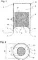
- Figures 1 and 2show a first embodiment of the packaging in accordance with the invention.
- the packagingcomprises a first end, a second end complete with a end-wall, a cylindrical (rounded) wall 4, which encloses a volume area 5 to comprise a stack 12 of flat, flexible and absorbing articles 10.
- the end-wall 3covers an aperture 6 for withdrawal of the articles 10.
- the aperture 6has a dimension d, in the shown embodiment a diameter of a circular aperture, where the dimension d is less than that of the articles' dimension D in the same direction.
- the stack of articles 12lie with the outermost article 11 against the end wall 3 and are retained by this.
- the outermost article 11is, however, accessible for withdrawal through aperture 6.
- the articles 10can easily be withdrawn one by one by grabbing the outermost article and withdrawing this through aperture 6.
- the rounded wall 4is extended outwards over the aperture 6's level so as to form supporting devices 8.
- the packagingrests only on supporting points 7 by the supporting devices 8's end.
- the aperture 6is elevated above the supporting surface such that articles 10, and especially the outermost article 11, do not come into contact with soil or fluids on the supporting surface.
- Another advantage with this embodimentis that the packaging's contact with the supporting surface is reduced to a straight supporting face.
- the packaginghas an advantageous cross section, which is adapted to the articles' dimensions and shape, which in the embodiment of figures 1 and 2 is a round shaped end-wall cross section, which can have another arbitrary geometric shape such as an ellipse or an enclosed polygon. Furthermore, an aperture 6 assumes any shape what-so-ever as long as the conditions are fulfilled so that the aperture 6's dimensions d is less than those of the articles' dimensions D in the same direction.
- Fig. 3shows a specifically advantageous embodiment in accordance with the invention where the article stack 12 is in contact towards the aperture 6's end-wall by the aid of an advancing system.
- the advancing systemis shaped as an intermediate base 14, which is forced against the article stack's ends that faces away from the aperture by the aid of elastic elements such as springs 15, which connect the intermediate base 14 with the rest of the packaging.
- the spring 15is a spring-loaded device positioned between the intermediate base 14 and, for this packaging, the associated end-wall 18. The spring 15 is tensioned when filling with articles 10, and the article stack is thus brought into contact with aperture 6.
- the aperturescan be held closed with thin foil which can be held in place with an attached lid, which is adjacent to the end-wall 3's side, which faces outwards (is not shown in the drawings).
- the packagingcan include a lid 16 which, during transport, is fitted on the packaging's second end 2 so as to protect the outermost article 11, and which is demountable and possibly can be fitted on the packaging's first end 1, as shown in fig. 3 .
- Fig. 4 - fig. 6shows an alternative embodiment for the packaging in accordance to the invention.
- the packagingis constructed as a tube, where the rounded wall 104 is a tube with a significant elliptical cross section with a small main axis and a larger main axis.
- the packagingis filled with folded articles 110 as shown in fig. 5 , and the packaging is thereafter closed at its first end 101 by permanently squeezing the rounded wall 104, for example by rabbeting, welding or adhesion.
- the other end, 102covers the end-wall 103 with its slit-formed aperture 106.
- the aperture 106's dimensions d and the folded articles 110's dimensions D in the same directionis measured, as shown in fig.
- the aperture 106 and thus the whole article stack 112is elevated above the supporting face by the aid of the supporting device 108, which in the fig. 4 - fig. 6 shown embodiments is developed as leg 117 forming an extension of the rounded wall 104 towards the end-wall 103.
- the supporting devices 108By forming the supporting devices 108 as a leg 117 another advantage is attained as the packaging's contact with the supporting surface is reduced to few resting points 107 without influencing the stability. On the contrary, a packaging standing only on a number of legs 117 and resting on a number of resting points is even more steady on uneven surfaces.
- a damp environmentcan occur within the space internally in the packaging surrounded by the supporting face as well as the supporting devices 108, the end-wall 103 and the outermost article 111.
- the supporting devices 108can be developed with ventilation apertures 109 in the form of holes in the side and/or as an intermediate space between the legs 117.
Landscapes
- Health & Medical Sciences (AREA)
- Engineering & Computer Science (AREA)
- Mechanical Engineering (AREA)
- General Health & Medical Sciences (AREA)
- Heart & Thoracic Surgery (AREA)
- Vascular Medicine (AREA)
- Life Sciences & Earth Sciences (AREA)
- Animal Behavior & Ethology (AREA)
- Biomedical Technology (AREA)
- Public Health (AREA)
- Veterinary Medicine (AREA)
- Epidemiology (AREA)
- Packaging Of Annular Or Rod-Shaped Articles, Wearing Apparel, Cassettes, Or The Like (AREA)
- Packages (AREA)
- Absorbent Articles And Supports Therefor (AREA)
- Buffer Packaging (AREA)
Description
- The invention relates to a packaging for stacking of absorbing materials such as cotton wool tampons and such hygiene articles. The packaging consists of (1) a first end, (2) a second end and (3) a closure face and (4) a cylindrical (rounded) side wall which embodies a storage for the articles and which also connects the first end and the second end to the final closure face and thus enabling the withdrawal of one article at a time. The aperture on at least one side is smaller than the withdrawn article in the same direction, whilst the second end encounters the resting-points that define a resting surface to support the packaging on its supporting surface. The aperture can be re-closed as of free choice.
- A packaging of a stackedcotton wool tampons is known from
US 1,890,295 A . This packaging is suitable for transport of cotton wool tampons from the production line to retailers and further to the end users and protects the tampons against dust and spray from an area above after the packaging is opened. In connection with the withdrawal (dispensing) of the tampons this packaging includes an aperture, which faces the support face, which also can be closed by a flap, hinged to the underside of the packaging. FR 1 552 648 A1- The drawback of these types of packagings is that the aperture for removal of the articles is situated on the end face of the packaging, which also forms the supporting platform. Should these packages be placed on the supporting platform such that the end wall with its aperture faces downwards so as to avoid soiling and spray from above, this will enable the end wall to be subject to soil and moisture that is situated below the supporting platform level and thus enabling these impurities to enter the packaging and damage the contents of the packaging.
US 6,588,626 discloses a packaging comprising a first space containing the absorbing material, and a second space, which is situated below the first space. Thus, the first space is elevated above the supporting surface so as to protect this from puddles of water on the supporting surface. The aperture for dispensing the articles is situated in the compartment wall and the articles are therefore not protected in the same way against soil and spray.US 2005 276653 A1 discloses a dispensing device with a container for dispensing stacked commercial sample single dose cosmetic applicators through an aperture at its bottom. The cosmetic applicators comprise a flat applicator portion and a grasping element or handle containing the sample and positioned perpendicularly to the flat applicator portion when stacked inside the packaging. The packaging comprises a supporting structure connected to the bottom of the container. The supporting structure is in the form of a large foot comprised of a sheet of material, which has been bent twice to form an inverted U-shape. The grasping element extends out of a bottom aperture such that a cosmetic applicator can be withdrawn by pulling the grasping element.WO 00/01271 A1 claim 1.- The aim of the invention is to produce a packaging for a stack of absorbing materials, such as cotton wool tampons or similar hygiene articles, where the packaging protects the articles against soil and spray from above and the sides as well as prohibits contamination from below and also from the supporting surface. A further purpose is to enable articles to be withdrawn from the packaging one by one.
- Another aim of this invention is to produce a packaging with sufficient ventilation in the vicinity around the outmost article, which is not protected by the end walls, and so to eliminate biological contamination in the form of mould and bacterial cultures.
- To achieve the above mentioned objects, the device according to the invention is characterized by the features of
claim 1. Advantageous embodiments are defined in dependent claims 2-10. - By means of the supporting means the end wall aperture is elevated above the supporting surface and thereby limits the packaging contact area of the part of the packaging, which contains the articles, and thus avoid that any fluids in the vicinity of the supporting surface enter the packaging, damaging this or the contents.
- The end with the aperture covers the packaging resting points on which the package can stand. The resting points can at least be three, a rounded edge or comprise one or more surfaces. The resting points are levelled with each other and define the resting surface. When the packaging stands upon the resting surface it then, at all times, supports the packaging's point of gravity.
- The second end of the packaging, in comparison to the end wall, forms a resting surface for the protruding support devices of which the resting points, that lie within an outward going distance to the end walls aperture. When the packaging is standing on the resting surface, the aperture faces downwards and is raised higher than the supporting surface. By this, the articles, and especially the outermost article, are protected against dust, soil and spray from above as well as avoiding contact with the supporting surface and soil and moist that can be on the supporting surface.
- In accordance with the invention, the packaging is mainly formed as a container of a stiff or semi stiff material such as cardboard, plastic or metal. The rounded surface of the packaging is formed as a tube, which embodies and holds the stack of articles. It is advantageous that the tube has body dimensions that fit the articles' dimensions and form - but can, however, have any other geometric shape. The material should be suitable for eliminating dust and spray - but, as a result of the special construction, which will reduce the packaging contact with the surface, need not be able to sustain continued contact with water other places than the packaging resting points.
- This means that the packaging design can have a greater freedom in choice of materials and construction. In a preferred embodiment this can be produced as single use packaging. The packaging can be filled during production and be finally sealed at the first end by folding, heating, welding or adhesion methods or by fitting an end wall. In specific cases, where reusable packaging is used, the packaging's first end can be closed with a removable flap cover allowing refilling.
- Basically, the articles can be removed from the packaging in two directions. A radial direction, which is substantially at a 90-degree angle to the axis of the stack or an axial direction, that is substantially parallel to the axis of the stack. In a preferable embodiment the packaging longitudinal axis, which runs from the first to the second end of the packaging, will extend in a parallel axis so that the articles can be withdrawn one by one in that direction.
- According to the invention, and in an advantageous embodiment, the supporting device is formed by an elongation of the packaging's circular wall. In this way, the supporting devices can easily be produced at low cost.
- When in use in a moist environment it is advantageous that the supporting devices include ventilation openings that permit airflow so as to avoid formation of mould within the area that is enclosed by the packaging's outer wall, the supporting device and the supporting surface.
- In an advantageous embodiment the resting points form a straight line. The packaging rests steadily on this closed line, which forms the resting surface. This will reduce the possibility of water damage to the packaging as contact with the supporting surface.
- In another embodiment the supporting devices are formed as a number consisting of at least three legs. By this, the packaging rests only on a few points and thus further reduces the possibility of the supporting surface being damaged by fluids. Furthermore, the packaging will be less sensitive to uneven supporting surfaces, thus making the packaging even steadier.
- The articles can be forced towards the aperture simply by the weight of the stack of articles, but will mainly be led to this with the aid of an advancing device. I an advantageous embodiment, the advancing device would be formed by the help of an intermediate base, which lies towards the end of the article stack opposite the aperture and thus presses against the opposite end. The thrust force can be attained by attaching the intermediate base to the packaging by the aid of elastic elements, which can be pre-tensioned at the filling stage so that the intermediate base and the stack of articles are forced or drawn to the aperture and thereby brought into contact towards the aperture in the end wall. In accordance with the invention, alternative embodiments such as "screw" devices as known from for example lipsticks, can be implemented.
- The invention is explained below with reference to the drawings. In the drawings the following is shown:
Fig. 1 - A first embodiment of a packaging in accordance with the invention.Fig. 2 - The packaging in accordance withfig. 1 and as seen from below.Fig. 3 - The packaging in accordance withfig. 1 showing the spring-loaded intermediate base.Fig. 4 - An alternative embodiment seen from the front of a packaging in accordance with the invention as a tube.Fig. 5 - The packaging in accordance withfig. 4 seen from the side and in cross section.- Fig. 6 - The packaging in accordance with
fig. 4 seen from below. Figures 1 and 2 show a first embodiment of the packaging in accordance with the invention. The packaging comprises a first end, a second end complete with a end-wall, a cylindrical (rounded)wall 4, which encloses avolume area 5 to comprise astack 12 of flat, flexible and absorbingarticles 10. The end-wall 3 covers anaperture 6 for withdrawal of thearticles 10. Theaperture 6 has a dimension d, in the shown embodiment a diameter of a circular aperture, where the dimension d is less than that of the articles' dimension D in the same direction. The stack ofarticles 12 lie with theoutermost article 11 against theend wall 3 and are retained by this. Theoutermost article 11 is, however, accessible for withdrawal throughaperture 6. Thearticles 10 can easily be withdrawn one by one by grabbing the outermost article and withdrawing this throughaperture 6.- The
rounded wall 4 is extended outwards over theaperture 6's level so as to form supportingdevices 8. When the packaging is placed on a supporting surface withaperture 6 in theend wall 3 facing downwards, the packaging rests only on supportingpoints 7 by the supportingdevices 8's end. Theaperture 6 is elevated above the supporting surface such thatarticles 10, and especially theoutermost article 11, do not come into contact with soil or fluids on the supporting surface. Another advantage with this embodiment is that the packaging's contact with the supporting surface is reduced to a straight supporting face. - The packaging has an advantageous cross section, which is adapted to the articles' dimensions and shape, which in the embodiment of
figures 1 and 2 is a round shaped end-wall cross section, which can have another arbitrary geometric shape such as an ellipse or an enclosed polygon. Furthermore, anaperture 6 assumes any shape what-so-ever as long as the conditions are fulfilled so that theaperture 6's dimensions d is less than those of the articles' dimensions D in the same direction. Fig. 3 shows a specifically advantageous embodiment in accordance with the invention where thearticle stack 12 is in contact towards theaperture 6's end-wall by the aid of an advancing system. In the shown embodiment the advancing system is shaped as anintermediate base 14, which is forced against the article stack's ends that faces away from the aperture by the aid of elastic elements such assprings 15, which connect theintermediate base 14 with the rest of the packaging. In the shown embodiment thespring 15 is a spring-loaded device positioned between theintermediate base 14 and, for this packaging, the associated end-wall 18. Thespring 15 is tensioned when filling witharticles 10, and the article stack is thus brought into contact withaperture 6. So as to protect theoutermost articles 11 during transport the apertures can be held closed with thin foil which can be held in place with an attached lid, which is adjacent to the end-wall 3's side, which faces outwards (is not shown in the drawings). Alternatively, or as a supplement, the packaging can include alid 16 which, during transport, is fitted on the packaging's second end 2 so as to protect theoutermost article 11, and which is demountable and possibly can be fitted on the packaging'sfirst end 1, as shown infig. 3 .Fig. 4 - fig. 6 shows an alternative embodiment for the packaging in accordance to the invention. The packaging is constructed as a tube, where therounded wall 104 is a tube with a significant elliptical cross section with a small main axis and a larger main axis. The packaging is filled with foldedarticles 110 as shown infig. 5 , and the packaging is thereafter closed at itsfirst end 101 by permanently squeezing therounded wall 104, for example by rabbeting, welding or adhesion. The other end, 102, covers the end-wall 103 with its slit-formedaperture 106. Theaperture 106's dimensions d and the foldedarticles 110's dimensions D in the same direction is measured, as shown infig. 5 , in parallel with the ellipse's small main axis. Thearticles 110 press against theaperture 106 on account of the weight and their elasticity, which seeks to elongate each article in a single level. When theoutermost article 111 is withdrawn throughaperture 106, the following article is drawn towards the aperture as a result of the friction between thearticles 110 supported by the above-mentioned elasticity force that seeks to stretch each article to a single level.- When the packaging is placed vertically in the resting points 107, the
aperture 106 and thus thewhole article stack 112 is elevated above the supporting face by the aid of the supportingdevice 108, which in thefig. 4 - fig. 6 shown embodiments is developed asleg 117 forming an extension of therounded wall 104 towards the end-wall 103. By forming the supportingdevices 108 as aleg 117 another advantage is attained as the packaging's contact with the supporting surface is reduced to few restingpoints 107 without influencing the stability. On the contrary, a packaging standing only on a number oflegs 117 and resting on a number of resting points is even more steady on uneven surfaces. - In case of there being fluids on the resting surface, a damp environment can occur within the space internally in the packaging surrounded by the supporting face as well as the supporting
devices 108, the end-wall 103 and theoutermost article 111. In such damp environments there is a danger of formation of mould and bacterial cultures or other types of biological contamination. So as to avoid accumulation of humid environments in contact with theoutermost articles 111 the supportingdevices 108 can be developed withventilation apertures 109 in the form of holes in the side and/or as an intermediate space between thelegs 117. - 1, 101 The packaging's first end
- 2, 102 The packaging's second end
- 3, 103 End-wall
- 4, 104 Rounded wall
- 5, 105 The packaging's internal volume
- 6, 106 Aperture
- 7, 107 Resting points
- 8, 108 Supporting devices
- 10, 110 Articles
- 11, 111 Outermost article
- 12, 112 Article stack
- 13, Article stack axis
- 14, Intermediate base
- 15, Spring
- 16, Cover
- 18, End-wall at packaging's
first end - 109, Ventilation opening
- 117, Leg
- d,
Apertures 61, 106 dimension - D,
Articles
Claims (10)
- A dispensing device for flat, flexible, absorbing articles (10, 110), more specifically cotton wool tampons or cotton pads, adapted for withdrawing such articles one by one,
said device comprising an enclosing wall (4, 104) defining an internal volume (5, 105) containing a number of said articles (10, 110) stacked with flat surfaces abutting each other in a longitudinal dimension of said volume (5, 105), said longitudinal direction being perpendicular to a cross-sectional dimension,
said volume (5, 105) terminating in said longitudinal dimension at a first, closed end (1, 101) and at an opposite, second end (2, 102), said second end (2, 102) comprising an end wall (3, 103) with an aperture (6, 106) for withdrawing an outermost article, a cross-sectional dimension (d) of said aperture (6, 106) being less than a cross-sectional dimension (D) of said stacked articles (10, 110) such as to allow for withdrawing one of said articles (10, 110) nearest to said aperture (6, 106) through said aperture (6, 106) by means of deformation of said article (10, 110),
characterized by further comprising
a supporting structure (8, 108) being positioned near said second end (2, 102) and comprising protruding resting points (7, 107) defining a plane for supporting the device in an upright position on a supporting face such as to position said end wall (3, 103) at a distance from said supporting face, said supporting structure (8, 108) comprising at least one opening or cut-out adapted to allow for withdrawing said outermost article through said aperture (106) and, subsequently, through said opening or cut-out,
said supporting structure (8, 108) having cross-sectional dimensions, which are substantially identical to cross-sectional dimensions of said volume (5, 105) at said second end (2, 102) of said volume (5, 105), said supporting structure (8, 108) forming a uniform continuation of said enclosing wall (4, 104), which continuation extends in said longitudinal dimension. - A device according to claim 1, wherein said supporting structure (8, 108) is an extension of and is formed integrally with said enclosing wall (4, 104).
- A device according to claim 1 or 2, wherein said supporting structure (8, 108) is shaped as a wall, which at a distal end is open such as to define an aperture extending in said cross-sectional dimension.
- A device according to claim 3, wherein a preferably rounded cut-out of said supporting structure wall extends in said longitudinal dimension from said distal end of said supporting structure wall.
- A device according to any one of the previous claims, wherein said supporting structure (8, 108) comprises at least three legs, each of said legs forming one said resting point (7, 107).
- A device according to any one of the previous claims, wherein said device is cylindrical with a round shape, such as circular or ellipse-shaped, in cross-section.
- A device according to any one of the previous claims, wherein said end wall (3, 103) extends in said cross-sectional dimension.
- A device according to any one of the previous claims, wherein said supporting structure (8, 108) comprises ventilation holes.
- A device according to any one of the previous claims, wherein said resting points (7, 107) form an unbroken line.
- A device according to any one of the previous claims, further comprising means for advancing said stack of articles (10, 110) towards said aperture (6, 106) by means of elastic elements such as springs.
Applications Claiming Priority (2)
| Application Number | Priority Date | Filing Date | Title |
|---|---|---|---|
| DK200600918ADK176445B1 (en) | 2006-07-04 | 2006-07-04 | Vatrondelholder |
| PCT/DK2007/000331WO2008003316A1 (en) | 2006-07-04 | 2007-07-03 | Cotton wool pad dispenser |
Publications (3)
| Publication Number | Publication Date |
|---|---|
| EP2054319A1 EP2054319A1 (en) | 2009-05-06 |
| EP2054319A4 EP2054319A4 (en) | 2014-12-03 |
| EP2054319B1true EP2054319B1 (en) | 2018-06-13 |
Family
ID=38894213
Family Applications (1)
| Application Number | Title | Priority Date | Filing Date |
|---|---|---|---|
| EP07764461.5AActiveEP2054319B1 (en) | 2006-07-04 | 2007-07-03 | Cotton wool pad dispenser |
Country Status (10)
| Country | Link |
|---|---|
| US (1) | US8152022B2 (en) |
| EP (1) | EP2054319B1 (en) |
| JP (2) | JP4768853B2 (en) |
| KR (1) | KR101074142B1 (en) |
| CN (1) | CN101484369B (en) |
| CA (1) | CA2655678C (en) |
| DK (2) | DK176445B1 (en) |
| NO (1) | NO341854B1 (en) |
| RU (1) | RU2415794C2 (en) |
| WO (1) | WO2008003316A1 (en) |
Families Citing this family (15)
| Publication number | Priority date | Publication date | Assignee | Title |
|---|---|---|---|---|
| DK176445B1 (en) | 2006-07-04 | 2008-02-25 | Anne-Mette Ju Nygaard-Petersen | Vatrondelholder |
| SG188453A1 (en)* | 2010-09-10 | 2013-05-31 | Eazy Pac Danmark As | A cotton pad dispenser and a method for its production |
| GB2518519A (en) | 2012-07-03 | 2015-03-25 | Ds Smith Packaging Ltd | Corrugated pusher |
| GB2508808B (en)* | 2012-11-06 | 2015-09-02 | Kraft Foods Uk R & D Ltd | Pusher |
| CN109890712B (en) | 2016-11-01 | 2021-08-06 | 卡夫食品瑞士控股有限责任公司 | Integrated traction system with rear flap |
| EP3625135B1 (en)* | 2017-05-16 | 2021-07-28 | Intercontinental Great Brands LLC | A package for displaying items |
| CN108750483B (en)* | 2018-06-27 | 2021-09-14 | 通慧达(南京)智能科技有限公司 | Can collect multi-functional for scenic spot indicating device of rubbish |
| CN110182451A (en)* | 2019-05-24 | 2019-08-30 | 南京双路智能科技有限公司 | A kind of electronic memory access of sheet solid-state food based on Double-linkage notch |
| US11532197B2 (en)* | 2019-08-09 | 2022-12-20 | Aunt Flow Corp. | Product dispensing system |
| USD1015770S1 (en)* | 2020-10-22 | 2024-02-27 | Corey L. Egleston | Spring loaded disposable glove dispenser |
| US11395775B1 (en) | 2021-05-12 | 2022-07-26 | Jonathan Temple | Pad storage and dispensing device |
| US12101284B2 (en) | 2021-11-29 | 2024-09-24 | Virtual Connect Technoloties, Inc. | Computerized system for analysis of vertices and edges of an electronic messaging system |
| RU210438U1 (en)* | 2021-12-07 | 2022-04-15 | Евгений Юрьевич Андрианов | Semi-automatic cotton pad dispenser |
| US11916873B1 (en) | 2022-08-15 | 2024-02-27 | Virtual Connect Technologies, Inc. | Computerized system for inserting management information into electronic communication systems |
| CN116946568A (en)* | 2023-08-28 | 2023-10-27 | 成都禾想医疗科技有限公司 | Probe isolating membrane group material box |
Family Cites Families (31)
| Publication number | Priority date | Publication date | Assignee | Title |
|---|---|---|---|---|
| US1702573A (en)* | 1924-11-25 | 1929-02-19 | Individ Ual Drinking Cup Compa | Cup holding and dispensing device |
| US1890295A (en)* | 1932-04-30 | 1932-12-06 | A J Donahue Corp | Dispensing-package for powder puffs |
| US2115923A (en)* | 1936-11-05 | 1938-05-03 | Cooper Felix | Dispenser for tea bags |
| US2365916A (en)* | 1941-06-20 | 1944-12-26 | Lily Tulip Cup Corp | Mechanism for dispensing cups or the like |
| US3246800A (en)* | 1964-07-02 | 1966-04-19 | Developak Inc | Dispensing container for receptacles |
| FR1552684A (en)* | 1967-02-09 | 1969-01-03 | ||
| US3669307A (en)* | 1970-11-06 | 1972-06-13 | Sobel Ind | Plastic cup dispenser |
| US4053242A (en)* | 1976-03-18 | 1977-10-11 | The Procter & Gamble Company | Disposable product applicator and dispensing package therefor |
| CA1070272A (en)* | 1977-11-07 | 1980-01-22 | Ronald G. Harrison | Dispenser for plastic cards |
| CH679574A5 (en) | 1989-07-28 | 1992-03-13 | Flawa Schweiz Verband Wattefab | |
| CN2105471U (en)* | 1991-08-30 | 1992-05-27 | 周全荣 | Drug sensitive paper distributing pipe |
| DE4214649B4 (en) | 1992-05-02 | 2004-08-26 | The Procter & Gamble Company, Cincinnati | Foil bags for hygiene articles |
| US5301833A (en)* | 1992-12-18 | 1994-04-12 | Erkin Aycan | Liquid dispenser with cup holder |
| US5685643A (en)* | 1993-02-26 | 1997-11-11 | Vp-Schickedanz Sa | Plastic bag for personal-hygiene articles |
| DE4317611A1 (en)* | 1993-05-27 | 1995-01-05 | Vp Schickedanz S A | Foil tubular bag for holding hygiene articles and process for its manufacture |
| US5501365A (en)* | 1994-03-25 | 1996-03-26 | Playtex Products, Inc. | Package and system for dispensing preformed nurser sacs |
| JPH08276938A (en) | 1995-03-31 | 1996-10-22 | Nichiban Co Ltd | Suspension cylindrical package body for bandage or the like |
| DE29508539U1 (en)* | 1995-05-23 | 1995-09-28 | Huisman, Ronald, Bussum | Eating device for holding pieces of food as well as a combination of a dispenser and eating devices held in it |
| US6109787A (en)* | 1995-10-13 | 2000-08-29 | Procter & Gamble | Soft bag for personal-hygiene articles |
| US5632409A (en)* | 1995-10-20 | 1997-05-27 | Raghunanan; Cheryl J. | Plastic bag holder |
| FR2749151B1 (en) | 1996-05-30 | 1998-08-21 | Gandois Jean Marie | DISPOSABLE PAD BOX FOR FOOTWEAR CLEANING |
| RU2123464C1 (en)* | 1997-06-06 | 1998-12-20 | Жерновский Александр Владимирович | Device for storing and item-by-item discharge of tablets (design versions) |
| US6419113B1 (en)* | 1997-12-16 | 2002-07-16 | Kimberly-Clark Worldwide, Inc. | Cartridge for dispensing paper products |
| US6523717B1 (en)* | 1998-07-07 | 2003-02-25 | Weasy Pack B.V. | Apparatus for dispensing a porous carrier |
| DE19852297A1 (en) | 1998-11-12 | 2000-05-18 | Rauscher & Co | Device for providing hygiene articles |
| US6588626B2 (en)* | 2000-11-30 | 2003-07-08 | Kimberly-Clark Worldwide, Inc. | Optionally hangable container and dispensing method |
| US6799695B1 (en)* | 2002-04-02 | 2004-10-05 | Miguel Borrero | Sanitary napkin dispensing device |
| US6789697B2 (en)* | 2002-08-14 | 2004-09-14 | Traex Company | Adjustable cup dispenser |
| DE202004000696U1 (en) | 2004-01-16 | 2005-05-25 | Emsa-Werke Wulf Gmbh & Co. Kg | Dispensing container especially for stackable flat-form objects has intermediate bottom connected to at least one operating element by at least one draw band guided into container body in upper edge region and then reversed there |
| FR2871145B1 (en)* | 2004-06-08 | 2006-08-18 | Oreal | DISTRIBUTOR OF APPLICATORS |
| DK176445B1 (en) | 2006-07-04 | 2008-02-25 | Anne-Mette Ju Nygaard-Petersen | Vatrondelholder |
- 2006
- 2006-07-04DKDK200600918Apatent/DK176445B1/enactive
- 2007
- 2007-07-03JPJP2009516902Apatent/JP4768853B2/enactiveActive
- 2007-07-03EPEP07764461.5Apatent/EP2054319B1/enactiveActive
- 2007-07-03CNCN2007800253268Apatent/CN101484369B/enactiveActive
- 2007-07-03KRKR1020097002250Apatent/KR101074142B1/enactiveActive
- 2007-07-03DKDK07764461.5Tpatent/DK2054319T3/enactive
- 2007-07-03USUS12/307,302patent/US8152022B2/enactiveActive
- 2007-07-03CACA2655678Apatent/CA2655678C/enactiveActive
- 2007-07-03WOPCT/DK2007/000331patent/WO2008003316A1/enactiveApplication Filing
- 2007-07-03RURU2009103624/12Apatent/RU2415794C2/ennot_activeApplication Discontinuation
- 2009
- 2009-02-04NONO20090544Apatent/NO341854B1/enunknown
- 2011
- 2011-06-16JPJP2011134548Apatent/JP4843113B2/enactiveActive
Non-Patent Citations (1)
| Title |
|---|
| None* |
Also Published As
| Publication number | Publication date |
|---|---|
| EP2054319A4 (en) | 2014-12-03 |
| JP2011207534A (en) | 2011-10-20 |
| DK200600918A (en) | 2008-01-05 |
| JP2009541164A (en) | 2009-11-26 |
| CN101484369B (en) | 2013-05-01 |
| DK176445B1 (en) | 2008-02-25 |
| CA2655678C (en) | 2012-10-16 |
| EP2054319A1 (en) | 2009-05-06 |
| RU2415794C2 (en) | 2011-04-10 |
| JP4843113B2 (en) | 2011-12-21 |
| CA2655678A1 (en) | 2008-01-10 |
| DK2054319T3 (en) | 2018-09-03 |
| KR20090040313A (en) | 2009-04-23 |
| KR101074142B1 (en) | 2011-10-18 |
| NO20090544L (en) | 2009-02-04 |
| NO341854B1 (en) | 2018-02-05 |
| WO2008003316A1 (en) | 2008-01-10 |
| CN101484369A (en) | 2009-07-15 |
| US8152022B2 (en) | 2012-04-10 |
| JP4768853B2 (en) | 2011-09-07 |
| RU2009103624A (en) | 2010-08-10 |
| US20090302051A1 (en) | 2009-12-10 |
Similar Documents
| Publication | Publication Date | Title |
|---|---|---|
| EP2054319B1 (en) | Cotton wool pad dispenser | |
| KR101195554B1 (en) | Wet and dry towel dispenser | |
| US8695848B2 (en) | Angled tissue carton | |
| US9586743B2 (en) | Hanging bag | |
| US20070062967A1 (en) | System, container, pack and method for packing and dispensing wipes | |
| EP3079547B1 (en) | Dispenser for interfolded napkins | |
| US7533846B2 (en) | Towel roll product with supportive, protective wrapper | |
| US20090200328A1 (en) | Wipes Canister | |
| US20090188936A1 (en) | Chip Dispensing Container | |
| RU2712429C2 (en) | Glove dispenser | |
| WO2013057565A2 (en) | Portable sheet product dispenser | |
| JP2024061040A (en) | Liquid storing tool | |
| US20070262085A1 (en) | Nesting tissue carton | |
| US20080296178A1 (en) | Package for Distributing and Storing a Plurality of Sanitary Products | |
| WO2006135563A2 (en) | Package for storing used and unused disposable cleaning products |
Legal Events
| Date | Code | Title | Description |
|---|---|---|---|
| PUAI | Public reference made under article 153(3) epc to a published international application that has entered the european phase | Free format text:ORIGINAL CODE: 0009012 | |
| 17P | Request for examination filed | Effective date:20090122 | |
| AK | Designated contracting states | Kind code of ref document:A1 Designated state(s):AT BE BG CH CY CZ DE DK EE ES FI FR GB GR HU IE IS IT LI LT LU LV MC MT NL PL PT RO SE SI SK TR | |
| AX | Request for extension of the european patent | Extension state:AL BA HR MK RS | |
| DAX | Request for extension of the european patent (deleted) | ||
| A4 | Supplementary search report drawn up and despatched | Effective date:20141104 | |
| RIC1 | Information provided on ipc code assigned before grant | Ipc:B65D 83/08 20060101AFI20141029BHEP Ipc:A61F 15/00 20060101ALI20141029BHEP | |
| GRAP | Despatch of communication of intention to grant a patent | Free format text:ORIGINAL CODE: EPIDOSNIGR1 | |
| INTG | Intention to grant announced | Effective date:20151103 | |
| 17Q | First examination report despatched | Effective date:20160607 | |
| INTC | Intention to grant announced (deleted) | ||
| GRAP | Despatch of communication of intention to grant a patent | Free format text:ORIGINAL CODE: EPIDOSNIGR1 | |
| INTG | Intention to grant announced | Effective date:20171017 | |
| GRAJ | Information related to disapproval of communication of intention to grant by the applicant or resumption of examination proceedings by the epo deleted | Free format text:ORIGINAL CODE: EPIDOSDIGR1 | |
| INTC | Intention to grant announced (deleted) | ||
| GRAR | Information related to intention to grant a patent recorded | Free format text:ORIGINAL CODE: EPIDOSNIGR71 | |
| GRAS | Grant fee paid | Free format text:ORIGINAL CODE: EPIDOSNIGR3 | |
| GRAA | (expected) grant | Free format text:ORIGINAL CODE: 0009210 | |
| AK | Designated contracting states | Kind code of ref document:B1 Designated state(s):AT BE BG CH CY CZ DE DK EE ES FI FR GB GR HU IE IS IT LI LT LU LV MC MT NL PL PT RO SE SI SK TR | |
| INTG | Intention to grant announced | Effective date:20180508 | |
| REG | Reference to a national code | Ref country code:GB Ref legal event code:FG4D | |
| REG | Reference to a national code | Ref country code:CH Ref legal event code:EP Ref country code:AT Ref legal event code:REF Ref document number:1008268 Country of ref document:AT Kind code of ref document:T Effective date:20180615 | |
| REG | Reference to a national code | Ref country code:DE Ref legal event code:R096 Ref document number:602007055105 Country of ref document:DE | |
| REG | Reference to a national code | Ref country code:IE Ref legal event code:FG4D | |
| REG | Reference to a national code | Ref country code:FR Ref legal event code:PLFP Year of fee payment:12 | |
| REG | Reference to a national code | Ref country code:DK Ref legal event code:T3 Effective date:20180829 | |
| REG | Reference to a national code | Ref country code:NL Ref legal event code:MP Effective date:20180613 | |
| REG | Reference to a national code | Ref country code:LT Ref legal event code:MG4D | |
| PG25 | Lapsed in a contracting state [announced via postgrant information from national office to epo] | Ref country code:CY Free format text:LAPSE BECAUSE OF FAILURE TO SUBMIT A TRANSLATION OF THE DESCRIPTION OR TO PAY THE FEE WITHIN THE PRESCRIBED TIME-LIMIT Effective date:20180613 Ref country code:SE Free format text:LAPSE BECAUSE OF FAILURE TO SUBMIT A TRANSLATION OF THE DESCRIPTION OR TO PAY THE FEE WITHIN THE PRESCRIBED TIME-LIMIT Effective date:20180613 Ref country code:ES Free format text:LAPSE BECAUSE OF FAILURE TO SUBMIT A TRANSLATION OF THE DESCRIPTION OR TO PAY THE FEE WITHIN THE PRESCRIBED TIME-LIMIT Effective date:20180613 Ref country code:LT Free format text:LAPSE BECAUSE OF FAILURE TO SUBMIT A TRANSLATION OF THE DESCRIPTION OR TO PAY THE FEE WITHIN THE PRESCRIBED TIME-LIMIT Effective date:20180613 Ref country code:FI Free format text:LAPSE BECAUSE OF FAILURE TO SUBMIT A TRANSLATION OF THE DESCRIPTION OR TO PAY THE FEE WITHIN THE PRESCRIBED TIME-LIMIT Effective date:20180613 Ref country code:BG Free format text:LAPSE BECAUSE OF FAILURE TO SUBMIT A TRANSLATION OF THE DESCRIPTION OR TO PAY THE FEE WITHIN THE PRESCRIBED TIME-LIMIT Effective date:20180913 | |
| PG25 | Lapsed in a contracting state [announced via postgrant information from national office to epo] | Ref country code:LV Free format text:LAPSE BECAUSE OF FAILURE TO SUBMIT A TRANSLATION OF THE DESCRIPTION OR TO PAY THE FEE WITHIN THE PRESCRIBED TIME-LIMIT Effective date:20180613 Ref country code:GR Free format text:LAPSE BECAUSE OF FAILURE TO SUBMIT A TRANSLATION OF THE DESCRIPTION OR TO PAY THE FEE WITHIN THE PRESCRIBED TIME-LIMIT Effective date:20180914 | |
| REG | Reference to a national code | Ref country code:AT Ref legal event code:MK05 Ref document number:1008268 Country of ref document:AT Kind code of ref document:T Effective date:20180613 | |
| PG25 | Lapsed in a contracting state [announced via postgrant information from national office to epo] | Ref country code:NL Free format text:LAPSE BECAUSE OF FAILURE TO SUBMIT A TRANSLATION OF THE DESCRIPTION OR TO PAY THE FEE WITHIN THE PRESCRIBED TIME-LIMIT Effective date:20180613 | |
| PG25 | Lapsed in a contracting state [announced via postgrant information from national office to epo] | Ref country code:AT Free format text:LAPSE BECAUSE OF FAILURE TO SUBMIT A TRANSLATION OF THE DESCRIPTION OR TO PAY THE FEE WITHIN THE PRESCRIBED TIME-LIMIT Effective date:20180613 Ref country code:SK Free format text:LAPSE BECAUSE OF FAILURE TO SUBMIT A TRANSLATION OF THE DESCRIPTION OR TO PAY THE FEE WITHIN THE PRESCRIBED TIME-LIMIT Effective date:20180613 Ref country code:EE Free format text:LAPSE BECAUSE OF FAILURE TO SUBMIT A TRANSLATION OF THE DESCRIPTION OR TO PAY THE FEE WITHIN THE PRESCRIBED TIME-LIMIT Effective date:20180613 Ref country code:PL Free format text:LAPSE BECAUSE OF FAILURE TO SUBMIT A TRANSLATION OF THE DESCRIPTION OR TO PAY THE FEE WITHIN THE PRESCRIBED TIME-LIMIT Effective date:20180613 Ref country code:IS Free format text:LAPSE BECAUSE OF FAILURE TO SUBMIT A TRANSLATION OF THE DESCRIPTION OR TO PAY THE FEE WITHIN THE PRESCRIBED TIME-LIMIT Effective date:20181013 Ref country code:CZ Free format text:LAPSE BECAUSE OF FAILURE TO SUBMIT A TRANSLATION OF THE DESCRIPTION OR TO PAY THE FEE WITHIN THE PRESCRIBED TIME-LIMIT Effective date:20180613 Ref country code:RO Free format text:LAPSE BECAUSE OF FAILURE TO SUBMIT A TRANSLATION OF THE DESCRIPTION OR TO PAY THE FEE WITHIN THE PRESCRIBED TIME-LIMIT Effective date:20180613 | |
| PG25 | Lapsed in a contracting state [announced via postgrant information from national office to epo] | Ref country code:IT Free format text:LAPSE BECAUSE OF FAILURE TO SUBMIT A TRANSLATION OF THE DESCRIPTION OR TO PAY THE FEE WITHIN THE PRESCRIBED TIME-LIMIT Effective date:20180613 | |
| REG | Reference to a national code | Ref country code:CH Ref legal event code:PL | |
| REG | Reference to a national code | Ref country code:DE Ref legal event code:R097 Ref document number:602007055105 Country of ref document:DE | |
| PG25 | Lapsed in a contracting state [announced via postgrant information from national office to epo] | Ref country code:LU Free format text:LAPSE BECAUSE OF NON-PAYMENT OF DUE FEES Effective date:20180703 Ref country code:MC Free format text:LAPSE BECAUSE OF FAILURE TO SUBMIT A TRANSLATION OF THE DESCRIPTION OR TO PAY THE FEE WITHIN THE PRESCRIBED TIME-LIMIT Effective date:20180613 | |
| REG | Reference to a national code | Ref country code:BE Ref legal event code:MM Effective date:20180731 | |
| REG | Reference to a national code | Ref country code:IE Ref legal event code:MM4A | |
| PLBE | No opposition filed within time limit | Free format text:ORIGINAL CODE: 0009261 | |
| STAA | Information on the status of an ep patent application or granted ep patent | Free format text:STATUS: NO OPPOSITION FILED WITHIN TIME LIMIT | |
| PG25 | Lapsed in a contracting state [announced via postgrant information from national office to epo] | Ref country code:IE Free format text:LAPSE BECAUSE OF NON-PAYMENT OF DUE FEES Effective date:20180703 Ref country code:LI Free format text:LAPSE BECAUSE OF NON-PAYMENT OF DUE FEES Effective date:20180731 Ref country code:CH Free format text:LAPSE BECAUSE OF NON-PAYMENT OF DUE FEES Effective date:20180731 | |
| 26N | No opposition filed | Effective date:20190314 | |
| PG25 | Lapsed in a contracting state [announced via postgrant information from national office to epo] | Ref country code:BE Free format text:LAPSE BECAUSE OF NON-PAYMENT OF DUE FEES Effective date:20180731 Ref country code:SI Free format text:LAPSE BECAUSE OF FAILURE TO SUBMIT A TRANSLATION OF THE DESCRIPTION OR TO PAY THE FEE WITHIN THE PRESCRIBED TIME-LIMIT Effective date:20180613 | |
| PG25 | Lapsed in a contracting state [announced via postgrant information from national office to epo] | Ref country code:MT Free format text:LAPSE BECAUSE OF NON-PAYMENT OF DUE FEES Effective date:20180703 | |
| PG25 | Lapsed in a contracting state [announced via postgrant information from national office to epo] | Ref country code:TR Free format text:LAPSE BECAUSE OF FAILURE TO SUBMIT A TRANSLATION OF THE DESCRIPTION OR TO PAY THE FEE WITHIN THE PRESCRIBED TIME-LIMIT Effective date:20180613 | |
| PG25 | Lapsed in a contracting state [announced via postgrant information from national office to epo] | Ref country code:PT Free format text:LAPSE BECAUSE OF FAILURE TO SUBMIT A TRANSLATION OF THE DESCRIPTION OR TO PAY THE FEE WITHIN THE PRESCRIBED TIME-LIMIT Effective date:20180613 Ref country code:HU Free format text:LAPSE BECAUSE OF FAILURE TO SUBMIT A TRANSLATION OF THE DESCRIPTION OR TO PAY THE FEE WITHIN THE PRESCRIBED TIME-LIMIT; INVALID AB INITIO Effective date:20070703 | |
| PGFP | Annual fee paid to national office [announced via postgrant information from national office to epo] | Ref country code:GB Payment date:20240618 Year of fee payment:18 | |
| PGFP | Annual fee paid to national office [announced via postgrant information from national office to epo] | Ref country code:DK Payment date:20240612 Year of fee payment:18 | |
| PGFP | Annual fee paid to national office [announced via postgrant information from national office to epo] | Ref country code:FR Payment date:20240618 Year of fee payment:18 | |
| PGFP | Annual fee paid to national office [announced via postgrant information from national office to epo] | Ref country code:DE Payment date:20240613 Year of fee payment:18 |