EP2054112B2 - Injection device with claw-type securing means - Google Patents
Injection device with claw-type securing meansDownload PDFInfo
- Publication number
- EP2054112B2 EP2054112B2EP07785091.5AEP07785091AEP2054112B2EP 2054112 B2EP2054112 B2EP 2054112B2EP 07785091 AEP07785091 AEP 07785091AEP 2054112 B2EP2054112 B2EP 2054112B2
- Authority
- EP
- European Patent Office
- Prior art keywords
- injection device
- threaded rod
- rotation
- ampoule
- thread
- Prior art date
- Legal status (The legal status is an assumption and is not a legal conclusion. Google has not performed a legal analysis and makes no representation as to the accuracy of the status listed.)
- Active
Links
Images


Classifications
- A—HUMAN NECESSITIES
- A61—MEDICAL OR VETERINARY SCIENCE; HYGIENE
- A61M—DEVICES FOR INTRODUCING MEDIA INTO, OR ONTO, THE BODY; DEVICES FOR TRANSDUCING BODY MEDIA OR FOR TAKING MEDIA FROM THE BODY; DEVICES FOR PRODUCING OR ENDING SLEEP OR STUPOR
- A61M5/00—Devices for bringing media into the body in a subcutaneous, intra-vascular or intramuscular way; Accessories therefor, e.g. filling or cleaning devices, arm-rests
- A61M5/178—Syringes
- A61M5/24—Ampoule syringes, i.e. syringes with needle for use in combination with replaceable ampoules or carpules, e.g. automatic
- A61M5/2448—Ampoule syringes, i.e. syringes with needle for use in combination with replaceable ampoules or carpules, e.g. automatic comprising means for injection of two or more media, e.g. by mixing
- A—HUMAN NECESSITIES
- A61—MEDICAL OR VETERINARY SCIENCE; HYGIENE
- A61M—DEVICES FOR INTRODUCING MEDIA INTO, OR ONTO, THE BODY; DEVICES FOR TRANSDUCING BODY MEDIA OR FOR TAKING MEDIA FROM THE BODY; DEVICES FOR PRODUCING OR ENDING SLEEP OR STUPOR
- A61M5/00—Devices for bringing media into the body in a subcutaneous, intra-vascular or intramuscular way; Accessories therefor, e.g. filling or cleaning devices, arm-rests
- A61M5/178—Syringes
- A61M5/31—Details
- A61M5/315—Pistons; Piston-rods; Guiding, blocking or restricting the movement of the rod or piston; Appliances on the rod for facilitating dosing ; Dosing mechanisms
- A61M5/31501—Means for blocking or restricting the movement of the rod or piston
- A—HUMAN NECESSITIES
- A61—MEDICAL OR VETERINARY SCIENCE; HYGIENE
- A61M—DEVICES FOR INTRODUCING MEDIA INTO, OR ONTO, THE BODY; DEVICES FOR TRANSDUCING BODY MEDIA OR FOR TAKING MEDIA FROM THE BODY; DEVICES FOR PRODUCING OR ENDING SLEEP OR STUPOR
- A61M5/00—Devices for bringing media into the body in a subcutaneous, intra-vascular or intramuscular way; Accessories therefor, e.g. filling or cleaning devices, arm-rests
- A61M5/178—Syringes
- A61M5/31—Details
- A61M5/315—Pistons; Piston-rods; Guiding, blocking or restricting the movement of the rod or piston; Appliances on the rod for facilitating dosing ; Dosing mechanisms
- A61M5/31533—Dosing mechanisms, i.e. setting a dose
- A61M5/31545—Setting modes for dosing
- A61M5/31548—Mechanically operated dose setting member
- A61M5/3155—Mechanically operated dose setting member by rotational movement of dose setting member, e.g. during setting or filling of a syringe
- A61M5/31553—Mechanically operated dose setting member by rotational movement of dose setting member, e.g. during setting or filling of a syringe without axial movement of dose setting member
- A—HUMAN NECESSITIES
- A61—MEDICAL OR VETERINARY SCIENCE; HYGIENE
- A61M—DEVICES FOR INTRODUCING MEDIA INTO, OR ONTO, THE BODY; DEVICES FOR TRANSDUCING BODY MEDIA OR FOR TAKING MEDIA FROM THE BODY; DEVICES FOR PRODUCING OR ENDING SLEEP OR STUPOR
- A61M5/00—Devices for bringing media into the body in a subcutaneous, intra-vascular or intramuscular way; Accessories therefor, e.g. filling or cleaning devices, arm-rests
- A61M5/178—Syringes
- A61M5/31—Details
- A61M5/315—Pistons; Piston-rods; Guiding, blocking or restricting the movement of the rod or piston; Appliances on the rod for facilitating dosing ; Dosing mechanisms
- A61M5/31565—Administration mechanisms, i.e. constructional features, modes of administering a dose
- A61M5/31576—Constructional features or modes of drive mechanisms for piston rods
- A61M5/31583—Constructional features or modes of drive mechanisms for piston rods based on rotational translation, i.e. movement of piston rod is caused by relative rotation between the user activated actuator and the piston rod
- A—HUMAN NECESSITIES
- A61—MEDICAL OR VETERINARY SCIENCE; HYGIENE
- A61M—DEVICES FOR INTRODUCING MEDIA INTO, OR ONTO, THE BODY; DEVICES FOR TRANSDUCING BODY MEDIA OR FOR TAKING MEDIA FROM THE BODY; DEVICES FOR PRODUCING OR ENDING SLEEP OR STUPOR
- A61M5/00—Devices for bringing media into the body in a subcutaneous, intra-vascular or intramuscular way; Accessories therefor, e.g. filling or cleaning devices, arm-rests
- A61M5/178—Syringes
- A61M5/31—Details
- A61M5/315—Pistons; Piston-rods; Guiding, blocking or restricting the movement of the rod or piston; Appliances on the rod for facilitating dosing ; Dosing mechanisms
- A61M5/31565—Administration mechanisms, i.e. constructional features, modes of administering a dose
- A61M5/3159—Dose expelling manners
- A61M5/31593—Multi-dose, i.e. individually set dose repeatedly administered from the same medicament reservoir
- A61M5/31595—Pre-defined multi-dose administration by repeated overcoming of means blocking the free advancing movement of piston rod, e.g. by tearing or de-blocking
- A—HUMAN NECESSITIES
- A61—MEDICAL OR VETERINARY SCIENCE; HYGIENE
- A61M—DEVICES FOR INTRODUCING MEDIA INTO, OR ONTO, THE BODY; DEVICES FOR TRANSDUCING BODY MEDIA OR FOR TAKING MEDIA FROM THE BODY; DEVICES FOR PRODUCING OR ENDING SLEEP OR STUPOR
- A61M5/00—Devices for bringing media into the body in a subcutaneous, intra-vascular or intramuscular way; Accessories therefor, e.g. filling or cleaning devices, arm-rests
- A61M5/178—Syringes
- A61M5/24—Ampoule syringes, i.e. syringes with needle for use in combination with replaceable ampoules or carpules, e.g. automatic
- A61M2005/2403—Ampoule inserted into the ampoule holder
- A61M2005/2407—Ampoule inserted into the ampoule holder from the rear
- A—HUMAN NECESSITIES
- A61—MEDICAL OR VETERINARY SCIENCE; HYGIENE
- A61M—DEVICES FOR INTRODUCING MEDIA INTO, OR ONTO, THE BODY; DEVICES FOR TRANSDUCING BODY MEDIA OR FOR TAKING MEDIA FROM THE BODY; DEVICES FOR PRODUCING OR ENDING SLEEP OR STUPOR
- A61M5/00—Devices for bringing media into the body in a subcutaneous, intra-vascular or intramuscular way; Accessories therefor, e.g. filling or cleaning devices, arm-rests
- A61M5/178—Syringes
- A61M5/24—Ampoule syringes, i.e. syringes with needle for use in combination with replaceable ampoules or carpules, e.g. automatic
- A61M5/2448—Ampoule syringes, i.e. syringes with needle for use in combination with replaceable ampoules or carpules, e.g. automatic comprising means for injection of two or more media, e.g. by mixing
- A61M2005/2451—Ampoule syringes, i.e. syringes with needle for use in combination with replaceable ampoules or carpules, e.g. automatic comprising means for injection of two or more media, e.g. by mixing preventing delivery before mixing is completed, e.g. by locking mechanisms
- A—HUMAN NECESSITIES
- A61—MEDICAL OR VETERINARY SCIENCE; HYGIENE
- A61M—DEVICES FOR INTRODUCING MEDIA INTO, OR ONTO, THE BODY; DEVICES FOR TRANSDUCING BODY MEDIA OR FOR TAKING MEDIA FROM THE BODY; DEVICES FOR PRODUCING OR ENDING SLEEP OR STUPOR
- A61M5/00—Devices for bringing media into the body in a subcutaneous, intra-vascular or intramuscular way; Accessories therefor, e.g. filling or cleaning devices, arm-rests
- A61M5/178—Syringes
- A61M5/24—Ampoule syringes, i.e. syringes with needle for use in combination with replaceable ampoules or carpules, e.g. automatic
- A61M2005/2485—Ampoule holder connected to rest of syringe
- A61M2005/2488—Ampoule holder connected to rest of syringe via rotation, e.g. threads or bayonet
- A—HUMAN NECESSITIES
- A61—MEDICAL OR VETERINARY SCIENCE; HYGIENE
- A61M—DEVICES FOR INTRODUCING MEDIA INTO, OR ONTO, THE BODY; DEVICES FOR TRANSDUCING BODY MEDIA OR FOR TAKING MEDIA FROM THE BODY; DEVICES FOR PRODUCING OR ENDING SLEEP OR STUPOR
- A61M5/00—Devices for bringing media into the body in a subcutaneous, intra-vascular or intramuscular way; Accessories therefor, e.g. filling or cleaning devices, arm-rests
- A61M5/178—Syringes
- A61M5/31—Details
- A61M5/315—Pistons; Piston-rods; Guiding, blocking or restricting the movement of the rod or piston; Appliances on the rod for facilitating dosing ; Dosing mechanisms
- A61M5/31501—Means for blocking or restricting the movement of the rod or piston
- A61M2005/31508—Means for blocking or restricting the movement of the rod or piston provided on the piston-rod
- A—HUMAN NECESSITIES
- A61—MEDICAL OR VETERINARY SCIENCE; HYGIENE
- A61M—DEVICES FOR INTRODUCING MEDIA INTO, OR ONTO, THE BODY; DEVICES FOR TRANSDUCING BODY MEDIA OR FOR TAKING MEDIA FROM THE BODY; DEVICES FOR PRODUCING OR ENDING SLEEP OR STUPOR
- A61M2205/00—General characteristics of the apparatus
- A61M2205/27—General characteristics of the apparatus preventing use
- A61M2205/273—General characteristics of the apparatus preventing use preventing reuse, e.g. of disposables
- A—HUMAN NECESSITIES
- A61—MEDICAL OR VETERINARY SCIENCE; HYGIENE
- A61M—DEVICES FOR INTRODUCING MEDIA INTO, OR ONTO, THE BODY; DEVICES FOR TRANSDUCING BODY MEDIA OR FOR TAKING MEDIA FROM THE BODY; DEVICES FOR PRODUCING OR ENDING SLEEP OR STUPOR
- A61M5/00—Devices for bringing media into the body in a subcutaneous, intra-vascular or intramuscular way; Accessories therefor, e.g. filling or cleaning devices, arm-rests
- A61M5/178—Syringes
- A61M5/20—Automatic syringes, e.g. with automatically actuated piston rod, with automatic needle injection, filling automatically
- A—HUMAN NECESSITIES
- A61—MEDICAL OR VETERINARY SCIENCE; HYGIENE
- A61M—DEVICES FOR INTRODUCING MEDIA INTO, OR ONTO, THE BODY; DEVICES FOR TRANSDUCING BODY MEDIA OR FOR TAKING MEDIA FROM THE BODY; DEVICES FOR PRODUCING OR ENDING SLEEP OR STUPOR
- A61M5/00—Devices for bringing media into the body in a subcutaneous, intra-vascular or intramuscular way; Accessories therefor, e.g. filling or cleaning devices, arm-rests
- A61M5/178—Syringes
- A61M5/31—Details
- A61M5/315—Pistons; Piston-rods; Guiding, blocking or restricting the movement of the rod or piston; Appliances on the rod for facilitating dosing ; Dosing mechanisms
- A61M5/31533—Dosing mechanisms, i.e. setting a dose
- A61M5/31535—Means improving security or handling thereof, e.g. blocking means, means preventing insufficient dosing, means allowing correction of overset dose
- A61M5/31541—Means preventing setting of a dose beyond the amount remaining in the cartridge
- A—HUMAN NECESSITIES
- A61—MEDICAL OR VETERINARY SCIENCE; HYGIENE
- A61M—DEVICES FOR INTRODUCING MEDIA INTO, OR ONTO, THE BODY; DEVICES FOR TRANSDUCING BODY MEDIA OR FOR TAKING MEDIA FROM THE BODY; DEVICES FOR PRODUCING OR ENDING SLEEP OR STUPOR
- A61M5/00—Devices for bringing media into the body in a subcutaneous, intra-vascular or intramuscular way; Accessories therefor, e.g. filling or cleaning devices, arm-rests
- A61M5/178—Syringes
- A61M5/31—Details
- A61M5/315—Pistons; Piston-rods; Guiding, blocking or restricting the movement of the rod or piston; Appliances on the rod for facilitating dosing ; Dosing mechanisms
- A61M5/31533—Dosing mechanisms, i.e. setting a dose
- A61M5/31545—Setting modes for dosing
- A61M5/31548—Mechanically operated dose setting member
- A61M5/31563—Mechanically operated dose setting member interacting with a displaceable stop member
Definitions
- the present inventionrelates to a threaded rod for an injection device or a pen, as well as to a claw safety device, and to an injection device with such a threaded rod and / or a claw safety device.
- a threaded rod according to the inventionhas an anti-rotation element, in particular a claw lock, which is arranged on the threaded rod and preferably at its proximal end in such a way that the anti-rotation lock or claws can be inserted into counter-elements holding or engaging these anti-rotation elements or claws when the threaded rod or piston rod was moved up to a predetermined, for example, distal end position within the injection device.
- the claws or anti-rotation counter elements, in which the claws or anti-rotation elements of the threaded rod engageare preferably firmly connected to the injection device or a part thereof, such as a housing of the injection device.
- a threaded rod pushed into the injection devicecan therefore no longer be rotated after the claws or anti-rotation elements have been inserted into the corresponding counter-anti-rotation element of the injection device, since the engagement of the elements, such as the engagement of protruding webs in grooves, causes the threaded or piston rod to move the injection device is or is coupled in a twist-proof manner, which makes twisting impossible.
- a threaded rodcan thus be held in an inserted end position, since rotation is no longer possible due to the claw lock and an axial displacement is prevented due to the threaded coupling.
- the anti-rotation counter-elements of the injection devicecan be designed as indentations in or claws on the injection device or on parts of the injection device, such as the rotating sleeve. Numerous configurations of the counter-elements of the injection device are possible, the anti-rotation counter-elements preferably being designed in such a way that they form a form fit with the anti-rotation elements of the threaded rod that engage or slide into the anti-rotation counter-elements, so that the threaded rod can be rotated in the proximal and / or distal direction by the Form fit is prevented.
- the anti-rotation elements on the threaded rodcan be resiliently mounted, for example, in order to be able to snap into the counter-anti-rotation elements of the injection device when, for example, in the distal end position.
- the anti-rotation elements of the threaded rodcan also be fixedly mounted and at least slightly or partially deformable so that they can snap or engage in the counter-anti-rotation elements of the injection device in the distal end position. If the anti-rotation elements are snapped or retracted into the anti-rotation counter-elements, they are positively connected to the anti-rotation counter-elements, so that a movement or rotation of the threaded rod in the proximal and / or distal direction can be prevented.
- an adjusting movementis carried out on an adjusting element, usually a dosing button or a dosing ring, for example by rotating the dosing element, the size of the rotation, for example an angle of rotation, defining the amount of the Substance is released from the injection device with the next injection process.
- an injection devicewhich is intended to deliver a fixed and, for example, preset amount of a substance, a so-called fixed-dose pen
- the setting movementis carried out in order, for example, to draw up the pen to deliver a predefined dose.
- the threaded rod of the injection deviceis designed in such a way that it interacts with one or more, for example, arranged on the pen or the housing of the pen or also on engagement elements coupled to the setting element, for example elastic or radially inwardly or outwardly biased snap elements or latching elements, can assume predetermined fixed rotational positions in which this Latching elements engage in engagement areas of the threaded rod and thus ensure a coupling between the threaded rod and the pen or between the threaded rod and an adjusting element.
- engagement elements coupled to the setting elementfor example elastic or radially inwardly or outwardly biased snap elements or latching elements
- the threaded rodpreferably has engagement areas, grooves or grooves in the longitudinal direction of the threaded rod, which, for example, can also break through the thread on the outside of the threaded rod, so that the threaded rod in cross section, for example, as a star with three, preferably four or even more than four , such as five or six, prongs or webs is formed, so that a robust and simple setting of a fixed dose (fixed dose) is made possible by the fact that the threaded rod only defines four in the case of a cross-shaped design with four prongs, for example and stable rotating positions.
- one or more engagement elementswhich are arranged around this according to the specific shape of the threaded rod, for example, engage in the grooves of the threaded rod and, in the case of a star-shaped design, only hold them in four defined rotational positions, for example.
- a rotation of the threaded rodthus leads, for example, only after 90 °, 180 °, 270 ° and further multiples of 90 ° to stable and defined rotational positions of the threaded rod.
- the threaded rodis preferably designed in such a way that at least in the area of the grooves or axially extending engagement areas the outer or peripheral areas of the threaded rod have a slight bevel, so that the engagement elements, which are preferably radially pretensioned in the direction of the threaded rod, which advantageously allow a rotation of the threaded rod in a Allow direction by sliding over the beveled areas and block a rotation in the locking or opposite direction by engaging in the engagement areas, can be easily disengaged when the threaded rod is rotated against the locking direction and pushed out of the engagement areas or released to through the Rotary movement to be guided over the beveled outer areas in the adjacent engagement area.
- a bevel of the outer areasmeans that a prong or web of the threaded rod between two grooves or engagement areas has a higher and a lower flank, the higher flank preferably being arranged on the side from which the engagement element should no longer be pushed out to over to reach the beveled outer area, so that a blocking of the rotation of the threaded rod can be realized by the engagement element.
- further turning of the threaded rodis simplified by the smaller flank, since the engagement element only has to be pressed out along the path of the smaller flank to the beveled area in order to enable the threaded rod to rotate.
- the engagement elementsare preferably also provided with a bevel, which can for example be designed to correspond to the bevel of the peripheral region of the threaded rod and which simplifies or enables the engagement element to be pushed out during a rotary movement in a release direction.
- the threaded rodpreferably has an extension at the proximal end, such as a circumferential ring or radially protruding web, from which at least one engagement element, such as one or more webs, protrudes in the distal direction, for example to enable corresponding Counter-elements, for example, to implement a claw lock after the threaded rod has been fully inserted, the threaded rod engaging in corresponding counter-elements or claws in such a way that further rotary movement of the threaded rod or the dosing element relative to the injection device is blocked and the injection device can no longer be used.
- an extension at the proximal endsuch as a circumferential ring or radially protruding web, from which at least one engagement element, such as one or more webs, protrudes in the distal direction, for example to enable corresponding Counter-elements, for example, to implement a claw lock after the threaded rod has been fully inserted, the threaded rod engaging in corresponding counter-elements or
- the inventionrelates to an injection device with a threaded rod as described above.
- a dosing elementsuch as a dosing button or a rotary knob, is advantageously provided on the injection device, which can be connected to further elements, such as a rotary sleeve or a rotary element.
- the dose to be dispensedcan be set by means of the dosing element, that is to say the injection device can be drawn up or dosed up.
- a spring elementsuch as a torsion spring, is preferably tensioned by a rotary movement of the dosing element, which spring element stores the energy for the subsequent injection and the advancement of the threaded rod and releases it after actuation of a trigger element.
- a rotating sleeve connected to the dosing element or the dosing element itselfpreferably has at least one and advantageously at least two, for example, radially inwardly pretensioned engagement elements lying opposite one another, which can engage in corresponding engagement areas of the threaded rod and a rotation of the threaded rod relative to the rotating sleeve or the dosing element enable in one direction.
- the engagement elementsremain in engagement with the threaded rod and take it with them, so that, for example, the energy stored in the torsion spring by the adjustment movement can be converted into a rotational movement of the threaded rod.
- At least one engagement element which is biased radially outwardis also provided on the rotating sleeve or the dosing element, which engagement element can, for example, engage in a window or a groove or recess of the injection device so that the rotating sleeve or the dosing element is in a predetermined rotating position, for example after the Adjusting the dose or withdrawing the injection device to hold or lock it in place.
- the retaining element used for lockingcan be released again, for example, by means of a release button, for example after actuation of the release button the radially outwardly prestressed engagement element is pushed again in a radially inward direction so that the rotary sleeve or the dosing element no longer is coupled to the injection device and a rotary movement is made possible, for example by the torsion spring.
- the injection devicepreferably has at least one guide element integrated as part of the injection device and, for example, firmly connected to the injection device or provided as a separate element, which likewise has at least one elastic and, for example, radially inwardly pretensioned retaining element which engages in at least one engagement area of the threaded rod can, for example, to enable a rotational movement of the threaded rod relative to the injection device in one direction and to lock it in the opposite direction.
- the guide elementpreferably also has an internal thread, which can also consist of one or more partial thread segments.
- This internal thread or the partial thread segmentscan be designed in such a way that they have several contact flanks, as for example in the case of FIG Figure 9 Unwound drawn thread can be seen, which enables thread engagement for threads of different pitches.
- the thread segmentscan be designed so that different threaded rods with an external thread of different pitch between a minimum pitch defined by first contact flanks of the internal thread and a maximum pitch defined by second contact flanks of the internal thread can be reliably performed. This makes it possible, for example, that different doses can be set by the same rotary movement depending on the substance to be administered by using threaded rods with different pitches of the external thread.
- the injection devicepreferably has engagement elements or claws in order to implement a claw coupling with corresponding engagement elements or claws of the threaded rod.
- the engagement elements of the injection devicecan be provided, for example, on a surface of a rotating sleeve, a guide sleeve or the injection device itself that faces in the proximal direction.
- the injection devicecan have a transmission element which is coupled to a dispensing element, such as a piston rod or a threaded rod, of the injection device and which can be coupled to a display element, for example with an ampoule that can be inserted into the injection device.
- a dispensing elementsuch as a piston rod or a threaded rod
- a displayis provided on which data relating to the doses already administered or the doses still contained in the injection device or relating to the current dispensing process can be read.
- this displaydoes not work correctly due to an error, for example because a user incorrectly assumes that the injection device still contains a larger amount of substance than is actually present.
- a display element for displaying a Verabretchungsparametersuch as an amount of a substance still contained in an injection device or already dispensed from the injection device, such as from an ampoule inserted in the injection device, is as close as possible and preferably directly to a dispensing element of the injection device, that is For example, a piston rod or threaded rod, which, for example, provide for a feed, for example, a stopper into an ampoule or in a reservoir, coupled.By coupling the display element with the feed element as directly as possible, errors in the display can be largely ruled out, since none or only Few errors causing or error-prone intermediate elements are provided.
- a robust and reliable immediate displaycan thus be created, which can be used, for example, as a remaining quantity display or real-time display.
- the display elementcan also display the time of delivery or the delivery time as an administration parameter, for example, in order to enable a user to check the delivery time or to be able to store the delivery time, for example, and use it for evaluation purposes.
- the display elementis directly connected to the dispensing element, so for example mounted relative to this so that it cannot be displaced and twisted, and has, for example, on an outer side in the circumferential direction and / or longitudinal direction a marking for the dose display, which is for example on a window or by means of a marking which the display element moves past by rotating and shifting can be read.
- the display elementis coupled to the feed or dispensing element, i.e. not directly connected to it, the coupling being implemented, for example, by thread engagement or another movement or a force-transmitting mechanism such as a worm, a gear or a gear can.
- the display elementcan have a thread and, if a display element is designed as a sleeve, an internal thread which engages in an external thread of a piston rod or threaded rod, so that the display element, for example axially secure but rotatably mounted in the injection device, can be directly rotated or displaced or piston rod is rotated, with the help of the rotation, for example, by labeling on the outside of the display element on a scale that does not rotate, for example, which dose has been delivered or is still present.
- the threadis advantageously designed to be non-self-locking, so that simple rotation of the display element is made possible and the display element does not interfere with, for example, a dispensing or dispensing movement.
- the display elementcan not be provided on an injection device, but on an ampoule to be placed in the injection device, which is only coupled to, for example, a coupling element of the injection device during or after insertion into the injection device, so that a movement of, for example, a stopper of the ampoule is converted into a corresponding movement of the display element, whereby a real-time display can be realized.
- the injection deviceadvantageously has at least one opening, such as a viewing window, from which, for example, a marking of the display element provided in the injection device, which is attached to the outside of the display element, can be read.
- a viewing windowfrom which, for example, a marking of the display element provided in the injection device, which is attached to the outside of the display element, can be read.
- annular groove or an annular webcan be provided on the injection device, in which a corresponding counter-element, for example an annular web or an annular groove of the display element, engages.
- the injection devicecan be designed so that the display element can be displaced within the injection device, for example when an ampoule is inserted, with the display of the display element not being readable on a window if no ampoule is inserted and, for example, a color code on the Circumferential side of the display element indicates that an ampoule is missing. Only when or after the ampoule has been inserted is the display element shifted relative to a reading position, such as a viewing window, for example by the ampoule insertion process, so that the display or a label on the display element can be seen.
- the display elementcan also be located completely or partially within the ampoule.
- the injection devicecan comprise a method for securing a mechanism, in particular for securing an adjusting mechanism or an adjusting element of an injection device, an actuation, such as, for example, securing against rotation of the adjusting element, the actuation or rotation safeguarding being canceled by inserting an ampoule into the injection device can.
- an injection devicein which an ampoule is inserted before the injection device is used, for example a 2-chamber ampoule which is to be inserted and mixed immediately before use, problems can arise if a user of the injection device is already used before insertion the ampoule carries out a setting or operating process.
- An injection devicehas a housing and an operating element mounted in the housing or connected or coupled to the housing, the operating element, such as an adjustment, push button or rotary knob, being mounted in the housing or being coupled or connected to the housing that the operating element can be held by a first holding connection in a first position in relation to the housing of the injection device, that is to say secured against axial displacement, for example.
- the holding connectionis designed so that it is released during and preferably after the introduction or insertion or insertion of an ampoule, so that after the introduction of the ampoule, the operating element is moved into a second holding position, preferably axially offset in the proximal direction to the first holding position, and there is held by a second holding connection.
- the operating elementis preferably also displaced relative to the housing of the injection device by the introduction or pushing in of the ampoule, that is to say, for example, pushed out of the injection device in the proximal direction.
- the injection devicecan also be constructed in such a way that a coupling or a coupling element is provided which is displaced when the ampoule is pushed in, for example by coming into contact with a proximal ampoule edge, thus releasing the operating element.
- the operating elementitself can stand still relative to the injection device or can also be moved with it.
- control element or coupling elementis preferably stored in the injection device in such a way that it is only moved out of the first holding connection into the second holding connection after an ampoule has been completely inserted or pushed in or screwed in, which may be associated with mixing, for example, two substances contained in the ampoule becomes.
- the operating or coupling elementcan be provided in the injection device in such a way that an ampoule to be introduced or pushed in, for example with a previously known dimension or dimensions, only comes into contact with the coupling or operating element on the last part of the insertion path, so that the ampoule can be screwed into the injection device before this last distance, for example, without touching or moving the coupling or operating element and only the subsequent contact of the ampoule with the coupling or operating element and the displacement through the then complete insertion of the ampoule leads to this that the coupling element unlocks the mechanism for operating the injection device or that the operating element is released for operation and, for example, adjustment by a user, for example by extending it out of the housing of the injection device.
- the first and / or second retaining connectioncan be implemented, for example, by a latching connection, whereby, for example, a latching ring can be provided which protrudes radially towards them or outwards from a coupling or operating element and, together with an annular groove of the injection device or the housing, a first Forms retaining connection and a further annular groove of the injection device or the housing forms the second latching connection.
- the holding elementcan also be implemented by other mechanical couplings, which are preferably releasable when a certain minimum force acts on this coupling.
- the mechanical lockcan be implemented, for example, in that the setting element is secured against rotation, for example by guiding protruding grooves of the setting element, so that the setting element is secured against rotation in a distal position.
- the anti-twist setting elementis pushed so far in the proximal direction that the grooves used to prevent rotation are pushed out of the elements holding and guiding these grooves, for example the injection device or the housing, so that the setting element can be rotated and thus operated .
- a coupling elementcan also be provided which releases a rotary movement of the setting element only after it has been displaced in the proximal direction.
- this coupling elementcan be annular and have inward and outward facing webs which engage in grooves of the setting element and grooves of the injection device or the housing and thus prevent the setting element from rotating against the housing of the injection device. If the setting element is displaced by an ampoule which has been introduced into the injection device and is screwed in, for example, against the force of a spring which prestresses the coupling element in the distal direction, until the webs of the coupling element are pushed out of the grooves of the setting element and / or out of the grooves of the injection device, in this way the coupling of the setting device to the injection device is released and the injection device can be actuated after the ampoule has preferably been completely inserted into the injection device.
- injection devices and, in particular, injection devices for the dosed delivery of a substanceare manufactured, their structure and in particular the dosing mechanism are configured for a given application. For example, in order to dispense a large amount of substance or to provide a large stroke of the adjusting element, a large pitch of an internal thread of the injection device is provided, in which a threaded rod or an adjusting element is guided. If an injection device, once developed, is also to be used for the delivery of a substance to be dosed lower, for example, it must be redesigned and manufactured in order to provide an internal thread with a smaller pitch, for example.
- An injection devicehas an internal thread for guiding, for example, a threaded rod or an adjusting element, the internal thread being designed in such a way that it has several contact flanks in order to be able to guide different threaded rods with an external thread of different pitch without the internal thread of the injection device being exchanged or changed must become.
- the internal threadis preferably made up of individual thread sections. These thread sections can be offset from one another in the circumferential direction and, for example, extend over 1 / Nth of the circumference, where N is a natural number.
- the threaded sectionsare designed such that they extend over a half, a third or a quarter of the circumference on the inside of the injection device or a housing thereof.
- the individual thread sectionshave at least two contact flanks on which threads of different pitches can be guided.
- the threaded sectionspreferably have at least four side surfaces in which a thread can be guided, with two side surfaces being parallel to one another.
- the contact surfaces for guiding the various threadsalternate directly or indirectly in the circumferential direction, i.e. when rotating around a thread segment or thread sub-element, i.e. the contact surfaces can either directly abut one another or through thread segment segments or thread segment segments which, for example, are used to guide further threads Threads of different pitch are used.
- the thread or the thread segment contact surfaces for guiding threaded rodscan have a variable pitch between a minimum pitch predetermined by the thread segments and a maximum pitch. It is also possible that the thread segments have more contact surfaces and are arranged in the circumferential direction in such a way that, for example, only threads with defined pitches, such as three different predetermined pitches, can be guided.
- elements with an external thread of different pitchcan be guided in a single injection device or in a single internal thread without the internal thread or the injection device having to be structurally changed.
- the same injection devicecan thus be used for different applications in which, for example, small or large strokes have to be carried out for dosing.
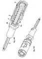
- Fig. 1shows a fixed-dose pen, the dose to be dispensed being adjustable on the dose button 1.
- the penhas a threaded rod 5, which as in the sections of the Figures 3 to 6 shown in cross-section as a star has four points 5b, whereby a robust and simple setting of the fixed-dose is possible.
- the threaded rod 5it is possible for the threaded rod 5 to have a star-shaped cross-section (Swiss cross-shaped), but the star can also have more or fewer points 5b than the Swiss cross.
- Fig. 2shows the pen according to Fig. 1 in perspective view in section AA.
- the guide sleeve 3can be connected to the housing 10 and is mounted so that it cannot rotate relative to the housing 10.
- the rotating sleeve 2is mounted rotatably but axially not displaceably by means of a snap bead 2a.
- the dosing button 1is also rotatably but not axially displaceable by means of a snap bead 3a.
- a spring element 4in a preferred embodiment as a spring wire or spring band wound two to three times, so that when the rotating sleeve 2 is rotated relative to the guide sleeve 3 , the spring 4, which is connected, for example, by bends 4a at the opposite ends, once to the guide sleeve 3 and once to the rotating sleeve 2, is tensioned and thus provides a restoring force against the adjusting rotating movement.
- the dosing button 1is preferably not pulled out axially, but only rotated. On the inside of the dosing button 1 there are four webs pointing in the axial direction, which engage in corresponding grooves in the rotating sleeve 2 and thus couple the dosing button 1 to the rotating sleeve 2 in such a way that a rotary movement of the dosing button 1 can be converted into a rotating movement of the rotating sleeve 2 .
- the dosing button 1 and rotating sleeve 2could also be designed in one piece or as one element.
- the rotating sleeve 2has snap elements 2b prestressed radially inward, in the exemplary embodiment of FIG Fig. 5 shown in section CC two opposing snap elements 2b biased radially inward. These snap elements 2b engage in the four grooves 5a of the threaded rod 5 during the pulling-up movement or are rotated past the prongs 5b. During the pulling-up process, the threaded rod 5 is secured against rotation by being held by a snap element 3b of the guide sleeve 3.
- the rotating sleeve 2has a snap element 2c which is pretensioned radially outward and which is inserted into an in Figure 5
- the window shown in section BB or an opening 3c of the guide sleeve 3is rotated when the opening process is finished, and latches in this window 3c so that a turning back of the rotating sleeve 2 relative to and within the guide sleeve 3 due to the force of the pre-tensioned by the adjustment process Spring 4 is not possible.
- the penAfter it has been distributed, the pen can be drawn up again by turning the dose button 1 and the same dose can then be distributed.
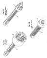
- the threaded rod 5can easily be produced in the injection molding process with two mold halves if the threaded rod 5 forms a simple cross in cross section.
- the grooves 5ain which the radially inwardly pretensioned snapper 2b of the guide sleeve 2 engages, can be designed to be continuous and thus interrupt the thread 5c on the outside of the threaded rod 5.
- high or steep flanks for the snapper 2bcan be achieved.
- the outer or peripheral areas of the threaded rod 5have a slope 5d so that the radially inwardly pretensioned snapper 2b of the rotary sleeve 2 can slide over it more easily when being pulled on. This also results in a higher flank 5e on the side of the axially continuous groove 5a of the threaded rod 5, in which the radially inwardly pretensioned snapper 2b of the rotating sleeve 2 engages, whereby a turning back of the rotating sleeve 2 relative to the threaded rod 5 can be reliably prevented .
- a claw safety deviceis provided on the threaded rod 5.
- Thishas an extension 5f on the proximal side of the threaded rod 5, from which, for example, four webs 5g protrude in the axial direction distally, which, after the last dose has been poured out, move into corresponding counterstops 2g of the rotating sleeve 2 or are pushed into it.
- the threaded rod 5is moved axially into the rotating sleeve 2 so far that the claws or webs 5g of the threaded rod 5 rest against the corresponding counterstops 2g of the rotating sleeve 2.
- the webs of the claw safety devicecan move into the corresponding counterstops 2g, for example by being at least slightly or partially mechanically deformed or compressed when the injection device is actuated and, for example, when the end position is reached, they relax and move into the counterstops, which are designed as recesses, for example.
- the claws of the claw safety devicecan also be resiliently mounted. When the injection device is actuated, the resiliently mounted claws 5g slide, as in FIG Figure 12A shown, along the counter-stop 2g by being deflected in the direction of the arrow. After the dose has been delivered, the claws snap 5g, as in Figure 12B shown, in the counter-stop 2g, so that the injection device can no longer be pulled open.
- the inventive design of the claw safety device 5g and the counter-stops 2gensures that after the last dose has been poured out, the pen can no longer be pulled out, because the threaded rod via the form fit between the claw safety device 5g and Counterstops 2g is held against rotation. Further dosing of the pen is no longer possible because the threaded rod 5 is mounted in the guide sleeve 3 so that it cannot rotate, and the claw coupling 2g, 5g prevents the dosing button 1 or rotating sleeve 2 from rotating.
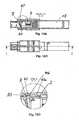
- a two-chamber ampoule 13can be used for insertion or screwing into the injection device.
- the ampoule 13is screwed into the pen, whereby if the ampoule 13 is screwed sufficiently far into the pen, it comes into contact with the guide sleeve 3 and pushes it together with the dosing button 1 in the proximal direction of the pen. As a result, the dosing button 1 is pushed out of the pen, which makes it possible to adjust or open the pen in the first place.
- a locking ring 40 or locking ringcan be provided, the two fork-shaped locking pawls 40a of which protrude into corresponding recesses in the rotating sleeve 2 and prevent rotation of the rotating sleeve 2. Since the injection device is loaded by rotating the rotating sleeve 2, the pulling-up or loading of the injection device is prevented by the engagement of the locking ring 40 in the rotating sleeve 2.
- the ampoule sleevewhich is screwed into the pen to mix the two-chamber ampoule, is screwed in.
- the locking ring 40is moved by the ampoule sleeve from the locking position into an unlocked position in which the locking ring 40 is no longer with the rotating sleeve 2 is locked.
- the two pawls 40 of the locking or locking ring 40as in FIG Figures 13E through 13G shown, in that inclined surfaces 40b or sliding surfaces arranged on the insides of the two fork-shaped pawls 40a slide relative to inclined surfaces 30 or sliding surfaces formed on the guide sleeve 3, so that the locking ring 40 disengages from the rotary sleeve 2 and the rotary sleeve 2 is released for rotary movements, for example for dose or dosage settings.
- an indicator sleeve 6is provided on the threaded rod 5, which is connected to the threaded rod 5 in a fixed manner, that is, non-rotatably and axially shift-proof.
- a viewing window 12can be formed by transparent materials or openings 12.3, 12.9, 12.7 in (from the inside to the outside) guide sleeve 3, ampoule holder 9 and threaded sleeve 7.
- the display sleeve 6When the ampoule 13 is mixed, the display sleeve 6 is pushed into the latter (not previously).
- the display sleeve 6could also be rotatably attached to the rear stopper 13a, so that the display sleeve 6 is initially decoupled from the mechanism of the pen and is provided in the ampoule part.
- the display sleeve 6Since the display sleeve 6 is directly coupled to the threaded rod 5, the display sleeve 6 cannot slip. This means that there is no false indication, even if the pen is subjected to a strong impact, for example by being dropped.
- the guide sleeve 3also serves as a privacy screen, since the window 12.3 in the guide sleeve 3 is displaced relative to the window 12.7 in the threaded sleeve 7 before the ampoule 13 is screwed in. Only after the ampoule 13 has been screwed in and mixed is the window 12.3 of the guide sleeve 3 aligned with the window 12.7 of the threaded sleeve 7, so that the display sleeve 6 mounted on the threaded rod 5 becomes visible and readable.
- the release button 11is positioned through a hole 10a in the housing 10 and has two spring arms 11a in the circumferential direction, which press the release button 11 radially outward away from the guide sleeve 3.
- the spring arms 11adescribe a radius which is smaller than the outer radius of the guide sleeve 3, so that in this way the radially outwardly directed prestressing of the release button 11 can be implemented.
- the display 6is connected to the piston rod or threaded rod 5 in the in Figures 11A and 11B
- the embodiments shownare coupled directly and can be rotated around them without self-locking.
- the display element 6is secured against axial displacement in the pen.
- the piston rod 5has a thread or threaded section on the outside into which the display 6 or, when the display 6 is translated, a transmission element coupled to the display 6, for example a gear or as in FIG Figure 11C shown a gear with internal thread, can engage. If a translation is used, a gap is created between the gearwheel, which is directly coupled to the rack, and the display, through which, for example, the guide sleeve 3 can be passed.
- the remaining quantity indicatorcan also be used.
- the remaining quantity display element 6could for example be mounted on the piston rod 5 so that it cannot rotate, so that the piston rod 5 moves through the remaining volume display 6 during a distribution, which is itself mounted in the pen so that it cannot move axially.
- a self-locking remaining quantity display 6can be implemented by a suitable thread pitch which is material-dependent and in the exemplary embodiment is approximately 45 °.
- the coupling between the remaining quantity display element 6 and the rack 5is preferably designed in such a way that when the rack 5 has been completely passed through the remaining quantity display element has performed a full rotation of 360 °.
- the display element 6can be designed in such a way that it can also be displaced by means of an external thread.
- An axially displaceable remaining quantity indicator 6would also be conceivable, which moves in the axial direction of the pen while the rack 5 is being passed through, for example by thread engagement on the outside of the remaining quantity indicator 6 in an internal thread in the housing of the pen constant preset dose can be used, the remaining amount display showing, for example, 14 maximum possible units to be dispensed, which are counted back to 0 starting from an initial state.
Landscapes
- Health & Medical Sciences (AREA)
- Vascular Medicine (AREA)
- Engineering & Computer Science (AREA)
- Anesthesiology (AREA)
- Biomedical Technology (AREA)
- Heart & Thoracic Surgery (AREA)
- Hematology (AREA)
- Life Sciences & Earth Sciences (AREA)
- Animal Behavior & Ethology (AREA)
- General Health & Medical Sciences (AREA)
- Public Health (AREA)
- Veterinary Medicine (AREA)
- Infusion, Injection, And Reservoir Apparatuses (AREA)
- Lock And Its Accessories (AREA)
- Diaphragms For Electromechanical Transducers (AREA)
- Fuel-Injection Apparatus (AREA)
- Injection Moulding Of Plastics Or The Like (AREA)
Abstract
Description
Translated fromGermanDie vorliegende Erfindung bezieht sich auf eine Gewindestange für eine Injektionsvorrichtung beziehungsweise einen Pen, sowie auf eine Klauensicherung, sowie auf eine Injektionsvorrichtung mit einer solchen Gewindestange und/oder einer Klauensicherung.The present invention relates to a threaded rod for an injection device or a pen, as well as to a claw safety device, and to an injection device with such a threaded rod and / or a claw safety device.
Wird eine in einer Injektionsvorrichtung zum Beispiel in einer Ampulle enthaltene Substanz vollständig oder teilweise abgegeben, wobei eine zur Verdrängung der Substanz zum Beispiel durch Verschieben eines Stopfens innerhalb der Ampulle vorgesehene auf den Stopfen drückende Gewinde- oder Kolbenstange eingeschoben wird, so kann es dazu kommen, dass diese Kolben- oder Gewindestange wieder versehentlich innerhalb der Injektionsvorrichtung zurückgezogen wird, was zu einer Fehlbedienung der Injektionsvorrichtung führen kann.If a substance contained in an injection device, for example in an ampoule, is completely or partially dispensed, with a threaded rod or piston rod being pushed onto the stopper, which is provided for displacing the substance, for example by moving a stopper inside the ampoule, then this can result in: that this piston rod or threaded rod is again accidentally withdrawn within the injection device, which can lead to incorrect operation of the injection device.
Es ist eine Aufgabe der Erfindung eine Gewindestange und eine Injektionsvorrichtung mit einer solchen Gewindestange vorzuschlagen, welche sicherstellen können, dass die Gewindestangen nach dem vollständigen Einschieben nicht mehr herausgezogen werden kann.It is an object of the invention to propose a threaded rod and an injection device with such a threaded rod, which can ensure that the threaded rods can no longer be pulled out after they have been completely pushed in.
Diese Aufgabe wird durch den Gegenstand des Anspruchs 1 gelöst. Vorteilhafte Ausführungsformen ergeben sich aus den abhängigen Ansprüchen.This object is achieved by the subject matter of
Eine erfindungsgemäße Gewindestange weist ein Verdrehsicherungselement, insbesondere eine Klauensicherung auf, welche so an der Gewindestange und bevorzugt an deren proximalen Ende angeordnet ist, dass die Verdrehsicherung oder Klauen in diese Verdrehsicherungselemente oder Klauen haltende oder eingreifende Gegenelemente eingeschoben werden können, wenn die Gewinde- oder Kolbenstange bis zu einer vorgegebenen zum Beispiel distalen Endposition innerhalb der Injektionsvorrichtung verschoben wurde. Dabei sind die Klauen oder Verdrehsicherungsgegenelemente, in welche die Klauen oder Verdrehsicherungselemente der Gewindestange eingreifen, vorzugsweise mit der Injektionsvorrichtung oder einem Teil davon, wie zum Beispiel einem Gehäuse der Injektionsvorrichtung, fest verbunden. Eine in die Injektionsvorrichtung eingeschobene Gewindestange kann somit nach dem Einschieben der Klauen oder Verdrehsicherungselemente in die entsprechenden Verdrehsicherungsgegenelement der Injektionsvorrichtung nicht mehr gedreht werden, da durch den Eingriff der Elemente, wie zum Beispiel den Eingriff von vorstehenden Stegen in Nuten, die Gewinde- oder Kolbenstange mit der Injektionsvorrichtung verdrehsicher gekoppelt wird oder ist, was ein Verdrehen unmöglich macht. Eine Gewindestange kann somit in einer eingeschobenen Endposition gehalten werden, da eine Verdrehung aufgrund der Klauensicherung nicht mehr möglich ist und eine axiale Verschiebung aufgrund der Gewindekopplung verhindert wird.A threaded rod according to the invention has an anti-rotation element, in particular a claw lock, which is arranged on the threaded rod and preferably at its proximal end in such a way that the anti-rotation lock or claws can be inserted into counter-elements holding or engaging these anti-rotation elements or claws when the threaded rod or piston rod was moved up to a predetermined, for example, distal end position within the injection device. The claws or anti-rotation counter elements, in which the claws or anti-rotation elements of the threaded rod engage, are preferably firmly connected to the injection device or a part thereof, such as a housing of the injection device. A threaded rod pushed into the injection device can therefore no longer be rotated after the claws or anti-rotation elements have been inserted into the corresponding counter-anti-rotation element of the injection device, since the engagement of the elements, such as the engagement of protruding webs in grooves, causes the threaded or piston rod to move the injection device is or is coupled in a twist-proof manner, which makes twisting impossible. A threaded rod can thus be held in an inserted end position, since rotation is no longer possible due to the claw lock and an axial displacement is prevented due to the threaded coupling.
Somit ist bei der Verwendung der erfindungsgemäßen Gewindestange keine weitere Haltevorrichtung in der Injektionsvorrichtung zwingend von Nöten, welche die Gewindestange beispielsweise in der Endposition hält und fixiert. Die Fixierung der Gewindestange wird bereits durch die erfindungsgemäße Gewindestange und die daran ausgebildete oder angeordnete Klauensicherung erreicht.Thus, when using the threaded rod according to the invention, no further holding device is absolutely necessary in the injection device, which holds and fixes the threaded rod, for example, in the end position. The fixing of the threaded rod is already achieved by the threaded rod according to the invention and the claw safety device formed or arranged thereon.
Die Verdrehsicherungsgegenelemente der Injektionsvorrichtung können als Einbuchtungen in oder Klauen an der Injektionsvorrichtung oder an Teilen der Injektionsvorrichtung, wie der Drehhülse, ausgebildet sein. Es sind zahlreiche Ausgestaltungen der Gegenelemente der Injektionsvorrichtung möglich, wobei die Verdrehsicherungsgegenelemente bevorzugt so ausgebildet sind, dass sie mit den in die Verdrehsicherungsgegenelemente eingreifenden oder eingeschobenen Verdrehsicherungselementen der Gewindestange einen Formschluss bilden, so dass eine Verdrehung der Gewindestange in proximaler und/oder distaler Richtung durch den Formschluss verhindert wird. Die Verdrehsicherungselemente an der Gewindestange können zum Beispiel federnd gelagert sein, um bei beispielsweise in der distalen Endposition in die Verdrehsicherungsgegenelemente der Injektionsvorrichtung einschnappen oder einrasten zu können. Auch können die Verdrehsicherungselemente der Gewindestange fest gelagert sein und zumindest leicht oder teilweise verformbar sein, so dass sie in der distalen Endposition in die Verdrehsichenmgsgegenelemente der Injektionsvorrichtung einschnappen oder einrasten können. Sind die Verdrehsieherungselemente in die Verdrehsicherungsgegenelemente eingeschnappt oder eingefahren, sind sie formschlüssig mit den Verdrehsicherungsgegenelementen verbunden, so dass eine Bewegung oder Drehung der Gewindestange in proximaler und/oder distaler Richtung verhindert werden kann.The anti-rotation counter-elements of the injection device can be designed as indentations in or claws on the injection device or on parts of the injection device, such as the rotating sleeve. Numerous configurations of the counter-elements of the injection device are possible, the anti-rotation counter-elements preferably being designed in such a way that they form a form fit with the anti-rotation elements of the threaded rod that engage or slide into the anti-rotation counter-elements, so that the threaded rod can be rotated in the proximal and / or distal direction by the Form fit is prevented. The anti-rotation elements on the threaded rod can be resiliently mounted, for example, in order to be able to snap into the counter-anti-rotation elements of the injection device when, for example, in the distal end position. The anti-rotation elements of the threaded rod can also be fixedly mounted and at least slightly or partially deformable so that they can snap or engage in the counter-anti-rotation elements of the injection device in the distal end position. If the anti-rotation elements are snapped or retracted into the anti-rotation counter-elements, they are positively connected to the anti-rotation counter-elements, so that a movement or rotation of the threaded rod in the proximal and / or distal direction can be prevented.
Um die Menge einer abzugebenden Substanz an einer Injektionsvorrichtung einzustellen, wird an einem Einstellelement, meistens einem Dosierknopf oder einem Dosierring, eine Einstellbewegung zum Beispiel durch Drehung des Dosierelementes durchgeführt, wobei die Größe der Drehung, also zum Beispiel ein Drehwinkel, definiert, welche Menge der Substanz mit dem nächsten Injektionsvorgang aus der Injektionsvorrichtung abgegeben wird. Bei einer Injektionsvorrichtung, welche eine feste und zum Beispiel voreingestellte Menge einer Substanz abgeben soll, einem so genannten fixed-dose-Pen, wird die Einstellbewegung durchgeführt, um zum Beispiel den Pen zur Abgabe einer vordefinierter Dosis aufzuziehen.In order to set the amount of a substance to be dispensed on an injection device, an adjusting movement is carried out on an adjusting element, usually a dosing button or a dosing ring, for example by rotating the dosing element, the size of the rotation, for example an angle of rotation, defining the amount of the Substance is released from the injection device with the next injection process. In the case of an injection device which is intended to deliver a fixed and, for example, preset amount of a substance, a so-called fixed-dose pen, the setting movement is carried out in order, for example, to draw up the pen to deliver a predefined dose.
Die Gewindestange der Injektionsvorricbtung ist so ausgebildet, dass diese im Zusammenwirken mit einem oder mehreren zum Beispiel an dem Pen oder dem Gehäuse des Pens angeordneten oder auch an mit dem Einstellelement gekoppelten Eingriffelementen, zum Beispiel elastischen oder radial nach innen oder außen vorgespannten Schnappelementen oder Rastelementen, vorgegebene festgelegte Drehpositionen einnehmen kann, in welchen diese Rastelemente in Eingriffbereiche der Gewindestange eingreifen und so für eine Kopplung zwischen der Gewindestange und dem Pen oder zwischen der Gewindestange und einem Einstellelement sorgen. Hierzu weist die Gewindestange bevorzugt in Längsrichtung der Gewindestange Eingriflbereiche, Nuten oder Rillen auf, welche zum Beispiel auch das Gewinde auf der Außenseite der Gewindestange durchbrechen können, so dass die Gewindestange im Querschnitt zum Beispiel als Stern mit drei, bevorzugt vier oder auch mehr als vier, wie zum Beispiel fünf oder sechs, Zacken oder Stegen ausgebildet ist, so dass eine robuste und einfache Einstellung einer fest vorgegebenen Dosis (fixed-dose) dadurch ermöglicht wird, dass die Gewindestange zum Beispiel bei einer kreuzförmigen Ausgestaltung mit vier Zacken nur zu vier definierten und stabilen Drehpositionen gedreht werden kann. Bei den stabilen Drehpositionen greifen ein oder mehrere Eingriffselemente, welche der konkreten Ausformung der Gewindestange entsprechend zum Beispiel um diese herum angeordnet sind, in die Nuten der Gewindestange ein und halten diese bei sternförmiger Ausbildung zum Beispiel nur in vier definierten Drehpositionen. Eine Drehung der Gewindestange führt somit zum Beispiel nur nach 90°, 180°, 270° und weiteren Vielfachen von 90° zu Stabilen und definierten Drehpositionen der Gewindestange.The threaded rod of the injection device is designed in such a way that it interacts with one or more, for example, arranged on the pen or the housing of the pen or also on engagement elements coupled to the setting element, for example elastic or radially inwardly or outwardly biased snap elements or latching elements, can assume predetermined fixed rotational positions in which this Latching elements engage in engagement areas of the threaded rod and thus ensure a coupling between the threaded rod and the pen or between the threaded rod and an adjusting element. For this purpose, the threaded rod preferably has engagement areas, grooves or grooves in the longitudinal direction of the threaded rod, which, for example, can also break through the thread on the outside of the threaded rod, so that the threaded rod in cross section, for example, as a star with three, preferably four or even more than four , such as five or six, prongs or webs is formed, so that a robust and simple setting of a fixed dose (fixed dose) is made possible by the fact that the threaded rod only defines four in the case of a cross-shaped design with four prongs, for example and stable rotating positions. In the stable rotational positions, one or more engagement elements, which are arranged around this according to the specific shape of the threaded rod, for example, engage in the grooves of the threaded rod and, in the case of a star-shaped design, only hold them in four defined rotational positions, for example. A rotation of the threaded rod thus leads, for example, only after 90 °, 180 °, 270 ° and further multiples of 90 ° to stable and defined rotational positions of the threaded rod.
Vorzugsweise ist die Gewindestange so ausgebildet, dass zumindest im Bereich der Nuten oder axial verlaufenden Eingriffsbereiche die äußeren oder peripheren Bereiche der Gewindestange eine leichte Abschrägung aufweisen, so dass die bevorzugt radial in Richtung auf die Gewindestange vorgespannten Eingriffselemente, welche vorteilhaft eine Drehung der Gewindestange in eine Richtung durch ein Gleiten über die abgeschrägten Bereiche ermöglichen und eine Drehung in die Sperr- oder Gegenrichtung durch Eingriff in die Eingriffsbereiche sperren, bei einer Drehung der Gewindestange entgegen der Spernichtung leicht außer Eingriff gebracht und aus den Eingriffsbereichen herausgedrückt oder herausgegeben werden können, um durch die Drehbewegung über die abgeschrägten Außenbereiche in den benachbarten Eingriffsbereich geführt zu werden. Eine Abschrägung der Außenbereiche führt dazu, dass ein Zacken oder Steg der Gewindestange zwischen zwei Nuten oder Eingriffsbereichen eine höhere und eine niedrige Flanke hat, wobei die höhere Flanke bevorzugt auf derjenigen Seite angeordnet ist, aus welcher das Eingriffselement nicht mehr herausgedrückt werden soll, um über den abgeschrägten Außenbereich zu gelangen, so dass eine Blockierung der Drehung der Gewindestange durch das Eingriffselement realisiert werden kann. Andererseits wird durch die kleinere Flanke ein Weiterdrehen der Gewindestange vereinfacht, da das Eingriffselement nur den Weg der kleineren Flanke entlang zu dem abgeschrägtern Bereich heraus gedrückt werden muss, um die Drehung der Gewindestange zu ermöglichen. Vorzugsweise sind die Eingriffselemente auch mit einer Schräge versehen, welche beispielsweise korrespondierend zur Schräge des peripheren Bereichs der Gewindestange ausgebildet sein kann und welche ein Herausdrücken des Eingriffselements bei einer Drehbewegung in einer Freigaberichtung vereinfacht oder ermöglicht.The threaded rod is preferably designed in such a way that at least in the area of the grooves or axially extending engagement areas the outer or peripheral areas of the threaded rod have a slight bevel, so that the engagement elements, which are preferably radially pretensioned in the direction of the threaded rod, which advantageously allow a rotation of the threaded rod in a Allow direction by sliding over the beveled areas and block a rotation in the locking or opposite direction by engaging in the engagement areas, can be easily disengaged when the threaded rod is rotated against the locking direction and pushed out of the engagement areas or released to through the Rotary movement to be guided over the beveled outer areas in the adjacent engagement area. A bevel of the outer areas means that a prong or web of the threaded rod between two grooves or engagement areas has a higher and a lower flank, the higher flank preferably being arranged on the side from which the engagement element should no longer be pushed out to over to reach the beveled outer area, so that a blocking of the rotation of the threaded rod can be realized by the engagement element. On the other hand, further turning of the threaded rod is simplified by the smaller flank, since the engagement element only has to be pressed out along the path of the smaller flank to the beveled area in order to enable the threaded rod to rotate. The engagement elements are preferably also provided with a bevel, which can for example be designed to correspond to the bevel of the peripheral region of the threaded rod and which simplifies or enables the engagement element to be pushed out during a rotary movement in a release direction.
Bevorzugt weist die Gewindestange am proximalen Ende eine Erweiterung auf, wie zum Beispiel einen umlaufenden Ring oder radial abstehenden Steg, von welchem in distale Richtung gerichtet mindestens ein Eingriffselement, wie zum Beispiel ein oder mehrere Stege vorstehend herausragen, um zum Beispiel bei einem Eingriff mit entsprechenden Gegenelementen zum Beispiel nach vollständigem Einschieben der Gewindestange eine Klauensicherung zu realisieren, wobei die Gewindestange so in korrespondierende Gegenelemente oder Klauen eingreift, dass eine weitere Drehbewegung der Gewindestange oder des Dosierelements relativ zur Injektionsvorrichtung blockiert wird und die Injektionsvorrichtung somit nicht mehr verwendet werden kann.The threaded rod preferably has an extension at the proximal end, such as a circumferential ring or radially protruding web, from which at least one engagement element, such as one or more webs, protrudes in the distal direction, for example to enable corresponding Counter-elements, for example, to implement a claw lock after the threaded rod has been fully inserted, the threaded rod engaging in corresponding counter-elements or claws in such a way that further rotary movement of the threaded rod or the dosing element relative to the injection device is blocked and the injection device can no longer be used.
Die Erfindung bezieht sich gemäß einer weiteren Ausführungsform auf eine Injektionsvorrichtung mit einer wie oben beschriebenen Gewindestange.According to a further embodiment, the invention relates to an injection device with a threaded rod as described above.
Vorteilhaft ist an der Injektionsvorrichtung ein Dosierelement, wie zum Beispiel ein Dosierknopf oder ein Drehknopf vorgesehen, welcher mit weiteren Elementen, wie zum Beispiel einer Drehhülse oder einem Drehelement verbunden sein kann. Mittels des Dosierelementes kann die abzugebende Dosis eingestellt, also die Injektionsvorrichtung aufgezogen oder aufdosiert werden. Vorzugsweise wird durch eine Drehbewegung des Dosierelementes ein Federelement, wie zum Beispiel eine Torsionsfeder, gespannt, welche die Energie für die nachfolgende Injektion und den Vorschub der Gewindestange speichert und nach Betätigung eines Auslöseelementes frei gibt. Eine mit dem Dosierelement verbundene Drehhülse oder auch das Dosierelement selber weist bevorzugt mindestens ein und vorteilhaft mindestens zwei zum Beispiel einander gegenüber liegende radial nach innen vorgespannte Eingriffselemente auf, welche in korrespondierende Eingriffsbereiche der Gewindestange eingreifen können und eine Drehung der Gewindestange relativ zur Drehhülse oder zum Dosierelement in eine Richtung ermöglichen. Bei einer Drehung der Drehhülse oder des Dosierelementes in eine Gegenrichtung bleiben die Eingriffselemente im Eingriff mit der Gewindestange und nehmen diese mit, so dass zum Beispiel die in der Torsionsfeder durch die Einstellbewegung gespeicherte Energie in eine Drehbewegung der Gewindestange umgesetzt werden kann.A dosing element, such as a dosing button or a rotary knob, is advantageously provided on the injection device, which can be connected to further elements, such as a rotary sleeve or a rotary element. The dose to be dispensed can be set by means of the dosing element, that is to say the injection device can be drawn up or dosed up. A spring element, such as a torsion spring, is preferably tensioned by a rotary movement of the dosing element, which spring element stores the energy for the subsequent injection and the advancement of the threaded rod and releases it after actuation of a trigger element. A rotating sleeve connected to the dosing element or the dosing element itself preferably has at least one and advantageously at least two, for example, radially inwardly pretensioned engagement elements lying opposite one another, which can engage in corresponding engagement areas of the threaded rod and a rotation of the threaded rod relative to the rotating sleeve or the dosing element enable in one direction. When the rotating sleeve or the dosing element is rotated in an opposite direction, the engagement elements remain in engagement with the threaded rod and take it with them, so that, for example, the energy stored in the torsion spring by the adjustment movement can be converted into a rotational movement of the threaded rod.
Vorzugsweise ist an der Drehhülse oder dem Dosierelement auch noch mindestens ein radial nach außen vorgespanntes Eingriffselement vorgesehen, welches zum Beispiel in ein Fenster oder eine Nut oder Ausnehmung der Injektionsvorrichtung eingreifen kann, um so die Drehhülse oder das Dosierelement in einer vorgegebenen Drehposition zum Beispiel nach dem Einstellen der Dosis oder Aufziehen der Injektionsvorrichtung zu halten oder zu arretieren. Das zur Arretierung dienende Halteelement kann zum Beispiel mittels eines Auslöseknopfes wieder freigegeben werden, wobei zum Beispiel nach Betätigung des Auslöseknopfes das radial nach außen vorgespannte Eingriffselement wieder in eine radial nach innen gerichtete Richtung geschoben wird, so dass die Drehhülse oder das Dosierelement nicht mehr mit der Injektionsvorrichtung gekoppelt ist und eine Drehbewegung zum Beispiel durch die Torsionsfeder ermöglicht wird.Preferably, at least one engagement element which is biased radially outward is also provided on the rotating sleeve or the dosing element, which engagement element can, for example, engage in a window or a groove or recess of the injection device so that the rotating sleeve or the dosing element is in a predetermined rotating position, for example after the Adjusting the dose or withdrawing the injection device to hold or lock it in place. The retaining element used for locking can be released again, for example, by means of a release button, for example after actuation of the release button the radially outwardly prestressed engagement element is pushed again in a radially inward direction so that the rotary sleeve or the dosing element no longer is coupled to the injection device and a rotary movement is made possible, for example by the torsion spring.
Vorzugsweise weist die Injektionsvorrichtung als Teil der Injektionsvorrichtung integriert und zum Beispiel fest mit der Injektionsvorrichtung verbunden oder als separates Element vorgesehen mindestens ein Führungselement auf, welches ebenfalls mindestens ein elastisches und zum Beispiel radial nach innen vorgespanntes Halteelement aufweist, welches in mindestens einen Eingriffsbereich der Gewindestange eingreifen kann, um zum Beispiel eine Drehbewegung der Gewindestange relativ zur Injektionsvorrichtung in eine Richtung zu ermöglichen und in die Gegenrechtung zu sperren. Bevorzugt weist das Führungselement auch ein Innengewinde auf, welches auch aus einem oder mehreren Teilgewindesegmenten bestehen kann. Dieses Innengewinde oder die Teilgewindesegmente können so ausgebildet sein, dass diese mehrere Anlageflanken haben, wie beispielsweise bei dem in
Bevorzugt weist die Injektionsvorrichtung Eingriffselemente oder Klauen auf, um mit entsprechenden Eingriffselementen oder Klauen der Gewindestange eine Klauenkupplung zu realisieren. Die Eingriffselemente der Injektionsvorrichtung können zum Beispiel an einer in proximale Richtung weisenden Oberfläche einer Drehhülse, einer Führungshülse oder der Injektionsvorrichtung selbst vorgesehen sein.The injection device preferably has engagement elements or claws in order to implement a claw coupling with corresponding engagement elements or claws of the threaded rod. The engagement elements of the injection device can be provided, for example, on a surface of a rotating sleeve, a guide sleeve or the injection device itself that faces in the proximal direction.
Die Injektionsvorrichtung kann ein Übertragungselement aufweisen welches mit einem Ausschüttelement, wie zum Beispiel einer Kolbenstange oder einer Gewindestange, der Injektionsvorrichtung gekoppelt ist und welches mit einem Anzeigeelement, welches zum Beispiel mit einer Ampulle, welche in die Injektionsvorrichtung eingesetzt werden kann, gekoppelt werden kann.The injection device can have a transmission element which is coupled to a dispensing element, such as a piston rod or a threaded rod, of the injection device and which can be coupled to a display element, for example with an ampoule that can be inserted into the injection device.
Bei der Verwendung von Injektionsvorrichtungen ist es vorteilhaft, wenn eine Anzeige vorgesehen ist, an welcher Daten bezüglich der bereits verabreichten Dosen oder der noch in der Injektionsvorrichtung enthaltenen Dosen oder bezüglich des aktuellen Ausschüttvorganges abgelesen werden können. Jedoch können Probleme auftreten, wenn diese Anzeige aufgrund eines Fehlers nicht richtig funktioniert, da ein Benutzer zum Beispiel fälschlicherweise annimmt, dass noch eine größere als tatsächlich vorhandene Substanzmenge in der Injektionsvorrichtung enthalten ist.When using injection devices, it is advantageous if a display is provided on which data relating to the doses already administered or the doses still contained in the injection device or relating to the current dispensing process can be read. However, problems can arise if this display does not work correctly due to an error, for example because a user incorrectly assumes that the injection device still contains a larger amount of substance than is actually present.
Ein Anzeigelement zum Anzeigen eines Verabretchungsparameters, wie zum Beispiel einer in einer Injektionsvorrichtung noch enthaltenen oder bereits aus der Injektionsvorrichtung, wie zum Beispiel aus einer in der Injektionsvorrichtung eingesetzten Ampulle, ausgeschütteten Menge einer Substanz ist möglichst unmittelbar und bevorzugt unmittelbar mit einem Ausschüttelement der Injektionsvorrichtung, also zum Beispiel einer Kolbenstange oder Gewindestange, welche zum Beispiel für einen Vorschub zum Beispiel eines Stopfens in eine Ampulle oder in einem Reservoir sorgen, gekoppelt Durch die möglichst unmittelbare Kopplung des Anzeigelementes mit dem Vorschubelement können Fehler bei der Anzeige weitgehend ausgeschlossen werden, da keine oder nur wenige Fehler verursachende oder fehleranfällige Zwischenelemente vorgesehen sind. Somit kann eine robuste und zuverlässige unmittelbare Anzeige geschaffen werden, welche beispielsweise als Restmengenanzeige oder Echtzeitanzeige verwendet werden kann. Das Anzeigeelement kann als Verabreichungsparameter auch die Uhrzeit der Abgabe oder die Ausschüttzeit beispielsweise zusätzlich anzeigen, um einem Benutzer zu ermöglichen, den Abgabezeitpunkt überprüfen zu können oder um den Abgabezeitpunkt zum Beispiel speichern und für Auswertungszwecke verwenden zu können.A display element for displaying a Verabretchungsparameter, such as an amount of a substance still contained in an injection device or already dispensed from the injection device, such as from an ampoule inserted in the injection device, is as close as possible and preferably directly to a dispensing element of the injection device, that is For example, a piston rod or threaded rod, which, for example, provide for a feed, for example, a stopper into an ampoule or in a reservoir, coupled.By coupling the display element with the feed element as directly as possible, errors in the display can be largely ruled out, since none or only Few errors causing or error-prone intermediate elements are provided. A robust and reliable immediate display can thus be created, which can be used, for example, as a remaining quantity display or real-time display. The display element can also display the time of delivery or the delivery time as an administration parameter, for example, in order to enable a user to check the delivery time or to be able to store the delivery time, for example, and use it for evaluation purposes.
Vorzugsweise ist das Anzeigelement unmittelbar mit dem Ausschüttelement verbunden, also zum Beispiel relativ zu diesem verschiebe- und verdrehsichere gelagert, und weist zum Beispiel an einer Außenseite in Umfangrichtung und/oder Längsrichtung eine Markierung zur Dosisanzeige auf, welche beispielsweise an einem Fenster oder mittels einer Markierung, an welcher sich das Anzeigelement durch Drehen und Verschieben vorbei bewegt, abgelesen werden kann.Preferably, the display element is directly connected to the dispensing element, so for example mounted relative to this so that it cannot be displaced and twisted, and has, for example, on an outer side in the circumferential direction and / or longitudinal direction a marking for the dose display, which is for example on a window or by means of a marking which the display element moves past by rotating and shifting can be read.
Alternativ ist das Anzeigelement mit dem Vorschub- oder Ausschüttelement gekoppelt, also nicht unmittelbar mit diesem verbunden, wobei die Kopplung beispielsweise durch einen Gewindeeingriff oder einen anderen Bewegung oder eine Kraft übertragenden Mechanismus, wie zum Beispiel eine Schnecke, ein Zahnrad oder ein Getriebe, realisiert sein kann. Beispielsweise kann das Anzeigeelement ein Gewinde und bei der Ausbildung eines Anzeigeelementes als Hülse ein Innengewinde aufweisen, welches in ein Außengewinde einer Kolbenstange oder Gewindestange eingreift, so dass das zum Beispiel axial verschiebesicher aber drehbar in der Injektionsvorrichtung gelagerte Anzeigeelement unmittelbar durch eine Drehung oder Verschiebung der Gewindestange oder Kolbenstange gedreht wird, wobei an Hand der Drehung zum Beispiel durch Beschriftung auf der Außenseite des Anzeigelementes an einer Skalierung, welche sich beispielsweise nicht mitdreht, abgelesen werden kann, welche Dosis abgegeben wurde oder noch vorhanden ist. Dabei ist im Falle eines Gewindeeingriffes das Gewinde vorteilhaft selbsthemmungsfrei ausgebildet, so dass ein einfaches Drehen des Anzeigeelementes ermöglicht wird und das Anzeigeelement zu keiner Behinderung zum Beispiel einer Aufdosier- oder Ausschüttbewegung führt.Alternatively, the display element is coupled to the feed or dispensing element, i.e. not directly connected to it, the coupling being implemented, for example, by thread engagement or another movement or a force-transmitting mechanism such as a worm, a gear or a gear can. For example, the display element can have a thread and, if a display element is designed as a sleeve, an internal thread which engages in an external thread of a piston rod or threaded rod, so that the display element, for example axially secure but rotatably mounted in the injection device, can be directly rotated or displaced or piston rod is rotated, with the help of the rotation, for example, by labeling on the outside of the display element on a scale that does not rotate, for example, which dose has been delivered or is still present. In the case of thread engagement, the thread is advantageously designed to be non-self-locking, so that simple rotation of the display element is made possible and the display element does not interfere with, for example, a dispensing or dispensing movement.
Vorteilhaft kann das Anzeigeelement nicht an einer Injektionsvorrichtung, sondern an einer in die Injektionsvorrichtung emzusetzenden Ampulle vorgesehen sein, welche erst bei oder nach dem Einsetzen in die Injektionsvorrichtung so mit zum Beispiel einem Koppelelement der Injektionsvorrichtung gekoppelt wird, dass eine Bewegung zum Beispiel eines Stopfens der Ampulle in eine entsprechende Bewegung des Anzeigeelementes umgesetzt wird, wodurch eine Echtzeitanzeige realisiert werden kann.Advantageously, the display element can not be provided on an injection device, but on an ampoule to be placed in the injection device, which is only coupled to, for example, a coupling element of the injection device during or after insertion into the injection device, so that a movement of, for example, a stopper of the ampoule is converted into a corresponding movement of the display element, whereby a real-time display can be realized.
Die Injektionsvoniehtung weist vorteilhaft mindestens eine Durchbrechung, wie zum Beispiel ein Sichtfenster, auf, an welchem zum Beispiel eine auf der Außenseite des Anzeigelementes angebrachte Markierung des in der Injektionsvorrichtung vorgesehenen Anzeigeelementes abgelesen werden kann.The injection device advantageously has at least one opening, such as a viewing window, from which, for example, a marking of the display element provided in the injection device, which is attached to the outside of the display element, can be read.
Zur axial verschiebesicheren aber drehbaren Lagerung des Anzeigeelement kann zum Beispiel eine Ringnut oder ein Ringsteg an der Injektionsvorrichtung vorgesehen sein, in welche ein entsprechendes Gegenelement, also zum Beispiel ein Ringsteg oder eine Ringnut der Anzeigeelementes, eingreift.For axially displaceable but rotatable mounting of the display element, for example, an annular groove or an annular web can be provided on the injection device, in which a corresponding counter-element, for example an annular web or an annular groove of the display element, engages.
Die Injektionsvorrichtung kann so ausgebildet sein, dass das Anzeigeelement innerhalb der Injektionsvorrichtung, zum Beispiel bei dem Einsetzen einer Ampulle, verschiebbar ist, wobei zum Beispiel die Anzeige des Anzeigeelementes nicht an einem Fenster ablesbar ist, wenn keine Ampulle eingesetzt ist und beispielsweise ein Farbcode an der Umfangsseite des Anzeigeelementes anzeigt, dass eine Ampulle fehlt. Erst bei oder nach Einsetzen der Ampulle wird zum Beispiel durch den Ampullen-Einsetzvorgang das Anzeigeelement so relativ zu einer Ableseposition, wie zum Beispiel einem Sichtfenster, verschoben, dass die Anzeige oder eine Beschriftung des Anzeigeelementes erkennbar wird. Dabei kann sich das Anzeigeelement auch vollständig oder zum Teil innerhalb der Ampulle befinden.The injection device can be designed so that the display element can be displaced within the injection device, for example when an ampoule is inserted, with the display of the display element not being readable on a window if no ampoule is inserted and, for example, a color code on the Circumferential side of the display element indicates that an ampoule is missing. Only when or after the ampoule has been inserted is the display element shifted relative to a reading position, such as a viewing window, for example by the ampoule insertion process, so that the display or a label on the display element can be seen. The display element can also be located completely or partially within the ampoule.
Die Injektionsvorrichtung kann ein Verfahren zum Sichern einer Mechanik umfassen, insbesondere zum Sichern einer Einstellmechanik oder eines Einstellelements einer Injektionsvorrichtung eine Betätigung, wie zum Beispiel eine Sicherung vor Verdrehung des Einstellelements, wobei die Betätigungs- oder Verdrehsicherung durch ein Einschieben einer Ampulle in die Injektionsvorrichtung aufgehoben werden kann.The injection device can comprise a method for securing a mechanism, in particular for securing an adjusting mechanism or an adjusting element of an injection device, an actuation, such as, for example, securing against rotation of the adjusting element, the actuation or rotation safeguarding being canceled by inserting an ampoule into the injection device can.
Wenn eine Injektionsvorrichtung verwendet wird, in welche eine Ampulle vor dem Gebrauch der Injektionsvorrichtung eingesetzt wird, wie zum Beispiel eine unmittelbar vor dem Gebrauch einzusetzende und abzumischende 2-Kammer-Ampulle, kann es zu Problemen kommen, wenn ein Benutzer der Injektionsvorrichtung schon vor dem Einsetzen der Ampulle einen Einstell- oder Bedienvorgang durchführt.If an injection device is used in which an ampoule is inserted before the injection device is used, for example a 2-chamber ampoule which is to be inserted and mixed immediately before use, problems can arise if a user of the injection device is already used before insertion the ampoule carries out a setting or operating process.
Eine Injektionsvorrichtung weist ein Gehäuse und ein in dem Gehäuse gelagertes oder mit dem Gehäuse verbundenes oder gekoppeltes Bedienelement auf, wobei das Bedienelement, wie zum Beispiel ein Einstell-, Druck- oder Drehknopf, so in dem Gehäuse gelagert oder mit dem Gehäuse gekoppelt oder verbunden ist, dass das Bedienelement von einer ersten Halteverbindung in einer ersten Position im Bezug auf das Gehäuse der Injektionsvorrichtung gehalten, also zum Beispiel gegen eine axiale Verschiebung gesichert, werden kann. Dabei ist die Halteverbindung so ausgebildet, dass diese während und bevorzugt nach dem Einbringen oder Einsetzen oder Einschieben einer Ampulle gelöst wird, so dass das Bedienelement nach dem Einbringen der Ampulle in eine zweite bevorzugt axial in proximale Richtung zur ersten Halteposition versetzte Halteposition verschoben wird und dort von einer zweiten Halteverbindung gehalten wird. Dabei wird vorzugsweise das Bedienelement durch das Einbringen oder Einschieben der Ampulle ebenfalls relativ zum Gehäuse der Injektionsvorrichtung verschoben, also zum Beispiel in proximale Richtung aus der Injektionsvorrichtung herausgeschoben. Jedoch kann die Injektionsvorrichtung auch so aufgebaut sein, dass eine Kupplung oder ein Koppelelement vorgesehen ist, welches durch das Einschieben der Ampulle verschoben wird, indem es zum Beispiel in Anlage mit einem proximalen Ampullenrand kommt, und so das Bedienelement freigibt. Dabei kann das Bedienelement selbst relativ zur Injektionsvorrichtung still stehen oder ebenfalls mit verschoben werden.An injection device has a housing and an operating element mounted in the housing or connected or coupled to the housing, the operating element, such as an adjustment, push button or rotary knob, being mounted in the housing or being coupled or connected to the housing that the operating element can be held by a first holding connection in a first position in relation to the housing of the injection device, that is to say secured against axial displacement, for example. The holding connection is designed so that it is released during and preferably after the introduction or insertion or insertion of an ampoule, so that after the introduction of the ampoule, the operating element is moved into a second holding position, preferably axially offset in the proximal direction to the first holding position, and there is held by a second holding connection. In this case, the operating element is preferably also displaced relative to the housing of the injection device by the introduction or pushing in of the ampoule, that is to say, for example, pushed out of the injection device in the proximal direction. However, the injection device can also be constructed in such a way that a coupling or a coupling element is provided which is displaced when the ampoule is pushed in, for example by coming into contact with a proximal ampoule edge, thus releasing the operating element. The operating element itself can stand still relative to the injection device or can also be moved with it.
Vorzugsweise ist das Bedienelement oder Koppelelement so in der Injektionsvorrichtung gelagert, dass erst nach dem vollständigen Einsetzen oder Einschieben oder Eindrehen einer Ampulle, was mit dem Abmischen von zum Beispiel zwei in der Ampulle enthaltenen Substanzen einhergehen kann, aus der ersten Halteverbindung in die zweite Halteverbindung verschoben wird. Beispielsweise kann das Bedien- oder Koppelelement so in der Injektionsvorrichtung vorgesehen sein, dass eine einzubringende oder einzuschiebende Ampulle mit einem zum Beispiel vorher bekannten Maß oder Abmessungen erst auf den letzten Teil der Einschubstrecke mit dem Koppel- oder Bedienelement in Berührung kommt, so dass die Ampulle vor dieser letzten Wegstrecke in die Injektionsvorrichtung zum Beispiel eingeschraubt werden kann, ohne das Koppel- oder Bedienelement zu berühren bzw. zu verschieben und erst die nachfolgende Berührung der Ampulle mit dem Koppel- oder Bedienelement und die Verschiebung durch das dann vollständige Einschieben der Ampulle dazu führt, dass das Koppelelement die Mechanik zur Bedienung der Injektionsvorrichtung entriegelt oder dass das Bedienelement zum Beispiel durch Ausfahren aus dem Gehäuse der Injektionsvorrichtung für die Bedienung und zum Beispiel Einstellung durch einen Benutzer freigegeben wird.The control element or coupling element is preferably stored in the injection device in such a way that it is only moved out of the first holding connection into the second holding connection after an ampoule has been completely inserted or pushed in or screwed in, which may be associated with mixing, for example, two substances contained in the ampoule becomes. For example, the operating or coupling element can be provided in the injection device in such a way that an ampoule to be introduced or pushed in, for example with a previously known dimension or dimensions, only comes into contact with the coupling or operating element on the last part of the insertion path, so that the ampoule can be screwed into the injection device before this last distance, for example, without touching or moving the coupling or operating element and only the subsequent contact of the ampoule with the coupling or operating element and the displacement through the then complete insertion of the ampoule leads to this that the coupling element unlocks the mechanism for operating the injection device or that the operating element is released for operation and, for example, adjustment by a user, for example by extending it out of the housing of the injection device.
Die erste und/oder zweite Halteverbindung können zum Beispiel durch eine Rastverbindung realisiert werden, wobei beispielsweise ein Rastring vorgesehen sein kann, welcher von einem Koppel- oder Bedienelement radial nach ihnen oder nach außen ragt und zusammen mit einer Ringnut der Injektionsvorrichtung oder des Gehäuses eine erste Halteverbindung bildet und einer weiteren Ringnut der Injektionsvorrichtung oder des Gehäuses die zweite Rastverbindung bildet. Ebenso kann das Halteelement auch durch andere mechanische Koppelungen realisiert werden, welche bevorzugt lösbar sind, wenn eine bestimmte Mindestkraft auf diese Kopplung einwirkt.The first and / or second retaining connection can be implemented, for example, by a latching connection, whereby, for example, a latching ring can be provided which protrudes radially towards them or outwards from a coupling or operating element and, together with an annular groove of the injection device or the housing, a first Forms retaining connection and a further annular groove of the injection device or the housing forms the second latching connection. Likewise, the holding element can also be implemented by other mechanical couplings, which are preferably releasable when a certain minimum force acts on this coupling.
Die Mechaniksicherung kann zum Beispiel dadurch realisiert werden, dass eine Verdrehsicherung des Einstellelements zum Beispiel durch Führung von vorstehenden Nuten des Einstellelementes vorgesehen ist, so dass das Einstellelement in einer distalen Position gegen eine Verdrehung gesichert ist. Nach dem Eindrehen einer Ampulle wird das verdrehgesicherte Einstellelement so weit in proximale Richtung geschoben, dass die zur Verdrehsicherung dienenden Nuten aus dem diese Nuten haltenden und führenden Elementen zum Beispiel der Injektionsvorrichtung oder des Gehäuses herausgeschoben werden und somit eine Drehung und damit Betätigung des Einstellelementes möglich ist. Ebenso kann auch ein Koppelelement vorgesehen sein, welches eine Drehbewegung des Einstellelementes erst nach einer Verschiebung in proximale Richtung freigibt. Beispielsweise kann dieses Koppelelement ringförmig aufgebaut sein und nach innen und außen weisende Stege haben, welche in Nuten des Einstellelements und Nuten der Injektionsvorrichtung bzw. des Gehäuses eingreifen und so eine Verdrehung des Einstellelementes gegen das Gehäuse der Injektionsvorrichtung verhindern. Wird das Einstellelement durch eine in die Injektionsvorrichtung eingebrachte und zum Beispiel eingedrehte Ampulle zum Beispiel gegen die Kraft einer das Koppelelement in distale Richtung vorspannende Feder verschoben, bis die Stege des Koppelelementes aus den Nuten des Einstellelements und/oder aus den Nuten der Injektionsvorrichtung herausgeschoben werden, so wird die Kopplung der Einstellvorrichtung mit der Injektionsvorrichtung gelöst und die Injektionsvorrichtung kann nach dem bevorzugt vollständigen Einschieben der Ampulle in die Injektionsvorrichtung betätigt werden.The mechanical lock can be implemented, for example, in that the setting element is secured against rotation, for example by guiding protruding grooves of the setting element, so that the setting element is secured against rotation in a distal position. After screwing in an ampoule, the anti-twist setting element is pushed so far in the proximal direction that the grooves used to prevent rotation are pushed out of the elements holding and guiding these grooves, for example the injection device or the housing, so that the setting element can be rotated and thus operated . Likewise, a coupling element can also be provided which releases a rotary movement of the setting element only after it has been displaced in the proximal direction. For example, this coupling element can be annular and have inward and outward facing webs which engage in grooves of the setting element and grooves of the injection device or the housing and thus prevent the setting element from rotating against the housing of the injection device. If the setting element is displaced by an ampoule which has been introduced into the injection device and is screwed in, for example, against the force of a spring which prestresses the coupling element in the distal direction, until the webs of the coupling element are pushed out of the grooves of the setting element and / or out of the grooves of the injection device, in this way the coupling of the setting device to the injection device is released and the injection device can be actuated after the ampoule has preferably been completely inserted into the injection device.
Wenn Injektionsgeräte und insbesondere Injektionsvorrichtungen zur dosierten Abgabe einer Substanz hergestellt werden, so ist deren Aufbau und insbesondere die Dosiermechanik auf einen vorgegebenen Anwendungsfall kanfiguriert. Zum Beispiel wird zur Abgabe einer großen Substanzmenge oder zur Bereitstellung eines großen Hubes des Einstellelementes eine große Steigung eines Innengewindes der Injektionsvorrichtung vorgesehen, in welchem eine Gewindestange oder ein Einstellelement geführt werden. Soll eine einmal entwickelte Injektionsvorrichtung auch für die Abgabe einer zum Beispiel niedriger zu dosierenden Substanz verwendet werden, so muss diese neu konzipiert und hergestellt werden, um zum Beispiel ein Innengewinde mit kleinerer Steigung vorzusehen.If injection devices and, in particular, injection devices for the dosed delivery of a substance are manufactured, their structure and in particular the dosing mechanism are configured for a given application. For example, in order to dispense a large amount of substance or to provide a large stroke of the adjusting element, a large pitch of an internal thread of the injection device is provided, in which a threaded rod or an adjusting element is guided. If an injection device, once developed, is also to be used for the delivery of a substance to be dosed lower, for example, it must be redesigned and manufactured in order to provide an internal thread with a smaller pitch, for example.
Eine Injektionsvorrichtung weist ein Innengewinde zur Führung zum Beispiel einer Gewindestange oder eines Einstellelementes auf, wobei das Innengewinde so ausgebildet ist, dass es mehrere Anlageflanken aufweist, um verschiedene Gewindestangen mit einem Außengewinde unterschiedlicher Steigung führen zu können, ohne dass das Innengewinde der Injektionsvorrichtung ausgewechselt oder verändert werden muss. Dabei ist das Innengewinde vorzugsweise aus einzelnen Gewindeabschnitten aufgebaut. Diese Gewindeabschnitte können in Umfangsrichtung zueinander versetzt sein und sich zum Beispiel über 1/N-tel des Umfanges erstrecken, wobei N eine natürliche Zahl ist. Beispielsweise sind die Gewindeabschnitte so ausgebildet, dass sie sich über eine halben, einen drittel oder einen viertel Umfang an der Innenseite der Injektionsvorrichtung oder eines Gehäuses davon erstrecken. Die einzelnen Gewindeabschnitte weisen dabei erfindungsgemäß mindestens zwei Anlageflanken auf, an welchen Gewinde unterschiedlicher Steigung geführt werden können.An injection device has an internal thread for guiding, for example, a threaded rod or an adjusting element, the internal thread being designed in such a way that it has several contact flanks in order to be able to guide different threaded rods with an external thread of different pitch without the internal thread of the injection device being exchanged or changed must become. The internal thread is preferably made up of individual thread sections. These thread sections can be offset from one another in the circumferential direction and, for example, extend over 1 / Nth of the circumference, where N is a natural number. For example, the threaded sections are designed such that they extend over a half, a third or a quarter of the circumference on the inside of the injection device or a housing thereof. According to the invention, the individual thread sections have at least two contact flanks on which threads of different pitches can be guided.
Vorzugsweise besitzen die Gewindeabschnitte mindestens vier Seitenflächen, in welchen ein Gewinde geführt werden kann, wobei jeweils zwei Seitenflächen zueinander parallel sind. Dabei wechseln sich in Umfangsrichtung, das heißt bei einem Umlauf um ein Gewindesegment oder Gewindeteilelement, die Anlageflächen zur Führung der verschiedenen Gewinde mittelbar oder unmittelbar ab, das heißt die Anlageflächen können entweder unmittelbar aneinander stoßen oder durch Gewindeabschnittssegmente oder Gewindeabschnittsteilstücke, welche zum Beispiel zur Führung weiterer Gewinde unterschiedlicher Steigung dienen, verwendet werden.The threaded sections preferably have at least four side surfaces in which a thread can be guided, with two side surfaces being parallel to one another. The contact surfaces for guiding the various threads alternate directly or indirectly in the circumferential direction, i.e. when rotating around a thread segment or thread sub-element, i.e. the contact surfaces can either directly abut one another or through thread segment segments or thread segment segments which, for example, are used to guide further threads Threads of different pitch are used.
Es ist möglich, dass ein solches Gewinde oder Gewindeteilstück so aufgebaut ist, dass mehr als zwei Gewinde unterschiedlicher Steigung geführt werden können. Hierzu kann das Gewinde oder die Gewindesegmenteanlageflächen zur Führung von zum Beispiel Gewindestangen mit einer variablen Steigung zwischen einer durch die Gewindesegmente vorgegebenen minimalen Steigung und einer maximalen Steigung haben. Es ist auch möglich, dass die Gewindesegmente mehr Anlageflächen besitzen und in Umfangsrichtung so angeordnet sind, dass zum Beispiel nur Gewinde mit definierten Steigungen, wie zum Beispiel drei verschiedenen vorgegebenen Steigungen geführt werden können.It is possible for such a thread or thread section to be constructed in such a way that more than two threads with different pitches can be guided. For this purpose, the thread or the thread segment contact surfaces for guiding threaded rods, for example, can have a variable pitch between a minimum pitch predetermined by the thread segments and a maximum pitch. It is also possible that the thread segments have more contact surfaces and are arranged in the circumferential direction in such a way that, for example, only threads with defined pitches, such as three different predetermined pitches, can be guided.
Allgemein kann in Abhängigkeit von der Ausbildung eines Gewindesegmentes, insbesondere der Ausbildung der Anlageflächen des Gewindesegments, und in Abhängigkeit von der Verteilung der Gewindesegmente in Umfangsrichtung vorgegeben werden, welche Außengewinde durch solche ein oder mehrere Innengewinde unterschiedlicher Steigung realisierende Gewindesegmente geführt werden können.In general, depending on the design of a thread segment, in particular the design of the contact surfaces of the thread segment, and depending on the distribution of the thread segments in the circumferential direction, it is possible to specify which external threads can be guided by thread segments realizing one or more internal threads of different pitch.
Somit können in einer einzigen Injektionsvorrichtung bzw. in einem einzigen ausgebildeten Innengewinde Elemente mit einem Außengewinde unterschiedlicher Steigung geführt werden, ohne dass das Innengewinde oder die Injektionsvorrichtung konstruktiv verändert werden muss. Somit kann die gleiche Injektionsvorrichtung für unterschiedliche Anwendungen verwendet werden, bei welchen zur Dosierung zum Beispiel kleine oder auch große Hübe auszuführen sind.Thus, elements with an external thread of different pitch can be guided in a single injection device or in a single internal thread without the internal thread or the injection device having to be structurally changed. The same injection device can thus be used for different applications in which, for example, small or large strokes have to be carried out for dosing.
Die Erfindung wird nachfolgend anhand von Ausführungsbeispielen beschrieben. Es zeigen:
Figur 1- eine Ausführungsform einer Injektionsvorrichtung in Draufsicht;
Figur 2- eine perspektivische Querschnittsansicht der Injektionsvorrichtung entlang des Schnittes A-A in
Figur 1 Figur 3- eine Schnittbildansicht bei einer alternativen Ausführungsform entlang des Schnittes
A-A von Figur 1 zusammen mit weiteren Schnitten B-B und C-C der Schnittbildansicht; - Figur 4
- die
Injektionsvorrichtung der Figur 3 nach dem Abmischen des Pens und herausgeschobener Mechanik; Figur 5- die Injektionsvorrichtung gemäß
Figur 4 nach Einstellen der Dosis und Spannen der Feder; - Figur 6
- die
Injektionsvorrichtung gemäß Figur 5 nach Ausschütten der Dosis bei blockierter Mechanik und entspannter Feder; Figur 7- eine Querschnittsansicht einer Injektionsvorrichtung ohne eingesetzte Ampulle;
Figur 8- das Detail A in
Figur 7 Figur 9- das abgewickelte Gewinde der Führungshülse gemäß
Figur 8 mit unterschiedlichen Anlageflanken zur Führung verschiedener Gewindestangen mit einem Außengewinde unterschiedlicher Steigung; - Figur 10A
- die Dosiermechanik der Injektionsvorrichtung in perspektivischer Ansicht;
- Figur 10B
- die in
Figur 10A gezeigte Dosiermechanik mit einer Querschnittsansicht des proximalen Teiles; - Figuren 11A- 11C
- verschiedene Ausführungsformen einer Echtzeit- oder Restemengenanzeige;
- Figuren 12A - 12B
- eine Ausführungsform einer erfindungsgemäßen Klauensicherung; und
- Figuren 13A- 13G
- eine Ausführungsform einer erfindungsgemäßen Mechanikverriegelung
- Figure 1
- an embodiment of an injection device in plan view;
- Figure 2
- a perspective cross-sectional view of the injection device along the section AA in FIG
Figure 1 ; - Figure 3
- a sectional view in an alternative embodiment along the section AA of
Figure 1 together with further sections BB and CC of the sectional view; - Figure 4
- the injection device of the
Figure 3 after mixing the pen and pushing out the mechanism; - Figure 5
- the injection device according to
Figure 4 after setting the dose and tensioning the spring; - Figure 6
- the injection device according to
Figure 5 after pouring out the dose with the mechanism locked and the spring relaxed; - Figure 7
- a cross-sectional view of an injection device without an inserted ampoule;
- Figure 8
- the detail A in
Figure 7 to illustrate the thread engagement of the guide sleeve in the threaded rod; - Figure 9
- the developed thread of the guide sleeve according to
Figure 8 with different contact flanks for guiding different threaded rods with an external thread of different pitch; - Figure 10A
- the dosing mechanism of the injection device in a perspective view;
- Figure 10B
- in the
Figure 10A Dosing mechanism shown with a cross-sectional view of the proximal part; - Figures 11A-11C
- various embodiments of a real-time or remaining quantity display;
- Figures 12A-12B
- an embodiment of a claw safety device according to the invention; and
- Figures 13A-13G
- an embodiment of a mechanical lock according to the invention
Der Pen weist eine Gewindestange 5 auf, welche wie in den Schnitten der
Es ist prinzipiell möglich, dass die Gewindestange 5 im Querschnitt sternförmig (Schweizer Kreuz-förmig) ausgebildet sein kann, jedoch kann der Stern auch mehr oder weniger Zacken 5b als das Schweizer Kreuz aufweisen.In principle, it is possible for the threaded
Die Führungshülse 3 kann mit dem Gehäuse 10 verbunden sein und ist relativ zu dem Gehäuse 10 verdrehsicher gelagert. Innerhalb der Führungshülse 3 ist die Drehhülse 2 mittels einer Schnappwulst 2a drehbar, aber axial nicht verschiebbar, gelagert. Auf der Außenseite der Führungshülse 3 ist der Dosierknopf 1 ebenfalls mittels einer Schnappwulst 3a drehbar, aber nicht axial verschiebbar, gelagert. An der proximalen Seite der Drehhülse 2 und verbunden mit der Führungshülse 3 und der Drehhülse 2 befindet sich ein Federelement 4, in einer bevorzugten Ausführungsform als zwei- bis dreimal gewickelter Federdraht oder Federband, so dass, wenn die Drehhülse 2 relativ zur Führungshülse 3 gedreht wird, die Feder 4, welche zum Beispiel durch Aufbiegungen 4a an den entgegengesetzten Enden einmal mit der Führungshülse 3 und einmal mit der Drehhülse 2 verbunden ist, gespannt wird und so für eine Rückstellkraft gegen die EinstellDrehbewegung sorgt.The
Der Dosierknopf 1 wird bevorzugt axial nicht herausgezogen, sondern nur gedreht. Auf der Innenseite des Dosierknopfes 1 befinden sich in axiale Richtung weisend vier Stege, welche in entsprechende Nuten der Drehhülse 2 eingreifen und somit den Dosierknopf 1 mit der Drehhülse 2 so koppeln, dass eine Drehbewegung des Dosierknopfes 1 in eine Drehbewegung der Drehhülse 2 übertragen werden kann. Prinzipiell könnten Dosierknopf 1 und Drehhülse 2 auch einstückig oder als ein Element ausgebildet sein.The
Die Drehhülse 2 weist radial nach innen vorgespannte Schnappelemente 2b, im Ausführungsbeispiel der
Auf der distalen Seite der Drehhülse 2 sind in Umfangsrichtung gegenüberliegend zwei in axialer Richtung vorstehende Anschläge, Stege oder Nocken 2a, 2b vorgesehen, welche eine maximale Drehung der Drehhülse 2 von ca. 110° ermöglichen, da diese Nocken dann in Anlage mit ebenfalls in radialer Richtung, allerdings in proximale Richtung gerichtete, Nocken 3c der Führungshülse 3 kommen.On the distal side of the
Beim Zurückdrehen in der im Schnitt C-C der
Nach erfolgter Ausschüttung kann der Pen durch Drehung des Dosierknopfes 1 wieder neu aufgezogen werden und die gleiche Dosis anschließend ausgeschüttet werden.After it has been distributed, the pen can be drawn up again by turning the
Die Gewindestange 5 kann im Spritzgussverfahren mit zwei Formhälften einfach hergestellt werden, wenn die Gewindestange 5 im Querschnitt ein einfaches Kreuz bildet. In axialer Richtung der Gewindestange 5 können die Nuten 5a, in welche der radial nach innen vorgespannte Schnapper 2b der Führungshülse 2 eingreift, durchgängig ausgebildet sein und unterbrechen so das Gewinde 5c auf der Außenseite der Gewindestange 5. Somit können hohe oder steile Flanken für den Schnapper 2b erzielt werden.The threaded
Die äußeren oder peripheren Bereiche der Gewindestange 5 weisen eine Schräge 5d auf, so dass der radial nach innen vorgespannte Schnapper 2b der Drehhülse 2 leichter beim Aufziehen darüber hinweg gleiten kann. Hierdurch ergibt sich auch eine höhere Flanke 5e auf der Seite der in axialer Richtung durchlaufenden Nut 5a der Gewindestange 5, in welcher der radial nach innen vorgespannte Schnapper 2b der Drehhülse 2 eingreift, wodurch ein Zurückdrehen der Drehhülse 2 relativ zur Gewindestange 5 sicher verhindert werden kann.The outer or peripheral areas of the threaded
Prinzipiell ist es bei einer solchen Ausgestaltung der Gewindestange 5 relativ einfach möglich, die Gewindesteigung im Fertigungsprozess zu verändern, so dass bei gleicher Einstelldrehbewegung von zum Beispiel 110° unterschiedliche abzugebende Dosismengen in Abhängigkeit von der jeweils konkret vorliegenden Gewindesteigung realisiert werden können. Hierbei kann entweder das Innengewinde 3d der Führungshülse 3 korrespondierend zur geänderten Steigung des Außengewindes 5c der Gewindestange 5 geändert werden. Alternativ ist es auch möglich, dass das Innengewinde 3d der Führungshülse 3 so ausgebildet ist, dass verschiedene Steigungen des zu führenden Außengewindes 5c der Gewindestange 5 geführt werden können, und zwar vollständig in einem Bereich von einer minimalen durch das Innengewinde 3d vorgegebenen Steigung bis zu einer maximalen durch das Innengewinde 3d vorgegebenen Steigung.
Um sicherzustellen, dass nach dem Ausschütten der letzten Dosis der Pen nicht mehr aufgezogen werden kann, ist an der Gewindestange 5 eine Klauensicherung vorgesehen. Diese weist an der proximalen Seite der Gewindestange 5 eine Erweiterung 5f auf, von welcher in axialer Richtung nach distal weisend zum Beispiel vier Stege 5g vorstehen, welche nach dem Ausschütten der letzten Dosis in entsprechende Gegenanschläge 2g der Drehhülse 2 einfahren oder in diese eingeschoben werden. Die Gewindestange 5 wird dabei axial so weit in die Drehhülse 2 hineinbewegt, dass die Klauen oder Stege 5g der Gewindestange 5 an den entsprechenden Gegenanschlägen 2g der Drehhülse 2 anliegen. Die Stege der Klauensicherung können in die entsprechenden Gegenanschläge 2g einfahren, indem sie beispielsweise bei einer Betätigung der Injektionsvorrichtung zumindest leicht oder teilweise mechanisch verformt oder komprimiert werden und sich zum Beispiel bei Erreichen der Endposition entspannen und in die beispielsweise als Ausnehmungen ausgebildeten Gegenanschläge einfahren. Die Klauen der Klauensicherung können auch federnd gelagert sein. Wird die Injektionsvorrichtung betätigt, gleiten die federnd gelagerten Klauen 5g, wie in
Zum Einsetzen oder Eindrehen in die Injektionsvorrichtung kann eine Zweikammer-Ampulle 13 verwendet werden. Zum Abmischen wird die Ampulle 13 in den Pen hineingeschraubt, wodurch bei ausreichend weitem Hineinschrauben der Ampulle 13 in den Pen diese in Anlage an die Führungshülse 3 kommt und diese zusammen mit dem Dosierknopf 1 in proximale Richtung des Pens schiebt. Hierdurch wird der Dosierknopf 1 aus dem Pen herausgeschoben, was eine Einstellung oder ein Aufziehen des Pens überhaupt erst ermöglicht.A two-
Beispielsweise kann, wie in den
Zum Entsperren des Rastrings 40 und der Drehhülse 2 wird die Ampullenhülse, welche zum Abmischen der Zwei-Kammer-Ampulle in den Pen eingeschraubt wird, eingedreht. Auf den letzten Millimetern, wie den letzten 1 bis 3 mm, beispielsweise den letzen ca. 2 Millimetern, des Einschraubvorganges, wird der Rastring 40 durch die Ampullenhülse von der Sperrposition in eine entsperrte Position gebracht, in welcher der Rastring 40 nicht mehr mit der Drehhülse 2 verrastet ist. Ist die Ampulle 13 ausreichend weit eingedreht, werden die beiden Sperrklinken 40 des Rast- oder Sperrrings 40, wie in den
Zusätzlich ist auf der Gewindestange 5 noch eine Anzeigenhülse 6 vorgesehen, die fest, d.h. drehfest und axial verschiebesicher, mit der Gewindestange 5 verbunden ist. Auf der Außenseite der Anzeigenhülse 6 sind in umlaufender Richtung die noch auszuschüttenden Dosismengen aufgezeichnet Ein Sichtfenster 12 kann gebildet werden durch transparente Materialien oder Durchbrüche 12.3, 12.9, 12.7 in (von innen nach außen) Führungshülse 3, Ampullenhalter 9 und Gewindehülse 7.In addition, an indicator sleeve 6 is provided on the threaded
Die Anzeigenhülse 6 ist bei abgemischter Ampulle 13 in diese eingeschoben (vorher nicht). Prinzipiell könnte die Anzeigenhülse 6 auch drehbar an dem hinteren Stopfen 13a angebracht sein, so dass die Anzeigenhülse 6 von der Mechanik des Pens zunächst entkoppelt ist und im Ampullenteil vorgesehen ist.When the
Da eine direkte Kopplung der Anzeigenhülse 6 mit der Gewindestange 5 besteht, kann die Anzeigenhülse 6 nicht verrutschen. Hierdurch kann es auch nicht zu einer Fehlanzeige kommen, selbst wenn der Pen zum Beispiel durch ein Herunterfallen einem starken Stoß ausgesetzt wird.Since the display sleeve 6 is directly coupled to the threaded
Die Führungshülse 3 dient auch als Sichtschutz, da das Fenster 12.3 in der Führungshülse 3 relativ zum Fenster 12.7 in der Gewindehülse 7 verschoben ist, bevor die Ampulle 13 eingeschraubt ist. Erst nach dem Einschrauben und Abmischen der Ampulle 13 wird das Fenster 12.3 der Führungshülse 3 in Deckung mit dem Fenster 12.7 der Gewindehülse 7 gebracht, so dass hierdurch die auf der Gewindestange 5 gelagerte Anzeigenhülse 6 sichtbar und ablesbar wird.The
Der Auslöseknopf 11 wird durch ein Loch 10a in dem Gehäuse 10 positioniert und weist in Umlaufrichtung zwei Federarme 11a auf, welche den Auslöseknopf 11 radial nach außen weg von der Führungshülse 3 drücken. Die Federarme 11a beschreiben einen Radius, welcher kleiner als der Außenradius der Führungshülse 3 ist, so dass hierdurch die radial nach außen gerichtete Vorspannung des Auslöseknopfes 11 realisiert werden kann.The
Die Anzeige 6 ist mit der Kolbenstange oder Gewindestange 5 in den in
Die Kolbenstange 5 hat auf der Außenseite ein Gewinde oder Gewindeteilstück, in welches die Anzeige 6, oder bei Übersetzung der Anzeige 6 ein mit der Anzeige 6 gekoppeltes Übertragungselement, zum Beispiel ein Zahnrad oder wie in
Wird anstatt der Zahnstange ein Drehmechanismus unter Verwendung einer Kolbenstange verwendet, so kann auch die Restmengenanzeige eingesetzt werden. Hierzu könnte das Restmengen-Anzeigelement 6 zum Beispiel auf der Kolbenstange 5 verdrehgesichert gelagert sein, so dass sich die Kolbenstange 5 während einer Ausschüttung durch die Restmengenanzeige 6 hindurchbewegt, die selbst axial verschiebegesichert in dem Pen gelagert ist.If a rotating mechanism using a piston rod is used instead of the rack, the remaining quantity indicator can also be used. For this purpose, the remaining quantity display element 6 could for example be mounted on the
Eine selbsthemmungsfreie Restmengenanzeige 6 kann durch eine geeignete Gewindesteigung realisiert werden, die materialabhängig ist und im Ausführungsbeispiel etwa 45° beträgt.A self-locking remaining quantity display 6 can be implemented by a suitable thread pitch which is material-dependent and in the exemplary embodiment is approximately 45 °.
Vorzugsweise ist die Kopplung zwischen Restmengenanzeigeelement 6 und Zahnstange 5 so ausgelegt, dass bei vollständig hindurchgefahrener Zahnstange 5 das Restmengenanzeigeelement eine volle Drehung von 360° ausgeführt hat.The coupling between the remaining quantity display element 6 and the
Bei einer Drehung von > 360° kann das Anzeigeelement 6 so ausgelegt sein, dass dieses mittels Außengewinde zusätzlich verschiebbar ist.With a rotation of> 360 °, the display element 6 can be designed in such a way that it can also be displaced by means of an external thread.
Denkbar wäre auch eine axial verschiebbare Restmengenanzeige 6, welche sich während des Hindurchfahrens der Zahnstange 5 in axiale Richtung des Pens bewegt, zum Beispiel durch einen Gewindeeingriff an der Außenseite der Restmengenanzeige 6 in ein Innengewinde im Gehäuse des Pens. Es kann zum Beispiel ein Pen mit konstanter voreingestellter Dosis verwendet werden, wobei die Restmengenanzeige zum Beispiel 14 maximal mögliche auszuschüttenden Einheiten anzeigt, die ausgehend von einem Anfangszustand auf 0 zurückgezählt werden.An axially displaceable remaining quantity indicator 6 would also be conceivable, which moves in the axial direction of the pen while the
Claims (7)
- An injection device comprising a housing (10), a guide sleeve (3) which is connected to the housing (10) and mounted non-rotatably relative to the housing (10), and a threaded rod (5) which is rotatable and axially displaceable by virtue of a thread coupling, wherein the thread coupling is between the guide sleeve (3) and the threaded rod (5),
wherein the threaded rod (5) includes a rotation-preventing or claw securing means (5g) which engages into openings, recesses, notches, grooves or claws (2g) of the injection device when the threaded rod (5) has been displaced into a distal end position within the injection device to prevent rotation of the threaded rod (5) and thereby axial displacement of the threaded rod (5) relative to the injection device. - An injection device according to claim 1 wherein the rotation-preventing or claw securing means (5g) is disposed at the proximal end of the threaded rod (5).
- An injection device according to one of the preceding claims wherein the rotation-preventing or claw securing means (5g) is disposed at an enlargement (5f) of the threaded rod (5).
- An injection device according to one of the preceding claims wherein the rotation-preventing or claw securing means (5g) has at least one and in particular four rotation-preventing elements or claws.
- An injection device according to the preceding claim wherein the rotation-preventing elements are in the form of limbs on the threaded rod (5).
- An injection device according to one of the two preceding claims wherein the rotation-preventing elements or claws are at least easily and/or partially deformable.
- An injection device according to one of the three preceding claims wherein the rotation-preventing elements or claws are resiliently mounted.
Priority Applications (1)
| Application Number | Priority Date | Filing Date | Title |
|---|---|---|---|
| PL07785091TPL2054112T5 (en) | 2006-08-14 | 2007-08-14 | Injection device with claw-type securing means |
Applications Claiming Priority (2)
| Application Number | Priority Date | Filing Date | Title |
|---|---|---|---|
| DE102006038101ADE102006038101A1 (en) | 2006-08-14 | 2006-08-14 | Injection device with jaw safety |
| PCT/CH2007/000396WO2008019517A1 (en) | 2006-08-14 | 2007-08-14 | Injection device with claw-type securing means |
Publications (3)
| Publication Number | Publication Date |
|---|---|
| EP2054112A1 EP2054112A1 (en) | 2009-05-06 |
| EP2054112B1 EP2054112B1 (en) | 2011-03-30 |
| EP2054112B2true EP2054112B2 (en) | 2021-06-16 |
Family
ID=38683512
Family Applications (1)
| Application Number | Title | Priority Date | Filing Date |
|---|---|---|---|
| EP07785091.5AActiveEP2054112B2 (en) | 2006-08-14 | 2007-08-14 | Injection device with claw-type securing means |
Country Status (9)
| Country | Link |
|---|---|
| US (1) | US8246577B2 (en) |
| EP (1) | EP2054112B2 (en) |
| JP (1) | JP5416583B2 (en) |
| CN (1) | CN101553265B (en) |
| AT (1) | ATE503513T1 (en) |
| AU (1) | AU2007283995B2 (en) |
| DE (2) | DE102006038101A1 (en) |
| PL (1) | PL2054112T5 (en) |
| WO (1) | WO2008019517A1 (en) |
Families Citing this family (53)
| Publication number | Priority date | Publication date | Assignee | Title |
|---|---|---|---|---|
| WO2003068290A2 (en) | 2002-02-11 | 2003-08-21 | Antares Pharma, Inc. | Intradermal injector |
| GB0414054D0 (en) | 2004-06-23 | 2004-07-28 | Owen Mumford Ltd | Improvements relating to automatic injection devices |
| HUE042286T2 (en) | 2005-01-24 | 2019-06-28 | Antares Pharma Inc | Needle-filled pre-filled syringe |
| WO2007131025A1 (en) | 2006-05-03 | 2007-11-15 | Antares Pharma, Inc. | Injector with adjustable dosing |
| WO2007131013A1 (en) | 2006-05-03 | 2007-11-15 | Antares Pharma, Inc. | Two-stage reconstituting injector |
| KR101396797B1 (en) | 2006-06-30 | 2014-05-26 | 애브비 바이오테크놀로지 리미티드 | Automatic injection device |
| DE102007054020A1 (en)* | 2007-11-13 | 2009-05-14 | Tecpharma Licensing Ag | Injection device with uncoupling click mechanism |
| EP3636301A1 (en) | 2008-03-10 | 2020-04-15 | Antares Pharma, Inc. | Injector safety device |
| US8376993B2 (en) | 2008-08-05 | 2013-02-19 | Antares Pharma, Inc. | Multiple dosage injector |
| JP5732039B2 (en) | 2009-03-20 | 2015-06-10 | アンタレス・ファーマ・インコーポレーテッド | Hazardous drug injection system |
| WO2010127146A1 (en) | 2009-04-29 | 2010-11-04 | Abbott Biotechnology Ltd | Automatic injection device |
| US8585656B2 (en)* | 2009-06-01 | 2013-11-19 | Sanofi-Aventis Deutschland Gmbh | Dose setting mechanism for priming a drug delivery device |
| KR200454414Y1 (en)* | 2009-10-07 | 2011-07-01 | 주식회사 대웅제약 | Medicine syringe |
| GB0918145D0 (en) | 2009-10-16 | 2009-12-02 | Owen Mumford Ltd | Injector apparatus |
| WO2011053225A1 (en)* | 2009-10-26 | 2011-05-05 | Shl Group Ab | Medicament delivery device |
| GB0921295D0 (en)* | 2009-12-04 | 2010-01-20 | Owen Mumford Ltd | Injection appaeratus |
| US9572937B2 (en)* | 2010-02-18 | 2017-02-21 | Sanofi-Aventis Deutschland Gmbh | Autoinjector having piston rod with non-circular axial bore slidably arranged on housing shaft to prevent relative rotation |
| BR112012029642B1 (en) | 2010-05-20 | 2020-05-26 | Becton, Dickinson And Company | DRUG ADMINISTRATION DEVICE |
| CA2806983A1 (en)* | 2010-08-06 | 2012-02-09 | Sanofi-Aventis Deutschland Gmbh | Assembly for a drug delivery device, piston rod and drug delivery device |
| EP2438949A1 (en)* | 2010-10-06 | 2012-04-11 | Sanofi-Aventis Deutschland GmbH | Drive mechanism for a drug delivery device and drug delivery device |
| EP2438951A1 (en)* | 2010-10-06 | 2012-04-11 | Sanofi-Aventis Deutschland GmbH | Drive mechanism for a drug delivery device and drug delivery device |
| AR083299A1 (en)* | 2010-10-06 | 2013-02-13 | Sanofi Aventis Deutschland | IMPULSE MECHANISM FOR A DRUG ADMINISTRATION DEVICE AND PHARMACOS ADMINISTRATION DEVICE |
| BR112013018905B1 (en) | 2011-01-24 | 2021-07-13 | Abbvie Biotechnology Ltd | AUTOMATIC INJECTION DEVICES THAT HAVE OVERMOLDED HANDLE SURFACES. |
| JP5833230B2 (en) | 2011-05-19 | 2015-12-16 | ベクトン・ディキンソン・アンド・カンパニーBecton, Dickinson And Company | Injection device with automatic material combination function |
| US9220660B2 (en) | 2011-07-15 | 2015-12-29 | Antares Pharma, Inc. | Liquid-transfer adapter beveled spike |
| US8496619B2 (en) | 2011-07-15 | 2013-07-30 | Antares Pharma, Inc. | Injection device with cammed ram assembly |
| US8834449B2 (en) | 2012-01-23 | 2014-09-16 | Ikomed Technologies, Inc. | Mixing syringe |
| US9751056B2 (en) | 2012-01-23 | 2017-09-05 | Merit Medical Systems, Inc. | Mixing syringe |
| US9486583B2 (en) | 2012-03-06 | 2016-11-08 | Antares Pharma, Inc. | Prefilled syringe with breakaway force feature |
| WO2013149978A1 (en)* | 2012-04-05 | 2013-10-10 | Sanofi-Aventis Deutschland Gmbh | Drive mechanism for a drug injection device comprising adhesive to block drive at end of device life to prevent reuse |
| EP4186545A1 (en) | 2012-04-06 | 2023-05-31 | Antares Pharma, Inc. | Needle assisted jet injection administration of testosterone compositions |
| US9364610B2 (en) | 2012-05-07 | 2016-06-14 | Antares Pharma, Inc. | Injection device with cammed ram assembly |
| CN104955506B (en)* | 2013-02-04 | 2018-09-14 | 赛诺菲-安万特德国有限公司 | Component for medicine delivery device |
| FI3659647T3 (en) | 2013-02-11 | 2024-03-28 | Antares Pharma Inc | NEEDLE-ASSISTED SPRAY INJECTOR WITH REDUCED TRIGGER FORCE |
| CA2905031C (en) | 2013-03-11 | 2018-01-23 | Hans PFLAUMER | Dosage injector with pinion system |
| WO2014165136A1 (en) | 2013-03-12 | 2014-10-09 | Antares Pharma, Inc. | Constant volume prefilled syringes and kits thereof |
| US9931469B2 (en) | 2013-08-19 | 2018-04-03 | Dr. Reddy's Laboratories Ltd. | Selectable single dose auto-injector and methods of making and using same |
| EP3038677A1 (en) | 2013-08-28 | 2016-07-06 | Sanofi-Aventis Deutschland GmbH | Assembly for a drug delivery device |
| CA2922441C (en) | 2013-08-29 | 2018-07-17 | Carebay Europe Ltd | Medicament delivery device |
| CH707217A2 (en) | 2014-02-26 | 2014-04-30 | Tecpharma Licensing Ag | Injection device for titrating and distributing a fixed dose of fluid product e.g. teriparatide for osteoporosis therapy dosing sleeve with screw thread that is engaged with screw thread of rotary case |
| WO2015145294A1 (en) | 2014-03-25 | 2015-10-01 | Wockhardt Limited | Fluid delivery pen with final dose stop and improved dose setting features |
| EP3006068B1 (en) | 2014-10-09 | 2020-12-09 | Ypsomed AG | Medication dispensing apparatus with sub dose prevention |
| DE102014222736A1 (en)* | 2014-11-06 | 2016-05-12 | Vetter Pharma-Fertigung GmbH & Co. KG | drug facility |
| JP6731928B2 (en) | 2015-01-28 | 2020-07-29 | ノボ・ノルデイスク・エー/エス | Piston rod drive for injection devices |
| DE202015007351U1 (en)* | 2015-10-22 | 2017-01-27 | Haselmeier Ag | injection device |
| EP3478343B1 (en) | 2016-07-01 | 2021-01-06 | Sanofi | Drug delivery device |
| CN106267475A (en)* | 2016-09-28 | 2017-01-04 | 江苏德尔福医疗器械有限公司 | Disposable adjustable syringe |
| US11426526B2 (en) | 2017-02-13 | 2022-08-30 | Tata Elxsi Limited | Dispensing device |
| WO2019088973A1 (en)* | 2017-10-30 | 2019-05-09 | Hewlett-Packard Development Company, L.P. | Stylus |
| CN111491680B (en) | 2017-12-13 | 2023-08-29 | 里珍纳龙药品有限公司 | Device and method for accurate dose delivery |
| CN112672774B (en)* | 2018-09-13 | 2023-04-04 | 株式会社萨珂拉斯 | Injection system, syringe and gasket |
| EP4603120A2 (en) | 2019-06-05 | 2025-08-20 | Regeneron Pharmaceuticals, Inc. | Devices and methods for precision dose delivery |
| USD989279S1 (en) | 2020-11-24 | 2023-06-13 | Takeda Pharmaceutical Company Limited | Fluid delivery device |
Citations (8)
| Publication number | Priority date | Publication date | Assignee | Title |
|---|---|---|---|---|
| US5308340A (en)† | 1989-06-05 | 1994-05-03 | Eli Lilly And Company | Multiple dose injection pen |
| WO2004006997A1 (en)† | 2002-07-16 | 2004-01-22 | Tecpharma Licensing Ag | Administration device comprising a plunger rod with a return lock |
| US20040186441A1 (en)† | 2001-07-30 | 2004-09-23 | Roney Graf | Connecting casing sections of an administering apparatus for administering, in doses, a product which can be delivered |
| US20050261634A1 (en)† | 2002-09-24 | 2005-11-24 | Anders Karlsson | Injecting device |
| DE102006004563A1 (en)† | 2006-01-17 | 2007-07-19 | Tecpharma Licensing Ag | Injection device for administering medication has a casing, a delivery element moving in relation to the casing and a locking element |
| EP1855742A1 (en)† | 2005-02-22 | 2007-11-21 | Tecpharma Licensing AG | Dosing device for setting fine doses |
| EP1888149A1 (en)† | 2005-05-24 | 2008-02-20 | Tecpharma Licensing AG | Threaded rod and dosing device for an injection device |
| EP1923085A1 (en)† | 2006-11-17 | 2008-05-21 | Sanofi-Aventis Deutschland GmbH | Dosing and drive mechanism for drug delivery device |
Family Cites Families (36)
| Publication number | Priority date | Publication date | Assignee | Title |
|---|---|---|---|---|
| DE635934C (en) | 1935-08-25 | 1936-10-01 | Barber Colman Co | Spline connection |
| US3353718A (en)* | 1966-05-24 | 1967-11-21 | Fischer & Porter Co | Syringe, column or the like |
| WO1987002895A1 (en)* | 1985-11-08 | 1987-05-21 | Disetronic Ag | Injection instrument |
| DE3715258C2 (en)* | 1987-05-08 | 1996-10-31 | Haselmeier Wilhelm Fa | Injection device |
| CH675078A5 (en)* | 1988-01-22 | 1990-08-31 | Nosta Ag | |
| DK166948B1 (en)* | 1988-02-10 | 1993-08-09 | Dcp Af 1988 As | DOSING UNIT FOR DOSING A NUMBER OF MEASURED QUANTITIES OF A FLUID, SUCH AS INSULIN, FROM A GLASS STUBLE |
| DE3811973C1 (en)* | 1988-04-11 | 1989-08-03 | Michael Dipl.-Ing. 4403 Senden De Greive | |
| US5279585A (en) | 1992-02-04 | 1994-01-18 | Becton, Dickinson And Company | Medication delivery pen having improved dose delivery features |
| DE4332307C1 (en)* | 1993-09-23 | 1994-09-29 | Heraeus Kulzer Gmbh | Syringe for the metered dispensing of viscous materials, especially of dental materials |
| SE9303568D0 (en)* | 1993-10-29 | 1993-10-29 | Kabi Pharmacia Ab | Improvements in injection devices |
| US5855568A (en) | 1996-11-22 | 1999-01-05 | Liebel-Flarsheim Company | Angiographic syringe and luer connector |
| DE29703820U1 (en)* | 1997-03-03 | 1998-07-02 | Medico Development Investment Co., Ascona | Injection device |
| JP3968445B2 (en)* | 1997-09-16 | 2007-08-29 | 株式会社アルテ | Prefilled syringe |
| US6221053B1 (en)* | 1998-02-20 | 2001-04-24 | Becton, Dickinson And Company | Multi-featured medication delivery pen |
| DE19821934C1 (en) | 1998-05-15 | 1999-11-11 | Disetronic Licensing Ag | Device for the dosed administration of an injectable product |
| FR2783433B1 (en) | 1998-09-18 | 2001-02-16 | Delab | SYRINGES FOR THE ADMINISTRATION OF PASTY OR SEMI-SOLID FORMULATIONS |
| DE29818721U1 (en)* | 1998-10-21 | 2000-03-02 | Medico Development Investment Co., Ascona | Injection device |
| DE19900827C1 (en)* | 1999-01-12 | 2000-08-17 | Disetronic Licensing Ag | Device for the dosed administration of an injectable product |
| WO2000062839A2 (en) | 1999-04-16 | 2000-10-26 | Becton Dickinson And Company | Pen style injector with automated substance combining feature |
| US6599269B1 (en)* | 1999-12-03 | 2003-07-29 | Becton Dickinson And Company | Single-use syringe |
| GB0007071D0 (en) | 2000-03-24 | 2000-05-17 | Sams Bernard | One-way clutch mechanisms and injector devices |
| ES2365807T3 (en) | 2001-05-16 | 2011-10-11 | ELI LILLY & COMPANY | MEDICATION INJECTOR DEVICE WITH MOTOR ASSEMBLY THAT FACILITATES REARME. |
| DE10129585A1 (en) | 2001-06-20 | 2003-01-09 | Disetronic Licensing Ag | Device for the dosed administration of an injectable product |
| DE10163326A1 (en)* | 2001-07-30 | 2003-02-27 | Disetronic Licensing Ag | Administration device with dosing device |
| DE20209051U1 (en)* | 2001-12-21 | 2003-04-24 | Disetronic Licensing Ag, Burgdorf | Medicament administration device has dosage adjuster mounted on piston rod and end stop mounted at end of its path, locking system preventing adjuster from rotating and pressing against stop |
| JP2005515383A (en) | 2002-01-25 | 2005-05-26 | ノボ・ノルデイスク・エー/エス | Linear actuator and medical dosing device incorporating such a linear actuator |
| DE10229138B4 (en)* | 2002-06-28 | 2008-01-31 | Tecpharma Licensing Ag | Product diverter with piston rod emergency reset |
| DE10232412A1 (en)* | 2002-07-17 | 2004-02-05 | Disetronic Licensing Ag | Administration device with priming function |
| US7699816B2 (en)* | 2002-10-15 | 2010-04-20 | Tecpharma Licensing Ag | Injection device with priming stroke |
| JP4546966B2 (en)* | 2003-10-16 | 2010-09-22 | イーライ リリー アンド カンパニー | Constant dose drug dispensing device |
| DE102004004310A1 (en)* | 2004-01-28 | 2005-08-18 | Tecpharma Licensing Ag | Injection device with lockable dosing member |
| DE102004042581B4 (en)* | 2004-09-02 | 2022-09-15 | Ypsomed Ag | Auto-Pen for dual-chamber ampoule |
| US7740618B2 (en)* | 2004-10-14 | 2010-06-22 | Novo Nordisk A/S | Syringe device |
| DE102004055298A1 (en) | 2004-11-16 | 2006-05-24 | Tecpharma Licensing Ag | Device for mixing injected medicine comprises an ampoule sleeve, a mixing sleeve, an abutment and a guiding unit having a power transmission structure which converts a linear into a rotary movement |
| US20090043264A1 (en)* | 2005-04-24 | 2009-02-12 | Novo Nordisk A/S | Injection Device |
| DE102006004561A1 (en) | 2006-01-17 | 2007-07-26 | Tecpharma Licensing Ag | Injection device with secured knob |
- 2006
- 2006-08-14DEDE102006038101Apatent/DE102006038101A1/ennot_activeWithdrawn
- 2007
- 2007-08-14AUAU2007283995Apatent/AU2007283995B2/enactiveActive
- 2007-08-14DEDE502007006851Tpatent/DE502007006851D1/enactiveActive
- 2007-08-14CNCN2007800382930Apatent/CN101553265B/enactiveActive
- 2007-08-14EPEP07785091.5Apatent/EP2054112B2/enactiveActive
- 2007-08-14JPJP2009524061Apatent/JP5416583B2/enactiveActive
- 2007-08-14ATAT07785091Tpatent/ATE503513T1/enactive
- 2007-08-14PLPL07785091Tpatent/PL2054112T5/enunknown
- 2007-08-14WOPCT/CH2007/000396patent/WO2008019517A1/enactiveApplication Filing
- 2009
- 2009-02-13USUS12/371,298patent/US8246577B2/enactiveActive
Patent Citations (8)
| Publication number | Priority date | Publication date | Assignee | Title |
|---|---|---|---|---|
| US5308340A (en)† | 1989-06-05 | 1994-05-03 | Eli Lilly And Company | Multiple dose injection pen |
| US20040186441A1 (en)† | 2001-07-30 | 2004-09-23 | Roney Graf | Connecting casing sections of an administering apparatus for administering, in doses, a product which can be delivered |
| WO2004006997A1 (en)† | 2002-07-16 | 2004-01-22 | Tecpharma Licensing Ag | Administration device comprising a plunger rod with a return lock |
| US20050261634A1 (en)† | 2002-09-24 | 2005-11-24 | Anders Karlsson | Injecting device |
| EP1855742A1 (en)† | 2005-02-22 | 2007-11-21 | Tecpharma Licensing AG | Dosing device for setting fine doses |
| EP1888149A1 (en)† | 2005-05-24 | 2008-02-20 | Tecpharma Licensing AG | Threaded rod and dosing device for an injection device |
| DE102006004563A1 (en)† | 2006-01-17 | 2007-07-19 | Tecpharma Licensing Ag | Injection device for administering medication has a casing, a delivery element moving in relation to the casing and a locking element |
| EP1923085A1 (en)† | 2006-11-17 | 2008-05-21 | Sanofi-Aventis Deutschland GmbH | Dosing and drive mechanism for drug delivery device |
Also Published As
| Publication number | Publication date |
|---|---|
| WO2008019517A1 (en) | 2008-02-21 |
| PL2054112T5 (en) | 2021-11-08 |
| DE502007006851D1 (en) | 2011-05-12 |
| ATE503513T1 (en) | 2011-04-15 |
| US20090240195A1 (en) | 2009-09-24 |
| CN101553265A (en) | 2009-10-07 |
| AU2007283995A1 (en) | 2008-02-21 |
| EP2054112B1 (en) | 2011-03-30 |
| PL2054112T3 (en) | 2011-09-30 |
| AU2007283995B2 (en) | 2011-11-10 |
| US8246577B2 (en) | 2012-08-21 |
| JP5416583B2 (en) | 2014-02-12 |
| CN101553265B (en) | 2012-04-25 |
| EP2054112A1 (en) | 2009-05-06 |
| JP2010500136A (en) | 2010-01-07 |
| DE102006038101A1 (en) | 2008-02-21 |
Similar Documents
| Publication | Publication Date | Title |
|---|---|---|
| EP2054112B2 (en) | Injection device with claw-type securing means | |
| DE102006038103B4 (en) | Injection device with variable thread guide | |
| DE102006038123C5 (en) | Injection device with mechanical lock | |
| DE102005023854B4 (en) | Dosing device for an injection device | |
| EP1888148B1 (en) | Dosing device for an injection device | |
| WO1995032749A2 (en) | Injection device | |
| EP1890750B1 (en) | Longitudinal compensation for an adjusting device of an injection device | |
| WO2008031238A1 (en) | Injection device with an automatically resettable dose limitation unit | |
| EP2692377B1 (en) | Injection device with dose display element for signalling end of injection | |
| DE102007001432A1 (en) | Blocking unit for dosing mechanism of injection device, has retaining unit acting together with dosing mechanism or dosing unit such that adjusting movement of mechanism or dosing unit in starting position of blocking unit is prevented | |
| WO2007071080A1 (en) | Injection device with axially overlapping dosing or display member | |
| DE20112501U1 (en) | Locking lock for connecting housing parts of an injection or infusion device | |
| WO2008148540A1 (en) | Adjustment and filling fixation after dispensing the last dose | |
| EP2692376B1 (en) | Injection device with helical or spiral dose scale | |
| WO2004006997A1 (en) | Administration device comprising a plunger rod with a return lock | |
| WO2008019513A1 (en) | Injection device comprising a real-time indicator | |
| WO2006072188A1 (en) | Dosing mechanism for an injection device with gearing | |
| WO2003086512A1 (en) | Device for administering an injectable product |
Legal Events
| Date | Code | Title | Description |
|---|---|---|---|
| PUAI | Public reference made under article 153(3) epc to a published international application that has entered the european phase | Free format text:ORIGINAL CODE: 0009012 | |
| 17P | Request for examination filed | Effective date:20090316 | |
| AK | Designated contracting states | Kind code of ref document:A1 Designated state(s):AT BE BG CH CY CZ DE DK EE ES FI FR GB GR HU IE IS IT LI LT LU LV MC MT NL PL PT RO SE SI SK TR | |
| AX | Request for extension of the european patent | Extension state:AL BA HR MK RS | |
| 17Q | First examination report despatched | Effective date:20100111 | |
| GRAP | Despatch of communication of intention to grant a patent | Free format text:ORIGINAL CODE: EPIDOSNIGR1 | |
| GRAS | Grant fee paid | Free format text:ORIGINAL CODE: EPIDOSNIGR3 | |
| GRAA | (expected) grant | Free format text:ORIGINAL CODE: 0009210 | |
| AK | Designated contracting states | Kind code of ref document:B1 Designated state(s):AT BE BG CH CY CZ DE DK EE ES FI FR GB GR HU IE IS IT LI LT LU LV MC MT NL PL PT RO SE SI SK TR | |
| REG | Reference to a national code | Ref country code:GB Ref legal event code:FG4D Free format text:NOT ENGLISH | |
| REG | Reference to a national code | Ref country code:CH Ref legal event code:EP | |
| REG | Reference to a national code | Ref country code:IE Ref legal event code:FG4D | |
| REF | Corresponds to: | Ref document number:502007006851 Country of ref document:DE Date of ref document:20110512 Kind code of ref document:P | |
| REG | Reference to a national code | Ref country code:DE Ref legal event code:R096 Ref document number:502007006851 Country of ref document:DE Effective date:20110512 | |
| REG | Reference to a national code | Ref country code:NL Ref legal event code:VDEP Effective date:20110330 | |
| PG25 | Lapsed in a contracting state [announced via postgrant information from national office to epo] | Ref country code:LV Free format text:LAPSE BECAUSE OF FAILURE TO SUBMIT A TRANSLATION OF THE DESCRIPTION OR TO PAY THE FEE WITHIN THE PRESCRIBED TIME-LIMIT Effective date:20110330 Ref country code:SE Free format text:LAPSE BECAUSE OF FAILURE TO SUBMIT A TRANSLATION OF THE DESCRIPTION OR TO PAY THE FEE WITHIN THE PRESCRIBED TIME-LIMIT Effective date:20110330 Ref country code:LT Free format text:LAPSE BECAUSE OF FAILURE TO SUBMIT A TRANSLATION OF THE DESCRIPTION OR TO PAY THE FEE WITHIN THE PRESCRIBED TIME-LIMIT Effective date:20110330 Ref country code:GR Free format text:LAPSE BECAUSE OF FAILURE TO SUBMIT A TRANSLATION OF THE DESCRIPTION OR TO PAY THE FEE WITHIN THE PRESCRIBED TIME-LIMIT Effective date:20110701 | |
| LTIE | Lt: invalidation of european patent or patent extension | Effective date:20110330 | |
| PG25 | Lapsed in a contracting state [announced via postgrant information from national office to epo] | Ref country code:SI Free format text:LAPSE BECAUSE OF FAILURE TO SUBMIT A TRANSLATION OF THE DESCRIPTION OR TO PAY THE FEE WITHIN THE PRESCRIBED TIME-LIMIT Effective date:20110330 Ref country code:CY Free format text:LAPSE BECAUSE OF FAILURE TO SUBMIT A TRANSLATION OF THE DESCRIPTION OR TO PAY THE FEE WITHIN THE PRESCRIBED TIME-LIMIT Effective date:20110330 Ref country code:FI Free format text:LAPSE BECAUSE OF FAILURE TO SUBMIT A TRANSLATION OF THE DESCRIPTION OR TO PAY THE FEE WITHIN THE PRESCRIBED TIME-LIMIT Effective date:20110330 | |
| REG | Reference to a national code | Ref country code:PL Ref legal event code:T3 | |
| REG | Reference to a national code | Ref country code:IE Ref legal event code:FD4D | |
| PG25 | Lapsed in a contracting state [announced via postgrant information from national office to epo] | Ref country code:PT Free format text:LAPSE BECAUSE OF FAILURE TO SUBMIT A TRANSLATION OF THE DESCRIPTION OR TO PAY THE FEE WITHIN THE PRESCRIBED TIME-LIMIT Effective date:20110801 Ref country code:EE Free format text:LAPSE BECAUSE OF FAILURE TO SUBMIT A TRANSLATION OF THE DESCRIPTION OR TO PAY THE FEE WITHIN THE PRESCRIBED TIME-LIMIT Effective date:20110330 | |
| PG25 | Lapsed in a contracting state [announced via postgrant information from national office to epo] | Ref country code:CZ Free format text:LAPSE BECAUSE OF FAILURE TO SUBMIT A TRANSLATION OF THE DESCRIPTION OR TO PAY THE FEE WITHIN THE PRESCRIBED TIME-LIMIT Effective date:20110330 Ref country code:ES Free format text:LAPSE BECAUSE OF FAILURE TO SUBMIT A TRANSLATION OF THE DESCRIPTION OR TO PAY THE FEE WITHIN THE PRESCRIBED TIME-LIMIT Effective date:20110711 Ref country code:RO Free format text:LAPSE BECAUSE OF FAILURE TO SUBMIT A TRANSLATION OF THE DESCRIPTION OR TO PAY THE FEE WITHIN THE PRESCRIBED TIME-LIMIT Effective date:20110330 Ref country code:IS Free format text:LAPSE BECAUSE OF FAILURE TO SUBMIT A TRANSLATION OF THE DESCRIPTION OR TO PAY THE FEE WITHIN THE PRESCRIBED TIME-LIMIT Effective date:20110730 Ref country code:SK Free format text:LAPSE BECAUSE OF FAILURE TO SUBMIT A TRANSLATION OF THE DESCRIPTION OR TO PAY THE FEE WITHIN THE PRESCRIBED TIME-LIMIT Effective date:20110330 | |
| PG25 | Lapsed in a contracting state [announced via postgrant information from national office to epo] | Ref country code:MT Free format text:LAPSE BECAUSE OF FAILURE TO SUBMIT A TRANSLATION OF THE DESCRIPTION OR TO PAY THE FEE WITHIN THE PRESCRIBED TIME-LIMIT Effective date:20110330 Ref country code:NL Free format text:LAPSE BECAUSE OF FAILURE TO SUBMIT A TRANSLATION OF THE DESCRIPTION OR TO PAY THE FEE WITHIN THE PRESCRIBED TIME-LIMIT Effective date:20110330 | |
| PLBI | Opposition filed | Free format text:ORIGINAL CODE: 0009260 | |
| PG25 | Lapsed in a contracting state [announced via postgrant information from national office to epo] | Ref country code:IE Free format text:LAPSE BECAUSE OF FAILURE TO SUBMIT A TRANSLATION OF THE DESCRIPTION OR TO PAY THE FEE WITHIN THE PRESCRIBED TIME-LIMIT Effective date:20110330 | |
| 26 | Opposition filed | Opponent name:SANOFI-AVENTIS DEUTSCHLAND GMBH Effective date:20111223 | |
| PLAX | Notice of opposition and request to file observation + time limit sent | Free format text:ORIGINAL CODE: EPIDOSNOBS2 | |
| BERE | Be: lapsed | Owner name:TECPHARMA LICENSING A.G. Effective date:20110831 | |
| REG | Reference to a national code | Ref country code:DE Ref legal event code:R026 Ref document number:502007006851 Country of ref document:DE Effective date:20111223 | |
| PG25 | Lapsed in a contracting state [announced via postgrant information from national office to epo] | Ref country code:MC Free format text:LAPSE BECAUSE OF NON-PAYMENT OF DUE FEES Effective date:20110831 | |
| PLBB | Reply of patent proprietor to notice(s) of opposition received | Free format text:ORIGINAL CODE: EPIDOSNOBS3 | |
| PG25 | Lapsed in a contracting state [announced via postgrant information from national office to epo] | Ref country code:BE Free format text:LAPSE BECAUSE OF NON-PAYMENT OF DUE FEES Effective date:20110831 Ref country code:IT Free format text:LAPSE BECAUSE OF FAILURE TO SUBMIT A TRANSLATION OF THE DESCRIPTION OR TO PAY THE FEE WITHIN THE PRESCRIBED TIME-LIMIT Effective date:20110330 | |
| PLAF | Information modified related to communication of a notice of opposition and request to file observations + time limit | Free format text:ORIGINAL CODE: EPIDOSCOBS2 | |
| PLAS | Information related to reply of patent proprietor to notice(s) of opposition deleted | Free format text:ORIGINAL CODE: EPIDOSDOBS3 | |
| PLBB | Reply of patent proprietor to notice(s) of opposition received | Free format text:ORIGINAL CODE: EPIDOSNOBS3 | |
| PG25 | Lapsed in a contracting state [announced via postgrant information from national office to epo] | Ref country code:LU Free format text:LAPSE BECAUSE OF NON-PAYMENT OF DUE FEES Effective date:20110814 | |
| PG25 | Lapsed in a contracting state [announced via postgrant information from national office to epo] | Ref country code:BG Free format text:LAPSE BECAUSE OF FAILURE TO SUBMIT A TRANSLATION OF THE DESCRIPTION OR TO PAY THE FEE WITHIN THE PRESCRIBED TIME-LIMIT Effective date:20110630 | |
| PG25 | Lapsed in a contracting state [announced via postgrant information from national office to epo] | Ref country code:TR Free format text:LAPSE BECAUSE OF FAILURE TO SUBMIT A TRANSLATION OF THE DESCRIPTION OR TO PAY THE FEE WITHIN THE PRESCRIBED TIME-LIMIT Effective date:20110330 | |
| REG | Reference to a national code | Ref country code:AT Ref legal event code:MM01 Ref document number:503513 Country of ref document:AT Kind code of ref document:T Effective date:20120831 | |
| PG25 | Lapsed in a contracting state [announced via postgrant information from national office to epo] | Ref country code:AT Free format text:LAPSE BECAUSE OF NON-PAYMENT OF DUE FEES Effective date:20120831 Ref country code:HU Free format text:LAPSE BECAUSE OF FAILURE TO SUBMIT A TRANSLATION OF THE DESCRIPTION OR TO PAY THE FEE WITHIN THE PRESCRIBED TIME-LIMIT Effective date:20110330 | |
| APBM | Appeal reference recorded | Free format text:ORIGINAL CODE: EPIDOSNREFNO | |
| APBP | Date of receipt of notice of appeal recorded | Free format text:ORIGINAL CODE: EPIDOSNNOA2O | |
| APAH | Appeal reference modified | Free format text:ORIGINAL CODE: EPIDOSCREFNO | |
| APBQ | Date of receipt of statement of grounds of appeal recorded | Free format text:ORIGINAL CODE: EPIDOSNNOA3O | |
| REG | Reference to a national code | Ref country code:FR Ref legal event code:PLFP Year of fee payment:9 | |
| REG | Reference to a national code | Ref country code:FR Ref legal event code:PLFP Year of fee payment:10 | |
| PLAB | Opposition data, opponent's data or that of the opponent's representative modified | Free format text:ORIGINAL CODE: 0009299OPPO | |
| R26 | Opposition filed (corrected) | Opponent name:SANOFI-AVENTIS DEUTSCHLAND GMBH Effective date:20111223 | |
| REG | Reference to a national code | Ref country code:FR Ref legal event code:PLFP Year of fee payment:11 | |
| REG | Reference to a national code | Ref country code:FR Ref legal event code:PLFP Year of fee payment:12 | |
| REG | Reference to a national code | Ref country code:CH Ref legal event code:PUE Owner name:YPSOMED AG, CH Free format text:FORMER OWNER: TECPHARMA LICENSING AG, CH | |
| REG | Reference to a national code | Ref country code:DE Ref legal event code:R082 Ref document number:502007006851 Country of ref document:DE Representative=s name:SSM SANDMAIR PATENTANWAELTE RECHTSANWALT PARTN, DE Ref country code:DE Ref legal event code:R081 Ref document number:502007006851 Country of ref document:DE Owner name:YPSOMED AG, CH Free format text:FORMER OWNER: TECPHARMA LICENSING AG, BURGDORF, CH | |
| APBU | Appeal procedure closed | Free format text:ORIGINAL CODE: EPIDOSNNOA9O | |
| REG | Reference to a national code | Ref country code:GB Ref legal event code:732E Free format text:REGISTERED BETWEEN 20210325 AND 20210331 | |
| PUAH | Patent maintained in amended form | Free format text:ORIGINAL CODE: 0009272 | |
| STAA | Information on the status of an ep patent application or granted ep patent | Free format text:STATUS: PATENT MAINTAINED AS AMENDED | |
| 27A | Patent maintained in amended form | Effective date:20210616 | |
| AK | Designated contracting states | Kind code of ref document:B2 Designated state(s):AT BE BG CH CY CZ DE DK EE ES FI FR GB GR HU IE IS IT LI LT LU LV MC MT NL PL PT RO SE SI SK TR | |
| REG | Reference to a national code | Ref country code:DE Ref legal event code:R102 Ref document number:502007006851 Country of ref document:DE | |
| P01 | Opt-out of the competence of the unified patent court (upc) registered | Effective date:20230524 | |
| PGFP | Annual fee paid to national office [announced via postgrant information from national office to epo] | Ref country code:DE Payment date:20240819 Year of fee payment:18 | |
| PGFP | Annual fee paid to national office [announced via postgrant information from national office to epo] | Ref country code:GB Payment date:20240822 Year of fee payment:18 | |
| PGFP | Annual fee paid to national office [announced via postgrant information from national office to epo] | Ref country code:FR Payment date:20240823 Year of fee payment:18 | |
| PGFP | Annual fee paid to national office [announced via postgrant information from national office to epo] | Ref country code:CH Payment date:20240901 Year of fee payment:18 | |
| PGFP | Annual fee paid to national office [announced via postgrant information from national office to epo] | Ref country code:PL Payment date:20240805 Year of fee payment:18 |