EP2053535B1 - Automated detection of cell colonies and coverslip detection using hough transforms - Google Patents
Automated detection of cell colonies and coverslip detection using hough transformsDownload PDFInfo
- Publication number
- EP2053535B1 EP2053535B1EP08253415.7AEP08253415AEP2053535B1EP 2053535 B1EP2053535 B1EP 2053535B1EP 08253415 AEP08253415 AEP 08253415AEP 2053535 B1EP2053535 B1EP 2053535B1
- Authority
- EP
- European Patent Office
- Prior art keywords
- image
- coverslip
- slide
- images
- colonies
- Prior art date
- Legal status (The legal status is an assumption and is not a legal conclusion. Google has not performed a legal analysis and makes no representation as to the accuracy of the status listed.)
- Not-in-force
Links
Images


Classifications
- G—PHYSICS
- G06—COMPUTING OR CALCULATING; COUNTING
- G06V—IMAGE OR VIDEO RECOGNITION OR UNDERSTANDING
- G06V20/00—Scenes; Scene-specific elements
- G06V20/60—Type of objects
- G06V20/69—Microscopic objects, e.g. biological cells or cellular parts
- G—PHYSICS
- G01—MEASURING; TESTING
- G01N—INVESTIGATING OR ANALYSING MATERIALS BY DETERMINING THEIR CHEMICAL OR PHYSICAL PROPERTIES
- G01N33/00—Investigating or analysing materials by specific methods not covered by groups G01N1/00 - G01N31/00
- G01N33/48—Biological material, e.g. blood, urine; Haemocytometers
- G01N33/50—Chemical analysis of biological material, e.g. blood, urine; Testing involving biospecific ligand binding methods; Immunological testing
- G01N33/5005—Chemical analysis of biological material, e.g. blood, urine; Testing involving biospecific ligand binding methods; Immunological testing involving human or animal cells
- G—PHYSICS
- G02—OPTICS
- G02B—OPTICAL ELEMENTS, SYSTEMS OR APPARATUS
- G02B21/00—Microscopes
- G02B21/34—Microscope slides, e.g. mounting specimens on microscope slides
- G—PHYSICS
- G06—COMPUTING OR CALCULATING; COUNTING
- G06T—IMAGE DATA PROCESSING OR GENERATION, IN GENERAL
- G06T7/00—Image analysis
- G06T7/0002—Inspection of images, e.g. flaw detection
- G06T7/0012—Biomedical image inspection
- G—PHYSICS
- G06—COMPUTING OR CALCULATING; COUNTING
- G06T—IMAGE DATA PROCESSING OR GENERATION, IN GENERAL
- G06T7/00—Image analysis
- G06T7/10—Segmentation; Edge detection
- G06T7/12—Edge-based segmentation
- G—PHYSICS
- G06—COMPUTING OR CALCULATING; COUNTING
- G06T—IMAGE DATA PROCESSING OR GENERATION, IN GENERAL
- G06T7/00—Image analysis
- G06T7/10—Segmentation; Edge detection
- G06T7/194—Segmentation; Edge detection involving foreground-background segmentation
- G—PHYSICS
- G06—COMPUTING OR CALCULATING; COUNTING
- G06T—IMAGE DATA PROCESSING OR GENERATION, IN GENERAL
- G06T2207/00—Indexing scheme for image analysis or image enhancement
- G06T2207/10—Image acquisition modality
- G06T2207/10056—Microscopic image
- G—PHYSICS
- G06—COMPUTING OR CALCULATING; COUNTING
- G06T—IMAGE DATA PROCESSING OR GENERATION, IN GENERAL
- G06T2207/00—Indexing scheme for image analysis or image enhancement
- G06T2207/20—Special algorithmic details
- G06T2207/20036—Morphological image processing
- G—PHYSICS
- G06—COMPUTING OR CALCULATING; COUNTING
- G06T—IMAGE DATA PROCESSING OR GENERATION, IN GENERAL
- G06T2207/00—Indexing scheme for image analysis or image enhancement
- G06T2207/20—Special algorithmic details
- G06T2207/20048—Transform domain processing
- G06T2207/20061—Hough transform
- G—PHYSICS
- G06—COMPUTING OR CALCULATING; COUNTING
- G06T—IMAGE DATA PROCESSING OR GENERATION, IN GENERAL
- G06T2207/00—Indexing scheme for image analysis or image enhancement
- G06T2207/20—Special algorithmic details
- G06T2207/20212—Image combination
- G06T2207/20224—Image subtraction
- G—PHYSICS
- G06—COMPUTING OR CALCULATING; COUNTING
- G06T—IMAGE DATA PROCESSING OR GENERATION, IN GENERAL
- G06T2207/00—Indexing scheme for image analysis or image enhancement
- G06T2207/30—Subject of image; Context of image processing
- G06T2207/30004—Biomedical image processing
- G06T2207/30024—Cell structures in vitro; Tissue sections in vitro
Definitions
- the present inventionrelates generally to automated microscopy, and more specifically to improvements in the automatic detection of cell colonies' locations on a glass sample slide.
- the glass sample slidemay be covered with a coverslip that protects cell colonies from contamination and damage.
- the coverslip areais that area of a specimen slide where most of focus mapping, image capture and image analysis needs to take place, because cell colonies reside underneath the coverslip. Thus the edges of the coverslip, which denote the area of interest for automated microscopy, need to be reliably detected.
- Some existing methodsattempt automated cell analysis of biological specimens by detecting candidate objects. Each slide is first scanned at a low microscope magnification. Candidate objects are identified based on their colour, size, and shape; and their location is recorded. The candidate objects are then scanned with higher magnification lens. Thresholding and focusing steps are performed, followed by the morphological processing to identify candidate objects of interest by comparing optical features of the candidate object of interest to a target blob.
- those methodsdo not use morphological methods that enhance the image of the colonies of interest, neither do they associate the metaphases with the colonies. They also do not disclose a coverslip detection.
- Some other existing methodscreate a composite image from smaller images. Subsequent image analysis is performed only over the areas of interest within the composite image. Those methods also eliminate the edges that were created by the overlaps or similar imperfections between the subimages caused by mechanical alignment errors. Substantially, those methods could be viewed as bandwidth saving methods. They do not disclose background subtraction, morphological methods for colony detection, thresholding, association of metaphases with the colonies, or the coverslip detection.
- Some methods for detecting a microscope slide coverslipare known. For example, these methods can detect the coverslip by locating all four coverslip edges when those edges satisfy a set of predetermined criteria. However, those methods are rule-based and time consuming, and are not applicable to detecting a coverslip of unknown size and location.
- Non-linear Hough transformsto detect some features of the cell or objects within the cell (e.g., detecting nucleus centre plasma membrane, etc.).
- Those methodsalso use an adjustment of the pixel intensity level to improve feature accuracy, presumably on the suspect edges of the objects of interest.
- those methodsdetect a of the objects within the cell, but not their precise outline, nor do they detect the edges of the coverslip.
- Some other methodsdetect objects that are similarly shaped using a pre-existing shape library or they detect a grid-like arranged specimens on a slide using Hough transformation.
- the centroids of the specimenare detected using 2D peak detection algorithms. Column and row orientations are detected followed by the calculation of the overall grid intersection locations.
- the methodscan identify the specimens by finding their expected location in the 2D grid.
- those methodsdo not detect edges of the object (i.e. coverslip edges), neither do they perform any image enhancements, such as, for example, dark field subtraction.
- WO 2008/118886 A1discloses identification of coverslip boundaries on a slide by detecting the coverslip's straight line edges using a Hough transform method.
- a method of efficient imaging of microscopic structures by first looking at the entire specimen with a low power objective and subsequently looking at the areas of interest with a higher power objectiveis disclosed in Chapter 1 (The Coming Age of Virtual Microscopy: Current Technologies and Their Applications) of Virtual Microscopy and Virtual Slides in Teaching, Diagnosis, and Research by J. Gu and R. Ogilvie. This chapter teaches to scan the entire slide in order to obtain the entire image of the specimen without giving details about how to ensure that the entire slide is scanned. Further, it teaches a manual selection of location of interest without any processing that can speed up such selection.
- the present inventionprovides a method and an apparatus for an automatic detection of cell colonies as set out in the accompanying claims, in particular under the coverslip of a specimen slide.
- Slide scanningcan be performed using an automated microscope with motorized axes. Multiple sub-images of the slide can be acquired with a CCD camera, followed by joining the sub-images into a composite image representing the entire scanned area.
- a focus mapcan be determined over potential locations of the cell colonies of interest.
- the location of the coloniescan be determined by image analysis, which is followed by automatically finding metaphase cells and associating them with each colony.
- the inventionalso provides an automated, Hough-transform-based method for identifying the location of the slide coverslip and, if desired, for subtracting the coverslip edge and mounting compound image off the digital image of the slide.
- the embodiments of the present inventioncan be used to automatically detect the location of cell colonies on a specimen slide, as a precursor to automatically finding metaphase cells and associating them with each colony.
- the location of the coloniesis determined by image analysis.
- the imagecan be generated by scanning a slide on an automated microscope with motorized x, y and z axes, capturing images at multiple positions with a CCD camera and stitching these images into a mosaic representing the entire scanned area.
- the embodiments of the present inventionmay also use a Hough transform to identify the position of coverslips over the specimen slides, whereby the search for the colonies can be limited to the area under the coverslip.
- Figure 1Aschematically illustrates a microscope system for capturing images of a sample.
- the microscope unit 10captures digital images of a sample under investigation and the digital images are transferred to computer 12 where they are stored.
- the microscope unit 10can illuminate the slide with white light for the capturing of bright field digital images, and can also illuminate the slide with a range of specific wavelengths by means of a filter set for the excitation of particular fluorescent emissions.
- the slide holding the samplemay be loaded manually by a user, but in the illustrated example the microscope unit 10 includes a set of microscope slide racks and an automated slide loader, so that a series of slides may be selected, positioned under the microscope, imaged and returned to the slide racks.
- the computer 12sends commands to the microscope unit 10 dictating which slides should be imaged, what magnifications they should be imaged at, which light source should be used to illuminate each slide, and so on.
- a user operating computer 12may then examine those images, perform analysis on them, and so on.
- the example system illustratedis representative of the Ariol® imaging system produced by Applied Imaging corporation Genetix.
- Figure 1Bschematically illustrates the microscope system of Figure 1A connected to a server 14 and a network.
- the networkconsists of both computing devices 16 connected locally to the server 14, and of computing devices 18 located remote from the server 14, for example in a local area network (LAN) or via the internet.
- LANlocal area network
- the captured images taken by microscope unit 10are uploaded from computer 12 to the server 14, such that any of the other computing devices 16 or 18 connected to the server 14 may also view those captured images, perform analysis on them etc.
- FIG 2schematically illustrates a general purpose computer system 22 (such as computers 12, 16 or 18 in Figures 1A and 1B ) configured to process captured images in accordance with an embodiment of the invention.
- the computer 22includes a central processing unit (CPU) 24, a read only memory (ROM) 26, a random access memory (RAM) 28, a hard disk drive (HDD) 30, a display driver 32 and display 34, and a user input/output (I/O) circuit 36 with a keyboard 38 and mouse 40. These devices are connected via a common bus 42.
- the computer 22also includes a graphics card 44 connected via the common bus 42.
- the graphics cardincludes a graphics processing unit (GPU) and random access memory tightly coupled to the GPU (GPU memory) (not shown in Figure 2 ).
- GPUgraphics processing unit
- GPU memoryGPU memory
- the CPU 24may execute program instructions stored in the ROM 26, in the RAM 28 or on the hard disk drive 30 to carry out processing of captured images, for which associated data may be stored within the RAM 28 or the hard disk drive 30.
- the RAM 28 and hard disk drive 30are collectively referred to as the system memory.
- the GPUmay also execute program instructions to carry out processing of captured image data passed to it from the CPU.
- FIG. 3shows medical imaging devices and a computer network which can be used in conjunction with embodiments of the invention.
- the network 150includes a local area network in a hospital 152.
- the hospital 152is equipped with a number of workstations 154 which have access, via a local area network, to a hospital computer server 156 having an associated storage device 158.
- An archiveis stored on the storage device 158 so that data in the archive can be accessed from any of the workstations 154.
- One or more of the workstations 154has access to a graphics card and to software for computer implementation of methods of client-side multi-component image composition as described hereinafter.
- the softwaremay be stored locally at each workstation 154, or may be stored remotely and downloaded over the network 150 to a workstation 154 when needed.
- a number of medical imaging devices 160, 162, 164, 166are connected to the hospital computer server 156 and imaging data collected with the devices 160, 162, 164, 166 can be stored directly into the PACS archive on the storage device 156.
- the local area networkis connected to the internet 168 by a hospital internet server 170, which allows remote access to the PACS archive. This is of use for remote accessing of data and for transferring data between hospitals, for example, if a patient is moved, or to allow external research to be undertaken.
- One example usewould be for a clinician to access and review sample images, such as a pathologist with tissue sample images.
- Figure 4shows a flow chart of a method for image acquisition and colony detection according to one embodiment of the present invention.
- a methodmay be computer-implemented and may be a part of an apparatus as shown and described in Figures 1-3 above.
- the method of the present inventioncan be implemented as a part of software suite provided by the assignee of the present patent application, for example, the assignee's Cytogenetics software, which is a part of the assignee's CytoVision Systems, within which the invention may be embodied.
- Such a software suitecan also be used as a part of the assignee's Ariol Image Capturing System within which the invention may be embodied.
- the Ariol Image Capturing Systemis a high throughput automated image analysis system for the quantification of biomarkers on microscope slides in research, clinical, pharmaceutical, genomic, and proteomic applications. Capable of both brightfield and fluorescent imaging, it rapidly scans and quantifies IHC, FISH, Immunofluorescence, Micrometastasis, Angiogenesis, DNA Ploidy, and Tissue Micro Array slides. Ariol is FDA cleared for in vitro diagnostic use of HER-2/neu, ER, and PR IHC and the detection of micrometastases in bone marrow.
- alternative devicesthat may be used to generate the image of the entire scanned area include, for example, a linescan camera.
- digital images of a specimen slideare acquired by, for example, a CCD camera.
- Multiple sub-area of the specimencan be imaged using a low power objective digital camera with a fixed calibrated focus.
- a linescan cameracan be used instead of the CCD camera.
- the background intensity imagecan be estimated by morphologically closing the image with a small structuring element to remove noise and then morphologically opening the result with a large structuring element to remove large objects and leave only the background.
- Closingis the process of image dilation followed by image erosion.
- a chosen structuring elementfor instance a 3x3 pixel matrix, is marched over the input image.
- the image pixel corresponding to the centre of the pixel matrixis replaced by the pixel of maximum intensity in the pixel matrix.
- the original image of the slideis compared with the background intensity image.
- the minimum of the original image and the background intensity imagecan be subtracted from the original image to eliminate variation in illumination across the slide.
- background subtracted imagesare shrunk down by a predefined scale factor.
- a predefined scale factorFor example, a predefined scale factor of 50 may be used.
- the shrunken imagescan be stitched together in step 425.
- a single mosaic image representing the entire scan areacan be created, and yet have a manageable file size.
- the mosaic imageis converted into a binary image by automatic thresholding based on analysis of the grey level gradients around the modal grey level of the mosaic image.
- the modal grey level in the image (m)is calculated by analysis of the histogram of the image.
- the gradients from equation 1.1are summed for all pixels in the image to calculate the sum Sg.
- the gradientis multiplied by the pixel's grey value, and summed for all pixels in the image to calculate sum Sgi.
- the threshold calculationcan be made more robust by considering only the pixels with grey value above m and below m+(range/5), where range is the difference between the maximum and minimum grey levels in the image. Many other thresholding techniques, known to a person skilled in the arts, may also be used.
- the preferred technique for identification of the coverslipis image analysis using Hough transforms to identify edges of the coverslip, details of which are described in relation to Figure 5 .
- the coverslip areamay bound the area of interest for the colony detection, for the cases where the cell colonies are only present underneath the coverslip. For instance, once the location of a coverslip is detected, all the pixel values outside of the coverslip area can be set to zero, as shown at step 445. When the pixels in an area of image have a uniform zero value that area does not have to be searched for the colonies in the subsequent processing steps, thus the time required for colonies identification and a possibility of making colony identification mistakes can be reduced.
- the binary mosaic imageis enhanced by morphological processing: closing followed by opening.
- Morphological image processing techniquescan be useful for extracting image components that may better represent and describe region shapes. This operation joins interphase cells visible in the mosaic into clusters.
- coloniese.g., clusters
- image analysise.g., region detection
- Many detection methodsmay be used. For example, automatic size measurements may be performed on the identified objects.
- Wanted objectsmay be those having a size between a predetermined minimum and maximum number of pixels.
- Unwanted objectscan be eliminated at step 460 based on their size and/or morphology, thus reducing the processing time and the possibility of making colony identification mistakes in the subsequent steps.
- step 465the position, size, and binary image mask are recorded for the colonies that remained after the elimination done at step 460.
- the subsequent processing stepscan ignore empty spaces between the recorded colonies of interest, thus further saving the processing time.
- a switchis made to a higher power objective (e.g. 10x or 20x) for the subsequent colony image acquisition.
- a higher power objectivee.g. 10x or 20x
- step 475the recorded colonies positions from step 465 are used as the basis for a focus map, i.e. automatic focusing is only performed where there are identified colonies. Large empty spaces among the colonies can be ignored, thus minimizing the time required to produce a focus map.
- step 480the slide is scanned again with a higher power objective using the focus map derived in step 475. If the coverslip detection as in step 440 has been performed, the scan area for subsequent analysis can be reduced to that defined by the coverslip. The scan area can also be reduced to the bounding box around the recorded colonies.
- Metaphaseis a phase of cell reproduction cycle in which condensed chromosomes, carrying genetic information, align in the middle of the cell before being separated into each of the two daughter cells.
- the chromosomesshorten and become visible under the microscope during this phase. The visibility of the shortened chromosomes may be further enhanced by staining the cells with dyes.
- each detected metaphaseis assigned to a colony based on its proximity to the colony centre of gravity, radius and/or binary mask.
- FIG. 5shows a flowchart of coverslip detection according to one embodiment of the present invention.
- coverslip detectionmay be beneficial in reducing the area of interest in the colony detections, thus reducing the slide processing time while also reducing false colonies detection.
- the area of slide image of interestcan be enhanced by eliminating coverslip edges and the mounting compound from the subsequent image analysis.
- a binary edge image from step 430 of Figure 4is passed through a Hough transform to produce its counterpart in Hough space.
- a linear Hough transform for detecting straight lineswhich can be used for detecting the edges of a rectilinear coverslip, is described below.
- each line of an imagecan be referred to as Hough space for the set of straight lines in two dimensions.
- Equation (2.3)describes a sinusoidal curve in the (r, ⁇ ) plane. If the curves corresponding to two points are superimposed, the location (in the Hough space) where they cross corresponds to lines (in the original image space) that pass through both points.
- Hough transformbecomes a two parameter one, which can be executed following the steps as outlined above.
- a decision on specific processing steps for the image in Hough spaceis made depending on the shape of the coverslip: rectilinear or curvilinear. Although these coverslip shapes may be the most common, the method is not limited to them.
- steps 610 and 620the processing of the rectilinear coverslip is described.
- the image in the Hough spaceis analyzed to identify peaks close to 90 and 180 degrees. These peaks represent lines close to horizontal and vertical in the binary edge image, respectively. The highest peaks represent the most likely locations of the horizontal and vertical edges of the coverslip.
- Various thresholds and knowledge of the dimensions of the coverslipcan be used to help avoid or minimize false peak detections.
- step 720point P, Q on circle C1 is selected and circle C2 having a centre in point P, Q and having radius R is constructed.
- point X, Y on circle C2is identified.
- values of the pixels on circle C2 in the vicinity of point X, Yare identified.
- the pixels that are located about 5° and 10° back and forth from point X, Ycan be used, but other suitable angle values may be used.
- step 750the values of the pixels identified in step 740 are evaluated.
- the non-zero valuesmake the presence of circular coverslip centred in point P, Q more likely. Therefore, the counter associated with point P, Q in Hough space is correspondingly increased in step 760.
- a next point P, Q on circle C1is chosen by moving along circle C1 for about 1° away from the previous point P, Q.
- new circle C2is constructed in new point P, Q (as in step 720) and the identification of the most likely position of the circular coverslip can continue as shown at steps 720-750.
- step 780a check is performed to verify whether the last point on the last circle C1 is reached. If not, then step 770 is executed again by moving along circle C1 for about 1° away from the previous point P, Q, and proceeding back to step 720. If the last step on the last circle C1 was reached, the processing is finished.
- the point with the highest value of pixel P, Q in Hough spacecan be declared the most probable location of the centre of the circular coverslip.
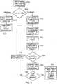
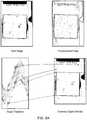
- Figures 6A and 6Bshow examples of the method shown in Figure 4 applied to the rectilinear and curvilinear coverslips, respectively.
- Figures 6A and 6Bshow four images each.
- the images in the upper left cornersare the original digital image of the slides, as obtained in, for instance, step 425 of Figure 4 .
- the edges of the coverslipsmay be obvious, but to a computer system they may not be obvious.
- the images in the upper right cornersare the binary images that were generated through a thresholding technique as in, for instance, step 430 of Figure 4 . These images can be transferred to the Hough space by a transformation as in, for instance, step 610 of Figure 5 . The resulting images in the Hough space are shown in the lower left corner of Figures 6A and 6B .
- the image in the Hough spacecan be analyzed as outlined in steps 610-620 (rectilinear coverslip) or steps 710-790 (circular coverslip).
- the images in the lower right corners of Figures 6A and 6Bshow the identification of the coverslip edges.
- the peak coordinates in Hough space(the images in the lower left corners) can be converted back to the lines in the original image space, thus identifying the edges of the coverslips, which, in turn, may bound the regions of interest for the colonies detection.
- the imagescan be enhanced by eliminating coverslip edges and mounting compound from the image.
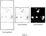
- Figure 7illustrates an application of the method shown in Figure 4 .
- the leftmost imageshows a slide with the rectangular coverslip. This image may be an input slide generated in step 425 of Figure 4 .
- the middle image in Figure 7shows the region of the slide that corresponds to the coverslip area. All pixel values outside of the coverslip area are set to zero, and thus excluded from the subsequent analysis.
- the middle imagemay be generated in step 445 of Figure 4 .
- the rightmost image in Figure 7shows detected colonies in a binary image, as in step 455 of Figure 4 . After the colonies are detected, the metaphase detection and assigning each metaphase to a colony can be performed, as in steps 485 and 490 of Figure 4 .
- the embodiments of the present inventionare also applicable to any slide analysis system to: identify where cells are located on the sample slide; identify the area where the system should perform focus mapping for accurate scanning; minimize high magnification scan time, and maximize system throughput by concentrating only on the areas where cells are present.
- rectilinear and curvilinear coverslip edge detectionsare described in detail above, other coverslip shapes may also be detected using the embodiments of the present invention.
Landscapes
- Engineering & Computer Science (AREA)
- Physics & Mathematics (AREA)
- Health & Medical Sciences (AREA)
- General Physics & Mathematics (AREA)
- Life Sciences & Earth Sciences (AREA)
- Theoretical Computer Science (AREA)
- Computer Vision & Pattern Recognition (AREA)
- Biomedical Technology (AREA)
- General Health & Medical Sciences (AREA)
- Molecular Biology (AREA)
- Chemical & Material Sciences (AREA)
- Immunology (AREA)
- Hematology (AREA)
- Urology & Nephrology (AREA)
- Analytical Chemistry (AREA)
- Medicinal Chemistry (AREA)
- Biotechnology (AREA)
- Biochemistry (AREA)
- Microbiology (AREA)
- Cell Biology (AREA)
- Pathology (AREA)
- Optics & Photonics (AREA)
- Food Science & Technology (AREA)
- Tropical Medicine & Parasitology (AREA)
- Multimedia (AREA)
- Medical Informatics (AREA)
- Nuclear Medicine, Radiotherapy & Molecular Imaging (AREA)
- Radiology & Medical Imaging (AREA)
- Quality & Reliability (AREA)
- Image Processing (AREA)
- Image Analysis (AREA)
Description
- The present invention relates generally to automated microscopy, and more specifically to improvements in the automatic detection of cell colonies' locations on a glass sample slide. Additionally, the glass sample slide may be covered with a coverslip that protects cell colonies from contamination and damage. The coverslip area is that area of a specimen slide where most of focus mapping, image capture and image analysis needs to take place, because cell colonies reside underneath the coverslip. Thus the edges of the coverslip, which denote the area of interest for automated microscopy, need to be reliably detected.
- At the present, operators typically scan and analyze the entire slide even though colonies of interest may reside only on several isolated spots within the slide. Operators are required to manually identify colonies (by drawing around them) resulting in slow system throughput. Furthermore, focus mapping can be slow or inaccurate due to sparse cell populations on colony slides.
- Some existing methods attempt automated cell analysis of biological specimens by detecting candidate objects. Each slide is first scanned at a low microscope magnification. Candidate objects are identified based on their colour, size, and shape; and their location is recorded. The candidate objects are then scanned with higher magnification lens. Thresholding and focusing steps are performed, followed by the morphological processing to identify candidate objects of interest by comparing optical features of the candidate object of interest to a target blob. However, those methods do not use morphological methods that enhance the image of the colonies of interest, neither do they associate the metaphases with the colonies. They also do not disclose a coverslip detection.
- Some other existing methods create a composite image from smaller images. Subsequent image analysis is performed only over the areas of interest within the composite image. Those methods also eliminate the edges that were created by the overlaps or similar imperfections between the subimages caused by mechanical alignment errors. Substantially, those methods could be viewed as bandwidth saving methods. They do not disclose background subtraction, morphological methods for colony detection, thresholding, association of metaphases with the colonies, or the coverslip detection.
- An accurate identification of the edges of a coverslip on a sample slide continues to be a challenge. Presently, detection methods typically scan and analyze the entire slide, i.e. the areas under and outside of the coverslip, which can be inefficient and time-consuming. Or to reduce scan and analysis time the operators need to accurately place the coverslip in the same position on each slide so that a fixed scan area is applicable to all slides.
- Some methods for detecting a microscope slide coverslip are known. For example, these methods can detect the coverslip by locating all four coverslip edges when those edges satisfy a set of predetermined criteria. However, those methods are rule-based and time consuming, and are not applicable to detecting a coverslip of unknown size and location.
- Yet some other methods use non-linear Hough transforms to detect some features of the cell or objects within the cell (e.g., detecting nucleus centre plasma membrane, etc.). Those methods also use an adjustment of the pixel intensity level to improve feature accuracy, presumably on the suspect edges of the objects of interest. However, those methods detect a of the objects within the cell, but not their precise outline, nor do they detect the edges of the coverslip.
- Some other methods detect objects that are similarly shaped using a pre-existing shape library or they detect a grid-like arranged specimens on a slide using Hough transformation. The centroids of the specimen are detected using 2D peak detection algorithms. Column and row orientations are detected followed by the calculation of the overall grid intersection locations. The methods can identify the specimens by finding their expected location in the 2D grid. However, those methods do not detect edges of the object (i.e. coverslip edges), neither do they perform any image enhancements, such as, for example, dark field subtraction.
- There is therefore a need for systems and methods that accurately and automatically detect the location of the coverslip on a microscope slide as well as the location of cell colonies of interest underneath the coverslip.
WO 2008/118886 A1 discloses identification of coverslip boundaries on a slide by detecting the coverslip's straight line edges using a Hough transform method.- A method of efficient imaging of microscopic structures by first looking at the entire specimen with a low power objective and subsequently looking at the areas of interest with a higher power objective is disclosed in Chapter 1 (The Coming Age of Virtual Microscopy: Current Technologies and Their Applications) of Virtual Microscopy and Virtual Slides in Teaching, Diagnosis, and Research by J. Gu and R. Ogilvie. This chapter teaches to scan the entire slide in order to obtain the entire image of the specimen without giving details about how to ensure that the entire slide is scanned. Further, it teaches a manual selection of location of interest without any processing that can speed up such selection.
- The present invention provides a method and an apparatus for an automatic detection of cell colonies as set out in the accompanying claims, in particular under the coverslip of a specimen slide. Slide scanning can be performed using an automated microscope with motorized axes. Multiple sub-images of the slide can be acquired with a CCD camera, followed by joining the sub-images into a composite image representing the entire scanned area. A focus map can be determined over potential locations of the cell colonies of interest. The location of the colonies can be determined by image analysis, which is followed by automatically finding metaphase cells and associating them with each colony. The invention also provides an automated, Hough-transform-based method for identifying the location of the slide coverslip and, if desired, for subtracting the coverslip edge and mounting compound image off the digital image of the slide.
- For a further understanding of the nature and advantages of the invention, reference should be made to the following description taken in conjunction with the accompanying figures. It is to be expressly understood, however, that each of the figures is provided for the purpose of illustration and description only and is not intended as a definition of the limits of the present invention.
Figure 1A schematically illustrates a microscope system for capturing images of a sample.Figure 1B schematically illustrates the microscope system ofFigure 1A connected to a server and network.Figure 2 schematically illustrates a general purpose computer.Figure 3 schematically illustrates medical imaging devices being connected to a hospital computer network.Figure 4 shows a flowchart of a method for the detection of colonies on a slide.Figure 5 shows a flowchart of a method for detection of the coverslip edge.Figures 6A and6B illustrate a Hough transform based coverslip edge detection for the rectangular and circular coverslips, respectively.Figure 7 illustrates colonies detection on a slide.- The embodiments of the present invention can be used to automatically detect the location of cell colonies on a specimen slide, as a precursor to automatically finding metaphase cells and associating them with each colony. The location of the colonies is determined by image analysis. The image can be generated by scanning a slide on an automated microscope with motorized x, y and z axes, capturing images at multiple positions with a CCD camera and stitching these images into a mosaic representing the entire scanned area. The embodiments of the present invention may also use a Hough transform to identify the position of coverslips over the specimen slides, whereby the search for the colonies can be limited to the area under the coverslip.
Figure 1A schematically illustrates a microscope system for capturing images of a sample. Themicroscope unit 10 captures digital images of a sample under investigation and the digital images are transferred tocomputer 12 where they are stored. Themicroscope unit 10 can illuminate the slide with white light for the capturing of bright field digital images, and can also illuminate the slide with a range of specific wavelengths by means of a filter set for the excitation of particular fluorescent emissions.- In some embodiments the slide holding the sample may be loaded manually by a user, but in the illustrated example the
microscope unit 10 includes a set of microscope slide racks and an automated slide loader, so that a series of slides may be selected, positioned under the microscope, imaged and returned to the slide racks. - Furthermore, in the illustrated embodiment the
computer 12 sends commands to themicroscope unit 10 dictating which slides should be imaged, what magnifications they should be imaged at, which light source should be used to illuminate each slide, and so on. Once a series of captured images has been transferred frommicroscope unit 10 tocomputer 12, auser operating computer 12 may then examine those images, perform analysis on them, and so on. The example system illustrated is representative of the Ariol® imaging system produced by Applied Imaging corporation Genetix. Figure 1B schematically illustrates the microscope system ofFigure 1A connected to aserver 14 and a network. The network consists of bothcomputing devices 16 connected locally to theserver 14, and ofcomputing devices 18 located remote from theserver 14, for example in a local area network (LAN) or via the internet. In the arrangement illustrated inFigure 1B the captured images taken bymicroscope unit 10 are uploaded fromcomputer 12 to theserver 14, such that any of theother computing devices server 14 may also view those captured images, perform analysis on them etc.Figure 2 schematically illustrates a general purpose computer system 22 (such ascomputers Figures 1A and 1B ) configured to process captured images in accordance with an embodiment of the invention. Thecomputer 22 includes a central processing unit (CPU) 24, a read only memory (ROM) 26, a random access memory (RAM) 28, a hard disk drive (HDD) 30, adisplay driver 32 anddisplay 34, and a user input/output (I/O)circuit 36 with akeyboard 38 andmouse 40. These devices are connected via acommon bus 42. Thecomputer 22 also includes agraphics card 44 connected via thecommon bus 42. The graphics card includes a graphics processing unit (GPU) and random access memory tightly coupled to the GPU (GPU memory) (not shown inFigure 2 ).- The
CPU 24 may execute program instructions stored in theROM 26, in theRAM 28 or on thehard disk drive 30 to carry out processing of captured images, for which associated data may be stored within theRAM 28 or thehard disk drive 30. TheRAM 28 andhard disk drive 30 are collectively referred to as the system memory. The GPU may also execute program instructions to carry out processing of captured image data passed to it from the CPU. Figure 3 shows medical imaging devices and a computer network which can be used in conjunction with embodiments of the invention. Thenetwork 150 includes a local area network in ahospital 152. Thehospital 152 is equipped with a number ofworkstations 154 which have access, via a local area network, to ahospital computer server 156 having an associatedstorage device 158. An archive is stored on thestorage device 158 so that data in the archive can be accessed from any of theworkstations 154. One or more of theworkstations 154 has access to a graphics card and to software for computer implementation of methods of client-side multi-component image composition as described hereinafter. The software may be stored locally at eachworkstation 154, or may be stored remotely and downloaded over thenetwork 150 to aworkstation 154 when needed. Also, a number ofmedical imaging devices hospital computer server 156 and imaging data collected with thedevices storage device 156. Of particular interest in the context of the present invention are the captured images frommicroscope unit 162. The local area network is connected to theinternet 168 by ahospital internet server 170, which allows remote access to the PACS archive. This is of use for remote accessing of data and for transferring data between hospitals, for example, if a patient is moved, or to allow external research to be undertaken. One example use would be for a clinician to access and review sample images, such as a pathologist with tissue sample images.- Further details of an exemplary embodiment of the present invention are explained with reference to
Figures 4-5 . One of the problems in detecting colonies and associated metaphases is in deciding which slide area to analyze in detail and which to exclude from the analysis, thus reducing processing time and the possibility of making identification mistakes. Figure 4 shows a flow chart of a method for image acquisition and colony detection according to one embodiment of the present invention. Such a method may be computer-implemented and may be a part of an apparatus as shown and described inFigures 1-3 above. The method of the present invention can be implemented as a part of software suite provided by the assignee of the present patent application, for example, the assignee's Cytogenetics software, which is a part of the assignee's CytoVision Systems, within which the invention may be embodied. Such a software suite can also be used as a part of the assignee's Ariol Image Capturing System within which the invention may be embodied. The Ariol Image Capturing System is a high throughput automated image analysis system for the quantification of biomarkers on microscope slides in research, clinical, pharmaceutical, genomic, and proteomic applications. Capable of both brightfield and fluorescent imaging, it rapidly scans and quantifies IHC, FISH, Immunofluorescence, Micrometastasis, Angiogenesis, DNA Ploidy, and Tissue Micro Array slides. Ariol is FDA cleared for in vitro diagnostic use of HER-2/neu, ER, and PR IHC and the detection of micrometastases in bone marrow. In addition to the systems described above, alternative devices that may be used to generate the image of the entire scanned area include, for example, a linescan camera.- At
step 405 digital images of a specimen slide are acquired by, for example, a CCD camera. Multiple sub-area of the specimen can be imaged using a low power objective digital camera with a fixed calibrated focus. A linescan camera can be used instead of the CCD camera. - At
step 410 The background intensity image can be estimated by morphologically closing the image with a small structuring element to remove noise and then morphologically opening the result with a large structuring element to remove large objects and leave only the background. The operations described here refer to grey value morphology performed over greyscale images. Closing is the process of image dilation followed by image erosion. For dilation, a chosen structuring element, for instance a 3x3 pixel matrix, is marched over the input image. The image pixel corresponding to the centre of the pixel matrix is replaced by the pixel of maximum intensity in the pixel matrix. Thus, when dilation is applied, bright objects appear to grow while the darker holes in the object tend to shrink. Erosion works in a manner opposite from dilation. When erosion is applied to a grey scale image, bright objects shrink in size, and dark holes within those objects become larger. The effect of greyscale morphological closing is to eliminate unwanted dark regions in the image smaller than the structuring element, while preserving bright regions. Conversely, the effect of morphological opening eliminates bright regions in the image smaller than the structuring element, while preserving dark regions. A person skilled in the art of digital image processing would know of many structuring element shapes and sizes, and many combinations of erosion and dilation to achieve the desired result. For example, a 3x3 pixel matrix can be used as a small element, while 15x15 pixel matrix can be used as a large element. - At step 415 the original image of the slide is compared with the background intensity image. The minimum of the original image and the background intensity image can be subtracted from the original image to eliminate variation in illumination across the slide.
- At
step 420 background subtracted images are shrunk down by a predefined scale factor. For example, a predefined scale factor of 50 may be used. The shrunken images can be stitched together instep 425. Thus, a single mosaic image representing the entire scan area can be created, and yet have a manageable file size. - At step 430 the mosaic image is converted into a binary image by automatic thresholding based on analysis of the grey level gradients around the modal grey level of the mosaic image. First, the modal grey level in the image (m) is calculated by analysis of the histogram of the image. Then, for each pixel in the image, the maximum gray level gradient (g) is calculated as the maximum gray level difference between the pixel and its neighbours:

- The gradients from equation 1.1 are summed for all pixels in the image to calculate the sum Sg. Similarly, for each pixel in the image, the gradient is multiplied by the pixel's grey value, and summed for all pixels in the image to calculate sum Sgi. Then, the threshold can be estimated as:

- The threshold calculation can be made more robust by considering only the pixels with grey value above m and below m+(range/5), where range is the difference between the maximum and minimum grey levels in the image. Many other thresholding techniques, known to a person skilled in the arts, may also be used.
- At step 435 a decision is made whether to perform coverslip detection. The preferred technique for identification of the coverslip is image analysis using Hough transforms to identify edges of the coverslip, details of which are described in relation to
Figure 5 . The coverslip area may bound the area of interest for the colony detection, for the cases where the cell colonies are only present underneath the coverslip. For instance, once the location of a coverslip is detected, all the pixel values outside of the coverslip area can be set to zero, as shown atstep 445. When the pixels in an area of image have a uniform zero value that area does not have to be searched for the colonies in the subsequent processing steps, thus the time required for colonies identification and a possibility of making colony identification mistakes can be reduced. - At
step 450 the binary mosaic image is enhanced by morphological processing: closing followed by opening. Morphological image processing techniques can be useful for extracting image components that may better represent and describe region shapes. This operation joins interphase cells visible in the mosaic into clusters. - At
step 455 colonies (e.g., clusters) in the binary image are identified via image analysis (e.g., region detection). Many detection methods may be used. For example, automatic size measurements may be performed on the identified objects. Wanted objects may be those having a size between a predetermined minimum and maximum number of pixels. Unwanted objects can be eliminated atstep 460 based on their size and/or morphology, thus reducing the processing time and the possibility of making colony identification mistakes in the subsequent steps. - At
step 465 the position, size, and binary image mask are recorded for the colonies that remained after the elimination done atstep 460. The subsequent processing steps can ignore empty spaces between the recorded colonies of interest, thus further saving the processing time. - At step 470 a switch is made to a higher power objective (e.g. 10x or 20x) for the subsequent colony image acquisition.
- At
step 475 the recorded colonies positions fromstep 465 are used as the basis for a focus map, i.e. automatic focusing is only performed where there are identified colonies. Large empty spaces among the colonies can be ignored, thus minimizing the time required to produce a focus map. - At
step 480 the slide is scanned again with a higher power objective using the focus map derived instep 475. If the coverslip detection as instep 440 has been performed, the scan area for subsequent analysis can be reduced to that defined by the coverslip. The scan area can also be reduced to the bounding box around the recorded colonies. - At
step 485 for each high power image frame metaphase detection is performed. Metaphase is a phase of cell reproduction cycle in which condensed chromosomes, carrying genetic information, align in the middle of the cell before being separated into each of the two daughter cells. The chromosomes shorten and become visible under the microscope during this phase. The visibility of the shortened chromosomes may be further enhanced by staining the cells with dyes. - At
step 490 each detected metaphase is assigned to a colony based on its proximity to the colony centre of gravity, radius and/or binary mask. Figure 5 shows a flowchart of coverslip detection according to one embodiment of the present invention. As explained above, coverslip detection may be beneficial in reducing the area of interest in the colony detections, thus reducing the slide processing time while also reducing false colonies detection. Furthermore, the area of slide image of interest can be enhanced by eliminating coverslip edges and the mounting compound from the subsequent image analysis.- At step 510 a binary edge image from step 430 of
Figure 4 is passed through a Hough transform to produce its counterpart in Hough space. A linear Hough transform for detecting straight lines, which can be used for detecting the edges of a rectilinear coverslip, is described below. - In the image space, the straight line can be written as:

- In Hough space, the characteristics of the straight line are not points x, y, but the slope parameter "m" and the intercept parameter "b." Thus, a straight line as in equation (2.1) can be represented as a point (b, m) in Hough space. However, vertical lines would give rise to unbounded values of the parameters "m" and "b." Therefore, for computational reasons it is better to parameterize the lines with two other parameters: "r" and "θ." The parameter "r" represents the distance between the line and the origin of a coordinate system, while "θ" is the angle of the vector from the origin to this closest point. Using this parameterisation, the equation of a line can be written as:

- It is therefore possible to associate each line of an image to a pair (r,θ). The (r,θ) plane can be referred to asHough space for the set of straight lines in two dimensions.
- An infinite number of lines can pass through a single point of the plane. If that point has coordinates (xo,yo) in the image plane, then all the lines that go through it obey the following equation:

- Equation (2.3) describes a sinusoidal curve in the (r,θ) plane. If the curves corresponding to two points are superimposed, the location (in the Hough space) where they cross corresponds to lines (in the original image space) that pass through both points. The Hough transform algorithm uses an array, sometimes called accumulator, to calculate the likelihood of the existence of a line y = mx + b in the image space. For each pixel and its neighbourhood, the Hough transform algorithm determines if there is enough evidence of an edge at that pixel. If so, it will calculate the parameters of that line, and then look for the accumulator's bin that the parameters fall into, and then increase the value of that bin. By finding the bins with the highest values, typically by looking for local maxima in the accumulator space, the most likely location of the lines in the image space can be found.
- Although the version of the transform described above applies to finding straight lines, a similar transform can be used for finding any shape which can be represented by a set of parameters. A circle, for instance, can be transformed into a set of three parameters, representing its centre and radius, so that the Hough space becomes three dimensional. For a circular coverslip with a known radius, Hough transform becomes a two parameter one, which can be executed following the steps as outlined above.
- Returning back to
Figure 5 , at step 520 a decision on specific processing steps for the image in Hough space is made depending on the shape of the coverslip: rectilinear or curvilinear. Although these coverslip shapes may be the most common, the method is not limited to them. - At
steps - The processing of the curvilinear coverslip with known radius R is explained with reference to steps 710 to 790. At step 710 a circle C1 with radius R is constructed in all non-zero pixels of the image.
- At step 720 point P, Q on circle C1 is selected and circle C2 having a centre in point P, Q and having radius R is constructed.
- At
step 730 point X, Y on circle C2 is identified. Next, at step 740, values of the pixels on circle C2 in the vicinity of point X, Y are identified. The pixels that are located about 5° and 10° back and forth from point X, Y can be used, but other suitable angle values may be used. - At
step 750 the values of the pixels identified in step 740 are evaluated. The non-zero values make the presence of circular coverslip centred in point P, Q more likely. Therefore, the counter associated with point P, Q in Hough space is correspondingly increased instep 760. - If the pixel values at
step 750 were zero, then at step 770 a next point P, Q on circle C1 is chosen by moving along circle C1 for about 1° away from the previous point P, Q. Next, new circle C2 is constructed in new point P, Q (as in step 720) and the identification of the most likely position of the circular coverslip can continue as shown at steps 720-750. - At step 780 a check is performed to verify whether the last point on the last circle C1 is reached. If not, then step 770 is executed again by moving along circle C1 for about 1° away from the previous point P, Q, and proceeding back to step 720. If the last step on the last circle C1 was reached, the processing is finished. The point with the highest value of pixel P, Q in Hough space can be declared the most probable location of the centre of the circular coverslip.
Figures 6A and6B show examples of the method shown inFigure 4 applied to the rectilinear and curvilinear coverslips, respectively.Figures 6A and6B show four images each. The images in the upper left corners are the original digital image of the slides, as obtained in, for instance, step 425 ofFigure 4 . To a human observer the edges of the coverslips may be obvious, but to a computer system they may not be obvious.- The images in the upper right corners are the binary images that were generated through a thresholding technique as in, for instance, step 430 of
Figure 4 . These images can be transferred to the Hough space by a transformation as in, for instance, step 610 ofFigure 5 . The resulting images in the Hough space are shown in the lower left corner ofFigures 6A and6B . The image in the Hough space can be analyzed as outlined in steps 610-620 (rectilinear coverslip) or steps 710-790 (circular coverslip). - The images in the lower right corners of
Figures 6A and6B show the identification of the coverslip edges. Using the reverse Hough transform, the peak coordinates in Hough space (the images in the lower left corners) can be converted back to the lines in the original image space, thus identifying the edges of the coverslips, which, in turn, may bound the regions of interest for the colonies detection. Furthermore, the images can be enhanced by eliminating coverslip edges and mounting compound from the image. Figure 7 illustrates an application of the method shown inFigure 4 . The leftmost image shows a slide with the rectangular coverslip. This image may be an input slide generated instep 425 ofFigure 4 . The middle image inFigure 7 shows the region of the slide that corresponds to the coverslip area. All pixel values outside of the coverslip area are set to zero, and thus excluded from the subsequent analysis. The middle image may be generated instep 445 ofFigure 4 . The rightmost image inFigure 7 shows detected colonies in a binary image, as instep 455 ofFigure 4 . After the colonies are detected, the metaphase detection and assigning each metaphase to a colony can be performed, as insteps Figure 4 .- While the above invention is described in conjunction with a high throughput image capturing system, the embodiments of the present invention are also applicable to any slide analysis system to: identify where cells are located on the sample slide; identify the area where the system should perform focus mapping for accurate scanning; minimize high magnification scan time, and maximize system throughput by concentrating only on the areas where cells are present. Furthermore, while rectilinear and curvilinear coverslip edge detections are described in detail above, other coverslip shapes may also be detected using the embodiments of the present invention.


Claims (9)
- A method for an automatic detection of cell colonies, comprising:acquiring lower magnification digital images of sub-areas of a slide using a low power objective (405);generating background intensity images (410) by grey value morphologically processing the acquired images by a closing followed by an opening;forming background-subtracted sub-area images by subtracting the minimum of a background intensity image and the original image from the original image (415);generating shrunk sub-area images by shrinking the background-subtracted sub-area images by a predefined scale factor (420);stitching the shrunk sub-area images into a composite image representing the entire slide (425);converting the composite image into a binary edge image by the application of an automatic thresholding technique (430) based on analysis of grey level gradients;passing the binary edge image through a Hough transform to produce a Hough space transformed image (440);analyzing the Hough space transformed image to identify peaks representing a coverslip edge location (440);subjecting the Hough space transformed image to an inverse Hough transform to convert said peaks back to the edges of the coverslip in the binary edge image (440);setting to zero all pixels of the composite image outside of the coverslip area (445);morphologically processing the composite binary edge image by closing followed by opening (450);identifying colonies in the composite binary edge image (455);eliminating unwanted colonies from the composite binary edge image based on their size or morphology (460);recording the location, size, or binary image masks of the remaining colonies on the slide (465);generating a map of automatic focusing values over the remaining colonies on the slide using a high power objective (470, 475);acquiring a plurality of higher magnification images over the remaining colonies on the slide using a high power objective and the map of automatic focusing values (480);performing metaphase detection (485); andassigning each detected metaphase to a colony (490).
- The method of claim 1 wherein said lower and higher magnification digital images are acquired by a digital camera with the low and high power objectives at a fixed calibrated focus.
- The method of claim 2 wherein said digital camera is a CCD camera.
- The method of claim 2 or 3 wherein said low power objective has a magnification chosen from the range of 1.25 to 5.
- The method of claim 2, 3 or 4 wherein said high power objective has a magnification chosen from the range of 10 to 20.
- The method of any one of claims 1 to 5 wherein said Hough transform is a linear Hough transform configured for a rectilinear coverslip, the Hough transform is based on polar coordinates of a line, said transformed image is analyzed to identify peaks close to 90° and 180° representing horizontal and vertical lines in the binary edge image, and said transformed image is subjected to an inverse Hough transform to convert said peaks close to 90° and 180° back to horizontal and vertical lines representing the edges of the coverslip in the binary edge image.
- The method of any one of claims 1 to 5 wherein said Hough transform is configured for a curvilinear coverslip, having a circular shape with a known radius R, the Hough transform is based on a weighted circular Hough transform, said transformed image is analyzed to find the most probable locations of coverslip centres, and said transformed image is subjected to an inverse circular Hough transform to convert said most probable locations of coverslip centres back to the locations in the binary edge image.
- The method of claim 7 wherein said transformed image is analyzed to find the most probable locations of coverslip centres by:(a) treating all non-zero pixels in the binary image as the centres of a circle C1 of radius R;(b) treating each point on circle C1 as the centre P,Q of a circle C2 of radius R;(c) for each point X,Y on circle C2 stepping back about 5° and about 10° and stepping forward about 5° and about 10° starting from the point X,Y along the circle C2, and checking when the pixel at that location is non-zero in the binary image, and when it is, then incrementing the value of pixel at P,Q in the Hough space image;(d) moving to the next point on circle C1 in steps of about 1°, and repeating steps (b) and (c);(e) treating the highest value of pixel at P,Q in the Hough image as the most probable location of the centre of the circular shape coverslip.
- An apparatus for an automatic detection of cell colonies, comprising: an optical system comprising a digital camera for acquiring digital images of the slide, a computing unit for storing and processing the digital images of the slide, said computing unit configured by program instructions to execute a method according to any one of the preceding claims.
Applications Claiming Priority (3)
| Application Number | Priority Date | Filing Date | Title |
|---|---|---|---|
| US98169407P | 2007-10-22 | 2007-10-22 | |
| US98171207P | 2007-10-22 | 2007-10-22 | |
| US12/253,163US8064678B2 (en) | 2007-10-22 | 2008-10-16 | Automated detection of cell colonies and coverslip detection using hough transforms |
Publications (3)
| Publication Number | Publication Date |
|---|---|
| EP2053535A2 EP2053535A2 (en) | 2009-04-29 |
| EP2053535A3 EP2053535A3 (en) | 2012-06-27 |
| EP2053535B1true EP2053535B1 (en) | 2017-06-14 |
Family
ID=40289295
Family Applications (1)
| Application Number | Title | Priority Date | Filing Date |
|---|---|---|---|
| EP08253415.7ANot-in-forceEP2053535B1 (en) | 2007-10-22 | 2008-10-21 | Automated detection of cell colonies and coverslip detection using hough transforms |
Country Status (2)
| Country | Link |
|---|---|
| US (1) | US8064678B2 (en) |
| EP (1) | EP2053535B1 (en) |
Families Citing this family (22)
| Publication number | Priority date | Publication date | Assignee | Title |
|---|---|---|---|---|
| CN101540040B (en)* | 2008-03-21 | 2012-12-12 | 深圳迈瑞生物医疗电子股份有限公司 | Method and device for automatically detecting boundary of beam-limiting device |
| EP2376964A1 (en)* | 2008-12-19 | 2011-10-19 | Abbott Laboratories | Method and apparatus for detecting microscope slide coverslips |
| JP5786110B2 (en)* | 2009-12-11 | 2015-09-30 | ライカ バイオシステムズ イメージング インコーポレイテッドAperio Technologies, Inc. | Improvement of signal-to-noise ratio in digital pathological image analysis |
| US8508588B2 (en)* | 2010-05-19 | 2013-08-13 | General Electric Company | Methods and systems for identifying well wall boundaries of microplates |
| JP5703609B2 (en)* | 2010-07-02 | 2015-04-22 | ソニー株式会社 | Microscope and region determination method |
| CN102155919A (en)* | 2011-03-22 | 2011-08-17 | 黄晓华 | Device for detecting cells with Hough transform |
| DE102012101377B4 (en)* | 2012-02-21 | 2017-02-09 | Leica Biosystems Nussloch Gmbh | Method of preparing samples for microscopy and device for checking the cover quality of samples |
| US9041793B2 (en)* | 2012-05-17 | 2015-05-26 | Fei Company | Scanning microscope having an adaptive scan |
| US10156503B2 (en) | 2013-03-05 | 2018-12-18 | Ventana Medical Systems, Inc. | Methods and apparatuses for detecting microscope slide coverslips |
| US8885901B1 (en)* | 2013-10-22 | 2014-11-11 | Eyenuk, Inc. | Systems and methods for automated enhancement of retinal images |
| EP3108407A4 (en)* | 2014-02-17 | 2018-02-14 | General Electric Company | Method and system for processing scanned images |
| US10564172B2 (en) | 2014-05-08 | 2020-02-18 | The Cleveland Clinic Foundation | Systems and methods for detection, analysis, isolation and/or harvesting of biological objects |
| CN104966282B (en)* | 2014-12-24 | 2017-12-08 | 广西师范大学 | A kind of image-pickup method and system for single blood erythrocyte by mocro detection |
| EP3499459A1 (en)* | 2017-12-18 | 2019-06-19 | FEI Company | Method, device and system for remote deep learning for microscopic image reconstruction and segmentation |
| CN108764171A (en)* | 2018-05-31 | 2018-11-06 | 四川斐讯信息技术有限公司 | A kind of recognition methods of stitching image and system |
| DE102019113540A1 (en)* | 2019-05-21 | 2020-11-26 | Carl Zeiss Microscopy Gmbh | Light microscope with automatic focusing |
| EP3839596B1 (en) | 2019-12-20 | 2023-08-23 | Euroimmun Medizinische Labordiagnostika AG | Device and method for identification of covering glass areas of an object holder |
| CN112541405B (en)* | 2020-11-27 | 2024-07-19 | 陕西海泰电子有限责任公司 | Automatic identification method for nonlinear double-frequency chart |
| CN112884784B (en)* | 2021-03-11 | 2024-06-04 | 南通大学 | Image-based lens detection and front and back judgment method |
| CN113866437A (en)* | 2021-09-29 | 2021-12-31 | 山东云旗信息科技有限公司 | Method and system for positioning, identifying and slicing medical slides |
| CN117994347B (en)* | 2024-04-07 | 2024-06-11 | 宝鸡市鹏盛鑫有色金属有限责任公司 | High-precision positioning method for flange machining drilling |
| CN119048605B (en)* | 2024-10-31 | 2024-12-27 | 大连通翼科技有限公司 | Visual positioning method for coal pile area on surface of coal mine conveyor belt |
Family Cites Families (8)
| Publication number | Priority date | Publication date | Assignee | Title |
|---|---|---|---|---|
| US5978497A (en)* | 1994-09-20 | 1999-11-02 | Neopath, Inc. | Apparatus for the identification of free-lying cells |
| US5638459A (en)* | 1994-09-20 | 1997-06-10 | Neopath, Inc. | Method and apparatus for detecting a microscope slide coverslip |
| WO2003067904A2 (en)* | 2002-02-06 | 2003-08-14 | University Of North Carolina At Chapel Hill | High-throughput cell identification and isolation method and apparatus |
| US7738730B2 (en)* | 2006-01-25 | 2010-06-15 | Atalasoft, Inc. | Method of image analysis using sparse hough transform |
| JP5244801B2 (en)* | 2006-09-22 | 2013-07-24 | アーエルエス アウトメーテッド ラブ ソルーションズ ゲーエムベーハー | Method and apparatus for automated removal of cells and / or cell colonies |
| WO2008118886A1 (en)* | 2007-03-23 | 2008-10-02 | Bioimagene, Inc. | Digital microscope slide scanning system and methods |
| US8417011B2 (en)* | 2008-09-18 | 2013-04-09 | Molecular Devices (New Milton) Ltd. | Colony detection |
| EP2376964A1 (en)* | 2008-12-19 | 2011-10-19 | Abbott Laboratories | Method and apparatus for detecting microscope slide coverslips |
- 2008
- 2008-10-16USUS12/253,163patent/US8064678B2/enactiveActive
- 2008-10-21EPEP08253415.7Apatent/EP2053535B1/ennot_activeNot-in-force
Non-Patent Citations (3)
| Title |
|---|
| GU AND V ANDERSON J ED - GU & OGILVIE: "Development of a virtual telemicroscope", 22 June 2005, VIRTUAL MICROSCOPY AND VIRTUAL SLIDES IN TEACHING, DIAGNOSIS, AND RESEARCH, CRC PRESS, PAGE(S) 61 - 76, ISBN: 978-0-8493-2067-5, XP007922382* |
| JIANG GU AND ROBERT OGILVIE ED - JIANG GU ET AL: "The Coming Age of Virtual microscopy", 22 June 2005, VIRTUAL MICROSCOPY AND VIRTUAL SLIDES IN TEACHING, DIAGNOSIS, AND RESEARCH, CRC PRESS, PAGE(S) 1 - 6, ISBN: 978-0-8493-2067-5, XP007922381* |
| PERKINELMER: "AutoIMAGE FT-IR Microscope System Workhorse system for high quality and dependable results", 20050101, 1 January 2005 (2005-01-01), pages 1 - 4, XP007922383* |
Also Published As
| Publication number | Publication date |
|---|---|
| US20090129660A1 (en) | 2009-05-21 |
| EP2053535A2 (en) | 2009-04-29 |
| EP2053535A3 (en) | 2012-06-27 |
| US8064678B2 (en) | 2011-11-22 |
Similar Documents
| Publication | Publication Date | Title |
|---|---|---|
| EP2053535B1 (en) | Automated detection of cell colonies and coverslip detection using hough transforms | |
| US20220260826A1 (en) | Computational microscopy based-system and method for automated imaging and analysis of pathology specimens | |
| EP3811287B1 (en) | System and method for detection and classification of objects of interest in microscope images by supervised machine learning | |
| EP3186778B1 (en) | System and method for calculating focus variation for a digital microscope | |
| CA2610298C (en) | System and method for re-locating an object in a sample on a slide with a microscope imaging device | |
| EP4220564A2 (en) | Image processing systems and methods for displaying multiple images of a biological specimen | |
| US5978498A (en) | Apparatus for automated identification of cell groupings on a biological specimen | |
| CN111275016A (en) | Slide scanning image acquisition and analysis method and device | |
| WO2011146006A1 (en) | Methods and systems for identifying well wall boundaries of microplates | |
| JP2013526717A5 (en) | ||
| EP1680757A1 (en) | Automated microspcope slide tissue sample mapping and image acquisition | |
| WO2009145723A1 (en) | System and method for detecting and eliminating one or more defocused or low contrast-to-noise ratio images | |
| CN112464802B (en) | Automatic identification method and device for slide sample information and computer equipment | |
| EP3837664A1 (en) | Generating annotation data of tissue images | |
| US8064679B2 (en) | Targeted edge detection method and apparatus for cytological image processing applications | |
| CN113785361A (en) | Chromosome automated analysis method | |
| Özdemir et al. | Automated and semi-automated enhancement, segmentation and tracing of cytoskeletal networks in microscopic images: A review | |
| CN118115496B (en) | Wafer defect detection method and device | |
| Remya et al. | Preprocessing G-banded metaphase: towards the design of automated karyotyping | |
| Tan et al. | Simple landscapes analysis for relevant regions detection in breast carcinoma histopathological images | |
| Mabrouk et al. | Automated statistical and morphological based gridding methods for noisy microarray image processing | |
| Mandal et al. | Automated histopathological image analysis: a review on ROI extraction | |
| US12432437B2 (en) | Method and system for event-based imaging | |
| Bonam et al. | Toward automated quantification of biological microstructures using unbiased stereology | |
| Poon | Algorithms for detecting and segmenting nucleated blood cells |
Legal Events
| Date | Code | Title | Description |
|---|---|---|---|
| PUAI | Public reference made under article 153(3) epc to a published international application that has entered the european phase | Free format text:ORIGINAL CODE: 0009012 | |
| AK | Designated contracting states | Kind code of ref document:A2 Designated state(s):AT BE BG CH CY CZ DE DK EE ES FI FR GB GR HR HU IE IS IT LI LT LU LV MC MT NL NO PL PT RO SE SI SK TR | |
| AX | Request for extension of the european patent | Extension state:AL BA MK RS | |
| RAP1 | Party data changed (applicant data changed or rights of an application transferred) | Owner name:GENETIX CORPORATION | |
| PUAL | Search report despatched | Free format text:ORIGINAL CODE: 0009013 | |
| RIC1 | Information provided on ipc code assigned before grant | Ipc:G06K 9/00 20060101AFI20120426BHEP Ipc:G06T 7/00 20060101ALI20120426BHEP Ipc:G01N 33/48 20060101ALI20120426BHEP Ipc:G02B 21/36 20060101ALI20120426BHEP | |
| AK | Designated contracting states | Kind code of ref document:A3 Designated state(s):AT BE BG CH CY CZ DE DK EE ES FI FR GB GR HR HU IE IS IT LI LT LU LV MC MT NL NO PL PT RO SE SI SK TR | |
| AX | Request for extension of the european patent | Extension state:AL BA MK RS | |
| RIC1 | Information provided on ipc code assigned before grant | Ipc:G06K 9/00 20060101AFI20120521BHEP Ipc:G06T 7/00 20060101ALI20120521BHEP Ipc:G01N 33/48 20060101ALI20120521BHEP Ipc:G02B 21/36 20060101ALI20120521BHEP | |
| 17P | Request for examination filed | Effective date:20121213 | |
| AKX | Designation fees paid | Designated state(s):AT BE BG CH CY CZ DE DK EE ES FI FR GB GR HR HU IE IS IT LI LT LU LV MC MT NL NO PL PT RO SE SI SK TR | |
| 17Q | First examination report despatched | Effective date:20131128 | |
| RAP1 | Party data changed (applicant data changed or rights of an application transferred) | Owner name:LEICA BIOSYSTEMS RICHMOND INC. | |
| RAP1 | Party data changed (applicant data changed or rights of an application transferred) | Owner name:LEICA BIOSYSTEMS IMAGING INC. | |
| STAA | Information on the status of an ep patent application or granted ep patent | Free format text:STATUS: EXAMINATION IS IN PROGRESS | |
| REG | Reference to a national code | Ref country code:DE Ref legal event code:R079 Ref document number:602008050659 Country of ref document:DE Free format text:PREVIOUS MAIN CLASS: G06K0009000000 Ipc:G02B0021340000 | |
| GRAP | Despatch of communication of intention to grant a patent | Free format text:ORIGINAL CODE: EPIDOSNIGR1 | |
| STAA | Information on the status of an ep patent application or granted ep patent | Free format text:STATUS: GRANT OF PATENT IS INTENDED | |
| INTG | Intention to grant announced | Effective date:20170210 | |
| RIC1 | Information provided on ipc code assigned before grant | Ipc:G01N 33/50 20060101ALI20170131BHEP Ipc:G06T 7/00 20170101ALI20170131BHEP Ipc:G01N 33/48 20060101ALI20170131BHEP Ipc:G02B 21/34 20060101AFI20170131BHEP Ipc:G06K 9/00 20060101ALI20170131BHEP Ipc:G02B 21/36 20060101ALI20170131BHEP | |
| GRAS | Grant fee paid | Free format text:ORIGINAL CODE: EPIDOSNIGR3 | |
| GRAA | (expected) grant | Free format text:ORIGINAL CODE: 0009210 | |
| STAA | Information on the status of an ep patent application or granted ep patent | Free format text:STATUS: THE PATENT HAS BEEN GRANTED | |
| AK | Designated contracting states | Kind code of ref document:B1 Designated state(s):AT BE BG CH CY CZ DE DK EE ES FI FR GB GR HR HU IE IS IT LI LT LU LV MC MT NL NO PL PT RO SE SI SK TR | |
| REG | Reference to a national code | Ref country code:GB Ref legal event code:FG4D | |
| REG | Reference to a national code | Ref country code:CH Ref legal event code:EP Ref country code:AT Ref legal event code:REF Ref document number:901508 Country of ref document:AT Kind code of ref document:T Effective date:20170615 | |
| REG | Reference to a national code | Ref country code:IE Ref legal event code:FG4D | |
| REG | Reference to a national code | Ref country code:DE Ref legal event code:R096 Ref document number:602008050659 Country of ref document:DE | |
| REG | Reference to a national code | Ref country code:NL Ref legal event code:MP Effective date:20170614 | |
| REG | Reference to a national code | Ref country code:FR Ref legal event code:PLFP Year of fee payment:10 | |
| REG | Reference to a national code | Ref country code:LT Ref legal event code:MG4D | |
| PG25 | Lapsed in a contracting state [announced via postgrant information from national office to epo] | Ref country code:FI Free format text:LAPSE BECAUSE OF FAILURE TO SUBMIT A TRANSLATION OF THE DESCRIPTION OR TO PAY THE FEE WITHIN THE PRESCRIBED TIME-LIMIT Effective date:20170614 Ref country code:ES Free format text:LAPSE BECAUSE OF FAILURE TO SUBMIT A TRANSLATION OF THE DESCRIPTION OR TO PAY THE FEE WITHIN THE PRESCRIBED TIME-LIMIT Effective date:20170614 Ref country code:GR Free format text:LAPSE BECAUSE OF FAILURE TO SUBMIT A TRANSLATION OF THE DESCRIPTION OR TO PAY THE FEE WITHIN THE PRESCRIBED TIME-LIMIT Effective date:20170915 Ref country code:LT Free format text:LAPSE BECAUSE OF FAILURE TO SUBMIT A TRANSLATION OF THE DESCRIPTION OR TO PAY THE FEE WITHIN THE PRESCRIBED TIME-LIMIT Effective date:20170614 Ref country code:NO Free format text:LAPSE BECAUSE OF FAILURE TO SUBMIT A TRANSLATION OF THE DESCRIPTION OR TO PAY THE FEE WITHIN THE PRESCRIBED TIME-LIMIT Effective date:20170914 Ref country code:HR Free format text:LAPSE BECAUSE OF FAILURE TO SUBMIT A TRANSLATION OF THE DESCRIPTION OR TO PAY THE FEE WITHIN THE PRESCRIBED TIME-LIMIT Effective date:20170614 | |
| REG | Reference to a national code | Ref country code:AT Ref legal event code:MK05 Ref document number:901508 Country of ref document:AT Kind code of ref document:T Effective date:20170614 | |
| PG25 | Lapsed in a contracting state [announced via postgrant information from national office to epo] | Ref country code:LV Free format text:LAPSE BECAUSE OF FAILURE TO SUBMIT A TRANSLATION OF THE DESCRIPTION OR TO PAY THE FEE WITHIN THE PRESCRIBED TIME-LIMIT Effective date:20170614 Ref country code:SE Free format text:LAPSE BECAUSE OF FAILURE TO SUBMIT A TRANSLATION OF THE DESCRIPTION OR TO PAY THE FEE WITHIN THE PRESCRIBED TIME-LIMIT Effective date:20170614 Ref country code:NL Free format text:LAPSE BECAUSE OF FAILURE TO SUBMIT A TRANSLATION OF THE DESCRIPTION OR TO PAY THE FEE WITHIN THE PRESCRIBED TIME-LIMIT Effective date:20170614 Ref country code:BG Free format text:LAPSE BECAUSE OF FAILURE TO SUBMIT A TRANSLATION OF THE DESCRIPTION OR TO PAY THE FEE WITHIN THE PRESCRIBED TIME-LIMIT Effective date:20170914 | |
| PG25 | Lapsed in a contracting state [announced via postgrant information from national office to epo] | Ref country code:AT Free format text:LAPSE BECAUSE OF FAILURE TO SUBMIT A TRANSLATION OF THE DESCRIPTION OR TO PAY THE FEE WITHIN THE PRESCRIBED TIME-LIMIT Effective date:20170614 Ref country code:RO Free format text:LAPSE BECAUSE OF FAILURE TO SUBMIT A TRANSLATION OF THE DESCRIPTION OR TO PAY THE FEE WITHIN THE PRESCRIBED TIME-LIMIT Effective date:20170614 Ref country code:CZ Free format text:LAPSE BECAUSE OF FAILURE TO SUBMIT A TRANSLATION OF THE DESCRIPTION OR TO PAY THE FEE WITHIN THE PRESCRIBED TIME-LIMIT Effective date:20170614 Ref country code:SK Free format text:LAPSE BECAUSE OF FAILURE TO SUBMIT A TRANSLATION OF THE DESCRIPTION OR TO PAY THE FEE WITHIN THE PRESCRIBED TIME-LIMIT Effective date:20170614 Ref country code:EE Free format text:LAPSE BECAUSE OF FAILURE TO SUBMIT A TRANSLATION OF THE DESCRIPTION OR TO PAY THE FEE WITHIN THE PRESCRIBED TIME-LIMIT Effective date:20170614 | |
| PG25 | Lapsed in a contracting state [announced via postgrant information from national office to epo] | Ref country code:IT Free format text:LAPSE BECAUSE OF FAILURE TO SUBMIT A TRANSLATION OF THE DESCRIPTION OR TO PAY THE FEE WITHIN THE PRESCRIBED TIME-LIMIT Effective date:20170614 Ref country code:PL Free format text:LAPSE BECAUSE OF FAILURE TO SUBMIT A TRANSLATION OF THE DESCRIPTION OR TO PAY THE FEE WITHIN THE PRESCRIBED TIME-LIMIT Effective date:20170614 Ref country code:IS Free format text:LAPSE BECAUSE OF FAILURE TO SUBMIT A TRANSLATION OF THE DESCRIPTION OR TO PAY THE FEE WITHIN THE PRESCRIBED TIME-LIMIT Effective date:20171014 | |
| REG | Reference to a national code | Ref country code:DE Ref legal event code:R097 Ref document number:602008050659 Country of ref document:DE | |
| PLBE | No opposition filed within time limit | Free format text:ORIGINAL CODE: 0009261 | |
| STAA | Information on the status of an ep patent application or granted ep patent | Free format text:STATUS: NO OPPOSITION FILED WITHIN TIME LIMIT | |
| PG25 | Lapsed in a contracting state [announced via postgrant information from national office to epo] | Ref country code:DK Free format text:LAPSE BECAUSE OF FAILURE TO SUBMIT A TRANSLATION OF THE DESCRIPTION OR TO PAY THE FEE WITHIN THE PRESCRIBED TIME-LIMIT Effective date:20170614 | |
| 26N | No opposition filed | Effective date:20180315 | |
| PG25 | Lapsed in a contracting state [announced via postgrant information from national office to epo] | Ref country code:MC Free format text:LAPSE BECAUSE OF FAILURE TO SUBMIT A TRANSLATION OF THE DESCRIPTION OR TO PAY THE FEE WITHIN THE PRESCRIBED TIME-LIMIT Effective date:20170614 | |
| REG | Reference to a national code | Ref country code:CH Ref legal event code:PL | |
| REG | Reference to a national code | Ref country code:IE Ref legal event code:MM4A | |
| PG25 | Lapsed in a contracting state [announced via postgrant information from national office to epo] | Ref country code:CH Free format text:LAPSE BECAUSE OF NON-PAYMENT OF DUE FEES Effective date:20171031 Ref country code:LI Free format text:LAPSE BECAUSE OF NON-PAYMENT OF DUE FEES Effective date:20171031 Ref country code:LU Free format text:LAPSE BECAUSE OF NON-PAYMENT OF DUE FEES Effective date:20171021 | |
| REG | Reference to a national code | Ref country code:BE Ref legal event code:MM Effective date:20171031 | |
| PG25 | Lapsed in a contracting state [announced via postgrant information from national office to epo] | Ref country code:BE Free format text:LAPSE BECAUSE OF NON-PAYMENT OF DUE FEES Effective date:20171031 Ref country code:SI Free format text:LAPSE BECAUSE OF FAILURE TO SUBMIT A TRANSLATION OF THE DESCRIPTION OR TO PAY THE FEE WITHIN THE PRESCRIBED TIME-LIMIT Effective date:20170614 | |
| PG25 | Lapsed in a contracting state [announced via postgrant information from national office to epo] | Ref country code:MT Free format text:LAPSE BECAUSE OF NON-PAYMENT OF DUE FEES Effective date:20171021 | |
| REG | Reference to a national code | Ref country code:FR Ref legal event code:PLFP Year of fee payment:11 | |
| PG25 | Lapsed in a contracting state [announced via postgrant information from national office to epo] | Ref country code:IE Free format text:LAPSE BECAUSE OF NON-PAYMENT OF DUE FEES Effective date:20171021 | |
| PG25 | Lapsed in a contracting state [announced via postgrant information from national office to epo] | Ref country code:HU Free format text:LAPSE BECAUSE OF FAILURE TO SUBMIT A TRANSLATION OF THE DESCRIPTION OR TO PAY THE FEE WITHIN THE PRESCRIBED TIME-LIMIT; INVALID AB INITIO Effective date:20081021 | |
| PG25 | Lapsed in a contracting state [announced via postgrant information from national office to epo] | Ref country code:CY Free format text:LAPSE BECAUSE OF NON-PAYMENT OF DUE FEES Effective date:20170614 | |
| PG25 | Lapsed in a contracting state [announced via postgrant information from national office to epo] | Ref country code:TR Free format text:LAPSE BECAUSE OF FAILURE TO SUBMIT A TRANSLATION OF THE DESCRIPTION OR TO PAY THE FEE WITHIN THE PRESCRIBED TIME-LIMIT Effective date:20170614 | |
| PG25 | Lapsed in a contracting state [announced via postgrant information from national office to epo] | Ref country code:PT Free format text:LAPSE BECAUSE OF FAILURE TO SUBMIT A TRANSLATION OF THE DESCRIPTION OR TO PAY THE FEE WITHIN THE PRESCRIBED TIME-LIMIT Effective date:20170614 | |
| PGFP | Annual fee paid to national office [announced via postgrant information from national office to epo] | Ref country code:GB Payment date:20220901 Year of fee payment:15 | |
| PGFP | Annual fee paid to national office [announced via postgrant information from national office to epo] | Ref country code:FR Payment date:20220908 Year of fee payment:15 | |
| PGFP | Annual fee paid to national office [announced via postgrant information from national office to epo] | Ref country code:DE Payment date:20220831 Year of fee payment:15 | |
| P01 | Opt-out of the competence of the unified patent court (upc) registered | Effective date:20230525 | |
| REG | Reference to a national code | Ref country code:DE Ref legal event code:R119 Ref document number:602008050659 Country of ref document:DE | |
| GBPC | Gb: european patent ceased through non-payment of renewal fee | Effective date:20231021 | |
| PG25 | Lapsed in a contracting state [announced via postgrant information from national office to epo] | Ref country code:GB Free format text:LAPSE BECAUSE OF NON-PAYMENT OF DUE FEES Effective date:20231021 | |
| PG25 | Lapsed in a contracting state [announced via postgrant information from national office to epo] | Ref country code:GB Free format text:LAPSE BECAUSE OF NON-PAYMENT OF DUE FEES Effective date:20231021 Ref country code:FR Free format text:LAPSE BECAUSE OF NON-PAYMENT OF DUE FEES Effective date:20231031 Ref country code:DE Free format text:LAPSE BECAUSE OF NON-PAYMENT OF DUE FEES Effective date:20240501 |