EP2053353A1 - Distance measuring method and corresponding device - Google Patents
Distance measuring method and corresponding deviceDownload PDFInfo
- Publication number
- EP2053353A1 EP2053353A1EP07119366AEP07119366AEP2053353A1EP 2053353 A1EP2053353 A1EP 2053353A1EP 07119366 AEP07119366 AEP 07119366AEP 07119366 AEP07119366 AEP 07119366AEP 2053353 A1EP2053353 A1EP 2053353A1
- Authority
- EP
- European Patent Office
- Prior art keywords
- distance
- measuring
- path
- reference line
- projecting device
- Prior art date
- Legal status (The legal status is an assumption and is not a legal conclusion. Google has not performed a legal analysis and makes no representation as to the accuracy of the status listed.)
- Withdrawn
Links
- 238000000034methodMethods0.000titleclaimsabstractdescription46
- 238000005259measurementMethods0.000claimsabstractdescription71
- 230000003287optical effectEffects0.000claimsabstractdescription11
- 238000011156evaluationMethods0.000claimsdescription10
- 238000005070samplingMethods0.000claimsdescription10
- 230000005540biological transmissionEffects0.000claimsdescription9
- 238000004891communicationMethods0.000claimsdescription4
- 229910000679solderInorganic materials0.000claimsdescription3
- 230000005855radiationEffects0.000abstractdescription17
- 230000006870functionEffects0.000description9
- 230000035508accumulationEffects0.000description6
- 238000009825accumulationMethods0.000description6
- 238000001514detection methodMethods0.000description6
- 238000012545processingMethods0.000description6
- 238000013459approachMethods0.000description4
- 238000004364calculation methodMethods0.000description4
- 238000010276constructionMethods0.000description4
- 230000002123temporal effectEffects0.000description4
- 238000012876topographyMethods0.000description4
- 230000008901benefitEffects0.000description3
- 230000010354integrationEffects0.000description3
- 230000008569processEffects0.000description3
- 239000013598vectorSubstances0.000description3
- 108010076504Protein Sorting SignalsProteins0.000description2
- 239000002800charge carrierSubstances0.000description2
- 230000001419dependent effectEffects0.000description2
- 238000013461designMethods0.000description2
- 238000010586diagramMethods0.000description2
- 230000033001locomotionEffects0.000description2
- 239000010453quartzSubstances0.000description2
- VYPSYNLAJGMNEJ-UHFFFAOYSA-Nsilicon dioxideInorganic materialsO=[Si]=OVYPSYNLAJGMNEJ-UHFFFAOYSA-N0.000description2
- 238000012935AveragingMethods0.000description1
- 241000238633OdonataSpecies0.000description1
- 230000002776aggregationEffects0.000description1
- 238000004220aggregationMethods0.000description1
- 238000004378air conditioningMethods0.000description1
- 230000003321amplificationEffects0.000description1
- 238000004458analytical methodMethods0.000description1
- 230000008859changeEffects0.000description1
- 230000004069differentiationEffects0.000description1
- 230000000694effectsEffects0.000description1
- 238000001914filtrationMethods0.000description1
- 238000009408flooringMethods0.000description1
- 230000006872improvementEffects0.000description1
- 238000003199nucleic acid amplification methodMethods0.000description1
- 230000035515penetrationEffects0.000description1
- 238000004549pulsed laser depositionMethods0.000description1
- 238000013139quantizationMethods0.000description1
- 238000002310reflectometryMethods0.000description1
- 238000009418renovationMethods0.000description1
- 230000003252repetitive effectEffects0.000description1
- 230000004044responseEffects0.000description1
- 230000000630rising effectEffects0.000description1
- 230000035945sensitivityEffects0.000description1
- 230000003068static effectEffects0.000description1
- 230000001629suppressionEffects0.000description1
- 230000001360synchronised effectEffects0.000description1
- 238000012546transferMethods0.000description1
- 230000009466transformationEffects0.000description1
- 230000001960triggered effectEffects0.000description1
- 238000011144upstream manufacturingMethods0.000description1
- 238000012795verificationMethods0.000description1
- XLYOFNOQVPJJNP-UHFFFAOYSA-NwaterSubstancesOXLYOFNOQVPJJNP-UHFFFAOYSA-N0.000description1
Images


Classifications
- G—PHYSICS
- G01—MEASURING; TESTING
- G01C—MEASURING DISTANCES, LEVELS OR BEARINGS; SURVEYING; NAVIGATION; GYROSCOPIC INSTRUMENTS; PHOTOGRAMMETRY OR VIDEOGRAMMETRY
- G01C3/00—Measuring distances in line of sight; Optical rangefinders
- G01C3/02—Details
- G01C3/06—Use of electric means to obtain final indication
- G01C3/08—Use of electric radiation detectors
- G—PHYSICS
- G01—MEASURING; TESTING
- G01C—MEASURING DISTANCES, LEVELS OR BEARINGS; SURVEYING; NAVIGATION; GYROSCOPIC INSTRUMENTS; PHOTOGRAMMETRY OR VIDEOGRAMMETRY
- G01C15/00—Surveying instruments or accessories not provided for in groups G01C1/00 - G01C13/00
- G01C15/002—Active optical surveying means
- G01C15/004—Reference lines, planes or sectors
- G—PHYSICS
- G01—MEASURING; TESTING
- G01S—RADIO DIRECTION-FINDING; RADIO NAVIGATION; DETERMINING DISTANCE OR VELOCITY BY USE OF RADIO WAVES; LOCATING OR PRESENCE-DETECTING BY USE OF THE REFLECTION OR RERADIATION OF RADIO WAVES; ANALOGOUS ARRANGEMENTS USING OTHER WAVES
- G01S17/00—Systems using the reflection or reradiation of electromagnetic waves other than radio waves, e.g. lidar systems
- G01S17/02—Systems using the reflection of electromagnetic waves other than radio waves
- G01S17/06—Systems determining position data of a target
- G01S17/08—Systems determining position data of a target for measuring distance only
- G01S17/10—Systems determining position data of a target for measuring distance only using transmission of interrupted, pulse-modulated waves
- G01S17/14—Systems determining position data of a target for measuring distance only using transmission of interrupted, pulse-modulated waves wherein a voltage or current pulse is initiated and terminated in accordance with the pulse transmission and echo reception respectively, e.g. using counters
- G—PHYSICS
- G01—MEASURING; TESTING
- G01S—RADIO DIRECTION-FINDING; RADIO NAVIGATION; DETERMINING DISTANCE OR VELOCITY BY USE OF RADIO WAVES; LOCATING OR PRESENCE-DETECTING BY USE OF THE REFLECTION OR RERADIATION OF RADIO WAVES; ANALOGOUS ARRANGEMENTS USING OTHER WAVES
- G01S7/00—Details of systems according to groups G01S13/00, G01S15/00, G01S17/00
- G01S7/48—Details of systems according to groups G01S13/00, G01S15/00, G01S17/00 of systems according to group G01S17/00
- G01S7/483—Details of pulse systems
- G01S7/486—Receivers
- G01S7/487—Extracting wanted echo signals, e.g. pulse detection
- G—PHYSICS
- G01—MEASURING; TESTING
- G01S—RADIO DIRECTION-FINDING; RADIO NAVIGATION; DETERMINING DISTANCE OR VELOCITY BY USE OF RADIO WAVES; LOCATING OR PRESENCE-DETECTING BY USE OF THE REFLECTION OR RERADIATION OF RADIO WAVES; ANALOGOUS ARRANGEMENTS USING OTHER WAVES
- G01S7/00—Details of systems according to groups G01S13/00, G01S15/00, G01S17/00
- G01S7/48—Details of systems according to groups G01S13/00, G01S15/00, G01S17/00 of systems according to group G01S17/00
- G01S7/497—Means for monitoring or calibrating
- G01S7/4972—Alignment of sensor
Definitions
- the inventionrelates to a distanz messengerdes method for a reference line projecting device with an electro-optical distance meter according to claim 1 and a distance-measuring device according to the preamble of claim 13 and a surveying system.
- reference linesIn many applications, visible or invisible reference lines are projected which serve as a reference for either the human eye or electronic systems, which also allows for automatic positioning or machine guidance.
- the generation of the reference linesusually takes place by widening a laser beam, which is possible in particular for straight lines, or by projection of a laser point which is moved along a trajectory, which basically allows arbitrary paths and thus reference lines.
- rotary laserswhich are used to define a plane with visible or invisible laser beam and have been in use for many years, for example in construction or in the industrial sector. They are a valuable tool to mark construction lines along horizontal, vertical or defined oblique planes.
- previous rotary lasershave the disadvantage of defining only one dimension, such as height or skewness, which reduces user efficiency.
- nadir or zenith beam laser levelswhich are suitable for defining solder lines for walls, risers, cable ducts, air conditioning ducts, horizontal window sills, mounting plates, pipes or conduits. These reference lines can do this be detectable with the eye or an optical detector, wherein usually a visible to the eye mark is generated.
- the information used hereis thus also only one-dimensional. Often, however, further information is to be determined or visualized, e.g. For certain tasks, there is a need to measure the distance (x) or the lateral position (x, y) from a point in addition to the height, check or visibly given, such as in a flat roof renovation, where the subsidence not only in height but also in the lateral position must be known.
- State-of-the-art dimensional sensing systemsare laser scanners that scan and measure surfaces point-by-point along a measurement path. However, they do not provide functionalities that can dictate a reference line or project a visible mark, which in turn would allow the user to interact. Thus, there is no linkage between surface detection and output of detectable or perceptible indications or markings.
- scannersbecause of their intended use, scanners have only a relative precision of the measurements relative to one another; a high-precision presetting of a direction (orientation) to an external or global coordinate system is accordingly neither required nor implemented on the device side, so that vertical surveys with such devices are too inaccurate. Also, a precise height measurement, which meets the requirements or specifications in the construction industry, not possible.
- a combination of rangefinding and projection functionalityis out of the US 2007/0044331 A1 in which a laser level with ultrasonic distance measuring unit is disclosed.
- the static levelproduces two laser fans arranged orthogonally in the cross.
- the US distance meteris placed and measures in this direction the polar distance to the target object, with the laser devices themselves are suspended by a pendulum.
- the two laser pocketsare aligned with the solder.
- the distance meteris fastened to the housing and only points at a leveling of the instrument exactly in the direction of the cut line of both laser compartments. In other settings, the measured target point is not known exactly.
- the way of distance measurementis so not linked to the leveling function, whereby both functions are not integrated by the device.
- the deviceis used as an independent hand-held distance tool.
- the userin the case of a volume measurement, the user must change the device three times and carry out corresponding distance measurements in three independent setups that are preferably aligned at a right angle to each other. A level function or a direction measurement are not used.
- Ultrasonic distance metersalso have accuracies in the cm range and are therefore too imprecise for most building requirements.
- Particularly disadvantageousis the diffracted by diffraction sound wave, which takes on the target object a several cm large extent. Edges of beams or door frames can not be measured.
- the US 2006/0044570 A1discloses a laser-based position determining device. It comprises at least one laser emitter with a rotation in a horizontal plane with a synchronization signal to a reference angle related to this axis. If the transmission beam strikes a detector, which is placed in each case at the target point to be measured, then this acts as a position-sensitive photosensor, by means of which the temporal pulse length and the phase angle can be detected. From phase position and pulse length then angular position and radial distance to the detector can be determined. The device can be used for 2D and 3D measurement tasks. The time measurement on the target object is achieved by modulating the laser beam. The accuracy of the distance measurement, however, is determined mainly by the uniformity of the rotational speed.
- a position-determining devicehas a transmitter for emitting optical transmission beams, a receiver and deflection means rotatable about a vertical axis for directing the transmission beams in horizontal directions. By deflecting a substantially horizontal plane is spanned in the receiving beams are also detected by the receiver.
- the transmission beamsare detected again after their transmission and subsequent reflection on the reference objects by means of a receiver of the positioning system, the distances to the reference objects, in particular according to the phase measurement principle or the principle of pulse transit time measurement, are determined from the received signals of the receiver.
- the directing of the transmission beams against the reference objects and the reflected beams as receiving beams against the receiveris effected by the deflection means.
- the measurement in this planeis from motion and to a few, typically four, cooperative targets, ie reflectors placed at known positions. These measurements are used to determine the relative position of the measuring unit to these cooperative targets so that it is possible to deduce their position from that of the moving unit.
- the rangefinder described there for the determination of pointsneither intended nor suitable on non-cooperative surfaces.
- Working on the traditional phase measurement principleit is too slow for the angular velocities required to project a reference line. At the high speeds required for this, the laser would experience a smearing of the measurement during a measurement on the target object.
- the inventionis therefore based on the object to provide an improved reference line projecting device or a corresponding method.
- Another objectis to provide such a method or apparatus that determines information about the surface to which the projection is made, in particular to adjust the projection accordingly.
- a further objectis the provision of a method or device which projects reference lines and which determines, prepares or projects processing-relevant markings and / or information.
- Another objectis to provide a reference line projecting method or device that determines line profiles of surfaces.
- Another objectis to provide a reference line projecting method or apparatus that Using a set of line profiles to determine the 3D coordinates of surface points and output the profiles or coordinates.
- reference line projecting and distance-measuring functionalityis integrated in that the emission used for the projection or at least its beam path is likewise used for a distance measurement.
- a defined measuring pathis traversed or traversed on the basis of an optical measuring beam which is emitted by an electronic distance meter, ie the measuring beam is guided such that the trajectory of its projection corresponds to this defined measuring path and to the reference line to be projected.
- a distanceis determined for at least one point of the measuring path, in particular for a plurality of points of the measuring path, wherein according to the invention within a measuring operation, ie for determining the distance, the measuring path is repeated at least once, in particular repeatedly repeated, by the projection of the measuring beam is traversed or run through. In contrast to scanning systems moving the same path is thus repeatedly traversed and thus repeatedly scans the profile points in angle-synchronous distance measurements.
- an integration of a highly sensitive distance meter into the projecting unittakes place, the beam paths of the measuring beam and the projection beam preferably being coaxially coupled.
- distance quantitiescan be determined for each pass for points of the measuring path and for the determination of the distances to the points these distance variables are respectively accumulated, i. collected, and in particular averaged.
- the basis for thisis the multiple angle-synchronous passage through one and the same measuring path, which thus allows a repeated reception of measuring radiation of a measuring point and thus its accumulation.
- This accumulationcan be very close to the radiation, i. for example as charge carrier accumulation in a photosensitive element, or at the signal processing level, e.g. by storing and adding digitized values.
- distance measurement valuescan basically either be determined on each pass and output continuously or subsequently processed further, e.g.
- IIR filtersinfinite impulse response
- the measuring rate and thus the design of the distance-measuring unitare dependent on the angular velocity when traversing the trajectory, which in turn is dictated by the detectability by the human eye or an electronic detector.
- the typical measurement rates associated with such conditionsare in the range of 1 kHz to several 1000 kHz.
- Further properties of the system to be realizedare a radial measuring accuracy of less than 3 mm, a lateral resolution along the measurement path of less than 5 mm to 20 m and a deployment distance of at least 50 m.
- Time-of-flight meters of the prior artare indeed single-channel and thus coaxial executable, common implementations with mm accuracy but have consistently slow measuring speed in the Hz range, since the accuracy is achieved only by averaging over a large number of laser shots.
- phase metersup to several 100MPts / sec, but such devices are prone to channel crosstalk, especially with coaxially arranged beamlines.
- a distance metercan basically be used.
- a suitable for the inventive integrated approach distance meteris shown below. He uses a transmitting and a receiving beam in a coaxial arrangement. The measuring principle differs from both the classic runtime meter and the phase meter. Although the distance is derived from a measurement of the transit time, as in the case of a transit time meter, the radiometric quantities such as laser power and modulation frequency are more similar to those of a phase meter. Such a distance meter is able to measure the distance mm-exact at a rate of a few kHz to a few MHz, in particular up to about one MHz, without exceeding the limit values of the laser class 3R.
- the integration of such a highly sensitive distance metercan be combined with an angle sensor become. This can be used to determine local coordinates in a plane or on a cone.
- the angle sensor or rotary encoderdetects the angle of rotation of the projected reference beam.
- the coordinates of marked, identifiable structuressuch as, for example, door width or window width, or also of reflecting object marks can be determined with high precision.
- the distance-measuring unitis installed in a grade laser, that is to say a rotary laser with an inclination plane which can be adjusted to the perpendicular direction, then the local coordinates (x, y, z) can be detected, at least to a limited degree or inclination range.
- the inventive systemcan also be implemented in a so-called lay-down variant.
- the reference line projecting devicelies on the side and is placed on a turntable so that the device can rotate about a standing axis provided with another angle sensor.
- the rotation about the standing axisis preferably carried out in steps or intervals, which has the advantage of a multiple recording of the respective surface profile and thus an aggregation of the point coordinates.
- stepwise turning around the vertical axisthe entire space can be scanned.
- this embodimenthas the function of a point cloud generating scanner but compared to the conventional solutions with low complexity.
- the trajectorycan be adapted to a curved surface after a determination of the surface profile so that its shape corresponds to the undistorted contour of the staked body or object.
- information relating to thesecan also be provided or projected.
- a windowcan be identified after the scanning measurement along the measurement path. After the system has this automatically determined information about the position, shape and position of the window, e.g. Markers are automatically projected at a certain distance from the window opening.
- a device or method according to the inventioncan also be used for building acceptance or for verification of nominal values by automatically generating profiles of Surfaces recorded and compared with existing nominal profiles. For example, floor plans of rooms can be checked by measuring walls or room heights by recording side profiles.
- embodiments of the devicecan be realized, which are also able to measure the 3D position of the laser light spot on the object or the coordinates of a reflective target marking object. This requires either a precise detection of the two emission angles, azimuth and elevation or else a direct measurement of the position of the measurement point, which can be effected, for example, by using a cooperative target object with its own measurement functionality.
- the reflective target marking objectis a so-called "smart receiver", ie an intelligent receiver or reflector with its own distance measuring function or at least the ability to determine its own height position, the altitude of the reflector can also be included as a measuring point in the coordinate measurement.
- a coordinate of any point in the extension of the axis of the intelligent target marking unitcan be determined. This determination is preferably made without contact, e.g. by a triangulation sensor or its own runtime or phase meter or else mechanically, for example by an extendable button.
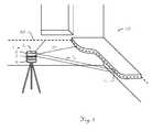
- Fig.1shows a schematic representation of the inventive distance-measuring method for a reference line projecting device 1 with an electro-optical distance meter.
- the device 1generates optical radiation that is emitted through an optically transparent opening or hood 2 as an optical reference beam RS and guided along a defined reference path RP, wherein at least a portion of the reference path RP as it passes through the human eye and / or detectors as a reference line is detectable.
- the emissionis guided by a beam deflection means 3 as means for directing the reference beam RS, which is moved by a drive 4.
- further processing operationscan be related to their positioning, for example by the distance to a reference line projected visually on a surface OF is measured.
- a reference line projected visually on a surface OFis measured.
- a projectionis possible, which is detected by a detector when hitting it.
- the reference linehas more than a single point, so that a course of the reference line is detected.
- a distance measurementis carried out to at least one point P i of the reference path RP, but in particular to many points P i , for example when they are used to scan a portion of the reference path RP.
- the measuring principleis based here on the emission of a measuring beam parallel or coaxial to the reference beam RS or the use of the reference beam RS as a measuring beam and subsequent reception of portions of the reflected measuring beam and deriving a signal from these components.
- the corresponding signalscan be recorded at a measuring rate of 1 kHz or more.
- an angle measurement or angle determination of the deflection direction to the point P itakes place in synchronism with the distance measurement.
- the determination of the distance D i to the at least one point P iis based on the below in Figure 3 and 4 shown modulation and evaluation of the signal, wherein the guiding along the reference path RP can also be repeated.
- a distance D i or a distance-related variablesuch as the signal shape or phase, is determined for each angular position of the receiver for at least one point P i .
- the distance D ican then be determined from the distance-related quantities. This can be done by repeatedly traversing the reference path RP accumulates the portions of the measurement beam received for the at least one point P i and / or aggregates its associated signals.
- the reference path RPdefined and can be variably specified.
- the plane of rotationcan be tilted by changing the position of the axis A, so that correspondingly inclined planes (degrees) can be realized.
- free-form figurescan also be projected as reference lines or scanned for distance measurement.
- the guiding along the reference path RPmay be performed at such a speed that, during the traversal, the reference path RP is simultaneously perceivable to the human eye in its entirety.
- the userthen sees a continuous line projected around the wall.
- the emitted radiationadvantageously has a wavelength in the visible range, but in principle induced fluorescence or similar effects can also be used.
- the measuring beamcan be collimated and have a beam cross-section with a diameter of 5 mm or less.
- the rotation laseris positioned so that the height and orientation of its projected laser plane corresponds to that of a worktop in the corner of a room, so that the reference path RP comes to rest on its edge and the worktop is automatically measured.
- Such, in particular horizontal positioningallows, for example, the measurement of surfaces, as in Fig.2 based on the schematic representation of in Fig.1 shown situation in plan view is clarified.
- the reference beam RSwhich in this example simultaneously represents the measuring beam, scans the space in an angular range of 360 ° in one plane and thus two-dimensionally, whereby a tube and the worktop in the corner are detected and measured.
- the reference paththus lies in a plane generated by the rotation of the reference beam RS around an axis of rotation as an optical measuring beam, wherein the rotation takes place, for example, with a defined angular velocity of at least 4n rad / s.
- the orientation or zero directioncan be set to an external coordinate system.
- fast angle encoderswith accuracy of seconds can be used. If the angular velocity is defined and this is kept sufficiently constant, then the angles ⁇ i can also be determined on the basis of the time assignment, so that a component directly measuring the angle can be dispensed with.
- the area of the space A1, the cross-sectional area A2 of the pipe and the area A3 of the work surfacecan then be determined.
- the contours or borders of the objects to be measuredthen result in part from the measurements along the reference path as well as by calculation or assumptions for the non-scanned or non-scannable area.
- the back, ie the side facing away from the device 1can be estimated from the course of the walls of the room left and right of the worktop.
- a further measurement above or below the worktopcan be carried out so that the wall course located behind it can also be scanned directly. It is advantageous, however, if in the device 1 geometric basic forms are stored as measurement or calculation information that can be selected accordingly.
- the width B door of a door leading to the roomcan be determined automatically.
- Figure 3illustrates a preferred distance measuring principle for a method according to the invention with reference to a schematic representation of a typical signal sequence as it occurs in an electronic distance meter.
- the waveformis plotted against the time axis, with the dots denoting sample and sampling points, respectively.
- the left pulseis here, as in runtime meters, a start and the right pulse a stop pulse.
- the duration and thus the distance D ifor example, from the time interval of the vertices of the two pulses, the pulses are sampled similar to phase meters .
- a corresponding methodis described, for example, in the international PCT application with the registration no. PCT / EP2007 / 006226 explained in his principles.
- the Solutionis based on the combination of two common in distance measurement basic principles for signal detection.
- the first basic principleis based on the measurement signal detection using the threshold value method and the second basic principle on the signal sampling with downstream signal processing for identification and temporal position determination of the signal.
- the threshold value methodalthough the signal detection is usually determined by the signal amplitude exceeding a threshold value, the distance-determining signal characteristic can be quite different.
- the rising edge of the received signalcan trigger the time trigger, but on the other hand, the received signal can be converted by means of an electronic filter in another suitable form to generate a trigger feature, which is advantageously independent of the pulse amplitude.
- the corresponding trigger signalis supplied as a start or stop signal to a timing circuit.
- the core of the principleis a lossless signal acquisition, which is lossless in the sense of preserving the term information to understand.
- the approachis based on the direct signal sampling of the received time signal in the GHz range.
- the pre-amplified by a broadband, but extremely low-noise transimpedance receiver signalis sampled with a fast AD converter and with quantized at least 8 bits.
- Such a transimpedance amplifieris described for example in the European patent application with the application no. 07114572 described.
- This AD converteris characterized by a low INL (integral nonlinearity) and a negligible in the field of measurement accuracy aperture jitter, where aperture jitter means the temporal variation of the scanned points or areas, ie the distance from sample to sample.
- This AD converteris clocked by a highly stable oscillator unit. This is essentially determined by the track-and-hold unit at the input of the AD converter, typical values being 1 to 2 psec.
- INLis the dynamic range of a straight line deviating transfer function of the implemented in the AD converter quantization unit understood.
- An ideal AD converterproportionally converts the amplitude of an analog input signal into a digital code on the output. In the real case, however, the deviation can amount to about 0.3 LSB, which can lead to disturbing signal distortions. This aspect is particularly important to ensure measurement accuracy at high and low amplitudes. Measures to eliminate these influences are known, for example, some AD converters have a so-called Dishlibrierfunktion which measure from time to time the INL and reduce internally accordingly.
- the sampling pointsare distributed equidistantly, the distances are maintained with an accuracy of less than 5 psec.
- the analog bandwidth of the AD converter upstream analog receivermoves in the range of 40 to 400 MHz, which causes the voltage applied to the AD converter Input signal is smoothed over several sampling intervals. It is essential that the AD converter on the one hand does not reduce the signal-to-noise ratio, but on the other hand does not distort or lapse in time the signal propagation time to be measured.
- the stop pulseis directed by the transmitting unit to the target to be measured and passed through a receiving optics on a photodetector.
- the resulting time signalcontains at least one start pulse and a stop pulse corresponding to each optically illuminated target.
- the scanning sequence after the AD converteris fed to an FPGA (field programmable gate array) or a PLD (programmable logic device) and processed there in real time.
- the samplesare buffered in a digital signal vector.
- the length of such a data recorddetermines the maximum distance to be measured. For example, if 8192 samples are buffered at a sampling rate of 1 GS / sec, this record length corresponds to a time axis of 8192 nsec, which in turn equals a maximum distance of 1229 m.
- a second stepfollows a signal analysis, it is the time axis, or the digital signal vector, searched for a start pulse and any Stoppulsen.
- the position of the pulsesis thus accurately known to a sampling interval.
- the differencecorresponds to a first rough estimate of the distance D i to be determined.
- DFTdigital Fourier transformation
- evaluation methodswhich are robust with respect to signal distortion and saturation; in this case approaches from digital filter and estimation theory are often used. With these methods 1 mm measuring accuracies can be achieved.
- a beam source 5for example, a laser diode, with appropriate control LD, wherein a first part of the radiation are passed internally directly to the receiver 6 and a second part of the radiation externally to the target to be measured.
- the radiation reflected at the targetis then also guided via a receiving optics to the receiver.
- the receiver-side signal chainhas a subnanose Medicalschnellen photodetector as a receiver 6, such as an avalanche photodiode, a broadband and low-noise current-to-voltage converter TIA with a matched to the laser pulse cutoff frequency, as described for example in the European patent application with the application no. 07114572 is described, a possible distortion and low noise voltage amplifier LNA and at least one high-speed AD converter ADC.
- the wideband and low-noise current-to-voltage converter TIAcan be used, for example, as a transimpedance amplifier circuit for converting an input current into one Output voltage U out be composed of amplifier element with signal input and output and a T-shaped feedback network. With optimally dimensioned feedback networks linear amplifiers with bandwidths of over 500 MHz and low input noise currents can be realized.
- the T-shaped feedback networkhas a first, a second and a third branch, which are each connected to a node K to one side.
- the first branchon the other hand connected to the output of the amplifier element, has a feedback resistor R 1 .
- This feedback resistor R 1causes a current noise I noise , by I noise .
- R 14 ⁇ kT R 1 where T is the absolute temperature and k is the Boltzmann constant.
- the current flowing through the feedback resistor current I R1is capacitively divided at the node K, so that only a portion of this current - and thus only part of the noise current - is returned to the input of the amplifier element. For example, by means of this current division-considered in relation to the transimpedance of the circuit-a noise-poorer amplifier circuit can be realized.
- the second branch of the T-shaped feedback networkhas at least one capacitive component C 2 and the third branch, which leads to the signal input of the amplifier element, at least one capacitive component C 3 .
- the signal lines between the components of the receiver circuitare preferably differentially guided.
- the receiver-side signal chaincan also be divided into several paths with different amplification. Each of these paths is then fed to a corresponding AD converter.
- Standard AD converterstypically have 2 or more input channels. As a result, the reception signal dynamics can be extended.
- the digital signal sequencesare forwarded to at least one FPGA or a PLD (programming logic device) for signal processing and processing.
- FPGAfield-programmable gate array
- PLDprogramming logic device
- the resources of today's FPGAare sufficient to evaluate the distance evaluation between start and stop pulses in real-time mode at a rate up to 1 MPts / sec and output them on a high-speed interface.
- Fast FPGAsalso allow for the distance evaluation synchronous calculation and output of the signal strength, in particular that of the stop pulse. By parallelizing the calculation processes, energy-saving PLDs can also be used.
- a memory unit MEMis provided for the storage of the data.
- the FPGAIn the case of weak reception signals, it is possible to switch from single shot mode to accumulation mode depending on the situation. In this operating mode, the FPGA sums the digital signal vectors associated with the measurement sequences synchronously in time with the laser shot rate and stores the data in a correspondingly long memory. Time-delayed, but continuously the distance is calculated and output. This method has the advantage that even very weak reception pulses can be measured and the measurement speed remains high.
- a different method for increasing the measuring sensitivitycan also be used on account of the multiple measurement of the same profile.
- distance measurementsare determined according to the single-shot method, but at the same time an accumulation mode is activated, which stores the distances measured and measured according to the scanned profile in an additional memory.
- the memory lengthcorresponds exactly to the number of points on a profile track and depends inter alia on the repetition or rotation frequency.
- the FPGAsums distances that correspond to exactly one associated point on the object profile.
- the length of this profile memorycorresponds to a track across the object to be measured.
- the constantly improving distancecan be continuously updated and output together with the angle measurement. Whereby this method also has the advantage that poorly reflecting rooms and objects can be accurately measured or scanned.
- the basis for the accurate transit time measurementis derived from a temperature-corrected quartz MC. These are commercially available and have a typical accuracy of 0.2 ppm.
- the time or clock signal of the quartzis high-multiplied by means of a PLL oscillator VCO, for example, to 1 GHz low noise.
- the output signal of the oscillator VCOforms the picosecond time signal of the AD converter.
- the latterforwards the time signal or clock to a digital clock manager on a specially provided PIN, this unit can be designed as a state machine in the FPGA.
- this Digital Clock Managerhas the function on the laser trigger line to generate the configured laser shot frequency synchronously to the AD converter with picosecond accuracy.
- the distance measuring circuit together with detector control, temperature sensors and any adjustable optical attenuatorsis controlled by a central control unit CU.
- a marking of target points by cooperative target objectssuch as reflectors
- it is also possible to initiate a scanning sequence from the signal profilewhich is described in US Pat Figure 5 is presented as an application example of the distance measuring principle.
- Figure 7As shown by reflectors measuring points can be made recognizable, since the increased reflectivity compared to the non-cooperative background, a corresponding increase in the signal strength as a function of the measuring point number or the angle in the profile occurs.
- the marking of measuring pointsthus allows the triggering of an automated measuring process, which in Figure 5 is illustrated for the example of recording a surface profile between two reflectors.
- an increase in the signal intensityis detected by the receiver, which leads to the triggering of a continuous distance measuring operation with recording of the corresponding data, that is, from measuring points P i and assigned after exceeding a threshold value SW
- the first increase in intensitythus defines by the first sample, which is above the threshold SW, a starting point SP, which is terminated in the same way by the first threshold exceeding sample of the second intensity increase as the end point EP again.
- start and EndddlingSPEP is thus a Profile window of the recording length A M set.
- thiscan also be manual, angle-controlled, ie with a
- Start angle ⁇ S and an end angle ⁇ Eby specifying a stored measurement process or otherwise triggered.
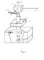
- a first exemplary embodiment of the reference line projecting deviceis disclosed in US Pat Figure 6 shown schematically.
- the devicehas a beam source 5, for example a laser diode, for generating a reference beam RS which simultaneously serves as measuring radiation 7 and is emitted via the beam deflection means 3 moved by a drive 4 about an axis A as means for directing the reference beam RS.
- the deflection angleis 90 degrees, so that the reference beam generates a plane.
- the drive 4is shown here only by way of example via a belt.
- a wide variety of drive components known to the person skilled in the artfor example by means of gears or directly driven hollow shaft motors, can be used.
- a mirroris used as fixed to the axis A beam deflection 3, wherein the axis A of the rotation via a tilting table 10 is vertically aligned, in particular using inclination sensors 11.
- a movable or rotatable beam sourcecan be used, so that a beam deflection 3 can be omitted.
- the means for directing the reference beam RScomprise the movable beam deflection means 3, which generates a level which can be leveled, and this
- two inclination angles ⁇ 1 and ⁇ 2can be tilted, so that the axis A in a defined direction by a defined angle ⁇ N inclined relative to the vertical perpendicular direction can be aligned.
- the pentaprism as beam deflection means 3causes the reference path RP to lie in a plane perpendicular to the axis A and the measurement beam to rotate about the axis A, in particular with a defined angular velocity of at least 4n rad / s.
- the respective positions of the beam deflection means 3, ie the emission angle of the measurement beamcan be derived by means for determining the angles ⁇ i .
- the positioncan be measured directly by means of additional angle sensors 4a belonging to the drive 4 or can be determined at a constant rotational speed by assignment to the emission time point.
- the measuring radiationcan be in the form of emission parallel or coaxial to the reference beam, or else the reference beam RS itself can be used as measuring beam, this being controlled correspondingly by an electronic distance measuring unit.
- the characteristic of the radiation to be emittedis selected so that at least a part of the reference path RA can be detected as a reference line as it passes through the human eye and / or detectors.
- the portions 8 of the measuring or reference beam RS which are reflected by a surfaceare in turn guided via the beam deflection means to a receiver 6 as a photosensitive receiving component, which is part of the electronic distance measuring unit.
- the determination of distances D i to points P i in the reference pathis carried out in an evaluation unit 9, wherein this is designed so that at a corresponding selection of a mode of the reference path contains at least one point, which is measured when passing through the reference path for determining its distance D i .
- the devicecan be set so that the means for directing the reference beam RS are controlled in such a way that a repeated, in particular repeated, traversing of the reference path takes place automatically, whereby a continuous data acquisition for distance determination takes place.
- the evaluation unit 9 or a programmay comprise, whereby the signal 8 of the measuring beam measured during the repeated passage of the reference path for the at least one point P i is accumulated and / or associated signals are aggregated.
- Preferably digitized signal valuesare fed to filter banks, which continuously average the measured values and thus lead to improved coordinates.
- filter bankswhich continuously average the measured values and thus lead to improved coordinates.
- IIR filtersare suitable, with which noise suppression by frequency filtering can be realized on-line.
- the distance measuring unitshould have a sampling rate of at least 1kHz, so that the profile points are sufficiently tight on the reference path
- the devicethus has a transmission beam path 7 between the laser source and the means for directing the reference beam RS and a receiving beam 8 between the means for directing the reference beam RS and the receiver 6, wherein the transmission beam path 7 and the receiving beam path 8 coaxial or parallel are arranged to the axis A.
- a Part of emitted by the beam source 5 measuring beams deviceinternally be directed to the receiver 6.
- Figure 7explains a first application example of the inventive method with a cooperative target schematically.
- a reference line projecting device 1is positioned in a room, whereby by means of reference path RP, a plane serving as a height reference plane is projected onto the walls.
- a plurality of measuring points MP 1 -MP 3can be distinguished by positioning a marking unit 12.
- the device 1recognizes a reflective element 12a attached to the marking unit 12, which serves to identify a point P i of the reference path RP.
- the device 1now combines with the reflections of the reflecting elements 12a connected positions with the measuring points MP 1 -MP 3 , which allows, for example, the definition of structural features in space or the triggering of operations, such as a scan or the measurement of a lateral distance.
- a measuring system of reference line projecting device 1 and marking unit 12distances on surfaces can thus also be defined and measured.
- sub-profiles defined by marking unitscan be included between measuring points MP k .
- the reference line projecting device 1 and the marking unit 12have communication means for producing an at least one-sided, in particular mutual communication connection so that data can be transmitted or also the device 1 can be remotely controlled via the marking unit 12.
- each point in spacecan be determined appropriately and its coordinates (x, y, z).
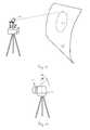
- Figure 8shows the schematic representation of a second application example of the inventive method with a cooperative goal.
- a marking unit 13is used, which is able to determine its own height H M , which can be done either by its own distance measuring functionality to the ground or a mechanical distance determination.
- the marking unit 13may also have a plumb bob 13b and a dragonfly as the inclinometer 13c.
- the marking unit 13can then be positioned on the ground with the tip of the pole 13b and placed in a vertical position by means of the inclinometer 13c, so that the height is defined by the position of the reflecting element 13a, together with the zero-height mark 13d on the pole 13b ,
- the reflective element 13acan preferably also be displaceable relative to the pole 13b, wherein the exact height can be read on the basis of a graduation.
- the measurement of depressions in flat roofscan be carried out with such a surveying system.
- the device 1 designed, for example, as a rotary laseris placed on the roof, the plane of the reference beams being leveled in this case.
- the marking unit 13is now the flat roof at different locations, especially in the area of recesses or water accumulations with the lower end of the Lotstocks 13b contacted.
- the pole 13bis aligned vertically and the reflecting element 13a with the zero-height mark 13d is displaced until it is detected by the measuring radiation of the device 1.
- the reflective element 13amay also be formed with a detector functionality for the measurement or reference beam, so that the marking unit 13 recognizes automatically when the reflective element 13a enters the plane of the reference beam RS, which means that a corresponding height H M can be read.
- the device 1In this group of application examples also includes the measurement of squares or terrain slopes with a uniform slope. In these tasks, the device 1 generates a reference beam of rays which defines a correspondingly inclined plane.
- a second embodiment of the inventive deviceis in Figure 9 shown schematically.
- the structureis similar to the one in Figure 6 illustrated device.
- the beam deflection means 3 'designed as a mirror surfaceare now tiltable about a horizontal axis, so that a rapid adjustment of the
- Emission directioncan be done in two angles ⁇ and ⁇ .
- galvano mirrorscan be used as quickly pivotable deflecting means.
- the two axes of rotationare perpendicular to each other.
- the projection of reference lineswith basically any course can be realized.
- pivotable mirror surfacescan also find other known to those skilled optical components as means for guiding the reference beam use as Strahlumlenkstoff.
- deformable mirror surfaceseg as a micromechanically adjustable component, also permit beam guidance in two axes.
- Figure 10illustrates an application example of the second embodiment of the inventive device.
- This deviceis now capable of producing a surface or at least reference-path topography due to surface scanning and measurement to points in the reference path.
- Thisallows a projection of the reference radiation RS in a manner which compensates for projection distortion by the shape of the surface OF, ie the projection of the reference path is distorted in a manner which in turn results in the intended undistorted image on the curved surface.
- Figure 10This is shown for the example of a circular cutout, which is to be introduced into an inclined or additionally curved surface. Due to the inclination and curvature, a reference line appearing circular on a flat and vertical wall would be distorted into an ellipse.
- the contours of boreholes or outbreaks for channel penetrationscan be staked.
- fig.11illustrates a third embodiment of the inventive device 1 '.
- the structureis again similar to that in Figure 6 illustrated device.
- the rotary laser equipped deviceis mounted laterally on a turntable 14.
- turntable axis and axis of rotation Aare perpendicular to each other.
- the plane of the reference beamsis thus parallel to the turntable axis.
- the 3D coordinates of the whole roomcan be measured.
- the embodimentthus has a functionality comparable to a scanner.
Landscapes
- Physics & Mathematics (AREA)
- Engineering & Computer Science (AREA)
- General Physics & Mathematics (AREA)
- Radar, Positioning & Navigation (AREA)
- Remote Sensing (AREA)
- Electromagnetism (AREA)
- Computer Networks & Wireless Communication (AREA)
- Optical Radar Systems And Details Thereof (AREA)
- Length Measuring Devices By Optical Means (AREA)
- Measurement Of Optical Distance (AREA)
Abstract
Description
Translated fromGermanDie Erfindung betrifft ein distanzmessendes Verfahren für ein referenzlinienprojizierendes Gerät mit einem elektro-optischen Distanzmessers nach Anspruch 1 und ein distanzmessendes Gerät nach dem Oberbegriff von Anspruch 13 sowie ein Vermessungssystem.The invention relates to a distanzmessendes method for a reference line projecting device with an electro-optical distance meter according to
In vielen Anwendungen werden sichtbare oder unsichtbare Referenzlinien projiziert, die entweder für das menschliche Auge oder für elektronische Systeme als Referenz dienen, welche auch eine automatische Positionierung oder Maschinenführung erlaubt. Hierbei erfolgt die Erzeugung der Referenzlinien zumeist durch Aufweitung eines Laserstrahls, was insbesondere für gerade Linien möglich ist, oder aber durch Projektion eines Laserpunktes, der entlang einer Trajektorie bewegt wird, was grundsätzlich beliebige Pfade und damit Referenzlinien erlaubt.In many applications, visible or invisible reference lines are projected which serve as a reference for either the human eye or electronic systems, which also allows for automatic positioning or machine guidance. In this case, the generation of the reference lines usually takes place by widening a laser beam, which is possible in particular for straight lines, or by projection of a laser point which is moved along a trajectory, which basically allows arbitrary paths and thus reference lines.
Ein Beispiel hierfür sind Rotationslaser, die zur Festlegung einer Ebene mit sichtbarem oder unsichtbarem Laserstrahl dienen und seit vielen Jahren in Verwendung sind, beispielsweise im Bau- oder im Industriegewerbe. Sie sind ein wertvolles Hilfsmittel um Konstruktionslinien entlang horizontaler, vertikaler aber auch definiert schiefen Ebenen zu markieren. Bisherige Rotationslaser haben aber den Nachteil, nur die eine Dimension wie Höhe oder Schiefe zu definieren, was die Effizienz beim Benutzer reduziert.An example of this is rotary lasers, which are used to define a plane with visible or invisible laser beam and have been in use for many years, for example in construction or in the industrial sector. They are a valuable tool to mark construction lines along horizontal, vertical or defined oblique planes. However, previous rotary lasers have the disadvantage of defining only one dimension, such as height or skewness, which reduces user efficiency.
Andere Systeme sind beispielsweise Laser-Nivelliere mit Nadir- oder Zenit-Strahl, die zur Definition von Lotlinien für Wände, Steigleitungen, Kabelkanäle, Klimaschächte, horizontale Fenstersims, Einbauplatten, Rohre oder Leitungen geeignet sind. Diese Referenzlinien können dabei mit dem Auge oder einem optischen Detektor erfassbar sein, wobei zumeist eine für das Auge sichtbare Markierung erzeugt wird.Other systems include nadir or zenith beam laser levels, which are suitable for defining solder lines for walls, risers, cable ducts, air conditioning ducts, horizontal window sills, mounting plates, pipes or conduits. These reference lines can do this be detectable with the eye or an optical detector, wherein usually a visible to the eye mark is generated.
Ein Laserlevel projiziert dabei lediglich eine Linie auf dem bestrahlten Objekt, in der Regel in Verbindung mit einer definierten, dem Nutzer sichtbar vorzugebenden Höhe. Die hier verwendete Information ist somit ebenfalls nur eindimensional. Oft sollen jedoch darüber hinaus noch weitere Informationen ermittelt oder visualisiert werden, z.B. besteht bei gewissen Aufgaben der Bedarf, neben der Höhe auch den Abstand (x) oder die laterale Position (x,y) von einem Punkt zu messen, zu überprüfen oder sichtbar vorgegeben zu erhalten, so zum Beispiel bei einer Flachdachsanierung, wo die Senkungen nicht nur in der Höhe sondern auch in der lateralen Position bekannt sein müssen.A laser level projected thereby only a line on the irradiated object, usually in conjunction with a defined, the user visibly specified height. The information used here is thus also only one-dimensional. Often, however, further information is to be determined or visualized, e.g. For certain tasks, there is a need to measure the distance (x) or the lateral position (x, y) from a point in addition to the height, check or visibly given, such as in a flat roof renovation, where the subsidence not only in height but also in the lateral position must be known.
Zudem stehen bisherigen Systemen zur Projektion von Referenzlinien keine Informationen über die Oberfläche, auf die eine Projektion erfolgt, zur Verfügung. Ohne Kenntnis von Form und Lage der Oberfläche zum System kann eine Projektion zu Verzerrung der projizierten Referenzlinien führen.In addition, prior projection line systems have not provided information about the surface to which projection is being made. Without knowing the shape and location of the surface to the system, projection may result in distortion of the projected reference lines.
Auch erlaubt die fehlende Kenntnis der Oberfläche keinerlei an diese angepasste Markierung. Soll beispielsweise in einem definierten Abstand links und rechts einer Türöffnung Bohrungen angebracht werden, so muss bisher eine separate Messung manuell durchgeführt werden, durch die der seitliche Abstand bestimmt wird. Eine projizierte Referenzlinie dient nur zur Angabe der Höhe dieser Bohrungen. Insbesondere können Systeme des Stands der Technik eine solche Struktur nicht automatisch identifizieren.Also, the lack of knowledge of the surface does not allow any mark adapted to this. If, for example, bores are to be provided at a defined distance to the left and right of a door opening, a separate measurement must hitherto be carried out manually by which the lateral distance is determined. A projected reference line is only used to indicate the height of these holes. In particular, prior art systems can not automatically identify such a structure.
Aus dem Stand der Technik allgemein bekannte Systeme zur Erfassung von Abmessungen sind Laserscanner, die Oberflächen Punkt für Punkt entlang eines Messpfades abtasten und vermessen. Allerdings stellen sie keine Funktionalitäten bereit, die eine Referenzlinie vorgeben oder eine sichtbare Marke projizieren können, welche wiederum dem Nutzer eine Interaktion ermöglichen würden. Damit fehlt jegliche Verknüpfung von Oberflächenerfassung und Ausgabe von erfass- oder wahrnehmbaren Hinweisen oder Markierungen. Zudem weisen Scanner aufgrund ihres Anwendungszwecks nur eine relative Präzision der Messungen zueinander auf, eine hochpräzise Vorgabe einer Richtung (Orientierung) zu einem äusseren oder globalen Koordinatensystem ist demgemäss weder erforderlich noch geräteseitig realisiert, so dass vertikale Ablotungen mit solchen Vorrichtungen zu ungenau sind. Auch ist eine präzise Höhenmessung, welche den Anforderungen oder Spezifikationen im Bauwesen genügt, nicht möglich.State-of-the-art dimensional sensing systems are laser scanners that scan and measure surfaces point-by-point along a measurement path. However, they do not provide functionalities that can dictate a reference line or project a visible mark, which in turn would allow the user to interact. Thus, there is no linkage between surface detection and output of detectable or perceptible indications or markings. In addition, because of their intended use, scanners have only a relative precision of the measurements relative to one another; a high-precision presetting of a direction (orientation) to an external or global coordinate system is accordingly neither required nor implemented on the device side, so that vertical surveys with such devices are too inaccurate. Also, a precise height measurement, which meets the requirements or specifications in the construction industry, not possible.
Eine Kombination von Entfernungsmess- und Projektionsfunktionalität ist aus der
Ultraschall-Distanzmesser weisen zudem Genauigkeiten im cm-Bereich auf und sind daher für die meisten Bauanforderungen zu ungenau. Besonders nachteilig ist die durch Beugung aufgefächerte Schallwelle, welche am Zielobjekt eine mehrere cm grosse Ausdehnung annimmt. Kanten von Trägern oder Türrahmen können damit nicht vermessen werden.Ultrasonic distance meters also have accuracies in the cm range and are therefore too imprecise for most building requirements. Particularly disadvantageous is the diffracted by diffraction sound wave, which takes on the target object a several cm large extent. Edges of beams or door frames can not be measured.
Die
Ein System mit einer rundumlaufender Entfernungsmessung für eine mobile Arbeitsmaschine wird in der int. PCT-Anmeldung mit der Anmelde-Nr.
Der Erfindung liegt somit die Aufgabe zugrunde, ein verbessertes referenzlinienprojizierendes Gerät bzw. ein entsprechendes Verfahren bereitzustellen.The invention is therefore based on the object to provide an improved reference line projecting device or a corresponding method.
Eine weitere Aufgabe besteht in der Bereitstellung eines solchen Verfahrens oder Gerätes, das Informationen über die Oberfläche, auf welche die Projektion erfolgt, ermittelt, insbesondere um die Projektion entsprechend anzupassen.Another object is to provide such a method or apparatus that determines information about the surface to which the projection is made, in particular to adjust the projection accordingly.
Eine weitere Aufgabe besteht in der Bereitstellung eines referenzlinienprojizierenden Verfahrens oder Gerätes, das bearbeitungsleitende Markierungen und/oder Informationen ermittelt, bereitstellt bzw. projiziert.A further object is the provision of a method or device which projects reference lines and which determines, prepares or projects processing-relevant markings and / or information.
Eine weitere Aufgabe besteht in der Bereitstellung eines referenzlinienprojizierenden Verfahrens oder Gerätes, das Linienprofile von Oberflächen ermittelt.Another object is to provide a reference line projecting method or device that determines line profiles of surfaces.
Eine weitere Aufgabe besteht in der Bereitstellung eines referenzlinienprojizierenden Verfahrens oder Gerätes, das mit einer Schar von Linienprofilen die 3D-Koordinaten von Oberflächenpunkten bestimmt und die Profile oder Koordinaten ausgibt.Another object is to provide a reference line projecting method or apparatus that Using a set of line profiles to determine the 3D coordinates of surface points and output the profiles or coordinates.
Diese Aufgaben werden durch die Verwirklichung der kennzeichnenden Merkmale der unabhängigen oder abhängigen Ansprüche gelöst.These objects are achieved by the realization of the characterizing features of the independent or dependent claims.
Bei einem erfindungsgemässen distanzmessenden Verfahren bzw. einem ebensolchen Gerät werden referenzlinienprojizierende und distanzmessende Funktionalität integriert, indem die zur Projektion genutzte Emission oder zumindest deren Strahlgang ebenfalls für eine Entfernungsmessung genutzt wird. Hierbei wird anhand eines optischen Messstrahls, der durch einen elektronischen Distanzmesser emittiert wird, ein definierter Messpfad durchlaufen bzw. abgefahren, d.h. der Messstrahl wird derart geführt, dass die Trajektorie seiner Projektion diesem definierten Messpfad und der zu projizierenden Referenzlinie entspricht. Dabei wird zu mindestens einem Punkt des Messpfades, insbesondere zu einer Vielzahl von Punkten des Messpfades, eine Distanz bestimmt, wobei erfindungsgemäss innerhalb eines Messvorgangs, d.h. für das Bestimmen der Distanz, der Messpfad mindestens einmal wiederholt, insbesondere vielfach wiederholt, durch die Projektion des Messstrahls abgefahren bzw. durchlaufen wird. Im Gegensatz zu abtastend bewegten Systemen wird somit der gleiche Pfad mehrfach durchlaufen und somit bei winkelsynchronen Distanzmessungen die Profilpunkte mehrfach abtastet. Geräteseitig erfolgt erfindungsgemäss eine Integration eines hochempfindlichen Distanzmessers in die projizierende Einheit, wobei vorzugsweise die Strahlgänge von Messstrahl und Projektionsstrahl koaxial gekoppelt sind.In a distance-measuring method or device according to the invention, reference line projecting and distance-measuring functionality is integrated in that the emission used for the projection or at least its beam path is likewise used for a distance measurement. In this case, a defined measuring path is traversed or traversed on the basis of an optical measuring beam which is emitted by an electronic distance meter, ie the measuring beam is guided such that the trajectory of its projection corresponds to this defined measuring path and to the reference line to be projected. In this case, a distance is determined for at least one point of the measuring path, in particular for a plurality of points of the measuring path, wherein according to the invention within a measuring operation, ie for determining the distance, the measuring path is repeated at least once, in particular repeatedly repeated, by the projection of the measuring beam is traversed or run through. In contrast to scanning systems moving the same path is thus repeatedly traversed and thus repeatedly scans the profile points in angle-synchronous distance measurements. On the device side, according to the invention, an integration of a highly sensitive distance meter into the projecting unit takes place, the beam paths of the measuring beam and the projection beam preferably being coaxially coupled.
Durch das wiederholte Abfahren des definierten Messpfades mit der Projektion des Messstrahls können bei jedem Durchlauf Distanzgrössen jeweils für Punkte des Messpfades ermittelt und für die Bestimmung der Distanzen zu den Punkten diese Distanzgrössen jeweils akkumuliert, d.h. gesammelt, und insbesondere gemittelt werden. Grundlage hierfür ist das mehrfache winkelsynchrone Durchlaufen ein- und desselben Messpfades, der damit einen wiederholten Empfang von Messstrahlung eines Messpunktes und damit deren Akkumulation erlaubt. Diese Akkumulation kann dabei sehr strahlungsnah, d.h. beispielsweise als Ladungsträgerakkumulation in einem photosensitiven Element, oder auf der Ebene der Signalverarbeitung, z.B. durch Speichern und Aufaddieren digitalisierter Werte, erfolgen. Hierbei können Distanzmesswerte grundsätzlich entweder bei jedem Durchlauf bestimmt und laufend ausgegeben oder nachfolgend weiterverarbeitet, z.B. gemittelt werden, oder aber die Distanzbestimmung erfolgt erst nach einer Mehrzahl von Durchläufen, z.B. anhand der bis dahin für jeden Messpunkt akkumulierten Ladungsträger oder aggregiertem Signal. Für den Fall einer laufenden Distanzausgabe eignen sich sogenannte IIR-Filter (infinite impulse response), diese digitalen Filter sind besonders für schnelle Verarbeitung und Verbesserung von Messfolgen geeignet.By repeatedly traversing the defined measuring path with the projection of the measuring beam, distance quantities can be determined for each pass for points of the measuring path and for the determination of the distances to the points these distance variables are respectively accumulated, i. collected, and in particular averaged. The basis for this is the multiple angle-synchronous passage through one and the same measuring path, which thus allows a repeated reception of measuring radiation of a measuring point and thus its accumulation. This accumulation can be very close to the radiation, i. for example as charge carrier accumulation in a photosensitive element, or at the signal processing level, e.g. by storing and adding digitized values. In this case, distance measurement values can basically either be determined on each pass and output continuously or subsequently processed further, e.g. are averaged, or the distance determination takes place only after a plurality of passes, e.g. on the basis of the charge carrier or aggregated signal accumulated until then for each measurement point. In the case of a current distance output so-called IIR filters (infinite impulse response) are suitable, these digital filters are particularly suitable for fast processing and improvement of measurement sequences.
Die Messrate und damit die Auslegung der entfernungsmessenden Einheit sind hierbei abhängig von der Winkelgeschwindigkeit beim Durchlaufen der Trajektorie, wobei diese wiederum von der Erfassbarkeit durch das menschliche Auge oder einen elektronischen Detektor vorgegeben wird. Die mit solchen Bedingungen verbundenen typischen Messraten liegen dabei im Bereich von 1kHz bis einige 1000kHz. Weitere zu realisierende Eigenschaften des Systems sind eine radiale Messgenauigkeit von unter 3 mm, eine laterale Auflösung entlang des Messpfades von weniger als 5 mm auf 20 m und eine Einsatzentfernung von mindestens bis zu 50 m.The measuring rate and thus the design of the distance-measuring unit are dependent on the angular velocity when traversing the trajectory, which in turn is dictated by the detectability by the human eye or an electronic detector. The typical measurement rates associated with such conditions are in the range of 1 kHz to several 1000 kHz. Further properties of the system to be realized are a radial measuring accuracy of less than 3 mm, a lateral resolution along the measurement path of less than 5 mm to 20 m and a deployment distance of at least 50 m.
Laufzeitmesser des Stands der Technik sind zwar einkanalig und damit koaxial ausführbar, gängige Realisierungen mit mm-Genauigkeit haben aber durchwegs langsame Messgeschwindigkeit im Hz-Bereich, da die Genauigkeit erst durch Mittelung über eine grosse Zahl von Laserschüssen erreicht wird.Time-of-flight meters of the prior art are indeed single-channel and thus coaxial executable, common implementations with mm accuracy but have consistently slow measuring speed in the Hz range, since the accuracy is achieved only by averaging over a large number of laser shots.
Bekannt sind auch schnelle Phasenmesser bis zu einigen 100MPts/sec, jedoch sind solche Vorrichtungen anfällig auf Kanalübersprechen, insbesondere bei koaxial angeordneten Strahlführungen. Bei biaxialen oder morphologisch getrennten Messstrahlführungen kann ein solcher Distanzmesser grundsätzlich eingesetzt werden.Also known are fast phase meters up to several 100MPts / sec, but such devices are prone to channel crosstalk, especially with coaxially arranged beamlines. In the case of biaxial or morphologically separated measuring beam guides, such a distance meter can basically be used.
Ein für den erfindungsgemässen integrierten Ansatz geeigneter Distanzmesser wird im folgenden dargestellt. Er benutzt dabei einen Sende- und einen Empfangstrahl in koaxialer Anordnung. Dabei unterscheidet sich das Messprinzip sowohl vom klassischen Laufzeitmesser als auch vom Phasenmesser. Zwar wird die Distanz wie bei einem Laufzeitmesser von einer Messung der Laufzeit abgeleitet, hingegen gleichen die radiometrischen Grössen wie Laserleistung und Modulationsfrequenz eher denjenigen eines Phasenmessers. Ein solcher Distanzmesser ist in der Lage mit einer Rate von einigen kHz bis zu wenigen MHz, insbesondere bis zu etwa einem MHz, die Distanz mm-genau zu vermessen, ohne die Grenzwerte der Laserklasse 3R zu überschreiten.A suitable for the inventive integrated approach distance meter is shown below. He uses a transmitting and a receiving beam in a coaxial arrangement. The measuring principle differs from both the classic runtime meter and the phase meter. Although the distance is derived from a measurement of the transit time, as in the case of a transit time meter, the radiometric quantities such as laser power and modulation frequency are more similar to those of a phase meter. Such a distance meter is able to measure the distance mm-exact at a rate of a few kHz to a few MHz, in particular up to about one MHz, without exceeding the limit values of the laser class 3R.
Die Integration eines solch hochempfindlichen Distanzmessers kann mit einem Winkelsensor kombiniert werden. Damit können lokale Koordinaten in einer Ebene oder auf einem Kegel bestimmt werden. Der Winkelsensor oder Drehgeber erfasst dabei den Rotationswinkel des projizierten Referenzstrahls. Mit den Daten des Winkelgebers und des Distanzmessers lassen sich mit hoher Präzision beispielsweise die Koordinaten von markierten, identifizierbaren Strukturen wie zum Beispiel Türweite oder Fensterbreite, oder auch von reflektierenden Objektmarken bestimmen.The integration of such a highly sensitive distance meter can be combined with an angle sensor become. This can be used to determine local coordinates in a plane or on a cone. The angle sensor or rotary encoder detects the angle of rotation of the projected reference beam. With the data of the angle encoder and the distance meter, for example, the coordinates of marked, identifiable structures such as, for example, door width or window width, or also of reflecting object marks can be determined with high precision.
Ist die entfernungsmessende Einheit in einem Grade-Laser, das heisst ein Rotationslaser mit zur Lotrichtung einstellbarer Neigungsebene, eingebaut, so können die lokalen Koordinaten (x,y,z) erfasst werden, dies zumindest in einem begrenztem Grade- oder Neigungsbereich.If the distance-measuring unit is installed in a grade laser, that is to say a rotary laser with an inclination plane which can be adjusted to the perpendicular direction, then the local coordinates (x, y, z) can be detected, at least to a limited degree or inclination range.
Neben den Applikationen in horizontaler oder definiert schiefer Lage kann das erfindungsgemässe System auch in einer sogenannten Lay-down Variante realisiert sein. In dieser Ausführungsform liegt das referenzlinienprojizierende Gerät auf der Seite und ist auf einem Drehtisch plaziert, damit das Gerät um eine, mit einem weiteren Winkelsensor versehene, Stehachse rotieren kann. Die Rotation um die Stehachse wird vorzugsweise in Schritten oder Intervallen ausgeführt, was den Vorteil einer mehrmaligen Aufnahme des jeweiligen Oberflächenprofils und somit einer Aggregation der Punktkoordinaten hat. Durch das schrittweise Verdrehen um die Stehachse kann der gesamte Raum abgetastet werden. Diese Ausführungsform hat also die Funktion eines Punktwolken erzeugenden Scanners aber im Vergleich zu den herkömmlichen Lösungen mit niedriger Komplexität.In addition to the applications in a horizontal or defined slated position, the inventive system can also be implemented in a so-called lay-down variant. In this embodiment, the reference line projecting device lies on the side and is placed on a turntable so that the device can rotate about a standing axis provided with another angle sensor. The rotation about the standing axis is preferably carried out in steps or intervals, which has the advantage of a multiple recording of the respective surface profile and thus an aggregation of the point coordinates. By stepwise turning around the vertical axis, the entire space can be scanned. Thus, this embodiment has the function of a point cloud generating scanner but compared to the conventional solutions with low complexity.
Die Integration eines solchen Distanzmessers in ein referenzlinienprojizierendes mit Winkelgeber ausgerüsteten System erlaubt nun auch die Steuerung der Projektion anhand der ermittelten Informationen, wie z.B. der Oberflächentopographie. Durch die bekannten Objektdaten in einer Drehebene können zum Beispiel Positionen von Bohrlöchern visuell angezeigt werden, sowie durch Verwendung in einem Gerade-Laser auch Positionen von Absteckpunkten unter und über der horizontalen Referenzlinie markiert werden. Um Punkte oder begrenzte Linienbereiche erkennbar zu machen, wird der Projektionsstrahl lediglich in den vorgesehenen, abzusteckenden Bereichen eingeschaltet.The integration of such a distance meter into a reference line projecting system equipped with an angle encoder now also makes it possible to control the projection on the basis of the ascertained information, such as, for example, the surface topography. By means of the known object data in a plane of rotation, for example, positions of drill holes can be visually displayed, as well as positions of stakeout points under and above the horizontal reference line can be marked by use in a straight line laser. In order to make points or limited line areas recognizable, the projection beam is switched on only in the intended, staked out areas.
Insbesondere im Fall eines referenzlinienprojizierenden Systems mit Scannerfunktionalität, d.h. der Fähigkeit zum abtastenden Vermessen zusammenhängender zweidimensionaler Abschnitte, kann die Trajektorie nach einer Bestimmung des Oberflächenprofils an eine gekrümmte Oberfläche so angepasst werden, dass deren Form der unverzerrten Kontur des abzusteckenden Körpers oder Objekts entspricht. Zudem können nach der Identifikation von Strukturen auch auf diese bezogenen Informationen bereitgestellt oder projiziert werden. Beispielsweise kann nach der abtastenden Vermessung entlang des Messpfades ein Fenster identifiziert werden. Nachdem das System über diese automatisch ermittelten Informationen über die Position, Form und Lage des Fensters verfügt, können z.B. Markierungen in einem bestimmten Abstand von der Fensteröffnung automatisch projiziert werden.In particular, in the case of a reference line projecting system with scanner functionality, i. the ability to scan contiguous two-dimensional sections, the trajectory can be adapted to a curved surface after a determination of the surface profile so that its shape corresponds to the undistorted contour of the staked body or object. In addition, after the identification of structures, information relating to these can also be provided or projected. For example, a window can be identified after the scanning measurement along the measurement path. After the system has this automatically determined information about the position, shape and position of the window, e.g. Markers are automatically projected at a certain distance from the window opening.
In ähnlicher Weise kann ein erfindungemässes Gerät bzw. Verfahren auch zur Bauabnahme oder zur Verifikation von Sollgrössen genutzt werden, indem selbsttätig Profile von Oberflächen aufgenommen und mit vorhandenen Sollprofilen verglichen werden. Beispielsweise können so Grundrisse von Räumen durch Vermessen von Wänden oder Raumhöhen durch Aufnahme von Seitenprofilen überprüft werden.In a similar manner, a device or method according to the invention can also be used for building acceptance or for verification of nominal values by automatically generating profiles of Surfaces recorded and compared with existing nominal profiles. For example, floor plans of rooms can be checked by measuring walls or room heights by recording side profiles.
Zudem sind Ausführungsformen des Gerätes realisierbar, die auch in der Lage sind die 3D-Position des Laserlichtflecks am Objekt oder die Koordinaten eines reflektierenden Zielmarkierobjektes zu vermessen. Dies erfordert entweder eine präzise Erfassung der beiden Emissionswinkel, Azimut und Elevation oder aber eine direkte Messung der Lage des Messpunktes, was beispielsweise durch Verwendung eines kooperativen Zielobjekts mit eigener Messfunktionalität bewirkt werden kann. Handelt es sich beispielsweise beim reflektierenden Zielmarkierobjekt um einen sogenannten "Smart Receiver", also einen intelligenten Empfänger oder Reflektor mit eigener Entfernungsmessfunktion oder aber zumindest der Befähigung der Bestimmung der eigenen Höhenposition, so kann auch die Höhenlage des Reflektors als Messpunkt in die Koordinatenvermessung einbezogen werden.In addition, embodiments of the device can be realized, which are also able to measure the 3D position of the laser light spot on the object or the coordinates of a reflective target marking object. This requires either a precise detection of the two emission angles, azimuth and elevation or else a direct measurement of the position of the measurement point, which can be effected, for example, by using a cooperative target object with its own measurement functionality. If, for example, the reflective target marking object is a so-called "smart receiver", ie an intelligent receiver or reflector with its own distance measuring function or at least the ability to determine its own height position, the altitude of the reflector can also be included as a measuring point in the coordinate measurement.
Optional kann auch eine Koordinate eines beliebigen Punktes in der Verlängerung der Achse der intelligenten Zielmarkiereinheit bestimmt werden. Diese Bestimmung erfolgt vorzugsweise berührungslos, z.B. durch einen Triangulationssensor oder eine eigenen Laufzeit- oder Phasenmesser oder aber auch mechanisch, beispielsweise durch einen ausziehbaren Taster.Optionally, also a coordinate of any point in the extension of the axis of the intelligent target marking unit can be determined. This determination is preferably made without contact, e.g. by a triangulation sensor or its own runtime or phase meter or else mechanically, for example by an extendable button.
Aus der Vermessung der Oberflächentopographie können schliesslich auch Flächen- oder Volumenbestimmungen vorgenommen werden, wobei gegebenenfalls auch weitere Informationen über die vermessenen Objekte einbezogen werden. So kann aus dem Profil eines Rohres auf dessen Querschnitt oder bei Kenntnis der Länge auch auf dessen Volumen geschlossen werden. Ein anderes Beispiel ist die Erfassung und Vermessung der Wände eines Raumes. Aus deren Geometrie kann automatisch die Fläche des Raumes bestimmt und damit beispielsweise der Bedarf an Bodenbelag berechnet werden.From the survey of the surface topography surface or volume determinations can finally be carried out, possibly including further information about the measured objects become. So can be closed from the profile of a pipe on the cross section or in the knowledge of the length on the volume. Another example is the acquisition and measurement of the walls of a room. From their geometry, the area of the room can be determined automatically and thus, for example, the demand for flooring can be calculated.
Das erfindungsgemässe Verfahren und das erfindungsgemässe Gerät werden nachfolgend anhand von in den Zeichnungen schematisch dargestellten konkreten Ausführungsbeispielen rein beispielhaft näher beschrieben. Im Einzelnen zeigen:
- Fig. 1
- eine schematische Darstellung des erfindungsgemässen Verfahrens;
- Fig. 2
- die schematische Darstellung der
Fig.1 in Draufsicht; - Fig. 3
- eine schematische Darstellung des Entfernungsmessprinzips für ein erfindungsgemässes Verfahrens;
- Fig. 4
- ein schematisches Blockschaltbild zur Durchführung des Entfernungsmessprinzips;
- Fig. 5
- eine Darstellung des Signalverlaufs für ein Anwendungsbeispiel des Entfernungsmessprinzips;
- Fig. 6
- eine schematische Darstellung eines ersten Ausführungsbeispiels des erfindungsgemässen Gerätes;
- Fig. 7
- die schematische Darstellung eines ersten Anwendungsbeispiels des erfindungsgemässen Verfahrens mit einem kooperativen Ziel;
- Fig. 8
- die schematische Darstellung eines zweiten Anwendungsbeispiels des erfindungsgemässen Verfahrens mit einem kooperativen Ziel;
- Fig. 9
- eine schematische Darstellung eines zweiten Ausführungsbeispiels des erfindungsgemässen Gerätes;
- Fig. 10
- die schematische Darstellung eines Anwendungsbeispiels für das zweite Ausführungsbeispiel des erfindungsgemässen Gerätes und
- Fig. 11
- eine schematische Darstellung eines dritten Ausführungsbeispiels des erfindungsgemässen Gerätes mit natürlich reflektierenden Zielobjekten.
- Fig. 1
- a schematic representation of the inventive method;
- Fig. 2
- the schematic representation of
Fig.1 in plan view; - Fig. 3
- a schematic representation of the distance measuring principle for a method according to the invention;
- Fig. 4
- a schematic block diagram for carrying out the distance measuring principle;
- Fig. 5
- a representation of the waveform for an application example of the distance measuring principle;
- Fig. 6
- a schematic representation of a first embodiment of the inventive device;
- Fig. 7
- the schematic representation of a first application example of the inventive method with a cooperative goal;
- Fig. 8
- the schematic representation of a second application example of the inventive method with a cooperative goal;
- Fig. 9
- a schematic representation of a second embodiment of the inventive device;
- Fig. 10
- the schematic representation of an application example of the second embodiment of the inventive device and
- Fig. 11
- a schematic representation of a third embodiment of the inventive device with naturally reflective targets.
Auf die durch den Referenzstrahl RS erzeugte Referenzlinie können dann weitere Bearbeitungsvorgänge hinsichtlich ihrer Positionierung bezogen werden, z.B. indem der Abstand zu einer sichtbar auf eine Oberfläche OF projizierten Referenzlinie gemessen wird. Neben der sichtbaren oder durch einen Detektor erfassbaren Projektion auf eine Oberfläche ist aber auch eine Projektion möglich, die von einem Detektor beim Auftreffen auf diesen erfasst wird. In beiden Fällen weist die Referenzlinie mehr als nur einen einzigen Punkt auf, so dass ein Verlauf der Referenzlinie erfassbar wird.On the reference line generated by the reference beam RS then further processing operations can be related to their positioning, for example by the distance to a reference line projected visually on a surface OF is measured. In addition to the visible or detectable by a detector projection on a surface but also a projection is possible, which is detected by a detector when hitting it. In both cases, the reference line has more than a single point, so that a course of the reference line is detected.
Erfindungsgemäss erfolgt eine Entfernungsmessung zu mindestens einem Punkt Pi des Referenzpfades RP, insbesondere aber zu vielen Punkten Pi, z.B. wenn diese zur Abtastung eines Abschnitts des Referenzpfades RP dienen. Das Messprinzip basiert hierbei auf dem Aussenden eines zum Referenzstrahl RS parallelen oder koaxialen Messstrahls oder dem Verwenden des Referenzstrahls RS als Messstrahl und einem nachfolgenden Empfangen von Anteilen des zurückgeworfenen Messstrahls und Ableiten eines Signals aus diesen Anteilen. Hierbei können die entsprechenden Signale mit einer Messrate von 1kHz oder mehr aufgenommen werden. Synchron zur Distanzmessung erfolgt jeweils eine Winkelmessung bzw. Winkelbestimmung der Ablenkrichtung zum Punkt Pi.According to the invention, a distance measurement is carried out to at least one point Pi of the reference path RP, but in particular to many points Pi , for example when they are used to scan a portion of the reference path RP. The measuring principle is based here on the emission of a measuring beam parallel or coaxial to the reference beam RS or the use of the reference beam RS as a measuring beam and subsequent reception of portions of the reflected measuring beam and deriving a signal from these components. The corresponding signals can be recorded at a measuring rate of 1 kHz or more. In each case, an angle measurement or angle determination of the deflection direction to the point Pi takes place in synchronism with the distance measurement.
Das Bestimmen der Distanz Di zu dem mindestens einen Punkt Pi basiert dabei auf der unten in
Im Fall des hier dargestellten Rotationslasers als referenzlinienprojizierendes Gerät 1 wird durch die Rotationsgeschwindigkeit des Referenzstrahls RS eine ständige Abtastung des Referenzpfades mit einer Vielzahl von wiederholenden Durchläufen der gleichen Bahn und dabei der Winkelauflösung entsprechend einer wiederholten Vermessung der identischen Punkte möglich, wobei der Referenzpfad RP definiert und variierbar vorgebbar ist. Bei einem Rotationslaser kann beispielsweise die Rotationsebene durch Verändern der Lage der Achse A gekippt werden, so dass entsprechend schräge Ebenen (Grade) realisierbar sind. Mit entsprechenden Steuerungsmitteln können jedoch auch Freiform-Figuren als Referenzlinien projiziert bzw. entfernungsmessend abgetastet werden. Um die referenzlinienprojizierende Funktion zu realisieren, kann das Führen entlang des Referenzpfades RP mit einer derartigen Geschwindigkeit erfolgen, dass während des Durchlaufens der Referenzpfad RP für das menschliche Auge in seiner Gesamtheit gleichzeitig wahrnehmbar ist. Im Fall des Rotationslasers sieht der Nutzer dann eine ringsum an die Wand projizierte, durchgehende Linie. Hier weist die emittierte Strahlung vorteilhafterweise eine Wellenlänge im sichtbaren Bereich aufweist, jedoch kann grundsätzlich aber auch induzierte Fluoreszenz oder ähnliche Effekte genutzt werden. Der Messstrahl kann kollimiert werden und einen Strahlquerschnitt mit einem Durchmesser von 5 mm oder weniger aufweisen.In the case of the rotary laser shown here as a reference
Im in
Aufgrund des aufgenommenen Oberflächenprofils können dann die Fläche des Raumes A1, die Querschnittsfläche A2 des Rohres sowie die Fläche A3 der Arbeitsplatte ermittelt werden. Die Konturen bzw. Umrandungen der zu vermessenden Objekte ergeben sich dann zu einem Teil aus den Messungen entlang des Referenzpfades sowie durch Berechnung oder Annahmen für den nicht abgetasteten oder nicht abtastbaren Bereich. In diesem Beispiel kann die Rückseite, d.h. die dem Gerät 1 abgewandten Seite, aus dem Verlauf der Wände des Zimmers links und rechts der Arbeitsplatte abgeschätzt werden. Alternativ oder ergänzend kann auch eine weitere Messung ober- oder unterhalb der Arbeitsplatte durchgeführt werden, so dass der dahinter befindliche Wandverlauf auch direkt abgetastet werden kann. Vorteilhaft ist es aber, wenn im Gerät 1 geometrische Grundformen als Mess- oder Berechnungsinformationen abgelegt sind, die entsprechend ausgewählt werden können. Zudem kann die Breite BTür einer zum Raum führenden Tür automatisiert ermittelt werden.On the basis of the recorded surface profile, the area of the space A1, the cross-sectional area A2 of the pipe and the area A3 of the work surface can then be determined. The contours or borders of the objects to be measured then result in part from the measurements along the reference path as well as by calculation or assumptions for the non-scanned or non-scannable area. In this example, the back, ie the side facing away from the
Beide Ansätze werden parallel zur Signaldetektion angewendet, das heisst, dass ein empfangener Puls bzw. eine Signalstruktur mit beiden Verfahren detektiert wird, was zumeist Gleichzeitigkeit oder zumindest zeitliche Überlappung der Verfahren impliziert.Both approaches are used in parallel to the signal detection, which means that a received pulse or a signal structure is detected with both methods, which usually implies simultaneity or at least temporal overlapping of the methods.
Kern des Prinzips ist eine verlustfreie Signalerfassung, wobei verlustfrei im Sinne der Erhaltung der Laufzeitinformation zu verstehen ist. Der Ansatz basiert dabei auf der Direktsignalabtastung des empfangenen Zeitsignals im GHz-Bereich. Das mittels eines breitbandigen, aber äusserst rauscharmen Transimpedanzempfängers vorverstärkten Empfangssignal wird mit einem schnellen AD-Wandler abgetastet und mit wenigstens 8 Bit quantisiert. Ein solcher Transimpedanzverstärker wird beispielsweise in der Europäischen Patentanmeldung mit der Anmelde-Nr.
Unter INL wird die über den Dynamikbereich von einer Geraden abweichenden Transferfunktion der im AD-Wandler implementierten Quantisierungseinheit verstanden. Ein idealer AD-Wandler konvertiert die Amplitude eines analogen Eingangssignals proportional in einen Digital-Code am Ausgang. Im Realfall kann aber die Abweichung gegen 0,3 LSB betragen, was zu störenden Signalverzerrungen führen kann. Dieser Aspekt ist besonders wichtig, um eine Messgenauigkeit bei grossen und kleinen Amplituden zu gewährleisten. Massnahmen zur Beseitigung dieser Einflüsse sind bekannt, beispielsweise haben einige AD-Wandler eine sogenannte Selbstkalibrierfunktion, welche von Zeit zu Zeit die INL messen und intern entsprechend reduzieren.INL is the dynamic range of a straight line deviating transfer function of the implemented in the AD converter quantization unit understood. An ideal AD converter proportionally converts the amplitude of an analog input signal into a digital code on the output. In the real case, however, the deviation can amount to about 0.3 LSB, which can lead to disturbing signal distortions. This aspect is particularly important to ensure measurement accuracy at high and low amplitudes. Measures to eliminate these influences are known, for example, some AD converters have a so-called Selbstkalibrierfunktion which measure from time to time the INL and reduce internally accordingly.
Im dargestellten Signalverlauf sind die Abtastpunkte äquidistant verteilt, wobei die Abstände mit einer Genauigkeit von weniger als 5 psec eingehalten werden. Die analoge Bandbreite des dem AD-Wandler vorgeschalteten analogen Empfängers bewegt sich im Bereich von 40 bis 400 MHz, wobei diese bewirkt, dass das am AD-Wandler anliegende Eingangssignal über mehrere Abtastintervalle geglättet wird. Wesentlich ist, dass der AD-Wandler einerseits das Signal-Rausch Verhältnis nicht verringert, anderseits aber die zu messende Signallaufzeit nicht verfälscht oder zeitlich verrauscht.In the illustrated waveform, the sampling points are distributed equidistantly, the distances are maintained with an accuracy of less than 5 psec. The analog bandwidth of the AD converter upstream analog receiver moves in the range of 40 to 400 MHz, which causes the voltage applied to the AD converter Input signal is smoothed over several sampling intervals. It is essential that the AD converter on the one hand does not reduce the signal-to-noise ratio, but on the other hand does not distort or lapse in time the signal propagation time to be measured.
Der Stoppimpuls wird von der Sendeeinheit zum vermessenden Zielobjekt gelenkt und über eine Empfangsoptik auf einen Photodetektor geleitet. Das dadurch entstehende Zeitsignal enthält wenigstens einen Startimpuls und jedem optisch angestrahlten Target entsprechend einen Stoppimpuls.The stop pulse is directed by the transmitting unit to the target to be measured and passed through a receiving optics on a photodetector. The resulting time signal contains at least one start pulse and a stop pulse corresponding to each optically illuminated target.
Die Abtastfolge nach dem AD-Wandler wird einem FPGA (field programmable gate array) oder einem PLD (programmable logic device) zugeleitet und dort in Echtzeit verarbeitet. In einem ersten Schritt werden beispielsweise die Abtastwerte in einem digitalen Signalvektor zwischengespeichert. Die Länge eines solchen Daten-Records bestimmt die maximal zu vermessende Distanz. Werden beispielsweise 8192 Samples mit einer Tastrate von 1 GS/sec zwischengespeichert, so entspricht diese Record-Länge einer Zeitachse von 8192 nsec, was wiederum einer maximalen Distanz von 1229 m gleichkommt.The scanning sequence after the AD converter is fed to an FPGA (field programmable gate array) or a PLD (programmable logic device) and processed there in real time. In a first step, for example, the samples are buffered in a digital signal vector. The length of such a data record determines the maximum distance to be measured. For example, if 8192 samples are buffered at a sampling rate of 1 GS / sec, this record length corresponds to a time axis of 8192 nsec, which in turn equals a maximum distance of 1229 m.
In einem zweiten Schritt folgt eine Signalanalyse, es wird die Zeitachse, beziehungsweise der digitale Signalvektor, nach einem Startpuls und allfälligen Stoppulsen abgesucht. Die Position der Pulse ist damit auf ein Abtastintervall genau bekannt. Die Differenz entspricht dabei einer ersten Grobschätzung der zu ermittelnden Distanz Di.In a second step follows a signal analysis, it is the time axis, or the digital signal vector, searched for a start pulse and any Stoppulsen. The position of the pulses is thus accurately known to a sampling interval. The difference corresponds to a first rough estimate of the distance Di to be determined.
Zur Verbesserung der Messgenauigkeit noch unter das Abtastintervall sind verschiedene hardware- und softwareseitige Verfahren bekannt. Beispielsweise ist mittels Schwerpunktauswertung der beiden Impulse Interpolation bis zu typischerweise einem Hundertstel des Zeitintervalls möglich. Weitere Methoden sind Digitale-FourierTransformation (DFT) mit Phasenauswertung oder Differenzierung mit Nulldurchgangsbestimmung. Vorzugsweise werden aber Auswertmethoden verwendet, die gegenüber Signalverzerrung und Sättigung robust sind, hier werden oft Ansätze aus der digitalen Filter- und Schätztheorie angewandt. Mit solchen Methoden sind 1 mm-Messgenauigkeiten erreichbar.To improve the measurement accuracy even below the sampling interval, various hardware and software-related methods are known. For example, by means of evaluation of the emphasis of the two pulses, interpolation to typically one-hundredth of the time interval possible. Further methods are digital Fourier transformation (DFT) with phase evaluation or differentiation with zero-crossing determination. Preferably, however, evaluation methods are used which are robust with respect to signal distortion and saturation; in this case approaches from digital filter and estimation theory are often used. With these
Die zur Realisierung dieses Messprinzips verwendete Schaltung wird in
Am Beginn der Signalkette steht eine Strahlquelle 5, beispielsweise eine Laserdiode, mit entsprechender Ansteuerung LD, wobei ein erster Teil der Strahlung intern direkt zum Empfänger 6 und ein zweiter Teil der Strahlung extern auf das zu vermessende Zielobjekt geleitet werden. Die am Ziel reflektierte Strahlung wird anschliessend über eine Empfangsoptik ebenfalls zum Empfänger geführt. Die empfängerseitige Signalkette weist einen subnanosekundenschnellen Photodetektor als Empfänger 6, z.B. eine Avalanche-Photodiode, einen breitbandigen und rauscharmen Strom-zu-Spannungswandler TIA mit einer an den Laserpuls angepassten Grenzfrequenz, wie er beispielsweise in der Europäischen Patentanmeldung mit der Anmelde-Nr.
Der breitbandige und rauscharme Strom-zu-Spannungswandler TIA kann beispielsweise als Transimpedanzverstärkerschaltung zum Umwandeln eines Eingangsstroms in eine Ausgangsspannung Uout aus Verstärkerelement mit Signaleingang und Ausgang und einem T-förmigen Rückkopplungsnetzwerk aufgebaut sein. Mit optimal dimensionierten Rückkopplungsnetzwerken können lineare Verstärker mit Bandbreiten von über 500MHz und niedrigen Eingangsrauschströmen realisiert werden.The wideband and low-noise current-to-voltage converter TIA can be used, for example, as a transimpedance amplifier circuit for converting an input current into one Output voltage Uout be composed of amplifier element with signal input and output and a T-shaped feedback network. With optimally dimensioned feedback networks linear amplifiers with bandwidths of over 500 MHz and low input noise currents can be realized.
Das T-förmige Rückkopplungsnetzwerk weist dabei einen ersten, einen zweiten und einen dritten Zweig auf, die jeweils zu einer Seite hin mit einem Knotenpunkt K verbunden sind. Der erste Zweig, der andererseits mit dem Ausgang des Verstärkerelements verbunden ist, weist einen Rückkopplungswiderstand R1 auf. Dieser Rückkopplungswiderstand R1 bedingt ein Stromrauschen Inoise, das durch
Der durch den Rückkopplungswiderstand fliessende Strom IR1 wird am Knotenpunkt K kapazitiv aufgeteilt, sodass nur ein Teil dieses Stroms - und somit auch nur ein Teil des Rauschstroms - zum Eingang des Verstärkerelements rückgeführt wird. Beispielsweise kann nun durch diese Stromteilung - betrachtet im Verhältnis zur Transimpedanz der Schaltung - eine rauschärmere Verstärkerschaltung realisiert werden.The current flowing through the feedback resistor current IR1 is capacitively divided at the node K, so that only a portion of this current - and thus only part of the noise current - is returned to the input of the amplifier element. For example, by means of this current division-considered in relation to the transimpedance of the circuit-a noise-poorer amplifier circuit can be realized.
Dazu weist der zweite Zweig des T-förmigen Rückkopplungsnetzwerkes mindestens eine kapazitive Komponente C2 und der dritte Zweig, der zum Signaleingang des Verstärkerelements führt, mindestens eine kapazitive Komponente C3 auf.For this purpose, the second branch of the T-shaped feedback network has at least one capacitive component C2 and the third branch, which leads to the signal input of the amplifier element, at least one capacitive component C3 .
Die Signalleitungen zwischen den Komponenten der Empfängerschaltung werden vorzugsweise differentiell geführt. Die empfängerseitige Signalkette kann auch in mehrere Pfade mit unterschiedlicher Verstärkung aufgeteilt werden. Jeder dieser Pfade wird dann einem entsprechenden AD-Wandler zugeführt. Standard-AD-Wandler haben typischerweise 2 oder auch mehr Eingangskanäle. Dadurch kann die Empfangsignaldynamik erweitert werden.The signal lines between the components of the receiver circuit are preferably differentially guided. The receiver-side signal chain can also be divided into several paths with different amplification. Each of these paths is then fed to a corresponding AD converter. Standard AD converters typically have 2 or more input channels. As a result, the reception signal dynamics can be extended.
Die digitalen Signalfolgen werden in wenigstens einen FPGA oder einem PLD (programming logic device) zur Signalaufbereitung und Verarbeitung weiter geleitet. Die Ressourcen heutiger FPGA genügen, um die Distanzauswertung zwischen Start- und Stopp-Pulsen im Echtzeitbetrieb mit einer Rate bis 1 MPts/sec auszuwerten und auf einer Hochgeschwindigkeits-Schnittstelle auszugeben. Schnelle FPGA's gestatten zudem eine zur Distanzauswertung synchrone Berechnung und Ausgabe der Signalstärke, insbesondere diejenige des Stoppimpulses. Durch Parallelisierung der Berechnungsprozesse kann auch auf energiesparende PLDs zurückgegriffen werden. Für das Ablegen der Daten ist eine Speichereinheit MEM vorgesehen.The digital signal sequences are forwarded to at least one FPGA or a PLD (programming logic device) for signal processing and processing. The resources of today's FPGA are sufficient to evaluate the distance evaluation between start and stop pulses in real-time mode at a rate up to 1 MPts / sec and output them on a high-speed interface. Fast FPGAs also allow for the distance evaluation synchronous calculation and output of the signal strength, in particular that of the stop pulse. By parallelizing the calculation processes, energy-saving PLDs can also be used. For the storage of the data, a memory unit MEM is provided.
Im Fall von schwachen Empfangsignalen kann situativ vom Einzelschussmodus auf Akkumulationsmodus umgestellt werden. In diesem Betriebsmodus summiert der FPGA die den Messsequenzen zugehörigen digitalen Signalvektoren synchron im Takt der Laserschussrate und legt die Daten in einem entsprechend langen Speicher ab. Zeitverzögert, aber fortlaufend wird die Distanz berechnet und ausgegeben. Dieses Verfahren hat den Vorteil, dass auch sehr schwache Empfangspulse gemessen werden können und die Messgeschwindigkeit unverändert hoch bleibt.In the case of weak reception signals, it is possible to switch from single shot mode to accumulation mode depending on the situation. In this operating mode, the FPGA sums the digital signal vectors associated with the measurement sequences synchronously in time with the laser shot rate and stores the data in a correspondingly long memory. Time-delayed, but continuously the distance is calculated and output. This method has the advantage that even very weak reception pulses can be measured and the measurement speed remains high.
Werden Objekte, wie beispielsweise Innenräume, repetitiv abgetastet, also Profile aufgenommen, so kann aufgrund der Mehrfachmessung desselben Profils auch eine andere Methode zur Steigerung der Messempfindlichkeit angewendet werden. In diesem Fall werden zwar Distanzmessungen nach dem Einzelschussverfahren bestimmt, aber gleichzeitig wird ein Akkumulationsmodus aktiviert, welcher die dem abgescannten Profil entsprechenden und gemessenen Distanzen in einem zusätzlichen Speicher ablegt. Die Speicherlänge entspricht dabei genau der Anzahl Punkte auf einer Profilspur und hängt unter anderem von der Repetitions- oder Rotationsfrequenz ab. In diesem Betriebsmodus summiert der FPGA Distanzen, die jeweils genau einem zugehörigen Punkt auf dem Objektprofil entsprechen. Hier entspricht die Länge dieses Profilspeichers einer Spur quer über das zu vermessende Objekt. Auch hier kann die sich laufend verbessernde Distanz zusammen mit dem Winkelmesswert kontinuierlich aktualisiert und ausgegeben werden. Wobei dieses Verfahren ebenfalls den Vorteil hat, dass schwach reflektierende Räume und Objekte genau vermessen oder abgescannt werden können.If objects, such as, for example, interiors, are scanned repetitively, ie profiles are recorded, a different method for increasing the measuring sensitivity can also be used on account of the multiple measurement of the same profile. In this case, distance measurements are determined according to the single-shot method, but at the same time an accumulation mode is activated, which stores the distances measured and measured according to the scanned profile in an additional memory. The memory length corresponds exactly to the number of points on a profile track and depends inter alia on the repetition or rotation frequency. In this mode of operation, the FPGA sums distances that correspond to exactly one associated point on the object profile. Here, the length of this profile memory corresponds to a track across the object to be measured. Again, the constantly improving distance can be continuously updated and output together with the angle measurement. Whereby this method also has the advantage that poorly reflecting rooms and objects can be accurately measured or scanned.
Die Basis für die genaue Laufzeitmessung wird von einem Temperatur-korrigierten Quarz MC abgeleitet. Diese sind handelsüblich und haben eine typische Ganggenauigkeit von 0,2 ppm. Das Zeit- oder Clocksignal des Quarz wird mittels eines PLL-Oszillators VCO beispielsweise auf 1 GHz rauscharm hochmultipliziert. Das Ausgangssignal des Oszillators VCO bildet das pikosekundengenaue Zeitsignal des AD-Wandlers. Letzterer leitet das Zeitsignal oder Clock auf einem speziell dafür vorgesehenen PIN an einen Digital Clock Manager weiter, diese Einheit kann als State-Machine im FPGA ausgebildet sein. Dieser Digital Clock Manager hat unter anderem die Funktion, auf der Lasertrigger-Leitung die konfigurierte Laserschussfrequenz synchron zum AD-Wandler mit Pikosekunden-Genauigkeit zu erzeugen.The basis for the accurate transit time measurement is derived from a temperature-corrected quartz MC. These are commercially available and have a typical accuracy of 0.2 ppm. The time or clock signal of the quartz is high-multiplied by means of a PLL oscillator VCO, for example, to 1 GHz low noise. The output signal of the oscillator VCO forms the picosecond time signal of the AD converter. The latter forwards the time signal or clock to a digital clock manager on a specially provided PIN, this unit can be designed as a state machine in the FPGA. Among other things, this Digital Clock Manager has the function on the laser trigger line to generate the configured laser shot frequency synchronously to the AD converter with picosecond accuracy.
Die Entfernungsmessschaltung zusammen mit Detektor-Ansteuerung, Temperatursensoren und allfälligen einstellbaren optischen Abschwächern wird von einer zentralen Steuereinheit CU gesteuert.The distance measuring circuit together with detector control, temperature sensors and any adjustable optical attenuators is controlled by a central control unit CU.
Erfolgt eine Markierung von Zielpunkten durch kooperative Zielobjekte, wie z.B. Reflektoren, so kann aus dem Signalverlauf auch eine Abtastsequenz initiiert werden, was in
Winkeln αi sowie insbesondere zugeordneten Intensitäten als Punktattribute. Der erste Intensitätsanstieg definiert somit durch den ersten Abtastwert, der über dem Schwellwert SW liegt, einen Startpunkt SP , welcher in gleicher Weise durch den ersten schwellwertüberschreitenden Abtastwert des zweiten Intensitätsanstieg als Endpunkt EP wieder beendet wird. Durch Start- und EndpunktSP, EP wird somit ein Profilfenster der Aufzeichnungslänge AM gesetzt. Neben einer solchen Auslösung einer Mess- oder Registriersequenz kann diese auch manuell, winkelgesteuert, d.h. mit einemAngles αi and in particular associated intensities as point attributes. The first increase in intensity thus defines by the first sample, which is above the threshold SW, a starting point SP, which is terminated in the same way by the first threshold exceeding sample of the second intensity increase as the end point EP again. By start and EndpunktSP, EP is thus a Profile window of the recording length AM set. In addition to such a triggering of a measurement or registration sequence, this can also be manual, angle-controlled, ie with a
Startwinkel αS und einem Endwinkel αE, durch Vorgabe eines gespeicherten Messablaufs oder auf andere Weise ausgelöst werden.Start angle αS and an end angle αE , by specifying a stored measurement process or otherwise triggered.
Ein erstes Ausführungsbeispiels des erfindungsgemässen referenzlinienprojizierenden Gerätes wird in
Mit dem Pentaprisma als Strahlumlenkmittel 3 wird bewirkt, dass der Referenzpfad RP in einer Ebene senkrecht zur Achse A liegt und der Messstrahl um die Achse A rotiert, insbesondere mit einer definierten Winkelgeschwindigkeit von mindestens 4n rad/s. Die jeweiligen Stellungen des Strahlumlenkmittels 3, d.h. der Emissionswinkel des Messstrahls, ist durch Mittel zum Bestimmen der Winkel αi ableitbar. Beispielsweise kann die Stellung direkt durch zusätzliche oder zum Antrieb 4 gehörige Winkelsensoren 4a gemessen oder aber bei konstanter Rotationsgeschwindigkeit durch Zuordnung zum Emissionszeitpunkt ermittelt werden. Grundsätzlich kann die Messstrahlung als zum Referenzstrahl parallele oder koaxiale Emission erfolgen oder aber der Referenzstrahl RS selbst als Messstrahl verwendet werden, wobei dieser durch eine elektronischen Entfernungsmesseinheit entsprechend gesteuert wird.The pentaprism as beam deflection means 3 causes the reference path RP to lie in a plane perpendicular to the axis A and the measurement beam to rotate about the axis A, in particular with a defined angular velocity of at least 4n rad / s. The respective positions of the beam deflection means 3, ie the emission angle of the measurement beam, can be derived by means for determining the angles αi . For example, the position can be measured directly by means of additional angle sensors 4a belonging to the
Die Charakteristik der zu emittierenden Strahlung wird so gewählt, dass wenigstens ein Teil des Referenzpfades RA bei dessen Durchlaufen durch das menschliche Auge und/oder Detektoren als Referenzlinie erfassbar ist.The characteristic of the radiation to be emitted is selected so that at least a part of the reference path RA can be detected as a reference line as it passes through the human eye and / or detectors.
Die von einer Oberfläche zurückgeworfenen Anteile 8 des Mess- bzw. Referenzstrahls RS werden wiederum über die Strahlumlenkmittel auf einen Empfänger 6 als photosensitive Empfangskomponente geführt, der Teil der elektronischen Entfernungsmesseinheit ist. Die Bestimmung von Distanzen Di zu Punkten Pi im Referenzpfad erfolgt in einer Auswerteeinheit 9, wobei diese so ausgelegt ist, dass bei einer entsprechender Auswahl eines Modus der Referenzpfad wenigstens einen Punkt enthält, der beim Durchlaufen des Referenzpfades zur Bestimmung seiner Distanz Di vermessen wird. Das Gerät kann so eingestellt werden, dass die Mittel zum Lenken des Referenzstrahls RS so angesteuert werden, dass automatisch ein wiederholtes, insbesondere vielfach wiederholtes, Durchlaufen des Referenzpfades erfolgt, wodurch eine kontinuierliche Datenaufnahme zur Distanzbestimmung erfolgt. Hierfür kann die Auswerteeinheit 9 oder ein Programm aufweisen, wodurch das beim wiederholten Durchlaufen des Referenzpfades für den mindestens einen Punkt Pi gemessene Signal 8 des Messstrahls akkumuliert und/oder zugeordnete Signale aggregiert werden. Vorzugsweise werden digitalisierte Signalwerte Filterbanken zugeführt, welche die Messwerte laufend mitteln und so zu verbesserten Koordinaten führen. Für rasche Messpunktfolgen sind besonders IIR-Filter geeignet, mit welchen Rauschunterdrückung durch Frequenzfilterung on-line realisiert werden können.The
Um Abtastungen zu gewährleisten, die eine sichtbare Projektion der Referenzlinie bewirken, ist es vorteilhaft, wenn der Referenzstrahl mit ca. 2 bis 10Hz rotiert, die Entfernungsmesseinheit sollte dabei eine Messrate von mindestens 1kHz haben, damit auf dem Referenzpfad die Profilpunkte genügend dicht liegenTo ensure samples that cause a visible projection of the reference line, it is advantageous if the reference beam rotates at about 2 to 10Hz, the distance measuring unit should have a sampling rate of at least 1kHz, so that the profile points are sufficiently tight on the reference path
In dieser Ausführungsform weist das Gerät somit einen Sendestrahlgang 7 zwischen der Laserquelle und den Mitteln zum Lenken des Referenzstrahls RS sowie einen Empfangsstrahlgang 8 zwischen den Mitteln zum Lenken des Referenzstrahls RS und dem Empfänger 6 auf, wobei der Sendestrahlgang 7 und der Empfangsstrahlgang 8 koaxial oder parallel zur Achse A angeordnet sind. Zusätzlich kann ein Teil von durch die Strahlquelle 5 ausgesendeten Messstrahlen geräteintern auf den Empfänger 6 gelenkt werden.In this embodiment, the device thus has a
Bei der in
In einem Anwendungsbeispiel kann mit einem solchen Vermessungssystem die Vermessung von Senken in Flachdächern durchgeführt werden. Hierzu wird das beispielsweise als Rotationslaser ausgebildete Gerät 1 auf dem Dach plaziert, wobei die Ebene der Referenzstrahlen in diesem Fall horizontiert wird. Mit der Markiereinheit 13 wird nun das Flachdach an verschiedenen Stellen, insbesondere im Bereich von Vertiefungen bzw. Wasseransammlungen mit dem unteren Ende des Lotstocks 13b kontaktiert. Daraufhin wird der Lotstock 13b vertikal ausgerichtet und das reflektierende Element 13a mit der Nullhöhenmarkierung 13d so lange verschoben, bis dieses durch die Messstrahlung des Gerätes 1 erfasst wird. Dieses erkennt mittels der Signalstärke und des zugeordneten Abtastprofils das reflektierende Element 13a, vermisst die entsprechende Distanz DM und Richtung zu demselben und übermittelt diese erfolgte Messung an die Markiereinheit 13. Somit sind nun die vollständigen Koordinaten des Punktes am unteren Ende des Lotstocks bekannt. Alternativ zur Nullhöhenmarkierung 13d kann das reflektierende Element 13a auch mit einer Detektorfunktionalität für den Mess- oder Referenzstrahl ausgebildet sein, so dass die Markiereinheit 13 selbsttätig erkennt, wenn das reflektierende Element 13a in die Ebene des Referenzstrahls RS gelangt, was bedeutet, das eine entsprechende Höhe HM abgelesen werden kann.In one application example, the measurement of depressions in flat roofs can be carried out with such a surveying system. For this purpose, the
In diese Gruppe von Anwendungsbeispielen gehört auch die Vermessung von Plätzen oder Geländeböschungen mit gleichmässigem Gefälle. Bei diesen Aufgaben erzeugt das Gerät 1 eine Referenzstrahlenschar, welche eine entsprechend geneigte Ebene definiert.In this group of application examples also includes the measurement of squares or terrain slopes with a uniform slope. In these tasks, the
Ein zweites Ausführungsbeispiel des erfindungsgemässen Gerätes wird in
Emissionsrichtung in zwei Winkel α und γ erfolgen kann. Als schnell schwenkbare Umlenkmittel können hierbei beispielsweise Galvano-Spiegel verwendet werden.Emission direction can be done in two angles α and γ. For example, galvano mirrors can be used as quickly pivotable deflecting means.
Vorzugsweise stehen die beiden Rotationsachsen senkrecht zueinander. Durch eine solche Ausbildung des referenzlinienprojizierenden Gerätes ist die Projektion von Referenzlinien mit prinzipiell beliebigem Verlauf realisierbar. Insbesondere können nun auch Markierungen oder ähnliche Informationen auf Oberflächen projiziert werden, auch mit zeitweiligem Ausschalten oder Unterbrechen der Emission. Neben der in
Es versteht sich, dass diese dargestellten Figuren nur Beispiele möglicher Ausführungsformen darstellen. Insbesondere kann der innere Aufbau des referenzlinienprojizierenden Gerätes auch anders oder mit anderen Komponenten realisiert werden.It is understood that these illustrated figures represent only examples of possible embodiments. In particular, the internal structure of the reference line projecting device can also be realized differently or with other components.
Claims (27)
Translated fromGermandadurch gekennzeichnet, dass
das Führen entlang des Referenzpfades (RP) mindestens einmal wiederholt wird, insbesondere vielfach wiederholt wird.Distance measuring method according to claim 1,
characterized in that
the guidance along the reference path (RP) is repeated at least once, in particular repeated many times.
dadurch gekennzeichnet, dass bei jedem Durchlaufen des Referenzpfades (RP) für den mindestens einen Punkt (Pi) jeweils eine Distanz (Di) oder distanzbezogene Grösse (Dij), insbesondere eine Laufzeit oder eine Phase, ermittelt wird.Distance measuring method according to claim 1 or 2,
characterized in that in each case through the referencepath (RP) for the at least one point (Pi ) in each case a distance (Di ) or distance-related variable (Dij ), in particular a duration or a phase, is determined.
dadurch gekennzeichnet, dass
durch das wiederholte Durchlaufen des Referenzpfades (RP) die für den mindestens einen Punkt (Pi) empfangenen Anteile des Messstrahls akkumuliert und/oder deren zugeordnete Signale aggregiert werden.Distance measuring method according to claim 1, 2 or 3,
characterized in that
by repeatedly traversing the reference path (RP), the portions of the measuring beam received for the at least one point (Pi ) are accumulated and / or their associated signals are aggregated.
dadurch gekennzeichnet, dass
die Signale mit einer Messrate von mindestens 1kHz aufgenommen werden.Distance-measuring method according to one of the preceding claims,
characterized in that
the signals are recorded at a sampling rate of at least 1kHz.
dadurch gekennzeichnet, dass
der Referenzpfad (RP) definiert und variierbar vorgebbar ist.Distance-measuring method according to one of the preceding claims,
characterized in that
the reference path (RP) is defined and variably specifiable.
dadurch gekennzeichnet, dass
das Führen entlang des Referenzpfades (RP) mit einer derartigen Geschwindigkeit erfolgt, dass während des Durchlaufens der Referenzpfad (RP) für das menschliche Auge in seiner Gesamtheit gleichzeitig wahrnehmbar ist.Distance-measuring method according to one of the preceding claims,
characterized in that
Guiding along the reference path (RP) at such a speed that, while passing through, the reference path (RP) is simultaneously perceivable to the human eye in its entirety.
dadurch gekennzeichnet, dass wenigstens ein Neigungswinkel (β1,β2) zur Lotrichtung erfasst wird.Distance-measuring method according to one of the preceding claims,
characterized in that at least one inclination angle (β1 , β2 ) is detected to the vertical direction.
dadurch gekennzeichnet, dass
der optische Messstrahl um eine zum Lot ausrichtbare Achse (A) rotiert und eine Ebene definiert, insbesondere mit einer definierten Winkelgeschwindigkeit von mindestens 4n rad/s.Distance-measuring method according to one of the preceding claims,
characterized in that
the optical measuring beam rotates about an axis (A) which can be aligned with the solder and defines a plane, in particular with a defined angular velocity of at least 4n rad / s.
dadurch gekennzeichnet, dass die Ebene als Höhenreferenz verwendet wird.Distance measuring method according to claim 9,
characterized in that the plane is used as a height reference.
dadurch gekennzeichnet, dass
beim Bestimmen der Distanz (Di) zu dem mindestens einen Punkt (Pi) dessen relative Lage im Referenzpfad (RP) bestimmt wird, insbesondere der zur Drehachse (A) gehörige Winkel (αi) bestimmt wird.Distance-measuring method according to one of the preceding claims,
characterized in that
in determining the distance (Di ) to the at least one point (Pi ) whose relative position in the reference path (RP) is determined, in particular the angle (αi ) associated with the axis of rotation (A) is determined.
dadurch gekennzeichnet, dass die Koordinaten der Punkte (Pi) auf dem Referenzpfad (RP) mit Hilfe der Winkel (α,β1,β2) bestimmt werden, insbesondere in einem äusseren Referenzkoordinatensystem.Distance measuring method according to claim 11,
characterized in that the coordinates of the points (Pi ) on the referencepath (RP) are determined by means of the angles (α, β1 , β2 ), in particular in an outer reference coordinate system.
gekennzeichnet durch eine elektronische Entfernungsmesseinheit
characterized by an electronic distance measuring unit
dadurch gekennzeichnet, dass die Mittel zum Lenken des Referenzstrahls (RS) so angesteuert werden, dass automatisch ein wiederholtes, insbesondere vielfach wiederholtes, Durchlaufen des Referenzpfades (RP) erfolgt.Reference line projecting device (1) according to claim 13,
characterized in that the means for directing the reference beam (RS) are controlled so that automatically repeated, in particular often repeated, running through the reference path (RP) takes place.
dadurch gekennzeichnet, dass die Auswerteeinheit (9) eine Schaltung aufweist, die beim wiederholten Durchlaufen des Referenzpfades (RP) für den mindestens einen Punkt (Pi) empfangenen Anteile des Messstrahls akkumuliert und/oder zugeordnete Signale aggregiert.Reference line projecting device (1) according to claim 13 or 14,
characterized in that the evaluation unit (9) has a circuit which accumulates during the repeated passage through the reference path (RP) for the at least one point (Pi ) received portions of the measuring beam and / or aggregates associated signals.
dadurch gekennzeichnet, dass
die Entfernungsmesseinheit eine Messrate von mindestens 1kHz aufweist.Reference line projecting device (1) according to one of claims 13 to 15,
characterized in that
the distance measuring unit has a measuring rate of at least 1 kHz.
gekennzeichnet durch Mittel zum Bestimmen von Emissionswinkeln (4a) des Messstrahls (MS).A reference line projecting device (1) according to any one of claims 13 to 16,
characterized by means for determining emission angles (4a) of the measurement beam (MS).
dadurch gekennzeichnet, dass die Mittel zum Lenken des Referenzstrahls (RS) ein um einen Winkel (γ) bewegbares Strahlumlenkmittel (3,3') aufweisen.Reference line projecting device (1) according to one of claims 13 to 17,
characterized in that the means for directing the reference beam (RS) comprise a beam deflecting means (3, 3 ') movable by an angle (γ).
dadurch gekennzeichnet, dass
durch die Mittel zum Bestimmen der Winkel (γ,αi) Stellungen des Strahlumlenkmittels (3,3') bestimmbar, insbesondere messbar, sind.Reference line projecting device (1) according to claims 17 and 18,
characterized in that
positions of the beam deflection means (3, 3 ') can be determined, in particular measured, by the means for determining the angles (γ, αi ).
dadurch gekennzeichnet, dass der Referenzpfad (RP) in einer Ebene liegt und die Mittel bewirken, dass der Messstrahl um eine Achse (A) und senkrecht zu dieser rotiert, insbesondere mit einer definierten Winkelgeschwindigkeit von mindestens 4n rad/s.Reference line projecting device (1) according to one of claims 13 to 19,
characterized in that the referencepath (RP) lies in a plane and the means cause the measuring beam to rotate about an axis (A) and perpendicular to it, in particular with a defined angular velocity of at least 4n rad / s.
dadurch gekennzeichnet, dass die Achse (A) relativ zu einer vorgegebenen vertikalen Achse ausrichtbar ist, insbesondere anhand von Neigungssensoren (11).Reference line projecting device (1) according to claim 20,
characterized in that the axis (A) is alignable relative to a predetermined vertical axis, in particular based on inclination sensors (11).
dadurch gekennzeichnet, dass die Achse (A) relativ zu einer vorgegebenen vertikalen Achse um wenigstens einen definierten Winkel (β,β1,β2) geneigt ausrichtbar ist.Reference line projecting device (1) according to claim 20 or 21,
characterized in that the axis (A) relative to a predetermined vertical axis by at least one defined angle (β, β1 , β2 ) is inclined aligned.
dadurch gekennzeichnet, dass die Entfernungsmesseinheit einen Sendestrahlgang (7) zwischen der Strahlquelle (5) und den Mitteln zum Lenken des Referenzstrahls (RS) sowie einen Empfangsstrahlgang zwischen den Mitteln zum Lenken des Referenzstrahls (RS) und dem Empfänger (6) aufweist, wobei der Sendestrahlgang (7) und der Empfangsstrahlgang (8) teilweise koaxial oder parallel zur Achse (A) angeordnet sind.Reference line projecting device (1) according to one of claims 13 to 22,
characterized in that the distance measuring unit comprises a transmitting beampath (7) between the beam source (5) and the reference beam directing means (RS) and a receiving beampath between the reference beam steering means (RS) and the receiver (6) Transmission beam path (7) and the receiving beam path (8) are arranged partially coaxially or parallel to the axis (A).
dadurch gekennzeichnet, dass
ein Teil des durch die Strahlquelle (5) ausgesendeten Messstrahls geräteintern auf den Empfänger (6) gelenkt wird.Reference line projecting device (1) according to claim 23,
characterized in that
a part of the measuring beam emitted by the beam source (5) is directed internally onto the receiver (6).
dadurch gekennzeichnet, dass
das referenzlinienprojizierende Gerät (1) und die Markiereinheit (12,13) Kommunikationsmittel zur Herstellung einer mindestens einseitigen, insbesondere gegenseitigen Kommunikationsverbindung aufweisen.Surveying system according to claim 25,
characterized in that
the reference line projecting device (1) and the marking unit (12, 13) have communication means for producing an at least one-sided, in particular mutual communication connection.
dadurch gekennzeichnet, dass die Markiereinheit (13) Mittel zur Distanzmessung aufweist.Surveying system according to claim 25 or 26,
characterized in that the marking unit (13) has means for distance measurement.
Priority Applications (9)
| Application Number | Priority Date | Filing Date | Title |
|---|---|---|---|
| EP07119366AEP2053353A1 (en) | 2007-10-26 | 2007-10-26 | Distance measuring method and corresponding device |
| EP08841282AEP2201330B1 (en) | 2007-10-26 | 2008-10-24 | Distance-measuring method for a device projecting a reference line, and such a device |
| CN200880113193.4ACN101836077B (en) | 2007-10-26 | 2008-10-24 | Distance-measuring method for device projecting reference line, and such device |
| CA2703620ACA2703620C (en) | 2007-10-26 | 2008-10-24 | Distance-measuring method for a device projecting a reference line, and such a device |
| AT08841282TATE514919T1 (en) | 2007-10-26 | 2008-10-24 | DISTANCE MEASUREMENT METHOD FOR A REFERENCE LINE PROJECTING DEVICE AND DEVICE SAME |
| AU2008315635AAU2008315635B2 (en) | 2007-10-26 | 2008-10-24 | Distance-measuring method for a device projecting a reference line, and such a device |
| PCT/EP2008/009010WO2009053085A1 (en) | 2007-10-26 | 2008-10-24 | Distance-measuring method for a device projecting a reference line, and such a device |
| US12/738,614US8269984B2 (en) | 2007-10-26 | 2008-10-24 | Distance-measuring method for a device projecting a reference line, and such a device |
| US13/571,050US8422035B2 (en) | 2007-10-26 | 2012-08-09 | Distance-measuring method for a device projecting a reference line, and such a device |
Applications Claiming Priority (1)
| Application Number | Priority Date | Filing Date | Title |
|---|---|---|---|
| EP07119366AEP2053353A1 (en) | 2007-10-26 | 2007-10-26 | Distance measuring method and corresponding device |
Publications (1)
| Publication Number | Publication Date |
|---|---|
| EP2053353A1true EP2053353A1 (en) | 2009-04-29 |
Family
ID=39167505
Family Applications (2)
| Application Number | Title | Priority Date | Filing Date |
|---|---|---|---|
| EP07119366AWithdrawnEP2053353A1 (en) | 2007-10-26 | 2007-10-26 | Distance measuring method and corresponding device |
| EP08841282ANot-in-forceEP2201330B1 (en) | 2007-10-26 | 2008-10-24 | Distance-measuring method for a device projecting a reference line, and such a device |
Family Applications After (1)
| Application Number | Title | Priority Date | Filing Date |
|---|---|---|---|
| EP08841282ANot-in-forceEP2201330B1 (en) | 2007-10-26 | 2008-10-24 | Distance-measuring method for a device projecting a reference line, and such a device |
Country Status (7)
| Country | Link |
|---|---|
| US (2) | US8269984B2 (en) |
| EP (2) | EP2053353A1 (en) |
| CN (1) | CN101836077B (en) |
| AT (1) | ATE514919T1 (en) |
| AU (1) | AU2008315635B2 (en) |
| CA (1) | CA2703620C (en) |
| WO (1) | WO2009053085A1 (en) |
Cited By (24)
| Publication number | Priority date | Publication date | Assignee | Title |
|---|---|---|---|---|
| EP2453205A1 (en) | 2010-11-11 | 2012-05-16 | Leica Geosystems AG | Construction and measuring device for measuring and marking points along contour lines running horizontally across a surface |
| EP2474808A1 (en)* | 2011-01-10 | 2012-07-11 | Leica Geosystems AG | Geodesic measuring device with thermographic camera |
| EP2541194A1 (en) | 2011-07-01 | 2013-01-02 | Hexagon Technology Center GmbH | Construction measuring device for detecting, measuring and marking edges and corner points of bordering surfaces |
| US20130229643A1 (en)* | 2010-11-25 | 2013-09-05 | Leica Geosystems Ag | Rotating laser |
| US8863396B2 (en) | 2010-11-22 | 2014-10-21 | Hilti Aktiengesellschaft | Rotary laser device and method for controlling a laser beam |
| US8869411B2 (en) | 2010-11-22 | 2014-10-28 | Hilti Aktiengesellschaft | Rotating laser device having an inclined laser plane and a method for aligning a rotating laser device |
| CN104197904A (en)* | 2014-09-26 | 2014-12-10 | 南车成都机车车辆有限公司 | Quick positioning and marking method for steel structure frame of railway passenger car body |
| US9007573B2 (en) | 2010-12-02 | 2015-04-14 | Leica Geosystems Ag | Robotic surveying instrument and method for an automated collimation telescope and surveying instrument with and objective goal |
| EP2607841A3 (en)* | 2011-12-23 | 2016-06-22 | HILTI Aktiengesellschaft | Optical system |
| CN105929819A (en)* | 2012-02-27 | 2016-09-07 | 联想(北京)有限公司 | Method for controlling electronic equipment, and electronic equipment |
| EP2534443B1 (en)* | 2010-02-12 | 2017-04-12 | Robert Bosch GmbH | System for surveying a ground |
| EP2642247A3 (en)* | 2012-03-22 | 2017-05-10 | Virtek Vision International, Inc. | Laser projection system using variable part alignment |
| EP3173735A1 (en)* | 2015-11-30 | 2017-05-31 | HILTI Aktiengesellschaft | Method for measuring a working temperature of an apparatus |
| EP3222969A1 (en) | 2016-03-22 | 2017-09-27 | Hexagon Technology Center GmbH | Construction site referencing |
| US9866322B2 (en) | 2012-03-15 | 2018-01-09 | Leica Geosystems Ag | Laser receiver |
| EP2825843B1 (en)* | 2012-03-15 | 2018-12-19 | Leica Geosystems AG | Laser system with a laser receiver capable to detect its own movements |
| EP2825842B1 (en)* | 2012-03-15 | 2019-02-20 | Leica Geosystems AG | Laser system |
| EP3614101A1 (en) | 2018-08-22 | 2020-02-26 | Leica Geosystems AG | Construction task referencing |
| EP3623843A1 (en) | 2018-09-11 | 2020-03-18 | Leica Geosystems AG | Hand-held laser range finder |
| EP3855112A1 (en) | 2020-01-22 | 2021-07-28 | Leica Geosystems AG | Geodetic instrument comprising a base and a geodetic surveying and/or projection module |
| EP3855115A1 (en) | 2020-01-22 | 2021-07-28 | Leica Geosystems AG | Geodetic instrument with a static base |
| EP3988897A1 (en) | 2020-10-20 | 2022-04-27 | Leica Geosystems AG | Electronic surveying instrument |
| CN115342742A (en)* | 2022-07-29 | 2022-11-15 | 包头钢铁(集团)有限责任公司 | Bearing clearance measuring method for continuous casting ladle turret |
| DE102024110433A1 (en)* | 2024-04-15 | 2025-10-16 | Bulthaup Gmbh & Co Kg | Method for assembling a support system |
Families Citing this family (251)
| Publication number | Priority date | Publication date | Assignee | Title |
|---|---|---|---|---|
| DE102006031580A1 (en) | 2006-07-03 | 2008-01-17 | Faro Technologies, Inc., Lake Mary | Method and device for the three-dimensional detection of a spatial area |
| EP2053353A1 (en)* | 2007-10-26 | 2009-04-29 | Leica Geosystems AG | Distance measuring method and corresponding device |
| EP2199739A1 (en)* | 2008-12-17 | 2010-06-23 | Leica Geosystems AG | Laser Receiver for detecting a relative position |
| DE102009010465B3 (en) | 2009-02-13 | 2010-05-27 | Faro Technologies, Inc., Lake Mary | laser scanner |
| DE102009015920B4 (en) | 2009-03-25 | 2014-11-20 | Faro Technologies, Inc. | Device for optically scanning and measuring an environment |
| US9551575B2 (en) | 2009-03-25 | 2017-01-24 | Faro Technologies, Inc. | Laser scanner having a multi-color light source and real-time color receiver |
| DE102009035337A1 (en) | 2009-07-22 | 2011-01-27 | Faro Technologies, Inc., Lake Mary | Method for optically scanning and measuring an object |
| DE102009035336B3 (en) | 2009-07-22 | 2010-11-18 | Faro Technologies, Inc., Lake Mary | Device for optical scanning and measuring of environment, has optical measuring device for collection of ways as ensemble between different centers returning from laser scanner |
| DE102009038964A1 (en)* | 2009-08-20 | 2011-02-24 | Faro Technologies, Inc., Lake Mary | Method for optically scanning and measuring an environment |
| US9113023B2 (en) | 2009-11-20 | 2015-08-18 | Faro Technologies, Inc. | Three-dimensional scanner with spectroscopic energy detector |
| US9210288B2 (en) | 2009-11-20 | 2015-12-08 | Faro Technologies, Inc. | Three-dimensional scanner with dichroic beam splitters to capture a variety of signals |
| DE102009055989B4 (en) | 2009-11-20 | 2017-02-16 | Faro Technologies, Inc. | Device for optically scanning and measuring an environment |
| DE102009057101A1 (en) | 2009-11-20 | 2011-05-26 | Faro Technologies, Inc., Lake Mary | Device for optically scanning and measuring an environment |
| DE102009055988B3 (en) | 2009-11-20 | 2011-03-17 | Faro Technologies, Inc., Lake Mary | Device, particularly laser scanner, for optical scanning and measuring surrounding area, has light transmitter that transmits transmission light ray by rotor mirror |
| US9529083B2 (en) | 2009-11-20 | 2016-12-27 | Faro Technologies, Inc. | Three-dimensional scanner with enhanced spectroscopic energy detector |
| KR101525124B1 (en) | 2009-12-22 | 2015-06-03 | 라이카 게오시스템스 아게 | Highly accurate distance measurement device |
| US9879976B2 (en) | 2010-01-20 | 2018-01-30 | Faro Technologies, Inc. | Articulated arm coordinate measurement machine that uses a 2D camera to determine 3D coordinates of smoothly continuous edge features |
| US9163922B2 (en) | 2010-01-20 | 2015-10-20 | Faro Technologies, Inc. | Coordinate measurement machine with distance meter and camera to determine dimensions within camera images |
| US9628775B2 (en) | 2010-01-20 | 2017-04-18 | Faro Technologies, Inc. | Articulated arm coordinate measurement machine having a 2D camera and method of obtaining 3D representations |
| US9607239B2 (en) | 2010-01-20 | 2017-03-28 | Faro Technologies, Inc. | Articulated arm coordinate measurement machine having a 2D camera and method of obtaining 3D representations |
| US8942940B2 (en) | 2010-01-20 | 2015-01-27 | Faro Technologies, Inc. | Portable articulated arm coordinate measuring machine and integrated electronic data processing system |
| DE102010020925B4 (en) | 2010-05-10 | 2014-02-27 | Faro Technologies, Inc. | Method for optically scanning and measuring an environment |
| US8943701B2 (en) | 2010-06-28 | 2015-02-03 | Trimble Navigation Limited | Automated layout and point transfer system |
| DE102010032723B3 (en) | 2010-07-26 | 2011-11-24 | Faro Technologies, Inc. | Device for optically scanning and measuring an environment |
| DE102010032725B4 (en) | 2010-07-26 | 2012-04-26 | Faro Technologies, Inc. | Device for optically scanning and measuring an environment |
| DE102010032726B3 (en) | 2010-07-26 | 2011-11-24 | Faro Technologies, Inc. | Device for optically scanning and measuring an environment |
| DE102010033561B3 (en) | 2010-07-29 | 2011-12-15 | Faro Technologies, Inc. | Device for optically scanning and measuring an environment |
| WO2012024487A2 (en)* | 2010-08-18 | 2012-02-23 | Savannah River Nuclear Solutions, Llc | System and method for the identification of radiation in contaminated rooms |
| EP2453204A1 (en)* | 2010-11-10 | 2012-05-16 | Leica Geosystems AG | Construction laser system and method |
| US9168654B2 (en) | 2010-11-16 | 2015-10-27 | Faro Technologies, Inc. | Coordinate measuring machines with dual layer arm |
| EP2477000A1 (en)* | 2011-01-14 | 2012-07-18 | Leica Geosystems AG | Measuring device with an automatic imaging swap function |
| EP2502712A1 (en)* | 2011-03-23 | 2012-09-26 | Hexagon Technology Center GmbH | Working tool positioning system |
| US8860952B2 (en)* | 2011-06-09 | 2014-10-14 | Quest Metrology, LLC | Optical thread profiler |
| US9222771B2 (en) | 2011-10-17 | 2015-12-29 | Kla-Tencor Corp. | Acquisition of information for a construction site |
| WO2013059720A1 (en)* | 2011-10-20 | 2013-04-25 | Jankauskis Valdas | Apparatus and method for measuring room dimensions |
| DE102012100609A1 (en) | 2012-01-25 | 2013-07-25 | Faro Technologies, Inc. | Device for optically scanning and measuring an environment |
| DE102013205633B4 (en)* | 2012-04-19 | 2024-02-29 | Spectra Precision (USA) LLC (n.d.Ges.d. Staates Delaware) | Automated floor plan and point transfer system |
| US11871901B2 (en) | 2012-05-20 | 2024-01-16 | Cilag Gmbh International | Method for situational awareness for surgical network or surgical network connected device capable of adjusting function based on a sensed situation or usage |
| US8997362B2 (en) | 2012-07-17 | 2015-04-07 | Faro Technologies, Inc. | Portable articulated arm coordinate measuring machine with optical communications bus |
| DE102012107544B3 (en)* | 2012-08-17 | 2013-05-23 | Faro Technologies, Inc. | Optical scanning device i.e. laser scanner, for evaluating environment, has planetary gears driven by motor over vertical motor shaft and rotating measuring head relative to foot, where motor shaft is arranged coaxial to vertical axle |
| WO2014039623A1 (en) | 2012-09-06 | 2014-03-13 | Faro Technologies, Inc. | Laser scanner with additional sensing device |
| CN104620129A (en) | 2012-09-14 | 2015-05-13 | 法罗技术股份有限公司 | Laser scanner with dynamical adjustment of angular scan velocity |
| DE102012109481A1 (en) | 2012-10-05 | 2014-04-10 | Faro Technologies, Inc. | Device for optically scanning and measuring an environment |
| US10067231B2 (en) | 2012-10-05 | 2018-09-04 | Faro Technologies, Inc. | Registration calculation of three-dimensional scanner data performed between scans based on measurements by two-dimensional scanner |
| US9513107B2 (en) | 2012-10-05 | 2016-12-06 | Faro Technologies, Inc. | Registration calculation between three-dimensional (3D) scans based on two-dimensional (2D) scan data from a 3D scanner |
| US9057610B2 (en)* | 2012-11-03 | 2015-06-16 | Trimble A.B. | Robotic laser pointer apparatus and methods |
| CN103852031B (en)* | 2012-11-28 | 2018-06-01 | 联想(北京)有限公司 | A kind of electronic equipment and the method for measuring body form |
| DE102013102745B4 (en)* | 2013-03-18 | 2018-02-15 | Leuze Electronic Gmbh + Co. Kg | Optical sensor |
| DE102013216997A1 (en)* | 2013-08-27 | 2015-03-05 | Robert Bosch Gmbh | measuring device |
| US9689673B2 (en)* | 2014-04-14 | 2017-06-27 | Saab Vricon Systems Ab | Target determining method and system |
| US10482740B2 (en) | 2014-07-11 | 2019-11-19 | Carrier Corporation | Encoder-less lidar positioning technique for detection and alarm |
| US11504192B2 (en) | 2014-10-30 | 2022-11-22 | Cilag Gmbh International | Method of hub communication with surgical instrument systems |
| CN104535051B (en)* | 2014-12-01 | 2017-12-26 | 深圳先进技术研究院 | The installation and locating method and device of a kind of projector |
| US20200240863A1 (en)* | 2015-10-20 | 2020-07-30 | Eagle Industry Co., Ltd. | Non-contact torque measuring method |
| EP3165945B1 (en) | 2015-11-03 | 2024-01-03 | Leica Geosystems AG | Surface measuring device for determining the 3d coordinates of a surface |
| DE102015122844A1 (en) | 2015-12-27 | 2017-06-29 | Faro Technologies, Inc. | 3D measuring device with battery pack |
| CN106052554B (en)* | 2016-06-02 | 2019-05-10 | 青岛歌尔声学科技有限公司 | Measurement tooling and measurement method suitable for horizontal positioning datum in non-cut state |
| EP3264039A1 (en)* | 2016-06-30 | 2018-01-03 | HILTI Aktiengesellschaft | Method for comparing a laser beam hitting a laser recipient with a rotating laser beam |
| ES2899585T3 (en) | 2016-07-15 | 2022-03-14 | Fastbrick Ip Pty Ltd | Material transport boom |
| ES2899284T3 (en) | 2016-07-15 | 2022-03-10 | Fastbrick Ip Pty Ltd | Vehicle incorporating a brick laying machine |
| JP6771994B2 (en)* | 2016-08-17 | 2020-10-21 | 株式会社トプコン | Measurement method and laser scanner |
| CN110050200B (en) | 2016-11-10 | 2023-07-21 | 莱卡地球系统公开股份有限公司 | laser scanner |
| US9880022B1 (en) | 2016-11-14 | 2018-01-30 | Trimble Navigation Limited | Point layout system with third transmitter |
| US11226199B2 (en) | 2017-01-17 | 2022-01-18 | Trimble Navigation Limited | Point layout system using single laser transmitter |
| US10268782B1 (en) | 2017-02-22 | 2019-04-23 | Middle Chart, LLC | System for conducting a service call with orienteering |
| US11468209B2 (en) | 2017-02-22 | 2022-10-11 | Middle Chart, LLC | Method and apparatus for display of digital content associated with a location in a wireless communications area |
| US10872179B2 (en) | 2017-02-22 | 2020-12-22 | Middle Chart, LLC | Method and apparatus for automated site augmentation |
| US10740502B2 (en) | 2017-02-22 | 2020-08-11 | Middle Chart, LLC | Method and apparatus for position based query with augmented reality headgear |
| US10733334B2 (en) | 2017-02-22 | 2020-08-04 | Middle Chart, LLC | Building vital conditions monitoring |
| US11194938B2 (en) | 2020-01-28 | 2021-12-07 | Middle Chart, LLC | Methods and apparatus for persistent location based digital content |
| US12314638B2 (en) | 2017-02-22 | 2025-05-27 | Middle Chart, LLC | Methods and apparatus for secure persistent location based digital content associated with a three-dimensional reference |
| US11900021B2 (en) | 2017-02-22 | 2024-02-13 | Middle Chart, LLC | Provision of digital content via a wearable eye covering |
| US10984146B2 (en) | 2017-02-22 | 2021-04-20 | Middle Chart, LLC | Tracking safety conditions of an area |
| US12086507B2 (en) | 2017-02-22 | 2024-09-10 | Middle Chart, LLC | Method and apparatus for construction and operation of connected infrastructure |
| US10620084B2 (en) | 2017-02-22 | 2020-04-14 | Middle Chart, LLC | System for hierarchical actions based upon monitored building conditions |
| US10902160B2 (en) | 2017-02-22 | 2021-01-26 | Middle Chart, LLC | Cold storage environmental control and product tracking |
| US10824774B2 (en) | 2019-01-17 | 2020-11-03 | Middle Chart, LLC | Methods and apparatus for healthcare facility optimization |
| US10949579B2 (en) | 2017-02-22 | 2021-03-16 | Middle Chart, LLC | Method and apparatus for enhanced position and orientation determination |
| US11900023B2 (en) | 2017-02-22 | 2024-02-13 | Middle Chart, LLC | Agent supportable device for pointing towards an item of interest |
| US11475177B2 (en) | 2017-02-22 | 2022-10-18 | Middle Chart, LLC | Method and apparatus for improved position and orientation based information display |
| US10831945B2 (en) | 2017-02-22 | 2020-11-10 | Middle Chart, LLC | Apparatus for operation of connected infrastructure |
| US10776529B2 (en) | 2017-02-22 | 2020-09-15 | Middle Chart, LLC | Method and apparatus for enhanced automated wireless orienteering |
| US12400048B2 (en) | 2020-01-28 | 2025-08-26 | Middle Chart, LLC | Methods and apparatus for two dimensional location based digital content |
| US10740503B1 (en) | 2019-01-17 | 2020-08-11 | Middle Chart, LLC | Spatial self-verifying array of nodes |
| US11507714B2 (en) | 2020-01-28 | 2022-11-22 | Middle Chart, LLC | Methods and apparatus for secure persistent location based digital content |
| US10467353B2 (en) | 2017-02-22 | 2019-11-05 | Middle Chart, LLC | Building model with capture of as built features and experiential data |
| US10628617B1 (en) | 2017-02-22 | 2020-04-21 | Middle Chart, LLC | Method and apparatus for wireless determination of position and orientation of a smart device |
| US10671767B2 (en) | 2017-02-22 | 2020-06-02 | Middle Chart, LLC | Smart construction with automated detection of adverse structure conditions and remediation |
| US11481527B2 (en) | 2017-02-22 | 2022-10-25 | Middle Chart, LLC | Apparatus for displaying information about an item of equipment in a direction of interest |
| US11436389B2 (en) | 2017-02-22 | 2022-09-06 | Middle Chart, LLC | Artificial intelligence based exchange of geospatial related digital content |
| US11054335B2 (en) | 2017-02-22 | 2021-07-06 | Middle Chart, LLC | Method and apparatus for augmented virtual models and orienteering |
| US10762251B2 (en) | 2017-02-22 | 2020-09-01 | Middle Chart, LLC | System for conducting a service call with orienteering |
| US11625510B2 (en) | 2017-02-22 | 2023-04-11 | Middle Chart, LLC | Method and apparatus for presentation of digital content |
| US10433112B2 (en) | 2017-02-22 | 2019-10-01 | Middle Chart, LLC | Methods and apparatus for orienteering |
| US10690498B2 (en) | 2017-05-10 | 2020-06-23 | Trimble, Inc. | Automatic point layout and staking system |
| CN107186714B (en)* | 2017-05-25 | 2019-11-26 | 英华达(上海)科技有限公司 | A kind of accurate positioning method, positioning system and robot device |
| WO2019006511A1 (en) | 2017-07-05 | 2019-01-10 | Fastbrick Ip Pty Ltd | Real time position and orientation tracker |
| EP3438699A1 (en) | 2017-07-31 | 2019-02-06 | Hexagon Technology Center GmbH | Range finder using spad arrangement for acquiring multiple targets |
| CN111213098B (en) | 2017-08-17 | 2024-03-15 | 快砖知识产权私人有限公司 | Communication systems for interactive systems |
| WO2019033170A1 (en) | 2017-08-17 | 2019-02-21 | Fastbrick Ip Pty Ltd | Laser tracker with improved roll angle measurement |
| US10791275B2 (en)* | 2017-09-25 | 2020-09-29 | The Boeing Company | Methods for measuring and inspecting structures using cable-suspended platforms |
| CN111212799B (en) | 2017-10-11 | 2023-04-14 | 快砖知识产权私人有限公司 | Machine for conveying objects and multi-compartment carousel for use therewith |
| US10679076B2 (en)* | 2017-10-22 | 2020-06-09 | Magik Eye Inc. | Adjusting the projection system of a distance sensor to optimize a beam layout |
| US11311342B2 (en) | 2017-10-30 | 2022-04-26 | Cilag Gmbh International | Method for communicating with surgical instrument systems |
| US11564756B2 (en) | 2017-10-30 | 2023-01-31 | Cilag Gmbh International | Method of hub communication with surgical instrument systems |
| US11291510B2 (en) | 2017-10-30 | 2022-04-05 | Cilag Gmbh International | Method of hub communication with surgical instrument systems |
| US11026687B2 (en) | 2017-10-30 | 2021-06-08 | Cilag Gmbh International | Clip applier comprising clip advancing systems |
| US11510741B2 (en) | 2017-10-30 | 2022-11-29 | Cilag Gmbh International | Method for producing a surgical instrument comprising a smart electrical system |
| US11925373B2 (en) | 2017-10-30 | 2024-03-12 | Cilag Gmbh International | Surgical suturing instrument comprising a non-circular needle |
| US11229436B2 (en) | 2017-10-30 | 2022-01-25 | Cilag Gmbh International | Surgical system comprising a surgical tool and a surgical hub |
| US11801098B2 (en) | 2017-10-30 | 2023-10-31 | Cilag Gmbh International | Method of hub communication with surgical instrument systems |
| US11911045B2 (en) | 2017-10-30 | 2024-02-27 | Cllag GmbH International | Method for operating a powered articulating multi-clip applier |
| US11317919B2 (en) | 2017-10-30 | 2022-05-03 | Cilag Gmbh International | Clip applier comprising a clip crimping system |
| CN108007383B (en)* | 2017-12-01 | 2019-11-26 | 哈尔滨工业大学深圳研究生院 | Outline of house developing algorithm based on range of triangle |
| US11464535B2 (en) | 2017-12-28 | 2022-10-11 | Cilag Gmbh International | Detection of end effector emersion in liquid |
| US11969142B2 (en) | 2017-12-28 | 2024-04-30 | Cilag Gmbh International | Method of compressing tissue within a stapling device and simultaneously displaying the location of the tissue within the jaws |
| US11304763B2 (en) | 2017-12-28 | 2022-04-19 | Cilag Gmbh International | Image capturing of the areas outside the abdomen to improve placement and control of a surgical device in use |
| US11786245B2 (en) | 2017-12-28 | 2023-10-17 | Cilag Gmbh International | Surgical systems with prioritized data transmission capabilities |
| US11832840B2 (en) | 2017-12-28 | 2023-12-05 | Cilag Gmbh International | Surgical instrument having a flexible circuit |
| US20190201142A1 (en) | 2017-12-28 | 2019-07-04 | Ethicon Llc | Automatic tool adjustments for robot-assisted surgical platforms |
| US11666331B2 (en) | 2017-12-28 | 2023-06-06 | Cilag Gmbh International | Systems for detecting proximity of surgical end effector to cancerous tissue |
| US12127729B2 (en) | 2017-12-28 | 2024-10-29 | Cilag Gmbh International | Method for smoke evacuation for surgical hub |
| US12376855B2 (en) | 2017-12-28 | 2025-08-05 | Cilag Gmbh International | Safety systems for smart powered surgical stapling |
| US10892995B2 (en) | 2017-12-28 | 2021-01-12 | Ethicon Llc | Surgical network determination of prioritization of communication, interaction, or processing based on system or device needs |
| US11896322B2 (en) | 2017-12-28 | 2024-02-13 | Cilag Gmbh International | Sensing the patient position and contact utilizing the mono-polar return pad electrode to provide situational awareness to the hub |
| US12396806B2 (en) | 2017-12-28 | 2025-08-26 | Cilag Gmbh International | Adjustment of a surgical device function based on situational awareness |
| US11132462B2 (en) | 2017-12-28 | 2021-09-28 | Cilag Gmbh International | Data stripping method to interrogate patient records and create anonymized record |
| US11540855B2 (en) | 2017-12-28 | 2023-01-03 | Cilag Gmbh International | Controlling activation of an ultrasonic surgical instrument according to the presence of tissue |
| US12062442B2 (en) | 2017-12-28 | 2024-08-13 | Cilag Gmbh International | Method for operating surgical instrument systems |
| US11832899B2 (en) | 2017-12-28 | 2023-12-05 | Cilag Gmbh International | Surgical systems with autonomously adjustable control programs |
| US11069012B2 (en) | 2017-12-28 | 2021-07-20 | Cilag Gmbh International | Interactive surgical systems with condition handling of devices and data capabilities |
| US11419630B2 (en) | 2017-12-28 | 2022-08-23 | Cilag Gmbh International | Surgical system distributed processing |
| US11266468B2 (en) | 2017-12-28 | 2022-03-08 | Cilag Gmbh International | Cooperative utilization of data derived from secondary sources by intelligent surgical hubs |
| US11304745B2 (en) | 2017-12-28 | 2022-04-19 | Cilag Gmbh International | Surgical evacuation sensing and display |
| US11284936B2 (en) | 2017-12-28 | 2022-03-29 | Cilag Gmbh International | Surgical instrument having a flexible electrode |
| US12096916B2 (en) | 2017-12-28 | 2024-09-24 | Cilag Gmbh International | Method of sensing particulate from smoke evacuated from a patient, adjusting the pump speed based on the sensed information, and communicating the functional parameters of the system to the hub |
| US11424027B2 (en) | 2017-12-28 | 2022-08-23 | Cilag Gmbh International | Method for operating surgical instrument systems |
| US10987178B2 (en)* | 2017-12-28 | 2021-04-27 | Ethicon Llc | Surgical hub control arrangements |
| US11937769B2 (en) | 2017-12-28 | 2024-03-26 | Cilag Gmbh International | Method of hub communication, processing, storage and display |
| US11602393B2 (en) | 2017-12-28 | 2023-03-14 | Cilag Gmbh International | Surgical evacuation sensing and generator control |
| US11529187B2 (en) | 2017-12-28 | 2022-12-20 | Cilag Gmbh International | Surgical evacuation sensor arrangements |
| US11376002B2 (en) | 2017-12-28 | 2022-07-05 | Cilag Gmbh International | Surgical instrument cartridge sensor assemblies |
| US11903601B2 (en) | 2017-12-28 | 2024-02-20 | Cilag Gmbh International | Surgical instrument comprising a plurality of drive systems |
| US20190206569A1 (en) | 2017-12-28 | 2019-07-04 | Ethicon Llc | Method of cloud based data analytics for use with the hub |
| US11998193B2 (en) | 2017-12-28 | 2024-06-04 | Cilag Gmbh International | Method for usage of the shroud as an aspect of sensing or controlling a powered surgical device, and a control algorithm to adjust its default operation |
| US11818052B2 (en) | 2017-12-28 | 2023-11-14 | Cilag Gmbh International | Surgical network determination of prioritization of communication, interaction, or processing based on system or device needs |
| US11559307B2 (en) | 2017-12-28 | 2023-01-24 | Cilag Gmbh International | Method of robotic hub communication, detection, and control |
| US11147607B2 (en) | 2017-12-28 | 2021-10-19 | Cilag Gmbh International | Bipolar combination device that automatically adjusts pressure based on energy modality |
| US11464559B2 (en) | 2017-12-28 | 2022-10-11 | Cilag Gmbh International | Estimating state of ultrasonic end effector and control system therefor |
| US11051876B2 (en) | 2017-12-28 | 2021-07-06 | Cilag Gmbh International | Surgical evacuation flow paths |
| US11253315B2 (en) | 2017-12-28 | 2022-02-22 | Cilag Gmbh International | Increasing radio frequency to create pad-less monopolar loop |
| US10932872B2 (en) | 2017-12-28 | 2021-03-02 | Ethicon Llc | Cloud-based medical analytics for linking of local usage trends with the resource acquisition behaviors of larger data set |
| US11160605B2 (en) | 2017-12-28 | 2021-11-02 | Cilag Gmbh International | Surgical evacuation sensing and motor control |
| US11969216B2 (en) | 2017-12-28 | 2024-04-30 | Cilag Gmbh International | Surgical network recommendations from real time analysis of procedure variables against a baseline highlighting differences from the optimal solution |
| US11576677B2 (en) | 2017-12-28 | 2023-02-14 | Cilag Gmbh International | Method of hub communication, processing, display, and cloud analytics |
| US11096693B2 (en) | 2017-12-28 | 2021-08-24 | Cilag Gmbh International | Adjustment of staple height of at least one row of staples based on the sensed tissue thickness or force in closing |
| US11786251B2 (en) | 2017-12-28 | 2023-10-17 | Cilag Gmbh International | Method for adaptive control schemes for surgical network control and interaction |
| US11100631B2 (en) | 2017-12-28 | 2021-08-24 | Cilag Gmbh International | Use of laser light and red-green-blue coloration to determine properties of back scattered light |
| US11896443B2 (en) | 2017-12-28 | 2024-02-13 | Cilag Gmbh International | Control of a surgical system through a surgical barrier |
| US11423007B2 (en) | 2017-12-28 | 2022-08-23 | Cilag Gmbh International | Adjustment of device control programs based on stratified contextual data in addition to the data |
| US11589888B2 (en) | 2017-12-28 | 2023-02-28 | Cilag Gmbh International | Method for controlling smart energy devices |
| US11304699B2 (en) | 2017-12-28 | 2022-04-19 | Cilag Gmbh International | Method for adaptive control schemes for surgical network control and interaction |
| US11678881B2 (en) | 2017-12-28 | 2023-06-20 | Cilag Gmbh International | Spatial awareness of surgical hubs in operating rooms |
| US11291495B2 (en) | 2017-12-28 | 2022-04-05 | Cilag Gmbh International | Interruption of energy due to inadvertent capacitive coupling |
| US11324557B2 (en) | 2017-12-28 | 2022-05-10 | Cilag Gmbh International | Surgical instrument with a sensing array |
| US11571234B2 (en) | 2017-12-28 | 2023-02-07 | Cilag Gmbh International | Temperature control of ultrasonic end effector and control system therefor |
| US11364075B2 (en) | 2017-12-28 | 2022-06-21 | Cilag Gmbh International | Radio frequency energy device for delivering combined electrical signals |
| WO2019133144A1 (en) | 2017-12-28 | 2019-07-04 | Ethicon Llc | Detection and escalation of security responses of surgical instruments to increasing severity threats |
| US10944728B2 (en) | 2017-12-28 | 2021-03-09 | Ethicon Llc | Interactive surgical systems with encrypted communication capabilities |
| US11278281B2 (en) | 2017-12-28 | 2022-03-22 | Cilag Gmbh International | Interactive surgical system |
| US11612444B2 (en) | 2017-12-28 | 2023-03-28 | Cilag Gmbh International | Adjustment of a surgical device function based on situational awareness |
| US20190201090A1 (en) | 2017-12-28 | 2019-07-04 | Ethicon Llc | Capacitive coupled return path pad with separable array elements |
| US11659023B2 (en) | 2017-12-28 | 2023-05-23 | Cilag Gmbh International | Method of hub communication |
| US10966791B2 (en) | 2017-12-28 | 2021-04-06 | Ethicon Llc | Cloud-based medical analytics for medical facility segmented individualization of instrument function |
| US11076921B2 (en) | 2017-12-28 | 2021-08-03 | Cilag Gmbh International | Adaptive control program updates for surgical hubs |
| US11056244B2 (en) | 2017-12-28 | 2021-07-06 | Cilag Gmbh International | Automated data scaling, alignment, and organizing based on predefined parameters within surgical networks |
| US10898622B2 (en) | 2017-12-28 | 2021-01-26 | Ethicon Llc | Surgical evacuation system with a communication circuit for communication between a filter and a smoke evacuation device |
| US11202570B2 (en) | 2017-12-28 | 2021-12-21 | Cilag Gmbh International | Communication hub and storage device for storing parameters and status of a surgical device to be shared with cloud based analytics systems |
| US11166772B2 (en) | 2017-12-28 | 2021-11-09 | Cilag Gmbh International | Surgical hub coordination of control and communication of operating room devices |
| US11234756B2 (en) | 2017-12-28 | 2022-02-01 | Cilag Gmbh International | Powered surgical tool with predefined adjustable control algorithm for controlling end effector parameter |
| US11633237B2 (en) | 2017-12-28 | 2023-04-25 | Cilag Gmbh International | Usage and technique analysis of surgeon / staff performance against a baseline to optimize device utilization and performance for both current and future procedures |
| US11446052B2 (en) | 2017-12-28 | 2022-09-20 | Cilag Gmbh International | Variation of radio frequency and ultrasonic power level in cooperation with varying clamp arm pressure to achieve predefined heat flux or power applied to tissue |
| US11257589B2 (en) | 2017-12-28 | 2022-02-22 | Cilag Gmbh International | Real-time analysis of comprehensive cost of all instrumentation used in surgery utilizing data fluidity to track instruments through stocking and in-house processes |
| US11304720B2 (en) | 2017-12-28 | 2022-04-19 | Cilag Gmbh International | Activation of energy devices |
| US20190201039A1 (en) | 2017-12-28 | 2019-07-04 | Ethicon Llc | Situational awareness of electrosurgical systems |
| US11109866B2 (en) | 2017-12-28 | 2021-09-07 | Cilag Gmbh International | Method for circular stapler control algorithm adjustment based on situational awareness |
| US10849697B2 (en) | 2017-12-28 | 2020-12-01 | Ethicon Llc | Cloud interface for coupled surgical devices |
| US10943454B2 (en) | 2017-12-28 | 2021-03-09 | Ethicon Llc | Detection and escalation of security responses of surgical instruments to increasing severity threats |
| US11432885B2 (en) | 2017-12-28 | 2022-09-06 | Cilag Gmbh International | Sensing arrangements for robot-assisted surgical platforms |
| US11311306B2 (en) | 2017-12-28 | 2022-04-26 | Cilag Gmbh International | Surgical systems for detecting end effector tissue distribution irregularities |
| US10918310B2 (en) | 2018-01-03 | 2021-02-16 | Biosense Webster (Israel) Ltd. | Fast anatomical mapping (FAM) using volume filling |
| US11317937B2 (en) | 2018-03-08 | 2022-05-03 | Cilag Gmbh International | Determining the state of an ultrasonic end effector |
| US10892899B2 (en) | 2017-12-28 | 2021-01-12 | Ethicon Llc | Self describing data packets generated at an issuing instrument |
| US11857152B2 (en) | 2017-12-28 | 2024-01-02 | Cilag Gmbh International | Surgical hub spatial awareness to determine devices in operating theater |
| US20190201112A1 (en) | 2017-12-28 | 2019-07-04 | Ethicon Llc | Computer implemented interactive surgical systems |
| US11696760B2 (en) | 2017-12-28 | 2023-07-11 | Cilag Gmbh International | Safety systems for smart powered surgical stapling |
| US10758310B2 (en) | 2017-12-28 | 2020-09-01 | Ethicon Llc | Wireless pairing of a surgical device with another device within a sterile surgical field based on the usage and situational awareness of devices |
| US11179175B2 (en) | 2017-12-28 | 2021-11-23 | Cilag Gmbh International | Controlling an ultrasonic surgical instrument according to tissue location |
| US11419667B2 (en) | 2017-12-28 | 2022-08-23 | Cilag Gmbh International | Ultrasonic energy device which varies pressure applied by clamp arm to provide threshold control pressure at a cut progression location |
| US11744604B2 (en) | 2017-12-28 | 2023-09-05 | Cilag Gmbh International | Surgical instrument with a hardware-only control circuit |
| US11389164B2 (en) | 2017-12-28 | 2022-07-19 | Cilag Gmbh International | Method of using reinforced flexible circuits with multiple sensors to optimize performance of radio frequency devices |
| US11864728B2 (en) | 2017-12-28 | 2024-01-09 | Cilag Gmbh International | Characterization of tissue irregularities through the use of mono-chromatic light refractivity |
| US11559308B2 (en) | 2017-12-28 | 2023-01-24 | Cilag Gmbh International | Method for smart energy device infrastructure |
| US11273001B2 (en) | 2017-12-28 | 2022-03-15 | Cilag Gmbh International | Surgical hub and modular device response adjustment based on situational awareness |
| US11308075B2 (en) | 2017-12-28 | 2022-04-19 | Cilag Gmbh International | Surgical network, instrument, and cloud responses based on validation of received dataset and authentication of its source and integrity |
| US11013563B2 (en) | 2017-12-28 | 2021-05-25 | Ethicon Llc | Drive arrangements for robot-assisted surgical platforms |
| US11026751B2 (en) | 2017-12-28 | 2021-06-08 | Cilag Gmbh International | Display of alignment of staple cartridge to prior linear staple line |
| US11179208B2 (en) | 2017-12-28 | 2021-11-23 | Cilag Gmbh International | Cloud-based medical analytics for security and authentication trends and reactive measures |
| US11410259B2 (en) | 2017-12-28 | 2022-08-09 | Cilag Gmbh International | Adaptive control program updates for surgical devices |
| CN108398083B (en)* | 2018-01-29 | 2021-03-16 | 湖南三德科技股份有限公司 | Carriage positioning method and positioning device |
| JP6965784B2 (en)* | 2018-02-13 | 2021-11-10 | 株式会社リコー | Distance measuring device and moving object using it |
| US11534196B2 (en) | 2018-03-08 | 2022-12-27 | Cilag Gmbh International | Using spectroscopy to determine device use state in combo instrument |
| US11259830B2 (en) | 2018-03-08 | 2022-03-01 | Cilag Gmbh International | Methods for controlling temperature in ultrasonic device |
| US12303159B2 (en) | 2018-03-08 | 2025-05-20 | Cilag Gmbh International | Methods for estimating and controlling state of ultrasonic end effector |
| US11986233B2 (en) | 2018-03-08 | 2024-05-21 | Cilag Gmbh International | Adjustment of complex impedance to compensate for lost power in an articulating ultrasonic device |
| US10830880B2 (en)* | 2018-03-20 | 2020-11-10 | Panosense Inc. | Selecting LIDAR pulse detector depending on pulse type |
| US11471156B2 (en) | 2018-03-28 | 2022-10-18 | Cilag Gmbh International | Surgical stapling devices with improved rotary driven closure systems |
| US11213294B2 (en) | 2018-03-28 | 2022-01-04 | Cilag Gmbh International | Surgical instrument comprising co-operating lockout features |
| US10973520B2 (en) | 2018-03-28 | 2021-04-13 | Ethicon Llc | Surgical staple cartridge with firing member driven camming assembly that has an onboard tissue cutting feature |
| US11219453B2 (en) | 2018-03-28 | 2022-01-11 | Cilag Gmbh International | Surgical stapling devices with cartridge compatible closure and firing lockout arrangements |
| US11090047B2 (en) | 2018-03-28 | 2021-08-17 | Cilag Gmbh International | Surgical instrument comprising an adaptive control system |
| US11278280B2 (en) | 2018-03-28 | 2022-03-22 | Cilag Gmbh International | Surgical instrument comprising a jaw closure lockout |
| US11096688B2 (en) | 2018-03-28 | 2021-08-24 | Cilag Gmbh International | Rotary driven firing members with different anvil and channel engagement features |
| US11207067B2 (en) | 2018-03-28 | 2021-12-28 | Cilag Gmbh International | Surgical stapling device with separate rotary driven closure and firing systems and firing member that engages both jaws while firing |
| US11589865B2 (en) | 2018-03-28 | 2023-02-28 | Cilag Gmbh International | Methods for controlling a powered surgical stapler that has separate rotary closure and firing systems |
| US12214500B2 (en) | 2018-07-16 | 2025-02-04 | Fastbrick Ip Pty Ltd | Backup tracking for an interaction system |
| CN112689552A (en) | 2018-07-16 | 2021-04-20 | 快砖知识产权私人有限公司 | Active damping system |
| CN109186564A (en)* | 2018-08-07 | 2019-01-11 | 常州华达科捷光电仪器有限公司 | A kind of Geoplane and a kind of method of ranging |
| DE102018215312A1 (en)* | 2018-09-10 | 2020-03-12 | Robert Bosch Gmbh | LIDAR sensor for optical detection of a field of view |
| EP3693698A1 (en)* | 2019-02-05 | 2020-08-12 | Leica Geosystems AG | Measuring device with event-based camera |
| US11317915B2 (en) | 2019-02-19 | 2022-05-03 | Cilag Gmbh International | Universal cartridge based key feature that unlocks multiple lockout arrangements in different surgical staplers |
| US11357503B2 (en) | 2019-02-19 | 2022-06-14 | Cilag Gmbh International | Staple cartridge retainers with frangible retention features and methods of using same |
| US11464511B2 (en) | 2019-02-19 | 2022-10-11 | Cilag Gmbh International | Surgical staple cartridges with movable authentication key arrangements |
| US11331100B2 (en) | 2019-02-19 | 2022-05-17 | Cilag Gmbh International | Staple cartridge retainer system with authentication keys |
| US11369377B2 (en) | 2019-02-19 | 2022-06-28 | Cilag Gmbh International | Surgical stapling assembly with cartridge based retainer configured to unlock a firing lockout |
| CN109655809B (en)* | 2019-02-26 | 2024-04-26 | 珠海码硕科技有限公司 | Rotatable laser measuring instrument |
| USD950728S1 (en) | 2019-06-25 | 2022-05-03 | Cilag Gmbh International | Surgical staple cartridge |
| USD964564S1 (en) | 2019-06-25 | 2022-09-20 | Cilag Gmbh International | Surgical staple cartridge retainer with a closure system authentication key |
| USD952144S1 (en) | 2019-06-25 | 2022-05-17 | Cilag Gmbh International | Surgical staple cartridge retainer with firing system authentication key |
| CN110322552B (en)* | 2019-07-09 | 2023-05-12 | 广州市云家居云科技有限公司 | Software system for immediately generating three-dimensional house shape based on laser ranging |
| EP3783308B1 (en)* | 2019-08-19 | 2024-01-10 | Leica Geosystems AG | Geodetic system |
| US11435445B2 (en) | 2019-12-20 | 2022-09-06 | Trimble, Inc. | Laser receiver and target with lighted indicators |
| US11435182B2 (en) | 2019-12-20 | 2022-09-06 | Trimble, Inc. | Laser receiver and target with lighted indicators |
| CN111275608B (en)* | 2020-01-20 | 2023-03-14 | 桂林电子科技大学 | Remote sensing image orthorectification parallel system based on FPGA |
| US11640486B2 (en) | 2021-03-01 | 2023-05-02 | Middle Chart, LLC | Architectural drawing based exchange of geospatial related digital content |
| US12385265B2 (en) | 2020-04-22 | 2025-08-12 | Fastbrick Ip Pty Ltd | Block transfer apparatus and improved clamping assembly for use therewith |
| EP4179172A4 (en) | 2020-07-08 | 2024-08-07 | Fastbrick IP Pty Ltd | ADHESIVE APPLICATION SYSTEM |
| JP7591910B2 (en)* | 2020-11-26 | 2024-11-29 | 株式会社トプコン | Surveying equipment, surveying method and surveying program |
| EP4295113A4 (en)* | 2021-02-22 | 2024-12-25 | Milwaukee Electric Tool Corporation | LASER LEVEL |
| CN113224631B (en)* | 2021-06-16 | 2022-07-01 | 中建中新建设工程有限公司 | Laser power control method and positioning equipment for positioning building pipeline |
| CN115325965A (en)* | 2022-08-31 | 2022-11-11 | 安徽江淮汽车集团股份有限公司 | A-pillar obstacle angle detection device and method |
Citations (2)
| Publication number | Priority date | Publication date | Assignee | Title |
|---|---|---|---|---|
| US5629756A (en)* | 1994-02-03 | 1997-05-13 | Nikon Corporation | Laser beam projection apparatus |
| EP1001251A1 (en)* | 1998-11-10 | 2000-05-17 | Leica Geosystems AG | Laser positioning system |
Family Cites Families (14)
| Publication number | Priority date | Publication date | Assignee | Title |
|---|---|---|---|---|
| US3894230A (en)* | 1973-10-25 | 1975-07-08 | Coherent Radiation | Apparatus for detecting the position of a moving or modulated light beam |
| WO1996017222A1 (en)* | 1994-12-01 | 1996-06-06 | Hilti Aktiengesellschaft | Method and device for the light-optical measurement of assembly surfaces |
| DE19643287A1 (en)* | 1996-10-21 | 1998-04-23 | Leica Ag | Method and device for calibrating distance measuring devices |
| JP4180718B2 (en)* | 1999-01-29 | 2008-11-12 | 株式会社トプコン | Rotating laser device |
| EP1632785A1 (en) | 2004-08-25 | 2006-03-08 | Prüftechnik Dieter Busch Ag | Laser based position measuring device |
| US20070044331A1 (en) | 2005-08-26 | 2007-03-01 | Billy Yung | Laser leveler with ultrasonic transmitter and receiver |
| US7787134B2 (en)* | 2005-11-09 | 2010-08-31 | The Boeing Company | Multiple fanned laser beam metrology system |
| US8060344B2 (en)* | 2006-06-28 | 2011-11-15 | Sam Stathis | Method and system for automatically performing a study of a multidimensional space |
| EP1882959A1 (en) | 2006-07-17 | 2008-01-30 | Leica Geosystems AG | Optical distance measuring method and corresponding optical range finder |
| CH700014B1 (en) | 2006-08-11 | 2010-06-15 | Leica Geosystems Ag | Positioning system for a vehicle tillage. |
| EP2026479A1 (en) | 2007-08-17 | 2009-02-18 | Leica Geosystems AG | Transimpedance amplifier switch for a photo detector |
| US8006394B2 (en)* | 2007-09-05 | 2011-08-30 | Musco Corporation | Apparatus, method and system of precise identification of multiple points distributed throughout an area |
| JP4970211B2 (en)* | 2007-10-18 | 2012-07-04 | ヘキサゴン・メトロジー株式会社 | 3D shape measuring instrument |
| EP2053353A1 (en)* | 2007-10-26 | 2009-04-29 | Leica Geosystems AG | Distance measuring method and corresponding device |
- 2007
- 2007-10-26EPEP07119366Apatent/EP2053353A1/ennot_activeWithdrawn
- 2008
- 2008-10-24ATAT08841282Tpatent/ATE514919T1/enactive
- 2008-10-24USUS12/738,614patent/US8269984B2/ennot_activeExpired - Fee Related
- 2008-10-24EPEP08841282Apatent/EP2201330B1/ennot_activeNot-in-force
- 2008-10-24CACA2703620Apatent/CA2703620C/ennot_activeExpired - Fee Related
- 2008-10-24AUAU2008315635Apatent/AU2008315635B2/ennot_activeCeased
- 2008-10-24CNCN200880113193.4Apatent/CN101836077B/ennot_activeExpired - Fee Related
- 2008-10-24WOPCT/EP2008/009010patent/WO2009053085A1/enactiveApplication Filing
- 2012
- 2012-08-09USUS13/571,050patent/US8422035B2/ennot_activeExpired - Fee Related
Patent Citations (2)
| Publication number | Priority date | Publication date | Assignee | Title |
|---|---|---|---|---|
| US5629756A (en)* | 1994-02-03 | 1997-05-13 | Nikon Corporation | Laser beam projection apparatus |
| EP1001251A1 (en)* | 1998-11-10 | 2000-05-17 | Leica Geosystems AG | Laser positioning system |
Cited By (39)
| Publication number | Priority date | Publication date | Assignee | Title |
|---|---|---|---|---|
| EP2534443B1 (en)* | 2010-02-12 | 2017-04-12 | Robert Bosch GmbH | System for surveying a ground |
| WO2012062747A1 (en) | 2010-11-11 | 2012-05-18 | Leica Geosystems Ag | Device for measuring and marking space points along horizontally running contour lines |
| EP2453205A1 (en) | 2010-11-11 | 2012-05-16 | Leica Geosystems AG | Construction and measuring device for measuring and marking points along contour lines running horizontally across a surface |
| US9207078B2 (en) | 2010-11-11 | 2015-12-08 | Leica Geosystems Ag | Device for measuring and marking space points along horizontally running contour lines |
| US8863396B2 (en) | 2010-11-22 | 2014-10-21 | Hilti Aktiengesellschaft | Rotary laser device and method for controlling a laser beam |
| EP2455710A3 (en)* | 2010-11-22 | 2015-02-18 | HILTI Aktiengesellschaft | Rotation laser device and method for controlling a laser beam |
| US8869411B2 (en) | 2010-11-22 | 2014-10-28 | Hilti Aktiengesellschaft | Rotating laser device having an inclined laser plane and a method for aligning a rotating laser device |
| US20130229643A1 (en)* | 2010-11-25 | 2013-09-05 | Leica Geosystems Ag | Rotating laser |
| US9007573B2 (en) | 2010-12-02 | 2015-04-14 | Leica Geosystems Ag | Robotic surveying instrument and method for an automated collimation telescope and surveying instrument with and objective goal |
| WO2012095417A1 (en)* | 2011-01-10 | 2012-07-19 | Leica Geosystems Ag | Geodesic measuring device comprising a thermographic camera |
| EP2474808A1 (en)* | 2011-01-10 | 2012-07-11 | Leica Geosystems AG | Geodesic measuring device with thermographic camera |
| EP3339802A3 (en)* | 2011-01-10 | 2018-09-12 | Leica Geosystems AG | Geodesic measuring device with thermographic camera |
| US9733081B2 (en) | 2011-01-10 | 2017-08-15 | Leica Geosystems Ag | Geodesic measuring device comprising a thermographic camera |
| CN103314271A (en)* | 2011-01-10 | 2013-09-18 | 莱卡地球系统公开股份有限公司 | Geodesic measuring device comprising a thermographic camera |
| EP2541194A1 (en) | 2011-07-01 | 2013-01-02 | Hexagon Technology Center GmbH | Construction measuring device for detecting, measuring and marking edges and corner points of bordering surfaces |
| US9671217B2 (en) | 2011-07-01 | 2017-06-06 | Hexagon Technology Center Gmbh | Structure measuring unit for tracking, measuring and marking edges and corners of adjacent surfaces |
| WO2013004602A1 (en) | 2011-07-01 | 2013-01-10 | Hexagon Technology Center Gmbh | Structure measuring unit for tracking, measuring and marking edges and corners of adjacent surfaces |
| EP2607841A3 (en)* | 2011-12-23 | 2016-06-22 | HILTI Aktiengesellschaft | Optical system |
| CN105929819A (en)* | 2012-02-27 | 2016-09-07 | 联想(北京)有限公司 | Method for controlling electronic equipment, and electronic equipment |
| CN105929819B (en)* | 2012-02-27 | 2021-10-22 | 联想(北京)有限公司 | Method for controlling electronic equipment and electronic equipment |
| EP2825843B1 (en)* | 2012-03-15 | 2018-12-19 | Leica Geosystems AG | Laser system with a laser receiver capable to detect its own movements |
| EP2825842B1 (en)* | 2012-03-15 | 2019-02-20 | Leica Geosystems AG | Laser system |
| US9866322B2 (en) | 2012-03-15 | 2018-01-09 | Leica Geosystems Ag | Laser receiver |
| EP2642247A3 (en)* | 2012-03-22 | 2017-05-10 | Virtek Vision International, Inc. | Laser projection system using variable part alignment |
| CN104197904A (en)* | 2014-09-26 | 2014-12-10 | 南车成都机车车辆有限公司 | Quick positioning and marking method for steel structure frame of railway passenger car body |
| EP3173735A1 (en)* | 2015-11-30 | 2017-05-31 | HILTI Aktiengesellschaft | Method for measuring a working temperature of an apparatus |
| WO2017093086A1 (en)* | 2015-11-30 | 2017-06-08 | Hilti Aktiengesellschaft | Method for measuring an operating temperature of equipment |
| US10942068B2 (en) | 2015-11-30 | 2021-03-09 | Hilti Aktiengesellschaft | Method for measuring an operating temperature of equipment |
| US10571273B2 (en) | 2016-03-22 | 2020-02-25 | Hexagon Technology Center Gmbh | Construction site referencing |
| EP3222969A1 (en) | 2016-03-22 | 2017-09-27 | Hexagon Technology Center GmbH | Construction site referencing |
| EP3614101A1 (en) | 2018-08-22 | 2020-02-26 | Leica Geosystems AG | Construction task referencing |
| US11087036B2 (en) | 2018-08-22 | 2021-08-10 | Leica Geosystems Ag | Construction task referencing |
| EP3623843A1 (en) | 2018-09-11 | 2020-03-18 | Leica Geosystems AG | Hand-held laser range finder |
| US11789126B2 (en) | 2018-09-11 | 2023-10-17 | Leica Geosystems Ag | Handheld laser distance meter |
| EP3855115A1 (en) | 2020-01-22 | 2021-07-28 | Leica Geosystems AG | Geodetic instrument with a static base |
| EP3855112A1 (en) | 2020-01-22 | 2021-07-28 | Leica Geosystems AG | Geodetic instrument comprising a base and a geodetic surveying and/or projection module |
| EP3988897A1 (en) | 2020-10-20 | 2022-04-27 | Leica Geosystems AG | Electronic surveying instrument |
| CN115342742A (en)* | 2022-07-29 | 2022-11-15 | 包头钢铁(集团)有限责任公司 | Bearing clearance measuring method for continuous casting ladle turret |
| DE102024110433A1 (en)* | 2024-04-15 | 2025-10-16 | Bulthaup Gmbh & Co Kg | Method for assembling a support system |
Also Published As
| Publication number | Publication date |
|---|---|
| WO2009053085A1 (en) | 2009-04-30 |
| ATE514919T1 (en) | 2011-07-15 |
| US20120300191A1 (en) | 2012-11-29 |
| AU2008315635A1 (en) | 2009-04-30 |
| CA2703620C (en) | 2014-06-17 |
| CA2703620A1 (en) | 2009-04-30 |
| EP2201330A1 (en) | 2010-06-30 |
| EP2201330B1 (en) | 2011-06-29 |
| CN101836077A (en) | 2010-09-15 |
| CN101836077B (en) | 2014-03-12 |
| AU2008315635B2 (en) | 2011-10-13 |
| US20100296075A1 (en) | 2010-11-25 |
| US8269984B2 (en) | 2012-09-18 |
| US8422035B2 (en) | 2013-04-16 |
Similar Documents
| Publication | Publication Date | Title |
|---|---|---|
| EP2201330B1 (en) | Distance-measuring method for a device projecting a reference line, and such a device | |
| EP1321777B1 (en) | Method for the recording of an object space | |
| EP1882196B1 (en) | Method and system for determining the position of a receiver unit | |
| EP2998700B2 (en) | Electro-optical distance gauge and distance measuring method | |
| EP2643660B1 (en) | Rotating laser | |
| DE69634771T2 (en) | ROTATION LASER SYSTEM | |
| EP1329690A1 (en) | Method and device for automatic locating of targets | |
| EP3165876A2 (en) | Opto-electronic measuring device | |
| DE69005106T2 (en) | ARRANGEMENT FOR CREATING OR DETERMINING THE LOCATION OF A MEASURING POINT. | |
| DE2757585C3 (en) | Device for the automatic alignment of a laser beam on a target | |
| EP1517117A1 (en) | Method and system for the determination of the actual position of a positioning apparatus | |
| EP3032277A1 (en) | Laser tracker | |
| WO2013113758A1 (en) | Measuring device having a scanning functionality and a single-point measurement mode | |
| DE19607345A1 (en) | Laser distance determination device | |
| DE10155488A1 (en) | Method for recording the condition of a road surface uses a vehicle heading along a road in a preset direction with a scanner emitting pulsed oscillating laser beams at predefined angular stages | |
| WO2006024566A1 (en) | Device and method for optically measuring distance | |
| DE102015217912A1 (en) | Method for calibrating the runtime of a lidar sensor | |
| DE4415419A1 (en) | Precision position measurement appts. for robotic container high-lift truck | |
| DE4005919C2 (en) | Method and arrangement for determining the visibility for motorists when fog occurs | |
| DE102010023461A1 (en) | Device and method for determining the position of a working device | |
| DE19958543C1 (en) | Ground level measuring method uses laser beam defining horizontal reference plane and measuring device determining its distance from ground surface | |
| EP1329691B1 (en) | Method and device for automatic locating of targets | |
| DE10059240A1 (en) | Measuring arrangement and measuring method | |
| DE4332153A1 (en) | Method and device for measuring, in particular for the spatial measurement of objects |
Legal Events
| Date | Code | Title | Description |
|---|---|---|---|
| PUAI | Public reference made under article 153(3) epc to a published international application that has entered the european phase | Free format text:ORIGINAL CODE: 0009012 | |
| AK | Designated contracting states | Kind code of ref document:A1 Designated state(s):AT BE BG CH CY CZ DE DK EE ES FI FR GB GR HU IE IS IT LI LT LU LV MC MT NL PL PT RO SE SI SK TR | |
| AX | Request for extension of the european patent | Extension state:AL BA HR MK RS | |
| AKX | Designation fees paid | ||
| REG | Reference to a national code | Ref country code:DE Ref legal event code:8566 | |
| STAA | Information on the status of an ep patent application or granted ep patent | Free format text:STATUS: THE APPLICATION IS DEEMED TO BE WITHDRAWN | |
| 18D | Application deemed to be withdrawn | Effective date:20091030 |