EP2052889B1 - Hydropneumatic spring-damping device and method of operation of a hydropneumatic spring-damping device - Google Patents
Hydropneumatic spring-damping device and method of operation of a hydropneumatic spring-damping deviceDownload PDFInfo
- Publication number
- EP2052889B1 EP2052889B1EP07119441.9AEP07119441AEP2052889B1EP 2052889 B1EP2052889 B1EP 2052889B1EP 07119441 AEP07119441 AEP 07119441AEP 2052889 B1EP2052889 B1EP 2052889B1
- Authority
- EP
- European Patent Office
- Prior art keywords
- gas
- temperature
- hydrop
- gas chamber
- damping device
- Prior art date
- Legal status (The legal status is an assumption and is not a legal conclusion. Google has not performed a legal analysis and makes no representation as to the accuracy of the status listed.)
- Revoked
Links
- 238000013016dampingMethods0.000titleclaimsdescription47
- 238000000034methodMethods0.000titleclaimsdescription26
- 238000001816coolingMethods0.000claimsdescription80
- 239000002826coolantSubstances0.000claimsdescription14
- 238000010438heat treatmentMethods0.000claimsdescription11
- 238000005259measurementMethods0.000claimsdescription10
- 238000005485electric heatingMethods0.000claimsdescription2
- 241000521257HydropsSpecies0.000claims33
- 206010030113OedemaDiseases0.000claims33
- 239000007789gasSubstances0.000description103
- 239000012530fluidSubstances0.000description15
- 239000000498cooling waterSubstances0.000description12
- 239000007788liquidSubstances0.000description12
- 230000000694effectsEffects0.000description5
- XLYOFNOQVPJJNP-UHFFFAOYSA-NwaterSubstancesOXLYOFNOQVPJJNP-UHFFFAOYSA-N0.000description5
- 238000007599dischargingMethods0.000description4
- 238000010792warmingMethods0.000description3
- IJGRMHOSHXDMSA-UHFFFAOYSA-NAtomic nitrogenChemical compoundN#NIJGRMHOSHXDMSA-UHFFFAOYSA-N0.000description2
- 230000006835compressionEffects0.000description2
- 238000007906compressionMethods0.000description2
- 238000012937correctionMethods0.000description2
- 230000007613environmental effectEffects0.000description2
- ZZUFCTLCJUWOSV-UHFFFAOYSA-NfurosemideChemical compoundC1=C(Cl)C(S(=O)(=O)N)=CC(C(O)=O)=C1NCC1=CC=CO1ZZUFCTLCJUWOSV-UHFFFAOYSA-N0.000description2
- 238000005057refrigerationMethods0.000description2
- 239000007787solidSubstances0.000description2
- 230000003068static effectEffects0.000description2
- 239000000725suspensionSubstances0.000description2
- 239000012080ambient airSubstances0.000description1
- 238000009530blood pressure measurementMethods0.000description1
- 239000000110cooling liquidSubstances0.000description1
- 238000013461designMethods0.000description1
- 230000002706hydrostatic effectEffects0.000description1
- 239000012528membraneSubstances0.000description1
- 238000012544monitoring processMethods0.000description1
- 229910052757nitrogenInorganic materials0.000description1
- 230000001105regulatory effectEffects0.000description1
- 239000002918waste heatSubstances0.000description1
Images


Classifications
- B—PERFORMING OPERATIONS; TRANSPORTING
- B60—VEHICLES IN GENERAL
- B60G—VEHICLE SUSPENSION ARRANGEMENTS
- B60G17/00—Resilient suspensions having means for adjusting the spring or vibration-damper characteristics, for regulating the distance between a supporting surface and a sprung part of vehicle or for locking suspension during use to meet varying vehicular or surface conditions, e.g. due to speed or load
- B60G17/02—Spring characteristics, e.g. mechanical springs and mechanical adjusting means
- B60G17/04—Spring characteristics, e.g. mechanical springs and mechanical adjusting means fluid spring characteristics
- B60G17/0416—Spring characteristics, e.g. mechanical springs and mechanical adjusting means fluid spring characteristics regulated by varying the resiliency of hydropneumatic suspensions
- B60G17/0424—Spring characteristics, e.g. mechanical springs and mechanical adjusting means fluid spring characteristics regulated by varying the resiliency of hydropneumatic suspensions by varying the air pressure of the accumulator
- B—PERFORMING OPERATIONS; TRANSPORTING
- B60—VEHICLES IN GENERAL
- B60G—VEHICLE SUSPENSION ARRANGEMENTS
- B60G17/00—Resilient suspensions having means for adjusting the spring or vibration-damper characteristics, for regulating the distance between a supporting surface and a sprung part of vehicle or for locking suspension during use to meet varying vehicular or surface conditions, e.g. due to speed or load
- B60G17/002—Resilient suspensions having means for adjusting the spring or vibration-damper characteristics, for regulating the distance between a supporting surface and a sprung part of vehicle or for locking suspension during use to meet varying vehicular or surface conditions, e.g. due to speed or load by temperature regulation of the suspension unit, e.g. heat operated systems
- F—MECHANICAL ENGINEERING; LIGHTING; HEATING; WEAPONS; BLASTING
- F16—ENGINEERING ELEMENTS AND UNITS; GENERAL MEASURES FOR PRODUCING AND MAINTAINING EFFECTIVE FUNCTIONING OF MACHINES OR INSTALLATIONS; THERMAL INSULATION IN GENERAL
- F16F—SPRINGS; SHOCK-ABSORBERS; MEANS FOR DAMPING VIBRATION
- F16F9/00—Springs, vibration-dampers, shock-absorbers, or similarly-constructed movement-dampers using a fluid or the equivalent as damping medium
- F16F9/06—Springs, vibration-dampers, shock-absorbers, or similarly-constructed movement-dampers using a fluid or the equivalent as damping medium using both gas and liquid
- F—MECHANICAL ENGINEERING; LIGHTING; HEATING; WEAPONS; BLASTING
- F16—ENGINEERING ELEMENTS AND UNITS; GENERAL MEASURES FOR PRODUCING AND MAINTAINING EFFECTIVE FUNCTIONING OF MACHINES OR INSTALLATIONS; THERMAL INSULATION IN GENERAL
- F16F—SPRINGS; SHOCK-ABSORBERS; MEANS FOR DAMPING VIBRATION
- F16F9/00—Springs, vibration-dampers, shock-absorbers, or similarly-constructed movement-dampers using a fluid or the equivalent as damping medium
- F16F9/32—Details
- F16F9/42—Cooling arrangements
- B—PERFORMING OPERATIONS; TRANSPORTING
- B60—VEHICLES IN GENERAL
- B60G—VEHICLE SUSPENSION ARRANGEMENTS
- B60G2400/00—Indexing codes relating to detected, measured or calculated conditions or factors
- B60G2400/70—Temperature of vehicle part or in the vehicle
- B60G2400/71—Temperature of vehicle part or in the vehicle of suspension unit
- B—PERFORMING OPERATIONS; TRANSPORTING
- B60—VEHICLES IN GENERAL
- B60G—VEHICLE SUSPENSION ARRANGEMENTS
- B60G2500/00—Indexing codes relating to the regulated action or device
- B60G2500/20—Spring action or springs
- B—PERFORMING OPERATIONS; TRANSPORTING
- B60—VEHICLES IN GENERAL
- B60G—VEHICLE SUSPENSION ARRANGEMENTS
- B60G2500/00—Indexing codes relating to the regulated action or device
- B60G2500/20—Spring action or springs
- B60G2500/206—Variable pressure accumulators for hydropneumatic suspensions
- B60G2500/2062—Variable pressure accumulators for hydropneumatic suspensions by varying the air-pressure of the accumulator
- B—PERFORMING OPERATIONS; TRANSPORTING
- B60—VEHICLES IN GENERAL
- B60G—VEHICLE SUSPENSION ARRANGEMENTS
- B60G2500/00—Indexing codes relating to the regulated action or device
- B60G2500/30—Height or ground clearance
Definitions
- the inventionrelates to a hydropneumatic spring-damping device according to the preamble of claim 1.
- the inventionfurther relates to a method for operating a hydropneumatic spring-damping device according to the preamble of claim 15.
- a disadvantage of equipped with hydropneumatic vehiclesis the fact that the suspension behavior of the individual hydraulic elements may change due to environmental influences such as temperature changes or different operating conditions, even during operation, with the result that, for example, the driving behavior and / or the vehicle height of the vehicle can change.
- These effectsoccur especially in all-terrain vehicles, in which the hydropneumatic elements are exposed to a particularly heavy load due to the unevenness of the ground.
- These effectshave a particularly disadvantageous effect on tracked vehicles equipped with hydropneumatic elements, because these effects also influence the tension of the chain.
- the change in the warp tensioncan lead to increased wear of the warp when the warp tension is increased or, if the warp is too loose, the cause of a warp Chain drop or a Brolenkiana or a non-braking ability of the vehicle.
- the publication WO2005 / 073001discloses a hydrodynamic element which allows to compensate at least temporarily for certain environmental influences.
- a disadvantage of this hydropneumatic elementis the fact that this compensation must be carried out repeatedly, and that in addition a relatively complicated metering device is required.
- the disclosure of the document WO2005 / 073001is hereby incorporated by reference.
- hydropneumatic spring-damper devicesare from the JP2007030660A . DE1655981A . DE 199 35 931 and JP 2000 062427A known.
- a hydropneumatic spring damping devicecomprising at least one hydraulic element with a gas chamber, the hydraulic element comprising a heat exchanger which is arranged such that it influences the temperature of the gas in the gas chamber, wherein the heat exchanger via a cooling circuit with a Cooling device is connected.
- the gas chamber and / or the chamber containing the liquid volumewith a Heat exchanger connected, which is arranged for example on the outer wall of the chamber, or arranged to extend within the chamber. If the heat exchanger is arranged directly on the gas chamber, then this gas chamber can be withdrawn directly by means of the heat exchanger heat. If the heat exchanger is arranged only on the chamber of the liquid volume, so the heat exchanger removes heat from the liquid, which in turn has the consequence that the temperature of the gas is influenced in the gas chamber, and in particular cooled.
- These rapid temperature fluctuationscan additionally influence the current operating temperature of the hydropneumatic element, for example the temperature of the housing of the hydropneumatic element.
- the heat exchanger acting on the hydropneumatic combined with the cooling devicecauses the current operating temperature is reduced, which has the consequence that the temperature of the gas volume is reduced, and thus the hydropneumatic element is maintained in a defined operating condition, or that the temperature of the Gas is kept in the gas chamber in a predetermined temperature range.
- the actual operating temperature of the hydropneumatic elementis determined by those processes which add heat to the hydropneumatic element and those processes which remove heat from the hydropneumatic element.
- the current operating temperaturee.g. the temperature measured at the housing of the gas chamber, thus sets itself on the basis of those thermal processes that cause a permanent energy input or a permanent energy withdrawal at the Hydropelement.
- the gashas a gas temperature, which is subject to constant, rapid temperature fluctuation when the hydropelement is actively moved, wherein the movement-related temperature fluctuation usually fluctuates around the value of the current operating temperature or is superimposed on the current operating temperature.
- the refrigeration cycleis configured as a passive system.
- the cooling circuitis configured as an actively controlled cooling circuit, comprising a fluid pump, a temperature sensor and a control device, which measures the temperature of the sensor, and the fluid pump drives such that the current operating temperature, preferably the current operating temperature of the gas in the gas chamber is maintained within a predetermined operating temperature range of, for example, 80 ° C to 100 ° C.
- the fluidis particularly suitable water.
- fluidbut other liquids such as oil or gases are suitable.
- the cooling circuitis designed such that each Hydropelement is individually cooled.
- the cooling circuitcan also be configured such that the hydraulic elements are connected in series successively with the same cooling circuit, so that the hydraulic elements are flowed through in succession by the coolant.
- This arrangementhas the advantage in that a mutual temperature exchange takes place between the successively connected hydraulic elements. Assuming a vehicle has on one side of the vehicle four successively arranged vehicle wheels or rollers, which are connected via a respective hydropneumatic with the vehicle body.
- this arrangementmay have the result that the hydro prime element arranged in the direction of travel has the highest damping performance and thus also experiences the highest heat load or the highest heat energy supply, whereas the downstream hydro elements due to the expected lower deflection the wheel movements experience a comparatively lower heating.
- the cooling circuitwhich connects the hydraulic elements serially one after the other, has the advantage that a temperature exchange or a heat energy exchange takes place between the hydraulic elements. If, for example, the coolant flows from the hydropelement arranged at the rear in the direction of travel via the subsequently arranged hydraulic elements to the foremost hydropelement in the direction of travel, then the foremost hydropelement is cooled by the rear hydropneumatic elements.
- a separate cooling devicecould also be dispensed with, because some of the series-connected hydro-pneumatic elements are cooler than others, and thus certain hydro-pneumatic elements act as cooling devices.
- the refrigeration cyclemay be configured in a variety of ways to cool hydrostatic elements.
- the hydropneumatic elementscan be connected to the cooling circuit individually, serially one after the other or parallel to one another.
- the hydro-pneumatic elementscan also be connected in groups in series or in parallel, and these groups in turn can be connected to the cooling circuit individually, serially one after the other or mutually parallel.
- the engine radiator of the vehiclehas, for example, a cooling capacity which is at least 5 times greater than the total heat output that can be generated by the hydropneumatic spring damping device.
- the engine radiator of the vehiclehas an at least 20 times greater or even at least 100 times greater cooling capacity than the heat output generated by all the hydraulic elements.
- a large cooling capacity of the vehiclehas the advantage that the cooling power required for cooling the hydraulic elements is comparatively low, so that it is ensured that the hydraulic elements can be kept at a designated operating temperature.
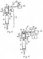
- the first and second partial volumes 1c, 1dare fluid-conductively connected via a compensation line 1e to the throttle 1f.
- the volume of liquidis preferably filled with oil.
- a gas volume 1halso referred to as a third chamber, is limited by the solid housing 1k of the hydropneumatic element 1 and a separating piston 1g, the displaceable separating piston 1g delimiting the second partial volume 1d and the gas chamber 1h.
- the upper, fixed housing 1ksurrounded by a heat exchanger 1i, to the surface of the housing 1k to to cool and thereby dissipate heat from the gas chamber 1h and from the second oil chamber 1d.
- the heat exchangeris connected to a cooling device 21 via a cooling circuit 22, comprising coolant lines 22a, 22b and possibly comprising a circulation device 22c.
- the cooling circuit 22has no active circulation device 22c, so that the flow of the fluid in the cooling circuit 22 is carried out by purely passive convection.
- the cooling circuit 22comprises an active circulation device 22c, for example a continuously running pump 22c.
- the cooling circuit 22is connected to the cooling circuit of the vehicle, so that, for example, cooling water of the vehicle cooling either directly or decoupled via an additional intermediate heat exchanger, the cooling circuit 22 flows through.
- This arrangementalso has the advantage that when starting the vehicle the heat exchanger 1i heated cooling water can be supplied, so that the gas in the gas chamber 1h, if necessary, already during starting and warming of the vehicle to a particular predetermined, current operating temperature or Reference temperature TR can be heated.
- This embodimentwith heating of the hydropneumatic element, has the advantage that the hydropneumatic element 1, as soon as the vehicle has been started, has an opening as in FIG FIG. 12 shown, defined, the temperature TR associated spring characteristic, since the hydropneumatic element 1 due to the cooling circuit has a substantially constant or in a predetermined, narrow temperature range lying operating temperature, and ideally a relatively constant reference temperature TR.
- the upper fixed housing 1kcould, as in FIG.
- the hydropneumatic element 1could additionally be provided with a sensor such as a temperature sensor 6, which is connected to a display or control device 3, not shown.
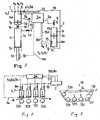
- FIG. 2shows a Hydropelement 1, which in contrast to the in FIG. 1 illustrated embodiment, an actively controlled cooling circuit 22 by a temperature sensor 6 with a Temperature is measured, for example, as shown, the temperature in the gas chamber 1h and / or the temperature of the coolant line 22a, 22b.
- This measured temperatureis supplied via a signal line 6a to a drive and / or control device 3, which controls the circulation device 22c via a signal line 22d.
- the circulation device 22cis controlled in such a way that the temperature measured with the temperature sensor 6 is substantially constant during operation of the vehicle.
- the control device 3could also be part of the engine of the vehicle, and the cooling device 21 and the circulation device 22c part of the engine cooling.
- the heat exchanger 1ican be arranged in such a way on the hydropneumatic element 1 in a plurality of ways that a heat exchange results.
- the heat exchanger 1icould, for example, also be configured as a spiral through which the fluid flows, as shown, which also runs in the interior of the gas chamber 1h.
- This heat exchanger 1inot only allows cooling of the interior of the gas chamber 1h, but also, as already above in connection with FIG. 1 described to heat the interior of the gas chamber 1h, in particular during the start or warm-up of the vehicle, especially in the early morning when the vehicle has cooled due to the previous night, and the gas in the gas chamber 1h therefore a deep, substantially below the usual operating temperature TR lying temperature.
- a heating devicein particular an electric heating device.
- spiral 1icould for example be designed as an electric heater for heating the gas.
- the temperature of the gas in the gas chamber 1hcan also be influenced.
- the throttle 1fcan be designed as a passive element or as an actively influenceable or actively controllable throttle 1f.
- the throttle 1fserves to dampen the fluid flowing back and forth between the first oil chamber part 1c and the second oil chamber part 1d, which is why a high heat output is released, particularly in the case of a rapidly deflected hydropelement at the throttle 1f, which is preferably arranged directly from one to the throttle 1f Heat exchanger 1i is discharged.
- FIG. 4 illustrated spring damping devicecomprises a hydropneumatic element 1, the first and second oil chamber part 1c, 1d are connected to each other via a longer connecting line 11.
- the throttle 1fmay be arranged in the region of the first or second oil chamber part 1c, 1d.
- This in FIG. 4 Hydropelement 1 shownhas the advantage that the first and second oil chamber part 1c, 1d can be arranged spaced from each other, even relatively far, without thereby the operating characteristics of the hydropneumatic element 1 are changed.
- Such a designed Hydropelement 1has the advantage that, for example, only the first oil chamber part 1 c, the movable piston 1 b and the connecting means 1 a outside of a vehicle must be arranged, whereas the remaining in FIG. 4 represented elements could also be arranged within the vehicle.
- FIG. 5 1schematically shows a hydropneumatic spring damping device of a vehicle having four hydraulic elements 1.
- Each hydraulic element 1comprises a heat exchanger 1i, a temperature sensor 6, and optionally a sensor 16 for position determination, preferably a position sensor or a length sensor, and a respective hydraulic element 1 associated valve 4.
- the sensor 16 for position determinationfor example, the length of the hydropneumatic element 1 or, for example, the height of the vehicle can be measured from the ground.
- the sensor 16 for position determinationcan be configured in a variety of ways to measure the position or attitude of the vehicle and / or the position of a Hydropiatas, for example, its length or its deflection.
- the cooling circuit 22which is connected to the cooling device 21, comprises the coolant lines 22a, 22b and the circulation device 22c.
- the drive device 3is connected via electrical signal lines 4a, 6a, 16b and 22d to the valves 4, the temperature sensors 6, the circulation device 22c and the optional sensor 16 for position determination.
- the heat exchanger 1i each Hydropettis 1 via the valve 4can be individually and controllably supplied with coolant, so that the temperature of each individual Hydropiatas 1 can be set individually, and in particular within a predetermined temperature range of for example TR +/- 10 ° C or can be maintained at a predetermined temperature TR.
- the sensor 16 for position determinationserves, for example, to detect the position of the hydropneumatic element 1 after cooling, for example in the early morning. For cooling itself, however, the sensor 16 for position determination is not required. For this purpose, the temperature sensor 6 and the controllable valve 4 is sufficient.
- a controllable valve 4could also be dispensed with by replacing it with a mechanical valve having a temperature sensor, eg a bimetal, wherein the temperature sensor measures, for example, the temperature of the cooling water flowing out of the heat exchanger, and the valve controls the amount of water.
- a valve with integrated temperature sensorcould be dispensed with the electrical signal lines 4a, 6a.
- FIG. 6shows a further embodiment of a hydropneumatic spring-damping device of a vehicle with four Hydropianon 1, which in contrast to the in FIG. 5 shown arrangement are connected in series such that the hydropneumatic elements 1 are flowed through successively by the same cooling liquid.
- the temperature of the cooling water in the coolant line 22bis measured with a temperature sensor 6.
- the driving and / or regulating deviceis in turn connected to the temperature sensor 6 and preferably controls the circulating device 22c such that the temperature of the cooling water is maintained at a substantially predetermined, constant temperature TR.
- FIGS. 7, 8 and 9disclose one of the same patent applicant already in the document WO 2005/073001 disclosed arrangement for supplying or discharging a quantity of gas into the interior of the gas chamber 1h. It may prove advantageous to use this arrangement in combination with in the FIGS. 1 to 6 to use shown arrangement.
- the FIGS. 7, 8 and 9show an arrangement which serves for supplying or discharging a quantity of gas into the interior of the gas chamber 1h.
- the FIGS. 1 to 6show an arrangement which serves for cooling or heating of the gas in the gas chamber 1h. It may prove advantageous to use both mutually independent methods or arrangements, for example, by first supplying a quantity of gas to the hydropneumatic element 1 in the early morning with cold hydropumps, to thereby provide, as in FIG FIG.
- the hydropneumatic element 1for example, represented by T1, the spring characteristics of the hydraulic element 1 of T1 after TR corrected or, in the reverse case, an amount of gas to be corrected from T4 to TR.
- the hydropneumatic element 1could, as with the aid of FIGS. 1 to 6 described, cooled and / or heated. If necessary, the hydropneumatic element 1 can be supplied or removed at any time with an amount of gas, in particular since the arrangement is in accordance with FIG FIGS. 5 and 6 is independent of the arrangement in the sense FIG. 8 in that both arrangements or their methods can be operated successively or simultaneously.
- a simultaneous perform both methodsis possible because with the one method, the interior of the gas chamber 1h a quantity of gas is supplied or removed, while the other method, the gas chamber 1h is preferably cooled from the outside. Both methods are thus independent of each other and, if necessary, simultaneously operable.
- the hydropneumatic element 1 shown in simplified formcomprises a vertically displaceable connecting means 1a, at the lower end of which an unillustrated wheel or wheel holder is fastened.
- the connecting means 1ais fixedly connected to a displaceably mounted piston 1b with housing part, wherein the piston 1b with housing part and the fixed housing of the hydraulic elements 1 define a liquid volume which has a first partial volume 1c and a second partial volume 1d.
- the first partial volume 1cis also referred to as the first chamber, the second partial volume 1d as the second chamber.
- the first and second sub-volumes 1c, 1dare fluid via a compensation line 1e with throttle 1f connected.
- the volume of liquidis preferably filled with oil.
- a gas volume 1halso referred to as a third chamber, is limited by the solid housing of the hydropneumatic element 1 and a separating piston 1g, the displaceable separating piston 1g delimiting the second partial volume 1d and the gas chamber 1h.
- the hydropneumatic element 1is provided with a temperature sensor 6 and with a pressure sensor 7 to measure in the gas chamber 1h the temperature T H and the pressure P H of the gas therein. Both sensors 6, 7 are connected via signal lines 6a, 7a to a drive device 3a.
- the metering cylinder 2comprises a displaceably mounted metering piston 2a, which separates an oil chamber 2b from a metered volume 2c filled with gas.
- the oil chamber 2 bis connected via a control valve 5 to an oil pressure line 9.
- the dosing cylinder 2is provided with a pressure sensor 8 and a temperature sensor 15 to measure in the dosing cylinder 2, the temperature and the pressure of the gas therein.
- the pressurecan fluctuate greatly, for example during the drive of the tracked vehicle. Nevertheless, in order to reliably measure the pressure value, the drive device 3a preferably forms an average value during a specific period of time.
- Both sensors 8, 15 and the control valve 5are connected via signal lines 8a, 15a, 5a with the drive device 3a.
- the control valve 5can be controlled, for example, by means of a time control by the control valve 5 is opened during a predetermined period of time, so as to supply or remove a defined amount of oil of the oil chamber 2b.
- the FIG. 1 shown arrangementcould also only a temperature sensor. 6 or a pressure sensor 7, if that would be enough to calculate or determine a correction volume Vk.
- nitrogenis used as the gas.
- a position or length measuring device 16is connected via signal lines 16b to the drive device 3a.
- a position measurementcan be made directly on or in the hydropneumatic element 1, or the position can be determined by measuring the angle of rotation of the support arm. It could, for example, the height of the tracked vehicle from the ground are measured, and from this value, the position or length of the hydropneumatic element 1 are derived.
- the position measurement 16 together with a pressure measurement 7is used to assess the actual characteristic as a function of the temperature of the gas accordingly Fig. 12 , With the control device 3a and the metering device 2, the gas volume in the gas chamber 1h can be tracked such that a predetermined characteristic according to Fig. 12 can always be adjusted independently of the temperature of the gas.
- each hydropneumatic element 1is connected to a wheel 12a, 12b, 12c, 12d, as well as a position sensor 16 and optionally a temperature sensor 6 and optionally a pressure sensor 7.
- Each individual hydropneumatic element 1can be connected to the metering cylinder 2 via a control valve 4b and a common feed line 10.
- Each hydropneumatic element 1 and the metering cylinder 2are signal-connected to the control device 3a in order to control the control valves 4b of the hydraulic elements 1 and the metering cylinder 2 by the control device 3a.
- a vehiclecould for example have two, four, six or eight wheels 12a, 12b, 12c, 12d, which are each connected via a hydropneumatic element 1 to the vehicle frame of the vehicle. So could For example, an off-road wheeled vehicle on each side four in the direction of travel successively arranged wheels 12a, 12b, 12c, 12d with hydraulic elements 1 have.
- each hydraulic element 1has its own metering device 2.
- the position or length measurement 16is preferably carried out separately for each hydropneumatic element 1.
- Each measuring device 16is connected via a signal line 16b to the drive device 3a, wherein in FIG. 8 only one of the signal lines 16b is shown.
- the position measurement 16 on at least one or two hydropneumatic elements 1, eg on the foremost or rearmost hydropneumatic element 1,is sufficient.
- the position or length of the hydro-pneumatic elements 1 arranged therebetweencan be calculated by interpolation, so that also an approximate value regarding the length of these intermediate hydropneumatic elements 1 is available, so that these can also be supplied by the metering device 2 with a correction volume of gas Vk.
- FIG. 9shows schematically a chain drive of a tracked vehicle, wherein the circulating chain 14 of the rollers 12a, 12b, 12c, 12d and the guide rollers 13a, 13b is supported.
- the pulleys 13a, 13bare referred to in Ketthusen as a stator or drive wheel.
- the rollers 12b, 12care connected via a respective hydropneumatic element 1 with a common drive carrier 17 and mounted displaceably in the direction shown.
- the wheels 12a and 12dhave no hydraulic elements 1 and are connected to the drive carrier 17, for example, with a conventional mechanical spring.
- the tension of the chain 14can be influenced by the hydraulic elements 1 connected to the rollers 12b, 12c.
- all rollers 12a, 12b, 12c, 12dare each connected via a hydropneumatic element 1 to the drive carrier 17, wherein at least one of the hydraulic elements 1 is fluidically connected to a metering device 2 and thus the gas chamber 1h of the hydraulic elements 1 can be supplied with a compensation volume can be discharged, whereas the remaining Hydrop implant 1 have no fluid-conducting connection to a metering device 2, so that the respective gas chamber 1h of these Hydrop implant 1 no compensation volume Vk can be fed and these Hydropetti 1 are not controlled.
- these non-controllable hydraulic elements 1include a temperature and / or pressure sensor 6,7 for determining the temperature and / or the pressure of the gas in the respective gas chamber 1h.
- the state of the non-controllable hydraulic elements 1is taken into account by measuring their temperature and / or pressure, and the compensation volume is calculated in such a way that the tracked vehicle has in particular a predetermined height and / or a predetermined chain tension .
- the tracked vehiclecomprises in the FIGS. 5 or 6 illustrated arrangement, and possibly additionally in the FIGS. 7 and 8 illustrated arrangement.
- the hydropneumatic spring damping devicehas the advantage that the heat exchanger 1i ensures that the hydropneumatic element 1 is kept at a preferably constant operating temperature during operation. It can therefore prove to be advantageous in the FIGS. 7 to 9 described arrangement for supplying or discharging a quantity of gas into the interior of the gas chamber 1 h to simplify that simply a certain amount of gas of the gas chamber 1h, in particular a predetermined amount, is added or removed. Preferably, neither the pressure nor the temperature in the gas chamber 1h is measured. The information of the sensor 16 for position measurement is sufficient in itself to decide whether a certain amount of gas to the gas chamber 1h to be added or removed. This allows the in FIG. 7 significantly simplify the arrangement shown.
- Thiscan be done in place of the supply of gas into the gas chamber 1h.
- Both the supply of gas into the gas chamber 1h and the supply of oil into the first or second oil chamber part 1c, 1dcauses the characteristic of the hydraulic element to be changed by adjusting the spring characteristic with respect to the static zero position.
- a quantity of oil and / or gascan be added or removed from the hydropneumatic element 1 several times.
- FIG. 10schematically shows a plan view of a vehicle having a drive 18 left and right, each drive 18 comprises at least one Hydropelement 1, on each of which a wheel or an impeller is arranged for a chain.
- the vehicleincludes an engine cooling system 24, which is connected to the cooling device 21 via a coolant circuit forming coolant lines 24a, 24b.
- the cooling device 21is in turn via coolant lines 22a, 22b, for example, as in the FIGS. 5 and 6 shown connected to the individual Hydropelement 1.
- a drive device 3controls the cooling of the hydraulic elements 1.
- the vehiclecould also include a gas compensation drive device 3a, which, as with the aid of FIGS. 7 and 8 described, the gas chamber 1h a compensation volume increases or dissipates.
- FIG. 11shows an embodiment of the in FIG. 1
- a hydraulic lever 19is rotatably connected to the common drive carrier 17 at the point 19a and connected to the wheel 12b at the point 19c.
- the hydropneumatic element 1is rotatably connected to the common drive carrier 17 at the point 20 and rotatably connected to the lever arm 19 at the point 19b.
- the wheel 12bis spring mounted with respect to the common drive carrier 17 in the vertical direction, wherein the wheel 12b, a force F2 attacks, resulting in the hydropneumatic element 1 a reaction force F1 result.
- FIG. 13shows a further hydropneumatic spring-damping device, wherein, in contrast to the in FIG. 7 illustrated embodiment, the first and / or second oil chamber part 1c, 1d at least one Hydropiatas 1 via an Oldosiervoriques 4c an oil compensation volume Vk is added or removed.
- the oil metering device 4 cis fluidly connected to an oil supply 9.
- the oil metering device 4cis shown in simplified form as a valve, wherein the oil metering device 4c is preferably designed as a device comprising a piston and a cylinder, so that a defined oil compensation volume Vk can be supplied or discharged.
- the arrangementis preferably operated in such a way, with a sensor 16 for position determination, in particular for detecting the length w of the hydraulic element 1 or the rotation of the hydropneumatic element 1 with respect to a reference position, the position of the hydropneumatic element 1 or the position of the entire vehicle is detected, and that the Compensating drive device 3a is designed such that it controls the oil metering device 4c such that the first and / or second oil chamber part 1c, 1d, an oil compensation volume Vk is zumarinbar or be discharged.
- the position of the hydropneumatic elements 1 or the position of the entire vehicleis changed, because the added or removed oil compensation volume Vk causes the in FIG. 12 displayed curve is shifted.
- the heat exchanger 1i acting on the gas chamber 1h of the hydropneumatic element 1has the consequence that the hydropneumatic element 1 has an essentially constant temperature after warming up in an advantageous mode of operation, so that the position of the entire vehicle can be controlled very simply such that FIG. 13 shown, an oil compensation volume Vk the first and / or second Oil chamber part 1c, 1d added or removed, or by, as in FIG. 7 shown, a gas compensation volume Vk of the gas chamber 1h is added or removed.
- the sensor 16 for determining the position of the hydropneumatic element 1 or of the vehicledetects a deviation from a nominal value
- thiscan be corrected by an additionally supplied or removed oil or gas compensation volume Vk, so that the vehicle essentially assumes a predetermined position even with very rapidly occurring temperature changes can comply.
- the hydropneumatic element 1will usually heat up again, so that the sensor 16 for determining the position of the hydropneumatic element 1 or of the vehicle will detect a deviation from the nominal value, and therefore the position by an additionally supplied or removed oil or gas compensation volume Vk can be corrected.
- An oil compensation volume Vkmay be supplied to the first and / or second oil chamber parts 1c, 1d or a gas compensation volume Vk not only to the gas volume 1h of the hydropneumatic element 1, if a positional change is detected. It is also possible that over the temperature sensor 6 or the pressure sensor 7 is determined to be too low or too high a value, and that then a compensation volume Vk the first and / or second oil chamber part 1c, 1d and / or the gas volume 1h is added or removed. If such a too low or too high value is determined, so in the simplest embodiment, a fixed predetermined compensation volume Vk be added or removed.
- the method according to the inventionthus enables a multiplicity of methods for keeping the temperature in the hydropneumatic element preferably substantially constant or in a predetermined temperature range and for supplying an oil compensation volume Vk to the first and / or second oil chamber part 1c, 1d or to a gas compensation volume Supply Vk the gas volume 1h of the hydropneumatic element in order to influence by these measures the position of the hydropneumatic element and / or the position of the vehicle.
Landscapes
- Engineering & Computer Science (AREA)
- Mechanical Engineering (AREA)
- General Engineering & Computer Science (AREA)
- Vehicle Body Suspensions (AREA)
Description
Translated fromGermanDie Erfindung betrifft eine hydropneumatische Feder-Dämpfungsvorrichtung gemäss dem Oberbegriff von Anspruch 1. Die Erfindung betrifft weiter ein Verfahren zum Betreiben einer hydropneumatischen Feder-Dämpfungsvorrichtung gemäss dem Oberbegriff von Anspruch 15.The invention relates to a hydropneumatic spring-damping device according to the preamble of
Eine hydropneumatische Feder-Dämpfungsvorrichtung umfasst im Allgemeinen ein Gasvolumen und ein Flüssigkeitsvolumen, die über einen Trennkolben in einer festen Gehäusekombination aufgenommen sind. Die hydropneumatische Feder-Dämpfungsvorrichtung umfasst drei Kammern. Eine erste Kammer ist für die Aufnahme von Flüssigkeitsvolumen bestimmt. Dieses Flüssigkeitsvolumen ist veränderbar, indem Gehäuseteile in irgendeiner Art und Weise zusammengeschoben oder auseinandergeschoben werden. Eine zweite Kammer ist mit der ersten Kammer über eine Drossel fluidleitend verbunden. Die zweite Kammer ist für die Aufnahme bzw. Abgabe der Flüssigkeit von bzw. an die erste Kammer vorgesehen. Das Flüssigkeitsvolumen der ersten Kammer und der zweiten Kammer zusammen ist konstant. Die dritte Kammer ist mit einem komprimierbaren Medium, wie zum Beispiel Gas, gefüllt. Die dritte Kammer ist durch ein Trennelement, beispielsweise einem beweglichen Kolben oder einer Membrane von der zweiten Kammer getrennt.A hydropneumatic spring-damper device generally includes a volume of gas and a volume of fluid received in a fixed housing combination via a separator piston. The hydropneumatic spring-damper device comprises three chambers. A first chamber is designed to receive fluid volume. This volume of liquid is variable by sliding or sliding housing parts in some way. A second chamber is fluid-conductively connected to the first chamber via a throttle. The second chamber is provided for receiving or discharging the liquid from or to the first chamber. The liquid volume of the first chamber and the second chamber together is constant. The third chamber is filled with a compressible medium, such as gas. The third chamber is by a separating element, for example, a movable piston or a membrane separated from the second chamber.
Die hydropneumatische Feder-Dämpfungsvorrichtung ist beispielsweise einerseits am Rahmen eines Fahrzeuges und andererseits an einer beweglichen Achse oder einer beweglichen Radaufhängung befestigbar. Eine Bewegung zwischen den beiden Befestigungspunkten bewirkt eine Volumenänderung der ersten Kammer. Dadurch wird das Medium in der dritten Kammer über die zweite Kammer komprimiert bzw. dekomprimiert. Dies bewirkt eine Ein- oder Ausfederung. Die Bewegung wird insbesondere durch das über die Drossel fliessende Fluid gedämpft, indem das Fluid über die Drossel zwischen der ersten Kammer und der zweiten Kammer hin-und herströmt. Eine derartige hydropneumatische Feder-Dämpfungsvorrichtung wird auch als Hydropfeder oder Hydropelement bezeichnet. Nachfolgend wird der Begriff Hydropelement verwendet.The hydropneumatic spring damping device can be fastened, for example, on the one hand to the frame of a vehicle and, on the other hand, to a movable axle or a movable wheel suspension. A movement between the two attachment points causes a change in volume of the first chamber. As a result, the medium in the third chamber is compressed or decompressed via the second chamber. This causes a compression or rebound. In particular, the movement is damped by the fluid flowing through the throttle, in that the fluid flows back and forth between the first chamber and the second chamber via the throttle. Such a hydro-pneumatic spring-damping device is also referred to as a hydropneumatic spring or hydropneumatic element. The term Hydropelement is used below.
Nachteilig an mit Hydropelementen ausgestatteten Fahrzeugen ist die Tatsache, dass sich das Federungsverhalten der einzelnen Hydropelemente auf Grund von Umwelteinflüssen wie Temperaturänderungen oder unterschiedlichen Betriebszuständen verändern kann, auch während des Betriebs, was zur Folge hat, dass sich zum Beispiel das Fahrverhalten und/oder die Fahrzeughöhe des Fahrzeuges verändern kann. Diese Effekte treten insbesondere bei geländegängigen Fahrzeugen auf, bei welchen die Hydropelemente auf Grund der Unebenheiten des Untergrundes einer besonders starken Belastung ausgesetzt sind. Besonders nachteilig wirken sich diese Effekte bei mit Hydropelementen ausgerüsteten Kettenfahrzeugen aus, weil diese Effekte zudem noch die Spannung der Kette beeinflussen. Die Veränderung der Kettspannung kann bei Überhöhung der Kettspannung einen erhöhten Verschleiss der Kette zur Folge haben, oder bei zu loser Kette die Ursache für einen Kettenabwurf oder eine Nichtlenkbarkeit bzw. eine Nichtbremsbarkeit des Fahrzeuges sein.A disadvantage of equipped with hydropneumatic vehicles is the fact that the suspension behavior of the individual hydraulic elements may change due to environmental influences such as temperature changes or different operating conditions, even during operation, with the result that, for example, the driving behavior and / or the vehicle height of the vehicle can change. These effects occur especially in all-terrain vehicles, in which the hydropneumatic elements are exposed to a particularly heavy load due to the unevenness of the ground. These effects have a particularly disadvantageous effect on tracked vehicles equipped with hydropneumatic elements, because these effects also influence the tension of the chain. The change in the warp tension can lead to increased wear of the warp when the warp tension is increased or, if the warp is too loose, the cause of a warp Chain drop or a Nichtlenkbarkeit or a non-braking ability of the vehicle.
Die Druckschrift
Die Druckschrift
Weitere elemente hydropneumatische Feder-Dämpfervorrichtungen sind aus den
Es ist daher die Aufgabe der vorliegenden Erfindung eine hydropneumatische Feder-Dämpfungsvorrichtung sowie ein Verfahren zum Betrieb einer hydropneumatischen Feder-Dämpfungsvorrichtung vorzuschlagen, die ein vorteilhafteres Hydropelement aufweisen.It is therefore the object of the present invention to propose a hydropneumatic spring-damping device and a method for operating a hydropneumatic spring-damping device, which have a more advantageous hydropneumatic element.
Diese Aufgabe wird gelöst mit einer hydropneumatischen Feder-Dämpfungsvorrichtung aufweisend die Merkmale von Anspruch 1. Die Aufgabe wird weiter gelöst mit einem Verfahren zum Betrieb einer hydropneumatischen Feder-Dämpfungsvorrichtung aufweisend die Merkmale von Anspruch 15. Vorteilhafte Ausführungsformen ergeben sich aus den Unteransprüchen.This object is achieved with a hydropneumatic spring damping device comprising the features of
Diese Aufgabe wird insbesondere gelöst mit einer hydropneumatischen Feder-Dämpfungsvorrichtung umfassend zumindest ein Hydropelement mit einer Gaskammer, wobei das Hydropelement einen Wärmetauscher umfasst, welcher derart angeordnet ist, dass dieser die Temperatur des Gases in der Gaskammer beeinflusst, wobei der Wärmetauscher über einen Kühlkreislauf mit einer Kühlvorrichtung verbunden ist.This object is achieved in particular with a hydropneumatic spring damping device comprising at least one hydraulic element with a gas chamber, the hydraulic element comprising a heat exchanger which is arranged such that it influences the temperature of the gas in the gas chamber, wherein the heat exchanger via a cooling circuit with a Cooling device is connected.
In einer besonders vorteilhaften Ausgestaltung ist die Gaskammer und/oder die Kammer enthaltend das Flüssigkeitsvolumen mit einer Wärmetauscher verbunden, welcher beispielsweise an der Aussenwand der Kammer angeordnet ist, oder innerhalb der Kammer verlaufend angeordnet ist. Falls der Wärmetauscher direkt an der Gaskammer angeordnet ist, so kann dieser Gaskammer mit Hilfe des Wärmetauschers direkt Wärme entzogen werden. Falls der Wärmetauscher nur an der Kammer des Flüssigkeitsvolumens angeordnet ist, so entzieht der Wärmetauscher der Flüssigkeit Wärme, was wiederum zur Folge hat, dass die Temperatur des Gases in der Gaskammer beeinflusst wird, und insbesondere gekühlt wird.In a particularly advantageous embodiment, the gas chamber and / or the chamber containing the liquid volume with a Heat exchanger connected, which is arranged for example on the outer wall of the chamber, or arranged to extend within the chamber. If the heat exchanger is arranged directly on the gas chamber, then this gas chamber can be withdrawn directly by means of the heat exchanger heat. If the heat exchanger is arranged only on the chamber of the liquid volume, so the heat exchanger removes heat from the liquid, which in turn has the consequence that the temperature of the gas is influenced in the gas chamber, and in particular cooled.
Wenn ein mit Hydropelementen ausgestattetes Fahrzeug über ein unebenes Gelände fährt, so hat dies zur Folge, dass die Hydropelemente relativ rasch und gegebenenfalls auch mit langen Federwegen ausgelenkt, das heisst verlängert und verkürzt werden. Diese Bewegung der Hydropelemente hat zur Folge, dass sich die Hydropelemente auf eine aktuelle Betriebstemperatur erwärmen, insbesondere auf Grund der am Hydropelement entstehenden Reibungswärme und/oder der an der Drossel entstehenden Dämpfungswärme. Zudem hat der während dem Ein- und Ausfedern des Hydropelementes auftretende Energieaustausch im Gas der Gaskammer zur Folge, dass die Flüssigkeit und insbesondere jedoch das Gas in dem Hydropelement einer ständigen, raschen Temperaturschwankung unterliegt, die der aktuellen Betriebstemperatur überlagert ist. Diese raschen Temperaturschwankungen können die aktuelle Betriebstemperatur des Hydropelementes, beispielsweise die Temperatur des Gehäuses des Hydropelementes, zusätzlich beeinflussen. Der auf das Hydropelement wirkende Wärmetauscher kombiniert mit der Kühlvorrichtung hat zur Folge, dass die aktuelle Betriebstemperatur reduziert wird, was zur Folge hat, dass die Temperatur des Gasvolumens reduziert wird, und somit das Hydropelement in einem definierten Betriebszustand gehalten wird, beziehungsweise dass die Temperatur des Gases in der Gaskammer in einem vorherbestimmten Temperaturbereich gehalten wird.When a vehicle equipped with hydropneumatic elements travels over uneven terrain, the consequence of this is that the hydropneumatic elements are deflected, ie lengthened and shortened, relatively quickly and possibly also with long spring travel. As a result of this movement of the hydraulic elements, the hydraulic elements are heated to a current operating temperature, in particular due to the frictional heat generated at the hydropneumatic element and / or the damping heat generated at the throttle. In addition, the energy exchange occurring in the gas of the gas chamber during the compression and rebound of the hydropneumatic element has the consequence that the liquid and in particular the gas in the hydropneumatic element is subject to a constant, rapid temperature fluctuation, which is superimposed on the current operating temperature. These rapid temperature fluctuations can additionally influence the current operating temperature of the hydropneumatic element, for example the temperature of the housing of the hydropneumatic element. The heat exchanger acting on the hydropneumatic combined with the cooling device causes the current operating temperature is reduced, which has the consequence that the temperature of the gas volume is reduced, and thus the hydropneumatic element is maintained in a defined operating condition, or that the temperature of the Gas is kept in the gas chamber in a predetermined temperature range.
Die aktuelle Betriebstemperatur des Hydropelementes wird bestimmt durch diejenigen Vorgänge, welche dem Hydropelement Wärme zuführen und diejenigen Vorgänge, welche dem Hydropelement Wärme entziehen. Die aktuelle Betriebstemperatur, z.B. die am Gehäuse der Gaskammer gemessene Temperatur, stellt sich somit ein auf Grund derjenigen thermischen Vorgänge, die einen bleibenden Energieeintrag bzw. einen bleibenden Energieentzug am Hydropelement bewirken. Innerhalb der Gaskammer weist das Gas eine Gastemperatur auf, welche bei aktiv bewegtem Hydropelement einer ständigen, raschen Temperaturschwankung unterliegt, wobei die bewegungsbedingte Temperaturschwankung üblicherweise um den Wert der aktuellen Betriebstemperatur schwankt, beziehungsweise der aktuellen Betriebstemperatur überlagert ist.The actual operating temperature of the hydropneumatic element is determined by those processes which add heat to the hydropneumatic element and those processes which remove heat from the hydropneumatic element. The current operating temperature, e.g. the temperature measured at the housing of the gas chamber, thus sets itself on the basis of those thermal processes that cause a permanent energy input or a permanent energy withdrawal at the Hydropelement. Within the gas chamber, the gas has a gas temperature, which is subject to constant, rapid temperature fluctuation when the hydropelement is actively moved, wherein the movement-related temperature fluctuation usually fluctuates around the value of the current operating temperature or is superimposed on the current operating temperature.
In einer Ausführungsform ist der Kühlkreislauf als passives System ausgestaltet. In einer besonders bevorzugten Ausgestaltung ist der Kühlkreislauf als ein aktiv gesteuerter Kühlkreislauf ausgestaltet, umfassend eine Fluidpumpe, einen Temperatursensor und eine Ansteuerungsvorrichtung, welche die Temperatur des Sensors misst, und die Fluidpumpe derart ansteuert, dass die aktuelle Betriebstemperatur, vorzugsweise die aktuelle Betriebstemperatur des Gases in der Gaskammer, innerhalb eines vorherbestimmten Betriebstemperaturbereiches von beispielsweise 80°C bis 100°C gehalten wird. Als Fluid ist insbesondere Wasser geeignet. Als Fluid sind jedoch auch andere Flüssigkeiten wie zum Beispiel Öl oder auch Gase geeignet.In one embodiment, the refrigeration cycle is configured as a passive system. In a particularly preferred embodiment, the cooling circuit is configured as an actively controlled cooling circuit, comprising a fluid pump, a temperature sensor and a control device, which measures the temperature of the sensor, and the fluid pump drives such that the current operating temperature, preferably the current operating temperature of the gas in the gas chamber is maintained within a predetermined operating temperature range of, for example, 80 ° C to 100 ° C. As the fluid is particularly suitable water. As fluid but other liquids such as oil or gases are suitable.
In einer vorteilhaften Ausgestaltung ist der Kühlkreislauf derart ausgestaltet, dass jedes Hydropelement individuell kühlbar ist. Der Kühlkreislauf kann jedoch auch derart ausgestaltet sein, dass die Hydropelemente seriell nacheinander mit demselben Kühlkreislauf verbunden sind, sodass die Hydropelemente seriell nacheinander vom Kühlmittel durchflossen sind. Diese Anordnung weist den Vorteil auf, dass zwischen den nacheinander geschalteten Hydropelemente ein gegenseitiger Temperaturaustausch stattfindet. Angenommen ein Fahrzeug weist auf der einen Fahrzeugseite vier hintereinander angeordnete Fahrzeugräder bzw. Laufrollen auf, welche über je ein Hydropelement mit dem Fahrzeugkasten verbunden sind. Je nach Anordnung, Ausgestaltung und befahrenem Gelände kann diese Anordnung zur Folge haben, dass das in Fahrtrichtung zuvorderst angeordnete Hydropelement die höchste Dämpfungsleistung zu erbringen hat und somit auch die höchste Wärmebelastung beziehungsweise die höchste Wärmeenergiezufuhr erfährt, wogegen die nachgeordneten Hydropelementen auf Grund der erwartungsgemässen geringeren Auslenkung der Radbewegungen eine vergleichsweise geringere Erwärmung erfahren. Der Kühlkreislauf, welcher die Hydropelemente seriell nacheinander verbindet, weist den Vorteil auf, dass zwischen den Hydropelementen ein Temperaturaustausch beziehungsweise ein Wärmeenergieaustausch stattfindet. Fliesst das Kühlmittel beispielweise von dem in Fahrtrichtung zuhinterst angeordneten Hydropelement über die nachfolgend angeordneten Hydropelemente bis zu dem in Fahrtrichtung vordersten Hydropelement, so wird das vorderste Hydropelement durch die hinteren Hydropelemente gekühlt. In einer Ausführungsform könnte auch auf eine separate Kühlvorrichtung verzichtet werden, weil gewisse der in Serie geschalteten Hydropelemente kühler sind als andere, und somit gewisse Hydropelemente als Kühlvorrichtung wirken.In an advantageous embodiment of the cooling circuit is designed such that each Hydropelement is individually cooled. However, the cooling circuit can also be configured such that the hydraulic elements are connected in series successively with the same cooling circuit, so that the hydraulic elements are flowed through in succession by the coolant. This arrangement has the advantage in that a mutual temperature exchange takes place between the successively connected hydraulic elements. Assuming a vehicle has on one side of the vehicle four successively arranged vehicle wheels or rollers, which are connected via a respective hydropneumatic with the vehicle body. Depending on the arrangement, design and terrain traveled, this arrangement may have the result that the hydro prime element arranged in the direction of travel has the highest damping performance and thus also experiences the highest heat load or the highest heat energy supply, whereas the downstream hydro elements due to the expected lower deflection the wheel movements experience a comparatively lower heating. The cooling circuit, which connects the hydraulic elements serially one after the other, has the advantage that a temperature exchange or a heat energy exchange takes place between the hydraulic elements. If, for example, the coolant flows from the hydropelement arranged at the rear in the direction of travel via the subsequently arranged hydraulic elements to the foremost hydropelement in the direction of travel, then the foremost hydropelement is cooled by the rear hydropneumatic elements. In one embodiment, a separate cooling device could also be dispensed with, because some of the series-connected hydro-pneumatic elements are cooler than others, and thus certain hydro-pneumatic elements act as cooling devices.
Der Kühlkreislauf kann in einer Vielzahl von Möglichkeiten ausgestaltet sein um Hydropelemente zu kühlen. Die Hydropelemente können einzeln, seriell nacheinander oder gegenseitig parallel mit dem Kühlkreislauf verbunden sein. Zudem können die Hydropelemente auch in Gruppen seriell oder parallel verbunden sein, und diese Gruppen wiederum einzeln, seriell nacheinander oder gegenseitig parallel mit dem Kühlkreislauf verbunden sein.The refrigeration cycle may be configured in a variety of ways to cool hydrostatic elements. The hydropneumatic elements can be connected to the cooling circuit individually, serially one after the other or parallel to one another. In addition, the hydro-pneumatic elements can also be connected in groups in series or in parallel, and these groups in turn can be connected to the cooling circuit individually, serially one after the other or mutually parallel.
Die Kühlvorrichtung kann als eine separate Kühlvorrichtung ausgestaltet sein, welche die Wärme vorzugsweise direkt mit der Umgebungsluft austauscht. In einer besonders bevorzugten Ausführungsform ist der Kühlkreislauf der Hydropelemente jedoch mit der Kühlvorrichtung des Fahrzeuges verbunden, sodass die Hydropelemente beispielweise direkt mit Kühlwasser des Kühlers des Fahrzeuges durchströmt sind. Die Motorkühlung des Fahrzeuges ist vorzugsweise derart dimensioniert, dass deren Kühlleistung zumindest so gross ist wie die zum Kühlen des Motors sowie der Hydropelemente erforderliche Kühlleistung. Üblicherweise sind die Fahrzeuge jedoch mit einem sehr leistungsfähigen Motor versehen, sodass dieser Motor eine Kühlleistung aufweist, welche wesentlich grösser ist als die zum Kühlen der Hydropelemente erforderliche Kühlleistung. Der Motorkühler des Fahrzeuges weist beispielsweise eine Kühlleistung auf, welche zumindest 5 mal so gross ist wie die gesamte, von der hydropneumatischen Feder-Dämpfungsvorrichtung erzeugbare Wärmeleistung. In einer besonders vorteilhaften Anordnung weist der Motorkühler des Fahrzeuges eine zumindest 20 mal grössere oder sogar eine zumindest 100 mal grössere Kühlleistung auf, als die von allen Hydropelementen erzeugte Wärmeleistung. Eine grosse Kühlleistung des Fahrzeuges weist den Vorteil auf, dass die zum Kühlen der Hydropelemente erforderliche Kühlleistung vergleichsweise gering ist, sodass gewährleistet ist, dass die Hydropelemente auf einer vorgesehenen Betriebstemperatur gehalten werden können.The cooling device may be configured as a separate cooling device, which preferably exchanges the heat directly with the ambient air. In a particularly preferred embodiment, however, the cooling circuit of the hydropneumatic elements is connected to the cooling device of the vehicle so that the hydropneumatic elements, for example, flow directly through cooling water of the radiator of the vehicle. The engine cooling of the vehicle is preferably dimensioned such that its cooling capacity is at least as great as the cooling power required for cooling the engine and the hydraulic elements. Usually, however, the vehicles are provided with a very powerful engine, so that this engine has a cooling capacity which is much greater than the cooling power required to cool the hydropneumatic elements. The engine radiator of the vehicle has, for example, a cooling capacity which is at least 5 times greater than the total heat output that can be generated by the hydropneumatic spring damping device. In a particularly advantageous arrangement, the engine radiator of the vehicle has an at least 20 times greater or even at least 100 times greater cooling capacity than the heat output generated by all the hydraulic elements. A large cooling capacity of the vehicle has the advantage that the cooling power required for cooling the hydraulic elements is comparatively low, so that it is ensured that the hydraulic elements can be kept at a designated operating temperature.
Die Erfindung wird nachfolgend an Hand mehrerer Ausführungsbeispiele im Detail beschrieben. Es zeigen:
Figur 1- eine schematische Ansicht eines Hydropelementes, welches mit einer Kühlvorrichtung verbunden ist;
Figur 2- eine schematische Ansicht eines Hydropelementes, welches mit einem geregelten Kühlkreislauf verbunden ist;
Figur 3- eine schematische Ansicht eines weiteren, gekühlten Hydropelementes;
- Figur 4
- eine schematische Ansicht eines weiteren, gekühlten Hydropelementes;
- Figur 5
- eine schematische Ansicht einer hydropneumatischen Feder-Dämpfungsvorrichtung eines Fahrzeuges mit einer Mehrzahl von Einzelrädern, welchen je ein Hydropelement zugeordnet ist, wobei jedes Hydropelement individuell kühlbar ist;
Figur 6- eine schematische Ansicht einer hydropneumatischen Feder-Dämpfungsvorrichtung eines Fahrzeuges mit einer Mehrzahl von Einzelrädern, welchen je ein Hydropelement zugeordnet ist, wobei die Hydropelemente in Serieschaltung kühlbar sind;
- Figur 7
- eine schematische Ansicht eines aus dem Stand der Technik bekannten Hydropelementes mit Dosierzylinder und Ansteuerungsvorrichtung;
Figur 8- eine schematische Ansicht einer aus dem Stand der Technik bekannten hydropneumatischen Feder-Dämpfungsvorrichtung einen Fahrzeuges mit einer Mehrzahl von Einzelrändern;
Figur 9- eine schematische Ansicht eines aus dem Stand der Technik bekannten Kettenfahrzeuges mit zwei Hydropelementen;
Figur 10- eine schematische Draufsicht auf ein Federmodul eines Kettenfahrzeuges mit zwei ansteuerbaren Hydropelementen;
Figur 11- ein Ausführungsbeispiel einem Hydropelement.
Figur 12- der Zusammenhang zwischen der Länge eines Hydropelementes und dem Druck in deren Gaskammer bei einer Referenztemperaturen und weiteren Temperaturen;
- Figur 13
- eine schematische Ansicht eines Hydropelementes mit Dosierzylinder und Ansteuerungsvorrichtung.
- FIG. 1
- a schematic view of a Hydropelementes, which is connected to a cooling device;
- FIG. 2
- a schematic view of a Hydropelementes, which is connected to a controlled cooling circuit;
- FIG. 3
- a schematic view of another, cooled Hydropelementes;
- FIG. 4
- a schematic view of another, cooled Hydropelementes;
- FIG. 5
- a schematic view of a hydropneumatic spring-damping device of a vehicle having a plurality of individual wheels, which is associated with each one Hydropelement, each Hydropelement is individually coolable;
- FIG. 6
- a schematic view of a hydropneumatic spring-damping device of a vehicle having a plurality of individual wheels, each associated with a Hydropelement, the Hydropelemente are coolable in series connection;
- FIG. 7
- a schematic view of a known from the prior art Hydropelementes with dosing and drive device;
- FIG. 8
- a schematic view of a known from the prior art hydropneumatic spring damping device a vehicle with a plurality of individual edges;
- FIG. 9
- a schematic view of a known from the prior art tracked vehicle with two Hydropelementen;
- FIG. 10
- a schematic plan view of a spring module of a tracked vehicle with two controllable Hydropelementen;
- FIG. 11
- an embodiment of a hydraulic element.
- FIG. 12
- the relationship between the length of a hydropneumatic element and the pressure in its gas chamber at reference temperatures and other temperatures;
- FIG. 13
- a schematic view of a Hydropelementes with dosing and drive device.
Die in
Vorzugsweise weist die Fahrzeugkühlung eine wesentlich höhere Kühlleistung auf als die vom Hydropelement erzeugte Wärmeleistung, was zur Folge hat, dass der Wärmetauscher li und somit auch das Gas in der Gaskammer 1h in einem im Wesentlichen durch die Fahrzeugkühlung bestimmten mittleren Temperaturbereich gehalten wird. Diese Anordnung weist den zusätzlichen Vorteil auf, dass die Fahrzeugkühlung üblicherweise bereits eine Temperaturregelung aufweist, welche die Temperatur des Kühlwassers in einem üblicherweise vorherbestimmten Temperaturbereich hält. Durch die Verwendung des Kühlwassers der Fahrzeugkühlung steht auch dem Hydropelement 1 ein Kühlwasser mit einer im Wesentlichen vorherbestimmten Temperatur zur Verfügung. Durch die Verwendung der Fahrzeugkühlung ist daher in einer vorteilhaften Ausgestaltung keine aufwendige, separate Kühlvorrichtung zur Kühlung der Hydropelemente 1 erforderlich. Diese Anordnung weist zudem den Vorteil auf, dass beim Starten des Fahrzeuges dem Wärmetauscher 1i erwärmtes Kühlwasser zugeführt werden kann, sodass das Gas in der Gaskammer 1h, falls erforderlich, bereits während dem Starten und Warmlaufen des Fahrzeuges auf eine insbesondere vorherbestimmte, aktuelle Betriebstemperatur beziehungsweise die Referenztemperatur TR erwärmt werden kann. Diese Ausgestaltung mit Erwärmung des Hydropelementes weist den Vorteil auf, dass das Hydropelement 1 sehr bald nach dem Starten des Fahrzeuges eine wie in
Der Wärmetauscher 1i kann in einer Mehrzahl von Möglichkeiten derart am Hydropelement 1 angeordnet sein, dass sich ein Wärmeaustausch ergibt. Der Wärmetauscher 1i könnte beispielsweise auch wie dargestellt als Fluid durchflossene Spirale ausgestaltet sein, welche auch im Innenraum des Gaskammer 1h verläuft. Dieser Wärmetauscher 1i ermöglicht nicht nur eine Kühlung des Innenraumes der Gaskammer 1h, sondern kann auch, wie bereits oben im Zusammenhang mit
Bei der in
Die in
Die
Zum besseren Verständnis werden die
Die in
Die in
Für die Dosieraufgaben an den einzelnen Hydropelementen 1 können auch mehrere Dosiervorrichtungen 2 eingesetzt werden. Bevorzugt hat jedes Hydropelement 1 eine eigene Dosiervorrichtung 2.For the metering tasks on the individual
Die Lage- bzw. Längenmessung 16 erfolgt bevorzugt für jedes Hydropelement 1 separat. Jede Messvorrichtung 16 ist über eine Signalleitung 16b mit der Ansteuervorrichtung 3a verbunden, wobei in
In einer vorteilhaften Ausgestaltung umfassen auch diese nicht ansteuerbaren Hydropelemente 1 einen Temperatur- und/oder Drucksensor 6,7 zur Bestimmung der Temperatur und/oder des Druckes des Gases in der jeweiligen Gaskammer 1h. Bei der Berechnung des Kompensationsvolumens für die ansteuerbaren Hydropelemente 1 wird der Zustand der nicht ansteuerbaren Hydropelemente 1 über die Messung von deren Temperatur und/oder Druck berücksichtigt, und das Kompensationsvolumen derart berechnet, dass das Kettenfahrzeug insbesondere eine vorgegebene Höhe und/oder eine vorgegebene Kettenspannung aufweist. In einer weiteren vorteilhaften Ausgestaltung umfasst das Kettenfahrzeug die in den
Die erfindungsgemässe hydropneumatische Feder-Dämpfungsvorrichtung weist den Vorteil auf, dass der Wärmetauscher 1i gewährleistet, dass das Hydropelement 1 während dem Betrieb auf einer vorzugsweise konstanten Betriebstemperatur gehalten wird. Es kann sich deshalb als vorteilhaft erweisen, die in den
Ein Ölkompensationsvolumen Vk kann dem ersten und/oder zweiten Ölkammerteil 1c, 1d beziehungsweise ein Gaskompensationsvolumen Vk kann dem Gasvolumen 1h des Hydropelementes 1 nicht nur dann zugeführt werden, wenn eine Positionsveränderung festgestellt wird. Ebenfalls möglich ist, dass über den Temperatursensor 6 oder den Drucksensor 7 eine zu tiefer oder ein zu hoher Wert festgestellt wird, und dass daraufhin ein Kompensationsvolumen Vk dem ersten und/oder zweiten Ölkammerteil 1c,1d und/oder dem Gasvolumen 1h zu- oder abgeführt wird. Falls ein derartiger zu tiefer oder zu hoher Wert festgestellt wird, so kann in der einfachsten Ausführungsform ein fest vorgegebenes Kompensationsvolumen Vk zu- oder abgeführt werden. In einer anspruchsvolleren Ausführungsform stehen Informationen bezüglich dem Zusammenhang von Temperatur und Kompensationsvolumen Vk beziehungsweise von Druck und Kompensationsvolumen Vk zur Verfügung, zum Beispiel in Form einer Tabelle. Es wird beispielweise die aktuelle Temperatur oder der aktuelle Druck gemessen, wobei eine gewünschte Temperatur oder ein gewünschter Druck vorgegeben ist, sodass auf Grund des aktuellen Wertes und des gewünschten Wertes aus der Tabelle ein Kompensationsvolumen Vk ermittelt werden kann, das zu- oder abgeführt wird. In der einfachsten Ausführungsform ist für dieses Kompensationsverfahren keine Information des Sensors 16 zur Positionsbestimmung erforderlich. In einem weiteren, anspruchsvolleren Verfahren kann natürlich zusätzlich, die Information des Sensors 16 zur Positionsbestimmung verwendet werden, um die genaue Lage des Hydropelementes oder des Fahrzeuges zu bestimmen. Das erfindungsgemässe Verfahren ermöglicht somit eine Vielzahl von Verfahren, um einerseits die Temperatur in Hydropelement vorzugsweise im Wesentlichen konstant oder in einem vorherbestimmten Temperaturbereich zu halten, und um andererseits ein Ölkompensationsvolumen Vk dem ersten und/oder zweiten Ölkammerteil 1c,1d zuzuführen, beziehungsweise um ein Gaskompensationsvolumen Vk dem Gasvolumen 1h des Hydropelementes zuzuführen, um durch diese Massnahmen die Lage des Hydropelementes und/oder die Position des Fahrzeuges zu beeinflussen.An oil compensation volume Vk may be supplied to the first and / or second
Claims (23)
- A hydropneumatic spring-damping device, in particular for wheeled or track vehicles, comprising at least one Hydrop element (1) having a gas chamber (1 h),characterised in that the Hydrop element (1) comprises a heat exchanger (1i), wherein the heat exchanger (1i) is arranged on the Hydrop element (1) in such a manner that said heat exchanger cools the temperature of the gas in the gas chamber (1 h), and that the heat exchanger (1i) can be connected to a cooling device (21) via a cooling circuit (22).
- The hydropneumatic spring-damping device according to Claim 1,characterised in that the Hydrop element (1) comprises the gas chamber (1h) and an oil chamber (1c, 1d) and a throttle (1f), and that the gas chamber (1 h) and/or the oil chamber (1 c, 1 d) and/or the throttle (1f) is connected to the heat exchanger (1 i).
- The hydropneumatic spring-damping device according to Claim 1 or 2, comprising a temperature sensor (6) for detecting the temperature of the gas in the gas chamber (1 h) and/or the temperature of the coolant in the cooling circuit (22), and comprising a valve (4) for controlling the amount of coolant supplied to the heat exchanger (1 i), wherein the valve (4) is preferably in the form of a mechanical valve comprising a mechanical temperature sensor.
- The hydropneumatic spring-damping device according to Claim 1 or 2, comprising a temperature sensor (6) for determining the temperature of the gas in the gas chamber (1 h) and/or the temperature of the coolant in the cooling circuit (22), and comprising an actuating device (3), wherein the actuating device (3) is designed such that it detects a measurement value of the sensor (6) and, based on said measurement value, actuates the cooling circuit (22) in such a manner that the gas in the gas chamber (1 h) is kept within a previously defined temperature range.
- The hydropneumatic spring-damping device according to any one of Claims 2 to 4,characterised in that the cooling circuit (22) is designed such that at least two of the Hydrop elements (1) can be cooled individually, depending on the temperature measured by the temperature sensor (6) of the respective Hydrop element (1).
- The hydropneumatic spring-damping device according to any one of Claims 1 to 4,characterised in that the heat exchangers (1 i) of a plurality of Hydrop elements (1) are connected in series one after the other to the cooling circuit (22).
- The hydropneumatic spring-damping device according to any one of Claims 1 to 4,characterised in that the heat exchangers (1 i) of a plurality of Hydrop elements (1) are connected in parallel to one another to the cooling circuit (22).
- The hydropneumatic spring-damping device according to Claim 6 or 7,characterised in that all the Hydrop elements (1) connected to the cooling circuit (22) form the cooling device (21).
- The hydropneumatic spring-damping device according to any one of the preceding claims, wherein the gas chamber (1 h) of at least one Hydrop element (1) is flow-connected via a control valve (4) to a dosing device (2), comprising a sensor (16) for determining position, in particular for detecting the length (w) of the Hydrop element (1) or the rotation of the Hydrop element (1) in relation to a reference position, and comprising a gas compensation actuation device (3a), wherein the gas compensation actuation device (3a) is designed such that it actuates the dosing device (2) and the control valve (4) in such a manner that a compensation volume (Vk) can be supplied to or discharged from the gas chamber (1 h).
- The hydropneumatic spring-damping device according to any one of Claims 1 to 8, wherein the gas chamber (1 h) of at least one Hydrop element (1) is flow-connected via a control valve (4) to a dosing device (2), comprising a sensor (7) for determining the pressure of the gas in the gas chamber (1 h), comprising a sensor (16) for determining position, in particular for detecting the length (w) of the Hydrop element (1) or the rotation of the Hydrop element (1) in relation to a reference position, and comprising a gas compensation actuation device (3a), wherein the gas compensation actuation device (3a) is designed such that it detects the measurement values of the sensors (7, 16) and, based on said measurement values, actuates the dosing device (2) and the control valve (4) in such a manner that a compensation volume (Vk) can be supplied to or discharged from the gas chamber (1 h).
- The hydropneumatic spring-damping device according to any one of Claims 1 to 8, wherein the first and/or second oil chamber part (1 c, 1 d) of at least one Hydrop element (1) is flow-connected via an oil-dosing device (4c) to an oil supply (9), comprising a sensor (16) for determining position, in particular for detecting the length (w) of the Hydrop element (1) or the rotation of the Hydrop element (1) in relation to a reference position, and comprising a gas compensation actuation device (3a), wherein the gas compensation actuation device (3a) is designed such that it actuates the oil-dosing device (4c) in such a manner that an oil compensation volume (Vk) can be supplied to or discharged from the first and/or second oil chamber part (1 c, 1 d).
- The hydropneumatic spring-damping device according to any one of Claims 1 to 8, wherein the gas chamber (1 h) of at least one Hydrop element (1) is connected to a gas-dosing device (2), and/or wherein the first and/or second oil chamber part (1 c, 1d) of the at least one Hydrop element (1) is connected to an oil-dosing device (4c), and wherein a compensation volume Vk can be supplied to or discharged from the gas chamber (1 h) and/or the first and/or second oil chamber part (1 c, 1 d) depending on a measured temperature and/or depending on a measured pressure.
- The hydropneumatic spring-damping device according to any one of the preceding claims,characterised in that the heat exchanger (1 i) can be connected to a heating device in order to heat the temperature of the gas in the gas chamber (1 h).
- The hydropneumatic spring-damping device according to any one of the preceding claims,characterised in that an electric heating device is arranged such that the gas chamber (1 h) can be heated.
- A method for controlling a hydropneumatic spring-damping device, in particular the spring-damping device of a wheeled or track vehicle, comprising at least one Hydrop element (1) having a gas chamber (1 h),characterised in that the temperature of the gas in the gas chamber (1 h) is cooled with the aid of a cooling circuit (22).
- The method according to Claim 15,characterised in that at least one of the following components of the Hydrop element (1) is cooled: gas chamber (1 h), oil chamber (1c, 1d) and throttle (1f).
- The method according to Claims 15 and 16,characterised in that the gas chamber (1 h) of the Hydrop element (1) is heated when the spring-damping device is cool.
- The method according to any one of Claims 15 to 17,characterised in that at least one Hydrop element (1) can be flow-connected to a dosing device (2), wherein the pressure of the gas in the gas chamber (1 h) of the Hydrop element (1) and the length (w) of the Hydrop element (1) are measured, and wherein a compensation volume (Vk) is supplied to or discharged from the gas chamber (1 h) depending on said measured values.
- The method according to any one of Claims 15 to 17,characterised in that at least one Hydrop element (1) can be flow-connected to an oil-dosing device (4c), wherein a compensation volume (Vk) can be supplied to or discharged from the gas chamber (1 h), and wherein the position of the Hydrop element (1) or of the vehicle is then measured with a sensor (16), and a further compensation volume (Vk) is supplied or discharged if necessary.
- The method according to any one of Claims 15 to 17,characterised in that at least one Hydrop element (1) can be flow-connected to an oil-dosing device (4c), wherein a compensation volume (Vk) can be supplied to or discharged from the first and/or second oil chamber part (1 c, 1 d), and wherein the position of the Hydrop element (1) or of the vehicle is then measured with a sensor (16), and a further compensation volume (Vk) is supplied or discharged if necessary.
- The method according to any one of Claims 15 to 17,characterised in that a temperature of the Hydrop element (1) is measured and/or that a pressure of the Hydrop element (1) is measured, and that a gas compensation volume (Vk) is supplied to or discharged from the Hydrop element (1), and/or an oil compensation volume (Vk) is supplied to or discharged from the first and/or second oil chamber part (1c, 1d), depending on the measured temperature and/or on the measured pressure.
- A vehicle comprising a hydropneumatic spring-damping device according to any one of Claims 1 to 14 or operated using a method according to any one of Claims 15 to 21,characterised in that the vehicle has an engine-cooling system, the cooling power of which is at least equal to the total heating power that can be generated by the hydropneumatic spring-damping device.
- The vehicle according to Claim 22,characterised in that the engine-cooling system of the vehicle has a cooling power at least 5 times greater than the total heating power that can be generated by the hydropneumatic spring-damping device.
Priority Applications (2)
| Application Number | Priority Date | Filing Date | Title |
|---|---|---|---|
| EP07119441.9AEP2052889B1 (en) | 2007-10-26 | 2007-10-26 | Hydropneumatic spring-damping device and method of operation of a hydropneumatic spring-damping device |
| US12/112,897US8196721B2 (en) | 2007-10-26 | 2008-04-30 | Hydropneumatic spring and damper system |
Applications Claiming Priority (1)
| Application Number | Priority Date | Filing Date | Title |
|---|---|---|---|
| EP07119441.9AEP2052889B1 (en) | 2007-10-26 | 2007-10-26 | Hydropneumatic spring-damping device and method of operation of a hydropneumatic spring-damping device |
Publications (2)
| Publication Number | Publication Date |
|---|---|
| EP2052889A1 EP2052889A1 (en) | 2009-04-29 |
| EP2052889B1true EP2052889B1 (en) | 2016-06-15 |
Family
ID=38776138
Family Applications (1)
| Application Number | Title | Priority Date | Filing Date |
|---|---|---|---|
| EP07119441.9ARevokedEP2052889B1 (en) | 2007-10-26 | 2007-10-26 | Hydropneumatic spring-damping device and method of operation of a hydropneumatic spring-damping device |
Country Status (2)
| Country | Link |
|---|---|
| US (1) | US8196721B2 (en) |
| EP (1) | EP2052889B1 (en) |
Cited By (1)
| Publication number | Priority date | Publication date | Assignee | Title |
|---|---|---|---|---|
| DE102019124971A1 (en)* | 2019-09-17 | 2021-03-18 | Audi Ag | Gas piston accumulator |
Families Citing this family (42)
| Publication number | Priority date | Publication date | Assignee | Title |
|---|---|---|---|---|
| US7958731B2 (en)* | 2009-01-20 | 2011-06-14 | Sustainx, Inc. | Systems and methods for combined thermal and compressed gas energy conversion systems |
| US8479505B2 (en) | 2008-04-09 | 2013-07-09 | Sustainx, Inc. | Systems and methods for reducing dead volume in compressed-gas energy storage systems |
| US8359856B2 (en) | 2008-04-09 | 2013-01-29 | Sustainx Inc. | Systems and methods for efficient pumping of high-pressure fluids for energy storage and recovery |
| US7832207B2 (en) | 2008-04-09 | 2010-11-16 | Sustainx, Inc. | Systems and methods for energy storage and recovery using compressed gas |
| US8240140B2 (en) | 2008-04-09 | 2012-08-14 | Sustainx, Inc. | High-efficiency energy-conversion based on fluid expansion and compression |
| US20100307156A1 (en) | 2009-06-04 | 2010-12-09 | Bollinger Benjamin R | Systems and Methods for Improving Drivetrain Efficiency for Compressed Gas Energy Storage and Recovery Systems |
| US8448433B2 (en) | 2008-04-09 | 2013-05-28 | Sustainx, Inc. | Systems and methods for energy storage and recovery using gas expansion and compression |
| US8250863B2 (en) | 2008-04-09 | 2012-08-28 | Sustainx, Inc. | Heat exchange with compressed gas in energy-storage systems |
| US8225606B2 (en) | 2008-04-09 | 2012-07-24 | Sustainx, Inc. | Systems and methods for energy storage and recovery using rapid isothermal gas expansion and compression |
| US8677744B2 (en) | 2008-04-09 | 2014-03-25 | SustaioX, Inc. | Fluid circulation in energy storage and recovery systems |
| US8474255B2 (en) | 2008-04-09 | 2013-07-02 | Sustainx, Inc. | Forming liquid sprays in compressed-gas energy storage systems for effective heat exchange |
| US8037678B2 (en) | 2009-09-11 | 2011-10-18 | Sustainx, Inc. | Energy storage and generation systems and methods using coupled cylinder assemblies |
| WO2009152141A2 (en) | 2008-06-09 | 2009-12-17 | Sustainx, Inc. | System and method for rapid isothermal gas expansion and compression for energy storage |
| US7963110B2 (en)* | 2009-03-12 | 2011-06-21 | Sustainx, Inc. | Systems and methods for improving drivetrain efficiency for compressed gas energy storage |
| US8104274B2 (en) | 2009-06-04 | 2012-01-31 | Sustainx, Inc. | Increased power in compressed-gas energy storage and recovery |
| DE102009032897B4 (en)* | 2009-07-10 | 2013-09-19 | Stabilus Gmbh | Piston-cylinder assembly |
| WO2011056855A1 (en) | 2009-11-03 | 2011-05-12 | Sustainx, Inc. | Systems and methods for compressed-gas energy storage using coupled cylinder assemblies |
| US8171728B2 (en) | 2010-04-08 | 2012-05-08 | Sustainx, Inc. | High-efficiency liquid heat exchange in compressed-gas energy storage systems |
| US8191362B2 (en) | 2010-04-08 | 2012-06-05 | Sustainx, Inc. | Systems and methods for reducing dead volume in compressed-gas energy storage systems |
| US8234863B2 (en)* | 2010-05-14 | 2012-08-07 | Sustainx, Inc. | Forming liquid sprays in compressed-gas energy storage systems for effective heat exchange |
| DE102011009079B4 (en)* | 2010-06-09 | 2021-10-07 | Rheinmetall Landsysteme Gmbh | Hydropic element |
| US8495872B2 (en) | 2010-08-20 | 2013-07-30 | Sustainx, Inc. | Energy storage and recovery utilizing low-pressure thermal conditioning for heat exchange with high-pressure gas |
| DE102010051663A1 (en)* | 2010-11-17 | 2012-05-24 | Liebherr-Hydraulikbagger Gmbh | implement |
| DE102010051650A1 (en)* | 2010-11-17 | 2012-05-24 | Liebherr-Hydraulikbagger Gmbh | implement |
| DE102010051664A1 (en)* | 2010-11-17 | 2012-05-24 | Liebherr-Hydraulikbagger Gmbh | implement |
| US8578708B2 (en) | 2010-11-30 | 2013-11-12 | Sustainx, Inc. | Fluid-flow control in energy storage and recovery systems |
| EP2495472B1 (en) | 2011-03-03 | 2024-05-01 | Fox Factory, Inc. | Cooler for a suspension damper |
| JP2014522460A (en) | 2011-05-17 | 2014-09-04 | サステインエックス, インコーポレイテッド | System and method for efficient two-phase heat transfer in a compressed air energy storage system |
| US20130091836A1 (en) | 2011-10-14 | 2013-04-18 | Sustainx, Inc. | Dead-volume management in compressed-gas energy storage and recovery systems |
| US8641053B2 (en)* | 2012-02-27 | 2014-02-04 | Bose Corporation | Actuator assembly |
| US9303715B2 (en) | 2013-03-10 | 2016-04-05 | Oshkosh Defense, Llc | Limiting system for a vehicle suspension component |
| DE112014001904B4 (en)* | 2013-04-10 | 2023-06-15 | Tenneco Automotive Operating Company Inc. | level control system |
| US9944145B2 (en) | 2014-04-11 | 2018-04-17 | Oshkosh Defense, Llc | Suspension element |
| US20160228289A1 (en)* | 2015-02-11 | 2016-08-11 | Jeffrey T. Mason | Cold therapy device with thermo-mechanical mixing valve |
| CN106120915A (en)* | 2016-08-24 | 2016-11-16 | 崔建波 | Excavator |
| DE102018212109A1 (en)* | 2018-07-20 | 2020-01-23 | Bayerische Motoren Werke Aktiengesellschaft | Height adjustable spring assembly for a vehicle |
| US12070981B2 (en)* | 2020-10-27 | 2024-08-27 | Fox Factory, Inc. | Internal stroke sensor for an IFP shock assembly |
| CN113246683A (en)* | 2021-04-14 | 2021-08-13 | 浙江万安科技股份有限公司 | Hydropneumatic suspension system for vehicle |
| US20240343385A1 (en)* | 2023-04-12 | 2024-10-17 | Goodrich Corporation | Aircraft landing gear energy absorption |
| EP4495001A1 (en)* | 2023-07-18 | 2025-01-22 | Goodrich Corporation | Temperature compensated landing gear shock strut |
| US12291325B2 (en) | 2023-07-18 | 2025-05-06 | Goodrich Corporation | Temperature compensated landing gear shock strut |
| GB2633312A (en)* | 2023-09-04 | 2025-03-12 | Safran Landing Systems Uk Ltd | Aircraft landing gear shock absorbing strut |
Citations (65)
| Publication number | Priority date | Publication date | Assignee | Title |
|---|---|---|---|---|
| US10586A (en) | 1854-02-28 | Improvement in vulcanizing india-rubber and other gums | ||
| US107191A (en) | 1870-09-06 | Improvement in gas-fixtxyres | ||
| US209781A (en) | 1878-11-12 | Improvement in methods of uniting the rubber rolls of wringers | ||
| US266602A (en) | 1882-10-31 | Brick-mold | ||
| DE414467C (en) | 1922-02-16 | 1925-06-03 | Cie Des Forges Et Acieries De | Buffer device between the chassis and support rollers on vehicles running on caterpillars |
| US2065832A (en) | 1930-06-25 | 1936-12-29 | Henry Havelock Logan | Hydraulic shock absorber system |
| FR1144380A (en) | 1956-03-01 | 1957-10-11 | Repusseau Et Cie Sa Des Ets | Advanced shock absorber |
| DE1041743B (en) | 1956-03-12 | 1958-10-23 | Repusseau & Cie Sa Des Ets | Cylindrical shock absorber |
| US2957702A (en) | 1955-09-13 | 1960-10-25 | Thompson Ramo Wooldridge Inc | Fluid pressure self-leveling assembly for vehicle suspensions |
| DE1091905B (en) | 1957-04-27 | 1960-10-27 | Carl F W Borgward G M B H | Suspension for armored vehicles driven by means of chain tracks |
| US3067841A (en) | 1959-12-14 | 1962-12-11 | Menasco Mfg Company | Apparatus utilizing liquid substances over large temperature range |
| DE1150584B (en) | 1957-11-11 | 1963-06-20 | Thompson Prod Inc | Vehicle suspension by means of hydropneumatic spring struts with a device for automatically keeping the altitude constant |
| GB997224A (en) | 1960-12-28 | 1965-07-07 | Renault | Improvements in or relating to automatic level correctors for pneumatic suspension systems of vehicles |
| FR1514404A (en) | 1967-01-13 | 1968-02-23 | Messier Fa | Suspension device for tracked vehicles |
| GB1125788A (en) | 1964-12-04 | 1968-08-28 | Bofors Ab | Improved hydraulic suspension device |
| DE1655981A1 (en)* | 1968-02-17 | 1971-07-01 | Bilstein August Fa | Hydropneumatic strut with automatic level control, especially for motor vehicles |
| US3602470A (en) | 1969-05-28 | 1971-08-31 | Fmc Corp | Hydropneumatic suspension unit |
| DE1755276A1 (en) | 1967-05-10 | 1971-10-14 | Bofors Ab | Caterpillar |
| US3795291A (en) | 1971-09-17 | 1974-03-05 | Yamaha Motor Co Ltd | Hydraulic shock-absorbing device |
| US3897940A (en) | 1973-10-25 | 1975-08-05 | Pierre Gele | Level controlling shock-absorber |
| US4113279A (en) | 1975-06-07 | 1978-09-12 | Thyssen Industrie Aktiengesellschaft | Hydropneumatic spring element |
| US4156536A (en) | 1977-03-28 | 1979-05-29 | Pneumo Corporation | Hydropneumatic suspension system |
| BE901894A (en) | 1985-03-07 | 1985-07-01 | Tilkens Lucien | Shock absorber for motorcycle swinging arm - has cooler jacket fitting around gas chamber and connected into engine coolant circuit |
| DE3418572A1 (en) | 1984-02-29 | 1985-08-29 | Delti S.A., Paris | OIL COMPRESSED AIR SUSPENSION PART WITH A CONTROL DEVICE |
| GB2160617A (en) | 1984-06-18 | 1985-12-24 | Israel Aircraft Ind Ltd | Cooling shock absorbers |
| US4616810A (en) | 1985-03-28 | 1986-10-14 | Richardson Wayne U | Liquid cooled shock absorber |
| US4629169A (en) | 1983-12-14 | 1986-12-16 | S.A.M.M. - Societe D'applications Des Machines Motrices | Hydropneumatic oleopneumatic vehicle suspension element |
| DE3708192A1 (en) | 1986-03-26 | 1987-10-01 | Volkswagen Ag | Spring or damper device for a vehicle with operating medium flowing through restrictors |
| WO1988000535A1 (en) | 1986-07-15 | 1988-01-28 | Gkn Technology Limited | Vehicle suspension including fluid pressure operating device |
| DE9001053U1 (en) | 1990-01-31 | 1990-04-05 | Beinhauer, Uwe, 6380 Bad Homburg | Hydropneumatic suspension |
| EP0425885A2 (en) | 1989-10-28 | 1991-05-08 | HEMSCHEIDT FAHRWERKTECHNIK GmbH & Co. | Hydropneumatic spring system |
| JPH0490917A (en) | 1990-08-03 | 1992-03-24 | Hino Motors Ltd | Hydro-pneumatic suspension device |
| WO1992009823A1 (en) | 1990-11-30 | 1992-06-11 | Jameson Milton Drummond | Liquid cooled shock absorber |
| US5220983A (en) | 1990-09-11 | 1993-06-22 | Hyrad Corporation | Shock absorber with heat exchanger and improved cylinder head assembly |
| JPH05270238A (en) | 1992-03-27 | 1993-10-19 | Toyota Motor Corp | Vehicle height adjustment device |
| JPH08177935A (en) | 1994-12-26 | 1996-07-12 | Mitsubishi Motors Corp | Shock absorber cooling structure |
| US5586781A (en) | 1992-11-07 | 1996-12-24 | Anderson; Colin J. | Variable ride height vehicle suspension system |
| US5601164A (en) | 1993-11-11 | 1997-02-11 | Bridgestone Corporation | Device using electrorheological fluid |
| EP0604028B1 (en) | 1992-12-21 | 1997-04-23 | Ford Motor Company Limited | Suspension damper with integrated controls |
| DE19648050A1 (en) | 1995-11-28 | 1997-06-05 | Honda Motor Co Ltd | Hydraulic pressure generator for motor vehicle |
| KR0143573B1 (en) | 1995-08-21 | 1998-08-01 | 전성원 | Cooling device for shock absorber |
| JPH11173360A (en) | 1997-12-10 | 1999-06-29 | Showa Corp | Hydraulic shock absorber with cooling mechanism |
| DE19830506A1 (en) | 1998-07-08 | 2000-01-20 | Hydac Technology Gmbh | Pressure control system |
| DE29918480U1 (en) | 1999-10-21 | 2000-01-27 | Zimmermann, Johann, Dipl.-Ing., 88281 Schlier | Shock absorber with magnetic rheological adjustment |
| DE19935931A1 (en) | 1998-08-03 | 2000-02-24 | Honda Motor Co Ltd | Shock absorber with vehicle height adjustment function for vehicles has pressure medium heated up and evaporated by heat which is generated as result of damping effect of shock absorber |
| JP2000062427A (en)* | 1998-08-20 | 2000-02-29 | Honda Motor Co Ltd | Damper device with height adjustment function |
| US6170621B1 (en) | 1997-10-08 | 2001-01-09 | Honda Giken Kogyo Kabushiki Kaisha | Vehicular damper with vehicle height adjusting function |
| US6179098B1 (en) | 1998-04-24 | 2001-01-30 | Honda Giken Kogyo Kabushiki Kaisha | Vehicular damper with vehicle height adjusting function having an internal heat source |
| EP1074759A2 (en) | 1999-08-05 | 2001-02-07 | Diebolt International, Inc. | Delay return gas spring |
| DE10200608A1 (en) | 2001-02-05 | 2002-08-08 | Zf Sachs Ag | Hydraulic-pneumatic or pneumatic piston-cylinder unit, especially for vibration damper or spring leg of motor vehicle, has folding bellows with air inlet and outlet opening into internal volume bounded by bellows to form directed air flow |
| GB2387582A (en) | 2002-04-12 | 2003-10-22 | Ford Global Tech Llc | A vehicle air suspension system including trailer load measurement means |
| JP2004076380A (en) | 2002-08-19 | 2004-03-11 | Kayaba Ind Co Ltd | Heat energy absorption method |
| DE10328541A1 (en) | 2003-06-24 | 2005-01-27 | Rheinmetall Landsysteme Gmbh | Hydropneumatic element esp. for track tensioner of esp. military tracked vehicles has electrical pre-heating element to adjust gas operating temperature in element before vehicle is started |
| KR20050045335A (en) | 2003-11-11 | 2005-05-17 | 기아자동차주식회사 | Shock absorber cooling device in vehicle |
| KR20050056496A (en) | 2003-12-10 | 2005-06-16 | 현대자동차주식회사 | Water cooled shock absorber cooling apparatus for vehicle |
| EP1559596A1 (en) | 2004-01-30 | 2005-08-03 | Curtiss-Wright Antriebstechnik GmbH | Hydropneumatic suspension system and control method associated |
| WO2006010207A1 (en) | 2004-07-29 | 2006-02-02 | Graeme Kershaw Robertson | Cooling of vehicle suspension systems |
| WO2006012832A1 (en) | 2004-08-06 | 2006-02-09 | Krauss-Maffei Wegmann Gmbh & Co.Kg | Method for levelling out modifications of the clearance above road surface on a tracked vehicle, which are dependent on temperature variations, and device for carrying out said method |
| DE102004034706B3 (en) | 2004-07-17 | 2006-02-23 | Stabilus Gmbh | Gas spring for tailgate or boot (trunk) lid of motor vehicle has equalizing cavity for pressure fluid |
| RU2280565C1 (en) | 2004-12-30 | 2006-07-27 | Открытое акционерное общество "КАМАЗ" | Vehicle hydropneumatic suspension |
| DE102005004982A1 (en) | 2005-02-04 | 2006-08-17 | Stabilus Gmbh | gas spring |
| RU2290324C1 (en) | 2005-06-07 | 2006-12-27 | Открытое акционерное общество "КАМАЗ" | Vehicle pneumohydraulic suspension |
| DE102005031766A1 (en) | 2005-07-07 | 2007-01-18 | Zf Friedrichshafen Ag | Damping mechanism for motor vehicle chassis, has reversible hydraulic supply connected in parallel with and operates shock absorber in direction independent of relative movement between vehicle bodywork and wheel |
| RU2291790C1 (en) | 2005-08-15 | 2007-01-20 | Открытое акционерное общество "КАМАЗ" | Vehicle springing system |
| JP2007030660A (en)* | 2005-07-26 | 2007-02-08 | Nissan Motor Co Ltd | Vehicle height adjustment device |
Family Cites Families (1)
| Publication number | Priority date | Publication date | Assignee | Title |
|---|---|---|---|---|
| US7124865B2 (en)* | 2004-02-13 | 2006-10-24 | Progressive Suspension, Inc. | Pressure regulating dampers |
- 2007
- 2007-10-26EPEP07119441.9Apatent/EP2052889B1/ennot_activeRevoked
- 2008
- 2008-04-30USUS12/112,897patent/US8196721B2/ennot_activeExpired - Fee Related
Patent Citations (67)
| Publication number | Priority date | Publication date | Assignee | Title |
|---|---|---|---|---|
| US10586A (en) | 1854-02-28 | Improvement in vulcanizing india-rubber and other gums | ||
| US107191A (en) | 1870-09-06 | Improvement in gas-fixtxyres | ||
| US209781A (en) | 1878-11-12 | Improvement in methods of uniting the rubber rolls of wringers | ||
| US266602A (en) | 1882-10-31 | Brick-mold | ||
| DE414467C (en) | 1922-02-16 | 1925-06-03 | Cie Des Forges Et Acieries De | Buffer device between the chassis and support rollers on vehicles running on caterpillars |
| US2065832A (en) | 1930-06-25 | 1936-12-29 | Henry Havelock Logan | Hydraulic shock absorber system |
| US2957702A (en) | 1955-09-13 | 1960-10-25 | Thompson Ramo Wooldridge Inc | Fluid pressure self-leveling assembly for vehicle suspensions |
| FR1144380A (en) | 1956-03-01 | 1957-10-11 | Repusseau Et Cie Sa Des Ets | Advanced shock absorber |
| DE1041743B (en) | 1956-03-12 | 1958-10-23 | Repusseau & Cie Sa Des Ets | Cylindrical shock absorber |
| DE1091905B (en) | 1957-04-27 | 1960-10-27 | Carl F W Borgward G M B H | Suspension for armored vehicles driven by means of chain tracks |
| DE1150584B (en) | 1957-11-11 | 1963-06-20 | Thompson Prod Inc | Vehicle suspension by means of hydropneumatic spring struts with a device for automatically keeping the altitude constant |
| US3067841A (en) | 1959-12-14 | 1962-12-11 | Menasco Mfg Company | Apparatus utilizing liquid substances over large temperature range |
| GB997224A (en) | 1960-12-28 | 1965-07-07 | Renault | Improvements in or relating to automatic level correctors for pneumatic suspension systems of vehicles |
| GB1125788A (en) | 1964-12-04 | 1968-08-28 | Bofors Ab | Improved hydraulic suspension device |
| FR1514404A (en) | 1967-01-13 | 1968-02-23 | Messier Fa | Suspension device for tracked vehicles |
| DE1755276A1 (en) | 1967-05-10 | 1971-10-14 | Bofors Ab | Caterpillar |
| DE1655981A1 (en)* | 1968-02-17 | 1971-07-01 | Bilstein August Fa | Hydropneumatic strut with automatic level control, especially for motor vehicles |
| US3602470A (en) | 1969-05-28 | 1971-08-31 | Fmc Corp | Hydropneumatic suspension unit |
| US3795291A (en) | 1971-09-17 | 1974-03-05 | Yamaha Motor Co Ltd | Hydraulic shock-absorbing device |
| US3897940A (en) | 1973-10-25 | 1975-08-05 | Pierre Gele | Level controlling shock-absorber |
| US4113279A (en) | 1975-06-07 | 1978-09-12 | Thyssen Industrie Aktiengesellschaft | Hydropneumatic spring element |
| US4156536A (en) | 1977-03-28 | 1979-05-29 | Pneumo Corporation | Hydropneumatic suspension system |
| US4629169A (en) | 1983-12-14 | 1986-12-16 | S.A.M.M. - Societe D'applications Des Machines Motrices | Hydropneumatic oleopneumatic vehicle suspension element |
| DE3418572A1 (en) | 1984-02-29 | 1985-08-29 | Delti S.A., Paris | OIL COMPRESSED AIR SUSPENSION PART WITH A CONTROL DEVICE |
| GB2160617A (en) | 1984-06-18 | 1985-12-24 | Israel Aircraft Ind Ltd | Cooling shock absorbers |
| BE901894A (en) | 1985-03-07 | 1985-07-01 | Tilkens Lucien | Shock absorber for motorcycle swinging arm - has cooler jacket fitting around gas chamber and connected into engine coolant circuit |
| US4616810A (en) | 1985-03-28 | 1986-10-14 | Richardson Wayne U | Liquid cooled shock absorber |
| DE3708192A1 (en) | 1986-03-26 | 1987-10-01 | Volkswagen Ag | Spring or damper device for a vehicle with operating medium flowing through restrictors |
| WO1988000535A1 (en) | 1986-07-15 | 1988-01-28 | Gkn Technology Limited | Vehicle suspension including fluid pressure operating device |
| EP0425885A2 (en) | 1989-10-28 | 1991-05-08 | HEMSCHEIDT FAHRWERKTECHNIK GmbH & Co. | Hydropneumatic spring system |
| DE9001053U1 (en) | 1990-01-31 | 1990-04-05 | Beinhauer, Uwe, 6380 Bad Homburg | Hydropneumatic suspension |
| JPH0490917A (en) | 1990-08-03 | 1992-03-24 | Hino Motors Ltd | Hydro-pneumatic suspension device |
| US5220983A (en) | 1990-09-11 | 1993-06-22 | Hyrad Corporation | Shock absorber with heat exchanger and improved cylinder head assembly |
| WO1992009823A1 (en) | 1990-11-30 | 1992-06-11 | Jameson Milton Drummond | Liquid cooled shock absorber |
| JPH05270238A (en) | 1992-03-27 | 1993-10-19 | Toyota Motor Corp | Vehicle height adjustment device |
| US5586781A (en) | 1992-11-07 | 1996-12-24 | Anderson; Colin J. | Variable ride height vehicle suspension system |
| EP0604028B1 (en) | 1992-12-21 | 1997-04-23 | Ford Motor Company Limited | Suspension damper with integrated controls |
| US5601164A (en) | 1993-11-11 | 1997-02-11 | Bridgestone Corporation | Device using electrorheological fluid |
| JPH08177935A (en) | 1994-12-26 | 1996-07-12 | Mitsubishi Motors Corp | Shock absorber cooling structure |
| KR0143573B1 (en) | 1995-08-21 | 1998-08-01 | 전성원 | Cooling device for shock absorber |
| DE19648050A1 (en) | 1995-11-28 | 1997-06-05 | Honda Motor Co Ltd | Hydraulic pressure generator for motor vehicle |
| US6170621B1 (en) | 1997-10-08 | 2001-01-09 | Honda Giken Kogyo Kabushiki Kaisha | Vehicular damper with vehicle height adjusting function |
| JPH11173360A (en) | 1997-12-10 | 1999-06-29 | Showa Corp | Hydraulic shock absorber with cooling mechanism |
| US6179098B1 (en) | 1998-04-24 | 2001-01-30 | Honda Giken Kogyo Kabushiki Kaisha | Vehicular damper with vehicle height adjusting function having an internal heat source |
| DE19830506A1 (en) | 1998-07-08 | 2000-01-20 | Hydac Technology Gmbh | Pressure control system |
| DE19935931A1 (en) | 1998-08-03 | 2000-02-24 | Honda Motor Co Ltd | Shock absorber with vehicle height adjustment function for vehicles has pressure medium heated up and evaporated by heat which is generated as result of damping effect of shock absorber |
| JP2000062427A (en)* | 1998-08-20 | 2000-02-29 | Honda Motor Co Ltd | Damper device with height adjustment function |
| EP1074759A2 (en) | 1999-08-05 | 2001-02-07 | Diebolt International, Inc. | Delay return gas spring |
| DE29918480U1 (en) | 1999-10-21 | 2000-01-27 | Zimmermann, Johann, Dipl.-Ing., 88281 Schlier | Shock absorber with magnetic rheological adjustment |
| DE10200608A1 (en) | 2001-02-05 | 2002-08-08 | Zf Sachs Ag | Hydraulic-pneumatic or pneumatic piston-cylinder unit, especially for vibration damper or spring leg of motor vehicle, has folding bellows with air inlet and outlet opening into internal volume bounded by bellows to form directed air flow |
| GB2387582A (en) | 2002-04-12 | 2003-10-22 | Ford Global Tech Llc | A vehicle air suspension system including trailer load measurement means |
| JP2004076380A (en) | 2002-08-19 | 2004-03-11 | Kayaba Ind Co Ltd | Heat energy absorption method |
| DE10328541A1 (en) | 2003-06-24 | 2005-01-27 | Rheinmetall Landsysteme Gmbh | Hydropneumatic element esp. for track tensioner of esp. military tracked vehicles has electrical pre-heating element to adjust gas operating temperature in element before vehicle is started |
| KR20050045335A (en) | 2003-11-11 | 2005-05-17 | 기아자동차주식회사 | Shock absorber cooling device in vehicle |
| KR20050056496A (en) | 2003-12-10 | 2005-06-16 | 현대자동차주식회사 | Water cooled shock absorber cooling apparatus for vehicle |
| EP1559596A1 (en) | 2004-01-30 | 2005-08-03 | Curtiss-Wright Antriebstechnik GmbH | Hydropneumatic suspension system and control method associated |
| WO2005073001A1 (en) | 2004-01-30 | 2005-08-11 | Curtiss-Wright Antriebstechnik Gmbh | Hydropneumatic spring device and method for controlling the same |
| WO2005073000A1 (en) | 2004-01-30 | 2005-08-11 | Curtiss-Wright Antriebstechnik Gmbh | Track-laying vehicle and method for influencing the chain tension of a track-laying vehicle |
| DE102004034706B3 (en) | 2004-07-17 | 2006-02-23 | Stabilus Gmbh | Gas spring for tailgate or boot (trunk) lid of motor vehicle has equalizing cavity for pressure fluid |
| WO2006010207A1 (en) | 2004-07-29 | 2006-02-02 | Graeme Kershaw Robertson | Cooling of vehicle suspension systems |
| WO2006012832A1 (en) | 2004-08-06 | 2006-02-09 | Krauss-Maffei Wegmann Gmbh & Co.Kg | Method for levelling out modifications of the clearance above road surface on a tracked vehicle, which are dependent on temperature variations, and device for carrying out said method |
| RU2280565C1 (en) | 2004-12-30 | 2006-07-27 | Открытое акционерное общество "КАМАЗ" | Vehicle hydropneumatic suspension |
| DE102005004982A1 (en) | 2005-02-04 | 2006-08-17 | Stabilus Gmbh | gas spring |
| RU2290324C1 (en) | 2005-06-07 | 2006-12-27 | Открытое акционерное общество "КАМАЗ" | Vehicle pneumohydraulic suspension |
| DE102005031766A1 (en) | 2005-07-07 | 2007-01-18 | Zf Friedrichshafen Ag | Damping mechanism for motor vehicle chassis, has reversible hydraulic supply connected in parallel with and operates shock absorber in direction independent of relative movement between vehicle bodywork and wheel |
| JP2007030660A (en)* | 2005-07-26 | 2007-02-08 | Nissan Motor Co Ltd | Vehicle height adjustment device |
| RU2291790C1 (en) | 2005-08-15 | 2007-01-20 | Открытое акционерное общество "КАМАЗ" | Vehicle springing system |
Cited By (1)
| Publication number | Priority date | Publication date | Assignee | Title |
|---|---|---|---|---|
| DE102019124971A1 (en)* | 2019-09-17 | 2021-03-18 | Audi Ag | Gas piston accumulator |
Also Published As
| Publication number | Publication date |
|---|---|
| US8196721B2 (en) | 2012-06-12 |
| EP2052889A1 (en) | 2009-04-29 |
| US20090107784A1 (en) | 2009-04-30 |
Similar Documents
| Publication | Publication Date | Title |
|---|---|---|
| EP2052889B1 (en) | Hydropneumatic spring-damping device and method of operation of a hydropneumatic spring-damping device | |
| DE112012000621B4 (en) | suspension control device | |
| DE68909257T2 (en) | Actively controlled suspension system with compensation for phase delay in the control system. | |
| DE68908484T2 (en) | Anti-roll control for actively controlled vehicle suspension systems with increased ability to determine the tendency to roll. | |
| DE10361147A1 (en) | Motor vehicle drive train testing system in which a component testing unit measures and stores characteristic values of the drive train so that they can be subsequently used in final end product drive train testing | |
| DE602004010210T2 (en) | Hydraulic fan drive system with binary control | |
| EP0949095A1 (en) | Device for cooling engines and for heating the interior of a hybrid vehicle | |
| DE10025399A1 (en) | Vibration damper | |
| DE4315917C2 (en) | Device for estimating the vibrations acting on a vehicle wheel suspension | |
| DE4414022A1 (en) | Active suspension system | |
| EP1238834A2 (en) | Active vehicle suspension system | |
| DE112019004783T5 (en) | Suspension control device | |
| DE102018113687A1 (en) | Apparatus and method for cooling battery cell modules | |
| DE102020206868A1 (en) | AXLE COOLING SYSTEM AND PROCESS | |
| EP1928676B1 (en) | Level control system for a vehicle, and method for the operation thereof | |
| EP1708898B1 (en) | Track-laying vehicle and method for influencing the chain tension of a track-laying vehicle | |
| DE102018123085A1 (en) | METHOD AND SYSTEM FOR COOLANT FLOW CONTROL FOR A DRIVE MACHINE IN A VEHICLE DRIVE SYSTEM | |
| EP2131061B1 (en) | Hydropneumatic damper device | |
| DE102010054889A1 (en) | Hydraulic arrangement for use in shock absorber arrangement of motor car, has pump generating pressure difference, which is independent of control tasks, between two workspaces, where difference induces cooling flow in cooling fluid path | |
| DE3708192A1 (en) | Spring or damper device for a vehicle with operating medium flowing through restrictors | |
| EP0233522A1 (en) | Height and roll control device for a vehicle | |
| DE19507874A1 (en) | Self-levelling suspension for vehicle with hydropneumatic shock absorber struts | |
| WO2018055204A1 (en) | Hydraulic circuit of a double clutch transmission, in particular having a clutch controller, and emergency reaction method | |
| DE102021208062A1 (en) | Method of operating a hydraulic actuator | |
| DE2703747C2 (en) | Hydraulic system for motor vehicles with several hydraulic working groups |
Legal Events
| Date | Code | Title | Description |
|---|---|---|---|
| PUAI | Public reference made under article 153(3) epc to a published international application that has entered the european phase | Free format text:ORIGINAL CODE: 0009012 | |
| AK | Designated contracting states | Kind code of ref document:A1 Designated state(s):AT BE BG CH CY CZ DE DK EE ES FI FR GB GR HU IE IS IT LI LT LU LV MC MT NL PL PT RO SE SI SK TR | |
| AX | Request for extension of the european patent | Extension state:AL BA HR MK RS | |
| 17P | Request for examination filed | Effective date:20090917 | |
| 17Q | First examination report despatched | Effective date:20091008 | |
| AKX | Designation fees paid | Designated state(s):AT BE BG CH CY CZ DE DK EE ES FI FR GB GR HU IE IS IT LI LT LU LV MC MT NL PL PT RO SE SI SK TR | |
| RAP1 | Party data changed (applicant data changed or rights of an application transferred) | Owner name:STROEMSHOLMEN AB | |
| GRAP | Despatch of communication of intention to grant a patent | Free format text:ORIGINAL CODE: EPIDOSNIGR1 | |
| INTG | Intention to grant announced | Effective date:20160111 | |
| GRAS | Grant fee paid | Free format text:ORIGINAL CODE: EPIDOSNIGR3 | |
| GRAA | (expected) grant | Free format text:ORIGINAL CODE: 0009210 | |
| AK | Designated contracting states | Kind code of ref document:B1 Designated state(s):AT BE BG CH CY CZ DE DK EE ES FI FR GB GR HU IE IS IT LI LT LU LV MC MT NL PL PT RO SE SI SK TR | |
| REG | Reference to a national code | Ref country code:CH Ref legal event code:EP Ref country code:GB Ref legal event code:FG4D Free format text:NOT ENGLISH | |
| REG | Reference to a national code | Ref country code:IE Ref legal event code:FG4D Free format text:LANGUAGE OF EP DOCUMENT: GERMAN | |
| REG | Reference to a national code | Ref country code:AT Ref legal event code:REF Ref document number:806311 Country of ref document:AT Kind code of ref document:T Effective date:20160715 | |
| REG | Reference to a national code | Ref country code:DE Ref legal event code:R096 Ref document number:502007014876 Country of ref document:DE | |
| REG | Reference to a national code | Ref country code:SE Ref legal event code:TRGR | |
| REG | Reference to a national code | Ref country code:LT Ref legal event code:MG4D | |
| REG | Reference to a national code | Ref country code:NL Ref legal event code:MP Effective date:20160615 | |
| PG25 | Lapsed in a contracting state [announced via postgrant information from national office to epo] | Ref country code:FI Free format text:LAPSE BECAUSE OF FAILURE TO SUBMIT A TRANSLATION OF THE DESCRIPTION OR TO PAY THE FEE WITHIN THE PRESCRIBED TIME-LIMIT Effective date:20160615 Ref country code:LT Free format text:LAPSE BECAUSE OF FAILURE TO SUBMIT A TRANSLATION OF THE DESCRIPTION OR TO PAY THE FEE WITHIN THE PRESCRIBED TIME-LIMIT Effective date:20160615 | |
| PG25 | Lapsed in a contracting state [announced via postgrant information from national office to epo] | Ref country code:NL Free format text:LAPSE BECAUSE OF FAILURE TO SUBMIT A TRANSLATION OF THE DESCRIPTION OR TO PAY THE FEE WITHIN THE PRESCRIBED TIME-LIMIT Effective date:20160615 Ref country code:GR Free format text:LAPSE BECAUSE OF FAILURE TO SUBMIT A TRANSLATION OF THE DESCRIPTION OR TO PAY THE FEE WITHIN THE PRESCRIBED TIME-LIMIT Effective date:20160916 Ref country code:LV Free format text:LAPSE BECAUSE OF FAILURE TO SUBMIT A TRANSLATION OF THE DESCRIPTION OR TO PAY THE FEE WITHIN THE PRESCRIBED TIME-LIMIT Effective date:20160615 | |
| PG25 | Lapsed in a contracting state [announced via postgrant information from national office to epo] | Ref country code:IT Free format text:LAPSE BECAUSE OF FAILURE TO SUBMIT A TRANSLATION OF THE DESCRIPTION OR TO PAY THE FEE WITHIN THE PRESCRIBED TIME-LIMIT Effective date:20160615 Ref country code:EE Free format text:LAPSE BECAUSE OF FAILURE TO SUBMIT A TRANSLATION OF THE DESCRIPTION OR TO PAY THE FEE WITHIN THE PRESCRIBED TIME-LIMIT Effective date:20160615 Ref country code:SK Free format text:LAPSE BECAUSE OF FAILURE TO SUBMIT A TRANSLATION OF THE DESCRIPTION OR TO PAY THE FEE WITHIN THE PRESCRIBED TIME-LIMIT Effective date:20160615 Ref country code:CZ Free format text:LAPSE BECAUSE OF FAILURE TO SUBMIT A TRANSLATION OF THE DESCRIPTION OR TO PAY THE FEE WITHIN THE PRESCRIBED TIME-LIMIT Effective date:20160615 Ref country code:RO Free format text:LAPSE BECAUSE OF FAILURE TO SUBMIT A TRANSLATION OF THE DESCRIPTION OR TO PAY THE FEE WITHIN THE PRESCRIBED TIME-LIMIT Effective date:20160615 Ref country code:IS Free format text:LAPSE BECAUSE OF FAILURE TO SUBMIT A TRANSLATION OF THE DESCRIPTION OR TO PAY THE FEE WITHIN THE PRESCRIBED TIME-LIMIT Effective date:20161015 | |
| PG25 | Lapsed in a contracting state [announced via postgrant information from national office to epo] | Ref country code:ES Free format text:LAPSE BECAUSE OF FAILURE TO SUBMIT A TRANSLATION OF THE DESCRIPTION OR TO PAY THE FEE WITHIN THE PRESCRIBED TIME-LIMIT Effective date:20160615 Ref country code:PT Free format text:LAPSE BECAUSE OF FAILURE TO SUBMIT A TRANSLATION OF THE DESCRIPTION OR TO PAY THE FEE WITHIN THE PRESCRIBED TIME-LIMIT Effective date:20161017 Ref country code:BE Free format text:LAPSE BECAUSE OF NON-PAYMENT OF DUE FEES Effective date:20161031 Ref country code:PL Free format text:LAPSE BECAUSE OF FAILURE TO SUBMIT A TRANSLATION OF THE DESCRIPTION OR TO PAY THE FEE WITHIN THE PRESCRIBED TIME-LIMIT Effective date:20160615 | |
| REG | Reference to a national code | Ref country code:DE Ref legal event code:R026 Ref document number:502007014876 Country of ref document:DE | |
| PLBI | Opposition filed | Free format text:ORIGINAL CODE: 0009260 | |
| 26 | Opposition filed | Opponent name:KRAUSS-MAFFEI WEGMANN GMBH & CO. KG Effective date:20170313 | |
| PLAX | Notice of opposition and request to file observation + time limit sent | Free format text:ORIGINAL CODE: EPIDOSNOBS2 | |
| PG25 | Lapsed in a contracting state [announced via postgrant information from national office to epo] | Ref country code:DK Free format text:LAPSE BECAUSE OF FAILURE TO SUBMIT A TRANSLATION OF THE DESCRIPTION OR TO PAY THE FEE WITHIN THE PRESCRIBED TIME-LIMIT Effective date:20160615 | |
| REG | Reference to a national code | Ref country code:CH Ref legal event code:PL | |
| REG | Reference to a national code | Ref country code:IE Ref legal event code:MM4A | |
| REG | Reference to a national code | Ref country code:FR Ref legal event code:ST Effective date:20170630 | |
| PG25 | Lapsed in a contracting state [announced via postgrant information from national office to epo] | Ref country code:LI Free format text:LAPSE BECAUSE OF NON-PAYMENT OF DUE FEES Effective date:20161031 Ref country code:CH Free format text:LAPSE BECAUSE OF NON-PAYMENT OF DUE FEES Effective date:20161031 Ref country code:FR Free format text:LAPSE BECAUSE OF NON-PAYMENT OF DUE FEES Effective date:20161102 | |
| PG25 | Lapsed in a contracting state [announced via postgrant information from national office to epo] | Ref country code:SI Free format text:LAPSE BECAUSE OF FAILURE TO SUBMIT A TRANSLATION OF THE DESCRIPTION OR TO PAY THE FEE WITHIN THE PRESCRIBED TIME-LIMIT Effective date:20160615 Ref country code:LU Free format text:LAPSE BECAUSE OF NON-PAYMENT OF DUE FEES Effective date:20161026 | |
| PLBB | Reply of patent proprietor to notice(s) of opposition received | Free format text:ORIGINAL CODE: EPIDOSNOBS3 | |
| PG25 | Lapsed in a contracting state [announced via postgrant information from national office to epo] | Ref country code:IE Free format text:LAPSE BECAUSE OF NON-PAYMENT OF DUE FEES Effective date:20161026 | |
| REG | Reference to a national code | Ref country code:BE Ref legal event code:MM Effective date:20161031 | |
| REG | Reference to a national code | Ref country code:AT Ref legal event code:MM01 Ref document number:806311 Country of ref document:AT Kind code of ref document:T Effective date:20161026 | |
| PG25 | Lapsed in a contracting state [announced via postgrant information from national office to epo] | Ref country code:AT Free format text:LAPSE BECAUSE OF NON-PAYMENT OF DUE FEES Effective date:20161026 | |
| PG25 | Lapsed in a contracting state [announced via postgrant information from national office to epo] | Ref country code:HU Free format text:LAPSE BECAUSE OF FAILURE TO SUBMIT A TRANSLATION OF THE DESCRIPTION OR TO PAY THE FEE WITHIN THE PRESCRIBED TIME-LIMIT; INVALID AB INITIO Effective date:20071026 Ref country code:CY Free format text:LAPSE BECAUSE OF FAILURE TO SUBMIT A TRANSLATION OF THE DESCRIPTION OR TO PAY THE FEE WITHIN THE PRESCRIBED TIME-LIMIT Effective date:20160615 | |
| PG25 | Lapsed in a contracting state [announced via postgrant information from national office to epo] | Ref country code:MC Free format text:LAPSE BECAUSE OF FAILURE TO SUBMIT A TRANSLATION OF THE DESCRIPTION OR TO PAY THE FEE WITHIN THE PRESCRIBED TIME-LIMIT Effective date:20160615 Ref country code:MT Free format text:LAPSE BECAUSE OF FAILURE TO SUBMIT A TRANSLATION OF THE DESCRIPTION OR TO PAY THE FEE WITHIN THE PRESCRIBED TIME-LIMIT Effective date:20160615 | |
| PG25 | Lapsed in a contracting state [announced via postgrant information from national office to epo] | Ref country code:BG Free format text:LAPSE BECAUSE OF FAILURE TO SUBMIT A TRANSLATION OF THE DESCRIPTION OR TO PAY THE FEE WITHIN THE PRESCRIBED TIME-LIMIT Effective date:20160615 | |
| PGFP | Annual fee paid to national office [announced via postgrant information from national office to epo] | Ref country code:SE Payment date:20180918 Year of fee payment:12 Ref country code:GB Payment date:20180925 Year of fee payment:12 | |
| REG | Reference to a national code | Ref country code:DE Ref legal event code:R064 Ref document number:502007014876 Country of ref document:DE Ref country code:DE Ref legal event code:R103 Ref document number:502007014876 Country of ref document:DE | |
| RDAF | Communication despatched that patent is revoked | Free format text:ORIGINAL CODE: EPIDOSNREV1 | |
| PGFP | Annual fee paid to national office [announced via postgrant information from national office to epo] | Ref country code:DE Payment date:20180920 Year of fee payment:12 | |
| PGFP | Annual fee paid to national office [announced via postgrant information from national office to epo] | Ref country code:TR Payment date:20181011 Year of fee payment:12 | |
| RDAG | Patent revoked | Free format text:ORIGINAL CODE: 0009271 | |
| STAA | Information on the status of an ep patent application or granted ep patent | Free format text:STATUS: PATENT REVOKED | |
| 27W | Patent revoked | Effective date:20181211 | |
| GBPR | Gb: patent revoked under art. 102 of the ep convention designating the uk as contracting state | Effective date:20181211 | |
| REG | Reference to a national code | Ref country code:SE Ref legal event code:ECNC | |
| REG | Reference to a national code | Ref country code:AT Ref legal event code:MA03 Ref document number:806311 Country of ref document:AT Kind code of ref document:T Effective date:20181211 |