EP2051777B1 - Ultrasound system for cerebral blood flow imaging and microbubble-enhanced blood clot lysis - Google Patents
Ultrasound system for cerebral blood flow imaging and microbubble-enhanced blood clot lysisDownload PDFInfo
- Publication number
- EP2051777B1 EP2051777B1EP07825989.2AEP07825989AEP2051777B1EP 2051777 B1EP2051777 B1EP 2051777B1EP 07825989 AEP07825989 AEP 07825989AEP 2051777 B1EP2051777 B1EP 2051777B1
- Authority
- EP
- European Patent Office
- Prior art keywords
- image
- transducer array
- therapy system
- imaging
- stroke therapy
- Prior art date
- Legal status (The legal status is an assumption and is not a legal conclusion. Google has not performed a legal analysis and makes no representation as to the accuracy of the status listed.)
- Not-in-force
Links
Images


Classifications
- A—HUMAN NECESSITIES
- A61—MEDICAL OR VETERINARY SCIENCE; HYGIENE
- A61B—DIAGNOSIS; SURGERY; IDENTIFICATION
- A61B8/00—Diagnosis using ultrasonic, sonic or infrasonic waves
- A61B8/08—Clinical applications
- A61B8/0808—Clinical applications for diagnosis of the brain
- A61B8/0816—Clinical applications for diagnosis of the brain using echo-encephalography
- A—HUMAN NECESSITIES
- A61—MEDICAL OR VETERINARY SCIENCE; HYGIENE
- A61B—DIAGNOSIS; SURGERY; IDENTIFICATION
- A61B5/00—Measuring for diagnostic purposes; Identification of persons
- A61B5/02—Detecting, measuring or recording for evaluating the cardiovascular system, e.g. pulse, heart rate, blood pressure or blood flow
- A61B5/02007—Evaluating blood vessel condition, e.g. elasticity, compliance
- A—HUMAN NECESSITIES
- A61—MEDICAL OR VETERINARY SCIENCE; HYGIENE
- A61B—DIAGNOSIS; SURGERY; IDENTIFICATION
- A61B17/00—Surgical instruments, devices or methods
- A61B17/22—Implements for squeezing-off ulcers or the like on inner organs of the body; Implements for scraping-out cavities of body organs, e.g. bones; for invasive removal or destruction of calculus using mechanical vibrations; for removing obstructions in blood vessels, not otherwise provided for
- A61B17/22004—Implements for squeezing-off ulcers or the like on inner organs of the body; Implements for scraping-out cavities of body organs, e.g. bones; for invasive removal or destruction of calculus using mechanical vibrations; for removing obstructions in blood vessels, not otherwise provided for using mechanical vibrations, e.g. ultrasonic shock waves
- A—HUMAN NECESSITIES
- A61—MEDICAL OR VETERINARY SCIENCE; HYGIENE
- A61B—DIAGNOSIS; SURGERY; IDENTIFICATION
- A61B5/00—Measuring for diagnostic purposes; Identification of persons
- A61B5/68—Arrangements of detecting, measuring or recording means, e.g. sensors, in relation to patient
- A61B5/6801—Arrangements of detecting, measuring or recording means, e.g. sensors, in relation to patient specially adapted to be attached to or worn on the body surface
- A61B5/6813—Specially adapted to be attached to a specific body part
- A61B5/6814—Head
- A—HUMAN NECESSITIES
- A61—MEDICAL OR VETERINARY SCIENCE; HYGIENE
- A61B—DIAGNOSIS; SURGERY; IDENTIFICATION
- A61B8/00—Diagnosis using ultrasonic, sonic or infrasonic waves
- A61B8/06—Measuring blood flow
- A—HUMAN NECESSITIES
- A61—MEDICAL OR VETERINARY SCIENCE; HYGIENE
- A61B—DIAGNOSIS; SURGERY; IDENTIFICATION
- A61B8/00—Diagnosis using ultrasonic, sonic or infrasonic waves
- A61B8/08—Clinical applications
- A—HUMAN NECESSITIES
- A61—MEDICAL OR VETERINARY SCIENCE; HYGIENE
- A61B—DIAGNOSIS; SURGERY; IDENTIFICATION
- A61B8/00—Diagnosis using ultrasonic, sonic or infrasonic waves
- A61B8/08—Clinical applications
- A61B8/0808—Clinical applications for diagnosis of the brain
- A—HUMAN NECESSITIES
- A61—MEDICAL OR VETERINARY SCIENCE; HYGIENE
- A61B—DIAGNOSIS; SURGERY; IDENTIFICATION
- A61B8/00—Diagnosis using ultrasonic, sonic or infrasonic waves
- A61B8/08—Clinical applications
- A61B8/0833—Clinical applications involving detecting or locating foreign bodies or organic structures
- A61B8/085—Clinical applications involving detecting or locating foreign bodies or organic structures for locating body or organic structures, e.g. tumours, calculi, blood vessels, nodules
- A—HUMAN NECESSITIES
- A61—MEDICAL OR VETERINARY SCIENCE; HYGIENE
- A61B—DIAGNOSIS; SURGERY; IDENTIFICATION
- A61B8/00—Diagnosis using ultrasonic, sonic or infrasonic waves
- A61B8/13—Tomography
- A—HUMAN NECESSITIES
- A61—MEDICAL OR VETERINARY SCIENCE; HYGIENE
- A61B—DIAGNOSIS; SURGERY; IDENTIFICATION
- A61B8/00—Diagnosis using ultrasonic, sonic or infrasonic waves
- A61B8/42—Details of probe positioning or probe attachment to the patient
- A61B8/4209—Details of probe positioning or probe attachment to the patient by using holders, e.g. positioning frames
- A61B8/4227—Details of probe positioning or probe attachment to the patient by using holders, e.g. positioning frames characterised by straps, belts, cuffs or braces
- A—HUMAN NECESSITIES
- A61—MEDICAL OR VETERINARY SCIENCE; HYGIENE
- A61B—DIAGNOSIS; SURGERY; IDENTIFICATION
- A61B8/00—Diagnosis using ultrasonic, sonic or infrasonic waves
- A61B8/48—Diagnostic techniques
- A61B8/481—Diagnostic techniques involving the use of contrast agents, e.g. microbubbles introduced into the bloodstream
- A—HUMAN NECESSITIES
- A61—MEDICAL OR VETERINARY SCIENCE; HYGIENE
- A61B—DIAGNOSIS; SURGERY; IDENTIFICATION
- A61B8/00—Diagnosis using ultrasonic, sonic or infrasonic waves
- A61B8/48—Diagnostic techniques
- A61B8/483—Diagnostic techniques involving the acquisition of a 3D volume of data
- A—HUMAN NECESSITIES
- A61—MEDICAL OR VETERINARY SCIENCE; HYGIENE
- A61B—DIAGNOSIS; SURGERY; IDENTIFICATION
- A61B8/00—Diagnosis using ultrasonic, sonic or infrasonic waves
- A61B8/48—Diagnostic techniques
- A61B8/488—Diagnostic techniques involving Doppler signals
- A—HUMAN NECESSITIES
- A61—MEDICAL OR VETERINARY SCIENCE; HYGIENE
- A61N—ELECTROTHERAPY; MAGNETOTHERAPY; RADIATION THERAPY; ULTRASOUND THERAPY
- A61N7/00—Ultrasound therapy
- A—HUMAN NECESSITIES
- A61—MEDICAL OR VETERINARY SCIENCE; HYGIENE
- A61B—DIAGNOSIS; SURGERY; IDENTIFICATION
- A61B17/00—Surgical instruments, devices or methods
- A61B17/22—Implements for squeezing-off ulcers or the like on inner organs of the body; Implements for scraping-out cavities of body organs, e.g. bones; for invasive removal or destruction of calculus using mechanical vibrations; for removing obstructions in blood vessels, not otherwise provided for
- A61B17/22004—Implements for squeezing-off ulcers or the like on inner organs of the body; Implements for scraping-out cavities of body organs, e.g. bones; for invasive removal or destruction of calculus using mechanical vibrations; for removing obstructions in blood vessels, not otherwise provided for using mechanical vibrations, e.g. ultrasonic shock waves
- A61B17/22012—Implements for squeezing-off ulcers or the like on inner organs of the body; Implements for scraping-out cavities of body organs, e.g. bones; for invasive removal or destruction of calculus using mechanical vibrations; for removing obstructions in blood vessels, not otherwise provided for using mechanical vibrations, e.g. ultrasonic shock waves in direct contact with, or very close to, the obstruction or concrement
- A61B2017/22014—Implements for squeezing-off ulcers or the like on inner organs of the body; Implements for scraping-out cavities of body organs, e.g. bones; for invasive removal or destruction of calculus using mechanical vibrations; for removing obstructions in blood vessels, not otherwise provided for using mechanical vibrations, e.g. ultrasonic shock waves in direct contact with, or very close to, the obstruction or concrement the ultrasound transducer being outside patient's body; with an ultrasound transmission member; with a wave guide; with a vibrated guide wire
- A—HUMAN NECESSITIES
- A61—MEDICAL OR VETERINARY SCIENCE; HYGIENE
- A61B—DIAGNOSIS; SURGERY; IDENTIFICATION
- A61B90/00—Instruments, implements or accessories specially adapted for surgery or diagnosis and not covered by any of the groups A61B1/00 - A61B50/00, e.g. for luxation treatment or for protecting wound edges
- A61B90/50—Supports for surgical instruments, e.g. articulated arms
- A61B2090/502—Headgear, e.g. helmet, spectacles
- A—HUMAN NECESSITIES
- A61—MEDICAL OR VETERINARY SCIENCE; HYGIENE
- A61B—DIAGNOSIS; SURGERY; IDENTIFICATION
- A61B8/00—Diagnosis using ultrasonic, sonic or infrasonic waves
- A61B8/42—Details of probe positioning or probe attachment to the patient
- A61B8/4272—Details of probe positioning or probe attachment to the patient involving the acoustic interface between the transducer and the tissue
- A61B8/4281—Details of probe positioning or probe attachment to the patient involving the acoustic interface between the transducer and the tissue characterised by sound-transmitting media or devices for coupling the transducer to the tissue
- A—HUMAN NECESSITIES
- A61—MEDICAL OR VETERINARY SCIENCE; HYGIENE
- A61N—ELECTROTHERAPY; MAGNETOTHERAPY; RADIATION THERAPY; ULTRASOUND THERAPY
- A61N7/00—Ultrasound therapy
- A61N2007/0004—Applications of ultrasound therapy
- A61N2007/0021—Neural system treatment
- A—HUMAN NECESSITIES
- A61—MEDICAL OR VETERINARY SCIENCE; HYGIENE
- A61N—ELECTROTHERAPY; MAGNETOTHERAPY; RADIATION THERAPY; ULTRASOUND THERAPY
- A61N7/00—Ultrasound therapy
- A61N2007/0039—Ultrasound therapy using microbubbles
- A—HUMAN NECESSITIES
- A61—MEDICAL OR VETERINARY SCIENCE; HYGIENE
- A61N—ELECTROTHERAPY; MAGNETOTHERAPY; RADIATION THERAPY; ULTRASOUND THERAPY
- A61N7/00—Ultrasound therapy
- A61N2007/0078—Ultrasound therapy with multiple treatment transducers
- A—HUMAN NECESSITIES
- A61—MEDICAL OR VETERINARY SCIENCE; HYGIENE
- A61N—ELECTROTHERAPY; MAGNETOTHERAPY; RADIATION THERAPY; ULTRASOUND THERAPY
- A61N7/00—Ultrasound therapy
- A61N2007/0082—Scanning transducers
- A—HUMAN NECESSITIES
- A61—MEDICAL OR VETERINARY SCIENCE; HYGIENE
- A61N—ELECTROTHERAPY; MAGNETOTHERAPY; RADIATION THERAPY; ULTRASOUND THERAPY
- A61N7/00—Ultrasound therapy
- A61N2007/0086—Beam steering
- A61N2007/0095—Beam steering by modifying an excitation signal
- G—PHYSICS
- G01—MEASURING; TESTING
- G01S—RADIO DIRECTION-FINDING; RADIO NAVIGATION; DETERMINING DISTANCE OR VELOCITY BY USE OF RADIO WAVES; LOCATING OR PRESENCE-DETECTING BY USE OF THE REFLECTION OR RERADIATION OF RADIO WAVES; ANALOGOUS ARRANGEMENTS USING OTHER WAVES
- G01S15/00—Systems using the reflection or reradiation of acoustic waves, e.g. sonar systems
- G01S15/88—Sonar systems specially adapted for specific applications
- G01S15/89—Sonar systems specially adapted for specific applications for mapping or imaging
- G01S15/8906—Short-range imaging systems; Acoustic microscope systems using pulse-echo techniques
- G01S15/8979—Combined Doppler and pulse-echo imaging systems
- G01S15/8981—Discriminating between fixed and moving objects or between objects moving at different speeds, e.g. wall clutter filter
- G—PHYSICS
- G01—MEASURING; TESTING
- G01S—RADIO DIRECTION-FINDING; RADIO NAVIGATION; DETERMINING DISTANCE OR VELOCITY BY USE OF RADIO WAVES; LOCATING OR PRESENCE-DETECTING BY USE OF THE REFLECTION OR RERADIATION OF RADIO WAVES; ANALOGOUS ARRANGEMENTS USING OTHER WAVES
- G01S7/00—Details of systems according to groups G01S13/00, G01S15/00, G01S17/00
- G01S7/52—Details of systems according to groups G01S13/00, G01S15/00, G01S17/00 of systems according to group G01S15/00
- G01S7/52017—Details of systems according to groups G01S13/00, G01S15/00, G01S17/00 of systems according to group G01S15/00 particularly adapted to short-range imaging
- G01S7/52023—Details of receivers
- G01S7/52036—Details of receivers using analysis of echo signal for target characterisation
- G01S7/52038—Details of receivers using analysis of echo signal for target characterisation involving non-linear properties of the propagation medium or of the reflective target
- G01S7/52041—Details of receivers using analysis of echo signal for target characterisation involving non-linear properties of the propagation medium or of the reflective target detecting modification of a contrast enhancer, e.g. detecting the destruction of a contrast agent by an acoustic wave, e.g. loss of correlation
Definitions
- This inventionrelates to medical diagnostic ultrasound systems and, in particular, to ultrasound systems which perform imaging and therapy for stroke victims.
- Ischemic strokeis one of the most debilitating disorders known to medicine.
- the blockage of the flow of blood to the braincan rapidly result in paralysis or death.
- Attempts to achieve recanalization through thrombolytic drug therapysuch as treatment with tissue plasminogen activator (tPA) has been reported to cause symptomatic intracerebral hemorrhage in a number of cases.
- tPAtissue plasminogen activator
- Transcranial Doppler ultrasoundhas been developed for use in monitoring and diagnosing stroke.
- a headset device manufactured by Spencer Technologies of Seattle, Washington, USAholds two transducers against the side of the skull, one on each temporal bone just in front of the ear.
- the transducerstransmit ultrasonic waves through the temporal bone and the returning echo signals are Doppler processed and the phase shift information reproduced at audible frequencies.
- the audible Doppleridentifies the presence or absence of blood flow inside the cranium as the clinician listens for characteristic sounds of blood flow velocities of specific arteries.
- the techniquecan also be augmented with a spectral Doppler display of the phase shift information, providing information on flow velocities inside the cranium.
- the cliniciansince there is no information concerning the anatomy inside the skull, the clinician must attempt to make a diagnosis on the basis of this limited information.
- a system according to the preamble of claim 1is known from EP 1 591 073 A1 .
- a diagnostic ultrasound systemwhich enables a clinician to transcranially visualize a region of the cerebral vasculature where blood clots may be present.
- a corresponding methodis described, too, however, with no claim being directed at such method.
- Either two dimensional or three dimensional imagingmay be employed.
- the imaging of the vasculatureis preferably enhanced by the administration of microbubbles. If the flow conditions of the vasculature indicate the presence of a partial or complete occlusion, a focused or pencil beam is directed to the location of the blockage to break up the clot by the vibrations and/or rupturing of the microbubbles.
- the ruptured microbubblesmay also release an encapsulated thrombolytic drug.
- the cranial vasculaturemay be monitored by ultrasonic imaging for changes which are indicative of the recurrence of an occlusion, and medical aid alerted to the condition.
- FIGURE 1an ultrasound system constructed in accordance with the principles of the present invention is shown in block diagram form.
- Two transducer arrays 10a and 10bare provided for transmitting ultrasonic waves and receiving echo information.
- the arrays shownare two dimensional arrays of transducer elements capable of providing 3D image information although an implementation of the present invention may also use two dimensional arrays of transducer element which produce 2D (planar) images.
- the transducer arraysare coupled to microbeamformers 12a and 12b which control transmission and reception of signals by the array elements.
- Microbeamformersare also capable of at least partial beamforming of the signals received by groups or "patches" of transducer elements as described in US Pats.
- Signalsare routed to and from the microbeamformers by a multiplexer 14 by time-interleaving signals.
- the multiplexeris coupled to a transmit/receive (T/R) switch 16 which switches between transmission and reception and protects the main beamformer 20 from high energy transmit signals.
- T/Rtransmit/receive
- the transmission of ultrasonic beams from the transducer arrays 10a and 10b under control of the microbeamformers 12a and 12bis directed by the transmit controller 18 coupled to the T/R switch, which received input from the user's operation of the user interface or control panel 38.
- the partially beamformed signals produced by the microbeamformers 12a, 12bare coupled to a main beamformer 20 where partially beamformed signals from the individual patches of elements are combined into a fully beamformed signal.
- the main beamformer 20may have 128 channels, each of which receives a partially beamformed signal from a patch of 12 transducer elements. In this way the signals received by over 1500 transducer elements of a two dimensional array can contribute efficiently to a single beamformed signal.
- the beamformed signalsare coupled to a fundamental/harmonic signal separator 22.
- the separator 22acts to separate linear and nonlinear signals so as to enable the identification of the strongly nonlinear echo signals returned from microbubbles.
- the separator 22may operate in a variety of ways such as by bandpass filtering the received signals in fundamental frequency and harmonic frequency bands, or by a process known as pulse inversion harmonic separation.
- a suitable fundamental/harmonic signal separatoris shown and described in international patent publication WO 2005/074805 (Bruce et al. )
- the separated signalsare coupled to a signal processor 24 where they may undergo additional enhancement such as speckle removal, signal compounding, and noise elimination.
- the processed signalsare coupled to a B mode processor 26 and a Doppler processor 28.
- the B mode processor 26employs amplitude detection for the imaging of structures in the body such as muscle, tissue, and blood cells. B mode images of structure of the body may be formed in either the harmonic mode or the fundamental mode. Tissues in the body and microbubbles both return both types of signals and the harmonic returns of microbubbles enable microbubbles to be clearly segmented in an image in most applications.
- the Doppler processorprocesses temporally distinct signals from tissue and blood flow for the detection of motion of substances in the image field including microbubbles.
- the structural and motion signals produced by these processorsare coupled to a scan converter 32 and a volume renderer 34, which produce image data of tissue structure, flow, or a combined image of both characteristics.
- the scan converterwill convert echo signals with polar coordinates into image signals of the desired image format such as a sector image in Cartesian coordinates.
- the volume renderer 34will convert a 3D data set into a projected 3D image as viewed from a given reference point as described in US Pat. 6,530,885 (Entrekin et al. ) As described therein, when the reference point of the rendering is changed the 3D image can appear to rotate in what is known as kinetic parallax. This image manipulation is controlled by the user as indicated by the Display Control line between the user interface 38 and the volume renderer 34.
- the volume renderer 34can operate on image data in either rectilinear or polar coordinates as described in US Pat. 6,723,050 (Dow et al. )
- the 2D or 3D imagesare coupled from the scan converter and volume renderer to an image processor 30 for further enhancement, buffering and temporary storage for display on an image display 40.
- a graphics processor 36is also coupled to the image processor 30 which generates graphic overlays for displaying with the ultrasound images. These graphic overlays can contain standard identifying information such as patient name, date and time of the image, imaging parameters, and the like, and can also produce a graphic overlay of a beam vector steered by the user as described below.
- the graphics processorreceived input from the user interface 38.
- the user interfaceis also coupled to the transmit controller 18 to control the generation of ultrasound signals from the transducer arrays 10a and 10b and hence the images produced by and therapy applied by the transducer arrays.
- the transmit parameters controlled in response to user adjustmentinclude the MI (Mechanical Index) which controls the peak intensity of the transmitted waves, which is related to cavitational effects of the ultrasound, steering of the transmitted beams for image positioning and/or positioning (steering) of a therapy beam as discussed below.
- MIMechanism Index
- the transducer arrays 10a and 10btransmit ultrasonic waves into the cranium of a patient from opposite sides of the head, although other locations may also or alternately be employed such as the front of the head or the sub-occipital acoustic window at the back of the skull.
- the sides of the head of most patientsadvantageously provide suitable acoustic windows for transcranial ultrasound at the temporal bones around and above the ears on either side of the head.
- the transducer arraysIn order to transmit and receive echoes through these acoustic windows the transducer arrays must be in good acoustic contact at these locations which may be done by holding the transducer arrays against the head with a headset.
- FIGURE 2ashows a conventional safety helmet 200 which is adjustably held on the wearer's head by a helmet liner 202 shown in the view of FIGURE 2b .
- the helmet linerwraps securely about the circumference of the wearer's head.
- Transducer arrays positioned inside the helmet liner on either side as indicated by the locations of circles 204,206will be held securely against the skin of the temporal bones of the wearer, enabling the helmet liner 202 to function as a transcranial ultrasound headset.
- the helmet liner headsetis adjustably secured in place by an adjustment knob 208.
- An occipital transducerwould be positioned at or below the location of adjustment knob 208.
- the headsethas one or more straps 210 which pass over the top of the head for adjustment of the vertical position of the headset.
- These straps and other adjustable members of the headsetcan be elastic or adjustable through other means such as buckles or Velcro®.
- the headsetWhen properly adjusted the headset will hold the acoustic transducer arrays securely in good acoustic contact on the temples of the patient.
- Acoustic couplingmay be aided by applying an acoustic coupling gel between the transducer and the skin.
- step 60the headset is put on the patient with the transducer arrays in acoustic contact with the skin of the patient.
- the systemis activated to image inside the cranium and in step 62 the headset is adjusted until flow inside the cranium can be seen in the ultrasound image of one or (when displayed in duplex) both of the transducer arrays.
- the colorflow imaging mode of the systemis preferably used at this time to produce a two or three dimensional image of the bloodflow inside the cranium. If the cranial flow can be seen in colorflow, the other steps of this procedure can be expected to proceed as desired.
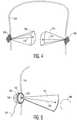
- FIGURE 4illustrates the situation at this point for 3D imaging.
- the transducer arrays 10a,10bare held against the sides of the skull 100 and are imaging 3D image fields 102,104 inside the cranium.
- the userwill see one or both of the 3D image fields 102,104 on the display of the ultrasound system in either a multiplanar or volume rendered 3D projection.
- the usercan manipulate the kinetic parallax control to observe the volume rendered 3D image from different orientations.
- the usercan adjust the relative opacity of the tissue and flow components of the 3D image to better visualize the vascular structure inside the brain tissue as described in US Pat. 5,720,291 (Schwartz ) or can turn off the B mode (tissue) portion of the display entirely and just visualize the flow of the vascular structure inside the 3D image field 102,104.
- a microbubble contrast agentis introduced into the patient's bloodstream at step 66.
- the microbubbles in the bloodstreamwill be pumped through the carotid arteries and into the cranial vascular system and appear in the image.
- the clinician useris now able to begin a diagnostic search for blood clots occluding blood vessels in the brain, looking for branches of the vasculature which terminate or are only dimly lighted by echo returns from microbubbles due to a partial occlusion.
- the clinicianis also able to compare the relative symmetry of the two displayed regions, looking for signs of asymmetry.
- the cliniciancan steer the image field to other regions of the anatomy as indicated by step 68.
- Steering the image fieldcan be done mechanically by physically adjusting the position of a transducer array to aim its image field through different anatomy of the brain.
- the clinicianis able to adjust the steering of the beams from the transducer array with a control on the user interface. By adjusting this control (the Beam Steer control line to the transmit controller 18), the clinician is able to electronically steer the image field around inside the skull without disturbing the acoustic coupling of the array against the head of the patient.
- the cliniciancan look for obstructions of the blood flow in the real time images on the display, or can capture (freeze) an image or map of the cranial vasculature as indicated in step 70.
- the imagecan undergo enhanced processing (e . g ., compounding, signal averaging) to improve the resolution or scale of the image and can be manipulated on the screen and examined carefully at different points and from different views in a precise search for blood vessel occlusions. In this way the clinician can diagnose for stenoses as indicated at step 72.
- the cliniciancan steer the image field to another region of the cranium and examine the vascular map of another image field.
- the cliniciancan use the Doppler data of the vascular map or the spectral Doppler function of the ultrasound system to take flow velocity measurements at specific points in the cranial vasculature, then use the report generation capabilities of the ultrasound system to record the measurements and prepare a report of his diagnosis.
- FIGURE 6aillustrates a vascular network 300 of blood vessels.
- the vascular network 300may be displayed in two dimensions, three dimensions, and by various Doppler techniques such as colorflow (velocity) Doppler or power (intensity) Doppler. In the absence of stenoses the flow network will appear continuous and with velocities and intensities proportionate to vessel size.
- the cliniciancan diagnose a stenosis, then direct a therapeutic beam 110 to the suspected location of the obstruction of the vessel as shown in FIGURE 6d .
- therapycan be applied by agitating or breaking microbubbles at the site of the stenosis in an effort to dissolve the blood clot.
- the clinicianactivate the "therapy" mode, and a graphic 110,112 appears in the image field 102,104, depicting the vector path of a therapeutic ultrasound beam.
- the therapeutic ultrasound beamis manipulated by a control on the user interface 38 until the vector graphic 110,112 is focused at the site of the blockage, as indicated by step 74.
- the therapeutic beamcan be a tightly focused, convergent beam or a beam with a relatively long focal length known as a pencil beam.
- the energy produced for the therapeutic beamcan be in excess of the ultrasound levels permitted for diagnostic ultrasound, in which case the microbubbles at the site of the blood clot will be sharply broken.
- the energy of the resulting microbubble ruptureswill strongly agitate the blood clot, tending to break up the clot and dissolve it in the bloodstream.
- insonification of the microbubbles at diagnostic energy levelsmay be sufficient to dissolve the clot.
- the microbubblesmay be vibrated and oscillated, and the energy from such extended oscillation prior to dissolution of the microbubbles can be sufficient to break up the clot, as indicated at step 76.
- flash transmissionA particularly effective way to insonify the microbubbles is known as "flash" transmission.
- insonificationis halted to allow the flow of blood to deliver a substantial volume of microbubbles to the site of the blockage.
- a rapid series of high MI pulsesare transmitted to rapidly and energetically rupture the microbubbles, which releases energy at the site of the blockage.
- the gas from the ruptured microbubblesdissolves in the bloodstream.
- Another pause periodcommences to allow the buildup of a fresh supply of microbubbles and the process continues. See US Pats. 5,560,364 (Porter) and 5,685,310 (Porter).
- the flash techniquewas improved with the discovery that imaging can be performed at low MI levels as the microbubbles accumulate, enabling the clinician to visually monitor the buildup of microbubbles and determine the optimal time to administer the high MI flash. See US Pat. 6,171,246 (Averkiou et al. )
- the flash pulsesare delivered within the MI (instantaneous pressure) limits of diagnostic ultrasound.
- MIinstantaneous pressure
- Another energy limit parameter for ultrasoundis the spatial peak temporal average (SPTA), which is a measure of the average energy delivered over time and is related to temperature rise.
- SPTAspatial peak temporal average
- the high MI pulsesmay be delivered for 200ms, after which high MI pulses are inhibited for the following 800msec.
- the duty cycle of the high MI pulse delivery periodis thus only 20%. Needless high MI pulses are inhibited and the time averaged energy delivered over the one second interval is within the temporal average limits of the SPTA parameter.
- new microbubblesare allowed to reinfuse the blood clot site as soon as the high MI transmission has ceased.
- longer pulse lengthsmay be employed during the high MI portion of the duty cycle, which have been found to be very effective for microbubble disruption.
- the type of stroke suffered by a patientcan be either hemorrhagic stroke or ischemic stroke.
- Hemorrhagic strokewhich may for instance be caused by a ruptured aneurism, results in blood flow outside of blood vessels and will not be improved by treatment with microbubbles and ultrasound.
- a hemorrhagic conditionis often worsened by the application of tPA.
- Ischemic stroke caused by a stenosissuch as a blood clot is the type of stroke that an embodiment of the present invention is designed to treat. Accordingly it is desirable to initially determine whether the stroke condition is hemorrhagic or ischemic.
- a blood poolwill appear black in the standard ultrasound image since blood is not a strong reflector of ultrasonic waves.
- the blood poolmay also exhibit a lower rate of flow (Doppler velocity) than the flow of blood in a containing blood vessel.
- Doppler velocityrate of flow
- the perfusion of the contrast agent into the microvasculature of surrounding tissuecan create a slight halo effect of brighter contrast about the darkened blood pool in an ultrasound image. It is characteristics such as these which can be used to identify whether the stroke is hemorrhagic or ischemic in origin.
- each image field 102, 104is seen to extend almost halfway across the cranium, which is a balance between the size of the image field and the acoustic penetration and attenuation which may be expected through the bone at the acoustic window.
- low attenuation effectsmay enable an image field to extend fully across the cranium, allowing the clinician to examine the vascular structure near the skull bone on the opposite side of the cranium.
- the vasculature across the full craniummay be effectively examined. It is possible to acquire extended image fields which cover the same central region of the cranium but image from opposite sides of the head.
- the therapeutic beamcan also be transmitted from both sides of the head, enabling breakup of a clot at both sides of the clot.
- through-transmission imagingcan be performed by transmitting ultrasound from one transducer array and receiving the remaining unabsorbed ultrasonic energy at the other transducer array, which may reveal yet other characteristics of the brain tissue.
- FIGURE 5illustrates a two dimensional imaging example.
- the transducer array 122is a one dimensional array which performed 2D imaging.
- the arrayis configured as a circular phased array transducer as described in US Pat. 5,226,422 .
- This transducer arraylike the other arrays described herein, is covered with a lens 124 which electrically insulates the patient from the transducer array and in the case of a one dimensional array may also provide focusing in the elevation (out-of-plane) dimension.
- the transducer array 122is backed with acoustic damping material 126 which attenuates acoustic waves emanating from the back of the array to prevent their reflection back into the transducer elements.
- the device 130may be a simple knob or tab which may be grasped by the clinician to manually rotate the circular array transducer in its rotatable transducer mount (not shown).
- the device 130may also be a motor which is energized through a conductor 132 to mechanically rotate the transducer as discussed in US Pat. 5,181,514 (Solomon et al. ) Rotating the one dimensional array transducer 122 as indicated by arrow 144 will cause its image plane 140 to pivot around its central axis, enabling the repositioning of the image plane for full examination of the vasculature in front of the transducer array.
- the planes acquired during at least a 180o rotation of the arraywill occupy a conical volume in front of the transducer array, which may be rendered into a 3D image of that volumetric region.
- Other planes outside this volumetric regionmay be imaged by repositioning, rocking or tilting the transducer array in its headset in relation to the skull 100.
- the therapeutic beam vector graphic 142can be steered by the clinician to aim the beam at the stenosis and therapeutic pulses applied to disrupt the microbubbles at the site of the stenosis.
- An embodiment of the inventionmay be used for the monitoring of stroke victims for recurrent events.
- the transducer arrays 10a,10b, microbeamformers 12a,12b, and multiplexer 14can be efficiently packaged in a flip-chip configuration as part of the headset. These components can be battery powered and the output of the multiplexer connected to an r.f transmitter.
- a fixed image field 102,104is continually imaged as shown in FIGURE 4 ; it is not necessary to be able to steer or reposition the image field in this embodiment.
- the image data produced by the microbeamformers 12a,12bis wirelessly transmitted to a base unit as described in US Pat. 6,113,547 (Catallo et al. ) At the base station additional beamforming can be performed if necessary as well as the image processing and display functions of the system of FIGURE 1 .
- a wireless connectionmay not be necessary and a wired connection to the base station may be employed.
- the wireless connectionis also useful when the headset is being applied by individuals having minimal experience with the device. For example, a first responder may be unsure that the headset is applied properly and is acquiring a satisfactory image data set of the patient's vasculature. In that case the images can be transmitted to a base station, hospital or other location where experienced personnel can view the images in real time and talk the first responder through a successful application of the headset on the patient.
- image displayis not necessary for the monitoring application.
- successive images of the vasculatureare formed at the base station they are stored in an image store 52, and temporally different images are compared to detect changes in flow of the vasculature by operation of flow change detector 50.
- the flow change detectoroperates by comparing the identical nature of the temporally different images, similar to the image data correlation techniques used to identify motion by image processing as described in US Pat. 6,442,289 (Olsson et al.
- the flow change detector 50will continue its monitoring of the vasculature with no change.
- the vasculaturemay appear as the vascular network 300 of FIGURE 6a for an extended period, and suddenly a section of the flow may cease to be detected as illustrated by the absence of vessels 302 in FIGURE 6c .
- an alarmis activated such as an audible alarm 42 at a nurse's station. Medical assistance can then be brought immediately to the patient.
- the images stored in the image store at the time of the detected flow changecan be examined by medical personnel to discern exactly where in the vasculature the detected obstruction occurred. Therapy can then be directed specifically to the site of the obstruction without the need to closely examine a series of vascular maps.
- image acquisitiondoes not have to be performed at the high rates necessary for real time imaging.
- a new imagecould be acquired every second, for example, or at greater intervals between image acquisitions.
- the lower acquisition rateis helpful for conserving battery power in an ambulatory implementation with an r.f. link.
- the lower image ratealso permits images from multiple patients to be processed in a time-interleaved manner by the same system, which is useful for a nurse's station which needs to monitor multiple patients.
- the headsetmay move relative to the head of the patient, causing a difference between successive images from a transducer 10a, 10b which has moved. Such movement can also cause a specific anatomical region being monitored to move outside of the image field of the transducer array 10a or 10b.
- the flow change detector 50can be designed to be immune to such global changes and look only for localized changes in flow, it may be desirable to alert medical personnel to readjust the headset or to reacquire target anatomy in the image field. This is done in the embodiment of FIGURE 1 by means of an image field controller 54, which performs image analysis of temporally different images to detect changes in global alignment of the image data.
- the successive images of each transducer arraywill be the same and the image data of the images will exhibit a high degree of correlation.
- the image analysis techniques used to measure image alignment in US Pats. 5,556,674 (Weng ), 6,572,549 (Jong et al. ) or 6,589,176 (Jago et al. ) and othersmay be used to perform the image comparison, for instance. Movement of the headset will result in a global change in correlation, which can alert medical personnel to adjust the headset.
- a local change in correlationmay be a localized flow change that should be detected by the flow change detector 50 or the local decorrelation can be used to alert medical personnel to check the patient's condition.
- Another possibilityis to use the global correlation vector as an indication of image-to-image motion.
- the motional changeis then used by the transmit controller 18 to adjust the steering of beams of the image field 102, 104, 140 to relocate the anatomy in the same position in the newly acquired image field, as in the manner of image stabilization discussed in the aforementioned US Pat. 6,589,176 .
- Thiswill enable the anatomy initially monitored by the system to remain in view and in the image data set despite small changes in the headset positioning. If the target anatomy moves beyond the range of beam steering reacquisition, an alert can be issued for medical personnel to reposition the headset.
- Such resteering correction in the presence of motioncan similarly be used to keep the therapeutic pencil beam 110, 112 constantly directed at a targeted blood clot being treated.
- a typical sequence for a monitoring implementationis illustrated by the flowchart of FIGURE 7 .
- the headset with the array transducersis put on the patient at step 60 and images are initially displayed and reviewed until the headset is adjusted so that flow is observed in the images in step 62.
- image displayis no longer necessary and the headset is tightened in place on the patient at step 64.
- Periodically image datais acquired from the image field of the arrays and transmitted to the monitoring unit at step 80.
- the image datamay be further processed as desired at step 82, then the new image is compared to one or more previously acquired images at step 84. If the flow characteristics of the images are unchanged, periodic transmission, reception, and comparison of image data continues. But if the new image is different in a predetermined flow characteristic, the flow change is detected at 86 and an alert issued at 88 for medical attention.
- monitoring implementationcan be performed with 2D (planar) imaging, it is preferred that 3D imaging be used so that a larger volumetric region can be monitored.
- Monitoringcan be performed with only one transducer array, but a greater number of arrays likewise provides monitoring of a larger region of the cranium.
Landscapes
- Health & Medical Sciences (AREA)
- Life Sciences & Earth Sciences (AREA)
- Engineering & Computer Science (AREA)
- Veterinary Medicine (AREA)
- Public Health (AREA)
- General Health & Medical Sciences (AREA)
- Animal Behavior & Ethology (AREA)
- Biomedical Technology (AREA)
- Surgery (AREA)
- Molecular Biology (AREA)
- Heart & Thoracic Surgery (AREA)
- Medical Informatics (AREA)
- Pathology (AREA)
- Biophysics (AREA)
- Physics & Mathematics (AREA)
- Nuclear Medicine, Radiotherapy & Molecular Imaging (AREA)
- Radiology & Medical Imaging (AREA)
- Hematology (AREA)
- Vascular Medicine (AREA)
- Neurology (AREA)
- Cardiology (AREA)
- Physiology (AREA)
- Mechanical Engineering (AREA)
- Orthopedic Medicine & Surgery (AREA)
- Ultra Sonic Daignosis Equipment (AREA)
- Surgical Instruments (AREA)
Description
- This invention relates to medical diagnostic ultrasound systems and, in particular, to ultrasound systems which perform imaging and therapy for stroke victims.
- Ischemic stroke is one of the most debilitating disorders known to medicine. The blockage of the flow of blood to the brain can rapidly result in paralysis or death. Attempts to achieve recanalization through thrombolytic drug therapy such as treatment with tissue plasminogen activator (tPA) has been reported to cause symptomatic intracerebral hemorrhage in a number of cases. Advances in the diagnosis and treatment of this crippling affliction are the subject of continuing medical research.
- Transcranial Doppler ultrasound has been developed for use in monitoring and diagnosing stroke. A headset device manufactured by Spencer Technologies of Seattle, Washington, USA holds two transducers against the side of the skull, one on each temporal bone just in front of the ear. The transducers transmit ultrasonic waves through the temporal bone and the returning echo signals are Doppler processed and the phase shift information reproduced at audible frequencies. The audible Doppler identifies the presence or absence of blood flow inside the cranium as the clinician listens for characteristic sounds of blood flow velocities of specific arteries. The technique can also be augmented with a spectral Doppler display of the phase shift information, providing information on flow velocities inside the cranium. However, since there is no information concerning the anatomy inside the skull, the clinician must attempt to make a diagnosis on the basis of this limited information.
- A system according to the preamble of
claim 1 is known fromEP 1 591 073 A1 - Recently Dr. Andrei Alexandrov of the University of Texas Medical School at Houston, Texas found that the application of ultrasound during tPA treatment improved the efficacy of tPA for stroke treatment. Dr. Alexandrov observed that the micro-vibrations of the ultrasonic waves work on the surface of the blood clot to open up a larger surface that the tPA can then bind to and penetrate. Dr. Alexandrov is now leading a research team which is investigating the added efficacy of adding ultrasonic contrast agent microbubbles to the tPA or using microbubbles and ultrasound alone to dissolve blood clots. It is also contemplated that microbubbles may be targeted to components in the blood clot such as fibrin and stick to the clot, increasing the concentration and effectiveness of the treatment. Targeted nanoparticles are another possibility for this procedure. It is thus believed by many that ultrasound together with thrombolytic drugs, microbubbles, or both can lead to significant improvement in stroke treatment.
- In accordance with the principles of the present invention, a diagnostic ultrasound system is described which enables a clinician to transcranially visualize a region of the cerebral vasculature where blood clots may be present. A corresponding method is described, too, however, with no claim being directed at such method. Either two dimensional or three dimensional imaging may be employed. The imaging of the vasculature is preferably enhanced by the administration of microbubbles. If the flow conditions of the vasculature indicate the presence of a partial or complete occlusion, a focused or pencil beam is directed to the location of the blockage to break up the clot by the vibrations and/or rupturing of the microbubbles. In some instances the ruptured microbubbles may also release an encapsulated thrombolytic drug. In accordance with a further aspect of the present invention, the cranial vasculature may be monitored by ultrasonic imaging for changes which are indicative of the recurrence of an occlusion, and medical aid alerted to the condition.
- In the drawings:
FIGURE 1 illustrates in block diagram form an ultrasonic diagnostic imaging system constructed in accordance with the principles of the present invention.FIGURES 2a and 2b illustrate a safety helmet liner suitable for use in a transcranial imaging transducer headset.FIGURE 3 illustrates a procedure for ultrasonically imaging the cranial vasculature and dissolving blood clots.FIGURE 4 illustrates three dimensional transcranial imaging.FIGURE 5 illustrates two dimensional transcranial imaging.FIGURES 6a-6d illustrate treatment of a cranial occlusion.FIGURE 7 illustrates a procedure for ultrasonically monitoring for cranial occlusions.- Referring first to
FIGURE 1 , an ultrasound system constructed in accordance with the principles of the present invention is shown in block diagram form. Twotransducer arrays microbeamformers 5,997,479 (Savord et al. ),6,013,032 (Savord ), and6,623,432 (Powers et al. ) Signals are routed to and from the microbeamformers by amultiplexer 14 by time-interleaving signals. The multiplexer is coupled to a transmit/receive (T/R)switch 16 which switches between transmission and reception and protects themain beamformer 20 from high energy transmit signals. The transmission of ultrasonic beams from thetransducer arrays microbeamformers transmit controller 18 coupled to the T/R switch, which received input from the user's operation of the user interface orcontrol panel 38. - The partially beamformed signals produced by the
microbeamformers main beamformer 20 where partially beamformed signals from the individual patches of elements are combined into a fully beamformed signal. For example, themain beamformer 20 may have 128 channels, each of which receives a partially beamformed signal from a patch of 12 transducer elements. In this way the signals received by over 1500 transducer elements of a two dimensional array can contribute efficiently to a single beamformed signal. - The beamformed signals are coupled to a fundamental/
harmonic signal separator 22. Theseparator 22 acts to separate linear and nonlinear signals so as to enable the identification of the strongly nonlinear echo signals returned from microbubbles. Theseparator 22 may operate in a variety of ways such as by bandpass filtering the received signals in fundamental frequency and harmonic frequency bands, or by a process known as pulse inversion harmonic separation. A suitable fundamental/harmonic signal separator is shown and described in international patent publicationWO 2005/074805 (Bruce et al. ) The separated signals are coupled to asignal processor 24 where they may undergo additional enhancement such as speckle removal, signal compounding, and noise elimination. - The processed signals are coupled to a
B mode processor 26 and a Dopplerprocessor 28. TheB mode processor 26 employs amplitude detection for the imaging of structures in the body such as muscle, tissue, and blood cells. B mode images of structure of the body may be formed in either the harmonic mode or the fundamental mode. Tissues in the body and microbubbles both return both types of signals and the harmonic returns of microbubbles enable microbubbles to be clearly segmented in an image in most applications. The Doppler processor processes temporally distinct signals from tissue and blood flow for the detection of motion of substances in the image field including microbubbles. The structural and motion signals produced by these processors are coupled to ascan converter 32 and avolume renderer 34, which produce image data of tissue structure, flow, or a combined image of both characteristics. The scan converter will convert echo signals with polar coordinates into image signals of the desired image format such as a sector image in Cartesian coordinates. Thevolume renderer 34 will convert a 3D data set into a projected 3D image as viewed from a given reference point as described inUS Pat. 6,530,885 (Entrekin et al. ) As described therein, when the reference point of the rendering is changed the 3D image can appear to rotate in what is known as kinetic parallax. This image manipulation is controlled by the user as indicated by the Display Control line between theuser interface 38 and thevolume renderer 34. Also described is the representation of a 3D volume by planar images of different image planes, a technique known as multiplanar reformatting. Thevolume renderer 34 can operate on image data in either rectilinear or polar coordinates as described inUS Pat. 6,723,050 (Dow et al. ) The 2D or 3D images are coupled from the scan converter and volume renderer to animage processor 30 for further enhancement, buffering and temporary storage for display on animage display 40. - A
graphics processor 36 is also coupled to theimage processor 30 which generates graphic overlays for displaying with the ultrasound images. These graphic overlays can contain standard identifying information such as patient name, date and time of the image, imaging parameters, and the like, and can also produce a graphic overlay of a beam vector steered by the user as described below. For this purpose the graphics processor received input from theuser interface 38. The user interface is also coupled to the transmitcontroller 18 to control the generation of ultrasound signals from thetransducer arrays - The
transducer arrays FIGURE 2a shows aconventional safety helmet 200 which is adjustably held on the wearer's head by ahelmet liner 202 shown in the view ofFIGURE 2b . The helmet liner wraps securely about the circumference of the wearer's head. Transducer arrays positioned inside the helmet liner on either side as indicated by the locations of circles 204,206 will be held securely against the skin of the temporal bones of the wearer, enabling thehelmet liner 202 to function as a transcranial ultrasound headset. The helmet liner headset is adjustably secured in place by anadjustment knob 208. An occipital transducer would be positioned at or below the location ofadjustment knob 208. The headset has one ormore straps 210 which pass over the top of the head for adjustment of the vertical position of the headset. These straps and other adjustable members of the headset can be elastic or adjustable through other means such as buckles or Velcro®. When properly adjusted the headset will hold the acoustic transducer arrays securely in good acoustic contact on the temples of the patient. Acoustic coupling may be aided by applying an acoustic coupling gel between the transducer and the skin. - A procedure which uses the ultrasound system and transcranial ultrasound headset just described is illustrated by the flowchart of
FIGURE 3 . Instep 60 the headset is put on the patient with the transducer arrays in acoustic contact with the skin of the patient. The system is activated to image inside the cranium and instep 62 the headset is adjusted until flow inside the cranium can be seen in the ultrasound image of one or (when displayed in duplex) both of the transducer arrays. The colorflow imaging mode of the system is preferably used at this time to produce a two or three dimensional image of the bloodflow inside the cranium. If the cranial flow can be seen in colorflow, the other steps of this procedure can be expected to proceed as desired. When the flow is seen in the ultrasound images the headset is tightened instep 64 to secure the transducer array in their imaging positions.FIGURE 4 illustrates the situation at this point for 3D imaging. In this illustration thetransducer arrays skull 100 and are imaging 3D image fields 102,104 inside the cranium. The user will see one or both of the 3D image fields 102,104 on the display of the ultrasound system in either a multiplanar or volume rendered 3D projection. The user can manipulate the kinetic parallax control to observe the volume rendered 3D image from different orientations. The user can adjust the relative opacity of the tissue and flow components of the 3D image to better visualize the vascular structure inside the brain tissue as described inUS Pat. 5,720,291 (Schwartz ) or can turn off the B mode (tissue) portion of the display entirely and just visualize the flow of the vascular structure inside the 3D image field 102,104. - When the cranium is being imaged successfully a microbubble contrast agent is introduced into the patient's bloodstream at
step 66. In a short time the microbubbles in the bloodstream will be pumped through the carotid arteries and into the cranial vascular system and appear in the image. The clinician user is now able to begin a diagnostic search for blood clots occluding blood vessels in the brain, looking for branches of the vasculature which terminate or are only dimly lighted by echo returns from microbubbles due to a partial occlusion. When a dual display from both transducer arrays is present the clinician is also able to compare the relative symmetry of the two displayed regions, looking for signs of asymmetry. If the clinician finds no signs of occlusion in the vasculature presently being viewed by the image fields 102,104, the clinician can steer the image field to other regions of the anatomy as indicated bystep 68. Steering the image field can be done mechanically by physically adjusting the position of a transducer array to aim its image field through different anatomy of the brain. Preferably, the clinician is able to adjust the steering of the beams from the transducer array with a control on the user interface. By adjusting this control (the Beam Steer control line to the transmit controller 18), the clinician is able to electronically steer the image field around inside the skull without disturbing the acoustic coupling of the array against the head of the patient. - At each position of the image field 102,104 the clinician can look for obstructions of the blood flow in the real time images on the display, or can capture (freeze) an image or map of the cranial vasculature as indicated in
step 70. When the vascular map is acquired and held statically, the image can undergo enhanced processing (e.g., compounding, signal averaging) to improve the resolution or scale of the image and can be manipulated on the screen and examined carefully at different points and from different views in a precise search for blood vessel occlusions. In this way the clinician can diagnose for stenoses as indicated atstep 72. If the clinician examines a vascular map and finds no evidence of obstruction in the blood flow paths, the clinician can steer the image field to another region of the cranium and examine the vascular map of another image field. The clinician can use the Doppler data of the vascular map or the spectral Doppler function of the ultrasound system to take flow velocity measurements at specific points in the cranial vasculature, then use the report generation capabilities of the ultrasound system to record the measurements and prepare a report of his diagnosis. - Examples of vascular maps are shown in
FIGURES 6a-6c. FIGURE 6a illustrates avascular network 300 of blood vessels. When only flow imaging is performed and the flow image is displayed in the absence of any surrounding B mode tissue structure, as described inUS Pat. 5,474,073 (Schwartz et al. ), only the flow of the vasculature is shown without any obscuring surrounding structure asFIGURE 6a illustrates. Thevascular network 300 may be displayed in two dimensions, three dimensions, and by various Doppler techniques such as colorflow (velocity) Doppler or power (intensity) Doppler. In the absence of stenoses the flow network will appear continuous and with velocities and intensities proportionate to vessel size. But if abranch 302 of the vascular network is obstructed, the flow will appear different, e.g., higher velocity and/or intensity, and, if completely obstructed, will disappear entirely in the Doppler flow map as shown inFIGURE 6c . By discerning characteristics such as these, the clinician can diagnose a stenosis, then direct atherapeutic beam 110 to the suspected location of the obstruction of the vessel as shown inFIGURE 6d . - If the clinician discovers a stenosis, therapy can be applied by agitating or breaking microbubbles at the site of the stenosis in an effort to dissolve the blood clot. The clinician activate the "therapy" mode, and a graphic 110,112 appears in the image field 102,104, depicting the vector path of a therapeutic ultrasound beam. The therapeutic ultrasound beam is manipulated by a control on the
user interface 38 until the vector graphic 110,112 is focused at the site of the blockage, as indicated bystep 74. The therapeutic beam can be a tightly focused, convergent beam or a beam with a relatively long focal length known as a pencil beam. The energy produced for the therapeutic beam can be in excess of the ultrasound levels permitted for diagnostic ultrasound, in which case the microbubbles at the site of the blood clot will be sharply broken. The energy of the resulting microbubble ruptures will strongly agitate the blood clot, tending to break up the clot and dissolve it in the bloodstream. However in some instances insonification of the microbubbles at diagnostic energy levels may be sufficient to dissolve the clot. Rather than breaking in a single event, the microbubbles may be vibrated and oscillated, and the energy from such extended oscillation prior to dissolution of the microbubbles can be sufficient to break up the clot, as indicated atstep 76. - A particularly effective way to insonify the microbubbles is known as "flash" transmission. In flash transmission, insonification is halted to allow the flow of blood to deliver a substantial volume of microbubbles to the site of the blockage. At the end of this pause, a rapid series of high MI pulses are transmitted to rapidly and energetically rupture the microbubbles, which releases energy at the site of the blockage. The gas from the ruptured microbubbles dissolves in the bloodstream. Another pause period commences to allow the buildup of a fresh supply of microbubbles and the process continues. See US Pats. 5,560,364 (Porter) and 5,685,310 (Porter). The flash technique was improved with the discovery that imaging can be performed at low MI levels as the microbubbles accumulate, enabling the clinician to visually monitor the buildup of microbubbles and determine the optimal time to administer the high MI flash. See
US Pat. 6,171,246 (Averkiou et al. ) - It has been found that a low duty cycle flash will create rapid microbubble destruction within the energy limits of diagnostic ultrasound. There is thus no need to expose the patient to possibly harmful therapeutic exposure levels. In this technique, the flash pulses are delivered within the MI (instantaneous pressure) limits of diagnostic ultrasound. Another energy limit parameter for ultrasound is the spatial peak temporal average (SPTA), which is a measure of the average energy delivered over time and is related to temperature rise. It has been discovered that a series of high MI pulses (within diagnostic limits) will cause the targeted microbubbles to break up and dissolve in the bloodstream in 100-300 milliseconds. Thus, continued insonification is of no effect, for virtually no microbubbles remain after this period. In the inventive technique, the high MI pulse period has a duty cycle of 50% or less. For instance, the high MI pulses may be delivered for 200ms, after which high MI pulses are inhibited for the following 800msec. The duty cycle of the high MI pulse delivery period is thus only 20%. Needless high MI pulses are inhibited and the time averaged energy delivered over the one second interval is within the temporal average limits of the SPTA parameter. Furthermore, new microbubbles are allowed to reinfuse the blood clot site as soon as the high MI transmission has ceased. Moreover, longer pulse lengths may be employed during the high MI portion of the duty cycle, which have been found to be very effective for microbubble disruption.
- The type of stroke suffered by a patient can be either hemorrhagic stroke or ischemic stroke. Hemorrhagic stroke, which may for instance be caused by a ruptured aneurism, results in blood flow outside of blood vessels and will not be improved by treatment with microbubbles and ultrasound. Furthermore, a hemorrhagic condition is often worsened by the application of tPA. Ischemic stroke caused by a stenosis such as a blood clot is the type of stroke that an embodiment of the present invention is designed to treat. Accordingly it is desirable to initially determine whether the stroke condition is hemorrhagic or ischemic. One way this may be done is by looking for a blood pool outside the vasculature, which is indicative of a hemorrhagic condition. A blood pool will appear black in the standard ultrasound image since blood is not a strong reflector of ultrasonic waves. The blood pool may also exhibit a lower rate of flow (Doppler velocity) than the flow of blood in a containing blood vessel. After the contrast agent is introduced, the perfusion of the contrast agent into the microvasculature of surrounding tissue can create a slight halo effect of brighter contrast about the darkened blood pool in an ultrasound image. It is characteristics such as these which can be used to identify whether the stroke is hemorrhagic or ischemic in origin.
- In the depiction of
FIGURE 4 , eachimage field FIGURE 5 illustrates a two dimensional imaging example. In this example thetransducer array 122 is a one dimensional array which performed 2D imaging. The array is configured as a circular phased array transducer as described inUS Pat. 5,226,422 . This transducer array, like the other arrays described herein, is covered with alens 124 which electrically insulates the patient from the transducer array and in the case of a one dimensional array may also provide focusing in the elevation (out-of-plane) dimension. Thetransducer array 122 is backed with acoustic dampingmaterial 126 which attenuates acoustic waves emanating from the back of the array to prevent their reflection back into the transducer elements. Behind this transducer stack is adevice 130 for rotating theimage plane 140 of the array. Thedevice 130 may be a simple knob or tab which may be grasped by the clinician to manually rotate the circular array transducer in its rotatable transducer mount (not shown). Thedevice 130 may also be a motor which is energized through aconductor 132 to mechanically rotate the transducer as discussed inUS Pat. 5,181,514 (Solomon et al. ) Rotating the onedimensional array transducer 122 as indicated byarrow 144 will cause itsimage plane 140 to pivot around its central axis, enabling the repositioning of the image plane for full examination of the vasculature in front of the transducer array. As discussed in the '514 patent, the planes acquired during at least a 180o rotation of the array will occupy a conical volume in front of the transducer array, which may be rendered into a 3D image of that volumetric region. Other planes outside this volumetric region may be imaged by repositioning, rocking or tilting the transducer array in its headset in relation to theskull 100. If a stenosis is found in the image of the plane being imaged, the therapeutic beam vector graphic 142 can be steered by the clinician to aim the beam at the stenosis and therapeutic pulses applied to disrupt the microbubbles at the site of the stenosis.- It is common in the case of stroke that the affliction will not manifest itself in a single episode, but in repeated episodes as a blood clot or obstruction in the heart, lungs, or blood vessel breaks up gradually, releasing small clots which successively make their way to the vascular system of the brain over time. Thus, a patient who survives an initial stroke event, may be at risk for other events in the near future. Accordingly, it is desirable to monitor these patients for some time after an initial stroke event so that recurrences can be treated immediately. An embodiment of the invention may be used for the monitoring of stroke victims for recurrent events. The
transducer arrays microbeamformers multiplexer 14 can be efficiently packaged in a flip-chip configuration as part of the headset. These components can be battery powered and the output of the multiplexer connected to an r.f transmitter. A fixed image field 102,104 is continually imaged as shown inFIGURE 4 ; it is not necessary to be able to steer or reposition the image field in this embodiment. The image data produced by themicrobeamformers US Pat. 6,113,547 (Catallo et al. ) At the base station additional beamforming can be performed if necessary as well as the image processing and display functions of the system ofFIGURE 1 . If a patient is not ambulatory a wireless connection may not be necessary and a wired connection to the base station may be employed. The wireless connection is also useful when the headset is being applied by individuals having minimal experience with the device. For example, a first responder may be unsure that the headset is applied properly and is acquiring a satisfactory image data set of the patient's vasculature. In that case the images can be transmitted to a base station, hospital or other location where experienced personnel can view the images in real time and talk the first responder through a successful application of the headset on the patient. - In the present example, image display is not necessary for the monitoring application. As successive images of the vasculature are formed at the base station they are stored in an
image store 52, and temporally different images are compared to detect changes in flow of the vasculature by operation offlow change detector 50. The flow change detector operates by comparing the identical nature of the temporally different images, similar to the image data correlation techniques used to identify motion by image processing as described inUS Pat. 6,442,289 (Olsson et al. ) As long as successive images and images separated by greater time intervals appear substantially the same in their flow characteristics, e.g., there is no localized change in the flow characteristics of a particular section of the vasculature and no section of the vasculature has ceased to return a Doppler signal indicating the continuation of flow, theflow change detector 50 will continue its monitoring of the vasculature with no change. For example, the vasculature may appear as thevascular network 300 ofFIGURE 6a for an extended period, and suddenly a section of the flow may cease to be detected as illustrated by the absence ofvessels 302 inFIGURE 6c . If a flow change such as one of those indicated above is detected by theflow change detector 50, an alarm is activated such as anaudible alarm 42 at a nurse's station. Medical assistance can then be brought immediately to the patient. In addition, the images stored in the image store at the time of the detected flow change can be examined by medical personnel to discern exactly where in the vasculature the detected obstruction occurred. Therapy can then be directed specifically to the site of the obstruction without the need to closely examine a series of vascular maps. - Since this is a monitoring application, image acquisition does not have to be performed at the high rates necessary for real time imaging. A new image could be acquired every second, for example, or at greater intervals between image acquisitions. The lower acquisition rate is helpful for conserving battery power in an ambulatory implementation with an r.f. link. The lower image rate also permits images from multiple patients to be processed in a time-interleaved manner by the same system, which is useful for a nurse's station which needs to monitor multiple patients.
- During long term monitoring or monitoring of ambulatory patients it is possible that the headset may move relative to the head of the patient, causing a difference between successive images from a
transducer transducer array flow change detector 50 can be designed to be immune to such global changes and look only for localized changes in flow, it may be desirable to alert medical personnel to readjust the headset or to reacquire target anatomy in the image field. This is done in the embodiment ofFIGURE 1 by means of animage field controller 54, which performs image analysis of temporally different images to detect changes in global alignment of the image data. If the headset has not moved between successive images, for example, the successive images of each transducer array will be the same and the image data of the images will exhibit a high degree of correlation. The image analysis techniques used to measure image alignment in US Pats.5,556,674 (Weng ),6,572,549 (Jong et al. ) or6,589,176 (Jago et al. ) and others may be used to perform the image comparison, for instance. Movement of the headset will result in a global change in correlation, which can alert medical personnel to adjust the headset. A local change in correlation may be a localized flow change that should be detected by theflow change detector 50 or the local decorrelation can be used to alert medical personnel to check the patient's condition. Another possibility is to use the global correlation vector as an indication of image-to-image motion. The motional change is then used by the transmitcontroller 18 to adjust the steering of beams of theimage field US Pat. 6,589,176 . This will enable the anatomy initially monitored by the system to remain in view and in the image data set despite small changes in the headset positioning. If the target anatomy moves beyond the range of beam steering reacquisition, an alert can be issued for medical personnel to reposition the headset. Such resteering correction in the presence of motion can similarly be used to keep thetherapeutic pencil beam - A typical sequence for a monitoring implementation is illustrated by the flowchart of
FIGURE 7 . The headset with the array transducers is put on the patient atstep 60 and images are initially displayed and reviewed until the headset is adjusted so that flow is observed in the images instep 62. When it is determined that images of cranial flow are being acquired, image display is no longer necessary and the headset is tightened in place on the patient atstep 64. Periodically image data is acquired from the image field of the arrays and transmitted to the monitoring unit atstep 80. At the monitoring unit the image data may be further processed as desired atstep 82, then the new image is compared to one or more previously acquired images atstep 84. If the flow characteristics of the images are unchanged, periodic transmission, reception, and comparison of image data continues. But if the new image is different in a predetermined flow characteristic, the flow change is detected at 86 and an alert issued at 88 for medical attention. - While the monitoring implementation can be performed with 2D (planar) imaging, it is preferred that 3D imaging be used so that a larger volumetric region can be monitored. Monitoring can be performed with only one transducer array, but a greater number of arrays likewise provides monitoring of a larger region of the cranium.
Claims (12)
- A stroke therapy system for treating cranial vascular obstructions comprising:a transducer array headset (200) which maintains an ultrasonic transducer array (10a, 10b, 122) in acoustic contact with the head of a subject;an image processor (26, 28, 30, 32, 34), coupled to the ultrasonic transducer array, which produces images of blood flow in the cranium of the subject in an imaging mode of the ultrasonic transducer array;an image display (40), coupled to the image processor, which produces an image of the cranial vasculature;characterized in that:the ultrasonic transducer array is operable in a therapy mode to direct a therapeutic beam at an obstruction site (302) in the cranium of the subject, said therapeutic beam being capable of breaking up microbubbles, introduced to the subject's bloodstream, at the obstruction site and comprising a series of ultrasonic beam pulses having a duty cycle of 50% or less,wherein, in the therapy mode, the ultrasonic therapeutic beam is iteratively:delivered to the obstruction site for a period of 100-300 milliseconds, to thereby break up substantially all of the microbubbles at the obstruction site; andsubsequently inhibited, to allow new microbubbles to reinfuse the obstruction site.
- The stroke therapy system of Claim 1, wherein the system further comprises a user interface (38) comprising a control adapted to, in the therapy mode, be manipulated by a user to steer a therapeutic beam vector graphic (110, 112, 142) on the image display (40) to direct the therapeutic beam at the obstruction site (302).
- The stroke therapy system of Claim 1, wherein the therapeutic beam is a pencil beam.
- The stroke therapy system of Claim 1, wherein the image processor comprises a Doppler processor, wherein the Doppler processor (28) produces at least one of velocity Doppler images or power Doppler images.
- The stroke therapy system of Claim 1, wherein the transducer array headset maintains a first ultrasonic transducer array (10a) in acoustic contact with one side (204) of the head (100); and
further comprising a second transducer array (10b) maintained in acoustic contact with the other side (206) of the head by the headset (200). - The stroke therapy system of Claim 1, wherein the system further comprises a transmitter, coupled to the transducer array, which acts to cause the ultrasonic transducer array to transmit said therapeutic beam, wherein imaging and delivery of the therapeutic beam are done by the ultrasonic transducer array.
- The stroke therapy system of Claim 6, wherein the transmitter further acts to cause the ultrasonic transducer array to transmit beams for at least one of Doppler or B mode imaging.
- The stroke therapy system of Claim 6, wherein the transmitter further acts to transmit beams for imaging over an image field exhibiting a given lateral dimension in the cranium, wherein the therapeutic beam exhibits a lateral dimension which is less than the given lateral dimension.
- The stroke therapy system of Claim 6, wherein the transmitter further acts to transmit image beams over an image field occupying a given spatial region in the cranium, wherein the therapeutic beam is transmitted over a portion of the given spatial region.
- The stroke therapy system of Claim 9, wherein the ultrasonic transducer array comprises a two dimensional array of transducer elements, wherein the given spatial region is a volumetric region.
- The stroke therapy system of Claim 10, wherein the two dimensional array is maintained in acoustic contact with one side of the head;
the stroke therapy system further comprising a second two dimensional array maintained in acoustic contact by the headset with the other side of the head. - The stroke therapy system of Claim 11, wherein:the first two dimensional array scans imaging beams over a majority of the cranial distance between the left side of the head and the center of the cranium; andthe second two dimensional array scans imaging beams over a majority of the cranial distance between the right side of the head and the center of the cranium.
Applications Claiming Priority (2)
| Application Number | Priority Date | Filing Date | Title |
|---|---|---|---|
| US82210606P | 2006-08-11 | 2006-08-11 | |
| PCT/IB2007/053073WO2008017997A2 (en) | 2006-08-11 | 2007-08-03 | Ultrasound system for cerebral blood flow imaging and microbubble-enhanced blood clot lysis |
Publications (2)
| Publication Number | Publication Date |
|---|---|
| EP2051777A2 EP2051777A2 (en) | 2009-04-29 |
| EP2051777B1true EP2051777B1 (en) | 2019-01-16 |
Family
ID=39030023
Family Applications (1)
| Application Number | Title | Priority Date | Filing Date |
|---|---|---|---|
| EP07825989.2ANot-in-forceEP2051777B1 (en) | 2006-08-11 | 2007-08-03 | Ultrasound system for cerebral blood flow imaging and microbubble-enhanced blood clot lysis |
Country Status (5)
| Country | Link |
|---|---|
| US (2) | US9630028B2 (en) |
| EP (1) | EP2051777B1 (en) |
| JP (2) | JP5450065B2 (en) |
| CN (1) | CN101500650B (en) |
| WO (1) | WO2008017997A2 (en) |
Families Citing this family (66)
| Publication number | Priority date | Publication date | Assignee | Title |
|---|---|---|---|---|
| EP1647232B1 (en) | 2001-12-03 | 2011-08-17 | Ekos Corporation | Catheter with multiple ultrasound radiating members |
| EP2051777B1 (en)* | 2006-08-11 | 2019-01-16 | Koninklijke Philips N.V. | Ultrasound system for cerebral blood flow imaging and microbubble-enhanced blood clot lysis |
| US20100041989A1 (en)* | 2006-09-29 | 2010-02-18 | The Trustees Of The University Of Pennsylvania | Use of ultrasound as an antivascular agent |
| US10182833B2 (en) | 2007-01-08 | 2019-01-22 | Ekos Corporation | Power parameters for ultrasonic catheter |
| EP2170181B1 (en) | 2007-06-22 | 2014-04-16 | Ekos Corporation | Method and apparatus for treatment of intracranial hemorrhages |
| US20100210940A1 (en)* | 2008-11-14 | 2010-08-19 | Hoag Memorial Hospital Presbyterian | CT-Guided Focused Ultrasound for Stroke Treatment |
| WO2010103469A1 (en) | 2009-03-12 | 2010-09-16 | Koninklijke Philips Electronics, N.V. | Sonolysis of blood clots using low power, coded excitation pulses |
| WO2010118307A1 (en)* | 2009-04-09 | 2010-10-14 | The Trustees Of The University Of Pennsylvania | Methods and systems for image-guided treatment of blood vessels |
| US20120165670A1 (en)* | 2009-09-03 | 2012-06-28 | Koninklijke Philips Electronics N.V. | Contralateral array based correction of transcranial ultrasound aberration |
| RU2565507C2 (en)* | 2009-11-25 | 2015-10-20 | Конинклейке Филипс Электроникс Н.В. | System and method for improving image quality |
| JP6291253B2 (en) | 2010-08-27 | 2018-03-14 | イーコス・コーポレイシヨン | Ultrasound catheter |
| CN101919710A (en)* | 2010-09-17 | 2010-12-22 | 天津大学 | Medical Ultrasound Imager |
| WO2012042423A1 (en) | 2010-09-30 | 2012-04-05 | Koninklijke Philips Electronics N.V. | Monitoring and control of microbubble cavitation in therapeutic ultrasound |
| JP6099865B2 (en)* | 2011-01-11 | 2017-03-22 | 東芝メディカルシステムズ株式会社 | Diagnostic imaging equipment |
| HK1205025A1 (en)* | 2012-05-11 | 2015-12-11 | 加利福尼亚大学董事会 | Portable device to initiate and monitor treatment of stroke victims in the field |
| US10413278B2 (en) | 2012-06-28 | 2019-09-17 | University of Pittsburgh—of the Commonwealth System of Higher Education | Methods and devices for ultrasound contrast-assisted therapy |
| BR112015008469A2 (en) | 2012-10-19 | 2017-07-04 | Koninklijke Philips Nv | head frame and imaging equipment |
| US10420532B2 (en) | 2013-01-23 | 2019-09-24 | Brainlab Ag | Method and apparatus for calculating the contact position of an ultrasound probe on a head |
| WO2014159274A1 (en) | 2013-03-14 | 2014-10-02 | Ekos Corporation | Method and apparatus for drug delivery to a target site |
| WO2015073903A1 (en)* | 2013-11-15 | 2015-05-21 | Neural Analytics Inc. | Monitoring structural features of cerebral blood flow velocity for diagnosis of neurological conditions |
| WO2014207665A2 (en) | 2013-06-28 | 2014-12-31 | Koninklijke Philips N.V. | Transducer placement and registration for image-guided sonothrombolysis |
| CA2917095C (en) | 2013-07-03 | 2021-11-02 | Bracco Suisse S.A. | Devices and methods for the ultrasound treatment of ischemic stroke |
| US20160278736A1 (en)* | 2013-11-15 | 2016-09-29 | Neural Analytics Inc. | Monitoring structural features of cerebral blood flow velocity for diagnosis of neurological conditions |
| WO2015075603A1 (en) | 2013-11-21 | 2015-05-28 | Koninklijke Philips N.V. | Ultrasound headset |
| WO2015092604A1 (en) | 2013-12-18 | 2015-06-25 | Koninklijke Philips N.V. | System and method for ultrasound and computed tomography image registration for sonothrombolysis treatment |
| US20150374334A1 (en)* | 2014-01-08 | 2015-12-31 | QT Ultrasound LLC | Quantitative transmission ultrasound imaging of dense anatomical structures |
| WO2016075586A1 (en)* | 2014-11-14 | 2016-05-19 | Koninklijke Philips N.V. | Ultrasound device for sonothrombolysis therapy |
| CN106999149B (en)* | 2014-11-25 | 2020-09-29 | 皇家飞利浦有限公司 | Multi-sensor ultrasound probe and related methods |
| WO2016092414A1 (en) | 2014-12-11 | 2016-06-16 | Koninklijke Philips N.V. | Microbubble signal based temporal-bone thickness compensation for sonothrombolysis |
| WO2016097867A2 (en) | 2014-12-19 | 2016-06-23 | Université Pierre Et Marie Curie (Paris 6) | Implantable ultrasound generating treating device for brain treatment, apparatus comprising such device and method implementing such device |
| CN107530555A (en) | 2015-03-30 | 2018-01-02 | 皇家飞利浦有限公司 | The ultrasound transducer array disposed and monitored for ultrasound thrombolysis |
| CN107708581B (en) | 2015-06-10 | 2021-11-19 | Ekos公司 | Ultrasonic wave guide tube |
| CN104887185A (en)* | 2015-06-12 | 2015-09-09 | 冯明臣 | Treatment device for severe brain patients |
| CN107635472A (en) | 2015-06-19 | 2018-01-26 | 神经系统分析公司 | Transcranial doppler detector |
| EP3316927B1 (en) | 2015-06-30 | 2020-03-25 | Koninklijke Philips N.V. | Infusion system and method for sonothrombolysis stroke treatment |
| CN104984701B (en)* | 2015-07-13 | 2017-06-27 | 中国科学院声学研究所 | A kind of cavitation cloud microbubble preparation device and method thereof |
| CN105193449A (en)* | 2015-10-14 | 2015-12-30 | 苏州斯科特医学影像科技有限公司 | Application of three-dimensional ultrasound in hystero-salpingography |
| CN105286915A (en)* | 2015-10-14 | 2016-02-03 | 苏州斯科特医学影像科技有限公司 | Head temporal bone imaging method in combination with phased array probe |
| CN105147331A (en)* | 2015-10-14 | 2015-12-16 | 苏州斯科特医学影像科技有限公司 | Application of three-dimensional ultrasound in artificial abortion |
| WO2017120361A1 (en) | 2016-01-05 | 2017-07-13 | Neural Analytics, Inc. | Integrated probe structure |
| CN108778140A (en) | 2016-01-05 | 2018-11-09 | 神经系统分析公司 | Systems and methods for determining clinical indications |
| US11589836B2 (en)* | 2016-01-05 | 2023-02-28 | Novasignal Corp. | Systems and methods for detecting neurological conditions |
| AU2017222925B2 (en) | 2016-02-23 | 2021-11-04 | Sunnybrook Research Institute | Patient-specific headset for diagnostic and therapeutic transcranial procedures |
| US11253729B2 (en) | 2016-03-11 | 2022-02-22 | Sorbonne Universite | External ultrasound generating treating device for spinal cord and/or spinal nerve treatment, apparatus comprising such device and method |
| WO2017153798A1 (en) | 2016-03-11 | 2017-09-14 | Université Pierre Et Marie Curie (Paris 6) | Implantable ultrasound generating treating device for spinal cord and/or spinal nerve treatment, apparatus comprising such device and method |
| US20200405258A1 (en)* | 2016-07-15 | 2020-12-31 | The University Of North Carolina At Chapel Hill | Methods and systems for using phase change nanodroplets to enhance sonothrombolysis |
| WO2018026738A1 (en)* | 2016-08-01 | 2018-02-08 | Bhaskar Ramamurthy | Ultrasound guided opening of blood-brain barrier |
| EP3554348B1 (en) | 2016-12-14 | 2022-07-06 | The Regents of The University of California | Cerebral blood flow reorganization |
| US11259781B2 (en) | 2016-12-16 | 2022-03-01 | Koninklijke Philips N.V. | Adaptive pulsing for sonothrombolysis treatment |
| EP3600062B1 (en)* | 2017-03-24 | 2025-07-16 | Burl Concepts, Inc. | Portable ultrasound device |
| CN107692974A (en)* | 2017-10-25 | 2018-02-16 | 上海交通大学 | A kind of multi-parameter animal cortex blood flow monitoring device and method |
| CN108852414A (en)* | 2018-05-07 | 2018-11-23 | 深圳市德力凯医疗设备股份有限公司 | It is a kind of through cranium three-dimensional Angiography-Comparative and system |
| CN112165902A (en)* | 2018-06-07 | 2021-01-01 | Y·陆 | Apparatus and method for diagnosing vascular occlusion |
| WO2020041021A1 (en) | 2018-08-22 | 2020-02-27 | First-Light Usa, Llc | Head-worn remote informatics system |
| US12105052B2 (en) | 2018-11-09 | 2024-10-01 | Georgia Tech Research Corporation | Systems and methods for ultrasound imaging and focusing |
| US11793863B2 (en) | 2019-04-26 | 2023-10-24 | University of Pittsburgh—of the Commonwealth System of Higher Education | Functionalized microbubble embodiments for ultrasound-mediated treatment and methods of making and using the same |
| US12186593B2 (en)* | 2019-06-07 | 2025-01-07 | The Board Of Trustees Of The Leland Stanford Junior University | Pattern interference radiation force (PIRF) neural stimulators |
| EP3782543A1 (en) | 2019-08-21 | 2021-02-24 | Artedrone | Method and system for determining properties in a vessel |
| CN111529970B (en)* | 2020-04-20 | 2023-06-27 | 内江师范学院 | A head-mounted multi-channel ultrasonic nerve stimulation device and method |
| GB202100450D0 (en)* | 2021-01-14 | 2021-03-03 | Ucl Business Plc | Transcranial ultrasound devices and methods |
| US20220287733A1 (en)* | 2021-03-15 | 2022-09-15 | Covidien Lp | Devices, systems, and methods for disrupting obstructions in body lumens |
| US20240268791A1 (en)* | 2021-06-04 | 2024-08-15 | Sorbonne Universite | Portable imaging system |
| US20250176937A1 (en)* | 2021-08-27 | 2025-06-05 | National Institute Of Advanced Industrial Science And Technology | Ultrasonic device, head holder, and method for processing ultrasonic signals |
| CN114098816B (en)* | 2021-11-05 | 2024-08-20 | 西安交通大学 | Quantitative classification imaging method for small micro-motion/venous vessel micro-bubble contrast perfusion function in ultrasonic brain |
| EP4410188A1 (en)* | 2023-02-03 | 2024-08-07 | Stryker Corporation | Monitoring arterial and venous blood flow during treatments |
| US20250161718A1 (en)* | 2023-11-21 | 2025-05-22 | Sanmai Technologies, PBC | Wearable closed loop tus system |
Family Cites Families (64)
| Publication number | Priority date | Publication date | Assignee | Title |
|---|---|---|---|---|
| US6088613A (en)* | 1989-12-22 | 2000-07-11 | Imarx Pharmaceutical Corp. | Method of magnetic resonance focused surgical and therapeutic ultrasound |
| DE4302538C1 (en)* | 1993-01-29 | 1994-04-07 | Siemens Ag | Ultrasonic therapy device for tumour treatment lithotripsy or osteorestoration - with ultrasonic imaging and ultrasonic treatment modes using respective acoustic wave frequencies |
| DE4302537C1 (en)* | 1993-01-29 | 1994-04-28 | Siemens Ag | Ultrasound imaging and therapy device - generates imaging waves and focussed treatment waves having two differing frequencies for location and treatment of e.g tumours |
| JPH07204202A (en)* | 1994-01-26 | 1995-08-08 | Toshiba Corp | Ultrasonic therapy equipment |
| JPH08164135A (en)* | 1994-10-03 | 1996-06-25 | Hitachi Medical Corp | Heavy duty ultrasonic beam irradiation method and ultrasonic wave irradiation treatment device used in the same |
| US5474073A (en)* | 1994-11-22 | 1995-12-12 | Advanced Technology Laboratories, Inc. | Ultrasonic diagnostic scanning for three dimensional display |
| US5558092A (en)* | 1995-06-06 | 1996-09-24 | Imarx Pharmaceutical Corp. | Methods and apparatus for performing diagnostic and therapeutic ultrasound simultaneously |
| US5827204A (en)* | 1996-11-26 | 1998-10-27 | Grandia; Willem | Medical noninvasive operations using focused modulated high power ultrasound |
| JPH10328189A (en)* | 1997-05-29 | 1998-12-15 | Matsushita Electric Ind Co Ltd | Ultrasound blood flow measurement device |
| US6013032A (en)* | 1998-03-13 | 2000-01-11 | Hewlett-Packard Company | Beamforming methods and apparatus for three-dimensional ultrasound imaging using two-dimensional transducer array |
| US5997479A (en)* | 1998-05-28 | 1999-12-07 | Hewlett-Packard Company | Phased array acoustic systems with intra-group processors |
| US7686763B2 (en)* | 1998-09-18 | 2010-03-30 | University Of Washington | Use of contrast agents to increase the effectiveness of high intensity focused ultrasound therapy |
| US6196972B1 (en)* | 1998-11-11 | 2001-03-06 | Spentech, Inc. | Doppler ultrasound method and apparatus for monitoring blood flow |
| US6524249B2 (en)* | 1998-11-11 | 2003-02-25 | Spentech, Inc. | Doppler ultrasound method and apparatus for monitoring blood flow and detecting emboli |
| US6113547A (en)* | 1998-11-20 | 2000-09-05 | Atl Ultrasound, Inc. | Ultrasonic diagnostic imaging with cordless scanhead transmission system |
| JP2000189521A (en)* | 1998-12-28 | 2000-07-11 | Toshiba Corp | Ultrasound diagnostic and treatment equipment |
| US6171246B1 (en)* | 1999-04-29 | 2001-01-09 | Michalakis Averkiou | Realtime ultrasonic imaging of perfusion using ultrasonic contrast agents |
| US7534209B2 (en)* | 2000-05-26 | 2009-05-19 | Physiosonics, Inc. | Device and method for mapping and tracking blood flow and determining parameters of blood flow |
| US6682483B1 (en)* | 1999-05-28 | 2004-01-27 | Vuesonix Sensors, Inc. | Device and method for mapping and tracking blood flow and determining parameters of blood flow |
| US7399279B2 (en)* | 1999-05-28 | 2008-07-15 | Physiosonics, Inc | Transmitter patterns for multi beam reception |
| US7238158B2 (en)* | 1999-05-28 | 2007-07-03 | Allez Physionix, Ltd. | Pulse interleaving in doppler ultrasound imaging |
| US6299579B1 (en)* | 1999-06-30 | 2001-10-09 | Atl Ultrasound | Extended field of view ultrasonic diagnostic imaging with image reacquisition |
| US6887199B2 (en)* | 1999-09-23 | 2005-05-03 | Active Signal Technologies, Inc. | Brain assessment monitor |
| AU1579901A (en)* | 1999-11-01 | 2001-05-14 | University Of Cincinnati, The | Transcranial ultrasound thrombolysis system and method of treating a stroke |
| US7037267B1 (en)* | 1999-11-10 | 2006-05-02 | David Lipson | Medical diagnostic methods, systems, and related equipment |
| US6635017B1 (en)* | 2000-02-09 | 2003-10-21 | Spentech, Inc. | Method and apparatus combining diagnostic ultrasound with therapeutic ultrasound to enhance thrombolysis |
| US6428477B1 (en)* | 2000-03-10 | 2002-08-06 | Koninklijke Philips Electronics, N.V. | Delivery of theraputic ultrasound by two dimensional ultrasound array |
| US6468219B1 (en)* | 2000-04-24 | 2002-10-22 | Philip Chidi Njemanze | Implantable telemetric transcranial doppler device |
| US6503202B1 (en)* | 2000-06-29 | 2003-01-07 | Acuson Corp. | Medical diagnostic ultrasound system and method for flow analysis |
| US6733450B1 (en)* | 2000-07-27 | 2004-05-11 | Texas Systems, Board Of Regents | Therapeutic methods and apparatus for use of sonication to enhance perfusion of tissue |
| US6468216B1 (en)* | 2000-08-24 | 2002-10-22 | Kininklijke Philips Electronics N.V. | Ultrasonic diagnostic imaging of the coronary arteries |
| US6612988B2 (en)* | 2000-08-29 | 2003-09-02 | Brigham And Women's Hospital, Inc. | Ultrasound therapy |
| US7604599B2 (en)* | 2000-09-29 | 2009-10-20 | New Health Sciences, Inc. | Systems and methods for using dynamic vascular assessment to improve vascular stent placement, application, design and marketing |
| US20070016046A1 (en)* | 2000-09-29 | 2007-01-18 | New Health Sciences, Inc. | Systems and methods for using dynamic vascular assessment to distinguish among vascular states and for investigating intracranial pressure |
| US7547283B2 (en)* | 2000-11-28 | 2009-06-16 | Physiosonics, Inc. | Methods for determining intracranial pressure non-invasively |
| US20040220474A1 (en)* | 2002-03-20 | 2004-11-04 | Kenneth Abend | Determining the power of an ultrasound reflection using an autocorrelation technique |
| US20040049134A1 (en) | 2002-07-02 | 2004-03-11 | Tosaya Carol A. | System and methods for treatment of alzheimer's and other deposition-related disorders of the brain |
| JP4387947B2 (en)* | 2002-08-29 | 2009-12-24 | 株式会社東京大学Tlo | Ultrasonic therapy device |
| WO2004066856A1 (en)* | 2003-01-31 | 2004-08-12 | Hitachi Medical Corporation | Ultrasonic probe and ultrasonic device |
| CN100356895C (en)* | 2003-01-31 | 2007-12-26 | 株式会社日立医药 | Ultrasonic probe and ultrasonic device |
| US7175599B2 (en)* | 2003-04-17 | 2007-02-13 | Brigham And Women's Hospital, Inc. | Shear mode diagnostic ultrasound |
| US7344509B2 (en)* | 2003-04-17 | 2008-03-18 | Kullervo Hynynen | Shear mode therapeutic ultrasound |
| US7128713B2 (en)* | 2003-07-10 | 2006-10-31 | Spentech, Inc. | Doppler ultrasound method and apparatus for monitoring blood flow and hemodynamics |
| US7206257B1 (en)* | 2003-09-02 | 2007-04-17 | The United States Of America Represented By The Secretary Of The Navy | Acoustic remote caviation as a destruction device |
| PL1663394T3 (en)* | 2003-09-08 | 2014-10-31 | Univ Arkansas | Ultrasound apparatus for augmented clot lysis |
| JP4263575B2 (en)* | 2003-10-02 | 2009-05-13 | 株式会社日立メディコ | Ultrasonic transmitter and ultrasonic apparatus using the same |
| JP2005124920A (en)* | 2003-10-24 | 2005-05-19 | Olympus Corp | Ultrasonic diagnostic treatment equipment |
| US7896821B1 (en)* | 2003-11-14 | 2011-03-01 | Perfusion Technology, LLC | Low intensity directed ultrasound (LODUS) mediated blood brain barrier disruption |
| AU2004320514B8 (en)* | 2004-06-04 | 2009-08-27 | Acusphere, Inc. | Ultrasound contrast agent dosage formulation |
| EP1774920A4 (en)* | 2004-06-21 | 2011-01-05 | Hiroshi Furuhata | Ultrasonic brain infarction treating device |
| JP2006136441A (en)* | 2004-11-11 | 2006-06-01 | Toshiba Corp | Ultrasonic irradiation apparatus and ultrasonic irradiation method |
| US20060184070A1 (en)* | 2004-11-12 | 2006-08-17 | Hansmann Douglas R | External ultrasonic therapy |
| US7857763B2 (en)* | 2005-02-08 | 2010-12-28 | Alan Chi-Chung Tai | Automatic signal-optimizing transducer assembly for blood flow measurement |
| US8162837B2 (en)* | 2005-06-13 | 2012-04-24 | Spentech, Inc. | Medical doppler ultrasound system for locating and tracking blood flow |
| US7717853B2 (en)* | 2005-06-24 | 2010-05-18 | Henry Nita | Methods and apparatus for intracranial ultrasound delivery |
| US20070016040A1 (en)* | 2005-06-24 | 2007-01-18 | Henry Nita | Methods and apparatus for intracranial ultrasound delivery |
| US20070129652A1 (en)* | 2005-11-15 | 2007-06-07 | Henry Nita | Methods and apparatus for intracranial ultrasound therapies |
| US8057408B2 (en)* | 2005-09-22 | 2011-11-15 | The Regents Of The University Of Michigan | Pulsed cavitational ultrasound therapy |
| US20070083120A1 (en)* | 2005-09-22 | 2007-04-12 | Cain Charles A | Pulsed cavitational ultrasound therapy |
| US20080262350A1 (en)* | 2005-11-18 | 2008-10-23 | Imarx Therapeutics, Inc. | Ultrasound Apparatus and Method to Treat an Ischemic Stroke |
| WO2008018054A2 (en)* | 2006-08-08 | 2008-02-14 | Keter Medical Ltd. | Imaging system |
| CN101500651B (en)* | 2006-08-11 | 2012-08-08 | 皇家飞利浦电子股份有限公司 | Ultrasound system for brain blood flow imaging and microbubble-enhanced clot lysis |
| EP2051777B1 (en)* | 2006-08-11 | 2019-01-16 | Koninklijke Philips N.V. | Ultrasound system for cerebral blood flow imaging and microbubble-enhanced blood clot lysis |
| CA2917095C (en)* | 2013-07-03 | 2021-11-02 | Bracco Suisse S.A. | Devices and methods for the ultrasound treatment of ischemic stroke |
- 2007
- 2007-08-03EPEP07825989.2Apatent/EP2051777B1/ennot_activeNot-in-force
- 2007-08-03USUS12/376,317patent/US9630028B2/ennot_activeExpired - Fee Related
- 2007-08-03CNCN200780029775XApatent/CN101500650B/ennot_activeExpired - Fee Related
- 2007-08-03JPJP2009523403Apatent/JP5450065B2/ennot_activeExpired - Fee Related
- 2007-08-03WOPCT/IB2007/053073patent/WO2008017997A2/enactiveApplication Filing
- 2013
- 2013-08-14JPJP2013168503Apatent/JP5684870B2/ennot_activeExpired - Fee Related
- 2017
- 2017-03-24USUS15/468,256patent/US10363012B2/ennot_activeExpired - Fee Related
Non-Patent Citations (2)
| Title |
|---|
| "The Safe Use of Ultrasound in Medical Diagnosis", 1 January 2012 (2012-01-01), XP055089603, ISBN: 978-0-90-574979-2, Retrieved from the Internet <URL:http://www.birjournals.org/site/books/Safe_Use_of_Ultrasound.pdf> [retrieved on 20131121]* |
| "Ultraschallanwendung am Menschen - Empfehlung der Strahlenschutzkommission", 19 April 2012 (2012-04-19), XP055089522, Retrieved from the Internet <URL:http://www.ssk.de/SharedDocs/Beratungsergebnisse_PDF/2012/Ultraschall.pdf?__blob=publicationFile> [retrieved on 20131121]* |
Also Published As
| Publication number | Publication date |
|---|---|
| US10363012B2 (en) | 2019-07-30 |
| JP2010500084A (en) | 2010-01-07 |
| WO2008017997A3 (en) | 2008-05-08 |
| EP2051777A2 (en) | 2009-04-29 |
| US9630028B2 (en) | 2017-04-25 |
| US20100160779A1 (en) | 2010-06-24 |
| JP5684870B2 (en) | 2015-03-18 |
| CN101500650B (en) | 2012-08-08 |
| US20170196465A1 (en) | 2017-07-13 |
| JP5450065B2 (en) | 2014-03-26 |
| WO2008017997A2 (en) | 2008-02-14 |
| CN101500650A (en) | 2009-08-05 |
| JP2014000431A (en) | 2014-01-09 |
Similar Documents
| Publication | Publication Date | Title |
|---|---|---|
| US10363012B2 (en) | Ultrasound system for cerebral blood flow imaging and microbubble-enhanced blood clot lysis | |
| US8211023B2 (en) | Ultrasound system for cerebral blood flow monitoring | |
| US20100056924A1 (en) | Control and display of ultrasonic microbubble cavitation | |
| JP5451819B2 (en) | Method of using combined imaging and therapy transducers to dissolve clots | |
| US20180049762A1 (en) | Ultrasonic transducer array for sonothrombolysis treatment and monitoring | |
| WO2012042423A1 (en) | Monitoring and control of microbubble cavitation in therapeutic ultrasound | |
| JP2002516586A (en) | Method and apparatus for providing acoustic hemostasis | |
| JP7534839B2 (en) | Interleaved beam patterns for sonothrombolysis and other therapies via vascular acoustic resonators | |
| US20190329075A1 (en) | Ultrasonic sonothrombolysis treatment planning | |
| CN110087556A (en) | Ultrasound transducer array monitoring during transcranial ultrasound procedures | |
| US20190069875A1 (en) | Ultrasound system for cerebral blood flow imaging and microbubble-enhanced blood clot lysis |
Legal Events
| Date | Code | Title | Description |
|---|---|---|---|
| PUAI | Public reference made under article 153(3) epc to a published international application that has entered the european phase | Free format text:ORIGINAL CODE: 0009012 | |
| 17P | Request for examination filed | Effective date:20090311 | |
| AK | Designated contracting states | Kind code of ref document:A2 Designated state(s):AT BE BG CH CY CZ DE DK EE ES FI FR GB GR HU IE IS IT LI LT LU LV MC MT NL PL PT RO SE SI SK TR | |
| AX | Request for extension of the european patent | Extension state:AL BA HR MK RS | |
| DAX | Request for extension of the european patent (deleted) | ||
| 17Q | First examination report despatched | Effective date:20091221 | |
| RAP1 | Party data changed (applicant data changed or rights of an application transferred) | Owner name:KONINKLIJKE PHILIPS N.V. | |
| STAA | Information on the status of an ep patent application or granted ep patent | Free format text:STATUS: EXAMINATION IS IN PROGRESS | |
| GRAP | Despatch of communication of intention to grant a patent | Free format text:ORIGINAL CODE: EPIDOSNIGR1 | |
| STAA | Information on the status of an ep patent application or granted ep patent | Free format text:STATUS: GRANT OF PATENT IS INTENDED | |
| RIC1 | Information provided on ipc code assigned before grant | Ipc:A61B 8/06 20060101ALI20180726BHEP Ipc:A61B 5/026 20060101ALI20180726BHEP Ipc:A61B 8/08 20060101ALI20180726BHEP Ipc:A61B 17/22 20060101ALI20180726BHEP Ipc:A61N 7/00 20060101AFI20180726BHEP Ipc:A61B 8/00 20060101ALI20180726BHEP | |
| INTG | Intention to grant announced | Effective date:20180815 | |
| GRAS | Grant fee paid | Free format text:ORIGINAL CODE: EPIDOSNIGR3 | |
| GRAA | (expected) grant | Free format text:ORIGINAL CODE: 0009210 | |
| STAA | Information on the status of an ep patent application or granted ep patent | Free format text:STATUS: THE PATENT HAS BEEN GRANTED | |
| AK | Designated contracting states | Kind code of ref document:B1 Designated state(s):AT BE BG CH CY CZ DE DK EE ES FI FR GB GR HU IE IS IT LI LT LU LV MC MT NL PL PT RO SE SI SK TR | |
| REG | Reference to a national code | Ref country code:GB Ref legal event code:FG4D | |
| REG | Reference to a national code | Ref country code:CH Ref legal event code:EP | |
| REG | Reference to a national code | Ref country code:IE Ref legal event code:FG4D | |
| REG | Reference to a national code | Ref country code:DE Ref legal event code:R096 Ref document number:602007057453 Country of ref document:DE | |
| REG | Reference to a national code | Ref country code:AT Ref legal event code:REF Ref document number:1089241 Country of ref document:AT Kind code of ref document:T Effective date:20190215 | |
| REG | Reference to a national code | Ref country code:DE Ref legal event code:R084 Ref document number:602007057453 Country of ref document:DE | |
| REG | Reference to a national code | Ref country code:GB Ref legal event code:746 Effective date:20190325 | |
| REG | Reference to a national code | Ref country code:NL Ref legal event code:MP Effective date:20190116 | |
| REG | Reference to a national code | Ref country code:LT Ref legal event code:MG4D | |
| PG25 | Lapsed in a contracting state [announced via postgrant information from national office to epo] | Ref country code:NL Free format text:LAPSE BECAUSE OF FAILURE TO SUBMIT A TRANSLATION OF THE DESCRIPTION OR TO PAY THE FEE WITHIN THE PRESCRIBED TIME-LIMIT Effective date:20190116 | |
| REG | Reference to a national code | Ref country code:AT Ref legal event code:MK05 Ref document number:1089241 Country of ref document:AT Kind code of ref document:T Effective date:20190116 | |
| PG25 | Lapsed in a contracting state [announced via postgrant information from national office to epo] | Ref country code:PT Free format text:LAPSE BECAUSE OF FAILURE TO SUBMIT A TRANSLATION OF THE DESCRIPTION OR TO PAY THE FEE WITHIN THE PRESCRIBED TIME-LIMIT Effective date:20190516 Ref country code:ES Free format text:LAPSE BECAUSE OF FAILURE TO SUBMIT A TRANSLATION OF THE DESCRIPTION OR TO PAY THE FEE WITHIN THE PRESCRIBED TIME-LIMIT Effective date:20190116 Ref country code:LT Free format text:LAPSE BECAUSE OF FAILURE TO SUBMIT A TRANSLATION OF THE DESCRIPTION OR TO PAY THE FEE WITHIN THE PRESCRIBED TIME-LIMIT Effective date:20190116 Ref country code:PL Free format text:LAPSE BECAUSE OF FAILURE TO SUBMIT A TRANSLATION OF THE DESCRIPTION OR TO PAY THE FEE WITHIN THE PRESCRIBED TIME-LIMIT Effective date:20190116 Ref country code:SE Free format text:LAPSE BECAUSE OF FAILURE TO SUBMIT A TRANSLATION OF THE DESCRIPTION OR TO PAY THE FEE WITHIN THE PRESCRIBED TIME-LIMIT Effective date:20190116 Ref country code:FI Free format text:LAPSE BECAUSE OF FAILURE TO SUBMIT A TRANSLATION OF THE DESCRIPTION OR TO PAY THE FEE WITHIN THE PRESCRIBED TIME-LIMIT Effective date:20190116 | |
| PG25 | Lapsed in a contracting state [announced via postgrant information from national office to epo] | Ref country code:GR Free format text:LAPSE BECAUSE OF FAILURE TO SUBMIT A TRANSLATION OF THE DESCRIPTION OR TO PAY THE FEE WITHIN THE PRESCRIBED TIME-LIMIT Effective date:20190417 Ref country code:IS Free format text:LAPSE BECAUSE OF FAILURE TO SUBMIT A TRANSLATION OF THE DESCRIPTION OR TO PAY THE FEE WITHIN THE PRESCRIBED TIME-LIMIT Effective date:20190516 Ref country code:BG Free format text:LAPSE BECAUSE OF FAILURE TO SUBMIT A TRANSLATION OF THE DESCRIPTION OR TO PAY THE FEE WITHIN THE PRESCRIBED TIME-LIMIT Effective date:20190416 Ref country code:LV Free format text:LAPSE BECAUSE OF FAILURE TO SUBMIT A TRANSLATION OF THE DESCRIPTION OR TO PAY THE FEE WITHIN THE PRESCRIBED TIME-LIMIT Effective date:20190116 | |
| REG | Reference to a national code | Ref country code:DE Ref legal event code:R097 Ref document number:602007057453 Country of ref document:DE | |
| PG25 | Lapsed in a contracting state [announced via postgrant information from national office to epo] | Ref country code:SK Free format text:LAPSE BECAUSE OF FAILURE TO SUBMIT A TRANSLATION OF THE DESCRIPTION OR TO PAY THE FEE WITHIN THE PRESCRIBED TIME-LIMIT Effective date:20190116 Ref country code:RO Free format text:LAPSE BECAUSE OF FAILURE TO SUBMIT A TRANSLATION OF THE DESCRIPTION OR TO PAY THE FEE WITHIN THE PRESCRIBED TIME-LIMIT Effective date:20190116 Ref country code:CZ Free format text:LAPSE BECAUSE OF FAILURE TO SUBMIT A TRANSLATION OF THE DESCRIPTION OR TO PAY THE FEE WITHIN THE PRESCRIBED TIME-LIMIT Effective date:20190116 Ref country code:DK Free format text:LAPSE BECAUSE OF FAILURE TO SUBMIT A TRANSLATION OF THE DESCRIPTION OR TO PAY THE FEE WITHIN THE PRESCRIBED TIME-LIMIT Effective date:20190116 Ref country code:EE Free format text:LAPSE BECAUSE OF FAILURE TO SUBMIT A TRANSLATION OF THE DESCRIPTION OR TO PAY THE FEE WITHIN THE PRESCRIBED TIME-LIMIT Effective date:20190116 Ref country code:AT Free format text:LAPSE BECAUSE OF FAILURE TO SUBMIT A TRANSLATION OF THE DESCRIPTION OR TO PAY THE FEE WITHIN THE PRESCRIBED TIME-LIMIT Effective date:20190116 | |
| PLBE | No opposition filed within time limit | Free format text:ORIGINAL CODE: 0009261 | |
| STAA | Information on the status of an ep patent application or granted ep patent | Free format text:STATUS: NO OPPOSITION FILED WITHIN TIME LIMIT | |
| 26N | No opposition filed | Effective date:20191017 | |
| PG25 | Lapsed in a contracting state [announced via postgrant information from national office to epo] | Ref country code:SI Free format text:LAPSE BECAUSE OF FAILURE TO SUBMIT A TRANSLATION OF THE DESCRIPTION OR TO PAY THE FEE WITHIN THE PRESCRIBED TIME-LIMIT Effective date:20190116 | |
| PG25 | Lapsed in a contracting state [announced via postgrant information from national office to epo] | Ref country code:TR Free format text:LAPSE BECAUSE OF FAILURE TO SUBMIT A TRANSLATION OF THE DESCRIPTION OR TO PAY THE FEE WITHIN THE PRESCRIBED TIME-LIMIT Effective date:20190116 | |
| PG25 | Lapsed in a contracting state [announced via postgrant information from national office to epo] | Ref country code:LU Free format text:LAPSE BECAUSE OF NON-PAYMENT OF DUE FEES Effective date:20190803 Ref country code:CH Free format text:LAPSE BECAUSE OF NON-PAYMENT OF DUE FEES Effective date:20190831 Ref country code:LI Free format text:LAPSE BECAUSE OF NON-PAYMENT OF DUE FEES Effective date:20190831 Ref country code:MC Free format text:LAPSE BECAUSE OF FAILURE TO SUBMIT A TRANSLATION OF THE DESCRIPTION OR TO PAY THE FEE WITHIN THE PRESCRIBED TIME-LIMIT Effective date:20190116 | |
| REG | Reference to a national code | Ref country code:BE Ref legal event code:MM Effective date:20190831 | |
| PG25 | Lapsed in a contracting state [announced via postgrant information from national office to epo] | Ref country code:IE Free format text:LAPSE BECAUSE OF NON-PAYMENT OF DUE FEES Effective date:20190803 | |
| PG25 | Lapsed in a contracting state [announced via postgrant information from national office to epo] | Ref country code:BE Free format text:LAPSE BECAUSE OF NON-PAYMENT OF DUE FEES Effective date:20190831 | |
| PG25 | Lapsed in a contracting state [announced via postgrant information from national office to epo] | Ref country code:CY Free format text:LAPSE BECAUSE OF FAILURE TO SUBMIT A TRANSLATION OF THE DESCRIPTION OR TO PAY THE FEE WITHIN THE PRESCRIBED TIME-LIMIT Effective date:20190116 | |
| PG25 | Lapsed in a contracting state [announced via postgrant information from national office to epo] | Ref country code:MT Free format text:LAPSE BECAUSE OF FAILURE TO SUBMIT A TRANSLATION OF THE DESCRIPTION OR TO PAY THE FEE WITHIN THE PRESCRIBED TIME-LIMIT Effective date:20190116 Ref country code:HU Free format text:LAPSE BECAUSE OF FAILURE TO SUBMIT A TRANSLATION OF THE DESCRIPTION OR TO PAY THE FEE WITHIN THE PRESCRIBED TIME-LIMIT; INVALID AB INITIO Effective date:20070803 | |
| PGFP | Annual fee paid to national office [announced via postgrant information from national office to epo] | Ref country code:IT Payment date:20210820 Year of fee payment:15 Ref country code:FR Payment date:20210830 Year of fee payment:15 | |
| PGFP | Annual fee paid to national office [announced via postgrant information from national office to epo] | Ref country code:GB Payment date:20210826 Year of fee payment:15 Ref country code:DE Payment date:20210827 Year of fee payment:15 | |
| REG | Reference to a national code | Ref country code:DE Ref legal event code:R119 Ref document number:602007057453 Country of ref document:DE | |
| GBPC | Gb: european patent ceased through non-payment of renewal fee | Effective date:20220803 | |
| PG25 | Lapsed in a contracting state [announced via postgrant information from national office to epo] | Ref country code:IT Free format text:LAPSE BECAUSE OF NON-PAYMENT OF DUE FEES Effective date:20220803 Ref country code:FR Free format text:LAPSE BECAUSE OF NON-PAYMENT OF DUE FEES Effective date:20220831 Ref country code:DE Free format text:LAPSE BECAUSE OF NON-PAYMENT OF DUE FEES Effective date:20230301 | |
| PG25 | Lapsed in a contracting state [announced via postgrant information from national office to epo] | Ref country code:GB Free format text:LAPSE BECAUSE OF NON-PAYMENT OF DUE FEES Effective date:20220803 |