EP2050414A1 - Ultrasonic handpiece - Google Patents
Ultrasonic handpieceDownload PDFInfo
- Publication number
- EP2050414A1 EP2050414A1EP08017444AEP08017444AEP2050414A1EP 2050414 A1EP2050414 A1EP 2050414A1EP 08017444 AEP08017444 AEP 08017444AEP 08017444 AEP08017444 AEP 08017444AEP 2050414 A1EP2050414 A1EP 2050414A1
- Authority
- EP
- European Patent Office
- Prior art keywords
- ultrasonic handpiece
- handpiece according
- tool
- end portion
- coupling
- Prior art date
- Legal status (The legal status is an assumption and is not a legal conclusion. Google has not performed a legal analysis and makes no representation as to the accuracy of the status listed.)
- Withdrawn
Links
- 230000008878couplingEffects0.000claimsabstractdescription40
- 238000010168coupling processMethods0.000claimsabstractdescription40
- 238000005859coupling reactionMethods0.000claimsabstractdescription40
- 239000012530fluidSubstances0.000claimsabstractdescription17
- 239000000463materialSubstances0.000claimsabstractdescription14
- 229920001296polysiloxanePolymers0.000claimsabstractdescription4
- 230000010355oscillationEffects0.000claimsdescription17
- 230000007423decreaseEffects0.000claimsdescription2
- 230000018109developmental processEffects0.000description12
- 238000005452bendingMethods0.000description4
- RTAQQCXQSZGOHL-UHFFFAOYSA-NTitaniumChemical compound[Ti]RTAQQCXQSZGOHL-UHFFFAOYSA-N0.000description2
- 230000005540biological transmissionEffects0.000description2
- 238000013016dampingMethods0.000description2
- 229920001971elastomerPolymers0.000description2
- 239000000806elastomerSubstances0.000description2
- 238000010438heat treatmentMethods0.000description2
- 238000003780insertionMethods0.000description2
- 230000037431insertionEffects0.000description2
- 239000002184metalSubstances0.000description2
- 229910052751metalInorganic materials0.000description2
- 239000002245particleSubstances0.000description2
- 239000004033plasticSubstances0.000description2
- 229920003023plasticPolymers0.000description2
- 229920006260polyaryletherketonePolymers0.000description2
- 229920002530polyetherether ketonePolymers0.000description2
- 229920001343polytetrafluoroethylenePolymers0.000description2
- 239000004810polytetrafluoroethyleneSubstances0.000description2
- 239000010936titaniumSubstances0.000description2
- 229910052719titaniumInorganic materials0.000description2
- 229910001369BrassInorganic materials0.000description1
- 229910000906BronzeInorganic materials0.000description1
- 230000001154acute effectEffects0.000description1
- 230000006978adaptationEffects0.000description1
- 230000002238attenuated effectEffects0.000description1
- 230000004323axial lengthEffects0.000description1
- 239000010951brassSubstances0.000description1
- 239000010974bronzeSubstances0.000description1
- 238000006243chemical reactionMethods0.000description1
- 238000004140cleaningMethods0.000description1
- 238000004891communicationMethods0.000description1
- KUNSUQLRTQLHQQ-UHFFFAOYSA-Ncopper tinChemical compound[Cu].[Sn]KUNSUQLRTQLHQQ-UHFFFAOYSA-N0.000description1
- 230000000694effectsEffects0.000description1
- 230000005489elastic deformationEffects0.000description1
- 239000013013elastic materialSubstances0.000description1
- 239000004744fabricSubstances0.000description1
- 230000002349favourable effectEffects0.000description1
- 229920002457flexible plasticPolymers0.000description1
- 238000009434installationMethods0.000description1
- 238000004519manufacturing processMethods0.000description1
- 239000007769metal materialSubstances0.000description1
- 239000000203mixtureSubstances0.000description1
- 230000003534oscillatory effectEffects0.000description1
- 230000002093peripheral effectEffects0.000description1
- -1polytetrafluoroethylenePolymers0.000description1
- 230000003014reinforcing effectEffects0.000description1
- 239000012779reinforcing materialSubstances0.000description1
- XLYOFNOQVPJJNP-UHFFFAOYSA-NwaterSubstancesOXLYOFNOQVPJJNP-UHFFFAOYSA-N0.000description1
Images


Classifications
- A—HUMAN NECESSITIES
- A61—MEDICAL OR VETERINARY SCIENCE; HYGIENE
- A61C—DENTISTRY; APPARATUS OR METHODS FOR ORAL OR DENTAL HYGIENE
- A61C1/00—Dental machines for boring or cutting ; General features of dental machines or apparatus, e.g. hand-piece design
- A61C1/02—Dental machines for boring or cutting ; General features of dental machines or apparatus, e.g. hand-piece design characterised by the drive of the dental tools
- A61C1/07—Dental machines for boring or cutting ; General features of dental machines or apparatus, e.g. hand-piece design characterised by the drive of the dental tools with vibratory drive, e.g. ultrasonic
Definitions
- the inventionrelates to an ultrasonic handpiece, in particular for dental and medical applications according to the preamble of claim 1.
- the drive unitserves to provide a high-frequency oscillation movement in a frequency range of a few hundred hertz up to 50 kHz and more.
- the drive unithas at least one drive element made of a piezoelectric or magnetostrictive material which generates a linear oscillation movement when an electrical alternating voltage or an oscillating magnetic field is applied.
- the oscillation movementis introduced into a working head, which serves for a deflection and optionally a conversion of the linear oscillation movement.
- a working headwhich serves for a deflection and optionally a conversion of the linear oscillation movement.
- the working headis associated with a supply device for a working fluid, in particular for a mixture of water and abrasive particles.
- the feederdischarges the working fluid in the direction of the tool surface.
- the feedercomprises a small rigid nozzle which is threaded into a tapped hole at the end of a feed channel. This clogs easily and is difficult to replace.
- the object of the inventionis to improve an ultrasonic handpiece according to the preamble of claim 1 with regard to the operational safety and user-friendliness of the feed device for the working fluid.
- the interchangeability of the end section according to the inventionmakes it possible to exchange the most susceptible to failure of the feed device.
- the end portionis narrowed or added with dried working fluid, a simple removal of the end portion for cleaning or replacement can be made against a new end portion.
- end portion of the feedercan be easily adapted to the geometric conditions in the working head and does not need to be preformed.
- the elasticity of the end portionreduces or prevents strong contact with the working head, whereby it could be damped.
- Elastomers, in particular silicone materials,are preferably used as flexible materials.
- the end portioncan be easily replaced by uncoupling of a coupling sleeve of the feeder.
- the coupling sockethas a substantially cylindrical outer contour, and on which the flexible end portion can be pushed.
- the wall of the guide boreforms a C-shaped clip, whereby a simple lateral insertion of the interchangeable end portion of the feeder is possible.
- a handpiece according to claim 7obtained in a simple manner a captive connection of the free end of the interchangeable end portion with the coupling head.
- the interchangeable end portionis positioned at the discharge end, but not appreciably oscillating connected to the coupling body, so that the latter is not appreciably attenuated.
- the development according to claim 9also serves the Kleinhalten a damping of the coupling body and also facilitates an adaptation of the geometry of the interchangeable end portion of the position and orientation of the inlet-side connection point and guide bore.
- a handpiece according to claim 11is characterized by small dimensions in the direction perpendicular to the axis of the drive unit direction. This is usually at the same time the axis of a handle of the handpiece.
- the working fluidcan also cool the drive unit.
- the development according to claim 12is in view of easy installation and removal of the interchangeable end of advantage.
- the development according to claim 13serves for a secure fixing of the hose on the hose nozzle.
- the hose nozzleon one or more circumferential locking ribs, which ensure a reliable, non-positive locking of the flexible end portion.
- the development according to claim 14makes it possible to minimize the attenuation caused by the end portion of the oscillation of the coupling head and also reduces local heating of the end portion, as otherwise occurs by unwanted coupling of ultrasonic energy.
- the development according to claim 15has the advantage that the coupling portion of the end portion is self-supporting and requires no support. This is due in particular to the fact that the radius of the coupling section is greater than the radius of the outlet section. This achieves a contact-poor or contact-free reception of the end section in the coupling head.
- the development according to claim 17has the advantage that the outlet section does not come into contact or only to a small extent with the guide bore of the coupling head and thus a damping of the oscillation of the coupling head is avoided.
- the radius of the outlet sectionis preferably smaller than the radius of the guide bore, at least by an amplitude of the oscillation occurring locally on the guide bore, so that, when the end section is correctly mounted on the hose nozzle, no contact occurs between the outlet section and the guide bore.
- the ultrasonic vibratoris constructed of a stack of cylinder-shaped piezoelectric elements and can be electrically excited by an unillustrated operating circuit for generating translational oscillation oscillations.
- the translatory oscillation oscillationsoccur parallel to the longitudinal axis of the drive unit 12 and are directed to a sonotrode 14, which is connected to a piezo drive 16.
- the tool 28is received in a tool holder 30, which is based on the Figures 3 and 4 will be described in more detail below.
- a locking screw 32is provided which can be screwed with its external thread into a correspondingly designed internal thread 33 of the deflection head 24.
- a hose nozzle 20is mounted, which is in communication with the axial bore 18 and which is externally provided with conical ribs, which are provided for fixing a hose 22 made of an elastic material, as described in more detail below.
- the deflection head 24is a one-piece metal part having two openings 34, 36 each having a substantially rectangular-oval cross section. Between them is the coupling web 26, which is spaced from the beam 24-2 by a continuous slot 38.
- a vibratory frameis formed, which takes place in the device axis and initiated via the coupling web 26 oscillatory movement of the ultrasonic vibrator converted into a perpendicular to the device axis oscillation movement of the tool 28.
- the tool 28has a cylindrical shaft portion 42 and a work section tapering towards the free end.
- FIGS. 2 to 5Refer to the details of the clamping head 25 and the clamping end of the tool 28 show.
- the shank portion 42has a rotationally symmetrical shaft head 40 which has a conical lower abutment surface 44 in the drawing and an adjoining cylindrical peripheral surface 46.
- the tool holder 30in turn has a bore 48 adapted to the maximum diameter of the tool shank 42, through which the tool shank 42 can be inserted.
- the bore 48is followed by a cone-shaped support surface 50, which serves as a support surface for the contact surface 44 of the tool 28.
- the support surface 50passes into a threaded bore 52 which has a larger diameter than the bore 48 for the tool shank 42 and which serves to receive the locking screw 32.
- the tool 28could be removed from the tool holder 30 after removal of the locking screw 32 in the drawing.
- the locking screw 32would have to be removed completely for this purpose.
- thisis time consuming and it is hereby also the risk of loss of the locking screw 32 given.
- a renewed screwing the locking screw 32can lead to handling problems in the correct attachment of the external thread of the locking screw.
- the deflection head 24is provided with a removal slot 54 which has a profile corresponding to the longitudinal contour of the tool 28 and the profile extends from an end face 68 of the deflection head 24 to the tool holder 30.
- the removal slot 54is arranged so that the tool 28 can only be replaced when the locking screw 32 by a considerable distance from the in the Figures 3 and 4 unscrewed locking position was unscrewed upward. This prevents that in case of poor locking of the locking screw 32 and easy release of the latter, the tool 28 unintentionally released from the tool holder.
- the tool 28is thus fixed positively in the tool holder 30 in at least almost correct or completely correct screwing the locking screw 32 in both axial directions.
- cooperating end surfaces 60, 62 of locking screw 32 and tool shank 42are both flat and perpendicular to the axis of the tool holder 30th
- the backlash-free fixation of the tool 28is first repealed in the tool holder 30, but without the tool 28 can be removed through the removal slot 54 already.
- the support surface 50forms a first undercut through which the shaft head 40 of the tool 28 in a first axial direction (towards the tip of the tool 28) can be set parallel to its central axis 56. In this case, the support surface 50 cooperates with the contact surface 44.
- a surface normal 58 of the support surface 50forms an acute angle ⁇ to the central axis 56 of the tool 28 and tool holder 30.
- the locking screw 32is used for axial support of the tool 28 on the deflection head 24 in the second axial direction (in the drawing upwards).
- the tool shank 42 facing end face 60 of the locking screw 32is formed as well as the top 62 of the tool shank 42 as a transverse plane surface and allows a complete axially positive and peripherally frictional attachment of the tool 28 on Umlenkkopf 24.
- a surface normal of the end face 60is parallel to the central axis 56th aligned.
- a hose guide bore 64is provided in the deflection head 24, whose central axis 66 extends parallel to the central axis 56 of the tool 28 and the tool holder 30 and which extends from an underside of the deflection head 24 into the opening 36. More precisely, this is done via a slot 72 which is open to the bore 48 and parallel to this.
- the guide bore 64is accessible via a slot 70 representing an extension of the removal slot 54.
- the slots 70 and 72thus together form a T-shaped slot arrangement.
- the largest part of the working fluidthus impinges on the tool 28 or on the dental surface to be machined with the tool 28.
- an efficient use of the working fluidis ensured, which can thus be dosed precisely to the place of use.
- a disassembly of the tube 22is preferably made so that first the tool 28 is removed from the tool holder 30 to release the slot 72. Subsequently, the tube 22 is removed from the guide bore 64, in which it is clipped in a form-fitting manner, and now extends substantially parallel to the longitudinal axis of the deflection head 24. Subsequently, the tube 22 is pulled off to the front of the protruding into the opening 36 hose nozzle 20.
- a new tube 22is first pushed in the reverse order on the hose nozzle 20 and is then bent by 90 ° and clipped into the guide hole 64.
- the tube 22is preferably made of an elastomer, in particular a soft silicone material, ie a flexible plastic material. It is particularly advantageous if the wall thickness of the hose is matched to the bending radius determined by the distance and the orientation of the hose nozzle 20 and the guide bore 64, so that the hose 22 does not collapse, which would impede the flow of the working fluid.
- the in the Fig. 7 and 8th illustrated embodiment of the tube 22adiffers from the above-described tube 22 by sections different radii or diameter.
- the tube 20acan be pushed almost without force on the hose nozzle 22a.
- the wall thickness of the coupling portion 23asubstantially corresponds to the wall thickness of the adjoining outlet portion 23b. Due to the larger radius or outer diameter of the coupling portion 23a, this despite the simplified for reasons of simplified assembly free length of the hose nozzle 20a, the distance to the front end of the opening 36 cantilever span and requires no further support on the deflection 24th
- the outlet section 23b adjoining the coupling section 23ahas a smaller outer diameter than the coupling section 23a and is already in the in Fig. 7 shown preformed curvature to ensure a possible contact-free recording in the guide bore 64.
- the wall thicknesses of the coupling portion 23a and the outlet portion 23bare at least substantially equal.
- cylindrical sleeve-shaped hose nozzle 20aWith the free of securing ribs, cylindrical sleeve-shaped hose nozzle 20a a simple plugging and removing the hose 22a is guaranteed, since no local deformation of the coupling portion 23a must be made to slide onto the hose nozzle 20a.
- the axial length of the coupling section 23ais dimensioned such that when the hose 22a is pushed completely onto the hose connection 20a, there is an air gap between an end face 23c of the coupling section 23a and the inner surface of the opening 36. This air gap is dimensioned such that even with a maximum amplitude of the deflection head 24 no, at least no appreciable contact of the end face 23c and the deflection head 24 takes place. This reduces or prevents unwanted transmission of ultrasonic energy from the deflection head 24 to the tube 22a.
- the shape of the hose guide bore 64can be seen, which adjoins the slot 70 and allows removal of the tube 22a by bending back the angled outlet portion 23b in the direction of the axis of the coupling portion 23a.
- the gap 74 formed between the slot 70 and the hose guide bore 64is formed with wall sections aligned parallel to each other so that there are no sharp edges.
- the outlet section 23bhas a smaller outer diameter than the tube guide bore 64 in order to avoid transmission of ultrasonic energy from the deflection head 24 to the tube 22a.
- the tube 22may be provided with a reinforcing material integrated in the hose material, in particular a reinforcing fabric made of plastic or wire mesh to ensure a free passage of the working fluid, even at small bending radii.
- the deflection head 24is preferably made of the particularly tough and high-strength material titanium
- the material used for the locking screw 32is bronze, brass or a high-density plastic material, in particular polytetrafluoroethylene (PTFE), polyaryletherketone (PAEK) or polyethyletherketone (PEEK).
- PTFEpolytetrafluoroethylene
- PAEKpolyaryletherketone
- PEEKpolyethyletherketone
- the tool and the locking screware integral with each other. This enables a rapid tool change and a reliable, positive fixing of the tool on the deflection.
Landscapes
- Health & Medical Sciences (AREA)
- Oral & Maxillofacial Surgery (AREA)
- Dentistry (AREA)
- Epidemiology (AREA)
- Life Sciences & Earth Sciences (AREA)
- Animal Behavior & Ethology (AREA)
- General Health & Medical Sciences (AREA)
- Public Health (AREA)
- Veterinary Medicine (AREA)
- Dental Tools And Instruments Or Auxiliary Dental Instruments (AREA)
Abstract
Description
Translated fromGermanDie Erfindung betrifft ein Ultraschall-Handstück, insbesondere für dentale und medizinische Anwendungen gemäß dem Oberbegriff des Anspruches 1.The invention relates to an ultrasonic handpiece, in particular for dental and medical applications according to the preamble of claim 1.
Derartige Ultraschall-Handstücke werden für dentale Zwecke, insbesondere für die Entfernung von Plaque, eingesetzt. Aus der
Die Oszillationsbewegung wird in einen Arbeitskopf eingeleitet, der einer Umlenkung und gegebenenfalls einer Wandlung der linearen Oszillationsbewegung dient. Das heißt, dass die in einer ersten Raumrichtung eingeleitete lineare Oszillationsbewegung in eine für die Anwendung des Werkzeugs günstige Oszillationsbewegung in einer zweiten Raumrichtung oder gegebenenfalls in eine Schwenkbewegung umgewandelt wird.The oscillation movement is introduced into a working head, which serves for a deflection and optionally a conversion of the linear oscillation movement. This means that the linear oscillation movement introduced in a first spatial direction is converted into an oscillation movement which is favorable for the application of the tool in a second spatial direction or optionally in a pivoting movement.
Dem Arbeitskopf ist eine Zuführeinrichtung für ein Arbeitsfluid, insbesondere für ein Gemisch aus Wasser und abrasiven Partikeln, zugeordnet. Die Zuführeinrichtung gibt das Arbeitsfluid in Richtung auf die Werkzeugoberfläche ab.The working head is associated with a supply device for a working fluid, in particular for a mixture of water and abrasive particles. The feeder discharges the working fluid in the direction of the tool surface.
Bei einem im Markt befindlichen Ultraschall-Handstück umfaßt die Zuführeinrichtung eine kleine starre Düse, die in eine Gewindebohrung am Ende eines Zuführkanales eingeschraubt wird. Diese verstopft leicht und ist nur mühsam auszutauschen.In an on-market ultrasonic handpiece, the feeder comprises a small rigid nozzle which is threaded into a tapped hole at the end of a feed channel. This clogs easily and is difficult to replace.
Die Aufgabe der Erfindung besteht darin, ein Ultraschall-Handstück gemäß dem Oberbegriff des Anspruchs 1 im Hinblick auf die Betriebssicherheit und Bedienerfreundlichkeit der Zuführeinrichtung für das Arbeitsfluid zu verbessern.The object of the invention is to improve an ultrasonic handpiece according to the preamble of claim 1 with regard to the operational safety and user-friendliness of the feed device for the working fluid.
Diese Aufgabe ist durch ein Ultraschall-Handstück mit den Merkmalen des Anspruchs 1 gelöst.This object is achieved by an ultrasonic handpiece with the features of claim 1.
Die erfindungsgemäße Auswechselbarkeit des Endabschnitts ermöglicht einen Austausch des am stärksten störungsanfälligen Bereichs der Zuführeinrichtung. Für den Fall, dass der Endabschnitt mit eingetrocknetem Arbeitsfluid verengt oder zugesetzt ist, kann ein einfacher Ausbau des Endabschnittes zur Reinigung oder zum Austausch gegen einen neuen Endabschnitt vorgenommen werden.The interchangeability of the end section according to the invention makes it possible to exchange the most susceptible to failure of the feed device. In the case that the end portion is narrowed or added with dried working fluid, a simple removal of the end portion for cleaning or replacement can be made against a new end portion.
Bei der Weiterbildung der Erfindung gemäß dem Anspruch 2 ist vorteilhaft, dass der Endabschnitt der Zuführeinrichtung einfach an die geometrischen Verhältnisse im Arbeitskopf angepasst werden kann und nicht vorgeformt werden muss. Die Elastizität des Endabschnitts vermindert bzw. verhindert einen starken Kontakt zum Arbeitskopf, wodurch dieser bedämpft werden könnte. Als flexible Materialien kommen vorzugsweise Elastomere, insbesondere Silikonmaterialien, zum Einsatz.In the development of the invention according to claim 2 is advantageous in that the end portion of the feeder can be easily adapted to the geometric conditions in the working head and does not need to be preformed. The elasticity of the end portion reduces or prevents strong contact with the working head, whereby it could be damped. Elastomers, in particular silicone materials, are preferably used as flexible materials.
Bei der Weiterbildung der Erfindung gemäß dem Anspruch 3 ist vorteilhaft, dass der Endabschnitt einfach durch Abkoppeln von einem Kupplungsstutzen der Zuführeinrichtung ausgetauscht werden kann. Vorzugsweise hat der Kupplungsstutzen eine im Wesentlichen zylindrische Außenkontur, und auf den der flexible Endabschnitt aufgeschoben werden kann.In the development of the invention according to claim 3 is advantageous in that the end portion can be easily replaced by uncoupling of a coupling sleeve of the feeder. Preferably, the coupling socket has a substantially cylindrical outer contour, and on which the flexible end portion can be pushed.
Bei der Weiterbildung der Erfindung gemäß dem Anspruch 4 ist vorteilhaft, dass der flexible Endabschnitt in der Führungsbohrung gehalten ist und somit eine vorgebbare Ausströmungsrichtung für das Arbeitsfluid eingehalten werden kann. Gleichzeitig wird erreicht, dass das Arbeitsfluid sehr nahe beim Werkzeug abgegeben wird und dieses oder die zu bearbeitende Oberfläche überwiegend erreicht.In the development of the invention according to claim 4 is advantageous that the flexible end portion in the guide bore is held and thus a predeterminable outflow direction for the working fluid can be maintained. At the same time it is achieved that the working fluid is delivered very close to the tool and this or the surface to be machined predominantly achieved.
Bei der Weiterbildung der Erfindung gemäß dem Anspruch 5 ist vorteilhaft, dass der Arbeitsfluidstrahl in der Nachbarschaft des Werkzeug-Spannkopfes auf eine Oberfläche des Werkzeugs oder unmittelbar auf den Arbeitsbereich des Werkzeugs trifft und sich dann auf der getroffenen Fläche in den Eingriffsbereich zwischen Werkzeug und zu bearbeitender Oberfläche hineinbewegt. Auch hierdurch wird eine effiziente Nutzung des Arbeitsfluids ohne große Verluste sichergestellt ist.In the development of the invention according to claim 5 is advantageous that the working fluid jet in the vicinity of the tool-clamping head on a surface of the tool or directly on the working area of the tool meets and then on the struck surface in the engagement area between the tool and machined Surface moved in. This also ensures an efficient use of the working fluid without major losses.
Bei der Weiterbildung der Erfindung gemäß dem Anspruch 6 ist vorteilhaft, dass die Wand der Führungsbohrung einen C-förmigen Clip bildet, wodurch ein einfaches seitliches Einsetzen des auswechselbaren Endabschnittes der Zuführeinrichtung möglich ist.In the development of the invention according to claim 6 is advantageous that the wall of the guide bore forms a C-shaped clip, whereby a simple lateral insertion of the interchangeable end portion of the feeder is possible.
Bei einem Handstück gemäß Anspruch 7 erhält man auf einfache Weise eine unverlierbare Verbindung des freien Ende des auswechselbaren Endabschnittes mit dem Koppelkopf.In a handpiece according to claim 7 obtained in a simple manner a captive connection of the free end of the interchangeable end portion with the coupling head.
Gemäß Anspruch 8 ist der auswechselbare Endabschnitt am Abgabeende positioniert, jedoch nicht nennenswert oszillationsmäßig mit dem Koppelkörper verbunden, so dass letzterer nicht nennenswert bedämpft wird.
Die Weiterbildung gemäß Anspruch 9 dient ebenfalls dem Kleinhalten einer Bedämpfung des Koppelkörpers und erleichtert ferner eine Anpassung der Geometrie des auswechselbaren Endabschnittes an die Lage und Orientierung von einlaßseitiger Anschlussstelle und Führungsbohrung.According to claim 8, the interchangeable end portion is positioned at the discharge end, but not appreciably oscillating connected to the coupling body, so that the latter is not appreciably attenuated.
The development according to claim 9 also serves the Kleinhalten a damping of the coupling body and also facilitates an adaptation of the geometry of the interchangeable end portion of the position and orientation of the inlet-side connection point and guide bore.
Die Weiterbildung gemäß Anspruch 10 ist im Hinblick auf einfache und preisgünstige Fertigung des auswechselbaren Endabschnittes von Vorteil.The development according to
Ein Handstück gemäß Anspruch 11 zeichnet sich durch geringe Abmessungen in zur Achse der Antriebseinheit senkrechter Richtung aus. Diese ist in der Regel zugleich die Achse eine Griffs des Handstückes. Außerdem kann das Arbeitsfluid so auch die Antriebseinheit kühlen.A handpiece according to claim 11 is characterized by small dimensions in the direction perpendicular to the axis of the drive unit direction. This is usually at the same time the axis of a handle of the handpiece. In addition, the working fluid can also cool the drive unit.
Die Weiterbildung gemäß Anspruch 12 ist im Hinblick auf leichten Ein- und Ausbau des auswechselbaren Endabschnittes von Vorteil.The development according to
Die Weiterbildung gemäß Anspruch 13 dient einer sicheren Festlegung des Schlauchs am Schlauchstutzen. Zu diesem Zweck weist der Schlauchstutzen eine oder mehrere umlaufende Sicherungsrippen auf, die eine zuverlässige, kraftschlüssige Verriegelung des flexiblen Endabschnitts gewährleisten.The development according to claim 13 serves for a secure fixing of the hose on the hose nozzle. For this purpose, the hose nozzle on one or more circumferential locking ribs, which ensure a reliable, non-positive locking of the flexible end portion.
Die Weiterbildung gemäß Anspruch 14 ermöglicht eine Minimierung der vom Endabschnitt hervorgerufenen Bedämpfung der Oszillation des Koppelkopfs und vermindert auch eine lokale Erwärmung des Endabschnitts, wie sie ansonsten durch ungewollte Einkopplung von Ultraschallenergie auftritt.The development according to
Die Weiterbildung gemäß Anspruch 15 hat den Vorteil, dass der Koppelabschnitt des Endabschnitts selbsttragend ist und keinerlei Abstützung bedarf. Dies ist insbesondere darauf zurückzuführen, dass der Radius des Koppelabschnitts größer als der Radius des Austrittsabschnitts ist. Damit wird eine kontaktarme oder kontaktfreie Aufnahme des Endabschnitts im Koppelkopf erreicht.The development according to claim 15 has the advantage that the coupling portion of the end portion is self-supporting and requires no support. This is due in particular to the fact that the radius of the coupling section is greater than the radius of the outlet section. This achieves a contact-poor or contact-free reception of the end section in the coupling head.
Die Weiterbildung gemäß Anspruch 17 hat den Vorteil, dass der Austrittsabschnitt nicht oder nur in geringem Maße mit der Führungsbohrung des Koppelkopfs in Kontakt kommt und somit eine Bedämpfung der Oszillation des Koppelkopfs vermieden wird. Vorzugsweise ist der Radius des Austrittsabschnitts zumindest um eine lokal an der Führungsbohrung auftretende Amplitude der Oszillation kleiner als der Radius der Führungsbohrung, so dass bei korrekter Montage des Endabschnitts am Schlauchstutzen keine Berührung zwischen Austrittsabschnitt und Führungsbohrung auftritt.The development according to claim 17 has the advantage that the outlet section does not come into contact or only to a small extent with the guide bore of the coupling head and thus a damping of the oscillation of the coupling head is avoided. The radius of the outlet section is preferably smaller than the radius of the guide bore, at least by an amplitude of the oscillation occurring locally on the guide bore, so that, when the end section is correctly mounted on the hose nozzle, no contact occurs between the outlet section and the guide bore.
Nachstehend werden Ausführungsbeispiele der Erfindung anhand der Zeichnung näher beschrieben. In dieser zeigen:
- Figur 1
- eine perspektivische Darstellung eines Ultraschall-Handstücks für Dentalanwendungen in einem Gebrauchszustand;
- Figur 2
- eine perspektivische Explosionsdarstellung des Ultraschall-Handstücks gemäß der
Figur 1 ; - Figur 3
- einen Längsmittelschnitt des Ultraschall-Handstücks gemäß der
Figur 1 ; - Figur 4
- eine vergrößerten Ausschnitt der Schnittdarstellung gemäß der
Figur 3 ; - Figur 5
- einen nochmals vergrößerten Schnitt durch einen Werkzeug-Spannkopf des Ultraschall-Handstückes gemäß den
Figuren 1 bis 4 ; und - Figur 6
- eine perspektivische Endansicht des Ultraschall-Handstücks mit eingesetztem Werkzeug schräg von vorn gesehen
- Figur 7
- einen leicht perspektivischen Längsmittelschnitt durch den Koppelkopf einer weiteren Ausführungsform eines Ultraschall-Handstücks,
- Figur 8
- eine Ansicht von unten auf das Ultraschall-Handstück gemäß der
Figur 7 .
- FIG. 1
- a perspective view of an ultrasonic handpiece for dental applications in a use state;
- FIG. 2
- an exploded perspective view of the ultrasonic handpiece according to the
FIG. 1 ; - FIG. 3
- a longitudinal central section of the ultrasonic handpiece according to the
FIG. 1 ; - FIG. 4
- an enlarged section of the sectional view according to the
FIG. 3 ; - FIG. 5
- a further enlarged section through a tool-clamping head of the ultrasonic handpiece according to the
FIGS. 1 to 4 ; and - FIG. 6
- an end perspective view of the ultrasonic handpiece with inserted tool seen obliquely from the front
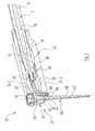
- FIG. 7
- a slightly perspective longitudinal center section through the coupling head of a further embodiment of an ultrasonic handpiece,
- FIG. 8
- a bottom view of the ultrasonic handpiece according to the
FIG. 7 ,
Ein in den
Die translatorischen Oszillationsschwingungen treten parallel zur Längsachse der Antriebseinheit 12 auf und werden auf eine Sonotrode 14 geleitet, die mit einem Piezoantrieb 16 verbunden ist.The translatory oscillation oscillations occur parallel to the longitudinal axis of the
Auf das Ende der Sonotrode 14 ist ein einstückig ausgebildeter, aus gut schwingendem Metall wie Titan hergestellter Umlenkkopf 24 mit einem mittigen Koppelsteg 26 aufgeschraubt. Damit führt die von der Sonotrode 14 übertragene translatorische Oszillationsbewegung zu einer bereichsweisen transversalen elastischen Biegung der in
Zugleich werden vertikale Arme 24-3 und 24-4 des Umlenkkopfes 24, die größere Dicke haben, im wesentlichen senkrecht zur Längsachse des Gerätes bewegt. Die Oszillationsbewegung des Balkens 24-4 wird zum Antreiben eines endseitig am Umlenkkopf 24 anbringbaren Werkzeuges 28 genutzt. Hierzu ist der Balken 24-4 als Spannkopf 25 ausgebildet.At the same time, vertical arms 24-3 and 24-4 of the
Das Werkzeug 28 ist dabei in einer Werkzeugaufnahme 30 aufgenommen, die anhand der
Durch die Sonotrode 14 erstreckt sich eine in der
Wie aus den
Durch die Durchbrüche 34, 36 bzw. die Balken 24-1 bis 24-4 und die Elastizität des Metallmaterials, aus dem der Umlenkkopf 24 hergestellt ist, wird ein schwingungsfähiger Rahmen gebildet, der die in der Geräteachse erfolgende und über den Koppelsteg 26 eingeleitete Oszillationsbewegung des Ultraschallschwingers in eine zur Geräteachse senkrechte Oszillationsbewegung des Werkzeugs 28 umgesetzt.Through the
Das Werkzeug 28 hat einen zylindrischen Schaftabschnitt 42 und einen sich zum freien Ende hin verjüngenden Arbeitsabschnitt.The
Es wird nun insbesondere auf die
Zur Festlegung des Werkzeugs 28 am Spannkopf 25 weist der Schaftabschnitt 42 einen rotationssymmetrischen Schaftkopf 40 auf, der eine konusförmige in der Zeichnung untere Anlagefläche 44 und eine sich daran anschließenden zylindrische Umfangsfläche 46 hat. Die Werkzeugaufnahme 30 weist ihrerseits eine an den Maximaldurchmesser des Werkzeugschafts 42 angepasste Bohrung 48 auf, durch die der Werkzeugschaft 42 hindurchgesteckt werden kann.To fix the
An die Bohrung 48 schließt sich eine konusförmige Stützfläche 50 an, die als Auflagefläche für die Anlagefläche 44 des Werkzeugs 28 dient. Die Stützfläche 50 geht in eine Gewindebohrung 52 über, die einen größeren Durchmesser als die Bohrung 48 für den Werkzeugschaft 42 aufweist und die zur Aufnahme der Feststellschraube 32 dient.The
Grundsätzlich könnte das Werkzeug 28 nach Entfernen der Feststellschraube 32 in der Zeichnung nach oben aus der Werkzeugaufnahme 30 entnommen werden. Allerdings müsste hierzu die Feststellschraube 32 vollständig entnommen werden. Dies ist aber zeitraubend und es ist hiermit auch die Gefahr eines Verlusts der Feststellschraube 32 gegeben. Zudem kann ein neuerliches Einschrauben der Feststellschraube 32 zu Handhabungsproblemen beim korrekten Ansetzen des Außengewindes der Feststellschraube führen.In principle, the
Aus diesem Grund ist der Umlenkkopf 24 mit einem Entnahmeschlitz 54 versehen, der ein korrespondierend zur Längskontur des Werkzeugs 28 ausgeführtes Profil aufweist und der ausgehend von einer Stirnseite 68 des Umlenkkopfs 24 zur Werkzeugaufnahme 30 verläuft.For this reason, the
Der Entnahmeschlitz 54 ist dabei so angeordnet, dass das Werkzeug 28 nur dann ausgetauscht werden kann, wenn die Feststellschraube 32 um eine erhebliche Strecke aus der in den
Bei flächiger Anlage der Feststellschraube 32 am Werkzeug 28 ist eine spielfreie Festlegung des Werkzeugs 28 in der Werkzugaufnahme 30 und eine reibschlüssige Verriegelung des Festellschraube 32 in ihrer Verriegelungsposition gewährleistet. Hierzu sind zusammenarbeitende Endflächen 60, 62 von Feststellschraube 32 und Werkzeugschaft 42 beide eben und senkrecht zur Achse der Werkzeugaufnahme 30.In flat contact the locking
Mit dem Lösen der Feststellschraube 32 wird zunächst die spielfreie Fixierung des Werkzeugs 28 in der Werkzeugaufnahme 30 aufgehoben, jedoch ohne dass das Werkzeug 28 durch den Entnahmeschlitz 54 schon entnommen werden kann. Dies ist erst möglich, wenn die Feststellschraube 32 vom Benutzer bewusst in eine Entriegelungsstellung gebracht wird, beispielsweise durch Drehung um einige volle Umdrehungen, in der zumindest nahezu der volle Querschnitt des Entnahmeschlitzes 54 von der Feststellschraube 32 freigegeben wird. Nur wenn dies der Fall ist, kann das Werkzeug 28 durch den Entnahmeschlitz 54 aus der Werkzeugaufnahme 30 entnommen werden.With the release of the locking
In der Werkzeugaufnahme 30 bildet die Stützfläche 50 einen ersten Hinterschnitt, durch den der Schaftkopf 40 des Werkzeugs 28 in einer ersten Axialrichtung (zur Spitze des Werkzeuges 28 hin) parallel zu seiner Mittelachse 56 festgelegt werden kann. Dabei arbeitet die Stützfläche 50 mit der Anlagefläche 44 zusammen.In the
Eine Flächennormale 58 der Stützfläche 50 bildet einen spitzen Winkel α zur Mittelachse 56 von Werkzeug 28 und Werkzeugaufnahme 30.A surface normal 58 of the
Für eine axiale Abstützung des Werkzeugs 28 am Umlenkkopf 24 in der zweiten axialen Richtung (in der Zeichnung nach oben) dient die Feststellschraube 32.For axial support of the
Die dem Werkzeugschaft 42 zugewandte Stirnseite 60 der Feststellschraube 32 ist ebenso wie die Oberseite 62 des Werkzeugschaftes 42 als transversale Planfläche ausgebildet und ermöglicht eine vollständige axial formschlüssige und umfangsmässig reibschlüssige Festlegung des Werkzeugs 28 am Umlenkkopf 24. Eine Flächennormale der Stirnseite 60 ist parallel zur Mittelachse 56 ausgerichtet.The
Gemäß den
Von der Vorderseite des Umlenkkopfes 24 her ist die Führungsbohrung 64 über einen eine Verlängerung des Entnahmeschlitzes 54 darstellenden Schlitz 70 zugänglich. Die Schlitze 70 und 72 bilden somit zusammen eine T-förmige Schlitzanordnung.From the front side of the
In der Führungsbohrung 64 wird ein auslaßseitiger Endbereich eines flexiblen Schlauchs 22 gehalten, dessen einlaßseitiger Endbereich am Schlauchstutzen 20 der Sonotrode 14 dicht festgelegt ist. Durch den wegen des Schlitzes 72 C-förmigen transversalen Querschnitt der Wand der Führungsbohrung 64 kann der Schlauch 22, der etwas größeren Durchmesser hat als die Bohrung 48 unter elastischer Verformung einfach vom Schlitz 72 her formschlüssig in die Führungsbohrung 64 eingeclipst werden. Durch eine nur lose formschlüssige Aufnahme des Schlauchs 22 in der Führungsbohrung 64 werden unerwünschte Schwingungsankopplungen des Schlauches 22 an den Umlenkkopf 24 und eine dadurch bedingte Erwärmung des Schlauchs 22 vermieden. Diesen Effekt kann man noch dadurch verstärken, dass man die Wandstärke des Schlauches vom einlaßseitigen Ende zum auslassseitigen Ende hin abnehmen läßt.In the guide bore 64, an outlet-side end portion of a
Durch die Antriebseinheit 12 hindurch kann ein ggf. abrasive Partikel enthaltendes Arbeitsfluid in den Schlauch 22 eingespeist werden und tritt an dem in der Führungsbohrung 64 aufgenommenen Ende des Schlauchs 22 in die Umgebung aus.Through the
Der größte Teil des Arbeitsfluids trifft so auf das Werkzeug 28 bzw. auf die mit dem Werkzeug 28 zu bearbeitende dentale Oberfläche auf. Dadurch wird ein effizienter Einsatz des Arbeitsfluids gewährleistet, das somit punktgenau an den Einsatzort dosiert werden kann.The largest part of the working fluid thus impinges on the
Eine Demontage des Schlauchs 22 wird vorzugsweise so vorgenommen, dass zunächst das Werkzeug 28 aus der Werkzeugaufnahme 30 entnommen wird, um den Schlitz 72 freizugeben. Anschließend wird der Schlauch 22 aus der Führungsbohrung 64, in die er formschlüssig eingeclipst ist, entnommen und erstreckt sich nunmehr im Wesentlichen parallel zur Längsachse des Umlenkkopfes 24. Anschließend wird der Schlauch 22 nach vorne von dem in den Durchbruch 36 hineinragenden Schlauchstutzen 20 abgezogen.A disassembly of the
Ein neuer Schlauch 22 wird in umgekehrter Reihenfolge zunächst auf den Schlauchstutzen 20 aufgeschoben und wird dann um 90° gebogen und in die Führungsbohrung 64 eingeclipst.A
Der Schlauch 22 ist vorzugsweise aus einem Elastomer, insbesondere einem weichen Silikonmaterial, hergestellt , also einem flexiblen Kunststoffmaterial. Besonders vorteilhaft ist es, wenn die Wandstärke des Schlauchs auf den durch den Abstand und die Ausrichtung des Schlauchstutzens 20 und der Führungsbohrung 64 bestimmten Biegeradius abgestimmt ist, so dass der Schlauch 22 nicht kollabiert, was den Strom des Arbeitsfluids behindern würde.The
Die in den
Die Wandstärke des Koppelabschnitts 23a entspricht im Wesentlichen der Wandstärke des sich daran anschließenden Austrittsabschnitts 23b. Bedingt durch den größeren Radius bzw. Außendurchmesser des Koppelabschnitts 23a kann dieser trotz der aus Gründen einer vereinfachten Montage kurz gehaltenen freien Länge des Schlauchstutzens 20a die Distanz bis zum vorderen Ende des Durchbruchs 36 freitragend überspannen und bedarf keiner weiteren Abstützung am Umlenkkopf 24.The wall thickness of the
Der sich an den Koppelabschnitt 23a anschließende Austrittsabschnitt 23b weist einen geringeren Außendurchmesser als der Koppelabschnitt 23a auf und ist bereits in die in
Durch die vorgeformte Ausführung des Schlauchs 22a wird eine Verdrehsicherung erreicht, so dass während des Betriebs des Ultraschall-Handstücks 10 kein unerwünschtes Verdrehen des Schlauchs 22a gegenüber dem Schlauchstutzen 20a zu erwarten ist.Due to the preformed design of the
Mit dem frei von Sicherungsrippen ausgeführten, zylinderhülsenförmigen Schlauchstutzen 20a ist ein einfaches Aufstecken und Abnehmen des Schlauchs 22a gewährleistet, da keine lokale Deformation des Koppelabschnitts 23a zum Aufschieben auf den Schlauchstutzen 20a erfolgen muss. Die achsiale Länge des Koppelabschnitts 23a ist so bemessen, dass bei vollständig auf den Schlauchstutzen 20a aufgeschobenem Schlauch 22a ein Luftspalt zwischen einer Stirnfläche 23c des Koppelabschnitts 23a und der Innenfläche des Durchbruchs 36 vorliegt. Dieser Luftspalt ist derart bemessen, dass auch bei einer Maximalamplitude des Umlenkkopfs 24 keine, zumindest keine nennenswerte Berührung der Stirnfläche 23c und dem Umlenkkopf 24 stattfindet. Dadurch wird eine unerwünschte Übertragung von Ultraschallenergie vom Umlenkkopf 24 auf den Schlauch 22a vermindert bzw. verhindert.With the free of securing ribs, cylindrical sleeve-shaped
Nach Einsetzen des Werkzeugs 28in den Umlenkkopf 24 wird anhand der Geometrie des Koppelabschnitts 23a ein Entnehmen aus dem Durchbruch verhindert, da der angeformte, gekrümmte Austrittsabschnitt 23b derart in der bereichsweise vom Werkzeug 28 verschlossenen Schlauch-Führungsbohrung 64 aufgenommen ist, dass kein Entweichen möglich ist.After insertion of the
Aus der
Bei einer nicht dargestellten weiteren Ausführungsform der Erfindung kann der Schlauch 22 mit einem im Schlauchmaterial integrierten Verstärkungsmaterial, insbesondere einem Verstärkungsgewebe aus Kunststoff oder Drahtgeflecht versehen sein, um auch bei kleinen Biegeradien einen freien Durchgang des Arbeitsfluids zu gewährleisten.In a further embodiment of the invention, not shown, the
Während der Umlenkkopf 24 vorzugsweise aus dem besonders zähen und hochfesten Material Titan hergestellt ist, wird als Material für die Feststellschraube 32 Bronze, Messing oder ein Kunststoffmaterial mit hoher Dichte, insbesondere Polytetrafluorethylen (PTFE), Polyaryletherketon (PAEK) oder Polyethyletherketon (PEEK) verwendet.While the
Bei einer ebenfalls nicht dargestellten Ausführungsform der Erfindung sind das Werkzeug und die Feststellschraube einstückig miteinander ausgeführt. Dies ermöglicht einen raschen Werkzeugwechsel und eine zuverlässige, formschlüssige Festlegung des Werkzeugs am Umlenkkopf.In an embodiment of the invention, also not shown, the tool and the locking screw are integral with each other. This enables a rapid tool change and a reliable, positive fixing of the tool on the deflection.
Claims (17)
Translated fromGermandadurch gekennzeichnet, dass der Kupplungsstutzen (20) vorzugsweise einen oder mehrere umlaufende Sicherungsrippen (21) aufweist, die eine zuverlässige, kraftschlüssige Verriegelung des flexiblen Endabschnitts (22) auf dem Kupplungsstutzen (20) gewährleisten.Ultrasonic handpiece according to one of claims 2 to 12,
characterized in that the coupling piece (20) preferably one or more circumferential locking ribs (21), which ensure a reliable, non-positive locking of the flexible end portion (22) on the coupling piece (20).
Applications Claiming Priority (1)
| Application Number | Priority Date | Filing Date | Title |
|---|---|---|---|
| DE102007049514ADE102007049514A1 (en) | 2007-10-15 | 2007-10-15 | Ultrasonic handpiece |
Publications (1)
| Publication Number | Publication Date |
|---|---|
| EP2050414A1true EP2050414A1 (en) | 2009-04-22 |
Family
ID=40280733
Family Applications (1)
| Application Number | Title | Priority Date | Filing Date |
|---|---|---|---|
| EP08017444AWithdrawnEP2050414A1 (en) | 2007-10-15 | 2008-10-04 | Ultrasonic handpiece |
Country Status (3)
| Country | Link |
|---|---|
| US (1) | US20090098507A1 (en) |
| EP (1) | EP2050414A1 (en) |
| DE (1) | DE102007049514A1 (en) |
Families Citing this family (4)
| Publication number | Priority date | Publication date | Assignee | Title |
|---|---|---|---|---|
| DE102010049886B4 (en) | 2010-11-01 | 2014-01-09 | Ernst-Moritz-Arndt-Universität Greifswald | Surgical tool for performing a bone resection |
| US9463042B2 (en) | 2011-06-13 | 2016-10-11 | P Tech, Llc | Methods and systems for controlling an ultrasonic handpiece based on sensed pressure |
| US9839492B2 (en)* | 2013-09-05 | 2017-12-12 | Heriberto Bujanda Wong | Ultrasonic ring tip to activate endodontic instruments |
| JP7279912B2 (en)* | 2018-10-05 | 2023-05-23 | 医療法人社団プレシャスワン | Interdental space-making device and space-making method |
Citations (5)
| Publication number | Priority date | Publication date | Assignee | Title |
|---|---|---|---|---|
| GB391437A (en)* | 1931-10-12 | 1933-04-12 | Frank Popper | Improvements in or relating to dental instruments |
| US3526036A (en)* | 1968-04-01 | 1970-09-01 | Sven Karl Lennart Goof | Ultrasonic dental apparatus |
| US4911639A (en)* | 1985-11-21 | 1990-03-27 | Jacklich John J | Handpiece for use in root canal procedures |
| US20060240381A1 (en)* | 1995-08-31 | 2006-10-26 | Biolase Technology, Inc. | Fluid conditioning system |
| DE102005044074A1 (en) | 2005-09-15 | 2007-03-22 | Dürr Dental GmbH & Co. KG | driving element |
- 2007
- 2007-10-15DEDE102007049514Apatent/DE102007049514A1/ennot_activeWithdrawn
- 2008
- 2008-10-04EPEP08017444Apatent/EP2050414A1/ennot_activeWithdrawn
- 2008-10-14USUS12/251,111patent/US20090098507A1/ennot_activeAbandoned
Patent Citations (5)
| Publication number | Priority date | Publication date | Assignee | Title |
|---|---|---|---|---|
| GB391437A (en)* | 1931-10-12 | 1933-04-12 | Frank Popper | Improvements in or relating to dental instruments |
| US3526036A (en)* | 1968-04-01 | 1970-09-01 | Sven Karl Lennart Goof | Ultrasonic dental apparatus |
| US4911639A (en)* | 1985-11-21 | 1990-03-27 | Jacklich John J | Handpiece for use in root canal procedures |
| US20060240381A1 (en)* | 1995-08-31 | 2006-10-26 | Biolase Technology, Inc. | Fluid conditioning system |
| DE102005044074A1 (en) | 2005-09-15 | 2007-03-22 | Dürr Dental GmbH & Co. KG | driving element |
Also Published As
| Publication number | Publication date |
|---|---|
| US20090098507A1 (en) | 2009-04-16 |
| DE102007049514A1 (en) | 2009-04-16 |
Similar Documents
| Publication | Publication Date | Title |
|---|---|---|
| DE10103218B4 (en) | Quick dismountable nozzle arrangement | |
| DE2508175C2 (en) | Ultrasonic tool | |
| EP2027931B1 (en) | Connector for joining a material supply device to an injection pistol | |
| AT409821B (en) | MEDICAL OR DENTAL MEDICAL TREATMENT INSTRUMENT WITH A PARTICULARLY PNEUMATIC VIBRATION DRIVE | |
| DE2452708A1 (en) | FITTED PIPE | |
| DE69830527T2 (en) | Hochdruckreinigungsdüse | |
| EP2050414A1 (en) | Ultrasonic handpiece | |
| EP1710034A1 (en) | Clamping device for harmonically vibrating components | |
| EP2369943B1 (en) | Connecting piece | |
| EP1569755A1 (en) | Nozzle assembly for a high-pressure cleaning device | |
| DE10233862B4 (en) | A system for connecting a tubular conduit to a connection device, method for machining an end portion of the tubular conduit and associated tool | |
| EP2743919B1 (en) | Device for applying ultrasound to liquid media through a membrane and ultrasound system | |
| DE102014202339B4 (en) | Spray head for applying and distributing liquids in minimal quantities | |
| EP3180543B1 (en) | Vibration element with decoupled component | |
| EP2050413A1 (en) | Ultrasound tool holder and tool for same | |
| EP1412117B1 (en) | Spacer element for a collet chuck and collet chuck | |
| EP3335807A1 (en) | Sonotrode and vibrating unit with such a sonotrode | |
| EP4135929A1 (en) | Device and method for connecting a cooling nozzle to a cooling lubricant supply | |
| DE2107526C3 (en) | Dental ultrasound machine | |
| DE2923711A1 (en) | Ultrasonic surgical and dental probe - has piezoelectric crystal transducer in hollow connecting rod and electrode to apply AC voltage to transducer | |
| DE102004007413A1 (en) | Tool holder for a dental tool that uses a liquid medium has a circular gasket with an associated elastic sealing ring arranged between the tool receiving housing and the tool shaft | |
| DE202010004649U1 (en) | Injectors | |
| EP2730342A1 (en) | Hot melt glue applicator and a system with such a glue applicator and a glue stick | |
| WO2005061938A1 (en) | Hose clamping device | |
| AT400511B (en) | Toothcare unit |
Legal Events
| Date | Code | Title | Description |
|---|---|---|---|
| PUAI | Public reference made under article 153(3) epc to a published international application that has entered the european phase | Free format text:ORIGINAL CODE: 0009012 | |
| AK | Designated contracting states | Kind code of ref document:A1 Designated state(s):AT BE BG CH CY CZ DE DK EE ES FI FR GB GR HR HU IE IS IT LI LT LU LV MC MT NL NO PL PT RO SE SI SK TR | |
| AX | Request for extension of the european patent | Extension state:AL BA MK RS | |
| AKX | Designation fees paid | ||
| 17P | Request for examination filed | Effective date:20090604 | |
| RBV | Designated contracting states (corrected) | Designated state(s):CH DE FR IT LI | |
| 17Q | First examination report despatched | Effective date:20100113 | |
| STAA | Information on the status of an ep patent application or granted ep patent | Free format text:STATUS: THE APPLICATION IS DEEMED TO BE WITHDRAWN | |
| 18D | Application deemed to be withdrawn | Effective date:20100724 |