EP2049766B1 - Method for flow control and autonomous valve or flow control device - Google Patents
Method for flow control and autonomous valve or flow control deviceDownload PDFInfo
- Publication number
- EP2049766B1 EP2049766B1EP07768930.5AEP07768930AEP2049766B1EP 2049766 B1EP2049766 B1EP 2049766B1EP 07768930 AEP07768930 AEP 07768930AEP 2049766 B1EP2049766 B1EP 2049766B1
- Authority
- EP
- European Patent Office
- Prior art keywords
- disc
- control device
- flow control
- fluid
- self
- Prior art date
- Legal status (The legal status is an assumption and is not a legal conclusion. Google has not performed a legal analysis and makes no representation as to the accuracy of the status listed.)
- Active
Links
Images


Classifications
- E—FIXED CONSTRUCTIONS
- E21—EARTH OR ROCK DRILLING; MINING
- E21B—EARTH OR ROCK DRILLING; OBTAINING OIL, GAS, WATER, SOLUBLE OR MELTABLE MATERIALS OR A SLURRY OF MINERALS FROM WELLS
- E21B34/00—Valve arrangements for boreholes or wells
- E21B34/06—Valve arrangements for boreholes or wells in wells
- E21B34/08—Valve arrangements for boreholes or wells in wells responsive to flow or pressure of the fluid obtained
- E—FIXED CONSTRUCTIONS
- E21—EARTH OR ROCK DRILLING; MINING
- E21B—EARTH OR ROCK DRILLING; OBTAINING OIL, GAS, WATER, SOLUBLE OR MELTABLE MATERIALS OR A SLURRY OF MINERALS FROM WELLS
- E21B34/00—Valve arrangements for boreholes or wells
- E—FIXED CONSTRUCTIONS
- E21—EARTH OR ROCK DRILLING; MINING
- E21B—EARTH OR ROCK DRILLING; OBTAINING OIL, GAS, WATER, SOLUBLE OR MELTABLE MATERIALS OR A SLURRY OF MINERALS FROM WELLS
- E21B43/00—Methods or apparatus for obtaining oil, gas, water, soluble or meltable materials or a slurry of minerals from wells
- E21B43/12—Methods or apparatus for controlling the flow of the obtained fluid to or in wells
- E—FIXED CONSTRUCTIONS
- E21—EARTH OR ROCK DRILLING; MINING
- E21B—EARTH OR ROCK DRILLING; OBTAINING OIL, GAS, WATER, SOLUBLE OR MELTABLE MATERIALS OR A SLURRY OF MINERALS FROM WELLS
- E21B43/00—Methods or apparatus for obtaining oil, gas, water, soluble or meltable materials or a slurry of minerals from wells
- E21B43/32—Preventing gas- or water-coning phenomena, i.e. the formation of a conical column of gas or water around wells
- F—MECHANICAL ENGINEERING; LIGHTING; HEATING; WEAPONS; BLASTING
- F16—ENGINEERING ELEMENTS AND UNITS; GENERAL MEASURES FOR PRODUCING AND MAINTAINING EFFECTIVE FUNCTIONING OF MACHINES OR INSTALLATIONS; THERMAL INSULATION IN GENERAL
- F16K—VALVES; TAPS; COCKS; ACTUATING-FLOATS; DEVICES FOR VENTING OR AERATING
- F16K15/00—Check valves
- F16K15/02—Check valves with guided rigid valve members
- F16K15/021—Check valves with guided rigid valve members the valve member being a movable body around which the medium flows when the valve is open
- F16K15/023—Check valves with guided rigid valve members the valve member being a movable body around which the medium flows when the valve is open the valve member consisting only of a predominantly disc-shaped flat element
- G—PHYSICS
- G05—CONTROLLING; REGULATING
- G05D—SYSTEMS FOR CONTROLLING OR REGULATING NON-ELECTRIC VARIABLES
- G05D7/00—Control of flow
- G05D7/01—Control of flow without auxiliary power
- G05D7/0146—Control of flow without auxiliary power the in-line sensing element being a piston or float without flexible member or spring
Definitions
- Embodiments of the present inventiongenerally provide a self-adjustable flow control device for controlling the flow of a fluid from one space to another, fluid flow arrangements comprising the self-adjustable flow control device, a system comprising a plurality of self-adjustable flow control devices, and a method for autonomously adjusting the flow of a fluid through a flow control device.
- WO-A-9208875describes a horizontal production pipe comprising a plurality of production sections connected by mixing chambers having a larger internal diameter than the production sections.
- the production sectionscomprise an external slotted liner which can be considered as performing a filtering action.
- the sequence of sections of different diametercreates flow turbulence and prevent the running of work-over tools.
- US2006/0027377describes one-way valves for use in well fluid control.
- US6354378 B1describes a method and apparatus for formation isolation in a well.
- US2005/072578 A1describes thermally-controlled valves and methods of using the same in a wellbore.
- fluids of different qualitiesi.e. oil, gas, water (and sand) is produced in different amounts and mixtures depending on the property or quality of the formation.
- known devicesare able to distinguish between and control the inflow of oil, gas or water on the basis of their relative composition and/or quality.
- a self-adjustable flow control devicefor controlling the flow of a fluid from one space to another, as defined by independent claim 1.
- a fluid flow arrangementcomprising the self-adjustable flow control device.
- a systemcomprising a plurality of the self-adjustable flow control devices and preferably comprising the fluid flow control arrangement.
- the followingrelates to a method for self-adjusting (autonomously adjusting) the flow of a fluid through a valve or flow control device, and a self adjusting valve or flow control device.
- Thisis in particular useful in a production pipe for producing oil and/or gas from a well in an oil and/or gas reservoir, which production pipe includes a lower drainage pipe preferably being divided into at least two sections each including one or more inflow control devices which communicates the geological production formation with the flow space of the drainage pipe.
- inflow control devicewhich is self adjusting or autonomous and can easily be fitted in the wall of a production pipe and which therefore provide for the use of work-over tools.
- the deviceis designed to "distinguish" between the oil and/or gas and/or water and is able to control the flow or inflow of oil or gas, depending on for which of these fluids such flow control is required.
- the deviceis robust, can withstand large forces and high temperatures, prevents draw dawns (differential pressure) needs no energy supply, can withstand sand production, is reliable, but is still simple and very cheap.
- a methodis characterized in that the fluid flows through an inlet or aperture thereby forming a flow path through the control device passing by a movable disc or body which is designed to move freely relative to the opening of the inlet and thereby reduce or increase the flow-through area by exploiting the Bernoulli effect and any stagnation pressure created over the disc, whereby the control device, depending on the composition of the fluid and its properties, autonomously adjusts the flow of the fluid based on a pre-estimated flow design.
- a self-adjusting valve or control device of an embodimentis characterized in that the control device is a separate or integral part of the fluid flow control arrangement, including a disc or freely movable controlling body being provided in a recess of the pipe wall or being provided in a separate housing body in the wall, the disc or controlling body facing the outlet of an aperture or hole in the centre of the recess or housing body and being held in place in the recess or housing body by means of a holder device or arrangement, thereby forming a flow path where the fluid enters the control device through the central aperture or inlet flowing towards and along the disc or body and out of the recess or housing.
- Fig. 1shows, as stated above, a section of a production pipe 1 in which a prototype of a control device 2 according to an embodiment of the invention is provided.
- the control device 2is preferably of circular, relatively flat shape and may be provided with external threads 3 (see Fig. 2 ) to be screwed into a circular hole with corresponding internal threads in the pipe.
- the device 2may be adapted to the thickness of the pipe and fit within its outer and inner periphery.
- Fig. 2 a) and b)shows the control device 2 in larger scale.
- the deviceconsists of first disc-shaped housing body 4 with an outer cylindrical segment 5 and inner cylindrical segment 6 and with a central hole or aperture 10, and a second disc-shaped holder body 7 with an outer cylindrical segment 8, as well as a preferably flat disc or freely movable body 9 provided in an open space 14 formed between the first 4 and second 7 disc-shaped housing and holder bodies.
- the body 9may for particular applications and adjustments depart from the flat shape and have a partly conical or semicircular shape (for instance towards the aperture 10.)
- the cylindrical segment 8 of the second disc-shaped holder body 7fits within and protrudes in the opposite direction of the outer cylindrical segment 5 of the first disc-shaped housing body 4 thereby forming a flow path as shown by the arrows 11, where the fluid enters the control device through the central hole or aperture (inlet) 10 and flows towards and radially along the disc 9 before flowing through the annular opening 12 formed between the cylindrical segments 8 and 6 and further out through the annular opening 13 formed between the cylindrical segments 8 and 5.
- the two disc-shaped housing and holder bodies 4, 7are attached to one another by a screw connection, welding or other means (not further shown in the figures) at a connection area 15 as shown in Fig 2b ).
- Embodiments of the present inventionexploit the effect of Bernoulli teaching that the sum of static pressure, dynamic pressure and friction is constant along a flow line: P static + 1 2 ⁇ v 2 + ⁇ P friction
- the flow areawill decrease when the differential pressure increases, such that the volume flow through the control device will not, or nearly not, increase when the pressure drop increases.
- a comparison between a control device according to embodiments of the present invention with movable disc and a control device with fixed flow-through openingis shown in Fig. 3 , and as can be seen from the figure, the flow-through volume for embodiments of the present invention is constant above a given differential pressure.
- the control deviceWhen producing oil and gas the control device according to embodiments of the invention may have two different applications: Using it as inflow control device to reduce inflow of water, or using it to reduce inflow of gas at gas break through situations.
- the different areas and pressure zonesAs shown in Fig. 4 , will have impact on the efficiency and flow through properties of the device. Referring to Fig. 4 , the different area/pressure zones may be divided into:
- Fluids with different viscositieswill provide different forces in each zone depending on the design of these zones.
- the design of the areaswill be different for different applications, e.g. gas/oil or oil/water flow.
- the areasneeds to be carefully balanced and optimally designed taking into account the properties and physical conditions (viscosity, temperature, pressure etc.) for each design situation.
- Fig. 5shows a principal sketch of another embodiment of the control device not part of the invention, which is of a more simple design than the version shown in Fig. 2 .
- the control device 2consists, as with the version shown in Fig. 2 , of a first disc-shaped housing body 4 with an outer cylindrical segment 5 and with a central hole or aperture 10, and a second disc-shaped holder body 17 attached to the segment 5 of the housing body 4, as well as a preferably flat disc 9 provided in an open space 14 formed between the first and second disc-shaped housing and holder bodies 4, 17.
- Fig. 6shows a third embodiment according to the invention where the design is the same as with the example shown in Fig. 2 , but where a spring element 18, in the form of a spiral or other suitable spring device, is provided on either side of the disc and connects the disc with the holder (J, 22), recess (21 ) or housing (4).
- the spring element 18is used to balance and control the inflow area between the disc 9 and the inlet 10, or rather the surrounding edge or seat 19 of the inlet 10.
- the opening between the disc 9 and edge 19will be larger or smaller, and with a suitable selected spring constant, depending on the inflow and pressure conditions at the selected place where the control device is provided, constant mass flow through the device may be obtained.
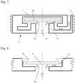
- Fig. 7shows a fourth embodiment of the invention, where the design is the same as with the example in Fig. 6 above, but where the disc 9 is, on the side facing the inlet opening 10, provided with a thermally responsive device such as bi-metallic element 20.
- the conditionsmay rapidly change from a situation where only or mostly oil is produced to a situation where only or mostly gas is produced (gas break-through or gas coning).
- a pressure drop of 16 bar from 100 barthe temperature drop would correspond to approximately 20°C.
- the disc 9By providing the disc 9 with a thermally responsive element such as a bi-metallic element as shown in Fig. 7 , the disc will bend upwards or be moved upwards by the element 20 abutting the holder shaped body 7 and thereby narrowing the opening between the disc and the inlet 10 or fully closing said inlet.
- control deviceas shown in Figs. 1 and 2 and 4 , 6 and 7 are all related to solutions where the control device as such is a separate unit or device to be provided in conjunction with a fluid flow situation or arrangement such as the wall of a production pipe in connection with the production of oil and gas.
- the control devicemay, as shown in Fig. 8 , not part of the invention, be an integral part of the fluid flow arrangement, whereby the disc 9 may be provided in a recess 21 facing the outlet of an aperture or hole 10 of for instance a wall of a pipe 1 as shown in Fig. 1 instead of being provided in a separate housing body 4.
- the discmay be held in place in the recess by means of a holder device such as inwardly protruding spikes, a circular ring 22 or the like being connected to the outer opening of the recess by means of screwing, welding or the like.
- a holder devicesuch as inwardly protruding spikes, a circular ring 22 or the like being connected to the outer opening of the recess by means of screwing, welding or the like.
- Embodimentsare not restricted to the application related to inflow of oil and/or gas from a well as described above or when injecting gas (natural gas, air or CO 2 ), steam or water into an oil and/or gas producing well.
- gasnatural gas, air or CO 2
- the inventionmay be used in any processes or process related application where the flow of fluids with different gas and/or liquid compositions need to be controlled.
Landscapes
- Engineering & Computer Science (AREA)
- Mining & Mineral Resources (AREA)
- Life Sciences & Earth Sciences (AREA)
- Geology (AREA)
- Physics & Mathematics (AREA)
- Geochemistry & Mineralogy (AREA)
- General Life Sciences & Earth Sciences (AREA)
- Environmental & Geological Engineering (AREA)
- Fluid Mechanics (AREA)
- General Engineering & Computer Science (AREA)
- Mechanical Engineering (AREA)
- Automation & Control Theory (AREA)
- General Physics & Mathematics (AREA)
- Pipe Accessories (AREA)
- Flow Control (AREA)
- Control Of Fluid Pressure (AREA)
- Accessories For Mixers (AREA)
- Physical Or Chemical Processes And Apparatus (AREA)
- Pipeline Systems (AREA)
- Cultivation Of Plants (AREA)
- Fats And Perfumes (AREA)
Description
- Embodiments of the present invention generally provide a self-adjustable flow control device for controlling the flow of a fluid from one space to another, fluid flow arrangements comprising the self-adjustable flow control device, a system comprising a plurality of self-adjustable flow control devices, and a method for autonomously adjusting the flow of a fluid through a flow control device.
- Devices for recovering of oil and gas from long, horizontal and vertical wells are known from
US patent publications Nos. 4,821,801 ,4,858,691 ,4,577,691 andGB patent publication No. 2169018 - These known devices comprise a perforated drainage pipe with, for example, a filter for control of sand around the pipe. A considerable disadvantage with the known devices for oil/and or gas production in highly permeable geological formations is that the pressure in the drainage pipe increases exponentially in the upstream direction as a result of the flow friction in the pipe. Because the differential pressure between the reservoir and the drainage pipe will decrease upstream as a result, the quantity of oil and/or gas flowing from the reservoir into the drainage pipe will decrease correspondingly. The total oil and /or gas produced by this means will therefore be low. With thin oil zones and highly permeable geological formations, there is further a high risk that of coning, i. e. flow of unwanted water or gas into the drainage pipe downstream, where the velocity of the oil flow from the reservoir to the pipe is the greatest.
- FromWorld Oil, vol. 212, N. 11 (11/91), pages 73 - 80, is previously known to divide a drainage pipe into sections with one or more inflow restriction devices such as sliding sleeves or throttling devices. However, this reference is mainly dealing with the use of inflow control to limit the inflow rate for up hole zones and thereby avoid or reduce coning of water and or gas.
WO-A-9208875 US2006/0027377 describes one-way valves for use in well fluid control.US6354378 B1 describes a method and apparatus for formation isolation in a well.US2005/072578 A1 describes thermally-controlled valves and methods of using the same in a wellbore.- When extracting oil and/or gas from geological production formations, fluids of different qualities, i.e. oil, gas, water (and sand) is produced in different amounts and mixtures depending on the property or quality of the formation. None of the above-mentioned, known devices are able to distinguish between and control the inflow of oil, gas or water on the basis of their relative composition and/or quality.
- According to an aspect of the present invention, there is a provided a self-adjustable flow control device for controlling the flow of a fluid from one space to another, as defined by
independent claim 1. - There may further be provided a fluid flow arrangement comprising the self-adjustable flow control device.
- There may further be provided a system comprising a plurality of the self-adjustable flow control devices and preferably comprising the fluid flow control arrangement.
- There may further be provided a method for autonomously adjusting the flow of a fluid through a flow control device, the method comprising using the self-adjustable flow control device.
- Preferred embodiments are defined in the dependent claims.
- Embodiments of the present invention will be further described in the following by means of examples and with reference to the drawings, where:
Fig. 1 shows a schematic view of a production pipe with a control device according to an embodiment of the present invention;Fig. 2 a) shows, in larger scale, a cross section of the control device according to an embodiment of the invention, b) shows the same device in a top view;Fig. 3 is a diagram showing the flow volume through a control device according to an embodiment of the invention vs. the differential pressure in comparison with a fixed inflow device;Fig. 4 shows the device shown inFig. 2 , but with the indication of different pressure zones influencing the design of the device for different applications;Fig. 5 shows a principal sketch of another embodiment of the control device not part of the invention;Fig. 6 shows a principal sketch of a third embodiment of the control device according to the invention;Fig. 7 shows a principal sketch of a fourth embodiment of the control device according to the invention; andFig. 8 shows a principal sketch of a fifth embodiment not part of the invention where the control device is an integral part of a flow arrangement.- The following relates to a method for self-adjusting (autonomously adjusting) the flow of a fluid through a valve or flow control device, and a self adjusting valve or flow control device. This is in particular useful in a production pipe for producing oil and/or gas from a well in an oil and/or gas reservoir, which production pipe includes a lower drainage pipe preferably being divided into at least two sections each including one or more inflow control devices which communicates the geological production formation with the flow space of the drainage pipe.
- We describe an inflow control device which is self adjusting or autonomous and can easily be fitted in the wall of a production pipe and which therefore provide for the use of work-over tools. The device is designed to "distinguish" between the oil and/or gas and/or water and is able to control the flow or inflow of oil or gas, depending on for which of these fluids such flow control is required.
- The device is robust, can withstand large forces and high temperatures, prevents draw dawns (differential pressure) needs no energy supply, can withstand sand production, is reliable, but is still simple and very cheap.
- A method is characterized in that the fluid flows through an inlet or aperture thereby forming a flow path through the control device passing by a movable disc or body which is designed to move freely relative to the opening of the inlet and thereby reduce or increase the flow-through area by exploiting the Bernoulli effect and any stagnation pressure created over the disc, whereby the control device, depending on the composition of the fluid and its properties, autonomously adjusts the flow of the fluid based on a pre-estimated flow design.
- A self-adjusting valve or control device of an embodiment is characterized in that the control device is a separate or integral part of the fluid flow control arrangement, including a disc or freely movable controlling body being provided in a recess of the pipe wall or being provided in a separate housing body in the wall, the disc or controlling body facing the outlet of an aperture or hole in the centre of the recess or housing body and being held in place in the recess or housing body by means of a holder device or arrangement, thereby forming a flow path where the fluid enters the control device through the central aperture or inlet flowing towards and along the disc or body and out of the recess or housing.
Fig. 1 shows, as stated above, a section of aproduction pipe 1 in which a prototype of acontrol device 2 according to an embodiment of the invention is provided. Thecontrol device 2 is preferably of circular, relatively flat shape and may be provided with external threads 3 (seeFig. 2 ) to be screwed into a circular hole with corresponding internal threads in the pipe. By controlling the thickness, thedevice 2 may be adapted to the thickness of the pipe and fit within its outer and inner periphery.Fig. 2 a) and b) shows thecontrol device 2 in larger scale. The device consists of first disc-shaped housing body 4 with an outercylindrical segment 5 and innercylindrical segment 6 and with a central hole oraperture 10, and a second disc-shaped holder body 7 with an outercylindrical segment 8, as well as a preferably flat disc or freelymovable body 9 provided in anopen space 14 formed between the first 4 and second 7 disc-shaped housing and holder bodies. Thebody 9 may for particular applications and adjustments depart from the flat shape and have a partly conical or semicircular shape (for instance towards theaperture 10.) As can be seen from the figure, thecylindrical segment 8 of the second disc-shaped holder body 7 fits within and protrudes in the opposite direction of the outercylindrical segment 5 of the first disc-shaped housing body 4 thereby forming a flow path as shown by thearrows 11, where the fluid enters the control device through the central hole or aperture (inlet) 10 and flows towards and radially along thedisc 9 before flowing through theannular opening 12 formed between thecylindrical segments annular opening 13 formed between thecylindrical segments holder bodies connection area 15 as shown inFig 2b ).- Embodiments of the present invention exploit the effect of Bernoulli teaching that the sum of static pressure, dynamic pressure and friction is constant along a flow line:

- When subjecting the
disc 9 to a fluid flow, which is the case with embodiments of the present invention, the pressure difference over thedisc 9 can be expressed as follows:
- Due to lower viscosity, a fluid such as gas will "make the turn later" and follow further along the disc towards its outer end (indicated by reference number 14). This makes a higher stagnation pressure in the
area 16 at the end of thedisc 9, which in turn makes a higher pressure over the disc. And thedisc 9, which is freely movable within the space between the disc-shaped bodies disc 9 and innercylindrical segment 6. Thus, thedisc 9 moves downwards or upwards depending on the viscosity of the fluid flowing through, whereby this principle can be used to control (close/open) the flow of fluid through of the device. - Further, the pressure drop through a traditional inflow control device (ICD) with fixed geometry will be proportional to the dynamic pressure:

Fig. 3 , and as can be seen from the figure, the flow-through volume for embodiments of the present invention is constant above a given differential pressure. - This represents a major advantage with embodiments of the present invention as it can be used to ensure the same volume flowing through each section for the entire horizontal well, which is not possible with fixed inflow control devices.
- When producing oil and gas the control device according to embodiments of the invention may have two different applications: Using it as inflow control device to reduce inflow of water, or using it to reduce inflow of gas at gas break through situations. When designing the control device according to embodiments of the invention for the different applications such as water or gas, as mentioned above, the different areas and pressure zones, as shown in
Fig. 4 , will have impact on the efficiency and flow through properties of the device. Referring toFig. 4 , the different area/pressure zones may be divided into: - A1, P1 is the inflow area and pressure respectively. The force (PrA1) generated by this prssure will strive to open the control device (move the
disc 9 upwards). - A2, P2 is the area and pressure in the zone where the velocity will be largest and hence represents a dynamic pressure source. The resulting force of the dynamic pressure will strive to close the control device (move the disc downwards as the flow velocity increases).
- A3, P3 is the area and pressure at the outlet. This should be the same as the well pressure (inlet pressure).
- A4i P4 is the area and pressure (stagnation pressure) behind the disc. The stagnation pressure, at position 16 (
Fig. 2 ), creates the pressure and the force behind the disc. This will strive to close the control device (move the disc downwards). - Fluids with different viscosities will provide different forces in each zone depending on the design of these zones. In order to optimize the efficiency and flow through properties of the control device, the design of the areas will be different for different applications, e.g. gas/oil or oil/water flow. Hence, for each application the areas needs to be carefully balanced and optimally designed taking into account the properties and physical conditions (viscosity, temperature, pressure etc.) for each design situation.
Fig. 5 shows a principal sketch of another embodiment of the control device not part of the invention, which is of a more simple design than the version shown inFig. 2 . Thecontrol device 2 consists, as with the version shown inFig. 2 , of a first disc-shapedhousing body 4 with an outercylindrical segment 5 and with a central hole oraperture 10, and a second disc-shapedholder body 17 attached to thesegment 5 of thehousing body 4, as well as a preferablyflat disc 9 provided in anopen space 14 formed between the first and second disc-shaped housing andholder bodies holder body 17 is inwardly open (through a hole or holes 23 etc.) and is now only holding the disc in place, and since thecylindrical segment 5 is shorter with a different flow path than what is shown inFig.2 , there is no build up of stagnation pressure (P4) on the back side of thedisc 9 as explained above in conjunction withFig. 4 . With this solution without stagnation pressure the building thickness for the device is lower and may withstand a larger amount of particles contained in the fluid.Fig. 6 shows a third embodiment according to the invention where the design is the same as with the example shown inFig. 2 , but where aspring element 18, in the form of a spiral or other suitable spring device, is provided on either side of the disc and connects the disc with the holder (J, 22), recess (21 ) or housing (4).- The
spring element 18 is used to balance and control the inflow area between thedisc 9 and theinlet 10, or rather the surrounding edge orseat 19 of theinlet 10. Thus, depending on the spring constant and thereby the spring force, the opening between thedisc 9 and edge 19 will be larger or smaller, and with a suitable selected spring constant, depending on the inflow and pressure conditions at the selected place where the control device is provided, constant mass flow through the device may be obtained.Fig. 7 shows a fourth embodiment of the invention, where the design is the same as with the example inFig. 6 above, but where thedisc 9 is, on the side facing theinlet opening 10, provided with a thermally responsive device such asbi-metallic element 20. When producing oil and/or gas the conditions may rapidly change from a situation where only or mostly oil is produced to a situation where only or mostly gas is produced (gas break-through or gas coning). With for instance a pressure drop of 16 bar from 100 bar the temperature drop would correspond to approximately 20°C. By providing thedisc 9 with a thermally responsive element such as a bi-metallic element as shown inFig. 7 , the disc will bend upwards or be moved upwards by theelement 20 abutting the holder shapedbody 7 and thereby narrowing the opening between the disc and theinlet 10 or fully closing said inlet. - The above examples of a control device according to the invention as shown in
Figs. 1 and2 and4 ,6 and7 are all related to solutions where the control device as such is a separate unit or device to be provided in conjunction with a fluid flow situation or arrangement such as the wall of a production pipe in connection with the production of oil and gas. However, the control device may, as shown inFig. 8 , not part of the invention, be an integral part of the fluid flow arrangement, whereby thedisc 9 may be provided in arecess 21 facing the outlet of an aperture orhole 10 of for instance a wall of apipe 1 as shown inFig. 1 instead of being provided in aseparate housing body 4. Further, the disc may be held in place in the recess by means of a holder device such as inwardly protruding spikes, acircular ring 22 or the like being connected to the outer opening of the recess by means of screwing, welding or the like. - Embodiments are not restricted to the application related to inflow of oil and/or gas from a well as described above or when injecting gas (natural gas, air or CO2), steam or water into an oil and/or gas producing well. Thus, the invention may be used in any processes or process related application where the flow of fluids with different gas and/or liquid compositions need to be controlled.


Claims (7)
- A self-adjustable flow control device (2) for controlling flow of a fluid from one space or area to another, useful at least for controlling flow of fluid, i.e. oil and/or gas including any water, from a reservoir and into a production pipe of a well in the oil and/or gas reservoir, which production pipe includes a lower drainage pipe, the device comprising:a basically flat disc (9), a holder device or arrangement and a recess (14), wherein the disc is provided in the recess (14) ,wherein the disc (9) faces an outlet of an aperture or hole (10) in the centre of the recess (14) and is held in place in the recess (14) by means of the holder device or arrangement, thereby allowing a said fluid to enter the control device (2) through the central aperture or hole (10) to flow towards and along the disc (9) and out of the recess (14), andwherein the control device (2) comprises a housing body in the form of a first disc-shaped body (4), the first disc-shaped body (4) having an outer cylindrical segment (5) and an inner cylindrical segment (6) and having a side adjacent the central aperture or hole (10),wherein the control device (2) comprises the holder device or arrangement in form of a second disc-shaped body (7) with a cylindrical segment (8),wherein the basically flat disc (9) is provided between the first (4) and second (7) disc-shaped bodies, wherein the first (4) and second (7) disc-shaped bodies are attached at a connection area (15) such that the cylindrical segment (8) of the second disc-shaped body (7) fits within and protrudes in the opposite direction of the outer cylindrical segment (5) of the first disc-shaped body (4), thereby space is provided between the first (4) and second (7) disc-shaped bodies to enable a said fluid to enter the control device through the central aperture or hole (10) and flow towards and along the disc (9) before flowing through a first annular opening (12) formed between the inner cylindrical segment (6) of the first disc-shaped body (4) and the cylindrical segment (8) of the second disc-shaped body and further out through a second annular opening (13) formed between the cylindrical segment (8) of the second disc-shaped body (7) and the outer cylindrical segment (5) of the first disc-shaped body (4).
- The self-adjustable flow control device according to claim 1,
wherein a spring (18) is provided between either side of the disc (9) and connects the disc (9) with the holder device or arrangement. - The self-adjustable flow control device according to claim 1,
wherein the disc (9) on a side facing the aperture (10) is provided with a thermally responsive device (20). - The self-adjustable flow control device according to claim 3,
wherein the thermally responsive device (20) is a bi-metallic element. - A fluid flow control arrangement comprising a pipe (1) and the self-adjustable flow control device (2) of any preceding claim, wherein:
the control device (2) is a separate part of the fluid flow control arrangement. - A system comprising a plurality of self-adjustable flow control devices of any one of claims 1 to 4, the system preferably comprising a fluid flow control arrangement of claim 5,
the system comprising the production pipe (1) and the lower drainage pipe, wherein the lower draining pipe is divided into at least two sections (1) each including one or more of the self-adjustable flow control devices (2) arranged to communicate the geological production formation with the flow space of the drainage pipe. - Method for autonomously adjusting the flow of a fluid through a flow control device (2), comprising using the self-adjustable flow control device according to any one of claims 1 to 4, a fluid flow control arrangement of claim 5 or a system of claim 6, the method comprising controlling inflow of oil and/or gas from a well or controlling inflow when injecting natural gas, air, CO2, steam or water into an oil and/or gas producing well.
Applications Claiming Priority (2)
| Application Number | Priority Date | Filing Date | Title |
|---|---|---|---|
| NO20063181 | 2006-07-07 | ||
| PCT/NO2007/000204WO2008004875A1 (en) | 2006-07-07 | 2007-06-13 | Method for flow control and autonomous valve or flow control device |
Publications (3)
| Publication Number | Publication Date |
|---|---|
| EP2049766A1 EP2049766A1 (en) | 2009-04-22 |
| EP2049766A4 EP2049766A4 (en) | 2010-07-28 |
| EP2049766B1true EP2049766B1 (en) | 2023-03-29 |
Family
ID=38894772
Family Applications (1)
| Application Number | Title | Priority Date | Filing Date |
|---|---|---|---|
| EP07768930.5AActiveEP2049766B1 (en) | 2006-07-07 | 2007-06-13 | Method for flow control and autonomous valve or flow control device |
Country Status (18)
| Country | Link |
|---|---|
| US (1) | US8875797B2 (en) |
| EP (1) | EP2049766B1 (en) |
| CN (1) | CN101490360B (en) |
| AP (1) | AP2536A (en) |
| AU (1) | AU2007270180B2 (en) |
| BR (1) | BRPI0714025B1 (en) |
| CA (1) | CA2657209C (en) |
| EA (1) | EA013497B1 (en) |
| EC (1) | ECSP099075A (en) |
| MX (1) | MX2009000130A (en) |
| MY (1) | MY163991A (en) |
| NO (2) | NO345916B1 (en) |
| NZ (1) | NZ574261A (en) |
| SA (1) | SA07280365B1 (en) |
| TN (1) | TN2009000001A1 (en) |
| UA (1) | UA94109C2 (en) |
| WO (1) | WO2008004875A1 (en) |
| ZA (1) | ZA200900844B (en) |
Families Citing this family (85)
| Publication number | Priority date | Publication date | Assignee | Title |
|---|---|---|---|---|
| NO326258B1 (en)* | 2007-05-23 | 2008-10-27 | Ior Technology As | Valve for a production pipe, and production pipe with the same |
| AU2008305337B2 (en)* | 2007-09-25 | 2014-11-13 | Schlumberger Technology B.V. | Flow control systems and methods |
| NO20080081L (en) | 2008-01-04 | 2009-07-06 | Statoilhydro Asa | Method for autonomously adjusting a fluid flow through a valve or flow control device in injectors in oil production |
| NO20080082L (en)* | 2008-01-04 | 2009-07-06 | Statoilhydro Asa | Improved flow control method and autonomous valve or flow control device |
| NO20081078L (en)* | 2008-02-29 | 2009-08-31 | Statoilhydro Asa | Pipe element with self-regulating valves for controlling the flow of fluid into or out of the pipe element |
| NO337784B1 (en)* | 2008-03-12 | 2016-06-20 | Statoil Petroleum As | System and method for controlling the fluid flow in branch wells |
| NO327304B1 (en)* | 2008-03-14 | 2009-06-02 | Statoilhydro Asa | Device for attaching a valve to a rudder-shaped element |
| US20110056700A1 (en)* | 2008-04-03 | 2011-03-10 | Statoil Asa | System and method for recompletion of old wells |
| NO332898B1 (en)* | 2008-05-07 | 2013-01-28 | Bech Wellbore Flow Control As | Flow regulator device for regulating a fluid flow between a petroleum reservoir and a rudder body |
| NO338988B1 (en)* | 2008-11-06 | 2016-11-07 | Statoil Petroleum As | Method and apparatus for reversible temperature-sensitive control of fluid flow in oil and / or gas production, comprising an autonomous valve operating according to the Bemoulli principle |
| NO338993B1 (en)* | 2008-11-18 | 2016-11-07 | Statoil Petroleum As | Flow control device and method for controlling fluid flow in oil and / or gas production |
| NO330585B1 (en) | 2009-01-30 | 2011-05-23 | Statoil Asa | Method and flow control device for improving flow stability of multiphase fluid flowing through a tubular element, and use of such flow device |
| US8235128B2 (en)* | 2009-08-18 | 2012-08-07 | Halliburton Energy Services, Inc. | Flow path control based on fluid characteristics to thereby variably resist flow in a subterranean well |
| US8276669B2 (en)* | 2010-06-02 | 2012-10-02 | Halliburton Energy Services, Inc. | Variable flow resistance system with circulation inducing structure therein to variably resist flow in a subterranean well |
| US9109423B2 (en) | 2009-08-18 | 2015-08-18 | Halliburton Energy Services, Inc. | Apparatus for autonomous downhole fluid selection with pathway dependent resistance system |
| NO330659B1 (en) | 2009-09-10 | 2011-06-06 | Statoilhydro Asa | Storage system for high speed rotary machine, preferably in an underwater environment. |
| US8403061B2 (en)* | 2009-10-02 | 2013-03-26 | Baker Hughes Incorporated | Method of making a flow control device that reduces flow of the fluid when a selected property of the fluid is in selected range |
| EP2333235A1 (en) | 2009-12-03 | 2011-06-15 | Welltec A/S | Inflow control in a production casing |
| US8291976B2 (en)* | 2009-12-10 | 2012-10-23 | Halliburton Energy Services, Inc. | Fluid flow control device |
| WO2011081947A2 (en)* | 2009-12-14 | 2011-07-07 | Chevron U.S.A. Inc. | System, method and assembly for steam distribution along a wellbore |
| NO336424B1 (en)* | 2010-02-02 | 2015-08-17 | Statoil Petroleum As | Flow control device, flow control method and use thereof |
| CA2692939C (en)* | 2010-02-12 | 2017-06-06 | Statoil Asa | Improvements in hydrocarbon recovery |
| GB2492292B (en)* | 2010-03-18 | 2016-10-19 | Statoil Petroleum As | Flow control device and flow control method |
| US8708050B2 (en) | 2010-04-29 | 2014-04-29 | Halliburton Energy Services, Inc. | Method and apparatus for controlling fluid flow using movable flow diverter assembly |
| US8356668B2 (en)* | 2010-08-27 | 2013-01-22 | Halliburton Energy Services, Inc. | Variable flow restrictor for use in a subterranean well |
| US8356669B2 (en) | 2010-09-01 | 2013-01-22 | Halliburton Energy Services, Inc. | Downhole adjustable inflow control device for use in a subterranean well |
| US8430130B2 (en)* | 2010-09-10 | 2013-04-30 | Halliburton Energy Services, Inc. | Series configured variable flow restrictors for use in a subterranean well |
| US8544554B2 (en)* | 2010-12-14 | 2013-10-01 | Halliburton Energy Services, Inc. | Restricting production of gas or gas condensate into a wellbore |
| BR112013013423A2 (en) | 2010-12-15 | 2016-10-11 | Statoil Petroleum As | method for monitoring any erosion of an autonomous valve, system, and autonomous valve |
| WO2012081987A1 (en) | 2010-12-16 | 2012-06-21 | Statoil Petroleum As | An arrangement and method for water shut-off in an oil and/or gas well |
| CA2824321C (en)* | 2011-01-10 | 2018-02-27 | Statoil Petroleum As | Valve arrangement for a production pipe |
| CN103443394B (en) | 2011-01-14 | 2016-10-19 | 斯塔特伊石油公司 | Autonomous valve |
| US8678035B2 (en)* | 2011-04-11 | 2014-03-25 | Halliburton Energy Services, Inc. | Selectively variable flow restrictor for use in a subterranean well |
| US8602110B2 (en) | 2011-08-10 | 2013-12-10 | Halliburton Energy Services, Inc. | Externally adjustable inflow control device |
| US9752698B2 (en) | 2011-09-08 | 2017-09-05 | Statoil Petroleum As | Autonomous valve with temperature responsive device |
| WO2013034184A1 (en)* | 2011-09-08 | 2013-03-14 | Statoil Petroleum As | A method and an arrangement for controlling fluid flow into a production pipe |
| MY167551A (en)* | 2011-10-31 | 2018-09-14 | Halliburton Energy Services Inc | Autonomous fluid control device having a reciprocating valve for downhole fluid selection |
| EP3543456B1 (en)* | 2011-11-07 | 2020-11-25 | Halliburton Energy Services, Inc. | Fluid discrimination for use with a subterranean well |
| US8684094B2 (en) | 2011-11-14 | 2014-04-01 | Halliburton Energy Services, Inc. | Preventing flow of undesired fluid through a variable flow resistance system in a well |
| BR112014011410A2 (en)* | 2011-11-14 | 2017-06-06 | Halliburton Energy Services Inc | flow control system |
| BR112014013596B1 (en)* | 2011-12-06 | 2020-09-29 | Halliburton Energy Services, Inc | BIDIRECTIONAL WELL FUND FLOW FLOW CONTROL SYSTEM AND BIDIRECTIONAL WELL FUND FLOW FLOW CONTROL METHOD |
| MY167298A (en)* | 2012-01-27 | 2018-08-16 | Halliburton Energy Services Inc | Series configured variable flow restrictors for use in a subterranean well |
| NO336835B1 (en) | 2012-03-21 | 2015-11-16 | Inflowcontrol As | An apparatus and method for fluid flow control |
| US9145766B2 (en)* | 2012-04-12 | 2015-09-29 | Halliburton Energy Services, Inc. | Method of simultaneously stimulating multiple zones of a formation using flow rate restrictors |
| US9127526B2 (en) | 2012-12-03 | 2015-09-08 | Halliburton Energy Services, Inc. | Fast pressure protection system and method |
| US9695654B2 (en) | 2012-12-03 | 2017-07-04 | Halliburton Energy Services, Inc. | Wellhead flowback control system and method |
| GB2512122B (en) | 2013-03-21 | 2015-12-30 | Statoil Petroleum As | Increasing hydrocarbon recovery from reservoirs |
| US8899190B2 (en)* | 2013-04-26 | 2014-12-02 | GM Global Technology Operations LLC | Temperature dependent flow control for combustion engine piston squirters |
| WO2015017638A1 (en) | 2013-07-31 | 2015-02-05 | Schlumberger Canada Limited | Sand control system and methodology |
| CN104343426A (en)* | 2013-08-02 | 2015-02-11 | 中国石油天然气股份有限公司 | Natural gas underground intelligent throttling system and process method |
| US20150096767A1 (en)* | 2013-10-07 | 2015-04-09 | Swellfix Bv | Single size actuator for multiple sliding sleeves |
| WO2015065346A1 (en)* | 2013-10-30 | 2015-05-07 | Halliburton Energy Services, Inc. | Adjustable autonomous inflow control devices |
| RU2558083C1 (en)* | 2014-01-17 | 2015-07-27 | Общество с ограниченной ответственностью "ВОРМХОЛС" | Self-contained unit of fluid flow control in horizontal well |
| CN103883295B (en)* | 2014-03-25 | 2016-11-16 | 中国石油大学(北京) | A parallel inflow control box and a parallel inflow control device |
| US9435173B2 (en)* | 2014-06-26 | 2016-09-06 | Woods Petroleum Llc | Production string pressure relief system |
| US9896906B2 (en) | 2014-08-29 | 2018-02-20 | Schlumberger Technology Corporation | Autonomous flow control system and methodology |
| GB201418062D0 (en) | 2014-10-13 | 2014-11-26 | Flotech Holdings Bvi Ltd | Downhole flow control device |
| US10597984B2 (en) | 2014-12-05 | 2020-03-24 | Schlumberger Technology Corporation | Inflow control device |
| US10871057B2 (en)* | 2015-06-30 | 2020-12-22 | Schlumberger Technology Corporation | Flow control device for a well |
| GB2557063B (en) | 2015-08-13 | 2021-08-04 | Packers Plus Energy Serv Inc | Inflow control device for wellbore operations |
| US10228062B2 (en)* | 2015-09-11 | 2019-03-12 | Ge Oil & Gas Esp, Inc. | Modular seal section with external ports to configure chambers in series or parallel configuration |
| CA2996965C (en) | 2015-09-30 | 2019-07-23 | Halliburton Energy Services, Inc. | Downhole fluid flow control system and method having autonomous flow control |
| CN105650312B (en)* | 2016-03-11 | 2018-06-15 | 西南石油大学 | A kind of New Horizontal Well automatic water control valve |
| WO2017223005A1 (en) | 2016-06-20 | 2017-12-28 | Schlumberger Technology Corporation | Viscosity dependent valve system |
| RU2633598C1 (en)* | 2016-09-09 | 2017-10-13 | Олег Николаевич Журавлев | Stand-alone device for controlling fluid flow in well |
| CN108060915B (en)* | 2016-11-08 | 2024-03-12 | 安东柏林石油科技(北京)有限公司 | Completion structure capable of improving dewatering and oil increasing capacity |
| US11255465B2 (en)* | 2016-11-30 | 2022-02-22 | Agilent Technologies, Inc. | Microfluidic check valve and related devices and systems |
| WO2018125048A1 (en) | 2016-12-27 | 2018-07-05 | Halliburton Energy Services, Inc. | Flow control devices with pressure-balanced pistons |
| CN106677747A (en)* | 2017-01-19 | 2017-05-17 | 长江大学 | Filling type water control screen pipe used for sand prevention of horizontal well completion |
| US10891407B2 (en) | 2017-03-28 | 2021-01-12 | Saudi Arabian Oil Company | System and method for automated-inflow control device design |
| CN107387021B (en)* | 2017-06-08 | 2019-12-20 | 中国海洋石油集团有限公司 | Water control valve |
| EA202090109A1 (en)* | 2017-06-22 | 2020-04-10 | Старс Энерджи Энд Текнолоджи (Груп) Ко., Лтд | COMBINED DEVICE FOR REGULATING AND RESTRICTING A WATER INTAKE AND ITS TUBULAR FILTER |
| US10648302B2 (en) | 2017-11-15 | 2020-05-12 | Baker Hughes, A Ge Company, Llc | Adjustable flow control device |
| US10060221B1 (en) | 2017-12-27 | 2018-08-28 | Floway, Inc. | Differential pressure switch operated downhole fluid flow control system |
| US12104458B2 (en) | 2017-12-27 | 2024-10-01 | Floway Innovations, Inc. | Adaptive fluid switches having a temporary configuration |
| WO2019164483A1 (en)* | 2018-02-21 | 2019-08-29 | Halliburton Energy Services, Inc. | Method and apparatus for inflow control with vortex generation |
| ES2885072T3 (en) | 2018-03-12 | 2021-12-13 | Inflowcontrol As | A flow control device and method |
| CN110374558A (en)* | 2018-04-12 | 2019-10-25 | 中国石油化工股份有限公司 | A kind of volume control device and method |
| CN111022005B (en)* | 2018-10-10 | 2022-05-17 | 中国石油化工股份有限公司 | Variable flow channel type inflow control device, oil extraction nipple and production pipe string |
| CN112780236B (en)* | 2019-11-07 | 2022-11-04 | 中国石油天然气股份有限公司 | Oil-stabilizing water-controlling device and oil-stabilizing water-controlling pipe column |
| CN111101908B (en)* | 2020-01-07 | 2022-05-03 | 中国海洋石油集团有限公司 | Automatic inflow control device and tubular column |
| NO348901B1 (en) | 2020-11-17 | 2025-07-14 | Inflowcontrol As | A flow control device and method |
| GB2604371B (en) | 2021-03-03 | 2023-12-06 | Equinor Energy As | Improved inflow control device |
| EP4337845A4 (en) | 2021-05-12 | 2025-03-19 | Services Pétroliers Schlumberger | SYSTEM AND METHOD FOR AUTONOMOUS INFLOW CONTROL DEVICE |
| CN114370253B (en)* | 2022-01-14 | 2023-06-02 | 西南石油大学 | Water-blocking and oil-increasing tool for stabilizing pressure during gravel packing and stratum blocking removal |
Citations (1)
| Publication number | Priority date | Publication date | Assignee | Title |
|---|---|---|---|---|
| GB2469723A (en)* | 2009-04-20 | 2010-10-27 | Swellfix Bv | A swellable seal incorporating a reamer |
Family Cites Families (40)
| Publication number | Priority date | Publication date | Assignee | Title |
|---|---|---|---|---|
| US3536090A (en) | 1968-05-09 | 1970-10-27 | Yarway Corp | Thermodynamic steam trap |
| US3550616A (en)* | 1968-06-06 | 1970-12-29 | Robertshaw Controls Co | Check valve with restricted bypass flow |
| US3590090A (en)* | 1968-12-02 | 1971-06-29 | Exxon Research Engineering Co | Dehydrogenation of organic compounds |
| CA945862A (en) | 1971-04-16 | 1974-04-23 | Velan Engineering Ltd. | Thermodynamic steam trap |
| US4387732A (en) | 1977-08-30 | 1983-06-14 | Ywhc, Inc. | Steam trap including interchangeable body member and insert assembly |
| GB2163832B (en) | 1984-08-29 | 1988-02-10 | Spirax Sarco Ltd | Thermodynamic steam trap valve discs |
| US4577691A (en) | 1984-09-10 | 1986-03-25 | Texaco Inc. | Method and apparatus for producing viscous hydrocarbons from a subterranean formation |
| CA1247000A (en) | 1984-12-31 | 1988-12-20 | Texaco Canada Resources Ltd. | Method and apparatus for producing viscous hydrocarbons utilizing a hot stimulating medium |
| CA1275914C (en) | 1986-06-30 | 1990-11-06 | Hermanus Geert Van Laar | Producing asphaltic crude oil |
| US4858691A (en) | 1988-06-13 | 1989-08-22 | Baker Hughes Incorporated | Gravel packing apparatus and method |
| JP2922952B2 (en) | 1989-09-11 | 1999-07-26 | パルマー、デイビッド・ダブリュー | Fluid flow regulation device |
| GB9025230D0 (en) | 1990-11-20 | 1991-01-02 | Framo Dev Ltd | Well completion system |
| NO306127B1 (en)* | 1992-09-18 | 1999-09-20 | Norsk Hydro As | Process and production piping for the production of oil or gas from an oil or gas reservoir |
| FI104756B (en) | 1993-09-20 | 2000-03-31 | Caroma Ind Ltd | Pressure and flow balanced valve |
| WO1997038248A1 (en) | 1996-04-10 | 1997-10-16 | Applied Power Inc. | Bidirectional valve |
| US5896928A (en) | 1996-07-01 | 1999-04-27 | Baker Hughes Incorporated | Flow restriction device for use in producing wells |
| US5803179A (en) | 1996-12-31 | 1998-09-08 | Halliburton Energy Services, Inc. | Screened well drainage pipe structure with sealed, variable length labyrinth inlet flow control apparatus |
| NO320593B1 (en) | 1997-05-06 | 2005-12-27 | Baker Hughes Inc | System and method for producing formation fluid in a subsurface formation |
| NO982609A (en)* | 1998-06-05 | 1999-09-06 | Triangle Equipment As | Apparatus and method for independently controlling control devices for regulating fluid flow between a hydrocarbon reservoir and a well |
| US6354378B1 (en)* | 1998-11-18 | 2002-03-12 | Schlumberger Technology Corporation | Method and apparatus for formation isolation in a well |
| US6367547B1 (en) | 1999-04-16 | 2002-04-09 | Halliburton Energy Services, Inc. | Downhole separator for use in a subterranean well and method |
| US6279660B1 (en) | 1999-08-05 | 2001-08-28 | Cidra Corporation | Apparatus for optimizing production of multi-phase fluid |
| US6371210B1 (en) | 2000-10-10 | 2002-04-16 | Weatherford/Lamb, Inc. | Flow control apparatus for use in a wellbore |
| NO313341B1 (en)* | 2000-12-04 | 2002-09-16 | Ziebel As | Sleeve valve for regulating fluid flow and method for assembling a sleeve valve |
| MY134072A (en)* | 2001-02-19 | 2007-11-30 | Shell Int Research | Method for controlling fluid into an oil and/or gas production well |
| NO314701B3 (en) | 2001-03-20 | 2007-10-08 | Reslink As | Flow control device for throttling flowing fluids in a well |
| US6644412B2 (en) | 2001-04-25 | 2003-11-11 | Weatherford/Lamb, Inc. | Flow control apparatus for use in a wellbore |
| NO313895B1 (en) | 2001-05-08 | 2002-12-16 | Freyer Rune | Apparatus and method for limiting the flow of formation water into a well |
| US6786285B2 (en)* | 2001-06-12 | 2004-09-07 | Schlumberger Technology Corporation | Flow control regulation method and apparatus |
| US6951252B2 (en)* | 2002-09-24 | 2005-10-04 | Halliburton Energy Services, Inc. | Surface controlled subsurface lateral branch safety valve |
| US7503594B2 (en)* | 2003-09-09 | 2009-03-17 | Westinghouse Savannah River Company | Expanding hollow metal rings |
| US7032675B2 (en)* | 2003-10-06 | 2006-04-25 | Halliburton Energy Services, Inc. | Thermally-controlled valves and methods of using the same in a wellbore |
| NO321438B1 (en)* | 2004-02-20 | 2006-05-08 | Norsk Hydro As | Method and arrangement of an actuator |
| US7290606B2 (en) | 2004-07-30 | 2007-11-06 | Baker Hughes Incorporated | Inflow control device with passive shut-off feature |
| US7409999B2 (en) | 2004-07-30 | 2008-08-12 | Baker Hughes Incorporated | Downhole inflow control device with shut-off feature |
| US7240739B2 (en)* | 2004-08-04 | 2007-07-10 | Schlumberger Technology Corporation | Well fluid control |
| US7537056B2 (en) | 2004-12-21 | 2009-05-26 | Schlumberger Technology Corporation | System and method for gas shut off in a subterranean well |
| CN2871824Y (en)* | 2006-02-22 | 2007-02-21 | 中国石化胜利油田有限公司胜利采油厂 | Water-jetting single flowing valve of gravity push stop |
| ES2533901T3 (en)* | 2006-08-10 | 2015-04-15 | California Institute Of Technology | Microfluidic valves with floating element and manufacturing procedure |
| US7918275B2 (en)* | 2007-11-27 | 2011-04-05 | Baker Hughes Incorporated | Water sensitive adaptive inflow control using couette flow to actuate a valve |
- 2007
- 2007-06-13EPEP07768930.5Apatent/EP2049766B1/enactiveActive
- 2007-06-13NONO20110850Apatent/NO345916B1/enunknown
- 2007-06-13USUS12/084,479patent/US8875797B2/enactiveActive
- 2007-06-13UAUAA200900877Apatent/UA94109C2/enunknown
- 2007-06-13BRBRPI0714025-8Apatent/BRPI0714025B1/enactiveIP Right Grant
- 2007-06-13EAEA200900161Apatent/EA013497B1/ennot_activeIP Right Cessation
- 2007-06-13CACA2657209Apatent/CA2657209C/enactiveActive
- 2007-06-13MXMX2009000130Apatent/MX2009000130A/enactiveIP Right Grant
- 2007-06-13WOPCT/NO2007/000204patent/WO2008004875A1/enactiveApplication Filing
- 2007-06-13MYMYPI20085233Apatent/MY163991A/enunknown
- 2007-06-13CNCN2007800258685Apatent/CN101490360B/enactiveActive
- 2007-06-13NZNZ574261Apatent/NZ574261A/ennot_activeIP Right Cessation
- 2007-06-13AUAU2007270180Apatent/AU2007270180B2/enactiveActive
- 2007-06-13APAP2009004756Apatent/AP2536A/enactive
- 2007-07-04SASA07280365Apatent/SA07280365B1/enunknown
- 2008
- 2008-05-02NONO20082074Apatent/NO331004B1/enunknown
- 2009
- 2009-01-05TNTN2009000001Apatent/TN2009000001A1/enunknown
- 2009-01-16ECEC2009009075Apatent/ECSP099075A/enunknown
- 2009-02-04ZAZA200900844Apatent/ZA200900844B/enunknown
Patent Citations (1)
| Publication number | Priority date | Publication date | Assignee | Title |
|---|---|---|---|---|
| GB2469723A (en)* | 2009-04-20 | 2010-10-27 | Swellfix Bv | A swellable seal incorporating a reamer |
Also Published As
| Publication number | Publication date |
|---|---|
| AU2007270180B2 (en) | 2012-03-15 |
| BRPI0714025A2 (en) | 2012-12-18 |
| NZ574261A (en) | 2012-03-30 |
| ECSP099075A (en) | 2009-02-27 |
| ZA200900844B (en) | 2009-12-30 |
| MY163991A (en) | 2017-11-15 |
| NO331004B1 (en) | 2011-09-05 |
| CN101490360A (en) | 2009-07-22 |
| AP2536A (en) | 2012-12-19 |
| CA2657209C (en) | 2013-12-17 |
| NO20110850A1 (en) | 2008-06-12 |
| TN2009000001A1 (en) | 2010-08-19 |
| NO345916B1 (en) | 2021-10-18 |
| US8875797B2 (en) | 2014-11-04 |
| NO20082074L (en) | 2008-06-12 |
| EA200900161A1 (en) | 2009-06-30 |
| US20090218103A1 (en) | 2009-09-03 |
| MX2009000130A (en) | 2009-06-11 |
| BRPI0714025B1 (en) | 2017-12-05 |
| SA07280365B1 (en) | 2012-05-16 |
| EP2049766A1 (en) | 2009-04-22 |
| CA2657209A1 (en) | 2008-01-10 |
| WO2008004875A1 (en) | 2008-01-10 |
| AU2007270180A1 (en) | 2008-01-10 |
| UA94109C2 (en) | 2011-04-11 |
| EA013497B1 (en) | 2010-04-30 |
| AP2009004756A0 (en) | 2009-02-28 |
| CN101490360B (en) | 2013-01-30 |
| EP2049766A4 (en) | 2010-07-28 |
Similar Documents
| Publication | Publication Date | Title |
|---|---|---|
| EP2049766B1 (en) | Method for flow control and autonomous valve or flow control device | |
| US8820413B2 (en) | Alternative design of self-adjusting valve | |
| EP2245268B1 (en) | Method for self-adjusting (autonomously adjusting) the flow of a fluid through a valve or flow control device in injectors in oil production | |
| EP2531692B1 (en) | Flow control device and flow control method | |
| US8590630B2 (en) | System and method for controlling the flow of fluid in branched wells | |
| US20110056700A1 (en) | System and method for recompletion of old wells | |
| US8517099B2 (en) | Tubular member having self-adjusting valves controlling the flow of fluid into or out of the tubular member | |
| WO2010059062A1 (en) | A method and apparatus for controlling the flow of fluid in oil and/or gas production |
Legal Events
| Date | Code | Title | Description |
|---|---|---|---|
| PUAI | Public reference made under article 153(3) epc to a published international application that has entered the european phase | Free format text:ORIGINAL CODE: 0009012 | |
| 17P | Request for examination filed | Effective date:20090205 | |
| AK | Designated contracting states | Kind code of ref document:A1 Designated state(s):AT BE BG CH CY CZ DE DK EE ES FI FR GB GR HU IE IS IT LI LT LU LV MC MT NL PL PT RO SE SI SK TR | |
| AX | Request for extension of the european patent | Extension state:AL BA HR MK RS | |
| RAP1 | Party data changed (applicant data changed or rights of an application transferred) | Owner name:STATOILHYDRO ASA | |
| A4 | Supplementary search report drawn up and despatched | Effective date:20100628 | |
| RIC1 | Information provided on ipc code assigned before grant | Ipc:F16K 31/00 20060101ALI20100622BHEP Ipc:E21B 34/08 20060101AFI20080310BHEP Ipc:E21B 43/12 20060101ALI20100622BHEP | |
| DAX | Request for extension of the european patent (deleted) | ||
| 17Q | First examination report despatched | Effective date:20130225 | |
| RAP1 | Party data changed (applicant data changed or rights of an application transferred) | Owner name:STATOIL PETROLEUM AS | |
| 17Q | First examination report despatched | Effective date:20130513 | |
| STAA | Information on the status of an ep patent application or granted ep patent | Free format text:STATUS: EXAMINATION IS IN PROGRESS | |
| RAP1 | Party data changed (applicant data changed or rights of an application transferred) | Owner name:EQUINOR ENERGY AS | |
| GRAP | Despatch of communication of intention to grant a patent | Free format text:ORIGINAL CODE: EPIDOSNIGR1 | |
| STAA | Information on the status of an ep patent application or granted ep patent | Free format text:STATUS: GRANT OF PATENT IS INTENDED | |
| INTG | Intention to grant announced | Effective date:20221005 | |
| GRAS | Grant fee paid | Free format text:ORIGINAL CODE: EPIDOSNIGR3 | |
| GRAA | (expected) grant | Free format text:ORIGINAL CODE: 0009210 | |
| STAA | Information on the status of an ep patent application or granted ep patent | Free format text:STATUS: THE PATENT HAS BEEN GRANTED | |
| AK | Designated contracting states | Kind code of ref document:B1 Designated state(s):AT BE BG CH CY CZ DE DK EE ES FI FR GB GR HU IE IS IT LI LT LU LV MC MT NL PL PT RO SE SI SK TR | |
| REG | Reference to a national code | Ref country code:GB Ref legal event code:FG4D | |
| REG | Reference to a national code | Ref country code:CH Ref legal event code:EP | |
| REG | Reference to a national code | Ref country code:DE Ref legal event code:R096 Ref document number:602007061651 Country of ref document:DE | |
| REG | Reference to a national code | Ref country code:AT Ref legal event code:REF Ref document number:1556776 Country of ref document:AT Kind code of ref document:T Effective date:20230415 | |
| REG | Reference to a national code | Ref country code:IE Ref legal event code:FG4D | |
| P01 | Opt-out of the competence of the unified patent court (upc) registered | Effective date:20230525 | |
| REG | Reference to a national code | Ref country code:LT Ref legal event code:MG9D | |
| PG25 | Lapsed in a contracting state [announced via postgrant information from national office to epo] | Ref country code:LV Free format text:LAPSE BECAUSE OF FAILURE TO SUBMIT A TRANSLATION OF THE DESCRIPTION OR TO PAY THE FEE WITHIN THE PRESCRIBED TIME-LIMIT Effective date:20230329 Ref country code:LT Free format text:LAPSE BECAUSE OF FAILURE TO SUBMIT A TRANSLATION OF THE DESCRIPTION OR TO PAY THE FEE WITHIN THE PRESCRIBED TIME-LIMIT Effective date:20230329 | |
| REG | Reference to a national code | Ref country code:AT Ref legal event code:MK05 Ref document number:1556776 Country of ref document:AT Kind code of ref document:T Effective date:20230329 | |
| PG25 | Lapsed in a contracting state [announced via postgrant information from national office to epo] | Ref country code:SE Free format text:LAPSE BECAUSE OF FAILURE TO SUBMIT A TRANSLATION OF THE DESCRIPTION OR TO PAY THE FEE WITHIN THE PRESCRIBED TIME-LIMIT Effective date:20230329 Ref country code:NL Free format text:LAPSE BECAUSE OF FAILURE TO SUBMIT A TRANSLATION OF THE DESCRIPTION OR TO PAY THE FEE WITHIN THE PRESCRIBED TIME-LIMIT Effective date:20230329 Ref country code:GR Free format text:LAPSE BECAUSE OF FAILURE TO SUBMIT A TRANSLATION OF THE DESCRIPTION OR TO PAY THE FEE WITHIN THE PRESCRIBED TIME-LIMIT Effective date:20230630 Ref country code:FI Free format text:LAPSE BECAUSE OF FAILURE TO SUBMIT A TRANSLATION OF THE DESCRIPTION OR TO PAY THE FEE WITHIN THE PRESCRIBED TIME-LIMIT Effective date:20230329 | |
| PG25 | Lapsed in a contracting state [announced via postgrant information from national office to epo] | Ref country code:RO Free format text:LAPSE BECAUSE OF FAILURE TO SUBMIT A TRANSLATION OF THE DESCRIPTION OR TO PAY THE FEE WITHIN THE PRESCRIBED TIME-LIMIT Effective date:20230329 Ref country code:PT Free format text:LAPSE BECAUSE OF FAILURE TO SUBMIT A TRANSLATION OF THE DESCRIPTION OR TO PAY THE FEE WITHIN THE PRESCRIBED TIME-LIMIT Effective date:20230731 Ref country code:ES Free format text:LAPSE BECAUSE OF FAILURE TO SUBMIT A TRANSLATION OF THE DESCRIPTION OR TO PAY THE FEE WITHIN THE PRESCRIBED TIME-LIMIT Effective date:20230329 Ref country code:EE Free format text:LAPSE BECAUSE OF FAILURE TO SUBMIT A TRANSLATION OF THE DESCRIPTION OR TO PAY THE FEE WITHIN THE PRESCRIBED TIME-LIMIT Effective date:20230329 Ref country code:AT Free format text:LAPSE BECAUSE OF FAILURE TO SUBMIT A TRANSLATION OF THE DESCRIPTION OR TO PAY THE FEE WITHIN THE PRESCRIBED TIME-LIMIT Effective date:20230329 | |
| PG25 | Lapsed in a contracting state [announced via postgrant information from national office to epo] | Ref country code:SK Free format text:LAPSE BECAUSE OF FAILURE TO SUBMIT A TRANSLATION OF THE DESCRIPTION OR TO PAY THE FEE WITHIN THE PRESCRIBED TIME-LIMIT Effective date:20230329 Ref country code:PL Free format text:LAPSE BECAUSE OF FAILURE TO SUBMIT A TRANSLATION OF THE DESCRIPTION OR TO PAY THE FEE WITHIN THE PRESCRIBED TIME-LIMIT Effective date:20230329 Ref country code:IS Free format text:LAPSE BECAUSE OF FAILURE TO SUBMIT A TRANSLATION OF THE DESCRIPTION OR TO PAY THE FEE WITHIN THE PRESCRIBED TIME-LIMIT Effective date:20230729 | |
| REG | Reference to a national code | Ref country code:DE Ref legal event code:R119 Ref document number:602007061651 Country of ref document:DE Ref country code:DE Ref legal event code:R097 Ref document number:602007061651 Country of ref document:DE | |
| PG25 | Lapsed in a contracting state [announced via postgrant information from national office to epo] | Ref country code:MC Free format text:LAPSE BECAUSE OF FAILURE TO SUBMIT A TRANSLATION OF THE DESCRIPTION OR TO PAY THE FEE WITHIN THE PRESCRIBED TIME-LIMIT Effective date:20230329 | |
| PG25 | Lapsed in a contracting state [announced via postgrant information from national office to epo] | Ref country code:MC Free format text:LAPSE BECAUSE OF FAILURE TO SUBMIT A TRANSLATION OF THE DESCRIPTION OR TO PAY THE FEE WITHIN THE PRESCRIBED TIME-LIMIT Effective date:20230329 Ref country code:DK Free format text:LAPSE BECAUSE OF FAILURE TO SUBMIT A TRANSLATION OF THE DESCRIPTION OR TO PAY THE FEE WITHIN THE PRESCRIBED TIME-LIMIT Effective date:20230329 Ref country code:CZ Free format text:LAPSE BECAUSE OF FAILURE TO SUBMIT A TRANSLATION OF THE DESCRIPTION OR TO PAY THE FEE WITHIN THE PRESCRIBED TIME-LIMIT Effective date:20230329 | |
| REG | Reference to a national code | Ref country code:CH Ref legal event code:PL | |
| PLBE | No opposition filed within time limit | Free format text:ORIGINAL CODE: 0009261 | |
| STAA | Information on the status of an ep patent application or granted ep patent | Free format text:STATUS: NO OPPOSITION FILED WITHIN TIME LIMIT | |
| REG | Reference to a national code | Ref country code:BE Ref legal event code:MM Effective date:20230630 | |
| PG25 | Lapsed in a contracting state [announced via postgrant information from national office to epo] | Ref country code:LU Free format text:LAPSE BECAUSE OF NON-PAYMENT OF DUE FEES Effective date:20230613 | |
| 26N | No opposition filed | Effective date:20240103 | |
| REG | Reference to a national code | Ref country code:IE Ref legal event code:MM4A | |
| PG25 | Lapsed in a contracting state [announced via postgrant information from national office to epo] | Ref country code:LU Free format text:LAPSE BECAUSE OF NON-PAYMENT OF DUE FEES Effective date:20230613 | |
| PG25 | Lapsed in a contracting state [announced via postgrant information from national office to epo] | Ref country code:IE Free format text:LAPSE BECAUSE OF NON-PAYMENT OF DUE FEES Effective date:20230613 | |
| PG25 | Lapsed in a contracting state [announced via postgrant information from national office to epo] | Ref country code:IE Free format text:LAPSE BECAUSE OF NON-PAYMENT OF DUE FEES Effective date:20230613 Ref country code:DE Free format text:LAPSE BECAUSE OF NON-PAYMENT OF DUE FEES Effective date:20240103 Ref country code:CH Free format text:LAPSE BECAUSE OF NON-PAYMENT OF DUE FEES Effective date:20230630 | |
| PG25 | Lapsed in a contracting state [announced via postgrant information from national office to epo] | Ref country code:SI Free format text:LAPSE BECAUSE OF FAILURE TO SUBMIT A TRANSLATION OF THE DESCRIPTION OR TO PAY THE FEE WITHIN THE PRESCRIBED TIME-LIMIT Effective date:20230329 | |
| PG25 | Lapsed in a contracting state [announced via postgrant information from national office to epo] | Ref country code:SI Free format text:LAPSE BECAUSE OF FAILURE TO SUBMIT A TRANSLATION OF THE DESCRIPTION OR TO PAY THE FEE WITHIN THE PRESCRIBED TIME-LIMIT Effective date:20230329 Ref country code:IT Free format text:LAPSE BECAUSE OF FAILURE TO SUBMIT A TRANSLATION OF THE DESCRIPTION OR TO PAY THE FEE WITHIN THE PRESCRIBED TIME-LIMIT Effective date:20230329 Ref country code:FR Free format text:LAPSE BECAUSE OF NON-PAYMENT OF DUE FEES Effective date:20230630 Ref country code:BE Free format text:LAPSE BECAUSE OF NON-PAYMENT OF DUE FEES Effective date:20230630 | |
| PG25 | Lapsed in a contracting state [announced via postgrant information from national office to epo] | Ref country code:BG Free format text:LAPSE BECAUSE OF FAILURE TO SUBMIT A TRANSLATION OF THE DESCRIPTION OR TO PAY THE FEE WITHIN THE PRESCRIBED TIME-LIMIT Effective date:20230329 | |
| PG25 | Lapsed in a contracting state [announced via postgrant information from national office to epo] | Ref country code:BG Free format text:LAPSE BECAUSE OF FAILURE TO SUBMIT A TRANSLATION OF THE DESCRIPTION OR TO PAY THE FEE WITHIN THE PRESCRIBED TIME-LIMIT Effective date:20230329 | |
| PGFP | Annual fee paid to national office [announced via postgrant information from national office to epo] | Ref country code:GB Payment date:20250617 Year of fee payment:19 | |
| PG25 | Lapsed in a contracting state [announced via postgrant information from national office to epo] | Ref country code:HU Free format text:LAPSE BECAUSE OF FAILURE TO SUBMIT A TRANSLATION OF THE DESCRIPTION OR TO PAY THE FEE WITHIN THE PRESCRIBED TIME-LIMIT; INVALID AB INITIO Effective date:20070613 | |
| PG25 | Lapsed in a contracting state [announced via postgrant information from national office to epo] | Ref country code:CY Free format text:LAPSE BECAUSE OF FAILURE TO SUBMIT A TRANSLATION OF THE DESCRIPTION OR TO PAY THE FEE WITHIN THE PRESCRIBED TIME-LIMIT; INVALID AB INITIO Effective date:20070613 |