EP2048679A1 - Circuit breaker assembly - Google Patents
Circuit breaker assemblyDownload PDFInfo
- Publication number
- EP2048679A1 EP2048679A1EP07019985AEP07019985AEP2048679A1EP 2048679 A1EP2048679 A1EP 2048679A1EP 07019985 AEP07019985 AEP 07019985AEP 07019985 AEP07019985 AEP 07019985AEP 2048679 A1EP2048679 A1EP 2048679A1
- Authority
- EP
- European Patent Office
- Prior art keywords
- load
- breaker arrangement
- switching
- arrangement according
- load breaker
- Prior art date
- Legal status (The legal status is an assumption and is not a legal conclusion. Google has not performed a legal analysis and makes no representation as to the accuracy of the status listed.)
- Granted
Links
- 239000004065semiconductorSubstances0.000claimsdescription23
- 238000002955isolationMethods0.000claimsdescription12
- 238000000034methodMethods0.000claimsdescription2
- 230000007547defectEffects0.000claims1
- 238000001514detection methodMethods0.000claims1
- 238000003466weldingMethods0.000description6
- 230000001681protective effectEffects0.000description3
- 230000001960triggered effectEffects0.000description3
- 239000004020conductorSubstances0.000description2
- 239000002184metalSubstances0.000description2
- 238000010791quenchingMethods0.000description2
- 230000000171quenching effectEffects0.000description2
- 238000000926separation methodMethods0.000description2
- 208000032368Device malfunctionDiseases0.000description1
- 230000008033biological extinctionEffects0.000description1
- 230000015572biosynthetic processEffects0.000description1
- 230000003628erosive effectEffects0.000description1
- 238000011156evaluationMethods0.000description1
- 231100001261hazardousToxicity0.000description1
- 239000000463materialSubstances0.000description1
- 239000000155meltSubstances0.000description1
Images


Classifications
- H—ELECTRICITY
- H01—ELECTRIC ELEMENTS
- H01H—ELECTRIC SWITCHES; RELAYS; SELECTORS; EMERGENCY PROTECTIVE DEVICES
- H01H71/00—Details of the protective switches or relays covered by groups H01H73/00 - H01H83/00
- H—ELECTRICITY
- H01—ELECTRIC ELEMENTS
- H01H—ELECTRIC SWITCHES; RELAYS; SELECTORS; EMERGENCY PROTECTIVE DEVICES
- H01H33/00—High-tension or heavy-current switches with arc-extinguishing or arc-preventing means
- H01H33/02—Details
- H01H33/59—Circuit arrangements not adapted to a particular application of the switch and not otherwise provided for, e.g. for ensuring operation of the switch at a predetermined point in the AC cycle
- H01H33/596—Circuit arrangements not adapted to a particular application of the switch and not otherwise provided for, e.g. for ensuring operation of the switch at a predetermined point in the AC cycle for interrupting DC
- H—ELECTRICITY
- H01—ELECTRIC ELEMENTS
- H01H—ELECTRIC SWITCHES; RELAYS; SELECTORS; EMERGENCY PROTECTIVE DEVICES
- H01H9/00—Details of switching devices, not covered by groups H01H1/00 - H01H7/00
- H01H9/54—Circuit arrangements not adapted to a particular application of the switching device and for which no provision exists elsewhere
- H01H9/541—Contacts shunted by semiconductor devices
- H01H9/542—Contacts shunted by static switch means
- H—ELECTRICITY
- H10—SEMICONDUCTOR DEVICES; ELECTRIC SOLID-STATE DEVICES NOT OTHERWISE PROVIDED FOR
- H10F—INORGANIC SEMICONDUCTOR DEVICES SENSITIVE TO INFRARED RADIATION, LIGHT, ELECTROMAGNETIC RADIATION OF SHORTER WAVELENGTH OR CORPUSCULAR RADIATION
- H10F77/00—Constructional details of devices covered by this subclass
- H10F77/95—Circuit arrangements
- H10F77/953—Circuit arrangements for devices having potential barriers
- H10F77/955—Circuit arrangements for devices having potential barriers for photovoltaic devices
- Y—GENERAL TAGGING OF NEW TECHNOLOGICAL DEVELOPMENTS; GENERAL TAGGING OF CROSS-SECTIONAL TECHNOLOGIES SPANNING OVER SEVERAL SECTIONS OF THE IPC; TECHNICAL SUBJECTS COVERED BY FORMER USPC CROSS-REFERENCE ART COLLECTIONS [XRACs] AND DIGESTS
- Y02—TECHNOLOGIES OR APPLICATIONS FOR MITIGATION OR ADAPTATION AGAINST CLIMATE CHANGE
- Y02E—REDUCTION OF GREENHOUSE GAS [GHG] EMISSIONS, RELATED TO ENERGY GENERATION, TRANSMISSION OR DISTRIBUTION
- Y02E10/00—Energy generation through renewable energy sources
- Y02E10/50—Photovoltaic [PV] energy
Definitions
- the inventionrelates to a load disconnect Anordnüng for switching on and off a DC current of a DC circuit in a photovoltaic system with a semiconductor switching element to avoid a switching arc.
- Load breaker arrangements for connecting and disconnecting a DC current of a DC circuit in a photovoltaic systemrequire suitable switching means.
- the DC power generated by solar energy in photovoltaic modules or in the solar generator, which is converted, for example, by an inverter into a suitable for a power grid AC voltagecan be forwarded or interrupted by the load disconnector arrangement to the inverter.
- the relaycomprises a control coil through which an electric current flows, so that a metal armature attracts.
- This metal anchoris mechanically connected to one or more main electrical contacts.
- the main contactsare switched on or off by a tightening movement of the armature in the direction of the control coil, depending on whether the relay is designed as an opener or closer.
- Such a relayis in principle an electrically controllable switch.
- relayshave the disadvantage that switching arcs, in particular when switching off the DC current arise. This leads briefly to high temperatures and high contact erosion of the switching contacts. As a result, the switch contacts can easily weld, so that they practically bond and no power interruption is possible. This phenomenon is known as contact welding. Relays are often used for smaller currents, which usually do not exceed 30 A.
- Comparable electrically controllable switchesare referred to as contactors. They are designed to be more robust compared to relays and designed for higher currents, for example up to several 100 A, where the risk of contact welding is reduced. However, this danger can not be completely avoided. However, the shooters have the disadvantage that they are relatively large and also expensive. In addition, they require a high holding power for the control coil. However, it is not only photovoltaic systems that strive to use the energy generated as effectively as possible.
- relays and contactorshave the advantage that they can optionally be equipped with bayable auxiliary switches that can be used for control purposes or other control purposes.
- an auxiliary circuitcan be created, which drives a signal lamp through the auxiliary switch, which causes an error, such. B. a short circuit signaled.
- load switch or circuit breakersare known. Such devices are fuses or automatic tripping switches that turn off at a high current. These devices often have overcurrent and short-circuit protection.
- the overcurrent protection functionis usually realized by a wire wound around a bimetallic spring, which bends the spring at high current, so that a tripping mechanism connected to switch contacts is actuated. This overcurrent protection function is slow.
- electromagnetic forcesvery quickly act on the triggering mechanism and / or the switching contacts themselves, so that a quick separation of the switching contacts is possible.
- quenching platesare used, as is sometimes the case with contactors. So the risk of contact welding is rather low.
- short-circuit currentsare usually 20 to 40% higher than in nominal operation due to the solar cell characteristic. With such fuses but a 50% to 100% higher current is required for the short-circuit protection responds. Thus, in the event of a short circuit, a DC current is not switched off or only very late. However, this is not acceptable for security reasons.
- the turn-off currentis always greater than the rated current, with the larger the overcurrent, the faster the fuse will turn off. With only small currents, the fuse may overheat. Therefore, the use of such a fuse for protection in photovoltaic systems is only partially suitable.
- Such a fuseconsists of an encapsulated in a housing fuse wire or strip conductor, which is guided at the ends of the fuse with contact elements and electrically connected.
- the housingmay be filled with air, a gas or other filling materials. If a higher current flows through the fuse than the rated current of the fuse, then the wire or inserted conductor melts, so that the circuit is interrupted.
- Such fusesare inexpensive and very suitable for protecting equipment and electrical components, such as circuits or lines, and are even available for very large currents, such as several 100A, and voltages, such as several 100V. But a fuse can not be used again after triggering and must be replaced. Only one overcurrent can be considered as an event to be triggered. A power interruption due to another event is not possible.
- the ESSis located in one of the two DC lines. If a mechanical switch is actuated, a parallel-connected semiconductor switch switches on or off. This prevents or reduces the formation of an arc.
- the ESSis basically a manually operated switch with electronic support for Arc extinction. This is adapted to a photovoltaic inverter and suitable for a current up to several 10A and a voltage up to several 100V. Such an ESS is only manually operable.
- the DE 102 25 259 B3describes a connector that connects a photovoltaic generator with an inverter. By manually pulling the connector creates a galvanic isolation.
- the inventionhas for its object to find a cost-effective solution, on the one hand a DC power in a photovoltaic system is sure to turn off, not only manually but also automatically in case of failure, and on the other hand, a galvanic isolation in at least one of the two current-carrying lines of the DC circuit is achieved.
- the inventionis based on the idea of using at least one, in particular at least two electrically controllable switches with switching contacts.
- relayscan be used, for example, which are automatically controlled by the control signals of the control unit according to the invention without the risk of contact welding occurring.
- the currentis separated according to the invention by the semiconductor switching element, so that no switching arc can arise in the relay.
- a relay used for galvanic isolationin particular only switched off. This has the advantage that a considerably higher current can flow through the relay in rated operation.
- the relaymust therefore not be oversized.
- the relaysare also small, inexpensive and require a low holding power compared to contactors. In principle, however, a contactor can also be used.
- the semiconductor switching elementcan also be periodically switched off and on, so that when switching off a lower current flows in the switching contact and so no switching arc arises. By clocking the emergence of a stable arc can be prevented in particular in the DC voltage network.
- the load breaker arrangementcan be used in a simple manner for connecting or disconnecting in other events as a short circuit fault, because a simple control of the relay is possible.
- the inventioncombines the advantages of ESS solutions and automated shutdown. Thus, during the switching process no or only a reduced, non-hazardous arc and thus no risk to persons or the system, in the event of a fault to the control unit of the load disconnector arrangement, a signal can be transmitted.
- the inventionis further based on the idea of an ESS operating concept ( DE 102 25 259 B3 or the DE 10 2004 054 933 B3 ) to be changed so that the load current is no longer separated by a mechanical connector and the electronics acts as an arc extinguisher, but for example when a handle is pressed only a signal to the control unit is given, whereupon this controls the shutdown.
- the actuation of a handlemay be an event in the sense of the invention. But also mistakes, such. As a short circuit, can be seen as an event.
- At least one relayin particular two relays or more, is expedient for carrying out the invention.
- control unitcan execute tripping conditions for overcurrent or short-circuit currents which are specially adapted to photovoltaic systems.
- control unitfor example, a microprocessor can be used.
- control unitis integrated in the load breaker arrangement.
- a preferred embodiment of the inventionis characterized in that in the current-carrying line of the DC circuit two successively switchable by control signals switching means with switching contacts, in particular two relays, are arranged such that on the one hand one of the switching means is bridged by the semiconductor switching element, so that is switched off by opening the semiconductor switching element of the DC current, and on the other hand, the electrical isolation of the DC circuit is formed by the other switching means.
- Thisreliably prevents galvanic separation from being prevented by contact welding.
- the first relayis bridged by the semiconductor switching element, it can open almost without power, because the current changes when opening the contact in the switched semiconductor switch. As a result, initially no arc forms. Since no arc can occur in the semiconductor switch, the current can be safely reduced to zero.
- the second provided for galvanic isolation relaycan then be de-energized.
- An optimal additionis when an additional hand-operated load disconnector, in particular an ESS load disconnector, is connected. By removing a connector or a protective cover with an arc protection function, the DC circuit can be disconnected manually, regardless of control unit control signals.
- Fig. 1illustrates a first example of an inventive.
- Load Breaker Assembly 1This includes two relays R1 and R2.
- Each relayhas a control coil S1, S2 with a switching contact K1, K2 or contact pair.
- Both relays or, more precisely, both switch contacts K1, K2are connected in series.
- Parallel to the relayis a semiconductor switching element 4, in particular an IGBT switch, connected.
- the arrangement 1lies in a DC circuit with DC lines 10 between a photovoltaic generator 2, a photovoltaic system and an inverter 3 or a DC / AC converter. If the photovoltaic generator 2 is connected to the inverter 3, then both relays R1, R2 are closed. Both relays are designed so that they can carry the required load current in the closed state.
- the arrangement 1comprises an electronic control unit 5 which is connected to the relays R1, R2 or its control coils S1, S2 and thus can actuate the switching contacts K1, K2 automatically by means of control signals.
- the semiconductor switching elementis also controlled by the unit 5.
- the semiconductor switching element 4is closed.
- the relay R2is opened, so that the load current flows through the series connection of relay R1 and the semiconductor switching element 4.
- the switching element 4is opened so that the full load current can be switched off without an arc occurring. This will prevent an arc.
- the relay R1is opened. As a result, a galvanic isolation between generator 2 and inverter 3 is realized. Since the relay R1 opens normally, no arc can form at its contact K1. A connection of the DC current takes place in reverse order.
- stepsare controlled by the control unit 5, ie that the control of the relays R1, R2 and the switching element 4 via a control electronics of the control unit 5 takes place.
- a control line 6an event signal can be given for connection or disconnection.
- Events to be triggeredmay include overcurrent, overvoltage, excessive temperature, a fire in a device, a device malfunction, a manual shutdown command, an external electrical command, a device cover opening, a public low voltage network failure, and / or a theft be the photovoltaic system. Such events can be detected by separate electronics or sensors.
- control unit 5An evaluation as to whether an event or error occurs is possible either by the control unit 5 or by an external electronic unit, in particular by a unit or electronics in the inverter 3.
- the control line 6is used.
- multiple control linescan be used to transmit different event signals in parallel.
- the arrangement 1via the line 6 or another control and communication line to pass a message to another external electronic unit, for example, to signal that an automatic shutdown has occurred as a result of an event. In this case, a detected error cause can be transmitted via this line.
- control unit 5is provided with a power supply line 7, which is preferably connected redundantly by a supply connection takes place on both the DC side and the photovoltaic side and on the AC side or network side.
- the relay R1 or preferably both relays R1, R2are so designed that in the open state they each hold a maximum no-load voltage of the DC circuit. Since the relays R1, R2 do not turn off the power, relays with lower holding power can be used. A direct shutdown of the load current would require much larger and more robust relay with high holding power.
- FIG. 2shows only the switch assembly.
- This variantis characterized in that an additional hand-operated load disconnector 8, in particular an ESS load disconnector, is connected, in series with relay R2.
- the load breaker 8may also be another switch, mechanical contact or connector.
- both a fully automated shutdowncan be triggered as well as a fully manual shutdown be performed.
- a voltage supply to the ESScan take place from the energy stored in the DC circuit, which would occur during an arc.
- a voltage supply of the ESSthe energy that would cause an arc when the relay R2 is disconnected takes place.
- a reliable separabilityis maintained even in the case of a failure of several components while avoiding an arc.
- As ESSis a manually separable, provided with an electronic arc quenching DC power connection device with plug contacts for photovoltaic systems to understand.
- FIG. 3Another variant of the circuit arrangement according to the invention shows Fig. 3 , in which also only the switches are shown. It is different from the one in Fig. 2 in that the load separator 8 is in series with relay R2 and that the semiconductor switching element 4 is arranged in series with the relay R1. Both relays R1 and R2 are connected in parallel.
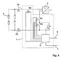
- Fig. 4Another variant will be in Fig. 4 illustrated. It is similar to the one in Fig. 1 , However, a third relay R3 is additionally connected in the DC (+) line so that both lines 10 or DC (+) and DC (-) are separated by at least one relay. As a result, galvanic isolation is achieved at both poles.
- the relay R3is preferably designed so that it can also carry the full load current. Since a shutdown of the full load current through the third relay R3 is not provided by the circuit, this can also be a small relay with only a low holding power.
Landscapes
- Engineering & Computer Science (AREA)
- Power Engineering (AREA)
- Keying Circuit Devices (AREA)
- Driving Mechanisms And Operating Circuits Of Arc-Extinguishing High-Tension Switches (AREA)
- Inverter Devices (AREA)
- Emergency Protection Circuit Devices (AREA)
- Protection Of Static Devices (AREA)
- Photovoltaic Devices (AREA)
- Supply And Distribution Of Alternating Current (AREA)
- Heat Treatment Of Steel (AREA)
- Fats And Perfumes (AREA)
- Distribution Board (AREA)
Abstract
Description
Translated fromGermanDie Erfindung betrifft eine Lasttrenner-Anordnüng zum An- und Abschalten eines DC-Stromes eines DC-Stromkreises in einer Photovoltaikanlage mit einem Halbleiter-Schaltelement zur Vermeidung eines Schaltlichtbogens.The invention relates to a load disconnect Anordnüng for switching on and off a DC current of a DC circuit in a photovoltaic system with a semiconductor switching element to avoid a switching arc.
Lasttrenner-Anordnungen zum Zu- und Abschalten eines DC-Stromes eines DC-Stromkreises in einer Photovoltaikanlage benötigen ein geeignetes Schaltmittel. Der von Sonnenenergie in Photovoltaikmodulen bzw. der in dem Solargenerator erzeugte DC-Strom, der beispielsweise von einem Wechselrichter in eine für ein Energieversorgungsnetz taugliche Wechselspannung umgewandelt wird, kann durch die Lasttrenner-Anordnung an den Wechselrichter weitergeleitet oder unterbrochen werden.Load breaker arrangements for connecting and disconnecting a DC current of a DC circuit in a photovoltaic system require suitable switching means. The DC power generated by solar energy in photovoltaic modules or in the solar generator, which is converted, for example, by an inverter into a suitable for a power grid AC voltage can be forwarded or interrupted by the load disconnector arrangement to the inverter.
Es sind DC-Relais bekannt, die durch Schaltkontakte einen Strom unterbrechen können. Das Relais umfasst eine Steuerspule, die von einem elektrischen Strom durchflossen wird, so dass ein Metallanker anzieht. Dieser Metallanker ist mechanisch mit einem oder mehreren elektrischen Hauptkontakten verbunden. Die Hauptkontakte werden durch eine Anziehbewegung des Ankers in Richtung der Steuerspule ein- oder ausgeschaltet, je nachdem ob das Relais als Öffner oder Schließer ausgeführt ist. Ein solches Relais ist im Prinzip ein elektrisch steuerbarer Schalter.There are known DC relays that can interrupt a current through switch contacts. The relay comprises a control coil through which an electric current flows, so that a metal armature attracts. This metal anchor is mechanically connected to one or more main electrical contacts. The main contacts are switched on or off by a tightening movement of the armature in the direction of the control coil, depending on whether the relay is designed as an opener or closer. Such a relay is in principle an electrically controllable switch.
Relais haben allerdings den Nachteil, dass Schaltlichtbögen, insbesondere beim Abschalten des DC-Stromes, entstehen. Dies führt kurzzeitig zu hohen Temperaturen und zu einem hohen Kontaktabbrand der Schaltkontakte. Dadurch können die Schaltkontakte leicht verschweißen, so dass sie praktisch verkleben und keine Stromunterbrechung mehr möglich ist. Dieses Phänomen ist unter dem Begriff "Kontaktschweißen" bekannt. Relais werden häufig für kleinere Ströme eingesetzt, die in der Regel 30 A nicht überschreiten.However, relays have the disadvantage that switching arcs, in particular when switching off the DC current arise. This leads briefly to high temperatures and high contact erosion of the switching contacts. As a result, the switch contacts can easily weld, so that they practically bond and no power interruption is possible. This phenomenon is known as contact welding. Relays are often used for smaller currents, which usually do not exceed 30 A.
Vergleichbare elektrisch steuerbare Schalter werden als Schütze bezeichnet. Sie sind im Vergleich zu Relais robuster ausgeführt und für höhere Ströme, zum Beispiel für bis zu mehreren 100 A, ausgelegt, wobei die Gefahr eines Kontaktverschweißens reduziert ist. Diese Gefahr lässt sich jedoch nicht gänzlich vermeiden. Die Schütze haben jedoch den Nachteil, dass sie relativ groß und auch teuer sind. Außerdem benötigen sie eine hohe Halteleistung für die Steuerspule. Nicht nur bei Photovoltaikanlagen ist man jedoch bestrebt, die erzeugte Energie so effektiv wie nur möglich einzusetzen.Comparable electrically controllable switches are referred to as contactors. They are designed to be more robust compared to relays and designed for higher currents, for example up to several 100 A, where the risk of contact welding is reduced. However, this danger can not be completely avoided. However, the shooters have the disadvantage that they are relatively large and also expensive. In addition, they require a high holding power for the control coil. However, it is not only photovoltaic systems that strive to use the energy generated as effectively as possible.
Relais und Schütze haben aber den Vorteil, dass sie optional mit anreihbaren Hilfsschaltern ausgestattet werden können, die zu Kontrollzwecken oder anderen Steuerungszwecken eingesetzt werden können. So kann zum Beispiel ein Hilfskreis geschaffen werden, der durch den Hilfsschalter eine Signallampe ansteuert, die einen Fehler, wie z. B. einen Kurzschluss, signalisiert.However, relays and contactors have the advantage that they can optionally be equipped with bayable auxiliary switches that can be used for control purposes or other control purposes. Thus, for example, an auxiliary circuit can be created, which drives a signal lamp through the auxiliary switch, which causes an error, such. B. a short circuit signaled.
Als weitere Schaltgeräte sind Lastschalter oder Sicherungsautomaten bekannt. Solche Geräte sind Sicherungen bzw. automatisch auslösende Schalter, die bei einem hohen Strom abschalten. Diese Geräte weisen häufig eine Überstrom- und eine Kurzschlussschutzfunktion auf. Die Überstromschutzfunktion wird meistens durch einen um eine Bimetallfeder gewickelten Draht realisiert, der die Feder bei hohem Strom verbiegt, so dass ein mit Schaltkontakten verbundener Auslösemechanismus betätigt wird. Diese Überstromschutzfunktion ist träge. Bei einem Kurzschluss bzw. sehr hohem Strom wirken dagegen sehr schnell elektromagnetische Kräfte auf den Auslösemechanismus und/oder den Schaltkontakten selbst, so dass ein schnelles Auftrennen der Schaltkontakte möglich ist. Um entstehende Schaltlichtbögen zu reduzieren, werden, wie auch teilweise bei Schützen, Löschbleche eingesetzt. So ist die Gefahr eines Kontaktverschweißens eher gering. Eine Steuerung der Schaltkontakte ist jedoch nur mit speziellen Fernsteuerungsmodulen möglich, die sehr teuer sind und nur für Geräte hoher Ströme bzw. Schaltleistungen angeboten werden. Soll eine Abschaltung aufgrund eines anderen Ereignisses, wie ein Öffnen eines Gehäusedeckels erfolgen, sind Lösungen mit solchen Geräten nur für hohe Ströme und nur mit sehr hohen Kosten und einem erheblichen Platzverbrauch realisierbar.As a further switching devices load switch or circuit breakers are known. Such devices are fuses or automatic tripping switches that turn off at a high current. These devices often have overcurrent and short-circuit protection. The overcurrent protection function is usually realized by a wire wound around a bimetallic spring, which bends the spring at high current, so that a tripping mechanism connected to switch contacts is actuated. This overcurrent protection function is slow. In the case of a short circuit or a very high current, on the other hand, electromagnetic forces very quickly act on the triggering mechanism and / or the switching contacts themselves, so that a quick separation of the switching contacts is possible. In order to reduce arcing faults, quenching plates are used, as is sometimes the case with contactors. So the risk of contact welding is rather low. However, a control of the switching contacts is possible only with special remote control modules, which are very expensive and are offered only for devices with high currents or switching performance. Should a shutdown due to another event, such as Open a housing cover done, solutions with such devices can only be realized for high currents and only with very high costs and considerable space consumption.
Bei Photovoltaikanlagen kommt noch hinzu, dass dort Kurzschlussströme aufgrund der solarzellentypischen Kennlinie in der Regel 20 bis 40 % höher als im Nennbetrieb sind. Bei derartigen Sicherungen ist aber ein 50% bis 100% höherer Strom erforderlich, damit die Kurzschlusssicherung anspricht. So wird im Kurzschlussfall ein DC-Strom nicht oder nur sehr spät abgeschaltet. Dies ist jedoch aus Sicherheitsgründen nicht akzeptabel.In the case of photovoltaic systems, short-circuit currents are usually 20 to 40% higher than in nominal operation due to the solar cell characteristic. With such fuses but a 50% to 100% higher current is required for the short-circuit protection responds. Thus, in the event of a short circuit, a DC current is not switched off or only very late. However, this is not acceptable for security reasons.
Außerdem ist der Abschaltstrom immer größer als der Nennstrom, wobei, je größer der Überstrom ist, desto schneller schaltet die Sicherung ab. Bei nur kleinen Strömen kann es zur Überhitzung der Sicherung kommen. Daher ist der Einsatz einer solchen Sicherung zum Schutz in Photovoltaikanlagen nur bedingt geeignet.In addition, the turn-off current is always greater than the rated current, with the larger the overcurrent, the faster the fuse will turn off. With only small currents, the fuse may overheat. Therefore, the use of such a fuse for protection in photovoltaic systems is only partially suitable.
Auch bekannt sind einfache Schmelzsicherungen. Ein solche Sicherung besteht aus einem in einem Gehäuse gekapselten Sicherungsdraht oder Streifenleiter, der an den Enden der Sicherung mit Kontaktelementen geführt und elektrisch verbunden ist. Das Gehäuse kann mit Luft, einem Gas oder anderen Füllmaterialien gefüllt sein. Fließt durch die Schmelzsicherung ein höherer Strom als der Nennstrom der Sicherung beträgt, dann schmilzt der Draht oder eingesetzte Leiter, so dass der Stromkreis unterbrochen wird.Also known are simple fuses. Such a fuse consists of an encapsulated in a housing fuse wire or strip conductor, which is guided at the ends of the fuse with contact elements and electrically connected. The housing may be filled with air, a gas or other filling materials. If a higher current flows through the fuse than the rated current of the fuse, then the wire or inserted conductor melts, so that the circuit is interrupted.
Solche Schmelzsicherungen sind kostengünstig und zum Schutz von Geräten und elektrischen Komponenten, wie Schaltungen oder Leitungen, sehr geeignet und sogar für sehr große Ströme, wie mehrere 100A, und Spannungen, wie mehrere 100V, verfügbar. Eine Schmelzsicherung ist aber nach dem Auslösen nicht wieder zu verwenden und muss ausgetauscht werden. Als auszulösendes Ereignis kann nur ein Überstrom betrachtet werden. Eine Stromunterbrechung aufgrund eines anderen Ereignisses ist nicht möglich.Such fuses are inexpensive and very suitable for protecting equipment and electrical components, such as circuits or lines, and are even available for very large currents, such as several 100A, and voltages, such as several 100V. But a fuse can not be used again after triggering and must be replaced. Only one overcurrent can be considered as an event to be triggered. A power interruption due to another event is not possible.
Auch bekannt sind mechanische DC-Schalter. Diese weisen ein von Hand betätigbares Bedienelement auf. Von außen ist dieses Bedienelement zugänglich, so dass es durch eine Bewegung, wie Drehbewegung, Ziehbewegung oder Schiebebewegung, in eine oder mehrere andere Positionen gebracht werden kann. Durch die manuelle Bewegung wird ein Kontaktmechanismus betätigt, der wiederum einen elektrischen Hauptkontakt betätigt. Ein solcher Schalter ist ein manuell betätigbarer Schalter mit mehreren Kontaktpositionen, die durch verschiedene Raststellungen des Bedienteiles erreicht werden können. Sie können mehrere Kontakte gleichzeitig schalten, um zum Beispiel mehrere Stromkreise gleichzeitig zu trennen. Auch sind sie für hohe Schaltströme und Spannungen, wie mehrere 100A und mehrere 100V, geeignet. Sie haben jedoch den Nachteil, dass sie einen großen Platzbedarf und Verdrahtungsaufwand erfordern. Außerdem sind sie nur manuell bedienbar und daher nicht für Schutzfunktionen, wie Überstrom, und nicht zum automatischen Auslösen bei anderen Ereignissen brauchbar.Also known are mechanical DC switches. These have a manually operable control element. From the outside of this control is accessible so that it can be brought by one movement, such as rotational movement, pulling movement or sliding movement in one or more other positions. The manual movement actuates a contact mechanism which in turn actuates a main electrical contact. Such a switch is a manually operable switch with multiple contact positions that can be achieved by different locking positions of the control panel. You can switch several contacts at the same time, for example, to separate several circuits at the same time. They are also suitable for high switching currents and voltages, such as several 100A and several 100V. However, they have the disadvantage that they require a lot of space and wiring. In addition, they are only manually operable and therefore not useful for protection functions, such as overcurrent, and not for automatically triggering other events.
Andere Stromunterbrechungseinrichtungen, die für Photovoltaikanlagen geeignet sind, sind unter dem Begriff "Electronic Solar Switch (ESS)" bekannt und in der
Der ESS ist in einer der beiden DC-Leitungen angeordnet. Wird ein mechanischer Schalter betätigt, dann schaltet ein parallel geschalteter Halbleiterschalter zu oder ab. Dadurch wird die Entstehung eines Lichtbogens verhindert bzw. reduziert. Der ESS ist also im Grunde ein manuell betätigbarer Schalter mit elektronischer Unterstützung zur Lichtbogenlöschung. Dieser ist an einem Photovoltaikwechselrichter angepasst und für einen Strom bis zu mehreren 10A und einer Spannung bis zu mehreren 100V geeignet. Ein solcher ESS ist nur manuell bedienbar.The ESS is located in one of the two DC lines. If a mechanical switch is actuated, a parallel-connected semiconductor switch switches on or off. This prevents or reduces the formation of an arc. The ESS is basically a manually operated switch with electronic support for Arc extinction. This is adapted to a photovoltaic inverter and suitable for a current up to several 10A and a voltage up to several 100V. Such an ESS is only manually operable.
Die
In der
Der Erfindung liegt die Aufgabe zugrunde, eine kostengünstige Lösung zu finden, mit der einerseits ein DC-Strom in einer Photovoltaikanlage sicher abzuschalten ist, und zwar nicht nur manuell sondern auch automatisch im Falle eines Fehlers, und andererseits eine galvanische Trennung in mindestens einer der zwei stromführenden Leitungen des DC-Stromkreises erzielt wird.The invention has for its object to find a cost-effective solution, on the one hand a DC power in a photovoltaic system is sure to turn off, not only manually but also automatically in case of failure, and on the other hand, a galvanic isolation in at least one of the two current-carrying lines of the DC circuit is achieved.
Diese Aufgabe wird erfindungsgemäß dadurch gelöst,
- dass eine elektronische Steuereinheit vorhanden ist, die derart ausgeführt ist, dass ein oder mehrere Signale von der Steuereinheit, insbesondere Signale, die Fehler im PV-Generator, Wechselrichter oder der AC-Seite empfangen werden, und dass ein oder mehrere Steuersignale an die Lasttrenner-Anordnung weitergegeben werden,
- dass ein Zu- oder Abschalten des DC-Stromkreises durch die Steuersignale automatisch bei mindestens einem bestimmten Ereignis, insbesondere bei einem Fehlerfall, erfolgt
- und dass die Lasttrenner-Anordnung so ausgeführt ist, dass in mindestens einer stromführenden Leitung des DC-Stromkreises im abgeschalteten Zustand eine galvanische Trennung durch einen automatisch durch die Steuereinheit steuerbaren Schaltkontakt. Insbesondere soll ein Halbleiter-Schaltelement den DC-Strom unterbrechen, so dass der Schaltkontakt stromlos geschaltet wird.
- an electronic control unit is provided which is designed such that one or more signals from the control unit, in particular signals, the faults in the PV generator, inverter or the AC side are received, and that one or more control signals are sent to the load breaker. Arrangement to be passed on
- in that the DC circuit is switched on or off automatically by the control signals in the case of at least one specific event, in particular in the case of an error
- and that the load disconnector arrangement is designed so that in at least one current-carrying line of the DC circuit in the off state, a galvanic isolation by an automatically controllable by the control unit switching contact. In particular, should a semiconductor switching element interrupt the DC current, so that the switching contact is de-energized.
Die Erfindung beruht auf dem Gedanken wenigstens einen, insbesondere mindestens zwei elektrisch steuerbare Schalter mit Schaltkontakten einzusetzen.The invention is based on the idea of using at least one, in particular at least two electrically controllable switches with switching contacts.
Durch die Erfindung können zum einen Relais eingesetzt werden, die durch die Steuersignale der erfindungsgemäßen Steuerungseinheit automatisch gesteuert werden, ohne dass die Gefahr eines Kontaktverschweißens entsteht. Der Strom wird erfindungsgemäß durch das Halbleiter-Schaltelement getrennt, so dass kein Schaltlichtbogen im Relais entstehen kann. Zudem wird ein für die galvanische Trennung eingesetztes Relais, insbesondere nur stromlos geschaltet. Dies hat den Vorteil, dass ein erheblich höherer Strom im Nennbetrieb durch das Relais fließen kann. Das Relais muss daher nicht überdimensioniert werden. Die Relais sind außerdem klein, kostengünstig und benötigen im Vergleich zu Schützen eine geringe Halteleistung. Grundsätzlich kann aber auch ein Schütz eingesetzt werden. Das Halbleiterschaltelement kann auch periodisch aus- und eingeschaltet werden, so dass beim Abschalten ein geringerer Strom im Schaltkontakt fließt und so kein Schaltlichtbogen entsteht. Durch das Takten kann insbesondere im Gleichspannungsnetz das Entstehen eines stabilen Lichtbogens verhindert werden.By means of the invention, relays can be used, for example, which are automatically controlled by the control signals of the control unit according to the invention without the risk of contact welding occurring. The current is separated according to the invention by the semiconductor switching element, so that no switching arc can arise in the relay. In addition, a relay used for galvanic isolation, in particular only switched off. This has the advantage that a considerably higher current can flow through the relay in rated operation. The relay must therefore not be oversized. The relays are also small, inexpensive and require a low holding power compared to contactors. In principle, however, a contactor can also be used. The semiconductor switching element can also be periodically switched off and on, so that when switching off a lower current flows in the switching contact and so no switching arc arises. By clocking the emergence of a stable arc can be prevented in particular in the DC voltage network.
Auch kann die Lasttrenner-Anordnung in einfacher Weise zum Zuschalten oder Abschalten bei anderen Ereignissen als Kurzschlussfehler eingesetzt werden, weil eine einfache Ansteuerung der Relais möglich ist.Also, the load breaker arrangement can be used in a simple manner for connecting or disconnecting in other events as a short circuit fault, because a simple control of the relay is possible.
Die Erfindung verbindet die Vorteile von ESS-Lösungen und eines automatisierten Abschaltens. So entsteht während des Schaltvorgangs kein bzw. lediglich ein reduzierter, ungefährlicher Lichtbogen und damit keine Gefährdung von Personen oder der Anlage, wobei im Fehlerfall an die Steuereinheit der Lasttrenner-Anordnung ein Signal übertragen werden kann.The invention combines the advantages of ESS solutions and automated shutdown. Thus, during the switching process no or only a reduced, non-hazardous arc and thus no risk to persons or the system, in the event of a fault to the control unit of the load disconnector arrangement, a signal can be transmitted.
Die Erfindung beruht weiterhin auf dem Gedanken, ein ESS-Bedienkonzept (
Zur Ausführung der Erfindung sind mindestens ein Relais, insbesondere zwei Relais oder mehr, zweckmäßig.At least one relay, in particular two relays or more, is expedient for carrying out the invention.
Durch das Verwenden von zwei Relais kann selbst bei Verschweißen einer der Kontakte eine galvanische Trennung aufrechterhalten werden.By using two relays, galvanic isolation can be maintained even when welding one of the contacts.
Die Steuereinheit kann zudem speziell auf Photovoltaikanlagen angepasste Auslösebedingungen bei Über- oder Kurzschlussströme ausführen. In der Steuereinheit kann beispielsweise ein Mikroprozessor eingesetzt werden. Vorzugsweise ist die Steuereinheit in der Lasttrenner-Anordnung integriert.In addition, the control unit can execute tripping conditions for overcurrent or short-circuit currents which are specially adapted to photovoltaic systems. In the control unit, for example, a microprocessor can be used. Preferably, the control unit is integrated in the load breaker arrangement.
Eine bevorzugte Ausführungsform der Erfindung zeichnet sich dadurch aus, dass in der stromführenden Leitung des DC-Stromkreises zwei nacheinander durch Steuersignale schaltbare Schaltmittel mit Schaltkontakten, insbesondere zwei Relais, derart angeordnet sind, dass zum einen eines der Schaltmittel von dem Halbleiter-Schaltelement überbrückt wird, so dass durch ein Öffnen des Halbleiter-Schaltelementes der DC-Strom abgeschaltet wird, und zum anderen die galvanische Trennung des DC-Stromkreises durch das andere Schaltmittel entsteht. Dadurch wird in zuverlässiger Weise verhindert, dass eine galvanische Trennung durch Kontaktverschweißen verhindert wird. Während das erste Relais durch das Halbleiter-Schaltelement überbrückt wird, kann dieser nahezu stromlos öffnen, weil der Strom beim Öffnen des Kontakts in den geschalteten Halbleiterschalter wechselt. Dadurch bildet sich zunächst kein Lichtbogen aus. Da in dem Halbleiterschalter kein Lichtbogen entstehen kann, kann so der Strom gefahrlos auf null reduziert werden. Das zweite zur galvanische Trennung vorgesehene Relais kann dann stromlos geschaltet werden.A preferred embodiment of the invention is characterized in that in the current-carrying line of the DC circuit two successively switchable by control signals switching means with switching contacts, in particular two relays, are arranged such that on the one hand one of the switching means is bridged by the semiconductor switching element, so that is switched off by opening the semiconductor switching element of the DC current, and on the other hand, the electrical isolation of the DC circuit is formed by the other switching means. This reliably prevents galvanic separation from being prevented by contact welding. While the first relay is bridged by the semiconductor switching element, it can open almost without power, because the current changes when opening the contact in the switched semiconductor switch. As a result, initially no arc forms. Since no arc can occur in the semiconductor switch, the current can be safely reduced to zero. The second provided for galvanic isolation relay can then be de-energized.
Eine optimale Ergänzung ist es, wenn ein zusätzlicher handbetätigbarer Lasttrenner, insbesondere ein ESS-Lasttrenner, angeschlossen wird. Durch das Entfernen eines Steckverbinders oder eines Schutzdeckels mit Lichtbogenschutzfunktion kann, unabhängig von Steuersignalen der Steuereinheit, der DC-Stromkreis manuell aufgetrennt werden.An optimal addition is when an additional hand-operated load disconnector, in particular an ESS load disconnector, is connected. By removing a connector or a protective cover with an arc protection function, the DC circuit can be disconnected manually, regardless of control unit control signals.
Um eine möglichst sichere Stromversorgung der Komponenten der Anordnung, d.h. Relais, Steuereinheit usw., zu gewährleisten, erfolgt mit Vorteil eine Spannungsversorgung der Lasttrenner-Anordnung sowohl von einer DC-Seite als auch von einer AC-Seite, so dass ebenfalls eine Redundanz vorliegt.To ensure the most reliable power supply to the components of the device, i. Relay, control unit, etc., takes place with advantage a power supply of the load breaker arrangement both from a DC side and from an AC side, so that there is also a redundancy.
Weitere vorteilhafte Ausgestaltungen der Erfindung sind aus den Unteransprüchen zu entnehmen.Further advantageous embodiments of the invention can be taken from the subclaims.
Anhand der Zeichnungen wird die Erfindung nachstehend beispielhaft näher erläutert. Es zeigen:
- Fig. 1
- eine erste Schaltung einer erfindungsgemäßen Lasttrenner-Anordnung;
- Fig. 2
- eine zweite Schaltung der erfindungsgemäßen Lasttrenner-Anordnung;
- Fig. 3
- eine dritte Schaltung der erfindungsgemäßen Lasttrenner-Anordnung;
- Fig. 4
- eine vierte Schaltung der erfindungsgemäßen Lasttrenner-Anordnung.
- Fig. 1
- a first circuit of a load breaker arrangement according to the invention;
- Fig. 2
- a second circuit of the load breaker arrangement according to the invention;
- Fig. 3
- a third circuit of the load breaker arrangement according to the invention;
- Fig. 4
- a fourth circuit of the load disconnector arrangement according to the invention.
Die Anordnung 1 liegt in einem DC-Stromkreis mit DC-Leitungen 10 zwischen einem Photovoltaikgenerator 2, einer Photovoltaikanlage und einem Wechselrichter 3 bzw. einem DC/AC-Umrichter. Ist der Photovoltaikgenerator 2 dem Wechselrichter 3 zugeschaltet, dann sind beide Relais R1, R2 geschlossen. Beide Relais sind so ausgelegt, dass sie im geschlossenen Zustand den erforderlichen Laststrom führen können.The
Weiterhin umfasst die Anordnung 1 eine elektronische Steuereinheit 5, die mit den Relais R1, R2 bzw. dessen Steuerspulen S1, S2 verbunden ist und so durch Steuersignale die Schaltkontakte K1, K2 automatisch betätigen kann. Zudem ist das Halbleiter-Schaltelement ebenfalls durch die Einheit 5 steuerbar.Furthermore, the
Soll die Verbindung zwischen dem Photovoltaikgenerator 2 und dem Wechselrichter 3 getrennt werden, wird zunächst das Halbleiter-Schaltelement 4 geschlossen. In einem zweiten Schritt wird das Relais R2 geöffnet, so dass der Laststrom durch die Reihenschaltung aus Relais R1 und dem Halbleiter-Schaltelement 4 fließt. In einem dritten Schritt wird das Schaltelement 4 geöffnet, so dass der volle Laststrom abgeschaltet werden kann, ohne dass ein Lichtbogen auftritt. Dadurch wird ein Lichtbogen verhindert. In einem vierten Schritt wird das Relais R1 geöffnet. Dadurch wird eine galvanische Trennung zwischen Generator 2 und Wechselrichter 3 realisiert. Da das Relais R1 stromlos öffnet, kann sich an seinem Kontakt K1 kein Lichtbogen ausbilden. Ein Zuschalten des DC-Stromes erfolgt in umgekehrter Reihenfolge.If the connection between the
Diese Schritte werden von der Steuereinheit 5 gesteuert, d.h. dass die Ansteuerung der Relais R1, R2 und des Schaltelements 4 über eine Steuerelektronik der Steuereinheit 5 erfolgt. Über eine Steuerleitung 6 kann ein Ereignissignal zum Zu- oder Abschalten gegeben werden.
Auszulösende Ereignisse können ein Überstrom, eine Überspannung, eine zu hohe Temperatur, ein Feuer in einem Gerät, ein Defekt eines Gerätes, ein manueller Abschaltbefehl, ein externer, elektrischer Befehl, eine Öffnung eines Gerätedeckels, ein Ausfall eines öffentlichen Niederspannungsnetzes und/oder ein Diebstahl der Photovoltaikanlage sein. Solche Ereignisse können über eine gesonderte Elektronik bzw. Sensorik erfasst werden.These steps are controlled by the
Events to be triggered may include overcurrent, overvoltage, excessive temperature, a fire in a device, a device malfunction, a manual shutdown command, an external electrical command, a device cover opening, a public low voltage network failure, and / or a theft be the photovoltaic system. Such events can be detected by separate electronics or sensors.
Eine Auswertung, ob ein Ereignis bzw. Fehlerfall vorliegt, kann entweder von der Steuereinheit 5 oder durch eine externe elektronische Einheit, insbesondere durch eine Einheit bzw. Elektronik im Wechselrichter 3, erfolgen. Bei beiden Varianten wird die Steuerleitung 6 genutzt. Alternativ können mehrere Steuerleitungen eingesetzt werden, um verschiedene Ereignis-Signale parallel übertragen zu können. Auch eine Ausführung der Leitung 6 als digitale Kommunikationsleitung oder Bus, beispielsweise RS232 oder CAN, ist möglich. Ebenfalls kann die Anordnung 1 über die Leitung 6 oder eine andere Steuer- und Kommunikationsleitung eine Meldung an eine weitere, externe elektronische Einheit weitergeben, um z.B. zu signalisieren, dass eine selbsttätige Abschaltung infolge eines Ereignisses erfolgt ist. Hierbei kann auch eine erkannte Fehlerursache über diese Leitung übertragen werden.An evaluation as to whether an event or error occurs is possible either by the
Weiterhin ist die Steuereinheit 5 mit einer Spannungsversorgungsleitung 7 versehen, die vorzugsweise redundant angeschlossen ist, indem ein Versorgungsanschluss sowohl auf der DC-Seite bzw. Photovoltaikseite als auch auf der AC-Seite bzw. Netzseite erfolgt.Furthermore, the
Das Relais R1 oder vorzugsweise beide Relais R1, R2 sind so ausgefegt, dass sie im geöffneten Zustand jeweils eine maximale Leerlaufspannung des DC-Stromkreises halten. Da die Relais R1, R2 nicht den Strom abschalten, können Relais mit geringerer Halteleistung eingesetzt werden. Ein direktes Abschalten des Laststromes würde nämlich wesentlich größere und robustere Relais mit hoher Halteleistung erfordern.The relay R1 or preferably both relays R1, R2 are so designed that in the open state they each hold a maximum no-load voltage of the DC circuit. Since the relays R1, R2 do not turn off the power, relays with lower holding power can be used. A direct shutdown of the load current would require much larger and more robust relay with high holding power.
Eine Variante der Schaltung ist in
Denkbar ist auch, auf das Relais R1 nach
Als ESS ist eine manuell trennbare, mit einer elektronischen Lichtbogenlöscheinrichtung versehene DC-Strom-Verbindungseinrichtung mit Steckkontakten für Photovoltaikanlagen zu verstehen.As ESS is a manually separable, provided with an electronic arc quenching DC power connection device with plug contacts for photovoltaic systems to understand.
Eine andere Variante der erfindungsgemäßen Schaltungs-Anordnung zeigt
Eine weitere Variante wird in
- 11
- Lasttrenner-AnordnungLoad breaker arrangement
- 22
- Photovoltaikgeneratorphotovoltaic generator
- 33
- Wechselrichterinverter
- 44
- HalbleiterschaltelementSemiconductor switching element
- 55
- Elektronische SteuereinheitElectronic control unit
- 66
- Steuerleitungcontrol line
- 77
- SpannungsversorgungsleitungPower Line
- 88th
- handbetätigbarer Lasttrennermanually operated load breaker
- 99
- --
- 1010
- DC-LeitungenDC cables
- R1, R2, R3R1, R2, R3
- Relaisrelay
- S1, S2S1, S2
- Steuerspulencontrol coils
- K1, K2K1, K2
- Schaltkontakteswitch contacts
Claims (12)
Translated fromGermandadurch gekennzeichnet,
characterized,
dadurch gekennzeichnet,
dass ein Halbleiter-Schaltelement (4) den DC-Strom unterbricht, so dass der Schaltkontakt stromlos geschaltet wird.Load breaker arrangement according to claim 1,
characterized,
that a semiconductor switching element (4) interrupts the DC current, so that the switching contact is de-energized.
dadurch gekennzeichnet,
dass in der stromführenden Leitung des DC-Stromkreises zwei nacheinander durch Steuersignale schaltbare Schaltmittel mit Schaltkontakten (K1, K2), insbesondere zwei Relais (R1, R2), derart angeordnet sind, dass zum einen eines der Schaltmittel von dem Halbleiter-Schaltelement (4) überbrückt wird, so dass durch ein Öffnen des Halbleiter-Schaltelementes (4) der DC-Strom abgeschaltet wird, und zum anderen die galvanische Trennung des DC-Stromkreises durch das andere Schaltmittel entsteht.Load breaker arrangement according to claim 1 or 2,
characterized,
that in the current-carrying line of the DC circuit two successively switchable by control signals switching means Switch contacts (K1, K2), in particular two relays (R1, R2), are arranged such that on the one hand, the switching means of the semiconductor switching element (4) is bridged, so that by opening the semiconductor switching element (4) of DC power is turned off, and on the other hand, the galvanic isolation of the DC circuit is formed by the other switching means.
dadurch gekennzeichnet,
dass eines der Schaltmittel in Reihe mit dem Halbleiter-Schaltelement (4) angeordnet ist.Load breaker arrangement according to claim 3,
characterized,
in that one of the switching means is arranged in series with the semiconductor switching element (4).
dadurch gekennzeichnet,
dass ein zusätzlicher handbetätigbarer Lasttrenner (8), insbesondere ein ESS-Lasttrenner, angeschlossen ist.Load breaker arrangement according to claim 2 or 3,
characterized,
that an additional hand-operated load disconnector (8), in particular an ESS load disconnector, is connected.
dadurch gekennzeichnet,
dass die Schaltkontakte der Schaltmittel in Reihe geschaltet sind.Load breaker arrangement according to one of claims 3 to 5,
characterized,
that the switching contacts of the switching means are connected in series.
dadurch gekennzeichnet,
dass ein drittes Schaltmittel mit Schaltkontakten (K1, K2) in einer anderen stromführenden Leitung des DC-Stromkreises angeschlossen ist.Load breaker arrangement according to one of claims 3 to 6,
characterized,
that a third switching means with switching contacts (K1, K2) is connected in another current-carrying line of the DC circuit.
gekennzeichnet durch
mindestens zwei Relais (R1, R2, R3).Load breaker arrangement according to one of the preceding claims,
marked by
at least two relays (R1, R2, R3).
dadurch gekennzeichnet,
dass das Ereignis
characterized,
that the event
dadurch gekennzeichnet,
dass eine externe Steuerleitüng (6) der Steuereinheit (5) vorhanden ist und die Steuereinheit (5) außerhalb der Lasttrenner-Anordnung (1) angeordnet ist, insbesondere in einem Solarwechselrichter angeordnet ist, oder dass die Steuereinheit (5), insbesondere eine Fehlererkennungseinheit, in eine Steuerelektronik der Lasttrenner-Anordnung (1) integriert ist.Load breaker arrangement according to one of the preceding claims,
characterized,
that an external Steuerleitüng (6) of the control unit (5) is present and the control unit (5) outside of the load breaker arrangement (1) is arranged, is arranged in particular in a solar inverter, or that the control unit (5), in particular a fault detection unit, is integrated in a control electronics of the load disconnector arrangement (1).
dadurch gekennzeichnet,
dass eine Spannungsversorgung der Lasttrenner-Anordnung sowohl von einer DC-Seite als auch von einer AC-Seite erfolgt.Load breaker arrangement according to one of the preceding claims,
characterized,
that a voltage supply of the load breaker arrangement occurs both from a DC side and from an AC side.
dadurch gekennzeichnet,
dass beim Abschalten
characterized,
that when switching off
Priority Applications (6)
| Application Number | Priority Date | Filing Date | Title |
|---|---|---|---|
| ES07019985TES2340079T3 (en) | 2007-10-12 | 2007-10-12 | PROVISION OF LOAD SECTIONERS. |
| AT07019985TATE463829T1 (en) | 2007-10-12 | 2007-10-12 | LOAD DISCONNECTOR ARRANGEMENT |
| EP07019985AEP2048679B1 (en) | 2007-10-12 | 2007-10-12 | Circuit breaker assembly |
| DE502007003419TDE502007003419D1 (en) | 2007-10-12 | 2007-10-12 | Load breaker arrangement |
| US12/286,429US8213133B2 (en) | 2007-10-12 | 2008-09-30 | Load breaker arrangement |
| KR1020080096361AKR101059585B1 (en) | 2007-10-12 | 2008-10-01 | Load switch |
Applications Claiming Priority (1)
| Application Number | Priority Date | Filing Date | Title |
|---|---|---|---|
| EP07019985AEP2048679B1 (en) | 2007-10-12 | 2007-10-12 | Circuit breaker assembly |
Publications (2)
| Publication Number | Publication Date |
|---|---|
| EP2048679A1true EP2048679A1 (en) | 2009-04-15 |
| EP2048679B1 EP2048679B1 (en) | 2010-04-07 |
Family
ID=39156595
Family Applications (1)
| Application Number | Title | Priority Date | Filing Date |
|---|---|---|---|
| EP07019985AActiveEP2048679B1 (en) | 2007-10-12 | 2007-10-12 | Circuit breaker assembly |
Country Status (6)
| Country | Link |
|---|---|
| US (1) | US8213133B2 (en) |
| EP (1) | EP2048679B1 (en) |
| KR (1) | KR101059585B1 (en) |
| AT (1) | ATE463829T1 (en) |
| DE (1) | DE502007003419D1 (en) |
| ES (1) | ES2340079T3 (en) |
Cited By (73)
| Publication number | Priority date | Publication date | Assignee | Title |
|---|---|---|---|---|
| DE102010007452A1 (en)* | 2010-02-10 | 2011-08-11 | Siemens Aktiengesellschaft, 80333 | Switching relief for a circuit breaker |
| WO2012040760A2 (en) | 2010-09-30 | 2012-04-05 | Fronius International Gmbh | Inverter and method for isolating photovoltaic modules from an inverter |
| US20120187089A1 (en)* | 2008-10-27 | 2012-07-26 | Xuanshu Chen | High-voltage, super-voltage and heavy current breaker |
| DE102011076553A1 (en)* | 2011-05-26 | 2012-11-29 | Solarworld Ag | CONTROL OF THE DC FLOW OF A PHOTOVOLTAIC SYSTEM |
| EP2293345A3 (en)* | 2009-08-05 | 2012-12-26 | Adensis GmbH | Pyro fuse with varistor control for separating an inverter from a photovoltaic assembly |
| US8570005B2 (en) | 2011-09-12 | 2013-10-29 | Solaredge Technologies Ltd. | Direct current link circuit |
| US8587151B2 (en) | 2006-12-06 | 2013-11-19 | Solaredge, Ltd. | Method for distributed power harvesting using DC power sources |
| US8599588B2 (en) | 2007-12-05 | 2013-12-03 | Solaredge Ltd. | Parallel connected inverters |
| US8659188B2 (en) | 2006-12-06 | 2014-02-25 | Solaredge Technologies Ltd. | Distributed power harvesting systems using DC power sources |
| WO2014048716A1 (en)* | 2012-09-25 | 2014-04-03 | Siemens Aktiengesellschaft | Disconnecting assembly for a high-voltage direct-current network |
| WO2013037740A3 (en)* | 2011-09-12 | 2014-04-10 | Sma Solar Technology Ag | Safety device for a photovoltaic system |
| US8710699B2 (en) | 2009-12-01 | 2014-04-29 | Solaredge Technologies Ltd. | Dual use photovoltaic system |
| EP2315328A3 (en)* | 2009-10-20 | 2014-04-30 | Eaton Corporation | String and system employing direct current electrical generating modules and a number of string protectors |
| US8766696B2 (en) | 2010-01-27 | 2014-07-01 | Solaredge Technologies Ltd. | Fast voltage level shifter circuit |
| US8773092B2 (en) | 2007-08-06 | 2014-07-08 | Solaredge Technologies Ltd. | Digital average input current control in power converter |
| US8957645B2 (en) | 2008-03-24 | 2015-02-17 | Solaredge Technologies Ltd. | Zero voltage switching |
| US8988838B2 (en) | 2012-01-30 | 2015-03-24 | Solaredge Technologies Ltd. | Photovoltaic panel circuitry |
| US9006569B2 (en) | 2009-05-22 | 2015-04-14 | Solaredge Technologies Ltd. | Electrically isolated heat dissipating junction box |
| US9041339B2 (en) | 2006-12-06 | 2015-05-26 | Solaredge Technologies Ltd. | Battery power delivery module |
| CN104685749A (en)* | 2012-10-01 | 2015-06-03 | 罗伯特·博世有限公司 | Circuit configuration with an inverter |
| US9130401B2 (en) | 2006-12-06 | 2015-09-08 | Solaredge Technologies Ltd. | Distributed power harvesting systems using DC power sources |
| US9235228B2 (en) | 2012-03-05 | 2016-01-12 | Solaredge Technologies Ltd. | Direct current link circuit |
| US9318974B2 (en) | 2014-03-26 | 2016-04-19 | Solaredge Technologies Ltd. | Multi-level inverter with flying capacitor topology |
| US9362743B2 (en) | 2008-05-05 | 2016-06-07 | Solaredge Technologies Ltd. | Direct current power combiner |
| US9368964B2 (en) | 2006-12-06 | 2016-06-14 | Solaredge Technologies Ltd. | Distributed power system using direct current power sources |
| US9537445B2 (en) | 2008-12-04 | 2017-01-03 | Solaredge Technologies Ltd. | Testing of a photovoltaic panel |
| US9543889B2 (en) | 2006-12-06 | 2017-01-10 | Solaredge Technologies Ltd. | Distributed power harvesting systems using DC power sources |
| US9548619B2 (en) | 2013-03-14 | 2017-01-17 | Solaredge Technologies Ltd. | Method and apparatus for storing and depleting energy |
| US9590526B2 (en) | 2006-12-06 | 2017-03-07 | Solaredge Technologies Ltd. | Safety mechanisms, wake up and shutdown methods in distributed power installations |
| US9647442B2 (en) | 2010-11-09 | 2017-05-09 | Solaredge Technologies Ltd. | Arc detection and prevention in a power generation system |
| US9644993B2 (en) | 2006-12-06 | 2017-05-09 | Solaredge Technologies Ltd. | Monitoring of distributed power harvesting systems using DC power sources |
| US9812984B2 (en) | 2012-01-30 | 2017-11-07 | Solaredge Technologies Ltd. | Maximizing power in a photovoltaic distributed power system |
| US9819178B2 (en) | 2013-03-15 | 2017-11-14 | Solaredge Technologies Ltd. | Bypass mechanism |
| US9831824B2 (en) | 2007-12-05 | 2017-11-28 | SolareEdge Technologies Ltd. | Current sensing on a MOSFET |
| US9853565B2 (en) | 2012-01-30 | 2017-12-26 | Solaredge Technologies Ltd. | Maximized power in a photovoltaic distributed power system |
| US9866098B2 (en) | 2011-01-12 | 2018-01-09 | Solaredge Technologies Ltd. | Serially connected inverters |
| US9870016B2 (en) | 2012-05-25 | 2018-01-16 | Solaredge Technologies Ltd. | Circuit for interconnected direct current power sources |
| US9869701B2 (en) | 2009-05-26 | 2018-01-16 | Solaredge Technologies Ltd. | Theft detection and prevention in a power generation system |
| US9935458B2 (en) | 2010-12-09 | 2018-04-03 | Solaredge Technologies Ltd. | Disconnection of a string carrying direct current power |
| US9941813B2 (en) | 2013-03-14 | 2018-04-10 | Solaredge Technologies Ltd. | High frequency multi-level inverter |
| US9960667B2 (en) | 2006-12-06 | 2018-05-01 | Solaredge Technologies Ltd. | System and method for protection during inverter shutdown in distributed power installations |
| US9960731B2 (en) | 2006-12-06 | 2018-05-01 | Solaredge Technologies Ltd. | Pairing of components in a direct current distributed power generation system |
| EP3300237A4 (en)* | 2015-05-20 | 2018-05-16 | Nissan Motor Co., Ltd. | Power supply control device and power supply control method |
| US10061957B2 (en) | 2016-03-03 | 2018-08-28 | Solaredge Technologies Ltd. | Methods for mapping power generation installations |
| US10115841B2 (en) | 2012-06-04 | 2018-10-30 | Solaredge Technologies Ltd. | Integrated photovoltaic panel circuitry |
| US10230310B2 (en) | 2016-04-05 | 2019-03-12 | Solaredge Technologies Ltd | Safety switch for photovoltaic systems |
| US10348094B2 (en) | 2015-01-28 | 2019-07-09 | Abb Schweiz Ag | Energy panel arrangement shutdown |
| US10404060B2 (en) | 2015-02-22 | 2019-09-03 | Abb Schweiz Ag | Photovoltaic string reverse polarity detection |
| US10599113B2 (en) | 2016-03-03 | 2020-03-24 | Solaredge Technologies Ltd. | Apparatus and method for determining an order of power devices in power generation systems |
| US10673222B2 (en) | 2010-11-09 | 2020-06-02 | Solaredge Technologies Ltd. | Arc detection and prevention in a power generation system |
| US10673229B2 (en) | 2010-11-09 | 2020-06-02 | Solaredge Technologies Ltd. | Arc detection and prevention in a power generation system |
| EP3281216B1 (en) | 2015-04-09 | 2020-06-24 | Harting Electric GmbH & Co. KG | Junction box and network for distributing energy |
| CN112271699A (en)* | 2020-10-14 | 2021-01-26 | 上能电气股份有限公司 | A photovoltaic inverter protection circuit |
| US10931119B2 (en) | 2012-01-11 | 2021-02-23 | Solaredge Technologies Ltd. | Photovoltaic module |
| CN112437966A (en)* | 2018-07-31 | 2021-03-02 | 松下知识产权经营株式会社 | Control system and circuit breaking system |
| CN112564047A (en)* | 2020-12-03 | 2021-03-26 | 爱士惟新能源技术(扬中)有限公司 | Input protection device and method of photovoltaic inverter and photovoltaic inverter system |
| US11018623B2 (en) | 2016-04-05 | 2021-05-25 | Solaredge Technologies Ltd. | Safety switch for photovoltaic systems |
| US11081608B2 (en) | 2016-03-03 | 2021-08-03 | Solaredge Technologies Ltd. | Apparatus and method for determining an order of power devices in power generation systems |
| US11177663B2 (en) | 2016-04-05 | 2021-11-16 | Solaredge Technologies Ltd. | Chain of power devices |
| US11264947B2 (en) | 2007-12-05 | 2022-03-01 | Solaredge Technologies Ltd. | Testing of a photovoltaic panel |
| US11296650B2 (en) | 2006-12-06 | 2022-04-05 | Solaredge Technologies Ltd. | System and method for protection during inverter shutdown in distributed power installations |
| US11309832B2 (en) | 2006-12-06 | 2022-04-19 | Solaredge Technologies Ltd. | Distributed power harvesting systems using DC power sources |
| WO2022233413A1 (en)* | 2021-05-06 | 2022-11-10 | Siemens Energy Global GmbH & Co. KG | Direct-current switching device |
| US11569660B2 (en) | 2006-12-06 | 2023-01-31 | Solaredge Technologies Ltd. | Distributed power harvesting systems using DC power sources |
| US11569659B2 (en) | 2006-12-06 | 2023-01-31 | Solaredge Technologies Ltd. | Distributed power harvesting systems using DC power sources |
| US11687112B2 (en) | 2006-12-06 | 2023-06-27 | Solaredge Technologies Ltd. | Distributed power harvesting systems using DC power sources |
| US11728768B2 (en) | 2006-12-06 | 2023-08-15 | Solaredge Technologies Ltd. | Pairing of components in a direct current distributed power generation system |
| US11735910B2 (en) | 2006-12-06 | 2023-08-22 | Solaredge Technologies Ltd. | Distributed power system using direct current power sources |
| US11855231B2 (en) | 2006-12-06 | 2023-12-26 | Solaredge Technologies Ltd. | Distributed power harvesting systems using DC power sources |
| US11881814B2 (en) | 2005-12-05 | 2024-01-23 | Solaredge Technologies Ltd. | Testing of a photovoltaic panel |
| US11888387B2 (en) | 2006-12-06 | 2024-01-30 | Solaredge Technologies Ltd. | Safety mechanisms, wake up and shutdown methods in distributed power installations |
| US12057807B2 (en) | 2016-04-05 | 2024-08-06 | Solaredge Technologies Ltd. | Chain of power devices |
| US12418177B2 (en) | 2009-10-24 | 2025-09-16 | Solaredge Technologies Ltd. | Distributed power system using direct current power sources |
Families Citing this family (19)
| Publication number | Priority date | Publication date | Assignee | Title |
|---|---|---|---|---|
| US9291696B2 (en) | 2007-12-05 | 2016-03-22 | Solaredge Technologies Ltd. | Photovoltaic system power tracking method |
| EP2225778B1 (en) | 2007-12-05 | 2019-06-26 | Solaredge Technologies Ltd. | Testing of a photovoltaic panel |
| FR2940459B1 (en)* | 2008-12-22 | 2012-11-30 | Commissariat Energie Atomique | METHOD FOR DETECTING ELECTRIC ARC IN A PHOTOVOLTAIC INSTALLATION |
| CA2758815A1 (en) | 2009-07-23 | 2011-01-27 | Enphase Energy, Inc. | Method and apparatus for detection and control of dc arc faults |
| US8350414B2 (en) | 2010-08-11 | 2013-01-08 | Xantrex Technology Inc. | Semiconductor assisted DC load break contactor |
| BR112013006956B1 (en)* | 2010-09-24 | 2020-04-22 | Siemens Ag | undersea power switching device and methods of operation thereof |
| DE102011015449B4 (en)* | 2011-01-25 | 2014-09-25 | Ellenberger & Poensgen Gmbh | Switching unit for switching high DC voltages |
| ITMI20110982A1 (en)* | 2011-05-30 | 2012-12-01 | Energy Engineering S R L | SAFETY DEVICE FOR A PHOTOVOLTAIC SYSTEM |
| US8619396B2 (en)* | 2011-06-24 | 2013-12-31 | Renewable Power Conversion, Inc. | Renewable one-time load break contactor |
| US20140062206A1 (en)* | 2012-08-29 | 2014-03-06 | Robert L. Bryson | Low Voltage Solar Electric Energy Distribution |
| ITTV20130015A1 (en)* | 2013-02-08 | 2014-08-09 | Ergos S R L | METHOD AND AUTOMATIC SYSTEM OF CURRENT INTERRUPTION CONFIGURED TO ISOLATE ELECTRICALLY, IN A SELECTIVE WAY, OF PHOTOVOLTAIC PANELS IN A STRING OF PHOTOVOLTAIC PANELS |
| JP6299507B2 (en)* | 2014-07-29 | 2018-03-28 | オムロン株式会社 | Protection device for solar power generation system and protection method for solar power generation system |
| AU2015364718B2 (en) | 2014-12-16 | 2019-11-28 | Marici Holdings The Netherlands B.V. | Energy panel arrangement power dissipation |
| KR101898587B1 (en)* | 2016-05-04 | 2018-09-13 | 엘지전자 주식회사 | Photovoltaic module and photovoltaic system including the same |
| CN107769242A (en) | 2016-08-23 | 2018-03-06 | 台达电子企业管理(上海)有限公司 | Photovoltaic generating system and its cut-off method |
| CN115473211A (en)* | 2016-09-12 | 2022-12-13 | 菲尼克斯电气公司 | DC Generator, DC Hybrid Switching Mechanism, Application and Method |
| KR102287066B1 (en)* | 2020-10-15 | 2021-08-09 | 주식회사 주왕산업 | Solar inverter system preventing the switching arc whe opening and closing contacts |
| JP2023122452A (en)* | 2022-02-22 | 2023-09-01 | オムロン株式会社 | Photovoltaic power generation system |
| WO2024102324A1 (en)* | 2022-11-11 | 2024-05-16 | Enphase Energy, Inc. | Arc-free hybrid relay |
Citations (8)
| Publication number | Priority date | Publication date | Assignee | Title |
|---|---|---|---|---|
| GB2049326A (en)* | 1979-04-14 | 1980-12-17 | Ch Polt I | Device for switching D-C circuits |
| US5633540A (en) | 1996-06-25 | 1997-05-27 | Lutron Electronics Co., Inc. | Surge-resistant relay switching circuit |
| US20020171983A1 (en)* | 2001-05-18 | 2002-11-21 | Vernon Brooks | Arc suppressing circuit employing a triggerable electronic switch to protect switch contacts |
| DE10225259B3 (en) | 2002-06-07 | 2004-01-22 | Sma Regelsysteme Gmbh | Electrical connector |
| US6741435B1 (en)* | 2000-08-09 | 2004-05-25 | Server Technology, Inc. | Power controller with DC ARC-supression relays |
| JP2005019107A (en)* | 2003-06-24 | 2005-01-20 | Sumitomo Electric Ind Ltd | DC relay |
| DE102004054933B3 (en) | 2004-11-13 | 2006-05-04 | Sma Technologie Ag | Protection device for a load current leading device |
| WO2007073951A1 (en) | 2005-12-22 | 2007-07-05 | SIEMENS AKTIENGESELLSCHAFT öSTERREICH | Load isolation circuit for the deenergized connection and isolation of electrical contacts |
Family Cites Families (4)
| Publication number | Priority date | Publication date | Assignee | Title |
|---|---|---|---|---|
| US6768621B2 (en)* | 2002-01-18 | 2004-07-27 | Solectria Corporation | Contactor feedback and precharge/discharge circuit |
| AU2003247484A1 (en)* | 2002-06-04 | 2003-12-19 | Sure Power Corporation | Load break dc power disconnect |
| US7110225B1 (en)* | 2005-03-31 | 2006-09-19 | Leviton Manufacturing Co., Inc. | Arc-limiting switching circuit |
| EP1858148A4 (en)* | 2006-02-24 | 2009-04-08 | Mitsubishi Electric Corp | COOPERATIVE SYSTEM INVERTER |
- 2007
- 2007-10-12DEDE502007003419Tpatent/DE502007003419D1/enactiveActive
- 2007-10-12ATAT07019985Tpatent/ATE463829T1/enactive
- 2007-10-12ESES07019985Tpatent/ES2340079T3/enactiveActive
- 2007-10-12EPEP07019985Apatent/EP2048679B1/enactiveActive
- 2008
- 2008-09-30USUS12/286,429patent/US8213133B2/enactiveActive
- 2008-10-01KRKR1020080096361Apatent/KR101059585B1/enactiveActive
Patent Citations (8)
| Publication number | Priority date | Publication date | Assignee | Title |
|---|---|---|---|---|
| GB2049326A (en)* | 1979-04-14 | 1980-12-17 | Ch Polt I | Device for switching D-C circuits |
| US5633540A (en) | 1996-06-25 | 1997-05-27 | Lutron Electronics Co., Inc. | Surge-resistant relay switching circuit |
| US6741435B1 (en)* | 2000-08-09 | 2004-05-25 | Server Technology, Inc. | Power controller with DC ARC-supression relays |
| US20020171983A1 (en)* | 2001-05-18 | 2002-11-21 | Vernon Brooks | Arc suppressing circuit employing a triggerable electronic switch to protect switch contacts |
| DE10225259B3 (en) | 2002-06-07 | 2004-01-22 | Sma Regelsysteme Gmbh | Electrical connector |
| JP2005019107A (en)* | 2003-06-24 | 2005-01-20 | Sumitomo Electric Ind Ltd | DC relay |
| DE102004054933B3 (en) | 2004-11-13 | 2006-05-04 | Sma Technologie Ag | Protection device for a load current leading device |
| WO2007073951A1 (en) | 2005-12-22 | 2007-07-05 | SIEMENS AKTIENGESELLSCHAFT öSTERREICH | Load isolation circuit for the deenergized connection and isolation of electrical contacts |
Cited By (204)
| Publication number | Priority date | Publication date | Assignee | Title |
|---|---|---|---|---|
| US11881814B2 (en) | 2005-12-05 | 2024-01-23 | Solaredge Technologies Ltd. | Testing of a photovoltaic panel |
| US11043820B2 (en) | 2006-12-06 | 2021-06-22 | Solaredge Technologies Ltd. | Battery power delivery module |
| US11594881B2 (en) | 2006-12-06 | 2023-02-28 | Solaredge Technologies Ltd. | Distributed power harvesting systems using DC power sources |
| US12388492B2 (en) | 2006-12-06 | 2025-08-12 | Solaredge Technologies Ltd. | Safety mechanisms, wake up and shutdown methods in distributed power installations |
| US11063440B2 (en) | 2006-12-06 | 2021-07-13 | Solaredge Technologies Ltd. | Method for distributed power harvesting using DC power sources |
| US12316274B2 (en) | 2006-12-06 | 2025-05-27 | Solaredge Technologies Ltd. | Pairing of components in a direct current distributed power generation system |
| US8587151B2 (en) | 2006-12-06 | 2013-11-19 | Solaredge, Ltd. | Method for distributed power harvesting using DC power sources |
| US11073543B2 (en) | 2006-12-06 | 2021-07-27 | Solaredge Technologies Ltd. | Monitoring of distributed power harvesting systems using DC power sources |
| US8659188B2 (en) | 2006-12-06 | 2014-02-25 | Solaredge Technologies Ltd. | Distributed power harvesting systems using DC power sources |
| US11183922B2 (en) | 2006-12-06 | 2021-11-23 | Solaredge Technologies Ltd. | Distributed power harvesting systems using DC power sources |
| US11296650B2 (en) | 2006-12-06 | 2022-04-05 | Solaredge Technologies Ltd. | System and method for protection during inverter shutdown in distributed power installations |
| US11309832B2 (en) | 2006-12-06 | 2022-04-19 | Solaredge Technologies Ltd. | Distributed power harvesting systems using DC power sources |
| US11476799B2 (en) | 2006-12-06 | 2022-10-18 | Solaredge Technologies Ltd. | Distributed power harvesting systems using DC power sources |
| US12281919B2 (en) | 2006-12-06 | 2025-04-22 | Solaredge Technologies Ltd. | Monitoring of distributed power harvesting systems using DC power sources |
| US11569660B2 (en) | 2006-12-06 | 2023-01-31 | Solaredge Technologies Ltd. | Distributed power harvesting systems using DC power sources |
| US10673253B2 (en) | 2006-12-06 | 2020-06-02 | Solaredge Technologies Ltd. | Battery power delivery module |
| US12276997B2 (en) | 2006-12-06 | 2025-04-15 | Solaredge Technologies Ltd. | Distributed power harvesting systems using DC power sources |
| US11569659B2 (en) | 2006-12-06 | 2023-01-31 | Solaredge Technologies Ltd. | Distributed power harvesting systems using DC power sources |
| US9041339B2 (en) | 2006-12-06 | 2015-05-26 | Solaredge Technologies Ltd. | Battery power delivery module |
| US12224706B2 (en) | 2006-12-06 | 2025-02-11 | Solaredge Technologies Ltd. | Pairing of components in a direct current distributed power generation system |
| US9130401B2 (en) | 2006-12-06 | 2015-09-08 | Solaredge Technologies Ltd. | Distributed power harvesting systems using DC power sources |
| US11575261B2 (en) | 2006-12-06 | 2023-02-07 | Solaredge Technologies Ltd. | Distributed power harvesting systems using DC power sources |
| US12107417B2 (en) | 2006-12-06 | 2024-10-01 | Solaredge Technologies Ltd. | Distributed power harvesting systems using DC power sources |
| US11575260B2 (en) | 2006-12-06 | 2023-02-07 | Solaredge Technologies Ltd. | Distributed power harvesting systems using DC power sources |
| US10637393B2 (en) | 2006-12-06 | 2020-04-28 | Solaredge Technologies Ltd. | Distributed power harvesting systems using DC power sources |
| US11579235B2 (en) | 2006-12-06 | 2023-02-14 | Solaredge Technologies Ltd. | Safety mechanisms, wake up and shutdown methods in distributed power installations |
| US9368964B2 (en) | 2006-12-06 | 2016-06-14 | Solaredge Technologies Ltd. | Distributed power system using direct current power sources |
| US11594882B2 (en) | 2006-12-06 | 2023-02-28 | Solaredge Technologies Ltd. | Distributed power harvesting systems using DC power sources |
| US9966766B2 (en) | 2006-12-06 | 2018-05-08 | Solaredge Technologies Ltd. | Battery power delivery module |
| US11002774B2 (en) | 2006-12-06 | 2021-05-11 | Solaredge Technologies Ltd. | Monitoring of distributed power harvesting systems using DC power sources |
| US10447150B2 (en) | 2006-12-06 | 2019-10-15 | Solaredge Technologies Ltd. | Distributed power harvesting systems using DC power sources |
| US9543889B2 (en) | 2006-12-06 | 2017-01-10 | Solaredge Technologies Ltd. | Distributed power harvesting systems using DC power sources |
| US9590526B2 (en) | 2006-12-06 | 2017-03-07 | Solaredge Technologies Ltd. | Safety mechanisms, wake up and shutdown methods in distributed power installations |
| US12046940B2 (en) | 2006-12-06 | 2024-07-23 | Solaredge Technologies Ltd. | Battery power control |
| US12032080B2 (en) | 2006-12-06 | 2024-07-09 | Solaredge Technologies Ltd. | Safety mechanisms, wake up and shutdown methods in distributed power installations |
| US9644993B2 (en) | 2006-12-06 | 2017-05-09 | Solaredge Technologies Ltd. | Monitoring of distributed power harvesting systems using DC power sources |
| US11594880B2 (en) | 2006-12-06 | 2023-02-28 | Solaredge Technologies Ltd. | Distributed power harvesting systems using DC power sources |
| US9680304B2 (en) | 2006-12-06 | 2017-06-13 | Solaredge Technologies Ltd. | Method for distributed power harvesting using DC power sources |
| US12068599B2 (en) | 2006-12-06 | 2024-08-20 | Solaredge Technologies Ltd. | System and method for protection during inverter shutdown in distributed power installations |
| US11598652B2 (en) | 2006-12-06 | 2023-03-07 | Solaredge Technologies Ltd. | Monitoring of distributed power harvesting systems using DC power sources |
| US12027970B2 (en) | 2006-12-06 | 2024-07-02 | Solaredge Technologies Ltd. | Safety mechanisms, wake up and shutdown methods in distributed power installations |
| US12027849B2 (en) | 2006-12-06 | 2024-07-02 | Solaredge Technologies Ltd. | Distributed power system using direct current power sources |
| US11658482B2 (en) | 2006-12-06 | 2023-05-23 | Solaredge Technologies Ltd. | Distributed power harvesting systems using DC power sources |
| US11961922B2 (en) | 2006-12-06 | 2024-04-16 | Solaredge Technologies Ltd. | Distributed power harvesting systems using DC power sources |
| US11682918B2 (en) | 2006-12-06 | 2023-06-20 | Solaredge Technologies Ltd. | Battery power delivery module |
| US9853490B2 (en) | 2006-12-06 | 2017-12-26 | Solaredge Technologies Ltd. | Distributed power system using direct current power sources |
| US11962243B2 (en) | 2006-12-06 | 2024-04-16 | Solaredge Technologies Ltd. | Method for distributed power harvesting using DC power sources |
| US10230245B2 (en) | 2006-12-06 | 2019-03-12 | Solaredge Technologies Ltd | Battery power delivery module |
| US11888387B2 (en) | 2006-12-06 | 2024-01-30 | Solaredge Technologies Ltd. | Safety mechanisms, wake up and shutdown methods in distributed power installations |
| US11687112B2 (en) | 2006-12-06 | 2023-06-27 | Solaredge Technologies Ltd. | Distributed power harvesting systems using DC power sources |
| US10097007B2 (en) | 2006-12-06 | 2018-10-09 | Solaredge Technologies Ltd. | Method for distributed power harvesting using DC power sources |
| US11031861B2 (en) | 2006-12-06 | 2021-06-08 | Solaredge Technologies Ltd. | System and method for protection during inverter shutdown in distributed power installations |
| US11728768B2 (en) | 2006-12-06 | 2023-08-15 | Solaredge Technologies Ltd. | Pairing of components in a direct current distributed power generation system |
| US11855231B2 (en) | 2006-12-06 | 2023-12-26 | Solaredge Technologies Ltd. | Distributed power harvesting systems using DC power sources |
| US11735910B2 (en) | 2006-12-06 | 2023-08-22 | Solaredge Technologies Ltd. | Distributed power system using direct current power sources |
| US9948233B2 (en) | 2006-12-06 | 2018-04-17 | Solaredge Technologies Ltd. | Distributed power harvesting systems using DC power sources |
| US9960667B2 (en) | 2006-12-06 | 2018-05-01 | Solaredge Technologies Ltd. | System and method for protection during inverter shutdown in distributed power installations |
| US9960731B2 (en) | 2006-12-06 | 2018-05-01 | Solaredge Technologies Ltd. | Pairing of components in a direct current distributed power generation system |
| US11594968B2 (en) | 2007-08-06 | 2023-02-28 | Solaredge Technologies Ltd. | Digital average input current control in power converter |
| US10116217B2 (en) | 2007-08-06 | 2018-10-30 | Solaredge Technologies Ltd. | Digital average input current control in power converter |
| US8773092B2 (en) | 2007-08-06 | 2014-07-08 | Solaredge Technologies Ltd. | Digital average input current control in power converter |
| US10516336B2 (en) | 2007-08-06 | 2019-12-24 | Solaredge Technologies Ltd. | Digital average input current control in power converter |
| US9673711B2 (en) | 2007-08-06 | 2017-06-06 | Solaredge Technologies Ltd. | Digital average input current control in power converter |
| US9853538B2 (en) | 2007-12-04 | 2017-12-26 | Solaredge Technologies Ltd. | Distributed power harvesting systems using DC power sources |
| US11264947B2 (en) | 2007-12-05 | 2022-03-01 | Solaredge Technologies Ltd. | Testing of a photovoltaic panel |
| US12055647B2 (en) | 2007-12-05 | 2024-08-06 | Solaredge Technologies Ltd. | Parallel connected inverters |
| US11183923B2 (en) | 2007-12-05 | 2021-11-23 | Solaredge Technologies Ltd. | Parallel connected inverters |
| US11894806B2 (en) | 2007-12-05 | 2024-02-06 | Solaredge Technologies Ltd. | Testing of a photovoltaic panel |
| US10644589B2 (en) | 2007-12-05 | 2020-05-05 | Solaredge Technologies Ltd. | Parallel connected inverters |
| US11183969B2 (en) | 2007-12-05 | 2021-11-23 | Solaredge Technologies Ltd. | Testing of a photovoltaic panel |
| US9831824B2 (en) | 2007-12-05 | 2017-11-28 | SolareEdge Technologies Ltd. | Current sensing on a MOSFET |
| US9979280B2 (en) | 2007-12-05 | 2018-05-22 | Solaredge Technologies Ltd. | Parallel connected inverters |
| US9407161B2 (en) | 2007-12-05 | 2016-08-02 | Solaredge Technologies Ltd. | Parallel connected inverters |
| US11693080B2 (en) | 2007-12-05 | 2023-07-04 | Solaredge Technologies Ltd. | Parallel connected inverters |
| US10693415B2 (en) | 2007-12-05 | 2020-06-23 | Solaredge Technologies Ltd. | Testing of a photovoltaic panel |
| US8599588B2 (en) | 2007-12-05 | 2013-12-03 | Solaredge Ltd. | Parallel connected inverters |
| US9876430B2 (en) | 2008-03-24 | 2018-01-23 | Solaredge Technologies Ltd. | Zero voltage switching |
| US8957645B2 (en) | 2008-03-24 | 2015-02-17 | Solaredge Technologies Ltd. | Zero voltage switching |
| US10468878B2 (en) | 2008-05-05 | 2019-11-05 | Solaredge Technologies Ltd. | Direct current power combiner |
| US11424616B2 (en) | 2008-05-05 | 2022-08-23 | Solaredge Technologies Ltd. | Direct current power combiner |
| US9362743B2 (en) | 2008-05-05 | 2016-06-07 | Solaredge Technologies Ltd. | Direct current power combiner |
| US12218498B2 (en) | 2008-05-05 | 2025-02-04 | Solaredge Technologies Ltd. | Direct current power combiner |
| US20120187089A1 (en)* | 2008-10-27 | 2012-07-26 | Xuanshu Chen | High-voltage, super-voltage and heavy current breaker |
| US10461687B2 (en) | 2008-12-04 | 2019-10-29 | Solaredge Technologies Ltd. | Testing of a photovoltaic panel |
| US9537445B2 (en) | 2008-12-04 | 2017-01-03 | Solaredge Technologies Ltd. | Testing of a photovoltaic panel |
| US9748896B2 (en) | 2009-05-22 | 2017-08-29 | Solaredge Technologies Ltd. | Electrically isolated heat dissipating junction box |
| US11695371B2 (en) | 2009-05-22 | 2023-07-04 | Solaredge Technologies Ltd. | Electrically isolated heat dissipating junction box |
| US9006569B2 (en) | 2009-05-22 | 2015-04-14 | Solaredge Technologies Ltd. | Electrically isolated heat dissipating junction box |
| US12074566B2 (en) | 2009-05-22 | 2024-08-27 | Solaredge Technologies Ltd. | Electrically isolated heat dissipating junction box |
| US10686402B2 (en) | 2009-05-22 | 2020-06-16 | Solaredge Technologies Ltd. | Electrically isolated heat dissipating junction box |
| US10411644B2 (en) | 2009-05-22 | 2019-09-10 | Solaredge Technologies, Ltd. | Electrically isolated heat dissipating junction box |
| US11509263B2 (en) | 2009-05-22 | 2022-11-22 | Solaredge Technologies Ltd. | Electrically isolated heat dissipating junction box |
| US10879840B2 (en) | 2009-05-22 | 2020-12-29 | Solaredge Technologies Ltd. | Electrically isolated heat dissipating junction box |
| US9748897B2 (en) | 2009-05-22 | 2017-08-29 | Solaredge Technologies Ltd. | Electrically isolated heat dissipating junction box |
| US9869701B2 (en) | 2009-05-26 | 2018-01-16 | Solaredge Technologies Ltd. | Theft detection and prevention in a power generation system |
| US11867729B2 (en) | 2009-05-26 | 2024-01-09 | Solaredge Technologies Ltd. | Theft detection and prevention in a power generation system |
| US12306215B2 (en) | 2009-05-26 | 2025-05-20 | Solaredge Technologies Ltd. | Theft detection and prevention in a power generation system |
| US10969412B2 (en) | 2009-05-26 | 2021-04-06 | Solaredge Technologies Ltd. | Theft detection and prevention in a power generation system |
| EP2293345A3 (en)* | 2009-08-05 | 2012-12-26 | Adensis GmbH | Pyro fuse with varistor control for separating an inverter from a photovoltaic assembly |
| EP2315328A3 (en)* | 2009-10-20 | 2014-04-30 | Eaton Corporation | String and system employing direct current electrical generating modules and a number of string protectors |
| US12418177B2 (en) | 2009-10-24 | 2025-09-16 | Solaredge Technologies Ltd. | Distributed power system using direct current power sources |
| US12316158B2 (en) | 2009-12-01 | 2025-05-27 | Solaredge Technologies Ltd. | Dual use photovoltaic system |
| US10270255B2 (en) | 2009-12-01 | 2019-04-23 | Solaredge Technologies Ltd | Dual use photovoltaic system |
| US9276410B2 (en) | 2009-12-01 | 2016-03-01 | Solaredge Technologies Ltd. | Dual use photovoltaic system |
| US11735951B2 (en) | 2009-12-01 | 2023-08-22 | Solaredge Technologies Ltd. | Dual use photovoltaic system |
| US8710699B2 (en) | 2009-12-01 | 2014-04-29 | Solaredge Technologies Ltd. | Dual use photovoltaic system |
| US11056889B2 (en) | 2009-12-01 | 2021-07-06 | Solaredge Technologies Ltd. | Dual use photovoltaic system |
| US9917587B2 (en) | 2010-01-27 | 2018-03-13 | Solaredge Technologies Ltd. | Fast voltage level shifter circuit |
| US9564882B2 (en) | 2010-01-27 | 2017-02-07 | Solaredge Technologies Ltd. | Fast voltage level shifter circuit |
| US8766696B2 (en) | 2010-01-27 | 2014-07-01 | Solaredge Technologies Ltd. | Fast voltage level shifter circuit |
| US9231570B2 (en) | 2010-01-27 | 2016-01-05 | Solaredge Technologies Ltd. | Fast voltage level shifter circuit |
| DE102010007452A1 (en)* | 2010-02-10 | 2011-08-11 | Siemens Aktiengesellschaft, 80333 | Switching relief for a circuit breaker |
| WO2012040760A2 (en) | 2010-09-30 | 2012-04-05 | Fronius International Gmbh | Inverter and method for isolating photovoltaic modules from an inverter |
| US10673222B2 (en) | 2010-11-09 | 2020-06-02 | Solaredge Technologies Ltd. | Arc detection and prevention in a power generation system |
| US12003215B2 (en) | 2010-11-09 | 2024-06-04 | Solaredge Technologies Ltd. | Arc detection and prevention in a power generation system |
| US9647442B2 (en) | 2010-11-09 | 2017-05-09 | Solaredge Technologies Ltd. | Arc detection and prevention in a power generation system |
| US10931228B2 (en) | 2010-11-09 | 2021-02-23 | Solaredge Technologies Ftd. | Arc detection and prevention in a power generation system |
| US12407158B2 (en) | 2010-11-09 | 2025-09-02 | Solaredge Technologies Ltd. | Arc detection and prevention in a power generation system |
| US10673229B2 (en) | 2010-11-09 | 2020-06-02 | Solaredge Technologies Ltd. | Arc detection and prevention in a power generation system |
| US11349432B2 (en) | 2010-11-09 | 2022-05-31 | Solaredge Technologies Ltd. | Arc detection and prevention in a power generation system |
| US11070051B2 (en) | 2010-11-09 | 2021-07-20 | Solaredge Technologies Ltd. | Arc detection and prevention in a power generation system |
| US11489330B2 (en) | 2010-11-09 | 2022-11-01 | Solaredge Technologies Ltd. | Arc detection and prevention in a power generation system |
| US11996488B2 (en) | 2010-12-09 | 2024-05-28 | Solaredge Technologies Ltd. | Disconnection of a string carrying direct current power |
| US11271394B2 (en) | 2010-12-09 | 2022-03-08 | Solaredge Technologies Ltd. | Disconnection of a string carrying direct current power |
| US12295184B2 (en) | 2010-12-09 | 2025-05-06 | Solaredge Technologies Ltd. | Disconnection of a string carrying direct current power |
| US9935458B2 (en) | 2010-12-09 | 2018-04-03 | Solaredge Technologies Ltd. | Disconnection of a string carrying direct current power |
| US12218505B2 (en) | 2011-01-12 | 2025-02-04 | Solaredge Technologies Ltd. | Serially connected inverters |
| US9866098B2 (en) | 2011-01-12 | 2018-01-09 | Solaredge Technologies Ltd. | Serially connected inverters |
| US11205946B2 (en) | 2011-01-12 | 2021-12-21 | Solaredge Technologies Ltd. | Serially connected inverters |
| US10666125B2 (en) | 2011-01-12 | 2020-05-26 | Solaredge Technologies Ltd. | Serially connected inverters |
| DE102011076553A1 (en)* | 2011-05-26 | 2012-11-29 | Solarworld Ag | CONTROL OF THE DC FLOW OF A PHOTOVOLTAIC SYSTEM |
| US9865411B2 (en) | 2011-09-12 | 2018-01-09 | Sma Solar Technology Ag | Safety device for a photovoltaic system |
| US8570005B2 (en) | 2011-09-12 | 2013-10-29 | Solaredge Technologies Ltd. | Direct current link circuit |
| WO2013037740A3 (en)* | 2011-09-12 | 2014-04-10 | Sma Solar Technology Ag | Safety device for a photovoltaic system |
| US10396662B2 (en) | 2011-09-12 | 2019-08-27 | Solaredge Technologies Ltd | Direct current link circuit |
| US10931119B2 (en) | 2012-01-11 | 2021-02-23 | Solaredge Technologies Ltd. | Photovoltaic module |
| US11979037B2 (en) | 2012-01-11 | 2024-05-07 | Solaredge Technologies Ltd. | Photovoltaic module |
| US10381977B2 (en) | 2012-01-30 | 2019-08-13 | Solaredge Technologies Ltd | Photovoltaic panel circuitry |
| US9853565B2 (en) | 2012-01-30 | 2017-12-26 | Solaredge Technologies Ltd. | Maximized power in a photovoltaic distributed power system |
| US8988838B2 (en) | 2012-01-30 | 2015-03-24 | Solaredge Technologies Ltd. | Photovoltaic panel circuitry |
| US10608553B2 (en) | 2012-01-30 | 2020-03-31 | Solaredge Technologies Ltd. | Maximizing power in a photovoltaic distributed power system |
| US12094306B2 (en) | 2012-01-30 | 2024-09-17 | Solaredge Technologies Ltd. | Photovoltaic panel circuitry |
| US11183968B2 (en) | 2012-01-30 | 2021-11-23 | Solaredge Technologies Ltd. | Photovoltaic panel circuitry |
| US9812984B2 (en) | 2012-01-30 | 2017-11-07 | Solaredge Technologies Ltd. | Maximizing power in a photovoltaic distributed power system |
| US12191668B2 (en) | 2012-01-30 | 2025-01-07 | Solaredge Technologies Ltd. | Maximizing power in a photovoltaic distributed power system |
| US10992238B2 (en) | 2012-01-30 | 2021-04-27 | Solaredge Technologies Ltd. | Maximizing power in a photovoltaic distributed power system |
| US11620885B2 (en) | 2012-01-30 | 2023-04-04 | Solaredge Technologies Ltd. | Photovoltaic panel circuitry |
| US11929620B2 (en) | 2012-01-30 | 2024-03-12 | Solaredge Technologies Ltd. | Maximizing power in a photovoltaic distributed power system |
| US9923516B2 (en) | 2012-01-30 | 2018-03-20 | Solaredge Technologies Ltd. | Photovoltaic panel circuitry |
| US9639106B2 (en) | 2012-03-05 | 2017-05-02 | Solaredge Technologies Ltd. | Direct current link circuit |
| US10007288B2 (en) | 2012-03-05 | 2018-06-26 | Solaredge Technologies Ltd. | Direct current link circuit |
| US9235228B2 (en) | 2012-03-05 | 2016-01-12 | Solaredge Technologies Ltd. | Direct current link circuit |
| US12306653B2 (en) | 2012-05-25 | 2025-05-20 | Solaredge Technologies Ltd. | Circuit for interconnected direct current power sources |
| US10705551B2 (en) | 2012-05-25 | 2020-07-07 | Solaredge Technologies Ltd. | Circuit for interconnected direct current power sources |
| US11740647B2 (en) | 2012-05-25 | 2023-08-29 | Solaredge Technologies Ltd. | Circuit for interconnected direct current power sources |
| US9870016B2 (en) | 2012-05-25 | 2018-01-16 | Solaredge Technologies Ltd. | Circuit for interconnected direct current power sources |
| US11334104B2 (en) | 2012-05-25 | 2022-05-17 | Solaredge Technologies Ltd. | Circuit for interconnected direct current power sources |
| US10115841B2 (en) | 2012-06-04 | 2018-10-30 | Solaredge Technologies Ltd. | Integrated photovoltaic panel circuitry |
| US11177768B2 (en) | 2012-06-04 | 2021-11-16 | Solaredge Technologies Ltd. | Integrated photovoltaic panel circuitry |
| US12218628B2 (en) | 2012-06-04 | 2025-02-04 | Solaredge Technologies Ltd. | Integrated photovoltaic panel circuitry |
| WO2014048716A1 (en)* | 2012-09-25 | 2014-04-03 | Siemens Aktiengesellschaft | Disconnecting assembly for a high-voltage direct-current network |
| CN104685749B (en)* | 2012-10-01 | 2019-02-15 | 罗伯特·博世有限公司 | Circuit device with inverter |
| CN104685749A (en)* | 2012-10-01 | 2015-06-03 | 罗伯特·博世有限公司 | Circuit configuration with an inverter |
| US9548619B2 (en) | 2013-03-14 | 2017-01-17 | Solaredge Technologies Ltd. | Method and apparatus for storing and depleting energy |
| US10778025B2 (en) | 2013-03-14 | 2020-09-15 | Solaredge Technologies Ltd. | Method and apparatus for storing and depleting energy |
| US12255457B2 (en) | 2013-03-14 | 2025-03-18 | Solaredge Technologies Ltd. | Method and apparatus for storing and depleting energy |
| US11742777B2 (en) | 2013-03-14 | 2023-08-29 | Solaredge Technologies Ltd. | High frequency multi-level inverter |
| US9941813B2 (en) | 2013-03-14 | 2018-04-10 | Solaredge Technologies Ltd. | High frequency multi-level inverter |
| US11545912B2 (en) | 2013-03-14 | 2023-01-03 | Solaredge Technologies Ltd. | High frequency multi-level inverter |
| US12003107B2 (en) | 2013-03-14 | 2024-06-04 | Solaredge Technologies Ltd. | Method and apparatus for storing and depleting energy |
| US12119758B2 (en) | 2013-03-14 | 2024-10-15 | Solaredge Technologies Ltd. | High frequency multi-level inverter |
| US10651647B2 (en) | 2013-03-15 | 2020-05-12 | Solaredge Technologies Ltd. | Bypass mechanism |
| US11424617B2 (en) | 2013-03-15 | 2022-08-23 | Solaredge Technologies Ltd. | Bypass mechanism |
| US12132125B2 (en) | 2013-03-15 | 2024-10-29 | Solaredge Technologies Ltd. | Bypass mechanism |
| US9819178B2 (en) | 2013-03-15 | 2017-11-14 | Solaredge Technologies Ltd. | Bypass mechanism |
| US10886832B2 (en) | 2014-03-26 | 2021-01-05 | Solaredge Technologies Ltd. | Multi-level inverter |
| US12136890B2 (en) | 2014-03-26 | 2024-11-05 | Solaredge Technologies Ltd. | Multi-level inverter |
| US11296590B2 (en) | 2014-03-26 | 2022-04-05 | Solaredge Technologies Ltd. | Multi-level inverter |
| US10886831B2 (en) | 2014-03-26 | 2021-01-05 | Solaredge Technologies Ltd. | Multi-level inverter |
| US11855552B2 (en) | 2014-03-26 | 2023-12-26 | Solaredge Technologies Ltd. | Multi-level inverter |
| US9318974B2 (en) | 2014-03-26 | 2016-04-19 | Solaredge Technologies Ltd. | Multi-level inverter with flying capacitor topology |
| US11632058B2 (en) | 2014-03-26 | 2023-04-18 | Solaredge Technologies Ltd. | Multi-level inverter |
| US10348094B2 (en) | 2015-01-28 | 2019-07-09 | Abb Schweiz Ag | Energy panel arrangement shutdown |
| US10404060B2 (en) | 2015-02-22 | 2019-09-03 | Abb Schweiz Ag | Photovoltaic string reverse polarity detection |
| EP3281216B1 (en) | 2015-04-09 | 2020-06-24 | Harting Electric GmbH & Co. KG | Junction box and network for distributing energy |
| EP3300237A4 (en)* | 2015-05-20 | 2018-05-16 | Nissan Motor Co., Ltd. | Power supply control device and power supply control method |
| US10061957B2 (en) | 2016-03-03 | 2018-08-28 | Solaredge Technologies Ltd. | Methods for mapping power generation installations |
| US11538951B2 (en) | 2016-03-03 | 2022-12-27 | Solaredge Technologies Ltd. | Apparatus and method for determining an order of power devices in power generation systems |
| US11081608B2 (en) | 2016-03-03 | 2021-08-03 | Solaredge Technologies Ltd. | Apparatus and method for determining an order of power devices in power generation systems |
| US10540530B2 (en) | 2016-03-03 | 2020-01-21 | Solaredge Technologies Ltd. | Methods for mapping power generation installations |
| US10599113B2 (en) | 2016-03-03 | 2020-03-24 | Solaredge Technologies Ltd. | Apparatus and method for determining an order of power devices in power generation systems |
| US12224365B2 (en) | 2016-03-03 | 2025-02-11 | Solaredge Technologies Ltd. | Apparatus and method for determining an order of power devices in power generation systems |
| US11824131B2 (en) | 2016-03-03 | 2023-11-21 | Solaredge Technologies Ltd. | Apparatus and method for determining an order of power devices in power generation systems |
| US11870250B2 (en) | 2016-04-05 | 2024-01-09 | Solaredge Technologies Ltd. | Chain of power devices |
| US11018623B2 (en) | 2016-04-05 | 2021-05-25 | Solaredge Technologies Ltd. | Safety switch for photovoltaic systems |
| US12057807B2 (en) | 2016-04-05 | 2024-08-06 | Solaredge Technologies Ltd. | Chain of power devices |
| US11201476B2 (en) | 2016-04-05 | 2021-12-14 | Solaredge Technologies Ltd. | Photovoltaic power device and wiring |
| US12348182B2 (en) | 2016-04-05 | 2025-07-01 | Solaredge Technologies Ltd. | Safety switch for photovoltaic systems |
| US11177663B2 (en) | 2016-04-05 | 2021-11-16 | Solaredge Technologies Ltd. | Chain of power devices |
| US10230310B2 (en) | 2016-04-05 | 2019-03-12 | Solaredge Technologies Ltd | Safety switch for photovoltaic systems |
| CN112437966A (en)* | 2018-07-31 | 2021-03-02 | 松下知识产权经营株式会社 | Control system and circuit breaking system |
| CN112271699A (en)* | 2020-10-14 | 2021-01-26 | 上能电气股份有限公司 | A photovoltaic inverter protection circuit |
| CN112564047A (en)* | 2020-12-03 | 2021-03-26 | 爱士惟新能源技术(扬中)有限公司 | Input protection device and method of photovoltaic inverter and photovoltaic inverter system |
| WO2022233413A1 (en)* | 2021-05-06 | 2022-11-10 | Siemens Energy Global GmbH & Co. KG | Direct-current switching device |
Also Published As
| Publication number | Publication date |
|---|---|
| US20090097172A1 (en) | 2009-04-16 |
| DE502007003419D1 (en) | 2010-05-20 |
| ES2340079T3 (en) | 2010-05-28 |
| ATE463829T1 (en) | 2010-04-15 |
| US8213133B2 (en) | 2012-07-03 |
| EP2048679B1 (en) | 2010-04-07 |
| KR101059585B1 (en) | 2011-08-25 |
| KR20090037807A (en) | 2009-04-16 |
Similar Documents
| Publication | Publication Date | Title |
|---|---|---|
| EP2048679B1 (en) | Circuit breaker assembly | |
| EP1964140B1 (en) | Load isolation circuit for the deenergized connection and isolation of electrical contacts | |
| EP2015341B1 (en) | Group insulation module for a switching gear assembly and switching gear assembly with such a group insulation module | |
| EP1186084B1 (en) | Electrical circuit breaker for protecting against overcurrents | |
| EP3091550B1 (en) | Hybrid switching device | |
| DE102008014129B4 (en) | Protection device for solar panels | |
| DE102006004337B4 (en) | Power connection device for a battery pole terminal | |
| DE3431581A1 (en) | Electrical circuit breaker | |
| DE112005003109B4 (en) | Method and device for safe operation of a switching device | |
| EP1101234B1 (en) | Device for short-circuit protection | |
| EP0691046B1 (en) | Arrangement for disconnecting branches of a low voltage supply network under short circuit conditions | |
| EP0072566A2 (en) | Electric switching apparatus with bridging contacts | |
| WO2006069963A1 (en) | Method and device for the secure operation of a switching device | |
| EP2140470B1 (en) | Module with automatic extension of a monitoring circuit | |
| LU505555B1 (en) | Disconnector | |
| EP4213175B1 (en) | Low voltage circuit breaker with voltage tap and pcb card and method of assembly | |
| EP4274041B1 (en) | Modular insulating material housing and multipole modular series installation device | |
| DE102023212542A1 (en) | protective switching device | |
| DE102006004182B3 (en) | Power converter with a switching device | |
| EP0114245A1 (en) | Method to protect a disconnected low-voltage network and switching device for carrying out the method | |
| WO2025093210A1 (en) | Electronically switching low-voltage circuit breaker device | |
| DE597736C (en) | Protection device for parallel lines | |
| EP2701168B1 (en) | Electric switch | |
| DE102023204547A1 (en) | Modular multi-pole DIN rail mounted device | |
| DE102021202664A1 (en) | Compact circuit breaker |
Legal Events
| Date | Code | Title | Description |
|---|---|---|---|
| PUAI | Public reference made under article 153(3) epc to a published international application that has entered the european phase | Free format text:ORIGINAL CODE: 0009012 | |
| 17P | Request for examination filed | Effective date:20080915 | |
| AK | Designated contracting states | Kind code of ref document:A1 Designated state(s):AT BE BG CH CY CZ DE DK EE ES FI FR GB GR HU IE IS IT LI LT LU LV MC MT NL PL PT RO SE SI SK TR | |
| AX | Request for extension of the european patent | Extension state:AL BA HR MK RS | |
| GRAP | Despatch of communication of intention to grant a patent | Free format text:ORIGINAL CODE: EPIDOSNIGR1 | |
| AKX | Designation fees paid | Designated state(s):AT BE BG CH CY CZ DE DK EE ES FI FR GB GR HU IE IS IT LI LT LU LV MC MT NL PL PT RO SE SI SK TR | |
| GRAS | Grant fee paid | Free format text:ORIGINAL CODE: EPIDOSNIGR3 | |
| GRAA | (expected) grant | Free format text:ORIGINAL CODE: 0009210 | |
| AK | Designated contracting states | Kind code of ref document:B1 Designated state(s):AT BE BG CH CY CZ DE DK EE ES FI FR GB GR HU IE IS IT LI LT LU LV MC MT NL PL PT RO SE SI SK TR | |
| REG | Reference to a national code | Ref country code:GB Ref legal event code:FG4D Free format text:NOT ENGLISH | |
| REG | Reference to a national code | Ref country code:CH Ref legal event code:EP | |
| REG | Reference to a national code | Ref country code:IE Ref legal event code:FG4D Free format text:LANGUAGE OF EP DOCUMENT: GERMAN | |
| REF | Corresponds to: | Ref document number:502007003419 Country of ref document:DE Date of ref document:20100520 Kind code of ref document:P | |
| REG | Reference to a national code | Ref country code:ES Ref legal event code:FG2A Ref document number:2340079 Country of ref document:ES Kind code of ref document:T3 | |
| REG | Reference to a national code | Ref country code:NL Ref legal event code:VDEP Effective date:20100407 | |
| PG25 | Lapsed in a contracting state [announced via postgrant information from national office to epo] | Ref country code:SI Free format text:LAPSE BECAUSE OF FAILURE TO SUBMIT A TRANSLATION OF THE DESCRIPTION OR TO PAY THE FEE WITHIN THE PRESCRIBED TIME-LIMIT Effective date:20100407 | |
| LTIE | Lt: invalidation of european patent or patent extension | Effective date:20100407 | |
| REG | Reference to a national code | Ref country code:IE Ref legal event code:FD4D | |
| PG25 | Lapsed in a contracting state [announced via postgrant information from national office to epo] | Ref country code:NL Free format text:LAPSE BECAUSE OF FAILURE TO SUBMIT A TRANSLATION OF THE DESCRIPTION OR TO PAY THE FEE WITHIN THE PRESCRIBED TIME-LIMIT Effective date:20100407 Ref country code:LT Free format text:LAPSE BECAUSE OF FAILURE TO SUBMIT A TRANSLATION OF THE DESCRIPTION OR TO PAY THE FEE WITHIN THE PRESCRIBED TIME-LIMIT Effective date:20100407 Ref country code:SE Free format text:LAPSE BECAUSE OF FAILURE TO SUBMIT A TRANSLATION OF THE DESCRIPTION OR TO PAY THE FEE WITHIN THE PRESCRIBED TIME-LIMIT Effective date:20100407 | |
| PG25 | Lapsed in a contracting state [announced via postgrant information from national office to epo] | Ref country code:IS Free format text:LAPSE BECAUSE OF FAILURE TO SUBMIT A TRANSLATION OF THE DESCRIPTION OR TO PAY THE FEE WITHIN THE PRESCRIBED TIME-LIMIT Effective date:20100807 Ref country code:LV Free format text:LAPSE BECAUSE OF FAILURE TO SUBMIT A TRANSLATION OF THE DESCRIPTION OR TO PAY THE FEE WITHIN THE PRESCRIBED TIME-LIMIT Effective date:20100407 Ref country code:FI Free format text:LAPSE BECAUSE OF FAILURE TO SUBMIT A TRANSLATION OF THE DESCRIPTION OR TO PAY THE FEE WITHIN THE PRESCRIBED TIME-LIMIT Effective date:20100407 | |
| PG25 | Lapsed in a contracting state [announced via postgrant information from national office to epo] | Ref country code:CY Free format text:LAPSE BECAUSE OF FAILURE TO SUBMIT A TRANSLATION OF THE DESCRIPTION OR TO PAY THE FEE WITHIN THE PRESCRIBED TIME-LIMIT Effective date:20100609 Ref country code:PL Free format text:LAPSE BECAUSE OF FAILURE TO SUBMIT A TRANSLATION OF THE DESCRIPTION OR TO PAY THE FEE WITHIN THE PRESCRIBED TIME-LIMIT Effective date:20100407 | |
| PG25 | Lapsed in a contracting state [announced via postgrant information from national office to epo] | Ref country code:IE Free format text:LAPSE BECAUSE OF FAILURE TO SUBMIT A TRANSLATION OF THE DESCRIPTION OR TO PAY THE FEE WITHIN THE PRESCRIBED TIME-LIMIT Effective date:20100407 Ref country code:GR Free format text:LAPSE BECAUSE OF FAILURE TO SUBMIT A TRANSLATION OF THE DESCRIPTION OR TO PAY THE FEE WITHIN THE PRESCRIBED TIME-LIMIT Effective date:20100708 Ref country code:EE Free format text:LAPSE BECAUSE OF FAILURE TO SUBMIT A TRANSLATION OF THE DESCRIPTION OR TO PAY THE FEE WITHIN THE PRESCRIBED TIME-LIMIT Effective date:20100407 Ref country code:DK Free format text:LAPSE BECAUSE OF FAILURE TO SUBMIT A TRANSLATION OF THE DESCRIPTION OR TO PAY THE FEE WITHIN THE PRESCRIBED TIME-LIMIT Effective date:20100407 Ref country code:PT Free format text:LAPSE BECAUSE OF FAILURE TO SUBMIT A TRANSLATION OF THE DESCRIPTION OR TO PAY THE FEE WITHIN THE PRESCRIBED TIME-LIMIT Effective date:20100809 | |
| PLBE | No opposition filed within time limit | Free format text:ORIGINAL CODE: 0009261 | |
| STAA | Information on the status of an ep patent application or granted ep patent | Free format text:STATUS: NO OPPOSITION FILED WITHIN TIME LIMIT | |
| PG25 | Lapsed in a contracting state [announced via postgrant information from national office to epo] | Ref country code:SK Free format text:LAPSE BECAUSE OF FAILURE TO SUBMIT A TRANSLATION OF THE DESCRIPTION OR TO PAY THE FEE WITHIN THE PRESCRIBED TIME-LIMIT Effective date:20100407 Ref country code:RO Free format text:LAPSE BECAUSE OF FAILURE TO SUBMIT A TRANSLATION OF THE DESCRIPTION OR TO PAY THE FEE WITHIN THE PRESCRIBED TIME-LIMIT Effective date:20100407 | |
| 26N | No opposition filed | Effective date:20110110 | |
| BERE | Be: lapsed | Owner name:SMA SOLAR TECHNOLOGY A.G. Effective date:20101031 | |
| PG25 | Lapsed in a contracting state [announced via postgrant information from national office to epo] | Ref country code:MC Free format text:LAPSE BECAUSE OF NON-PAYMENT OF DUE FEES Effective date:20101031 | |
| PG25 | Lapsed in a contracting state [announced via postgrant information from national office to epo] | Ref country code:BE Free format text:LAPSE BECAUSE OF NON-PAYMENT OF DUE FEES Effective date:20101031 | |
| PG25 | Lapsed in a contracting state [announced via postgrant information from national office to epo] | Ref country code:MT Free format text:LAPSE BECAUSE OF FAILURE TO SUBMIT A TRANSLATION OF THE DESCRIPTION OR TO PAY THE FEE WITHIN THE PRESCRIBED TIME-LIMIT Effective date:20100407 Ref country code:IT Free format text:LAPSE BECAUSE OF NON-PAYMENT OF DUE FEES Effective date:20101012 | |
| GBPC | Gb: european patent ceased through non-payment of renewal fee | Effective date:20111012 | |
| PG25 | Lapsed in a contracting state [announced via postgrant information from national office to epo] | Ref country code:GB Free format text:LAPSE BECAUSE OF NON-PAYMENT OF DUE FEES Effective date:20111012 | |
| PG25 | Lapsed in a contracting state [announced via postgrant information from national office to epo] | Ref country code:BG Free format text:LAPSE BECAUSE OF FAILURE TO SUBMIT A TRANSLATION OF THE DESCRIPTION OR TO PAY THE FEE WITHIN THE PRESCRIBED TIME-LIMIT Effective date:20100407 Ref country code:LU Free format text:LAPSE BECAUSE OF NON-PAYMENT OF DUE FEES Effective date:20101012 Ref country code:HU Free format text:LAPSE BECAUSE OF FAILURE TO SUBMIT A TRANSLATION OF THE DESCRIPTION OR TO PAY THE FEE WITHIN THE PRESCRIBED TIME-LIMIT Effective date:20101008 | |
| PG25 | Lapsed in a contracting state [announced via postgrant information from national office to epo] | Ref country code:TR Free format text:LAPSE BECAUSE OF FAILURE TO SUBMIT A TRANSLATION OF THE DESCRIPTION OR TO PAY THE FEE WITHIN THE PRESCRIBED TIME-LIMIT Effective date:20100407 | |
| PG25 | Lapsed in a contracting state [announced via postgrant information from national office to epo] | Ref country code:BG Free format text:LAPSE BECAUSE OF FAILURE TO SUBMIT A TRANSLATION OF THE DESCRIPTION OR TO PAY THE FEE WITHIN THE PRESCRIBED TIME-LIMIT Effective date:20100707 | |
| REG | Reference to a national code | Ref country code:DE Ref legal event code:R082 Ref document number:502007003419 Country of ref document:DE | |
| REG | Reference to a national code | Ref country code:FR Ref legal event code:PLFP Year of fee payment:9 | |
| PGFP | Annual fee paid to national office [announced via postgrant information from national office to epo] | Ref country code:CZ Payment date:20150930 Year of fee payment:9 Ref country code:ES Payment date:20151023 Year of fee payment:9 Ref country code:AT Payment date:20151022 Year of fee payment:9 | |
| REG | Reference to a national code | Ref country code:FR Ref legal event code:PLFP Year of fee payment:10 | |
| REG | Reference to a national code | Ref country code:AT Ref legal event code:MM01 Ref document number:463829 Country of ref document:AT Kind code of ref document:T Effective date:20161012 | |
| PG25 | Lapsed in a contracting state [announced via postgrant information from national office to epo] | Ref country code:CZ Free format text:LAPSE BECAUSE OF NON-PAYMENT OF DUE FEES Effective date:20161012 | |
| PG25 | Lapsed in a contracting state [announced via postgrant information from national office to epo] | Ref country code:AT Free format text:LAPSE BECAUSE OF NON-PAYMENT OF DUE FEES Effective date:20161012 | |
| REG | Reference to a national code | Ref country code:FR Ref legal event code:PLFP Year of fee payment:11 | |
| PG25 | Lapsed in a contracting state [announced via postgrant information from national office to epo] | Ref country code:ES Free format text:LAPSE BECAUSE OF NON-PAYMENT OF DUE FEES Effective date:20161013 | |
| REG | Reference to a national code | Ref country code:FR Ref legal event code:PLFP Year of fee payment:12 | |
| REG | Reference to a national code | Ref country code:ES Ref legal event code:FD2A Effective date:20181126 | |
| PGFP | Annual fee paid to national office [announced via postgrant information from national office to epo] | Ref country code:DE Payment date:20241022 Year of fee payment:18 | |
| PGFP | Annual fee paid to national office [announced via postgrant information from national office to epo] | Ref country code:FR Payment date:20241025 Year of fee payment:18 | |
| PGFP | Annual fee paid to national office [announced via postgrant information from national office to epo] | Ref country code:IT Payment date:20241031 Year of fee payment:18 | |
| PGFP | Annual fee paid to national office [announced via postgrant information from national office to epo] | Ref country code:CH Payment date:20241101 Year of fee payment:18 |