EP2047876B1 - Self-contained portable apparatus for administration of a drug solution - Google Patents
Self-contained portable apparatus for administration of a drug solutionDownload PDFInfo
- Publication number
- EP2047876B1 EP2047876B1EP07118365AEP07118365AEP2047876B1EP 2047876 B1EP2047876 B1EP 2047876B1EP 07118365 AEP07118365 AEP 07118365AEP 07118365 AEP07118365 AEP 07118365AEP 2047876 B1EP2047876 B1EP 2047876B1
- Authority
- EP
- European Patent Office
- Prior art keywords
- pressure
- chamber
- accumulation tank
- drug solution
- housing
- Prior art date
- Legal status (The legal status is an assumption and is not a legal conclusion. Google has not performed a legal analysis and makes no representation as to the accuracy of the status listed.)
- Not-in-force
Links
Images


Classifications
- A—HUMAN NECESSITIES
- A61—MEDICAL OR VETERINARY SCIENCE; HYGIENE
- A61M—DEVICES FOR INTRODUCING MEDIA INTO, OR ONTO, THE BODY; DEVICES FOR TRANSDUCING BODY MEDIA OR FOR TAKING MEDIA FROM THE BODY; DEVICES FOR PRODUCING OR ENDING SLEEP OR STUPOR
- A61M5/00—Devices for bringing media into the body in a subcutaneous, intra-vascular or intramuscular way; Accessories therefor, e.g. filling or cleaning devices, arm-rests
- A61M5/14—Infusion devices, e.g. infusing by gravity; Blood infusion; Accessories therefor
- A61M5/142—Pressure infusion, e.g. using pumps
- A61M5/14244—Pressure infusion, e.g. using pumps adapted to be carried by the patient, e.g. portable on the body
- A—HUMAN NECESSITIES
- A61—MEDICAL OR VETERINARY SCIENCE; HYGIENE
- A61M—DEVICES FOR INTRODUCING MEDIA INTO, OR ONTO, THE BODY; DEVICES FOR TRANSDUCING BODY MEDIA OR FOR TAKING MEDIA FROM THE BODY; DEVICES FOR PRODUCING OR ENDING SLEEP OR STUPOR
- A61M5/00—Devices for bringing media into the body in a subcutaneous, intra-vascular or intramuscular way; Accessories therefor, e.g. filling or cleaning devices, arm-rests
- A61M5/14—Infusion devices, e.g. infusing by gravity; Blood infusion; Accessories therefor
- A61M5/142—Pressure infusion, e.g. using pumps
- A61M5/145—Pressure infusion, e.g. using pumps using pressurised reservoirs, e.g. pressurised by means of pistons
- A61M5/148—Pressure infusion, e.g. using pumps using pressurised reservoirs, e.g. pressurised by means of pistons flexible, e.g. independent bags
- A61M5/1483—Pressure infusion, e.g. using pumps using pressurised reservoirs, e.g. pressurised by means of pistons flexible, e.g. independent bags using flexible bags externally pressurised by fluid pressure
- A61M5/1486—Pressure infusion, e.g. using pumps using pressurised reservoirs, e.g. pressurised by means of pistons flexible, e.g. independent bags using flexible bags externally pressurised by fluid pressure the bags being substantially completely surrounded by fluid
- A—HUMAN NECESSITIES
- A61—MEDICAL OR VETERINARY SCIENCE; HYGIENE
- A61M—DEVICES FOR INTRODUCING MEDIA INTO, OR ONTO, THE BODY; DEVICES FOR TRANSDUCING BODY MEDIA OR FOR TAKING MEDIA FROM THE BODY; DEVICES FOR PRODUCING OR ENDING SLEEP OR STUPOR
- A61M5/00—Devices for bringing media into the body in a subcutaneous, intra-vascular or intramuscular way; Accessories therefor, e.g. filling or cleaning devices, arm-rests
- A61M5/14—Infusion devices, e.g. infusing by gravity; Blood infusion; Accessories therefor
- A61M5/168—Means for controlling media flow to the body or for metering media to the body, e.g. drip meters, counters ; Monitoring media flow to the body
- A61M5/16877—Adjusting flow; Devices for setting a flow rate
Definitions
- the present inventionrelates to a self-contained portable apparatus for administration of a drug solution, and in particular an apparatus which is usable for administration of liquid medicaments to a patient, e.g. for use in post-operative pain relief.
- the apparatusis arranged to provide a very uniform and controllable flow rate.
- the administration of medical liquidsis largely carried out by gravity-induced hydrostatic pressure infusion of the liquid from a bottle or other container suspended above the recipient an acceptable distance.
- the liquidempties by gravity at a rate of flow which can be regulated by what is known as a drop-by-drop device which reduces the rate of flow by restriction or compression of the flexible tube carrying the liquid which is to be injected.
- this equipmentis used in hospitals, it is however bulky, difficult to move, clumsy and slow to set up. Further, the flow rate is not easily controlled since variations in relative positions of the receiving portion of the patient and the dispensing bottle may occur with time as the patient or bottle may be shifted about.
- a patientmay also require a very slow and continuous introduction of medicament liquid into the patient's system, such as a few milliliters per hour for several hours, or sometimes even a day or more. It is therefore very important that these medicament liquid or pharmaceutical solution doses be administered with a highly accurate introduction rate (flow rate), which is maintained very stable during the entire process.
- many of today's administration apparatusescomprises complex electronic systems.
- such systemsmay include complex valve arrangement by which the fluid is introduced into the chamber and withdrawn there from, and controlled by a electronic circuitry which includes pressure sensors and logic circuitry which controls fluid pumps which move the liquid.
- a electronic circuitrywhich includes pressure sensors and logic circuitry which controls fluid pumps which move the liquid.
- these systemsare also highly complex, expensive and requires a great deal of electrical power to operate.
- these apparatusesare solely intended for multi-time use, which necessitates cumbersome and tedious cleaning and sterilization of the apparatuses before re-use, and also invokes a risk for contamination of the patient.
- US 3 640 277discloses a self-contained portable administration apparatus using CO2 cartridges to obtain a relatively precisely regulated gas flow to displace a medical arranged in a pressure collapsible container.
- the pump devicecomprises a casing comprising a collapsible bladder holding the fluid to be driven (the medical liquid) and a second inflatable bladder to be filled with a driving fluid, whereby expansion of the second bladder causes the medical liquid to be controllably expelled.
- this deviceis still relatively complicated and expensive to produce, and there is also a problem of obtaining a sufficiently continuously stable and controllable pressure acting of the pressure collapsible container holding the medical liquid.
- a self-contained portable apparatus for administration of a drug solutioncomprising:
- the pressurization systemcomprises:
- the administration apparatus according to the inventionis relatively simple, and can be produced relatively cost-effectively.
- this administration apparatusis possible to provide this administration apparatus as a disposable, for one-time use, and the like, which makes it very safe and secure from a contamination point of view.
- the inventive pressurization systeminvolving inter alia an accumulation tank, enables the provision of a very stable and controllable system, where the pressure acting on the flexible pouch containing the drug solution in the enclosure of the housing is extremely stable over time, and essentially constant even when the flexible pouch is full or nearly empty. Accordingly, the present invention provides a very stable and constant outgoing pressure for the drug solution.
- the pressure in the pressurization systemmay always be kept below 3 bar, which reduces the safety risks of the system, and also reduces the safety requirements of the system.
- the pressure sourcewhere higher pressures may provided.
- the accumulation tankfunctions as a buffer to the rest of the system, thereby ensuring adequate safety of the overall system.
- the present administration apparatusmay be equipped with any type of flexible pouch for holding the drug solution, such as prepackaged, disposable, standard medical containers of flexible materials.
- the inventionis particularly useful for administration of e.g. pain relieving agents such as anesthetics during post-operation treatment of a patient at a low administration rate during a prolonged time.
- the apparatusmay be arranged to provide an output flow rate of the drug solution in the range 1 - 200 ml/h, and preferably in the range 1 - 20 ml/h, and most preferably in the range 4-12 ml/h.
- the apparatusmay be arranged to provide an essentially constant output pressure and output flow rate for at least 1 hour, and preferably for at least 12 hours, and most preferably for at least 24 hours.
- the administration apparatusmay be used for any type of drug solution, such as liquid medicaments for post-surgery pain relief, such as solutions of ropivakain and other local anesthetics, for instance Narop® and Naropin®, both produced by AstraZeneca.
- the administration apparatusmay also be used to deliver intravenous fluids and solutions for a wide variety of medical therapies including chemotherapy, antiviral and antibiotic therapy, and also include intravenous introduction of saline solutions, glucose solutions and various other solutions comprising pharmaceuticals.
- the drug solutionmay be administered through a catheter after surgery and after closing of the surgical incision.
- the present inventionis an entirely mechanical construction, which does not need any electronics or the like for its operation. Further, the apparatus may be made very compact, and thereby portable and self-contained. Still further, the drug solution is at all times maintained separated from the pressurization system, which makes the apparatus very safe, and significantly reduces the risk for contamination of the drug solution, and also makes it possible to use less expensive materials in the pressurization system, since these materials need not be compatible for the drug solution, etc.
- flow control meansmay still be advantageous in the conduit system.
- the continuous drug administrationcan e.g. be 1-20 ml/h, and preferably 2-14 ml/h, and the batch-wise (bolus) dosages can be e.g. 5-30 ml extra every 1-6 hour.
- the pressurization systemprovides an essentially constant pressure on the flexible pouch holding the drug solution, it also becomes possible to control the output liquid flow from the apparatus with great accuracy, and by relatively simple means.
- the pressure source according to the inventionis a hand-operated pump.
- the pumpmay be used to manually fill the accumulation tank with an adequate pressure before starting the drug administration, and may also be used during use, for increasing the pressure in the accumulation tank.
- the pumpcomprises an air compression cup which is slideably arranged over the pressure accumulation tank.
- the one-way valveensures that pressurized gas is only transferred in the direction from the pressure source to the accumulation tank, and not in the reverse direction. This makes it possible only to activate the pressure source temporarily or intermittently, such as only initially, before starting the drug administration to the patient, or only when the pressure in the accumulation tank becomes lower than a predetermined threshold value.
- the mechanical pressure regulatorguarantees that a stable and constant gas pressure is provided from the accumulation tank to the second chamber, and that the pressure in the enclosure is automatically adjusted during the emptying of the flexible pouch holding the drug solution.
- Such mechanical pressure regulatorsare per se previously known.
- the apparatusis preferably arranged to provide an essentially constant output pressure for the drug solution, said output pressure preferably being in the range 0.1 - 1.0 bar, and most preferably 0.3 - 0.6 bar.
- the pressure accumulation tankis preferably capable of accumulating a pressure exceeding 1 bar, and preferably exceeding 2 bar. Further, as a safety measure, the pressure accumulation tank is preferably provided with a high-pressure relief valve, arranged to release pressure from the accumulation tank if the pressure exceeds a certain threshold limit, such as a threshold limit of 3 bar. Similarly, the enclosure in the housing may be provided with a high-pressure relief valve, arranged to release pressure from enclosure if the pressure exceeds a certain threshold limit.
- the second chamberis arranged as an expandable bladder, said bladder being arranged adjacent to said flexible pouch within said enclosure, or the second chamber may be provided in the enclosure by means of a flexible membrane arranged between a compartment holding the first chamber and a compartment forming the second chamber, or the second chamber may be the entirety of the enclosure being exteriorly from the flexible pouch holding the drug solution, whereby the gas acts directly on the flexible pouch.
- the housingis made of relatively rigid material, and preferably a rigid plastic material.
- a manometeris preferably arranged on the pressure accumulation tank, for providing an indication of the current pressure in said tank. This can be used for monitoring the present pressure of the tank, and also for monitoring the operation of the drug administration.
- the housingis preferably further provided with a manually controllable valve for releasing the pressure of the second chamber.
- a manually controllable valvefor releasing the pressure of the second chamber.
- the mechanical pressure regulator arranged between said pressure accumulation tank and said second chamberis preferably controllable to provide different pressures to the second chamber.
- the pressure in the second chamberbecomes controllable, and can be set for different pressure levels by means of controlling the pressure regulator. This may e.g. be used for set-up of the administration apparatus for various types of use, or for controlling the pressure of the second chamber during use, for controlling the output flow of the drug solution.
- An administration apparatus for administration of a drug solutioncomprises a housing 1 having an enclosure 2 for receiving a flexible pouch (not shown) containing a drug solution.
- flexibleindicates that the pouch forms a pressure-collapsible container, whereby the liquid arranged in the pouch is releasable by compression operating thereon.
- the enclosureforms a first chamber within said pouch and a second chamber arranged outside said pouch, wherein the chambers are arranged in a pressure-transmitting relation within said enclosure.
- the pressure provided in the second chamberis transferred to the first chamber, and consequently the pressure provided in the second chamber is essentially equal to the pressure obtained in the drug solution contained in the flexible pouch.
- the housingforms separate chambers for the driving gas and the driven drug solution, formed by separate and abutting collapsible containers, respectively, having a large common interface.
- the housingforms a rigid container or frame. Part of the housing is formed by a lid or removable wall section, to permit insertion of a new medical container of drug solution, and removal of an emptied container.
- the housingis preferably made at least partly of a transparent plastic material in order to permit immediate visual monitoring of the condition of the inner bag. Further, the housing may be injection molded, pressure formed, or the like.
- An output from the first chamberis connectable to a conduit (not shown) for delivering said drug solution to a recipient, and in particular to a patient.
- the conduitmay comprise tubing leading from the first chamber, a valve for opening and closing the conduit and a catheter for introduction of the drug solution into the patient.
- Such conduitsare per se known in the art, and will not be discussed in any detail in this application.
- the administration apparatuscomprises a pressurization system for providing a constant and controllable gas pressure to said second chamber.
- the pressurization systemcomprises a pressure source 3 for delivering positive pressure gas.
- the pressure sourceis a hand-actuated pump, but other pressure sources, such as a liquid gas cartridge, are also feasible.
- a pressurized driving fluid supply meeting these requirementsis e.g. a cartridge in which is stored liquefied CO 2 , fluorocarbons or hydrocarbons contained under pressures required to maintain liquid-gas equilibrium, or gases such as N 2 or air under high pressure.
- Another alternative example not according to the inventionwould be to use an external pressure source, which could then be used for loading the accumulation tank before use of the apparatus, and possible even for subsequent reloading during use.
- the pressure source 3is connected to a pressure accumulation tank 5, which provides a positive pressure reservoir.
- the accumulation tankis preferably arranged to be pressurized up to a positive pressure during initialization of the administration apparatus, e.g. up to 1-2 bar, or even up to 3 bar.
- a positive pressureduring initialization of the administration apparatus, e.g. up to 1-2 bar, or even up to 3 bar.
- the initial loading of the accumulation tankwill be sufficient for the whole administration process.
- a one-way valve 4is provided, which allows gas to flow from the pressure source to the accumulation tank, but prevents gas from flowing in the opposite direction.
- the accumulation tankis connected to the second chamber within the enclosure 2 via a mechanical pressure regulator 6, arranged to control the pressure within the second chamber to a predetermined pressure level, said pressure level being lower than the pressure of the accumulation tank.
- the pressure regulatoris arranged to mechanically and automatically control the output pressure to a predetermined value.
- this predetermined valuemay be manually controllable, in order to enable adjustment of the predetermined value during operation, or for adjustment between various types of operations.
- the pressure regulator 6reduces the pressure of the driving fluid from a lever p 1 to a level p 2 , and the latter may be varied within limits by adjustment of a regulator control (not shown). Normally, p 2 is much less than p 1 .
- the regulator control for adjustment of the output pressuremay e.g. adjust a spring tension in the regulator.
- Several pressure regulators, both of spring and diaphragm type,are per se known in the art, and are commercially available.
- the administration apparatus according to the inventionis arranged as a self-contained and portable device. Even though this goal may be achieved by means of the apparatus discussed above in respect of Figure 1 , Figures 2 and 3 illustrate an even more compact, portable and self-contained apparatus, which represents an embodiment of the invention.
- the housing 1receives a flexible pouch 10 for holding the drug solution, such as prepackaged, disposable, standard medical containers of flexible materials, said pouch forming the first chamber.
- drug solutionsuch as prepackaged, disposable, standard medical containers of flexible materials
- any one of a number of standard drug solution containersmay be used with the administration apparatus of the present invention, but solution containers in the range 50-500 ml are preferred, and most preferably in the rage 100-300 ml.
- An inflatable bladder 11is wrapped around the flexible pouch 10 and also arranged within the housing 1, thereby forming the second chamber.
- the housing 1forms a receptacle with an openable lid 13. After insertion of the flexible pouch 10, the lid 13 is closed.
- the lidis arranged with a snap lock, such as flexible locking arms 15.
- the lidmay be attached to the housing bottom by any of a variety of conventional mechanical fasteners, such as push-pins, screws, snap-fit posts and detents, and the like.
- the lidis preferably arranged with an inner wall 14 to be inserted into the housing 1.
- the lidstabilizes the housing, and thereby aids in the resistance against the positive pressure building up within the housing during operation.
- the lidis preferably arranged with an output opening 16, which is connectable to a conduit (not shown) for delivering said drug solution to a recipient, and in particular to a patient.
- the conduit for delivering the drug solution to the patientmay comprise a needle or other device, such as a catheter, for administering fluids, and tubing connecting the output opening 16 to the needle or catheter end.
- the conduitmay also comprise filters, such as air elimination filters and particle elimination filters, bisections for enabling both bolus doses and continuous administration, flow controlling resistive lumen or orifices etc. Such conduits are per se known in the art.
- the output openingmay be connected to an internal needle or spike, which penetrates a membrane of the flexible pouch during insertion of the pouch into the housing and closing of the lid.
- the drug spikemay be of the type which is per se well known in the art.
- the output openingmay simply be an opening, through which a connection part of the flexible pouch is accessible.
- the pressurization systemis arranged on the side of the housing, and formed as integrated parts on or within the housing 1.
- the accumulation tank 5is arranged at the side of the housing, and essentially extending over the whole length of the housing.
- a gapis formed between the accumulation tank and the housing in one end of the tank, so that the accumulation tank is only connected to the housing in one end.
- the accumulation tankhas a uniform cross-section at least in the part not connected to the housing, and preferably an essentially circular cross-section.
- an opening with a non-return valve 4is arranged at the end side of the non-connected end of the tank.
- a hand-actuated pumpfunctioning as a pressure source 3, is arranged outside the accumulation tank 5, and in particular outside the part of the tank which is not connected to the housing, and is displaceable or slideable in the length direction of the tank.
- the pumpforms a cylinder, or a compression cup, with an internal cross-section which generally corresponds to the external cross-section of the corresponding part of the accumulation tank, whereby a relatively tight seal is formed between the pump and the accumulation tank.
- other alternative pressure sourcesmay also be used for filling the accumulation tank, such as a liquefied gas container, and preferably a liquefied CO 2 container or a container of pressurized air.
- the accumulation tank 5is connected to the inflatable bladder 11 within the enclosure 2 via a mechanical pressure regulator 6, arranged to control the pressure within the inflatable bladder to a predetermined pressure level, lower than the pressure of the accumulation tank.
- the pump 3is displaced up and down on the accumulation tank, whereby air is forced through the one-way valve 4 into the accumulation tank 5, whereby a pressure is built up in the tank.
- This positive pressureis gradually released to the inflatable bladder 11 through the exact control of the regulator 6, whereby a very exact and constant pressure is applied on the liquid medicine arranged in the flexible pouch 10.
- the volume of the pressure accumulation tank as well as the initial pressure as provided by the pressure sourceare preferably selected in dependence of the total volume of the drug to be administered, and the desired output pressure in the second chamber of the housing.
- the volume of the accumulation tankis relatively small, in order to reduce the overall size of the apparatus.
- the accumulation tankhas an internal volume V acc that is less than the internal volume V pouch of the pouch (first chamber) holding the drug solution, and preferably less than 70% of this volume, and most preferably less than 50% of this volume.
- the pressure sourceis operable to provide an initial pressure to the accumulation tank that is sufficient to completely empty the pouch.
- the pressure sourceis preferably operable to provide a pressure P acc,initial to the accumulation tank that fulfills the following condition: P acc , initial ⁇ P reg * V acc + V pouch / V acc
- P regis the regulated pressure of the second chamber, acting on the first chamber (i.e. the pouch)
- V pouchis the volume of the pouch, i.e. the volume of the drug to be administered
- V accis the volume of the accumulation tank.
- the administration apparatusis particularly useful for administration of e.g. pain relieving agents such as anesthetics during post-operation treatment of a patient at a low administration rate during a prolonged time.
- the apparatusmay be arranged to provide an output flow rate of the drug solution in the range 1 - 200 ml/h, and preferably in the range 1 - 20 ml/h, and most preferably in the range 4-12 ml/h.
- the apparatusmay be arranged to provide an essentially constant output pressure and output flow rate for at least 1 hour, and preferably for at least 12 hours, and most preferably for at least 24 hours.
- an essentially constant output pressure for the drug solutioncan hereby be provided, e.g. in the range 0.1 - 1.0 bar, and most preferably 0.3 - 0.6 bar.
- the pressure accumulation tankis preferably provided with a high-pressure relief valve 12, arranged to release pressure from the accumulation tank if the pressure exceeds a certain threshold limit.
- the enclosure in the housingmay be provided with a high-pressure relief valve, arranged to release pressure from enclosure if the pressure exceeds a certain threshold limit.
- the high-pressure relief valvemay also be arranged to provide an alarm sound or the like, such as a whistle tone, when it is activated.
- Manometers and the likemay also be provided to indicate the present pressure in e.g. the accumulation tank or the second chamber during use. Such a manometer may also be used for monitoring the flow of drug solution out of the administration apparatus, and/or as a measure of the amount of drug solution remaining in the flexible pouch.
- An administration apparatus as discussed above with reference to Fig 2was used for experimental measurements.
- the output of the apparatuswas connected to a flow regulator, which allowed a flow of 4 ml/h at an overpressure of 0.4 bar.
- the output of the flow regulatorwas forwarded through a catheter, and the drug administered through the catheter was collected and weighed. Further, manometers were used to measure the pressure in the first and second chamber of the housing.
- a pouch holding a drug solutionwas arranged in the housing, and administered by means of the administration apparatus.
- the weight of the administered drugwas continuously measured, together with the pressure in the first and second chamber, until the nominal volume was delivered from the pouch.
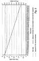
- FIG. 5The result of this measurement is presented in the diagram of Fig 5 .
- the x-axisrepresents the time, extending from close to 0 minutes to about 1500 minutes (25 hours), which is the time when the nominal volume was delivered from the pouch.
- flow and pressureare represented on the y-axis.
- Figure 5illustrates the pressure in the second chamber (dashed line) and the corresponding pressure in the accumulation tank (full line). Further, the resulting flow rate (dash dotted line) is illustrated. Accordingly, it is clearly discernible how the pressure in the accumulation tank constantly falls from a relatively high pressure level to a pressure level only slightly above the pressure in the second chamber, whereas the pressure in the second chamber, as well as the output flow rate, remain essentially constant and extremely stable during the entire process.
- the new drug administration apparatusexhibits a very stable output flow and output pressure, with a very limited variation over the entire process.
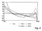
- a similar evaluationwas made for some commercially available drug administration apparatuses. The result of this evaluation is presented in the diagram of Fig 4 , in which the x-axis represents the relative amount of delivered drug, extending from 0% of the nominal value to 100% of the nominal volume. The y-axis indicates the deviation in percent at each time from the average flow.
- the evaluated administration deviceswere:
- the drug administration apparatus of the present inventionis a self-contained and portable apparatus, which, by reason of its convenience and simplicity of use, is well suited for a large variety of drug administration applications.
- the apparatus according to the inventiondoes not require any skill in use. It is easily and quickly positioned. It can easily be moved and carried by the injured person or by the medical staff, and thereby causes no hindrance in handling and transporting the patient.
- the simplicity of the constituent partsalso guarantees a low manufacturing cost. Consequently, the apparatus can also be made as a disposable, for use on only one patient. This, in combination with the separation of the pressurization system and the drug and the fact that the drug is allowed to remain in its pre-packed container, provides an extremely clean and secure drug administration, which minimizes the risk for contamination for the patient.
- the present inventionprovides, in a medical liquid administration system, means for providing an adequately regulated output pressure from the pressurization system, acting on the drug to be administered, to selectively, reliably, and accurately displace the drug and cause the drug also to flow at a substantially constant flow rate.
- the drugcan be allowed to remain in a pre-packed flexible bag during the whole administration process, and with the pressurization system fluidly separated from the drug, and is also usable with standard manufacturers' drug solution containers to provide efficient, accurate and low cost administration.
- the administration apparatus of the inventionuses a compact, reliable and cost effective pressure source (a mechanical, hand-operated pump).
- the administration apparatusis particularly reliable and cost-effective since it includes neither electronic components to control or monitor operation, nor batteries as a primary power source. Because of its compact construction the administration apparatus according to the invention is able to function even after having been dropped, and because of its lack of electronics, the pump is able to operate even if it comes into contact with water or the like from the outside. Still further, the pumping means can be made very compact, as a cup like member arranged around the accumulation tank. Still further, the present administration apparatus allows easy exchange of the pouch holding the drug.
- the second chamberproviding the external pressure on the first chamber, i.e. the pouch, within the housing
- the second chambermay be provided in various ways.
- One alternativeis to arrange the second chamber within a second pouch, or a flexible bag, as discussed above. More than one pouch forming the second chamber may lso be provided, such as two flexible bags arranged on each side of the pouch holding the drug solution.
- the administration apparatusmay be used for a large variety of different drugs, such as for use in open wounds, e.g. for post-surgical treatment, for use during surgery, for intravenous use, for epidural administration, for cancer treatment, neurosurgery, etc.
- the present administration apparatusis useable for all applications where a pressure is needed for forwarding the drug from the drug container to the place where it is needed.
- the apparatusmay be arranged to provide a predetermined output pressure and output flow from the first chamber.
- the output pressuremay be controllable, e.g. by the provision of a controllable pressure regulator between the accumulation tank and the second chamber.
- a flow regulator or controllable flow restrictorsuch as capillaries of various sizes, may be used for controlling the output flow from the first chamber.
Landscapes
- Health & Medical Sciences (AREA)
- Vascular Medicine (AREA)
- Engineering & Computer Science (AREA)
- Anesthesiology (AREA)
- Biomedical Technology (AREA)
- Heart & Thoracic Surgery (AREA)
- Hematology (AREA)
- Life Sciences & Earth Sciences (AREA)
- Animal Behavior & Ethology (AREA)
- General Health & Medical Sciences (AREA)
- Public Health (AREA)
- Veterinary Medicine (AREA)
- Physics & Mathematics (AREA)
- Fluid Mechanics (AREA)
- Infusion, Injection, And Reservoir Apparatuses (AREA)
- Feeding, Discharge, Calcimining, Fusing, And Gas-Generation Devices (AREA)
Description
- The present invention relates to a self-contained portable apparatus for administration of a drug solution, and in particular an apparatus which is usable for administration of liquid medicaments to a patient, e.g. for use in post-operative pain relief. The apparatus is arranged to provide a very uniform and controllable flow rate.
- The administration of medical liquids is largely carried out by gravity-induced hydrostatic pressure infusion of the liquid from a bottle or other container suspended above the recipient an acceptable distance. The liquid empties by gravity at a rate of flow which can be regulated by what is known as a drop-by-drop device which reduces the rate of flow by restriction or compression of the flexible tube carrying the liquid which is to be injected. Although this equipment is used in hospitals, it is however bulky, difficult to move, clumsy and slow to set up. Further, the flow rate is not easily controlled since variations in relative positions of the receiving portion of the patient and the dispensing bottle may occur with time as the patient or bottle may be shifted about.
- Moreover, previously available pressure-assisted administration devices are often quite complicated and expensive, and also often lack portability. Further, these known apparatuses are often unable to provide, as well as continuously maintain for a long time, a desired flow rate.
- Still further, most known administration devices require that the drug solution is discharged from its original container, i.e. from the prepackaged, disposable, standard medical containers, and into a administration reservoir of the administration apparatus. This is normally a rather tedious and cumbersome task, and also invokes a risk for contamination, since the solution must pass through additional handling steps in the preparation and transfer process, prior to being introduced to a patient.
- In many situations, a patient may also require a very slow and continuous introduction of medicament liquid into the patient's system, such as a few milliliters per hour for several hours, or sometimes even a day or more. It is therefore very important that these medicament liquid or pharmaceutical solution doses be administered with a highly accurate introduction rate (flow rate), which is maintained very stable during the entire process.
- To this end, many of today's administration apparatuses comprises complex electronic systems. For example, such systems may include complex valve arrangement by which the fluid is introduced into the chamber and withdrawn there from, and controlled by a electronic circuitry which includes pressure sensors and logic circuitry which controls fluid pumps which move the liquid. While relatively compact and accurate, these systems are also highly complex, expensive and requires a great deal of electrical power to operate. Further, these apparatuses are solely intended for multi-time use, which necessitates cumbersome and tedious cleaning and sterilization of the apparatuses before re-use, and also invokes a risk for contamination of the patient.
- Further, it is known from the prior art to produce portable and mechanical administration devices. For example,
US 3 640 277 discloses a self-contained portable administration apparatus using CO2 cartridges to obtain a relatively precisely regulated gas flow to displace a medical arranged in a pressure collapsible container. To this end, the pump device comprises a casing comprising a collapsible bladder holding the fluid to be driven (the medical liquid) and a second inflatable bladder to be filled with a driving fluid, whereby expansion of the second bladder causes the medical liquid to be controllably expelled. However, this device is still relatively complicated and expensive to produce, and there is also a problem of obtaining a sufficiently continuously stable and controllable pressure acting of the pressure collapsible container holding the medical liquid. Similar problems are also encountered in the apparatus disclosed inUS 5 954 696 andUS 4 673 392 , which are both related to similar types of administration apparatuses.US 3640276 ,WO 01/26715 US 5348539 andUS 4507116 show further prior art devices with pressure accumulation tanks and/or hand-operated pumps. - Consequently, there is still a need for administration apparatuses which are both capable of providing a sufficiently stable and controllable flow rate, and at the same time are safe and inexpensive to produce and use.
- It is therefore an object of the present invention to provide a self-contained, portable apparatus for administration of a drug solution, which at least alleviates the above-discussed problems of the prior art.
- This object is achieved with an administration apparatus according to the appended claims.
- There is provided a self-contained portable apparatus for administration of a drug solution, said apparatus comprising:
- a housing having an enclosure for receiving a flexible pouch containing a drug solution, wherein said enclosure has a first chamber within said pouch and a second chamber arranged outside said pouch, the chambers being arranged in a pressure-transmitting relation within said enclosure;
- an output from said first chamber connectable to a conduit for delivering said drug solution to a recipient; and
- a pressurization system for providing a constant and controllable gas pressure to said second chamber, wherein a controllable pressure is obtained in said first chamber for a controllable delivery of the drug solution.
- Further, the pressurization system comprises:
- a pressure source for delivering positive pressure gas;
- a pressure accumulation tank connected to said source and to said second chamber, arranged to provide a positive pressure reservoir;
- a one-way valve arranged between said pressure source and said pressure accumulation tank, enabling gas to flow solely in the direction from the pressure source to the pressure accumulation tank; and
- a mechanical pressure regulator arranged between said pressure accumulation tank and said second chamber.
- The administration apparatus according to the invention is relatively simple, and can be produced relatively cost-effectively. Hereby, it is possible to provide this administration apparatus as a disposable, for one-time use, and the like, which makes it very safe and secure from a contamination point of view. Further, the inventive pressurization system, involving inter alia an accumulation tank, enables the provision of a very stable and controllable system, where the pressure acting on the flexible pouch containing the drug solution in the enclosure of the housing is extremely stable over time, and essentially constant even when the flexible pouch is full or nearly empty. Accordingly, the present invention provides a very stable and constant outgoing pressure for the drug solution. Further, the pressure in the pressurization system may always be kept below 3 bar, which reduces the safety risks of the system, and also reduces the safety requirements of the system. The only exception to this is, possibly, the pressure source, where higher pressures may provided. However, in that case the accumulation tank functions as a buffer to the rest of the system, thereby ensuring adequate safety of the overall system.
- The present administration apparatus may be equipped with any type of flexible pouch for holding the drug solution, such as prepackaged, disposable, standard medical containers of flexible materials.
- The invention is particularly useful for administration of e.g. pain relieving agents such as anesthetics during post-operation treatment of a patient at a low administration rate during a prolonged time. For example, the apparatus may be arranged to provide an output flow rate of the drug solution in the range 1 - 200 ml/h, and preferably in the range 1 - 20 ml/h, and most preferably in the range 4-12 ml/h. Further, the apparatus may be arranged to provide an essentially constant output pressure and output flow rate for at least 1 hour, and preferably for at least 12 hours, and most preferably for at least 24 hours.
- The administration apparatus may be used for any type of drug solution, such as liquid medicaments for post-surgery pain relief, such as solutions of ropivakain and other local anesthetics, for instance Narop® and Naropin®, both produced by AstraZeneca. However, the administration apparatus may also be used to deliver intravenous fluids and solutions for a wide variety of medical therapies including chemotherapy, antiviral and antibiotic therapy, and also include intravenous introduction of saline solutions, glucose solutions and various other solutions comprising pharmaceuticals. In e.g. post-surgery use of anesthesia, the drug solution may be administered through a catheter after surgery and after closing of the surgical incision.
- The present invention is an entirely mechanical construction, which does not need any electronics or the like for its operation. Further, the apparatus may be made very compact, and thereby portable and self-contained. Still further, the drug solution is at all times maintained separated from the pressurization system, which makes the apparatus very safe, and significantly reduces the risk for contamination of the drug solution, and also makes it possible to use less expensive materials in the pressurization system, since these materials need not be compatible for the drug solution, etc.
- Due to the extremely accurate pressure provided by the pressurization system and acting on the flexible pouch holding the drug solution, no flow regulation or the like are in principle needed in the conduit transferring the drug solution to the patient. However, in most cases flow control means may still be advantageous in the conduit system. For example, it may be advantageous to provide a branched conduit system, with one branch providing a continuous drug administration to the patient, and a second branch with a liquid reservoir providing the possibility of bolus doses. Typically, the continuous drug administration can e.g. be 1-20 ml/h, and preferably 2-14 ml/h, and the batch-wise (bolus) dosages can be e.g. 5-30 ml extra every 1-6 hour. Further, since the pressurization system provides an essentially constant pressure on the flexible pouch holding the drug solution, it also becomes possible to control the output liquid flow from the apparatus with great accuracy, and by relatively simple means.
- The pressure source according to the invention is a hand-operated pump. Hereby, the pump may be used to manually fill the accumulation tank with an adequate pressure before starting the drug administration, and may also be used during use, for increasing the pressure in the accumulation tank. According to the invention, the pump comprises an air compression cup which is slideably arranged over the pressure accumulation tank. Hereby, a very compact product is obtainable.
- The one-way valve ensures that pressurized gas is only transferred in the direction from the pressure source to the accumulation tank, and not in the reverse direction. This makes it possible only to activate the pressure source temporarily or intermittently, such as only initially, before starting the drug administration to the patient, or only when the pressure in the accumulation tank becomes lower than a predetermined threshold value.
- The mechanical pressure regulator guarantees that a stable and constant gas pressure is provided from the accumulation tank to the second chamber, and that the pressure in the enclosure is automatically adjusted during the emptying of the flexible pouch holding the drug solution. Such mechanical pressure regulators are per se previously known.
- The apparatus is preferably arranged to provide an essentially constant output pressure for the drug solution, said output pressure preferably being in the range 0.1 - 1.0 bar, and most preferably 0.3 - 0.6 bar.
- The pressure accumulation tank is preferably capable of accumulating a pressure exceeding 1 bar, and preferably exceeding 2 bar. Further, as a safety measure, the pressure accumulation tank is preferably provided with a high-pressure relief valve, arranged to release pressure from the accumulation tank if the pressure exceeds a certain threshold limit, such as a threshold limit of 3 bar. Similarly, the enclosure in the housing may be provided with a high-pressure relief valve, arranged to release pressure from enclosure if the pressure exceeds a certain threshold limit.
- In three examples not according to the invention, the second chamber is arranged as an expandable bladder, said bladder being arranged adjacent to said flexible pouch within said enclosure, or the second chamber may be provided in the enclosure by means of a flexible membrane arranged between a compartment holding the first chamber and a compartment forming the second chamber, or the second chamber may be the entirety of the enclosure being exteriorly from the flexible pouch holding the drug solution, whereby the gas acts directly on the flexible pouch.
- The housing is made of relatively rigid material, and preferably a rigid plastic material.
- A manometer is preferably arranged on the pressure accumulation tank, for providing an indication of the current pressure in said tank. This can be used for monitoring the present pressure of the tank, and also for monitoring the operation of the drug administration.
- Further, the housing is preferably further provided with a manually controllable valve for releasing the pressure of the second chamber. Hereby, the pressure of the second chamber can at all times be released to atmosphere pressure, for e.g. for exchange of the flexible pouch or other maintenance operations.
- Still further, the mechanical pressure regulator arranged between said pressure accumulation tank and said second chamber is preferably controllable to provide different pressures to the second chamber. Hereby, the pressure in the second chamber becomes controllable, and can be set for different pressure levels by means of controlling the pressure regulator. This may e.g. be used for set-up of the administration apparatus for various types of use, or for controlling the pressure of the second chamber during use, for controlling the output flow of the drug solution.
- There is also disclosed a method for administration of a drug solution, comprising the steps:
- providing a flexible pouch containing a drug solution in a housing; and
- providing a pressure in a second chamber arranged outside said pouch within said housing, said pressure thereby acting on the flexible pouch for delivering said drug solution to a recipient;
- providing a positive pressure from a pressure source;
- forwarding at least part of said pressure from the pressure source to a pressure accumulation tank connected to said source through in a non-returnable way; and
- forwarding at least part of said pressure from the pressure accumulation tank to the second chamber through a mechanical pressure regulator arranged between said pressure accumulation tank and said second chamber.
- For exemplifying purposes, the invention will be described in closer detail in the following with reference to embodiments thereof illustrated in the attached drawings, wherein:
Fig 1 is a schematic view of the principal construction of an administration apparatus ;Fig 2 shows an embodiment of an administration apparatus according to the present invention;Fig 3 is an exploded view of the administration apparatus offig 2 ;Fig 4 is a diagram illustrating the deviation in the average output flow over the entire operation cycle for the present invention and a number of comparative examples; andFig 5 is a diagram illustrating the measured pressure in the second chamber and the accumulation tank, as well as the resulting flow for the second chamber, of the administration apparatus offig 2 and3 during operation.- The invention will now be discussed in more detail by means of embodiments. Unless otherwise is specifically mentioned, the same reference numerals are used to denominate similar or corresponding parts throughout the drawings and the specification.
- An administration apparatus for administration of a drug solution according to an example not according to the invention, as illustrated in
fig 1 , comprises ahousing 1 having anenclosure 2 for receiving a flexible pouch (not shown) containing a drug solution. In this context "flexible" indicates that the pouch forms a pressure-collapsible container, whereby the liquid arranged in the pouch is releasable by compression operating thereon. The enclosure forms a first chamber within said pouch and a second chamber arranged outside said pouch, wherein the chambers are arranged in a pressure-transmitting relation within said enclosure. Hereby, the pressure provided in the second chamber is transferred to the first chamber, and consequently the pressure provided in the second chamber is essentially equal to the pressure obtained in the drug solution contained in the flexible pouch. - Thus, the housing forms separate chambers for the driving gas and the driven drug solution, formed by separate and abutting collapsible containers, respectively, having a large common interface. The housing forms a rigid container or frame. Part of the housing is formed by a lid or removable wall section, to permit insertion of a new medical container of drug solution, and removal of an emptied container.
- The housing is preferably made at least partly of a transparent plastic material in order to permit immediate visual monitoring of the condition of the inner bag. Further, the housing may be injection molded, pressure formed, or the like.
- An output from the first chamber is connectable to a conduit (not shown) for delivering said drug solution to a recipient, and in particular to a patient. For example, the conduit may comprise tubing leading from the first chamber, a valve for opening and closing the conduit and a catheter for introduction of the drug solution into the patient. For example, it may be advantageous to provide a branched conduit system, with one branch providing a continuous drug administration to the patient, and a second branch with a reservoir of drug solution providing the possibility of bolus doses. Such conduits are per se known in the art, and will not be discussed in any detail in this application.
- Further, the administration apparatus comprises a pressurization system for providing a constant and controllable gas pressure to said second chamber. The pressurization system comprises a
pressure source 3 for delivering positive pressure gas. In this example and in the invention, the pressure source is a hand-actuated pump, but other pressure sources, such as a liquid gas cartridge, are also feasible. A pressurized driving fluid supply meeting these requirements is e.g. a cartridge in which is stored liquefied CO2, fluorocarbons or hydrocarbons contained under pressures required to maintain liquid-gas equilibrium, or gases such as N2 or air under high pressure. Another alternative example not according to the invention would be to use an external pressure source, which could then be used for loading the accumulation tank before use of the apparatus, and possible even for subsequent reloading during use. - The
pressure source 3 is connected to apressure accumulation tank 5, which provides a positive pressure reservoir. The accumulation tank is preferably arranged to be pressurized up to a positive pressure during initialization of the administration apparatus, e.g. up to 1-2 bar, or even up to 3 bar. However, it is in many cases an advantage to have an accumulation tank having a pressure below 3 bar connected to the administration system, since this provides lower safety risks, and therefore requires less safety requirements. In many applications, the initial loading of the accumulation tank will be sufficient for the whole administration process. However, it is also possible to reload the accumulation tank during operation. Between thepressure source 3 and the accumulation tank 5 a one-way valve 4 is provided, which allows gas to flow from the pressure source to the accumulation tank, but prevents gas from flowing in the opposite direction. - The accumulation tank is connected to the second chamber within the
enclosure 2 via amechanical pressure regulator 6, arranged to control the pressure within the second chamber to a predetermined pressure level, said pressure level being lower than the pressure of the accumulation tank. The pressure regulator is arranged to mechanically and automatically control the output pressure to a predetermined value. Optionally, this predetermined value may be manually controllable, in order to enable adjustment of the predetermined value during operation, or for adjustment between various types of operations. Thus, thepressure regulator 6 reduces the pressure of the driving fluid from a lever p1 to a level p2, and the latter may be varied within limits by adjustment of a regulator control (not shown). Normally, p2 is much less than p1. The regulator control for adjustment of the output pressure may e.g. adjust a spring tension in the regulator. Several pressure regulators, both of spring and diaphragm type, are per se known in the art, and are commercially available. - The administration apparatus according to the invention is arranged as a self-contained and portable device. Even though this goal may be achieved by means of the apparatus discussed above in respect of
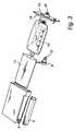
Figure 1 ,Figures 2 and3 illustrate an even more compact, portable and self-contained apparatus, which represents an embodiment of the invention. - The
housing 1 receives aflexible pouch 10 for holding the drug solution, such as prepackaged, disposable, standard medical containers of flexible materials, said pouch forming the first chamber. In practice, any one of a number of standard drug solution containers may be used with the administration apparatus of the present invention, but solution containers in the range 50-500 ml are preferred, and most preferably in the rage 100-300 ml. - An
inflatable bladder 11 is wrapped around theflexible pouch 10 and also arranged within thehousing 1, thereby forming the second chamber. - The
housing 1 forms a receptacle with anopenable lid 13. After insertion of theflexible pouch 10, thelid 13 is closed. Preferably, the lid is arranged with a snap lock, such as flexible locking arms 15. However, the lid may be attached to the housing bottom by any of a variety of conventional mechanical fasteners, such as push-pins, screws, snap-fit posts and detents, and the like. - Further, the lid is preferably arranged with an
inner wall 14 to be inserted into thehousing 1. Hereby, the lid stabilizes the housing, and thereby aids in the resistance against the positive pressure building up within the housing during operation. Still further, the lid is preferably arranged with anoutput opening 16, which is connectable to a conduit (not shown) for delivering said drug solution to a recipient, and in particular to a patient. The conduit for delivering the drug solution to the patient may comprise a needle or other device, such as a catheter, for administering fluids, and tubing connecting theoutput opening 16 to the needle or catheter end. The conduit may also comprise filters, such as air elimination filters and particle elimination filters, bisections for enabling both bolus doses and continuous administration, flow controlling resistive lumen or orifices etc. Such conduits are per se known in the art. - The output opening may be connected to an internal needle or spike, which penetrates a membrane of the flexible pouch during insertion of the pouch into the housing and closing of the lid. Hereby, fluid connection between the flexible pouch and the administration conduit is obtained automatically during arrangement of the flexible pouch within the housing. The drug spike may be of the type which is per se well known in the art. However, other type of access means are feasible. For example, the output opening may simply be an opening, through which a connection part of the flexible pouch is accessible.
- The pressurization system is arranged on the side of the housing, and formed as integrated parts on or within the
housing 1. In this embodiment, theaccumulation tank 5 is arranged at the side of the housing, and essentially extending over the whole length of the housing. A gap is formed between the accumulation tank and the housing in one end of the tank, so that the accumulation tank is only connected to the housing in one end. Further, the accumulation tank has a uniform cross-section at least in the part not connected to the housing, and preferably an essentially circular cross-section. Further, an opening with anon-return valve 4 is arranged at the end side of the non-connected end of the tank. A hand-actuated pump, functioning as apressure source 3, is arranged outside theaccumulation tank 5, and in particular outside the part of the tank which is not connected to the housing, and is displaceable or slideable in the length direction of the tank. Hereby, the pump forms a cylinder, or a compression cup, with an internal cross-section which generally corresponds to the external cross-section of the corresponding part of the accumulation tank, whereby a relatively tight seal is formed between the pump and the accumulation tank. In other examples not according to the invention, other alternative pressure sources may also be used for filling the accumulation tank, such as a liquefied gas container, and preferably a liquefied CO2 container or a container of pressurized air. - The
accumulation tank 5 is connected to theinflatable bladder 11 within theenclosure 2 via amechanical pressure regulator 6, arranged to control the pressure within the inflatable bladder to a predetermined pressure level, lower than the pressure of the accumulation tank. - During operation, the
pump 3 is displaced up and down on the accumulation tank, whereby air is forced through the one-way valve 4 into theaccumulation tank 5, whereby a pressure is built up in the tank. This positive pressure is gradually released to theinflatable bladder 11 through the exact control of theregulator 6, whereby a very exact and constant pressure is applied on the liquid medicine arranged in theflexible pouch 10. - The volume of the pressure accumulation tank as well as the initial pressure as provided by the pressure source are preferably selected in dependence of the total volume of the drug to be administered, and the desired output pressure in the second chamber of the housing. Preferably, the volume of the accumulation tank is relatively small, in order to reduce the overall size of the apparatus. For example, it is preferred that the accumulation tank has an internal volume Vacc that is less than the internal volume Vpouch of the pouch (first chamber) holding the drug solution, and preferably less than 70% of this volume, and most preferably less than 50% of this volume. Further, it is preferred that the pressure source is operable to provide an initial pressure to the accumulation tank that is sufficient to completely empty the pouch. Accordingly, the pressure source is preferably operable to provide a pressure Pacc,initial to the accumulation tank that fulfills the following condition:

where Preg is the regulated pressure of the second chamber, acting on the first chamber (i.e. the pouch), Vpouch is the volume of the pouch, i.e. the volume of the drug to be administered, and Vacc is the volume of the accumulation tank. - The administration apparatus is particularly useful for administration of e.g. pain relieving agents such as anesthetics during post-operation treatment of a patient at a low administration rate during a prolonged time. For example, the apparatus may be arranged to provide an output flow rate of the drug solution in the range 1 - 200 ml/h, and preferably in the range 1 - 20 ml/h, and most preferably in the range 4-12 ml/h. Further, the apparatus may be arranged to provide an essentially constant output pressure and output flow rate for at least 1 hour, and preferably for at least 12 hours, and most preferably for at least 24 hours. Further, an essentially constant output pressure for the drug solution can hereby be provided, e.g. in the range 0.1 - 1.0 bar, and most preferably 0.3 - 0.6 bar.
- Further, as a safety measure, the pressure accumulation tank is preferably provided with a high-
pressure relief valve 12, arranged to release pressure from the accumulation tank if the pressure exceeds a certain threshold limit. Similarly, the enclosure in the housing may be provided with a high-pressure relief valve, arranged to release pressure from enclosure if the pressure exceeds a certain threshold limit. The high-pressure relief valve may also be arranged to provide an alarm sound or the like, such as a whistle tone, when it is activated. Manometers and the like may also be provided to indicate the present pressure in e.g. the accumulation tank or the second chamber during use. Such a manometer may also be used for monitoring the flow of drug solution out of the administration apparatus, and/or as a measure of the amount of drug solution remaining in the flexible pouch. - An administration apparatus as discussed above with reference to
Fig 2 was used for experimental measurements. The output of the apparatus was connected to a flow regulator, which allowed a flow of 4 ml/h at an overpressure of 0.4 bar. The output of the flow regulator was forwarded through a catheter, and the drug administered through the catheter was collected and weighed. Further, manometers were used to measure the pressure in the first and second chamber of the housing. - For the experiments, a pouch holding a drug solution was arranged in the housing, and administered by means of the administration apparatus. The weight of the administered drug was continuously measured, together with the pressure in the first and second chamber, until the nominal volume was delivered from the pouch.
- The result of this measurement is presented in the diagram of
Fig 5 . In this diagram, the x-axis represents the time, extending from close to 0 minutes to about 1500 minutes (25 hours), which is the time when the nominal volume was delivered from the pouch. On the y-axis, flow and pressure are represented.Figure 5 illustrates the pressure in the second chamber (dashed line) and the corresponding pressure in the accumulation tank (full line). Further, the resulting flow rate (dash dotted line) is illustrated. Accordingly, it is clearly discernible how the pressure in the accumulation tank constantly falls from a relatively high pressure level to a pressure level only slightly above the pressure in the second chamber, whereas the pressure in the second chamber, as well as the output flow rate, remain essentially constant and extremely stable during the entire process. - Accordingly, the new drug administration apparatus exhibits a very stable output flow and output pressure, with a very limited variation over the entire process. As a comparison, a similar evaluation was made for some commercially available drug administration apparatuses. The result of this evaluation is presented in the diagram of
Fig 4 , in which the x-axis represents the relative amount of delivered drug, extending from 0% of the nominal value to 100% of the nominal volume. The y-axis indicates the deviation in percent at each time from the average flow. The evaluated administration devices were: - the administration apparatus according to the present invention. (Dotted line);
- comparative example I is an elastomeric balloon infusion system with a nominal flow rate of 5 ml/h and a nominal volume of 240 ml. (Dashed line);
- comparative example II is an elastomeric balloon infusion system with a nominal flow rate of 5 ml/h and a nominal volume of 270 ml. (Full line);
- comparative example III is a spring-operated infusion system with a nominal flow rate of 4 ml/h and a maximum volume of 100 ml. (Dash dotted line); and
- comparative example IV is an elastomeric balloon infusion system with a nominal flow rate of 5 ml/h and a nominal volume of 275 ml. (Dash dotted line with double dots).
- From the evaluation in
Fig 4 , it is clearly noticeable that the commercially available comparative examples I - IV all have much higher deviations from the average flow rate during the process, and typically with a flow rate much above the average in the initial phase, when the chamber or pouch containing the drug solution is full, and with a flow rate much below average during the final phase, when the chamber/pouch is almost empty. - The drug administration apparatus of the present invention is a self-contained and portable apparatus, which, by reason of its convenience and simplicity of use, is well suited for a large variety of drug administration applications. The apparatus according to the invention does not require any skill in use. It is easily and quickly positioned. It can easily be moved and carried by the injured person or by the medical staff, and thereby causes no hindrance in handling and transporting the patient. The simplicity of the constituent parts also guarantees a low manufacturing cost. Consequently, the apparatus can also be made as a disposable, for use on only one patient. This, in combination with the separation of the pressurization system and the drug and the fact that the drug is allowed to remain in its pre-packed container, provides an extremely clean and secure drug administration, which minimizes the risk for contamination for the patient.
- At the same time, the present invention provides, in a medical liquid administration system, means for providing an adequately regulated output pressure from the pressurization system, acting on the drug to be administered, to selectively, reliably, and accurately displace the drug and cause the drug also to flow at a substantially constant flow rate. Hereby, the drug can be allowed to remain in a pre-packed flexible bag during the whole administration process, and with the pressurization system fluidly separated from the drug, and is also usable with standard manufacturers' drug solution containers to provide efficient, accurate and low cost administration.
- The administration apparatus of the invention uses a compact, reliable and cost effective pressure source (a mechanical, hand-operated pump). The administration apparatus is particularly reliable and cost-effective since it includes neither electronic components to control or monitor operation, nor batteries as a primary power source. Because of its compact construction the administration apparatus according to the invention is able to function even after having been dropped, and because of its lack of electronics, the pump is able to operate even if it comes into contact with water or the like from the outside. Still further, the pumping means can be made very compact, as a cup like member arranged around the accumulation tank. Still further, the present administration apparatus allows easy exchange of the pouch holding the drug.
- A specific embodiment of the invention has now been described. However, in other examples not according to the invention, several alternatives are possible, as would be apparent for someone skilled in the art. For example, the second chamber, providing the external pressure on the first chamber, i.e. the pouch, within the housing may be provided in various ways. One alternative is to arrange the second chamber within a second pouch, or a flexible bag, as discussed above. More than one pouch forming the second chamber may lso be provided, such as two flexible bags arranged on each side of the pouch holding the drug solution. Another alternative to make the housing air-tight, whereby the second chamber may be the part of the housing externally from the pouch holding the drug solution.
- Further, even though an important application of the present administration apparatus is to administer a drug solution, such as anesthetics, directly to a patient, other applications are also feasible, such as administration of a drug solution to another apparatus or the like. Further, the administration apparatus may be used for a large variety of different drugs, such as for use in open wounds, e.g. for post-surgical treatment, for use during surgery, for intravenous use, for epidural administration, for cancer treatment, neurosurgery, etc. In general, the present administration apparatus is useable for all applications where a pressure is needed for forwarding the drug from the drug container to the place where it is needed.
- Still further, the apparatus may be arranged to provide a predetermined output pressure and output flow from the first chamber. Alternatively, the output pressure may be controllable, e.g. by the provision of a controllable pressure regulator between the accumulation tank and the second chamber. Alternatively or additionally, a flow regulator or controllable flow restrictor, such as capillaries of various sizes, may be used for controlling the output flow from the first chamber.

Claims (15)
- A self-contained portable apparatus for administration of a drug solution, said apparatus comprising:a housing having an enclosure (2) for receiving a flexible pouch (10) containing a drug solution, wherein said enclosure has a first chamber within said pouch and a second chamber arranged outside said pouch, the chambers being arranged in a pressure-transmitting relation within said enclosure, wherein the housing is made of relatively rigid material;an output from said first chamber connectable to a conduit for delivering said drug solution to a recipient; anda pressurization system for providing a constant and controllable gas pressure to said second chamber, wherein a controllable pressure is obtained in said first chamber for a controllable delivery of the drug solution, wherein said pressurization system comprises:characterized in that the pressurization system is integrated on or within the housing, wherein the accumulation tank (5) is arranged on a side of the housing,in that the pressure source comprises a mechanical, hand-operated pump, wherein the pump comprises an air compression cup which is slideably arranged over the pressure accumulation tank, andin that the second chamber forms an inflatable bladder (11) which is wrapped around the flexible pouch containing the drug solution.a pressure source (3) for delivering positive pressure gas;a pressure accumulation tank (5) connected to said source and to said second chamber, arranged to provide a positive pressure reservoir;a one-way valve (4) arranged between said pressure source and said pressure accumulation tank, enabling gas to flow solely in the direction from the pressure source to the pressure accumulation tank; anda mechanical pressure regulator (6) arranged between said pressure accumulation tank and said second chamber,
- The apparatus of claim 1, wherein the drug solution is an anesthetic.
- The apparatus of any one of the preceding claims, wherein it is arranged to provide an output flow rate of the drug solution in the range 1 - 200 ml/h, and preferably in the range 1 - 20 ml/h, and most preferably in the range 4-12 ml/h.
- The apparatus of any one of the preceding claims, wherein it is arranged to provide an essentially constant output flow rate for at least 1 hour, and preferably for at least 12 hours, and most preferably for at least 24 hours.
- The apparatus of any one of the preceding claims, wherein it is arranged to provide an essentially constant output pressure for the drug solution, said output pressure preferably being in the range 0.1 - 1.0 bar, and most preferably 0.3 - 0.6 bar
- The apparatus of any one of the preceding claims, wherein the pressure accumulation tank is capable of accumulating a pressure exceeding 1 bar, and preferably exceeding 2 bar.
- The apparatus of any one of the preceding claims, wherein the pressure accumulation tank is provided with a high-pressure relief valve, arranged to release pressure from the accumulation tank if the pressure exceeds a certain threshold limit.
- The apparatus of claim 7, wherein the high-pressure relief valve is arranged to maintain a pressure below about 3 bar in the accumulation tank.
- The apparatus of any one of the preceding claims, wherein the enclosure in the housing is provided with a high-pressure relief valve, arranged to release pressure from enclosure if the pressure exceeds a certain threshold limit.
- The apparatus of any one of the preceding claims, wherein the housing is made of a rigid plastic material.
- The apparatus of any one of the preceding claims, wherein the apparatus forms a disposable product for one time use.
- The apparatus of any one of the preceding claims, wherein the enclosure of the housing is arranged to receive a pouch of drug solution which is a standard disposable pre-filled medicament container.
- The apparatus of any one of the preceding claims, wherein a manometer is arranged on the pressure accumulation tank, for providing an indication of the current pressure in said tank.
- The apparatus of any one of the preceding claims, wherein the housing is further provided with a manually controllable valve for releasing the pressure of the second chamber.
- The apparatus of any one of the preceding claims, wherein the mechanical pressure regulator arranged between said pressure accumulation tank and said second chamber is controllable to provide different pressures to the second chamber.
Priority Applications (8)
| Application Number | Priority Date | Filing Date | Title |
|---|---|---|---|
| EP11187040AEP2446911A3 (en) | 2007-10-12 | 2007-10-12 | Self-contained portable apparatus for administration of a drug solution |
| EP07118365AEP2047876B1 (en) | 2007-10-12 | 2007-10-12 | Self-contained portable apparatus for administration of a drug solution |
| JP2010528395AJP5662800B2 (en) | 2007-10-12 | 2008-10-09 | Self-contained portable device for drug administration |
| CN2008801109875ACN101820935B (en) | 2007-10-12 | 2008-10-09 | Self-contained portable apparatus for administration of drug solution |
| PCT/EP2008/063531WO2009047289A1 (en) | 2007-10-12 | 2008-10-09 | Self-contained portable apparatus for administration of a drug solution |
| AU2008309614AAU2008309614B2 (en) | 2007-10-12 | 2008-10-09 | Self-contained portable apparatus for administration of a drug solution |
| US12/285,700US8267894B2 (en) | 2007-10-12 | 2008-10-10 | Self-contained portable apparatus for administration of a drug solution |
| US13/598,476US20120330272A1 (en) | 2007-10-12 | 2012-08-29 | Self-contained portable apparatus for administration of a drug solution |
Applications Claiming Priority (1)
| Application Number | Priority Date | Filing Date | Title |
|---|---|---|---|
| EP07118365AEP2047876B1 (en) | 2007-10-12 | 2007-10-12 | Self-contained portable apparatus for administration of a drug solution |
Related Child Applications (1)
| Application Number | Title | Priority Date | Filing Date |
|---|---|---|---|
| EP11187040ADivision-IntoEP2446911A3 (en) | 2007-10-12 | 2007-10-12 | Self-contained portable apparatus for administration of a drug solution |
Publications (2)
| Publication Number | Publication Date |
|---|---|
| EP2047876A1 EP2047876A1 (en) | 2009-04-15 |
| EP2047876B1true EP2047876B1 (en) | 2012-08-29 |
Family
ID=38846870
Family Applications (2)
| Application Number | Title | Priority Date | Filing Date |
|---|---|---|---|
| EP07118365ANot-in-forceEP2047876B1 (en) | 2007-10-12 | 2007-10-12 | Self-contained portable apparatus for administration of a drug solution |
| EP11187040AWithdrawnEP2446911A3 (en) | 2007-10-12 | 2007-10-12 | Self-contained portable apparatus for administration of a drug solution |
Family Applications After (1)
| Application Number | Title | Priority Date | Filing Date |
|---|---|---|---|
| EP11187040AWithdrawnEP2446911A3 (en) | 2007-10-12 | 2007-10-12 | Self-contained portable apparatus for administration of a drug solution |
Country Status (5)
| Country | Link |
|---|---|
| US (2) | US8267894B2 (en) |
| EP (2) | EP2047876B1 (en) |
| JP (1) | JP5662800B2 (en) |
| CN (1) | CN101820935B (en) |
| WO (1) | WO2009047289A1 (en) |
Families Citing this family (26)
| Publication number | Priority date | Publication date | Assignee | Title |
|---|---|---|---|---|
| US10208158B2 (en) | 2006-07-10 | 2019-02-19 | Medipacs, Inc. | Super elastic epoxy hydrogel |
| JP2011505520A (en) | 2007-12-03 | 2011-02-24 | メディパックス インコーポレイテッド | Fluid metering device |
| WO2011032011A1 (en) | 2009-09-10 | 2011-03-17 | Medipacs, Inc. | Low profile actuator and improved method of caregiver controlled administration of therapeutics |
| US20110172639A1 (en)* | 2010-01-08 | 2011-07-14 | Ratio, Inc. | Device and method for delivery of microneedle to desired depth within the skin |
| US20110172645A1 (en)* | 2010-01-08 | 2011-07-14 | Ratio, Inc. | Wearable drug delivery device including integrated pumping and activation elements |
| US20110172609A1 (en)* | 2010-01-08 | 2011-07-14 | Ratio, Inc. | Microneedle component assembly for drug delivery device |
| US20110172637A1 (en)* | 2010-01-08 | 2011-07-14 | Ratio, Inc. | Drug delivery device including tissue support structure |
| US9500186B2 (en) | 2010-02-01 | 2016-11-22 | Medipacs, Inc. | High surface area polymer actuator with gas mitigating components |
| WO2012061556A1 (en) | 2010-11-03 | 2012-05-10 | Flugen, Inc. | Wearable drug delivery device having spring drive and sliding actuation mechanism |
| FR2976356B1 (en)* | 2011-06-11 | 2013-11-08 | Pascal Lucchina | PRESSURE INDICATOR. |
| CN103874519B (en)* | 2011-06-24 | 2016-03-16 | 解救点滴有限公司 | Elasticity infusion pump |
| EP2965768B1 (en)* | 2012-01-10 | 2017-11-29 | KCI Licensing, Inc. | Systems for delivering fluid to a wound therapy dressing |
| EP2628494A1 (en)* | 2012-02-17 | 2013-08-21 | Sensile Pat AG | Liquid storage and delivery system |
| US10000605B2 (en) | 2012-03-14 | 2018-06-19 | Medipacs, Inc. | Smart polymer materials with excess reactive molecules |
| US9226792B2 (en)* | 2012-06-12 | 2016-01-05 | Medtronic Advanced Energy Llc | Debridement device and method |
| CN103100125B (en)* | 2013-02-21 | 2014-08-27 | 深圳市万聚源科技有限公司 | Air non-return pressure relief device |
| US9867931B2 (en) | 2013-10-02 | 2018-01-16 | Cook Medical Technologies Llc | Therapeutic agents for delivery using a catheter and pressure source |
| EP3212253B1 (en)* | 2014-10-28 | 2019-03-13 | Ferrosan Medical Devices A/S | Time controlled periodic infusion |
| US10376302B2 (en) | 2015-02-18 | 2019-08-13 | Medtronic Xomed, Inc. | Rotating electrical connector for RF energy enabled tissue debridement device |
| AU2016219980B2 (en) | 2015-02-18 | 2020-09-03 | Medtronic Xomed, Inc. | RF energy enabled tissue debridement device |
| US10188456B2 (en) | 2015-02-18 | 2019-01-29 | Medtronic Xomed, Inc. | Electrode assembly for RF energy enabled tissue debridement device |
| EP3573686A1 (en)* | 2017-01-24 | 2019-12-04 | Sanofi-Aventis Deutschland GmbH | Medicament delivery device |
| IT201800010220A1 (en)* | 2018-11-09 | 2020-05-09 | Pfm Medical Ag | MOBILE HYDRATION SYSTEM TO INJECT A LIQUID BY INFUSION, IN PARTICULAR A SALINE SOLUTION OR A RINGER SOLUTION, INTO THE HUMAN OR ANIMAL BODY |
| EP4161346A2 (en) | 2020-06-05 | 2023-04-12 | Cook Medical Technologies LLC | Medical scopes for delivering therapeutic agents |
| US12268840B2 (en) | 2021-01-22 | 2025-04-08 | Proportion-Air, Inc | System for dispensing fluid |
| CN115957393B (en)* | 2022-12-07 | 2023-12-15 | 香港大学深圳医院 | Chemotherapy pump |
Family Cites Families (19)
| Publication number | Priority date | Publication date | Assignee | Title |
|---|---|---|---|---|
| US3153414A (en)* | 1962-02-02 | 1964-10-20 | Abbott Lab | Apparatus for the induced infusion of liquid from a flexible liquid container |
| US3468308A (en)* | 1966-01-17 | 1969-09-23 | Howard R Bierman | Pressure infusion device for ambulatory patients with pressure control means |
| US3640276A (en)* | 1970-01-09 | 1972-02-08 | Allis Chalmers Mfg Co | Apparatus for making intravenous or intra-arterial injections |
| US4090514A (en)* | 1976-10-22 | 1978-05-23 | Howard Helmut Hinck | Pressure infusion device |
| US4507116A (en)* | 1982-04-22 | 1985-03-26 | Saul Leibinsohn | Apparatus for the induced infusion of a liquid from a flexible liquid bag |
| IL65580A0 (en)* | 1982-04-22 | 1982-07-30 | Leibinsohn Saul | Apparatus for the induced infusion of a liquid |
| US4551136A (en)* | 1983-04-11 | 1985-11-05 | Medex, Inc. | Pressure infusor |
| CA1272918A (en)* | 1986-04-15 | 1990-08-21 | Paul Y. Wang | Compression device enabling flexible solution containers to produce constant delivery rate |
| US4968301A (en)* | 1989-02-02 | 1990-11-06 | Imed Corporation | Disposable infusion device |
| US5163909A (en)* | 1991-01-28 | 1992-11-17 | Alan E. Jordan | Medical fluid delivery system |
| US5348539A (en)* | 1993-06-29 | 1994-09-20 | Glenn Herskowitz | Infusion pump for use with prepackaged IV bags |
| US5810202A (en)* | 1994-10-20 | 1998-09-22 | Rick R. Wascher, P.C. | Disposable self-dispensing pressurized package for delivery of sterile fluids and solutions |
| US5554123A (en)* | 1994-10-31 | 1996-09-10 | Glenn Herskowitz | Portable infusion pump |
| US5681284A (en)* | 1994-10-31 | 1997-10-28 | Glenn Herskowitz | Infusion pump with tube spike holder |
| US5891096A (en)* | 1996-08-20 | 1999-04-06 | Critical Device Corporation | Medicament infusion device |
| JPH10113385A (en)* | 1996-10-15 | 1998-05-06 | Nissho Corp | Liquid medicine continuous injection device |
| US5954696A (en)* | 1997-12-15 | 1999-09-21 | B. Braun Medical, Inc. | Pressure infusion pump |
| US6382923B1 (en)* | 1999-07-20 | 2002-05-07 | Deka Products Ltd. Partnership | Pump chamber having at least one spacer for inhibiting the pumping of a gas |
| SE9903683D0 (en)* | 1999-10-13 | 1999-10-13 | Goeran Ewerloef | Infusion device for use with an infusion bag |
- 2007
- 2007-10-12EPEP07118365Apatent/EP2047876B1/ennot_activeNot-in-force
- 2007-10-12EPEP11187040Apatent/EP2446911A3/ennot_activeWithdrawn
- 2008
- 2008-10-09JPJP2010528395Apatent/JP5662800B2/ennot_activeExpired - Fee Related
- 2008-10-09CNCN2008801109875Apatent/CN101820935B/ennot_activeExpired - Fee Related
- 2008-10-09WOPCT/EP2008/063531patent/WO2009047289A1/enactiveApplication Filing
- 2008-10-10USUS12/285,700patent/US8267894B2/ennot_activeExpired - Fee Related
- 2012
- 2012-08-29USUS13/598,476patent/US20120330272A1/ennot_activeAbandoned
Also Published As
| Publication number | Publication date |
|---|---|
| AU2008309614A1 (en) | 2009-04-16 |
| JP5662800B2 (en) | 2015-02-04 |
| CN101820935A (en) | 2010-09-01 |
| WO2009047289A1 (en) | 2009-04-16 |
| EP2047876A1 (en) | 2009-04-15 |
| US20120330272A1 (en) | 2012-12-27 |
| CN101820935B (en) | 2013-12-04 |
| JP2011500117A (en) | 2011-01-06 |
| EP2446911A3 (en) | 2012-05-09 |
| US8267894B2 (en) | 2012-09-18 |
| EP2446911A2 (en) | 2012-05-02 |
| US20090099545A1 (en) | 2009-04-16 |
Similar Documents
| Publication | Publication Date | Title |
|---|---|---|
| EP2047876B1 (en) | Self-contained portable apparatus for administration of a drug solution | |
| US7018360B2 (en) | Flow restriction system and method for patient infusion device | |
| US5188603A (en) | Fluid infusion delivery system | |
| US5954696A (en) | Pressure infusion pump | |
| US6537268B1 (en) | Medical infusion device with a source of controlled compliance | |
| US20040073175A1 (en) | Infusion system | |
| US20080262441A1 (en) | Infusion status indicator | |
| JPH11510415A (en) | Pressure injection device | |
| CN109420216A (en) | Reservoir with low volume sensor | |
| BRPI0618320A2 (en) | medical infusion system | |
| EP0674503B1 (en) | Two compartment infusion bag | |
| HU231224B1 (en) | Support unit with pressure metering and limiting unit to fasten infusion reservoir and operate infusion system adjustable, independent of gravitation | |
| EP0662007B1 (en) | Fluid delivery apparatus | |
| AU2024203640A1 (en) | Syringe Infusion Devices And Systems For Delivery Of Active Agents | |
| AU2008309614B2 (en) | Self-contained portable apparatus for administration of a drug solution | |
| JPS61164564A (en) | Automatic solution injector | |
| WO2023237735A1 (en) | A cassette of a medicament delivery device and a medicament delivery device | |
| GB2480826A (en) | Low Flow Indicator | |
| JPS5892361A (en) | Infusion method |
Legal Events
| Date | Code | Title | Description |
|---|---|---|---|
| PUAI | Public reference made under article 153(3) epc to a published international application that has entered the european phase | Free format text:ORIGINAL CODE: 0009012 | |
| AK | Designated contracting states | Kind code of ref document:A1 Designated state(s):AT BE BG CH CY CZ DE DK EE ES FI FR GB GR HU IE IS IT LI LT LU LV MC MT NL PL PT RO SE SI SK TR | |
| AX | Request for extension of the european patent | Extension state:AL BA HR MK RS | |
| 17P | Request for examination filed | Effective date:20091005 | |
| 17Q | First examination report despatched | Effective date:20091029 | |
| AKX | Designation fees paid | Designated state(s):AT BE BG CH CY CZ DE DK EE ES FI FR GB GR HU IE IS IT LI LT LU LV MC MT NL PL PT RO SE SI SK TR | |
| RAP1 | Party data changed (applicant data changed or rights of an application transferred) | Owner name:ASTRA TECH AB | |
| GRAP | Despatch of communication of intention to grant a patent | Free format text:ORIGINAL CODE: EPIDOSNIGR1 | |
| GRAS | Grant fee paid | Free format text:ORIGINAL CODE: EPIDOSNIGR3 | |
| GRAA | (expected) grant | Free format text:ORIGINAL CODE: 0009210 | |
| RAP1 | Party data changed (applicant data changed or rights of an application transferred) | Owner name:DENTSPLY IH AB | |
| AK | Designated contracting states | Kind code of ref document:B1 Designated state(s):AT BE BG CH CY CZ DE DK EE ES FI FR GB GR HU IE IS IT LI LT LU LV MC MT NL PL PT RO SE SI SK TR | |
| REG | Reference to a national code | Ref country code:GB Ref legal event code:FG4D | |
| REG | Reference to a national code | Ref country code:CH Ref legal event code:EP | |
| REG | Reference to a national code | Ref country code:AT Ref legal event code:REF Ref document number:572716 Country of ref document:AT Kind code of ref document:T Effective date:20120915 | |
| REG | Reference to a national code | Ref country code:IE Ref legal event code:FG4D | |
| REG | Reference to a national code | Ref country code:SE Ref legal event code:TRGR | |
| REG | Reference to a national code | Ref country code:DE Ref legal event code:R096 Ref document number:602007025078 Country of ref document:DE Effective date:20121025 | |
| REG | Reference to a national code | Ref country code:AT Ref legal event code:MK05 Ref document number:572716 Country of ref document:AT Kind code of ref document:T Effective date:20120829 | |
| REG | Reference to a national code | Ref country code:NL Ref legal event code:VDEP Effective date:20120829 | |
| REG | Reference to a national code | Ref country code:LT Ref legal event code:MG4D Effective date:20120829 | |
| PG25 | Lapsed in a contracting state [announced via postgrant information from national office to epo] | Ref country code:CY Free format text:LAPSE BECAUSE OF FAILURE TO SUBMIT A TRANSLATION OF THE DESCRIPTION OR TO PAY THE FEE WITHIN THE PRESCRIBED TIME-LIMIT Effective date:20120829 Ref country code:AT Free format text:LAPSE BECAUSE OF FAILURE TO SUBMIT A TRANSLATION OF THE DESCRIPTION OR TO PAY THE FEE WITHIN THE PRESCRIBED TIME-LIMIT Effective date:20120829 Ref country code:FI Free format text:LAPSE BECAUSE OF FAILURE TO SUBMIT A TRANSLATION OF THE DESCRIPTION OR TO PAY THE FEE WITHIN THE PRESCRIBED TIME-LIMIT Effective date:20120829 Ref country code:LT Free format text:LAPSE BECAUSE OF FAILURE TO SUBMIT A TRANSLATION OF THE DESCRIPTION OR TO PAY THE FEE WITHIN THE PRESCRIBED TIME-LIMIT Effective date:20120829 Ref country code:IS Free format text:LAPSE BECAUSE OF FAILURE TO SUBMIT A TRANSLATION OF THE DESCRIPTION OR TO PAY THE FEE WITHIN THE PRESCRIBED TIME-LIMIT Effective date:20121229 | |
| PG25 | Lapsed in a contracting state [announced via postgrant information from national office to epo] | Ref country code:LV Free format text:LAPSE BECAUSE OF FAILURE TO SUBMIT A TRANSLATION OF THE DESCRIPTION OR TO PAY THE FEE WITHIN THE PRESCRIBED TIME-LIMIT Effective date:20120829 Ref country code:BE Free format text:LAPSE BECAUSE OF FAILURE TO SUBMIT A TRANSLATION OF THE DESCRIPTION OR TO PAY THE FEE WITHIN THE PRESCRIBED TIME-LIMIT Effective date:20120829 Ref country code:GR Free format text:LAPSE BECAUSE OF FAILURE TO SUBMIT A TRANSLATION OF THE DESCRIPTION OR TO PAY THE FEE WITHIN THE PRESCRIBED TIME-LIMIT Effective date:20121130 Ref country code:SI Free format text:LAPSE BECAUSE OF FAILURE TO SUBMIT A TRANSLATION OF THE DESCRIPTION OR TO PAY THE FEE WITHIN THE PRESCRIBED TIME-LIMIT Effective date:20120829 Ref country code:PT Free format text:LAPSE BECAUSE OF FAILURE TO SUBMIT A TRANSLATION OF THE DESCRIPTION OR TO PAY THE FEE WITHIN THE PRESCRIBED TIME-LIMIT Effective date:20121231 | |
| PG25 | Lapsed in a contracting state [announced via postgrant information from national office to epo] | Ref country code:EE Free format text:LAPSE BECAUSE OF FAILURE TO SUBMIT A TRANSLATION OF THE DESCRIPTION OR TO PAY THE FEE WITHIN THE PRESCRIBED TIME-LIMIT Effective date:20120829 Ref country code:ES Free format text:LAPSE BECAUSE OF FAILURE TO SUBMIT A TRANSLATION OF THE DESCRIPTION OR TO PAY THE FEE WITHIN THE PRESCRIBED TIME-LIMIT Effective date:20121210 Ref country code:CZ Free format text:LAPSE BECAUSE OF FAILURE TO SUBMIT A TRANSLATION OF THE DESCRIPTION OR TO PAY THE FEE WITHIN THE PRESCRIBED TIME-LIMIT Effective date:20120829 Ref country code:DK Free format text:LAPSE BECAUSE OF FAILURE TO SUBMIT A TRANSLATION OF THE DESCRIPTION OR TO PAY THE FEE WITHIN THE PRESCRIBED TIME-LIMIT Effective date:20120829 Ref country code:NL Free format text:LAPSE BECAUSE OF FAILURE TO SUBMIT A TRANSLATION OF THE DESCRIPTION OR TO PAY THE FEE WITHIN THE PRESCRIBED TIME-LIMIT Effective date:20120829 Ref country code:RO Free format text:LAPSE BECAUSE OF FAILURE TO SUBMIT A TRANSLATION OF THE DESCRIPTION OR TO PAY THE FEE WITHIN THE PRESCRIBED TIME-LIMIT Effective date:20120829 | |
| PG25 | Lapsed in a contracting state [announced via postgrant information from national office to epo] | Ref country code:SK Free format text:LAPSE BECAUSE OF FAILURE TO SUBMIT A TRANSLATION OF THE DESCRIPTION OR TO PAY THE FEE WITHIN THE PRESCRIBED TIME-LIMIT Effective date:20120829 Ref country code:PL Free format text:LAPSE BECAUSE OF FAILURE TO SUBMIT A TRANSLATION OF THE DESCRIPTION OR TO PAY THE FEE WITHIN THE PRESCRIBED TIME-LIMIT Effective date:20120829 Ref country code:MC Free format text:LAPSE BECAUSE OF NON-PAYMENT OF DUE FEES Effective date:20121031 | |
| REG | Reference to a national code | Ref country code:CH Ref legal event code:PL | |
| PLBE | No opposition filed within time limit | Free format text:ORIGINAL CODE: 0009261 | |
| STAA | Information on the status of an ep patent application or granted ep patent | Free format text:STATUS: NO OPPOSITION FILED WITHIN TIME LIMIT | |
| REG | Reference to a national code | Ref country code:IE Ref legal event code:MM4A | |
| PG25 | Lapsed in a contracting state [announced via postgrant information from national office to epo] | Ref country code:LI Free format text:LAPSE BECAUSE OF NON-PAYMENT OF DUE FEES Effective date:20121031 Ref country code:CH Free format text:LAPSE BECAUSE OF NON-PAYMENT OF DUE FEES Effective date:20121031 Ref country code:BG Free format text:LAPSE BECAUSE OF FAILURE TO SUBMIT A TRANSLATION OF THE DESCRIPTION OR TO PAY THE FEE WITHIN THE PRESCRIBED TIME-LIMIT Effective date:20121129 Ref country code:IE Free format text:LAPSE BECAUSE OF NON-PAYMENT OF DUE FEES Effective date:20121012 | |
| 26N | No opposition filed | Effective date:20130530 | |
| REG | Reference to a national code | Ref country code:DE Ref legal event code:R097 Ref document number:602007025078 Country of ref document:DE Effective date:20130530 | |
| PG25 | Lapsed in a contracting state [announced via postgrant information from national office to epo] | Ref country code:MT Free format text:LAPSE BECAUSE OF FAILURE TO SUBMIT A TRANSLATION OF THE DESCRIPTION OR TO PAY THE FEE WITHIN THE PRESCRIBED TIME-LIMIT Effective date:20120829 | |
| PG25 | Lapsed in a contracting state [announced via postgrant information from national office to epo] | Ref country code:TR Free format text:LAPSE BECAUSE OF FAILURE TO SUBMIT A TRANSLATION OF THE DESCRIPTION OR TO PAY THE FEE WITHIN THE PRESCRIBED TIME-LIMIT Effective date:20120829 | |
| PG25 | Lapsed in a contracting state [announced via postgrant information from national office to epo] | Ref country code:LU Free format text:LAPSE BECAUSE OF NON-PAYMENT OF DUE FEES Effective date:20121012 | |
| PG25 | Lapsed in a contracting state [announced via postgrant information from national office to epo] | Ref country code:HU Free format text:LAPSE BECAUSE OF FAILURE TO SUBMIT A TRANSLATION OF THE DESCRIPTION OR TO PAY THE FEE WITHIN THE PRESCRIBED TIME-LIMIT Effective date:20071012 | |
| REG | Reference to a national code | Ref country code:FR Ref legal event code:PLFP Year of fee payment:9 | |
| REG | Reference to a national code | Ref country code:FR Ref legal event code:PLFP Year of fee payment:10 | |
| PGFP | Annual fee paid to national office [announced via postgrant information from national office to epo] | Ref country code:GB Payment date:20160920 Year of fee payment:10 | |
| PGFP | Annual fee paid to national office [announced via postgrant information from national office to epo] | Ref country code:FR Payment date:20160923 Year of fee payment:10 | |
| PGFP | Annual fee paid to national office [announced via postgrant information from national office to epo] | Ref country code:DE Payment date:20160920 Year of fee payment:10 | |
| PGFP | Annual fee paid to national office [announced via postgrant information from national office to epo] | Ref country code:IT Payment date:20160923 Year of fee payment:10 Ref country code:SE Payment date:20161017 Year of fee payment:10 | |
| REG | Reference to a national code | Ref country code:DE Ref legal event code:R119 Ref document number:602007025078 Country of ref document:DE | |
| REG | Reference to a national code | Ref country code:SE Ref legal event code:EUG | |
| GBPC | Gb: european patent ceased through non-payment of renewal fee | Effective date:20171012 | |
| REG | Reference to a national code | Ref country code:FR Ref legal event code:ST Effective date:20180629 | |
| PG25 | Lapsed in a contracting state [announced via postgrant information from national office to epo] | Ref country code:GB Free format text:LAPSE BECAUSE OF NON-PAYMENT OF DUE FEES Effective date:20171012 Ref country code:DE Free format text:LAPSE BECAUSE OF NON-PAYMENT OF DUE FEES Effective date:20180501 | |
| PG25 | Lapsed in a contracting state [announced via postgrant information from national office to epo] | Ref country code:SE Free format text:LAPSE BECAUSE OF NON-PAYMENT OF DUE FEES Effective date:20171013 Ref country code:FR Free format text:LAPSE BECAUSE OF NON-PAYMENT OF DUE FEES Effective date:20171031 | |
| PG25 | Lapsed in a contracting state [announced via postgrant information from national office to epo] | Ref country code:IT Free format text:LAPSE BECAUSE OF NON-PAYMENT OF DUE FEES Effective date:20171012 |