EP2047810B1 - Modular rod system for spinal stabilization - Google Patents
Modular rod system for spinal stabilizationDownload PDFInfo
- Publication number
- EP2047810B1 EP2047810B1EP07019940AEP07019940AEP2047810B1EP 2047810 B1EP2047810 B1EP 2047810B1EP 07019940 AEP07019940 AEP 07019940AEP 07019940 AEP07019940 AEP 07019940AEP 2047810 B1EP2047810 B1EP 2047810B1
- Authority
- EP
- European Patent Office
- Prior art keywords
- adapter
- end section
- rod system
- tubular element
- modular
- Prior art date
- Legal status (The legal status is an assumption and is not a legal conclusion. Google has not performed a legal analysis and makes no representation as to the accuracy of the status listed.)
- Not-in-force
Links
- 230000006641stabilisationEffects0.000titleclaimsdescription25
- 238000011105stabilizationMethods0.000titleclaimsdescription25
- 230000009975flexible effectEffects0.000claimsdescription24
- 239000004696Poly ether ether ketoneSubstances0.000claimsdescription8
- 229920002530polyetherether ketonePolymers0.000claimsdescription8
- 229910001000nickel titaniumInorganic materials0.000claimsdescription5
- HLXZNVUGXRDIFK-UHFFFAOYSA-Nnickel titaniumChemical compound[Ti].[Ti].[Ti].[Ti].[Ti].[Ti].[Ti].[Ti].[Ti].[Ti].[Ti].[Ni].[Ni].[Ni].[Ni].[Ni].[Ni].[Ni].[Ni].[Ni].[Ni].[Ni].[Ni].[Ni].[Ni]HLXZNVUGXRDIFK-UHFFFAOYSA-N0.000claimsdescription5
- 229910001285shape-memory alloyInorganic materials0.000claimsdescription5
- 229920000049Carbon (fiber)Polymers0.000claimsdescription2
- 239000004917carbon fiberSubstances0.000claimsdescription2
- VNWKTOKETHGBQD-UHFFFAOYSA-NmethaneChemical compoundCVNWKTOKETHGBQD-UHFFFAOYSA-N0.000claimsdescription2
- 210000000988bone and boneAnatomy0.000description11
- 230000000712assemblyEffects0.000description7
- 238000000429assemblyMethods0.000description7
- 238000004873anchoringMethods0.000description6
- 239000000463materialSubstances0.000description5
- 238000012986modificationMethods0.000description5
- 230000004048modificationEffects0.000description5
- RTAQQCXQSZGOHL-UHFFFAOYSA-NTitaniumChemical compound[Ti]RTAQQCXQSZGOHL-UHFFFAOYSA-N0.000description3
- 239000000560biocompatible materialSubstances0.000description3
- 210000004705lumbosacral regionAnatomy0.000description3
- 229910000734martensiteInorganic materials0.000description3
- 239000010936titaniumSubstances0.000description3
- 229910000990Ni alloyInorganic materials0.000description2
- HZEWFHLRYVTOIW-UHFFFAOYSA-N[Ti].[Ni]Chemical compound[Ti].[Ni]HZEWFHLRYVTOIW-UHFFFAOYSA-N0.000description2
- 238000005452bendingMethods0.000description2
- 230000006835compressionEffects0.000description2
- 238000007906compressionMethods0.000description2
- 238000013016dampingMethods0.000description2
- 229920001343polytetrafluoroethylenePolymers0.000description2
- 239000004810polytetrafluoroethyleneSubstances0.000description2
- 229910052719titaniumInorganic materials0.000description2
- 229910001200FerrotitaniumInorganic materials0.000description1
- 208000020307Spinal diseaseDiseases0.000description1
- 238000000576coating methodMethods0.000description1
- 230000007423decreaseEffects0.000description1
- 230000001419dependent effectEffects0.000description1
- 238000011161developmentMethods0.000description1
- 230000018109developmental processEffects0.000description1
- 230000000694effectsEffects0.000description1
- 230000001747exhibiting effectEffects0.000description1
- 229910052751metalInorganic materials0.000description1
- 239000002184metalSubstances0.000description1
- RVTZCBVAJQQJTK-UHFFFAOYSA-Noxygen(2-);zirconium(4+)Chemical compound[O-2].[O-2].[Zr+4]RVTZCBVAJQQJTK-UHFFFAOYSA-N0.000description1
- 239000004033plasticSubstances0.000description1
- -1polytetrafluoroethylenePolymers0.000description1
- 239000010935stainless steelSubstances0.000description1
- 229910001220stainless steelInorganic materials0.000description1
- 210000000115thoracic cavityAnatomy0.000description1
Images


Classifications
- A—HUMAN NECESSITIES
- A61—MEDICAL OR VETERINARY SCIENCE; HYGIENE
- A61B—DIAGNOSIS; SURGERY; IDENTIFICATION
- A61B17/00—Surgical instruments, devices or methods
- A61B17/56—Surgical instruments or methods for treatment of bones or joints; Devices specially adapted therefor
- A61B17/58—Surgical instruments or methods for treatment of bones or joints; Devices specially adapted therefor for osteosynthesis, e.g. bone plates, screws or setting implements
- A61B17/68—Internal fixation devices, including fasteners and spinal fixators, even if a part thereof projects from the skin
- A61B17/70—Spinal positioners or stabilisers, e.g. stabilisers comprising fluid filler in an implant
- A61B17/7001—Screws or hooks combined with longitudinal elements which do not contact vertebrae
- A61B17/7002—Longitudinal elements, e.g. rods
- A61B17/7019—Longitudinal elements having flexible parts, or parts connected together, such that after implantation the elements can move relative to each other
- A61B17/7026—Longitudinal elements having flexible parts, or parts connected together, such that after implantation the elements can move relative to each other with a part that is flexible due to its form
- A—HUMAN NECESSITIES
- A61—MEDICAL OR VETERINARY SCIENCE; HYGIENE
- A61B—DIAGNOSIS; SURGERY; IDENTIFICATION
- A61B17/00—Surgical instruments, devices or methods
- A61B17/56—Surgical instruments or methods for treatment of bones or joints; Devices specially adapted therefor
- A61B17/58—Surgical instruments or methods for treatment of bones or joints; Devices specially adapted therefor for osteosynthesis, e.g. bone plates, screws or setting implements
- A61B17/68—Internal fixation devices, including fasteners and spinal fixators, even if a part thereof projects from the skin
- A61B17/70—Spinal positioners or stabilisers, e.g. stabilisers comprising fluid filler in an implant
- A61B17/7049—Connectors, not bearing on the vertebrae, for linking longitudinal elements together
- A61B17/705—Connectors, not bearing on the vertebrae, for linking longitudinal elements together for linking adjacent ends of longitudinal elements
- A—HUMAN NECESSITIES
- A61—MEDICAL OR VETERINARY SCIENCE; HYGIENE
- A61B—DIAGNOSIS; SURGERY; IDENTIFICATION
- A61B17/00—Surgical instruments, devices or methods
- A61B17/56—Surgical instruments or methods for treatment of bones or joints; Devices specially adapted therefor
- A61B17/58—Surgical instruments or methods for treatment of bones or joints; Devices specially adapted therefor for osteosynthesis, e.g. bone plates, screws or setting implements
- A61B17/68—Internal fixation devices, including fasteners and spinal fixators, even if a part thereof projects from the skin
- A61B17/84—Fasteners therefor or fasteners being internal fixation devices
- A61B17/86—Pins or screws or threaded wires; nuts therefor
- A—HUMAN NECESSITIES
- A61—MEDICAL OR VETERINARY SCIENCE; HYGIENE
- A61B—DIAGNOSIS; SURGERY; IDENTIFICATION
- A61B17/00—Surgical instruments, devices or methods
- A61B17/56—Surgical instruments or methods for treatment of bones or joints; Devices specially adapted therefor
- A61B17/58—Surgical instruments or methods for treatment of bones or joints; Devices specially adapted therefor for osteosynthesis, e.g. bone plates, screws or setting implements
- A61B17/68—Internal fixation devices, including fasteners and spinal fixators, even if a part thereof projects from the skin
- A61B17/70—Spinal positioners or stabilisers, e.g. stabilisers comprising fluid filler in an implant
- A61B17/7001—Screws or hooks combined with longitudinal elements which do not contact vertebrae
- A61B17/7002—Longitudinal elements, e.g. rods
- A61B17/7004—Longitudinal elements, e.g. rods with a cross-section which varies along its length
- A—HUMAN NECESSITIES
- A61—MEDICAL OR VETERINARY SCIENCE; HYGIENE
- A61B—DIAGNOSIS; SURGERY; IDENTIFICATION
- A61B17/00—Surgical instruments, devices or methods
- A61B17/56—Surgical instruments or methods for treatment of bones or joints; Devices specially adapted therefor
- A61B17/58—Surgical instruments or methods for treatment of bones or joints; Devices specially adapted therefor for osteosynthesis, e.g. bone plates, screws or setting implements
- A61B17/68—Internal fixation devices, including fasteners and spinal fixators, even if a part thereof projects from the skin
- A61B17/70—Spinal positioners or stabilisers, e.g. stabilisers comprising fluid filler in an implant
- A61B17/7001—Screws or hooks combined with longitudinal elements which do not contact vertebrae
- A61B17/7002—Longitudinal elements, e.g. rods
- A61B17/7019—Longitudinal elements having flexible parts, or parts connected together, such that after implantation the elements can move relative to each other
- A61B17/7026—Longitudinal elements having flexible parts, or parts connected together, such that after implantation the elements can move relative to each other with a part that is flexible due to its form
- A61B17/7028—Longitudinal elements having flexible parts, or parts connected together, such that after implantation the elements can move relative to each other with a part that is flexible due to its form the flexible part being a coil spring
Definitions
- the inventionrelates to a modular rod system including at least a first rod assembly for spinal stabilization.
- the first rod assemblycomprises a flexible tubular element and a core arranged within the flexible tubular element and an adapter on at least one side of the flexible tubular element.
- the adapterallows the tubular element to be connected to other rod portions or other rod assemblies of a spinal stabilization device.
- At least one end of the coreis freely movable. It extends into a portion of the adapter which itself extends into the tubular element, thus providing a compact design.
- WO 03/047442 A1describes a damping element for use in spinal stabilization, the damping element comprising an outer spring, an inner spring and an adapter piece on either side of the outer and the inner spring.
- the inner springabuts against the end of the adapters on both sides and is therefore not freely movable at one end.
- US 2005/0085815 A1describes a spinal stabilization rod comprising a core which is accommodated in a flexible tubular rod with tolerance in the axial direction.
- US 2007/0049937 A1describes a spinal stabilization rod comprising a flexible tubular portion and a rigid end portion on either side of the flexible tubular portion and a core extending through the flexible portion and at least a part of the rigid end portions.
- the corecan be fixed on one side and is freely movable on the other side.
- US 2005/0154390 A1describes a flexible element which may comprise a core and two rod-like adapters being connectable to each end of the flexible element.
- the coredoes not extend into the adapter.
- Fig. 1shows a schematic representation of the spinal column together with bone anchoring elements 100 anchored, for example, in the pedicle of the vertebrae 101.
- the bone anchoring elementsare connected through a spinal stabilization rod which may be rigid (straight or curved) or flexible to some extent.
- the distance to be bridged by the rod between two bone anchoring elementsis in the order of 25 to 30 mm in the higher thoracic region and decreases to 20 to 25 mm in the mid lumbar region until around 10 to 15 mm in the lower lumbar region.
- it may be necessary to stabilize different portions of the spine in a different mannerfor example it may be necessary to use rigid as well as flexible stabilization at different locations.
- WO 2005/094704 A1discloses a rod assembly for spinal stabilization, comprising a flexible tubular element having a first end section and a second end section, an adapter connected to the second end section, the adapter having an engagement structure for connection to other rod portions or other rod assemblies of a spinal stabilization device, wherein at least a portion of the adapter extends into or onto the second end section, a longitudinal core extending through the tubular element, the core having a first end extending through at least a portion of the first end section and a second end being freely movable.
- An advantage of the inventionis that the modular rod system can be preassembled in various combinations of flexible tubular elements which form the flexible rod part and adapters in order to connect it with other rod assemblies or with rigid rod parts.
- This modular designenables treatment of spinal disorders in a manner most adapted to the specific clinical requirements of a patient.
- the rod assemblyDue to the compact design it is possible to use the rod assembly in all regions of the spine, i.e. also in those regions where the bone anchoring elements used have a very small distance from each others, such as the lower lumbar region or the cervical region.
- the rod assemblyaccording to a first embodiment comprises a tubular element 2 having a first end section 2a and a second end section 2b opposite to the first end section.
- the inner diameter of the tubular elementis in the embodiment shown constant from the first end section 2a to the second end section 2d.
- the outer diameter of the tubular elementis smaller in the first and the second end section compared to the portion in between the end sections.
- the tubular elementcomprises a flexible section which provides bending and compression elasticity to the tubular element.
- the flexible sectionis formed by a recess 3 extending in a helix-shaped manner over a length of the tubular element 2.
- the recess 3imparts compression and bending elasticity to the tubular element 2.
- the dimension and pitch of the helix-shaped recess 3 as well as the wall thickness of the tubular element 2is such that a desired elasticity is obtained.
- the recess 3needs not to have a continuous helix shape, it can also be formed in an stepped manner including portions which are parallel to the longitudinal direction of the tubular element.
- the pitch of the helixcan vary along the length.
- the tubular elementis formed of a shape-memory alloy exhibiting a shape-memory effect and super-elasticity.
- the tubular elementis made of a titanium-nickel alloy such as nitinol.
- the rod assemblyfurther comprises a first adapter 4 being connected to the first end section 2a and a second adapter 5 being connected to the second end section 2b.
- the first adapter 4comprises a first section 4a which is connected to the first end section 2a of the tubular element 2 and second section 4b opposite to the first section 4a, a second section 4b serving for connection with further elements of a spinal stabilization device.
- the outer diameter of the first section 4acorresponds approximately to the inner diameter of the end section 2a of the tubular element 2.
- the first section 4a of the first adapterhas an outer surface with a polygon-shape, for example, with an octagon-shape.
- the second section 4bhas an outer surface which is structured to be engaged with further elements, in the embodiment shown, it comprises a thread 6.
- the first section 4a and the second section 4bare divided from each other by an annular shoulder 4c, the outer diameter of which corresponds to the outer diameter of the first end section 2a.
- the first adapter 4further comprises a coaxial bore 7 extending through it from its first end to its second end.
- the first adapter 4is preferably made of a biocompatible metal, such as for example titanium.
- the first adapter 4is connected to the first end section 2a of the tubular element by means of a press-fit connection.
- the polygon-shape of the outer surface of the first section 4a of the first adapterleads to a connection which is a combination of a form-locking or positive-fit connection and a frictional connection.
- the type of the octagonis selected according to the desired strength of the connection.
- the tubular elementcomprises nitinol
- the press-fit connectioncan be established when the tubular element is in a cooled state, where the material is mainly in the martensitic state.
- the polygon shape of the adaptercan create a positive-fit connection in that it deforms the inner wall of the end section of the tubular element. Also, in the martensitic state the forces for assembly are reduced.
- the rod assembly 1further comprises a core 8 which has in the embodiment shown a cylindrical shape and a diameter which is such that it can be connected by means of a press-fit connection to the first adapter 4.
- the core 8is thus fixedly connected to the first adapter 4 and therefore to the first end section 2a of the tubular element 2. It extends from the end of the first adapter 4 to approximately the end of the second end section 2b. Hence, it extends fully through the elastic section of the tubular element 2.
- the length of the core 8is such that in a fully compressed state of the tubular element 2 the free end should not abut against the second adapter 5.
- the free end 9 of the coreis not fixed and is therefore freely movable within the tubular element 2.
- the core 8is preferably made of a shape-memory alloy, such as titanium nickel alloy, for example of nitinol. Particularly, it can be a nitinol wire.
- the second adapter 5has, as can be seen in Figs. 2 and 5 , a first section 5a and a second section 5b.
- the first section 5ahas an outer diameter which approximately corresponds to the inner diameter of the second end section 2b of the tubular element and has in this embodiment a polygon-shape.
- the second section 5bhas an outer diameter which corresponds to the outer diameter of the second section 2b of the tubular element.
- the second section 5bcomprises a structure for engagement with further elements of a bone stabilization device. In the embodiment shown, it comprises a threaded bore 10 for connection with a threaded rod part or adapter.
- the second adapter 5further comprises a coaxial bore 11 extending from the free end of the first section 5a to the bottom of the threaded bore 10. The inner diameter of the coaxial bore 11 is larger than the outer diameter of the core 8.
- the second adapter 5is made of a biocompatible material, for example of titanium.
- a bushing 12is arranged between the first portion 5a of the second adapter and the core 8.
- the bushing 12has first portion 12a which is connected by means of a press-fit connection to the first section 5a of the second adapter. That means, the outer diameter of the bushing 12 in the first portion 12a is approximately the same as the inner diameter of the coaxial bore 11. The end of the first portion 12a abuts to the end of the bore 11.
- the second portion 12bhas a diameter which is slightly smaller than the inner diameter of the tubular element.
- the inner diameter of the bushingis slightly larger than the outer diameter of the core 8, so that the core 8 can slide within the bushing.
- the length of the bushingis such that during flexion, the core does not slide out of the bushing.
- the bushingis made of a material which facilitates sliding of the core 8.
- itcan be made of polyetheretherketone (PEEK), carbon fiber reinforced polyetheretherketone (CRF PEEK), polytetrafluoroethylene (PTFE) or other biocompatible materials suitable for bearings. Biocompatible coatings for improved bearing properties may also be used.
- the core 8serves for stiffening the elastic tubular element. For example, without the core 8, the tubular element 2 can undergo kinking in certain load conditions. The core 8 prevents such kinking.
- the dimensions materials and properties of the elements of the rod assemblyare selected such that a specific rod assembly has specific desired characteristics as far as the elasticity and the design of the adapters is concerned.
- the core 8should be freely movable on one side, it is necessary to provide the space for the movement of the core.
- the movable end of the corein at least a part of the second adapter the overall length of the rod assembly can be reduced. Also, the length of the flexible part of the rod assembly can be reduced. This makes it possible to use it, for example, in the lower lumbar part of the spine.
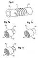
- FIG. 6shows a second embodiment wherein the tubular element 2' has end sections 2a' and 2b' with an outer diameter which is the same as that of the flexible section.
- the tubular element 2'can have an outer diameter of 5.5 mm
- the tubular element 2 of the first embodimentcan have an outer diameter of the flexible section 7.5 mm and that of the end sections of 5 mm.
- FIGs 7a) to Figures 7cshow various modifications of the adapters.
- the adapters 5'are of the type of the second adapter 5. The same parts are designated with the same reference numerals.
- the adapters 5'comprise a threaded bore 10 for connection with further parts of the bone stabilization device.
- the first section 5a' of the adapterscan be shaped in various manners.
- Fig. 7ashows a quadrangular outer surface with flat edges
- Fig. 7b )shows an octagonal outer surface
- Fig. 7ca cylindrical outer surface.
- the shape of the outer surface of the first sectionis selected such that the desired strength of the connection is achieved by a combination of a form-fit (or positiv-fit) and frictional-fit connection.
- the outer diameter of the second section 5b'corresponds to the outer diameter of the second section 2b' of the tubular element.
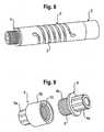
- Fig. 8shows the tubular element 2' of Fig. 6 with an adapter on either side.
- the adapter 5'corresponds to one of the adapters shown in Fig. 7a) to Fig. 7c ) and the adapter 4 corresponds to the adapter shown in Fig. 2 to 5 .
- Fig. 9shows an adapter of the type like the adapter 5, 5' and an adapter of the type like the adapter 4.
- the outer thread 7 of the adapter 4can engage with the inner thread of the threaded bore 10 of the adapter 5.
- Thisallows to combine several rod assemblies to a bone stabilization device.
- itallows to provide a spinal stabilization rod of a certain length which has different sections with different flexible properties corresponding to the flexible properties of the respective rod assemblies.
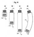
- Fig. 10a) to 10dshow various rigid rod portions 20,21,22 and 23 each heaving a threaded bore 20a,21a,22a and 23a on one end and a threaded projection 20b,21b,22b and 23b on the opposite end.
- the rigid rod portionscan have different length as shown in Figs. 10a) to 10c ) or can have a curvature as shown in Fig. 10d .
- the threaded bore 20a to 23aengages with the thread 7 of the first adapter of the rod assembly and the threaded projection 20b to 23b engages with the threaded bore 10 of the second adapter 5.
- the rigid rod portionsare made of a biocompatible material, for example of titanium or stainless steel.
- Fig. 11 a) to 11c)show examples of different spinal stabilization rods which are composed of several elements described before.
- Fig. 11ashows a spinal stabilization device before it is assembled which comprises a rigid rod portion 23, a rod assembly 1 of a specific length and specific elasticity, a further rigid rod portion 20 and a second rod assembly 1' which may have different characteristics than the first rod assembly 1.
- a rounded cap 25is provided at the end of the stabilization device which engages with the end of the rod assembly.
- Fig. 11b )shows the bone stabilization device of Fig. 11a ) in an assembled state.
- Fig. 11cshows a similar bone stabilization device as that shown in Figures 11a) and 11b ).
- the only differenceis that instead of the second rod assembly 1' a rod assembly 1" is used which has a smaller outer diameter than the first rod assembly 1 so that it is flush with the surface of the rigid rod section 20.
- the core 8can have a non circular cross section, for example a rectangular cross section, to provide an enhanced stiffness in an oriented manner.
- the core 8can be made of other materials than of a shape-memory alloy.
- itcan be made of biocompatible plastic material.
- a set of rod assemblies of various outer diameters, various elastic or flexible properties, various lengths and various means for connectionis provided.
- a set of adapters of different types and of rigid rod portions of different length and/or curvaturesis provided.
- the rod assembly, the adapters and the rigid rod portionsform a modular rod system.
- the surgeoncan select from this modular system the suitable elements to combine them to a spinal stabilization rod which can be connected to bone anchoring elements as shown in Fig. 1 .
- different anatomical situationsfor example on the left side or on the right side of the spine or in different regions of the spine can be taken into account by selecting and combining the suitable elements for correction.
Landscapes
- Health & Medical Sciences (AREA)
- Orthopedic Medicine & Surgery (AREA)
- Life Sciences & Earth Sciences (AREA)
- Surgery (AREA)
- Neurology (AREA)
- Heart & Thoracic Surgery (AREA)
- Engineering & Computer Science (AREA)
- Biomedical Technology (AREA)
- Nuclear Medicine, Radiotherapy & Molecular Imaging (AREA)
- Medical Informatics (AREA)
- Molecular Biology (AREA)
- Animal Behavior & Ethology (AREA)
- General Health & Medical Sciences (AREA)
- Public Health (AREA)
- Veterinary Medicine (AREA)
- Surgical Instruments (AREA)
- Prostheses (AREA)
Description
- The invention relates to a modular rod system including at least a first rod assembly for spinal stabilization. The first rod assembly comprises a flexible tubular element and a core arranged within the flexible tubular element and an adapter on at least one side of the flexible tubular element. The adapter allows the tubular element to be connected to other rod portions or other rod assemblies of a spinal stabilization device. At least one end of the core is freely movable. It extends into a portion of the adapter which itself extends into the tubular element, thus providing a compact design.
WO 03/047442 A1 US 2005/0085815 A1 describes a spinal stabilization rod comprising a core which is accommodated in a flexible tubular rod with tolerance in the axial direction.US 2007/0049937 A1 describes a spinal stabilization rod comprising a flexible tubular portion and a rigid end portion on either side of the flexible tubular portion and a core extending through the flexible portion and at least a part of the rigid end portions. The core can be fixed on one side and is freely movable on the other side.US 2005/0154390 A1 describes a flexible element which may comprise a core and two rod-like adapters being connectable to each end of the flexible element. The core does not extend into the adapter.Fig. 1 shows a schematic representation of the spinal column together withbone anchoring elements 100 anchored, for example, in the pedicle of thevertebrae 101. Usually the bone anchoring elements are connected through a spinal stabilization rod which may be rigid (straight or curved) or flexible to some extent. As can be seen, the distance to be bridged by the rod between two bone anchoring elements is in the order of 25 to 30 mm in the higher thoracic region and decreases to 20 to 25 mm in the mid lumbar region until around 10 to 15 mm in the lower lumbar region. In specific clinical applications it may be necessary to stabilize different portions of the spine in a different manner, for example it may be necessary to use rigid as well as flexible stabilization at different locations. It may even be necessary to use a flexible stabilization with a different degree of flexibility at different locations of the spine, for example, on the right side and the left side. When considering the small distance between the bone anchoring elements in the lower lumbar part of the spine or in the cervical part of the spine, a compact shape and small dimensions of the stabilization rod or rod parts become necessary.WO 2005/094704 A1 discloses a rod assembly for spinal stabilization, comprising a flexible tubular element having a first end section and a second end section, an adapter connected to the second end section, the adapter having an engagement structure for connection to other rod portions or other rod assemblies of a spinal stabilization device,
wherein at least a portion of the adapter extends into or onto the second end section,
a longitudinal core extending through the tubular element,
the core having a first end extending through at least a portion of the first end section
and a second end being freely movable.- It is therefore an object of the invention to provide a rod assembly for spinal stabilization which can be used in a modular manner to allow a simple and versatile use and which has small dimensions.
- The object is solved by a modular rod system according to
claim 1. Further developments are given in the dependent claims. - An advantage of the invention is that the modular rod system can be preassembled in various combinations of flexible tubular elements which form the flexible rod part and adapters in order to connect it with other rod assemblies or with rigid rod parts. This modular design enables treatment of spinal disorders in a manner most adapted to the specific clinical requirements of a patient.
- Due to the compact design it is possible to use the rod assembly in all regions of the spine, i.e. also in those regions where the bone anchoring elements used have a very small distance from each others, such as the lower lumbar region or the cervical region.
- Further features and advantages of the invention will become apparent from the detailed description of embodiments in conjunction with the accompanying drawings.
- In the drawings:
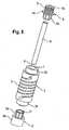
Fig. 1 shows a schematic view of the spinal column.Fig. 2 shows a sectional view of the rod assembly along the rod axis.Fig. 3a ) shows a sectional view of the rod assembly along the line A-A shown inFig. 2 .Fig. 3b ) shows a perspective view of an element of the rod assembly according toFig. 1 .Fig. 4 shows a side view of the rod assembly ofFig. 2 .Fig. 5 shows a perspective exploded view of the rod assembly ofFig. 2 .Fig. 6 shows a second embodiment of the tubular element of the rod assembly.Fig. 7a) to 7c ) show modifications of the adapter to be used with the tubular element according toFig. 6 .Fig. 8 shows a third embodiment of the rod assembly.Fig. 9 shows a perspective view of two adapters to be used with the rod assembly ofFig. 8 .Fig. 10a) to 10d ) show various embodiments of rigid rod adapters to be used with a rod assembly according to the invention.Fig. 11a) to 11c ) show various combinations of rod assemblies and adapters.- As shown in
Figures 2 to 5 the rod assembly according to a first embodiment comprises atubular element 2 having afirst end section 2a and asecond end section 2b opposite to the first end section. The inner diameter of the tubular element is in the embodiment shown constant from thefirst end section 2a to the second end section 2d. The outer diameter of the tubular element is smaller in the first and the second end section compared to the portion in between the end sections. The tubular element comprises a flexible section which provides bending and compression elasticity to the tubular element. - Preferably, the flexible section is formed by a
recess 3 extending in a helix-shaped manner over a length of thetubular element 2. Therecess 3 imparts compression and bending elasticity to thetubular element 2. The dimension and pitch of the helix-shaped recess 3 as well as the wall thickness of thetubular element 2 is such that a desired elasticity is obtained. Therecess 3 needs not to have a continuous helix shape, it can also be formed in an stepped manner including portions which are parallel to the longitudinal direction of the tubular element. The pitch of the helix can vary along the length. - Preferably, the tubular element is formed of a shape-memory alloy exhibiting a shape-memory effect and super-elasticity. Particularly, the tubular element is made of a titanium-nickel alloy such as nitinol.
- The rod assembly further comprises a
first adapter 4 being connected to thefirst end section 2a and asecond adapter 5 being connected to thesecond end section 2b. As shown in particular inFig. 2 thefirst adapter 4 comprises afirst section 4a which is connected to thefirst end section 2a of thetubular element 2 andsecond section 4b opposite to thefirst section 4a, asecond section 4b serving for connection with further elements of a spinal stabilization device. The outer diameter of thefirst section 4a corresponds approximately to the inner diameter of theend section 2a of thetubular element 2. As shown inFig. 5 thefirst section 4a of the first adapter has an outer surface with a polygon-shape, for example, with an octagon-shape. Thesecond section 4b has an outer surface which is structured to be engaged with further elements, in the embodiment shown, it comprises athread 6. Thefirst section 4a and thesecond section 4b are divided from each other by anannular shoulder 4c, the outer diameter of which corresponds to the outer diameter of thefirst end section 2a. Thefirst adapter 4 further comprises acoaxial bore 7 extending through it from its first end to its second end. - The
first adapter 4 is preferably made of a biocompatible metal, such as for example titanium. In the assembled state, thefirst adapter 4 is connected to thefirst end section 2a of the tubular element by means of a press-fit connection. The polygon-shape of the outer surface of thefirst section 4a of the first adapter leads to a connection which is a combination of a form-locking or positive-fit connection and a frictional connection. The type of the octagon is selected according to the desired strength of the connection. In particular, if the tubular element comprises nitinol, the press-fit connection can be established when the tubular element is in a cooled state, where the material is mainly in the martensitic state. In the martensitic state it is more easily deformable than in the austenitic state. Therefore, the polygon shape of the adapter can create a positive-fit connection in that it deforms the inner wall of the end section of the tubular element. Also, in the martensitic state the forces for assembly are reduced. - The
rod assembly 1 further comprises acore 8 which has in the embodiment shown a cylindrical shape and a diameter which is such that it can be connected by means of a press-fit connection to thefirst adapter 4. Thecore 8 is thus fixedly connected to thefirst adapter 4 and therefore to thefirst end section 2a of thetubular element 2. It extends from the end of thefirst adapter 4 to approximately the end of thesecond end section 2b. Hence, it extends fully through the elastic section of thetubular element 2. The length of thecore 8 is such that in a fully compressed state of thetubular element 2 the free end should not abut against thesecond adapter 5. The free end 9 of the core is not fixed and is therefore freely movable within thetubular element 2. Thecore 8 is preferably made of a shape-memory alloy, such as titanium nickel alloy, for example of nitinol. Particularly, it can be a nitinol wire. - The
second adapter 5 has, as can be seen inFigs. 2 and5 , afirst section 5a and asecond section 5b. Thefirst section 5a has an outer diameter which approximately corresponds to the inner diameter of thesecond end section 2b of the tubular element and has in this embodiment a polygon-shape. Thesecond section 5b has an outer diameter which corresponds to the outer diameter of thesecond section 2b of the tubular element. Thesecond section 5b comprises a structure for engagement with further elements of a bone stabilization device. In the embodiment shown, it comprises a threadedbore 10 for connection with a threaded rod part or adapter. Thesecond adapter 5 further comprises acoaxial bore 11 extending from the free end of thefirst section 5a to the bottom of the threaded bore 10. The inner diameter of thecoaxial bore 11 is larger than the outer diameter of thecore 8. When thesecond adapter 5 is connected to thetubular element 2 thecore 8 extends through a portion of thebore 11. - The
second adapter 5 is made of a biocompatible material, for example of titanium. - As can be seen in particular in
Figs. 2 and 3b ) abushing 12 is arranged between thefirst portion 5a of the second adapter and thecore 8. Thebushing 12 hasfirst portion 12a which is connected by means of a press-fit connection to thefirst section 5a of the second adapter. That means, the outer diameter of thebushing 12 in thefirst portion 12a is approximately the same as the inner diameter of thecoaxial bore 11. The end of thefirst portion 12a abuts to the end of thebore 11. Thesecond portion 12b has a diameter which is slightly smaller than the inner diameter of the tubular element. The inner diameter of the bushing is slightly larger than the outer diameter of thecore 8, so that thecore 8 can slide within the bushing. The length of the bushing is such that during flexion, the core does not slide out of the bushing. The bushing is made of a material which facilitates sliding of thecore 8. For example, it can be made of polyetheretherketone (PEEK), carbon fiber reinforced polyetheretherketone (CRF PEEK), polytetrafluoroethylene (PTFE) or other biocompatible materials suitable for bearings. Biocompatible coatings for improved bearing properties may also be used. - The
core 8 serves for stiffening the elastic tubular element. For example, without thecore 8, thetubular element 2 can undergo kinking in certain load conditions. Thecore 8 prevents such kinking. - The dimensions materials and properties of the elements of the rod assembly are selected such that a specific rod assembly has specific desired characteristics as far as the elasticity and the design of the adapters is concerned.
- Since the
core 8 should be freely movable on one side, it is necessary to provide the space for the movement of the core. By arranging the movable end of the core in at least a part of the second adapter the overall length of the rod assembly can be reduced. Also, the length of the flexible part of the rod assembly can be reduced. This makes it possible to use it, for example, in the lower lumbar part of the spine. - Various modifications of the embodiment described are possible.
Fig. 6 shows a second embodiment wherein the tubular element 2' hasend sections 2a' and 2b' with an outer diameter which is the same as that of the flexible section. For example, the tubular element 2' can have an outer diameter of 5.5 mm, whereas thetubular element 2 of the first embodiment can have an outer diameter of the flexible section 7.5 mm and that of the end sections of 5 mm. Figures 7a) to Figures 7c ) show various modifications of the adapters. The adapters 5' are of the type of thesecond adapter 5. The same parts are designated with the same reference numerals. The adapters 5' comprise a threadedbore 10 for connection with further parts of the bone stabilization device. Thefirst section 5a' of the adapters can be shaped in various manners.Fig. 7a ) shows a quadrangular outer surface with flat edges,Fig. 7b ) shows an octagonal outer surface andFig. 7c ) a cylindrical outer surface. The shape of the outer surface of the first section is selected such that the desired strength of the connection is achieved by a combination of a form-fit (or positiv-fit) and frictional-fit connection. The outer diameter of thesecond section 5b' corresponds to the outer diameter of thesecond section 2b' of the tubular element.Fig. 8 shows the tubular element 2' ofFig. 6 with an adapter on either side. The adapter 5' corresponds to one of the adapters shown inFig. 7a) to Fig. 7c ) and theadapter 4 corresponds to the adapter shown inFig. 2 to 5 .Fig. 9 shows an adapter of the type like theadapter 5, 5' and an adapter of the type like theadapter 4. As can be seen inFig. 9 theouter thread 7 of theadapter 4 can engage with the inner thread of the threaded bore 10 of theadapter 5. This allows to combine several rod assemblies to a bone stabilization device. In particular, it allows to provide a spinal stabilization rod of a certain length which has different sections with different flexible properties corresponding to the flexible properties of the respective rod assemblies.Fig. 10a) to 10d ) show variousrigid rod portions bore projection Figs. 10a) to 10c ) or can have a curvature as shown inFig. 10d . The threadedbore 20a to 23a engages with thethread 7 of the first adapter of the rod assembly and the threadedprojection 20b to 23b engages with the threaded bore 10 of thesecond adapter 5. The rigid rod portions are made of a biocompatible material, for example of titanium or stainless steel.Fig. 11 a) to 11c) show examples of different spinal stabilization rods which are composed of several elements described before.Fig. 11a ) shows a spinal stabilization device before it is assembled which comprises arigid rod portion 23, arod assembly 1 of a specific length and specific elasticity, a furtherrigid rod portion 20 and a second rod assembly 1' which may have different characteristics than thefirst rod assembly 1. At the end of the stabilization device arounded cap 25 is provided which engages with the end of the rod assembly. Of course, other designs of end caps are possible.Fig. 11b ) shows the bone stabilization device ofFig. 11a ) in an assembled state.Fig. 11c ) shows a similar bone stabilization device as that shown inFigures 11a) and 11b ). The only difference is that instead of the second rod assembly 1' arod assembly 1" is used which has a smaller outer diameter than thefirst rod assembly 1 so that it is flush with the surface of therigid rod section 20.- Further modifications are possible. Instead of threaded connections between the rod assembly and rigid rod portions other connections such as press-fit connections can be used. In a further modification the adapter has a portion which extends onto the end section of the tubular element and is fixed thereto, for example, by means of a press-fit connection. The various elements of the different embodiments can be combined with each other.
- The
core 8 can have a non circular cross section, for example a rectangular cross section, to provide an enhanced stiffness in an oriented manner. Furthermore, thecore 8 can be made of other materials than of a shape-memory alloy. For example, it can be made of biocompatible plastic material. - In use a set of rod assemblies of various outer diameters, various elastic or flexible properties, various lengths and various means for connection is provided. Further, a set of adapters of different types and of rigid rod portions of different length and/or curvatures is provided. The rod assembly, the adapters and the rigid rod portions form a modular rod system. The surgeon can select from this modular system the suitable elements to combine them to a spinal stabilization rod which can be connected to bone anchoring elements as shown in
Fig. 1 . In particular, different anatomical situations, for example on the left side or on the right side of the spine or in different regions of the spine can be taken into account by selecting and combining the suitable elements for correction.
Claims (17)
- Modular rod system including at least a first rod assembly for spinal stablization and a rod portion or another rod assembly of a spinal stabilization device, said first rod assembly comprising
a flexible tubular element (2, 2') having a first end section (2a) and a second end section (2b),
an adapter (4, 5) connected to the second end section (2b), the adapter (4, 5) having an engagement structure (10, 6) for connection to the rod portion or other rod assembly, the engagement structure (10, 6) comprising at the side of the adapter opposite to the second end section (2b) a threaded connection (10, 6) or a press-fit connection between the first rod assembly and the rod portion or other rod assembly,
wherein at least a portion (5a) of the adapter (4, 5) extends into or onto the second end section (2b),
a longitudinal core (8) extending through the tubular element,
the core having a first end extending through at least a portion of the first end section (2a),
and a second end (9) extending into the portion (5a) of the adapter and being freely movable therein. - The modular rod system of claim 1, wherein the adapter (5) comprises a tubular portion (5a) extending into the second end section (2b) of the tubular element.
- The modular rod system of claim 1 or 2, wherein around the second end (9) of the core a bushing (12) is provided facilitating sliding of the second end (9) of the core.
- The modular rod system of claim 3, wherein the bushing comprises polyetheretherketone (PEEK) or carbon fiber reinforced polyetheretherketone (CFR PEEK).
- The modular rod system of one of claims 1 to 4, wherein the first end of the core is fixed to the first end section (2a) .
- The modular rod system of one of claims 1 to 5, wherein the adapter (5) which is connected to the second end section (2b) is a second adapter and wherein a first adapter (4) is connected to the first end section (2a).
- The modular rod system of claim 6, wherein the first adapter (4) comprises a tubular portion (4a) extending into the first end section (2a) of the tubular element (2).
- The modular rod system of one of claims 2 to 7, wherein the tubular portion (5a) of the second adapter (5) has an outer cylindrical or polygon-shaped surface.
- The modular rod system of one of claims 7 or 8, wherein the tubular portion (4a) of the first adapter has a cylindrical or polygon-shaped surface.
- The modular rod system of one of claims 1 to 9, wherein the first (4) and/or the second adapter (5) are connected to the tubular element (2, 2') by means of a press-fit connection.
- The modular rod system of one of claims 1 to 10, wherein the first (4) and/or the second adapter (5) have at its side opposite to the first end section (2a) or the second end section (2b), respectively, said threaded connection.
- The modular rod system of one of claims 1 to 11,wherein a third adapter (20, 21, 22, 23) is provided for connecting the first (4) or the second adapter (5) to a first (4) or a second adapter (5) of another rod assembly (1, 1', 1'').
- The modular rod system of one of claims 6 to 12, wherein the core (8) is fixed to the first adapter (4) by means of a press-fit connection.
- The modular rod system of one of claims 1 to 13, wherein the core (8) is made of a shape- memory alloy, preferably of nitinol.
- The modular rod system of one of claims 1 to 14, wherein the tubular element (2, 2') is made of a shape-memory alloy, preferably of nitinol.
- The modular rod system of one of claims 1 to 15, wherein the tubular element (2, 2') has a continuous or stepped spiral recess (3) in its wall to provide elasticity.
- The modular rod system of one of claims 1 to 16, wherein the adapter (4, 5) and the tubular element (2, 2') have the same maximum outer diameter or a different maximum outer diameter.
Priority Applications (9)
| Application Number | Priority Date | Filing Date | Title |
|---|---|---|---|
| ES11004688TES2417013T3 (en) | 2007-10-11 | 2007-10-11 | Rod assembly and modular rod system for spine stabilization |
| ES07019940TES2374577T3 (en) | 2007-10-11 | 2007-10-11 | MODULAR VARILLA SYSTEM FOR THE STABILIZATION OF THE VERTEBRAL COLUMN. |
| EP11004688AEP2364656B1 (en) | 2007-10-11 | 2007-10-11 | Rod assembly and modular rod system for spinal stabilization |
| EP07019940AEP2047810B1 (en) | 2007-10-11 | 2007-10-11 | Modular rod system for spinal stabilization |
| JP2008260609AJP5151887B2 (en) | 2007-10-11 | 2008-10-07 | Rod assembly and modular rod system for spinal stabilization |
| CN2008101689622ACN101416901B (en) | 2007-10-11 | 2008-10-07 | Rod assembly and modular rod system for spinal stabilization |
| TW097138482ATWI452994B (en) | 2007-10-11 | 2008-10-07 | Rod assembly and modular rod system for spinal stabilization |
| KR1020080098267AKR20090037314A (en) | 2007-10-11 | 2008-10-07 | Rod assembly and modular rod system for spine stabilization |
| US12/249,855US9089369B2 (en) | 2007-10-11 | 2008-10-10 | Rod assembly and modular rod system for spinal stabilization |
Applications Claiming Priority (1)
| Application Number | Priority Date | Filing Date | Title |
|---|---|---|---|
| EP07019940AEP2047810B1 (en) | 2007-10-11 | 2007-10-11 | Modular rod system for spinal stabilization |
Related Child Applications (1)
| Application Number | Title | Priority Date | Filing Date |
|---|---|---|---|
| EP11004688.5Division-Into | 2011-06-08 |
Publications (2)
| Publication Number | Publication Date |
|---|---|
| EP2047810A1 EP2047810A1 (en) | 2009-04-15 |
| EP2047810B1true EP2047810B1 (en) | 2011-09-28 |
Family
ID=39167566
Family Applications (2)
| Application Number | Title | Priority Date | Filing Date |
|---|---|---|---|
| EP07019940ANot-in-forceEP2047810B1 (en) | 2007-10-11 | 2007-10-11 | Modular rod system for spinal stabilization |
| EP11004688ANot-in-forceEP2364656B1 (en) | 2007-10-11 | 2007-10-11 | Rod assembly and modular rod system for spinal stabilization |
Family Applications After (1)
| Application Number | Title | Priority Date | Filing Date |
|---|---|---|---|
| EP11004688ANot-in-forceEP2364656B1 (en) | 2007-10-11 | 2007-10-11 | Rod assembly and modular rod system for spinal stabilization |
Country Status (7)
| Country | Link |
|---|---|
| US (1) | US9089369B2 (en) |
| EP (2) | EP2047810B1 (en) |
| JP (1) | JP5151887B2 (en) |
| KR (1) | KR20090037314A (en) |
| CN (1) | CN101416901B (en) |
| ES (2) | ES2374577T3 (en) |
| TW (1) | TWI452994B (en) |
Families Citing this family (81)
| Publication number | Priority date | Publication date | Assignee | Title |
|---|---|---|---|---|
| US7833250B2 (en) | 2004-11-10 | 2010-11-16 | Jackson Roger P | Polyaxial bone screw with helically wound capture connection |
| US8292926B2 (en) | 2005-09-30 | 2012-10-23 | Jackson Roger P | Dynamic stabilization connecting member with elastic core and outer sleeve |
| US10729469B2 (en) | 2006-01-09 | 2020-08-04 | Roger P. Jackson | Flexible spinal stabilization assembly with spacer having off-axis core member |
| US10258382B2 (en) | 2007-01-18 | 2019-04-16 | Roger P. Jackson | Rod-cord dynamic connection assemblies with slidable bone anchor attachment members along the cord |
| US7862587B2 (en) | 2004-02-27 | 2011-01-04 | Jackson Roger P | Dynamic stabilization assemblies, tool set and method |
| US8353932B2 (en) | 2005-09-30 | 2013-01-15 | Jackson Roger P | Polyaxial bone anchor assembly with one-piece closure, pressure insert and plastic elongate member |
| US8876868B2 (en) | 2002-09-06 | 2014-11-04 | Roger P. Jackson | Helical guide and advancement flange with radially loaded lip |
| US7621918B2 (en) | 2004-11-23 | 2009-11-24 | Jackson Roger P | Spinal fixation tool set and method |
| US7377923B2 (en) | 2003-05-22 | 2008-05-27 | Alphatec Spine, Inc. | Variable angle spinal screw assembly |
| US7776067B2 (en) | 2005-05-27 | 2010-08-17 | Jackson Roger P | Polyaxial bone screw with shank articulation pressure insert and method |
| US7766915B2 (en) | 2004-02-27 | 2010-08-03 | Jackson Roger P | Dynamic fixation assemblies with inner core and outer coil-like member |
| US8366753B2 (en) | 2003-06-18 | 2013-02-05 | Jackson Roger P | Polyaxial bone screw assembly with fixed retaining structure |
| US8092500B2 (en) | 2007-05-01 | 2012-01-10 | Jackson Roger P | Dynamic stabilization connecting member with floating core, compression spacer and over-mold |
| US8926670B2 (en) | 2003-06-18 | 2015-01-06 | Roger P. Jackson | Polyaxial bone screw assembly |
| US7967850B2 (en) | 2003-06-18 | 2011-06-28 | Jackson Roger P | Polyaxial bone anchor with helical capture connection, insert and dual locking assembly |
| US7527638B2 (en) | 2003-12-16 | 2009-05-05 | Depuy Spine, Inc. | Methods and devices for minimally invasive spinal fixation element placement |
| US7179261B2 (en) | 2003-12-16 | 2007-02-20 | Depuy Spine, Inc. | Percutaneous access devices and bone anchor assemblies |
| US11419642B2 (en) | 2003-12-16 | 2022-08-23 | Medos International Sarl | Percutaneous access devices and bone anchor assemblies |
| US11241261B2 (en) | 2005-09-30 | 2022-02-08 | Roger P Jackson | Apparatus and method for soft spinal stabilization using a tensionable cord and releasable end structure |
| US7160300B2 (en) | 2004-02-27 | 2007-01-09 | Jackson Roger P | Orthopedic implant rod reduction tool set and method |
| US8152810B2 (en) | 2004-11-23 | 2012-04-10 | Jackson Roger P | Spinal fixation tool set and method |
| JP2007525274A (en) | 2004-02-27 | 2007-09-06 | ロジャー・ピー・ジャクソン | Orthopedic implant rod reduction instrument set and method |
| US7651502B2 (en) | 2004-09-24 | 2010-01-26 | Jackson Roger P | Spinal fixation tool set and method for rod reduction and fastener insertion |
| US8926672B2 (en) | 2004-11-10 | 2015-01-06 | Roger P. Jackson | Splay control closure for open bone anchor |
| US9216041B2 (en) | 2009-06-15 | 2015-12-22 | Roger P. Jackson | Spinal connecting members with tensioned cords and rigid sleeves for engaging compression inserts |
| WO2006057837A1 (en) | 2004-11-23 | 2006-06-01 | Jackson Roger P | Spinal fixation tool attachment structure |
| US9168069B2 (en) | 2009-06-15 | 2015-10-27 | Roger P. Jackson | Polyaxial bone anchor with pop-on shank and winged insert with lower skirt for engaging a friction fit retainer |
| US8444681B2 (en) | 2009-06-15 | 2013-05-21 | Roger P. Jackson | Polyaxial bone anchor with pop-on shank, friction fit retainer and winged insert |
| US7901437B2 (en) | 2007-01-26 | 2011-03-08 | Jackson Roger P | Dynamic stabilization member with molded connection |
| US8105368B2 (en) | 2005-09-30 | 2012-01-31 | Jackson Roger P | Dynamic stabilization connecting member with slitted core and outer sleeve |
| US7815663B2 (en) | 2006-01-27 | 2010-10-19 | Warsaw Orthopedic, Inc. | Vertebral rods and methods of use |
| EP1815812B1 (en)* | 2006-02-03 | 2009-07-29 | Spinelab AG | Spinal implant |
| CA2670988C (en) | 2006-12-08 | 2014-03-25 | Roger P. Jackson | Tool system for dynamic spinal implants |
| US8475498B2 (en) | 2007-01-18 | 2013-07-02 | Roger P. Jackson | Dynamic stabilization connecting member with cord connection |
| US8366745B2 (en) | 2007-05-01 | 2013-02-05 | Jackson Roger P | Dynamic stabilization assembly having pre-compressed spacers with differential displacements |
| US10842535B2 (en)* | 2007-02-14 | 2020-11-24 | William R. Krause | Flexible spine components having multiple slots |
| US8979904B2 (en) | 2007-05-01 | 2015-03-17 | Roger P Jackson | Connecting member with tensioned cord, low profile rigid sleeve and spacer with torsion control |
| US10383660B2 (en) | 2007-05-01 | 2019-08-20 | Roger P. Jackson | Soft stabilization assemblies with pretensioned cords |
| US20110172708A1 (en)* | 2007-06-22 | 2011-07-14 | Simpirica Spine, Inc. | Methods and systems for increasing the bending stiffness of a spinal segment with elongation limit |
| US9232968B2 (en) | 2007-12-19 | 2016-01-12 | DePuy Synthes Products, Inc. | Polymeric pedicle rods and methods of manufacturing |
| KR100837108B1 (en)* | 2008-01-11 | 2008-06-11 | 최길운 | Flexible Rod for Spinal Fixation |
| US8034083B2 (en)* | 2008-05-01 | 2011-10-11 | Custom Spine, Inc. | Artificial ligament assembly |
| AU2010260521C1 (en) | 2008-08-01 | 2013-08-01 | Roger P. Jackson | Longitudinal connecting member with sleeved tensioned cords |
| US20100049252A1 (en)* | 2008-08-21 | 2010-02-25 | Southern Spine, Llc | Transverse Connector Device for Extending an Existing Spinal Fixation System |
| US8641734B2 (en) | 2009-02-13 | 2014-02-04 | DePuy Synthes Products, LLC | Dual spring posterior dynamic stabilization device with elongation limiting elastomers |
| US8118840B2 (en) | 2009-02-27 | 2012-02-21 | Warsaw Orthopedic, Inc. | Vertebral rod and related method of manufacture |
| US9668771B2 (en) | 2009-06-15 | 2017-06-06 | Roger P Jackson | Soft stabilization assemblies with off-set connector |
| US11229457B2 (en) | 2009-06-15 | 2022-01-25 | Roger P. Jackson | Pivotal bone anchor assembly with insert tool deployment |
| CN103826560A (en) | 2009-06-15 | 2014-05-28 | 罗杰.P.杰克逊 | Polyaxial Bone Anchor with Socket Stem and Winged Inserts with Friction Fit Compression Collars |
| US8998959B2 (en) | 2009-06-15 | 2015-04-07 | Roger P Jackson | Polyaxial bone anchors with pop-on shank, fully constrained friction fit retainer and lock and release insert |
| US9320543B2 (en) | 2009-06-25 | 2016-04-26 | DePuy Synthes Products, Inc. | Posterior dynamic stabilization device having a mobile anchor |
| US9011494B2 (en) | 2009-09-24 | 2015-04-21 | Warsaw Orthopedic, Inc. | Composite vertebral rod system and methods of use |
| EP2485654B1 (en) | 2009-10-05 | 2021-05-05 | Jackson P. Roger | Polyaxial bone anchor with non-pivotable retainer and pop-on shank, some with friction fit |
| US8702758B2 (en)* | 2009-12-31 | 2014-04-22 | Industrial Technology Research Institute | Flexible spine fixing structure |
| TWI388308B (en)* | 2009-12-31 | 2013-03-11 | Ind Tech Res Inst | Flexible spinal fixation |
| US9445844B2 (en)* | 2010-03-24 | 2016-09-20 | DePuy Synthes Products, Inc. | Composite material posterior dynamic stabilization spring rod |
| KR100980313B1 (en)* | 2010-06-14 | 2010-09-06 | 주식회사 디오메디칼 | A rod for spinal fixation |
| AU2011299558A1 (en) | 2010-09-08 | 2013-05-02 | Roger P. Jackson | Dynamic stabilization members with elastic and inelastic sections |
| US20120116458A1 (en)* | 2010-11-08 | 2012-05-10 | Warsaw Orthopedic, Inc. | Modular pivotable screw assembly and method |
| US9144506B2 (en)* | 2011-08-11 | 2015-09-29 | Jeff Phelps | Interbody axis cage |
| US20130090690A1 (en)* | 2011-10-06 | 2013-04-11 | David A. Walsh | Dynamic Rod Assembly |
| US8911479B2 (en) | 2012-01-10 | 2014-12-16 | Roger P. Jackson | Multi-start closures for open implants |
| CN103565502B (en)* | 2012-07-25 | 2015-11-25 | 上海微创骨科医疗科技有限公司 | A kind of spinal column dynamic connection rod |
| US9339306B2 (en) | 2012-08-29 | 2016-05-17 | K2M, Inc. | Adjustable axial spinal rod connector |
| US9931140B2 (en) | 2012-08-30 | 2018-04-03 | K2M, Inc. | Multi-planar axial spinal rod connector |
| US8911478B2 (en) | 2012-11-21 | 2014-12-16 | Roger P. Jackson | Splay control closure for open bone anchor |
| EP2740427B1 (en) | 2012-12-05 | 2020-03-11 | Biedermann Technologies GmbH & Co. KG | Dynamic bone anchor and method of manufacturing the same |
| US10058354B2 (en) | 2013-01-28 | 2018-08-28 | Roger P. Jackson | Pivotal bone anchor assembly with frictional shank head seating surfaces |
| US8852239B2 (en) | 2013-02-15 | 2014-10-07 | Roger P Jackson | Sagittal angle screw with integral shank and receiver |
| US9566092B2 (en) | 2013-10-29 | 2017-02-14 | Roger P. Jackson | Cervical bone anchor with collet retainer and outer locking sleeve |
| US9717533B2 (en) | 2013-12-12 | 2017-08-01 | Roger P. Jackson | Bone anchor closure pivot-splay control flange form guide and advancement structure |
| US9451993B2 (en) | 2014-01-09 | 2016-09-27 | Roger P. Jackson | Bi-radial pop-on cervical bone anchor |
| US9597119B2 (en) | 2014-06-04 | 2017-03-21 | Roger P. Jackson | Polyaxial bone anchor with polymer sleeve |
| US10064658B2 (en) | 2014-06-04 | 2018-09-04 | Roger P. Jackson | Polyaxial bone anchor with insert guides |
| CN105816227A (en)* | 2015-01-05 | 2016-08-03 | 财团法人金属工业研究发展中心 | Bone fixing device |
| EP3097877B1 (en)* | 2015-05-29 | 2019-04-17 | Mega Spine Medical Co., Ltd. | Spring elastic device that links fixed components on more than two levels of bone |
| US10639078B2 (en)* | 2015-11-17 | 2020-05-05 | Warsaw Orthopedic, Inc. | Spinal implant system and method |
| CN106073875A (en)* | 2016-07-11 | 2016-11-09 | 李照文 | Universal flexible rod |
| RU2644750C1 (en)* | 2017-04-19 | 2018-02-13 | Закрытое акционерное общество "КИМПФ" ЗАО "КИМПФ" | Dynamic device for correcting scoliotic deformity of the spine and method of its application |
| US11583318B2 (en) | 2018-12-21 | 2023-02-21 | Paradigm Spine, Llc | Modular spine stabilization system and associated instruments |
| US11723691B2 (en)* | 2019-12-25 | 2023-08-15 | Apifix Ltd | Biasing device for spinal device |
Family Cites Families (45)
| Publication number | Priority date | Publication date | Assignee | Title |
|---|---|---|---|---|
| US4289123A (en) | 1980-03-31 | 1981-09-15 | Dunn Harold K | Orthopedic appliance |
| US4553273A (en) | 1983-11-23 | 1985-11-19 | Henry Ford Hospital | Vertebral body prosthesis and spine stabilizing method |
| FR2709246B1 (en) | 1993-08-27 | 1995-09-29 | Martin Jean Raymond | Dynamic implanted spinal orthosis. |
| FR2717370A1 (en)* | 1994-03-18 | 1995-09-22 | Moreau Patrice | Intervertebral stabilising prosthesis for spinal reinforcement inserted during spinal surgery |
| US7582012B2 (en)* | 2000-08-25 | 2009-09-01 | Walker Digital, Llc | Methods and apparatus for lottery game play aggregation |
| FR2827498B1 (en) | 2001-07-18 | 2004-05-14 | Frederic Fortin | FLEXIBLE VERTEBRAL CONNECTION DEVICE CONSISTING OF PALLIANT ELEMENTS OF THE RACHIS |
| IL162363A0 (en) | 2001-12-07 | 2005-11-20 | Mathys Medizinaltechnik Ag | Damping element |
| DE10236691B4 (en) | 2002-08-09 | 2005-12-01 | Biedermann Motech Gmbh | Dynamic stabilization device for bones, in particular for vertebrae |
| FR2844180B1 (en) | 2002-09-11 | 2005-08-05 | Spinevision | CONNECTING ELEMENT FOR THE DYNAMIC STABILIZATION OF A SPINAL FIXING SYSTEM AND SPINAL FASTENING SYSTEM COMPRISING SUCH A MEMBER |
| US20050171543A1 (en) | 2003-05-02 | 2005-08-04 | Timm Jens P. | Spine stabilization systems and associated devices, assemblies and methods |
| US7815665B2 (en) | 2003-09-24 | 2010-10-19 | N Spine, Inc. | Adjustable spinal stabilization system |
| US20050203513A1 (en) | 2003-09-24 | 2005-09-15 | Tae-Ahn Jahng | Spinal stabilization device |
| US7137985B2 (en) | 2003-09-24 | 2006-11-21 | N Spine, Inc. | Marking and guidance method and system for flexible fixation of a spine |
| WO2005030067A1 (en)* | 2003-09-29 | 2005-04-07 | Synthes Gmbh | Damping element |
| DE10348329B3 (en) | 2003-10-17 | 2005-02-17 | Biedermann Motech Gmbh | Rod-shaped element used in spinal column and accident surgery for connecting two bone-anchoring elements comprises a rigid section and an elastic section that are made in one piece |
| US8632570B2 (en) | 2003-11-07 | 2014-01-21 | Biedermann Technologies Gmbh & Co. Kg | Stabilization device for bones comprising a spring element and manufacturing method for said spring element |
| US7815664B2 (en)* | 2005-01-04 | 2010-10-19 | Warsaw Orthopedic, Inc. | Systems and methods for spinal stabilization with flexible elements |
| FR2867057B1 (en)* | 2004-03-02 | 2007-06-01 | Spinevision | DYNAMIC BONDING ELEMENT FOR A SPINAL FIXING SYSTEM AND FIXING SYSTEM COMPRISING SUCH A CONNECTING MEMBER |
| DE102004011685A1 (en)* | 2004-03-09 | 2005-09-29 | Biedermann Motech Gmbh | Spine supporting element, comprising spiraled grooves at outer surface and three plain areas |
| FR2868285B1 (en)* | 2004-03-30 | 2006-11-24 | Scient X Sa | INTERVERTEBRAL CONNECTION DEVICE WITH CONTROLLED MULTIDIRECTIONAL MOVEMENTS |
| US7833256B2 (en)* | 2004-04-16 | 2010-11-16 | Biedermann Motech Gmbh | Elastic element for the use in a stabilization device for bones and vertebrae and method for the manufacture of such elastic element |
| US7744634B2 (en)* | 2004-06-15 | 2010-06-29 | Warsaw Orthopedic, Inc. | Spinal rod system |
| US7854752B2 (en) | 2004-08-09 | 2010-12-21 | Theken Spine, Llc | System and method for dynamic skeletal stabilization |
| DE102004048938B4 (en) | 2004-10-07 | 2015-04-02 | Synthes Gmbh | Device for the dynamic stabilization of vertebral bodies |
| WO2006066053A1 (en) | 2004-12-15 | 2006-06-22 | Stryker Spine | Spinal rods having segments of different elastic properties and methods of using them |
| US7604654B2 (en) | 2005-02-22 | 2009-10-20 | Stryker Spine | Apparatus and method for dynamic vertebral stabilization |
| US7556639B2 (en)* | 2005-03-03 | 2009-07-07 | Accelerated Innovation, Llc | Methods and apparatus for vertebral stabilization using sleeved springs |
| US20060212033A1 (en) | 2005-03-03 | 2006-09-21 | Accin Corporation | Vertebral stabilization using flexible rods |
| US20060264937A1 (en) | 2005-05-04 | 2006-11-23 | White Patrick M | Mobile spine stabilization device |
| US20060264935A1 (en) | 2005-05-04 | 2006-11-23 | White Patrick M | Orthopedic stabilization device |
| US7811309B2 (en)* | 2005-07-26 | 2010-10-12 | Applied Spine Technologies, Inc. | Dynamic spine stabilization device with travel-limiting functionality |
| DE602005007223D1 (en) | 2005-08-24 | 2008-07-10 | Biedermann Motech Gmbh | Rod-shaped element for use in spine or trauma surgery and stabilization device with such an element |
| US7927359B2 (en)* | 2005-10-06 | 2011-04-19 | Paradigm Spine, Llc | Polyaxial screw |
| US8518084B2 (en)* | 2006-01-24 | 2013-08-27 | Biedermann Technologies Gmbh & Co. Kg | Connecting rod with external flexible element |
| DE102006003374A1 (en)* | 2006-01-24 | 2007-07-26 | Biedermann Motech Gmbh | Connecting rod with outer flexible element |
| EP1815812B1 (en) | 2006-02-03 | 2009-07-29 | Spinelab AG | Spinal implant |
| US7942905B2 (en)* | 2006-04-20 | 2011-05-17 | Warsaw Orthopedic, Inc. | Vertebral stabilizer |
| US7806913B2 (en) | 2006-08-16 | 2010-10-05 | Depuy Spine, Inc. | Modular multi-level spine stabilization system and method |
| CN101573081B (en)* | 2006-12-10 | 2012-02-22 | 帕拉迪格脊骨有限责任公司 | Posterior functional dynamic stabilization system |
| CN102525623B (en)* | 2006-12-10 | 2015-04-29 | 帕拉迪格脊骨有限责任公司 | Posterior functionally dynamic stabilization system |
| US8475498B2 (en) | 2007-01-18 | 2013-07-02 | Roger P. Jackson | Dynamic stabilization connecting member with cord connection |
| US8097022B2 (en)* | 2007-02-20 | 2012-01-17 | Warsaw Orthopedic, Inc. | Flexible coupling members for spinal stabilization members |
| CA2690038C (en)* | 2007-05-31 | 2012-11-27 | Roger P. Jackson | Dynamic stabilization connecting member with pre-tensioned solid core |
| US8080038B2 (en)* | 2007-08-17 | 2011-12-20 | Jmea Corporation | Dynamic stabilization device for spine |
| US8267965B2 (en)* | 2007-10-22 | 2012-09-18 | Flexuspine, Inc. | Spinal stabilization systems with dynamic interbody devices |
- 2007
- 2007-10-11EPEP07019940Apatent/EP2047810B1/ennot_activeNot-in-force
- 2007-10-11EPEP11004688Apatent/EP2364656B1/ennot_activeNot-in-force
- 2007-10-11ESES07019940Tpatent/ES2374577T3/enactiveActive
- 2007-10-11ESES11004688Tpatent/ES2417013T3/enactiveActive
- 2008
- 2008-10-07CNCN2008101689622Apatent/CN101416901B/ennot_activeExpired - Fee Related
- 2008-10-07JPJP2008260609Apatent/JP5151887B2/ennot_activeExpired - Fee Related
- 2008-10-07KRKR1020080098267Apatent/KR20090037314A/ennot_activeCeased
- 2008-10-07TWTW097138482Apatent/TWI452994B/ennot_activeIP Right Cessation
- 2008-10-10USUS12/249,855patent/US9089369B2/ennot_activeExpired - Fee Related
Also Published As
| Publication number | Publication date |
|---|---|
| ES2374577T3 (en) | 2012-02-20 |
| US9089369B2 (en) | 2015-07-28 |
| TW200916047A (en) | 2009-04-16 |
| CN101416901B (en) | 2013-06-05 |
| US20090163953A1 (en) | 2009-06-25 |
| JP5151887B2 (en) | 2013-02-27 |
| KR20090037314A (en) | 2009-04-15 |
| EP2047810A1 (en) | 2009-04-15 |
| ES2417013T3 (en) | 2013-08-05 |
| EP2364656A1 (en) | 2011-09-14 |
| EP2364656B1 (en) | 2013-04-03 |
| CN101416901A (en) | 2009-04-29 |
| TWI452994B (en) | 2014-09-21 |
| JP2009090117A (en) | 2009-04-30 |
Similar Documents
| Publication | Publication Date | Title |
|---|---|---|
| EP2047810B1 (en) | Modular rod system for spinal stabilization | |
| JP4945195B2 (en) | Rod implant element and stabilization device | |
| JP5208426B2 (en) | Connecting rod with external flexible member | |
| EP2174610B1 (en) | Elongated implant device and vertebral stabilization device | |
| US7621940B2 (en) | Rod-like element for application in spinal or trauma surgery, and stabilization device with such a rod-like element | |
| EP2160988B1 (en) | Rod-shaped implant in particular for stabilizing the spinal column and stabilization device including such a rod-shaped implant | |
| JP5538780B2 (en) | Stabilizer for bone, especially spinal column | |
| US7601166B2 (en) | Stabilization device for the dynamic stabilization of vertebrae or bones and rod like element for such a stabilization device | |
| EP2116205B1 (en) | Rod-shaped implant, in particular for the dynamic stabilization of the spine | |
| US20100318130A1 (en) | Flexible rod assembly for spinal fixation | |
| US20130228554A1 (en) | Elastic element for the use in a stabilization device for bones and vertebrae and method for the manufacture of such elastic element | |
| US20090099608A1 (en) | Rod assembly for dynamic posterior stabilization | |
| JP2012500048A (en) | Device for stabilizing the vertebral body | |
| US9232964B2 (en) | Spinal implant set for the dynamic stabilization of the spine |
Legal Events
| Date | Code | Title | Description |
|---|---|---|---|
| PUAI | Public reference made under article 153(3) epc to a published international application that has entered the european phase | Free format text:ORIGINAL CODE: 0009012 | |
| AK | Designated contracting states | Kind code of ref document:A1 Designated state(s):AT BE BG CH CY CZ DE DK EE ES FI FR GB GR HU IE IS IT LI LT LU LV MC MT NL PL PT RO SE SI SK TR | |
| AX | Request for extension of the european patent | Extension state:AL BA HR MK RS | |
| 17P | Request for examination filed | Effective date:20090507 | |
| 17Q | First examination report despatched | Effective date:20090608 | |
| AKX | Designation fees paid | Designated state(s):CH DE ES FR GB IT LI | |
| RTI1 | Title (correction) | Free format text:MODULAR ROD SYSTEM FOR SPINAL STABILIZATION | |
| GRAP | Despatch of communication of intention to grant a patent | Free format text:ORIGINAL CODE: EPIDOSNIGR1 | |
| RAP1 | Party data changed (applicant data changed or rights of an application transferred) | Owner name:BIEDERMANN MOTECH GMBH | |
| GRAS | Grant fee paid | Free format text:ORIGINAL CODE: EPIDOSNIGR3 | |
| DAC | Divisional application: reference to earlier application (deleted) | ||
| GRAA | (expected) grant | Free format text:ORIGINAL CODE: 0009210 | |
| AK | Designated contracting states | Kind code of ref document:B1 Designated state(s):CH DE ES FR GB IT LI | |
| REG | Reference to a national code | Ref country code:GB Ref legal event code:FG4D | |
| REG | Reference to a national code | Ref country code:CH Ref legal event code:EP | |
| REG | Reference to a national code | Ref country code:CH Ref legal event code:NV Representative=s name:NOVAGRAAF INTERNATIONAL SA | |
| REG | Reference to a national code | Ref country code:DE Ref legal event code:R096 Ref document number:602007017458 Country of ref document:DE Effective date:20111124 | |
| REG | Reference to a national code | Ref country code:ES Ref legal event code:FG2A Ref document number:2374577 Country of ref document:ES Kind code of ref document:T3 Effective date:20120220 | |
| RAP2 | Party data changed (patent owner data changed or rights of a patent transferred) | Owner name:BIEDERMANN TECHNOLOGIES GMBH & CO. KG | |
| PLBE | No opposition filed within time limit | Free format text:ORIGINAL CODE: 0009261 | |
| STAA | Information on the status of an ep patent application or granted ep patent | Free format text:STATUS: NO OPPOSITION FILED WITHIN TIME LIMIT | |
| REG | Reference to a national code | Ref country code:CH Ref legal event code:PUE Owner name:BIEDERMANN TECHNOLOGIES GMBH & CO.KG Free format text:BIEDERMANN MOTECH GMBH#BERTHA-VON-SUTTNER-STRASSE 23#78054 VS-SCHWENNINGEN (DE) -TRANSFER TO- BIEDERMANN TECHNOLOGIES GMBH & CO.KG#JOSEFSTRASSE 5#78166 DONAUESCHINGEN (DE) | |
| 26N | No opposition filed | Effective date:20120629 | |
| REG | Reference to a national code | Ref country code:DE Ref legal event code:R097 Ref document number:602007017458 Country of ref document:DE Effective date:20120629 | |
| REG | Reference to a national code | Ref country code:DE Ref legal event code:R082 Ref document number:602007017458 Country of ref document:DE Representative=s name:PRUEFER & PARTNER GBR, DE | |
| REG | Reference to a national code | Ref country code:DE Ref legal event code:R082 Ref document number:602007017458 Country of ref document:DE Representative=s name:PRUEFER & PARTNER GBR, DE Effective date:20121128 Ref country code:DE Ref legal event code:R081 Ref document number:602007017458 Country of ref document:DE Owner name:BIEDERMANN TECHNOLOGIES GMBH & CO. KG, DE Free format text:FORMER OWNER: BIEDERMANN MOTECH GMBH, 78054 VILLINGEN-SCHWENNINGEN, DE Effective date:20121128 Ref country code:DE Ref legal event code:R082 Ref document number:602007017458 Country of ref document:DE Representative=s name:PRUEFER & PARTNER MBB PATENTANWAELTE RECHTSANW, DE Effective date:20121128 | |
| REG | Reference to a national code | Ref country code:GB Ref legal event code:732E Free format text:REGISTERED BETWEEN 20130307 AND 20130313 | |
| REG | Reference to a national code | Ref country code:FR Ref legal event code:TP Owner name:BIEDERMANN TECHNOLOGIES GMBH & CO.KG, DE Effective date:20130329 | |
| REG | Reference to a national code | Ref country code:FR Ref legal event code:PLFP Year of fee payment:9 | |
| PGFP | Annual fee paid to national office [announced via postgrant information from national office to epo] | Ref country code:GB Payment date:20151026 Year of fee payment:9 Ref country code:IT Payment date:20151026 Year of fee payment:9 Ref country code:CH Payment date:20151026 Year of fee payment:9 Ref country code:DE Payment date:20151029 Year of fee payment:9 | |
| PGFP | Annual fee paid to national office [announced via postgrant information from national office to epo] | Ref country code:ES Payment date:20151023 Year of fee payment:9 Ref country code:FR Payment date:20151026 Year of fee payment:9 | |
| REG | Reference to a national code | Ref country code:DE Ref legal event code:R119 Ref document number:602007017458 Country of ref document:DE | |
| REG | Reference to a national code | Ref country code:CH Ref legal event code:PL | |
| GBPC | Gb: european patent ceased through non-payment of renewal fee | Effective date:20161011 | |
| REG | Reference to a national code | Ref country code:FR Ref legal event code:ST Effective date:20170630 | |
| PG25 | Lapsed in a contracting state [announced via postgrant information from national office to epo] | Ref country code:DE Free format text:LAPSE BECAUSE OF NON-PAYMENT OF DUE FEES Effective date:20170503 Ref country code:GB Free format text:LAPSE BECAUSE OF NON-PAYMENT OF DUE FEES Effective date:20161011 Ref country code:CH Free format text:LAPSE BECAUSE OF NON-PAYMENT OF DUE FEES Effective date:20161031 Ref country code:LI Free format text:LAPSE BECAUSE OF NON-PAYMENT OF DUE FEES Effective date:20161031 Ref country code:FR Free format text:LAPSE BECAUSE OF NON-PAYMENT OF DUE FEES Effective date:20161102 | |
| PG25 | Lapsed in a contracting state [announced via postgrant information from national office to epo] | Ref country code:IT Free format text:LAPSE BECAUSE OF NON-PAYMENT OF DUE FEES Effective date:20161011 | |
| PG25 | Lapsed in a contracting state [announced via postgrant information from national office to epo] | Ref country code:ES Free format text:LAPSE BECAUSE OF NON-PAYMENT OF DUE FEES Effective date:20161012 | |
| REG | Reference to a national code | Ref country code:ES Ref legal event code:FD2A Effective date:20180627 |