EP2046259B1 - Patient support - Google Patents
Patient supportDownload PDFInfo
- Publication number
- EP2046259B1 EP2046259B1EP07812417.9AEP07812417AEP2046259B1EP 2046259 B1EP2046259 B1EP 2046259B1EP 07812417 AEP07812417 AEP 07812417AEP 2046259 B1EP2046259 B1EP 2046259B1
- Authority
- EP
- European Patent Office
- Prior art keywords
- patient
- patient support
- support apparatus
- support deck
- foot
- Prior art date
- Legal status (The legal status is an assumption and is not a legal conclusion. Google has not performed a legal analysis and makes no representation as to the accuracy of the status listed.)
- Not-in-force
Links
- 230000000712assemblyEffects0.000claimsdescription30
- 238000000429assemblyMethods0.000claimsdescription30
- 239000004606Fillers/ExtendersSubstances0.000claimsdescription23
- 238000005259measurementMethods0.000claimsdescription3
- 230000009467reductionEffects0.000claimsdescription3
- 230000008878couplingEffects0.000description8
- 238000010168coupling processMethods0.000description8
- 238000005859coupling reactionMethods0.000description8
- 238000010276constructionMethods0.000description7
- 230000001939inductive effectEffects0.000description7
- 230000007246mechanismEffects0.000description7
- 230000007423decreaseEffects0.000description5
- 210000004712air sacAnatomy0.000description4
- 238000013461designMethods0.000description4
- 230000008901benefitEffects0.000description3
- 238000000034methodMethods0.000description3
- QVGXLLKOCUKJST-UHFFFAOYSA-Natomic oxygenChemical compound[O]QVGXLLKOCUKJST-UHFFFAOYSA-N0.000description2
- 210000002414legAnatomy0.000description2
- 239000000463materialSubstances0.000description2
- 229910052760oxygenInorganic materials0.000description2
- 239000001301oxygenSubstances0.000description2
- 238000000926separation methodMethods0.000description2
- 230000009471actionEffects0.000description1
- 210000001217buttockAnatomy0.000description1
- 238000006243chemical reactionMethods0.000description1
- 238000004891communicationMethods0.000description1
- 230000003247decreasing effectEffects0.000description1
- 230000036541healthEffects0.000description1
- 210000003127kneeAnatomy0.000description1
- 239000000314lubricantSubstances0.000description1
- 238000012986modificationMethods0.000description1
- 230000004048modificationEffects0.000description1
- 238000012544monitoring processMethods0.000description1
- NJPPVKZQTLUDBO-UHFFFAOYSA-NnovaluronChemical compoundC1=C(Cl)C(OC(F)(F)C(OC(F)(F)F)F)=CC=C1NC(=O)NC(=O)C1=C(F)C=CC=C1FNJPPVKZQTLUDBO-UHFFFAOYSA-N0.000description1
- 230000008569processEffects0.000description1
- 210000002784stomachAnatomy0.000description1
- 238000012546transferMethods0.000description1
Images


Classifications
- A—HUMAN NECESSITIES
- A61—MEDICAL OR VETERINARY SCIENCE; HYGIENE
- A61G—TRANSPORT, PERSONAL CONVEYANCES, OR ACCOMMODATION SPECIALLY ADAPTED FOR PATIENTS OR DISABLED PERSONS; OPERATING TABLES OR CHAIRS; CHAIRS FOR DENTISTRY; FUNERAL DEVICES
- A61G7/00—Beds specially adapted for nursing; Devices for lifting patients or disabled persons
- A61G7/001—Beds specially adapted for nursing; Devices for lifting patients or disabled persons with means for turning-over the patient
- A—HUMAN NECESSITIES
- A61—MEDICAL OR VETERINARY SCIENCE; HYGIENE
- A61G—TRANSPORT, PERSONAL CONVEYANCES, OR ACCOMMODATION SPECIALLY ADAPTED FOR PATIENTS OR DISABLED PERSONS; OPERATING TABLES OR CHAIRS; CHAIRS FOR DENTISTRY; FUNERAL DEVICES
- A61G7/00—Beds specially adapted for nursing; Devices for lifting patients or disabled persons
- A61G7/002—Beds specially adapted for nursing; Devices for lifting patients or disabled persons having adjustable mattress frame
- A61G7/005—Beds specially adapted for nursing; Devices for lifting patients or disabled persons having adjustable mattress frame tiltable around transverse horizontal axis, e.g. for Trendelenburg position
- A—HUMAN NECESSITIES
- A61—MEDICAL OR VETERINARY SCIENCE; HYGIENE
- A61G—TRANSPORT, PERSONAL CONVEYANCES, OR ACCOMMODATION SPECIALLY ADAPTED FOR PATIENTS OR DISABLED PERSONS; OPERATING TABLES OR CHAIRS; CHAIRS FOR DENTISTRY; FUNERAL DEVICES
- A61G7/00—Beds specially adapted for nursing; Devices for lifting patients or disabled persons
- A61G7/002—Beds specially adapted for nursing; Devices for lifting patients or disabled persons having adjustable mattress frame
- A61G7/012—Beds specially adapted for nursing; Devices for lifting patients or disabled persons having adjustable mattress frame raising or lowering of the whole mattress frame
- A—HUMAN NECESSITIES
- A61—MEDICAL OR VETERINARY SCIENCE; HYGIENE
- A61G—TRANSPORT, PERSONAL CONVEYANCES, OR ACCOMMODATION SPECIALLY ADAPTED FOR PATIENTS OR DISABLED PERSONS; OPERATING TABLES OR CHAIRS; CHAIRS FOR DENTISTRY; FUNERAL DEVICES
- A61G7/00—Beds specially adapted for nursing; Devices for lifting patients or disabled persons
- A61G7/002—Beds specially adapted for nursing; Devices for lifting patients or disabled persons having adjustable mattress frame
- A61G7/015—Beds specially adapted for nursing; Devices for lifting patients or disabled persons having adjustable mattress frame divided into different adjustable sections, e.g. for Gatch position
- A—HUMAN NECESSITIES
- A61—MEDICAL OR VETERINARY SCIENCE; HYGIENE
- A61G—TRANSPORT, PERSONAL CONVEYANCES, OR ACCOMMODATION SPECIALLY ADAPTED FOR PATIENTS OR DISABLED PERSONS; OPERATING TABLES OR CHAIRS; CHAIRS FOR DENTISTRY; FUNERAL DEVICES
- A61G7/00—Beds specially adapted for nursing; Devices for lifting patients or disabled persons
- A61G7/05—Parts, details or accessories of beds
- A61G7/053—Aids for getting into, or out of, bed, e.g. steps, chairs, cane-like supports
- A—HUMAN NECESSITIES
- A61—MEDICAL OR VETERINARY SCIENCE; HYGIENE
- A61G—TRANSPORT, PERSONAL CONVEYANCES, OR ACCOMMODATION SPECIALLY ADAPTED FOR PATIENTS OR DISABLED PERSONS; OPERATING TABLES OR CHAIRS; CHAIRS FOR DENTISTRY; FUNERAL DEVICES
- A61G7/00—Beds specially adapted for nursing; Devices for lifting patients or disabled persons
- A61G7/10—Devices for lifting patients or disabled persons, e.g. special adaptations of hoists thereto
- A61G7/104—Devices carried or supported by
- A61G7/1042—Rail systems
- A—HUMAN NECESSITIES
- A61—MEDICAL OR VETERINARY SCIENCE; HYGIENE
- A61G—TRANSPORT, PERSONAL CONVEYANCES, OR ACCOMMODATION SPECIALLY ADAPTED FOR PATIENTS OR DISABLED PERSONS; OPERATING TABLES OR CHAIRS; CHAIRS FOR DENTISTRY; FUNERAL DEVICES
- A61G7/00—Beds specially adapted for nursing; Devices for lifting patients or disabled persons
- A61G7/10—Devices for lifting patients or disabled persons, e.g. special adaptations of hoists thereto
- A61G7/104—Devices carried or supported by
- A61G7/1046—Mobile bases, e.g. having wheels
- A—HUMAN NECESSITIES
- A61—MEDICAL OR VETERINARY SCIENCE; HYGIENE
- A61G—TRANSPORT, PERSONAL CONVEYANCES, OR ACCOMMODATION SPECIALLY ADAPTED FOR PATIENTS OR DISABLED PERSONS; OPERATING TABLES OR CHAIRS; CHAIRS FOR DENTISTRY; FUNERAL DEVICES
- A61G7/00—Beds specially adapted for nursing; Devices for lifting patients or disabled persons
- A61G7/10—Devices for lifting patients or disabled persons, e.g. special adaptations of hoists thereto
- A61G7/16—Devices for lifting patients or disabled persons, e.g. special adaptations of hoists thereto converting a lying surface into a chair
- A—HUMAN NECESSITIES
- A61—MEDICAL OR VETERINARY SCIENCE; HYGIENE
- A61G—TRANSPORT, PERSONAL CONVEYANCES, OR ACCOMMODATION SPECIALLY ADAPTED FOR PATIENTS OR DISABLED PERSONS; OPERATING TABLES OR CHAIRS; CHAIRS FOR DENTISTRY; FUNERAL DEVICES
- A61G2200/00—Information related to the kind of patient or his position
- A61G2200/30—Specific positions of the patient
- A61G2200/32—Specific positions of the patient lying
- A61G2200/325—Specific positions of the patient lying prone
- A—HUMAN NECESSITIES
- A61—MEDICAL OR VETERINARY SCIENCE; HYGIENE
- A61G—TRANSPORT, PERSONAL CONVEYANCES, OR ACCOMMODATION SPECIALLY ADAPTED FOR PATIENTS OR DISABLED PERSONS; OPERATING TABLES OR CHAIRS; CHAIRS FOR DENTISTRY; FUNERAL DEVICES
- A61G2200/00—Information related to the kind of patient or his position
- A61G2200/30—Specific positions of the patient
- A61G2200/34—Specific positions of the patient sitting
- A—HUMAN NECESSITIES
- A61—MEDICAL OR VETERINARY SCIENCE; HYGIENE
- A61G—TRANSPORT, PERSONAL CONVEYANCES, OR ACCOMMODATION SPECIALLY ADAPTED FOR PATIENTS OR DISABLED PERSONS; OPERATING TABLES OR CHAIRS; CHAIRS FOR DENTISTRY; FUNERAL DEVICES
- A61G2203/00—General characteristics of devices
- A61G2203/70—General characteristics of devices with special adaptations, e.g. for safety or comfort
- A61G2203/74—General characteristics of devices with special adaptations, e.g. for safety or comfort for anti-shear when adjusting furniture
- A—HUMAN NECESSITIES
- A61—MEDICAL OR VETERINARY SCIENCE; HYGIENE
- A61G—TRANSPORT, PERSONAL CONVEYANCES, OR ACCOMMODATION SPECIALLY ADAPTED FOR PATIENTS OR DISABLED PERSONS; OPERATING TABLES OR CHAIRS; CHAIRS FOR DENTISTRY; FUNERAL DEVICES
- A61G7/00—Beds specially adapted for nursing; Devices for lifting patients or disabled persons
- A61G7/10—Devices for lifting patients or disabled persons, e.g. special adaptations of hoists thereto
- A61G7/1063—Safety means
- A61G7/1067—Safety means for adjustable bases
- A—HUMAN NECESSITIES
- A61—MEDICAL OR VETERINARY SCIENCE; HYGIENE
- A61G—TRANSPORT, PERSONAL CONVEYANCES, OR ACCOMMODATION SPECIALLY ADAPTED FOR PATIENTS OR DISABLED PERSONS; OPERATING TABLES OR CHAIRS; CHAIRS FOR DENTISTRY; FUNERAL DEVICES
- A61G7/00—Beds specially adapted for nursing; Devices for lifting patients or disabled persons
- A61G7/10—Devices for lifting patients or disabled persons, e.g. special adaptations of hoists thereto
- A61G7/1073—Parts, details or accessories
- A61G7/1076—Means for rotating around a vertical axis
Definitions
- the present inventionrelates generally to patient support apparatuses, such as beds, stretchers, cots, and the like, and more particularly to patient support apparatuses that can have their height and orientations changed.
- US 2003/0093862discloses a patient support apparatus according to the precharacterizing portion of claim 1.
- the present inventionprovides a patient support apparatus as claimed in claim 1.
- the various aspects of the present inventionprovide an improved patient support apparatus that can be used in both bariatric and non-bariatric settings.
- By coupling the support deck directly to the elevation adjustment assemblies without an intervening framesubstantial weight and cost reductions are achieved. Further, by placing the elevation adjustment assemblies outside the perimeter of the patient support deck, the support deck can be lowered to a greater extent because it is not blocked from downward movement by the structure of the elevation adjustment assemblies.
- the adjustability of the side railsallows them to be easily moved out of the way when transferring a patient to or from the bed.
- Patient support apparatus 30includes a base 32, four elevation assemblies 34a-d, a patient support deck 36, a sleep surface 38, a headboard 40 positioned at a head end 42 of patient support apparatus 30, and a footboard 44 positioned at a foot end of patient support apparatus 30.
- Base 32includes a plurality of wheels 48 and has a head end 50 and a foot end 52, both of which are oriented in the same direction as head end 42 and foot end 46, respectively, of patient support apparatus 30.
- Base 32further includes four corners 54a-d, each of which supports one of the elevation assemblies 34a-d.
- the four elevation assemblies 34a-dare adapted to raise and lower patient support deck 36 to different heights with respect to base 32. The detailed construction of the elevation assemblies will be described below with reference to FIGS. 5 & 6 .
- patient support deck 36is divided into a plurality of sections, including a head section 56, a seat section 58, and a foot section 60.
- Each sectionmay include a plate (not shown) or other flat structure positioned on top of it that helps support a mattress or other type of sleep surface on which a patient lies.
- Head section 56is configured to support the head and torso region of a patient lying on support deck 36.
- Seat section 58is configured to support the buttocks region of a patient lying on support deck 36.
- foot section 60is configured to support the foot and lower leg region (e.g. the region of the leg below the knee) of a patient lying on support deck 36.
- patient support deck 36can be varied to include a lesser or greater number of deck sections than the three illustrated in FIGS. 2-4 .
- patient support deck 36is supported by way of a pair of head end rails 62 and a pair of foot end rails 64.
- Each head end rail 62extends from head end 42 of patient support apparatus 30 to an intermediate location 66 located between head end 42 and foot end 46 of patient support apparatus 30.
- Each foot end rail 64extends from foot end 46 of patient support apparatus 30 to intermediate location 66.
- Head end rails 62 and foot end rails 64are pivotably coupled to each other at intermediate location 66 by way of one or more pivot pins 68 ( FIG. 4 ).
- each foot end rail 64is constructed of a rigid, non-extensible beam, while each head end rail 62 is comprised of a beam 70 and a sleeve 72.
- Beam 70 and sleeve 72each extend in longitudinal directions that are parallel to each other. Beam 70 is slideably received within sleeve 72 such that beam 70 can retract into or extend out of sleeve 72, thereby altering the overall length of head end rail 62.
- Beam 70may include a bent region 71, such as is shown in FIG.
- FIGS. 32a-cwhich are cross sections of one of the head end rails 62 of FIG. 4 , illustrate three different possible configurations of beam 70 and sleeve 72, although additional configurations can also be used.
- beam 70is completely enveloped by sleeve 72 and no mechanical structures are positioned between the outside perimeter of beam 70 and the inside perimeter of sleeve 72 (the distance between these two perimeters is exaggerated for clarity in FIG. 32a ).
- a suitable lubricantmay be optionally be inserted into a space 74 defined between the exterior of beam 70 and the interior of sleeve 72 to facilitate the sliding of beam 70 with respect to sleeve 72.
- one of beam 70 and sleeve 72can include a plurality of raised bearings 76 in space 74 that provide limited contact between beam 70 and sleeve 72 to thereby facilitate sliding of beam 70 with respect to sleeve 72. While FIG. 32b illustrates sleeve 72 as including the raised bearings 76, the raised bearings could alternatively be attached to beam 70. Further, the location, number, and shape of the raised bearing 76 can be varied from that depicted in FIG. 32c .
- rollers 78are sandwiched between beam 70 and sleeve 72 in space 74.
- Rollers 78may be spherical rollers, cylindrical rollers, or other types of rollers.
- Rollers 78may be held in place by one or more bearing races 80.
- the number and location of rollers 78, as well as the number, location, and configuration of bearing races 80,can be varied from that depicted in FIG. 32c .
- beam 70 and sleeve 72can be moveably coupled to each other in still other manners.
- sleeve 72could be constructed to only partially envelope beam 70.
- the rectangular cross-sectional shape of beam 70 and sleeve 72could be varied to circular, square, or other shapes. Still other variations of beam 70 and sleeve 72 can be implemented.
- head end rail 62is pivotably coupled to foot end rail 64. More specifically, in the embodiment illustrated in FIGS. 3 and 4 , foot end rail 64 is pivotably coupled to beam 70 of head end rail 62.
- the pivoting of head end rail 62 with respect to foot end rail 64is carried out by an actuator 82 ( FIGS. 3 and 4 ).
- actuator 82may take on any configuration that enables head end rails 62 and foot end rails 64 to pivot with respect to each other.
- actuator 82may be configured in the manner illustrated in FIGS. 3 and 4 .
- actuator 82includes a horizontal threaded shaft 84 to which a first pair of arms 86a,b and a second pair of arms 88a,b are attached.
- Horizontal threaded shaft 84is powered to rotate by a motor 90.
- First arms 86a and bare each attached at their foot end (i.e. the end closest to foot end 46 of patient support apparatus 30) to one of collars 92a and b, respectively.
- Second arms 88a and bare each attached at their head end (i.e. the end closest to head end 42 of patient support apparatus 30) to one of collars 92a and b, respectively.
- Collars 92a and beach include one or more internal threaded apertures that matingly couple to the exterior threads on horizontal threaded shaft 84. Collars 92a and b thereby threadingly mate arms 86a,b and 88a,b to horizontal threaded shaft 84.
- the head ends of first arms 86a and bare pivotably secured to any suitable locations underneath seat section 58 of support deck 36.
- the foot ends of second arms 88a and bare pivotably secured to any suitable locations underneath foot section 60 of support deck 36.
- actuator 82operates in the same manner as a conventional car jack, which multiplies the torque of motor 90 such that an enormous pivoting force can be created between seat section 58 and foot section 60, thereby allowing patient support apparatus 30 to sustain greater patient loads. More specifically, the operation of motor 90 causes threaded shaft 84 to turn in either of two directions. In a first direction, the rotation of threaded shaft 84 causes collars 92a and b to move horizontally toward each other along the axis defined by shaft 84. In the second, opposite direction, the rotation of threaded shaft 84 causes collars 92a and b to move horizontally away from each other along the axis defined by shaft 84.
- first arm 86a and second arm 88aWhen collars 92a and b move toward each other, the angle defined between first arm 86a and second arm 88a increases (along with the angle defined between first arm 86b and second arm 88b), causing the distance between the head ends of first arms 86a and b and the foot ends of second arms 88a and b to increase, thereby urging seat section 58 and foot section 60 toward the horizontal orientation.
- first arm 86a and second arm 88adecreases (along with the angle defined between first arm 86b and second arm 88b), causing the distance between the head ends of first arms 86 and b and the foot ends of second arms 88a and b to decrease, thereby urging seat section 58 and foot section 60 to pivot with respect to each other (more specifically, the foot end of seat section 58 and the head end of foot section 60 pivot upwardly).
- a distance B( FIG. 4 ) between head section 56 and seat section 58 also changes. More specifically, as the pivotal junction between seat section 58 and foot section 60 moves upwardly from the horizontal orientation ( FIG. 2 ) to a raised orientation (such as FIG. 4 ), distance B increases. Further, as the pivotal junction between seat section 58 and foot section 60 moves downwardly to the horizontal orientation, distance B decreases.
- the changing length of distance Boperates as a shear reduction mechanism that reduces the shear forces that would otherwise be created between the sleep surface 38 and the patient as the support deck 36 pivots.
- the pivoting of head section 56 between the horizontal orientation illustrated in FIG. 2 to a raised orientationis carried out by way of a separate actuator (not shown) that is suitably coupled between head section 56 and head end support rails 62 (or structures attached thereto). This actuator can be activated independently of actuator 82, or simultaneously therewith.
- FIGS. 5 and 6illustrate in greater detail the construction of two of the elevation assemblies 34c & d.
- elevation assembly 34cincludes a vertical threaded shaft 94c housed with a cylindrical post 96 that extends vertically upward from corner 54c of base 32.
- Vertical threaded shaft 94chas threads on its exterior surface that mate with interior threads on a collar 98c.
- Collar 98cis pivotably joined to one end of a head end horizontal beam 100.
- the other end of head end horizontal beam 100is joined to collar 98d, which is threadingly mounted onto a vertical shaft 94d (not shown) inside elevation assembly 34d.
- a motor 102Housed within base 32 at each of corners 54a-d is a motor 102.
- Each motor 102is coupled with one of the threaded shafts 94a-d in each of the elevation assemblies 34a-d. Operation of motors 102 causes their respective vertical threaded shafts 94a-d to rotate. This rotation, in turn, causes collars 98a-d to move upward or downward, depending upon the direction of rotation of threaded vertical shafts 94a-d. When collars 98c-d move upward or downward, they likewise cause head end horizontal beam 100 to move upward or downward. Similarly, when collars 98a-b move upward or downward, they likewise cause a foot end horizontal beam 104 to move upward or downward ( FIG. 1 ).
- head end horizontal beam 100causes an upward or downward movement of the head end of patient support deck 36 (i.e. the end of support deck 36 adjacent head end 42 of patient support apparatus 30).
- the upward or downward movement of foot end horizontal beam 104causes an upward or downward movement of the foot end of patient support deck 36.
- head end rails 62are each pivotably coupled by any suitable means (such as, but not limited to, a ball joint) to head end horizontal beam 100
- foot end rails 64are also each pivotably coupled by any suitable means (such as, but not limited to, a ball joint) to foot end horizontal beam 104
- Thiscauses patient support deck 36 to tilt in a longitudinal direction.
- patient support deck 36can be tilted to the Trendelenberg and reverse Trendelenberg positions, as well as other positions.
- a controllermay be provided at any suitable location on patient support apparatus 30 that controls the speed of operation of each of the motors 102.
- the controllermay include a conventional microprocessor or microcontroller, or any other suitable electronic control circuitry for controlling the speed of the motors 102 in the elevation assemblies 34a-d.
- the controllermay desirably be part of a closed loop control circuit, although open loop control circuits may also be used.
- the controllermay be a proportional-integral-derivative (PID) controller.
- PIDproportional-integral-derivative
- the controlleris configured to operate the four motors 102a-d in several different manners. In a first manner, the controller operates each of the four motors 102a-d at the same speed, causing support deck 36 to rise or fall uniformly.
- the controlleroperates the motors of elevation assemblies 34a & b at the same speed, causing the foot end of support deck 36 to rise or fall.
- the controlleroperates the motors of elevation assemblies 34c & d at the same speed, causing the head end of support deck 36 to rise or fall.
- the controlleroperates the motors of elevation assemblies 34a and 34c at the same speed, causing patient support deck 36 to tilt about its longitudinal axis (which is made possible by the ball joints, or similar joints, between the collars 98 and either bottom bar 108 or bottom bar 118 at the head end and foot ends 42 and 46, respectively, of patient support apparatus 30.
- the controlleroperates the motors of elevation assemblies 34b & d at the same speed, which also causes the patient support deck 36 to tilt about its longitudinal axis.
- the various manners of operating the motorscan be combined in any manner, and it will be understood that the controller may operate the motors in still different manners. Further, the controller need not offer all these different manners of controlling the motors 102.
- head end horizontal beam 100includes a top shaft 106 and a bottom bar 108. Head end rails 62 are pivotably coupled directly to top shaft 106.
- a flange 110is provided at each end of bottom bar 108 that includes a housing (not shown) in which a rotational axis 107 of top shaft 106 is inserted. This housing allows top shaft 106 to rotate about rotational axis 107.
- a conventional load cell 112may be positioned in between top shaft 106 and bottom bar 108. Because of the rotational freedom of top shaft 106 with respect to bottom bar 108, any weight placed upon patient support deck 36 will cause top shaft 106 to rotate in the direction indicated by arrow 109 ( FIG.
- Load cell 112measures this force and converts it into a weight measurement which may then be passed onto the controller on patient support apparatus 30, or it may be sent to any other suitable location, such as, but not limited to, a site remote from the patient support apparatus 30, such as a hospital network or a nurses station, or other location.
- Each flange 110 of bottom bar 108is coupled to one of collars 98c & d. As was mentioned previously, this coupling may be by any suitable means, such as, but not limited to, ball joints. Other types of joints may also be used. Whatever the selected coupling, space is provided for the coupling by way of a vertical slot 114 ( FIG. 6 ) defined along the interior of each of posts 96. Vertical slots 114 provide clearance for the coupling between collars 98 and flanges 110 of bottom bar 108 as head end horizontal beam 100 is raised and lowered.
- foot end horizontal beam 104is coupled to collars 98a & b in a similar manner to that of head end horizontal beam 100. More specifically, foot end horizontal beam 104 includes a top shaft 116, a bottom bar 118, and a load cell 112 sandwiched between top shaft 116 and bottom bar 118 ( FIG. 1 ). The load cell 112 of foot end horizontal beam 104 measures the weight on patient support deck 36 that is exerted on the foot end of patient support deck 36.
- both load cells 112may be transmitted to the controller on the bed, or may be sent off the bed to any other suitable location. Because of the design of patient support apparatus 30, it is only necessary to utilize two load cells 112 to determine the weight of the patient. In contrast, many beds and stretchers of the prior art have utilized three or more load cells to determine a patient's weight. The design of patient support apparatus 30 thus reduces the cost and complexity of the patient weight determination feature.
- FIG. 7illustrates one possible manner of attaching one or more generally planar side rails 120 to patient support apparatus 30.
- each side rail 120includes a horizontal pivot beam 122.
- the horizontal pivot beam 122 of a head end side rail 120ais pivotably coupled to a side beam 124 of head section 56.
- Horizontal pivot beam 122is thus free to pivot about a vertical pivot axis 126 between two orientations.
- the general vertical plane defined by head end side rail 120ais oriented parallel to the longitudinal extent of patient support apparatus 30.
- the general vertical plane defined by head end side rail 120ais oriented perpendicular to the longitudinal extent of patient support apparatus 30.
- the first orientationrepresents the "in-use” position in which the side rail 120 abuts against the side of the patient support deck 36.
- the second orientationrepresents the "out-of-the-way” position in which the side rail 120 has been pivoted away from the support deck 36 in order to allow access to patient support deck 36, such as for transferring the patient to or from patient support apparatus 30, or for other means.
- Foot end side rail 120b( FIG. 7 ) operates in a similar manner to that described above with respect to head end side rail 120a. That is, foot end side rail 120b includes a horizontal pivot beam 122 that is pivotably attached to one of foot end rails 64. The horizontal pivot beam 122 of foot end side rail 120b pivots about another vertical pivot axis 126 located generally near the foot end 46 of patient support apparatus 30. Foot end side rail 120b is likewise pivotable between two orientations: one in which it abuts against the edge of support deck 36, and another in which it is swung outwardly from patient support deck 36 to allow greater access to support deck 36.
- head end side rail 120a and foot end side rail 120bcan be swung open in a manner similar to the saloon doors commonly seen in Western movies. This type of swinging movement allows the side rails 120a and b to be moved completely out of the way, thereby providing greater access to patient support deck 36.
- additional side rails 120may also be provided on the opposite side of support deck 36. These additional side rails 120 may be constructed in the same manner as head and foot end side rails 120a & b. Alternatively, the side rails on the opposite side may be constructed to pivot and/or move in different manners.
- side rails 120a & bmay further be pivotable about a horizontal pivot axis defined by pins 128 ( FIG. 7 ).
- Pins 128are defined at the intersection of a vertical member 130 and a horizontal member 132 of side rails 120. Pins 128 enable side rails 120 to pivot between the upright orientation depicted in FIG. 7 and a lowered orientation (not shown) in which an edge 134 has moved from being positioned on the top of side rail 120 to being positioned on the bottom of side rail 120.
- side rails 120swing about the pivot axis of pins 128 such that the planar body of side rails 120 moves to an elevation generally lower than that of sleep surface 38, yet still in the same plane as that illustrated in FIG. 7 .
- Side rails 120may further be horizontally adjustable. Specifically, horizontal members 132 may be slideably attached to the underside of horizontal pivot beams 122 such that vertical members 130 can be moved further away from, or closer to, horizontal pivot beams 122. This enables the distance between side rails 120 positioned on opposite sides of support deck 36 to be adjusted. Thus, if extra space is needed on support deck 36 to accommodate a larger patient, or for other reasons, side rails 120 can be slid away from support deck 36 to create this extra space.
- the manner in which horizontal members 132 may be slidingly coupled to horizontal pivot beam 122can be varied within the scope of the present invention.
- Such a couplingmay include, but is not limited to, a sleeve-and-beam type of construction the same as, or similar to, any of the various configurations of beam 70 and sleeve 72 (including those constructions of FIGS. 32a-c ).
- horizontal members 132may be pivotably coupled to the underside of patient support deck 36 at their interior ends 136 ( FIG. 7 ). This would enable the side rails 120 to pivot between the orientation depicted in FIG. 7 and that shown in FIG. 9 .
- side rails 120have been pivoted to a lowered position suitable for transferring a patient to or from sleep surface 38. Such a pivoting takes place about a horizontal pivot axis (not shown) that extends in the direction of the longitudinal axis of the patient support apparatus 30 (i.e. in the direction from head end 42 to foot end 46, or vice versa).
- side rails 120can be coupled to support deck 36 such that they are pivotable to a flat, horizontal orientation that then allows the side rail to be slid underneath patient support deck 36.
- FIG. 11illustrates an example of this type of attachment to support deck 36.
- patient support apparatus 30includes two side rails 120 that are in the upright position, and two side rails 120 that have been pivoted and slid to the stowed position underneath support deck 36.
- This stowed positionoffers the advantages of moving the side rail completely out of the way of the patient, and also consuming very little space between support deck 36 and base 32. This latter advantage ensures that support deck 36 will still be able to be lowered to a very small height above the floor.
- side rails 120When side rails 120 are attached and pivotable in the manner illustrated in FIG. 11 , it should be noted that the side rails 120 do not interfere with the lowering of support deck 36. Stated alternatively, when the side rails 120 are in the stowed position and support deck 36 is lowered to its lowest orientation, the stowed side rails 120 will not contact either one of a pair of base beams 33.
- Base beams 33are part of base 32 and they extend longitudinally from head end 42 to foot end 46 of patient support apparatus 30. Because base beams 33 are positioned generally along the longitudinal center of patient support apparatus 30, the side rails 120, when in the stowed position, will not contact base beams 33, but will instead fit into one of spaces 35 adjacent base beams 33. Thus, side rails 120 do not create a physical limitation on the degree to which support deck 36 may be lowered.
- FIGS. 28 and 29illustrate alternative embodiments of side rails that may be attached to patient support apparatus 30.
- the side rails 320are divided into two sections: a stationary section 322 and a pivotable section 324.
- Pivotable sections 324are pivotable about vertical pivot axes 326.
- the pivotable sections 324 of adjacent side rails 320are next to each other.
- an access space 328is created between side rails 320 that provides ample room for patient ingress and egress onto patient support apparatus 30.
- pivotable sections 324can be used as handles which the patient may grip to help support himself or herself as he or she exits or enters patient support apparatus 30.
- a side rail 330may be incorporated into any of the patient support apparatuses described herein.
- Side rail 330includes a pivot point 332 that enables the side rail 330 to be pivoted between a raised orientation 334 and a lowered orientation 336.
- Side rail 330, as well as any of the other side rails discussed herein,may include a control panel 338 with one or more user-activated controls that enable either the patient or attending personnel to control various features of patient support apparatus 30.
- the features that may be controlled by control panel 338include the raising and lowering of patient support deck 36, the pivoting of the various sections of patient support deck 36, the reading of load cells 112, communications with health care personnel at remote locations (e.g. remote nurse call), and any other functions that may be desirably performed by patient support apparatus 30.
- any of the side rails 120, 320, and 330may include suitable means for securing the side rails in the different orientations to which they are pivotable.
- Such meansmay include detents, latches, or other structures that allow the side rails to be releasably held in any desirable orientation.
- the sliding of horizontal members 132 along the underside of horizontal pivot beams 122may include structures for securing horizontal members 132 at selected locations along pivot beams 122. Any conventional structures may be used for this securing.
- any of the side rails discussed hereincan be locked in any of the various orientations to which they are pivotable or otherwise moveable.
- FIG. 8depicts a support deck extender 138 that may be attached to the foot end 46 of patient support deck 36.
- Support deck extender 138includes two side beams 140 and an end beam 142 attached to each of the side beams 140 at a right angle. Foot board 44 is attached to end beam 142.
- Support deck extender 138is slideably attached to foot section 60 of support deck 36 such that extender 138 can slide in the directions indicated by double arrow 144. That is, extender 138 can slide toward foot section 60 or away from it. When slid away from foot section 60, extender 138 effectively increases the length of patient support deck 36 ( FIG. 10 illustrates extender 138 slid partially away from support deck 36).
- Extender 138may be slidingly coupled to foot section 60 in any suitable manner. In one manner, extender 138 is slidingly coupled to the underside of foot section 60 in a beam-and-sleeve type arrangement that may take on any of the various configurations discussed above regarding beam 70 and sleeve 72 (including the illustrations of FIGS. 32a-c ). Extender 138 may be coupled in still other manners to foot section 60.
- FIG. 10illustrates patient support apparatus 30 with two side rails 120 positioned on either side of head section 56 of support deck 36.
- FIG. 10also illustrates two side rails 120 positioned on either side of seat section 58 of support deck 36. While FIG. 10 does not illustrate any side rails 120 positioned on the sides of foot section 60 of support deck 36, patient support apparatus 30 may includes side rails attached to foot section 60. Such a situation is depicted in FIGS. 12 and 13 , which illustrate three side rails 120 on each side of support deck 36, for a total of six side rails 120. Each of the six side rails 120 could be replaced by any one of side rails 320 and 330, discussed above. Further, each of the six side rails illustrated in FIGS.
- side rails 120could be attached to support deck 36 such that they pivot in any of the manners discussed above with respect to side rails 120 and/or side rails 320 and 330.
- the side rails 120are pivotable and slideable to a stowed position underneath support deck 36 in which the general plane of the side rail is in a horizontal orientation.
- side rails 120may desirably be height adjustable such that a top edge 146 is positioned at least nine inches above a top face 148 of sleep surface 38.
- FIG. 10illustrates this nine inch height above top face 148 of sleep surface 38.
- the side rails 120 (or 320 or 330) adjacent head end 42 of patient support apparatus 30are preferably dimensioned such that a front side edge 149 of side rails 120 is no greater than 2.5 inches away from the adjacent post 96. This ensures that the horizontal gap between the front side edge 149 and the post 96 is no greater than 2.5 inches, which helps ensure that a patient's arms or legs do not become wedged between one of the side rails 120 and posts 96.
- any side rails 120(or 320 or 330) are attached to foot section 60 of support deck 36, such side rails may also desirably be dimensioned such that the horizontal gap between their foot side edges 150 and posts 96a & b is no greater than 2.5 inches.
- Base 32 of patient support apparatus 30may be configured to include one or more recesses in a top surface 152 of each of base corners 54a-d ( FIG. 1 ). Such recesses may be dimensioned to support various hospital equipment, such as IV poles, an oxygen canister 154 ( FIG. 1 ), medical devices, or any other structure that may desirably be attached to patient support apparatus 30.
- headboard 40 and/or footboard 44may include coupling structures for supporting oxygen canisters 154 ( FIGS. 12 & 13 ), IV poles, other hospital equipment or medical devices.
- Base 32may further include a fifth wheel (not shown) positioned in the center region of base 32 that can move between a lowered position in which it is in contact with the floor and a raised position in which it is out of contact with the floor.
- a fifth wheelcan assist in steering patient support apparatus 30 as it is pushed on wheels 48 from location to location.
- Such a fifth wheelcan be especially useful when all of wheels 48 are castered.
- FIGS. 14-19 and 24-25illustrate an alternative embodiment of a patient support apparatus 230.
- Patient support apparatus 230shares many features and components in common with patient support apparatus 30. Those components of support apparatus 230 that are the same as those of support apparatus 30 are labeled with the same reference numerals and operate in the same manner as described previously.
- patient support apparatus 230includes four posts 96a-d which house four elevation assemblies 34a-d. Each of these elevation assemblies 34a-d works in the same manner as was previously described above with respect to support apparatus 30. That is, they each include a motor 102 (not shown in FIGS. 14-19 and 24-25 ) that rotates a vertical shaft 94 (also not shown) that, depending upon the direction of rotation, will raise or lower patient support deck 36.
- FIG. 14 and 16illustrate patient support deck 36 in the lowest orientation
- FIG. 15illustrates patient support deck 36 in its highest orientation
- a controllersuch as the one described above with respect to support apparatus 30, may be included at any suitable location to control the operation of each of the motors in elevation assemblies 34a-d in the same manners described above with respect to support apparatus 30.
- the support deck 36 of patient support apparatus 230is also pivotable from the flat orientation of FIG. 14 into different orientations, one of which is illustrated in FIG. 17 . These pivotable positions are achieved by way of an actuator 156 ( FIGS. 15 & 17 ), which may be constructed in the same manner as actuator 82 described above, or in any alternative manner. As actuator 82 pivots the sections of support deck 36 to different orientations, sleeve 72 and beam 70 of head end rails 62 will retract into and extend out of each other in the manner described above. With the exception of those details of patient support apparatus 230 explicitly mentioned below, all elements of patient support apparatus 230 bearing the same reference numerals as those of patient support apparatus 30 perform the same function and operate in the same manner as described above with respect to support apparatus 30. Accordingly, no further discussion of the common elements will be necessary.
- Headboard 40 and footboard 44may both be slidingly engaged to the two posts 96 nearest them. Operation of elevation assemblies 34 simultaneously raises and lowers headboard 40 and footboard 44, which each slide within vertical tracks 238 ( FIG. 14 ) defined in the interior sides of posts 96.
- support deck 36 of patient support apparatus 230includes a plurality of width extenders 232 that slide toward and away from the center longitudinal line of support apparatus 230 in the directions indicated by double arrow 234.
- Width extenders 232allow the width of patient support deck 36 to be adjusted in order to accommodate patients of different sizes, as well as for any other reason it may be desirable to adjust the width of patient support deck 36.
- FIG. 18illustrates width extenders 232 in the extended position while FIG. 19 illustrates the width extenders 232 in the retracted position.
- Width extenders 232may retract underneath the respective deck section (56, 58, or 60) to which it is coupled, or deck sections 56, 58, and 60 may be constructed to allow extenders 232 to be slid directly into sections 56, 58, and 60 at generally the same elevation as the stationary portions of deck sections 56, 58, and 60.
- Extenders 232each include a plurality of cross beams 236 that are received within respective sleeves positioned either within or underneath deck sections 56, 58, and 60.
- the construction of the sleeves and cross beams 236may take on any suitable configuration, including such configurations as those discussed above with respect to beam 70 and sleeve 72 (including the variations of FIGS. 32a-c ).
- FIGS. 20-23illustrate one embodiment of an extendable sleep surface 38 that can be used with patient support apparatus 230 when extenders 232 are utilized.
- FIGS. 20-23illustrate an extendable sleep surface 240 having a top face 148, a bottom face 158, a pair of side edges 160, and a strip region 162 adjacent each side edge 160.
- Strip region 162contains a fold line 164 that can fold about a pivot region 166 between a folded orientation ( FIG. 20 ) and an unfolded orientation ( FIG. 21 ).
- Both sides of sleep surface 38may include a strip region 162 that is foldable between the folded and unfolded orientations, or only a single side of sleep surface 230 may include a strip region 162 that is foldable. As can be seen in FIG.
- sleep surface 240has a first width 168.
- FIG. 23which is a plan view of sleep surface in the unfolded orientation, sleep surface 240 has a second width 170 when unfolded that is greater than first width 168 when folded.
- a single sleep surface 240can thus be used with patient support apparatus 230 and the width of the sleep surface 240 can be adjusted to correspond to the width adjustments made to support deck 36 via width extender 232.
- Strip region 162may also included a stiff region 170 that is stiffer than the surrounding regions, particularly those regions near top face 148 which are desirably soft so that a patient can lie comfortably on sleep surface 240.
- Stiff region 170is relatively more rigid than these regions such that when extendable sleep surface 240 is unfolded to the orientation of FIG. 21 , stiff region 170 becomes positioned along side edge 160.
- the relative stiffness of stiff region 170helps support the outer edges 160 of sleep surface 240 against downward pressures applied to top face 148 over the areas above a gap 172 left behind by the unfolding of fold line 164.
- Extendable sleep surface 240may be made out of any suitable materials that provide suitable softness and comfort for a patient positioned on top of support deck 36.
- either or both of sleep surfaces 38 and 240may include one or more air bladders that are selectively inflatable to different levels of pressure, thereby allowing different levels of support to be provided to the patient. If more than one air bladder is provided, the air bladders may be selectively inflatable so that different ones of the air bladders can be inflated to different pressures.
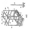
- FIGS. 24 and 25illustrate patient support apparatus 230 with an optional overhead support structure 180 attached to the tops of each of posts 96a-d.
- Overhead support structure 180includes four vertical beams 182a-d, a pair of longitudinal beams 184a & b, and a plurality of cross beams 186 interconnecting the longitudinal beams 184a & b.
- Overhead support structure 180may be used to support a variety of different items, such as a privacy canopy that partially or wholly envelopes patient support apparatus 230 for purposes of giving the patient some privacy.
- Overhead support structure 180may also be used to support an electronic display, such as a television, monitor, or screen, on which entertainment (such as television channels) may be displayed, or through which the Internet may be accessed, or through which video teleconferencing with remotely located medical personnel may take place.
- a cameramay also optionally be positioned on overhead support structure 180 to allow video monitoring of the patient, or for video teleconferencing. Still further, overhead support structure 180 may be used to support or hold various medical equipment.
- overhead support structure 180supports a patient proning apparatus 188.
- Patient proning apparatus 188may be coupled together with either patient support apparatus 30 or patient support apparatus 230.
- Patient proning apparatus 188includes a patient sleeve 190 that wraps under and around a patient in the manner illustrated more clearly in FIG. 26 .
- Patient sleeve 190is supported by an overhead beam 192 ( FIG. 26 ), which may be hung from any of longitudinal beams 184 or cross beams 186 of overhead support structure 180.
- FIGS. 27a-eillustrate the motion of patient proning apparatus 188 and a patient 194 at different time intervals during the proning process.
- FIG. 27aillustrates overhead beam 192 positioned at a left side 196 of patient 194.
- FIG. 27billustrates the vertical distance between sleep surface 38 and overhead beam 192 is increased. This creates a rotating force that urges the patient 194 toward the orientation depicted in FIG. 27b .
- the increased vertical separation between overhead beam 192 and sleep surface 38may be created either by lowering the support deck 36 or raising overhead beam 192, or a combination of both.
- vertical beam 192is moved rightward in the direction of arrow 200.
- FIG. 27cillustrates vertical beam 192 positioned above the longitudinal centerline of the patient support apparatus (which may be apparatus 30 or 230).
- the vertical distance between sleep surface 38 and overhead beam 192may continue to be increased.
- the vertical distance between sleep surface 38 and overhead beam 192may begin to be decreased, either by lowering overhead beams 192, or raising support deck 36, or a combination of both.
- the continued rightward movement of overhead beam 192 and the continued decrease in the vertical separation between overhead beam 192 and sleep surface 38eventually results in patient 194 being turned onto his or her stomach.
- patient sleeve 190can be disconnected from overhead beam 192 and either pulled out from underneath patient 194, or left thereunder. If left thereunder, sleeve 190 may be tucked into a suitable storage area, such as underneath deck 36, or elsewhere.
- the sideward movement of overhead beam 192may be powered by suitable motors positioned at appropriate locations on overhead support structure 180, or it may be done manually by a person grabbing sleeve 190 and exerting the proper sideward force.
- the up and down motion of overhead beam 192may also be done by appropriately positioned motors. If the vertical distance between patient support deck 36 and overhead beam 192 is altered by changing the height of support deck 36, any suitable height adjustment mechanism 202 may be used. Height adjustment mechanism 202 may include the elevation assemblies 34a-d described earlier, or proning apparatus 188 may be instituted on other patient supports that have different types of elevation adjustment mechanisms.
- the actuators included on either of patient support apparatuses 30 and 230may be electrical actuators, although other types of actuators may also be used.
- the power supplied to the electrical actuatorsmay come from one or more batteries positioned on the patient support apparatus, or from a wired electrical connection to a power source located remotely from the support apparatus.
- either of patient support apparatuses 30 and 230can be modified to include an inductive power receptor (not shown) positioned on the underside of base 32 that inductively receives electrical power from an inductive power station 210 ( FIGS. 30-31 ).
- Power station 210 of FIG. 30may be positioned on a floor 212 adjacent a vertical wall 214.
- Power station 210includes a coil 216 through which an alternating current is passed.
- Coil 216may be positioned underneath a top surface of floor 212 so as to not be a trip hazard.
- the patient support apparatuse. g. 30 or 230
- the patient support apparatusis wheeled to a location such that its inductive power receptor is positioned vertically above coil 216.
- the alternative current passed through coil 216creates an electromagnetic wave that induces a voltage on a second coil within the inductive power receptor on the patient support apparatus. This induced voltage drives a current that may be used to power any of the various electrical systems on the patient support apparatus, or to re-charge a battery, or both.
- a conductive plate 218is positioned on or underneath floor 212.
- Plate 218is coupled to a source of alternating current such that it radiates an electromagnetic wave that induces a voltage on a coil or plate positioned on the patient support apparatus.
- Plate 218 or coil 216can thus be used to wirelessly transmit power from stations 210 or 210' to a mobile patient support apparatus, such as patient support apparatus 30 or 30'.
- FIGS. 33-37illustrate a patient assist assembly 246 that may be coupled to overhead support structure 180 in order to assist a patient during ingress into, or egress out of, patient support apparatus 230.
- Patient assist assembly 246includes an overhead beam 248, a sleeve 250, a patient grip 252, and a vertical support 253 ( FIGS. 35-37 ) positioned away from patient support apparatus 230.
- FIGS. 33-37generally illustrate the sequence of movements of patient assist assembly 246 when used to assist a patient out of patient support apparatus 230. When used to assist a patient into patient support apparatus 230, the sequence of movements would be reversed.
- patient grip 252is generally positioned above foot section 30 of patient support apparatus 30.
- Patient grip 252includes one or more handlebars 254 (more clearly shown in FIGS. 35-37 ) which a patient may grasp onto when entering or exiting patient support apparatus 30.
- Patient grip 252is supported by overhead beam 248 and is also moveable along overhead beam 248 in the manner indicated by double arrow 256 in FIG. 33 . That is, patient grip 252 is moveable along overhead beam 248 in the longitudinal direction of beam 248.
- grip 252is moved along beam 248 to a position generally above head section 56 of support deck 36.
- the movement of grip 252 along overhead beam 248may be powered by any suitable actuator (not shown).
- the patientgrasps one or more of the handlebars 254 and uses the handlebars to pull him or herself upward to the best of their ability. Thereafter, the patient continues to hold onto the handlebars as grip 252 is moved toward a central region above patient support apparatus 230 (such as shown in FIG. 34 ).
- overhead beam 248is rotated about a vertical axis 258 ( FIG. 35 ). In FIG. 35 , this rotation is illustrated as a rotation of approximately ninety degrees, although it will be understood that the use of patient assist assembly 246 can utilize other amounts of rotation.
- overhead beam 248moves longitudinally in the direction indicated by arrow 260 ( FIG. 36 ) within sleeve 250. This movement continues until beam 248 reaches vertical support 253. When vertical beam 248 reaches vertical support 253, it is coupled thereto. Any suitable mechanism may be used to releasably secure beam 248 to vertical support 253.
- Vertical support 253may be positioned on a pedestal 262 having one or more wheels 264 that facilitate moving vertical support 253 to the appropriate location for coupling with vertical beam 248.
- FIG. 37illustrates grip 252 after it has been moved to a location away from patient support apparatus 230. While grip 252 moves along beam 248, the patient continues to grip handlebars 254. The movement of grip 252 as the patient is gripping handlebars 254 allows the patient to more easily assist in the transfer of him or herself out of patient support apparatus 230. Grip 252 thus provides a mobile support for the patient to grasp during ingress and egress that moves with the patient and assists the patient in a better manner than prior methods of assisting the patient.
- elevation assemblies 34a-dare positioned outside of a perimeter of support deck 36 (i.e. the perimeter of support deck 36 when viewing support deck 36 in a plan view). This ensures that the physical space occupied by elevation assemblies 34a-d does not limit the downward movement of support deck 36, which happens in many prior art patient supports where the elevation assemblies are positioned underneath the support deck and thereby occupy physical space that the support deck might otherwise be lowered into. Stated alternatively, the footprint of deck 36 (i.e. space underneath support deck 36) is generally free of any obstructions other than base 32 (see, e.g. FIG. 2 ). Support deck 36 can thus be lowered all the way down to base 32. Further, because there is no separate horizontal frame between support deck 36 and base 32, support deck 36 can be lowered to a lower elevation than would be possible if such a frame were positioned between support deck 36 and base 32.
- support apparatus 30can be incorporated into support apparatus 230, or vice versa.
- the support deck width extenders 232 of patient support apparatus 230can be incorporated into support apparatus 30.
- the overhead support structure 180 of support apparatus 230can be mounted to the posts 96 of patient support apparatus 30.
- the proning apparatus 188can be used with patient support apparatus 30 as well as patient support apparatus 230. Still other features can be switched and combined from one support apparatus to another.
- elevation assemblies 34can be varied from the four shown in the accompanying drawings. For instance, it would be possible to include only a single elevation assembly at each end of the patient support apparatus. Still further, it would be possible to modify the vertical-threaded-shaft-and-collar construction of elevation assemblies 34 as described previously to incorporate a different design for raising and lowering the patient support deck 36. Such a modified design might include hydraulics, pneumatics, electrical motors configured with one or more chains, or a variety of other types of mechanisms capable of raising and lowering support deck 3 6.
- any of the patient support apparatuses 30 and 230 described hereinmay be modified to include any of the features, structures, or devices, either alone or in any combination, that are described in either of the two provisional patent applications to which this application claims priority.
Landscapes
- Health & Medical Sciences (AREA)
- Nursing (AREA)
- Life Sciences & Earth Sciences (AREA)
- Animal Behavior & Ethology (AREA)
- General Health & Medical Sciences (AREA)
- Public Health (AREA)
- Veterinary Medicine (AREA)
- Rehabilitation Therapy (AREA)
- Invalid Beds And Related Equipment (AREA)
- Accommodation For Nursing Or Treatment Tables (AREA)
Description
- This application claims priority to
U.S. provisional patent application serial no. 60/817,528, filed June 28, 2006 U.S. provisional patent application serial no. 60/830,397 filed July 11, 2006 - The present invention relates generally to patient support apparatuses, such as beds, stretchers, cots, and the like, and more particularly to patient support apparatuses that can have their height and orientations changed.
US 2003/0093862 discloses a patient support apparatus according to the precharacterizing portion of claim 1. - The present invention provides a patient support apparatus as claimed in claim 1.
- The various aspects of the present invention provide an improved patient support apparatus that can be used in both bariatric and non-bariatric settings. By coupling the support deck directly to the elevation adjustment assemblies without an intervening frame, substantial weight and cost reductions are achieved. Further, by placing the elevation adjustment assemblies outside the perimeter of the patient support deck, the support deck can be lowered to a greater extent because it is not blocked from downward movement by the structure of the elevation adjustment assemblies. The adjustability of the side rails allows them to be easily moved out of the way when transferring a patient to or from the bed. These and other advantages and features of the present invention will be apparent to one skilled in the art in light of the following written description and the accompanying drawings.
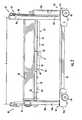
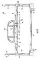
FIG. 1 is a perspective view of a patient support apparatus according to a first embodiment of the present invention;FIG. 2 is a side, elevational view of the patient support apparatus ofFIG. 1 ;FIG. 3 is a perspective view of the patient support apparatus ofFIG. 1 illustrated with the side rails and a sleep surface removed and showing a patient support deck pivoted to a raised orientation;FIG. 4 is a side, elevational view of the patient support apparatus ofFIG. 3 ;FIG. 5 is a perspective view of a horizontal foot beam and its connection to a pair of foot end elevation assemblies;FIG. 6 is a perspective view of a motor, a vertical shaft, and a collar of one of the elevation assemblies;FIG. 7 is a perspective view of the patient support apparatus ofFIG. 1 illustrating a pivoting feature and an extendable feature of the side rails;FIG. 8 is a perspective view of the patient support apparatus ofFIG. 1 illustrating a support deck extender that increases the length of the support deck;FIG. 9 is a perspective view of the patient support apparatus ofFIG. 1 illustrating the side rails moved to a lowered position;FIG. 10 is a perspective view of the patient support apparatus ofFIG. 1 illustrating the side rails moved to a raised position;FIG. 11 is a perspective view of the patient support apparatus ofFIG. 1 illustrating the side rails moved to an alternative stowed position;FIG. 12 is a side, elevational view of the patient support apparatus ofFIG. 1 illustrating three side rails attached in the upright position;FIG. 13 is a side, elevational view of the patient support apparatus ofFIG. 1 illustrating two side rails in the upright position and one in the stowed position;FIG. 14 is a perspective view of a patient support apparatus according to a second embodiment of the present invention;FIG. 15 is a side, elevational view of the patient support apparatus ofFIG. 14 illustrating the support deck moved to a raised position;FIG. 16 is a side, elevational view of the patient support apparatus ofFIG. 14 illustrating the support deck moved to a lowered position;FIG. 17 is a side, elevational view of the patient support apparatus ofFIG. 14 illustrating the support deck in a pivoted orientation;FIG. 18 is a plan view of the patient support apparatus ofFIG. 14 illustrating the support deck in an extended width configuration;FIG. 19 is a plan view of the patient support apparatus ofFIG. 14 illustrating the support deck in an non-extended width configuration;FIG. 20 is a partial, side, elevational view of an extendable sleep surface shown in a folded configuration that may be used on the patient support apparatuses of eitherFIGS. 1 or14 ;FIG. 21 is a partial, side, elevational view of the extendable sleep surface ofFIG. 20 shown in an unfolded configuration;FIG. 22 is a plan view of the sleep surface ofFIG. 20 shown in a folded configuration;FIG. 23 is a plan view of the sleep surface ofFIG. 22 shown in an unfolded configuration;FIG. 24 is a perspective view of the patient support apparatus ofFIG. 14 shown with an overhead support structure attached;FIG. 25 is a side, elevational view of the patient support apparatus ofFIG. 24 ;FIG. 26 is a perspective view of a patient support apparatus according to a third embodiment of the present invention in which an overhead support structure supporting a patient sleeve is attached;FIGS. 27a-e are front, elevational views of the patient support apparatus ofFIG. 26 showing a sequence of movements of the patient support apparatus and patient sleeve that enables the patient to be turned from a face-up orientation to a face-down orientation, or vice versa;FIG. 28 is a perspective view of a set of side rails that may be used with any of the various patient support apparatus embodiments described herein, as well as other patient support apparatuses;FIG. 29 is a front, elevational view of a side rail that may be used with any of the various patient support apparatus embodiments described herein, as well as other patient support apparatuses;FIG. 30 is a perspective view of an inductive power station that may be used to wirelessly provide electrical power to any of the patient support apparatus embodiments described herein, as well as other patient support apparatuses;FIG. 31 is perspective view of an alternative inductive power station that may be used to wirelessly provide electrical power to any of the patient support apparatus embodiments described herein, as well as other patient support apparatuses;FIGS. 32a-c are sectional views of a head end rail taken along the line XXXII-XXXII ofFIG. 4 illustrating alternative constructions of the head end rail;FIG. 33 is a perspective view of the patient support apparatus ofFIG. 14 shown with a patient assist assembly attached to the overhead support structure;FIG. 34 is a perspective view similar toFIG. 33 illustrating a patient grip of the patient assist assembly moved to a central region;FIG. 35 is a perspective view similar toFIG. 34 illustrating an overhead beam of the patient assist assembly rotated;FIG. 36 is a perspective view similar toFIG. 35 illustrating the overhead beam supported on one end by a vertical support;FIG. 37 is a perspective view similar toFIG. 36 illustrating the patient grip of the patient assist assembly moved toward the vertical support- The present invention will now be described with reference to the accompanying drawings wherein the reference numerals appearing in the following written description correspond to like-numbered elements in the several drawings. A
patient support apparatus 30 according to one aspect of the present invention is illustrated inFIG. 1 .Patient support apparatus 30 includes abase 32, fourelevation assemblies 34a-d, apatient support deck 36, asleep surface 38, aheadboard 40 positioned at ahead end 42 ofpatient support apparatus 30, and afootboard 44 positioned at a foot end ofpatient support apparatus 30.Base 32 includes a plurality ofwheels 48 and has ahead end 50 and afoot end 52, both of which are oriented in the same direction ashead end 42 andfoot end 46, respectively, ofpatient support apparatus 30.Base 32 further includes fourcorners 54a-d, each of which supports one of theelevation assemblies 34a-d. The fourelevation assemblies 34a-d are adapted to raise and lowerpatient support deck 36 to different heights with respect tobase 32. The detailed construction of the elevation assemblies will be described below with reference toFIGS. 5 &6 . - As is more clearly illustrated in
FIGS. 2-4 ,patient support deck 36 is divided into a plurality of sections, including ahead section 56, aseat section 58, and afoot section 60. Each section may include a plate (not shown) or other flat structure positioned on top of it that helps support a mattress or other type of sleep surface on which a patient lies.Head section 56 is configured to support the head and torso region of a patient lying onsupport deck 36.Seat section 58 is configured to support the buttocks region of a patient lying onsupport deck 36. Andfoot section 60 is configured to support the foot and lower leg region (e.g. the region of the leg below the knee) of a patient lying onsupport deck 36. It will be understood, however, that the precise line of demarcation between thevarious deck sections patient support deck 36 can be varied to include a lesser or greater number of deck sections than the three illustrated inFIGS. 2-4 . - As can be seen more clearly in
FIGS. 3 and4 ,patient support deck 36 is supported by way of a pair of head end rails 62 and a pair of foot end rails 64. Eachhead end rail 62 extends fromhead end 42 ofpatient support apparatus 30 to anintermediate location 66 located betweenhead end 42 andfoot end 46 ofpatient support apparatus 30. Eachfoot end rail 64 extends fromfoot end 46 ofpatient support apparatus 30 tointermediate location 66. Head end rails 62 and foot end rails 64 are pivotably coupled to each other atintermediate location 66 by way of one or more pivot pins 68 (FIG. 4 ). - In the embodiment illustrated in
FIGS. 3 and4 , eachfoot end rail 64 is constructed of a rigid, non-extensible beam, while eachhead end rail 62 is comprised of abeam 70 and asleeve 72. (Foot end rail 64 could also, or alternatively, be constructed of a beam and sleeve like that ofbeam 70 andsleeve 72, if desired).Beam 70 andsleeve 72 each extend in longitudinal directions that are parallel to each other.Beam 70 is slideably received withinsleeve 72 such thatbeam 70 can retract into or extend out ofsleeve 72, thereby altering the overall length ofhead end rail 62.Beam 70 may include abent region 71, such as is shown inFIG. 2 , or it may be completely straight, such as is shown inFIGS. 12 and13 . In addition to the varying shapes ofbeam 70, the manner in whichsleeve 72 interacts withbeam 70 can be varied widely within the scope of the present invention.FIGS. 32a-c , which are cross sections of one of the head end rails 62 ofFIG. 4 , illustrate three different possible configurations ofbeam 70 andsleeve 72, although additional configurations can also be used. - In
FIG. 32a ,beam 70 is completely enveloped bysleeve 72 and no mechanical structures are positioned between the outside perimeter ofbeam 70 and the inside perimeter of sleeve 72 (the distance between these two perimeters is exaggerated for clarity inFIG. 32a ). A suitable lubricant may be optionally be inserted into aspace 74 defined between the exterior ofbeam 70 and the interior ofsleeve 72 to facilitate the sliding ofbeam 70 with respect tosleeve 72. - In an alternative arrangement illustrated in
FIG. 32b , one ofbeam 70 andsleeve 72 can include a plurality of raisedbearings 76 inspace 74 that provide limited contact betweenbeam 70 andsleeve 72 to thereby facilitate sliding ofbeam 70 with respect tosleeve 72. WhileFIG. 32b illustratessleeve 72 as including the raisedbearings 76, the raised bearings could alternatively be attached tobeam 70. Further, the location, number, and shape of the raisedbearing 76 can be varied from that depicted inFIG. 32c . - In another alternative arrangement depicted in
FIG. 32c , a plurality ofrollers 78 are sandwiched betweenbeam 70 andsleeve 72 inspace 74.Rollers 78 may be spherical rollers, cylindrical rollers, or other types of rollers.Rollers 78 may be held in place by one or more bearing races 80. The number and location ofrollers 78, as well as the number, location, and configuration of bearingraces 80, can be varied from that depicted inFIG. 32c . - In addition to the configurations illustrated in
FIGS. 32a-c ,beam 70 andsleeve 72 can be moveably coupled to each other in still other manners. As one example,sleeve 72 could be constructed to only partiallyenvelope beam 70. As another example, the rectangular cross-sectional shape ofbeam 70 andsleeve 72 could be varied to circular, square, or other shapes. Still other variations ofbeam 70 andsleeve 72 can be implemented. - As was noted above,
head end rail 62 is pivotably coupled tofoot end rail 64. More specifically, in the embodiment illustrated inFIGS. 3 and4 ,foot end rail 64 is pivotably coupled tobeam 70 ofhead end rail 62. The pivoting ofhead end rail 62 with respect tofoot end rail 64 is carried out by an actuator 82 (FIGS. 3 and4 ). In accordance with at least one aspect of the present invention,actuator 82 may take on any configuration that enables head end rails 62 and foot end rails 64 to pivot with respect to each other. In accordance with another aspect of the present invention,actuator 82 may be configured in the manner illustrated inFIGS. 3 and4 . - In the embodiment illustrated in
FIGS. 3 and4 ,actuator 82 includes a horizontal threadedshaft 84 to which a first pair ofarms 86a,b and a second pair of arms 88a,b are attached. Horizontal threadedshaft 84 is powered to rotate by amotor 90.First arms 86a and b are each attached at their foot end (i.e. the end closest to foot end 46 of patient support apparatus 30) to one of collars 92a and b, respectively. Second arms 88a and b are each attached at their head end (i.e. the end closest to head end 42 of patient support apparatus 30) to one of collars 92a and b, respectively. Collars 92a and b each include one or more internal threaded apertures that matingly couple to the exterior threads on horizontal threadedshaft 84. Collars 92a and b thereby threadingly matearms 86a,b and 88a,b to horizontal threadedshaft 84. The head ends offirst arms 86a and b are pivotably secured to any suitable locations underneathseat section 58 ofsupport deck 36. The foot ends of second arms 88a and b are pivotably secured to any suitable locations underneathfoot section 60 ofsupport deck 36. - In general,
actuator 82 operates in the same manner as a conventional car jack, which multiplies the torque ofmotor 90 such that an enormous pivoting force can be created betweenseat section 58 andfoot section 60, thereby allowingpatient support apparatus 30 to sustain greater patient loads. More specifically, the operation ofmotor 90 causes threadedshaft 84 to turn in either of two directions. In a first direction, the rotation of threadedshaft 84 causes collars 92a and b to move horizontally toward each other along the axis defined byshaft 84. In the second, opposite direction, the rotation of threadedshaft 84 causes collars 92a and b to move horizontally away from each other along the axis defined byshaft 84. When collars 92a and b move toward each other, the angle defined betweenfirst arm 86a and second arm 88a increases (along with the angle defined betweenfirst arm 86b andsecond arm 88b), causing the distance between the head ends offirst arms 86a and b and the foot ends of second arms 88a and b to increase, thereby urgingseat section 58 andfoot section 60 toward the horizontal orientation. In contrast, when collars 92 and b move away from each other, the angle defined betweenfirst arm 86a and second arm 88a decreases (along with the angle defined betweenfirst arm 86b andsecond arm 88b), causing the distance between the head ends of first arms 86 and b and the foot ends of second arms 88a and b to decrease, thereby urgingseat section 58 andfoot section 60 to pivot with respect to each other (more specifically, the foot end ofseat section 58 and the head end offoot section 60 pivot upwardly). - When actuator 82 changes the orientation of
deck sections sleeve 72 andbeam 70 will slide with respect to each other. This sliding will either increase or decrease the overall length ofhead end rail 62. However, the overall distance A (FIG. 4 ) between the posts 96 athead end 42 and the posts 96 atfoot end 46 remains the same as it was whendeck sections FIG. 2 ). The extension and retraction ofbeam 70 andsleeve 72 thereby allowspatient support deck 36 to be completely supported byelevation assemblies 34a-d that are positioned at fixed locations onbase 32, even whensupport deck 36 pivots to orientations other than horizontally flat. - When
deck sections actuator 82, a distance B (FIG. 4 ) betweenhead section 56 andseat section 58 also changes. More specifically, as the pivotal junction betweenseat section 58 andfoot section 60 moves upwardly from the horizontal orientation (FIG. 2 ) to a raised orientation (such asFIG. 4 ), distance B increases. Further, as the pivotal junction betweenseat section 58 andfoot section 60 moves downwardly to the horizontal orientation, distance B decreases. The changing length of distance B operates as a shear reduction mechanism that reduces the shear forces that would otherwise be created between thesleep surface 38 and the patient as thesupport deck 36 pivots. The pivoting ofhead section 56 between the horizontal orientation illustrated inFIG. 2 to a raised orientation, such as that shown inFIG. 4 , is carried out by way of a separate actuator (not shown) that is suitably coupled betweenhead section 56 and head end support rails 62 (or structures attached thereto). This actuator can be activated independently ofactuator 82, or simultaneously therewith. FIGS. 5 and6 illustrate in greater detail the construction of two of theelevation assemblies 34c & d. As illustrated inFIG. 6 ,elevation assembly 34c includes a vertical threadedshaft 94c housed with a cylindrical post 96 that extends vertically upward fromcorner 54c ofbase 32. Vertical threadedshaft 94c has threads on its exterior surface that mate with interior threads on acollar 98c.Collar 98c is pivotably joined to one end of a head endhorizontal beam 100. The other end of head endhorizontal beam 100 is joined to collar 98d, which is threadingly mounted onto a vertical shaft 94d (not shown) insideelevation assembly 34d. Housed withinbase 32 at each ofcorners 54a-d is amotor 102. Eachmotor 102 is coupled with one of the threaded shafts 94a-d in each of theelevation assemblies 34a-d. Operation ofmotors 102 causes their respective vertical threaded shafts 94a-d to rotate. This rotation, in turn, causes collars 98a-d to move upward or downward, depending upon the direction of rotation of threaded vertical shafts 94a-d. Whencollars 98c-d move upward or downward, they likewise cause head endhorizontal beam 100 to move upward or downward. Similarly, when collars 98a-b move upward or downward, they likewise cause a foot endhorizontal beam 104 to move upward or downward (FIG. 1 ).- The upward or downward movement of head end
horizontal beam 100 causes an upward or downward movement of the head end of patient support deck 36 (i.e. the end ofsupport deck 36 adjacent head end 42 of patient support apparatus 30). The upward or downward movement of foot endhorizontal beam 104 causes an upward or downward movement of the foot end ofpatient support deck 36. Because head end rails 62 are each pivotably coupled by any suitable means (such as, but not limited to, a ball joint) to head endhorizontal beam 100, and because foot end rails 64 are also each pivotably coupled by any suitable means (such as, but not limited to, a ball joint) to foot endhorizontal beam 104, it is possible to raise head endhorizontal beam 100 and foot endhorizontal beam 104 to different heights. This causespatient support deck 36 to tilt in a longitudinal direction. By independently controlling the height of head endhorizontal beam 100 and foot endhorizontal beam 104,patient support deck 36 can be tilted to the Trendelenberg and reverse Trendelenberg positions, as well as other positions. - A controller (not shown) may be provided at any suitable location on
patient support apparatus 30 that controls the speed of operation of each of themotors 102. The controller may include a conventional microprocessor or microcontroller, or any other suitable electronic control circuitry for controlling the speed of themotors 102 in theelevation assemblies 34a-d. The controller may desirably be part of a closed loop control circuit, although open loop control circuits may also be used. In one embodiment, the controller may be a proportional-integral-derivative (PID) controller. The controller is configured to operate the four motors 102a-d in several different manners. In a first manner, the controller operates each of the four motors 102a-d at the same speed, causingsupport deck 36 to rise or fall uniformly. In a second manner, the controller operates the motors ofelevation assemblies 34a & b at the same speed, causing the foot end ofsupport deck 36 to rise or fall. In a third manner, the controller operates the motors ofelevation assemblies 34c & d at the same speed, causing the head end ofsupport deck 36 to rise or fall. In a fourth manner, the controller operates the motors ofelevation assemblies patient support deck 36 to tilt about its longitudinal axis (which is made possible by the ball joints, or similar joints, between the collars 98 and eitherbottom bar 108 orbottom bar 118 at the head end and foot ends 42 and 46, respectively, ofpatient support apparatus 30. In a fifth manner, the controller operates the motors ofelevation assemblies 34b & d at the same speed, which also causes thepatient support deck 36 to tilt about its longitudinal axis. The various manners of operating the motors can be combined in any manner, and it will be understood that the controller may operate the motors in still different manners. Further, the controller need not offer all these different manners of controlling themotors 102. - As can be seen more clearly in
FIG. 5 , head endhorizontal beam 100 includes atop shaft 106 and abottom bar 108. Head end rails 62 are pivotably coupled directly totop shaft 106. Aflange 110 is provided at each end ofbottom bar 108 that includes a housing (not shown) in which arotational axis 107 oftop shaft 106 is inserted. This housing allowstop shaft 106 to rotate aboutrotational axis 107. Aconventional load cell 112 may be positioned in betweentop shaft 106 andbottom bar 108. Because of the rotational freedom oftop shaft 106 with respect tobottom bar 108, any weight placed uponpatient support deck 36 will causetop shaft 106 to rotate in the direction indicated by arrow 109 (FIG. 5 ) which will, in turn, induce a reaction force ontoload cell 112.Load cell 112 measures this force and converts it into a weight measurement which may then be passed onto the controller onpatient support apparatus 30, or it may be sent to any other suitable location, such as, but not limited to, a site remote from thepatient support apparatus 30, such as a hospital network or a nurses station, or other location. - Each
flange 110 ofbottom bar 108 is coupled to one ofcollars 98c & d. As was mentioned previously, this coupling may be by any suitable means, such as, but not limited to, ball joints. Other types of joints may also be used. Whatever the selected coupling, space is provided for the coupling by way of a vertical slot 114 (FIG. 6 ) defined along the interior of each of posts 96.Vertical slots 114 provide clearance for the coupling between collars 98 andflanges 110 ofbottom bar 108 as head endhorizontal beam 100 is raised and lowered. - The manner in which foot end
horizontal beam 104 is coupled to collars 98a & b is identical to the manner described above with respect to head endhorizontal beam 100 andcollars 98c & d. Further, foot endhorizontal beam 104 is constructed in a similar manner to that of head endhorizontal beam 100. More specifically, foot endhorizontal beam 104 includes atop shaft 116, abottom bar 118, and aload cell 112 sandwiched betweentop shaft 116 and bottom bar 118 (FIG. 1 ). Theload cell 112 of foot endhorizontal beam 104 measures the weight onpatient support deck 36 that is exerted on the foot end ofpatient support deck 36. Between the twoload cells 112 of head end and foot endhorizontal beams patient support deck 36. The outputs of bothload cells 112 may be transmitted to the controller on the bed, or may be sent off the bed to any other suitable location. Because of the design ofpatient support apparatus 30, it is only necessary to utilize twoload cells 112 to determine the weight of the patient. In contrast, many beds and stretchers of the prior art have utilized three or more load cells to determine a patient's weight. The design ofpatient support apparatus 30 thus reduces the cost and complexity of the patient weight determination feature. - A variety of different types and styles of side rails can be attached to
patient support apparatus 30. Several examples of the different types and configurations of the side rails can be seen inFIGS. 1 ,7 ,9-14 , and28-29 .FIG. 7 illustrates one possible manner of attaching one or more generally planar side rails 120 topatient support apparatus 30. In the manner illustrated inFIG. 7 , eachside rail 120 includes ahorizontal pivot beam 122. Thehorizontal pivot beam 122 of a headend side rail 120a is pivotably coupled to aside beam 124 ofhead section 56.Horizontal pivot beam 122 is thus free to pivot about avertical pivot axis 126 between two orientations. In a first orientation, the general vertical plane defined by headend side rail 120a is oriented parallel to the longitudinal extent ofpatient support apparatus 30. In a second orientation, the general vertical plane defined by headend side rail 120a is oriented perpendicular to the longitudinal extent ofpatient support apparatus 30. The first orientation represents the "in-use" position in which theside rail 120 abuts against the side of thepatient support deck 36. The second orientation represents the "out-of-the-way" position in which theside rail 120 has been pivoted away from thesupport deck 36 in order to allow access topatient support deck 36, such as for transferring the patient to or frompatient support apparatus 30, or for other means. - Foot
end side rail 120b (FIG. 7 ) operates in a similar manner to that described above with respect to headend side rail 120a. That is, footend side rail 120b includes ahorizontal pivot beam 122 that is pivotably attached to one of foot end rails 64. Thehorizontal pivot beam 122 of footend side rail 120b pivots about anothervertical pivot axis 126 located generally near thefoot end 46 ofpatient support apparatus 30. Footend side rail 120b is likewise pivotable between two orientations: one in which it abuts against the edge ofsupport deck 36, and another in which it is swung outwardly frompatient support deck 36 to allow greater access to supportdeck 36. In tandem, headend side rail 120a and footend side rail 120b can be swung open in a manner similar to the saloon doors commonly seen in Western movies. This type of swinging movement allows the side rails 120a and b to be moved completely out of the way, thereby providing greater access topatient support deck 36. While not illustrated inFIG. 7 ,additional side rails 120 may also be provided on the opposite side ofsupport deck 36. Theseadditional side rails 120 may be constructed in the same manner as head and footend side rails 120a & b. Alternatively, the side rails on the opposite side may be constructed to pivot and/or move in different manners. - In addition to the pivoting about
pivot axis 126,side rails 120a & b may further be pivotable about a horizontal pivot axis defined by pins 128 (FIG. 7 ).Pins 128 are defined at the intersection of avertical member 130 and ahorizontal member 132 of side rails 120.Pins 128 enableside rails 120 to pivot between the upright orientation depicted inFIG. 7 and a lowered orientation (not shown) in which anedge 134 has moved from being positioned on the top ofside rail 120 to being positioned on the bottom ofside rail 120. In other words, side rails 120 swing about the pivot axis ofpins 128 such that the planar body ofside rails 120 moves to an elevation generally lower than that ofsleep surface 38, yet still in the same plane as that illustrated inFIG. 7 . - Side rails 120 may further be horizontally adjustable. Specifically,
horizontal members 132 may be slideably attached to the underside of horizontal pivot beams 122 such thatvertical members 130 can be moved further away from, or closer to, horizontal pivot beams 122. This enables the distance betweenside rails 120 positioned on opposite sides ofsupport deck 36 to be adjusted. Thus, if extra space is needed onsupport deck 36 to accommodate a larger patient, or for other reasons, side rails 120 can be slid away fromsupport deck 36 to create this extra space. The manner in whichhorizontal members 132 may be slidingly coupled tohorizontal pivot beam 122 can be varied within the scope of the present invention. Such a coupling may include, but is not limited to, a sleeve-and-beam type of construction the same as, or similar to, any of the various configurations ofbeam 70 and sleeve 72 (including those constructions ofFIGS. 32a-c ). - In an alternative arrangement,
horizontal members 132 may be pivotably coupled to the underside ofpatient support deck 36 at their interior ends 136 (FIG. 7 ). This would enable the side rails 120 to pivot between the orientation depicted inFIG. 7 and that shown inFIG. 9 . As can be seen inFIG. 9 , side rails 120 have been pivoted to a lowered position suitable for transferring a patient to or fromsleep surface 38. Such a pivoting takes place about a horizontal pivot axis (not shown) that extends in the direction of the longitudinal axis of the patient support apparatus 30 (i.e. in the direction fromhead end 42 to footend 46, or vice versa). - In an alternative method of attachment, side rails 120 can be coupled to support
deck 36 such that they are pivotable to a flat, horizontal orientation that then allows the side rail to be slid underneathpatient support deck 36.FIG. 11 illustrates an example of this type of attachment to supportdeck 36. As shown,patient support apparatus 30 includes twoside rails 120 that are in the upright position, and twoside rails 120 that have been pivoted and slid to the stowed position underneathsupport deck 36. This stowed position offers the advantages of moving the side rail completely out of the way of the patient, and also consuming very little space betweensupport deck 36 andbase 32. This latter advantage ensures thatsupport deck 36 will still be able to be lowered to a very small height above the floor. - When side rails 120 are attached and pivotable in the manner illustrated in
FIG. 11 , it should be noted that the side rails 120 do not interfere with the lowering ofsupport deck 36. Stated alternatively, when the side rails 120 are in the stowed position andsupport deck 36 is lowered to its lowest orientation, the stowedside rails 120 will not contact either one of a pair of base beams 33. Base beams 33 are part ofbase 32 and they extend longitudinally fromhead end 42 to foot end 46 ofpatient support apparatus 30. Because base beams 33 are positioned generally along the longitudinal center ofpatient support apparatus 30, the side rails 120, when in the stowed position, will not contact base beams 33, but will instead fit into one ofspaces 35 adjacent base beams 33. Thus, side rails 120 do not create a physical limitation on the degree to whichsupport deck 36 may be lowered. FIGS. 28 and29 illustrate alternative embodiments of side rails that may be attached topatient support apparatus 30. InFIG. 28 , the side rails 320 are divided into two sections: astationary section 322 and apivotable section 324.Pivotable sections 324 are pivotable about vertical pivot axes 326. When attached to supportdeck 36 in the configuration illustrated inFIG. 28 , thepivotable sections 324 of adjacent side rails 320 are next to each other. Whenpivotable sections 324 are both opened (i.e. pivoted to the orientation shown inFIG. 28 ), anaccess space 328 is created betweenside rails 320 that provides ample room for patient ingress and egress ontopatient support apparatus 30. Further,pivotable sections 324 can be used as handles which the patient may grip to help support himself or herself as he or she exits or enterspatient support apparatus 30.- In another alternative, a side rail 330 (
FIG. 29 ) may be incorporated into any of the patient support apparatuses described herein.Side rail 330 includes apivot point 332 that enables theside rail 330 to be pivoted between a raisedorientation 334 and a loweredorientation 336.Side rail 330, as well as any of the other side rails discussed herein, may include acontrol panel 338 with one or more user-activated controls that enable either the patient or attending personnel to control various features ofpatient support apparatus 30. The features that may be controlled bycontrol panel 338 include the raising and lowering ofpatient support deck 36, the pivoting of the various sections ofpatient support deck 36, the reading ofload cells 112, communications with health care personnel at remote locations (e.g. remote nurse call), and any other functions that may be desirably performed bypatient support apparatus 30. - While not illustrated in the drawings, any of the side rails 120, 320, and 330 may include suitable means for securing the side rails in the different orientations to which they are pivotable. Such means may include detents, latches, or other structures that allow the side rails to be releasably held in any desirable orientation. Further, the sliding of
horizontal members 132 along the underside of horizontal pivot beams 122 may include structures for securinghorizontal members 132 at selected locations along pivot beams 122. Any conventional structures may be used for this securing. Thus, any of the side rails discussed herein can be locked in any of the various orientations to which they are pivotable or otherwise moveable. FIG. 8 depicts asupport deck extender 138 that may be attached to thefoot end 46 ofpatient support deck 36.Support deck extender 138 includes twoside beams 140 and anend beam 142 attached to each of the side beams 140 at a right angle.Foot board 44 is attached to endbeam 142.Support deck extender 138 is slideably attached tofoot section 60 ofsupport deck 36 such thatextender 138 can slide in the directions indicated bydouble arrow 144. That is,extender 138 can slide towardfoot section 60 or away from it. When slid away fromfoot section 60,extender 138 effectively increases the length of patient support deck 36 (FIG. 10 illustratesextender 138 slid partially away from support deck 36). This may be useful for taller patients, or in other situations when a longerpatient support deck 36 is desirable.Extender 138 may be slidingly coupled tofoot section 60 in any suitable manner. In one manner,extender 138 is slidingly coupled to the underside offoot section 60 in a beam-and-sleeve type arrangement that may take on any of the various configurations discussed above regardingbeam 70 and sleeve 72 (including the illustrations ofFIGS. 32a-c ).Extender 138 may be coupled in still other manners to footsection 60.FIG. 10 illustratespatient support apparatus 30 with twoside rails 120 positioned on either side ofhead section 56 ofsupport deck 36.FIG. 10 also illustrates twoside rails 120 positioned on either side ofseat section 58 ofsupport deck 36. WhileFIG. 10 does not illustrate anyside rails 120 positioned on the sides offoot section 60 ofsupport deck 36,patient support apparatus 30 may includes side rails attached tofoot section 60. Such a situation is depicted inFIGS. 12 and13 , which illustrate threeside rails 120 on each side ofsupport deck 36, for a total of six side rails 120. Each of the sixside rails 120 could be replaced by any one ofside rails FIGS. 12 and13 could be attached to supportdeck 36 such that they pivot in any of the manners discussed above with respect toside rails 120 and/orside rails FIG. 13 , the side rails 120 are pivotable and slideable to a stowed position underneathsupport deck 36 in which the general plane of the side rail is in a horizontal orientation.- Whatever type of side rails that are used with
patient support apparatus 30, they may desirably be height adjustable such that atop edge 146 is positioned at least nine inches above atop face 148 ofsleep surface 38.FIG. 10 illustrates this nine inch height abovetop face 148 ofsleep surface 38. Further, the side rails 120 (or 320 or 330) adjacent head end 42 ofpatient support apparatus 30 are preferably dimensioned such that afront side edge 149 of side rails 120 is no greater than 2.5 inches away from the adjacent post 96. This ensures that the horizontal gap between thefront side edge 149 and the post 96 is no greater than 2.5 inches, which helps ensure that a patient's arms or legs do not become wedged between one of the side rails 120 and posts 96. If any side rails 120 (or 320 or 330) are attached tofoot section 60 ofsupport deck 36, such side rails may also desirably be dimensioned such that the horizontal gap between their foot side edges 150 andposts 96a & b is no greater than 2.5 inches. Base 32 ofpatient support apparatus 30 may be configured to include one or more recesses in atop surface 152 of each ofbase corners 54a-d (FIG. 1 ). Such recesses may be dimensioned to support various hospital equipment, such as IV poles, an oxygen canister 154 (FIG. 1 ), medical devices, or any other structure that may desirably be attached topatient support apparatus 30. Alternatively or additionally,headboard 40 and/orfootboard 44 may include coupling structures for supporting oxygen canisters 154 (FIGS. 12 &13 ), IV poles, other hospital equipment or medical devices.Base 32 may further include a fifth wheel (not shown) positioned in the center region ofbase 32 that can move between a lowered position in which it is in contact with the floor and a raised position in which it is out of contact with the floor. Such a fifth wheel can assist in steeringpatient support apparatus 30 as it is pushed onwheels 48 from location to location. Such a fifth wheel can be especially useful when all ofwheels 48 are castered.FIGS. 14-19 and24-25 illustrate an alternative embodiment of apatient support apparatus 230.Patient support apparatus 230 shares many features and components in common withpatient support apparatus 30. Those components ofsupport apparatus 230 that are the same as those ofsupport apparatus 30 are labeled with the same reference numerals and operate in the same manner as described previously. For example,patient support apparatus 230 includes fourposts 96a-d which house fourelevation assemblies 34a-d. Each of theseelevation assemblies 34a-d works in the same manner as was previously described above with respect to supportapparatus 30. That is, they each include a motor 102 (not shown inFIGS. 14-19 and24-25 ) that rotates a vertical shaft 94 (also not shown) that, depending upon the direction of rotation, will raise or lowerpatient support deck 36.FIGS. 14 and16 illustratepatient support deck 36 in the lowest orientation, whileFIG. 15 illustratespatient support deck 36 in its highest orientation. A controller, such as the one described above with respect to supportapparatus 30, may be included at any suitable location to control the operation of each of the motors inelevation assemblies 34a-d in the same manners described above with respect to supportapparatus 30.- The
support deck 36 ofpatient support apparatus 230 is also pivotable from the flat orientation ofFIG. 14 into different orientations, one of which is illustrated inFIG. 17 . These pivotable positions are achieved by way of an actuator 156 (FIGS. 15 &17 ), which may be constructed in the same manner asactuator 82 described above, or in any alternative manner. Asactuator 82 pivots the sections ofsupport deck 36 to different orientations,sleeve 72 andbeam 70 of head end rails 62 will retract into and extend out of each other in the manner described above. With the exception of those details ofpatient support apparatus 230 explicitly mentioned below, all elements ofpatient support apparatus 230 bearing the same reference numerals as those ofpatient support apparatus 30 perform the same function and operate in the same manner as described above with respect to supportapparatus 30. Accordingly, no further discussion of the common elements will be necessary. Headboard 40 andfootboard 44 may both be slidingly engaged to the two posts 96 nearest them. Operation of elevation assemblies 34 simultaneously raises and lowersheadboard 40 andfootboard 44, which each slide within vertical tracks 238 (FIG. 14 ) defined in the interior sides of posts 96.- As can be seen in
FIGS. 18 and19 ,support deck 36 ofpatient support apparatus 230 includes a plurality ofwidth extenders 232 that slide toward and away from the center longitudinal line ofsupport apparatus 230 in the directions indicated bydouble arrow 234.Width extenders 232 allow the width ofpatient support deck 36 to be adjusted in order to accommodate patients of different sizes, as well as for any other reason it may be desirable to adjust the width ofpatient support deck 36.FIG. 18 illustrateswidth extenders 232 in the extended position whileFIG. 19 illustrates thewidth extenders 232 in the retracted position.Width extenders 232 may retract underneath the respective deck section (56, 58, or 60) to which it is coupled, ordeck sections extenders 232 to be slid directly intosections deck sections Extenders 232 each include a plurality ofcross beams 236 that are received within respective sleeves positioned either within or underneathdeck sections beams 236 may take on any suitable configuration, including such configurations as those discussed above with respect tobeam 70 and sleeve 72 (including the variations ofFIGS. 32a-c ). FIGS. 20-23 illustrate one embodiment of anextendable sleep surface 38 that can be used withpatient support apparatus 230 whenextenders 232 are utilized.FIGS. 20-23 illustrate anextendable sleep surface 240 having atop face 148, abottom face 158, a pair of side edges 160, and astrip region 162 adjacent eachside edge 160.Strip region 162 contains afold line 164 that can fold about apivot region 166 between a folded orientation (FIG. 20 ) and an unfolded orientation (FIG. 21 ). Both sides ofsleep surface 38 may include astrip region 162 that is foldable between the folded and unfolded orientations, or only a single side ofsleep surface 230 may include astrip region 162 that is foldable. As can be seen inFIG. 22 , which is a plan view ofsleep surface 240 in the folded orientation,sleep surface 240 has afirst width 168. As can be seen inFIG. 23 , which is a plan view of sleep surface in the unfolded orientation,sleep surface 240 has asecond width 170 when unfolded that is greater thanfirst width 168 when folded. Asingle sleep surface 240 can thus be used withpatient support apparatus 230 and the width of thesleep surface 240 can be adjusted to correspond to the width adjustments made to supportdeck 36 viawidth extender 232.Strip region 162 may also included astiff region 170 that is stiffer than the surrounding regions, particularly those regions neartop face 148 which are desirably soft so that a patient can lie comfortably onsleep surface 240.Stiff region 170, however, is relatively more rigid than these regions such that whenextendable sleep surface 240 is unfolded to the orientation ofFIG. 21 ,stiff region 170 becomes positioned alongside edge 160. The relative stiffness ofstiff region 170 helps support theouter edges 160 ofsleep surface 240 against downward pressures applied totop face 148 over the areas above agap 172 left behind by the unfolding offold line 164. Thus, while no material ofsleep surface 240 is contained withingap 172,stiff region 162 helps provide a certain amount of flexible resistance to the area oftop face 148 abovegap 172, thereby ensuring the patient still experiences a certain degree of softness in this region.Extendable sleep surface 240, as withsleep surface 38, may be made out of any suitable materials that provide suitable softness and comfort for a patient positioned on top ofsupport deck 36. In one embodiment, either or both of sleep surfaces 38 and 240 may include one or more air bladders that are selectively inflatable to different levels of pressure, thereby allowing different levels of support to be provided to the patient. If more than one air bladder is provided, the air bladders may be selectively inflatable so that different ones of the air bladders can be inflated to different pressures.FIGS. 24 and25 illustratepatient support apparatus 230 with an optionaloverhead support structure 180 attached to the tops of each ofposts 96a-d.Overhead support structure 180 includes fourvertical beams 182a-d, a pair oflongitudinal beams 184a & b, and a plurality ofcross beams 186 interconnecting thelongitudinal beams 184a & b.Overhead support structure 180 may be used to support a variety of different items, such as a privacy canopy that partially or wholly envelopespatient support apparatus 230 for purposes of giving the patient some privacy.Overhead support structure 180 may also be used to support an electronic display, such as a television, monitor, or screen, on which entertainment (such as television channels) may be displayed, or through which the Internet may be accessed, or through which video teleconferencing with remotely located medical personnel may take place. A camera may also optionally be positioned onoverhead support structure 180 to allow video monitoring of the patient, or for video teleconferencing. Still further,overhead support structure 180 may be used to support or hold various medical equipment.- In one embodiment, illustrated in
FIGS. 26 and27a-e ,overhead support structure 180 supports a patientproning apparatus 188.Patient proning apparatus 188 may be coupled together with eitherpatient support apparatus 30 orpatient support apparatus 230.Patient proning apparatus 188 includes apatient sleeve 190 that wraps under and around a patient in the manner illustrated more clearly inFIG. 26 .Patient sleeve 190 is supported by an overhead beam 192 (FIG. 26 ), which may be hung from any of longitudinal beams 184 or crossbeams 186 ofoverhead support structure 180. The manner in whichpatient proning apparatus 188 assists in the turning over of a patient is illustrated in greater detail inFIGS. 27a-e , which illustrate the motion of patientproning apparatus 188 and apatient 194 at different time intervals during the proning process. - At an initial time period illustrated in
FIG. 27a ,overhead beam 192 is positioned at aleft side 196 ofpatient 194. At a subsequent time period illustrated inFIG. 27b , the vertical distance betweensleep surface 38 andoverhead beam 192 is increased. This creates a rotating force that urges thepatient 194 toward the orientation depicted inFIG. 27b . The increased vertical separation betweenoverhead beam 192 andsleep surface 38 may be created either by lowering thesupport deck 36 or raisingoverhead beam 192, or a combination of both. As the vertical distance betweensleep surface 38 andoverhead beam 192 is increased,vertical beam 192 is moved rightward in the direction ofarrow 200.FIG. 27c illustratesvertical beam 192 positioned above the longitudinal centerline of the patient support apparatus (which may beapparatus 30 or 230). Untiloverhead beam 192 reaches the longitudinal centerline of the patient support, the vertical distance betweensleep surface 38 andoverhead beam 192 may continue to be increased. Afteroverhead beam 192 has reached the longitudinal centerline of the patient support and continues to move rightward (inFIGS. 27a-e ), the vertical distance betweensleep surface 38 andoverhead beam 192 may begin to be decreased, either by loweringoverhead beams 192, or raisingsupport deck 36, or a combination of both. As illustrated inFIG. 27e , the continued rightward movement ofoverhead beam 192 and the continued decrease in the vertical separation betweenoverhead beam 192 andsleep surface 38 eventually results inpatient 194 being turned onto his or her stomach. Afterpatient 194 has been rotated to the desired orientation,patient sleeve 190 can be disconnected fromoverhead beam 192 and either pulled out from underneathpatient 194, or left thereunder. If left thereunder,sleeve 190 may be tucked into a suitable storage area, such as underneathdeck 36, or elsewhere. - The sideward movement of
overhead beam 192 may be powered by suitable motors positioned at appropriate locations onoverhead support structure 180, or it may be done manually by aperson grabbing sleeve 190 and exerting the proper sideward force. The up and down motion ofoverhead beam 192, if instituted, may also be done by appropriately positioned motors. If the vertical distance betweenpatient support deck 36 andoverhead beam 192 is altered by changing the height ofsupport deck 36, any suitableheight adjustment mechanism 202 may be used.Height adjustment mechanism 202 may include theelevation assemblies 34a-d described earlier, orproning apparatus 188 may be instituted on other patient supports that have different types of elevation adjustment mechanisms. - The actuators included on either of
patient support apparatuses patient support apparatuses base 32 that inductively receives electrical power from an inductive power station 210 (FIGS. 30-31 ).Power station 210 ofFIG. 30 may be positioned on afloor 212 adjacent avertical wall 214.Power station 210 includes acoil 216 through which an alternating current is passed.Coil 216 may be positioned underneath a top surface offloor 212 so as to not be a trip hazard. When it is desirable to receive electrical power frompower station 210, the patient support apparatus (e. g. 30 or 230) is wheeled to a location such that its inductive power receptor is positioned vertically abovecoil 216. The alternative current passed throughcoil 216 creates an electromagnetic wave that induces a voltage on a second coil within the inductive power receptor on the patient support apparatus. This induced voltage drives a current that may be used to power any of the various electrical systems on the patient support apparatus, or to re-charge a battery, or both. - In an alternative inductive power station 210', a
conductive plate 218 is positioned on or underneathfloor 212.Plate 218 is coupled to a source of alternating current such that it radiates an electromagnetic wave that induces a voltage on a coil or plate positioned on the patient support apparatus.Plate 218 orcoil 216 can thus be used to wirelessly transmit power fromstations 210 or 210' to a mobile patient support apparatus, such aspatient support apparatus 30 or 30'. FIGS. 33-37 illustrate apatient assist assembly 246 that may be coupled tooverhead support structure 180 in order to assist a patient during ingress into, or egress out of,patient support apparatus 230. Patient assistassembly 246 includes anoverhead beam 248, asleeve 250, apatient grip 252, and a vertical support 253 (FIGS. 35-37 ) positioned away frompatient support apparatus 230.FIGS. 33-37 generally illustrate the sequence of movements ofpatient assist assembly 246 when used to assist a patient out ofpatient support apparatus 230. When used to assist a patient intopatient support apparatus 230, the sequence of movements would be reversed.- As shown in
FIG. 33 ,patient grip 252 is generally positioned abovefoot section 30 ofpatient support apparatus 30.Patient grip 252 includes one or more handlebars 254 (more clearly shown inFIGS. 35-37 ) which a patient may grasp onto when entering or exitingpatient support apparatus 30.Patient grip 252 is supported byoverhead beam 248 and is also moveable alongoverhead beam 248 in the manner indicated bydouble arrow 256 inFIG. 33 . That is,patient grip 252 is moveable alongoverhead beam 248 in the longitudinal direction ofbeam 248. When a person is to exit frompatient support apparatus 230,grip 252 is moved alongbeam 248 to a position generally abovehead section 56 ofsupport deck 36. The movement ofgrip 252 alongoverhead beam 248 may be powered by any suitable actuator (not shown). - After
grip 252 has been moved to a location abovehead section 56, the patient grasps one or more of thehandlebars 254 and uses the handlebars to pull him or herself upward to the best of their ability. Thereafter, the patient continues to hold onto the handlebars asgrip 252 is moved toward a central region above patient support apparatus 230 (such as shown inFIG. 34 ). Aftergrip 252 has been moved to the central region shown inFIG. 34 ,overhead beam 248 is rotated about a vertical axis 258 (FIG. 35 ). InFIG. 35 , this rotation is illustrated as a rotation of approximately ninety degrees, although it will be understood that the use ofpatient assist assembly 246 can utilize other amounts of rotation. After whatever desirably rotation amount has been achieved,overhead beam 248 moves longitudinally in the direction indicated by arrow 260 (FIG. 36 ) withinsleeve 250. This movement continues untilbeam 248 reachesvertical support 253. Whenvertical beam 248 reachesvertical support 253, it is coupled thereto. Any suitable mechanism may be used to releasablysecure beam 248 tovertical support 253.Vertical support 253 may be positioned on apedestal 262 having one ormore wheels 264 that facilitate movingvertical support 253 to the appropriate location for coupling withvertical beam 248. - After
beam 248 has been coupled tovertical support 253,grip 252 is moved along the length ofbeam 248 in the same direction asarrow 260.FIG. 37 illustratesgrip 252 after it has been moved to a location away frompatient support apparatus 230. Whilegrip 252 moves alongbeam 248, the patient continues to griphandlebars 254. The movement ofgrip 252 as the patient is grippinghandlebars 254 allows the patient to more easily assist in the transfer of him or herself out ofpatient support apparatus 230.Grip 252 thus provides a mobile support for the patient to grasp during ingress and egress that moves with the patient and assists the patient in a better manner than prior methods of assisting the patient. - In either of
patient support apparatuses elevation assemblies 34a-d are positioned outside of a perimeter of support deck 36 (i.e. the perimeter ofsupport deck 36 when viewingsupport deck 36 in a plan view). This ensures that the physical space occupied byelevation assemblies 34a-d does not limit the downward movement ofsupport deck 36, which happens in many prior art patient supports where the elevation assemblies are positioned underneath the support deck and thereby occupy physical space that the support deck might otherwise be lowered into. Stated alternatively, the footprint of deck 36 (i.e. space underneath support deck 36) is generally free of any obstructions other than base 32 (see, e.g.FIG. 2 ).Support deck 36 can thus be lowered all the way down tobase 32. Further, because there is no separate horizontal frame betweensupport deck 36 andbase 32,support deck 36 can be lowered to a lower elevation than would be possible if such a frame were positioned betweensupport deck 36 andbase 32. - While the present invention has been described above with respect to
patient support apparatuses support apparatus 30 can be incorporated intosupport apparatus 230, or vice versa. For example, the supportdeck width extenders 232 ofpatient support apparatus 230 can be incorporated intosupport apparatus 30. Also, theoverhead support structure 180 ofsupport apparatus 230 can be mounted to the posts 96 ofpatient support apparatus 30. Still further, theproning apparatus 188 can be used withpatient support apparatus 30 as well aspatient support apparatus 230. Still other features can be switched and combined from one support apparatus to another. - It will also be understood that a variety of different modifications can be made to various patient support apparatuses described herein. As one example, the number of elevation assemblies 34 can be varied from the four shown in the accompanying drawings. For instance, it would be possible to include only a single elevation assembly at each end of the patient support apparatus. Still further, it would be possible to modify the vertical-threaded-shaft-and-collar construction of elevation assemblies 34 as described previously to incorporate a different design for raising and lowering the
patient support deck 36. Such a modified design might include hydraulics, pneumatics, electrical motors configured with one or more chains, or a variety of other types of mechanisms capable of raising and lowering support deck 3 6. - Additionally, it will be understood that any of the
patient support apparatuses - While the present invention has been described herein in reference to the various embodiments illustrated in the attached drawings, it will be understood by those skilled in the art that the present invention can be modified to include any and all variations that are within the scope of the following claims.
Claims (15)
- A patient support apparatus (30) comprising:a base (32) having a head end (42) and a foot end (46);a support deck (36) adapted to support a patient and having an outer perimeter, said support deck (36) including a foot section (60), a seat section (58), and a head section (56), both said seat section (58) and said foot section (60) pivotable between generally horizontal orientations and raised orientations;a first elevation assembly (34) positioned at the head end (42) of said base (32); anda second elevation assembly (34) positioned at the foot end (46) of said base (32), said first and second elevation assemblies (34) being coupled to said support deck (36) such that said first and second elevation assemblies (34) can raise and lower said support deck (36) with respect to said base (32),wherein said first and second elevation assemblies (34) being positioned outside a footprint of said support deck (36) wherein said footprint is defined by a vertical downward projection of said perimeter onto said base (32);characterized in that said support deck (36) is supported by way of a pair of extensible head end rails (62) and a pair of non-extensible foot end rails (64) pivotally coupled to each other, wherein the extensible head end rails (62) operates as a shear reduction assembly (72, 70) adapted to increase a distance between said head section (56) and said seat section (58) when said foot section (60) and said seat section (58) are pivoted from their respective generally horizontal orientations to their respective raised orientations.
- The patient support apparatus (30) of claim 1 further including an actuator (82) for pivoting said seat section (58), said actuator (82) including:a threaded, horizontal shaft (84) oriented perpendicular to an imaginary line running from said head end (42) of said base (32) to said foot end (46) of said base (32);a first set of arms (86a,b), each of the arms (86a,b) in said first set of arms including a first end threadingly mated to said horizontal shaft (84) and a second end pivotably coupled to an underside of said foot section (60); anda second set of arms (88a,b), each of said arms (88a,b) in said second set of arms (88a,b) including a first end threadingly mated to said horizontal shaft (84) and a second end pivotably coupled to said support deck (36) at a location under said seat section (58).
- The patient support apparatus (30) of claim 1 wherein said first elevation assembly (34) includes:a first vertical threaded shaft (94) and a first threaded collar (98) in engagement with said first vertical threaded shaft (94), said first threaded collar (98) adapted to move vertically upward or downward when said first threaded collar (98) and said first threaded shaft (94) engaged with said first threaded collar (98) rotate with respect to each other;a second vertical threaded shaft (94) and a second threaded collar (98) in engagement with said second vertical threaded shaft (94), said second threaded collar (98) adapted to move vertically upward or downward when said second threaded collar (98) and said second threaded shaft (94) engaged with said second threaded collar (98) rotate with respect to each other; anda head end horizontal beam (100) extending between said first and second threaded collars (98), said head end horizontal beam (100) being pivotably coupled to said support deck (36) adjacent said head section (56).
- The patient support apparatus (30) of claim 3 wherein said second elevation assembly (34) includes:a third vertical threaded shaft (94) and a third threaded collar (98) in engagement with said third vertical threaded shaft (94), said third threaded collar (98) adapted to move vertically upward or downward when said third threaded collar (98) and said third threaded shaft (94) engaged with said third threaded collar (98) rotate with respect to each other;a fourth vertical threaded shaft (94) and a fourth threaded collar (98) in engagement with said fourth vertical threaded shaft (94), said fourth threaded collar (98) adapted to move vertically upward or downward when said fourth threaded collar (98) and said fourth threaded shaft (94) engaged with said fourth threaded collar (98) rotate with respect to each other; anda foot end horizontal beam (104) extending between said third and fourth threaded collar (98), said foot end horizontal beam (104) being pivotably coupled to said foot section (60) of said support deck (36).
- The patient support apparatus (30) of claim 4 further including a first load cell (112) positioned underneath said head end horizontal beam (100) and a second load cell (112) positioned underneath said foot end horizontal beam (104), said first and second load cells (112) providing sufficient force measurements to determine a weight of a patient on said patient support deck (36) without additional force measurements from any load cells (112) other than said first and second load cells (112).
- The patient support apparatus (30) of any preceding claim further including a sleep surface (38) having a foot end, a head end, and a pair of sides, said sleep surface (38) being positioned on top of said support deck (36) and including a strip (162) along at least one of said sides, said strip (162) being foldable between a folded position and an unfolded position, wherein when said strip (162) is in the unfolded position, said sleep surface (38) has a distance between said pair of sides greater than the distance between said pair of sides when said strip (162) is in the folded position.
- The patient support apparatus (30) of any preceding claim further including:a patient sleeve (190) adapted to wrap around a patient while lying on said support deck (36);an overhead support (192) positioned above a patient lying on said patient support apparatus (30), said overhead support (192) adapted to support said patient sleeve (190); andan actuator assembly adapted to increase a vertical distance between said overhead support (192) and said patient support deck (36) while a patient is positioned in said sleeve (190), said actuator assembly further adapted to move said patient sleeve (190) in a horizontal direction perpendicular to an imaginary line extending from said head end (42) to said foot end (46) of said base (32).
- The patient support apparatus (30) of any preceding claim wherein said support deck (36) includes:a first rail (62) extending from said head end (42) of said base (32) to an intermediate location between said foot end (46) and said head end (42) of said base (32), said first rail (62) having a head end pivotably coupled to said first elevation assembly (34); anda second rail (64) extending from said foot end (46) of said base to said intermediate location, said second rail (64) being pivotably coupled to said first rail (62), and said second rail (64) having a foot end (46) pivotably coupled to said second elevation assembly (34);wherein at least one of said first and second rails (62,64) includes a beam (70) and a sleeve (72), said beam (70) and said sleeve (72) each having longitudinal extents that are parallel to each other, said beam (70) and said sleeve (72) adapted to slide with respect to each other such that a length of said at least one of said first and second rails (62,64) can be extended and shortened.
- The patient support apparatus (30) of claim 8 wherein said head section (56) includes a head end (42) and a foot end (46), said head section (56) being pivotably supported by said first rail (62) at a location adjacent said foot end (46) of said head section (56) whereby said head end of said head section (56) is pivotable toward and away from said first rail (62).
- The patient support apparatus (30) of claims 8 or 9 wherein one of said seat section (58) and said head section (56) is mounted to said beam (70) and the other of said seat section (58) and said head section (56) is mounted to said sleeve (72), said seat section (58) and said head section (56) moving away from each other as said first and second rails (62,64) are pivoted away from a flat orientation in which said first and second rails (62,64) are parallel to each other.
- The patient support apparatus (30) of claim 6 wherein said strip (162) includes a stiff portion (170), said stiff portion (170) positioned at an edge of said sleep surface (38) when said strip (162) is unfolded, and said stiff portion (170) positioned along a bottom of said sleep surface (38) when said strip (162) is folded.
- The patient support apparatus (30) of any preceding claim wherein said support deck (36) further includes a length extender (138) movingly coupled to said foot section (60), said length extender (138) movable between a retracted position in which a length of said support deck (36) has a first value, and an extended position in which a length of said support deck (36) has a second value greater than said first value.
- The patient support apparatus (30) of any preceding claim further including a plurality of side rails (120), each of said side rails (120) including an extension (132), said extension (132) being supported by one of said first and second rails (62,64) and movable between an extended position and a retracted position, said side rails (120) being positioned closer to a longitudinal center line of said support deck (36) when in said retracted position than when in said extended position.
- The patient support apparatus (30) of any preceding claim further including a plurality of generally planar side rails (120), each said side rail (120) being pivotably supported by one of said first and second rails (62,64) such that said side rails (120) are pivotable between a first orientation and a second orientation wherein said first orientation is perpendicular to said second orientation.
- The patient support apparatus (30) of any preceding claim further including:a sleep surface (38) positioned on top of said support deck (36);a side rail (120) attached to said support deck (36) along a side of said head section (56);a headboard (40) attached to said support deck (36) at a location adjacent said head section (56), said headboard (40) being oriented generally perpendicular to said side rail (120);a vertical post (96) mounted to said base (32) adjacent said head end (42) of said base (32), said post (96) positioned at corner and extending upwards to a height greater than a maximum height of said sleep surface (38), said maximum height of said sleep surface (38) being defined by a vertical maximum of said first elevation assembly (34).
Applications Claiming Priority (4)
| Application Number | Priority Date | Filing Date | Title |
|---|---|---|---|
| US81752806P | 2006-06-28 | 2006-06-28 | |
| US83039706P | 2006-07-11 | 2006-07-11 | |
| US11/769,959US8056163B2 (en) | 2006-06-28 | 2007-06-28 | Patient support |
| PCT/US2007/072332WO2008003027A2 (en) | 2006-06-28 | 2007-06-28 | Patient support |
Publications (3)
| Publication Number | Publication Date |
|---|---|
| EP2046259A2 EP2046259A2 (en) | 2009-04-15 |
| EP2046259A4 EP2046259A4 (en) | 2012-11-21 |
| EP2046259B1true EP2046259B1 (en) | 2014-07-02 |
Family
ID=38846537
Family Applications (1)
| Application Number | Title | Priority Date | Filing Date |
|---|---|---|---|
| EP07812417.9ANot-in-forceEP2046259B1 (en) | 2006-06-28 | 2007-06-28 | Patient support |
Country Status (3)
| Country | Link |
|---|---|
| US (1) | US8056163B2 (en) |
| EP (1) | EP2046259B1 (en) |
| WO (1) | WO2008003027A2 (en) |
Cited By (1)
| Publication number | Priority date | Publication date | Assignee | Title |
|---|---|---|---|---|
| CN110840689A (en)* | 2019-11-22 | 2020-02-28 | 天津理工大学中环信息学院 | Medical automatic carrying stretcher vehicle and carrying method thereof |
Families Citing this family (100)
| Publication number | Priority date | Publication date | Assignee | Title |
|---|---|---|---|---|
| EP1621174B1 (en)* | 2004-07-30 | 2011-10-19 | Hill-Rom Services, Inc. | Patient support having powered adjustable width |
| US7565708B2 (en) | 2005-02-22 | 2009-07-28 | Jackson Roger P | Patient positioning support structure |
| US9468576B2 (en) | 2005-02-22 | 2016-10-18 | Roger P. Jackson | Patient support apparatus with body slide position digitally coordinated with hinge angle |
| US20150059094A1 (en) | 2005-02-22 | 2015-03-05 | Roger P. Jackson | Patient positioning support structure |
| US9265679B2 (en) | 2005-02-22 | 2016-02-23 | Roger P Jackson | Cantilevered patient positioning support structure |
| US9301897B2 (en) | 2005-02-22 | 2016-04-05 | Roger P. Jackson | Patient positioning support structure |
| US9295433B2 (en) | 2005-02-22 | 2016-03-29 | Roger P. Jackson | Synchronized patient elevation and positioning apparatus for use with patient positioning support systems |
| US8844077B2 (en) | 2005-02-22 | 2014-09-30 | Roger P. Jackson | Syncronized patient elevation and positioning apparatus positioning support systems |
| US9308145B2 (en)* | 2005-02-22 | 2016-04-12 | Roger P. Jackson | Patient positioning support structure |
| US8707484B2 (en)* | 2005-02-22 | 2014-04-29 | Roger P. Jackson | Patient positioning support structure |
| US9744087B2 (en)* | 2005-02-22 | 2017-08-29 | Roger P. Jackson | Patient support apparatus with body slide position digitally coordinated with hinge angle |
| US7739762B2 (en) | 2007-10-22 | 2010-06-22 | Mizuho Orthopedic Systems, Inc. | Surgery table apparatus |
| US9186291B2 (en) | 2005-02-22 | 2015-11-17 | Roger P. Jackson | Patient positioning support structure with trunk translator |
| US10869798B2 (en) | 2006-05-05 | 2020-12-22 | Warsaw Orthopedic, Inc. | Patient positioning support apparatus with virtual pivot-shift pelvic pads, upper body stabilization and fail-safe table attachment mechanism |
| US9642760B2 (en) | 2006-05-05 | 2017-05-09 | Roger P. Jackson | Patient positioning support apparatus with virtual pivot-shift pelvic pads, upper body stabilization and fail-safe table attachment mechanism |
| US9339430B2 (en) | 2006-05-05 | 2016-05-17 | Roger P. Jackson | Patient positioning support apparatus with virtual pivot-shift pelvic pads, upper body stabilization and fail-safe table attachment mechanism |
| US8864205B2 (en)* | 2006-06-28 | 2014-10-21 | Stryker Corporation | Patient support with wireless data and/or energy transfer |
| US7887113B2 (en)* | 2007-07-11 | 2011-02-15 | Stryker Corporation | Powered patient support and fastening system with inductive based power system |
| CZ18426U1 (en)* | 2008-02-15 | 2008-04-07 | Linet, Spol. S R.O. | Bed positioning mechanism |
| US7559102B1 (en)* | 2008-05-14 | 2009-07-14 | Bedlab, Llc | Adjustable bed with sliding subframe for torso section |
| US20090293197A1 (en)* | 2008-05-30 | 2009-12-03 | Joerns Healthcare Inc. | Width adjustment accessory for use with beds |
| GB2474390B (en)* | 2008-07-23 | 2013-02-13 | Engineered Assistance Ltd | Drive mechanism for rotating sleep surface transfer system |
| US20100037397A1 (en)* | 2008-08-14 | 2010-02-18 | RemGenic LLC | Bed |
| EP2470140B1 (en) | 2009-10-02 | 2016-11-23 | Stryker Corporation | Ambulance cot and loading and unloading system |
| US8260475B2 (en)* | 2009-11-19 | 2012-09-04 | Hill-Rom Services, Inc. | Constant low-flow air source control system and method |
| US9301622B2 (en)* | 2009-12-07 | 2016-04-05 | Dreamwell, Ltd. | Shell for mattress for adjustable bed |
| US9101517B2 (en) | 2010-08-30 | 2015-08-11 | Hill-Rom Services, Inc. | Patient-support apparatus with a configurable siderail |
| EP2619724A2 (en) | 2010-09-23 | 2013-07-31 | Stryker Corporation | Video monitoring system |
| US9072646B2 (en) | 2010-12-14 | 2015-07-07 | Allen Medical Systems, Inc. | Lateral surgical platform with rotation |
| CA2853754C (en) | 2011-10-02 | 2020-06-16 | Invacare Corporation | Adjustable bed |
| WO2013058806A1 (en) | 2011-10-17 | 2013-04-25 | Jackson Roger P | Patient positioning support structure |
| US9561145B2 (en) | 2012-02-07 | 2017-02-07 | Roger P. Jackson | Fail-safe release mechanism for use with patient positioning support apparati |
| US9265680B2 (en)* | 2012-03-06 | 2016-02-23 | Operating Room Safety Enterprises, LLC | Surgical table |
| US9474671B2 (en)* | 2012-03-06 | 2016-10-25 | Operating Room Safety Enterprises, LLC | Surgical table |
| US9498397B2 (en) | 2012-04-16 | 2016-11-22 | Allen Medical Systems, Inc. | Dual column surgical support system |
| US8997282B2 (en)* | 2012-05-10 | 2015-04-07 | Hill-Rom Services, Inc. | Bed with a powered width expansion wing |
| US9468307B2 (en) | 2012-09-05 | 2016-10-18 | Stryker Corporation | Inflatable mattress and control methods |
| US9622927B1 (en) | 2012-10-05 | 2017-04-18 | Gf Health Products, Inc. | Bed with extendable and retractable extensions |
| US9173796B2 (en)* | 2013-02-05 | 2015-11-03 | Hill-Rom Services, Inc. | Bed with a powered width expansion wing with manual release |
| US9510981B2 (en) | 2013-03-14 | 2016-12-06 | Stryker Corporation | Reconfigurable transport apparatus |
| US9486373B2 (en) | 2013-03-14 | 2016-11-08 | Stryker Corporation | Reconfigurable patient support |
| US9572735B2 (en)* | 2013-03-15 | 2017-02-21 | Kap Medical, Inc. | Bed systems and method |
| WO2014201379A2 (en)* | 2013-06-15 | 2014-12-18 | Hill-Rom Services, Inc. | Adjustable person support system |
| US12011399B2 (en) | 2013-08-28 | 2024-06-18 | Warsaw Orthopedic, Inc. | Patient positioning support apparatus with fail-safe connector attachment mechanism |
| US10188569B2 (en) | 2013-09-06 | 2019-01-29 | Stryker Corporation | Patient support usable with bariatric patients |
| AU2014317772B2 (en) | 2013-09-06 | 2019-04-11 | Stryker Corporation | Patient support usable with bariatric patients |
| EP3065687B1 (en)* | 2013-11-06 | 2018-12-26 | IDEAssociates (IOM) Limited | A bed |
| CN103767831A (en)* | 2014-01-21 | 2014-05-07 | 南通康盛医疗器械有限公司 | Automatic balancing stretcher |
| US8898838B1 (en)* | 2014-01-25 | 2014-12-02 | Ton Duc Thang University | Method and apparatus for a convertible patient bed |
| US9603764B2 (en) | 2014-02-11 | 2017-03-28 | Medline Industries, Inc. | Method and apparatus for a locking caster |
| JP6787652B2 (en)* | 2014-06-13 | 2020-11-18 | ヒル−ロム サービシズ,インコーポレイテッド | A system that changes the width of the bed and user holding device |
| US9549863B2 (en) | 2014-07-07 | 2017-01-24 | Roger P. Jackson | Surgical table with pivoting and translating hinge |
| US9402775B2 (en) | 2014-07-07 | 2016-08-02 | Roger P. Jackson | Single and dual column patient positioning and support structure |
| US9968499B2 (en)* | 2014-09-17 | 2018-05-15 | Kevin R. Davis | Pulmonary prone bed |
| US9572736B2 (en) | 2014-10-28 | 2017-02-21 | Bedlab, Llc | Adjustable bed with improved shear reducing mechanism |
| EP3217937B1 (en) | 2014-11-13 | 2020-12-23 | Kap Medical, Inc. | Bed systems |
| US10080543B2 (en)* | 2014-12-01 | 2018-09-25 | General Electric Company | Integrated modular system for managing plurality of medical devices |
| CN104434450B (en)* | 2014-12-29 | 2016-04-27 | 重庆耐德工业股份有限公司 | Ambulance-mounted active buffer Surgery Platform |
| US10492973B2 (en) | 2015-01-05 | 2019-12-03 | Allen Medical Systems, Inc. | Dual modality prone spine patient support apparatuses |
| US9918556B2 (en)* | 2015-01-16 | 2018-03-20 | Ascion, Llc | Adjustable bed foundation |
| US10149793B2 (en) | 2015-02-04 | 2018-12-11 | Stephen Hoel | Adjustable support apparatus for a surgery table |
| US9655793B2 (en) | 2015-04-09 | 2017-05-23 | Allen Medical Systems, Inc. | Brake release mechanism for surgical table |
| US10426684B2 (en) | 2015-06-11 | 2019-10-01 | Allen Medical Systems, Inc. | Person support apparatuses including person repositioning assemblies |
| US10437213B2 (en)* | 2015-06-19 | 2019-10-08 | Hill-Rom Services, Inc. | Methods and apparatuses for controlling angular orientations of a person support apparatus |
| US10426680B2 (en) | 2015-07-31 | 2019-10-01 | Hill-Rom Services, Inc. | Air bladder control of mattress/frame width expansion |
| CA2999225A1 (en)* | 2015-09-24 | 2017-03-30 | Umano Medical Inc. | Hospital bed with adjustable width |
| US10363189B2 (en) | 2015-10-23 | 2019-07-30 | Allen Medical Systems, Inc. | Surgical patient support for accommodating lateral-to-prone patient positioning |
| US10561559B2 (en) | 2015-10-23 | 2020-02-18 | Allen Medical Systems, Inc. | Surgical patient support system and method for lateral-to-prone support of a patient during spine surgery |
| US10857054B2 (en) | 2015-11-13 | 2020-12-08 | Allen Medical Systems, Inc. | Person support apparatuses for subject repositioning |
| ES2572633B1 (en)* | 2016-01-16 | 2017-03-17 | Gerinet, S.L.U. | Bed with mobile frame |
| EP3216438B1 (en)* | 2016-03-08 | 2019-10-23 | Mizuho Orthopedic Systems, Inc. | Patient platform connection device |
| CN105769345A (en)* | 2016-05-27 | 2016-07-20 | 张道英 | Portable medical safe transfer trolley for intensive care |
| US10548793B2 (en) | 2016-06-14 | 2020-02-04 | Allen Medical Systems, Inc. | Pinless loading for spine table |
| CN107772899B (en)* | 2016-08-31 | 2024-01-30 | 麒盛科技股份有限公司 | Electric bed |
| US10842701B2 (en) | 2016-10-14 | 2020-11-24 | Stryker Corporation | Patient support apparatus with stabilization |
| US10828216B2 (en) | 2017-03-03 | 2020-11-10 | Medline Industries, Inc. | Inflatable patient repositioning sheet |
| US11439247B2 (en) | 2017-04-12 | 2022-09-13 | Mary Ann Schell | Bed frame for side sleeping |
| WO2018191760A1 (en)* | 2017-04-12 | 2018-10-18 | Schell Mary Ann | Cradling bed assembly and related method |
| US10772778B2 (en) | 2017-04-25 | 2020-09-15 | Medline Industries, Inc. | Patient repositioning sheet and sling |
| US11213448B2 (en) | 2017-07-31 | 2022-01-04 | Allen Medical Systems, Inc. | Rotation lockout for surgical support |
| WO2019036329A1 (en)* | 2017-08-16 | 2019-02-21 | Covidien Lp | Operating table for robotic surgical systems |
| US10910888B2 (en) | 2017-10-24 | 2021-02-02 | Stryker Corporation | Power transfer system with patient transport apparatus and power transfer device to transfer power to the patient transport apparatus |
| US10797524B2 (en) | 2017-10-24 | 2020-10-06 | Stryker Corporation | Techniques for power transfer through wheels of a patient support apparatus |
| US11389357B2 (en) | 2017-10-24 | 2022-07-19 | Stryker Corporation | Energy storage device management for a patient support apparatus |
| US11394252B2 (en) | 2017-10-24 | 2022-07-19 | Stryker Corporation | Power transfer system with patient support apparatus and power transfer device to transfer power to the patient support apparatus |
| US11139666B2 (en) | 2017-10-24 | 2021-10-05 | Stryker Corporation | Energy harvesting and propulsion assistance techniques for a patient support apparatus |
| US11202731B2 (en) | 2018-02-28 | 2021-12-21 | Allen Medical Systems, Inc. | Surgical patient support and methods thereof |
| US10821042B1 (en)* | 2018-03-27 | 2020-11-03 | Beatrice Williams | Patient bed with mattress and integrated bed pan |
| CN108771597B (en)* | 2018-06-28 | 2020-05-29 | 魏双燕 | Medical treatment gynaecology and obstetrics is with outdoor obstetric table |
| EP3607924A1 (en)* | 2018-08-07 | 2020-02-12 | Invacare International GmbH | Bed with actuatable mattress support platform and method of actuating such a bed |
| US11471354B2 (en) | 2018-08-30 | 2022-10-18 | Allen Medical Systems, Inc. | Patient support with selectable pivot |
| US10912687B2 (en)* | 2018-09-24 | 2021-02-09 | Valeda Company, Llc | Gurney restraint system |
| CN109620560B (en)* | 2019-01-30 | 2020-12-29 | 黄仕 | A ground-mounted ambulance bed |
| US10967763B2 (en)* | 2019-03-21 | 2021-04-06 | Pratt & Miller Engineering and Fabrication, Inc. | Removable and convertible seat assembly |
| CA3085046A1 (en) | 2019-08-16 | 2021-02-16 | Stryker Corporation | Patient support with deck width monitoring and control |
| US11331235B2 (en) | 2019-09-13 | 2022-05-17 | Medline Industries, Lp | Patient repositioning sheet, system, and method |
| GB2592183B (en) | 2019-12-18 | 2023-02-01 | Elekta ltd | A radiotherapy apparatus for delivering radiation to a subject |
| GB2594678B (en)* | 2019-12-18 | 2023-06-14 | Elekta ltd | A radiotherapy apparatus for delivery radiation to a subject |
| CN112999527A (en) | 2019-12-19 | 2021-06-22 | 医科达(北京)医疗器械有限公司 | Beam stop for a radiotherapy apparatus |
| CN111407557B (en)* | 2020-03-27 | 2021-06-22 | 青岛市精神卫生中心(青岛市第七人民医院、青岛市心理咨询中心) | A safety transfer device for medical transfer bed based on light sensing control |
Family Cites Families (76)
| Publication number | Priority date | Publication date | Assignee | Title |
|---|---|---|---|---|
| US1482439A (en)* | 1922-02-17 | 1924-02-05 | William A Mccollough | Invalid's bed |
| US2127309A (en)* | 1937-04-03 | 1938-08-16 | Guy O Squire | Hospital stretcher |
| US2522759A (en)* | 1947-10-23 | 1950-09-19 | Lindquist Marie | Adjustable bed |
| US2504324A (en)* | 1948-08-27 | 1950-04-18 | Sylvia B Goldstein | Crib with mattress frame and side panels simultaneously movable in opposite vertical directions |
| US3311933A (en)* | 1965-08-12 | 1967-04-04 | James L Peterson | Patient controlled power operated kit for hospital bed |
| US3302219A (en)* | 1966-01-14 | 1967-02-07 | Joe F Harris | Hospital bed and lifting and turning device |
| US3465373A (en)* | 1967-12-06 | 1969-09-09 | Harriet A Wilson | Hospital bed |
| US3790133A (en)* | 1971-12-27 | 1974-02-05 | Clark Equipment Co | Outrigger jack assembly |
| US3742527A (en)* | 1972-03-01 | 1973-07-03 | Unlimited Dev Inc | Hospital bed |
| US3814414A (en)* | 1972-07-24 | 1974-06-04 | H Chapa | Medical examination table |
| US4175550A (en)* | 1978-03-27 | 1979-11-27 | Leininger James R | Therapeutic bed |
| US4227269A (en)* | 1978-09-01 | 1980-10-14 | Burke, Inc. | Adjustable bed |
| US4409695A (en)* | 1981-02-03 | 1983-10-18 | Burke, Inc. | Adjustable bed for morbidly obese patients |
| US4376317A (en)* | 1981-07-06 | 1983-03-15 | Burke, Inc. | Foldable step arrangement for beds |
| GB8334327D0 (en)* | 1983-12-23 | 1984-02-01 | Ganmill Ltd | Patient transfer trolley |
| US4872657A (en)* | 1986-10-17 | 1989-10-10 | M. Schaerer Ag | Operating table with a patient support surface tiltable around the longitudinal and transverse axes |
| US4894876A (en)* | 1988-07-15 | 1990-01-23 | Hill-Rom Company, Inc. | Multipurpose maternity care bed |
| DK0433737T3 (en)* | 1989-12-08 | 1994-03-28 | Voelker Moebelproduktions Ges | Bed, especially sick and / or nursing bed |
| US5112076A (en)* | 1990-02-23 | 1992-05-12 | Wilson Harold R | Wheelchair with removable seat |
| US5577279A (en)* | 1990-05-16 | 1996-11-26 | Hill-Rom Company, Inc. | Hospital bed |
| US5230112A (en)* | 1990-11-21 | 1993-07-27 | Diasonics, Inc. | Patient support table |
| US5134731A (en)* | 1991-02-07 | 1992-08-04 | Invacare Corporation | Adjustable bed having adjustable height legs with synchronization feature |
| US5129116A (en)* | 1991-07-12 | 1992-07-14 | Hill-Rom Company, Inc. | Operating mechanism for a hospital bed head panel |
| GB9115839D0 (en)* | 1991-07-23 | 1991-09-04 | Theraposture Ltd | Multi-positional bed |
| US5172442A (en)* | 1992-01-03 | 1992-12-22 | Stryker Corporation | Litter support having telescoping threaded rod arrangement |
| US5343581A (en)* | 1992-10-21 | 1994-09-06 | Stryker Corporation | Housing and drive mechanism for screw lift of hospital bed |
| US5317769A (en)* | 1992-11-10 | 1994-06-07 | Hill-Rom Company, Inc. | Hospital bed |
| US5461739A (en)* | 1994-07-25 | 1995-10-31 | American Echo, Inc. | Patient midsection and shoulder support apparatus for tilting examination table |
| US6038718A (en)* | 1994-08-15 | 2000-03-21 | Midmark Corporation | Surgical table |
| US6978501B2 (en)* | 1995-01-31 | 2005-12-27 | Kci Licensing, Inc. | Bariatric bed apparatus and methods |
| US5636394A (en)* | 1995-04-28 | 1997-06-10 | Stryker Corporation | Hospital bed with rack and pinion stabilizer |
| US5794286A (en)* | 1995-09-13 | 1998-08-18 | Standex International | Patient treatment apparatus |
| SE9600957D0 (en)* | 1996-03-13 | 1996-03-13 | Tom Lindell | Device for brits |
| GB9610129D0 (en)* | 1996-05-15 | 1996-07-24 | Philips Electronics Nv | Patient support |
| US6536056B1 (en)* | 1996-11-18 | 2003-03-25 | John H. Vrzalik | Bariatric treatment system and related methods |
| US7346945B2 (en)* | 1996-11-18 | 2008-03-25 | Kci Licensing, Inc. | Bariatric treatment system and related methods |
| US6260220B1 (en)* | 1997-02-13 | 2001-07-17 | Orthopedic Systems, Inc. | Surgical table for lateral procedures |
| US6694557B1 (en)* | 1997-06-26 | 2004-02-24 | Hill-Rom Services, Inc. | Bariatric bed |
| US5894966A (en)* | 1997-06-26 | 1999-04-20 | Hill-Rom, Inc. | Bariatric bed |
| JP2001513365A (en)* | 1997-08-08 | 2001-09-04 | ヒル−ロム,インコーポレイティド | Prone bed |
| US5996145A (en)* | 1997-10-15 | 1999-12-07 | Harry A. Taylor | Adjustable bed frame system |
| AU2357800A (en)* | 1998-12-11 | 2000-06-26 | Hill-Rom, Inc. | Hospital bed mechanisms |
| US6678907B1 (en)* | 1999-03-22 | 2004-01-20 | Voelker Moebelproduktionsgesellschaft Mbh | Bed, especially a sick-bed and/or nursing bed, and length-adjustable support element for said bed |
| US6357065B1 (en)* | 1999-11-15 | 2002-03-19 | Mellen Air Manufacturing, Inc. | Variable width bariatric modularbed |
| BR0016875A (en)* | 1999-12-29 | 2003-06-17 | Hill Rom Services Inc | Patient support, patient-configured mattress, patient support method, method of maintaining a patient's heel pressure relief, pressure system for use with a patient support mattress, and patient support frame |
| DE10001687A1 (en)* | 2000-01-11 | 2001-07-12 | Albrecht Hoerlin | Bed for treatment of bedsores, with bed frame mounted on at least three hydraulic cylinders which can be pressurized |
| JP2004500192A (en)* | 2000-02-07 | 2004-01-08 | ヒル−ロム サービシーズ,インコーポレイティド | Operating room table for obesity |
| SE522789C2 (en)* | 2000-03-29 | 2004-03-09 | Stille Surgical Ab | Operating table |
| US6516479B1 (en)* | 2000-06-02 | 2003-02-11 | Burke Mobility Products, Inc. | Foldable rehabilitation bed for accommodating an obese person |
| US6505363B2 (en)* | 2000-12-26 | 2003-01-14 | Rocky E. Davis | Device for adjusting the plane of a mattress |
| US6694549B2 (en)* | 2001-04-20 | 2004-02-24 | Hill-Rom Services, Inc. | Bed frame with reduced-shear pivot |
| GB0124126D0 (en)* | 2001-10-08 | 2001-11-28 | Eschmann Holdings Ltd | Surgical tables |
| US6822571B2 (en)* | 2001-11-15 | 2004-11-23 | Stryker Corporation | Patient movement detection system for a bed including a load cell mounting assembly |
| JP2003259939A (en)* | 2002-03-06 | 2003-09-16 | Maruhachi Mawata Co Ltd | Bed used as folding chair |
| GB0207977D0 (en)* | 2002-04-05 | 2002-05-15 | Eschmann Holdings Ltd | Surgical table transfer system |
| US6880187B1 (en)* | 2002-05-13 | 2005-04-19 | Robert E. Johnson | Lifting apparatus |
| WO2003096955A2 (en)* | 2002-05-17 | 2003-11-27 | Huntleigh Technology Plc | Profiling bed |
| US6916056B2 (en)* | 2002-10-18 | 2005-07-12 | Godby Enterprises, Llc | Bariatric gurney and process |
| AU2003299869A1 (en)* | 2002-12-26 | 2004-07-29 | Gendron, Inc. | Bariatric patient management system |
| US20040133983A1 (en)* | 2003-01-13 | 2004-07-15 | Newkirk David C. | Surgical table |
| US6779210B1 (en)* | 2003-03-18 | 2004-08-24 | Hugh Kelly | Elevating bed |
| US7234178B2 (en)* | 2003-07-18 | 2007-06-26 | Daoyi Qi | Electromotive bed |
| US7690056B2 (en)* | 2004-03-26 | 2010-04-06 | Millennium Medical Products, Inc. | Stretcher supporter for a storable patient lift and transfer device and method for doing the same |
| US20060085914A1 (en)* | 2004-06-14 | 2006-04-27 | Steve Peterson | Adjustable bed for bariatric patients |
| US7302722B2 (en)* | 2004-07-02 | 2007-12-04 | Burke, Inc. | Bariatric transport with improved maneuverability |
| US7150056B2 (en)* | 2004-07-29 | 2006-12-19 | Stryker Corporation | Patient support deck lifting/lowering assembly |
| CA2523168C (en)* | 2004-10-18 | 2014-02-18 | Stryker Corporation | Bed siderail |
| US7600281B2 (en)* | 2004-11-10 | 2009-10-13 | Allen Medical Systems, Inc. | Body support apparatus for spinal surgery |
| US7412739B2 (en)* | 2004-12-03 | 2008-08-19 | Stryker Corporation | Patient support apparatus with removable foot section |
| US7565708B2 (en)* | 2005-02-22 | 2009-07-28 | Jackson Roger P | Patient positioning support structure |
| US7140054B2 (en)* | 2005-02-22 | 2006-11-28 | Marlene C. Berthelot | Movable patient bathing apparatus |
| US7152261B2 (en)* | 2005-02-22 | 2006-12-26 | Jackson Roger P | Modular multi-articulated patient support system |
| CA2505102A1 (en)* | 2005-03-07 | 2006-09-07 | Hill-Rom Services, Inc. | Footboard for a hospital bed |
| CA2505083A1 (en)* | 2005-03-07 | 2006-09-07 | Hill-Rom Services, Inc. | Siderails for a hospital bed |
| ITMI20050887A1 (en)* | 2005-05-16 | 2006-11-17 | Mobilsanitas S P A | PERFECTED BED ELEVABLE AND ADJUSTABLE IN ORDER TO FACILITATE THE RISE AND DESCENT OF THE PATIENT |
| US7426759B2 (en)* | 2005-07-01 | 2008-09-23 | Donaldson Mary J | Adjustable bed and methods thereof |
- 2007
- 2007-06-28EPEP07812417.9Apatent/EP2046259B1/ennot_activeNot-in-force
- 2007-06-28USUS11/769,959patent/US8056163B2/ennot_activeExpired - Fee Related
- 2007-06-28WOPCT/US2007/072332patent/WO2008003027A2/enactiveApplication Filing
Cited By (1)
| Publication number | Priority date | Publication date | Assignee | Title |
|---|---|---|---|---|
| CN110840689A (en)* | 2019-11-22 | 2020-02-28 | 天津理工大学中环信息学院 | Medical automatic carrying stretcher vehicle and carrying method thereof |
Also Published As
| Publication number | Publication date |
|---|---|
| WO2008003027A2 (en) | 2008-01-03 |
| US8056163B2 (en) | 2011-11-15 |
| EP2046259A2 (en) | 2009-04-15 |
| US20080000028A1 (en) | 2008-01-03 |
| EP2046259A4 (en) | 2012-11-21 |
| WO2008003027A3 (en) | 2009-04-02 |
Similar Documents
| Publication | Publication Date | Title |
|---|---|---|
| EP2046259B1 (en) | Patient support | |
| US12239594B2 (en) | Patient support with stand-up and sit features | |
| US12377004B2 (en) | Patient support systems with a chair configuration and a stowable foot section | |
| US8261380B2 (en) | Stretcher accessory for turning a patient | |
| US6230344B1 (en) | Adjustable bed | |
| US7735165B2 (en) | Single step wheelchair transfer device | |
| CA2337994C (en) | Bed with adjustable positions | |
| US10881567B2 (en) | Patient support apparatus | |
| US11052005B2 (en) | Patient support apparatus with handles for patient ambulation | |
| TW201801703A (en) | Stretcher for people with reduced mobility | |
| US10835430B2 (en) | Patient mobility system with integrated ambulation device | |
| CN113827416B (en) | Bed platform assembly comprising multiple sections for moving a person from a supine position to a seating and standing position and vice versa | |
| JP2002085481A (en) | Bed and pillow | |
| US11951054B2 (en) | Hospital bed with foot egress | |
| WO2025038142A1 (en) | Hospital bed with foot egress | |
| CN119730823A (en) | Operating table |
Legal Events
| Date | Code | Title | Description |
|---|---|---|---|
| PUAI | Public reference made under article 153(3) epc to a published international application that has entered the european phase | Free format text:ORIGINAL CODE: 0009012 | |
| AK | Designated contracting states | Kind code of ref document:A2 Designated state(s):AT BE BG CH CY CZ DE DK EE ES FI FR GB GR HU IE IS IT LI LT LU LV MC MT NL PL PT RO SE SI SK TR | |
| AX | Request for extension of the european patent | Extension state:AL BA HR MK RS | |
| R17D | Deferred search report published (corrected) | Effective date:20090402 | |
| RIC1 | Information provided on ipc code assigned before grant | Ipc:A61G 7/012 20060101AFI20090414BHEP | |
| 17P | Request for examination filed | Effective date:20091002 | |
| RBV | Designated contracting states (corrected) | Designated state(s):AT BE BG CH CY CZ DE DK EE ES FI FR GB GR HU IE IS IT LI LT LU LV MC MT NL PL PT RO SE SI SK TR | |
| DAX | Request for extension of the european patent (deleted) | ||
| REG | Reference to a national code | Ref country code:DE Ref legal event code:R079 Ref document number:602007037489 Country of ref document:DE Free format text:PREVIOUS MAIN CLASS: A61G0007015000 Ipc:A61G0007012000 | |
| A4 | Supplementary search report drawn up and despatched | Effective date:20121024 | |
| RIC1 | Information provided on ipc code assigned before grant | Ipc:A61G 7/012 20060101AFI20121019BHEP Ipc:A61G 7/10 20060101ALI20121019BHEP Ipc:A61G 7/00 20060101ALI20121019BHEP Ipc:A61G 7/015 20060101ALI20121019BHEP Ipc:A61G 7/005 20060101ALI20121019BHEP Ipc:A61G 7/053 20060101ALI20121019BHEP Ipc:A61G 7/002 20060101ALI20121019BHEP Ipc:A61G 7/16 20060101ALI20121019BHEP | |
| 17Q | First examination report despatched | Effective date:20130626 | |
| GRAP | Despatch of communication of intention to grant a patent | Free format text:ORIGINAL CODE: EPIDOSNIGR1 | |
| INTG | Intention to grant announced | Effective date:20140228 | |
| GRAS | Grant fee paid | Free format text:ORIGINAL CODE: EPIDOSNIGR3 | |
| GRAA | (expected) grant | Free format text:ORIGINAL CODE: 0009210 | |
| AK | Designated contracting states | Kind code of ref document:B1 Designated state(s):AT BE BG CH CY CZ DE DK EE ES FI FR GB GR HU IE IS IT LI LT LU LV MC MT NL PL PT RO SE SI SK TR | |
| REG | Reference to a national code | Ref country code:GB Ref legal event code:FG4D | |
| REG | Reference to a national code | Ref country code:DE Ref legal event code:R082 Ref document number:602007037489 Country of ref document:DE | |
| REG | Reference to a national code | Ref country code:AT Ref legal event code:REF Ref document number:675509 Country of ref document:AT Kind code of ref document:T Effective date:20140715 Ref country code:CH Ref legal event code:EP | |
| REG | Reference to a national code | Ref country code:IE Ref legal event code:FG4D | |
| REG | Reference to a national code | Ref country code:DE Ref legal event code:R096 Ref document number:602007037489 Country of ref document:DE Effective date:20140814 | |
| REG | Reference to a national code | Ref country code:AT Ref legal event code:MK05 Ref document number:675509 Country of ref document:AT Kind code of ref document:T Effective date:20140702 | |
| REG | Reference to a national code | Ref country code:NL Ref legal event code:VDEP Effective date:20140702 | |
| REG | Reference to a national code | Ref country code:LT Ref legal event code:MG4D | |
| PG25 | Lapsed in a contracting state [announced via postgrant information from national office to epo] | Ref country code:FI Free format text:LAPSE BECAUSE OF FAILURE TO SUBMIT A TRANSLATION OF THE DESCRIPTION OR TO PAY THE FEE WITHIN THE PRESCRIBED TIME-LIMIT Effective date:20140702 Ref country code:LT Free format text:LAPSE BECAUSE OF FAILURE TO SUBMIT A TRANSLATION OF THE DESCRIPTION OR TO PAY THE FEE WITHIN THE PRESCRIBED TIME-LIMIT Effective date:20140702 Ref country code:GR Free format text:LAPSE BECAUSE OF FAILURE TO SUBMIT A TRANSLATION OF THE DESCRIPTION OR TO PAY THE FEE WITHIN THE PRESCRIBED TIME-LIMIT Effective date:20141003 Ref country code:SE Free format text:LAPSE BECAUSE OF FAILURE TO SUBMIT A TRANSLATION OF THE DESCRIPTION OR TO PAY THE FEE WITHIN THE PRESCRIBED TIME-LIMIT Effective date:20140702 Ref country code:BG Free format text:LAPSE BECAUSE OF FAILURE TO SUBMIT A TRANSLATION OF THE DESCRIPTION OR TO PAY THE FEE WITHIN THE PRESCRIBED TIME-LIMIT Effective date:20141002 Ref country code:ES Free format text:LAPSE BECAUSE OF FAILURE TO SUBMIT A TRANSLATION OF THE DESCRIPTION OR TO PAY THE FEE WITHIN THE PRESCRIBED TIME-LIMIT Effective date:20140702 Ref country code:CZ Free format text:LAPSE BECAUSE OF FAILURE TO SUBMIT A TRANSLATION OF THE DESCRIPTION OR TO PAY THE FEE WITHIN THE PRESCRIBED TIME-LIMIT Effective date:20140702 Ref country code:PT Free format text:LAPSE BECAUSE OF FAILURE TO SUBMIT A TRANSLATION OF THE DESCRIPTION OR TO PAY THE FEE WITHIN THE PRESCRIBED TIME-LIMIT Effective date:20141103 | |
| PG25 | Lapsed in a contracting state [announced via postgrant information from national office to epo] | Ref country code:AT Free format text:LAPSE BECAUSE OF FAILURE TO SUBMIT A TRANSLATION OF THE DESCRIPTION OR TO PAY THE FEE WITHIN THE PRESCRIBED TIME-LIMIT Effective date:20140702 Ref country code:PL Free format text:LAPSE BECAUSE OF FAILURE TO SUBMIT A TRANSLATION OF THE DESCRIPTION OR TO PAY THE FEE WITHIN THE PRESCRIBED TIME-LIMIT Effective date:20140702 Ref country code:CY Free format text:LAPSE BECAUSE OF FAILURE TO SUBMIT A TRANSLATION OF THE DESCRIPTION OR TO PAY THE FEE WITHIN THE PRESCRIBED TIME-LIMIT Effective date:20140702 Ref country code:LV Free format text:LAPSE BECAUSE OF FAILURE TO SUBMIT A TRANSLATION OF THE DESCRIPTION OR TO PAY THE FEE WITHIN THE PRESCRIBED TIME-LIMIT Effective date:20140702 Ref country code:NL Free format text:LAPSE BECAUSE OF FAILURE TO SUBMIT A TRANSLATION OF THE DESCRIPTION OR TO PAY THE FEE WITHIN THE PRESCRIBED TIME-LIMIT Effective date:20140702 Ref country code:IS Free format text:LAPSE BECAUSE OF FAILURE TO SUBMIT A TRANSLATION OF THE DESCRIPTION OR TO PAY THE FEE WITHIN THE PRESCRIBED TIME-LIMIT Effective date:20141102 | |
| REG | Reference to a national code | Ref country code:DE Ref legal event code:R097 Ref document number:602007037489 Country of ref document:DE | |
| PG25 | Lapsed in a contracting state [announced via postgrant information from national office to epo] | Ref country code:EE Free format text:LAPSE BECAUSE OF FAILURE TO SUBMIT A TRANSLATION OF THE DESCRIPTION OR TO PAY THE FEE WITHIN THE PRESCRIBED TIME-LIMIT Effective date:20140702 Ref country code:IT Free format text:LAPSE BECAUSE OF FAILURE TO SUBMIT A TRANSLATION OF THE DESCRIPTION OR TO PAY THE FEE WITHIN THE PRESCRIBED TIME-LIMIT Effective date:20140702 Ref country code:RO Free format text:LAPSE BECAUSE OF FAILURE TO SUBMIT A TRANSLATION OF THE DESCRIPTION OR TO PAY THE FEE WITHIN THE PRESCRIBED TIME-LIMIT Effective date:20140702 Ref country code:DK Free format text:LAPSE BECAUSE OF FAILURE TO SUBMIT A TRANSLATION OF THE DESCRIPTION OR TO PAY THE FEE WITHIN THE PRESCRIBED TIME-LIMIT Effective date:20140702 Ref country code:SK Free format text:LAPSE BECAUSE OF FAILURE TO SUBMIT A TRANSLATION OF THE DESCRIPTION OR TO PAY THE FEE WITHIN THE PRESCRIBED TIME-LIMIT Effective date:20140702 | |
| PLBE | No opposition filed within time limit | Free format text:ORIGINAL CODE: 0009261 | |
| STAA | Information on the status of an ep patent application or granted ep patent | Free format text:STATUS: NO OPPOSITION FILED WITHIN TIME LIMIT | |
| 26N | No opposition filed | Effective date:20150407 | |
| PG25 | Lapsed in a contracting state [announced via postgrant information from national office to epo] | Ref country code:SI Free format text:LAPSE BECAUSE OF FAILURE TO SUBMIT A TRANSLATION OF THE DESCRIPTION OR TO PAY THE FEE WITHIN THE PRESCRIBED TIME-LIMIT Effective date:20140702 | |
| PG25 | Lapsed in a contracting state [announced via postgrant information from national office to epo] | Ref country code:MC Free format text:LAPSE BECAUSE OF FAILURE TO SUBMIT A TRANSLATION OF THE DESCRIPTION OR TO PAY THE FEE WITHIN THE PRESCRIBED TIME-LIMIT Effective date:20140702 | |
| REG | Reference to a national code | Ref country code:CH Ref legal event code:PL | |
| PG25 | Lapsed in a contracting state [announced via postgrant information from national office to epo] | Ref country code:LU Free format text:LAPSE BECAUSE OF FAILURE TO SUBMIT A TRANSLATION OF THE DESCRIPTION OR TO PAY THE FEE WITHIN THE PRESCRIBED TIME-LIMIT Effective date:20150628 | |
| REG | Reference to a national code | Ref country code:IE Ref legal event code:MM4A | |
| PG25 | Lapsed in a contracting state [announced via postgrant information from national office to epo] | Ref country code:LI Free format text:LAPSE BECAUSE OF NON-PAYMENT OF DUE FEES Effective date:20150630 Ref country code:CH Free format text:LAPSE BECAUSE OF NON-PAYMENT OF DUE FEES Effective date:20150630 Ref country code:IE Free format text:LAPSE BECAUSE OF NON-PAYMENT OF DUE FEES Effective date:20150628 | |
| REG | Reference to a national code | Ref country code:FR Ref legal event code:PLFP Year of fee payment:10 | |
| PG25 | Lapsed in a contracting state [announced via postgrant information from national office to epo] | Ref country code:BE Free format text:LAPSE BECAUSE OF FAILURE TO SUBMIT A TRANSLATION OF THE DESCRIPTION OR TO PAY THE FEE WITHIN THE PRESCRIBED TIME-LIMIT Effective date:20140702 | |
| PG25 | Lapsed in a contracting state [announced via postgrant information from national office to epo] | Ref country code:MT Free format text:LAPSE BECAUSE OF FAILURE TO SUBMIT A TRANSLATION OF THE DESCRIPTION OR TO PAY THE FEE WITHIN THE PRESCRIBED TIME-LIMIT Effective date:20140702 | |
| REG | Reference to a national code | Ref country code:FR Ref legal event code:PLFP Year of fee payment:11 | |
| PG25 | Lapsed in a contracting state [announced via postgrant information from national office to epo] | Ref country code:HU Free format text:LAPSE BECAUSE OF FAILURE TO SUBMIT A TRANSLATION OF THE DESCRIPTION OR TO PAY THE FEE WITHIN THE PRESCRIBED TIME-LIMIT; INVALID AB INITIO Effective date:20070628 | |
| PG25 | Lapsed in a contracting state [announced via postgrant information from national office to epo] | Ref country code:TR Free format text:LAPSE BECAUSE OF FAILURE TO SUBMIT A TRANSLATION OF THE DESCRIPTION OR TO PAY THE FEE WITHIN THE PRESCRIBED TIME-LIMIT Effective date:20140702 | |
| REG | Reference to a national code | Ref country code:FR Ref legal event code:PLFP Year of fee payment:12 | |
| PGFP | Annual fee paid to national office [announced via postgrant information from national office to epo] | Ref country code:DE Payment date:20190618 Year of fee payment:13 | |
| PGFP | Annual fee paid to national office [announced via postgrant information from national office to epo] | Ref country code:FR Payment date:20190510 Year of fee payment:13 | |
| PGFP | Annual fee paid to national office [announced via postgrant information from national office to epo] | Ref country code:GB Payment date:20190626 Year of fee payment:13 | |
| REG | Reference to a national code | Ref country code:DE Ref legal event code:R119 Ref document number:602007037489 Country of ref document:DE | |
| GBPC | Gb: european patent ceased through non-payment of renewal fee | Effective date:20200628 | |
| PG25 | Lapsed in a contracting state [announced via postgrant information from national office to epo] | Ref country code:FR Free format text:LAPSE BECAUSE OF NON-PAYMENT OF DUE FEES Effective date:20200630 Ref country code:GB Free format text:LAPSE BECAUSE OF NON-PAYMENT OF DUE FEES Effective date:20200628 | |
| PG25 | Lapsed in a contracting state [announced via postgrant information from national office to epo] | Ref country code:DE Free format text:LAPSE BECAUSE OF NON-PAYMENT OF DUE FEES Effective date:20210101 |