EP2043567B1 - Stent design with variable expansion columns along circumference - Google Patents
Stent design with variable expansion columns along circumferenceDownload PDFInfo
- Publication number
- EP2043567B1 EP2043567B1EP07777128AEP07777128AEP2043567B1EP 2043567 B1EP2043567 B1EP 2043567B1EP 07777128 AEP07777128 AEP 07777128AEP 07777128 AEP07777128 AEP 07777128AEP 2043567 B1EP2043567 B1EP 2043567B1
- Authority
- EP
- European Patent Office
- Prior art keywords
- expansion
- circumferential
- section
- stent
- columns
- Prior art date
- Legal status (The legal status is an assumption and is not a legal conclusion. Google has not performed a legal analysis and makes no representation as to the accuracy of the status listed.)
- Not-in-force
Links
- 239000000463materialSubstances0.000description13
- 230000001419dependent effectEffects0.000description10
- 239000003795chemical substances by applicationSubstances0.000description7
- 239000003814drugSubstances0.000description7
- 229940124597therapeutic agentDrugs0.000description6
- 210000004027cellAnatomy0.000description5
- 230000002068genetic effectEffects0.000description5
- 238000000034methodMethods0.000description5
- 229920000642polymerPolymers0.000description5
- 229910045601alloyInorganic materials0.000description4
- 239000000956alloySubstances0.000description4
- 210000004204blood vesselAnatomy0.000description4
- 229910052751metalInorganic materials0.000description4
- 239000002184metalSubstances0.000description4
- 238000005452bendingMethods0.000description3
- 230000001413cellular effectEffects0.000description3
- 150000002739metalsChemical class0.000description3
- 229910001000nickel titaniumInorganic materials0.000description3
- -1Elgiloy and PhynoxChemical class0.000description2
- HTTJABKRGRZYRN-UHFFFAOYSA-NHeparinChemical compoundOC1C(NC(=O)C)C(O)OC(COS(O)(=O)=O)C1OC1C(OS(O)(=O)=O)C(O)C(OC2C(C(OS(O)(=O)=O)C(OC3C(C(O)C(O)C(O3)C(O)=O)OS(O)(=O)=O)C(CO)O2)NS(O)(=O)=O)C(C(O)=O)O1HTTJABKRGRZYRN-UHFFFAOYSA-N0.000description2
- 229920000954PolyglycolidePolymers0.000description2
- 238000000576coating methodMethods0.000description2
- 230000001186cumulative effectEffects0.000description2
- 230000003247decreasing effectEffects0.000description2
- 238000005530etchingMethods0.000description2
- HLXZNVUGXRDIFK-UHFFFAOYSA-Nnickel titaniumChemical compound[Ti].[Ti].[Ti].[Ti].[Ti].[Ti].[Ti].[Ti].[Ti].[Ti].[Ti].[Ni].[Ni].[Ni].[Ni].[Ni].[Ni].[Ni].[Ni].[Ni].[Ni].[Ni].[Ni].[Ni].[Ni]HLXZNVUGXRDIFK-UHFFFAOYSA-N0.000description2
- BASFCYQUMIYNBI-UHFFFAOYSA-NplatinumChemical compound[Pt]BASFCYQUMIYNBI-UHFFFAOYSA-N0.000description2
- 239000004633polyglycolic acidSubstances0.000description2
- 102000004169proteins and genesHuman genes0.000description2
- 108090000623proteins and genesProteins0.000description2
- 238000000926separation methodMethods0.000description2
- 239000012781shape memory materialSubstances0.000description2
- 206010002329AneurysmDiseases0.000description1
- 102000008186CollagenHuman genes0.000description1
- 108010035532CollagenProteins0.000description1
- 102000003693Hedgehog ProteinsHuman genes0.000description1
- 108090000031Hedgehog ProteinsProteins0.000description1
- 229930012538PaclitaxelNatural products0.000description1
- 208000031481Pathologic ConstrictionDiseases0.000description1
- 229920003171Poly (ethylene oxide)Polymers0.000description1
- 239000004793PolystyreneSubstances0.000description1
- 229910000639Spring steelInorganic materials0.000description1
- RTAQQCXQSZGOHL-UHFFFAOYSA-NTitaniumChemical compound[Ti]RTAQQCXQSZGOHL-UHFFFAOYSA-N0.000description1
- HZEWFHLRYVTOIW-UHFFFAOYSA-N[Ti].[Ni]Chemical compound[Ti].[Ni]HZEWFHLRYVTOIW-UHFFFAOYSA-N0.000description1
- 239000002253acidSubstances0.000description1
- 239000000853adhesiveSubstances0.000description1
- 230000001070adhesive effectEffects0.000description1
- 210000000013bile ductAnatomy0.000description1
- 239000000560biocompatible materialSubstances0.000description1
- 229920002988biodegradable polymerPolymers0.000description1
- 239000004621biodegradable polymerSubstances0.000description1
- 230000031018biological processes and functionsEffects0.000description1
- 230000015556catabolic processEffects0.000description1
- 230000010261cell growthEffects0.000description1
- 239000000788chromium alloySubstances0.000description1
- 239000011248coating agentSubstances0.000description1
- 229920001436collagenPolymers0.000description1
- 239000002131composite materialSubstances0.000description1
- 150000001875compoundsChemical class0.000description1
- 229920001577copolymerPolymers0.000description1
- 210000004351coronary vesselAnatomy0.000description1
- 230000002596correlated effectEffects0.000description1
- 238000000354decomposition reactionMethods0.000description1
- 201000010099diseaseDiseases0.000description1
- 208000037265diseases, disorders, signs and symptomsDiseases0.000description1
- 229940079593drugDrugs0.000description1
- 238000012377drug deliveryMethods0.000description1
- 229910000701elgiloys (Co-Cr-Ni Alloy)Inorganic materials0.000description1
- 239000003527fibrinolytic agentSubstances0.000description1
- PCHJSUWPFVWCPO-UHFFFAOYSA-NgoldChemical compound[Au]PCHJSUWPFVWCPO-UHFFFAOYSA-N0.000description1
- 229910052737goldInorganic materials0.000description1
- 239000010931goldSubstances0.000description1
- 239000003102growth factorSubstances0.000description1
- 239000007952growth promoterSubstances0.000description1
- 229960002897heparinDrugs0.000description1
- 229920000669heparinPolymers0.000description1
- 239000002628heparin derivativeSubstances0.000description1
- 238000003384imaging methodMethods0.000description1
- 239000007943implantSubstances0.000description1
- 238000002513implantationMethods0.000description1
- 239000003112inhibitorSubstances0.000description1
- 238000004519manufacturing processMethods0.000description1
- 230000007246mechanismEffects0.000description1
- 210000003101oviductAnatomy0.000description1
- 229960001592paclitaxelDrugs0.000description1
- 239000000825pharmaceutical preparationSubstances0.000description1
- 229940127557pharmaceutical productDrugs0.000description1
- 229910052697platinumInorganic materials0.000description1
- HWLDNSXPUQTBOD-UHFFFAOYSA-Nplatinum-iridium alloyChemical class[Ir].[Pt]HWLDNSXPUQTBOD-UHFFFAOYSA-N0.000description1
- 229920000747poly(lactic acid)Polymers0.000description1
- 229920001610polycaprolactonePolymers0.000description1
- 239000004632polycaprolactoneSubstances0.000description1
- 229920000515polycarbonatePolymers0.000description1
- 239000004417polycarbonateSubstances0.000description1
- 229920000728polyesterPolymers0.000description1
- 239000004626polylactic acidSubstances0.000description1
- 229920002223polystyrenePolymers0.000description1
- 229920002379silicone rubberPolymers0.000description1
- 239000004945silicone rubberSubstances0.000description1
- 229910001220stainless steelInorganic materials0.000description1
- 239000010935stainless steelSubstances0.000description1
- 208000037804stenosisDiseases0.000description1
- 230000036262stenosisEffects0.000description1
- 239000000758substrateSubstances0.000description1
- 230000001360synchronised effectEffects0.000description1
- 229910052715tantalumInorganic materials0.000description1
- GUVRBAGPIYLISA-UHFFFAOYSA-Ntantalum atomChemical compound[Ta]GUVRBAGPIYLISA-UHFFFAOYSA-N0.000description1
- RCINICONZNJXQF-MZXODVADSA-NtaxolChemical compoundO([C@@H]1[C@@]2(C[C@@H](C(C)=C(C2(C)C)[C@H](C([C@]2(C)[C@@H](O)C[C@H]3OC[C@]3([C@H]21)OC(C)=O)=O)OC(=O)C)OC(=O)[C@H](O)[C@@H](NC(=O)C=1C=CC=CC=1)C=1C=CC=CC=1)O)C(=O)C1=CC=CC=C1RCINICONZNJXQF-MZXODVADSA-N0.000description1
- 229910052719titaniumInorganic materials0.000description1
- 239000010936titaniumSubstances0.000description1
- 230000007704transitionEffects0.000description1
- 229920000428triblock copolymerPolymers0.000description1
- WFKWXMTUELFFGS-UHFFFAOYSA-NtungstenChemical compound[W]WFKWXMTUELFFGS-UHFFFAOYSA-N0.000description1
- 239000010937tungstenSubstances0.000description1
- 229910052721tungstenInorganic materials0.000description1
- 238000002604ultrasonographyMethods0.000description1
- 210000001635urinary tractAnatomy0.000description1
- 230000002792vascularEffects0.000description1
- 210000005167vascular cellAnatomy0.000description1
Images


Classifications
- A—HUMAN NECESSITIES
- A61—MEDICAL OR VETERINARY SCIENCE; HYGIENE
- A61F—FILTERS IMPLANTABLE INTO BLOOD VESSELS; PROSTHESES; DEVICES PROVIDING PATENCY TO, OR PREVENTING COLLAPSING OF, TUBULAR STRUCTURES OF THE BODY, e.g. STENTS; ORTHOPAEDIC, NURSING OR CONTRACEPTIVE DEVICES; FOMENTATION; TREATMENT OR PROTECTION OF EYES OR EARS; BANDAGES, DRESSINGS OR ABSORBENT PADS; FIRST-AID KITS
- A61F2/00—Filters implantable into blood vessels; Prostheses, i.e. artificial substitutes or replacements for parts of the body; Appliances for connecting them with the body; Devices providing patency to, or preventing collapsing of, tubular structures of the body, e.g. stents
- A61F2/82—Devices providing patency to, or preventing collapsing of, tubular structures of the body, e.g. stents
- A61F2/86—Stents in a form characterised by the wire-like elements; Stents in the form characterised by a net-like or mesh-like structure
- A61F2/90—Stents in a form characterised by the wire-like elements; Stents in the form characterised by a net-like or mesh-like structure characterised by a net-like or mesh-like structure
- A61F2/91—Stents in a form characterised by the wire-like elements; Stents in the form characterised by a net-like or mesh-like structure characterised by a net-like or mesh-like structure made from perforated sheets or tubes, e.g. perforated by laser cuts or etched holes
- A61F2/915—Stents in a form characterised by the wire-like elements; Stents in the form characterised by a net-like or mesh-like structure characterised by a net-like or mesh-like structure made from perforated sheets or tubes, e.g. perforated by laser cuts or etched holes with bands having a meander structure, adjacent bands being connected to each other
- A61F2002/91508—Stents in a form characterised by the wire-like elements; Stents in the form characterised by a net-like or mesh-like structure characterised by a net-like or mesh-like structure made from perforated sheets or tubes, e.g. perforated by laser cuts or etched holes with bands having a meander structure, adjacent bands being connected to each other the meander having a difference in amplitude along the band
- A—HUMAN NECESSITIES
- A61—MEDICAL OR VETERINARY SCIENCE; HYGIENE
- A61F—FILTERS IMPLANTABLE INTO BLOOD VESSELS; PROSTHESES; DEVICES PROVIDING PATENCY TO, OR PREVENTING COLLAPSING OF, TUBULAR STRUCTURES OF THE BODY, e.g. STENTS; ORTHOPAEDIC, NURSING OR CONTRACEPTIVE DEVICES; FOMENTATION; TREATMENT OR PROTECTION OF EYES OR EARS; BANDAGES, DRESSINGS OR ABSORBENT PADS; FIRST-AID KITS
- A61F2/00—Filters implantable into blood vessels; Prostheses, i.e. artificial substitutes or replacements for parts of the body; Appliances for connecting them with the body; Devices providing patency to, or preventing collapsing of, tubular structures of the body, e.g. stents
- A61F2/82—Devices providing patency to, or preventing collapsing of, tubular structures of the body, e.g. stents
- A61F2/86—Stents in a form characterised by the wire-like elements; Stents in the form characterised by a net-like or mesh-like structure
- A61F2/90—Stents in a form characterised by the wire-like elements; Stents in the form characterised by a net-like or mesh-like structure characterised by a net-like or mesh-like structure
- A61F2/91—Stents in a form characterised by the wire-like elements; Stents in the form characterised by a net-like or mesh-like structure characterised by a net-like or mesh-like structure made from perforated sheets or tubes, e.g. perforated by laser cuts or etched holes
- A61F2/915—Stents in a form characterised by the wire-like elements; Stents in the form characterised by a net-like or mesh-like structure characterised by a net-like or mesh-like structure made from perforated sheets or tubes, e.g. perforated by laser cuts or etched holes with bands having a meander structure, adjacent bands being connected to each other
- A61F2002/91516—Stents in a form characterised by the wire-like elements; Stents in the form characterised by a net-like or mesh-like structure characterised by a net-like or mesh-like structure made from perforated sheets or tubes, e.g. perforated by laser cuts or etched holes with bands having a meander structure, adjacent bands being connected to each other the meander having a change in frequency along the band
- A—HUMAN NECESSITIES
- A61—MEDICAL OR VETERINARY SCIENCE; HYGIENE
- A61F—FILTERS IMPLANTABLE INTO BLOOD VESSELS; PROSTHESES; DEVICES PROVIDING PATENCY TO, OR PREVENTING COLLAPSING OF, TUBULAR STRUCTURES OF THE BODY, e.g. STENTS; ORTHOPAEDIC, NURSING OR CONTRACEPTIVE DEVICES; FOMENTATION; TREATMENT OR PROTECTION OF EYES OR EARS; BANDAGES, DRESSINGS OR ABSORBENT PADS; FIRST-AID KITS
- A61F2/00—Filters implantable into blood vessels; Prostheses, i.e. artificial substitutes or replacements for parts of the body; Appliances for connecting them with the body; Devices providing patency to, or preventing collapsing of, tubular structures of the body, e.g. stents
- A61F2/82—Devices providing patency to, or preventing collapsing of, tubular structures of the body, e.g. stents
- A61F2/86—Stents in a form characterised by the wire-like elements; Stents in the form characterised by a net-like or mesh-like structure
- A61F2/90—Stents in a form characterised by the wire-like elements; Stents in the form characterised by a net-like or mesh-like structure characterised by a net-like or mesh-like structure
- A61F2/91—Stents in a form characterised by the wire-like elements; Stents in the form characterised by a net-like or mesh-like structure characterised by a net-like or mesh-like structure made from perforated sheets or tubes, e.g. perforated by laser cuts or etched holes
- A61F2/915—Stents in a form characterised by the wire-like elements; Stents in the form characterised by a net-like or mesh-like structure characterised by a net-like or mesh-like structure made from perforated sheets or tubes, e.g. perforated by laser cuts or etched holes with bands having a meander structure, adjacent bands being connected to each other
- A61F2002/91525—Stents in a form characterised by the wire-like elements; Stents in the form characterised by a net-like or mesh-like structure characterised by a net-like or mesh-like structure made from perforated sheets or tubes, e.g. perforated by laser cuts or etched holes with bands having a meander structure, adjacent bands being connected to each other within the whole structure different bands showing different meander characteristics, e.g. frequency or amplitude
- A—HUMAN NECESSITIES
- A61—MEDICAL OR VETERINARY SCIENCE; HYGIENE
- A61F—FILTERS IMPLANTABLE INTO BLOOD VESSELS; PROSTHESES; DEVICES PROVIDING PATENCY TO, OR PREVENTING COLLAPSING OF, TUBULAR STRUCTURES OF THE BODY, e.g. STENTS; ORTHOPAEDIC, NURSING OR CONTRACEPTIVE DEVICES; FOMENTATION; TREATMENT OR PROTECTION OF EYES OR EARS; BANDAGES, DRESSINGS OR ABSORBENT PADS; FIRST-AID KITS
- A61F2/00—Filters implantable into blood vessels; Prostheses, i.e. artificial substitutes or replacements for parts of the body; Appliances for connecting them with the body; Devices providing patency to, or preventing collapsing of, tubular structures of the body, e.g. stents
- A61F2/82—Devices providing patency to, or preventing collapsing of, tubular structures of the body, e.g. stents
- A61F2/86—Stents in a form characterised by the wire-like elements; Stents in the form characterised by a net-like or mesh-like structure
- A61F2/90—Stents in a form characterised by the wire-like elements; Stents in the form characterised by a net-like or mesh-like structure characterised by a net-like or mesh-like structure
- A61F2/91—Stents in a form characterised by the wire-like elements; Stents in the form characterised by a net-like or mesh-like structure characterised by a net-like or mesh-like structure made from perforated sheets or tubes, e.g. perforated by laser cuts or etched holes
- A61F2/915—Stents in a form characterised by the wire-like elements; Stents in the form characterised by a net-like or mesh-like structure characterised by a net-like or mesh-like structure made from perforated sheets or tubes, e.g. perforated by laser cuts or etched holes with bands having a meander structure, adjacent bands being connected to each other
- A61F2002/91533—Stents in a form characterised by the wire-like elements; Stents in the form characterised by a net-like or mesh-like structure characterised by a net-like or mesh-like structure made from perforated sheets or tubes, e.g. perforated by laser cuts or etched holes with bands having a meander structure, adjacent bands being connected to each other characterised by the phase between adjacent bands
- A—HUMAN NECESSITIES
- A61—MEDICAL OR VETERINARY SCIENCE; HYGIENE
- A61F—FILTERS IMPLANTABLE INTO BLOOD VESSELS; PROSTHESES; DEVICES PROVIDING PATENCY TO, OR PREVENTING COLLAPSING OF, TUBULAR STRUCTURES OF THE BODY, e.g. STENTS; ORTHOPAEDIC, NURSING OR CONTRACEPTIVE DEVICES; FOMENTATION; TREATMENT OR PROTECTION OF EYES OR EARS; BANDAGES, DRESSINGS OR ABSORBENT PADS; FIRST-AID KITS
- A61F2/00—Filters implantable into blood vessels; Prostheses, i.e. artificial substitutes or replacements for parts of the body; Appliances for connecting them with the body; Devices providing patency to, or preventing collapsing of, tubular structures of the body, e.g. stents
- A61F2/82—Devices providing patency to, or preventing collapsing of, tubular structures of the body, e.g. stents
- A61F2/86—Stents in a form characterised by the wire-like elements; Stents in the form characterised by a net-like or mesh-like structure
- A61F2/90—Stents in a form characterised by the wire-like elements; Stents in the form characterised by a net-like or mesh-like structure characterised by a net-like or mesh-like structure
- A61F2/91—Stents in a form characterised by the wire-like elements; Stents in the form characterised by a net-like or mesh-like structure characterised by a net-like or mesh-like structure made from perforated sheets or tubes, e.g. perforated by laser cuts or etched holes
- A61F2/915—Stents in a form characterised by the wire-like elements; Stents in the form characterised by a net-like or mesh-like structure characterised by a net-like or mesh-like structure made from perforated sheets or tubes, e.g. perforated by laser cuts or etched holes with bands having a meander structure, adjacent bands being connected to each other
- A61F2002/9155—Adjacent bands being connected to each other
- A61F2002/91558—Adjacent bands being connected to each other connected peak to peak
- A—HUMAN NECESSITIES
- A61—MEDICAL OR VETERINARY SCIENCE; HYGIENE
- A61F—FILTERS IMPLANTABLE INTO BLOOD VESSELS; PROSTHESES; DEVICES PROVIDING PATENCY TO, OR PREVENTING COLLAPSING OF, TUBULAR STRUCTURES OF THE BODY, e.g. STENTS; ORTHOPAEDIC, NURSING OR CONTRACEPTIVE DEVICES; FOMENTATION; TREATMENT OR PROTECTION OF EYES OR EARS; BANDAGES, DRESSINGS OR ABSORBENT PADS; FIRST-AID KITS
- A61F2/00—Filters implantable into blood vessels; Prostheses, i.e. artificial substitutes or replacements for parts of the body; Appliances for connecting them with the body; Devices providing patency to, or preventing collapsing of, tubular structures of the body, e.g. stents
- A61F2/82—Devices providing patency to, or preventing collapsing of, tubular structures of the body, e.g. stents
- A61F2/86—Stents in a form characterised by the wire-like elements; Stents in the form characterised by a net-like or mesh-like structure
- A61F2/90—Stents in a form characterised by the wire-like elements; Stents in the form characterised by a net-like or mesh-like structure characterised by a net-like or mesh-like structure
- A61F2/91—Stents in a form characterised by the wire-like elements; Stents in the form characterised by a net-like or mesh-like structure characterised by a net-like or mesh-like structure made from perforated sheets or tubes, e.g. perforated by laser cuts or etched holes
- A61F2/915—Stents in a form characterised by the wire-like elements; Stents in the form characterised by a net-like or mesh-like structure characterised by a net-like or mesh-like structure made from perforated sheets or tubes, e.g. perforated by laser cuts or etched holes with bands having a meander structure, adjacent bands being connected to each other
- A61F2002/9155—Adjacent bands being connected to each other
- A61F2002/91575—Adjacent bands being connected to each other connected peak to trough
- A—HUMAN NECESSITIES
- A61—MEDICAL OR VETERINARY SCIENCE; HYGIENE
- A61F—FILTERS IMPLANTABLE INTO BLOOD VESSELS; PROSTHESES; DEVICES PROVIDING PATENCY TO, OR PREVENTING COLLAPSING OF, TUBULAR STRUCTURES OF THE BODY, e.g. STENTS; ORTHOPAEDIC, NURSING OR CONTRACEPTIVE DEVICES; FOMENTATION; TREATMENT OR PROTECTION OF EYES OR EARS; BANDAGES, DRESSINGS OR ABSORBENT PADS; FIRST-AID KITS
- A61F2/00—Filters implantable into blood vessels; Prostheses, i.e. artificial substitutes or replacements for parts of the body; Appliances for connecting them with the body; Devices providing patency to, or preventing collapsing of, tubular structures of the body, e.g. stents
- A61F2/82—Devices providing patency to, or preventing collapsing of, tubular structures of the body, e.g. stents
- A61F2/86—Stents in a form characterised by the wire-like elements; Stents in the form characterised by a net-like or mesh-like structure
- A61F2/90—Stents in a form characterised by the wire-like elements; Stents in the form characterised by a net-like or mesh-like structure characterised by a net-like or mesh-like structure
- A61F2/91—Stents in a form characterised by the wire-like elements; Stents in the form characterised by a net-like or mesh-like structure characterised by a net-like or mesh-like structure made from perforated sheets or tubes, e.g. perforated by laser cuts or etched holes
- A61F2/915—Stents in a form characterised by the wire-like elements; Stents in the form characterised by a net-like or mesh-like structure characterised by a net-like or mesh-like structure made from perforated sheets or tubes, e.g. perforated by laser cuts or etched holes with bands having a meander structure, adjacent bands being connected to each other
- A61F2002/9155—Adjacent bands being connected to each other
- A61F2002/91583—Adjacent bands being connected to each other by a bridge, whereby at least one of its ends is connected along the length of a strut between two consecutive apices within a band
- A—HUMAN NECESSITIES
- A61—MEDICAL OR VETERINARY SCIENCE; HYGIENE
- A61F—FILTERS IMPLANTABLE INTO BLOOD VESSELS; PROSTHESES; DEVICES PROVIDING PATENCY TO, OR PREVENTING COLLAPSING OF, TUBULAR STRUCTURES OF THE BODY, e.g. STENTS; ORTHOPAEDIC, NURSING OR CONTRACEPTIVE DEVICES; FOMENTATION; TREATMENT OR PROTECTION OF EYES OR EARS; BANDAGES, DRESSINGS OR ABSORBENT PADS; FIRST-AID KITS
- A61F2230/00—Geometry of prostheses classified in groups A61F2/00 - A61F2/26 or A61F2/82 or A61F9/00 or A61F11/00 or subgroups thereof
- A61F2230/0002—Two-dimensional shapes, e.g. cross-sections
- A61F2230/0028—Shapes in the form of latin or greek characters
- A61F2230/0054—V-shaped
- A—HUMAN NECESSITIES
- A61—MEDICAL OR VETERINARY SCIENCE; HYGIENE
- A61F—FILTERS IMPLANTABLE INTO BLOOD VESSELS; PROSTHESES; DEVICES PROVIDING PATENCY TO, OR PREVENTING COLLAPSING OF, TUBULAR STRUCTURES OF THE BODY, e.g. STENTS; ORTHOPAEDIC, NURSING OR CONTRACEPTIVE DEVICES; FOMENTATION; TREATMENT OR PROTECTION OF EYES OR EARS; BANDAGES, DRESSINGS OR ABSORBENT PADS; FIRST-AID KITS
- A61F2250/00—Special features of prostheses classified in groups A61F2/00 - A61F2/26 or A61F2/82 or A61F9/00 or A61F11/00 or subgroups thereof
- A61F2250/0014—Special features of prostheses classified in groups A61F2/00 - A61F2/26 or A61F2/82 or A61F9/00 or A61F11/00 or subgroups thereof having different values of a given property or geometrical feature, e.g. mechanical property or material property, at different locations within the same prosthesis
- A61F2250/0029—Special features of prostheses classified in groups A61F2/00 - A61F2/26 or A61F2/82 or A61F9/00 or A61F11/00 or subgroups thereof having different values of a given property or geometrical feature, e.g. mechanical property or material property, at different locations within the same prosthesis differing in bending or flexure capacity
Definitions
- a stentis a medical device introduced to a body lumen and is well known in the art.
- a stentis implanted in a blood vessel at the site of a stenosis or aneurysm endoluminally, i.e. by so-called “minimally invasive techniques” in which the stent in a radially reduced configuration, optionally restrained in a radially compressed configuration by a sheath and/or catheter, is delivered by a stent delivery system or "introducer" to the site where it is required.
- the introducermay enter the body from an access location outside the body, such as through the patient's skin, or by a "cut down" technique in which the entry blood vessel is exposed by minor surgical means.
- Stents, grafts, stent-grafts, vena cava filters, expandable frameworks, and similar implantable medical devices, collectively referred to hereinafter as stents,are radially expandable endoprostheses which are typically intravascular implants capable of being implanted transluminally and enlarged radially after being introduced percutaneously.
- Stentsmay be implanted in a variety of body lumens or vessels such as within the vascular system, urinary tracts, bile ducts, fallopian tubes, coronary vessels, secondary vessels, etc. They may be self-expanding, expanded by an internal radial force, such as when mounted on a balloon, or a combination of self-expanding and balloon expandable (hybrid expandable).
- Stentsmay be created by methods including cutting or etching a design from a tubular stock, from a flat sheet which is cut or etched and which is subsequently rolled or from one or more interwoven wires or braids.
- Document EP 1472 990 A1discloses the features of the preamble of claim 1. More particularly, it shows a stent graft including a stent graft material of cylindrical shape and tapered stent springs coupled to the stent graft material.
- the stent springsinclude first stent cells and second stent cells coupled thereto and being smaller than the first stent cells, thereby defining a tapered shape.
- the stent graftshall be placed in a curved segment of a tortuous body lumen and rotationally positioned such that the smallest stent cell of each tapered stent spring is placed at an inside radius of the curved segment.
- a stenthas at least one curve deployment section.
- the curve deployment sectionhas at least one expansion ring.
- the expansion ringhas a circumferential length, a longitudinal length and at least two circumferential sections. Each circumferential section has a circumferential length so that the cumulative length equals the overall circumferential length of the expansion ring.
- the first circumferential sectionhas one expansion column and the second circumferential section has at least two expansion columns.
- the at least two expansion columns of the second circumferential sectionare in phase with one another. In one embodiment, the at least two expansion columns of the second circumferential section are out of phase with one another.
- the longitudinal length of the expansion column of the first circumferential sectionis greater than the longitudinal lengths of the at least two expansion columns of the second circumferential section. In one embodiment, the longitudinal length of the expansion column of the first circumferential section is substantially the same as the longitudinal lengths of the at least two expansion columns of the second circumferential section.
- the curve deployment sectionhas at least two expansion rings which are engaged to one another by connector struts.
- a stenthas at least one curve deployment section 10.
- a curve deployment section 10is composed of at least one expansion ring 20 which is a radially expandable cylindrical element that extends about the circumference of the stent and has at least two circumferential sections 22.
- Each circumferential section 22has at least one expansion column 24, with adjacent circumferential sections 22 within an expansion ring 20 have different a number of expansion columns 24.
- an expansion ring 20has a variable number of expansion columns 24 about the circumference of the stent.
- the expansion ring 20can have a variety of configurations.
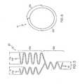
- Figure 1shows a portion of one embodiment of an expansion ring 20.
- the expansion ring 20extends circumferentially about the stent and forms a part of the tubular body of the stent.
- the expansion ring 20has a circumferential length and a longitudinal width.
- the expansion ring 20has a first circumferential section 22a and a second circumferential section 22b.
- the expansion ring 20has at least two circumferential sections 22. It is within the scope of the invention for the expansion ring 20 to have two, three, four, five, six, seven, eight or more circumferential sections 22.
- Each circumferential section 22has a longitudinal length equal to the longitudinal length of the expansion ring 20.
- each circumferential section 22has a circumferential length.
- the circumferential length of the expansion ring 20is equal to the sum of the circumferential lengths of each circumferential section 22 of the expansion ring 20.
- Each circumferential section 22also has a position about the circumference of the tubular body of the stent, a circumferential position.
- Figure 6is an end view of an expansion ring 20. If this view of the substantially circular tubular body is correlated to a clock, the circumferential position of the first circumferential section 22a would be from 12 to 3 while the circumferential position of the second circumferential section 22b would be from 3 to 12. Obviously, these positions are relative as the circumferential positions of the circumferential sections 22 depend on where 12 is determined to be located on the substantially circular tubular body. In addition, the circumferential positions depend upon the circumferential lengths of each circumferential section 22.
- the first circumferential section 22ahas one expansion column 24 while the second circumferential section 22b has two expansion columns 24a,b.
- the expansion column 24 of the first circumferential section 22ahas a longitudinal length (L1) no greater than the longitudinal length of the expansion ring 20.
- Figure 1shows an expansion ring where the expansion column 24 of the first circumferential section 22a has a longitudinal length L1 substantially equal to the longitudinal length of the expansion ring 20. In essence, the longitudinal length of the expansion ring 20 is equal to the circumferential section 22 of the expansion ring 20 with the greatest longitudinal length.
- the longitudinal lengths (L2,L3) of the expansion columns 24a,b of the second circumferential section 22b and the longitudinal gaps (G) between the expansion columns 24a,bhave a cumulative longitudinal length no greater than the longitudinal length of the expansion ring 20.
- the longitudinal gap (G)is the longitudinal length or distance between the distal end of the first expansion column 24a and the proximal end of the second expansion column 24b, as illustrated in Fig. 1 .
- the expansion columns 24a,b of the second circumferential section 22bhave a longitudinal length (L2, L3) less than the longitudinal length of the expansion column 24 of the first circumferential section 22a.
- strut 26awhich engages the second expansion column 24b of the second circumferential section 22b to the first circumferential section 22a, is longer than strut 26b which engages the first expansion column 24a of the second circumferential section 22b to the first circumferential section 22a.
- strut 26bis substantially the same length as the other expansion column struts 26. This difference in strut length 26a, 26b enables the expansion columns 24a,b of the second circumferential section 22b to be in phase with one another.
- expansion column peaks 28correlate with one another so that the expansion column peaks 28 are in the same direction, thereby forming a synchronized pattern.
- all the expansion column peaks 28 at a particular circumferential locationextend in one direction, e.g. distally, and all the expansion column peaks 28 at the adjacent circumferential location extend in a different location, e.g. proximally.
- expansion column peaks 28 at the same circumferential positionare 180 degrees out of phase with one another.
- the expansion column peaks 28 of one expansion columns 24aextends one direction, e.g. distally, while the expansion column peaks 28 of the adjacent expansion column 24b extends in the opposite direction, e.g. proximally.
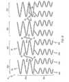
- Figure 2shows an embodiment where the longitudinal lengths of the expansion columns 24 of the first circumferential section 22a and the second circumferential section 22b are each less than the longitudinal length of the expansion ring 20.
- the longitudinal length of the expansion column 24 of the first circumferential section 22ais substantially equal to the longitudinal lengths of the expansion columns 24a,b of the second circumferential section 22b.
- Strut 26ais longer than the other struts 26 of the expansion column 24 of the first circumferential section 22a. This allows the expansion column 24 of the first circumferential section 22a to have a smaller longitudinal length and yet still engage the expansion columns 24a,b of the second circumferential section 22b.
- the struts 26b and 26chave different lengths which allow the two expansion columns 24a,b of the second circumferential section 22b to be in phase with one another.
- the second circumferential sections 22b of Figs. 1 and 2have two expansion columns 24a,b, it is within the scope of the invention for the second circumferential section 22b to have two, three, four, five, six, seven, eight, nine, ten or more expansion columns 24.
- Figure 3shows an embodiment where the second circumferential section 22b has three expansion columns 24a,b,c and
- Fig. 4shows an embodiment where the second circumferential section 22b has four expansion columns 24a,b,c,d.
- Each expansion column 24is comprised of struts 26 and peaks 28/valleys 29.
- the pattern formed by the struts and peaks 28/valleys 29 in Fig. 1is a serpentine pattern but any pattern can be formed by the struts and peaks 28/valleys 29.
- the expansion column 24 of Fig. 7has a zig-zag pattern.
- Each strut 26has a longitudinal length and the longitudinal length of the expansion column 24 depends on the length of the struts 26 forming the expansion column 24.
- the strut dimensions or aspect rationeed to be optimized.
- expansion columns with a longer circumferential lengthhave different strut dimensions, i.e.
- strut width and/or strut thicknessthan expansion columns with a shorter circumferential length. If the diameter of the strut is substantially constant, for example with struts that are round, then the strut diameter needs to be optimized. In addition, the strut peaks, including the peak radius need to be optimized.
- the expansion columns 24 of the second circumferential section 22bhave at least two longitudinal lengths L2,L3, as shown in Fig. 5 .
- the first expansion column 24ahas a longitudinal length L2 and the second expansion column 24b has a longitudinal length L3.
- the expansion column 24 of the first circumferential section 22ahas a longitudinal length of L1.
- the longitudinal lengths, L1, L2 and L3 of the expansion columns 24are different from one another.
- the longitudinal lengths L1, L2 and L3 of the expansion columns 24are substantially the same, as shown in Fig. 2 .
- the longitudinal lengths L1 and L2 of the expansion columns 24are substantially the same but less than the longitudinal length L3, as shown in Fig. 5 .
- the longitudinal lengths L2 and L3 of the expansion columns 24 of the second circumferential section 22bare substantially the same but less than longitudinal length L1, as shown in Fig. 1 .
- the combinationsare numerous when the second circumferential section 22b has more than two expansion columns 24.
- the whether the stent is in an unexpanded or an expanded statecan also affect the relationship between the longitudinal lengths of the first and second circumferential sections.
- the ratio of the longitudinal lengths between the first circumferential section 22a and the second circumferential section 22bchanges when the stent goes from the as cut state/ unexpanded state, to the deployed/expanded state.
- the longitudinal length of the first circumferential section 22ais different (either greater or smaller) than the circumferential length of the second circumferential section 22b in the unexpanded state, but in the expanded state, the longitudinal length of the first circumferential section 22a is equal to the longitudinal length of the second circumferential section 22b.
- the longitudinal length of the first circumferential section 22ain the expanded state, the longitudinal length of the first circumferential section 22a is different than the longitudinal length of the second circumferential section 22b but the difference between the two has changed (either a greater difference or a smaller difference).
- Figure 7is a flat view of an embodiment of a curve deployment section 10 of a stent.
- the stentconsists only of a curve deployment section 10. It is within the scope of the invention for a stent to have one, two, three, four, five, six or more curve deployment sections 10.
- the curve deployment section(s) 10can be positioned anywhere along the longitudinal length of the stent.
- the curve deployment section 10is engaged to the other section(s) of the stent by connectors 30 to form the complete stent.
- the curve deployment section 10can have any number of expansion rings 20. Thus, it is within the scope of the invention for the curve deployment section 10 to have one, two, three, four, five, six, seven, eight, nine, ten or more expansion rings 20. In the embodiment shown in Fig. 7 , the curve deployment section 10 has three expansion rings 20. In one embodiment, the curve deployment section 10 has at least one expansion ring 20.
- the three expansion rings 20a,b,care connected to one another at A and B to form a tubular structure.
- Connections A and Bare the only means by which the expansion rings 20a,b,c of the curve deployment section 10 are engaged to one another because there are no connector struts 30.
- this curve deployment section 10has the same attributes as the curve deployment section 10 of Fig. 10 , which is discussed in detail below.
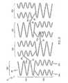
- Figure 8is an embodiment of a curve deployment section 10 with four expansion rings 20 with connectors 30 that engage adjacent expansion rings 20.
- Each of the four expansion rings 20has a first circumferential section 22a and a second circumferential section 22b.
- the first circumferential sections 22a and the second circumferential section 22b of each expansion ring 20have the same circumferential position.
- the expansion columns 24 of the first circumferential sections 22a of each expansion ring 20are in phase with one another.
- the second circumferential sections 22b of each expansion ring 20have two expansion columns 24a,b which are in phase with one another.
- the expansion columns 24a,b of adjacent expansion rings 20are in phase with one another.
- the similar alignment of the expansion columns 24maximizes flexibility and conformability in a single bending moment because the configurations of the four expansion rings 20 are identical.
- FIG. 9A second embodiment of the curve deployment section 10 is shown in Fig. 9 .
- the four expansion rings 20 of a curve deployment section 10have alternating configurations, i.e the first and third expansion ring 20a,c have the same configuration while the second and fourth expansion ring 20b,d have a configuration that is opposite of the first and third expansion ring 20a,c configuration.
- the adjacent expansion ring 20chas a second circumferential section 22b at the same circumferential position.
- This embodimentprovides more conformability in several bending moments due to the alternating configurations of the expansion rings 20.
- the conformability in a bending momentis provided by the circumferential sections(s) 22 of the expansion ring 20 that have at least two expansion columns 24.
- the configuration of the curve deployment section 10 shown in Fig. 9can be achieved in several ways.
- the first circumferential sections 22a and the second circumferential sections 22b of the expansion rings 20have the same circumferential length.
- the expansion rings 20have at least two circumferential sections 22, a first circumferential section 22a and a second circumferential section 22b with the substantially the same circumferential length and the first and second circumferential sections 22a,b alternate about the circumference.
- the first circumferential section 22ahas a smaller circumferential length than the second circumferential section 22b.
- the expansion rings 20have alternating configurations so that the first and third expansion ring 20a,c have the same configuration while the second expansion ring 20b has a different configuration.
- the first expansion ring 20ahas a first circumferential section 22a at a particular circumferential position while the second expansion ring 20b has a second circumferential section 22b at that same circumferential position.
- Alternating the configurations of the expansion rings 20can be continued for all the expansion rings 20 of a curve deployment section 10 or for as many of the expansion rings 20 of a curve deployment section 10 as desired.
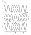
- the configuration of the curve deployment section 10 shown in Fig. 10can be achieved in several ways.
- the expansion rings 20 of the curve deployment sections 10have only two circumferential sections 22 where the first circumferential section 22a of the first and third expansion rings 20a,c has a substantially larger circumferential length than the second circumferential section while the first circumferential section 22a of the second expansion ring 20b has a substantially smaller circumferential length than the second circumferential section 22b.
- the expansion rings 20 of the curve deployment section 10have at least two circumferential sections 22, a first circumferential section 22a and a second circumferential section 22b where the lengths of the first and second circumferential sections 22a,b are substantially the same and the first and second circumferential sections 22a,b alternate about the circumference of the stent.
- FIG. 11An alternative embodiment of a curve deployment section 10 is shown in Fig. 11 .
- the expansion ring 20has only two circumferential sections 22, the first circumferential section 22a and the second circumferential section 22b.
- the first circumferential section 22ahas one expansion column 24 and the second circumferential section 22b has two expansion columns 24a,b.
- the first circumferential section 22ahas a shorter circumferential length than the second circumferential section 22b.
- the position of the first circumferential section 22avaries in the three expansion rings 20a,b,c so that the first circumferential sections 22a of the expansion rings 20a,b,c have a consecutive circumferential position in relation to the first circumferential section 22a of the adjacent expansion ring 20a,b,c.
- the circumferential positions of the first circumferential sections 22a of the three adjacent expansion rings 20a,b,cwere described in relation to a clock, as shown in Fig. 6 , the circumferential positions could span from 12 to 1, from 1 to 2, and from 2 to 3 for the first, second and third expansion rings 20a,b,c respectively.
- the first circumferential sections 22a of adjacent expansion rings 20circumferentially offset from one another by a predetermined circumferential distance.
- the circumferential positions of the first circumferential sections 22a of the three adjacent expansion rings 20were described in relation to a clock, the circumferential positions could span from 12 to 1, from 12:30 to 1:30 and from 1 to 2, respectively. Alternatively the positions could span from 12 to 1, from 2 to 3 and from 4 to 5, respectively.
- adjacent expansion rings 20are connected by at least one connector strut 30.
- the at least one connector strut 30is arranged so that flexibility of the curve deployment section 10 is minimized. A large number of connector struts 30 can minimize the flexibility of the curve deployment section 10.
- adjacent first circumferential sections 22aare engaged to one another by connectors 30, as illustrated in Fig. 8 .
- connectors 30engage adjacent circumferential sections 22a,b which are different from one another, as illustrated for example in Fig. 9 .
- the curve deployment section 10has connectors 30 between adjacent expansion rings 20 and between adjacent expansions columns 24 within a circumferential section 22 that has at least two expansion columns 24, as illustrated in Fig. 11 .
- a curve deployment section 10is engaged to another section of the stent by at least one connector 30.
- the connectors 30can have any shape and can engage adjacent expansion rings 20 in any manner. It is within the scope of the invention for the connector strut 30 to have any configuration, including but not limited to, straight, curvilinear, and zig-zag. In Fig. 8 , the connectors 30 have at least one curve 32. A curve may be sharp, as in a zig-zag, or more rounded, like the curves 32 in the first connector 30a.
- the first connector 30aextends from an expansion column strut 26 on one expansion ring 20a to an expansion column strut 26 on the adjacent expansion ring 20b.
- the second connector 30bextends from an expansion column peak 28 on one expansion ring 20b to an expansion column peak 28 on the adjacent expansion ring 20c, a peak to peak connector.
- the second connector 30bhas two curves 32 and one straight segment 34.
- the third connector 30cextends from an expansion column peak 28 on one expansion ring 20c to an expansion column valley 29 on the adjacent expansion ring 20d, a peak to valley conenctor.
- the third connector 30chas two curves 32 and one straight segment 34. In Fig. 9 , all the connectors 30 are straight and have no curves 32.
- Connectors 30a and 30cextend from an expansion column peak 28 on one expansion ring 20 to an expansion column peak 28 on the adjacent expansion ring 20.
- Connector 30bextends from an expansion column peak 28 on one expansion ring 20 to an expansion column valley 29 on the adjacent expansion ring 20. It is also within the scope of the invention for the connector to be a valley to valley connector.
- variable number of expansion columns 24can provide the stent with several advantages.
- a variable number of expansion columns 24, about the circumference of the stentincreases the uniformity of drug delivery in a curved portion of a blood vessel due to the decreased longitudinal separation of adjacent expansion columns 24.
- a variable number of expansion columns 24, about the circumference of the stentincreases the amount of scaffolding in a curved portion of a blood vessel due to the decreased longitudinal separation of adjacent expansion columns 24.
- the longitudinal flexibility of the stentis increased due to the increased number of expansion columns 24 per unit of longitudinal length of the stent.
- the inventive stentsmay be made from any suitable biocompatible materials including one or more polymers, one or more metals or combinations of polymer(s) and metal(s).
- suitable materialsinclude biodegradable materials that are also biocompatible.
- biodegradableis meant that a material will undergo breakdown or decomposition into harmless compounds as part of a normal biological process.
- Suitable biodegradable materialsinclude polylactic acid, polyglycolic acid (PGA), collagen or other connective proteins or natural materials, polycaprolactone, hylauric acid, adhesive proteins, co-polymers of these materials as well as composites and combinations thereof and combinations of other biodegradable polymers.
- Other polymers that may be usedinclude polyester and polycarbonate copolymers.
- suitable metalsinclude, but are not limited to, stainless steel, titanium, tantalum, platinum, tungsten, gold and alloys of any of the above-mentioned metals.
- suitable alloysinclude platinum-iridium alloys, cobalt-chromium alloys including Elgiloy and Phynox, MP35N alloy and nickel-titanium alloys, for example, Nitinol.
- the inventive stentsmay be made of shape memory materials such as superelastic Nitinol or spring steel, or may be made of materials which are plastically deformable.
- shape memory materialssuch as superelastic Nitinol or spring steel, or may be made of materials which are plastically deformable.
- the stentmay be provided with a memorized shape and then deformed to a reduced diameter shape. The stent may restore itself to its memorized shape upon being heated to a transition temperature and having any restraints removed therefrom.
- inventive stentsmay be created by methods including cutting or etching a design from a tubular stock, from a flat sheet which is cut or etched and which is subsequently rolled. Any other suitable technique which is known in the art or which is subsequently developed may also be used to manufacture the inventive stents disclosed herein.
- the stent, the delivery system or other portion of the assemblymay include one or more areas, bands, coatings, members, etc. that is (are) detectable by imaging modalities such as X-Ray, MRI, ultrasound, etc.
- imaging modalitiessuch as X-Ray, MRI, ultrasound, etc.
- at least a portion of the stent and/or adjacent assemblyis at least partially radiopaque.
- the at least a portion of the stentis configured to include one or more mechanisms for the delivery of a therapeutic agent.
- the agentwill be in the form of a coating or other layer (or layers) of material placed on a surface region of the stent, which is adapted to be released at the site of the stent's implantation or areas adjacent thereto.
- a therapeutic agentmay be a drug or other pharmaceutical product such as non-genetic agents, genetic agents, cellular material, etc.
- suitable non-genetic therapeutic agentsinclude but are not limited to: anti-thrombogenic agents such as heparin, heparin derivatives, vascular cell growth promoters, growth factor inhibitors, Paclitaxel, etc.
- an agentincludes a genetic therapeutic agent, such a genetic agent may include but is not limited to: DNA, RNA and their respective derivatives and/or components; hedgehog proteins, etc.
- the cellular materialmay include but is not limited to: cells of human origin and/or non-human origin as well as their respective components and/or derivatives thereof.
- the polymer agentmay be a polystyrene-polyisobutylene-polystyrene triblock copolymer (SIBS), polyethylene oxide, silicone rubber and/or any other suitable substrate.
- SIBSpolystyrene-polyisobutylene-polystyrene triblock copolymer
- any dependent claim which followsshould be taken as alternatively written in a multiple dependent form from all prior claims which possess all antecedents referenced in such dependent claim if such multiple dependent format is an accepted format within the jurisdiction (e.g. each claim depending directly from claim 1 should be alternatively taken as depending from all previous claims).
- each claim depending directly from claim 1should be alternatively taken as depending from all previous claims.
- the following dependent claimsshould each be also taken as alternatively written in each singly dependent claim format which creates a dependency from a prior antecedent-possessing claim other than the specific claim listed in such dependent claim below.
Landscapes
- Health & Medical Sciences (AREA)
- Engineering & Computer Science (AREA)
- Biomedical Technology (AREA)
- Heart & Thoracic Surgery (AREA)
- Life Sciences & Earth Sciences (AREA)
- Cardiology (AREA)
- Oral & Maxillofacial Surgery (AREA)
- Transplantation (AREA)
- Physics & Mathematics (AREA)
- Vascular Medicine (AREA)
- Optics & Photonics (AREA)
- Animal Behavior & Ethology (AREA)
- General Health & Medical Sciences (AREA)
- Public Health (AREA)
- Veterinary Medicine (AREA)
- Prostheses (AREA)
- Media Introduction/Drainage Providing Device (AREA)
Abstract
Description
- In some embodiments this invention relates to implantable medical devices
- A stent is a medical device introduced to a body lumen and is well known in the art. Typically, a stent is implanted in a blood vessel at the site of a stenosis or aneurysm endoluminally, i.e. by so-called "minimally invasive techniques" in which the stent in a radially reduced configuration, optionally restrained in a radially compressed configuration by a sheath and/or catheter, is delivered by a stent delivery system or "introducer" to the site where it is required. The introducer may enter the body from an access location outside the body, such as through the patient's skin, or by a "cut down" technique in which the entry blood vessel is exposed by minor surgical means.
- Stents, grafts, stent-grafts, vena cava filters, expandable frameworks, and similar implantable medical devices, collectively referred to hereinafter as stents, are radially expandable endoprostheses which are typically intravascular implants capable of being implanted transluminally and enlarged radially after being introduced percutaneously. Stents may be implanted in a variety of body lumens or vessels such as within the vascular system, urinary tracts, bile ducts, fallopian tubes, coronary vessels, secondary vessels, etc. They may be self-expanding, expanded by an internal radial force, such as when mounted on a balloon, or a combination of self-expanding and balloon expandable (hybrid expandable).
- Stents may be created by methods including cutting or etching a design from a tubular stock, from a flat sheet which is cut or etched and which is subsequently rolled or from one or more interwoven wires or braids.
- Document
EP 1472 990 A1 discloses the features of the preamble of claim 1. More particularly, it shows a stent graft including a stent graft material of cylindrical shape and tapered stent springs coupled to the stent graft material. The stent springs include first stent cells and second stent cells coupled thereto and being smaller than the first stent cells, thereby defining a tapered shape. The stent graft shall be placed in a curved segment of a tortuous body lumen and rotationally positioned such that the smallest stent cell of each tapered stent spring is placed at an inside radius of the curved segment. - Without limiting the scope of the invention a brief summary of some of the claimed embodiments of the invention is set forth below. Additional details of the summarized embodiments of the invention and/or additional embodiments of the invention may be found in the Detailed Description of the Invention below.
- In at least one embodiment, a stent has at least one curve deployment section. The curve deployment section has at least one expansion ring. The expansion ring has a circumferential length, a longitudinal length and at least two circumferential sections. Each circumferential section has a circumferential length so that the cumulative length equals the overall circumferential length of the expansion ring. The first circumferential section has one expansion column and the second circumferential section has at least two expansion columns.
- In one embodiment, the at least two expansion columns of the second circumferential section are in phase with one another. In one embodiment, the at least two expansion columns of the second circumferential section are out of phase with one another.
- In one embodiment, the longitudinal length of the expansion column of the first circumferential section is greater than the longitudinal lengths of the at least two expansion columns of the second circumferential section. In one embodiment, the longitudinal length of the expansion column of the first circumferential section is substantially the same as the longitudinal lengths of the at least two expansion columns of the second circumferential section.
- In one embodiment, the curve deployment section has at least two expansion rings which are engaged to one another by connector struts.
- These and other embodiments which characterize the invention are pointed out with particularity in the claims annexed hereto and forming a part hereof. However, for further understanding of the invention, its advantages and objectives obtained by its use, reference can be made to the drawings which form a further part hereof and the accompanying descriptive matter, in which there is illustrated and described an embodiments of the invention.
- A detailed description of the invention is hereafter described with specific reference being made to the drawings.
FIG. 1 is a flat view of a portion an embodiment of an expansion ring.FIG. 2 is a flat view of a portion of an alternative embodiment of an expansion ring.FIG. 3 is a flat view of a portion of an embodiment of an expansion ring with three expansion columns in the second circumferential section.FIG. 4 is a flat view of a portion of an embodiment of an expansion ring with four expansion columns in the second circumferential section.FIG. 5 is a flat view of a portion of an embodiment of an expansion ring where the expansion columns in the second circumferential section have different longitudinal lengths.FIG. 6 is an end view of an embodiment of an expansion ring showing the circumferential positions of the two circumferential sections.FIG. 7 is flat view of an embodiment of a curve deployment section without connectors so that the three expansion rings are connected only at points A and B.FIG. 8 is a flat view of an embodiment of a curve deployment section with connectors.FIG. 9 is a flat view of an alternative embodiment of a curve deployment section with connectors.FIG. 10 is a flat view of an alternative embodiment of a curve deployment section with connectors.FIG. 11 is a flat view of an alternative embodiment of a curve deployment section with connectors.FIG. 12 is a view of an embodiment of a curve deployment section in an expanded state within a vessel curve.- While this invention may be embodied in many different forms, there are described in detail herein specific embodiments of the invention. This description is an exemplification of the principles of the invention and is not intended to limit the invention to the particular embodiments illustrated.
- For the purposes of this disclosure, like reference numerals in the figures shall refer to like features unless otherwise indicated.
- In at least one embodiment, a stent has at least one
curve deployment section 10. Acurve deployment section 10 is composed of at least oneexpansion ring 20 which is a radially expandable cylindrical element that extends about the circumference of the stent and has at least twocircumferential sections 22. Eachcircumferential section 22 has at least oneexpansion column 24, with adjacentcircumferential sections 22 within anexpansion ring 20 have different a number ofexpansion columns 24. Thus, anexpansion ring 20 has a variable number ofexpansion columns 24 about the circumference of the stent. - The
expansion ring 20 can have a variety of configurations.Figure 1 shows a portion of one embodiment of anexpansion ring 20. Theexpansion ring 20 extends circumferentially about the stent and forms a part of the tubular body of the stent. Thus, theexpansion ring 20 has a circumferential length and a longitudinal width. In this embodiment, theexpansion ring 20 has a firstcircumferential section 22a and a secondcircumferential section 22b. In at least one embodiment, theexpansion ring 20 has at least twocircumferential sections 22. It is within the scope of the invention for theexpansion ring 20 to have two, three, four, five, six, seven, eight or morecircumferential sections 22. - Each
circumferential section 22 has a longitudinal length equal to the longitudinal length of theexpansion ring 20. In addition, eachcircumferential section 22 has a circumferential length. Thus, the circumferential length of theexpansion ring 20 is equal to the sum of the circumferential lengths of eachcircumferential section 22 of theexpansion ring 20. Eachcircumferential section 22 also has a position about the circumference of the tubular body of the stent, a circumferential position.Figure 6 is an end view of anexpansion ring 20. If this view of the substantially circular tubular body is correlated to a clock, the circumferential position of the firstcircumferential section 22a would be from 12 to 3 while the circumferential position of the secondcircumferential section 22b would be from 3 to 12. Obviously, these positions are relative as the circumferential positions of thecircumferential sections 22 depend on where 12 is determined to be located on the substantially circular tubular body. In addition, the circumferential positions depend upon the circumferential lengths of eachcircumferential section 22. - The first
circumferential section 22a has oneexpansion column 24 while the secondcircumferential section 22b has twoexpansion columns 24a,b. Theexpansion column 24 of the firstcircumferential section 22a has a longitudinal length (L1) no greater than the longitudinal length of theexpansion ring 20.Figure 1 shows an expansion ring where theexpansion column 24 of the firstcircumferential section 22a has a longitudinal length L1 substantially equal to the longitudinal length of theexpansion ring 20. In essence, the longitudinal length of theexpansion ring 20 is equal to thecircumferential section 22 of theexpansion ring 20 with the greatest longitudinal length. - Similarly, the longitudinal lengths (L2,L3) of the
expansion columns 24a,b of the secondcircumferential section 22b and the longitudinal gaps (G) between theexpansion columns 24a,b have a cumulative longitudinal length no greater than the longitudinal length of theexpansion ring 20. The longitudinal gap (G) is the longitudinal length or distance between the distal end of thefirst expansion column 24a and the proximal end of thesecond expansion column 24b, as illustrated inFig. 1 . Also, theexpansion columns 24a,b of the secondcircumferential section 22b have a longitudinal length (L2, L3) less than the longitudinal length of theexpansion column 24 of the firstcircumferential section 22a. - Also note in
Fig. 1 , thatstrut 26a, which engages thesecond expansion column 24b of the secondcircumferential section 22b to the firstcircumferential section 22a, is longer thanstrut 26b which engages thefirst expansion column 24a of the secondcircumferential section 22b to the firstcircumferential section 22a. Note thatstrut 26b is substantially the same length as the other expansion column struts 26. This difference instrut length expansion columns 24a,b of the secondcircumferential section 22b to be in phase with one another. - When
expansion columns 24 are in phase, the expansion column peaks 28 correlate with one another so that the expansion column peaks 28 are in the same direction, thereby forming a synchronized pattern. Thus for example, all the expansion column peaks 28 at a particular circumferential location extend in one direction, e.g. distally, and all the expansion column peaks 28 at the adjacent circumferential location extend in a different location, e.g. proximally. - It is also within the scope of the invention for the expansion columns to be out of phase with one another, as illustrated in
Fig. 7 . Therefore, expansion column peaks 28 at the same circumferential position are 180 degrees out of phase with one another. Thus, the expansion column peaks 28 of oneexpansion columns 24a extends one direction, e.g. distally, while the expansion column peaks 28 of theadjacent expansion column 24b extends in the opposite direction, e.g. proximally. Figure 2 shows an embodiment where the longitudinal lengths of theexpansion columns 24 of the firstcircumferential section 22a and the secondcircumferential section 22b are each less than the longitudinal length of theexpansion ring 20. In addition, the longitudinal length of theexpansion column 24 of the firstcircumferential section 22a is substantially equal to the longitudinal lengths of theexpansion columns 24a,b of the secondcircumferential section 22b.Strut 26a is longer than theother struts 26 of theexpansion column 24 of the firstcircumferential section 22a. This allows theexpansion column 24 of the firstcircumferential section 22a to have a smaller longitudinal length and yet still engage theexpansion columns 24a,b of the secondcircumferential section 22b. Similar toFig. 1 , thestruts expansion columns 24a,b of the secondcircumferential section 22b to be in phase with one another.- Although the second
circumferential sections 22b ofFigs. 1 and 2 have twoexpansion columns 24a,b, it is within the scope of the invention for the secondcircumferential section 22b to have two, three, four, five, six, seven, eight, nine, ten ormore expansion columns 24.Figure 3 shows an embodiment where the secondcircumferential section 22b has threeexpansion columns 24a,b,c andFig. 4 shows an embodiment where the secondcircumferential section 22b has fourexpansion columns 24a,b,c,d. - Each
expansion column 24 is comprised ofstruts 26 andpeaks 28/valleys 29. The pattern formed by the struts and peaks 28/valleys 29 inFig. 1 is a serpentine pattern but any pattern can be formed by the struts and peaks 28/valleys 29. For example, theexpansion column 24 ofFig. 7 has a zig-zag pattern. Eachstrut 26 has a longitudinal length and the longitudinal length of theexpansion column 24 depends on the length of thestruts 26 forming theexpansion column 24. In order for the expansion columns to expand evenly, the strut dimensions or aspect ratio need to be optimized. Thus, expansion columns with a longer circumferential length have different strut dimensions, i.e. strut width and/or strut thickness, than expansion columns with a shorter circumferential length. If the diameter of the strut is substantially constant, for example with struts that are round, then the strut diameter needs to be optimized. In addition, the strut peaks, including the peak radius need to be optimized. - In at least one embodiment, the
expansion columns 24 of the secondcircumferential section 22b have at least two longitudinal lengths L2,L3, as shown inFig. 5 . Thefirst expansion column 24a has a longitudinal length L2 and thesecond expansion column 24b has a longitudinal length L3. Theexpansion column 24 of the firstcircumferential section 22a has a longitudinal length of L1. - There can be many relationships between the longitudinal lengths, L1, L2 and L3 of the
expansion columns 24. In one embodiment, the longitudinal lengths, L1, L2 and L3 of theexpansion columns 24 are different from one another. In at least one embodiment, the longitudinal lengths L1, L2 and L3 of theexpansion columns 24 are substantially the same, as shown inFig. 2 . In at least one embodiment, the longitudinal lengths L1 and L2 of theexpansion columns 24 are substantially the same but less than the longitudinal length L3, as shown inFig. 5 . In at least one embodiment, the longitudinal lengths L2 and L3 of theexpansion columns 24 of the secondcircumferential section 22b are substantially the same but less than longitudinal length L1, as shown inFig. 1 . Obviously, the combinations are numerous when the secondcircumferential section 22b has more than twoexpansion columns 24. - In addition; the whether the stent is in an unexpanded or an expanded state can also affect the relationship between the longitudinal lengths of the first and second circumferential sections. In at least one embodiment, the ratio of the longitudinal lengths between the first
circumferential section 22a and the secondcircumferential section 22b changes when the stent goes from the as cut state/ unexpanded state, to the deployed/expanded state. Thus, in one embodiment, the longitudinal length of the firstcircumferential section 22a is different (either greater or smaller) than the circumferential length of the secondcircumferential section 22b in the unexpanded state, but in the expanded state, the longitudinal length of the firstcircumferential section 22a is equal to the longitudinal length of the secondcircumferential section 22b. In one embodiment, in the expanded state, the longitudinal length of the firstcircumferential section 22a is different than the longitudinal length of the secondcircumferential section 22b but the difference between the two has changed (either a greater difference or a smaller difference). Figure 7 is a flat view of an embodiment of acurve deployment section 10 of a stent. In at least one embodiment, the stent consists only of acurve deployment section 10. It is within the scope of the invention for a stent to have one, two, three, four, five, six or morecurve deployment sections 10. The curve deployment section(s) 10 can be positioned anywhere along the longitudinal length of the stent. Thecurve deployment section 10 is engaged to the other section(s) of the stent byconnectors 30 to form the complete stent.- The
curve deployment section 10 can have any number of expansion rings 20. Thus, it is within the scope of the invention for thecurve deployment section 10 to have one, two, three, four, five, six, seven, eight, nine, ten or more expansion rings 20. In the embodiment shown inFig. 7 , thecurve deployment section 10 has three expansion rings 20. In one embodiment, thecurve deployment section 10 has at least oneexpansion ring 20. - In this embodiment, the three
expansion rings 20a,b,c are connected to one another at A and B to form a tubular structure. Connections A and B are the only means by which the expansion rings 20a,b,c of thecurve deployment section 10 are engaged to one another because there are no connector struts 30. Except for the zig-zag pattern and lack of connector struts 30, thiscurve deployment section 10 has the same attributes as thecurve deployment section 10 ofFig. 10 , which is discussed in detail below. Figure 8 is an embodiment of acurve deployment section 10 with four expansion rings 20 withconnectors 30 that engage adjacent expansion rings 20. Each of the four expansion rings 20 has a firstcircumferential section 22a and a secondcircumferential section 22b. The firstcircumferential sections 22a and the secondcircumferential section 22b of eachexpansion ring 20 have the same circumferential position. Theexpansion columns 24 of the firstcircumferential sections 22a of eachexpansion ring 20 are in phase with one another. The secondcircumferential sections 22b of eachexpansion ring 20 have twoexpansion columns 24a,b which are in phase with one another. In addition, theexpansion columns 24a,b of adjacent expansion rings 20 are in phase with one another. In this embodiment, the similar alignment of theexpansion columns 24 maximizes flexibility and conformability in a single bending moment because the configurations of the four expansion rings 20 are identical.- A second embodiment of the
curve deployment section 10 is shown inFig. 9 . In this embodiment, the four expansion rings 20 of acurve deployment section 10 have alternating configurations, i.e the first andthird expansion ring 20a,c have the same configuration while the second andfourth expansion ring 20b,d have a configuration that is opposite of the first andthird expansion ring 20a,c configuration. Thus, where oneexpansion ring 20a has a firstcircumferential section 22a at a particular circumferential position, theadjacent expansion ring 20c has a secondcircumferential section 22b at the same circumferential position. This embodiment provides more conformability in several bending moments due to the alternating configurations of the expansion rings 20. The conformability in a bending moment is provided by the circumferential sections(s) 22 of theexpansion ring 20 that have at least twoexpansion columns 24. - The configuration of the
curve deployment section 10 shown inFig. 9 can be achieved in several ways. In at least one embodiment, the firstcircumferential sections 22a and the secondcircumferential sections 22b of the expansion rings 20 have the same circumferential length. In at least one embodiment, the expansion rings 20 have at least twocircumferential sections 22, a firstcircumferential section 22a and a secondcircumferential section 22b with the substantially the same circumferential length and the first and secondcircumferential sections 22a,b alternate about the circumference. In at least one embodiment, the firstcircumferential section 22a has a smaller circumferential length than the secondcircumferential section 22b. - The order and design of the
expansion columns 24 can be varied to optimize scaffolding depending upon the anatomical application or extent of disease as is shown inFigs. 10 and11 . InFig. 10 , the expansion rings 20 have alternating configurations so that the first andthird expansion ring 20a,c have the same configuration while thesecond expansion ring 20b has a different configuration. Thus, thefirst expansion ring 20a has a firstcircumferential section 22a at a particular circumferential position while thesecond expansion ring 20b has a secondcircumferential section 22b at that same circumferential position. Alternating the configurations of the expansion rings 20 can be continued for all the expansion rings 20 of acurve deployment section 10 or for as many of the expansion rings 20 of acurve deployment section 10 as desired. - The configuration of the
curve deployment section 10 shown inFig. 10 can be achieved in several ways. In at least one embodiment, the expansion rings 20 of thecurve deployment sections 10 have only twocircumferential sections 22 where the firstcircumferential section 22a of the first andthird expansion rings 20a,c has a substantially larger circumferential length than the second circumferential section while the firstcircumferential section 22a of thesecond expansion ring 20b has a substantially smaller circumferential length than the secondcircumferential section 22b. - In at least one embodiment, the expansion rings 20 of the
curve deployment section 10 have at least twocircumferential sections 22, a firstcircumferential section 22a and a secondcircumferential section 22b where the lengths of the first and secondcircumferential sections 22a,b are substantially the same and the first and secondcircumferential sections 22a,b alternate about the circumference of the stent. - An alternative embodiment of a
curve deployment section 10 is shown inFig. 11 . In this embodiment, theexpansion ring 20 has only twocircumferential sections 22, the firstcircumferential section 22a and the secondcircumferential section 22b. The firstcircumferential section 22a has oneexpansion column 24 and the secondcircumferential section 22b has twoexpansion columns 24a,b. The firstcircumferential section 22a has a shorter circumferential length than the secondcircumferential section 22b. In addition, the position of the firstcircumferential section 22a varies in the threeexpansion rings 20a,b,c so that the firstcircumferential sections 22a of the expansion rings 20a,b,c have a consecutive circumferential position in relation to the firstcircumferential section 22a of theadjacent expansion ring 20a,b,c. Thus, if the circumferential positions of the firstcircumferential sections 22a of the threeadjacent expansion rings 20a,b,c were described in relation to a clock, as shown inFig. 6 , the circumferential positions could span from 12 to 1, from 1 to 2, and from 2 to 3 for the first, second andthird expansion rings 20a,b,c respectively. - In at least one embodiment, the first
circumferential sections 22a of adjacent expansion rings 20 circumferentially offset from one another by a predetermined circumferential distance. In this embodiment, if the circumferential positions of the firstcircumferential sections 22a of the three adjacent expansion rings 20 were described in relation to a clock, the circumferential positions could span from 12 to 1, from 12:30 to 1:30 and from 1 to 2, respectively. Alternatively the positions could span from 12 to 1, from 2 to 3 and from 4 to 5, respectively. - In at least one embodiment, adjacent expansion rings 20 are connected by at least one
connector strut 30. In some embodiments, the at least oneconnector strut 30 is arranged so that flexibility of thecurve deployment section 10 is minimized. A large number of connector struts 30 can minimize the flexibility of thecurve deployment section 10. In at least one embodiment, adjacent firstcircumferential sections 22a are engaged to one another byconnectors 30, as illustrated inFig. 8 . In at least one embodiment,connectors 30 engage adjacentcircumferential sections 22a,b which are different from one another, as illustrated for example inFig. 9 . In at least one embodiment, thecurve deployment section 10 hasconnectors 30 between adjacent expansion rings 20 and betweenadjacent expansions columns 24 within acircumferential section 22 that has at least twoexpansion columns 24, as illustrated inFig. 11 . In at least one embodiment, acurve deployment section 10 is engaged to another section of the stent by at least oneconnector 30. - The
connectors 30 can have any shape and can engage adjacent expansion rings 20 in any manner. It is within the scope of the invention for theconnector strut 30 to have any configuration, including but not limited to, straight, curvilinear, and zig-zag. InFig. 8 , theconnectors 30 have at least onecurve 32. A curve may be sharp, as in a zig-zag, or more rounded, like thecurves 32 in thefirst connector 30a. Thefirst connector 30a extends from anexpansion column strut 26 on oneexpansion ring 20a to anexpansion column strut 26 on theadjacent expansion ring 20b. Thesecond connector 30b extends from anexpansion column peak 28 on oneexpansion ring 20b to anexpansion column peak 28 on theadjacent expansion ring 20c, a peak to peak connector. Thesecond connector 30b has twocurves 32 and onestraight segment 34. Thethird connector 30c extends from anexpansion column peak 28 on oneexpansion ring 20c to anexpansion column valley 29 on theadjacent expansion ring 20d, a peak to valley conenctor. Thethird connector 30c has twocurves 32 and onestraight segment 34. InFig. 9 , all theconnectors 30 are straight and have nocurves 32.Connectors expansion column peak 28 on oneexpansion ring 20 to anexpansion column peak 28 on theadjacent expansion ring 20.Connector 30b extends from anexpansion column peak 28 on oneexpansion ring 20 to anexpansion column valley 29 on theadjacent expansion ring 20. It is also within the scope of the invention for the connector to be a valley to valley connector. - An illustration of how a
curve deployment section 10 would look in an expanded state within acurved vessel 5 is shown inFig. 12 . When thecurve deployment section 10 is in an expanded state, the variable number ofexpansion columns 24 can provide the stent with several advantages. In some embodiments, a variable number ofexpansion columns 24, about the circumference of the stent, increases the uniformity of drug delivery in a curved portion of a blood vessel due to the decreased longitudinal separation ofadjacent expansion columns 24. In some embodiments, a variable number ofexpansion columns 24, about the circumference of the stent, increases the amount of scaffolding in a curved portion of a blood vessel due to the decreased longitudinal separation ofadjacent expansion columns 24. In some embodiments, the longitudinal flexibility of the stent is increased due to the increased number ofexpansion columns 24 per unit of longitudinal length of the stent. - The inventive stents may be made from any suitable biocompatible materials including one or more polymers, one or more metals or combinations of polymer(s) and metal(s). Examples of suitable materials include biodegradable materials that are also biocompatible. By biodegradable is meant that a material will undergo breakdown or decomposition into harmless compounds as part of a normal biological process. Suitable biodegradable materials include polylactic acid, polyglycolic acid (PGA), collagen or other connective proteins or natural materials, polycaprolactone, hylauric acid, adhesive proteins, co-polymers of these materials as well as composites and combinations thereof and combinations of other biodegradable polymers. Other polymers that may be used include polyester and polycarbonate copolymers. Examples of suitable metals include, but are not limited to, stainless steel, titanium, tantalum, platinum, tungsten, gold and alloys of any of the above-mentioned metals. Examples of suitable alloys include platinum-iridium alloys, cobalt-chromium alloys including Elgiloy and Phynox, MP35N alloy and nickel-titanium alloys, for example, Nitinol.
- The inventive stents may be made of shape memory materials such as superelastic Nitinol or spring steel, or may be made of materials which are plastically deformable. In the case of shape memory materials, the stent may be provided with a memorized shape and then deformed to a reduced diameter shape. The stent may restore itself to its memorized shape upon being heated to a transition temperature and having any restraints removed therefrom.
- The inventive stents may be created by methods including cutting or etching a design from a tubular stock, from a flat sheet which is cut or etched and which is subsequently rolled. Any other suitable technique which is known in the art or which is subsequently developed may also be used to manufacture the inventive stents disclosed herein.
- In some embodiments the stent, the delivery system or other portion of the assembly may include one or more areas, bands, coatings, members, etc. that is (are) detectable by imaging modalities such as X-Ray, MRI, ultrasound, etc. In some embodiments at least a portion of the stent and/or adjacent assembly is at least partially radiopaque.
- In some embodiments the at least a portion of the stent is configured to include one or more mechanisms for the delivery of a therapeutic agent. Often the agent will be in the form of a coating or other layer (or layers) of material placed on a surface region of the stent, which is adapted to be released at the site of the stent's implantation or areas adjacent thereto.
- A therapeutic agent may be a drug or other pharmaceutical product such as non-genetic agents, genetic agents, cellular material, etc. Some examples of suitable non-genetic therapeutic agents include but are not limited to: anti-thrombogenic agents such as heparin, heparin derivatives, vascular cell growth promoters, growth factor inhibitors, Paclitaxel, etc. Where an agent includes a genetic therapeutic agent, such a genetic agent may include but is not limited to: DNA, RNA and their respective derivatives and/or components; hedgehog proteins, etc. Where a therapeutic agent includes cellular material, the cellular material may include but is not limited to: cells of human origin and/or non-human origin as well as their respective components and/or derivatives thereof. Where the therapeutic agent includes a polymer agent, the polymer agent may be a polystyrene-polyisobutylene-polystyrene triblock copolymer (SIBS), polyethylene oxide, silicone rubber and/or any other suitable substrate.
- The above disclosure is intended to be illustrative and not exhaustive. This description will suggest many variations and alternatives to one of ordinary skill in this art. The various elements shown in the individual figures and described above may be combined or modified for combination as desired. All these alternatives and variations are intended to be included within the scope of the claims where the term "comprising" means "including, but not limited to".
- Further, the particular features presented in the dependent claims can be combined with each other in other manners within the scope of the invention such that the invention should be recognized as also specifically directed to other embodiments having any other possible combination of the features of the dependent claims. For instance, for purposes of claim publication, any dependent claim which follows should be taken as alternatively written in a multiple dependent form from all prior claims which possess all antecedents referenced in such dependent claim if such multiple dependent format is an accepted format within the jurisdiction (e.g. each claim depending directly from claim 1 should be alternatively taken as depending from all previous claims). In jurisdictions where multiple dependent claim formats are restricted, the following dependent claims should each be also taken as alternatively written in each singly dependent claim format which creates a dependency from a prior antecedent-possessing claim other than the specific claim listed in such dependent claim below.
- This completes the description of the invention. Those skilled in the art may recognize other equivalents to the specific embodiment described herein which equivalents are intended to be encompassed by the claims attached hereto.
Claims (15)
- A stent, comprising: at least one curve deployment section (10), the at least one curve deployment (10) section comprising at least one expansion ring (20), the at least one expansion ring (20) having a circumferential length, a longitudinal length and comprising a first circumferential section (22a) and a second circumferential section (22b), the first circumferential section (22a) comprising an expansion column (24), the second circumferential section (22b) comprising at least two expansion columns (24) longitudinally offset from one another, the expansion column (24) of the first circumferential section (22a) engaged to the at least two expansion (24) columns of the second circumferential section (22b), wherein each expansion column (24) comprises a plurality of peaks (28) and/or a plurality of valleys (29),characterised in that adjacent circumferential sections (22a, 22b) within the expansion ring (20) have a different number of expansion columns (24).
- The stent of claim 1, each expansion column (24) having a longitudinal length, the longitudinal length of each of the at least two expansion columns (24) of the second circumferential (22b) section less than the longitudinal length of the expansion ring (20).
- The stent of claim 2, the longitudinal length of the expansion column (24) of the first circumferential section (22a) substantially equal to the longitudinal length of the expansion ring (20).
- The stent of claim 2, the longitudinal length of the expansion column (24) of the first circumferential section (22a) substantially equal to the longitudinal length of the at least two expansion columns (24) of the second circumferential section (22b).
- The stent of claim 1, further comprising at least one connector strut (30), the at least one connector strut (30) engaging adjacent expansion rings (20).
- The stent of claim 1, further comprising at least one connector strut (30), the at least one connector strut (30) engaging adjacent expansion columns (24) of the second circumferential section (22b).
- The stent of claim 1, each of the circumferential sections (22a, 22b) having a circumferential position, the first circumferential sections (22a) of each of the at least one expansion ring (20) having the same circumferential position and the second circumferential sections (22b) of each of the at least one expansion ring (20) having the same circumferential position.
- The stent of claim 7, the first circumferential sections (22a) being in phase and the second circumferential sections (22b) being in phase.
- The stent of claim 1, the at least one curve deployment (10) section comprising a first expansion ring (20a), a second expansion ring (20b), a third expansion ring (20c) and a fourth expansion ring (20d), each of the circumferential sections (22a, 22b) having a circumferential position, the first circumferential sections (22a) of the first and third expansion rings (20a, 20c) having the same circumferential position as the second circumferential sections (22b) of the second and fourth expansion rings (20b, 20d), the second circumferential sections (22b)of the first and third expansion rings (20a, 20c) having the same circumferential position as the first circumferential sections (22a) of the second and fourth expansion rings (20b, 20d).
- The stent of claim 9, the first circumferential sections (22a) being in phase and the second circumferential sections (22b) being in phase.
- The stent of claim 1, each of the at least one expansion rings (20) having alternating first and second circumferential sections (22a, 22b), each of the circumferential sections (22a, 22b) having a circumferential position, expansion columns (24) of adjacent expansion rings (20) having alternating first and second circumferential sections (22a, 22b) at the same circumferential positions.
- The stent of claim 11, the first circumferential sections (22a) being in phase and the second circumferential sections (22b) being in phase.
- The stent of claim 11, the second circumferential section (22b) having two expansion columns (24), the two expansion columns (24) out of phase with each other.
- The stent of claim 11, further comprising at least one connecting strut (30), the at least one connector strut (30) engaging adjacent expansion rings (20).
- The stent of claim 1, the first circumferential section (22a) of each of the at least one expansion rings (20) having consecutive circumferential positions.
Applications Claiming Priority (3)
| Application Number | Priority Date | Filing Date | Title |
|---|---|---|---|
| US81801206P | 2006-06-30 | 2006-06-30 | |
| PCT/US2007/011845WO2008005111A1 (en) | 2006-06-30 | 2007-05-17 | Stent design with variable expansion columns along circumference |
| US11/749,855US8236044B2 (en) | 2006-06-30 | 2007-05-17 | Stent design with variable expansion columns along circumference |
Publications (2)
| Publication Number | Publication Date |
|---|---|
| EP2043567A1 EP2043567A1 (en) | 2009-04-08 |
| EP2043567B1true EP2043567B1 (en) | 2011-07-13 |
Family
ID=38877680
Family Applications (1)
| Application Number | Title | Priority Date | Filing Date |
|---|---|---|---|
| EP07777128ANot-in-forceEP2043567B1 (en) | 2006-06-30 | 2007-05-17 | Stent design with variable expansion columns along circumference |
Country Status (5)
| Country | Link |
|---|---|
| US (1) | US8236044B2 (en) |
| EP (1) | EP2043567B1 (en) |
| JP (1) | JP2009542319A (en) |
| AT (1) | ATE515996T1 (en) |
| WO (1) | WO2008005111A1 (en) |
Families Citing this family (76)
| Publication number | Priority date | Publication date | Assignee | Title |
|---|---|---|---|---|
| GB0121980D0 (en)* | 2001-09-11 | 2001-10-31 | Cathnet Science Holding As | Expandable stent |
| US7351255B2 (en)* | 2001-12-03 | 2008-04-01 | Xtent, Inc. | Stent delivery apparatus and method |
| US7182779B2 (en)* | 2001-12-03 | 2007-02-27 | Xtent, Inc. | Apparatus and methods for positioning prostheses for deployment from a catheter |
| US7137993B2 (en)* | 2001-12-03 | 2006-11-21 | Xtent, Inc. | Apparatus and methods for delivery of multiple distributed stents |
| US7892273B2 (en) | 2001-12-03 | 2011-02-22 | Xtent, Inc. | Custom length stent apparatus |
| US7147656B2 (en) | 2001-12-03 | 2006-12-12 | Xtent, Inc. | Apparatus and methods for delivery of braided prostheses |
| US20040186551A1 (en) | 2003-01-17 | 2004-09-23 | Xtent, Inc. | Multiple independent nested stent structures and methods for their preparation and deployment |
| US20070156225A1 (en)* | 2003-12-23 | 2007-07-05 | Xtent, Inc. | Automated control mechanisms and methods for custom length stent apparatus |
| US7326236B2 (en)* | 2003-12-23 | 2008-02-05 | Xtent, Inc. | Devices and methods for controlling and indicating the length of an interventional element |
| US7323006B2 (en) | 2004-03-30 | 2008-01-29 | Xtent, Inc. | Rapid exchange interventional devices and methods |
| US20050288766A1 (en) | 2004-06-28 | 2005-12-29 | Xtent, Inc. | Devices and methods for controlling expandable prostheses during deployment |
| US8317859B2 (en) | 2004-06-28 | 2012-11-27 | J.W. Medical Systems Ltd. | Devices and methods for controlling expandable prostheses during deployment |
| US7393181B2 (en) | 2004-09-17 | 2008-07-01 | The Penn State Research Foundation | Expandable impeller pump |
| WO2007109621A2 (en) | 2006-03-20 | 2007-09-27 | Xtent, Inc. | Apparatus and methods for deployment of linked prosthetic segments |
| CN102380135A (en) | 2006-03-23 | 2012-03-21 | 宾州研究基金会 | Heart assist device with expandable impeller pump |
| US20070281117A1 (en)* | 2006-06-02 | 2007-12-06 | Xtent, Inc. | Use of plasma in formation of biodegradable stent coating |
| US9387100B2 (en) | 2007-01-08 | 2016-07-12 | Cardinal Health Switzerland GmbH | Intraluminal medical device having variable axial flexibility about the circumference of the device |
| US20080199510A1 (en) | 2007-02-20 | 2008-08-21 | Xtent, Inc. | Thermo-mechanically controlled implants and methods of use |
| US8486132B2 (en) | 2007-03-22 | 2013-07-16 | J.W. Medical Systems Ltd. | Devices and methods for controlling expandable prostheses during deployment |
| US8128677B2 (en) | 2007-12-12 | 2012-03-06 | Intact Vascular LLC | Device and method for tacking plaque to a blood vessel wall |
| US9101503B2 (en) | 2008-03-06 | 2015-08-11 | J.W. Medical Systems Ltd. | Apparatus having variable strut length and methods of use |
| US11298252B2 (en) | 2008-09-25 | 2022-04-12 | Advanced Bifurcation Systems Inc. | Stent alignment during treatment of a bifurcation |
| US12324756B2 (en) | 2008-09-25 | 2025-06-10 | Advanced Bifurcation Systems Inc. | System and methods for treating a bifurcation |
| US12076258B2 (en) | 2008-09-25 | 2024-09-03 | Advanced Bifurcation Systems Inc. | Selective stent crimping |
| US8828071B2 (en) | 2008-09-25 | 2014-09-09 | Advanced Bifurcation Systems, Inc. | Methods and systems for ostial stenting of a bifurcation |
| US8821562B2 (en) | 2008-09-25 | 2014-09-02 | Advanced Bifurcation Systems, Inc. | Partially crimped stent |
| JP5635515B2 (en) | 2008-09-25 | 2014-12-03 | アドバンスド バイファケーション システムズ, インコーポレイテッド | Partially crimped stent |
| EP2429453B1 (en)* | 2009-05-14 | 2021-01-27 | Orbusneich Medical Pte. Ltd | Self-expanding stent with polygon transition zone |
| CN102481398A (en) | 2009-07-01 | 2012-05-30 | 宾夕法尼亚州研究基金会 | Blood pump with expandable cannula |
| EP2549951B1 (en) | 2010-03-24 | 2017-05-10 | Advanced Bifurcation Systems, Inc. | Stent alignment during treatment of a bifurcation |
| AU2011232362B2 (en) | 2010-03-24 | 2015-12-10 | Advanced Bifurcation Systems Inc. | System and methods for treating a bifurcation |
| CN103037815B (en) | 2010-03-24 | 2015-05-13 | 高级分支系统股份有限公司 | Method and system for treating furcations by temporarily opening side branches |
| US8597170B2 (en) | 2011-01-05 | 2013-12-03 | Thoratec Corporation | Catheter pump |
| WO2012094641A2 (en) | 2011-01-06 | 2012-07-12 | Thoratec Corporation | Percutaneous heart pump |
| EP4424283A3 (en) | 2011-02-08 | 2024-12-25 | Advanced Bifurcation Systems Inc. | System and methods for treating a bifurcation with a fully crimped stent |
| WO2012109382A2 (en) | 2011-02-08 | 2012-08-16 | Advanced Bifurcation Systems, Inc. | Multi-stent and multi-balloon apparatus for treating bifurcations and methods of use |
| US9327067B2 (en) | 2012-05-14 | 2016-05-03 | Thoratec Corporation | Impeller for catheter pump |
| US8721517B2 (en) | 2012-05-14 | 2014-05-13 | Thoratec Corporation | Impeller for catheter pump |
| US9872947B2 (en) | 2012-05-14 | 2018-01-23 | Tc1 Llc | Sheath system for catheter pump |
| EP4218887A1 (en) | 2012-05-14 | 2023-08-02 | Tc1 Llc | Mechanical circulatory support device for stabilizing a patient after cardiogenic shock |
| US9446179B2 (en) | 2012-05-14 | 2016-09-20 | Thoratec Corporation | Distal bearing support |
| US9233015B2 (en) | 2012-06-15 | 2016-01-12 | Trivascular, Inc. | Endovascular delivery system with an improved radiopaque marker scheme |
| US9358329B2 (en) | 2012-07-03 | 2016-06-07 | Thoratec Corporation | Catheter pump |
| EP4186557A1 (en) | 2012-07-03 | 2023-05-31 | Tc1 Llc | Motor assembly for catheter pump |
| US9421311B2 (en) | 2012-07-03 | 2016-08-23 | Thoratec Corporation | Motor assembly for catheter pump |
| WO2014164136A1 (en) | 2013-03-13 | 2014-10-09 | Thoratec Corporation | Fluid handling system |
| US11077294B2 (en) | 2013-03-13 | 2021-08-03 | Tc1 Llc | Sheath assembly for catheter pump |
| US11033728B2 (en) | 2013-03-13 | 2021-06-15 | Tc1 Llc | Fluid handling system |
| EP4190376A1 (en) | 2013-03-15 | 2023-06-07 | Tc1 Llc | Catheter pump assembly including a stator |
| US9180031B2 (en)* | 2013-03-15 | 2015-11-10 | Covidien Lp | Stent with varying radius between struts |
| US9308302B2 (en) | 2013-03-15 | 2016-04-12 | Thoratec Corporation | Catheter pump assembly including a stator |
| WO2014186435A2 (en) | 2013-05-14 | 2014-11-20 | University Of Georgia Research Foundation, Inc. | Compositions and methods for reducing neointima formation |
| WO2015160943A1 (en) | 2014-04-15 | 2015-10-22 | Thoratec Corporation | Sensors for catheter pumps |
| EP3131597B1 (en) | 2014-04-15 | 2020-12-02 | Tc1 Llc | Catheter pump introducer systems |
| US10583232B2 (en) | 2014-04-15 | 2020-03-10 | Tc1 Llc | Catheter pump with off-set motor position |
| EP3131599B1 (en) | 2014-04-15 | 2019-02-20 | Tc1 Llc | Catheter pump with access ports |
| EP3137054B1 (en) | 2014-05-02 | 2021-07-07 | Research Institute at Nationwide Children's Hospital | Compositions and methods for anti-lyst immunomodulation |
| EP3583973A1 (en) | 2014-08-18 | 2019-12-25 | Tc1 Llc | Guide features for percutaneous catheter pump |
| US9770543B2 (en) | 2015-01-22 | 2017-09-26 | Tc1 Llc | Reduced rotational mass motor assembly for catheter pump |
| WO2016118781A2 (en) | 2015-01-22 | 2016-07-28 | Thoratec Corporation | Motor assembly with heat exchanger for catheter pump |
| US9675738B2 (en) | 2015-01-22 | 2017-06-13 | Tc1 Llc | Attachment mechanisms for motor of catheter pump |
| US9433520B2 (en) | 2015-01-29 | 2016-09-06 | Intact Vascular, Inc. | Delivery device and method of delivery |
| US9375336B1 (en) | 2015-01-29 | 2016-06-28 | Intact Vascular, Inc. | Delivery device and method of delivery |
| US11285211B2 (en) | 2015-04-01 | 2022-03-29 | Yale University | Iron platinum particles for adherence of biologics on medical implants |
| US9907890B2 (en) | 2015-04-16 | 2018-03-06 | Tc1 Llc | Catheter pump with positioning brace |
| CN108601863A (en) | 2015-12-11 | 2018-09-28 | 国家儿童医院研究所 | The system and method for patient-specific tissue engineering blood vessel graft for optimization |
| US10993824B2 (en) | 2016-01-01 | 2021-05-04 | Intact Vascular, Inc. | Delivery device and method of delivery |
| US11160970B2 (en) | 2016-07-21 | 2021-11-02 | Tc1 Llc | Fluid seals for catheter pump motor assembly |
| EP3808401A1 (en) | 2016-07-21 | 2021-04-21 | Tc1 Llc | Gas-filled chamber for catheter pump motor assembly |
| CN110234295B (en) | 2017-01-20 | 2023-10-24 | W.L.戈尔及同仁股份有限公司 | Embolic filtering system |
| US11660218B2 (en) | 2017-07-26 | 2023-05-30 | Intact Vascular, Inc. | Delivery device and method of delivery |
| US10835398B2 (en) | 2017-11-03 | 2020-11-17 | Covidien Lp | Meshes and devices for treating vascular defects |
| CN109966034B (en)* | 2017-12-27 | 2021-08-17 | 先健科技(深圳)有限公司 | Covered stent |
| CN109966016B (en)* | 2017-12-27 | 2021-02-23 | 先健科技(深圳)有限公司 | Covered stent |
| US11802646B2 (en) | 2019-08-09 | 2023-10-31 | Mueller International, Llc | Pipe repair device |
| CN115382027B (en)* | 2022-10-26 | 2023-03-24 | 北京美中双和医疗器械股份有限公司 | A kind of cobalt-chromium alloy stent and drug-coated stent |
Family Cites Families (13)
| Publication number | Priority date | Publication date | Assignee | Title |
|---|---|---|---|---|
| US5269802A (en)* | 1991-09-10 | 1993-12-14 | Garber Bruce B | Prostatic stent |
| US7204848B1 (en)* | 1995-03-01 | 2007-04-17 | Boston Scientific Scimed, Inc. | Longitudinally flexible expandable stent |
| US6325826B1 (en)* | 1998-01-14 | 2001-12-04 | Advanced Stent Technologies, Inc. | Extendible stent apparatus |
| US7220275B2 (en)* | 1996-11-04 | 2007-05-22 | Advanced Stent Technologies, Inc. | Stent with protruding branch portion for bifurcated vessels |
| US6835203B1 (en)* | 1996-11-04 | 2004-12-28 | Advanced Stent Technologies, Inc. | Extendible stent apparatus |
| US7341598B2 (en)* | 1999-01-13 | 2008-03-11 | Boston Scientific Scimed, Inc. | Stent with protruding branch portion for bifurcated vessels |
| DE69937415T2 (en) | 1998-11-20 | 2008-02-14 | Boston Scientific Ltd., St. Michael | Longitudinally flexible and expandable stent |
| DE19921788A1 (en)* | 1999-05-11 | 2000-11-16 | Jomed Implantate Gmbh | Device for implanting vascular supports |
| US6264685B1 (en)* | 1999-07-06 | 2001-07-24 | Datascope Investment Corp. | Flexible high radial strength stent |
| JP2003533335A (en)* | 2000-05-22 | 2003-11-11 | オーバス メディカル テクノロジーズ インク. | Self-expanding stent |
| US7279003B2 (en) | 2003-04-24 | 2007-10-09 | Medtronic Vascular, Inc. | Stent graft tapered spring |
| JP5054524B2 (en)* | 2004-06-08 | 2012-10-24 | アドバンスド ステント テクノロジーズ, インコーポレイテッド | Stent with protruding branch for branch pipe |
| US7485140B2 (en) | 2005-06-17 | 2009-02-03 | Boston Scientific Scimed, Inc. | Bifurcation stent assembly |
- 2007
- 2007-05-17EPEP07777128Apatent/EP2043567B1/ennot_activeNot-in-force
- 2007-05-17JPJP2009518121Apatent/JP2009542319A/ennot_activeWithdrawn
- 2007-05-17ATAT07777128Tpatent/ATE515996T1/ennot_activeIP Right Cessation
- 2007-05-17USUS11/749,855patent/US8236044B2/ennot_activeExpired - Fee Related
- 2007-05-17WOPCT/US2007/011845patent/WO2008005111A1/enactiveApplication Filing
Also Published As
| Publication number | Publication date |
|---|---|
| US8236044B2 (en) | 2012-08-07 |
| ATE515996T1 (en) | 2011-07-15 |
| WO2008005111A1 (en) | 2008-01-10 |
| EP2043567A1 (en) | 2009-04-08 |
| US20080004690A1 (en) | 2008-01-03 |
| JP2009542319A (en) | 2009-12-03 |
Similar Documents
| Publication | Publication Date | Title |
|---|---|---|
| EP2043567B1 (en) | Stent design with variable expansion columns along circumference | |
| US8211163B2 (en) | Hybrid symmetrical stent designs | |
| EP1954223B1 (en) | Stent configurations | |
| US8414637B2 (en) | Stent | |
| EP2658485B1 (en) | Stent | |
| US8298278B2 (en) | Bifurcated stent with improvement securement | |
| US7537608B2 (en) | Stent with variable crimping diameter | |
| US7988720B2 (en) | Longitudinally flexible expandable stent | |
| US20070150048A1 (en) | Stent | |
| EP2086475B1 (en) | Bifurcated stent | |
| US20070225798A1 (en) | Side branch stent | |
| US20120172972A1 (en) | Multi Stage Opening Stent Designs | |
| US20070208411A1 (en) | Bifurcated stent with surface area gradient | |
| WO2011123203A1 (en) | Flexible stent design | |
| US20100010618A1 (en) | Overlapping Stent | |
| EP2073766B1 (en) | Bifurcated stent with entire circumferential petal |
Legal Events
| Date | Code | Title | Description |
|---|---|---|---|
| PUAI | Public reference made under article 153(3) epc to a published international application that has entered the european phase | Free format text:ORIGINAL CODE: 0009012 | |
| 17P | Request for examination filed | Effective date:20090126 | |
| AK | Designated contracting states | Kind code of ref document:A1 Designated state(s):AT BE BG CH CY CZ DE DK EE ES FI FR GB GR HU IE IS IT LI LT LU LV MC MT NL PL PT RO SE SI SK TR | |
| AX | Request for extension of the european patent | Extension state:AL BA HR MK RS | |
| RIN1 | Information on inventor provided before grant (corrected) | Inventor name:ROBAINA, SAMUEL | |
| 17Q | First examination report despatched | Effective date:20100804 | |
| GRAP | Despatch of communication of intention to grant a patent | Free format text:ORIGINAL CODE: EPIDOSNIGR1 | |
| RIC1 | Information provided on ipc code assigned before grant | Ipc:A61F 2/90 20060101AFI20101221BHEP | |
| DAX | Request for extension of the european patent (deleted) | ||
| GRAS | Grant fee paid | Free format text:ORIGINAL CODE: EPIDOSNIGR3 | |
| GRAA | (expected) grant | Free format text:ORIGINAL CODE: 0009210 | |
| AK | Designated contracting states | Kind code of ref document:B1 Designated state(s):AT BE BG CH CY CZ DE DK EE ES FI FR GB GR HU IE IS IT LI LT LU LV MC MT NL PL PT RO SE SI SK TR | |
| REG | Reference to a national code | Ref country code:GB Ref legal event code:FG4D | |
| REG | Reference to a national code | Ref country code:CH Ref legal event code:EP | |
| REG | Reference to a national code | Ref country code:IE Ref legal event code:FG4D | |
| REG | Reference to a national code | Ref country code:DE Ref legal event code:R096 Ref document number:602007015809 Country of ref document:DE Effective date:20110901 | |
| REG | Reference to a national code | Ref country code:NL Ref legal event code:VDEP Effective date:20110713 | |
| REG | Reference to a national code | Ref country code:AT Ref legal event code:MK05 Ref document number:515996 Country of ref document:AT Kind code of ref document:T Effective date:20110713 | |
| PG25 | Lapsed in a contracting state [announced via postgrant information from national office to epo] | Ref country code:BE Free format text:LAPSE BECAUSE OF FAILURE TO SUBMIT A TRANSLATION OF THE DESCRIPTION OR TO PAY THE FEE WITHIN THE PRESCRIBED TIME-LIMIT Effective date:20110713 Ref country code:LT Free format text:LAPSE BECAUSE OF FAILURE TO SUBMIT A TRANSLATION OF THE DESCRIPTION OR TO PAY THE FEE WITHIN THE PRESCRIBED TIME-LIMIT Effective date:20110713 Ref country code:FI Free format text:LAPSE BECAUSE OF FAILURE TO SUBMIT A TRANSLATION OF THE DESCRIPTION OR TO PAY THE FEE WITHIN THE PRESCRIBED TIME-LIMIT Effective date:20110713 Ref country code:SE Free format text:LAPSE BECAUSE OF FAILURE TO SUBMIT A TRANSLATION OF THE DESCRIPTION OR TO PAY THE FEE WITHIN THE PRESCRIBED TIME-LIMIT Effective date:20110713 Ref country code:IS Free format text:LAPSE BECAUSE OF FAILURE TO SUBMIT A TRANSLATION OF THE DESCRIPTION OR TO PAY THE FEE WITHIN THE PRESCRIBED TIME-LIMIT Effective date:20111113 Ref country code:PT Free format text:LAPSE BECAUSE OF FAILURE TO SUBMIT A TRANSLATION OF THE DESCRIPTION OR TO PAY THE FEE WITHIN THE PRESCRIBED TIME-LIMIT Effective date:20111114 Ref country code:NL Free format text:LAPSE BECAUSE OF FAILURE TO SUBMIT A TRANSLATION OF THE DESCRIPTION OR TO PAY THE FEE WITHIN THE PRESCRIBED TIME-LIMIT Effective date:20110713 | |
| PG25 | Lapsed in a contracting state [announced via postgrant information from national office to epo] | Ref country code:SI Free format text:LAPSE BECAUSE OF FAILURE TO SUBMIT A TRANSLATION OF THE DESCRIPTION OR TO PAY THE FEE WITHIN THE PRESCRIBED TIME-LIMIT Effective date:20110713 Ref country code:AT Free format text:LAPSE BECAUSE OF FAILURE TO SUBMIT A TRANSLATION OF THE DESCRIPTION OR TO PAY THE FEE WITHIN THE PRESCRIBED TIME-LIMIT Effective date:20110713 Ref country code:GR Free format text:LAPSE BECAUSE OF FAILURE TO SUBMIT A TRANSLATION OF THE DESCRIPTION OR TO PAY THE FEE WITHIN THE PRESCRIBED TIME-LIMIT Effective date:20111014 Ref country code:CY Free format text:LAPSE BECAUSE OF FAILURE TO SUBMIT A TRANSLATION OF THE DESCRIPTION OR TO PAY THE FEE WITHIN THE PRESCRIBED TIME-LIMIT Effective date:20110713 Ref country code:PL Free format text:LAPSE BECAUSE OF FAILURE TO SUBMIT A TRANSLATION OF THE DESCRIPTION OR TO PAY THE FEE WITHIN THE PRESCRIBED TIME-LIMIT Effective date:20110713 Ref country code:LV Free format text:LAPSE BECAUSE OF FAILURE TO SUBMIT A TRANSLATION OF THE DESCRIPTION OR TO PAY THE FEE WITHIN THE PRESCRIBED TIME-LIMIT Effective date:20110713 | |
| PG25 | Lapsed in a contracting state [announced via postgrant information from national office to epo] | Ref country code:CZ Free format text:LAPSE BECAUSE OF FAILURE TO SUBMIT A TRANSLATION OF THE DESCRIPTION OR TO PAY THE FEE WITHIN THE PRESCRIBED TIME-LIMIT Effective date:20110713 Ref country code:SK Free format text:LAPSE BECAUSE OF FAILURE TO SUBMIT A TRANSLATION OF THE DESCRIPTION OR TO PAY THE FEE WITHIN THE PRESCRIBED TIME-LIMIT Effective date:20110713 | |
| PLBE | No opposition filed within time limit | Free format text:ORIGINAL CODE: 0009261 | |
| STAA | Information on the status of an ep patent application or granted ep patent | Free format text:STATUS: NO OPPOSITION FILED WITHIN TIME LIMIT | |
| PG25 | Lapsed in a contracting state [announced via postgrant information from national office to epo] | Ref country code:EE Free format text:LAPSE BECAUSE OF FAILURE TO SUBMIT A TRANSLATION OF THE DESCRIPTION OR TO PAY THE FEE WITHIN THE PRESCRIBED TIME-LIMIT Effective date:20110713 Ref country code:IT Free format text:LAPSE BECAUSE OF FAILURE TO SUBMIT A TRANSLATION OF THE DESCRIPTION OR TO PAY THE FEE WITHIN THE PRESCRIBED TIME-LIMIT Effective date:20110713 Ref country code:RO Free format text:LAPSE BECAUSE OF FAILURE TO SUBMIT A TRANSLATION OF THE DESCRIPTION OR TO PAY THE FEE WITHIN THE PRESCRIBED TIME-LIMIT Effective date:20110713 | |
| 26N | No opposition filed | Effective date:20120416 | |
| PG25 | Lapsed in a contracting state [announced via postgrant information from national office to epo] | Ref country code:DK Free format text:LAPSE BECAUSE OF FAILURE TO SUBMIT A TRANSLATION OF THE DESCRIPTION OR TO PAY THE FEE WITHIN THE PRESCRIBED TIME-LIMIT Effective date:20110713 | |
| REG | Reference to a national code | Ref country code:DE Ref legal event code:R097 Ref document number:602007015809 Country of ref document:DE Effective date:20120416 | |
| PG25 | Lapsed in a contracting state [announced via postgrant information from national office to epo] | Ref country code:MC Free format text:LAPSE BECAUSE OF NON-PAYMENT OF DUE FEES Effective date:20120531 | |
| REG | Reference to a national code | Ref country code:CH Ref legal event code:PL | |
| GBPC | Gb: european patent ceased through non-payment of renewal fee | Effective date:20120517 | |
| PG25 | Lapsed in a contracting state [announced via postgrant information from national office to epo] | Ref country code:CH Free format text:LAPSE BECAUSE OF NON-PAYMENT OF DUE FEES Effective date:20120531 Ref country code:LI Free format text:LAPSE BECAUSE OF NON-PAYMENT OF DUE FEES Effective date:20120531 | |
| REG | Reference to a national code | Ref country code:FR Ref legal event code:ST Effective date:20130131 | |
| PG25 | Lapsed in a contracting state [announced via postgrant information from national office to epo] | Ref country code:ES Free format text:LAPSE BECAUSE OF FAILURE TO SUBMIT A TRANSLATION OF THE DESCRIPTION OR TO PAY THE FEE WITHIN THE PRESCRIBED TIME-LIMIT Effective date:20111024 Ref country code:FR Free format text:LAPSE BECAUSE OF NON-PAYMENT OF DUE FEES Effective date:20120531 Ref country code:GB Free format text:LAPSE BECAUSE OF NON-PAYMENT OF DUE FEES Effective date:20120517 | |
| PG25 | Lapsed in a contracting state [announced via postgrant information from national office to epo] | Ref country code:BG Free format text:LAPSE BECAUSE OF FAILURE TO SUBMIT A TRANSLATION OF THE DESCRIPTION OR TO PAY THE FEE WITHIN THE PRESCRIBED TIME-LIMIT Effective date:20111013 | |
| PG25 | Lapsed in a contracting state [announced via postgrant information from national office to epo] | Ref country code:MT Free format text:LAPSE BECAUSE OF FAILURE TO SUBMIT A TRANSLATION OF THE DESCRIPTION OR TO PAY THE FEE WITHIN THE PRESCRIBED TIME-LIMIT Effective date:20110713 | |
| PGFP | Annual fee paid to national office [announced via postgrant information from national office to epo] | Ref country code:IE Payment date:20130510 Year of fee payment:7 Ref country code:DE Payment date:20130515 Year of fee payment:7 | |
| PG25 | Lapsed in a contracting state [announced via postgrant information from national office to epo] | Ref country code:TR Free format text:LAPSE BECAUSE OF FAILURE TO SUBMIT A TRANSLATION OF THE DESCRIPTION OR TO PAY THE FEE WITHIN THE PRESCRIBED TIME-LIMIT Effective date:20110713 | |
| PG25 | Lapsed in a contracting state [announced via postgrant information from national office to epo] | Ref country code:LU Free format text:LAPSE BECAUSE OF NON-PAYMENT OF DUE FEES Effective date:20120517 | |
| PG25 | Lapsed in a contracting state [announced via postgrant information from national office to epo] | Ref country code:HU Free format text:LAPSE BECAUSE OF FAILURE TO SUBMIT A TRANSLATION OF THE DESCRIPTION OR TO PAY THE FEE WITHIN THE PRESCRIBED TIME-LIMIT Effective date:20070517 | |
| REG | Reference to a national code | Ref country code:DE Ref legal event code:R082 Ref document number:602007015809 Country of ref document:DE Representative=s name:KANZLEI PFENNING, MEINIG & PARTNER GBR, DE | |
| REG | Reference to a national code | Ref country code:DE Ref legal event code:R119 Ref document number:602007015809 Country of ref document:DE | |
| REG | Reference to a national code | Ref country code:DE Ref legal event code:R082 Ref document number:602007015809 Country of ref document:DE Representative=s name:KANZLEI PFENNING, MEINIG & PARTNER GBR, DE | |
| REG | Reference to a national code | Ref country code:IE Ref legal event code:MM4A | |
| REG | Reference to a national code | Ref country code:DE Ref legal event code:R119 Ref document number:602007015809 Country of ref document:DE Effective date:20141202 | |
| REG | Reference to a national code | Ref country code:DE Ref legal event code:R081 Ref document number:602007015809 Country of ref document:DE Owner name:BOSTON SCIENTIFIC LIMITED, BM Free format text:FORMER OWNER: BOSTON SCIENTIFIC LIMITED, CHRIST CHURCH, BB Effective date:20150202 Ref country code:DE Ref legal event code:R082 Ref document number:602007015809 Country of ref document:DE Representative=s name:KANZLEI PFENNING, MEINIG & PARTNER GBR, DE Effective date:20150202 Ref country code:DE Ref legal event code:R082 Ref document number:602007015809 Country of ref document:DE Representative=s name:KANZLEI PFENNING, MEINIG & PARTNER GBR, DE Effective date:20140930 | |
| PG25 | Lapsed in a contracting state [announced via postgrant information from national office to epo] | Ref country code:IE Free format text:LAPSE BECAUSE OF NON-PAYMENT OF DUE FEES Effective date:20140517 Ref country code:DE Free format text:LAPSE BECAUSE OF NON-PAYMENT OF DUE FEES Effective date:20141202 |