EP2043542B1 - Resecting device - Google Patents
Resecting deviceDownload PDFInfo
- Publication number
- EP2043542B1 EP2043542B1EP07810127.6AEP07810127AEP2043542B1EP 2043542 B1EP2043542 B1EP 2043542B1EP 07810127 AEP07810127 AEP 07810127AEP 2043542 B1EP2043542 B1EP 2043542B1
- Authority
- EP
- European Patent Office
- Prior art keywords
- jaw
- resecting device
- handle
- jaw member
- blade
- Prior art date
- Legal status (The legal status is an assumption and is not a legal conclusion. Google has not performed a legal analysis and makes no representation as to the accuracy of the status listed.)
- Ceased
Links
Images


Classifications
- A—HUMAN NECESSITIES
- A61—MEDICAL OR VETERINARY SCIENCE; HYGIENE
- A61B—DIAGNOSIS; SURGERY; IDENTIFICATION
- A61B18/00—Surgical instruments, devices or methods for transferring non-mechanical forms of energy to or from the body
- A61B18/04—Surgical instruments, devices or methods for transferring non-mechanical forms of energy to or from the body by heating
- A61B18/12—Surgical instruments, devices or methods for transferring non-mechanical forms of energy to or from the body by heating by passing a current through the tissue to be heated, e.g. high-frequency current
- A61B18/14—Probes or electrodes therefor
- A61B18/1442—Probes having pivoting end effectors, e.g. forceps
- A61B18/1445—Probes having pivoting end effectors, e.g. forceps at the distal end of a shaft, e.g. forceps or scissors at the end of a rigid rod
- A61B18/1447—Probes having pivoting end effectors, e.g. forceps at the distal end of a shaft, e.g. forceps or scissors at the end of a rigid rod wherein sliding surfaces cause opening/closing of the end effectors
- A—HUMAN NECESSITIES
- A61—MEDICAL OR VETERINARY SCIENCE; HYGIENE
- A61B—DIAGNOSIS; SURGERY; IDENTIFICATION
- A61B18/00—Surgical instruments, devices or methods for transferring non-mechanical forms of energy to or from the body
- A61B18/04—Surgical instruments, devices or methods for transferring non-mechanical forms of energy to or from the body by heating
- A61B18/12—Surgical instruments, devices or methods for transferring non-mechanical forms of energy to or from the body by heating by passing a current through the tissue to be heated, e.g. high-frequency current
- A61B18/14—Probes or electrodes therefor
- A61B18/1442—Probes having pivoting end effectors, e.g. forceps
- A61B18/1445—Probes having pivoting end effectors, e.g. forceps at the distal end of a shaft, e.g. forceps or scissors at the end of a rigid rod
- A—HUMAN NECESSITIES
- A61—MEDICAL OR VETERINARY SCIENCE; HYGIENE
- A61B—DIAGNOSIS; SURGERY; IDENTIFICATION
- A61B18/00—Surgical instruments, devices or methods for transferring non-mechanical forms of energy to or from the body
- A61B18/04—Surgical instruments, devices or methods for transferring non-mechanical forms of energy to or from the body by heating
- A61B18/12—Surgical instruments, devices or methods for transferring non-mechanical forms of energy to or from the body by heating by passing a current through the tissue to be heated, e.g. high-frequency current
- A61B18/14—Probes or electrodes therefor
- A61B18/1485—Probes or electrodes therefor having a short rigid shaft for accessing the inner body through natural openings
- A—HUMAN NECESSITIES
- A61—MEDICAL OR VETERINARY SCIENCE; HYGIENE
- A61B—DIAGNOSIS; SURGERY; IDENTIFICATION
- A61B17/00—Surgical instruments, devices or methods
- A61B17/28—Surgical forceps
- A61B17/29—Forceps for use in minimally invasive surgery
- A61B2017/2926—Details of heads or jaws
- A61B2017/2945—Curved jaws
- A—HUMAN NECESSITIES
- A61—MEDICAL OR VETERINARY SCIENCE; HYGIENE
- A61B—DIAGNOSIS; SURGERY; IDENTIFICATION
- A61B18/00—Surgical instruments, devices or methods for transferring non-mechanical forms of energy to or from the body
- A61B2018/0091—Handpieces of the surgical instrument or device
- A61B2018/00916—Handpieces of the surgical instrument or device with means for switching or controlling the main function of the instrument or device
- A—HUMAN NECESSITIES
- A61—MEDICAL OR VETERINARY SCIENCE; HYGIENE
- A61B—DIAGNOSIS; SURGERY; IDENTIFICATION
- A61B18/00—Surgical instruments, devices or methods for transferring non-mechanical forms of energy to or from the body
- A61B18/04—Surgical instruments, devices or methods for transferring non-mechanical forms of energy to or from the body by heating
- A61B18/12—Surgical instruments, devices or methods for transferring non-mechanical forms of energy to or from the body by heating by passing a current through the tissue to be heated, e.g. high-frequency current
- A61B18/14—Probes or electrodes therefor
- A61B2018/1405—Electrodes having a specific shape
- A61B2018/1407—Loop
- A—HUMAN NECESSITIES
- A61—MEDICAL OR VETERINARY SCIENCE; HYGIENE
- A61B—DIAGNOSIS; SURGERY; IDENTIFICATION
- A61B18/00—Surgical instruments, devices or methods for transferring non-mechanical forms of energy to or from the body
- A61B18/04—Surgical instruments, devices or methods for transferring non-mechanical forms of energy to or from the body by heating
- A61B18/12—Surgical instruments, devices or methods for transferring non-mechanical forms of energy to or from the body by heating by passing a current through the tissue to be heated, e.g. high-frequency current
- A61B18/14—Probes or electrodes therefor
- A61B2018/1405—Electrodes having a specific shape
- A61B2018/1412—Blade
- A—HUMAN NECESSITIES
- A61—MEDICAL OR VETERINARY SCIENCE; HYGIENE
- A61B—DIAGNOSIS; SURGERY; IDENTIFICATION
- A61B18/00—Surgical instruments, devices or methods for transferring non-mechanical forms of energy to or from the body
- A61B18/04—Surgical instruments, devices or methods for transferring non-mechanical forms of energy to or from the body by heating
- A61B18/12—Surgical instruments, devices or methods for transferring non-mechanical forms of energy to or from the body by heating by passing a current through the tissue to be heated, e.g. high-frequency current
- A61B18/14—Probes or electrodes therefor
- A61B2018/1405—Electrodes having a specific shape
- A61B2018/1425—Needle
- A61B2018/1432—Needle curved
- A—HUMAN NECESSITIES
- A61—MEDICAL OR VETERINARY SCIENCE; HYGIENE
- A61B—DIAGNOSIS; SURGERY; IDENTIFICATION
- A61B18/00—Surgical instruments, devices or methods for transferring non-mechanical forms of energy to or from the body
- A61B18/04—Surgical instruments, devices or methods for transferring non-mechanical forms of energy to or from the body by heating
- A61B18/12—Surgical instruments, devices or methods for transferring non-mechanical forms of energy to or from the body by heating by passing a current through the tissue to be heated, e.g. high-frequency current
- A61B18/14—Probes or electrodes therefor
- A61B18/1442—Probes having pivoting end effectors, e.g. forceps
- A61B2018/1452—Probes having pivoting end effectors, e.g. forceps including means for cutting
- A61B2018/1455—Probes having pivoting end effectors, e.g. forceps including means for cutting having a moving blade for cutting tissue grasped by the jaws
Definitions
- This inventionrelates to a surgical instrument and, more specifically, to a multi-polar electrosurgical resecting device.
- Electrosurgical forcepssuch as those disclosed in U.S. Patent No. 7,232,440 , utilize both mechanical action and electrosurgical energy to treat tissue.
- electrosurgeryelectricity alternates current through tissue held between two electrodes. The frequency at which the current alternates should generally be set at 100,000 cycles per second (often referred to as "radio" frequencies) or above.
- both the positive and ground electrodesare located at the site of surgery (e.g., a forceps wherein one lead is the positive electrode of a circuit and the other lead is the negative electrode of that circuit).
- monopolar electrosurgeryonly the active electrode is in the wound, and the ground electrode is at another location on the patient's body.
- the effect of the electrosurgical energy on tissuedepends on the waveform of the electrosurgical energy.
- the waveformmay be manipulated to cut or vaporize tissue, coagulate tissue, or a mixture of both. Tissue dessication occurs when the electrode is in direct contact with the tissue, which may be achieved using several different waveforms.
- LAVHlaparoscopic assisted vaginal hysterectomies
- Certain embodiments of the resecting device pictured and described hereinare exclusively and uniquely designed for a laparoscopic supracervical hysterectomy, total laparoscopic hysterectomy, laparoscopic assisted vaginal hysterectomy, total abdominal hysterectomy, and/or total abdominal supracervical hysterectomy procedure with or without salpingoophorectomy.
- the resecting deviceis used during endoscopic pelvic surgery to rapidly electrosurgically treat the abundant blood supply and the tissue of the infudibulopelvic ligament, proper ovarian ligament, round ligament, fallopian tubes, broad ligament, lateral uterine vessels, and open the vesicouterine fold.
- the resecting devicemay also be used to divide the appropriate anatomical structures subsequent to or simultaneously with treatment via electrosurgical energy, and the division of tissue may be aided through treatment of the tissue with electrosurgical energy.
- These anatomical structuresshould be electrosurgically treated and divided in thirty to sixty seconds per side and the cervix should be hemostatically amputated within two to three seconds, when necessary according to the specific procedure. Utilizing the resecting device alone it is anticipated to be the fastest uterine resector of any prior art (three to five minutes). In other embodiments, the resecting device is used for other types of endoscopic or laparoscopic surgery, such as a nephrectomy or splenectomy. Other alternative embodiments may be used with open surgical procedures. Accordingly, the scope of the present invention is not limited by the specific method of use of the resecting device or the surgical procedure for which a specific embodiment of the resecting device is designed.
- a method of use for one embodiment of the resecting deviceis explained herein, which method explicitly refers to various anatomical structures and procedures undertaken during a hysterectomy.
- the method of usemay differ depending on the specific embodiment of the resecting device and/or the specific procedure undertaken.
- treatment of tissue by electrosurgical energyor any variation thereof is meant to include cauterization, solidification, coagulation, dessication, division, sealing, or any other effect on tissue achieved through application of electrosurgical energy to the tissue. Accordingly, the effect of the application of electrosurgical energy to tissue will vary from one procedure or use of the resecting device to the next, and such effect is not intended to limit the present invention or the type of electrosurgical energy that may be used therewith.
- the jaw application siteis curved to accommodate the specific pelvic vascular architecture according to the procedure to be performed ( FIGS. 8A-D ).
- the jaw membersmay be angled to emulate the outer curvature of a human uterus.
- the cantilevered jaw member arrangementallows for more tissue to be held between the jaw members without the need to increase vertical clearance at the distal ends of the jaw members (i.e., there is no scissoring effect).
- Teflon-coated, heavy metal contactsmay be fused to a rigid, heat-stable polymer body to form tissue contact areas for delivering electrosurgical energy to tissue. This also allows the jaw members to resist heat deformation and allow the user to apply pressure during electrosurgical tissue treatment. Additionally, the jaw members may be up to sixteen centimeters long, and therefore provide the largest endoscopic electrosurgical energy delivery surface available; which allows for an extremely rapid cutting speed with precise anatomic placement ( FIGS. 16 and 18 ). The Teflon coating prevents electrosurgically treated tissue from sticking to the tissue contact areas following energizing of the jaw members. A semiconductor chip may be used to alternate the electrosurgical energy between the tissue contact areas on the first and second jaw members; which facilitates cooling of tissues to limit lateral thermal damage and enhance electrosurgical treatment.
- the unique electrode selectorwhich prevents electrosurgical energy flow to any electrode other than that selected by the user, adds safety by avoiding inadvertent energy discharge from an electrode other than the one desired by the user. As shown in FIGS. 16 and 18 , one entire side of the uterus is treated at once in most cases.
- an insulated rodis soldered onto the unique blade assembly (in the embodiments pictured herein, a blade assembly is not used).
- An electrical conduitattaches to the blade and/or blade assembly within the handle to provide a conduit for electrosurgical energy. As the blade travels forward along the blade track, the electrode selector may be positioned so that bipolar electrosurgical energy treats tissue in contact with the blade.
- the handle of the resecting devicewhich is ambidextrous, may be rotated 180 degrees to effectively treat both sides of pelvic structures and to facilitate easy deployment of the wire loop.
- the unique wire loop(if present for that particular embodiment) may be deployed by moving the wire loop switch to the appropriate position.
- a motorized spoolunwinds the wire loop, which is especially convenient for hysterectomy procedures because the wire loop may be deployed over the uterus.
- the usermay move the wire loop switch to the appropriate position to cause the electric motor to reverse, thereby reversing the wire spool and retracting the wire loop tightly against the cervix ( FIG. 21 ).
- the electrode selectoris positioned to allow electrosurgical energy to pass to the wire loop; which electrosurgically treats the tissue in contact with the wire loop. Retracting the wire loop while simultaneously energizing the wire loop may be used to hemostatically amputate the cervix in two to three seconds. The uterus is now completely disconnected and ready for endoscopic removal using an endoscopic morcellator (see Gynecare Morcellator).
- the wire spoolincludes a wire spool handle so that the user may manually retract and deploy the wire loop.
- Radiofrequency (Rf) energylowers the thermal energy delivered to the tissue, decreasing excess lateral thermal damage.
- Usual electrosurgical devicesachieve temperatures of several hundred degrees (up to 800 degrees C) and operate in the 150 to 300 watt range at up to 800 volts.
- the present resecting deviceis capable of operating in an Rf capacity in the 10-15 watt range with 80 volts to minimize lateral excess thermal tissue damage.
- a multi-polar electrosurgical resecting device 10is shown.
- the resecting device 10is designed for use in surgical procedures, with specific embodiments pictured herein designed for laparoscopic supracervical hysterectomies, total laparoscopic hysterectomies, laparoscopic assisted vaginal hysterectomies, total abdominal hysterectomies, and/or total abdominal supracervical hysterectomies with or without salpingoophorectomy.
- the resecting device 10may also be used in open surgery or other types of endoscopic or laparoscopic surgery, such as nephrectomies or splenectomies, among others.
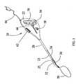
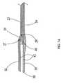
- the resecting device 10is comprised of a shaft 20 affixed to a handle 22 having a jaw trigger 70.
- the jaw trigger 70works in conjunction with a spring mechanism 60, shown in FIGS. 2 and 2A , to manipulate the position of the second jaw member 32 relative to the first jaw member 30.
- the jaw members 30, 32may be used to grip tissue.
- the resecting device 10may be fashioned with a spring loaded jaw trigger lock (not shown) to lock the position of the jaw trigger 70, and thereby lock the position of the jaw members 30, 32 relative to one another.
- a multi-position electrode selector 62is mounted to the handle 22 in this embodiment.
- the handle 22may be constructed of any material suitable for the particular application, which material is known to those skilled in the art, such as high-density polyethylene, aluminum, polyester, or other suitable material.
- the handle 22is composed of a material that is transparent or semi-transparent, and an illumination source is positioned within the handle 22 to illuminate the handle 22 for ease of use.
- the handle 22could be made of a material already disclosed in prior art that glows after exposure to light.
- the arrangement of the handle 22comprises one type of handle means as recited in the claims.
- the handle 22is fashioned as two pieces of approximately equal width.
- Various elements within the handle 22may be hermetically sealed in any specific embodiment.
- the handle 22may be fashioned so that each element is hermitically and electronically shielded from other elements as well as the environment external to the handle 22.
- the portion of the handle 22 that houses the electric motor 51may be fashioned so that the electric motor 51 is sealed from air, water, and/or electronic interference from other portions of the resecting device 10 and/or other such elements external to the resecting device 10.
- Any portion of the handle 22may be fashioned to provide similar sealing for the element or elements arranged within that portion of the handle 22, and the elements of the resecting device 10 that are positioned within a sealed portion of the handle 22 will vary depending on the specific embodiment.
- the shaft 20 and a portion of the handle 22 in the exemplary embodiment shown in FIGS. 1 , 1A , 2 , 2A , 7 , 7A , 9 , 10 , 10A , and 10Bencloses the bipolar cutting blade 40 and the bipolar wire loop 50 when the wire loop 50 and blade 40 are in the retracted positions.
- the shaft 20 of the resecting device 10may be comprised of a heat stable polymer or other suitable material known to those skilled in the art, such as aluminum, metal, or an alloy thereof.
- the shaft 20could be formed of a plurality of materials. It may also be formed in different configurations rather than as one single piece.
- the shaft 20could be formed of an interior material that provides thermal and electrical insulation positioned within a shell made of a different material.
- the shaft 20is formed of two portions; a slidable shaft portion 23 and a fixed shaft portion 24.
- the slidable shaft portion 23slides in the axial direction relative to the fixed shaft portion 24.
- the second jaw member 32is attached to the slidable shaft portion 23, which facilitates actuation of the second jaw member 32 in this embodiment.
- jaw members 30 and 32are one type of gripping means as recited in the claims.
- FIG. 2A detailed view of one embodiment of the internal elements of the handle 22 showing the jaw trigger 70 and the spring mechanism 60 is shown in FIG. 2 .
- FIG. 2AA cross-sectional view of the same embodiment of the handle 22 is shown in FIG. 2A .
- the handle 22 in the exemplary embodimentis designed so that the resecting device 10 may be used by either the right or left hand of the user without need to adjust the resecting device 10.
- Other shapes and embodiments of the handle 22will be obvious to those skilled in the art, and variations to the embodiments described and disclosed herein will occur without departure from the spirit and scope of the present invention.
- the jaw trigger 70moves away from the shaft 20 in an axial direction with respect to the shaft 20, and the jaw trigger beam engagers 74, which communicate to the beams 76 mechanical forces imparted to the jaw trigger 70, move in that same direction.
- the translator 78is fashioned as a disk oriented so that the shaft 20 and the disk share a similar axis.
- the translator 78is connected to the slidable shaft portion 23 through the translator connector 13, so that the slidable shaft portion 23, translator 78, and translator connector 13 may be formed as one piece.
- the spring mechanism 60biases the translator 78 in an axial direction away from the shaft 20, which biases the slidable shaft portion 23 in the same direction, thereby separating the jaw members 30, 32 unless an external force is applied to the jaw trigger 70.
- the beams 76cause the translator 78 to work against the force of the spring mechanism 60, and when the force imparted from the beams 76 to the translator 78 overcomes the spring force of the spring mechanism 60, the translator 78 will cause the slidable shaft portion 23 to slide relative to the fixed shaft portion 24 in an axial direction away from the handle 22, subsequently causing the second jaw member 32 to move towards the first jaw member 30.
- the arrangement of the beams 76, jaw trigger beam engagers 74, jaw trigger 70, translator connector 13, translator 78, and jaw members 30, 32 in the embodiment shown in FIGS. 1-2Aallow a small amount of travel in the second jaw member 32 to correspond to a larger amount of travel in the jaw trigger 70. That is, the length and orientation of the beams 76, and the manner in which the beams 76 engage the translator 78 cause a specific magnitude of travel (2 millimeters for example) in the jaw member to effect a corresponding but unequal, smaller magnitude of travel in the second jaw member 32 (0.2 millimeters for example).
- the translation of magnitude of travel from the jaw trigger 70 to the magnitude of travel of the second jaw member 32also allows the user to transfer more force to the second jaw member 32 at a given force applied to the jaw trigger 70, as is known to those skilled in the art.
- the specific ratio between jaw trigger 70 travel and the corresponding second jaw member 32 travelmay be adjusted for the specific application of the resecting device 10, and therefore, the specific embodiment or ratio achieved thereby in no way limit the scope of the present invention.
- the arrangement of the jaw trigger 70, beams 76, jaw trigger beam engagers 74, translator connector 13, and translator 78are one actuating means as recited in the claims.
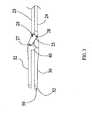
- FIGS. 3-3BA detailed view of one embodiment of the first jaw member 30 and second jaw member 32 is shown in FIGS. 3-3B .
- a link 25serves to communicate forces from the slidable shaft portion 23 to the second jaw member 32 and vice versa.
- the spring mechanism 60applies a force that causes the first jaw member 30 to be separated from the second jaw member 32 (i.e., the position shown in FIG. 3 ) unless a user actuates the jaw trigger 70.
- the second jaw member 32(with the associated linkage) cooperates with the first jaw member 30 to form a set of cantilevered jaws.
- the link 25moves from the position shown in FIG. 3 to the position shown in FIG. 3A .
- the link 25pivots about the second jaw member/link connector 27, slidable shaft portion/link connector 29, and fixed shaft portion/link connector 28.
- the pin 26, pin cap 38(which functions to secure a pin 26 within pin apertures 36) and associated pin apertures 36 in the link 25 and second jaw member 32 (all of which are best shown in FIG. 10B ) make up the second jaw member/link connector 27, which mechanically connects the second jaw member 32 to the link 25.
- FIG. 10Bbest shows the pins 26, pin caps 38, and pin apertures 36 of each of the above-mentioned elements and their relation to one another.
- FIG. 3Bprovides a cross-sectional view perpendicular to the axis of the shaft 20 of the link 25, and shows the portion of the link 25 on which the knobs 21 may be located.
- FIGS. 4 and 4AA detailed view of an alternative embodiment of the first jaw member 30 and second jaw member 32 is shown in FIGS. 4 and 4A .
- a slidable sleeve 12is slidably engaged with the shaft 20 in an axial direction with respect to the shaft 20.
- the shaft 20is comprised of one portion rather than two portions (as was described for the structure in the previous embodiment having a slidable shaft portion 23 and a fixed shaft portion 24).
- the second jaw member/link connector 27is similar to the second jaw member/link connector 27 in the embodiment shown in FIGS. 3-3B , although the associated pins 26, pin caps 38, and pin apertures 36 are not separately shown for the embodiment depicted in FIGS. 4 and 4A .
- a portion of the link 25is within the interior of the shaft 20.
- the area within the dashed portion of FIG. 4represents an internal portion of the shaft 20.
- a link groove 15 formed in the shaft 20slidably engages the end of the link 25 opposite the second jaw member/link connector 27 and accounts for difference in the axial length displaced by the link 25 when the second jaw member 32 is actuated from the position shown in FIG. 4 to the position shown in FIG. 4A .
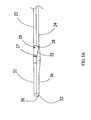
- FIGS. 5 and 5AA detailed view of an alternative embodiment of the first jaw member 30 and second jaw member 32 is shown in FIGS. 5 and 5A .
- This embodimentis similar to the embodiment shown in FIGS. 3-3B , wherein the shaft 20 is formed of a slidable shaft portion 23 and a fixed shaft portion 24.
- the embodiment in FIGS. 5 and 5Auses a second link 16 connected to both the first jaw member 30 and second jaw member 32 in any convenient manner known to those skilled in the art, such as through the use of pins 26 and pin caps 38 in conjunction with pin apertures 36.
- the second link 16ensures the second jaw member 32 does not become misaligned with respect to the first jaw member 30.
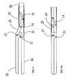
- FIGS. 6 and 6AA detailed view of yet another alternative embodiment of the first jaw member 30 and second jaw member 32 is shown in FIGS. 6 and 6A .
- both the first jaw member 30 and the second jaw member 32move during actuation of the jaw trigger 70.
- only the second jaw member 32moved during actuation of the jaw trigger 70.
- a slidable sleeve 12is slidably engaged with the shaft 20 in an axial direction with respect to the shaft 20, and the shaft 20 is comprised of one portion rather than two portions.
- a separator 18is positioned between two links 25, one of which is attached to the first jaw member 30 and the shaft 20, and another of which is attached to the second jaw member 32 and the shaft 20.
- the spring mechanism 60biases the separator 18 in an axial direction towards the handle 22, and the separator 18 acts upon each respective link 25 to urge the jaw members 30, 32 away from each other.
- the slidable sleeve 12moves along the shaft 20 towards the jaw members 30, 32 and acts upon the respective links 25 to urge the jaw members 30, 32 together.
- a pair of link grooves 15 formed in the shaft 20slidably engage the end of the links 25 opposite the second jaw member/link connector 27 and the corresponding connector on the first jaw member 30.
- the link grooves 15account for the difference in the axial length displaced by the link 25 when the jaw members 30, 32 are actuated from the position shown in FIG. 6 to the position shown in FIG. 6A .
- Two slots 31 in the first jaw member 30correspond to two knobs 21 formed in the second jaw member 30 to prevent misalignment of the jaw members 30,32 in the same manner as described for the slots 31 and knobs 21 in the embodiment shown in FIGS. 3-3B .
- first and second jaw members 30, 32 pictured in FIGS. 3-6Aallow the user to clamp more tissue between the jaw members 30, 32 in one actuation of the jaw trigger 70 than devices of the prior art are able to clamp. This advantage is realized because the distance between the jaw members 30, 32 is constant along the length of the jaw members 30, 32.
- the extreme distal portion of the jaw members 30, 32 of the present inventionare separated by the same distance as the extreme proximal portion of the jaw members 30, 32.
- Thisallows the jaw members 30, 32 to be longer when compared to devices in the prior art, so that more tissue may be clamped and electrosurgically treated by the jaw members 30, 32 in one actuation of the jaw trigger 70.
- thiswill facilitate a faster surgical procedure, increase accuracy in the tissue to be electrosurgically treated, and result in less blood loss.
- Both the first jaw member 30 and the second jaw member 32are fashioned with heavy metal contacts (not shown) that are coated with a nonstick, heat-stable material, such as Teflon or other suitable material known to those skilled in the art, to form the tissue contact areas 34 for each jaw member 30,32 (best shown in FIGS. 10-10B ).
- a source of electrosurgical energymay be connected to the metal contacts of the jaw members 30,32 (the electrosurgical energy may be routed through an electrode selector 62, as explained in detail below) via electrical conduit 44.
- Electrical conduit 44is one means of connecting the tissue contact areas 34 to a source of electrosurgical energy as recited in the claims.
- the tissue contact areas 34may serve as dual-sequencing, electrosurgical energy tissue gripping electrodes for conducting electrosurgical energy to tissues in contact with the tissue contact areas 34 of the jaw members 30, 32. That is, the tissue contact area 34 on the first jaw member 30 may serve as one electrode, and the tissue contact area 34 on the second jaw member 32 may serve as a second electrode for conducting electrosurgical energy through tissue between the jaw members 30, 32.
- the tissue contact areas 34may extend along the entire gripping surface of the jaw members 30, 32 or only a portion thereof, depending upon the specific embodiment.
- the non-stick coating on the tissue contact areas 34prevents coagulated blood or electrosurgically treated tissue from sticking to the tissue contact areas 34.
- a semiconductor chip(not shown) alternates electrosurgical energy (which may be in any frequency and amplitude that the source of electrosurgical energy is capable of delivering, including Rf frequencies) between the heavy metal contacts on the jaw members 30,32.
- the semiconductor chipwhich may be positioned within the handle 22 or in any similarly convenient location, alternates the electrosurgical energy off and on to allow maximal electrosurgical treatment of tissue with minimal lateral thermal spread; thereby ensuring a minimal amount of tissue outside the tissue contact areas 34 is affected by the electrosurgical energy. Based on tissue resistance feedback, the semiconductor chip will alternate the current.
- tissue contact areas 34may take other shapes and orientations without departing from the spirit and scope of the present invention, and the semiconductor chip may be located in any portion of the resecting device 10 that is convenient, or it may be located external from the resecting device 10, as dictated by the specific application.
- the jaw members 30, 32are curved to match the curvature of the outer wall of a human uterus, as is best shown in FIGS. 8A-8D ; although other curvatures of the jaw members 30, 32 are included within the scope of the present invention, including straight jaw members 30, 32.
- the shaft 20could be curved to facilitate a specific surgical procedure other than a hysterectomy.
- the dashed linerepresents the blade track 42 passing through the shaft 20 and the jaw members 30,32.
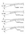
- the curvature of the jaw members 30, 32may be derived from circles having different radii, depending on the specific embodiment.
- the jaw members 30, 32may also have different angles between the straight shaft 20 portion proximate the handle 22 and the straight jaw member 30, 32 portion distal the curvature in the shaft 20 and/or jaw members 30, 32.
- this anglei.e., the angle between the straight jaw member 30,32 portion distal the curvature in the jaw members 30,32 and the straight shaft 20 portion proximate the handle 22
- Athe angle between the straight jaw member 30,32 portion distal the curvature in the jaw members 30,32 and the straight shaft 20 portion proximate the handle 22
- the linear difference between the straight shaft 20 portion and the distal end of the jaw members 30, 32is 15 millimeters. That is, the end of the jaw members 30, 32 is offset from the straight portion of the shaft 20 by 15 millimeters.
- this distancemay be adjusted as needed.
- FIG. 8Arepresents a curvature resulting from a circle having a radius of 200 millimeters.
- the embodiment shown in FIG. 8Brepresents a curvature resulting from a circle having a radius of 150 millimeters, and the embodiments in FIGS. 8C and 8D show the curvature resulting in circles having radii of 100 millimeters and 75 millimeters, respectively.
- FIGS. 8A-8Dshow the curvature resulting in circles having radii of 100 millimeters and 75 millimeters, respectively.
- the smaller the radius of the circle used to create the curvaturethe sharper and more abrupt the curvature appears.
- Variations and alterations to the curvatures and there respective lengths in the embodiments disclosed hereinwill occur to those skilled in the art without departing from the scope of the present invention.
- the blade 40operates along the blade track 42, which runs through both the slidable shaft portion 23 and fixed shaft portion 24 of the shaft 20, the link 25 (depending on the particular embodiment), and the jaw members 30, 32.
- the orientation of the blade track 42 for the exemplary embodimentis best shown in FIGS. 3B , 7A , 7B , 9 , and 10B .
- the blade 40is used to divide tissue held between the jaw members 30, 32.
- the blade 40 and blade track 42are fashioned to be such a dimension so that when the jaw members 30, 32 abut one another (as shown in FIGS.
- the blade 40may pass through the portion of the blade track 42 that extends through the jaw members 30, 32.
- the blade 40extends the entire length of the shaft 20 and is directly connected to the blade actuator 46.
- the blade 40may be mechanically engaged with an insulated blade assembly (not shown), which subsequently may be connected to the blade actuator 46.
- the blade 40(or blade assembly, depending on the particular embodiment) may also be connected to a source of electrosurgical energy, either through direct contact by an electrical conduit 44, such as wire or a conductive hub, or by a series of monopolar conductive elements (either directly or through the electrode selector 62, as explained below).
- the arrangement of the blade 40, blade track 42, blade actuator 46, and blade assembly(if present) comprise one type of mechanical resecting means as recited in the claims.
- the blade assemblymust be electrically insulated so that when the blade 40 is energized, electrosurgical energy does not flow from the blade 40 to the blade assembly, or from the blade assembly to other conductive components in the resecting device 10. If a blade assembly is not used (i.e., the blade 40 is connected directly to the blade actuator 46), the portion of the blade 40 that is enclosed in the shaft 20 must be electrically insulated, either by applying an insulating material to the outside surface of the blade 40 or by ensuring all portions of the resecting device 10 that come in contact with the blade 40 (primarily the blade track 42) are electrically insulating.
- the blade 40When energized, the blade 40 serves as one electrode and the tissue contact area 34 of the first jaw member 30, the second jaw member 32, or both serve as the corresponding electrode to create a bipolar means to deliver electrosurgical energy to tissue in contact with the blade 40.
- the position of the blade 40 along the blade track 42is determined by the position of the blade actuator 46, which is slidably engaged with the handle 22. That is, the blade actuator 46 moves relative to the handle 22, and the blade 40 (and blade assembly, depending on the embodiment) moves in the same direction and with the same magnitude.
- the limits of blade 40 travel along the blade track 42will vary depending on the specific embodiment, but typically the blade will travel at least the axial length of the tissue contact areas 34.
- the blade track 42extends to the most distal portion of the jaw members 30, 32 and the blade actuator 46 and handle 22 are configured so that the blade 40 may be extended a small distance beyond the distal end of the blade track 42 to ensure any tissue between the jaw members 30, 32 is divided upon full actuation of the blade 40.
- the wire loop 50is situated at the distal end (with respect to the handle 22) of the shaft 20, and in the exemplary embodiment protrudes from the first jaw member 30 through two wire apertures 56, which is best shown in FIGS. 10 and 10A .
- the wire loop 50a portion of which is positioned in the interior of the handle 22 in the exemplary embodiment but may be positioned elsewhere in alternative embodiments, extends through an electrically insulated conduit 59 (which is located within the shaft 20 and relevant portions of the handle) to the wire spool 53.
- the wire loop 50may be made of any suitable material that is capable of conducting electrosurgical energy and provides sufficient flexibility, such as a polymer coated ferrous metal, or any other suitable material known to those in the art that is suitable for the conditions in which the resecting device 10 will be used.
- the wire spool 53is also positioned in the interior of the handle 22 in the exemplary embodiment.
- the wire spool 53is mechanically engaged with an electric motor 51, which causes the wire spool 53 to rotate in one of two directions depending on the position of the wire loop switch 54.
- the wire loop switch 54is located exterior to the handle 22 and is easily accessible by the thumb of the user.
- the wire loop switch 54is in electrical communication with the electric motor 51, and the position of the wire loop switch 54 controls the operation of the electric motor 51.
- the electric motor 51rotates the wire spool 53 a direction that causes the wire loop 50 to deploy distally from the shaft 20, as shown in FIG. 10A .
- the electric motor 51rotates the wire spool 53 in a direction opposite to the direction it rotates when the wire loop switch 54 is in the first position, and the wire loop 50 retracts towards the distal end of the shaft 20, as shown in FIG. 10 .
- the wire loop switch 54includes a third position in which the electric motor 51 is not energized and therefore does not rotate in either direction.
- a wire loop handle 58may also be mechanically engaged with the wire spool 53 to manually retract and deploy the wire loop 50.
- the electric motor 51may be powered by a battery (not shown), or it may be powered from a typical wall outlet through the use of appropriate circuitry, as is well known to those skilled in the art (shown in FIG. 11 ).
- the wire loop 50When fully retracted, the wire loop 50 rests against the contact plate 52, which is affixed to the distal end of the first jaw member 30 in the exemplary embodiment, and is best shown in FIGS. 10 and 10A . As noted above, the wire loop 50 protrudes from the first jaw member 30 through wire apertures 56. As is well known to those skilled in the art, the contact plate 52 may be placed at other distal positions along the shaft 20 without departing from the spirit and scope of the present invention.
- the wire spool 53When fully deployed, the wire spool 53 is essentially empty of all wire and the wire loop 50 has its largest periphery, which may vary depending on the specific embodiment; when fully retracted, a larger portion of the wire is engaged with the wire spool 53 and the wire loop 50 has its smallest periphery.
- the wire loop 50may also be connected to a source of electrosurgical energy, either through direct contact by an electrical conduit 44, such as wire or a conductive hub, or through a series of mono-polar conductive elements (either directly or through the electrode selector 62, as explained below).
- the contact plate 52acts as the ground for the wire loop 50 to form a bipolar electrosurgical circuit.
- the arrangement of the wire loop 50 and wire spool 53comprise one loop means as recited in the claims.
- FIG. 11provides a simplified schematic diagram of the circuitry of one embodiment of the resecting device 10.
- the electrode selector 62is placed so that a portion of the electrode selector 62 is exterior to the handle 22 in a position easily accessible to the user. This portion of the electrode selector consists of the jaw button 66, blade button 67, and loop button 68.
- FIG. 11provides a simplified schematic diagram of how several electrodes (tissue contact areas 34, blade 40, wire loop 50) may be in communication with a source for electrosurgical energy through the electrode selector 62.
- the source for electrosurgical energyis in direct communication with a foot pedal 64 that must be depressed to allow the electrosurgical energy to travel from the source of electrosurgical energy to the electrode selector 62.
- a foot pedal 64With the foot pedal 64 depressed, a specific position of the electrode selector 62 will cause the electrode corresponding to that position to be energized with electrosurgical energy.
- the electrode selector 62will allow the tissue contact areas 34 of the jaw members 30, 32 to be energized with electrosurgical energy; if the blade button 67 is pressed, the electrode selector will allow the blade 40 to be energized with electrosurgical energy; and if the loop button 68 is pressed, the electrode selector 62 will allow the wire loop 50 to be energized with electrosurgical energy.
- the electrode selector 62is preferably a lockout style switch that allows only one element to be energized at any given time. That is, if the jaw button 66 is pressed, the electrode selector will not allow electrosurgical energy to pass to the blade 40 or the wire loop 50.
- the user interface of the electrode selector 62(the respective buttons 66, 67, and 68) may be illuminated to facilitate selection of the proper electrode in low-light environments. Illumination of the buttons 66, 67, 68 may be accomplished by placing an illuminating bulb (not shown) inside the handle 22, by making the buttons 66, 67, 68 from a material that glows after exposure to light, or by any other means known in the art.
- buttons 66, 67, 68may also be fashioned so that they are resistant to water by hermetically sealing the interface between the buttons 66, 67, 68 and the electrode selector 62, as is known in the art. This sealing may be accomplished through appropriate glue, thermoforming of plastic, or any other suitable means known to those skilled in the art.
- the buttons 66, 67, 68are fashioned of a translucent flexible material, such as silicon, polyethylene, polypropylene, or other suitable material.
- the jaw button 66is green
- the blade button 67is yellow
- the loop button 68is red, so that the user can easily distinguish among the buttons 66, 67, 68.
- the electrode selector 62would only require two positions to operate properly.
- the electrode selector 62may have multiple positions, including a first position for energizing the blade 40, a second for energizing the first jaw member 30, a third for energizing the second jaw member 32, and a fourth for energizing the wire loop 50.
- the electrode selector 62may have other positions as well, such as different positions to specify which jaw member 30, 32 serves as the ground electrode when the blade 40 is energized.
- any embodiment of the electrode selector 62in no way limit the spirit or scope of the present invention.
- the arrangement of the electrical conduit 44, wire loop 50, contact plate 52, wire spool 53, wire loop switch 54, insulated conduit 59, electrode selector 62, foot pedal 64, jaw button 66, blade button 67 and loop button 68comprise one means to connect and/or actuate the source of electrosurgical energy with the gripping means and/or loop means as recited in the claims.
- the arrangement of the electrode selector 62, foot pedal 64, jaw button 66, blade button 67 and loop button 68comprise an energy selector means as recited in the claims.
- the resecting device 10may be used in any type of surgical procedure in which the user would find the resecting device 10 convenient, and any specific method of use or surgical procedure described herein in no way limits the scope of the present invention.
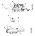
- a specialized trocar 101 shown in FIG. 12Aconstructed of any material known by those skilled in the art to be appropriate for a specific application (such as metal, polymer, composite, etc.), is outfitted with a perforated flexible introducer sheath 100 (shown in FIGS. 12B-13 ) around the outer surface of the trocar 101.
- the introducer sheath 100may be constructed of any flexible material suitable for the specific surgical procedure. In one embodiment, the introducer sheath 100 will be constructed of latex rubber having a thickness from 0.001 millimeter to 1 millimeter.
- the introducer sheath 100is fashioned with perforations 106 along the length of the introducer sheath body 110 so that it may be separated and removed from a surgical instrument at any time during the procedure.
- the perforations 106may extend along one or more axial planes for the length of the introducer sheath 100.
- the introducer sheath 100is also fashioned with an introducer sheath ring 108 on the portion of the introducer sheath 100 that is exterior to the patient.
- the introducer sheath ring 108provides the site for entry of a surgical instrument into the introducer sheath 100 and ensures the introducer sheath 100 does not slip into the incision.
- the introducer sheath ring 108also ensures that a portion of the introducer sheath 100 will remain accessible and visible if the user desires to remove the introducer sheath 100.
- the introducer sheath ring 108may be made of the same material as the introducer sheath body 110, or of another suitable material for the specific application, which material imparts sufficient rigidity to the introducer sheath ring to allow the user to easily grasp and remove the introducer sheath 100.
- the end of the introducer sheath 100 opposite the introducer sheath ring 108is closed (as shown in FIG. 12B ), but may be easily pierced with the proper tool, as described in detail below.
- the usermay simply grasp a portion of the introducer sheath ring 108 on either side of the perforations 106 and pull the respective portions up and away from the incision, causing the introducer sheath 100, including the introducer sheath body 110 and introducer sheath ring 108, to divide along the perforations 106, as shown in FIG. 13 .
- the perforations 106do not extend along the entire length of the introducer sheath 106.
- the trocar 101 and the introducer sheath 100are inserted into the abdominal cavity through the incision and path through the abdominal wall 80 created by the penetrating trocar.
- the trocar button 102When the inserted end of the trocar 101 has passed through the abdominal wall 80, the user presses the trocar button 102, which causes a stylus 104 within the trocar 101 to protrude through the inserted end of the trocar 101 and pierce the corresponding end of the introducer sheath 100, as shown in FIG. 12C .
- the trocar 101is then removed from the introducer sheath 100 and the resecting device 10 is inserted through the introducer sheath 100 into the same incision and path (as shown in FIG. 12G ) in the abdominal wall 80.
- the surgical instrumentis then positioned according to the surgical procedure to be undertaken, as shown in FIGS. 14 and 15 , which corresponds to procedures involving a hysterectomy.
- the flexible design of the introducer sheath 100accommodates the curved jaw embodiments of the resecting device 10.
- the presence of the introducer sheath 100 in the incisionmitigates the possibility of the user placing the resecting device 10 in an improper location (e.g., straying into subcutaneous, preperitoneal, or rectus muscle compartments).
- the introducer sheath 100also facilitates timely placement of the resecting device 10 in the area of the patient where the surgery is to take place.
- the introducer sheath 100is designed to be removable so that if it slips down the shaft 20 of the resecting device 10 towards the patient, the user may remove the introducer sheath 100 prior to its interference with the actuation of the jaw members 30, 32.
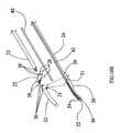
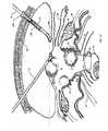
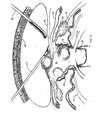
- the resecting device 10is placed adjacent to the uterus 81 as shown in FIGS. 14 and 15 , and a grasping forcep 112 is also used.
- a grasping forcep 112is also used.
- Such positioningallows for rapid electrosurgical treatment and/or division of all tissue on one side of the uterus 81 at once, including the infundibulopelvic ligament 82 or proper ovarian ligament 83, round ligament 84, fallopian tube 85, broad ligament 86 (shown in FIGS. 18-21 ), and lateral uterine vessels 87.
- the resecting device 10also allows for easy and rapid removal of the ovaries 88 if the procedure includes salpingoophorectomy, wherein the infundibulopelvic ligament is divided, as shown in FIG. 17 .
- the curvature of the jaw members 30, 32also helps to mitigate incomplete or improper electrosurgical treatment of any portion of the uterine artery 95, which could lead to excessive bleeding.
- the curvature of the jaw members 30, 32allows the user to approach the ascending branch of the uterine artery (the portion of the uterine artery 95 that is shown as following the outer wall of the uterus in FIGS.
- the shape and dimension of the jaw members 30,32mitigates the possibility of damage to other surrounding tissues, such as the bladder 90, uterosacral ligament 91, ovaries 88 (depending on the procedure), rectum 96, and ureter 94.
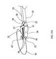
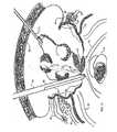
- FIG. 18shows the resecting device positioned to treat the proper tissue on the contra-lateral side of the uterus 81 after the tissue on the first side has been treated.
- the anterior vesicouterine fold 92is opened by the jaw members 30, 32 and peeled off of the uterocervical junction 93.
- the userthen deploys the wire loop 50 by positioning the wire loop switch 62 in the position corresponding to deployment of the wire loop 50 (or by manually rotating the wire spool 53 with the wire loop handle 58).
- an electric motor 51 engaged with the wire spool 53 and controlled by the wire loop switch 54unwinds the wire on the wire spool 53 to extend the wire loop 50 until the wire loop 50 passes over the unattached upper portion of the uterus 81, as shown in FIG. 20 .
- the wire loop switch 54is positioned so that the electric motor 51 and wire spool 53 are reversed; thereby retracting the wire loop 50 tightly against the cervix 89.
- the electrode selector 62is set to the position that energizes the wire loop 50 by pressing the loop button 68, and the combination of the wire loop 50 retraction around the uterocervical junction 93 with energizing the wire loop 50, which is grounded through the contact plate 52 to form a bipolar electrosurgical delivery means, will hemostatically amputate the cervix in seconds.
- the completely unattached uterus 81may be endoscopically removed with a morcellator, or through other appropriate means known to those skilled in the art.
- the resecting device 10is not limited by the specific surgical procedure for which it is adapted and/or used, but includes any endoscopic or laparoscopic procedure, as well as any open surgery. Therefore, any references to anatomical structures and/or tissues for which the resecting device 10 may be useful in electrosurgically treating, resecting, or dividing are meant to be illustrative examples only, and in no way limit the scope of the present invention. Accordingly, the resecting device 10 and the curvature of any portions thereof may vary within the scope of the present invention.
Landscapes
- Health & Medical Sciences (AREA)
- Surgery (AREA)
- Engineering & Computer Science (AREA)
- Life Sciences & Earth Sciences (AREA)
- Biomedical Technology (AREA)
- Otolaryngology (AREA)
- Nuclear Medicine, Radiotherapy & Molecular Imaging (AREA)
- Plasma & Fusion (AREA)
- Physics & Mathematics (AREA)
- Heart & Thoracic Surgery (AREA)
- Medical Informatics (AREA)
- Molecular Biology (AREA)
- Animal Behavior & Ethology (AREA)
- General Health & Medical Sciences (AREA)
- Public Health (AREA)
- Veterinary Medicine (AREA)
- Surgical Instruments (AREA)
Description
- This invention relates to a surgical instrument and, more specifically, to a multi-polar electrosurgical resecting device.
- Each year, approximately 600,000 hysterectomy procedures are performed in the Untied States, totaling more than 5 billion dollars in medical expenses. Many different surgical methods are available for performing a hysterectomy, and the degree of intrusiveness and recovery time are dependent on the surgical method chosen. Typically, for non-endoscopic hysterectomies, the recovery time is approximately six weeks. As technology has progressed, there has been a movement for quicker, safer methods for performing hysterectomies.
- Electrosurgical forceps, such as those disclosed in
U.S. Patent No. 7,232,440 , utilize both mechanical action and electrosurgical energy to treat tissue. In electrosurgery, electricity alternates current through tissue held between two electrodes. The frequency at which the current alternates should generally be set at 100,000 cycles per second (often referred to as "radio" frequencies) or above. In bipolar electrosurgery, both the positive and ground electrodes are located at the site of surgery (e.g., a forceps wherein one lead is the positive electrode of a circuit and the other lead is the negative electrode of that circuit). In monopolar electrosurgery only the active electrode is in the wound, and the ground electrode is at another location on the patient's body. - The effect of the electrosurgical energy on tissue depends on the waveform of the electrosurgical energy. As is well known to those skilled in the art, the waveform may be manipulated to cut or vaporize tissue, coagulate tissue, or a mixture of both. Tissue dessication occurs when the electrode is in direct contact with the tissue, which may be achieved using several different waveforms.
- The CDC has reported a significant increase in the proportion of laparoscopic assisted vaginal hysterectomies (LAVH) over the past decade. In a 1994 study comparing LAVH patients with patients undergoing total abdominal hysterectomies (TAH), it was shown that LAVH patients undergo longer surgical operations and more costly hospital stays, but they also stay in the hospital for significantly less time, have less pain during recovery, and are able to engage in significantly more postoperative activity sooner. Results from a 1997 study comparing patients undergoing LAVH to patients undergoing vaginal hysterectomies showed that although LAVH patients underwent longer, more costly surgery, there was significantly less blood loss associated with the LAVH procedures.
- Numerous patents exist for surgical devices designed for endoscopic cholecystectomy; however, there are currently no dedicated devices for endoscopic pelvic surgery. Specifically,
U.S. Pat. No. 4,493,320 shows a bipolar electrosurgical cautery snare;U.S. Pat. No. 5,569,244 shows loop electrodes for electrocautery for probes for use with a resectoscope; andU.S. Pat. No. 5,458,598 shows tripolar cutting forceps. The endoscopic cholecystectomy devices now in use are generally very slow, with small cutting/cauterizing areas requiring very high amounts of electricity and high temperatures, which can damage surrounding tissue and result in more time-consuming surgical procedures. - Further relevant prior art is disclosed by
US 2002/0013583 A1 ,US 2006/0084974 A1 ,US 2006/0069388 A1 andUS 2002/0111624 A1 . - The invention is defined by
claim 1. Preferred embodiments are defined by the dependent claims. Further embodiments disclosed herein do not form part of the invention and are for exemplary purpose only. - Certain embodiments of the resecting device pictured and described herein are exclusively and uniquely designed for a laparoscopic supracervical hysterectomy, total laparoscopic hysterectomy, laparoscopic assisted vaginal hysterectomy, total abdominal hysterectomy, and/or total abdominal supracervical hysterectomy procedure with or without salpingoophorectomy. In these embodiments, the resecting device is used during endoscopic pelvic surgery to rapidly electrosurgically treat the abundant blood supply and the tissue of the infudibulopelvic ligament, proper ovarian ligament, round ligament, fallopian tubes, broad ligament, lateral uterine vessels, and open the vesicouterine fold. The resecting device may also be used to divide the appropriate anatomical structures subsequent to or simultaneously with treatment via electrosurgical energy, and the division of tissue may be aided through treatment of the tissue with electrosurgical energy. These anatomical structures should be electrosurgically treated and divided in thirty to sixty seconds per side and the cervix should be hemostatically amputated within two to three seconds, when necessary according to the specific procedure. Utilizing the resecting device alone it is anticipated to be the fastest uterine resector of any prior art (three to five minutes). In other embodiments, the resecting device is used for other types of endoscopic or laparoscopic surgery, such as a nephrectomy or splenectomy. Other alternative embodiments may be used with open surgical procedures. Accordingly, the scope of the present invention is not limited by the specific method of use of the resecting device or the surgical procedure for which a specific embodiment of the resecting device is designed.
FIG. 1 is a perspective view of a first embodiment of the present invention.FIG. 1A is another perspective view of the first embodiment of the present invention.FIG. 2 is a detailed view of the internal portions of the handle of the first embodiment.FIG. 2A is a detailed, cutaway view of the handle of the first embodiment.FIG. 3 is a detailed view of the first embodiment of the jaw members.FIG. 3A is another detailed view of the first embodiment of the jaw members.FIG. 3B is a cross-sectional view of the link and the jaw members in the first embodiment of the jaw members.FIG. 4 is a detailed view of a second embodiment of the jaw members in an open position.FIG. 4A is a detailed view of the second embodiment of the jaw members in a closed position.FIG. 5 is a detailed view of a third embodiment of the jaw members in an open position.FIG. 5A is a detailed view of the third embodiment of the jaw members in a closed position.FIG. 6 is a detailed view of a fourth embodiment of the jaw members in an open position.FIG. 6A is a detailed view of the fourth embodiment of the jaw members in a closed position.FIG. 7 is a cross-sectional view along the shaft of the first embodiment of the first and second jaw members in a closed position.FIG. 7A is a cross-sectional view along the shaft of the first embodiment of the first and second jaw members in an open position.FIG. 8A is a dimensional view of a first embodiment of the curvature of the jaw members.FIG. 8B is a dimensional view of a second embodiment of the curvature of the jaw members.FIG. 8C is a dimensional view of a third embodiment of the curvature of the jaw members.FIG. 8D is a dimensional view of a fourth embodiment of the curvature of the jaw members.FIG. 9 is a cross-sectional view of the shaft of the first embodiment.FIG. 10 is a perspective view detailing the jaw members of the first embodiment with the wire loop retracted.FIG. 10A is another perspective view detailing the jaw members of the first embodiment with the wire loop deployed.FIG. 10B is an exploded view of the jaw members of the first embodiment.FIG. 11 is a schematic diagram of the electrosurgical energy paths in one embodiment of the resecting device.FIG. 12A is a detailed view of one embodiment of the trocar not engaged with the introducer sheath.FIG. 12B is a detailed view of the trocar engaged with the introducer sheath being inserted into the abdominal wall.FIG. 12C is a detailed view of one embodiment of the trocar engaged with the introducer sheath after the trocar button has been pushed to pierce the introducer sheath.FIG. 12D is a detailed view of the introducer sheath engaged with the trocar showing how the trocar is removed from the introducer sheath.FIG. 12E is a detailed view of the introducer sheath passing through the abdominal wall after the trocar has been removed.FIG. 12F is a detailed view of the top of the introducer sheath showing the introducer sheath ring.FIG. 12G is a detailed view of the resecting device being inserted through the abdominal wall through the introducer sheath.FIG. 13 is a detailed view of the introducer sheath engaged with the resecting device showing the introducer sheath being separated along the perforations.FIG. 14 is a detailed view of one embodiment of the resecting device positioned within a human abdomen.FIG. 15 is another detailed view of one embodiment of the resecting device positioned within a human abdomen.FIG. 16 is a detailed view of one embodiment of the resecting device with the jaw members engaging the tissue on one side of a human uterus.FIG. 17 is a detailed view of one embodiment of the resecting device with the jaw members engaging the tissue on one side of a human uterus wherein the procedure includes salpingoophorectomy.FIG. 18 is a detailed view of one embodiment of the resecting device with the jaw members engaging the tissue on the contra-lateral side of a human uterus.FIG. 19 is a detailed view of one embodiment of the resecting device with the jaw members engaging the anterior vesicouterine fold of a human uterus.FIG. 20 is a detailed view of one embodiment of the resecting device with the wire loop deployed over a human uterus having both sides divided.FIG. 21 is a detailed view of one embodiment of the resecting device with the wire loop being retracted to divide the uterocervical junction.- A method of use for one embodiment of the resecting device is explained herein, which method explicitly refers to various anatomical structures and procedures undertaken during a hysterectomy. The method of use may differ depending on the specific embodiment of the resecting device and/or the specific procedure undertaken. Throughout this application, "treatment of tissue by electrosurgical energy" or any variation thereof is meant to include cauterization, solidification, coagulation, dessication, division, sealing, or any other effect on tissue achieved through application of electrosurgical energy to the tissue. Accordingly, the effect of the application of electrosurgical energy to tissue will vary from one procedure or use of the resecting device to the next, and such effect is not intended to limit the present invention or the type of electrosurgical energy that may be used therewith.
Step 1. For the specific procedure explained herein, after the periumbilical laparoscope and two operating trocars are placed in the right and left lower abdominal quadrants, one trocar is removed and replaced by a specialized trocar outfitted with the introducer sheath assembly (seeFIGS. 12A-12D ).- Step 2. The trocar button on the specialized trocar is depressed to cause the stylus to pierce the distal end of the introducer sheath and the trocar is removed from the introducer sheath. The resecting device is then inserted into the sheath (
FIG. 12G ). Since the jaw members of the resecting device in this embodiment are designed with a curve, the flexibility of the introducer sheath allows placement of the resecting device into the abdominal cavity without straying into subcutaneous, preperitoneal, or rectus muscle compartments. The specialized trocar and introducer sheath are particularly useful for use with obese patients because the abdominal wall of obese patients may be considerably thicker than the abdominal wall of non-obese patients. Once the resecting device is positioned in the abdomen, the introducer sheath may be pulled up and away from the shaft of the resecting device and discarded (seeFIG 13 ). - Step 3. The jaw members are allowed to open (
FIG. 15 ), as in the normal state of the resecting device. The resecting device is positioned over the pelvic anatomy to be electrosurgically treated and the user squeezes the jaw trigger so that the anatomy to be electrosurgically treated comes into contact with the tissue contact areas of the jaw members (FIGS. 16 and18 ). If the resecting device is outfitted with a jaw trigger lock, the lock may be engaged at this time. The user presses the jaw energizing button of the electrode selector so that the electrode selector directs electrosurgical energy to the heavy metal contacts in the jaw members. The foot pedal is depressed to activate the electrosurgical energy to electrosurgically treat the tissue held between the jaw members. - Step 4. The user presses the blade energizing button of the electrode selector to select the bipolar blade (which utilizes the jaw member electrodes as the ground contact). The blade is advanced while activating the foot switch to electrosurgically treat blood vessels and tissues as it divides them. The handle of the resecting device is rotated 180 degrees so that the jaw members now follow the periphery of the opposite side of the pelvic structure (
FIG. 18 ) and steps 1-4 are performed on the contralateral tissues. In a hysterectomy, the curved jaw members will allow the user easy access to the pelvic tissues immediately adjacent to the uterocervical junction at the level of the vesicouterine fold. - Step 5. The anterior vesicouterine fold is undermined and clamped with the jaw members (
FIG. 19 ). The jaw energizing button is again selected, the foot switch is activated, and the tissue is electrosurgically treated. At this point, the jaw energizing button may be selected to utilize electrosurgical energy blade routed to the blade. The vesicouterine fold tissue is divided by the user's actuating the blade, dividing the tissue held between the jaw members. The jaw members may be used to bluntly dissect the bladder from the lower uterine segment. - Step 6. The wire loop switch is positioned so that the electric motor rotates the wire spool in a direction to deploy the wire loop. The wire loop is placed over the top of the uterus and positioned proximal the cervix near the uterocervical junction (
FIG. 20 ). The wire loop energizing button on the resecting device is selected so that the electrode selector opens the circuit from the source of electrosurgical energy to the wire loop. The wire loop switch is positioned so that the electric motor rotates the wire spool in a direction to retract the wire loop. When the wire is tight against the cervix the foot switch is activated, energizing the wire loop with electrosurgical energy. The wire loop and contact plate on the distal end of the resecting device shaft complete the circuit causing the loop wire to electrosurgically treat the tissue at the uterocervical junction in contact with the wire loop. At this point, the wire loop may be retracted further to divide the tissue in contact with the wire loop (FIG. 21 ). - Step 7. The resected pelvic structures are removed using a morcellator. The abdomen is deflated, the instruments are removed, the incisions are closed, and wound dressings are placed.
- After analyzing the weaknesses of each prior art surgical device, especially those used in laparoscopic or endoscopic procedures, there are several major features of this resecting device that will dramatically decrease surgical operating time, improve safety and consistency, and increase convenience.
- In one embodiment, the jaw application site is curved to accommodate the specific pelvic vascular architecture according to the procedure to be performed (
FIGS. 8A-D ). Specifically, the jaw members may be angled to emulate the outer curvature of a human uterus. The cantilevered jaw member arrangement allows for more tissue to be held between the jaw members without the need to increase vertical clearance at the distal ends of the jaw members (i.e., there is no scissoring effect). - Teflon-coated, heavy metal contacts may be fused to a rigid, heat-stable polymer body to form tissue contact areas for delivering electrosurgical energy to tissue. This also allows the jaw members to resist heat deformation and allow the user to apply pressure during electrosurgical tissue treatment. Additionally, the jaw members may be up to sixteen centimeters long, and therefore provide the largest endoscopic electrosurgical energy delivery surface available; which allows for an extremely rapid cutting speed with precise anatomic placement (
FIGS. 16 and18 ). The Teflon coating prevents electrosurgically treated tissue from sticking to the tissue contact areas following energizing of the jaw members. A semiconductor chip may be used to alternate the electrosurgical energy between the tissue contact areas on the first and second jaw members; which facilitates cooling of tissues to limit lateral thermal damage and enhance electrosurgical treatment. - The unique electrode selector, which prevents electrosurgical energy flow to any electrode other than that selected by the user, adds safety by avoiding inadvertent energy discharge from an electrode other than the one desired by the user. As shown in
FIGS. 16 and18 , one entire side of the uterus is treated at once in most cases. - In one embodiment, an insulated rod is soldered onto the unique blade assembly (in the embodiments pictured herein, a blade assembly is not used). An electrical conduit attaches to the blade and/or blade assembly within the handle to provide a conduit for electrosurgical energy. As the blade travels forward along the blade track, the electrode selector may be positioned so that bipolar electrosurgical energy treats tissue in contact with the blade.
- The handle of the resecting device, which is ambidextrous, may be rotated 180 degrees to effectively treat both sides of pelvic structures and to facilitate easy deployment of the wire loop. The unique wire loop (if present for that particular embodiment) may be deployed by moving the wire loop switch to the appropriate position. A motorized spool unwinds the wire loop, which is especially convenient for hysterectomy procedures because the wire loop may be deployed over the uterus. Once the loop drapes over the uterus, the user may move the wire loop switch to the appropriate position to cause the electric motor to reverse, thereby reversing the wire spool and retracting the wire loop tightly against the cervix (
FIG. 21 ). The electrode selector is positioned to allow electrosurgical energy to pass to the wire loop; which electrosurgically treats the tissue in contact with the wire loop. Retracting the wire loop while simultaneously energizing the wire loop may be used to hemostatically amputate the cervix in two to three seconds. The uterus is now completely disconnected and ready for endoscopic removal using an endoscopic morcellator (see Gynecare Morcellator). In alternative embodiment, the wire spool includes a wire spool handle so that the user may manually retract and deploy the wire loop. - Radiofrequency (Rf) energy lowers the thermal energy delivered to the tissue, decreasing excess lateral thermal damage. Usual electrosurgical devices achieve temperatures of several hundred degrees (up to 800 degrees C) and operate in the 150 to 300 watt range at up to 800 volts. The present resecting device is capable of operating in an Rf capacity in the 10-15 watt range with 80 volts to minimize lateral excess thermal tissue damage.
ELEMENT DESCRIPTION ELEMENT # Resecting Device 10 Shaft Sheath 11 Slidable Sleeve 12 Translator Connector 13 Shaft/ Link Connector 14 Link Groove 15 Second Link 16 Separator 18 Shaft 20 Knob 21 Handle 22 Slidable Shaft Portion 23 Fixed Shaft Portion 24 Link 25 Pin 26 Second Jaw Member/ Link Connector 27 Fixed Shaft Portion/ Link Connector 28 Slidable Shaft Portion/ Link Connector 29 First Jaw Member 30 Slot 31 Second Jaw Member 32 Tissue Contact Area 34 Pin Aperture 36 Pin Cap 38 Blade 40 Blade Track 42 Electrical Conduit 44 Blade Actuator 46 Wire Loop 50 Electric Motor 51 Contact Plate 52 Wire Spool 53 Wire Loop Switch 54 Wire Aperture 56 Wire Loop Handle 58 Insulated Conduit 59 Spring Mechanism 60 Electrode Selector 62 Foot Pedal 64 Jaw Button 66 Blade Button 67 Loop Button 68 Jaw Trigger 70 Jaw Trigger Beam Engager 74 Beam 76 Translator 78 Abdominal Wall 80 Uterus 81 Infundibulopelvic Ligament 82 Proper Ovarian Ligament 83 Round Ligament 84 Fallopian Tube 85 Broad Ligament 86 Lateral Uterine Vessel 87 Ovary 88 Cervix 89 Bladder 90 Uterosacral Ligament 91 Anterior Vesicouterine Fold 92 Uterocervical Junction 93 Ureter 94 Uterine Artery 95 Rectum 96 Introducer Sheath 100 Trocar 101 Trocar Button 102 Stylus 104 Perforation 106 Introducer Sheath Ring 108 Introducer Sheath Body 110 Grasping Forcep 112 - Referring now to the figures, a multi-polar
electrosurgical resecting device 10 is shown. The resectingdevice 10 is designed for use in surgical procedures, with specific embodiments pictured herein designed for laparoscopic supracervical hysterectomies, total laparoscopic hysterectomies, laparoscopic assisted vaginal hysterectomies, total abdominal hysterectomies, and/or total abdominal supracervical hysterectomies with or without salpingoophorectomy. However, the resectingdevice 10 may also be used in open surgery or other types of endoscopic or laparoscopic surgery, such as nephrectomies or splenectomies, among others. In the embodiment shown inFIG. 1 , the resectingdevice 10 is comprised of ashaft 20 affixed to ahandle 22 having ajaw trigger 70. Thejaw trigger 70 works in conjunction with aspring mechanism 60, shown inFIGS. 2 and2A , to manipulate the position of thesecond jaw member 32 relative to thefirst jaw member 30. In cooperation, thejaw members device 10 may be fashioned with a spring loaded jaw trigger lock (not shown) to lock the position of thejaw trigger 70, and thereby lock the position of thejaw members handle 22 in this embodiment is amulti-position electrode selector 62. Thehandle 22 may be constructed of any material suitable for the particular application, which material is known to those skilled in the art, such as high-density polyethylene, aluminum, polyester, or other suitable material. In an embodiment not pictured herein, thehandle 22 is composed of a material that is transparent or semi-transparent, and an illumination source is positioned within thehandle 22 to illuminate thehandle 22 for ease of use. Alternatively, thehandle 22 could be made of a material already disclosed in prior art that glows after exposure to light. The arrangement of thehandle 22 comprises one type of handle means as recited in the claims. - In the exemplary embodiment, the
handle 22 is fashioned as two pieces of approximately equal width. Various elements within thehandle 22 may be hermetically sealed in any specific embodiment. For example, if the resectingdevice 10 is equipped with amotorized wire spool 53, anelectrode selector 62 and associated buttons, and/or an internal light (not shown) for illuminating thehandle 22 and/orbuttons handle 22 may be fashioned so that each element is hermitically and electronically shielded from other elements as well as the environment external to thehandle 22. That is, the portion of thehandle 22 that houses theelectric motor 51 may be fashioned so that theelectric motor 51 is sealed from air, water, and/or electronic interference from other portions of the resectingdevice 10 and/or other such elements external to theresecting device 10. Any portion of thehandle 22 may be fashioned to provide similar sealing for the element or elements arranged within that portion of thehandle 22, and the elements of the resectingdevice 10 that are positioned within a sealed portion of thehandle 22 will vary depending on the specific embodiment. - The
shaft 20 and a portion of thehandle 22 in the exemplary embodiment shown inFIGS. 1 ,1A ,2 ,2A ,7 ,7A ,9 ,10 ,10A , and10B encloses thebipolar cutting blade 40 and thebipolar wire loop 50 when thewire loop 50 andblade 40 are in the retracted positions. Theshaft 20 of the resectingdevice 10 may be comprised of a heat stable polymer or other suitable material known to those skilled in the art, such as aluminum, metal, or an alloy thereof. Alternatively, theshaft 20 could be formed of a plurality of materials. It may also be formed in different configurations rather than as one single piece. For example, theshaft 20 could be formed of an interior material that provides thermal and electrical insulation positioned within a shell made of a different material. In the exemplary embodiment, theshaft 20 is formed of two portions; aslidable shaft portion 23 and a fixedshaft portion 24. Theslidable shaft portion 23 slides in the axial direction relative to the fixedshaft portion 24. Thesecond jaw member 32 is attached to theslidable shaft portion 23, which facilitates actuation of thesecond jaw member 32 in this embodiment. In the embodiment shown inFIGS. 1 ,1A ,2 ,2A , and10 , an axial portion of theshaft 20 is enclosed in ashaft sheath 11 radially encompassing a portion of both theslidable shaft portion 23 and fixedshaft portion 24 to prevent theslidable shaft portion 23 or the fixedshaft portion 24 from buckling when thejaw trigger 70 is actuated.Jaw members - A detailed view of one embodiment of the internal elements of the
handle 22 showing thejaw trigger 70 and thespring mechanism 60 is shown inFIG. 2 . A cross-sectional view of the same embodiment of thehandle 22 is shown inFIG. 2A . Thehandle 22 in the exemplary embodiment is designed so that the resectingdevice 10 may be used by either the right or left hand of the user without need to adjust theresecting device 10. Other shapes and embodiments of thehandle 22 will be obvious to those skilled in the art, and variations to the embodiments described and disclosed herein will occur without departure from the spirit and scope of the present invention. As thehandle 22 is squeezed, thejaw trigger 70 moves away from theshaft 20 in an axial direction with respect to theshaft 20, and the jawtrigger beam engagers 74, which communicate to thebeams 76 mechanical forces imparted to thejaw trigger 70, move in that same direction. This causes thebeams 76, which are pivotally engaged to one another, to impart a force to thetranslator 78, which is mechanically engaged with theslidable shaft portion 23 through thetranslator connector 13. In this embodiment, thetranslator 78 is fashioned as a disk oriented so that theshaft 20 and the disk share a similar axis. Thetranslator 78 is connected to theslidable shaft portion 23 through thetranslator connector 13, so that theslidable shaft portion 23,translator 78, andtranslator connector 13 may be formed as one piece. Thespring mechanism 60 biases thetranslator 78 in an axial direction away from theshaft 20, which biases theslidable shaft portion 23 in the same direction, thereby separating thejaw members jaw trigger 70. As thehandle 22 is squeezed by the user and thejaw trigger 70 depressed, thebeams 76 cause thetranslator 78 to work against the force of thespring mechanism 60, and when the force imparted from thebeams 76 to thetranslator 78 overcomes the spring force of thespring mechanism 60, thetranslator 78 will cause theslidable shaft portion 23 to slide relative to the fixedshaft portion 24 in an axial direction away from thehandle 22, subsequently causing thesecond jaw member 32 to move towards thefirst jaw member 30. - The arrangement of the
beams 76, jawtrigger beam engagers 74,jaw trigger 70,translator connector 13,translator 78, andjaw members FIGS. 1-2A allow a small amount of travel in thesecond jaw member 32 to correspond to a larger amount of travel in thejaw trigger 70. That is, the length and orientation of thebeams 76, and the manner in which thebeams 76 engage thetranslator 78 cause a specific magnitude of travel (2 millimeters for example) in the jaw member to effect a corresponding but unequal, smaller magnitude of travel in the second jaw member 32 (0.2 millimeters for example). The translation of magnitude of travel from thejaw trigger 70 to the magnitude of travel of thesecond jaw member 32 also allows the user to transfer more force to thesecond jaw member 32 at a given force applied to thejaw trigger 70, as is known to those skilled in the art. The specific ratio betweenjaw trigger 70 travel and the correspondingsecond jaw member 32 travel may be adjusted for the specific application of the resectingdevice 10, and therefore, the specific embodiment or ratio achieved thereby in no way limit the scope of the present invention. The arrangement of thejaw trigger 70, beams 76, jawtrigger beam engagers 74,translator connector 13, andtranslator 78 are one actuating means as recited in the claims. - A detailed view of one embodiment of the
first jaw member 30 andsecond jaw member 32 is shown inFIGS. 3-3B . As shown inFIG. 3 , alink 25 serves to communicate forces from theslidable shaft portion 23 to thesecond jaw member 32 and vice versa. As explained above, thespring mechanism 60 applies a force that causes thefirst jaw member 30 to be separated from the second jaw member 32 (i.e., the position shown inFIG. 3 ) unless a user actuates thejaw trigger 70. The second jaw member 32 (with the associated linkage) cooperates with thefirst jaw member 30 to form a set of cantilevered jaws. As thejaw trigger 70 is actuated, causing theslidable shaft portion 23 to move away from thehandle 22 along the axis of theshaft 20, thelink 25 moves from the position shown inFIG. 3 to the position shown inFIG. 3A . During this movement, thelink 25 pivots about the second jaw member/link connector 27, slidable shaft portion/link connector 29, and fixed shaft portion/link connector 28. Thepin 26, pin cap 38 (which functions to secure apin 26 within pin apertures 36) and associatedpin apertures 36 in thelink 25 and second jaw member 32 (all of which are best shown inFIG. 10B ) make up the second jaw member/link connector 27, which mechanically connects thesecond jaw member 32 to thelink 25. Thepin 26,pin cap 38, and associatedpin apertures 36 in thelink 25 andslidable shaft portion 23 make up the slidable shaft portion/link connector 29, which mechanically connects theslidable shaft portion 23 to thelink 25. Thepin 26,pin cap 38, and associatedpin apertures 36 in thelink 25 and fixedshaft portion 24 make up the fixed shaft portion/link connector 28, which mechanically connects the fixedshaft portion 24 to thelink 25. Alternative embodiments exist in which structures other thanpins 26, pin caps 38, and pinapertures 36 may be used to mechanically connect various moving elements of the resectingdevice 10 without departing from the scope of the present invention.FIG. 10B best shows thepins 26, pin caps 38, and pinapertures 36 of each of the above-mentioned elements and their relation to one another. To prevent thesecond jaw member 32 from becoming misaligned with respect to thefirst jaw member 30, aslot 31 is fashioned in each side of thefirst jaw member 30 with which twoknobs 21 formed on either side of the second jaw member are slidably engaged (best shown inFIG. 10B ).FIG. 3B provides a cross-sectional view perpendicular to the axis of theshaft 20 of thelink 25, and shows the portion of thelink 25 on which theknobs 21 may be located. - A detailed view of an alternative embodiment of the
first jaw member 30 andsecond jaw member 32 is shown inFIGS. 4 and 4A . In this embodiment, aslidable sleeve 12 is slidably engaged with theshaft 20 in an axial direction with respect to theshaft 20. In this embodiment, theshaft 20 is comprised of one portion rather than two portions (as was described for the structure in the previous embodiment having aslidable shaft portion 23 and a fixed shaft portion 24). The second jaw member/link connector 27 is similar to the second jaw member/link connector 27 in the embodiment shown inFIGS. 3-3B , although the associated pins 26, pin caps 38, and pinapertures 36 are not separately shown for the embodiment depicted inFIGS. 4 and 4A . In this embodiment, a portion of thelink 25 is within the interior of theshaft 20. The area within the dashed portion ofFIG. 4 represents an internal portion of theshaft 20. As thejaw trigger 70 is depressed theslidable sleeve 12 moves towards thejaw members slidable sleeve 12 acts upon thelink 25 to urge thesecond jaw member 32 towards thefirst jaw member 30. During this motion, thelink 25 pivots about the shaft/link connector 14. Twoknobs 21 on thesecond jaw member 32 corresponding to twoslots 31 in thefirst jaw member 30 in this embodiment are similar to theknobs 21 andslots 31 in the embodiment shown inFIGS. 3-3B . Theknobs 21 andslots 31 keep thesecond jaw member 32 from becoming misaligned with thefirst jaw member 30. Alink groove 15 formed in theshaft 20 slidably engages the end of thelink 25 opposite the second jaw member/link connector 27 and accounts for difference in the axial length displaced by thelink 25 when thesecond jaw member 32 is actuated from the position shown inFIG. 4 to the position shown inFIG. 4A . - A detailed view of an alternative embodiment of the
first jaw member 30 andsecond jaw member 32 is shown inFIGS. 5 and 5A . This embodiment is similar to the embodiment shown inFIGS. 3-3B , wherein theshaft 20 is formed of aslidable shaft portion 23 and a fixedshaft portion 24. However, the embodiment inFIGS. 5 and 5A uses asecond link 16 connected to both thefirst jaw member 30 andsecond jaw member 32 in any convenient manner known to those skilled in the art, such as through the use ofpins 26 and pin caps 38 in conjunction withpin apertures 36. Thesecond link 16 ensures thesecond jaw member 32 does not become misaligned with respect to thefirst jaw member 30. Therefore, twoslots 31 fashioned in thefirst jaw member 30 and two correspondingknobs 21 formed in either side of the second jaw member are not required in this embodiment. The operation of thejaw members FIGS. 3-3B ; however, the useable portion of thejaw members second link 16, as can be seen inFIGS. 5 and 5A . - A detailed view of yet another alternative embodiment of the
first jaw member 30 andsecond jaw member 32 is shown inFIGS. 6 and 6A . In this embodiment, both thefirst jaw member 30 and thesecond jaw member 32 move during actuation of thejaw trigger 70. In all previous embodiments of thejaw members second jaw member 32 moved during actuation of thejaw trigger 70. As in the embodiment shown inFIGS. 4 and 4A , aslidable sleeve 12 is slidably engaged with theshaft 20 in an axial direction with respect to theshaft 20, and theshaft 20 is comprised of one portion rather than two portions. In this embodiment, aseparator 18 is positioned between twolinks 25, one of which is attached to thefirst jaw member 30 and theshaft 20, and another of which is attached to thesecond jaw member 32 and theshaft 20. Thespring mechanism 60 biases theseparator 18 in an axial direction towards thehandle 22, and theseparator 18 acts upon eachrespective link 25 to urge thejaw members jaw trigger 70 is actuated, theslidable sleeve 12 moves along theshaft 20 towards thejaw members respective links 25 to urge thejaw members FIGS. 4 and 4A , a pair oflink grooves 15 formed in theshaft 20 slidably engage the end of thelinks 25 opposite the second jaw member/link connector 27 and the corresponding connector on thefirst jaw member 30. Thelink grooves 15 account for the difference in the axial length displaced by thelink 25 when thejaw members FIG. 6 to the position shown inFIG. 6A . Twoslots 31 in thefirst jaw member 30 correspond to twoknobs 21 formed in thesecond jaw member 30 to prevent misalignment of thejaw members slots 31 andknobs 21 in the embodiment shown inFIGS. 3-3B . - In all embodiments pictured and described herein, the default position of the
jaw members FIGS. 3 ,4 ,5 , and6 ; the position in which thejaw members second jaw members FIGS. 3-6A allow the user to clamp more tissue between thejaw members jaw trigger 70 than devices of the prior art are able to clamp. This advantage is realized because the distance between thejaw members jaw members jaw members jaw members jaw members jaw members jaw trigger 70. Among other advantages this will facilitate a faster surgical procedure, increase accuracy in the tissue to be electrosurgically treated, and result in less blood loss. - Both the
first jaw member 30 and thesecond jaw member 32 are fashioned with heavy metal contacts (not shown) that are coated with a nonstick, heat-stable material, such as Teflon or other suitable material known to those skilled in the art, to form thetissue contact areas 34 for eachjaw member 30,32 (best shown inFIGS. 10-10B ). A source of electrosurgical energy may be connected to the metal contacts of thejaw members 30,32 (the electrosurgical energy may be routed through anelectrode selector 62, as explained in detail below) viaelectrical conduit 44.Electrical conduit 44 is one means of connecting thetissue contact areas 34 to a source of electrosurgical energy as recited in the claims. Thetissue contact areas 34 may serve as dual-sequencing, electrosurgical energy tissue gripping electrodes for conducting electrosurgical energy to tissues in contact with thetissue contact areas 34 of thejaw members tissue contact area 34 on thefirst jaw member 30 may serve as one electrode, and thetissue contact area 34 on thesecond jaw member 32 may serve as a second electrode for conducting electrosurgical energy through tissue between thejaw members tissue contact areas 34 may extend along the entire gripping surface of thejaw members tissue contact areas 34 prevents coagulated blood or electrosurgically treated tissue from sticking to thetissue contact areas 34. Sticky tissue coagulum may rip fragile electrosurgically treated tissue while attempting to pull thejaw members jaw members handle 22 or in any similarly convenient location, alternates the electrosurgical energy off and on to allow maximal electrosurgical treatment of tissue with minimal lateral thermal spread; thereby ensuring a minimal amount of tissue outside thetissue contact areas 34 is affected by the electrosurgical energy. Based on tissue resistance feedback, the semiconductor chip will alternate the current. Higher power settings will cause faster current oscillation than lower power settings will cause. This alternating of electrosurgical energy will produce more even deposition of thermal energy across thetissue contact areas 34. Thetissue contact areas 34 may take other shapes and orientations without departing from the spirit and scope of the present invention, and the semiconductor chip may be located in any portion of the resectingdevice 10 that is convenient, or it may be located external from the resectingdevice 10, as dictated by the specific application. - In the exemplary embodiment of the
jaw members jaw members FIGS. 8A-8D ; although other curvatures of thejaw members straight jaw members shaft 20 could be curved to facilitate a specific surgical procedure other than a hysterectomy. ThroughoutFIGS. 8A-8D the dashed line represents theblade track 42 passing through theshaft 20 and thejaw members FIGS. 8A-8D , the curvature of thejaw members jaw members straight shaft 20 portion proximate thehandle 22 and thestraight jaw member shaft 20 and/orjaw members FIGS. 8A-8D , this angle (i.e., the angle between thestraight jaw member jaw members straight shaft 20 portion proximate the handle 22) is denoted "A," and has a value of twenty degrees. In the several embodiments shown inFIGS. 8A-8D , the linear difference between thestraight shaft 20 portion and the distal end of thejaw members jaw members shaft 20 by 15 millimeters. However, depending on the particular embodiment or the particular use to which theresecting device 10 is put, this distance may be adjusted as needed. - The embodiment shown in
FIG. 8A represents a curvature resulting from a circle having a radius of 200 millimeters. The embodiment shown inFIG. 8B represents a curvature resulting from a circle having a radius of 150 millimeters, and the embodiments inFIGS. 8C and 8D show the curvature resulting in circles having radii of 100 millimeters and 75 millimeters, respectively. As is clear fromFIGS. 8A-8D , the smaller the radius of the circle used to create the curvature, the sharper and more abrupt the curvature appears. Variations and alterations to the curvatures and there respective lengths in the embodiments disclosed herein will occur to those skilled in the art without departing from the scope of the present invention. - The
blade 40 operates along theblade track 42, which runs through both theslidable shaft portion 23 and fixedshaft portion 24 of theshaft 20, the link 25 (depending on the particular embodiment), and thejaw members blade track 42 for the exemplary embodiment is best shown inFIGS. 3B ,7A ,7B ,9 , and10B . Theblade 40 is used to divide tissue held between thejaw members blade 40 andblade track 42 are fashioned to be such a dimension so that when thejaw members FIGS. 3A ,4A ,5A , and6A ) enough clearance remains so that theblade 40 may pass through the portion of theblade track 42 that extends through thejaw members blade 40 extends the entire length of theshaft 20 and is directly connected to theblade actuator 46. In an alternative embodiment, theblade 40 may be mechanically engaged with an insulated blade assembly (not shown), which subsequently may be connected to theblade actuator 46. The blade 40 (or blade assembly, depending on the particular embodiment) may also be connected to a source of electrosurgical energy, either through direct contact by anelectrical conduit 44, such as wire or a conductive hub, or by a series of monopolar conductive elements (either directly or through theelectrode selector 62, as explained below). The arrangement of theblade 40,blade track 42,blade actuator 46, and blade assembly (if present) comprise one type of mechanical resecting means as recited in the claims. - If the particular embodiment includes a blade assembly, the blade assembly must be electrically insulated so that when the
blade 40 is energized, electrosurgical energy does not flow from theblade 40 to the blade assembly, or from the blade assembly to other conductive components in theresecting device 10. If a blade assembly is not used (i.e., theblade 40 is connected directly to the blade actuator 46), the portion of theblade 40 that is enclosed in theshaft 20 must be electrically insulated, either by applying an insulating material to the outside surface of theblade 40 or by ensuring all portions of the resectingdevice 10 that come in contact with the blade 40 (primarily the blade track 42) are electrically insulating. When energized, theblade 40 serves as one electrode and thetissue contact area 34 of thefirst jaw member 30, thesecond jaw member 32, or both serve as the corresponding electrode to create a bipolar means to deliver electrosurgical energy to tissue in contact with theblade 40. The position of theblade 40 along theblade track 42 is determined by the position of theblade actuator 46, which is slidably engaged with thehandle 22. That is, theblade actuator 46 moves relative to thehandle 22, and the blade 40 (and blade assembly, depending on the embodiment) moves in the same direction and with the same magnitude. The limits ofblade 40 travel along theblade track 42 will vary depending on the specific embodiment, but typically the blade will travel at least the axial length of thetissue contact areas 34. In other embodiments not shown herein, theblade track 42 extends to the most distal portion of thejaw members blade actuator 46 and handle 22 are configured so that theblade 40 may be extended a small distance beyond the distal end of theblade track 42 to ensure any tissue between thejaw members blade 40. - The
wire loop 50 is situated at the distal end (with respect to the handle 22) of theshaft 20, and in the exemplary embodiment protrudes from thefirst jaw member 30 through twowire apertures 56, which is best shown inFIGS. 10 and10A . Thewire loop 50, a portion of which is positioned in the interior of thehandle 22 in the exemplary embodiment but may be positioned elsewhere in alternative embodiments, extends through an electrically insulated conduit 59 (which is located within theshaft 20 and relevant portions of the handle) to thewire spool 53. Thewire loop 50 may be made of any suitable material that is capable of conducting electrosurgical energy and provides sufficient flexibility, such as a polymer coated ferrous metal, or any other suitable material known to those in the art that is suitable for the conditions in which theresecting device 10 will be used. Thewire spool 53 is also positioned in the interior of thehandle 22 in the exemplary embodiment. Thewire spool 53 is mechanically engaged with anelectric motor 51, which causes thewire spool 53 to rotate in one of two directions depending on the position of thewire loop switch 54. In the embodiment shown inFIGS. 1 and2 , thewire loop switch 54 is located exterior to thehandle 22 and is easily accessible by the thumb of the user. Thewire loop switch 54 is in electrical communication with theelectric motor 51, and the position of thewire loop switch 54 controls the operation of theelectric motor 51. In a first position of thewire loop switch 54, theelectric motor 51 rotates the wire spool 53 a direction that causes thewire loop 50 to deploy distally from theshaft 20, as shown inFIG. 10A . In a second position of thewire loop switch 54, theelectric motor 51 rotates thewire spool 53 in a direction opposite to the direction it rotates when thewire loop switch 54 is in the first position, and thewire loop 50 retracts towards the distal end of theshaft 20, as shown inFIG. 10 . Thewire loop switch 54 includes a third position in which theelectric motor 51 is not energized and therefore does not rotate in either direction. A wire loop handle 58 may also be mechanically engaged with thewire spool 53 to manually retract and deploy thewire loop 50. Theelectric motor 51 may be powered by a battery (not shown), or it may be powered from a typical wall outlet through the use of appropriate circuitry, as is well known to those skilled in the art (shown inFIG. 11 ). - When fully retracted, the
wire loop 50 rests against thecontact plate 52, which is affixed to the distal end of thefirst jaw member 30 in the exemplary embodiment, and is best shown inFIGS. 10 and10A . As noted above, thewire loop 50 protrudes from thefirst jaw member 30 throughwire apertures 56. As is well known to those skilled in the art, thecontact plate 52 may be placed at other distal positions along theshaft 20 without departing from the spirit and scope of the present invention. When fully deployed, thewire spool 53 is essentially empty of all wire and thewire loop 50 has its largest periphery, which may vary depending on the specific embodiment; when fully retracted, a larger portion of the wire is engaged with thewire spool 53 and thewire loop 50 has its smallest periphery. Thewire loop 50 may also be connected to a source of electrosurgical energy, either through direct contact by anelectrical conduit 44, such as wire or a conductive hub, or through a series of mono-polar conductive elements (either directly or through theelectrode selector 62, as explained below). When thewire loop 50 is energized, thecontact plate 52 acts as the ground for thewire loop 50 to form a bipolar electrosurgical circuit. The arrangement of thewire loop 50 andwire spool 53 comprise one loop means as recited in the claims. - In any embodiment of the resecting
device 10 in which more than one element may be energized with electrosurgical energy, anelectrode selector 62 is employed to select the elements to be energized.FIG. 11 provides a simplified schematic diagram of the circuitry of one embodiment of the resectingdevice 10. In the exemplary embodiment, theelectrode selector 62 is placed so that a portion of theelectrode selector 62 is exterior to thehandle 22 in a position easily accessible to the user. This portion of the electrode selector consists of thejaw button 66,blade button 67, andloop button 68. As noted,FIG. 11 provides a simplified schematic diagram of how several electrodes (tissue contact areas 34,blade 40, wire loop 50) may be in communication with a source for electrosurgical energy through theelectrode selector 62. In one embodiment, the source for electrosurgical energy is in direct communication with afoot pedal 64 that must be depressed to allow the electrosurgical energy to travel from the source of electrosurgical energy to theelectrode selector 62. With thefoot pedal 64 depressed, a specific position of theelectrode selector 62 will cause the electrode corresponding to that position to be energized with electrosurgical energy. If thejaw button 66 is pressed, theelectrode selector 62 will allow thetissue contact areas 34 of thejaw members blade button 67 is pressed, the electrode selector will allow theblade 40 to be energized with electrosurgical energy; and if theloop button 68 is pressed, theelectrode selector 62 will allow thewire loop 50 to be energized with electrosurgical energy. Theelectrode selector 62 is preferably a lockout style switch that allows only one element to be energized at any given time. That is, if thejaw button 66 is pressed, the electrode selector will not allow electrosurgical energy to pass to theblade 40 or thewire loop 50. The user interface of the electrode selector 62 (therespective buttons buttons handle 22, by making thebuttons buttons buttons electrode selector 62, as is known in the art. This sealing may be accomplished through appropriate glue, thermoforming of plastic, or any other suitable means known to those skilled in the art. In the exemplary embodiment, thebuttons jaw button 66 is green, theblade button 67 is yellow, and theloop button 68 is red, so that the user can easily distinguish among thebuttons - In embodiments of the resecting
device 10 in which only two elements are connected to a source of electrosurgical energy, theelectrode selector 62 would only require two positions to operate properly. In other embodiments not pictured herein, theelectrode selector 62 may have multiple positions, including a first position for energizing theblade 40, a second for energizing thefirst jaw member 30, a third for energizing thesecond jaw member 32, and a fourth for energizing thewire loop 50. Theelectrode selector 62 may have other positions as well, such as different positions to specify whichjaw member blade 40 is energized. Accordingly, the specific positions, how the positions are arranged, and combinations of positions and arrangements thereof in any embodiment of theelectrode selector 62 in no way limit the spirit or scope of the present invention. The arrangement of theelectrical conduit 44,wire loop 50,contact plate 52,wire spool 53,wire loop switch 54,insulated conduit 59,electrode selector 62,foot pedal 64,jaw button 66,blade button 67 andloop button 68 comprise one means to connect and/or actuate the source of electrosurgical energy with the gripping means and/or loop means as recited in the claims. Additionally, the arrangement of theelectrode selector 62,foot pedal 64,jaw button 66,blade button 67 andloop button 68 comprise an energy selector means as recited in the claims. - The following describes a procedure for using one embodiment of the resecting
device 10 in laparoscopic or endoscopic surgery. As previously noted, the resectingdevice 10 may be used in any type of surgical procedure in which the user would find theresecting device 10 convenient, and any specific method of use or surgical procedure described herein in no way limits the scope of the present invention. - After a penetrating trocar (not shown) has been used to provide a path through the
abdominal wall 80 into the interior of the subject of the operation, aspecialized trocar 101 shown inFIG. 12A , constructed of any material known by those skilled in the art to be appropriate for a specific application (such as metal, polymer, composite, etc.), is outfitted with a perforated flexible introducer sheath 100 (shown inFIGS. 12B-13 ) around the outer surface of thetrocar 101. Theintroducer sheath 100 may be constructed of any flexible material suitable for the specific surgical procedure. In one embodiment, theintroducer sheath 100 will be constructed of latex rubber having a thickness from 0.001 millimeter to 1 millimeter. Theintroducer sheath 100 is fashioned withperforations 106 along the length of theintroducer sheath body 110 so that it may be separated and removed from a surgical instrument at any time during the procedure. Theperforations 106 may extend along one or more axial planes for the length of theintroducer sheath 100. Theintroducer sheath 100 is also fashioned with anintroducer sheath ring 108 on the portion of theintroducer sheath 100 that is exterior to the patient. Theintroducer sheath ring 108 provides the site for entry of a surgical instrument into theintroducer sheath 100 and ensures theintroducer sheath 100 does not slip into the incision. Theintroducer sheath ring 108 also ensures that a portion of theintroducer sheath 100 will remain accessible and visible if the user desires to remove theintroducer sheath 100. Theintroducer sheath ring 108 may be made of the same material as theintroducer sheath body 110, or of another suitable material for the specific application, which material imparts sufficient rigidity to the introducer sheath ring to allow the user to easily grasp and remove theintroducer sheath 100. - The end of the
introducer sheath 100 opposite theintroducer sheath ring 108 is closed (as shown inFIG. 12B ), but may be easily pierced with the proper tool, as described in detail below. To remove theintroducer sheath 100, the user may simply grasp a portion of theintroducer sheath ring 108 on either side of theperforations 106 and pull the respective portions up and away from the incision, causing theintroducer sheath 100, including theintroducer sheath body 110 andintroducer sheath ring 108, to divide along theperforations 106, as shown inFIG. 13 . In an alternative embodiment not pictured herein, theperforations 106 do not extend along the entire length of theintroducer sheath 106. - To position the
introducer sheath 100, thetrocar 101 and theintroducer sheath 100 are inserted into the abdominal cavity through the incision and path through theabdominal wall 80 created by the penetrating trocar. When the inserted end of thetrocar 101 has passed through theabdominal wall 80, the user presses thetrocar button 102, which causes astylus 104 within thetrocar 101 to protrude through the inserted end of thetrocar 101 and pierce the corresponding end of theintroducer sheath 100, as shown inFIG. 12C . Thetrocar 101 is then removed from theintroducer sheath 100 and theresecting device 10 is inserted through theintroducer sheath 100 into the same incision and path (as shown inFIG. 12G ) in theabdominal wall 80. The surgical instrument is then positioned according to the surgical procedure to be undertaken, as shown inFIGS. 14 and15 , which corresponds to procedures involving a hysterectomy. The flexible design of theintroducer sheath 100 accommodates the curved jaw embodiments of the resectingdevice 10. The presence of theintroducer sheath 100 in the incision mitigates the possibility of the user placing the resectingdevice 10 in an improper location (e.g., straying into subcutaneous, preperitoneal, or rectus muscle compartments). Theintroducer sheath 100 also facilitates timely placement of the resectingdevice 10 in the area of the patient where the surgery is to take place. Theintroducer sheath 100 is designed to be removable so that if it slips down theshaft 20 of the resectingdevice 10 towards the patient, the user may remove theintroducer sheath 100 prior to its interference with the actuation of thejaw members - If the surgical procedure is a LAVH or laparoscopic supra-cervical hysterectomy (with or without salpingoophorectomy), the resecting
device 10 is placed adjacent to theuterus 81 as shown inFIGS. 14 and15 , and a graspingforcep 112 is also used. Such positioning allows for rapid electrosurgical treatment and/or division of all tissue on one side of theuterus 81 at once, including theinfundibulopelvic ligament 82 or properovarian ligament 83,round ligament 84,fallopian tube 85, broad ligament 86 (shown inFIGS. 18-21 ), and lateraluterine vessels 87. The resectingdevice 10 also allows for easy and rapid removal of theovaries 88 if the procedure includes salpingoophorectomy, wherein the infundibulopelvic ligament is divided, as shown inFIG. 17 . The curvature of thejaw members uterine artery 95, which could lead to excessive bleeding. The curvature of thejaw members uterine artery 95 that is shown as following the outer wall of the uterus inFIGS. 14-18 ) in a more horizontal direction than devices of the prior art, which ensures that the ascending branch of the uterine artery is completely electrosurgically treated without damaging other portions of theuterine artery 95 or lateraluterine vessels 87. At the same time, the shape and dimension of thejaw members uterosacral ligament 91, ovaries 88 (depending on the procedure),rectum 96, andureter 94. - After electrosurgical treatment and/or division of the proper tissue on the first side of the uterus 81 (which is the state shown in
FIG. 18 ), the resectingdevice 10 is rotated 180 degrees and the same procedure is followed to electrosurgically treat and/or divide the tissue on the contra-lateral side of theuterus 81, thus freeing the upper portion of theuterus 81.FIG. 18 shows the resecting device positioned to treat the proper tissue on the contra-lateral side of theuterus 81 after the tissue on the first side has been treated. Once the upper portion of theuterus 81 has been freed, theuterus 81 is connected only at the uterocervical junction 93 (shown inFIG. 19 ). - At this point, the anterior
vesicouterine fold 92 is opened by thejaw members uterocervical junction 93. The user then deploys thewire loop 50 by positioning thewire loop switch 62 in the position corresponding to deployment of the wire loop 50 (or by manually rotating thewire spool 53 with the wire loop handle 58). As explained above, when thewire loop switch 62 is positioned to deploy thewire loop 50, anelectric motor 51 engaged with thewire spool 53 and controlled by thewire loop switch 54 unwinds the wire on thewire spool 53 to extend thewire loop 50 until thewire loop 50 passes over the unattached upper portion of theuterus 81, as shown inFIG. 20 . Once thewire loop 50 drapes over theuterus 81, thewire loop switch 54 is positioned so that theelectric motor 51 andwire spool 53 are reversed; thereby retracting thewire loop 50 tightly against thecervix 89. When thewire loop 50 is securely in place around theuterus 81, theelectrode selector 62 is set to the position that energizes thewire loop 50 by pressing theloop button 68, and the combination of thewire loop 50 retraction around theuterocervical junction 93 with energizing thewire loop 50, which is grounded through thecontact plate 52 to form a bipolar electrosurgical delivery means, will hemostatically amputate the cervix in seconds. At that point, the completelyunattached uterus 81 may be endoscopically removed with a morcellator, or through other appropriate means known to those skilled in the art. - Although many of the embodiments disclosed and pictured herein are specifically adapted to certain types of hysterectomies, the resecting
device 10 is not limited by the specific surgical procedure for which it is adapted and/or used, but includes any endoscopic or laparoscopic procedure, as well as any open surgery. Therefore, any references to anatomical structures and/or tissues for which theresecting device 10 may be useful in electrosurgically treating, resecting, or dividing are meant to be illustrative examples only, and in no way limit the scope of the present invention. Accordingly, the resectingdevice 10 and the curvature of any portions thereof may vary within the scope of the present invention.
Claims (28)
- A resecting device (10) comprising:a. a handle (22) having an aperture formed therein and configured to be usable with either the left or the right hand of a person without need to adjust the position of the resecting device (100), a jaw trigger (70) slidably engaged with said handle (22) and mechanically engaged with a spring mechanism (60) communicating a biasing force to said jaw trigger (70);b. a fixed shaft portion (24) having a first and a second end, wherein said fixed shaft portion first end is affixed to said handle, wherein said fixed shaft portion second end forms a first jaw member (30) such that said first jaw member (30) is an integral and unitary with respect to said fixed shaft portion (24), and wherein said first jaw member (30) has a tissue contact area (34);c. a slidable shaft portion (23) in communication with said spring mechanism (60) and slidable relative to said fixed shaft portion (24), wherein said slidable shaft portion (23) has a first and second end, wherein said slidable shaft portion first end is mechanically engaged with said spring mechanism (60), wherein said slidable shaft portion second end is mechanically engaged with a second jaw member (32) so that said second jaw member (32) and said first jaw member (30) cooperate to form a set of cantilevered jaws, wherein said second jaw member (32) has a tissue contact area (34) oriented to face said tissue contact area (34) of said first jaw member (30), wherein said tissue contact area (34) of said first jaw member (30) is biased away from said tissue contact area (34) of said second jaw member (32) via said spring mechanism (60), and wherein the distance between said tissue contact area (34) of said first jaw member (30) and said tissue contact area (34) of said second jaw member (32) is actuated by the position of said jaw trigger (70);d. a source of electrosurgical energy adapted to connect to said jaw members (30, 32) such that said tissue contact areas (34) of said jaw members (30, 32) are capable of conducting energy through tissues held therebetween;
characterized in that ;
said jaw trigger (70) is positioned within said aperture, wherein said handle (22) and jaw trigger (70) are configured to allow at least a portion of a users fingers to be positioned within said aperture and to contact said jaw trigger (70) during activation thereof, such that upon squeezing said handle and jaw trigger, the jaw trigger moves away from the shaft (20) in an axial direction with respect to the shaft (20). - The resecting device (10) according to claim 1 wherein said first jaw member (30) and said second jaw member (32) are curved to emulate the periphery of the outer surface of a human uterus.
- The resecting device (10) according to claim 2 wherein said first and said second jaw members (30, 32) are of the same length, and wherein the length of said first and said second jaw members (30, 32) is selected to encompass substantially all the tissue on one side of the human uterus that must be electrosurgically treated in a hysterectomy.
- The resecting device (10) according to claim 2 wherein the distance between said tissue contact area (34) of said first jaw member (30) and said tissue contact area (34) of said second jaw member (32) is uniform across said jaw members (30, 32) at a particular position of said jaw trigger (70).
- The resecting device (10) according to claim 4 further comprising a blade (40), wherein said blade (40) is slidably engaged with said shaft portions (23, 24) along a blade track (42) passing through the interior of said shaft portions (23, 24), said jaw members (30, 32), and any linkage connecting said slidable shaft portion (23) to said second jaw member (34), wherein said blade (40) is mechanically engaged with a blade actuator (46), wherein said blade actuator (46) is slidably engaged with said handle (22), and wherein the position of said blade (40) with respect to said blade track (42) is dependent on the position of said blade actuator (46).
- The resecting device (10) according to claim 5 wherein said blade track (42) extends into a portion of said handle (22).
- The resecting device (10) according to claim 5 wherein said blade (40) is extendable in a direction distal to said handle (22) beyond the most distal portion, with respect to said handle (22), of said jaw members (30, 32).
- The resecting device (10) according to claim 5 wherein said source of electrosurgical energy is further adapted to also connect to said blade (40) so as to conduct energy through tissues in contact with said blade (40) and either said first jaw member (30) or said second jaw member (32).
- The resecting device (10) according to claim 8 wherein said handle (22) further comprises an electrode selector (62), said electrode selector (62) comprising:a. an interior portion mounted within said handle (22), wherein said interior portion is in communication with each electrode of said resecting device (10) that is capable of conducting electrosurgical energy, and wherein said interior portion is in communication with said source of electrosurgical energy; and,b. a exterior portion that is mounted outside of said handle (22), wherein said exterior portion provides a user interface for selecting the electrode to which said electrode selector routes electrosurgical energy.
- The resecting device (10) according to claim 9 further comprising a foot pedal (64) in communication with said electrode selector (62) and said source of electrosurgical energy, wherein said foot pedal (64) functions as a switch between said electrode selector (62) and said source of electrosurgical energy.
- The resecting device (10) according to claim 10 wherein said electrode selector (62) allows the user of the tool to energize said tissue contact area (34) on said first jaw member (30), said tissue contact area (34) on said second member (32), or said blade (40), alone or in any combination thereof.
- The resecting device (10) according to claim 1 further comprising:a. a wire spool (53) positioned within and rotatable with respect to said handle (22), wherein a wire capable of conducting electrosurgical energy is positioned around and engaged with a portion of said wire spool (53), and wherein a portion of said wire is orientated as a wire loop (50) extending through an interior portion of said fixed shaft portion (24); and,b. a wire spool handle (58) engaged with said wire spool (53), wherein said wire loop is deployable outwardly from said shaft through two wire apertures (56) fashioned in the distal end of said fixed shaft portion (24) via actuation of said wire spool handle (58) in a first direction, and wherein said wire loop (50) is retractable inwardly towards said shaft via actuation of said wire spool handle (58) in a second direction.
- The resecting device (10) according to claim 12 further comprising an electric motor (51) coupled to said wire spool (53), wherein said handle (22) further comprises a wire loop switch (54) in communication with said electric motor (51) for actuating said electric motor (51).
- The resecting device (10) according to claim 13 wherein said electric motor (51) is rotatable in a first direction and a second direction opposite said first direction, and wherein said wire loop switch (54) is operable to cause said electric motor (51) to rotate in either of said directions or to remain stationary.
- The resecting device (10) according to claim 12 wherein said fixed shaft portion (24) further comprises a contact plate (52) on said first jaw member (30) oriented distal to said handle (22), wherein said source of electrosurgical energy is further adapted to also connect to said wire loop (50) such that said loop (50) is capable of conducting energy through tissues held between said wire loop (50) and said contact plate (52).
- The resecting device (10) according to claim 15 wherein said electrode selector (62) is also in communication with said wire loop (50).
- The resecting device (10) according to claim 16 wherein said electrode selector (62) allows a user to energize said tissue contact area (34) on said first jaw member (30), said tissue contact area (34) on said second jaw member (32), said blade (40), or said wire loop (50) alone or in any combination thereof.
- The resecting device (10) according to claim 1 wherein the position of said jaw trigger (70) is lockable.
- The resecting device (10) according to claim 10 or 16 wherein said electrode selector (62) is fashioned to have a jaw button (66) energizing said tissue contact areas (34) of said jaw members (30, 32), a blade button (67) energizing said blade (40), and a loop button (68) energizing a wire loop (50), wherein only one of said positions may be selected at one time.
- The resecting device (10) according to claim 10 or 16 wherein said electrode selector (62) is illuminated.
- The resecting device (10) according to claim 1 wherein said tissue contact area (34) of said jaw members (30, 32) substantially extends the entire length of said jaw members (30, 32).
- The resecting device (10) according to claim 1 wherein at least a portion of said handle (22) is further defined as being fashioned from a transparent or semi-transparent material.
- The resecting device (10) according to claim 21 wherein said resecting device (10) further comprises a light source within said handle that may illuminate either said electrode selector (62), said handle (22), or both.
- The resecting device (10) according to claim 1 wherein at least a portion of said handle (22) is further defined as being fashioned from a material that is self-illuminating after exposure to a light source.
- The resecting device (10) according to claim 1 wherein a portion of the periphery of said slidable shaft portion (23) and said fixed shaft portion (24) are encompassed by a shaft sheath (11).
- The resecting device (10) according to claim 1 wherein said shaft portions are comprised of an interior portion and an outer portion encompassing said interior portion.
- The resecting device (10) according to claim 1 wherein said handle (22) is further defined as being ambidextrous.
- The resecting device (10) according to claim 1 wherein said handle (22) is further defined as allowing 180 degree rotation of said resecting device to effectively treat both sides of an anatomical structure.
Applications Claiming Priority (3)
| Application Number | Priority Date | Filing Date | Title |
|---|---|---|---|
| US81884706P | 2006-07-06 | 2006-07-06 | |
| US11/824,407US7488319B2 (en) | 2006-07-06 | 2007-06-29 | Resecting device |
| PCT/US2007/015319WO2008005411A2 (en) | 2006-07-06 | 2007-06-29 | Resecting device |
Publications (3)
| Publication Number | Publication Date |
|---|---|
| EP2043542A2 EP2043542A2 (en) | 2009-04-08 |
| EP2043542A4 EP2043542A4 (en) | 2010-12-22 |
| EP2043542B1true EP2043542B1 (en) | 2014-09-03 |
Family
ID=38895173
Family Applications (1)
| Application Number | Title | Priority Date | Filing Date |
|---|---|---|---|
| EP07810127.6ACeasedEP2043542B1 (en) | 2006-07-06 | 2007-06-29 | Resecting device |
Country Status (6)
| Country | Link |
|---|---|
| US (3) | US7488319B2 (en) |
| EP (1) | EP2043542B1 (en) |
| JP (1) | JP5351019B2 (en) |
| AU (1) | AU2007269696B2 (en) |
| CA (1) | CA2656611C (en) |
| WO (1) | WO2008005411A2 (en) |
Families Citing this family (218)
| Publication number | Priority date | Publication date | Assignee | Title |
|---|---|---|---|---|
| US11229472B2 (en) | 2001-06-12 | 2022-01-25 | Cilag Gmbh International | Modular battery powered handheld surgical instrument with multiple magnetic position sensors |
| US8182501B2 (en) | 2004-02-27 | 2012-05-22 | Ethicon Endo-Surgery, Inc. | Ultrasonic surgical shears and method for sealing a blood vessel using same |
| US20060079879A1 (en) | 2004-10-08 | 2006-04-13 | Faller Craig N | Actuation mechanism for use with an ultrasonic surgical instrument |
| USD624183S1 (en)* | 2005-01-02 | 2010-09-21 | Roei Medical Technologies Ltd | Resecting loop for resectoscope |
| CA2561034C (en)* | 2005-09-30 | 2014-12-09 | Sherwood Services Ag | Flexible endoscopic catheter with an end effector for coagulating and transfecting tissue |
| US20070191713A1 (en) | 2005-10-14 | 2007-08-16 | Eichmann Stephen E | Ultrasonic device for cutting and coagulating |
| US7621930B2 (en) | 2006-01-20 | 2009-11-24 | Ethicon Endo-Surgery, Inc. | Ultrasound medical instrument having a medical ultrasonic blade |
| EP2043542B1 (en)* | 2006-07-06 | 2014-09-03 | Leroy L. Yates | Resecting device |
| US8911460B2 (en) | 2007-03-22 | 2014-12-16 | Ethicon Endo-Surgery, Inc. | Ultrasonic surgical instruments |
| US8057498B2 (en) | 2007-11-30 | 2011-11-15 | Ethicon Endo-Surgery, Inc. | Ultrasonic surgical instrument blades |
| US8142461B2 (en) | 2007-03-22 | 2012-03-27 | Ethicon Endo-Surgery, Inc. | Surgical instruments |
| US20080312649A1 (en)* | 2007-06-18 | 2008-12-18 | Paul Guerra | Illuminated instrument buttons |
| US8808319B2 (en) | 2007-07-27 | 2014-08-19 | Ethicon Endo-Surgery, Inc. | Surgical instruments |
| US8523889B2 (en) | 2007-07-27 | 2013-09-03 | Ethicon Endo-Surgery, Inc. | Ultrasonic end effectors with increased active length |
| US9044261B2 (en) | 2007-07-31 | 2015-06-02 | Ethicon Endo-Surgery, Inc. | Temperature controlled ultrasonic surgical instruments |
| US8512365B2 (en) | 2007-07-31 | 2013-08-20 | Ethicon Endo-Surgery, Inc. | Surgical instruments |
| US8430898B2 (en) | 2007-07-31 | 2013-04-30 | Ethicon Endo-Surgery, Inc. | Ultrasonic surgical instruments |
| US20090157076A1 (en)* | 2007-09-12 | 2009-06-18 | Athas William L | Devices and systems for minimally invasive surgical procedures |
| US8246617B2 (en)* | 2007-09-12 | 2012-08-21 | Transenterix, Inc. | Surgical snare with electrosurgical tip and method of use |
| EP2217157A2 (en) | 2007-10-05 | 2010-08-18 | Ethicon Endo-Surgery, Inc. | Ergonomic surgical instruments |
| WO2009073577A2 (en)* | 2007-11-29 | 2009-06-11 | Surgiquest, Inc. | Surgical instruments with improved dexterity for use in minimally invasive surgical procedures |
| US10010339B2 (en) | 2007-11-30 | 2018-07-03 | Ethicon Llc | Ultrasonic surgical blades |
| US7997468B2 (en)* | 2008-05-05 | 2011-08-16 | Tyco Healthcare Group Lp | Surgical instrument with clamp |
| US9089360B2 (en) | 2008-08-06 | 2015-07-28 | Ethicon Endo-Surgery, Inc. | Devices and techniques for cutting and coagulating tissue |
| US9700339B2 (en) | 2009-05-20 | 2017-07-11 | Ethicon Endo-Surgery, Inc. | Coupling arrangements and methods for attaching tools to ultrasonic surgical instruments |
| EP3345558A1 (en) | 2009-06-25 | 2018-07-11 | University of Maryland, Baltimore | Electrosurgical element and uterine manipulator for total laparoscopic hysterectomy |
| US8663220B2 (en) | 2009-07-15 | 2014-03-04 | Ethicon Endo-Surgery, Inc. | Ultrasonic surgical instruments |
| US20120247481A1 (en)* | 2009-10-02 | 2012-10-04 | Eastern Virginia Medical School | Cervical occluder |
| US8512371B2 (en)* | 2009-10-06 | 2013-08-20 | Covidien Lp | Jaw, blade and gap manufacturing for surgical instruments with small jaws |
| US8574231B2 (en)* | 2009-10-09 | 2013-11-05 | Ethicon Endo-Surgery, Inc. | Surgical instrument for transmitting energy to tissue comprising a movable electrode or insulator |
| US10441345B2 (en) | 2009-10-09 | 2019-10-15 | Ethicon Llc | Surgical generator for ultrasonic and electrosurgical devices |
| US8747404B2 (en)* | 2009-10-09 | 2014-06-10 | Ethicon Endo-Surgery, Inc. | Surgical instrument for transmitting energy to tissue comprising non-conductive grasping portions |
| US11090104B2 (en) | 2009-10-09 | 2021-08-17 | Cilag Gmbh International | Surgical generator for ultrasonic and electrosurgical devices |
| US10172669B2 (en)* | 2009-10-09 | 2019-01-08 | Ethicon Llc | Surgical instrument comprising an energy trigger lockout |
| US9050093B2 (en) | 2009-10-09 | 2015-06-09 | Ethicon Endo-Surgery, Inc. | Surgical generator for ultrasonic and electrosurgical devices |
| US8906016B2 (en)* | 2009-10-09 | 2014-12-09 | Ethicon Endo-Surgery, Inc. | Surgical instrument for transmitting energy to tissue comprising steam control paths |
| US8939974B2 (en)* | 2009-10-09 | 2015-01-27 | Ethicon Endo-Surgery, Inc. | Surgical instrument comprising first and second drive systems actuatable by a common trigger mechanism |
| US8469981B2 (en) | 2010-02-11 | 2013-06-25 | Ethicon Endo-Surgery, Inc. | Rotatable cutting implement arrangements for ultrasonic surgical instruments |
| US8951272B2 (en) | 2010-02-11 | 2015-02-10 | Ethicon Endo-Surgery, Inc. | Seal arrangements for ultrasonically powered surgical instruments |
| US8486096B2 (en) | 2010-02-11 | 2013-07-16 | Ethicon Endo-Surgery, Inc. | Dual purpose surgical instrument for cutting and coagulating tissue |
| US9028474B2 (en) | 2010-03-25 | 2015-05-12 | Covidien Lp | Microwave surface coagulator with retractable blade |
| US8696665B2 (en) | 2010-03-26 | 2014-04-15 | Ethicon Endo-Surgery, Inc. | Surgical cutting and sealing instrument with reduced firing force |
| DE102010016291A1 (en)* | 2010-04-01 | 2011-10-06 | Erbe Elektromedizin Gmbh | Surgical instrument, in particular electrosurgical instrument |
| US8834518B2 (en) | 2010-04-12 | 2014-09-16 | Ethicon Endo-Surgery, Inc. | Electrosurgical cutting and sealing instruments with cam-actuated jaws |
| US8496682B2 (en) | 2010-04-12 | 2013-07-30 | Ethicon Endo-Surgery, Inc. | Electrosurgical cutting and sealing instruments with cam-actuated jaws |
| US8709035B2 (en) | 2010-04-12 | 2014-04-29 | Ethicon Endo-Surgery, Inc. | Electrosurgical cutting and sealing instruments with jaws having a parallel closure motion |
| US8535311B2 (en) | 2010-04-22 | 2013-09-17 | Ethicon Endo-Surgery, Inc. | Electrosurgical instrument comprising closing and firing systems |
| US8685020B2 (en) | 2010-05-17 | 2014-04-01 | Ethicon Endo-Surgery, Inc. | Surgical instruments and end effectors therefor |
| GB2480498A (en) | 2010-05-21 | 2011-11-23 | Ethicon Endo Surgery Inc | Medical device comprising RF circuitry |
| US8888776B2 (en) | 2010-06-09 | 2014-11-18 | Ethicon Endo-Surgery, Inc. | Electrosurgical instrument employing an electrode |
| US8753338B2 (en) | 2010-06-10 | 2014-06-17 | Ethicon Endo-Surgery, Inc. | Electrosurgical instrument employing a thermal management system |
| US9005199B2 (en) | 2010-06-10 | 2015-04-14 | Ethicon Endo-Surgery, Inc. | Heat management configurations for controlling heat dissipation from electrosurgical instruments |
| US8764747B2 (en) | 2010-06-10 | 2014-07-01 | Ethicon Endo-Surgery, Inc. | Electrosurgical instrument comprising sequentially activated electrodes |
| US9149324B2 (en) | 2010-07-08 | 2015-10-06 | Ethicon Endo-Surgery, Inc. | Surgical instrument comprising an articulatable end effector |
| US20120016413A1 (en) | 2010-07-14 | 2012-01-19 | Ethicon Endo-Surgery, Inc. | Surgical fastening devices comprising rivets |
| US8453906B2 (en) | 2010-07-14 | 2013-06-04 | Ethicon Endo-Surgery, Inc. | Surgical instruments with electrodes |
| US8795327B2 (en) | 2010-07-22 | 2014-08-05 | Ethicon Endo-Surgery, Inc. | Electrosurgical instrument with separate closure and cutting members |
| US8979843B2 (en) | 2010-07-23 | 2015-03-17 | Ethicon Endo-Surgery, Inc. | Electrosurgical cutting and sealing instrument |
| US8663270B2 (en)* | 2010-07-23 | 2014-03-04 | Conmed Corporation | Jaw movement mechanism and method for a surgical tool |
| US9011437B2 (en) | 2010-07-23 | 2015-04-21 | Ethicon Endo-Surgery, Inc. | Electrosurgical cutting and sealing instrument |
| US9192431B2 (en) | 2010-07-23 | 2015-11-24 | Ethicon Endo-Surgery, Inc. | Electrosurgical cutting and sealing instrument |
| US9498278B2 (en) | 2010-09-08 | 2016-11-22 | Covidien Lp | Asymmetrical electrodes for bipolar vessel sealing |
| US8979890B2 (en) | 2010-10-01 | 2015-03-17 | Ethicon Endo-Surgery, Inc. | Surgical instrument with jaw member |
| US8628529B2 (en) | 2010-10-26 | 2014-01-14 | Ethicon Endo-Surgery, Inc. | Surgical instrument with magnetic clamping force |
| US8608738B2 (en) | 2010-12-06 | 2013-12-17 | Soulor Surgical, Inc. | Apparatus for treating a portion of a reproductive system and related methods of use |
| US8715277B2 (en) | 2010-12-08 | 2014-05-06 | Ethicon Endo-Surgery, Inc. | Control of jaw compression in surgical instrument having end effector with opposing jaw members |
| JP2012239831A (en)* | 2011-05-24 | 2012-12-10 | Olympus Corp | Therapeutic treatment apparatus |
| US20130090642A1 (en)* | 2011-07-06 | 2013-04-11 | Arqos Surgical, Inc. | Laparscopic tissue morcellator systems and methods |
| US9259265B2 (en) | 2011-07-22 | 2016-02-16 | Ethicon Endo-Surgery, Llc | Surgical instruments for tensioning tissue |
| US9044243B2 (en) | 2011-08-30 | 2015-06-02 | Ethcon Endo-Surgery, Inc. | Surgical cutting and fastening device with descendible second trigger arrangement |
| US9333025B2 (en) | 2011-10-24 | 2016-05-10 | Ethicon Endo-Surgery, Llc | Battery initialization clip |
| WO2013119545A1 (en) | 2012-02-10 | 2013-08-15 | Ethicon-Endo Surgery, Inc. | Robotically controlled surgical instrument |
| US9439668B2 (en) | 2012-04-09 | 2016-09-13 | Ethicon Endo-Surgery, Llc | Switch arrangements for ultrasonic surgical instruments |
| US20140005640A1 (en) | 2012-06-28 | 2014-01-02 | Ethicon Endo-Surgery, Inc. | Surgical end effector jaw and electrode configurations |
| US20140005705A1 (en) | 2012-06-29 | 2014-01-02 | Ethicon Endo-Surgery, Inc. | Surgical instruments with articulating shafts |
| US9351754B2 (en) | 2012-06-29 | 2016-05-31 | Ethicon Endo-Surgery, Llc | Ultrasonic surgical instruments with distally positioned jaw assemblies |
| US9198714B2 (en) | 2012-06-29 | 2015-12-01 | Ethicon Endo-Surgery, Inc. | Haptic feedback devices for surgical robot |
| US20140005702A1 (en) | 2012-06-29 | 2014-01-02 | Ethicon Endo-Surgery, Inc. | Ultrasonic surgical instruments with distally positioned transducers |
| US9820768B2 (en) | 2012-06-29 | 2017-11-21 | Ethicon Llc | Ultrasonic surgical instruments with control mechanisms |
| US9326788B2 (en) | 2012-06-29 | 2016-05-03 | Ethicon Endo-Surgery, Llc | Lockout mechanism for use with robotic electrosurgical device |
| US9226767B2 (en) | 2012-06-29 | 2016-01-05 | Ethicon Endo-Surgery, Inc. | Closed feedback control for electrosurgical device |
| US9393037B2 (en) | 2012-06-29 | 2016-07-19 | Ethicon Endo-Surgery, Llc | Surgical instruments with articulating shafts |
| US9408622B2 (en) | 2012-06-29 | 2016-08-09 | Ethicon Endo-Surgery, Llc | Surgical instruments with articulating shafts |
| EP2900158B1 (en) | 2012-09-28 | 2020-04-15 | Ethicon LLC | Multi-function bi-polar forceps |
| US9549749B2 (en) | 2012-10-08 | 2017-01-24 | Covidien Lp | Surgical forceps |
| US9095367B2 (en) | 2012-10-22 | 2015-08-04 | Ethicon Endo-Surgery, Inc. | Flexible harmonic waveguides/blades for surgical instruments |
| US20140135804A1 (en) | 2012-11-15 | 2014-05-15 | Ethicon Endo-Surgery, Inc. | Ultrasonic and electrosurgical devices |
| US10226273B2 (en) | 2013-03-14 | 2019-03-12 | Ethicon Llc | Mechanical fasteners for use with surgical energy devices |
| US9295514B2 (en) | 2013-08-30 | 2016-03-29 | Ethicon Endo-Surgery, Llc | Surgical devices with close quarter articulation features |
| US9814514B2 (en) | 2013-09-13 | 2017-11-14 | Ethicon Llc | Electrosurgical (RF) medical instruments for cutting and coagulating tissue |
| US9861428B2 (en) | 2013-09-16 | 2018-01-09 | Ethicon Llc | Integrated systems for electrosurgical steam or smoke control |
| US9439716B2 (en) | 2013-10-01 | 2016-09-13 | Gyrus Acmi, Inc. | Bipolar coagulation probe and snare |
| US9089337B2 (en)* | 2013-11-07 | 2015-07-28 | Gyrus Acmi, Inc. | Electrosurgical system having grasper and snare with switchable electrode |
| US9265926B2 (en) | 2013-11-08 | 2016-02-23 | Ethicon Endo-Surgery, Llc | Electrosurgical devices |
| US9526565B2 (en) | 2013-11-08 | 2016-12-27 | Ethicon Endo-Surgery, Llc | Electrosurgical devices |
| GB2521228A (en) | 2013-12-16 | 2015-06-17 | Ethicon Endo Surgery Inc | Medical device |
| GB2521229A (en) | 2013-12-16 | 2015-06-17 | Ethicon Endo Surgery Inc | Medical device |
| US9795436B2 (en) | 2014-01-07 | 2017-10-24 | Ethicon Llc | Harvesting energy from a surgical generator |
| EP3092967A4 (en)* | 2014-01-10 | 2017-08-23 | Olympus Corporation | Vaginal wall cutting tool |
| US9408660B2 (en) | 2014-01-17 | 2016-08-09 | Ethicon Endo-Surgery, Llc | Device trigger dampening mechanism |
| US9554854B2 (en) | 2014-03-18 | 2017-01-31 | Ethicon Endo-Surgery, Llc | Detecting short circuits in electrosurgical medical devices |
| US10463421B2 (en) | 2014-03-27 | 2019-11-05 | Ethicon Llc | Two stage trigger, clamp and cut bipolar vessel sealer |
| US10092310B2 (en) | 2014-03-27 | 2018-10-09 | Ethicon Llc | Electrosurgical devices |
| US10524852B1 (en) | 2014-03-28 | 2020-01-07 | Ethicon Llc | Distal sealing end effector with spacers |
| US9737355B2 (en) | 2014-03-31 | 2017-08-22 | Ethicon Llc | Controlling impedance rise in electrosurgical medical devices |
| US9913680B2 (en) | 2014-04-15 | 2018-03-13 | Ethicon Llc | Software algorithms for electrosurgical instruments |
| US9757186B2 (en) | 2014-04-17 | 2017-09-12 | Ethicon Llc | Device status feedback for bipolar tissue spacer |
| US9700333B2 (en) | 2014-06-30 | 2017-07-11 | Ethicon Llc | Surgical instrument with variable tissue compression |
| US10285724B2 (en) | 2014-07-31 | 2019-05-14 | Ethicon Llc | Actuation mechanisms and load adjustment assemblies for surgical instruments |
| US10194976B2 (en) | 2014-08-25 | 2019-02-05 | Ethicon Llc | Lockout disabling mechanism |
| US9877776B2 (en) | 2014-08-25 | 2018-01-30 | Ethicon Llc | Simultaneous I-beam and spring driven cam jaw closure mechanism |
| US10194972B2 (en) | 2014-08-26 | 2019-02-05 | Ethicon Llc | Managing tissue treatment |
| US10639092B2 (en) | 2014-12-08 | 2020-05-05 | Ethicon Llc | Electrode configurations for surgical instruments |
| US9848937B2 (en) | 2014-12-22 | 2017-12-26 | Ethicon Llc | End effector with detectable configurations |
| US10092348B2 (en) | 2014-12-22 | 2018-10-09 | Ethicon Llc | RF tissue sealer, shear grip, trigger lock mechanism and energy activation |
| US10159524B2 (en) | 2014-12-22 | 2018-12-25 | Ethicon Llc | High power battery powered RF amplifier topology |
| US10111699B2 (en) | 2014-12-22 | 2018-10-30 | Ethicon Llc | RF tissue sealer, shear grip, trigger lock mechanism and energy activation |
| US10245095B2 (en) | 2015-02-06 | 2019-04-02 | Ethicon Llc | Electrosurgical instrument with rotation and articulation mechanisms |
| US10342602B2 (en) | 2015-03-17 | 2019-07-09 | Ethicon Llc | Managing tissue treatment |
| US10321950B2 (en) | 2015-03-17 | 2019-06-18 | Ethicon Llc | Managing tissue treatment |
| US10595929B2 (en) | 2015-03-24 | 2020-03-24 | Ethicon Llc | Surgical instruments with firing system overload protection mechanisms |
| US10314638B2 (en) | 2015-04-07 | 2019-06-11 | Ethicon Llc | Articulating radio frequency (RF) tissue seal with articulating state sensing |
| US10117702B2 (en) | 2015-04-10 | 2018-11-06 | Ethicon Llc | Surgical generator systems and related methods |
| US10130410B2 (en) | 2015-04-17 | 2018-11-20 | Ethicon Llc | Electrosurgical instrument including a cutting member decouplable from a cutting member trigger |
| US9872725B2 (en) | 2015-04-29 | 2018-01-23 | Ethicon Llc | RF tissue sealer with mode selection |
| US11020140B2 (en) | 2015-06-17 | 2021-06-01 | Cilag Gmbh International | Ultrasonic surgical blade for use with ultrasonic surgical instruments |
| US10357303B2 (en) | 2015-06-30 | 2019-07-23 | Ethicon Llc | Translatable outer tube for sealing using shielded lap chole dissector |
| US10898256B2 (en) | 2015-06-30 | 2021-01-26 | Ethicon Llc | Surgical system with user adaptable techniques based on tissue impedance |
| US11051873B2 (en) | 2015-06-30 | 2021-07-06 | Cilag Gmbh International | Surgical system with user adaptable techniques employing multiple energy modalities based on tissue parameters |
| US11141213B2 (en) | 2015-06-30 | 2021-10-12 | Cilag Gmbh International | Surgical instrument with user adaptable techniques |
| US11129669B2 (en) | 2015-06-30 | 2021-09-28 | Cilag Gmbh International | Surgical system with user adaptable techniques based on tissue type |
| US10034704B2 (en) | 2015-06-30 | 2018-07-31 | Ethicon Llc | Surgical instrument with user adaptable algorithms |
| US10154852B2 (en) | 2015-07-01 | 2018-12-18 | Ethicon Llc | Ultrasonic surgical blade with improved cutting and coagulation features |
| US10194973B2 (en) | 2015-09-30 | 2019-02-05 | Ethicon Llc | Generator for digitally generating electrical signal waveforms for electrosurgical and ultrasonic surgical instruments |
| US10595930B2 (en) | 2015-10-16 | 2020-03-24 | Ethicon Llc | Electrode wiping surgical device |
| US10959771B2 (en) | 2015-10-16 | 2021-03-30 | Ethicon Llc | Suction and irrigation sealing grasper |
| US10959806B2 (en) | 2015-12-30 | 2021-03-30 | Ethicon Llc | Energized medical device with reusable handle |
| US10179022B2 (en) | 2015-12-30 | 2019-01-15 | Ethicon Llc | Jaw position impedance limiter for electrosurgical instrument |
| US10575892B2 (en) | 2015-12-31 | 2020-03-03 | Ethicon Llc | Adapter for electrical surgical instruments |
| CN108463182B (en) | 2016-01-11 | 2020-12-22 | 捷锐士阿希迈公司(以奥林巴斯美国外科技术名义) | Clamp jaw mechanism |
| US11229471B2 (en) | 2016-01-15 | 2022-01-25 | Cilag Gmbh International | Modular battery powered handheld surgical instrument with selective application of energy based on tissue characterization |
| US10716615B2 (en) | 2016-01-15 | 2020-07-21 | Ethicon Llc | Modular battery powered handheld surgical instrument with curved end effectors having asymmetric engagement between jaw and blade |
| US12193698B2 (en) | 2016-01-15 | 2025-01-14 | Cilag Gmbh International | Method for self-diagnosing operation of a control switch in a surgical instrument system |
| US11051840B2 (en) | 2016-01-15 | 2021-07-06 | Ethicon Llc | Modular battery powered handheld surgical instrument with reusable asymmetric handle housing |
| US11129670B2 (en) | 2016-01-15 | 2021-09-28 | Cilag Gmbh International | Modular battery powered handheld surgical instrument with selective application of energy based on button displacement, intensity, or local tissue characterization |
| US10555769B2 (en) | 2016-02-22 | 2020-02-11 | Ethicon Llc | Flexible circuits for electrosurgical instrument |
| DE102016204047A1 (en)* | 2016-03-11 | 2017-09-14 | Olympus Winter & Ibe Gmbh | Resectoscope and electrode assembly for it |
| US10856934B2 (en) | 2016-04-29 | 2020-12-08 | Ethicon Llc | Electrosurgical instrument with electrically conductive gap setting and tissue engaging members |
| US10987156B2 (en) | 2016-04-29 | 2021-04-27 | Ethicon Llc | Electrosurgical instrument with electrically conductive gap setting member and electrically insulative tissue engaging members |
| US10646269B2 (en) | 2016-04-29 | 2020-05-12 | Ethicon Llc | Non-linear jaw gap for electrosurgical instruments |
| US10485607B2 (en) | 2016-04-29 | 2019-11-26 | Ethicon Llc | Jaw structure with distal closure for electrosurgical instruments |
| US10702329B2 (en) | 2016-04-29 | 2020-07-07 | Ethicon Llc | Jaw structure with distal post for electrosurgical instruments |
| US10456193B2 (en) | 2016-05-03 | 2019-10-29 | Ethicon Llc | Medical device with a bilateral jaw configuration for nerve stimulation |
| US10245064B2 (en) | 2016-07-12 | 2019-04-02 | Ethicon Llc | Ultrasonic surgical instrument with piezoelectric central lumen transducer |
| US10893883B2 (en) | 2016-07-13 | 2021-01-19 | Ethicon Llc | Ultrasonic assembly for use with ultrasonic surgical instruments |
| US10842522B2 (en) | 2016-07-15 | 2020-11-24 | Ethicon Llc | Ultrasonic surgical instruments having offset blades |
| US10376305B2 (en) | 2016-08-05 | 2019-08-13 | Ethicon Llc | Methods and systems for advanced harmonic energy |
| US10285723B2 (en) | 2016-08-09 | 2019-05-14 | Ethicon Llc | Ultrasonic surgical blade with improved heel portion |
| USD847990S1 (en) | 2016-08-16 | 2019-05-07 | Ethicon Llc | Surgical instrument |
| US10952759B2 (en) | 2016-08-25 | 2021-03-23 | Ethicon Llc | Tissue loading of a surgical instrument |
| US10736649B2 (en) | 2016-08-25 | 2020-08-11 | Ethicon Llc | Electrical and thermal connections for ultrasonic transducer |
| US10751117B2 (en) | 2016-09-23 | 2020-08-25 | Ethicon Llc | Electrosurgical instrument with fluid diverter |
| US10603064B2 (en) | 2016-11-28 | 2020-03-31 | Ethicon Llc | Ultrasonic transducer |
| US11266430B2 (en) | 2016-11-29 | 2022-03-08 | Cilag Gmbh International | End effector control and calibration |
| US11033325B2 (en) | 2017-02-16 | 2021-06-15 | Cilag Gmbh International | Electrosurgical instrument with telescoping suction port and debris cleaner |
| US10792060B2 (en) | 2017-03-14 | 2020-10-06 | Gyrus Acmi, Inc. | Instrument with a controlled jaw movement |
| US10799284B2 (en) | 2017-03-15 | 2020-10-13 | Ethicon Llc | Electrosurgical instrument with textured jaws |
| US11497546B2 (en) | 2017-03-31 | 2022-11-15 | Cilag Gmbh International | Area ratios of patterned coatings on RF electrodes to reduce sticking |
| US10603117B2 (en) | 2017-06-28 | 2020-03-31 | Ethicon Llc | Articulation state detection mechanisms |
| US10820920B2 (en) | 2017-07-05 | 2020-11-03 | Ethicon Llc | Reusable ultrasonic medical devices and methods of their use |
| US11484358B2 (en) | 2017-09-29 | 2022-11-01 | Cilag Gmbh International | Flexible electrosurgical instrument |
| US11490951B2 (en) | 2017-09-29 | 2022-11-08 | Cilag Gmbh International | Saline contact with electrodes |
| US11033323B2 (en) | 2017-09-29 | 2021-06-15 | Cilag Gmbh International | Systems and methods for managing fluid and suction in electrosurgical systems |
| US11471211B2 (en)* | 2018-10-12 | 2022-10-18 | Covidien Lp | Electrosurgical forceps |
| KR102020179B1 (en)* | 2019-04-09 | 2019-11-05 | 최보환 | Electrode for electrosurgical handpiece |
| KR102021266B1 (en)* | 2019-04-12 | 2019-09-16 | 최보환 | Electrogurgical handpiece |
| US11612445B2 (en) | 2019-06-27 | 2023-03-28 | Cilag Gmbh International | Cooperative operation of robotic arms |
| US11413102B2 (en) | 2019-06-27 | 2022-08-16 | Cilag Gmbh International | Multi-access port for surgical robotic systems |
| US11723729B2 (en) | 2019-06-27 | 2023-08-15 | Cilag Gmbh International | Robotic surgical assembly coupling safety mechanisms |
| US11376082B2 (en) | 2019-06-27 | 2022-07-05 | Cilag Gmbh International | Robotic surgical system with local sensing of functional parameters based on measurements of multiple physical inputs |
| US11547468B2 (en) | 2019-06-27 | 2023-01-10 | Cilag Gmbh International | Robotic surgical system with safety and cooperative sensing control |
| US11607278B2 (en) | 2019-06-27 | 2023-03-21 | Cilag Gmbh International | Cooperative robotic surgical systems |
| CN110811937B (en)* | 2019-11-28 | 2021-12-24 | 中国人民解放军第四军医大学 | Individualized 3D prints titanium alloy sacrum false body |
| US12343063B2 (en) | 2019-12-30 | 2025-07-01 | Cilag Gmbh International | Multi-layer clamp arm pad for enhanced versatility and performance of a surgical device |
| US12053224B2 (en) | 2019-12-30 | 2024-08-06 | Cilag Gmbh International | Variation in electrode parameters and deflectable electrode to modify energy density and tissue interaction |
| US12076006B2 (en) | 2019-12-30 | 2024-09-03 | Cilag Gmbh International | Surgical instrument comprising an orientation detection system |
| US11452525B2 (en) | 2019-12-30 | 2022-09-27 | Cilag Gmbh International | Surgical instrument comprising an adjustment system |
| US11696776B2 (en) | 2019-12-30 | 2023-07-11 | Cilag Gmbh International | Articulatable surgical instrument |
| US12023086B2 (en) | 2019-12-30 | 2024-07-02 | Cilag Gmbh International | Electrosurgical instrument for delivering blended energy modalities to tissue |
| US20210196357A1 (en) | 2019-12-30 | 2021-07-01 | Ethicon Llc | Electrosurgical instrument with asynchronous energizing electrodes |
| US11911063B2 (en) | 2019-12-30 | 2024-02-27 | Cilag Gmbh International | Techniques for detecting ultrasonic blade to electrode contact and reducing power to ultrasonic blade |
| US12064109B2 (en) | 2019-12-30 | 2024-08-20 | Cilag Gmbh International | Surgical instrument comprising a feedback control circuit |
| US11779387B2 (en) | 2019-12-30 | 2023-10-10 | Cilag Gmbh International | Clamp arm jaw to minimize tissue sticking and improve tissue control |
| US12262937B2 (en) | 2019-12-30 | 2025-04-01 | Cilag Gmbh International | User interface for surgical instrument with combination energy modality end-effector |
| US11812957B2 (en) | 2019-12-30 | 2023-11-14 | Cilag Gmbh International | Surgical instrument comprising a signal interference resolution system |
| US11684412B2 (en) | 2019-12-30 | 2023-06-27 | Cilag Gmbh International | Surgical instrument with rotatable and articulatable surgical end effector |
| US12114912B2 (en) | 2019-12-30 | 2024-10-15 | Cilag Gmbh International | Non-biased deflectable electrode to minimize contact between ultrasonic blade and electrode |
| US12082808B2 (en) | 2019-12-30 | 2024-09-10 | Cilag Gmbh International | Surgical instrument comprising a control system responsive to software configurations |
| US11937863B2 (en) | 2019-12-30 | 2024-03-26 | Cilag Gmbh International | Deflectable electrode with variable compression bias along the length of the deflectable electrode |
| US11779329B2 (en) | 2019-12-30 | 2023-10-10 | Cilag Gmbh International | Surgical instrument comprising a flex circuit including a sensor system |
| US11944366B2 (en) | 2019-12-30 | 2024-04-02 | Cilag Gmbh International | Asymmetric segmented ultrasonic support pad for cooperative engagement with a movable RF electrode |
| US11786294B2 (en) | 2019-12-30 | 2023-10-17 | Cilag Gmbh International | Control program for modular combination energy device |
| US11986201B2 (en) | 2019-12-30 | 2024-05-21 | Cilag Gmbh International | Method for operating a surgical instrument |
| US12336747B2 (en) | 2019-12-30 | 2025-06-24 | Cilag Gmbh International | Method of operating a combination ultrasonic / bipolar RF surgical device with a combination energy modality end-effector |
| US11937866B2 (en) | 2019-12-30 | 2024-03-26 | Cilag Gmbh International | Method for an electrosurgical procedure |
| US11950797B2 (en) | 2019-12-30 | 2024-04-09 | Cilag Gmbh International | Deflectable electrode with higher distal bias relative to proximal bias |
| US11786291B2 (en) | 2019-12-30 | 2023-10-17 | Cilag Gmbh International | Deflectable support of RF energy electrode with respect to opposing ultrasonic blade |
| US20210196362A1 (en) | 2019-12-30 | 2021-07-01 | Ethicon Llc | Electrosurgical end effectors with thermally insulative and thermally conductive portions |
| US11660089B2 (en) | 2019-12-30 | 2023-05-30 | Cilag Gmbh International | Surgical instrument comprising a sensing system |
| US20210244465A1 (en)* | 2020-02-07 | 2021-08-12 | Covidien Lp | Electrosurgical instruments and systems including thermal cutting elements |
| CN111481304B (en)* | 2020-05-09 | 2024-08-09 | 南微医学科技股份有限公司 | A three-arm clamp |
| CN111956310B (en)* | 2020-08-26 | 2022-06-24 | 王中显 | A transvaginal cervical cancer hysterectomy device |
| WO2022225529A1 (en)* | 2021-04-23 | 2022-10-27 | Wake Forest University Health Sciences | Minimally invasive appendectomy device and method |
| US11974829B2 (en) | 2021-06-30 | 2024-05-07 | Cilag Gmbh International | Link-driven articulation device for a surgical device |
| US11931026B2 (en) | 2021-06-30 | 2024-03-19 | Cilag Gmbh International | Staple cartridge replacement |
| US12358136B2 (en) | 2021-06-30 | 2025-07-15 | Cilag Gmbh International | Grasping work determination and indications thereof |
| US20230081374A1 (en)* | 2021-08-25 | 2023-03-16 | Eximis Surgical Inc. | Segmentation instrument and controller |
| US11957342B2 (en) | 2021-11-01 | 2024-04-16 | Cilag Gmbh International | Devices, systems, and methods for detecting tissue and foreign objects during a surgical operation |
Family Cites Families (67)
| Publication number | Priority date | Publication date | Assignee | Title |
|---|---|---|---|---|
| US4493320A (en) | 1982-04-02 | 1985-01-15 | Treat Michael R | Bipolar electrocautery surgical snare |
| JPS59105141U (en)* | 1982-12-29 | 1984-07-14 | 日本シヤ−ウツド株式会社 | Catheter device for nasal insertion |
| US4655216A (en) | 1985-07-23 | 1987-04-07 | Alfred Tischer | Combination instrument for laparoscopical tube sterilization |
| US4917082A (en) | 1988-06-02 | 1990-04-17 | Circon Corporation | Resectoscope electrode |
| US5108406A (en)* | 1990-12-14 | 1992-04-28 | L.P. Wagi | Instrument to retrieve intraluminal objects |
| US5433725A (en)* | 1991-12-13 | 1995-07-18 | Unisurge, Inc. | Hand-held surgical device and tools for use therewith, assembly and method |
| US5254117A (en)* | 1992-03-17 | 1993-10-19 | Alton Dean Medical | Multi-functional endoscopic probe apparatus |
| US5158561A (en)* | 1992-03-23 | 1992-10-27 | Everest Medical Corporation | Monopolar polypectomy snare with coagulation electrode |
| US5290284A (en) | 1992-05-01 | 1994-03-01 | Adair Edwin Lloyd | Laparoscopic surgical ligation and electrosurgical coagulation and cutting device |
| US5389098A (en) | 1992-05-19 | 1995-02-14 | Olympus Optical Co., Ltd. | Surgical device for stapling and/or fastening body tissues |
| US5401272A (en)* | 1992-09-25 | 1995-03-28 | Envision Surgical Systems, Inc. | Multimodality probe with extendable bipolar electrodes |
| US5445638B1 (en) | 1993-03-08 | 1998-05-05 | Everest Medical Corp | Bipolar coagulation and cutting forceps |
| US5498256A (en) | 1993-05-28 | 1996-03-12 | Snowden-Pencer, Inc. | Surgical instrument handle |
| US5354271A (en) | 1993-08-05 | 1994-10-11 | Voda Jan K | Vascular sheath |
| US5458598A (en) | 1993-12-02 | 1995-10-17 | Cabot Technology Corporation | Cutting and coagulating forceps |
| US5441498A (en)* | 1994-02-16 | 1995-08-15 | Envision Surgical Systems, Inc. | Method of using a multimodality probe with extendable bipolar electrodes |
| US5352222A (en) | 1994-03-15 | 1994-10-04 | Everest Medical Corporation | Surgical scissors with bipolar coagulation feature |
| US5456684A (en)* | 1994-09-08 | 1995-10-10 | Hutchinson Technology Incorporated | Multifunctional minimally invasive surgical instrument |
| US5573530A (en)* | 1994-12-15 | 1996-11-12 | Cabot Technology Corporation | Handle for a surgical instrument including a manually actuated brake |
| JPH08182764A (en)* | 1994-12-28 | 1996-07-16 | Nippon Zeon Co Ltd | Introducer |
| US5613973A (en)* | 1995-03-10 | 1997-03-25 | Wilson Greatbatch Ltd. | Laraposcopic surgical grasper having an attachable strap |
| US5569244A (en) | 1995-04-20 | 1996-10-29 | Symbiosis Corporation | Loop electrodes for electrocautery probes for use with a resectoscope |
| US5788710A (en)* | 1996-04-30 | 1998-08-04 | Boston Scientific Corporation | Calculus removal |
| SE509513C2 (en) | 1996-09-16 | 1999-02-08 | Endolink Ab | Tools for use in surgical procedures on the uterus and cervix |
| US5792114A (en)* | 1996-12-16 | 1998-08-11 | Fiore; John M. | Introducer for sterile insertion of catheter |
| US6033399A (en) | 1997-04-09 | 2000-03-07 | Valleylab, Inc. | Electrosurgical generator with adaptive power control |
| US6322578B1 (en) | 1997-07-14 | 2001-11-27 | Heartport, Inc. | Endoscopic microsurgical instruments |
| EP1674044B1 (en)* | 1997-10-09 | 2015-08-19 | Aesculap AG | Systems for organ resection |
| US6071281A (en)* | 1998-05-05 | 2000-06-06 | Ep Technologies, Inc. | Surgical method and apparatus for positioning a diagnostic or therapeutic element within the body and remote power control unit for use with same |
| US6228083B1 (en) | 1997-11-14 | 2001-05-08 | Sherwood Services Ag | Laparoscopic bipolar electrosurgical instrument |
| US5989277A (en) | 1998-01-30 | 1999-11-23 | Lemaire, Iii; Norman J. | Surgical instrument with offset jaw actuator |
| US6126658A (en) | 1998-02-19 | 2000-10-03 | Baker; James A. | Radiofrequency medical instrument and methods for vessel welding |
| US6514252B2 (en)* | 1998-05-01 | 2003-02-04 | Perfect Surgical Techniques, Inc. | Bipolar surgical instruments having focused electrical fields |
| JP3911877B2 (en)* | 1998-10-27 | 2007-05-09 | 日本ゼオン株式会社 | Medical electrical treatment instrument |
| US6176858B1 (en) | 1998-11-25 | 2001-01-23 | Medsys S.A. | Electrosurgical loop and instrument for laparoscopic surgery |
| DE19860444C2 (en) | 1998-12-28 | 2001-03-29 | Storz Karl Gmbh & Co Kg | Handle for a medical tubular shaft instrument |
| US6174309B1 (en) | 1999-02-11 | 2001-01-16 | Medical Scientific, Inc. | Seal & cut electrosurgical instrument |
| US6190386B1 (en) | 1999-03-09 | 2001-02-20 | Everest Medical Corporation | Electrosurgical forceps with needle electrodes |
| US6152923A (en) | 1999-04-28 | 2000-11-28 | Sherwood Services Ag | Multi-contact forceps and method of sealing, coagulating, cauterizing and/or cutting vessels and tissue |
| US6773432B1 (en) | 1999-10-14 | 2004-08-10 | Applied Medical Resources Corporation | Electrosurgical snare |
| JP2001170070A (en)* | 1999-12-20 | 2001-06-26 | Olympus Optical Co Ltd | Medical treatment instrument |
| US6656177B2 (en)* | 2000-10-23 | 2003-12-02 | Csaba Truckai | Electrosurgical systems and techniques for sealing tissue |
| US6554829B2 (en)* | 2001-01-24 | 2003-04-29 | Ethicon, Inc. | Electrosurgical instrument with minimally invasive jaws |
| US6620161B2 (en)* | 2001-01-24 | 2003-09-16 | Ethicon, Inc. | Electrosurgical instrument with an operational sequencing element |
| US20020111624A1 (en)* | 2001-01-26 | 2002-08-15 | Witt David A. | Coagulating electrosurgical instrument with tissue dam |
| US6520939B2 (en)* | 2001-02-13 | 2003-02-18 | Scimed Life Systems, Inc. | Hemostasis valve |
| US20030229344A1 (en)* | 2002-01-22 | 2003-12-11 | Dycus Sean T. | Vessel sealer and divider and method of manufacturing same |
| US6773434B2 (en)* | 2001-09-18 | 2004-08-10 | Ethicon, Inc. | Combination bipolar forceps and scissors instrument |
| US8075558B2 (en)* | 2002-04-30 | 2011-12-13 | Surgrx, Inc. | Electrosurgical instrument and method |
| US7052496B2 (en)* | 2001-12-11 | 2006-05-30 | Olympus Optical Co., Ltd. | Instrument for high-frequency treatment and method of high-frequency treatment |
| JP2004049566A (en)* | 2002-07-19 | 2004-02-19 | Olympus Corp | Electrosurgical apparatus |
| US7150097B2 (en)* | 2003-06-13 | 2006-12-19 | Sherwood Services Ag | Method of manufacturing jaw assembly for vessel sealer and divider |
| US7156846B2 (en) | 2003-06-13 | 2007-01-02 | Sherwood Services Ag | Vessel sealer and divider for use with small trocars and cannulas |
| US7470276B2 (en)* | 2003-08-19 | 2008-12-30 | Fung-Chao Tu | Multifunctional forceps set and loop ligature co-used therewith |
| US7135018B2 (en) | 2003-09-30 | 2006-11-14 | Ethicon, Inc. | Electrosurgical instrument and method for transecting an organ |
| US7232440B2 (en)* | 2003-11-17 | 2007-06-19 | Sherwood Services Ag | Bipolar forceps having monopolar extension |
| US7503917B2 (en)* | 2003-11-20 | 2009-03-17 | Covidien Ag | Electrosurgical pencil with improved controls |
| US7147635B2 (en)* | 2004-01-29 | 2006-12-12 | Ethicon, Inc. | Bipolar electrosurgical snare |
| JP2005237659A (en)* | 2004-02-26 | 2005-09-08 | Olympus Corp | Endoscopic treatment system |
| US20060064113A1 (en)* | 2004-09-17 | 2006-03-23 | Nakao Naomi L | Endoscopic mucosal resection method and associated instrument |
| US7582086B2 (en)* | 2004-10-20 | 2009-09-01 | Atricure, Inc. | Surgical clamp |
| US7837685B2 (en)* | 2005-07-13 | 2010-11-23 | Covidien Ag | Switch mechanisms for safe activation of energy on an electrosurgical instrument |
| US7789878B2 (en)* | 2005-09-30 | 2010-09-07 | Covidien Ag | In-line vessel sealer and divider |
| EP2043542B1 (en)* | 2006-07-06 | 2014-09-03 | Leroy L. Yates | Resecting device |
| US7780663B2 (en)* | 2006-09-22 | 2010-08-24 | Ethicon Endo-Surgery, Inc. | End effector coatings for electrosurgical instruments |
| US8696663B2 (en)* | 2007-01-08 | 2014-04-15 | Bovie Medical Corporation | Electromechanical polyp snare |
| US9204923B2 (en)* | 2008-07-16 | 2015-12-08 | Intuitive Surgical Operations, Inc. | Medical instrument electronically energized using drive cables |
- 2007
- 2007-06-29EPEP07810127.6Apatent/EP2043542B1/ennot_activeCeased
- 2007-06-29WOPCT/US2007/015319patent/WO2008005411A2/enactiveApplication Filing
- 2007-06-29AUAU2007269696Apatent/AU2007269696B2/ennot_activeCeased
- 2007-06-29JPJP2009518325Apatent/JP5351019B2/ennot_activeExpired - Fee Related
- 2007-06-29USUS11/824,407patent/US7488319B2/ennot_activeExpired - Fee Related
- 2007-06-29CACA2656611Apatent/CA2656611C/ennot_activeExpired - Fee Related
- 2008
- 2008-12-30USUS12/346,624patent/US8679113B2/ennot_activeExpired - Fee Related
- 2014
- 2014-02-05USUS14/173,609patent/US20140171939A1/ennot_activeAbandoned
Also Published As
| Publication number | Publication date |
|---|---|
| CA2656611A1 (en) | 2008-01-10 |
| US20140171939A1 (en) | 2014-06-19 |
| EP2043542A2 (en) | 2009-04-08 |
| CA2656611C (en) | 2017-11-21 |
| WO2008005411A2 (en) | 2008-01-10 |
| US20090112254A1 (en) | 2009-04-30 |
| US7488319B2 (en) | 2009-02-10 |
| AU2007269696B2 (en) | 2013-07-25 |
| AU2007269696A1 (en) | 2008-01-10 |
| EP2043542A4 (en) | 2010-12-22 |
| JP5351019B2 (en) | 2013-11-27 |
| JP2010505457A (en) | 2010-02-25 |
| US8679113B2 (en) | 2014-03-25 |
| WO2008005411A3 (en) | 2008-11-20 |
| US20080009854A1 (en) | 2008-01-10 |
Similar Documents
| Publication | Publication Date | Title |
|---|---|---|
| EP2043542B1 (en) | Resecting device | |
| US11026742B2 (en) | Vessel sealing instrument with suction system | |
| US11179191B2 (en) | Electrosurgical instrument with end-effector assembly including electrically-conductive, tissue-engaging surfaces and switchable bipolar electrodes | |
| JP3803294B2 (en) | Surgical instrument | |
| JP4804871B2 (en) | Bipolar forceps having a monopolar extension | |
| US5573535A (en) | Bipolar surgical instrument for coagulation and cutting | |
| JP5202788B2 (en) | Bipolar forceps with monopolar extension | |
| EP2147653B1 (en) | Flexible endoscopic catheter with an end effector for coagulating and transecting tissue | |
| CN105578980A (en) | Electrodes used in bipolar electrosurgical instruments | |
| US20220354527A1 (en) | Soft tissue cutting device with bowing mechanism | |
| US20150327913A1 (en) | Surgical instrument with extendible monopolar element | |
| US20210038296A1 (en) | Single-handed operable surgical instrument including loop electrode with integrated pad electrode | |
| US9987071B2 (en) | Surgical instrument with end-effector assembly including three jaw members | |
| US9987035B2 (en) | Surgical instrument with end-effector assembly including three jaw members and methods of cutting tissue using same | |
| US20210307807A1 (en) | Multi-modality forceps | |
| US20230210585A1 (en) | Colpotomy systems, devices, and methods with rotational cutting | |
| AU2013257528B2 (en) | Bipolar forceps having monopolar extension |
Legal Events
| Date | Code | Title | Description |
|---|---|---|---|
| PUAI | Public reference made under article 153(3) epc to a published international application that has entered the european phase | Free format text:ORIGINAL CODE: 0009012 | |
| 17P | Request for examination filed | Effective date:20090206 | |
| AK | Designated contracting states | Kind code of ref document:A2 Designated state(s):AT BE BG CH CY CZ DE DK EE ES FI FR GB GR HU IE IS IT LI LT LU LV MC MT NL PL PT RO SE SI SK TR | |
| AX | Request for extension of the european patent | Extension state:AL BA HR MK RS | |
| DAX | Request for extension of the european patent (deleted) | ||
| A4 | Supplementary search report drawn up and despatched | Effective date:20101123 | |
| 17Q | First examination report despatched | Effective date:20111028 | |
| GRAP | Despatch of communication of intention to grant a patent | Free format text:ORIGINAL CODE: EPIDOSNIGR1 | |
| RIC1 | Information provided on ipc code assigned before grant | Ipc:A61B 18/18 20060101AFI20140220BHEP Ipc:A61B 17/29 20060101ALN20140220BHEP Ipc:A61B 18/14 20060101ALI20140220BHEP Ipc:A61B 18/00 20060101ALN20140220BHEP | |
| RIC1 | Information provided on ipc code assigned before grant | Ipc:A61B 17/29 20060101ALN20140226BHEP Ipc:A61B 18/00 20060101ALN20140226BHEP Ipc:A61B 18/14 20060101ALI20140226BHEP Ipc:A61B 18/18 20060101AFI20140226BHEP | |
| INTG | Intention to grant announced | Effective date:20140326 | |
| GRAS | Grant fee paid | Free format text:ORIGINAL CODE: EPIDOSNIGR3 | |
| GRAA | (expected) grant | Free format text:ORIGINAL CODE: 0009210 | |
| AK | Designated contracting states | Kind code of ref document:B1 Designated state(s):AT BE BG CH CY CZ DE DK EE ES FI FR GB GR HU IE IS IT LI LT LU LV MC MT NL PL PT RO SE SI SK TR | |
| REG | Reference to a national code | Ref country code:GB Ref legal event code:FG4D | |
| REG | Reference to a national code | Ref country code:AT Ref legal event code:REF Ref document number:685137 Country of ref document:AT Kind code of ref document:T Effective date:20140915 Ref country code:CH Ref legal event code:EP | |
| REG | Reference to a national code | Ref country code:IE Ref legal event code:FG4D | |
| REG | Reference to a national code | Ref country code:DE Ref legal event code:R096 Ref document number:602007038440 Country of ref document:DE Effective date:20141016 | |
| REG | Reference to a national code | Ref country code:CH Ref legal event code:NV Representative=s name:FIAMMENGHI-FIAMMENGHI, CH | |
| REG | Reference to a national code | Ref country code:AT Ref legal event code:MK05 Ref document number:685137 Country of ref document:AT Kind code of ref document:T Effective date:20140903 | |
| PG25 | Lapsed in a contracting state [announced via postgrant information from national office to epo] | Ref country code:ES Free format text:LAPSE BECAUSE OF FAILURE TO SUBMIT A TRANSLATION OF THE DESCRIPTION OR TO PAY THE FEE WITHIN THE PRESCRIBED TIME-LIMIT Effective date:20140903 Ref country code:LT Free format text:LAPSE BECAUSE OF FAILURE TO SUBMIT A TRANSLATION OF THE DESCRIPTION OR TO PAY THE FEE WITHIN THE PRESCRIBED TIME-LIMIT Effective date:20140903 Ref country code:SE Free format text:LAPSE BECAUSE OF FAILURE TO SUBMIT A TRANSLATION OF THE DESCRIPTION OR TO PAY THE FEE WITHIN THE PRESCRIBED TIME-LIMIT Effective date:20140903 Ref country code:FI Free format text:LAPSE BECAUSE OF FAILURE TO SUBMIT A TRANSLATION OF THE DESCRIPTION OR TO PAY THE FEE WITHIN THE PRESCRIBED TIME-LIMIT Effective date:20140903 Ref country code:GR Free format text:LAPSE BECAUSE OF FAILURE TO SUBMIT A TRANSLATION OF THE DESCRIPTION OR TO PAY THE FEE WITHIN THE PRESCRIBED TIME-LIMIT Effective date:20141204 | |
| REG | Reference to a national code | Ref country code:NL Ref legal event code:VDEP Effective date:20140903 | |
| REG | Reference to a national code | Ref country code:LT Ref legal event code:MG4D | |
| PG25 | Lapsed in a contracting state [announced via postgrant information from national office to epo] | Ref country code:CY Free format text:LAPSE BECAUSE OF FAILURE TO SUBMIT A TRANSLATION OF THE DESCRIPTION OR TO PAY THE FEE WITHIN THE PRESCRIBED TIME-LIMIT Effective date:20140903 Ref country code:LV Free format text:LAPSE BECAUSE OF FAILURE TO SUBMIT A TRANSLATION OF THE DESCRIPTION OR TO PAY THE FEE WITHIN THE PRESCRIBED TIME-LIMIT Effective date:20140903 Ref country code:AT Free format text:LAPSE BECAUSE OF FAILURE TO SUBMIT A TRANSLATION OF THE DESCRIPTION OR TO PAY THE FEE WITHIN THE PRESCRIBED TIME-LIMIT Effective date:20140903 | |
| PG25 | Lapsed in a contracting state [announced via postgrant information from national office to epo] | Ref country code:NL Free format text:LAPSE BECAUSE OF FAILURE TO SUBMIT A TRANSLATION OF THE DESCRIPTION OR TO PAY THE FEE WITHIN THE PRESCRIBED TIME-LIMIT Effective date:20140903 | |
| PG25 | Lapsed in a contracting state [announced via postgrant information from national office to epo] | Ref country code:PT Free format text:LAPSE BECAUSE OF FAILURE TO SUBMIT A TRANSLATION OF THE DESCRIPTION OR TO PAY THE FEE WITHIN THE PRESCRIBED TIME-LIMIT Effective date:20150105 Ref country code:RO Free format text:LAPSE BECAUSE OF FAILURE TO SUBMIT A TRANSLATION OF THE DESCRIPTION OR TO PAY THE FEE WITHIN THE PRESCRIBED TIME-LIMIT Effective date:20140903 Ref country code:SK Free format text:LAPSE BECAUSE OF FAILURE TO SUBMIT A TRANSLATION OF THE DESCRIPTION OR TO PAY THE FEE WITHIN THE PRESCRIBED TIME-LIMIT Effective date:20140903 Ref country code:IS Free format text:LAPSE BECAUSE OF FAILURE TO SUBMIT A TRANSLATION OF THE DESCRIPTION OR TO PAY THE FEE WITHIN THE PRESCRIBED TIME-LIMIT Effective date:20150103 Ref country code:EE Free format text:LAPSE BECAUSE OF FAILURE TO SUBMIT A TRANSLATION OF THE DESCRIPTION OR TO PAY THE FEE WITHIN THE PRESCRIBED TIME-LIMIT Effective date:20140903 Ref country code:CZ Free format text:LAPSE BECAUSE OF FAILURE TO SUBMIT A TRANSLATION OF THE DESCRIPTION OR TO PAY THE FEE WITHIN THE PRESCRIBED TIME-LIMIT Effective date:20140903 | |
| PG25 | Lapsed in a contracting state [announced via postgrant information from national office to epo] | Ref country code:PL Free format text:LAPSE BECAUSE OF FAILURE TO SUBMIT A TRANSLATION OF THE DESCRIPTION OR TO PAY THE FEE WITHIN THE PRESCRIBED TIME-LIMIT Effective date:20140903 | |
| REG | Reference to a national code | Ref country code:DE Ref legal event code:R097 Ref document number:602007038440 Country of ref document:DE | |
| PLBE | No opposition filed within time limit | Free format text:ORIGINAL CODE: 0009261 | |
| STAA | Information on the status of an ep patent application or granted ep patent | Free format text:STATUS: NO OPPOSITION FILED WITHIN TIME LIMIT | |
| PG25 | Lapsed in a contracting state [announced via postgrant information from national office to epo] | Ref country code:DK Free format text:LAPSE BECAUSE OF FAILURE TO SUBMIT A TRANSLATION OF THE DESCRIPTION OR TO PAY THE FEE WITHIN THE PRESCRIBED TIME-LIMIT Effective date:20140903 | |
| 26N | No opposition filed | Effective date:20150604 | |
| PG25 | Lapsed in a contracting state [announced via postgrant information from national office to epo] | Ref country code:IT Free format text:LAPSE BECAUSE OF FAILURE TO SUBMIT A TRANSLATION OF THE DESCRIPTION OR TO PAY THE FEE WITHIN THE PRESCRIBED TIME-LIMIT Effective date:20140903 | |
| PG25 | Lapsed in a contracting state [announced via postgrant information from national office to epo] | Ref country code:SI Free format text:LAPSE BECAUSE OF FAILURE TO SUBMIT A TRANSLATION OF THE DESCRIPTION OR TO PAY THE FEE WITHIN THE PRESCRIBED TIME-LIMIT Effective date:20140903 | |
| PG25 | Lapsed in a contracting state [announced via postgrant information from national office to epo] | Ref country code:MC Free format text:LAPSE BECAUSE OF FAILURE TO SUBMIT A TRANSLATION OF THE DESCRIPTION OR TO PAY THE FEE WITHIN THE PRESCRIBED TIME-LIMIT Effective date:20140903 | |
| PG25 | Lapsed in a contracting state [announced via postgrant information from national office to epo] | Ref country code:LU Free format text:LAPSE BECAUSE OF FAILURE TO SUBMIT A TRANSLATION OF THE DESCRIPTION OR TO PAY THE FEE WITHIN THE PRESCRIBED TIME-LIMIT Effective date:20150629 | |
| REG | Reference to a national code | Ref country code:FR Ref legal event code:PLFP Year of fee payment:10 | |
| PG25 | Lapsed in a contracting state [announced via postgrant information from national office to epo] | Ref country code:BE Free format text:LAPSE BECAUSE OF FAILURE TO SUBMIT A TRANSLATION OF THE DESCRIPTION OR TO PAY THE FEE WITHIN THE PRESCRIBED TIME-LIMIT Effective date:20140903 | |
| PG25 | Lapsed in a contracting state [announced via postgrant information from national office to epo] | Ref country code:MT Free format text:LAPSE BECAUSE OF FAILURE TO SUBMIT A TRANSLATION OF THE DESCRIPTION OR TO PAY THE FEE WITHIN THE PRESCRIBED TIME-LIMIT Effective date:20140903 | |
| PG25 | Lapsed in a contracting state [announced via postgrant information from national office to epo] | Ref country code:HU Free format text:LAPSE BECAUSE OF FAILURE TO SUBMIT A TRANSLATION OF THE DESCRIPTION OR TO PAY THE FEE WITHIN THE PRESCRIBED TIME-LIMIT; INVALID AB INITIO Effective date:20070629 Ref country code:BG Free format text:LAPSE BECAUSE OF FAILURE TO SUBMIT A TRANSLATION OF THE DESCRIPTION OR TO PAY THE FEE WITHIN THE PRESCRIBED TIME-LIMIT Effective date:20140903 | |
| REG | Reference to a national code | Ref country code:FR Ref legal event code:PLFP Year of fee payment:11 | |
| PG25 | Lapsed in a contracting state [announced via postgrant information from national office to epo] | Ref country code:TR Free format text:LAPSE BECAUSE OF FAILURE TO SUBMIT A TRANSLATION OF THE DESCRIPTION OR TO PAY THE FEE WITHIN THE PRESCRIBED TIME-LIMIT Effective date:20140903 | |
| REG | Reference to a national code | Ref country code:FR Ref legal event code:PLFP Year of fee payment:12 | |
| PGFP | Annual fee paid to national office [announced via postgrant information from national office to epo] | Ref country code:IE Payment date:20190627 Year of fee payment:13 | |
| PGFP | Annual fee paid to national office [announced via postgrant information from national office to epo] | Ref country code:FR Payment date:20190625 Year of fee payment:13 | |
| PGFP | Annual fee paid to national office [announced via postgrant information from national office to epo] | Ref country code:DE Payment date:20190627 Year of fee payment:13 Ref country code:GB Payment date:20190627 Year of fee payment:13 | |
| PGFP | Annual fee paid to national office [announced via postgrant information from national office to epo] | Ref country code:CH Payment date:20190702 Year of fee payment:13 | |
| REG | Reference to a national code | Ref country code:DE Ref legal event code:R119 Ref document number:602007038440 Country of ref document:DE | |
| REG | Reference to a national code | Ref country code:CH Ref legal event code:PL | |
| GBPC | Gb: european patent ceased through non-payment of renewal fee | Effective date:20200629 | |
| PG25 | Lapsed in a contracting state [announced via postgrant information from national office to epo] | Ref country code:GB Free format text:LAPSE BECAUSE OF NON-PAYMENT OF DUE FEES Effective date:20200629 Ref country code:FR Free format text:LAPSE BECAUSE OF NON-PAYMENT OF DUE FEES Effective date:20200630 Ref country code:CH Free format text:LAPSE BECAUSE OF NON-PAYMENT OF DUE FEES Effective date:20200630 Ref country code:LI Free format text:LAPSE BECAUSE OF NON-PAYMENT OF DUE FEES Effective date:20200630 Ref country code:IE Free format text:LAPSE BECAUSE OF NON-PAYMENT OF DUE FEES Effective date:20200629 | |
| PG25 | Lapsed in a contracting state [announced via postgrant information from national office to epo] | Ref country code:DE Free format text:LAPSE BECAUSE OF NON-PAYMENT OF DUE FEES Effective date:20210101 |