EP2042120B1 - Manipulator system - Google Patents
Manipulator systemDownload PDFInfo
- Publication number
- EP2042120B1 EP2042120B1EP09150318AEP09150318AEP2042120B1EP 2042120 B1EP2042120 B1EP 2042120B1EP 09150318 AEP09150318 AEP 09150318AEP 09150318 AEP09150318 AEP 09150318AEP 2042120 B1EP2042120 B1EP 2042120B1
- Authority
- EP
- European Patent Office
- Prior art keywords
- unit
- working unit
- working
- controller
- image
- Prior art date
- Legal status (The legal status is an assumption and is not a legal conclusion. Google has not performed a legal analysis and makes no representation as to the accuracy of the status listed.)
- Active
Links
Images


Classifications
- A—HUMAN NECESSITIES
- A61—MEDICAL OR VETERINARY SCIENCE; HYGIENE
- A61B—DIAGNOSIS; SURGERY; IDENTIFICATION
- A61B90/00—Instruments, implements or accessories specially adapted for surgery or diagnosis and not covered by any of the groups A61B1/00 - A61B50/00, e.g. for luxation treatment or for protecting wound edges
- A61B90/90—Identification means for patients or instruments, e.g. tags
- A61B90/94—Identification means for patients or instruments, e.g. tags coded with symbols, e.g. text
- A61B90/96—Identification means for patients or instruments, e.g. tags coded with symbols, e.g. text using barcodes
- A—HUMAN NECESSITIES
- A61—MEDICAL OR VETERINARY SCIENCE; HYGIENE
- A61B—DIAGNOSIS; SURGERY; IDENTIFICATION
- A61B34/00—Computer-aided surgery; Manipulators or robots specially adapted for use in surgery
- A61B34/70—Manipulators specially adapted for use in surgery
- A—HUMAN NECESSITIES
- A61—MEDICAL OR VETERINARY SCIENCE; HYGIENE
- A61B—DIAGNOSIS; SURGERY; IDENTIFICATION
- A61B34/00—Computer-aided surgery; Manipulators or robots specially adapted for use in surgery
- A61B34/70—Manipulators specially adapted for use in surgery
- A61B34/71—Manipulators operated by drive cable mechanisms
- A—HUMAN NECESSITIES
- A61—MEDICAL OR VETERINARY SCIENCE; HYGIENE
- A61B—DIAGNOSIS; SURGERY; IDENTIFICATION
- A61B34/00—Computer-aided surgery; Manipulators or robots specially adapted for use in surgery
- A61B34/70—Manipulators specially adapted for use in surgery
- A61B34/72—Micromanipulators
- A—HUMAN NECESSITIES
- A61—MEDICAL OR VETERINARY SCIENCE; HYGIENE
- A61B—DIAGNOSIS; SURGERY; IDENTIFICATION
- A61B90/00—Instruments, implements or accessories specially adapted for surgery or diagnosis and not covered by any of the groups A61B1/00 - A61B50/00, e.g. for luxation treatment or for protecting wound edges
- A61B90/90—Identification means for patients or instruments, e.g. tags
- A61B90/98—Identification means for patients or instruments, e.g. tags using electromagnetic means, e.g. transponders
- A—HUMAN NECESSITIES
- A61—MEDICAL OR VETERINARY SCIENCE; HYGIENE
- A61B—DIAGNOSIS; SURGERY; IDENTIFICATION
- A61B17/00—Surgical instruments, devices or methods
- A61B2017/00367—Details of actuation of instruments, e.g. relations between pushing buttons, or the like, and activation of the tool, working tip, or the like
- A61B2017/00398—Details of actuation of instruments, e.g. relations between pushing buttons, or the like, and activation of the tool, working tip, or the like using powered actuators, e.g. stepper motors, solenoids
- A—HUMAN NECESSITIES
- A61—MEDICAL OR VETERINARY SCIENCE; HYGIENE
- A61B—DIAGNOSIS; SURGERY; IDENTIFICATION
- A61B17/00—Surgical instruments, devices or methods
- A61B2017/0046—Surgical instruments, devices or methods with a releasable handle; with handle and operating part separable
- A—HUMAN NECESSITIES
- A61—MEDICAL OR VETERINARY SCIENCE; HYGIENE
- A61B—DIAGNOSIS; SURGERY; IDENTIFICATION
- A61B17/00—Surgical instruments, devices or methods
- A61B2017/00477—Coupling
- A61B2017/00482—Coupling with a code
- A—HUMAN NECESSITIES
- A61—MEDICAL OR VETERINARY SCIENCE; HYGIENE
- A61B—DIAGNOSIS; SURGERY; IDENTIFICATION
- A61B90/00—Instruments, implements or accessories specially adapted for surgery or diagnosis and not covered by any of the groups A61B1/00 - A61B50/00, e.g. for luxation treatment or for protecting wound edges
- A61B90/08—Accessories or related features not otherwise provided for
- A61B2090/0803—Counting the number of times an instrument is used
- A—HUMAN NECESSITIES
- A61—MEDICAL OR VETERINARY SCIENCE; HYGIENE
- A61B—DIAGNOSIS; SURGERY; IDENTIFICATION
- A61B90/00—Instruments, implements or accessories specially adapted for surgery or diagnosis and not covered by any of the groups A61B1/00 - A61B50/00, e.g. for luxation treatment or for protecting wound edges
- A61B90/08—Accessories or related features not otherwise provided for
- A61B2090/0804—Counting number of instruments used; Instrument detectors
- A61B2090/0805—Counting number of instruments used; Instrument detectors automatically, e.g. by means of magnetic, optical or photoelectric detectors
- A—HUMAN NECESSITIES
- A61—MEDICAL OR VETERINARY SCIENCE; HYGIENE
- A61B—DIAGNOSIS; SURGERY; IDENTIFICATION
- A61B90/00—Instruments, implements or accessories specially adapted for surgery or diagnosis and not covered by any of the groups A61B1/00 - A61B50/00, e.g. for luxation treatment or for protecting wound edges
- A61B90/30—Devices for illuminating a surgical field, the devices having an interrelation with other surgical devices or with a surgical procedure
- A61B2090/309—Devices for illuminating a surgical field, the devices having an interrelation with other surgical devices or with a surgical procedure using white LEDs
- A—HUMAN NECESSITIES
- A61—MEDICAL OR VETERINARY SCIENCE; HYGIENE
- A61B—DIAGNOSIS; SURGERY; IDENTIFICATION
- A61B90/00—Instruments, implements or accessories specially adapted for surgery or diagnosis and not covered by any of the groups A61B1/00 - A61B50/00, e.g. for luxation treatment or for protecting wound edges
- A61B90/36—Image-producing devices or illumination devices not otherwise provided for
- A61B90/361—Image-producing devices, e.g. surgical cameras
- A—HUMAN NECESSITIES
- A61—MEDICAL OR VETERINARY SCIENCE; HYGIENE
- A61B—DIAGNOSIS; SURGERY; IDENTIFICATION
- A61B90/00—Instruments, implements or accessories specially adapted for surgery or diagnosis and not covered by any of the groups A61B1/00 - A61B50/00, e.g. for luxation treatment or for protecting wound edges
- A61B90/36—Image-producing devices or illumination devices not otherwise provided for
- A61B90/37—Surgical systems with images on a monitor during operation
Definitions
- the present inventionrelates to a manipulator and a manipulator system for controlling the manipulator, more specifically to a manipulator system comprising a manipulator, which contains an actuator unit having an actuator and a working unit, attachable to and detachable from the actuator unit, having a working portion movable in conjunction with the actuator.
- laparoscopic surgeryit is customary to form a plurality of holes in the abdominal part of the patient, insert an endoscope and a manipulator (or forceps) into the respective holes, and perform the surgical operation while images captured by the endoscope are being observed on a display monitor by the surgeon. Since such a laparoscopic surgical operation does not require the abdominal cavity to be opened, the burden on the patient is small and the number of days which the patient needs to recover and spend in the hospital until they are allowed to come out of hospital is greatly reduced. For these reasons, the laparoscopic surgical operation is expected to find an increased range of applications.
- a manipulator systemis composed of a manipulator body and a controller therefor, as described in Japanese Laid-Open Patent Publication No. 2004-105451 , for example.
- the manipulator bodycontains an operating unit controlled by human and a working unit interchangeably removable from the operating unit.
- the working unithas a slender connecting shaft and an end working portion (also referred to as an end effector) disposed at the distal end of the connecting shaft.
- a motor for driving the end working portion via a wireis disposed in the operating unit.
- the wireis wound around a pulley in the vicinity of the proximal end.
- the motor in the operating unitis driven by the controller, whereby the wire is moved via the pulley.
- the working unitdoes not contain an electronic device such as a sensor in view of easily carrying out washing and sterilization.
- the positions or original points of the end working portion and the proximal end pulleycannot be directly detected, and the position of the end working portion is calculated based on rotation of the motor.
- the working unitmay be a gripper, a pair of scissors, an electric surgical knife, an ultrasonic surgical knife, a medical drill, or the like, and may be selected depending on a procedure in a laparoscopic operation.
- the working unitis removable from the operating unit, and when the working unit is attached to the operating unit, the pulley at the proximal end is engaged with a rotary shaft of the motor in the operating unit.
- a memory for obtaining identification datais mounted in a medical manipulator disposed at a distal end, and a controller receives the identification data to control a tool.
- the memoryis an ROM, a flash memory, or the like, and the identification data is transmitted through an electrical contact.
- Robotic toolshave been developed to further improve the minimally invasive surgical process. These tools are highly specialized. They must perform the function that a surgeon would in a miniaturized manner. Surgeons perform many different functions on internal organs such as cutting, scraping, and suturing. Different surgical tools are required for each of these functions. A different surgical device could be made for each surgical tool, but it is more cost effective to simply change the surgical tool mounted to the surgical device for each function. To control the surgical tool correctly, the robotic surgical device must identify the surgical tool attached to the surgical instrument.
- the position of the end working portionis calculated based on, e.g. the original point of the motor as described above.
- the working unitis detached from the actuator unit after precisely placed at an axial position corresponding to the original point.
- a certain alarmmay be sounded for the working unit to be reattached. In this case, the working unit needs to be identified to prevent the attachment of another working unit.
- the identification data of the toolcan be read from the ROM, and the working unit can be controlled based on the identification data in accordance with the type.
- the working unitcontains no electronic devices, particularly no electrical contacts, in view of easily carrying out washing and sterilization after an operation.
- the usage history of each working unitcan be obtained based on the identification data from the viewpoint of easily managing the working unit.
- the other controllerinconveniently cannot recognize the usage history of the working unit.
- the US 2004/133189 A1discloses a surgical operation apparatus comprising a hook type treatment jig provided with a probe.
- the hook type treatment jigcontains an energy receiving unit connector which has an information exchange unit and a storage unit storing ID information of a surgical instrument.
- An energy transmitting connector of the surgical operation apparatusalso has an information exchange unit.
- the information exchange unitreads information peculiar to the hook type treatment jig from the identification information storage unit by radio.
- a control circuitrecognizes a type of a treatment jig as, for example, a hook type treatment jig based on information read by the information exchange unit to set a drive condition in an oscillation circuit in a state suited to driving of the probe.
- this objectis achieved by a manipulator system of claim 1.
- the manipulator systemcomprises a manipulator and a controller therefor, and the manipulator comprises an actuator unit and a working unit attachable to and detachable from the actuator unit.
- the actuator unitcontains an actuator
- the working unitcontains a shaft and an end working portion disposed at a distal end of the shaft, and the end working portion is rotated in conjunction with the actuator around an axis non-parallel to the shaft.
- the working unitfurther contains an ID holder for holding an identification signal
- the actuator unitfurther contains an ID recognizer for recognizing the identification signal in the ID holder and supplying the identification signal to the controller, the ID recognizer being not in contact with the ID holder.
- the controllercontrols the working unit based on the supplied identification signal.
- the ID holder and the ID recognizerwhich are not in contact with each other, are used for obtaining the identification data of the working unit, so that the working unit can be free of electrical contracts. Therefore, the working unit can be easily washed and sterilized, and a communication error is not caused owing to the absence of electrical contacts in the system. Electrically noncontact type devices are generally more durable than contact type devices.
- An exemplary embodiment of the present inventionprovides a device and a method of identifying the surgical tool mounted to a robotic surgical device so that the robotic control system can correctly and reliably control the surgical tool during a surgical procedure.
- the deviceincludes, but is not limited to, a surgical instrument and a surgical tool control mechanism.
- the surgical instrumentincludes, but is not limited to, a surgical tool and a transmitter capable of transmitting an identifier that identifies the surgical tool.
- the surgical tool control mechanismincludes, but is not limited to, a receiver capable of receiving the transmitted identifier.
- the deviceincludes, but is not limited to, a surgical instrument and a surgical tool control mechanism.
- the surgical instrumentincludes, but is not limited to, a surgical tool and an identifier that identifies the surgical tool.
- the surgical tool control mechanismincludes, but is not limited to, an identification reader capable of reading the identifier.
- Yet another exemplary embodimentprovides a method of automatically identifying a surgical tool for use during minimally invasive surgery.
- the methodincludes, but is not limited to, receiving an identifier at a receiver and controlling a surgical tool based on the received identifier.
- the identifieridentifies the surgical tool mounted on a surgical instrument.
- Yet another exemplary embodimentprovides a method of automatically identifying a surgical tool for use during minimally invasive surgery.
- the methodincludes, but is not limited to, reading an identifier on a surgical instrument and controlling a surgical tool based on the read identifier.
- the identifieridentifies the surgical tool mounted on a surgical instrument.
- a medical manipulator system 500according to an embodiment of the present invention will be described below with reference to FIGS. 1 to 20 .
- the manipulator system 500 shown in FIG. 1is used in a laparoscopic operation, etc.
- the manipulator system 500has a manipulator 10 and a controller 514.
- a connector 520is disposed in a connecting portion between the manipulator 10 and the controller 514 such that the manipulator 10 is removable from the controller 514.
- the manipulator 10is intended to grasp a part of a living body, a curved needle, or the like using an end working portion 12, thereby carrying out a predetermined procedure.
- the manipulator 10has a basic structure containing an operating unit 14 and a working unit 16.
- the controller 514electrically controls the manipulator 10, and is connected via the connector 520 to a cable 61 extending from the lower end of a grip handle 26.
- the controller 514can simultaneously control three manipulators 10 independently. Sections of the controller 514 for controlling the first, second, and third manipulators 10 are referred to as a first port 515a, a second port 515b, and a third port 515c respectively.
- a host computer 602 shown in FIGS. 1 and 2will be hereinafter described.
- the manipulator system 500may have a variety of structures to be selected. Specifically, operating units 14a to 14d can be selectively used as the operating unit 14, and working units 16a to 16d can be selectively used as the working unit 16.
- the operating unit 14b, 14c, or 14d instead of the operating unit 14amay be attached to the controller 514. Further, the working unit 16b, 16c, or 16d instead of the working unit 16a may be attached to each of the operating units 14a to 14d.
- an operatorcan select from combinations of the operating units 14a to 14d and the working units 16a to 16d depending on the type of the procedure, the procedure proficiency, etc.
- the working unit 16bhas scissors as the end working portion 12.
- the working unit 16chas a blade-type electric surgical knife, and the working unit 16d has a hook-type electric surgical knife, as the end working portion 12.
- the working units 16a to 16dhave the same arrangement of pulleys 50a, 50b, 50c (see FIG. 1 ) in a connecting portion 15.
- the controller 514can simultaneously control the three manipulators 10 as described above, and thus, three of the operating units 14a to 14d may be connected to the first port 515a, the second port 515b, and the third port 515c, respectively.
- the manipulator 10having the operating unit 14 and the working unit 16 will be described below.
- the manipulator 10is intended to grasp a part of a living body, a curved needle, or the like using an end working portion 12, thereby carrying out a predetermined procedure.
- the manipulator 10is referred to typically as grasping forceps, a needle driver, etc.
- the manipulator 10has the operating unit 14 grasped and handled by a hand, and the working unit 16 attachable to and detachable from the operating unit 14.
- the transverse direction of the manipulator 10is referred to as X direction
- the vertical directionis referred to as Y direction
- the extending direction of a connecting shaft 48is referred to as Z direction.
- the rightward directionis referred to as X1 direction
- the leftward directionis referred to as X2 direction
- the upward directionis referred to as Y1 direction
- the downward directionis referred to as Y2 direction
- the forward directionis referred to as Z1 direction
- the backward directionis referred to as Z2 direction.
- the working unit 16contains the end working portion 12 for carrying out a work, the connecting portion 15 which is connected to an actuator block (actuator unit) 30 of the operating unit 14, and the long, hollow connecting shaft 48 for connecting the end working portion 12 and the connecting portion 15.
- the working unit 16can be separated from the operating unit 14 by performing a certain operation in the actuator block 30, and can be subjected to washing, sterilization, maintenance, etc.
- the actuator block 30, to which the working unit 16 is attached,is not limited to a portion containing therein motors 40, 41, 42, and the actuator block 30 also includes a contact surface 30a to a bridge 28.
- the end working portion 12 and the connecting shaft 48are thin, and thereby can be inserted through a cylindrical trocar 20 formed on an abdominal part of a patient, etc. into a body cavity 22.
- various proceduressuch as diseased part resection, grasp, suture, and tie-knot can be carried out in the body cavity 22.
- the operating unit 14contains the grip handle 26 that is grasped by a human hand, the bridge 28 extending from the upper part of the grip handle 26, and the actuator block 30 connected to one end of the bridge 28.
- the grip handle 26 of the operating unit 14extends from the other end of the bridge 28 in the Y2 direction.
- the grip handle 26has a length suitable for being grasped by a human hand, and has a trigger lever 32, a composite input part 34, and a switch 36, as an input means.
- An LED (indicator) 29is disposed in a visible position on the upper or side surface of the bridge 28.
- the LED 29is an indicator for indicating the control state of the manipulator 10, and has such a size that the operator can easily recognize the indication and such a light weight that the handling of the manipulator 10 is not affected.
- the LED 29is disposed in an easily-visible position substantially at the center of the upper surface of the bridge 28.
- the cable 61 connected to the controller 514is disposed on the lower end of the grip handle 26.
- the grip handle 26 and the cable 61may be connected integrally.
- the grip handle 26 and the cable 61may be connected by a connector.
- the composite input part 34is a composite input means for transmitting a command of rotating the end working portion 12 in the roll direction (the axial rotation direction) or the yaw direction (the horizontal direction).
- a first input meansmay be axially rotated to transmit a command of rotating in the roll direction
- a second input meansmay be moved in the horizontal direction to transmit a command of rotating in the yaw direction.
- the trigger lever 32is an input means for transmitting a command of opening and closing a gripper 59 (see FIG. 1 ) in the end working portion 12.
- the switch 36is an input means for start-and-stop controlling the manipulator 10.
- input sensors 39a, 39b, 39care used for detecting the movement amounts of the composite input part 34 and the trigger lever 32 respectively.
- a movement signal (such as an analog signal) detected by the input sensors 39a, 39b, 39cis transmitted to the controller 514.
- the trigger lever 32projects in the Z1 direction on the lower side of the bridge 28.
- the position of the trigger lever 32is such that it can be easily handled by an index finger.
- the trigger lever 32is connected via an arm 98 to the grip handle 26, and can be moved close to and away from the grip handle 26.
- the switch 36is an operation mechanism movable close to and away from the grip handle 26, and the trigger lever 32 and the switch 36 are arranged on the Z1 side of the grip handle 26 in the longitudinal direction of the grip handle 26 (the Y direction).
- the switch 36is disposed immediately below the trigger lever 32 (on the Y2 side), and a thin plate 130 is placed between the switch 36 and the trigger lever 32.
- the switch 36is alternate, and by pushing an operation button 36a in the Z2 direction, the operation button 36a is fixed at a pushed position in the Z2 direction and the switch 36 is locked in an ON state.
- the switch 36is changed from an ON state to an OFF state, and is moved toward the distal end in the Z1 direction by an elastic body (not shown), thereby returning to the initial position.
- the switch 36can be kept in an ON or OFF state by these procedures, and it is not necessary to continue pushing the switch 36.
- the switch 36only needs to be handled when the ON or OFF state is switched, and the trigger lever 32 can be handled at any time except when the ON/OFF state is switched.
- the switch 36 and the trigger lever 32can be preferably used in combination in this manner.
- the protrusion of the operation button 36ais different between the ON and OFF states, whereby the state of the switch 36 can be recognized by visually observing or touching the operation button 36a.
- a mode of the manipulator 10is changed by the switch 36.
- the modeis indicated by lighting of the LED 29 and a certain lamp in the controller 514.
- the LED 29 and the lampare in a green lighting state in a drive mode, and in a non-lighting state in a stop mode. Further, the LED 29 and the lamp are in a green blinking state during an automatically returning step and a reset step, and in the red blinking state during alarm generation.
- the mode and operation of the manipulator 10are changed by handling the switch 36.
- the state of the switch 36is read by the controller 514.
- the switch 36is in an ON state
- the manipulator 10is changed to the drive mode by the controller 514.
- the switch 36is changed from the ON state to the OFF state
- the motors 40, 41, 42are automatically returned to the original points.
- the manipulator 10is changed to the stop mode after the motors 40, 41, 42 have been returned to the original points.
- the drive modeis such a mode that the operating command of the operating unit 14 is effective for driving the motors 40, 41, 42.
- the stop modeis such a mode that the motors 40, 41, 42 are stopped regardless of the operating command of the operating unit 14.
- the reset stepis such a step that the motors 40, 41, 42 are automatically returned to the original points when a predetermined operation is carried out. The motors 40, 41, 42 are driven in the automatically returning step and the reset step regardless of the operating command of the operating unit 14, and thus in the steps, the manipulator 10 is in the automatic mode.
- the motors 40, 41, 42 corresponding to the three-degree-of-freedom mechanism of the end working portion 12are arranged in the longitudinal direction of the connecting shaft 48.
- the motors 40, 41, 42are small and thin, and the actuator block 30 has a compact flat shape.
- the actuator block 30is disposed at the lower portion on the Z1 direction end of the operating unit 14.
- the motors 40, 41, 42are rotated by the operating unit 14 under the control of the controller 514.
- Angle sensors 43, 44, 45are attached to the motors 40, 41, 42 to detect the rotation angles thereof.
- the detected angle signalsare transmitted to the controller 514.
- a rotary encoderis used as the angle sensors 43, 44, 45.
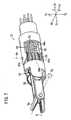
- the working unit 16contains the connecting portion 15 connected to the actuator block 30 and the hollow connecting shaft 48 extending from the connecting portion 15 in the Z1 direction.
- the pulleys 50a, 50b, 50care rotatably disposed in the connecting portion 15, and are connected to drive shafts of the motors 40, 41, 42.
- the pulleys 50a to 50ceach have a coupling.
- Wires 52, 53, 54are wound around the pulleys 50a, 50b, 50c, and extend through a hollow part 48a (see FIG. 7 ) of the connecting shaft 48 to the end working portion 12.
- the types and diameters of the wires 52, 53, 54may be the same.
- the connecting portion 15 of the working unit 16can be separated from the operating unit 14 by performing a predetermined operation in the actuator block 30, and can be subjected to washing, sterilization, maintenance, etc.
- the working unit 16can be changed with another working unit, and the length of the connecting shaft 48 and the mechanism of the end working portion 12 may be selected depending on an intended procedure.
- the structure of the connecting portion 15is such that rotary shafts 40a, 40b, 40c of the motors 40, 41, 42 are fitted into center holes of the pulleys 50a, 50b, 50c.
- the pulleys 50a, 50b, 50ceach have a cross-shaped connecting projection at the lower end in the Y2 direction, and the rotary shafts 40a, 40b, 40c each have a cross-shaped connecting recess.
- the connecting projections and the connecting recessesare engageable with each other, and thereby the rotary motions of the motors 40, 41, 42 are reliably transmitted to the pulleys 50a, 50b, 50c.
- the connecting projections and the connecting recessesare not engaged with each other when the pulleys 50a, 50b, 50c and the motors 40, 41, 42 are not in the original points.
- the shapes of these engaging portionsare not limited to the cross shape.
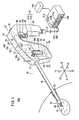
- a camera (an ID recognizer or an image-capturing means) 106 and two white LEDs (a lighting means) 105are disposed on the contact surface 30a between the actuator block 30 and the bridge 28.
- the contact surface 30ais an X-Y plane, which is brought into contact with an end surface of a cover 37 in the connecting portion 15 of the working unit 16.
- the camera 106is for capturing an image of an image code 104 as described later (see FIG. 5 ), and may be a CCD or CMOS camera.
- the white LEDs 105have an optical axis in the direction of illuminating the image code 104, so that the image code 104 can be recognized more reliably by the camera 106.
- the white LEDs 105are horizontally symmetrically disposed with reference to the camera 106, and thereby the image code 104 can be irradiated with a balanced light.
- the white LEDs 105may be vertically arranged with the camera 106 interposed therebetween, and three or more LEDs 105 may be disposed at equal intervals. Only one LED 105 may be used as long as it has a sufficient light intensity.
- a working unit detecting means 107 for detecting the presence of the connecting portion 15is disposed in the vicinity of the Z2 direction end.
- the working unit detecting means 107has a phototransmitter 107a and a photoreceiver 107b facing each other.
- the phototransmitter 107a and the photoreceiver 107bare arranged facing each other in the X direction and being close to each other.
- the phototransmitter 107amay be an LED
- the photoreceiver 107bmay be a photodiode.
- a two-dimensional image code (an ID holder) 104is placed in the vicinity of the Z2 direction end.
- the image code 104has a substantially square matrix shape, and black and white patterns are printed on the divisions thereof.
- the image code 104is attached to a plate 104a in the X-Y plane, and is positioned at an appropriate distance P from the rear end of the cover 37 in the forward Z1 direction.
- the image code 104contains information of the working unit 16, such as the identification data, specification, time stamp (manufacturing date, etc.), serial number, and usage count upper limit.
- the identification data of the working unit 16, which is included in the image code 104,has a different value, so as to identify the working units.
- the connecting portion 15may have a plurality of image codes 104.
- image codes 104In the case of using two image codes 104, one may have individual specific information such as the identification data, manufacturing date, and serial number, and the other may have common model information such as the specification or usage count upper limit.
- the image code 104is not limited to the two-dimensional data, and may be one-dimensional bar code.
- the colors of the patterns printed on the divisions of the image code 104are not limited to black and white, and may be an infrared absorbing color and an infrared reflecting color, or three or more colors for indicating information based on difference in color.
- the information in the image code 104is read by the controller 514, and shown in a working state display 530 (see FIG. 1 ). Alternatively the read information may be judged, and a caution or warning may be shown on the working state display 530.
- the small detection piece 109projects backward in the lower end on the rear surface of the pulley container 300.
- the detection piece 109is inserted between the phototransmitter 107a and photoreceiver 107b, and blocks a light form the phototransmitter 107a, and the image code 104 faces the camera 106 at the focal distance P.
- the image code 104 and the camera 106are covered in a substantially closed region with the cover 37.
- contamination of the image code 104 and the camera 106can be prevented, and the image can be stably captured while blocking ambient light.
- the imagecan be stably taken under the lighting by the white LEDs 105.
- the cover 37 for covering the image code 104 and the camera 106may be disposed on the actuator block 30.
- the relative positions and orientations of the image code 104 and the camera 106are fixed, so that the camera 106 need not recognize the position and orientation of the image code 104. Therefore, a code for recognizing the position and orientation is not required or is reduced, whereby the amount of information that can be included in the image code 104 can be increased.
- the controller 514controls the camera 106 and the white LEDs 105 to receive the identification signal from the image code 104.
- the controller 514only needs to receive the identification signal when the working unit 16 is attached to the actuator block 30, and the camera 106 and the white LEDs 105 can be stopped at any time except when the working unit 16 is attached to the actuator block 30, whereby the processing load and the power consumption can be reduced.
- a visible light, an infrared light, etc.can be used for capturing an image by the camera 106.
- the image of the image code 104can be clearly captured even in a dark place.
- the image code 104may be irradiated with an infrared ray LED.
- the working unit detecting means 107is not limited to the above structure having the phototransmitter 107a and the photoreceiver 107b, and for example may be a limit switch, which is operated by the detection piece 109.
- the controller 514can receive the identification data of the working unit 16 and control the working unit 16 based on the identification data in accordance with the type of the working unit 16.
- the working unit 16 detached from the operating unit 14can be easily washed and sterilized. All electric devices such as motors, switches, and sensors are placed in the operating unit 14, while the mechanical components such as the connecting shaft 48 and the end working portion 12 are placed in the working unit 16, so that the washing efficiency of the working unit 16 is improved. It is preferred that the working unit 16 and the operating unit 14 are separately maintained and washed because the contamination degrees, contamination types, and washing methods are different therebetween.
- levers 206 formed on both sides of the actuator block 30are pressed to be tilted outward and then wedges 206a of the levers 206 are disengaged from engaging pieces 200 formed on both sides of the connecting portion 15. Then, the connecting portion 15 is pulled out upward (in the Y1 direction) and detached from the operating unit 14.
- Three alignment pins 212are disposed on the upper surface of the actuator block 30, and are fitted into mating holes 202 formed on the connecting portion 15 to stably fix the connecting portion 15.
- the connecting portion 15is moved downward (in the Y2 direction) while the three alignment pins 212 is kept at positions for fitting into the mating holes 202.
- the levers 206are moved outward and then return to the original positions, and thereby are engaged with the engaging pieces 200 to complete the attachment.
- the end working portion 12has a three-degree-of-freedom mechanism, which contains a mechanism (a tilt mechanism or a pivot shaft) having a first degree of freedom for rotating a portion of the end working portion 12 that is positioned ahead of a first rotary axis Oy extending in the Y direction, in the yaw directions about the first rotary axis Oy, a mechanism (a roll rotation mechanism) having a second degree of freedom for rotating the portion of the end working portion 12 in the roll direction about a second rotary axis Or, and a mechanism having a third degree of freedom for opening and closing the gripper 59 at the distal end about a third rotary axis Og.
- the first rotary axis Oy of the mechanism having a first degree of freedommay be rotatable and non-parallel to an axis C extending from the proximal end to the distal end of the connecting shaft 48.
- the second rotary axis Or of the mechanism having a second degree of freedommay be rotatable and parallel to the extending axis of the distal end of the end working portion 12 (the gripper 59), the distal end being rotatable.
- the end working portion 12is driven by the wires 52, 53, 54, which are each wound around a corresponding cylinder 60c, 60b, 60a.
- gears 51, 55are rotated by the wires 52, 54, whereby a face gear (not shown) is rotated, and then the distal end can be rotated in the roll direction.
- the gear 51is rotated by the wire 54, whereby the gripper 59 can be opened and closed via the face gear 57 and the gear 58. Further, the distal end can be rotated in the yaw direction by the wires 52, 53, 54 via a main shaft member 62.
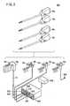
- the controller 514will be described below with reference to FIGS. 9 and 10 .
- the working state display 530, an electric source information display 532, an alarm part 534, an activate reset part 536, the first port 515a, the second port 515b, and the third port 515care disposed on the front face of the controller 514.
- the working state display 530has a liquid crystal display screen for showing the working state or command of the manipulator 10 in order that an operator, an operation assistant, or the like can easily recognize the operating state.
- the first port 515a, the second port 515b, and the third port 515ceach have a receptacle connector 572, to which the manipulator 10 can be connected, and each have an information display and a reset switch 570.
- the internal structure of the controller 514will be described below with reference to FIG. 10 .
- FIG. 10only the components for the first port 515a are shown, and part of the components for the second port 515b and the third port 515c are omitted.
- some componentssuch as a computing part 110 are common to the ports 515a, 515b, 515c and the other components such as a driver 116 are independent.
- the surface structure of the controller 514(see FIG. 9 ) is omitted in FIG. 10 .
- the controller 514has the computing part 110, an electric source part 112, a protector 114, and the driver 116.
- the electric source part 112an electric power from an external electric source 119 is controlled and applied to each component, and a battery 112a is charged.
- the electric power supply of the external electric source 119is automatically changed to the electric power supply of the battery 112a by the electric source part 112.
- the electric source part 112acts as a so-called uninterruptible electric source.
- the battery 112ais connected in parallel to an internal transformer rectifier unit.
- the electric power application to the manipulator 10is stopped by the protector 114 based on information such as operation period information, driver information, and a stop command in the computing part 110.
- the manipulator 10can be immediately stopped by blocking the electric power for the driver 116 using the protector 114.
- the computing part 110is connected to the angle sensors 43, 44, 45, the input sensors 39a, 39b, 39c, and the switch 36. In the computing part 110, based on signals from these components, the operation of the manipulator 10 is determined, a command signal is transmitted to the driver 116, and the state of the manipulator 10 is shown on the working state display 530. The computing part 110 is further connected to the LED 29, and controls the lighting of the LED 29.
- the computing part 110is connected to the camera 106 and the white LEDs 105, and controls the capturing and lighting.
- the computing part 110is connected to and controls each switch and lamp of the working state display 530, the electric source information display 532, the alarm part 534, the activate reset part 536, the first port 515a, the second port 515b, and the third port 515c disposed on the controller 514 (see FIG. 9 ).
- the computing part 110contains a CPU, an ROM, an RAM, etc., and reads and executes a program to perform a software process.
- the driver 116is connected to the motors 40, 41, 42, and the motors 40, 41, 42 are driven based on a command from the computing part 110.
- a movement angle command value for the end working portionis determined from the input sensors 39a, 39b, 39c
- an angle signalis obtained from the angle sensors 43, 44, 45
- the deviation between the movement angle command value and the angle signalis determined
- a compensation processis carried out based the deviation
- a command signalis transmitted to the driver 116.
- the driving system of the motors 40, 41, 42forms a closed loop.
- the computing part 110has an ID recognizer 120, a detachment judgment part 121, an original point recognition part 122, a warning part 124, and a communication part 126.
- the ID recognizer 120can recognize the identification data in the image code 104 via the camera 106.
- the detachment judgment part 121the identity of the working unit 16 is judged based on the identification data recognized by the ID recognizer 120 when the working unit 16 is attached to or detached from the actuator block 30 of the operating unit 14.
- each of the trigger lever 32 and the composite input part 34can be used not only as an operation input means but also a recognition means for detecting the detachment of the operating unit 14.
- the original point recognition part 122recognizes whether the end working portion 12 is in the predetermined original point or not, based on a signal from the angle sensors 43, 44, 45.
- a detachment warningis provided by the warning part 124.
- the warning part 124monitors identification data obtained from the ID recognizer 120 and recognizes that a working unit 16 is reattached. In this case, if the obtained identification data is identical with identification data that was recognized before detachment, the warning part 124 stops the detachment warning. If the obtained identification data is different from identification data that was recognized before detachment, an improper connection warning is provided by the warning part 124.
- the detachment warning and the improper connection warningmay be provided as a sound or voice, and also may be shown as a message in the working state display 530. It is preferred that the detachment warning and the improper connection warning can be easily distinguished. In the case of using the sound or voice, for example, the warnings may be provided as buzzer sounds with different blowing intervals or frequencies.
- the communication part 126is connected to an external LAN (Local Area Network) 600, and information can be sent and received therebetween.
- LANLocal Area Network
- the electricity supply to the driver 116is stopped by the computing part 110 via the protector 114.
- a plurality of (e.g. three) controllers 514may be connected to the LAN 600.
- a usage history management means of the host computer 602is connected to the LAN 600.
- a usage history table 604 shown in FIG. 12is recorded on an internal recording means.
- a usage history data corresponding to an identification numberis sent and received between the host computer 602 and each of the controllers 514, and is managed by the host computer 602.
- the host computer 602may have such a structure as separated from the controllers 514, and one of the controllers 514 may have the usage history table 604 and act as the host computer 602.
- the LAN 600may be a wired or wireless means, a means using an electric source line, etc., and may be replaced with another communication means.
- the LAN 600is not limited to a local network, and may be, for example, a network shared by a plurality of medical facilities.
- the communication meansmay be such that the host computer 602 is prepared by a manipulator manufacturer, each controller 514 is connected to the host computer 602 over a common network, and the usage history is managed by the manufacturer.
- the usage history table 604has columns for the identification data, specification, usage time, usage count, sterilization date, error history, manufacturing date, and remarks. Further, individual information such as a corrected phase value (or an corrected original point value) may be recorded on the usage history table 604.
- the identification data of the working unit 16is shown in the identification data column.
- the specification of the working unit 16, particularly the type of the end working portion 12, the length of the connecting shaft 48, etc.,is shown in the specification column.
- the number of using a corresponding working unit 16is shown in the usage count column.
- the date of last sterilizing the working unit 16is shown in the sterilization date column.
- the history information of an error generated in a corresponding working unit 16is shown in the error history column.
- the manufacturing date of a corresponding working unit 16is shown in the manufacturing date column. Other optional information can be written on the remarks column.
- the information in the sterilization date column and the remarks columnare input by an input means such as a keyboard or a mouse in the host computer 602.
- connection information table 606is shown on a monitor 602a of the host computer 602.
- Information on connection ports 1 to 3 of the three controllers 514, which are connected to the host computer 602are shown in the connection information table 606.
- the usage history data of the connected portsare shown in a corresponding section of the connection information table 606 with reference to the usage history table 604.
- the unconnected portsare shown as "unconnected”.
- each controller 514controls the camera 106 and the white LEDs 105, receives the identification signal of the image code 104, and receives the usage history data corresponding to the identification signal from the host computer 602. Further, after the working unit 16 is detached from the actuator block 30, the usage history data is updated by each controller 514, and is transmitted to the host computer 602. Then, the host computer 602 records the obtained usage history data on the usage history table 604, based on the identification signal.
- the position of the usage history management meansis not limited to the host computer 602, and a management part 608 having the same function as the usage history management means may be disposed in one or all of the controllers 514 as shown by a dotted line in FIG. 11 .
- management part 608When the management part 608 is disposed in one of the controllers 514, information are sent and received between the management part 608 and the other controllers 514 to centrally manage the usage history table 604 in the same manner as the host computer 602.
- one management part 608is made effective by operating a selecting switch, the other management parts 608 being ineffective.
- the information in the usage history table 604may be dispersion-managed. For example, when a certain working unit 16 is connected to one of the controllers 514, the controller 514 may communicate with all the other controllers 514 and obtain, from all the other controllers 514, the current usage history data corresponding to the identification data of the connected working unit 16. Then, the information of the working unit 16 may be updated and managed in the management part 608 of the connected controller 514. In controllers 514 that have transmitted the information to the controller 514, from which the current usage history data is transmitted, the information may be deleted or flagged as a sign of transmitted data.
- the usage history data of the working unit 16may be updated and managed in the controller 514 to which the working unit 16 is connected most recently (or the working unit 16 is being connected). Further, the usage history data may be updated and managed in the controller 514 to which the working unit 16 is connected first, and may be redundantly managed in all the controllers 514.
- the monitor 602amay be connected to the controller 514.
- the host computer 602may be connected as a display device to the LAN 600.
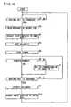
- the controller 514receives a signal from the working unit detecting means 107, to confirm whether the working unit 16 is connected or not to the actuator block 30 of the operating unit 14. When the working unit 16 is not connected, the controller 514 is kept in the standby state, and when the working unit 16 is connected, control goes to step S2.
- the camera 106 and the white LEDs 105are controlled to read the information of the image code 104.
- the informationmay include the identification data, specification, and manufacturing date. After the information is obtained, the camera 106 and the white LEDs 105 are stopped.
- the identification data and information on the connected portare transmitted from the controller 514 to the host computer 602, and the controller 514 requests the host computer 602 to send data.
- the usage history table 604is searched by the host computer 602 based on the transmitted identification data, and the corresponding usage history data is transmitted from the host computer 602 to the controller 514.
- the usage history data corresponding to the identification datais shown in the corresponding column of the connection information table 606.
- this informationis transmitted to the controller 514 and another column for the identification data is formed in the usage history table 604.
- the usage time datais assigned to a variable Hr
- the usage count datais assigned to a variable No
- the error history datais assigned to a variable Er.
- the value 0is assigned to each of the variables Hr, No, and Er.
- the variable Ermay be a binary number data having a bit number representing the number of error types.
- a timeris started to measure the operating time ⁇ Hr of the connected working unit 16.
- the operating time ⁇ Hrmay be measured only when the working unit 16 is in the drive mode.
- step S6an error detecting process is carried out.
- the step S7is carried out when an error occurs, and the step S8 is carried out when errors do not occur.
- step S7a process appropriate for the generated error is carried out, and the bit corresponding to the error is set to "1" in the variable Er. After the setting, the history of the error occurrence can be recognized by referring to the bit. Then, the step S8 is carried out.
- step S8a signal is obtained from the working unit detecting means 107, to confirm whether the working unit 16 is detached from the actuator block 30 of the operating unit 14 or not.
- step S9is carried out when the working unit 16 is detached, and the step S6 is carried out again when the working unit 16 is not detached.
- step S9when the timer is stopped, the operating time ⁇ Hr is obtained, and the variable Hr is updated in the manner of Hr ⁇ Hr+ ⁇ Hr. Further, the variable No is incremented in the manner of No ⁇ No+1.
- the identification data of the detached working unit 16, the information on the detached port, and the variables No, Hr, and Erare transmitted from the controller 514 to the host computer 602, and the controller 514 requests the host computer 602 to write data.
- the usage history table 604is searched by the host computer 602 based on the transmitted identification data, to write the corresponding usage history data. Therefore, even when the host computer 602 is requested to send data by the three controllers 514, the correct usage history data corresponding to the identification data of the working unit 16 can be transmitted from the host computer 602. Then, the system is returned to the step S1.
- connection information table 606In the host computer 602, the information of the corresponding column in the connection information table 606 is hidden, and the sign "unconnected" is displayed.
- the image code 104 and the camera 106are not in contact with each other, so that the identification data of the working unit 16 can be transmitted without electric powers and electric contacts, and the working unit 16 can be easily washed and sterilized. Further, communication errors are not caused owing to the absence of electrical contacts. Electrically noncontact type devices are generally more durable than contact type devices.
- image informationVarious information are shown as image information in the image code 104, and thereby contactless communication can be easily achieved.
- the controllers 514are connected to the host computer 602 via the LAN 600, and can access the usage history table 604. Therefore, the usage history can be preferably obtained regardless of which controller 514 is connected to the working unit 16.
- the image code 104is positioned in the vicinity of the rear end of the connecting portion 15, whereby the distance between the image code 104 and the camera 106 can be short, and the identification data is reliably transmitted.
- the position of the end working portion 12is calculated using e.g. the original position as a reference. Therefore, when the working unit 16 is changed with another one during an operation, it is desirable that the working unlit 16 is detached after the end working portion 12 and the pulleys 50a to 50c of the working unit 16 are precisely positioned at axial positions corresponding to the original points.
- a certain alarmmay be sounded for the working unit 16 to be reattached.
- the working unit 16needs to be identified to prevent the attachment of another working unit.
- the working unit 16can be identified based on the identification data from the image code 104, and when another working unit is attached, a certain alarm may be sounded.
- a manipulator 10a according to an unclaimed modification example of the manipulator 10will be described below with reference to FIG. 15 .
- the same components as the manipulator 10are represented by the same numerals, and explanations therefor are omitted.
- an RFID 610 and a transmitter-receiver 612are used instead of the image code 104 and the camera 106, and the white LEDs 105 are removed.
- the RFID (Radio Frequency Identification, an ID holder) 610is disposed in the vicinity of the rear end of the connecting portion 15 in the manipulator 10a.
- the RFIDis a wireless authentication system, which has a small IC chip containing the product identification data and wirelessly reads or updates information.
- the RFIDis referred to also as a wireless tag, IC tag, or ⁇ chip.
- the RFID 610contains information equal to those of the above described image code 104, i.e. the information such as the identification data, specification, time stamp (manufacturing date, etc.), serial number, and usage count upper limit of the working unit 16.
- the RFID 610is recordable, and individual information such as the usage count, usage time, error history, sterilization date, and corrected phase value (or corrected original point value) are recorded thereon.
- the transmitter-receiver (an ID recognizer, data transmitter) 612is disposed such that it faces the RFID 610 when the connecting portion 15 is connected to the actuator block 30. Information is sent and received between the transmitter-receiver 612 and the RFID 610 via a radio wave.
- the relative positions and orientations of the RFID 610 and the transmitter-receiver 612are fixed when the connecting portion 15 is attached to the actuator block 30. Therefore, the radio wave directivity of each of the RFID 610 and the transmitter-receiver 612 is narrowed, and the main lobe of the directivity is directed toward the opposite component to strengthen the radio wave in the direction, and thus, the sending and receiving can be reliably carried out under reduced electric power.
- a two-dotted line 614represents an axis, on which the strength and sensitivity of the radio wave transmitted and received between the RFID 610 and the transmitter-receiver 612 are largest. It is preferred that a direction of the RFID 610 with the strongest directivity is completely aligned with a direction of the transmitter-receiver 612 with the strongest directivity. Practically, in the main lobe beam width, -3 dB power patterns of the RFID 610 and the transmitter-receiver 612 may be directed to each other, for example.
- the RFID 610 and the transmitter-receiver 612are remarkably close to each other. Such a short-distance system with small energy results in a reduced electric power consumption and no possibility of interference.
- a 13.56-MHz-band, 2.45-GHz-band, or 5-GHz-band RFIDcan be suitably used in such a system, in which the RFID 610 and the transmitter-receiver 612 are disposed in the fixed relative positions at a small distance.
- the controller 514controls the manipulator 10a in accordance with the RFID 610 and the transmitter-receiver 612, although the detailed description therefor is omitted.
- the RFIDis recordable, and data such as the usage count, usage time, error history, and sterilization date may be written thereon.
- a rewriting preventing meansmay be used to prevent the data such as the identification data, serial number, and specification in the RFID from being carelessly changed.
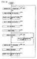
- the controller 514controls the manipulator 10a as shown in FIG. 16 .
- the steps S101 to S103 of FIG. 16correspond to the steps S1 to S3 of FIG. 14
- the steps S105 to S111 of FIG. 16correspond to the steps S4 to S10 of FIG. 14 .
- the step S102is different from the step S2 in that the information is read from the RFID 610, instead of the image code 104.
- the step S104is carried out between the steps S103 and S105.
- Informationis written on the RFID 610 in the step S104.
- the informationcontains all the corresponding usage history data in the usage history table 604 of the host computer 602 (see FIG. 12 ).
- the RFID 610 and the transmitter-receiver 612are not in contact with each other, and the identification data of the working unit 16 can be obtained without electrical contacts and electricity storages such as batteries.
- the working unit 16can be easily washed and sterilized. Signals can be transmitted between the RFID 610 and the transmitter-receiver 612 through a radio wave, and thereby contactless communication can be easily achieved.
- the RFID 610has a small, simple structure capable of easily communicating.
- the usage history datais received to and recorded on the RFID 610, and the usage history of each working unit 16 can be easily managed.
- the transmitter-receiver 612may be an antenna.
- An electrical circuit, which is connected to the transmitter-receiver 612,may be disposed in the operating unit 14 or the controller 514.
- the identification datamay be contactless-transmitted between the working unit 16 and the operating unit 14 through a magnetism or light (e.g. infrared communication), other than the image information of the image code 104 and the radio wave of the RFID 610.
- the working unit 16can be easily cleaned and washed also in this case.
- a medical manipulator system 1100according to an unclaimed example will be described below. First, components of the medical manipulator system 1100 and the corresponding components of the above mentioned manipulator system 500 will be described.
- the main components of the medical manipulator system 1100a manipulator 1102 (a), 4 control unit 1104 (b), a surgical instrument 1106 (c), a surgical instrument control unit 1112 (d), a surgical tool controller 1107 (e), a surgical tool 1122 (f), a shaft 1116 (g), a handle 1110 (h), a button 1114 (i), a transmitter 1210 (j), a motor 1212 (k), a communication circuit 1216 (1), a drive assembly 1204 (m), an identifier 1300 (n), and an identification signal reader 1302 (o), correspond respectively to the components of the manipulator system 500: the manipulator 10 (a), the controller 514 (b), the working unit 16 (c), the actuator block 30 (d), the connecting portion 15 (e), the end working portion 12 (f), the connecting shaft 48 (g), the grip handle 26 (h), the trigger lever32 (i), the RFID 610 (j), the motors 41 to 42 (k), the transmitter-receiver 612 (1), the pulleys 50a to
- the manipulator system 1100may include a medical manipulator 1102 and a control unit 1104.
- the manipulator 1102may include a surgical instrument (working unit) 1106 and a surgical tool control mechanism 1108.
- the surgical instrument 1106may include a surgical tool controller 1107, a surgical tool 1122, and a shaft 1116.
- the shaft 1116has a first end 1118 and a second end 1120 opposite to the first end 1118.
- the surgical tool 1122mounts to the first end 1118 of the shaft 1116 using a variety of mechanisms as known to those skilled in the art both now and in the future.
- the surgical tool controller 1107mounts to the second end 1120 of the shaft 1116 using a variety of mechanisms as known to those skilled in the art both now and in the future.
- the term “mount”includes join, engage, unite, connect, associate, insert, hang, hold, affix, attach, fasten, bind, paste, secure, bolt, screw, rivet, solder, weld, and other like terms.
- the surgical tool control mechanism 1108may be mechanical, electro-mechanical, and/or electrical as known to those skilled in the art both now and in the future.
- the surgical tool control mechanism 1108may include a handle 1110 and a surgical instrument control unit (actuator unit) 1112. A surgeon maneuvers and manipulates the handle 1110 to perform minimally invasive surgical procedures using the surgical tool 1122 as known to those skilled in the art both now and in the future.
- the handle 1110may include a variety of control structures that may be rotated, depressed, toggled, etc. to indicate the desired movement of the surgical tool 1122.
- the handle 1110includes a button 1114 that the surgeon may depress to cause opening and closing of the surgical tool 1122.
- the surgical tool control mechanism 1108is electrically connected to the control unit 1104 through cables within a harness 1115.
- the control unit 1104sends and receives electrical signals through the harness 1115 to/from the surgical tool control mechanism 1108 which controls movement of the surgical tool through a coupling with the surgical tool controller 1107.
- control softwarereceives electrical signals indicating movement of the button 1114 and transforms the movement to appropriate signals for an electro-mechanical system to effect movement of the surgical tool 1122.
- the electrical signalsmay be analog or digital.
- the control unit 1104may further convert angle measurements received from transducers mounted in the handle 1110 to determine control commands that are transmitted to the surgical tool control mechanism 1108 which controls the surgical tool 1122.
- the surgical tool controller 1107may include a plurality of drive assemblies 1204, a plurality of cables 1206, a plurality of connectors 1208, and a transmitter (ID holder) 1210.
- the transmitter 1210may include a RFID.
- the shaft 1116includes an elongate tube through which the plurality of cables 1206 extend.
- the plurality of cables 1206operably couple the surgical tool 1122 with the surgical tool controller 1107.
- the surgical tool 1122may be of many different types including devices specifically designed for cutting, scraping, suturing, grasping, etc.
- the surgical tool control mechanism 1108may include a plurality of motors 1212, a plurality of control cables 1214, a communication circuit (ID recognizer) 1216, and a control wire 1218 mounted within the surgical instrument control unit 1112.
- the communication circuit 1216may include a receiver.
- the transmitter 1210communicates an identifier to the communication circuit 1216.
- the identifieridentifies the type of the surgical tool 1122 so that the manipulator system 1100 operates-as-desired.
- the communication circuit 1216receives the identifier and communicates the identifier to the control unit 1104 through the control wire 1218 contained within the harness 1115.
- the control unit 1104receives the identifier from the communication circuit 1216.
- the control unit 1104interprets the movement considering the identified surgical tool type and provides control commands to the plurality of motors 1212 through the plurality of the control cables 1214 contained within the harness 1115.
- the surgical instrument 1106is removable from the surgical tool control mechanism 1108 so that a variety of surgical tools may be easily and quickly interchanged.
- the plurality of motors 1212releasably engage with the plurality of drive assemblies 1204 through the plurality of connectors 1208 to physically connect the surgical tool control mechanism 1108 to the surgical instrument 1106.
- the plurality of drive assemblies 1204include mechanical components that translate commands from the control unit 1104 into mechanical movement of the surgical tool 1122.
- the plurality of motors 1212create rotational torque that rotates the plurality of drive assemblies 1204.
- the rotation of the plurality of drive assemblies 1204causes translational movement of the plurality of cables 1206 which causes movement of the surgical tool 1122.
- the surgical tool 1122may comprise a variety of surgical devices for cutting, scraping, suturing, etc.
- the plurality of cables 1206may effect different types of movement of the surgical tool 1122.
- the control unit 1104recognizes the type of the surgical tool 1122 and generates appropriate control commands to the plurality of motors 1212 based on the type of the surgical tool 1122.
- the surgical tool controller 1107may include the plurality of drive assemblies 1204, the plurality of cables 1206, the plurality of connectors 1208, and an identifier (ID holder) 1300.
- the identifier 1300may be mounted to an exterior surface of the surgical instrument 1106.
- the identifier 1300is mounted to an exterior surface of the surgical tool controller 1107 adjacent to the surgical tool control mechanism 1108.
- the identifier 1300may include a bar code as known to those skilled in the art both now and in the future.
- the surgical tool control mechanism 1108may include the plurality of motors 1212, the plurality of control cables 1214, an identification reader (ID recognizer) 1302, and the control wire 1218 mounted within the surgical instrument control unit 1112.
- the identification reader 1302may include a bar code reader that reads identification signals of the identifier 1300 using an infrared signal.
- the identification reader 1302reads identification signals of the identifier 1300 and communicates the signals of the identifier 1300 to the control unit 1104 through the control wire 1218 contained within the harness 1115.
- the control unit 1104receives the identifier from the identification reader 1302.
- the control unit 1104interprets the movement considering the identified surgical tool type and provides control commands to the plurality of motors 1212 through the plurality of control cables 1214 contained within the harness 1115 as discussed with reference to FIG. 19 .
- the identification datacan be contactless-transmitted between the surgical tool controller 1107 and the surgical tool control mechanism 1108, whereby the surgical tool controller 1107 has a structure with no electrical contacts and can be easily washed and sterilized.
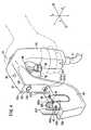
- the working unit 16is connected to the operating unit 14 handled by a human hand, the working unit can be used, for example, in a surgical robotic system 700 shown in FIG. 20 .
- the surgical robotic system 700has a robotic arm 702 and a console 704, and the working unit 16 is connected to the distal end of the robotic arm 702.
- the robotic arm 702has, at the distal end, the same mechanism as the above described actuator block 30, whereby the working unit 16 can be connected thereto and driven.
- a manipulator 10 in the systemhas the robotic arm 702 and the working unit 16.
- the robotic arm 702may be of a stationary type, an autonomous mobile type, or the like, as long as it can move the working unit 16.
- the console 704may be of a table type, a control panel type, or the like.
- the robotic arm 702has six or more independent joints (rotary shafts, slidable shafts, etc.), whereby the position and direction of the working unit 16 can be optionally controlled.
- the distal end 708 of the robotic arm 702is integral with an actuator block 30.
- the actuator block 30has the camera 106 (or the transmitter-receiver 612), the white LEDs 105, and the working unit detecting means 107, and the connecting portion 15 of the working unit 16 has the image code 104 (or the RFID 610) and the detection piece 109.
- the robotic arm 702is driven under the control of the console 704, and may be driven by a program for automatic operation, by a joystick (a robotic operating unit) 706 disposed in the console 704, or by a combination thereof.
- the console 704has a function of the above-described controller 514.
- the console 704has two joysticks 706 and a monitor 710, and the joysticks 706 are used as mechanisms provided by removing the actuator block 30 from the operating unit 14.
- Two robotic arms 702can be independently controlled by the two joysticks 706 though not shown.
- the two joysticks 706are positioned such that they can be easily handled by both hands. Information such as an endoscopic image is shown in the monitor 710.
- the joysticks 706can be moved upward, downward, rightward, or leftward, and can be twisted or tilted.
- the robotic arm 702is moved in accordance with the motions.
- Each of the joysticks 706may be a master arm.
- a communication means between the robotic arm 702 and the console 704may be a wired or wireless means, a network means, or a combination thereof.
- a manipulator (10)comprises an actuator block (30) and a working unit (16) attachable to and detachable from the actuator block (30).
- the actuator block (30)has a motor (40, 41, 42), the working unit (16) has a connecting shaft (48) and an end working portion (12) disposed at the distal end thereof, and the end working portion (12) is rotated in conjunction with the motor (40, 41, 42).
- the working unit (16)further has a two-dimensional code (104) holding an identification signal
- the actuator block (30)further has an infrared camera (106) for recognizing the identification signal in the code (104) and supplying it to a controller (514), is the camera (106) being not in contact with the code (104).
- the controller (514)controls the working unit (16) based on the supplied identification signal.
Landscapes
- Health & Medical Sciences (AREA)
- Surgery (AREA)
- Life Sciences & Earth Sciences (AREA)
- Engineering & Computer Science (AREA)
- Animal Behavior & Ethology (AREA)
- General Health & Medical Sciences (AREA)
- Biomedical Technology (AREA)
- Heart & Thoracic Surgery (AREA)
- Medical Informatics (AREA)
- Molecular Biology (AREA)
- Nuclear Medicine, Radiotherapy & Molecular Imaging (AREA)
- Veterinary Medicine (AREA)
- Public Health (AREA)
- Robotics (AREA)
- Oral & Maxillofacial Surgery (AREA)
- Pathology (AREA)
- Physics & Mathematics (AREA)
- Electromagnetism (AREA)
- Manipulator (AREA)
- Eye Examination Apparatus (AREA)
Abstract
Description
- The present invention relates to a manipulator and a manipulator system for controlling the manipulator, more specifically to a manipulator system comprising a manipulator, which contains an actuator unit having an actuator and a working unit, attachable to and detachable from the actuator unit, having a working portion movable in conjunction with the actuator.
- According to laparoscopic surgery, it is customary to form a plurality of holes in the abdominal part of the patient, insert an endoscope and a manipulator (or forceps) into the respective holes, and perform the surgical operation while images captured by the endoscope are being observed on a display monitor by the surgeon. Since such a laparoscopic surgical operation does not require the abdominal cavity to be opened, the burden on the patient is small and the number of days which the patient needs to recover and spend in the hospital until they are allowed to come out of hospital is greatly reduced. For these reasons, the laparoscopic surgical operation is expected to find an increased range of applications.
- A manipulator system is composed of a manipulator body and a controller therefor, as described in Japanese Laid-Open Patent Publication No.
2004-105451 - The working unit has a slender connecting shaft and an end working portion (also referred to as an end effector) disposed at the distal end of the connecting shaft. A motor for driving the end working portion via a wire is disposed in the operating unit. The wire is wound around a pulley in the vicinity of the proximal end. The motor in the operating unit is driven by the controller, whereby the wire is moved via the pulley.
- The working unit does not contain an electronic device such as a sensor in view of easily carrying out washing and sterilization. The positions or original points of the end working portion and the proximal end pulley cannot be directly detected, and the position of the end working portion is calculated based on rotation of the motor.
- The working unit may be a gripper, a pair of scissors, an electric surgical knife, an ultrasonic surgical knife, a medical drill, or the like, and may be selected depending on a procedure in a laparoscopic operation. The working unit is removable from the operating unit, and when the working unit is attached to the operating unit, the pulley at the proximal end is engaged with a rotary shaft of the motor in the operating unit.
- In such a system intended to connect a plurality of different working units to one operating unit, it is necessary to determine a motor phase as only one position, at which all the working units can be attached and detached (see Japanese Laid-Open Patent Publication No.
2004-105451 - Conventional manipulator systems are described in Japanese Laid-Open Patent Publication Nos.
2004-105451 2004-208922 US. Patent No. 6331181 , for example. - In a system proposed in Japanese Laid-Open Patent Publication No.
2004-105451 - In a system described in Japanese Laid-Open Patent Publication No.
2004-208922 - In a system described in
US. Patent No. 6331181 , a memory for obtaining identification data is mounted in a medical manipulator disposed at a distal end, and a controller receives the identification data to control a tool. The memory is an ROM, a flash memory, or the like, and the identification data is transmitted through an electrical contact. - When surgery is traditionally performed, there is a long incision made so the surgeon can view and repair the internal parts of the patient. The long incision site can be a significant concern because it is subject to infection and is often the most traumatic and painful part of the patient's recover. In recent years, many surgeons have been using endoscopic tools and performing minimally invasive surgery, thereby vastly reducing the size of the incision.
- Robotic tools have been developed to further improve the minimally invasive surgical process. These tools are highly specialized. They must perform the function that a surgeon would in a miniaturized manner. Surgeons perform many different functions on internal organs such as cutting, scraping, and suturing. Different surgical tools are required for each of these functions. A different surgical device could be made for each surgical tool, but it is more cost effective to simply change the surgical tool mounted to the surgical device for each function. To control the surgical tool correctly, the robotic surgical device must identify the surgical tool attached to the surgical instrument.
- In a case where various working units are attached to an actuator unit, it is necessary for a controller to correctly control each working unit in accordance with the type, and accordingly the identification data thereof is required.
- Further, the position of the end working portion is calculated based on, e.g. the original point of the motor as described above. Thus, when a working unit is changed with another working unit during an operation, it is desirable that the working unit is detached from the actuator unit after precisely placed at an axial position corresponding to the original point. When the working unit is detached in a state where it is not placed at the position corresponding to the original point, a certain alarm may be sounded for the working unit to be reattached. In this case, the working unit needs to be identified to prevent the attachment of another working unit.
- In the above system of
US-Patent No. 6331181 , the identification data of the tool can be read from the ROM, and the working unit can be controlled based on the identification data in accordance with the type. However, as described above, it is desirable that the working unit contains no electronic devices, particularly no electrical contacts, in view of easily carrying out washing and sterilization after an operation. - It is preferred that the usage history of each working unit can be obtained based on the identification data from the viewpoint of easily managing the working unit. However, in a case where a plurality of controllers to be connected are provided, when the usage history of a working unit is stored in a certain controller and then the working unit is connected to another controller, the other controller inconveniently cannot recognize the usage history of the working unit.
- The
US 2004/133189 A1 discloses a surgical operation apparatus comprising a hook type treatment jig provided with a probe. The hook type treatment jig contains an energy receiving unit connector which has an information exchange unit and a storage unit storing ID information of a surgical instrument. An energy transmitting connector of the surgical operation apparatus also has an information exchange unit. When the energy transmission unit connector is coupled to the energy receiving unit connector, the information exchange unit reads information peculiar to the hook type treatment jig from the identification information storage unit by radio. A control circuit recognizes a type of a treatment jig as, for example, a hook type treatment jig based on information read by the information exchange unit to set a drive condition in an oscillation circuit in a state suited to driving of the probe. - It is one of the objects of the present invention to provide a manipulator system which is capable of obtaining identification data of a working unit.
- It is another one of the objects of the present invention to provide a manipulator system in which a working unit can be easily washed and sterilized.
- It is another one of the objects of the present invention to provide a working unit having a structure without electrical contacts in a manipulator.
- According to the present invention, this object is achieved by a manipulator system of
claim 1. - The manipulator system comprises a manipulator and a controller therefor, and the manipulator comprises an actuator unit and a working unit attachable to and detachable from the actuator unit. The actuator unit contains an actuator, the working unit contains a shaft and an end working portion disposed at a distal end of the shaft, and the end working portion is rotated in conjunction with the actuator around an axis non-parallel to the shaft. The working unit further contains an ID holder for holding an identification signal, and the actuator unit further contains an ID recognizer for recognizing the identification signal in the ID holder and supplying the identification signal to the controller, the ID recognizer being not in contact with the ID holder. The controller controls the working unit based on the supplied identification signal.
- Thus, the ID holder and the ID recognizer, which are not in contact with each other, are used for obtaining the identification data of the working unit, so that the working unit can be free of electrical contracts. Therefore, the working unit can be easily washed and sterilized, and a communication error is not caused owing to the absence of electrical contacts in the system. Electrically noncontact type devices are generally more durable than contact type devices.
- An exemplary embodiment of the present invention provides a device and a method of identifying the surgical tool mounted to a robotic surgical device so that the robotic control system can correctly and reliably control the surgical tool during a surgical procedure. In an exemplary embodiment, the device includes, but is not limited to, a surgical instrument and a surgical tool control mechanism. The surgical instrument includes, but is not limited to, a surgical tool and a transmitter capable of transmitting an identifier that identifies the surgical tool. The surgical tool control mechanism includes, but is not limited to, a receiver capable of receiving the transmitted identifier.
- In another exemplary embodiment, the device includes, but is not limited to, a surgical instrument and a surgical tool control mechanism. The surgical instrument includes, but is not limited to, a surgical tool and an identifier that identifies the surgical tool. The surgical tool control mechanism includes, but is not limited to, an identification reader capable of reading the identifier.
- Yet another exemplary embodiment provides a method of automatically identifying a surgical tool for use during minimally invasive surgery. The method includes, but is not limited to, receiving an identifier at a receiver and controlling a surgical tool based on the received identifier. The identifier identifies the surgical tool mounted on a surgical instrument.
- Yet another exemplary embodiment provides a method of automatically identifying a surgical tool for use during minimally invasive surgery. The method includes, but is not limited to, reading an identifier on a surgical instrument and controlling a surgical tool based on the read identifier. The identifier identifies the surgical tool mounted on a surgical instrument.
- The above and other objects, features and advantages of the aspects will become more apparent from the following description when taken in conjunction with the accompanying drawings in which a preferred embodiment of the present invention is shown by way of illustrative example.
FIG. 1 is a schematic view of a manipulator system according to an embodiment of the present invention;FIG. 2 is an explanatory view of combination of components for the manipulator system according to the embodiment;FIG. 3 is a side view of the manipulator, a working unit being separated from an operating unit;FIG. 4 is a perspective view of the operating unit;FIG. 5 is a partially sectional perspective view of a connecting portion;FIG. 6 is a partially enlarged perspective view of the operating unit;FIG. 7 is a perspective view of an end working portion;FIG. 8 is an exploded perspective view of the end working portion;FIG. 9 is a front view of a controller;FIG. 10 is a block diagram of the controller;FIG. 11 is a block diagram of a plurality of controllers and a host computer connected thereto via an LAN.FIG. 12 is a chart showing contents of a usage history table;FIG. 13 is a chart showing a connection information table displayed on a monitor;FIG. 14 is a flow chart of processing procedures of the controller for controlling the manipulator;FIG. 15 is a partially sectional perspective view of a manipulator according to an unclaimed modification example;FIG. 16 is a flow chart of processing procedures of the controller for controlling the manipulator according to the modification example;FIG. 17 is a perspective view of a robotic surgical device according to an unclaimed example.FIG. 18 is a view of a robotic surgical device according to a first modification example of the unclaimed example ;FIG. 19 is a view of a robotic surgical device according to a second embodiment; andFIG. 20 is a schematic perspective view of a surgical robotic system having the working unit connected to a distal end of a robotic arm.- A
medical manipulator system 500 according to an embodiment of the present invention will be described below with reference toFIGS. 1 to 20 . Themanipulator system 500 shown inFIG. 1 is used in a laparoscopic operation, etc. - As shown in
FIG. 1 , themanipulator system 500 has amanipulator 10 and acontroller 514. - A
connector 520 is disposed in a connecting portion between themanipulator 10 and thecontroller 514 such that themanipulator 10 is removable from thecontroller 514. - The
manipulator 10 is intended to grasp a part of a living body, a curved needle, or the like using anend working portion 12, thereby carrying out a predetermined procedure. Themanipulator 10 has a basic structure containing an operatingunit 14 and a workingunit 16. Thecontroller 514 electrically controls themanipulator 10, and is connected via theconnector 520 to acable 61 extending from the lower end of agrip handle 26. - The
controller 514 can simultaneously control threemanipulators 10 independently. Sections of thecontroller 514 for controlling the first, second, andthird manipulators 10 are referred to as afirst port 515a, asecond port 515b, and athird port 515c respectively. Ahost computer 602 shown inFIGS. 1 and2 will be hereinafter described. - As shown in
FIG. 2 , themanipulator system 500 may have a variety of structures to be selected. Specifically, operatingunits 14a to 14d can be selectively used as the operatingunit 14, and workingunits 16a to 16d can be selectively used as the workingunit 16. - The
operating unit operating unit 14a may be attached to thecontroller 514. Further, the workingunit unit 16a may be attached to each of the operatingunits 14a to 14d. Thus, an operator can select from combinations of the operatingunits 14a to 14d and the workingunits 16a to 16d depending on the type of the procedure, the procedure proficiency, etc. Among them, the workingunit 16b has scissors as theend working portion 12. The workingunit 16c has a blade-type electric surgical knife, and the workingunit 16d has a hook-type electric surgical knife, as theend working portion 12. The workingunits 16a to 16d have the same arrangement ofpulleys FIG. 1 ) in a connectingportion 15. - The
controller 514 can simultaneously control the threemanipulators 10 as described above, and thus, three of the operatingunits 14a to 14d may be connected to thefirst port 515a, thesecond port 515b, and thethird port 515c, respectively. - The
manipulator 10 having the operatingunit 14 and the workingunit 16 will be described below. - The
manipulator 10 is intended to grasp a part of a living body, a curved needle, or the like using anend working portion 12, thereby carrying out a predetermined procedure. Themanipulator 10 is referred to typically as grasping forceps, a needle driver, etc. - As shown in
FIGS. 1 and3 , themanipulator 10 has the operatingunit 14 grasped and handled by a hand, and the workingunit 16 attachable to and detachable from the operatingunit 14. - In the following description, in
FIG. 1 , the transverse direction of themanipulator 10 is referred to as X direction, the vertical direction is referred to as Y direction, and the extending direction of a connectingshaft 48 is referred to as Z direction. Further, the rightward direction is referred to as X1 direction, the leftward direction is referred to as X2 direction, the upward direction is referred to as Y1 direction, the downward direction is referred to as Y2 direction, the forward direction is referred to as Z1 direction, and the backward direction is referred to as Z2 direction. These expressions represent directions of themanipulator 10 when it is a neutral posture, unless otherwise noted. It should be noted that the expressions are used in the following description for illustrative purpose only, and themanipulator 10 may be used in any orientations, for example, themanipulator 10 may be used upside down. - The working
unit 16 contains theend working portion 12 for carrying out a work, the connectingportion 15 which is connected to an actuator block (actuator unit) 30 of the operatingunit 14, and the long, hollow connectingshaft 48 for connecting theend working portion 12 and the connectingportion 15. The workingunit 16 can be separated from the operatingunit 14 by performing a certain operation in theactuator block 30, and can be subjected to washing, sterilization, maintenance, etc. Theactuator block 30, to which the workingunit 16 is attached, is not limited to a portion containing thereinmotors actuator block 30 also includes acontact surface 30a to abridge 28. - The
end working portion 12 and the connectingshaft 48 are thin, and thereby can be inserted through acylindrical trocar 20 formed on an abdominal part of a patient, etc. into abody cavity 22. By controlling the operatingunit 14, various procedures such as diseased part resection, grasp, suture, and tie-knot can be carried out in thebody cavity 22. - The operating
unit 14 contains the grip handle 26 that is grasped by a human hand, thebridge 28 extending from the upper part of thegrip handle 26, and theactuator block 30 connected to one end of thebridge 28. - As shown in
FIG. 1 , the grip handle 26 of the operatingunit 14 extends from the other end of thebridge 28 in the Y2 direction. The grip handle 26 has a length suitable for being grasped by a human hand, and has atrigger lever 32, acomposite input part 34, and aswitch 36, as an input means. - An LED (indicator) 29 is disposed in a visible position on the upper or side surface of the
bridge 28. TheLED 29 is an indicator for indicating the control state of themanipulator 10, and has such a size that the operator can easily recognize the indication and such a light weight that the handling of themanipulator 10 is not affected. In this embodiment, theLED 29 is disposed in an easily-visible position substantially at the center of the upper surface of thebridge 28. - The
cable 61 connected to thecontroller 514 is disposed on the lower end of thegrip handle 26. The grip handle 26 and thecable 61 may be connected integrally. The grip handle 26 and thecable 61 may be connected by a connector. - The
composite input part 34 is a composite input means for transmitting a command of rotating theend working portion 12 in the roll direction (the axial rotation direction) or the yaw direction (the horizontal direction). For example, in thecomposite input part 34, a first input means may be axially rotated to transmit a command of rotating in the roll direction, and a second input means may be moved in the horizontal direction to transmit a command of rotating in the yaw direction. Thetrigger lever 32 is an input means for transmitting a command of opening and closing a gripper 59 (seeFIG. 1 ) in theend working portion 12. Theswitch 36 is an input means for start-and-stop controlling themanipulator 10. - As shown in
FIGS. 3 and4 ,input sensors composite input part 34 and thetrigger lever 32 respectively. A movement signal (such as an analog signal) detected by theinput sensors controller 514. - The
trigger lever 32 projects in the Z1 direction on the lower side of thebridge 28. The position of thetrigger lever 32 is such that it can be easily handled by an index finger. - The
trigger lever 32 is connected via anarm 98 to thegrip handle 26, and can be moved close to and away from thegrip handle 26. - The
switch 36 is an operation mechanism movable close to and away from thegrip handle 26, and thetrigger lever 32 and theswitch 36 are arranged on the Z1 side of the grip handle 26 in the longitudinal direction of the grip handle 26 (the Y direction). Theswitch 36 is disposed immediately below the trigger lever 32 (on the Y2 side), and athin plate 130 is placed between theswitch 36 and thetrigger lever 32. - The
switch 36 is alternate, and by pushing anoperation button 36a in the Z2 direction, theoperation button 36a is fixed at a pushed position in the Z2 direction and theswitch 36 is locked in an ON state. By pushing theswitch 36 again, theswitch 36 is changed from an ON state to an OFF state, and is moved toward the distal end in the Z1 direction by an elastic body (not shown), thereby returning to the initial position. Theswitch 36 can be kept in an ON or OFF state by these procedures, and it is not necessary to continue pushing theswitch 36. Thus, theswitch 36 only needs to be handled when the ON or OFF state is switched, and thetrigger lever 32 can be handled at any time except when the ON/OFF state is switched. Theswitch 36 and thetrigger lever 32 can be preferably used in combination in this manner. - The protrusion of the
operation button 36a is different between the ON and OFF states, whereby the state of theswitch 36 can be recognized by visually observing or touching theoperation button 36a. - A mode of the
manipulator 10 is changed by theswitch 36. The mode is indicated by lighting of theLED 29 and a certain lamp in thecontroller 514. Specifically, theLED 29 and the lamp are in a green lighting state in a drive mode, and in a non-lighting state in a stop mode. Further, theLED 29 and the lamp are in a green blinking state during an automatically returning step and a reset step, and in the red blinking state during alarm generation. - The mode and operation of the
manipulator 10 are changed by handling theswitch 36. The state of theswitch 36 is read by thecontroller 514. When theswitch 36 is in an ON state, themanipulator 10 is changed to the drive mode by thecontroller 514. When theswitch 36 is changed from the ON state to the OFF state, themotors manipulator 10 is changed to the stop mode after themotors - The drive mode is such a mode that the operating command of the operating
unit 14 is effective for driving themotors motors unit 14. Further, the reset step is such a step that themotors motors unit 14, and thus in the steps, themanipulator 10 is in the automatic mode. - These modes and steps are separately controlled, and the lighting state of the
LED 29 and lamp is changed, by thecontroller 514. - In the
actuator block 30, themotors end working portion 12 are arranged in the longitudinal direction of the connectingshaft 48. Themotors actuator block 30 has a compact flat shape. Theactuator block 30 is disposed at the lower portion on the Z1 direction end of the operatingunit 14. Themotors unit 14 under the control of thecontroller 514. Angle sensors motors controller 514. For example, a rotary encoder is used as theangle sensors - The working
unit 16 contains the connectingportion 15 connected to theactuator block 30 and the hollow connectingshaft 48 extending from the connectingportion 15 in the Z1 direction. Thepulleys portion 15, and are connected to drive shafts of themotors pulleys 50a to 50c each have a coupling. Wires pulleys hollow part 48a (seeFIG. 7 ) of the connectingshaft 48 to theend working portion 12. The types and diameters of thewires - The connecting
portion 15 of the workingunit 16 can be separated from the operatingunit 14 by performing a predetermined operation in theactuator block 30, and can be subjected to washing, sterilization, maintenance, etc. The workingunit 16 can be changed with another working unit, and the length of the connectingshaft 48 and the mechanism of theend working portion 12 may be selected depending on an intended procedure. - The structure of the connecting
portion 15 is such thatrotary shafts motors pulleys pulleys rotary shafts motors pulleys pulleys motors - A camera (an ID recognizer or an image-capturing means) 106 and two white LEDs (a lighting means) 105 are disposed on the
contact surface 30a between theactuator block 30 and thebridge 28. Thecontact surface 30a is an X-Y plane, which is brought into contact with an end surface of acover 37 in the connectingportion 15 of the workingunit 16. Thecamera 106 is for capturing an image of animage code 104 as described later (seeFIG. 5 ), and may be a CCD or CMOS camera. Thewhite LEDs 105 have an optical axis in the direction of illuminating theimage code 104, so that theimage code 104 can be recognized more reliably by thecamera 106. Thewhite LEDs 105 are horizontally symmetrically disposed with reference to thecamera 106, and thereby theimage code 104 can be irradiated with a balanced light. Thewhite LEDs 105 may be vertically arranged with thecamera 106 interposed therebetween, and three ormore LEDs 105 may be disposed at equal intervals. Only oneLED 105 may be used as long as it has a sufficient light intensity. - On an
upper surface 30b of theactuator block 30, on which the connectingportion 15 is mounted, a working unit detecting means 107 for detecting the presence of the connectingportion 15 is disposed in the vicinity of the Z2 direction end. The working unit detecting means 107 has aphototransmitter 107a and aphotoreceiver 107b facing each other. When adetection piece 109 disposed at the rear end of the connectingportion 15 is inserted between the phototransmitter 107a andphotoreceiver 107b and blocks a light from the phototransmitter 107a, the attachment of the connectingportion 15 is detected by the working unit detecting means 107. The phototransmitter 107a and thephotoreceiver 107b are arranged facing each other in the X direction and being close to each other. For example, the phototransmitter 107a may be an LED, and thephotoreceiver 107b may be a photodiode. - As shown in
FIG. 5 , on the upper surface of apulley container 300 in the connectingportion 15, a two-dimensional image code (an ID holder) 104 is placed in the vicinity of the Z2 direction end. For example, theimage code 104 has a substantially square matrix shape, and black and white patterns are printed on the divisions thereof. Theimage code 104 is attached to aplate 104a in the X-Y plane, and is positioned at an appropriate distance P from the rear end of thecover 37 in the forward Z1 direction. - The
image code 104 contains information of the workingunit 16, such as the identification data, specification, time stamp (manufacturing date, etc.), serial number, and usage count upper limit. The identification data of the workingunit 16, which is included in theimage code 104, has a different value, so as to identify the working units. - The connecting
portion 15 may have a plurality ofimage codes 104. In the case of using twoimage codes 104, one may have individual specific information such as the identification data, manufacturing date, and serial number, and the other may have common model information such as the specification or usage count upper limit. - The
image code 104 is not limited to the two-dimensional data, and may be one-dimensional bar code. The colors of the patterns printed on the divisions of theimage code 104 are not limited to black and white, and may be an infrared absorbing color and an infrared reflecting color, or three or more colors for indicating information based on difference in color. - The information in the
image code 104 is read by thecontroller 514, and shown in a working state display 530 (seeFIG. 1 ). Alternatively the read information may be judged, and a caution or warning may be shown on the workingstate display 530. - The
small detection piece 109 projects backward in the lower end on the rear surface of thepulley container 300. When the connectingportion 15 is attached to theactuator block 30, thedetection piece 109 is inserted between the phototransmitter 107a andphotoreceiver 107b, and blocks a light form the phototransmitter 107a, and theimage code 104 faces thecamera 106 at the focal distance P. - At the time, the
image code 104 and thecamera 106 are covered in a substantially closed region with thecover 37. Thus, contamination of theimage code 104 and thecamera 106 can be prevented, and the image can be stably captured while blocking ambient light. Even when theimage code 104 and thecamera 106 are in the closed region, the image can be stably taken under the lighting by thewhite LEDs 105. Thecover 37 for covering theimage code 104 and thecamera 106 may be disposed on theactuator block 30. The relative positions and orientations of theimage code 104 and thecamera 106 are fixed, so that thecamera 106 need not recognize the position and orientation of theimage code 104. Therefore, a code for recognizing the position and orientation is not required or is reduced, whereby the amount of information that can be included in theimage code 104 can be increased. - Whether the working
unit 16 is attached to theactuator block 30 or not can be detected by thecontroller 514 using the working unit detecting means 107. When the workingunit 16 is attached to the actuator block 30 (e.g. at the time point of the attachment, or in the period between the attachment and the substantial start of the procedure), thecontroller 514 controls thecamera 106 and thewhite LEDs 105 to receive the identification signal from theimage code 104. Thus, thecontroller 514 only needs to receive the identification signal when the workingunit 16 is attached to theactuator block 30, and thecamera 106 and thewhite LEDs 105 can be stopped at any time except when the workingunit 16 is attached to theactuator block 30, whereby the processing load and the power consumption can be reduced. - A visible light, an infrared light, etc. can be used for capturing an image by the
camera 106. In the case of using the infrared light, the image of theimage code 104 can be clearly captured even in a dark place. In this case, theimage code 104 may be irradiated with an infrared ray LED. - The working unit detecting means 107 is not limited to the above structure having the phototransmitter 107a and the
photoreceiver 107b, and for example may be a limit switch, which is operated by thedetection piece 109. Thecontroller 514 can receive the identification data of the workingunit 16 and control the workingunit 16 based on the identification data in accordance with the type of the workingunit 16. - It is not necessary to directly applying electricity to the
image code 104, and the connectingportion 15 and the workingunit 16 have no electrical contacts and no electricity storages such as batteries. Thus, the workingunit 16 detached from the operatingunit 14 can be easily washed and sterilized. All electric devices such as motors, switches, and sensors are placed in the operatingunit 14, while the mechanical components such as the connectingshaft 48 and theend working portion 12 are placed in the workingunit 16, so that the washing efficiency of the workingunit 16 is improved. It is preferred that the workingunit 16 and the operatingunit 14 are separately maintained and washed because the contamination degrees, contamination types, and washing methods are different therebetween. - In order to detach the connecting
portion 15 from the operatingunit 14,levers 206 formed on both sides of theactuator block 30 are pressed to be tilted outward and thenwedges 206a of thelevers 206 are disengaged from engagingpieces 200 formed on both sides of the connectingportion 15. Then, the connectingportion 15 is pulled out upward (in the Y1 direction) and detached from the operatingunit 14. Three alignment pins 212 are disposed on the upper surface of theactuator block 30, and are fitted intomating holes 202 formed on the connectingportion 15 to stably fix the connectingportion 15. When the connectingportion 15 is attached to the operatingunit 14, the connectingportion 15 is moved downward (in the Y2 direction) while the threealignment pins 212 is kept at positions for fitting into the mating holes 202. Thus, thelevers 206 are moved outward and then return to the original positions, and thereby are engaged with the engagingpieces 200 to complete the attachment. - As shown in
FIGS. 7 and8 , theend working portion 12 has a three-degree-of-freedom mechanism, which contains a mechanism (a tilt mechanism or a pivot shaft) having a first degree of freedom for rotating a portion of theend working portion 12 that is positioned ahead of a first rotary axis Oy extending in the Y direction, in the yaw directions about the first rotary axis Oy, a mechanism (a roll rotation mechanism) having a second degree of freedom for rotating the portion of theend working portion 12 in the roll direction about a second rotary axis Or, and a mechanism having a third degree of freedom for opening and closing thegripper 59 at the distal end about a third rotary axis Og. - The first rotary axis Oy of the mechanism having a first degree of freedom may be rotatable and non-parallel to an axis C extending from the proximal end to the distal end of the connecting
shaft 48. The second rotary axis Or of the mechanism having a second degree of freedom may be rotatable and parallel to the extending axis of the distal end of the end working portion 12 (the gripper 59), the distal end being rotatable. - The
end working portion 12 is driven by thewires corresponding cylinder - In the
end working portion 12, gears 51, 55 are rotated by thewires gear 51 is rotated by thewire 54, whereby thegripper 59 can be opened and closed via theface gear 57 and thegear 58. Further, the distal end can be rotated in the yaw direction by thewires main shaft member 62. - The
controller 514 will be described below with reference toFIGS. 9 and10 . - As shown in
FIG. 9 , the workingstate display 530, an electricsource information display 532, analarm part 534, an activatereset part 536, thefirst port 515a, thesecond port 515b, and thethird port 515c are disposed on the front face of thecontroller 514. - The working
state display 530 has a liquid crystal display screen for showing the working state or command of themanipulator 10 in order that an operator, an operation assistant, or the like can easily recognize the operating state. - The
first port 515a, thesecond port 515b, and thethird port 515c each have areceptacle connector 572, to which themanipulator 10 can be connected, and each have an information display and areset switch 570. - The internal structure of the
controller 514 will be described below with reference toFIG. 10 . For purposes of simplifying the description, inFIG. 10 , only the components for thefirst port 515a are shown, and part of the components for thesecond port 515b and thethird port 515c are omitted. Among the components for thesecond port 515b and thethird port 515c, some components such as acomputing part 110 are common to theports driver 116 are independent. The surface structure of the controller 514 (seeFIG. 9 ) is omitted inFIG. 10 . - As shown in
FIG. 10 , thecontroller 514 has thecomputing part 110, anelectric source part 112, aprotector 114, and thedriver 116. In theelectric source part 112, an electric power from an externalelectric source 119 is controlled and applied to each component, and abattery 112a is charged. When the electric power is not supplied from the externalelectric source 119, the electric power supply of the externalelectric source 119 is automatically changed to the electric power supply of thebattery 112a by theelectric source part 112. Thus, theelectric source part 112 acts as a so-called uninterruptible electric source. Normally, thebattery 112a is connected in parallel to an internal transformer rectifier unit. - The electric power application to the
manipulator 10 is stopped by theprotector 114 based on information such as operation period information, driver information, and a stop command in thecomputing part 110. Themanipulator 10 can be immediately stopped by blocking the electric power for thedriver 116 using theprotector 114. - The
computing part 110 is connected to theangle sensors input sensors switch 36. In thecomputing part 110, based on signals from these components, the operation of themanipulator 10 is determined, a command signal is transmitted to thedriver 116, and the state of themanipulator 10 is shown on the workingstate display 530. Thecomputing part 110 is further connected to theLED 29, and controls the lighting of theLED 29. - The
computing part 110 is connected to thecamera 106 and thewhite LEDs 105, and controls the capturing and lighting. - Further, the
computing part 110 is connected to and controls each switch and lamp of the workingstate display 530, the electricsource information display 532, thealarm part 534, the activatereset part 536, thefirst port 515a, thesecond port 515b, and thethird port 515c disposed on the controller 514 (seeFIG. 9 ). Thecomputing part 110 contains a CPU, an ROM, an RAM, etc., and reads and executes a program to perform a software process. - The
driver 116 is connected to themotors motors computing part 110. In a driving system of themotors input sensors angle sensors driver 116. Thus, the driving system of themotors - The
computing part 110 has anID recognizer 120, adetachment judgment part 121, an originalpoint recognition part 122, awarning part 124, and acommunication part 126. TheID recognizer 120 can recognize the identification data in theimage code 104 via thecamera 106. In thedetachment judgment part 121, the identity of the workingunit 16 is judged based on the identification data recognized by theID recognizer 120 when the workingunit 16 is attached to or detached from theactuator block 30 of the operatingunit 14. - In the
trigger lever 32 and the composite input part 34 (seeFIG. 1 ), a predetermined voltage is applied to each of theinput sensors trigger lever 32 and thecomposite input part 34 can be used not only as an operation input means but also a recognition means for detecting the detachment of the operatingunit 14. - The original
point recognition part 122 recognizes whether theend working portion 12 is in the predetermined original point or not, based on a signal from theangle sensors end working portion 12 is judged to be not in the original point by the originalpoint recognition part 122, if the workingunit 16 is judged to be detached from the operatingunit 14 based on a signal from the working unit detecting means 107, a detachment warning is provided by thewarning part 124. - Further, while providing the detachment warning, the
warning part 124 monitors identification data obtained from theID recognizer 120 and recognizes that a workingunit 16 is reattached. In this case, if the obtained identification data is identical with identification data that was recognized before detachment, thewarning part 124 stops the detachment warning. If the obtained identification data is different from identification data that was recognized before detachment, an improper connection warning is provided by thewarning part 124. - The detachment warning and the improper connection warning may be provided as a sound or voice, and also may be shown as a message in the working
state display 530. It is preferred that the detachment warning and the improper connection warning can be easily distinguished. In the case of using the sound or voice, for example, the warnings may be provided as buzzer sounds with different blowing intervals or frequencies. - The
communication part 126 is connected to an external LAN (Local Area Network) 600, and information can be sent and received therebetween. - When the working
unit 16 is judged to be detached by the working unit detecting means 107, or theend working portion 12 is judged to be in the original point by the originalpoint recognition part 122, the electricity supply to thedriver 116 is stopped by thecomputing part 110 via theprotector 114. - As shown in
FIG. 11 , a plurality of (e.g. three)controllers 514 may be connected to theLAN 600. A usage history management means of thehost computer 602 is connected to theLAN 600. In thehost computer 602, a usage history table 604 shown inFIG. 12 is recorded on an internal recording means. A usage history data corresponding to an identification number is sent and received between thehost computer 602 and each of thecontrollers 514, and is managed by thehost computer 602. Thehost computer 602 may have such a structure as separated from thecontrollers 514, and one of thecontrollers 514 may have the usage history table 604 and act as thehost computer 602. - The
LAN 600 may be a wired or wireless means, a means using an electric source line, etc., and may be replaced with another communication means. TheLAN 600 is not limited to a local network, and may be, for example, a network shared by a plurality of medical facilities. The communication means may be such that thehost computer 602 is prepared by a manipulator manufacturer, eachcontroller 514 is connected to thehost computer 602 over a common network, and the usage history is managed by the manufacturer. - As shown in
FIG. 12 , the usage history table 604 has columns for the identification data, specification, usage time, usage count, sterilization date, error history, manufacturing date, and remarks. Further, individual information such as a corrected phase value (or an corrected original point value) may be recorded on the usage history table 604. The identification data of the workingunit 16 is shown in the identification data column. The specification of the workingunit 16, particularly the type of theend working portion 12, the length of the connectingshaft 48, etc., is shown in the specification column. The number of using a corresponding workingunit 16 is shown in the usage count column. The date of last sterilizing the workingunit 16 is shown in the sterilization date column. The history information of an error generated in a corresponding workingunit 16 is shown in the error history column. The manufacturing date of a corresponding workingunit 16 is shown in the manufacturing date column. Other optional information can be written on the remarks column. - The information in the sterilization date column and the remarks column are input by an input means such as a keyboard or a mouse in the
host computer 602. - As shown in
FIG. 13 , a connection information table 606 is shown on amonitor 602a of thehost computer 602. Information onconnection ports 1 to 3 of the threecontrollers 514, which are connected to thehost computer 602, are shown in the connection information table 606. The usage history data of the connected ports are shown in a corresponding section of the connection information table 606 with reference to the usage history table 604. The unconnected ports are shown as "unconnected". - When the working
unit 16 is attached to theactuator block 30, based on a signal from the working unit detecting means 107, eachcontroller 514 controls thecamera 106 and thewhite LEDs 105, receives the identification signal of theimage code 104, and receives the usage history data corresponding to the identification signal from thehost computer 602. Further, after the workingunit 16 is detached from theactuator block 30, the usage history data is updated by eachcontroller 514, and is transmitted to thehost computer 602. Then, thehost computer 602 records the obtained usage history data on the usage history table 604, based on the identification signal. - The position of the usage history management means is not limited to the
host computer 602, and amanagement part 608 having the same function as the usage history management means may be disposed in one or all of thecontrollers 514 as shown by a dotted line inFIG. 11 . - When the
management part 608 is disposed in one of thecontrollers 514, information are sent and received between themanagement part 608 and theother controllers 514 to centrally manage the usage history table 604 in the same manner as thehost computer 602. - When the
management part 608 is disposed in all thecontrollers 514, onemanagement part 608 is made effective by operating a selecting switch, theother management parts 608 being ineffective. - Further, when the
management part 608 is disposed in all thecontrollers 514, the information in the usage history table 604 may be dispersion-managed. For example, when a certain workingunit 16 is connected to one of thecontrollers 514, thecontroller 514 may communicate with all theother controllers 514 and obtain, from all theother controllers 514, the current usage history data corresponding to the identification data of the connected workingunit 16. Then, the information of the workingunit 16 may be updated and managed in themanagement part 608 of theconnected controller 514. Incontrollers 514 that have transmitted the information to thecontroller 514, from which the current usage history data is transmitted, the information may be deleted or flagged as a sign of transmitted data. - The usage history data of the working
unit 16 may be updated and managed in thecontroller 514 to which the workingunit 16 is connected most recently (or the workingunit 16 is being connected). Further, the usage history data may be updated and managed in thecontroller 514 to which the workingunit 16 is connected first, and may be redundantly managed in all thecontrollers 514. - When the information of the usage history table 604 and the connection information table 606 is displayed, the
monitor 602a may be connected to thecontroller 514. Alternatively, thehost computer 602 may be connected as a display device to theLAN 600. - The information processing procedures for the identification data in the
manipulator system 500 will be described below. The following procedures are carried out in thecontroller 514 unless otherwise noted. - In the step S1 of
FIG. 14 , thecontroller 514 receives a signal from the working unit detecting means 107, to confirm whether the workingunit 16 is connected or not to theactuator block 30 of the operatingunit 14. When the workingunit 16 is not connected, thecontroller 514 is kept in the standby state, and when the workingunit 16 is connected, control goes to step S2. - In the step S2, the
camera 106 and thewhite LEDs 105 are controlled to read the information of theimage code 104. The information may include the identification data, specification, and manufacturing date. After the information is obtained, thecamera 106 and thewhite LEDs 105 are stopped. - In the step S3, the identification data and information on the connected port are transmitted from the
controller 514 to thehost computer 602, and thecontroller 514 requests thehost computer 602 to send data. The usage history table 604 is searched by thehost computer 602 based on the transmitted identification data, and the corresponding usage history data is transmitted from thehost computer 602 to thecontroller 514. In thehost computer 602, the usage history data corresponding to the identification data is shown in the corresponding column of the connection information table 606. - In a case where the identification data is not contained in the usage history table 604 (i.e. a
novel working unit 16 is connected), this information is transmitted to thecontroller 514 and another column for the identification data is formed in the usage history table 604. - In the step S4, based on the information from the
host computer 602, the usage time data is assigned to a variable Hr, the usage count data is assigned to a variable No, and the error history data is assigned to a variable Er. In the case where the identification data is not stored in thehost computer 602 and this information is transmitted to thecontroller 514, the value 0 is assigned to each of the variables Hr, No, and Er. The variable Er may be a binary number data having a bit number representing the number of error types. - In the step S5, a timer is started to measure the operating time ΔHr of the connected working
unit 16. The operating time ΔHr may be measured only when the workingunit 16 is in the drive mode. - In the step S6, an error detecting process is carried out. The step S7 is carried out when an error occurs, and the step S8 is carried out when errors do not occur.
- In the step S7, a process appropriate for the generated error is carried out, and the bit corresponding to the error is set to "1" in the variable Er. After the setting, the history of the error occurrence can be recognized by referring to the bit. Then, the step S8 is carried out.
- In the step S8, a signal is obtained from the working unit detecting means 107, to confirm whether the working
unit 16 is detached from theactuator block 30 of the operatingunit 14 or not. The next step S9 is carried out when the workingunit 16 is detached, and the step S6 is carried out again when the workingunit 16 is not detached. - In the step S9, when the timer is stopped, the operating time ΔHr is obtained, and the variable Hr is updated in the manner of Hr←Hr+ΔHr. Further, the variable No is incremented in the manner of No←No+1.
- In the step S10, the identification data of the detached working
unit 16, the information on the detached port, and the variables No, Hr, and Er are transmitted from thecontroller 514 to thehost computer 602, and thecontroller 514 requests thehost computer 602 to write data. The usage history table 604 is searched by thehost computer 602 based on the transmitted identification data, to write the corresponding usage history data. Therefore, even when thehost computer 602 is requested to send data by the threecontrollers 514, the correct usage history data corresponding to the identification data of the workingunit 16 can be transmitted from thehost computer 602. Then, the system is returned to the step S1. - In the
host computer 602, the information of the corresponding column in the connection information table 606 is hidden, and the sign "unconnected" is displayed. - As described above, in the
manipulator system 500 according to this embodiment, theimage code 104 and thecamera 106 are not in contact with each other, so that the identification data of the workingunit 16 can be transmitted without electric powers and electric contacts, and the workingunit 16 can be easily washed and sterilized. Further, communication errors are not caused owing to the absence of electrical contacts. Electrically noncontact type devices are generally more durable than contact type devices. - Various information are shown as image information in the
image code 104, and thereby contactless communication can be easily achieved. - The
controllers 514 are connected to thehost computer 602 via theLAN 600, and can access the usage history table 604. Therefore, the usage history can be preferably obtained regardless of whichcontroller 514 is connected to the workingunit 16. - The
image code 104 is positioned in the vicinity of the rear end of the connectingportion 15, whereby the distance between theimage code 104 and thecamera 106 can be short, and the identification data is reliably transmitted. - The position of the
end working portion 12 is calculated using e.g. the original position as a reference. Therefore, when the workingunit 16 is changed with another one during an operation, it is desirable that the working unlit 16 is detached after theend working portion 12 and thepulleys 50a to 50c of the workingunit 16 are precisely positioned at axial positions corresponding to the original points. When the workingunit 16 is detached while they are not placed at the positions corresponding to the original points, a certain alarm may be sounded for the workingunit 16 to be reattached. In this case, the workingunit 16 needs to be identified to prevent the attachment of another working unit. The workingunit 16 can be identified based on the identification data from theimage code 104, and when another working unit is attached, a certain alarm may be sounded. - A
manipulator 10a according to an unclaimed modification example of themanipulator 10 will be described below with reference toFIG. 15 . In themanipulator 10a, the same components as themanipulator 10 are represented by the same numerals, and explanations therefor are omitted. In themanipulator 10a, anRFID 610 and a transmitter-receiver 612 are used instead of theimage code 104 and thecamera 106, and thewhite LEDs 105 are removed. - As shown in
FIG. 15 , the RFID (Radio Frequency Identification, an ID holder) 610 is disposed in the vicinity of the rear end of the connectingportion 15 in themanipulator 10a. The RFID is a wireless authentication system, which has a small IC chip containing the product identification data and wirelessly reads or updates information. The RFID is referred to also as a wireless tag, IC tag, or µ chip. TheRFID 610 contains information equal to those of the above describedimage code 104, i.e. the information such as the identification data, specification, time stamp (manufacturing date, etc.), serial number, and usage count upper limit of the workingunit 16. TheRFID 610 is recordable, and individual information such as the usage count, usage time, error history, sterilization date, and corrected phase value (or corrected original point value) are recorded thereon. - In the
actuator block 30, the transmitter-receiver (an ID recognizer, data transmitter) 612 is disposed such that it faces theRFID 610 when the connectingportion 15 is connected to theactuator block 30. Information is sent and received between the transmitter-receiver 612 and theRFID 610 via a radio wave. The relative positions and orientations of theRFID 610 and the transmitter-receiver 612 are fixed when the connectingportion 15 is attached to theactuator block 30. Therefore, the radio wave directivity of each of theRFID 610 and the transmitter-receiver 612 is narrowed, and the main lobe of the directivity is directed toward the opposite component to strengthen the radio wave in the direction, and thus, the sending and receiving can be reliably carried out under reduced electric power. The radio wave is weakened in directions other than the main lobe direction, and thus the radio wave is not radiated uselessly over a wide range, resulting in no possibility of interference. InFIG. 15 , a two-dotted line 614 represents an axis, on which the strength and sensitivity of the radio wave transmitted and received between theRFID 610 and the transmitter-receiver 612 are largest. It is preferred that a direction of theRFID 610 with the strongest directivity is completely aligned with a direction of the transmitter-receiver 612 with the strongest directivity. Practically, in the main lobe beam width, -3 dB power patterns of theRFID 610 and the transmitter-receiver 612 may be directed to each other, for example. - The
RFID 610 and the transmitter-receiver 612 are remarkably close to each other. Such a short-distance system with small energy results in a reduced electric power consumption and no possibility of interference. - For example, a 13.56-MHz-band, 2.45-GHz-band, or 5-GHz-band RFID can be suitably used in such a system, in which the
RFID 610 and the transmitter-receiver 612 are disposed in the fixed relative positions at a small distance. - The
controller 514 controls themanipulator 10a in accordance with theRFID 610 and the transmitter-receiver 612, although the detailed description therefor is omitted. The RFID is recordable, and data such as the usage count, usage time, error history, and sterilization date may be written thereon. A rewriting preventing means may be used to prevent the data such as the identification data, serial number, and specification in the RFID from being carelessly changed. - The
controller 514 controls themanipulator 10a as shown inFIG. 16 . The steps S101 to S103 ofFIG. 16 correspond to the steps S1 to S3 ofFIG. 14 , and the steps S105 to S111 ofFIG. 16 correspond to the steps S4 to S10 ofFIG. 14 . The step S102 is different from the step S2 in that the information is read from theRFID 610, instead of theimage code 104. - The step S104 is carried out between the steps S103 and S105. Information is written on the
RFID 610 in the step S104. The information contains all the corresponding usage history data in the usage history table 604 of the host computer 602 (seeFIG. 12 ). - In the
manipulator 10a according to the modification example, theRFID 610 and the transmitter-receiver 612 are not in contact with each other, and the identification data of the workingunit 16 can be obtained without electrical contacts and electricity storages such as batteries. Thus, the workingunit 16 can be easily washed and sterilized. Signals can be transmitted between theRFID 610 and the transmitter-receiver 612 through a radio wave, and thereby contactless communication can be easily achieved. TheRFID 610 has a small, simple structure capable of easily communicating. The usage history data is received to and recorded on theRFID 610, and the usage history of each workingunit 16 can be easily managed. - The transmitter-
receiver 612 may be an antenna. An electrical circuit, which is connected to the transmitter-receiver 612, may be disposed in the operatingunit 14 or thecontroller 514. - The identification data may be contactless-transmitted between the working
unit 16 and the operatingunit 14 through a magnetism or light (e.g. infrared communication), other than the image information of theimage code 104 and the radio wave of theRFID 610. The workingunit 16 can be easily cleaned and washed also in this case. - Although the above described
manipulator 10 is intended for medical use, the manipulator according to the present invention can be suitably used, for example, in repairing a narrow portion of an energy device, etc. or in a remote operation mechanism for operating a patient from a distance using a telecommunication means, etc. - Then, a
medical manipulator system 1100 according to an unclaimed example will be described below. First, components of themedical manipulator system 1100 and the corresponding components of the above mentionedmanipulator system 500 will be described. - The main components of the medical manipulator system 1100: a manipulator 1102 (a), 4 control unit 1104 (b), a surgical instrument 1106 (c), a surgical instrument control unit 1112 (d), a surgical tool controller 1107 (e), a surgical tool 1122 (f), a shaft 1116 (g), a handle 1110 (h), a button 1114 (i), a transmitter 1210 (j), a motor 1212 (k), a communication circuit 1216 (1), a drive assembly 1204 (m), an identifier 1300 (n), and an identification signal reader 1302 (o), correspond respectively to the components of the manipulator system 500: the manipulator 10 (a), the controller 514 (b), the working unit 16 (c), the actuator block 30 (d), the connecting portion 15 (e), the end working portion 12 (f), the connecting shaft 48 (g), the grip handle 26 (h), the trigger lever32 (i), the RFID 610 (j), the motors 41 to 42 (k), the transmitter-receiver 612 (1), the pulleys 50a to 50c (m), the image code 104 (n), and the camera 106 (o). The signs in the parentheses are shown in order to easily compare the corresponding components.
- With reference to
FIG. 18 , a perspective view of amanipulator system 1100 is shown. Themanipulator system 1100 may include amedical manipulator 1102 and acontrol unit 1104. Themanipulator 1102 may include a surgical instrument (working unit) 1106 and a surgicaltool control mechanism 1108. Thesurgical instrument 1106 may include asurgical tool controller 1107, asurgical tool 1122, and ashaft 1116. Theshaft 1116 has afirst end 1118 and asecond end 1120 opposite to thefirst end 1118. Thesurgical tool 1122 mounts to thefirst end 1118 of theshaft 1116 using a variety of mechanisms as known to those skilled in the art both now and in the future. Thesurgical tool controller 1107 mounts to thesecond end 1120 of theshaft 1116 using a variety of mechanisms as known to those skilled in the art both now and in the future. As used in this disclosure, the term "mount" includes join, engage, unite, connect, associate, insert, hang, hold, affix, attach, fasten, bind, paste, secure, bolt, screw, rivet, solder, weld, and other like terms. - The surgical
tool control mechanism 1108 may be mechanical, electro-mechanical, and/or electrical as known to those skilled in the art both now and in the future. The surgicaltool control mechanism 1108 may include ahandle 1110 and a surgical instrument control unit (actuator unit) 1112. A surgeon maneuvers and manipulates thehandle 1110 to perform minimally invasive surgical procedures using thesurgical tool 1122 as known to those skilled in the art both now and in the future. Thehandle 1110 may include a variety of control structures that may be rotated, depressed, toggled, etc. to indicate the desired movement of thesurgical tool 1122. For example, thehandle 1110 includes abutton 1114 that the surgeon may depress to cause opening and closing of thesurgical tool 1122. The surgicaltool control mechanism 1108 is electrically connected to thecontrol unit 1104 through cables within aharness 1115. Thecontrol unit 1104 sends and receives electrical signals through theharness 1115 to/from the surgicaltool control mechanism 1108 which controls movement of the surgical tool through a coupling with thesurgical tool controller 1107. For example, control software receives electrical signals indicating movement of thebutton 1114 and transforms the movement to appropriate signals for an electro-mechanical system to effect movement of thesurgical tool 1122. The electrical signals may be analog or digital. Thecontrol unit 1104 may further convert angle measurements received from transducers mounted in thehandle 1110 to determine control commands that are transmitted to the surgicaltool control mechanism 1108 which controls thesurgical tool 1122. - With reference to
FIG. 18 , thesurgical tool controller 1107 may include a plurality ofdrive assemblies 1204, a plurality ofcables 1206, a plurality ofconnectors 1208, and a transmitter (ID holder) 1210. Thetransmitter 1210 may include a RFID. In general, theshaft 1116 includes an elongate tube through which the plurality ofcables 1206 extend. The plurality ofcables 1206 operably couple thesurgical tool 1122 with thesurgical tool controller 1107. Thesurgical tool 1122 may be of many different types including devices specifically designed for cutting, scraping, suturing, grasping, etc. - With further reference to
FIG. 18 , the surgicaltool control mechanism 1108 may include a plurality ofmotors 1212, a plurality ofcontrol cables 1214, a communication circuit (ID recognizer) 1216, and acontrol wire 1218 mounted within the surgicalinstrument control unit 1112. Thecommunication circuit 1216 may include a receiver. When thesurgical instrument 1106 is mounted to the surgicaltool control mechanism 1108, thetransmitter 1210 communicates an identifier to thecommunication circuit 1216. The identifier identifies the type of thesurgical tool 1122 so that themanipulator system 1100 operates-as-desired. Thecommunication circuit 1216 receives the identifier and communicates the identifier to thecontrol unit 1104 through thecontrol wire 1218 contained within theharness 1115. - The
control unit 1104 receives the identifier from thecommunication circuit 1216. Thecontrol unit 1104 interprets the movement considering the identified surgical tool type and provides control commands to the plurality ofmotors 1212 through the plurality of thecontrol cables 1214 contained within theharness 1115. Thesurgical instrument 1106 is removable from the surgicaltool control mechanism 1108 so that a variety of surgical tools may be easily and quickly interchanged. The plurality ofmotors 1212 releasably engage with the plurality ofdrive assemblies 1204 through the plurality ofconnectors 1208 to physically connect the surgicaltool control mechanism 1108 to thesurgical instrument 1106. - The plurality of
drive assemblies 1204 include mechanical components that translate commands from thecontrol unit 1104 into mechanical movement of thesurgical tool 1122. For example, the plurality ofmotors 1212 create rotational torque that rotates the plurality ofdrive assemblies 1204. The rotation of the plurality ofdrive assemblies 1204 causes translational movement of the plurality ofcables 1206 which causes movement of thesurgical tool 1122. Because thesurgical tool 1122 may comprise a variety of surgical devices for cutting, scraping, suturing, etc., the plurality ofcables 1206 may effect different types of movement of thesurgical tool 1122. Thus, thecontrol unit 1104 recognizes the type of thesurgical tool 1122 and generates appropriate control commands to the plurality ofmotors 1212 based on the type of thesurgical tool 1122. - With reference to
FIG. 19 , thesurgical tool controller 1107 may include the plurality ofdrive assemblies 1204, the plurality ofcables 1206, the plurality ofconnectors 1208, and an identifier (ID holder) 1300. Theidentifier 1300 may be mounted to an exterior surface of thesurgical instrument 1106. For example, theidentifier 1300 is mounted to an exterior surface of thesurgical tool controller 1107 adjacent to the surgicaltool control mechanism 1108. Theidentifier 1300 may include a bar code as known to those skilled in the art both now and in the future. The surgicaltool control mechanism 1108 may include the plurality ofmotors 1212, the plurality ofcontrol cables 1214, an identification reader (ID recognizer) 1302, and thecontrol wire 1218 mounted within the surgicalinstrument control unit 1112. Theidentification reader 1302 may include a bar code reader that reads identification signals of theidentifier 1300 using an infrared signal. When theinstrument 1106 is mounted to the surgicaltool control mechanism 1108, theidentification reader 1302 reads identification signals of theidentifier 1300 and communicates the signals of theidentifier 1300 to thecontrol unit 1104 through thecontrol wire 1218 contained within theharness 1115. Thecontrol unit 1104 receives the identifier from theidentification reader 1302. Thecontrol unit 1104 interprets the movement considering the identified surgical tool type and provides control commands to the plurality ofmotors 1212 through the plurality ofcontrol cables 1214 contained within theharness 1115 as discussed with reference toFIG. 19 . - In the
manipulator system 1100, the identification data can be contactless-transmitted between thesurgical tool controller 1107 and the surgicaltool control mechanism 1108, whereby thesurgical tool controller 1107 has a structure with no electrical contacts and can be easily washed and sterilized. - Although the above described working
unit 16 is connected to the operatingunit 14 handled by a human hand, the working unit can be used, for example, in a surgicalrobotic system 700 shown inFIG. 20 . - The surgical
robotic system 700 has arobotic arm 702 and aconsole 704, and the workingunit 16 is connected to the distal end of therobotic arm 702. Therobotic arm 702 has, at the distal end, the same mechanism as the above describedactuator block 30, whereby the workingunit 16 can be connected thereto and driven. Amanipulator 10 in the system has therobotic arm 702 and the workingunit 16. Therobotic arm 702 may be of a stationary type, an autonomous mobile type, or the like, as long as it can move the workingunit 16. Theconsole 704 may be of a table type, a control panel type, or the like. - It is preferred that the
robotic arm 702 has six or more independent joints (rotary shafts, slidable shafts, etc.), whereby the position and direction of the workingunit 16 can be optionally controlled. Thedistal end 708 of therobotic arm 702 is integral with anactuator block 30. - The
actuator block 30 has the camera 106 (or the transmitter-receiver 612), thewhite LEDs 105, and the working unit detecting means 107, and the connectingportion 15 of the workingunit 16 has the image code 104 (or the RFID 610) and thedetection piece 109. - The
robotic arm 702 is driven under the control of theconsole 704, and may be driven by a program for automatic operation, by a joystick (a robotic operating unit) 706 disposed in theconsole 704, or by a combination thereof. Theconsole 704 has a function of the above-describedcontroller 514. - The
console 704 has twojoysticks 706 and amonitor 710, and thejoysticks 706 are used as mechanisms provided by removing theactuator block 30 from the operatingunit 14. Tworobotic arms 702 can be independently controlled by the twojoysticks 706 though not shown. The twojoysticks 706 are positioned such that they can be easily handled by both hands. Information such as an endoscopic image is shown in themonitor 710. - The
joysticks 706 can be moved upward, downward, rightward, or leftward, and can be twisted or tilted. Therobotic arm 702 is moved in accordance with the motions. Each of thejoysticks 706 may be a master arm. A communication means between therobotic arm 702 and theconsole 704 may be a wired or wireless means, a network means, or a combination thereof. - A manipulator (10) comprises an actuator block (30) and a working unit (16) attachable to and detachable from the actuator block (30). The actuator block (30) has a motor (40, 41, 42), the working unit (16) has a connecting shaft (48) and an end working portion (12) disposed at the distal end thereof, and the end working portion (12) is rotated in conjunction with the motor (40, 41, 42). The working unit (16) further has a two-dimensional code (104) holding an identification signal, and the actuator block (30) further has an infrared camera (106) for recognizing the identification signal in the code (104) and supplying it to a controller (514), is the camera (106) being not in contact with the code (104). The controller (514) controls the working unit (16) based on the supplied identification signal.
Claims (11)
- A manipulator system comprising:a manipulator (10); anda controller (514) therefor,said manipulator (10) comprising an actuator unit (30) containing an actuator (40, 41, 42), and a working unit (16) configured to be attached to and detached from said actuator unit (30) and containing a shaft (48, 1116) and an end working portion (12) disposed at a distal end of said shaft (48, 1116), said end working portion (12) being configured to be rotated around an axis non-parallel to said shaft (48, 1116) and said actuator (40, 41, 42) is configured to control rotation of said end working portion (12), wherein said working unit (16) includes a connecting portion (15) that is configured to be attached to and detached from said actuator unit (30)characterized in thatsaid working unit (16) comprising an image code (104, 1300) for holding an identification signal as image information,said actuator unit (30) comprising an image-capturing means (106, 120, 1302) for recognizing said identification signal by capturing an image of said image code and supplying said identification signal to said controller (514), said image-capturing means (106, 120, 1302) being not in contact with said image code (104, 1300),wherein said controller (514) is configured to control said working unit (16) based on said supplied identification signal,, and a driving force from said actuator is transmitted to said end working portion (12) via a pulley (50a, 50b, 50c) disposed at said connecting portion (15), andwherein said actuator (40, 41, 42) is configured to rotate said end working portion (12) around said axis non-parallel to said shaft (48, 1116) by transmitting said driving force.
- A manipulator system according to claim 1, wherein said image code is a bar code or a two-dimensional code.
- A manipulator system according to claim 1, wherein said working unit (16) and/or said actuator unit (30) contain a cover (37) for covering said image code (104, 1300) and said image-capturing means such that said image code and said image-capturing means are in a substantially closed space when said working unit (16) is attached to said actuator unit (30).
- A manipulator system according to claim 1, wherein said image-capturing means is configured to detect an infrared ray.
- A manipulator system according to claim 1, wherein said actuator unit (30) contains a lighting means (105) for illuminating said image code.
- A manipulator system according to claim 1, wherein said actuator unit (30) contains a working unit detecting means (107) for detecting the presence of said working unit (16),
said controller (514) is configured to recognize whether or not said working unit (16) is attached to said actuator unit (30), based on a signal from said working unit detecting means (107), and
if the working unit (16) is not attached to the actuator unit (30), then the controller (514) is configured to control the image-capturing means (106, 120, 1302) to stop its operation, and if the working unit (16) is attached to the actuator unit (30), then said controller (514) is configured to control said image-capturing means (106, 120, 1302) to obtain said identification signal of said image code (104, 1300). - A manipulator system according to claim 6, wherein said working unit detecting means (107) comprises a phototransmitter and a photoreceiver facing each other, and a part of said working unit (16) is inserted between said phototransmitter and said photoreceiver so as to block a light from said phototransmitter, thereby detecting attachment of said working unit (16).
- A manipulator system according to claim 1, wherein said controller (514) further comprises a usage history management means (602),
said actuator unit (30) contains a working unit detecting means (107) for detecting the presence of said working unit (16),
when said working unit (16) is attached to said actuator unit (30), based on a signal from said working unit detecting means (107), said controller (514) is configured to control said image-capturing means (106, 120, 1302) to obtain said identification signal of said image code (104, 1300), and receive a usage history data corresponding to said identification signal from said usage history management means (602), and after said working unit (16) is detached from said actuator unit (30), said controller (514) is configured to update said usage history data and transmit it to said usage history management means (602), and said usage history management means (602) is configured to record it on a recording means, depending on said identification signal. - A manipulator system according to claim 1, wherein said manipulator system further comprises a usage history management means (602) configured to communicate with a plurality of controllers (514),
said actuator unit (30) contains a working unit detecting means (107) for detecting the presence of said working unit (16),
when said working unit (16) is attached to said actuator unit (30), based on a signal from said working unit detecting means (107), said controller (514) is configured to control said image-capturing means (106, 120, 1302) to obtain said identification signal of said image code (104, 1300), and receive a usage history data corresponding to said identification signal from said usage history management means (602), and after said working unit (16) is detached from said actuator unit (30), said controller (514) is configured to update said usage history data and transmit it to said usage history management means (602), and said usage history management means (602) is configured to record it on a recording means, depending on said identification signal. - A manipulator system according to claim 9, wherein said usage history management means (602) is disposed in one or all of said controllers (514).
- A manipulator system according to claim 1, wherein said end working portion (12) is connected to a connecting portion (15) by said shaft (48, 1116) in said working unit (16), said connecting portion (15) being connected to said actuator unit (30), and said image code (104, 1300) is provided in said connecting portion (15).
Applications Claiming Priority (3)
| Application Number | Priority Date | Filing Date | Title |
|---|---|---|---|
| US86282306P | 2006-10-25 | 2006-10-25 | |
| JP2007206850AJP5085996B2 (en) | 2006-10-25 | 2007-08-08 | Manipulator system |
| EP07119215AEP1915967B1 (en) | 2006-10-25 | 2007-10-24 | Manipulator system |
Related Parent Applications (2)
| Application Number | Title | Priority Date | Filing Date |
|---|---|---|---|
| EP07119215ADivisionEP1915967B1 (en) | 2006-10-25 | 2007-10-24 | Manipulator system |
| EP07119215.7Division | 2007-10-24 |
Publications (3)
| Publication Number | Publication Date |
|---|---|
| EP2042120A2 EP2042120A2 (en) | 2009-04-01 |
| EP2042120A3 EP2042120A3 (en) | 2009-04-22 |
| EP2042120B1true EP2042120B1 (en) | 2012-05-02 |
Family
ID=39388510
Family Applications (2)
| Application Number | Title | Priority Date | Filing Date |
|---|---|---|---|
| EP09150318AActiveEP2042120B1 (en) | 2006-10-25 | 2007-10-24 | Manipulator system |
| EP07119215AActiveEP1915967B1 (en) | 2006-10-25 | 2007-10-24 | Manipulator system |
Family Applications After (1)
| Application Number | Title | Priority Date | Filing Date |
|---|---|---|---|
| EP07119215AActiveEP1915967B1 (en) | 2006-10-25 | 2007-10-24 | Manipulator system |
Country Status (6)
| Country | Link |
|---|---|
| US (1) | US20080262654A1 (en) |
| EP (2) | EP2042120B1 (en) |
| JP (1) | JP5085996B2 (en) |
| CN (1) | CN101167658B (en) |
| AT (2) | ATE460128T1 (en) |
| DE (1) | DE602007005200D1 (en) |
Families Citing this family (866)
| Publication number | Priority date | Publication date | Assignee | Title |
|---|---|---|---|---|
| US6793652B1 (en) | 1999-06-02 | 2004-09-21 | Power Medical Interventions, Inc. | Electro-mechanical surgical device |
| US10285694B2 (en) | 2001-10-20 | 2019-05-14 | Covidien Lp | Surgical stapler with timer and feedback display |
| US9510740B2 (en)* | 2002-03-12 | 2016-12-06 | Karl Storz Endovision, Inc. | Auto recognition of a shaver blade for medical use |
| US8723936B2 (en) | 2002-03-12 | 2014-05-13 | Karl Storz Imaging, Inc. | Wireless camera coupling with rotatable coupling |
| US20070084897A1 (en) | 2003-05-20 | 2007-04-19 | Shelton Frederick E Iv | Articulating surgical stapling instrument incorporating a two-piece e-beam firing mechanism |
| US9060770B2 (en) | 2003-05-20 | 2015-06-23 | Ethicon Endo-Surgery, Inc. | Robotically-driven surgical instrument with E-beam driver |
| US10041822B2 (en) | 2007-10-05 | 2018-08-07 | Covidien Lp | Methods to shorten calibration times for powered devices |
| US11311291B2 (en) | 2003-10-17 | 2022-04-26 | Covidien Lp | Surgical adapter assemblies for use between surgical handle assembly and surgical end effectors |
| US10022123B2 (en) | 2012-07-09 | 2018-07-17 | Covidien Lp | Surgical adapter assemblies for use between surgical handle assembly and surgical end effectors |
| US10105140B2 (en)* | 2009-11-20 | 2018-10-23 | Covidien Lp | Surgical console and hand-held surgical device |
| US10588629B2 (en)* | 2009-11-20 | 2020-03-17 | Covidien Lp | Surgical console and hand-held surgical device |
| US9072535B2 (en) | 2011-05-27 | 2015-07-07 | Ethicon Endo-Surgery, Inc. | Surgical stapling instruments with rotatable staple deployment arrangements |
| US8215531B2 (en) | 2004-07-28 | 2012-07-10 | Ethicon Endo-Surgery, Inc. | Surgical stapling instrument having a medical substance dispenser |
| US11890012B2 (en) | 2004-07-28 | 2024-02-06 | Cilag Gmbh International | Staple cartridge comprising cartridge body and attached support |
| US11998198B2 (en) | 2004-07-28 | 2024-06-04 | Cilag Gmbh International | Surgical stapling instrument incorporating a two-piece E-beam firing mechanism |
| US7947034B2 (en) | 2004-07-30 | 2011-05-24 | Tyco Healthcare Group Lp | Flexible shaft extender and method of using same |
| US11291443B2 (en) | 2005-06-03 | 2022-04-05 | Covidien Lp | Surgical stapler with timer and feedback display |
| US11751873B2 (en) | 2005-07-26 | 2023-09-12 | Cilag Gmbh International | Electrically powered surgical instrument with manual release |
| US9662116B2 (en) | 2006-05-19 | 2017-05-30 | Ethicon, Llc | Electrically self-powered surgical instrument with cryptographic identification of interchangeable part |
| US8579176B2 (en) | 2005-07-26 | 2013-11-12 | Ethicon Endo-Surgery, Inc. | Surgical stapling and cutting device and method for using the device |
| US7959050B2 (en)* | 2005-07-26 | 2011-06-14 | Ethicon Endo-Surgery, Inc | Electrically self-powered surgical instrument with manual release |
| US7479608B2 (en) | 2006-05-19 | 2009-01-20 | Ethicon Endo-Surgery, Inc. | Force switch |
| US8573462B2 (en) | 2006-05-19 | 2013-11-05 | Ethicon Endo-Surgery, Inc. | Electrical surgical instrument with optimized power supply and drive |
| US9554803B2 (en) | 2005-07-26 | 2017-01-31 | Ethicon Endo-Surgery, Llc | Electrically self-powered surgical instrument with manual release |
| US10314583B2 (en) | 2005-07-26 | 2019-06-11 | Ethicon Llc | Electrically self-powered surgical instrument with manual release |
| US8627993B2 (en) | 2007-02-12 | 2014-01-14 | Ethicon Endo-Surgery, Inc. | Active braking electrical surgical instrument and method for braking such an instrument |
| US8627995B2 (en)* | 2006-05-19 | 2014-01-14 | Ethicon Endo-Sugery, Inc. | Electrically self-powered surgical instrument with cryptographic identification of interchangeable part |
| US11484312B2 (en) | 2005-08-31 | 2022-11-01 | Cilag Gmbh International | Staple cartridge comprising a staple driver arrangement |
| US10159482B2 (en) | 2005-08-31 | 2018-12-25 | Ethicon Llc | Fastener cartridge assembly comprising a fixed anvil and different staple heights |
| US11246590B2 (en) | 2005-08-31 | 2022-02-15 | Cilag Gmbh International | Staple cartridge including staple drivers having different unfired heights |
| US7669746B2 (en) | 2005-08-31 | 2010-03-02 | Ethicon Endo-Surgery, Inc. | Staple cartridges for forming staples having differing formed staple heights |
| US7673781B2 (en) | 2005-08-31 | 2010-03-09 | Ethicon Endo-Surgery, Inc. | Surgical stapling device with staple driver that supports multiple wire diameter staples |
| US8800838B2 (en) | 2005-08-31 | 2014-08-12 | Ethicon Endo-Surgery, Inc. | Robotically-controlled cable-based surgical end effectors |
| US9237891B2 (en) | 2005-08-31 | 2016-01-19 | Ethicon Endo-Surgery, Inc. | Robotically-controlled surgical stapling devices that produce formed staples having different lengths |
| US7934630B2 (en) | 2005-08-31 | 2011-05-03 | Ethicon Endo-Surgery, Inc. | Staple cartridges for forming staples having differing formed staple heights |
| US20070106317A1 (en) | 2005-11-09 | 2007-05-10 | Shelton Frederick E Iv | Hydraulically and electrically actuated articulation joints for surgical instruments |
| US8011905B2 (en) | 2005-11-17 | 2011-09-06 | Novartis Ag | Surgical cassette |
| US11793518B2 (en) | 2006-01-31 | 2023-10-24 | Cilag Gmbh International | Powered surgical instruments with firing system lockout arrangements |
| US8708213B2 (en) | 2006-01-31 | 2014-04-29 | Ethicon Endo-Surgery, Inc. | Surgical instrument having a feedback system |
| US8186555B2 (en) | 2006-01-31 | 2012-05-29 | Ethicon Endo-Surgery, Inc. | Motor-driven surgical cutting and fastening instrument with mechanical closure system |
| US7753904B2 (en) | 2006-01-31 | 2010-07-13 | Ethicon Endo-Surgery, Inc. | Endoscopic surgical instrument with a handle that can articulate with respect to the shaft |
| US8763879B2 (en) | 2006-01-31 | 2014-07-01 | Ethicon Endo-Surgery, Inc. | Accessing data stored in a memory of surgical instrument |
| US20110024477A1 (en) | 2009-02-06 | 2011-02-03 | Hall Steven G | Driven Surgical Stapler Improvements |
| US11278279B2 (en) | 2006-01-31 | 2022-03-22 | Cilag Gmbh International | Surgical instrument assembly |
| US8820603B2 (en) | 2006-01-31 | 2014-09-02 | Ethicon Endo-Surgery, Inc. | Accessing data stored in a memory of a surgical instrument |
| US8161977B2 (en) | 2006-01-31 | 2012-04-24 | Ethicon Endo-Surgery, Inc. | Accessing data stored in a memory of a surgical instrument |
| US7845537B2 (en) | 2006-01-31 | 2010-12-07 | Ethicon Endo-Surgery, Inc. | Surgical instrument having recording capabilities |
| US20120292367A1 (en) | 2006-01-31 | 2012-11-22 | Ethicon Endo-Surgery, Inc. | Robotically-controlled end effector |
| US20110295295A1 (en) | 2006-01-31 | 2011-12-01 | Ethicon Endo-Surgery, Inc. | Robotically-controlled surgical instrument having recording capabilities |
| US9861359B2 (en) | 2006-01-31 | 2018-01-09 | Ethicon Llc | Powered surgical instruments with firing system lockout arrangements |
| US11224427B2 (en) | 2006-01-31 | 2022-01-18 | Cilag Gmbh International | Surgical stapling system including a console and retraction assembly |
| US8992422B2 (en) | 2006-03-23 | 2015-03-31 | Ethicon Endo-Surgery, Inc. | Robotically-controlled endoscopic accessory channel |
| US8236010B2 (en) | 2006-03-23 | 2012-08-07 | Ethicon Endo-Surgery, Inc. | Surgical fastener and cutter with mimicking end effector |
| US8322455B2 (en) | 2006-06-27 | 2012-12-04 | Ethicon Endo-Surgery, Inc. | Manually driven surgical cutting and fastening instrument |
| US7443296B2 (en)* | 2006-07-21 | 2008-10-28 | Alcon, Inc. | Smart connector system for surgical machine |
| US10568652B2 (en) | 2006-09-29 | 2020-02-25 | Ethicon Llc | Surgical staples having attached drivers of different heights and stapling instruments for deploying the same |
| US10130359B2 (en) | 2006-09-29 | 2018-11-20 | Ethicon Llc | Method for forming a staple |
| US7506791B2 (en) | 2006-09-29 | 2009-03-24 | Ethicon Endo-Surgery, Inc. | Surgical stapling instrument with mechanical mechanism for limiting maximum tissue compression |
| US11980366B2 (en) | 2006-10-03 | 2024-05-14 | Cilag Gmbh International | Surgical instrument |
| JP5085996B2 (en) | 2006-10-25 | 2012-11-28 | テルモ株式会社 | Manipulator system |
| US11291441B2 (en) | 2007-01-10 | 2022-04-05 | Cilag Gmbh International | Surgical instrument with wireless communication between control unit and remote sensor |
| US8632535B2 (en) | 2007-01-10 | 2014-01-21 | Ethicon Endo-Surgery, Inc. | Interlock and surgical instrument including same |
| US8459520B2 (en) | 2007-01-10 | 2013-06-11 | Ethicon Endo-Surgery, Inc. | Surgical instrument with wireless communication between control unit and remote sensor |
| US8684253B2 (en) | 2007-01-10 | 2014-04-01 | Ethicon Endo-Surgery, Inc. | Surgical instrument with wireless communication between a control unit of a robotic system and remote sensor |
| US8652120B2 (en) | 2007-01-10 | 2014-02-18 | Ethicon Endo-Surgery, Inc. | Surgical instrument with wireless communication between control unit and sensor transponders |
| US20080169333A1 (en) | 2007-01-11 | 2008-07-17 | Shelton Frederick E | Surgical stapler end effector with tapered distal end |
| US11039836B2 (en) | 2007-01-11 | 2021-06-22 | Cilag Gmbh International | Staple cartridge for use with a surgical stapling instrument |
| US7673782B2 (en) | 2007-03-15 | 2010-03-09 | Ethicon Endo-Surgery, Inc. | Surgical stapling instrument having a releasable buttress material |
| US8893946B2 (en) | 2007-03-28 | 2014-11-25 | Ethicon Endo-Surgery, Inc. | Laparoscopic tissue thickness and clamp load measuring devices |
| US8931682B2 (en) | 2007-06-04 | 2015-01-13 | Ethicon Endo-Surgery, Inc. | Robotically-controlled shaft based rotary drive systems for surgical instruments |
| US7832408B2 (en) | 2007-06-04 | 2010-11-16 | Ethicon Endo-Surgery, Inc. | Surgical instrument having a directional switching mechanism |
| US11564682B2 (en) | 2007-06-04 | 2023-01-31 | Cilag Gmbh International | Surgical stapler device |
| US8534528B2 (en) | 2007-06-04 | 2013-09-17 | Ethicon Endo-Surgery, Inc. | Surgical instrument having a multiple rate directional switching mechanism |
| US7905380B2 (en) | 2007-06-04 | 2011-03-15 | Ethicon Endo-Surgery, Inc. | Surgical instrument having a multiple rate directional switching mechanism |
| US8408439B2 (en) | 2007-06-22 | 2013-04-02 | Ethicon Endo-Surgery, Inc. | Surgical stapling instrument with an articulatable end effector |
| US7753245B2 (en) | 2007-06-22 | 2010-07-13 | Ethicon Endo-Surgery, Inc. | Surgical stapling instruments |
| US11849941B2 (en) | 2007-06-29 | 2023-12-26 | Cilag Gmbh International | Staple cartridge having staple cavities extending at a transverse angle relative to a longitudinal cartridge axis |
| AU2008302043B2 (en) | 2007-09-21 | 2013-06-27 | Covidien Lp | Surgical device |
| US10498269B2 (en) | 2007-10-05 | 2019-12-03 | Covidien Lp | Powered surgical stapling device |
| US10779818B2 (en) | 2007-10-05 | 2020-09-22 | Covidien Lp | Powered surgical stapling device |
| US8517241B2 (en) | 2010-04-16 | 2013-08-27 | Covidien Lp | Hand-held surgical devices |
| US8561870B2 (en) | 2008-02-13 | 2013-10-22 | Ethicon Endo-Surgery, Inc. | Surgical stapling instrument |
| US7819298B2 (en) | 2008-02-14 | 2010-10-26 | Ethicon Endo-Surgery, Inc. | Surgical stapling apparatus with control features operable with one hand |
| US11986183B2 (en) | 2008-02-14 | 2024-05-21 | Cilag Gmbh International | Surgical cutting and fastening instrument comprising a plurality of sensors to measure an electrical parameter |
| US8459525B2 (en) | 2008-02-14 | 2013-06-11 | Ethicon Endo-Sugery, Inc. | Motorized surgical cutting and fastening instrument having a magnetic drive train torque limiting device |
| US8657174B2 (en) | 2008-02-14 | 2014-02-25 | Ethicon Endo-Surgery, Inc. | Motorized surgical cutting and fastening instrument having handle based power source |
| US8584919B2 (en) | 2008-02-14 | 2013-11-19 | Ethicon Endo-Sugery, Inc. | Surgical stapling apparatus with load-sensitive firing mechanism |
| US8622274B2 (en) | 2008-02-14 | 2014-01-07 | Ethicon Endo-Surgery, Inc. | Motorized cutting and fastening instrument having control circuit for optimizing battery usage |
| US8752749B2 (en) | 2008-02-14 | 2014-06-17 | Ethicon Endo-Surgery, Inc. | Robotically-controlled disposable motor-driven loading unit |
| JP5410110B2 (en) | 2008-02-14 | 2014-02-05 | エシコン・エンド−サージェリィ・インコーポレイテッド | Surgical cutting / fixing instrument with RF electrode |
| US8636736B2 (en) | 2008-02-14 | 2014-01-28 | Ethicon Endo-Surgery, Inc. | Motorized surgical cutting and fastening instrument |
| US8758391B2 (en) | 2008-02-14 | 2014-06-24 | Ethicon Endo-Surgery, Inc. | Interchangeable tools for surgical instruments |
| US7866527B2 (en) | 2008-02-14 | 2011-01-11 | Ethicon Endo-Surgery, Inc. | Surgical stapling apparatus with interlockable firing system |
| US9179912B2 (en) | 2008-02-14 | 2015-11-10 | Ethicon Endo-Surgery, Inc. | Robotically-controlled motorized surgical cutting and fastening instrument |
| US8573465B2 (en) | 2008-02-14 | 2013-11-05 | Ethicon Endo-Surgery, Inc. | Robotically-controlled surgical end effector system with rotary actuated closure systems |
| US7793812B2 (en) | 2008-02-14 | 2010-09-14 | Ethicon Endo-Surgery, Inc. | Disposable motor-driven loading unit for use with a surgical cutting and stapling apparatus |
| US9585657B2 (en) | 2008-02-15 | 2017-03-07 | Ethicon Endo-Surgery, Llc | Actuator for releasing a layer of material from a surgical end effector |
| US11272927B2 (en) | 2008-02-15 | 2022-03-15 | Cilag Gmbh International | Layer arrangements for surgical staple cartridges |
| JP2009213653A (en)* | 2008-03-10 | 2009-09-24 | Terumo Corp | Manipulator |
| JP5210014B2 (en)* | 2008-03-24 | 2013-06-12 | テルモ株式会社 | manipulator |
| DE102008024438A1 (en) | 2008-05-14 | 2009-11-19 | Aesculap Ag | Surgical drive unit, surgical instrument and surgical drive system |
| PL3476312T3 (en) | 2008-09-19 | 2024-03-11 | Ethicon Llc | Surgical stapler with apparatus for adjusting staple height |
| US7954686B2 (en) | 2008-09-19 | 2011-06-07 | Ethicon Endo-Surgery, Inc. | Surgical stapler with apparatus for adjusting staple height |
| US8210411B2 (en) | 2008-09-23 | 2012-07-03 | Ethicon Endo-Surgery, Inc. | Motor-driven surgical cutting instrument |
| US11648005B2 (en) | 2008-09-23 | 2023-05-16 | Cilag Gmbh International | Robotically-controlled motorized surgical instrument with an end effector |
| US9050083B2 (en)* | 2008-09-23 | 2015-06-09 | Ethicon Endo-Surgery, Inc. | Motorized surgical instrument |
| US9005230B2 (en) | 2008-09-23 | 2015-04-14 | Ethicon Endo-Surgery, Inc. | Motorized surgical instrument |
| US9386983B2 (en) | 2008-09-23 | 2016-07-12 | Ethicon Endo-Surgery, Llc | Robotically-controlled motorized surgical instrument |
| US8608045B2 (en) | 2008-10-10 | 2013-12-17 | Ethicon Endo-Sugery, Inc. | Powered surgical cutting and stapling apparatus with manually retractable firing system |
| US8397971B2 (en) | 2009-02-05 | 2013-03-19 | Ethicon Endo-Surgery, Inc. | Sterilizable surgical instrument |
| US8517239B2 (en) | 2009-02-05 | 2013-08-27 | Ethicon Endo-Surgery, Inc. | Surgical stapling instrument comprising a magnetic element driver |
| US8414577B2 (en) | 2009-02-05 | 2013-04-09 | Ethicon Endo-Surgery, Inc. | Surgical instruments and components for use in sterile environments |
| US8453907B2 (en) | 2009-02-06 | 2013-06-04 | Ethicon Endo-Surgery, Inc. | Motor driven surgical fastener device with cutting member reversing mechanism |
| RU2525225C2 (en) | 2009-02-06 | 2014-08-10 | Этикон Эндо-Серджери, Инк. | Improvement of drive surgical suturing instrument |
| US8444036B2 (en) | 2009-02-06 | 2013-05-21 | Ethicon Endo-Surgery, Inc. | Motor driven surgical fastener device with mechanisms for adjusting a tissue gap within the end effector |
| JP2012527981A (en)* | 2009-05-29 | 2012-11-12 | ユニバーシティ オブ バージニア パテント ファウンデーション | System coordinator and module architecture for open-loop and closed-loop control of diabetes |
| US8220688B2 (en) | 2009-12-24 | 2012-07-17 | Ethicon Endo-Surgery, Inc. | Motor-driven surgical cutting instrument with electric actuator directional control assembly |
| US8851354B2 (en) | 2009-12-24 | 2014-10-07 | Ethicon Endo-Surgery, Inc. | Surgical cutting instrument that analyzes tissue thickness |
| JP2011177430A (en)* | 2010-03-03 | 2011-09-15 | Terumo Corp | Medical manipulator system |
| CN102834064B (en)* | 2010-03-30 | 2016-01-27 | 卡尔·施托尔茨两合公司 | Medical manipulator system |
| US9722334B2 (en) | 2010-04-07 | 2017-08-01 | Black & Decker Inc. | Power tool with light unit |
| US8783543B2 (en) | 2010-07-30 | 2014-07-22 | Ethicon Endo-Surgery, Inc. | Tissue acquisition arrangements and methods for surgical stapling devices |
| IT1401438B1 (en)* | 2010-08-04 | 2013-07-26 | Surgica Robotica S P A | ROBOTIC SURGICAL TOOL. |
| US8360296B2 (en) | 2010-09-09 | 2013-01-29 | Ethicon Endo-Surgery, Inc. | Surgical stapling head assembly with firing lockout for a surgical stapler |
| JP5636234B2 (en)* | 2010-09-17 | 2014-12-03 | カール シュトルツ ゲゼルシャフト ミット ベシュレンクテル ハフツング ウント コンパニー コマンディートゲゼルシャフト | Medical manipulator |
| US20120078244A1 (en) | 2010-09-24 | 2012-03-29 | Worrell Barry C | Control features for articulating surgical device |
| US9301753B2 (en) | 2010-09-30 | 2016-04-05 | Ethicon Endo-Surgery, Llc | Expandable tissue thickness compensator |
| RU2013119928A (en) | 2010-09-30 | 2014-11-10 | Этикон Эндо-Серджери, Инк. | A STAPLING SYSTEM CONTAINING A RETAINING MATRIX AND A LEVELING MATRIX |
| US11925354B2 (en) | 2010-09-30 | 2024-03-12 | Cilag Gmbh International | Staple cartridge comprising staples positioned within a compressible portion thereof |
| US9314246B2 (en) | 2010-09-30 | 2016-04-19 | Ethicon Endo-Surgery, Llc | Tissue stapler having a thickness compensator incorporating an anti-inflammatory agent |
| US9232941B2 (en) | 2010-09-30 | 2016-01-12 | Ethicon Endo-Surgery, Inc. | Tissue thickness compensator comprising a reservoir |
| US9351730B2 (en) | 2011-04-29 | 2016-05-31 | Ethicon Endo-Surgery, Llc | Tissue thickness compensator comprising channels |
| US9629814B2 (en) | 2010-09-30 | 2017-04-25 | Ethicon Endo-Surgery, Llc | Tissue thickness compensator configured to redistribute compressive forces |
| US8893949B2 (en) | 2010-09-30 | 2014-11-25 | Ethicon Endo-Surgery, Inc. | Surgical stapler with floating anvil |
| US9307989B2 (en) | 2012-03-28 | 2016-04-12 | Ethicon Endo-Surgery, Llc | Tissue stapler having a thickness compensator incorportating a hydrophobic agent |
| US9301752B2 (en) | 2010-09-30 | 2016-04-05 | Ethicon Endo-Surgery, Llc | Tissue thickness compensator comprising a plurality of capsules |
| US9788834B2 (en) | 2010-09-30 | 2017-10-17 | Ethicon Llc | Layer comprising deployable attachment members |
| US11298125B2 (en) | 2010-09-30 | 2022-04-12 | Cilag Gmbh International | Tissue stapler having a thickness compensator |
| US9277919B2 (en) | 2010-09-30 | 2016-03-08 | Ethicon Endo-Surgery, Llc | Tissue thickness compensator comprising fibers to produce a resilient load |
| US11812965B2 (en) | 2010-09-30 | 2023-11-14 | Cilag Gmbh International | Layer of material for a surgical end effector |
| US9220501B2 (en) | 2010-09-30 | 2015-12-29 | Ethicon Endo-Surgery, Inc. | Tissue thickness compensators |
| US9364233B2 (en) | 2010-09-30 | 2016-06-14 | Ethicon Endo-Surgery, Llc | Tissue thickness compensators for circular surgical staplers |
| US9332974B2 (en) | 2010-09-30 | 2016-05-10 | Ethicon Endo-Surgery, Llc | Layered tissue thickness compensator |
| US9016542B2 (en) | 2010-09-30 | 2015-04-28 | Ethicon Endo-Surgery, Inc. | Staple cartridge comprising compressible distortion resistant components |
| US9055941B2 (en) | 2011-09-23 | 2015-06-16 | Ethicon Endo-Surgery, Inc. | Staple cartridge including collapsible deck |
| US9386988B2 (en) | 2010-09-30 | 2016-07-12 | Ethicon End-Surgery, LLC | Retainer assembly including a tissue thickness compensator |
| US12213666B2 (en) | 2010-09-30 | 2025-02-04 | Cilag Gmbh International | Tissue thickness compensator comprising layers |
| US10945731B2 (en) | 2010-09-30 | 2021-03-16 | Ethicon Llc | Tissue thickness compensator comprising controlled release and expansion |
| US8695866B2 (en) | 2010-10-01 | 2014-04-15 | Ethicon Endo-Surgery, Inc. | Surgical instrument having a power control circuit |
| JP5944395B2 (en)* | 2010-10-08 | 2016-07-05 | コーニンクレッカ フィリップス エヌ ヴェKoninklijke Philips N.V. | Flexible tether with integrated sensor for dynamic instrument tracking |
| JP5734631B2 (en)* | 2010-12-02 | 2015-06-17 | オリンパス株式会社 | Surgery support system |
| US9730717B2 (en) | 2011-02-03 | 2017-08-15 | Karl Storz Gmbh & Co. Kg | Medical manipulator system |
| US9211122B2 (en) | 2011-03-14 | 2015-12-15 | Ethicon Endo-Surgery, Inc. | Surgical access devices with anvil introduction and specimen retrieval structures |
| US9026247B2 (en)* | 2011-03-30 | 2015-05-05 | University of Washington through its Center for Communication | Motion and video capture for tracking and evaluating robotic surgery and associated systems and methods |
| AU2012250197B2 (en) | 2011-04-29 | 2017-08-10 | Ethicon Endo-Surgery, Inc. | Staple cartridge comprising staples positioned within a compressible portion thereof |
| US11207064B2 (en) | 2011-05-27 | 2021-12-28 | Cilag Gmbh International | Automated end effector component reloading system for use with a robotic system |
| WO2013018861A1 (en) | 2011-08-04 | 2013-02-07 | オリンパス株式会社 | Medical manipulator and method for controlling same |
| JP5953058B2 (en) | 2011-08-04 | 2016-07-13 | オリンパス株式会社 | Surgery support device and method for attaching and detaching the same |
| JP6000641B2 (en) | 2011-08-04 | 2016-10-05 | オリンパス株式会社 | Manipulator system |
| JP6005950B2 (en) | 2011-08-04 | 2016-10-12 | オリンパス株式会社 | Surgery support apparatus and control method thereof |
| US9161772B2 (en) | 2011-08-04 | 2015-10-20 | Olympus Corporation | Surgical instrument and medical manipulator |
| JP5936914B2 (en) | 2011-08-04 | 2016-06-22 | オリンパス株式会社 | Operation input device and manipulator system including the same |
| JP6021484B2 (en) | 2011-08-04 | 2016-11-09 | オリンパス株式会社 | Medical manipulator |
| JP5931497B2 (en) | 2011-08-04 | 2016-06-08 | オリンパス株式会社 | Surgery support apparatus and assembly method thereof |
| JP6081061B2 (en) | 2011-08-04 | 2017-02-15 | オリンパス株式会社 | Surgery support device |
| JP6009840B2 (en) | 2011-08-04 | 2016-10-19 | オリンパス株式会社 | Medical equipment |
| WO2013018908A1 (en) | 2011-08-04 | 2013-02-07 | オリンパス株式会社 | Manipulator for medical use and surgery support device |
| US9050084B2 (en) | 2011-09-23 | 2015-06-09 | Ethicon Endo-Surgery, Inc. | Staple cartridge including collapsible deck arrangement |
| US8672206B2 (en) | 2011-10-25 | 2014-03-18 | Covidien Lp | Apparatus for endoscopic procedures |
| US8657177B2 (en) | 2011-10-25 | 2014-02-25 | Covidien Lp | Surgical apparatus and method for endoscopic surgery |
| US11207089B2 (en) | 2011-10-25 | 2021-12-28 | Covidien Lp | Apparatus for endoscopic procedures |
| US9492146B2 (en) | 2011-10-25 | 2016-11-15 | Covidien Lp | Apparatus for endoscopic procedures |
| US8899462B2 (en) | 2011-10-25 | 2014-12-02 | Covidien Lp | Apparatus for endoscopic procedures |
| US9480492B2 (en) | 2011-10-25 | 2016-11-01 | Covidien Lp | Apparatus for endoscopic procedures |
| US9364231B2 (en) | 2011-10-27 | 2016-06-14 | Covidien Lp | System and method of using simulation reload to optimize staple formation |
| US9044230B2 (en) | 2012-02-13 | 2015-06-02 | Ethicon Endo-Surgery, Inc. | Surgical cutting and fastening instrument with apparatus for determining cartridge and firing motion status |
| JP6224070B2 (en) | 2012-03-28 | 2017-11-01 | エシコン・エンド−サージェリィ・インコーポレイテッドEthicon Endo−Surgery,Inc. | Retainer assembly including tissue thickness compensator |
| US9198662B2 (en) | 2012-03-28 | 2015-12-01 | Ethicon Endo-Surgery, Inc. | Tissue thickness compensator having improved visibility |
| BR112014024098B1 (en) | 2012-03-28 | 2021-05-25 | Ethicon Endo-Surgery, Inc. | staple cartridge |
| MX358135B (en) | 2012-03-28 | 2018-08-06 | Ethicon Endo Surgery Inc | Tissue thickness compensator comprising a plurality of layers. |
| US11871901B2 (en) | 2012-05-20 | 2024-01-16 | Cilag Gmbh International | Method for situational awareness for surgical network or surgical network connected device capable of adjusting function based on a sensed situation or usage |
| US9597104B2 (en) | 2012-06-01 | 2017-03-21 | Covidien Lp | Handheld surgical handle assembly, surgical adapters for use between surgical handle assembly and surgical end effectors, and methods of use |
| US10080563B2 (en) | 2012-06-01 | 2018-09-25 | Covidien Lp | Loading unit detection assembly and surgical device for use therewith |
| US9868198B2 (en) | 2012-06-01 | 2018-01-16 | Covidien Lp | Hand held surgical handle assembly, surgical adapters for use between surgical handle assembly and surgical loading units, and methods of use |
| US9101358B2 (en) | 2012-06-15 | 2015-08-11 | Ethicon Endo-Surgery, Inc. | Articulatable surgical instrument comprising a firing drive |
| US9364220B2 (en) | 2012-06-19 | 2016-06-14 | Covidien Lp | Apparatus for endoscopic procedures |
| JP6290201B2 (en) | 2012-06-28 | 2018-03-07 | エシコン・エンド−サージェリィ・インコーポレイテッドEthicon Endo−Surgery,Inc. | Lockout for empty clip cartridge |
| US9125662B2 (en) | 2012-06-28 | 2015-09-08 | Ethicon Endo-Surgery, Inc. | Multi-axis articulating and rotating surgical tools |
| US20140005718A1 (en) | 2012-06-28 | 2014-01-02 | Ethicon Endo-Surgery, Inc. | Multi-functional powered surgical device with external dissection features |
| US9282974B2 (en) | 2012-06-28 | 2016-03-15 | Ethicon Endo-Surgery, Llc | Empty clip cartridge lockout |
| US11278284B2 (en) | 2012-06-28 | 2022-03-22 | Cilag Gmbh International | Rotary drive arrangements for surgical instruments |
| US12383267B2 (en) | 2012-06-28 | 2025-08-12 | Cilag Gmbh International | Robotically powered surgical device with manually-actuatable reversing system |
| US9028494B2 (en) | 2012-06-28 | 2015-05-12 | Ethicon Endo-Surgery, Inc. | Interchangeable end effector coupling arrangement |
| BR112014032776B1 (en) | 2012-06-28 | 2021-09-08 | Ethicon Endo-Surgery, Inc | SURGICAL INSTRUMENT SYSTEM AND SURGICAL KIT FOR USE WITH A SURGICAL INSTRUMENT SYSTEM |
| US9072536B2 (en) | 2012-06-28 | 2015-07-07 | Ethicon Endo-Surgery, Inc. | Differential locking arrangements for rotary powered surgical instruments |
| US9561038B2 (en) | 2012-06-28 | 2017-02-07 | Ethicon Endo-Surgery, Llc | Interchangeable clip applier |
| US20140001231A1 (en) | 2012-06-28 | 2014-01-02 | Ethicon Endo-Surgery, Inc. | Firing system lockout arrangements for surgical instruments |
| US9408606B2 (en) | 2012-06-28 | 2016-08-09 | Ethicon Endo-Surgery, Llc | Robotically powered surgical device with manually-actuatable reversing system |
| US9119657B2 (en) | 2012-06-28 | 2015-09-01 | Ethicon Endo-Surgery, Inc. | Rotary actuatable closure arrangement for surgical end effector |
| US9101385B2 (en) | 2012-06-28 | 2015-08-11 | Ethicon Endo-Surgery, Inc. | Electrode connections for rotary driven surgical tools |
| US9289256B2 (en) | 2012-06-28 | 2016-03-22 | Ethicon Endo-Surgery, Llc | Surgical end effectors having angled tissue-contacting surfaces |
| US8747238B2 (en) | 2012-06-28 | 2014-06-10 | Ethicon Endo-Surgery, Inc. | Rotary drive shaft assemblies for surgical instruments with articulatable end effectors |
| US10492814B2 (en) | 2012-07-09 | 2019-12-03 | Covidien Lp | Apparatus for endoscopic procedures |
| US9955965B2 (en) | 2012-07-09 | 2018-05-01 | Covidien Lp | Switch block control assembly of a medical device |
| US9839480B2 (en) | 2012-07-09 | 2017-12-12 | Covidien Lp | Surgical adapter assemblies for use between surgical handle assembly and surgical end effectors |
| US9402604B2 (en) | 2012-07-20 | 2016-08-02 | Covidien Lp | Apparatus for endoscopic procedures |
| CN102871724B (en)* | 2012-09-27 | 2015-02-04 | 田茂洲 | Device capable of automatically keeping correct-position imaging during rotating image pickup of operation endoscope |
| US8906001B2 (en) | 2012-10-10 | 2014-12-09 | Covidien Lp | Electromechanical surgical apparatus including wire routing clock spring |
| US9421014B2 (en) | 2012-10-18 | 2016-08-23 | Covidien Lp | Loading unit velocity and position feedback |
| US8956355B2 (en) | 2012-11-30 | 2015-02-17 | Gyrus Acmi, Inc. | Integrated blade assembly and identification circuit |
| EP2928406B1 (en)* | 2012-12-07 | 2019-02-20 | University of Houston System | Surgical procedure management systems |
| GB2509523A (en)* | 2013-01-07 | 2014-07-09 | Anish Kumar Mampetta | Surgical instrument with flexible members and a motor |
| CN105246428B (en)* | 2013-01-11 | 2019-09-27 | 美的洛博迪克斯公司 | Radial type surgical instruments and its configuration method |
| US9782187B2 (en) | 2013-01-18 | 2017-10-10 | Covidien Lp | Adapter load button lockout |
| US20140207124A1 (en) | 2013-01-23 | 2014-07-24 | Ethicon Endo-Surgery, Inc. | Surgical instrument with selectable integral or external power source |
| US10918364B2 (en) | 2013-01-24 | 2021-02-16 | Covidien Lp | Intelligent adapter assembly for use with an electromechanical surgical system |
| US9386984B2 (en) | 2013-02-08 | 2016-07-12 | Ethicon Endo-Surgery, Llc | Staple cartridge comprising a releasable cover |
| US9421003B2 (en) | 2013-02-18 | 2016-08-23 | Covidien Lp | Apparatus for endoscopic procedures |
| US9216013B2 (en) | 2013-02-18 | 2015-12-22 | Covidien Lp | Apparatus for endoscopic procedures |
| US10092292B2 (en) | 2013-02-28 | 2018-10-09 | Ethicon Llc | Staple forming features for surgical stapling instrument |
| RU2672520C2 (en) | 2013-03-01 | 2018-11-15 | Этикон Эндо-Серджери, Инк. | Hingedly turnable surgical instruments with conducting ways for signal transfer |
| US9468438B2 (en) | 2013-03-01 | 2016-10-18 | Eticon Endo-Surgery, LLC | Sensor straightened end effector during removal through trocar |
| BR112015021082B1 (en) | 2013-03-01 | 2022-05-10 | Ethicon Endo-Surgery, Inc | surgical instrument |
| US9345481B2 (en) | 2013-03-13 | 2016-05-24 | Ethicon Endo-Surgery, Llc | Staple cartridge tissue thickness sensor system |
| US9492189B2 (en) | 2013-03-13 | 2016-11-15 | Covidien Lp | Apparatus for endoscopic procedures |
| US9629629B2 (en) | 2013-03-14 | 2017-04-25 | Ethicon Endo-Surgey, LLC | Control systems for surgical instruments |
| US9808244B2 (en) | 2013-03-14 | 2017-11-07 | Ethicon Llc | Sensor arrangements for absolute positioning system for surgical instruments |
| CA2902238A1 (en) | 2013-03-15 | 2014-09-18 | Stryker Corporation | End effector of a surgical robotic manipulator |
| US9572577B2 (en) | 2013-03-27 | 2017-02-21 | Ethicon Endo-Surgery, Llc | Fastener cartridge comprising a tissue thickness compensator including openings therein |
| US9332984B2 (en) | 2013-03-27 | 2016-05-10 | Ethicon Endo-Surgery, Llc | Fastener cartridge assemblies |
| US9795384B2 (en) | 2013-03-27 | 2017-10-24 | Ethicon Llc | Fastener cartridge comprising a tissue thickness compensator and a gap setting element |
| US9700318B2 (en)* | 2013-04-09 | 2017-07-11 | Covidien Lp | Apparatus for endoscopic procedures |
| US9775610B2 (en)* | 2013-04-09 | 2017-10-03 | Covidien Lp | Apparatus for endoscopic procedures |
| BR112015026109B1 (en) | 2013-04-16 | 2022-02-22 | Ethicon Endo-Surgery, Inc | surgical instrument |
| US9826976B2 (en) | 2013-04-16 | 2017-11-28 | Ethicon Llc | Motor driven surgical instruments with lockable dual drive shafts |
| US9801646B2 (en) | 2013-05-30 | 2017-10-31 | Covidien Lp | Adapter load button decoupled from loading unit sensor |
| US9574644B2 (en) | 2013-05-30 | 2017-02-21 | Ethicon Endo-Surgery, Llc | Power module for use with a surgical instrument |
| US9797486B2 (en) | 2013-06-20 | 2017-10-24 | Covidien Lp | Adapter direct drive with manual retraction, lockout and connection mechanisms |
| US9757129B2 (en) | 2013-07-08 | 2017-09-12 | Covidien Lp | Coupling member configured for use with surgical devices |
| US9775609B2 (en) | 2013-08-23 | 2017-10-03 | Ethicon Llc | Tamper proof circuit for surgical instrument battery pack |
| MX369362B (en) | 2013-08-23 | 2019-11-06 | Ethicon Endo Surgery Llc | Firing member retraction devices for powered surgical instruments. |
| US9955966B2 (en) | 2013-09-17 | 2018-05-01 | Covidien Lp | Adapter direct drive with manual retraction, lockout, and connection mechanisms for improper use prevention |
| US9962157B2 (en) | 2013-09-18 | 2018-05-08 | Covidien Lp | Apparatus and method for differentiating between tissue and mechanical obstruction in a surgical instrument |
| US9974540B2 (en) | 2013-10-18 | 2018-05-22 | Covidien Lp | Adapter direct drive twist-lock retention mechanism |
| US9724795B2 (en)* | 2013-11-07 | 2017-08-08 | Apex Brands, Inc. | Tooling system with visual identification of attached component |
| US9295522B2 (en) | 2013-11-08 | 2016-03-29 | Covidien Lp | Medical device adapter with wrist mechanism |
| US10236616B2 (en) | 2013-12-04 | 2019-03-19 | Covidien Lp | Adapter assembly for interconnecting surgical devices and surgical attachments, and surgical systems thereof |
| US20150158183A1 (en)* | 2013-12-05 | 2015-06-11 | Thomas Otto Mcnay | Powered Drive and Control Mechanism for hand held gripping devices |
| US9918713B2 (en) | 2013-12-09 | 2018-03-20 | Covidien Lp | Adapter assembly for interconnecting electromechanical surgical devices and surgical loading units, and surgical systems thereof |
| ES2755485T3 (en) | 2013-12-09 | 2020-04-22 | Covidien Lp | Adapter assembly for the interconnection of electromechanical surgical devices and surgical load units, and surgical systems thereof |
| CN105813582B (en) | 2013-12-11 | 2019-05-28 | 柯惠Lp公司 | Wrist and jaw assemblies for robotic surgical systems |
| CN110448377A (en) | 2013-12-12 | 2019-11-15 | 柯惠Lp公司 | Gear train for robotic surgical system |
| US9808245B2 (en) | 2013-12-13 | 2017-11-07 | Covidien Lp | Coupling assembly for interconnecting an adapter assembly and a surgical device, and surgical systems thereof |
| US9724092B2 (en) | 2013-12-23 | 2017-08-08 | Ethicon Llc | Modular surgical instruments |
| US20150173756A1 (en) | 2013-12-23 | 2015-06-25 | Ethicon Endo-Surgery, Inc. | Surgical cutting and stapling methods |
| US9839428B2 (en) | 2013-12-23 | 2017-12-12 | Ethicon Llc | Surgical cutting and stapling instruments with independent jaw control features |
| US20150173749A1 (en) | 2013-12-23 | 2015-06-25 | Ethicon Endo-Surgery, Inc. | Surgical staples and staple cartridges |
| US10674832B2 (en)* | 2013-12-30 | 2020-06-09 | Sleep Number Corporation | Inflatable air mattress with integrated control |
| US9839424B2 (en) | 2014-01-17 | 2017-12-12 | Covidien Lp | Electromechanical surgical assembly |
| US9655616B2 (en) | 2014-01-22 | 2017-05-23 | Covidien Lp | Apparatus for endoscopic procedures |
| US10219869B2 (en) | 2014-02-12 | 2019-03-05 | Covidien Lp | Surgical end effectors and pulley assemblies thereof |
| US9962161B2 (en) | 2014-02-12 | 2018-05-08 | Ethicon Llc | Deliverable surgical instrument |
| US9301691B2 (en) | 2014-02-21 | 2016-04-05 | Covidien Lp | Instrument for optically detecting tissue attributes |
| US20140166724A1 (en) | 2014-02-24 | 2014-06-19 | Ethicon Endo-Surgery, Inc. | Staple cartridge including a barbed staple |
| JP6462004B2 (en) | 2014-02-24 | 2019-01-30 | エシコン エルエルシー | Fastening system with launcher lockout |
| JP6261376B2 (en)* | 2014-02-25 | 2018-01-17 | オリンパス株式会社 | Surgical manipulator system |
| KR20160135222A (en) | 2014-03-17 | 2016-11-25 | 인튜어티브 서지컬 오퍼레이션즈 인코포레이티드 | Indicator mechanism for an actuator controlled surgical instrument |
| US10013049B2 (en) | 2014-03-26 | 2018-07-03 | Ethicon Llc | Power management through sleep options of segmented circuit and wake up control |
| US9913642B2 (en) | 2014-03-26 | 2018-03-13 | Ethicon Llc | Surgical instrument comprising a sensor system |
| US20150272580A1 (en) | 2014-03-26 | 2015-10-01 | Ethicon Endo-Surgery, Inc. | Verification of number of battery exchanges/procedure count |
| US12232723B2 (en) | 2014-03-26 | 2025-02-25 | Cilag Gmbh International | Systems and methods for controlling a segmented circuit |
| US10004497B2 (en) | 2014-03-26 | 2018-06-26 | Ethicon Llc | Interface systems for use with surgical instruments |
| BR112016021943B1 (en) | 2014-03-26 | 2022-06-14 | Ethicon Endo-Surgery, Llc | SURGICAL INSTRUMENT FOR USE BY AN OPERATOR IN A SURGICAL PROCEDURE |
| EP3125785B1 (en) | 2014-03-31 | 2020-03-04 | Covidien LP | Wrist and jaw assemblies for robotic surgical systems |
| US10327764B2 (en) | 2014-09-26 | 2019-06-25 | Ethicon Llc | Method for creating a flexible staple line |
| CN106456159B (en) | 2014-04-16 | 2019-03-08 | 伊西康内外科有限责任公司 | Fastener Cartridge Assembly and Nail Retainer Cover Arrangement |
| BR112016023825B1 (en) | 2014-04-16 | 2022-08-02 | Ethicon Endo-Surgery, Llc | STAPLE CARTRIDGE FOR USE WITH A SURGICAL STAPLER AND STAPLE CARTRIDGE FOR USE WITH A SURGICAL INSTRUMENT |
| US20150297225A1 (en) | 2014-04-16 | 2015-10-22 | Ethicon Endo-Surgery, Inc. | Fastener cartridges including extensions having different configurations |
| US10470768B2 (en) | 2014-04-16 | 2019-11-12 | Ethicon Llc | Fastener cartridge including a layer attached thereto |
| CN106456176B (en) | 2014-04-16 | 2019-06-28 | 伊西康内外科有限责任公司 | Fastener Cartridge Including Extensions With Different Configurations |
| US10164466B2 (en) | 2014-04-17 | 2018-12-25 | Covidien Lp | Non-contact surgical adapter electrical interface |
| US10080552B2 (en) | 2014-04-21 | 2018-09-25 | Covidien Lp | Adapter assembly with gimbal for interconnecting electromechanical surgical devices and surgical loading units, and surgical systems thereof |
| US9861366B2 (en) | 2014-05-06 | 2018-01-09 | Covidien Lp | Ejecting assembly for a surgical stapler |
| US9713466B2 (en) | 2014-05-16 | 2017-07-25 | Covidien Lp | Adaptor for surgical instrument for converting rotary input to linear output |
| US10045781B2 (en) | 2014-06-13 | 2018-08-14 | Ethicon Llc | Closure lockout systems for surgical instruments |
| JP6218681B2 (en)* | 2014-06-17 | 2017-10-25 | オリンパス株式会社 | How to set up a medical system |
| US9987099B2 (en)* | 2014-06-18 | 2018-06-05 | Covidien Lp | Disposable housings for encasing handle assemblies |
| US9987095B2 (en) | 2014-06-26 | 2018-06-05 | Covidien Lp | Adapter assemblies for interconnecting electromechanical handle assemblies and surgical loading units |
| US9763661B2 (en) | 2014-06-26 | 2017-09-19 | Covidien Lp | Adapter assembly for interconnecting electromechanical surgical devices and surgical loading units, and surgical systems thereof |
| US10561418B2 (en) | 2014-06-26 | 2020-02-18 | Covidien Lp | Adapter assemblies for interconnecting surgical loading units and handle assemblies |
| US10163589B2 (en) | 2014-06-26 | 2018-12-25 | Covidien Lp | Adapter assemblies for interconnecting surgical loading units and handle assemblies |
| US9839425B2 (en) | 2014-06-26 | 2017-12-12 | Covidien Lp | Adapter assembly for interconnecting electromechanical surgical devices and surgical loading units, and surgical systems thereof |
| JP2016016238A (en)* | 2014-07-10 | 2016-02-01 | オリンパス株式会社 | manipulator |
| DE102014217095A1 (en) | 2014-08-27 | 2016-03-03 | Olympus Winter & Ibe Gmbh | Electrosurgical system and method of operating the same |
| US11311294B2 (en) | 2014-09-05 | 2022-04-26 | Cilag Gmbh International | Powered medical device including measurement of closure state of jaws |
| US10135242B2 (en) | 2014-09-05 | 2018-11-20 | Ethicon Llc | Smart cartridge wake up operation and data retention |
| BR112017004361B1 (en) | 2014-09-05 | 2023-04-11 | Ethicon Llc | ELECTRONIC SYSTEM FOR A SURGICAL INSTRUMENT |
| US10105142B2 (en) | 2014-09-18 | 2018-10-23 | Ethicon Llc | Surgical stapler with plurality of cutting elements |
| US11523821B2 (en) | 2014-09-26 | 2022-12-13 | Cilag Gmbh International | Method for creating a flexible staple line |
| CN107427300B (en) | 2014-09-26 | 2020-12-04 | 伊西康有限责任公司 | Surgical suture buttresses and auxiliary materials |
| US10603128B2 (en) | 2014-10-07 | 2020-03-31 | Covidien Lp | Handheld electromechanical surgical system |
| US10076325B2 (en) | 2014-10-13 | 2018-09-18 | Ethicon Llc | Surgical stapling apparatus comprising a tissue stop |
| US9924944B2 (en) | 2014-10-16 | 2018-03-27 | Ethicon Llc | Staple cartridge comprising an adjunct material |
| US10226254B2 (en) | 2014-10-21 | 2019-03-12 | Covidien Lp | Adapter, extension, and connector assemblies for surgical devices |
| US10729443B2 (en) | 2014-10-21 | 2020-08-04 | Covidien Lp | Adapter, extension, and connector assemblies for surgical devices |
| US10085750B2 (en) | 2014-10-22 | 2018-10-02 | Covidien Lp | Adapter with fire rod J-hook lockout |
| US9949737B2 (en) | 2014-10-22 | 2018-04-24 | Covidien Lp | Adapter assemblies for interconnecting surgical loading units and handle assemblies |
| US10517594B2 (en) | 2014-10-29 | 2019-12-31 | Ethicon Llc | Cartridge assemblies for surgical staplers |
| US11141153B2 (en) | 2014-10-29 | 2021-10-12 | Cilag Gmbh International | Staple cartridges comprising driver arrangements |
| US11504192B2 (en) | 2014-10-30 | 2022-11-22 | Cilag Gmbh International | Method of hub communication with surgical instrument systems |
| US9844376B2 (en) | 2014-11-06 | 2017-12-19 | Ethicon Llc | Staple cartridge comprising a releasable adjunct material |
| US10736636B2 (en) | 2014-12-10 | 2020-08-11 | Ethicon Llc | Articulatable surgical instrument system |
| US9844374B2 (en) | 2014-12-18 | 2017-12-19 | Ethicon Llc | Surgical instrument systems comprising an articulatable end effector and means for adjusting the firing stroke of a firing member |
| US9987000B2 (en) | 2014-12-18 | 2018-06-05 | Ethicon Llc | Surgical instrument assembly comprising a flexible articulation system |
| US10188385B2 (en) | 2014-12-18 | 2019-01-29 | Ethicon Llc | Surgical instrument system comprising lockable systems |
| US10085748B2 (en) | 2014-12-18 | 2018-10-02 | Ethicon Llc | Locking arrangements for detachable shaft assemblies with articulatable surgical end effectors |
| US10117649B2 (en) | 2014-12-18 | 2018-11-06 | Ethicon Llc | Surgical instrument assembly comprising a lockable articulation system |
| US9943309B2 (en) | 2014-12-18 | 2018-04-17 | Ethicon Llc | Surgical instruments with articulatable end effectors and movable firing beam support arrangements |
| MX389118B (en) | 2014-12-18 | 2025-03-20 | Ethicon Llc | SURGICAL INSTRUMENT WITH AN ANVIL THAT CAN BE SELECTIVELY MOVED ON A DISCRETE, NON-MOBILE AXIS RELATIVE TO A STAPLE CARTRIDGE. |
| US9844375B2 (en) | 2014-12-18 | 2017-12-19 | Ethicon Llc | Drive arrangements for articulatable surgical instruments |
| US10111665B2 (en) | 2015-02-19 | 2018-10-30 | Covidien Lp | Electromechanical surgical systems |
| US10159483B2 (en) | 2015-02-27 | 2018-12-25 | Ethicon Llc | Surgical apparatus configured to track an end-of-life parameter |
| US11154301B2 (en) | 2015-02-27 | 2021-10-26 | Cilag Gmbh International | Modular stapling assembly |
| US9993258B2 (en) | 2015-02-27 | 2018-06-12 | Ethicon Llc | Adaptable surgical instrument handle |
| CN107427301B (en)* | 2015-02-27 | 2020-11-03 | 伊西康有限责任公司 | Surgical apparatus configured to track end-of-life parameters |
| US10180463B2 (en) | 2015-02-27 | 2019-01-15 | Ethicon Llc | Surgical apparatus configured to assess whether a performance parameter of the surgical apparatus is within an acceptable performance band |
| US9901342B2 (en) | 2015-03-06 | 2018-02-27 | Ethicon Endo-Surgery, Llc | Signal and power communication system positioned on a rotatable shaft |
| US9808246B2 (en) | 2015-03-06 | 2017-11-07 | Ethicon Endo-Surgery, Llc | Method of operating a powered surgical instrument |
| US10045776B2 (en) | 2015-03-06 | 2018-08-14 | Ethicon Llc | Control techniques and sub-processor contained within modular shaft with select control processing from handle |
| US10548504B2 (en) | 2015-03-06 | 2020-02-04 | Ethicon Llc | Overlaid multi sensor radio frequency (RF) electrode system to measure tissue compression |
| US9895148B2 (en) | 2015-03-06 | 2018-02-20 | Ethicon Endo-Surgery, Llc | Monitoring speed control and precision incrementing of motor for powered surgical instruments |
| JP2020121162A (en) | 2015-03-06 | 2020-08-13 | エシコン エルエルシーEthicon LLC | Time dependent evaluation of sensor data to determine stability element, creep element and viscoelastic element of measurement |
| US10687806B2 (en) | 2015-03-06 | 2020-06-23 | Ethicon Llc | Adaptive tissue compression techniques to adjust closure rates for multiple tissue types |
| US9993248B2 (en) | 2015-03-06 | 2018-06-12 | Ethicon Endo-Surgery, Llc | Smart sensors with local signal processing |
| US10617412B2 (en) | 2015-03-06 | 2020-04-14 | Ethicon Llc | System for detecting the mis-insertion of a staple cartridge into a surgical stapler |
| US10245033B2 (en) | 2015-03-06 | 2019-04-02 | Ethicon Llc | Surgical instrument comprising a lockable battery housing |
| US10441279B2 (en) | 2015-03-06 | 2019-10-15 | Ethicon Llc | Multiple level thresholds to modify operation of powered surgical instruments |
| US9924961B2 (en) | 2015-03-06 | 2018-03-27 | Ethicon Endo-Surgery, Llc | Interactive feedback system for powered surgical instruments |
| US10190888B2 (en) | 2015-03-11 | 2019-01-29 | Covidien Lp | Surgical stapling instruments with linear position assembly |
| US10433844B2 (en) | 2015-03-31 | 2019-10-08 | Ethicon Llc | Surgical instrument with selectively disengageable threaded drive systems |
| US11432902B2 (en) | 2015-04-10 | 2022-09-06 | Covidien Lp | Surgical devices with moisture control |
| US10327779B2 (en) | 2015-04-10 | 2019-06-25 | Covidien Lp | Adapter, extension, and connector assemblies for surgical devices |
| US10226239B2 (en) | 2015-04-10 | 2019-03-12 | Covidien Lp | Adapter assembly with gimbal for interconnecting electromechanical surgical devices and surgical loading units, and surgical systems thereof |
| US11278286B2 (en) | 2015-04-22 | 2022-03-22 | Covidien Lp | Handheld electromechanical surgical system |
| EP3741309A1 (en) | 2015-04-22 | 2020-11-25 | Covidien LP | Handheld electromechanical surgical system |
| US10154841B2 (en) | 2015-06-18 | 2018-12-18 | Ethicon Llc | Surgical stapling instruments with lockout arrangements for preventing firing system actuation when a cartridge is spent or missing |
| WO2017006376A1 (en) | 2015-07-09 | 2017-01-12 | 川崎重工業株式会社 | Surgical robot |
| US10751058B2 (en) | 2015-07-28 | 2020-08-25 | Covidien Lp | Adapter assemblies for surgical devices |
| US10835249B2 (en) | 2015-08-17 | 2020-11-17 | Ethicon Llc | Implantable layers for a surgical instrument |
| MX2018002392A (en) | 2015-08-26 | 2018-08-01 | Ethicon Llc | Staple cartridge assembly comprising various tissue compression gaps and staple forming gaps. |
| RU2725081C2 (en) | 2015-08-26 | 2020-06-29 | ЭТИКОН ЭлЭлСи | Strips with surgical staples allowing the presence of staples with variable properties and providing simple loading of the cartridge |
| US10980538B2 (en) | 2015-08-26 | 2021-04-20 | Ethicon Llc | Surgical stapling configurations for curved and circular stapling instruments |
| MX2022009705A (en) | 2015-08-26 | 2022-11-07 | Ethicon Llc | Surgical staples comprising hardness variations for improved fastening of tissue. |
| MX2022006189A (en) | 2015-09-02 | 2022-06-16 | Ethicon Llc | Surgical staple configurations with camming surfaces located between portions supporting surgical staples. |
| US10238390B2 (en) | 2015-09-02 | 2019-03-26 | Ethicon Llc | Surgical staple cartridges with driver arrangements for establishing herringbone staple patterns |
| US10238386B2 (en) | 2015-09-23 | 2019-03-26 | Ethicon Llc | Surgical stapler having motor control based on an electrical parameter related to a motor current |
| US10327769B2 (en) | 2015-09-23 | 2019-06-25 | Ethicon Llc | Surgical stapler having motor control based on a drive system component |
| US10105139B2 (en) | 2015-09-23 | 2018-10-23 | Ethicon Llc | Surgical stapler having downstream current-based motor control |
| US10363036B2 (en) | 2015-09-23 | 2019-07-30 | Ethicon Llc | Surgical stapler having force-based motor control |
| US10076326B2 (en) | 2015-09-23 | 2018-09-18 | Ethicon Llc | Surgical stapler having current mirror-based motor control |
| US10085751B2 (en) | 2015-09-23 | 2018-10-02 | Ethicon Llc | Surgical stapler having temperature-based motor control |
| US10299878B2 (en) | 2015-09-25 | 2019-05-28 | Ethicon Llc | Implantable adjunct systems for determining adjunct skew |
| AU2016326371B2 (en) | 2015-09-25 | 2020-07-23 | Covidien Lp | Robotic surgical assemblies and instrument drive connectors thereof |
| US10980539B2 (en) | 2015-09-30 | 2021-04-20 | Ethicon Llc | Implantable adjunct comprising bonded layers |
| US10433846B2 (en) | 2015-09-30 | 2019-10-08 | Ethicon Llc | Compressible adjunct with crossing spacer fibers |
| US11890015B2 (en) | 2015-09-30 | 2024-02-06 | Cilag Gmbh International | Compressible adjunct with crossing spacer fibers |
| US10478188B2 (en) | 2015-09-30 | 2019-11-19 | Ethicon Llc | Implantable layer comprising a constricted configuration |
| US9833294B2 (en)* | 2015-10-02 | 2017-12-05 | Synaptive Medical (Barbados) Inc. | RFID medical device control interface |
| US10371238B2 (en) | 2015-10-09 | 2019-08-06 | Covidien Lp | Adapter assembly for surgical device |
| US10413298B2 (en) | 2015-10-14 | 2019-09-17 | Covidien Lp | Adapter assembly for surgical devices |
| ITUB20154977A1 (en)* | 2015-10-16 | 2017-04-16 | Medical Microinstruments S R L | Medical instrument and method of manufacture of said medical instrument |
| US10939952B2 (en) | 2015-11-06 | 2021-03-09 | Covidien Lp | Adapter, extension, and connector assemblies for surgical devices |
| US10729435B2 (en) | 2015-11-06 | 2020-08-04 | Covidien Lp | Adapter assemblies for interconnecting surgical loading units and handle assemblies |
| US10292705B2 (en) | 2015-11-06 | 2019-05-21 | Covidien Lp | Surgical apparatus |
| US10617411B2 (en) | 2015-12-01 | 2020-04-14 | Covidien Lp | Adapter assembly for surgical device |
| US10433841B2 (en) | 2015-12-10 | 2019-10-08 | Covidien Lp | Adapter assembly for surgical device |
| US10253847B2 (en) | 2015-12-22 | 2019-04-09 | Covidien Lp | Electromechanical surgical devices with single motor drives and adapter assemblies therfor |
| US10420554B2 (en) | 2015-12-22 | 2019-09-24 | Covidien Lp | Personalization of powered surgical devices |
| US10368865B2 (en) | 2015-12-30 | 2019-08-06 | Ethicon Llc | Mechanisms for compensating for drivetrain failure in powered surgical instruments |
| US10265068B2 (en) | 2015-12-30 | 2019-04-23 | Ethicon Llc | Surgical instruments with separable motors and motor control circuits |
| US10292704B2 (en) | 2015-12-30 | 2019-05-21 | Ethicon Llc | Mechanisms for compensating for battery pack failure in powered surgical instruments |
| US10314579B2 (en) | 2016-01-07 | 2019-06-11 | Covidien Lp | Adapter assemblies for interconnecting surgical loading units and handle assemblies |
| US10524797B2 (en) | 2016-01-13 | 2020-01-07 | Covidien Lp | Adapter assembly including a removable trocar assembly |
| US10660623B2 (en) | 2016-01-15 | 2020-05-26 | Covidien Lp | Centering mechanism for articulation joint |
| US10508720B2 (en) | 2016-01-21 | 2019-12-17 | Covidien Lp | Adapter assembly with planetary gear drive for interconnecting electromechanical surgical devices and surgical loading units, and surgical systems thereof |
| BR112018016098B1 (en) | 2016-02-09 | 2023-02-23 | Ethicon Llc | SURGICAL INSTRUMENT |
| US10413291B2 (en) | 2016-02-09 | 2019-09-17 | Ethicon Llc | Surgical instrument articulation mechanism with slotted secondary constraint |
| US11213293B2 (en) | 2016-02-09 | 2022-01-04 | Cilag Gmbh International | Articulatable surgical instruments with single articulation link arrangements |
| US10398439B2 (en) | 2016-02-10 | 2019-09-03 | Covidien Lp | Adapter, extension, and connector assemblies for surgical devices |
| US10448948B2 (en) | 2016-02-12 | 2019-10-22 | Ethicon Llc | Mechanisms for compensating for drivetrain failure in powered surgical instruments |
| US10258331B2 (en) | 2016-02-12 | 2019-04-16 | Ethicon Llc | Mechanisms for compensating for drivetrain failure in powered surgical instruments |
| US11224426B2 (en) | 2016-02-12 | 2022-01-18 | Cilag Gmbh International | Mechanisms for compensating for drivetrain failure in powered surgical instruments |
| US10531874B2 (en) | 2016-04-01 | 2020-01-14 | Ethicon Llc | Surgical cutting and stapling end effector with anvil concentric drive member |
| US10413297B2 (en) | 2016-04-01 | 2019-09-17 | Ethicon Llc | Surgical stapling system configured to apply annular rows of staples having different heights |
| US10420552B2 (en) | 2016-04-01 | 2019-09-24 | Ethicon Llc | Surgical stapling system configured to provide selective cutting of tissue |
| JP6995773B2 (en)* | 2016-04-01 | 2022-01-17 | エシコン エルエルシー | Modular surgical staple fastening system with display |
| US10617413B2 (en) | 2016-04-01 | 2020-04-14 | Ethicon Llc | Closure system arrangements for surgical cutting and stapling devices with separate and distinct firing shafts |
| JP7010838B2 (en) | 2016-04-01 | 2022-01-26 | エシコン エルエルシー | Surgical staple fasteners |
| US11284890B2 (en) | 2016-04-01 | 2022-03-29 | Cilag Gmbh International | Circular stapling system comprising an incisable tissue support |
| US10335145B2 (en) | 2016-04-15 | 2019-07-02 | Ethicon Llc | Modular surgical instrument with configurable operating mode |
| US10357247B2 (en) | 2016-04-15 | 2019-07-23 | Ethicon Llc | Surgical instrument with multiple program responses during a firing motion |
| US10426467B2 (en) | 2016-04-15 | 2019-10-01 | Ethicon Llc | Surgical instrument with detection sensors |
| US11179150B2 (en) | 2016-04-15 | 2021-11-23 | Cilag Gmbh International | Systems and methods for controlling a surgical stapling and cutting instrument |
| US11607239B2 (en) | 2016-04-15 | 2023-03-21 | Cilag Gmbh International | Systems and methods for controlling a surgical stapling and cutting instrument |
| US10828028B2 (en) | 2016-04-15 | 2020-11-10 | Ethicon Llc | Surgical instrument with multiple program responses during a firing motion |
| US10405859B2 (en) | 2016-04-15 | 2019-09-10 | Ethicon Llc | Surgical instrument with adjustable stop/start control during a firing motion |
| US10456137B2 (en) | 2016-04-15 | 2019-10-29 | Ethicon Llc | Staple formation detection mechanisms |
| US10492783B2 (en) | 2016-04-15 | 2019-12-03 | Ethicon, Llc | Surgical instrument with improved stop/start control during a firing motion |
| US20170296173A1 (en) | 2016-04-18 | 2017-10-19 | Ethicon Endo-Surgery, Llc | Method for operating a surgical instrument |
| US11317917B2 (en) | 2016-04-18 | 2022-05-03 | Cilag Gmbh International | Surgical stapling system comprising a lockable firing assembly |
| US10363037B2 (en) | 2016-04-18 | 2019-07-30 | Ethicon Llc | Surgical instrument system comprising a magnetic lockout |
| US10799239B2 (en) | 2016-05-09 | 2020-10-13 | Covidien Lp | Adapter assembly with pulley system and worm gear drive for interconnecting electromechanical surgical devices and surgical end effectors |
| US10736637B2 (en) | 2016-05-10 | 2020-08-11 | Covidien Lp | Brake for adapter assemblies for surgical devices |
| US10588610B2 (en) | 2016-05-10 | 2020-03-17 | Covidien Lp | Adapter assemblies for surgical devices |
| US10702302B2 (en) | 2016-05-17 | 2020-07-07 | Covidien Lp | Adapter assembly including a removable trocar assembly |
| US10463374B2 (en) | 2016-05-17 | 2019-11-05 | Covidien Lp | Adapter assembly for a flexible circular stapler |
| EP3463143A4 (en) | 2016-05-26 | 2020-01-22 | Covidien LP | ROBOTIC SURGICAL ARRANGEMENTS |
| CN105858565A (en)* | 2016-06-01 | 2016-08-17 | 浙江万昇光电科技有限公司 | Intelligent LED (Light Emitting Diode) street lamp maintaining mechanical arm |
| JP6957532B2 (en) | 2016-06-24 | 2021-11-02 | エシコン エルエルシーEthicon LLC | Staple cartridges including wire staples and punched staples |
| USD847989S1 (en) | 2016-06-24 | 2019-05-07 | Ethicon Llc | Surgical fastener cartridge |
| USD850617S1 (en) | 2016-06-24 | 2019-06-04 | Ethicon Llc | Surgical fastener cartridge |
| US10893863B2 (en) | 2016-06-24 | 2021-01-19 | Ethicon Llc | Staple cartridge comprising offset longitudinal staple rows |
| JP6980705B2 (en) | 2016-06-24 | 2021-12-15 | エシコン エルエルシーEthicon LLC | Stapling system for use with wire staples and punched staples |
| USD826405S1 (en) | 2016-06-24 | 2018-08-21 | Ethicon Llc | Surgical fastener |
| US10653398B2 (en) | 2016-08-05 | 2020-05-19 | Covidien Lp | Adapter assemblies for surgical devices |
| US10500000B2 (en) | 2016-08-16 | 2019-12-10 | Ethicon Llc | Surgical tool with manual control of end effector jaws |
| US11116594B2 (en) | 2016-11-08 | 2021-09-14 | Covidien Lp | Surgical systems including adapter assemblies for interconnecting electromechanical surgical devices and end effectors |
| KR102429144B1 (en)* | 2016-11-11 | 2022-08-04 | 인튜어티브 서지컬 오퍼레이션즈 인코포레이티드 | Teleoperated Surgical System with Surgical Instrument Wear Tracking |
| US10980536B2 (en) | 2016-12-21 | 2021-04-20 | Ethicon Llc | No-cartridge and spent cartridge lockout arrangements for surgical staplers |
| US10945727B2 (en) | 2016-12-21 | 2021-03-16 | Ethicon Llc | Staple cartridge with deformable driver retention features |
| MX2019007295A (en) | 2016-12-21 | 2019-10-15 | Ethicon Llc | Surgical instrument system comprising an end effector lockout and a firing assembly lockout. |
| US20180168648A1 (en) | 2016-12-21 | 2018-06-21 | Ethicon Endo-Surgery, Llc | Durability features for end effectors and firing assemblies of surgical stapling instruments |
| JP7010957B2 (en) | 2016-12-21 | 2022-01-26 | エシコン エルエルシー | Shaft assembly with lockout |
| JP2020501815A (en) | 2016-12-21 | 2020-01-23 | エシコン エルエルシーEthicon LLC | Surgical stapling system |
| US11684367B2 (en) | 2016-12-21 | 2023-06-27 | Cilag Gmbh International | Stepped assembly having and end-of-life indicator |
| JP7010956B2 (en) | 2016-12-21 | 2022-01-26 | エシコン エルエルシー | How to staple tissue |
| US20180168625A1 (en) | 2016-12-21 | 2018-06-21 | Ethicon Endo-Surgery, Llc | Surgical stapling instruments with smart staple cartridges |
| US10898186B2 (en) | 2016-12-21 | 2021-01-26 | Ethicon Llc | Staple forming pocket arrangements comprising primary sidewalls and pocket sidewalls |
| CN110087565A (en) | 2016-12-21 | 2019-08-02 | 爱惜康有限责任公司 | Surgical stapling system |
| JP6983893B2 (en) | 2016-12-21 | 2021-12-17 | エシコン エルエルシーEthicon LLC | Lockout configuration for surgical end effectors and replaceable tool assemblies |
| US10542982B2 (en) | 2016-12-21 | 2020-01-28 | Ethicon Llc | Shaft assembly comprising first and second articulation lockouts |
| US10568625B2 (en) | 2016-12-21 | 2020-02-25 | Ethicon Llc | Staple cartridges and arrangements of staples and staple cavities therein |
| US10485543B2 (en) | 2016-12-21 | 2019-11-26 | Ethicon Llc | Anvil having a knife slot width |
| US10582928B2 (en) | 2016-12-21 | 2020-03-10 | Ethicon Llc | Articulation lock arrangements for locking an end effector in an articulated position in response to actuation of a jaw closure system |
| US10973516B2 (en) | 2016-12-21 | 2021-04-13 | Ethicon Llc | Surgical end effectors and adaptable firing members therefor |
| US11134942B2 (en) | 2016-12-21 | 2021-10-05 | Cilag Gmbh International | Surgical stapling instruments and staple-forming anvils |
| US20180168615A1 (en) | 2016-12-21 | 2018-06-21 | Ethicon Endo-Surgery, Llc | Method of deforming staples from two different types of staple cartridges with the same surgical stapling instrument |
| US10695055B2 (en) | 2016-12-21 | 2020-06-30 | Ethicon Llc | Firing assembly comprising a lockout |
| US10687810B2 (en) | 2016-12-21 | 2020-06-23 | Ethicon Llc | Stepped staple cartridge with tissue retention and gap setting features |
| US11090048B2 (en) | 2016-12-21 | 2021-08-17 | Cilag Gmbh International | Method for resetting a fuse of a surgical instrument shaft |
| US10813638B2 (en) | 2016-12-21 | 2020-10-27 | Ethicon Llc | Surgical end effectors with expandable tissue stop arrangements |
| US10993715B2 (en) | 2016-12-21 | 2021-05-04 | Ethicon Llc | Staple cartridge comprising staples with different clamping breadths |
| US11419606B2 (en) | 2016-12-21 | 2022-08-23 | Cilag Gmbh International | Shaft assembly comprising a clutch configured to adapt the output of a rotary firing member to two different systems |
| US10758229B2 (en) | 2016-12-21 | 2020-09-01 | Ethicon Llc | Surgical instrument comprising improved jaw control |
| US10426471B2 (en) | 2016-12-21 | 2019-10-01 | Ethicon Llc | Surgical instrument with multiple failure response modes |
| US10631945B2 (en) | 2017-02-28 | 2020-04-28 | Covidien Lp | Autoclavable load sensing device |
| US11272929B2 (en) | 2017-03-03 | 2022-03-15 | Covidien Lp | Dynamically matching input and output shaft speeds of articulating adapter assemblies for surgical instruments |
| US10299790B2 (en) | 2017-03-03 | 2019-05-28 | Covidien Lp | Adapter with centering mechanism for articulation joint |
| US10675100B2 (en)* | 2017-03-06 | 2020-06-09 | Covidien Lp | Systems and methods for improving medical instruments and devices |
| US10660641B2 (en) | 2017-03-16 | 2020-05-26 | Covidien Lp | Adapter with centering mechanism for articulation joint |
| US10390858B2 (en) | 2017-05-02 | 2019-08-27 | Covidien Lp | Powered surgical device with speed and current derivative motor shut off |
| US11324502B2 (en) | 2017-05-02 | 2022-05-10 | Covidien Lp | Surgical loading unit including an articulating end effector |
| US10603035B2 (en) | 2017-05-02 | 2020-03-31 | Covidien Lp | Surgical loading unit including an articulating end effector |
| US11311295B2 (en) | 2017-05-15 | 2022-04-26 | Covidien Lp | Adaptive powered stapling algorithm with calibration factor |
| US10888321B2 (en) | 2017-06-20 | 2021-01-12 | Ethicon Llc | Systems and methods for controlling velocity of a displacement member of a surgical stapling and cutting instrument |
| US10390841B2 (en) | 2017-06-20 | 2019-08-27 | Ethicon Llc | Control of motor velocity of a surgical stapling and cutting instrument based on angle of articulation |
| US10980537B2 (en) | 2017-06-20 | 2021-04-20 | Ethicon Llc | Closed loop feedback control of motor velocity of a surgical stapling and cutting instrument based on measured time over a specified number of shaft rotations |
| US10646220B2 (en) | 2017-06-20 | 2020-05-12 | Ethicon Llc | Systems and methods for controlling displacement member velocity for a surgical instrument |
| US11517325B2 (en) | 2017-06-20 | 2022-12-06 | Cilag Gmbh International | Closed loop feedback control of motor velocity of a surgical stapling and cutting instrument based on measured displacement distance traveled over a specified time interval |
| US11071554B2 (en) | 2017-06-20 | 2021-07-27 | Cilag Gmbh International | Closed loop feedback control of motor velocity of a surgical stapling and cutting instrument based on magnitude of velocity error measurements |
| US10624633B2 (en) | 2017-06-20 | 2020-04-21 | Ethicon Llc | Systems and methods for controlling motor velocity of a surgical stapling and cutting instrument |
| USD879809S1 (en) | 2017-06-20 | 2020-03-31 | Ethicon Llc | Display panel with changeable graphical user interface |
| USD879808S1 (en) | 2017-06-20 | 2020-03-31 | Ethicon Llc | Display panel with graphical user interface |
| US11382638B2 (en) | 2017-06-20 | 2022-07-12 | Cilag Gmbh International | Closed loop feedback control of motor velocity of a surgical stapling and cutting instrument based on measured time over a specified displacement distance |
| US10881396B2 (en) | 2017-06-20 | 2021-01-05 | Ethicon Llc | Surgical instrument with variable duration trigger arrangement |
| US11653914B2 (en) | 2017-06-20 | 2023-05-23 | Cilag Gmbh International | Systems and methods for controlling motor velocity of a surgical stapling and cutting instrument according to articulation angle of end effector |
| US10779820B2 (en) | 2017-06-20 | 2020-09-22 | Ethicon Llc | Systems and methods for controlling motor speed according to user input for a surgical instrument |
| US11090046B2 (en) | 2017-06-20 | 2021-08-17 | Cilag Gmbh International | Systems and methods for controlling displacement member motion of a surgical stapling and cutting instrument |
| US10327767B2 (en) | 2017-06-20 | 2019-06-25 | Ethicon Llc | Control of motor velocity of a surgical stapling and cutting instrument based on angle of articulation |
| US10307170B2 (en) | 2017-06-20 | 2019-06-04 | Ethicon Llc | Method for closed loop control of motor velocity of a surgical stapling and cutting instrument |
| USD890784S1 (en) | 2017-06-20 | 2020-07-21 | Ethicon Llc | Display panel with changeable graphical user interface |
| US10881399B2 (en) | 2017-06-20 | 2021-01-05 | Ethicon Llc | Techniques for adaptive control of motor velocity of a surgical stapling and cutting instrument |
| US10368864B2 (en) | 2017-06-20 | 2019-08-06 | Ethicon Llc | Systems and methods for controlling displaying motor velocity for a surgical instrument |
| US10813639B2 (en) | 2017-06-20 | 2020-10-27 | Ethicon Llc | Closed loop feedback control of motor velocity of a surgical stapling and cutting instrument based on system conditions |
| US11266405B2 (en) | 2017-06-27 | 2022-03-08 | Cilag Gmbh International | Surgical anvil manufacturing methods |
| US10993716B2 (en) | 2017-06-27 | 2021-05-04 | Ethicon Llc | Surgical anvil arrangements |
| US11324503B2 (en) | 2017-06-27 | 2022-05-10 | Cilag Gmbh International | Surgical firing member arrangements |
| US11642184B2 (en)* | 2017-06-27 | 2023-05-09 | The Johns Hopkins University | Universal surgical tool exchange and identification system |
| US10772629B2 (en) | 2017-06-27 | 2020-09-15 | Ethicon Llc | Surgical anvil arrangements |
| US10856869B2 (en) | 2017-06-27 | 2020-12-08 | Ethicon Llc | Surgical anvil arrangements |
| US11090049B2 (en) | 2017-06-27 | 2021-08-17 | Cilag Gmbh International | Staple forming pocket arrangements |
| US10211586B2 (en) | 2017-06-28 | 2019-02-19 | Ethicon Llc | Surgical shaft assemblies with watertight housings |
| USD851762S1 (en) | 2017-06-28 | 2019-06-18 | Ethicon Llc | Anvil |
| EP3420947B1 (en) | 2017-06-28 | 2022-05-25 | Cilag GmbH International | Surgical instrument comprising selectively actuatable rotatable couplers |
| USD906355S1 (en) | 2017-06-28 | 2020-12-29 | Ethicon Llc | Display screen or portion thereof with a graphical user interface for a surgical instrument |
| US10765427B2 (en) | 2017-06-28 | 2020-09-08 | Ethicon Llc | Method for articulating a surgical instrument |
| US11246592B2 (en) | 2017-06-28 | 2022-02-15 | Cilag Gmbh International | Surgical instrument comprising an articulation system lockable to a frame |
| USD869655S1 (en) | 2017-06-28 | 2019-12-10 | Ethicon Llc | Surgical fastener cartridge |
| US10716614B2 (en) | 2017-06-28 | 2020-07-21 | Ethicon Llc | Surgical shaft assemblies with slip ring assemblies with increased contact pressure |
| US11564686B2 (en) | 2017-06-28 | 2023-01-31 | Cilag Gmbh International | Surgical shaft assemblies with flexible interfaces |
| USD854151S1 (en) | 2017-06-28 | 2019-07-16 | Ethicon Llc | Surgical instrument shaft |
| US10903685B2 (en) | 2017-06-28 | 2021-01-26 | Ethicon Llc | Surgical shaft assemblies with slip ring assemblies forming capacitive channels |
| US10758232B2 (en) | 2017-06-28 | 2020-09-01 | Ethicon Llc | Surgical instrument with positive jaw opening features |
| US11259805B2 (en) | 2017-06-28 | 2022-03-01 | Cilag Gmbh International | Surgical instrument comprising firing member supports |
| US11484310B2 (en) | 2017-06-28 | 2022-11-01 | Cilag Gmbh International | Surgical instrument comprising a shaft including a closure tube profile |
| US10932772B2 (en) | 2017-06-29 | 2021-03-02 | Ethicon Llc | Methods for closed loop velocity control for robotic surgical instrument |
| US10398434B2 (en) | 2017-06-29 | 2019-09-03 | Ethicon Llc | Closed loop velocity control of closure member for robotic surgical instrument |
| US10898183B2 (en) | 2017-06-29 | 2021-01-26 | Ethicon Llc | Robotic surgical instrument with closed loop feedback techniques for advancement of closure member during firing |
| US11007022B2 (en) | 2017-06-29 | 2021-05-18 | Ethicon Llc | Closed loop velocity control techniques based on sensed tissue parameters for robotic surgical instrument |
| US10258418B2 (en) | 2017-06-29 | 2019-04-16 | Ethicon Llc | System for controlling articulation forces |
| JP6916059B2 (en)* | 2017-07-26 | 2021-08-11 | Dgshape株式会社 | Surgical set cleaning management system |
| US11944300B2 (en) | 2017-08-03 | 2024-04-02 | Cilag Gmbh International | Method for operating a surgical system bailout |
| US11304695B2 (en) | 2017-08-03 | 2022-04-19 | Cilag Gmbh International | Surgical system shaft interconnection |
| US11974742B2 (en) | 2017-08-03 | 2024-05-07 | Cilag Gmbh International | Surgical system comprising an articulation bailout |
| US11471155B2 (en) | 2017-08-03 | 2022-10-18 | Cilag Gmbh International | Surgical system bailout |
| US10772700B2 (en) | 2017-08-23 | 2020-09-15 | Covidien Lp | Contactless loading unit detection |
| US11583358B2 (en) | 2017-09-06 | 2023-02-21 | Covidien Lp | Boundary scaling of surgical robots |
| EP3678579A4 (en) | 2017-09-08 | 2021-06-16 | Covidien LP | Energy disconnect for robotic surgical assemblies |
| USD917500S1 (en) | 2017-09-29 | 2021-04-27 | Ethicon Llc | Display screen or portion thereof with graphical user interface |
| US10729501B2 (en) | 2017-09-29 | 2020-08-04 | Ethicon Llc | Systems and methods for language selection of a surgical instrument |
| USD907648S1 (en) | 2017-09-29 | 2021-01-12 | Ethicon Llc | Display screen or portion thereof with animated graphical user interface |
| US10743872B2 (en) | 2017-09-29 | 2020-08-18 | Ethicon Llc | System and methods for controlling a display of a surgical instrument |
| US11399829B2 (en) | 2017-09-29 | 2022-08-02 | Cilag Gmbh International | Systems and methods of initiating a power shutdown mode for a surgical instrument |
| US10765429B2 (en) | 2017-09-29 | 2020-09-08 | Ethicon Llc | Systems and methods for providing alerts according to the operational state of a surgical instrument |
| USD907647S1 (en) | 2017-09-29 | 2021-01-12 | Ethicon Llc | Display screen or portion thereof with animated graphical user interface |
| US10796471B2 (en) | 2017-09-29 | 2020-10-06 | Ethicon Llc | Systems and methods of displaying a knife position for a surgical instrument |
| US10932804B2 (en) | 2017-10-30 | 2021-03-02 | Ethicon Llc | Surgical instrument with sensor and/or control systems |
| US11229436B2 (en) | 2017-10-30 | 2022-01-25 | Cilag Gmbh International | Surgical system comprising a surgical tool and a surgical hub |
| US11129634B2 (en) | 2017-10-30 | 2021-09-28 | Cilag Gmbh International | Surgical instrument with rotary drive selectively actuating multiple end effector functions |
| US11134944B2 (en) | 2017-10-30 | 2021-10-05 | Cilag Gmbh International | Surgical stapler knife motion controls |
| US11311342B2 (en) | 2017-10-30 | 2022-04-26 | Cilag Gmbh International | Method for communicating with surgical instrument systems |
| US11291510B2 (en) | 2017-10-30 | 2022-04-05 | Cilag Gmbh International | Method of hub communication with surgical instrument systems |
| US11911045B2 (en) | 2017-10-30 | 2024-02-27 | Cllag GmbH International | Method for operating a powered articulating multi-clip applier |
| US11317919B2 (en) | 2017-10-30 | 2022-05-03 | Cilag Gmbh International | Clip applier comprising a clip crimping system |
| US11026687B2 (en) | 2017-10-30 | 2021-06-08 | Cilag Gmbh International | Clip applier comprising clip advancing systems |
| US11510741B2 (en) | 2017-10-30 | 2022-11-29 | Cilag Gmbh International | Method for producing a surgical instrument comprising a smart electrical system |
| US11090075B2 (en) | 2017-10-30 | 2021-08-17 | Cilag Gmbh International | Articulation features for surgical end effector |
| WO2019089305A1 (en)* | 2017-10-30 | 2019-05-09 | Ethicon Llc | Surgical suturing instrument configured to manipulate tissue using mechanical and electrical power |
| US11925373B2 (en) | 2017-10-30 | 2024-03-12 | Cilag Gmbh International | Surgical suturing instrument comprising a non-circular needle |
| US10736616B2 (en) | 2017-10-30 | 2020-08-11 | Ethicon Llc | Surgical instrument with remote release |
| US11564756B2 (en) | 2017-10-30 | 2023-01-31 | Cilag Gmbh International | Method of hub communication with surgical instrument systems |
| EP3476306A3 (en)* | 2017-10-30 | 2019-11-20 | Ethicon LLC | Surgical instrument systems comprising handle arrangements |
| US11801098B2 (en) | 2017-10-30 | 2023-10-31 | Cilag Gmbh International | Method of hub communication with surgical instrument systems |
| US10779903B2 (en) | 2017-10-31 | 2020-09-22 | Ethicon Llc | Positive shaft rotation lock activated by jaw closure |
| US10842490B2 (en) | 2017-10-31 | 2020-11-24 | Ethicon Llc | Cartridge body design with force reduction based on firing completion |
| US10743875B2 (en) | 2017-12-15 | 2020-08-18 | Ethicon Llc | Surgical end effectors with jaw stiffener arrangements configured to permit monitoring of firing member |
| US10687813B2 (en) | 2017-12-15 | 2020-06-23 | Ethicon Llc | Adapters with firing stroke sensing arrangements for use in connection with electromechanical surgical instruments |
| US10743874B2 (en) | 2017-12-15 | 2020-08-18 | Ethicon Llc | Sealed adapters for use with electromechanical surgical instruments |
| US11033267B2 (en) | 2017-12-15 | 2021-06-15 | Ethicon Llc | Systems and methods of controlling a clamping member firing rate of a surgical instrument |
| US10779825B2 (en) | 2017-12-15 | 2020-09-22 | Ethicon Llc | Adapters with end effector position sensing and control arrangements for use in connection with electromechanical surgical instruments |
| US11006955B2 (en) | 2017-12-15 | 2021-05-18 | Ethicon Llc | End effectors with positive jaw opening features for use with adapters for electromechanical surgical instruments |
| US11071543B2 (en) | 2017-12-15 | 2021-07-27 | Cilag Gmbh International | Surgical end effectors with clamping assemblies configured to increase jaw aperture ranges |
| US10966718B2 (en) | 2017-12-15 | 2021-04-06 | Ethicon Llc | Dynamic clamping assemblies with improved wear characteristics for use in connection with electromechanical surgical instruments |
| US10828033B2 (en) | 2017-12-15 | 2020-11-10 | Ethicon Llc | Handheld electromechanical surgical instruments with improved motor control arrangements for positioning components of an adapter coupled thereto |
| US10779826B2 (en) | 2017-12-15 | 2020-09-22 | Ethicon Llc | Methods of operating surgical end effectors |
| US10869666B2 (en) | 2017-12-15 | 2020-12-22 | Ethicon Llc | Adapters with control systems for controlling multiple motors of an electromechanical surgical instrument |
| US11197670B2 (en) | 2017-12-15 | 2021-12-14 | Cilag Gmbh International | Surgical end effectors with pivotal jaws configured to touch at their respective distal ends when fully closed |
| US10729509B2 (en) | 2017-12-19 | 2020-08-04 | Ethicon Llc | Surgical instrument comprising closure and firing locking mechanism |
| US10716565B2 (en) | 2017-12-19 | 2020-07-21 | Ethicon Llc | Surgical instruments with dual articulation drivers |
| US11045270B2 (en) | 2017-12-19 | 2021-06-29 | Cilag Gmbh International | Robotic attachment comprising exterior drive actuator |
| US10835330B2 (en) | 2017-12-19 | 2020-11-17 | Ethicon Llc | Method for determining the position of a rotatable jaw of a surgical instrument attachment assembly |
| US11020112B2 (en) | 2017-12-19 | 2021-06-01 | Ethicon Llc | Surgical tools configured for interchangeable use with different controller interfaces |
| USD910847S1 (en) | 2017-12-19 | 2021-02-16 | Ethicon Llc | Surgical instrument assembly |
| US12336705B2 (en) | 2017-12-21 | 2025-06-24 | Cilag Gmbh International | Continuous use self-propelled stapling instrument |
| US11076853B2 (en) | 2017-12-21 | 2021-08-03 | Cilag Gmbh International | Systems and methods of displaying a knife position during transection for a surgical instrument |
| US11179151B2 (en) | 2017-12-21 | 2021-11-23 | Cilag Gmbh International | Surgical instrument comprising a display |
| US11311290B2 (en) | 2017-12-21 | 2022-04-26 | Cilag Gmbh International | Surgical instrument comprising an end effector dampener |
| US11129680B2 (en) | 2017-12-21 | 2021-09-28 | Cilag Gmbh International | Surgical instrument comprising a projector |
| US12062442B2 (en) | 2017-12-28 | 2024-08-13 | Cilag Gmbh International | Method for operating surgical instrument systems |
| US11857152B2 (en) | 2017-12-28 | 2024-01-02 | Cilag Gmbh International | Surgical hub spatial awareness to determine devices in operating theater |
| US11464559B2 (en) | 2017-12-28 | 2022-10-11 | Cilag Gmbh International | Estimating state of ultrasonic end effector and control system therefor |
| US12127729B2 (en) | 2017-12-28 | 2024-10-29 | Cilag Gmbh International | Method for smoke evacuation for surgical hub |
| US11589888B2 (en) | 2017-12-28 | 2023-02-28 | Cilag Gmbh International | Method for controlling smart energy devices |
| US11069012B2 (en) | 2017-12-28 | 2021-07-20 | Cilag Gmbh International | Interactive surgical systems with condition handling of devices and data capabilities |
| US11304763B2 (en) | 2017-12-28 | 2022-04-19 | Cilag Gmbh International | Image capturing of the areas outside the abdomen to improve placement and control of a surgical device in use |
| US11423007B2 (en) | 2017-12-28 | 2022-08-23 | Cilag Gmbh International | Adjustment of device control programs based on stratified contextual data in addition to the data |
| US11786245B2 (en) | 2017-12-28 | 2023-10-17 | Cilag Gmbh International | Surgical systems with prioritized data transmission capabilities |
| US11896443B2 (en) | 2017-12-28 | 2024-02-13 | Cilag Gmbh International | Control of a surgical system through a surgical barrier |
| US11100631B2 (en) | 2017-12-28 | 2021-08-24 | Cilag Gmbh International | Use of laser light and red-green-blue coloration to determine properties of back scattered light |
| US20190201142A1 (en) | 2017-12-28 | 2019-07-04 | Ethicon Llc | Automatic tool adjustments for robot-assisted surgical platforms |
| US11284936B2 (en) | 2017-12-28 | 2022-03-29 | Cilag Gmbh International | Surgical instrument having a flexible electrode |
| US11376002B2 (en) | 2017-12-28 | 2022-07-05 | Cilag Gmbh International | Surgical instrument cartridge sensor assemblies |
| US11864728B2 (en) | 2017-12-28 | 2024-01-09 | Cilag Gmbh International | Characterization of tissue irregularities through the use of mono-chromatic light refractivity |
| US10892995B2 (en) | 2017-12-28 | 2021-01-12 | Ethicon Llc | Surgical network determination of prioritization of communication, interaction, or processing based on system or device needs |
| US11903601B2 (en) | 2017-12-28 | 2024-02-20 | Cilag Gmbh International | Surgical instrument comprising a plurality of drive systems |
| US11051876B2 (en) | 2017-12-28 | 2021-07-06 | Cilag Gmbh International | Surgical evacuation flow paths |
| US11096693B2 (en) | 2017-12-28 | 2021-08-24 | Cilag Gmbh International | Adjustment of staple height of at least one row of staples based on the sensed tissue thickness or force in closing |
| US11304745B2 (en) | 2017-12-28 | 2022-04-19 | Cilag Gmbh International | Surgical evacuation sensing and display |
| US11576677B2 (en) | 2017-12-28 | 2023-02-14 | Cilag Gmbh International | Method of hub communication, processing, display, and cloud analytics |
| US11529187B2 (en) | 2017-12-28 | 2022-12-20 | Cilag Gmbh International | Surgical evacuation sensor arrangements |
| US10932872B2 (en) | 2017-12-28 | 2021-03-02 | Ethicon Llc | Cloud-based medical analytics for linking of local usage trends with the resource acquisition behaviors of larger data set |
| US11253315B2 (en) | 2017-12-28 | 2022-02-22 | Cilag Gmbh International | Increasing radio frequency to create pad-less monopolar loop |
| US11160605B2 (en) | 2017-12-28 | 2021-11-02 | Cilag Gmbh International | Surgical evacuation sensing and motor control |
| US11278281B2 (en) | 2017-12-28 | 2022-03-22 | Cilag Gmbh International | Interactive surgical system |
| US11612444B2 (en) | 2017-12-28 | 2023-03-28 | Cilag Gmbh International | Adjustment of a surgical device function based on situational awareness |
| US11786251B2 (en) | 2017-12-28 | 2023-10-17 | Cilag Gmbh International | Method for adaptive control schemes for surgical network control and interaction |
| US11969216B2 (en) | 2017-12-28 | 2024-04-30 | Cilag Gmbh International | Surgical network recommendations from real time analysis of procedure variables against a baseline highlighting differences from the optimal solution |
| US11291495B2 (en) | 2017-12-28 | 2022-04-05 | Cilag Gmbh International | Interruption of energy due to inadvertent capacitive coupling |
| US11179208B2 (en) | 2017-12-28 | 2021-11-23 | Cilag Gmbh International | Cloud-based medical analytics for security and authentication trends and reactive measures |
| US11602393B2 (en) | 2017-12-28 | 2023-03-14 | Cilag Gmbh International | Surgical evacuation sensing and generator control |
| US11147607B2 (en) | 2017-12-28 | 2021-10-19 | Cilag Gmbh International | Bipolar combination device that automatically adjusts pressure based on energy modality |
| US11559307B2 (en) | 2017-12-28 | 2023-01-24 | Cilag Gmbh International | Method of robotic hub communication, detection, and control |
| US11364075B2 (en) | 2017-12-28 | 2022-06-21 | Cilag Gmbh International | Radio frequency energy device for delivering combined electrical signals |
| US11410259B2 (en) | 2017-12-28 | 2022-08-09 | Cilag Gmbh International | Adaptive control program updates for surgical devices |
| US11304699B2 (en) | 2017-12-28 | 2022-04-19 | Cilag Gmbh International | Method for adaptive control schemes for surgical network control and interaction |
| US11818052B2 (en) | 2017-12-28 | 2023-11-14 | Cilag Gmbh International | Surgical network determination of prioritization of communication, interaction, or processing based on system or device needs |
| US10898622B2 (en) | 2017-12-28 | 2021-01-26 | Ethicon Llc | Surgical evacuation system with a communication circuit for communication between a filter and a smoke evacuation device |
| US20190201090A1 (en) | 2017-12-28 | 2019-07-04 | Ethicon Llc | Capacitive coupled return path pad with separable array elements |
| US11998193B2 (en) | 2017-12-28 | 2024-06-04 | Cilag Gmbh International | Method for usage of the shroud as an aspect of sensing or controlling a powered surgical device, and a control algorithm to adjust its default operation |
| US11832899B2 (en) | 2017-12-28 | 2023-12-05 | Cilag Gmbh International | Surgical systems with autonomously adjustable control programs |
| US11571234B2 (en) | 2017-12-28 | 2023-02-07 | Cilag Gmbh International | Temperature control of ultrasonic end effector and control system therefor |
| US11633237B2 (en) | 2017-12-28 | 2023-04-25 | Cilag Gmbh International | Usage and technique analysis of surgeon / staff performance against a baseline to optimize device utilization and performance for both current and future procedures |
| US10918310B2 (en) | 2018-01-03 | 2021-02-16 | Biosense Webster (Israel) Ltd. | Fast anatomical mapping (FAM) using volume filling |
| US11678881B2 (en) | 2017-12-28 | 2023-06-20 | Cilag Gmbh International | Spatial awareness of surgical hubs in operating rooms |
| US11937769B2 (en) | 2017-12-28 | 2024-03-26 | Cilag Gmbh International | Method of hub communication, processing, storage and display |
| US10987178B2 (en) | 2017-12-28 | 2021-04-27 | Ethicon Llc | Surgical hub control arrangements |
| US20190201112A1 (en) | 2017-12-28 | 2019-07-04 | Ethicon Llc | Computer implemented interactive surgical systems |
| US11540855B2 (en) | 2017-12-28 | 2023-01-03 | Cilag Gmbh International | Controlling activation of an ultrasonic surgical instrument according to the presence of tissue |
| US11424027B2 (en) | 2017-12-28 | 2022-08-23 | Cilag Gmbh International | Method for operating surgical instrument systems |
| US12096916B2 (en) | 2017-12-28 | 2024-09-24 | Cilag Gmbh International | Method of sensing particulate from smoke evacuated from a patient, adjusting the pump speed based on the sensed information, and communicating the functional parameters of the system to the hub |
| US11744604B2 (en) | 2017-12-28 | 2023-09-05 | Cilag Gmbh International | Surgical instrument with a hardware-only control circuit |
| US11446052B2 (en) | 2017-12-28 | 2022-09-20 | Cilag Gmbh International | Variation of radio frequency and ultrasonic power level in cooperation with varying clamp arm pressure to achieve predefined heat flux or power applied to tissue |
| US11257589B2 (en) | 2017-12-28 | 2022-02-22 | Cilag Gmbh International | Real-time analysis of comprehensive cost of all instrumentation used in surgery utilizing data fluidity to track instruments through stocking and in-house processes |
| US11304720B2 (en) | 2017-12-28 | 2022-04-19 | Cilag Gmbh International | Activation of energy devices |
| US11324557B2 (en) | 2017-12-28 | 2022-05-10 | Cilag Gmbh International | Surgical instrument with a sensing array |
| US11659023B2 (en) | 2017-12-28 | 2023-05-23 | Cilag Gmbh International | Method of hub communication |
| US11109866B2 (en) | 2017-12-28 | 2021-09-07 | Cilag Gmbh International | Method for circular stapler control algorithm adjustment based on situational awareness |
| US11389164B2 (en) | 2017-12-28 | 2022-07-19 | Cilag Gmbh International | Method of using reinforced flexible circuits with multiple sensors to optimize performance of radio frequency devices |
| US11559308B2 (en) | 2017-12-28 | 2023-01-24 | Cilag Gmbh International | Method for smart energy device infrastructure |
| US11969142B2 (en) | 2017-12-28 | 2024-04-30 | Cilag Gmbh International | Method of compressing tissue within a stapling device and simultaneously displaying the location of the tissue within the jaws |
| US11026751B2 (en) | 2017-12-28 | 2021-06-08 | Cilag Gmbh International | Display of alignment of staple cartridge to prior linear staple line |
| US11013563B2 (en) | 2017-12-28 | 2021-05-25 | Ethicon Llc | Drive arrangements for robot-assisted surgical platforms |
| US11308075B2 (en) | 2017-12-28 | 2022-04-19 | Cilag Gmbh International | Surgical network, instrument, and cloud responses based on validation of received dataset and authentication of its source and integrity |
| US11266468B2 (en) | 2017-12-28 | 2022-03-08 | Cilag Gmbh International | Cooperative utilization of data derived from secondary sources by intelligent surgical hubs |
| US11432885B2 (en) | 2017-12-28 | 2022-09-06 | Cilag Gmbh International | Sensing arrangements for robot-assisted surgical platforms |
| US11311306B2 (en) | 2017-12-28 | 2022-04-26 | Cilag Gmbh International | Surgical systems for detecting end effector tissue distribution irregularities |
| US11273001B2 (en) | 2017-12-28 | 2022-03-15 | Cilag Gmbh International | Surgical hub and modular device response adjustment based on situational awareness |
| WO2019133144A1 (en) | 2017-12-28 | 2019-07-04 | Ethicon Llc | Detection and escalation of security responses of surgical instruments to increasing severity threats |
| US11419630B2 (en) | 2017-12-28 | 2022-08-23 | Cilag Gmbh International | Surgical system distributed processing |
| US10966791B2 (en) | 2017-12-28 | 2021-04-06 | Ethicon Llc | Cloud-based medical analytics for medical facility segmented individualization of instrument function |
| US11179175B2 (en) | 2017-12-28 | 2021-11-23 | Cilag Gmbh International | Controlling an ultrasonic surgical instrument according to tissue location |
| US11696760B2 (en) | 2017-12-28 | 2023-07-11 | Cilag Gmbh International | Safety systems for smart powered surgical stapling |
| US10944728B2 (en) | 2017-12-28 | 2021-03-09 | Ethicon Llc | Interactive surgical systems with encrypted communication capabilities |
| US11166772B2 (en) | 2017-12-28 | 2021-11-09 | Cilag Gmbh International | Surgical hub coordination of control and communication of operating room devices |
| US11464535B2 (en) | 2017-12-28 | 2022-10-11 | Cilag Gmbh International | Detection of end effector emersion in liquid |
| US20190201039A1 (en) | 2017-12-28 | 2019-07-04 | Ethicon Llc | Situational awareness of electrosurgical systems |
| US10943454B2 (en) | 2017-12-28 | 2021-03-09 | Ethicon Llc | Detection and escalation of security responses of surgical instruments to increasing severity threats |
| US11234756B2 (en) | 2017-12-28 | 2022-02-01 | Cilag Gmbh International | Powered surgical tool with predefined adjustable control algorithm for controlling end effector parameter |
| US11317937B2 (en) | 2018-03-08 | 2022-05-03 | Cilag Gmbh International | Determining the state of an ultrasonic end effector |
| US11132462B2 (en) | 2017-12-28 | 2021-09-28 | Cilag Gmbh International | Data stripping method to interrogate patient records and create anonymized record |
| US11896322B2 (en) | 2017-12-28 | 2024-02-13 | Cilag Gmbh International | Sensing the patient position and contact utilizing the mono-polar return pad electrode to provide situational awareness to the hub |
| US12396806B2 (en) | 2017-12-28 | 2025-08-26 | Cilag Gmbh International | Adjustment of a surgical device function based on situational awareness |
| US11202570B2 (en) | 2017-12-28 | 2021-12-21 | Cilag Gmbh International | Communication hub and storage device for storing parameters and status of a surgical device to be shared with cloud based analytics systems |
| US11419667B2 (en) | 2017-12-28 | 2022-08-23 | Cilag Gmbh International | Ultrasonic energy device which varies pressure applied by clamp arm to provide threshold control pressure at a cut progression location |
| US20190206569A1 (en) | 2017-12-28 | 2019-07-04 | Ethicon Llc | Method of cloud based data analytics for use with the hub |
| US11832840B2 (en) | 2017-12-28 | 2023-12-05 | Cilag Gmbh International | Surgical instrument having a flexible circuit |
| US12376855B2 (en) | 2017-12-28 | 2025-08-05 | Cilag Gmbh International | Safety systems for smart powered surgical stapling |
| US10758310B2 (en) | 2017-12-28 | 2020-09-01 | Ethicon Llc | Wireless pairing of a surgical device with another device within a sterile surgical field based on the usage and situational awareness of devices |
| US11056244B2 (en) | 2017-12-28 | 2021-07-06 | Cilag Gmbh International | Automated data scaling, alignment, and organizing based on predefined parameters within surgical networks |
| US11666331B2 (en) | 2017-12-28 | 2023-06-06 | Cilag Gmbh International | Systems for detecting proximity of surgical end effector to cancerous tissue |
| US11076921B2 (en) | 2017-12-28 | 2021-08-03 | Cilag Gmbh International | Adaptive control program updates for surgical hubs |
| WO2019136041A1 (en) | 2018-01-04 | 2019-07-11 | Covidien Lp | Robotic surgical instrument including high articulation wrist assembly with torque transmission and mechanical manipulation |
| EP3737328B1 (en) | 2018-01-09 | 2025-04-30 | Covidien LP | STERILE INTERFACE MODULE FOR ROBOTIC SURGICAL DEVICES |
| US12246457B2 (en) | 2018-02-21 | 2025-03-11 | Outrider Technologies, Inc. | System and method for connection of service lines to trailer fronts by automated trucks |
| US11707955B2 (en) | 2018-02-21 | 2023-07-25 | Outrider Technologies, Inc. | Systems and methods for automated operation and handling of autonomous trucks and trailers hauled thereby |
| WO2019165150A1 (en)* | 2018-02-21 | 2019-08-29 | Azevtec, Inc. | Systems and methods for automated operation and handling of autonomous trucks and trailers hauled thereby |
| US11534196B2 (en) | 2018-03-08 | 2022-12-27 | Cilag Gmbh International | Using spectroscopy to determine device use state in combo instrument |
| US12303159B2 (en) | 2018-03-08 | 2025-05-20 | Cilag Gmbh International | Methods for estimating and controlling state of ultrasonic end effector |
| US11986233B2 (en) | 2018-03-08 | 2024-05-21 | Cilag Gmbh International | Adjustment of complex impedance to compensate for lost power in an articulating ultrasonic device |
| US11259830B2 (en) | 2018-03-08 | 2022-03-01 | Cilag Gmbh International | Methods for controlling temperature in ultrasonic device |
| US11207067B2 (en) | 2018-03-28 | 2021-12-28 | Cilag Gmbh International | Surgical stapling device with separate rotary driven closure and firing systems and firing member that engages both jaws while firing |
| US11096688B2 (en) | 2018-03-28 | 2021-08-24 | Cilag Gmbh International | Rotary driven firing members with different anvil and channel engagement features |
| US11213294B2 (en) | 2018-03-28 | 2022-01-04 | Cilag Gmbh International | Surgical instrument comprising co-operating lockout features |
| US11219453B2 (en) | 2018-03-28 | 2022-01-11 | Cilag Gmbh International | Surgical stapling devices with cartridge compatible closure and firing lockout arrangements |
| US11589865B2 (en) | 2018-03-28 | 2023-02-28 | Cilag Gmbh International | Methods for controlling a powered surgical stapler that has separate rotary closure and firing systems |
| US11090047B2 (en) | 2018-03-28 | 2021-08-17 | Cilag Gmbh International | Surgical instrument comprising an adaptive control system |
| US10973520B2 (en) | 2018-03-28 | 2021-04-13 | Ethicon Llc | Surgical staple cartridge with firing member driven camming assembly that has an onboard tissue cutting feature |
| US11278280B2 (en) | 2018-03-28 | 2022-03-22 | Cilag Gmbh International | Surgical instrument comprising a jaw closure lockout |
| US11471156B2 (en) | 2018-03-28 | 2022-10-18 | Cilag Gmbh International | Surgical stapling devices with improved rotary driven closure systems |
| WO2019191015A1 (en) | 2018-03-29 | 2019-10-03 | Covidien Lp | Robotic surgical systems and instrument drive assemblies |
| CN108371548B (en)* | 2018-04-16 | 2019-09-13 | 李永灯 | The surgical instruments of articulating shaft with unipivot closure and twin shaft frame frame bottom |
| US11160556B2 (en) | 2018-04-23 | 2021-11-02 | Covidien Lp | Threaded trocar for adapter assemblies |
| US11534172B2 (en) | 2018-05-07 | 2022-12-27 | Covidien Lp | Electromechanical surgical stapler including trocar assembly release mechanism |
| US11896230B2 (en) | 2018-05-07 | 2024-02-13 | Covidien Lp | Handheld electromechanical surgical device including load sensor having spherical ball pivots |
| US11399839B2 (en) | 2018-05-07 | 2022-08-02 | Covidien Lp | Surgical devices including trocar lock and trocar connection indicator |
| US20190388091A1 (en) | 2018-06-21 | 2019-12-26 | Covidien Lp | Powered surgical devices including strain gauges incorporated into flex circuits |
| US11241233B2 (en) | 2018-07-10 | 2022-02-08 | Covidien Lp | Apparatus for ensuring strain gauge accuracy in medical reusable device |
| CN112639996A (en)* | 2018-07-10 | 2021-04-09 | 直观外科手术操作公司 | System and method for tool detection and associated control mode |
| US12029507B2 (en) | 2018-07-26 | 2024-07-09 | Covidien Lp | Surgical robotic systems |
| US11596496B2 (en) | 2018-08-13 | 2023-03-07 | Covidien Lp | Surgical devices with moisture control |
| US11076858B2 (en) | 2018-08-14 | 2021-08-03 | Covidien Lp | Single use electronics for surgical devices |
| US20200054321A1 (en) | 2018-08-20 | 2020-02-20 | Ethicon Llc | Surgical instruments with progressive jaw closure arrangements |
| US11207065B2 (en) | 2018-08-20 | 2021-12-28 | Cilag Gmbh International | Method for fabricating surgical stapler anvils |
| US10856870B2 (en) | 2018-08-20 | 2020-12-08 | Ethicon Llc | Switching arrangements for motor powered articulatable surgical instruments |
| US11324501B2 (en) | 2018-08-20 | 2022-05-10 | Cilag Gmbh International | Surgical stapling devices with improved closure members |
| US10912559B2 (en) | 2018-08-20 | 2021-02-09 | Ethicon Llc | Reinforced deformable anvil tip for surgical stapler anvil |
| US11039834B2 (en) | 2018-08-20 | 2021-06-22 | Cilag Gmbh International | Surgical stapler anvils with staple directing protrusions and tissue stability features |
| US11045192B2 (en) | 2018-08-20 | 2021-06-29 | Cilag Gmbh International | Fabricating techniques for surgical stapler anvils |
| US11253256B2 (en) | 2018-08-20 | 2022-02-22 | Cilag Gmbh International | Articulatable motor powered surgical instruments with dedicated articulation motor arrangements |
| US10779821B2 (en) | 2018-08-20 | 2020-09-22 | Ethicon Llc | Surgical stapler anvils with tissue stop features configured to avoid tissue pinch |
| US11291440B2 (en) | 2018-08-20 | 2022-04-05 | Cilag Gmbh International | Method for operating a powered articulatable surgical instrument |
| US11083458B2 (en) | 2018-08-20 | 2021-08-10 | Cilag Gmbh International | Powered surgical instruments with clutching arrangements to convert linear drive motions to rotary drive motions |
| USD914878S1 (en) | 2018-08-20 | 2021-03-30 | Ethicon Llc | Surgical instrument anvil |
| US10842492B2 (en) | 2018-08-20 | 2020-11-24 | Ethicon Llc | Powered articulatable surgical instruments with clutching and locking arrangements for linking an articulation drive system to a firing drive system |
| JP6839220B2 (en)* | 2018-08-28 | 2021-03-03 | 株式会社メディカロイド | How to detect the attachment of surgical instruments to the drive interface, adapter, and drive interface |
| US11510669B2 (en) | 2020-09-29 | 2022-11-29 | Covidien Lp | Hand-held surgical instruments |
| US11717276B2 (en) | 2018-10-30 | 2023-08-08 | Covidien Lp | Surgical devices including adapters and seals |
| US11331100B2 (en) | 2019-02-19 | 2022-05-17 | Cilag Gmbh International | Staple cartridge retainer system with authentication keys |
| US11357503B2 (en) | 2019-02-19 | 2022-06-14 | Cilag Gmbh International | Staple cartridge retainers with frangible retention features and methods of using same |
| US11317915B2 (en) | 2019-02-19 | 2022-05-03 | Cilag Gmbh International | Universal cartridge based key feature that unlocks multiple lockout arrangements in different surgical staplers |
| US11369377B2 (en) | 2019-02-19 | 2022-06-28 | Cilag Gmbh International | Surgical stapling assembly with cartridge based retainer configured to unlock a firing lockout |
| US11464511B2 (en) | 2019-02-19 | 2022-10-11 | Cilag Gmbh International | Surgical staple cartridges with movable authentication key arrangements |
| EP3937749A1 (en) | 2019-03-11 | 2022-01-19 | Integrated Endoscopy, Inc. | Cordless disposable endoscope |
| US11147551B2 (en) | 2019-03-25 | 2021-10-19 | Cilag Gmbh International | Firing drive arrangements for surgical systems |
| US11696761B2 (en) | 2019-03-25 | 2023-07-11 | Cilag Gmbh International | Firing drive arrangements for surgical systems |
| US11147553B2 (en) | 2019-03-25 | 2021-10-19 | Cilag Gmbh International | Firing drive arrangements for surgical systems |
| US11172929B2 (en) | 2019-03-25 | 2021-11-16 | Cilag Gmbh International | Articulation drive arrangements for surgical systems |
| US11241228B2 (en) | 2019-04-05 | 2022-02-08 | Covidien Lp | Surgical instrument including an adapter assembly and an articulating surgical loading unit |
| US11369378B2 (en) | 2019-04-18 | 2022-06-28 | Covidien Lp | Surgical instrument including an adapter assembly and an articulating surgical loading unit |
| US11253254B2 (en) | 2019-04-30 | 2022-02-22 | Cilag Gmbh International | Shaft rotation actuator on a surgical instrument |
| US11648009B2 (en) | 2019-04-30 | 2023-05-16 | Cilag Gmbh International | Rotatable jaw tip for a surgical instrument |
| US11903581B2 (en) | 2019-04-30 | 2024-02-20 | Cilag Gmbh International | Methods for stapling tissue using a surgical instrument |
| US11471157B2 (en) | 2019-04-30 | 2022-10-18 | Cilag Gmbh International | Articulation control mapping for a surgical instrument |
| US11432816B2 (en) | 2019-04-30 | 2022-09-06 | Cilag Gmbh International | Articulation pin for a surgical instrument |
| US11452528B2 (en) | 2019-04-30 | 2022-09-27 | Cilag Gmbh International | Articulation actuators for a surgical instrument |
| US11426251B2 (en) | 2019-04-30 | 2022-08-30 | Cilag Gmbh International | Articulation directional lights on a surgical instrument |
| US11123101B2 (en) | 2019-07-05 | 2021-09-21 | Covidien Lp | Retaining mechanisms for trocar assemblies |
| US11058429B2 (en) | 2019-06-24 | 2021-07-13 | Covidien Lp | Load sensing assemblies and methods of manufacturing load sensing assemblies |
| US11446035B2 (en) | 2019-06-24 | 2022-09-20 | Covidien Lp | Retaining mechanisms for trocar assemblies |
| US11426168B2 (en) | 2019-07-05 | 2022-08-30 | Covidien Lp | Trocar coupling assemblies for a surgical stapler |
| US11464541B2 (en) | 2019-06-24 | 2022-10-11 | Covidien Lp | Retaining mechanisms for trocar assembly |
| USD950728S1 (en) | 2019-06-25 | 2022-05-03 | Cilag Gmbh International | Surgical staple cartridge |
| USD964564S1 (en) | 2019-06-25 | 2022-09-20 | Cilag Gmbh International | Surgical staple cartridge retainer with a closure system authentication key |
| USD952144S1 (en) | 2019-06-25 | 2022-05-17 | Cilag Gmbh International | Surgical staple cartridge retainer with firing system authentication key |
| US11241235B2 (en) | 2019-06-28 | 2022-02-08 | Cilag Gmbh International | Method of using multiple RFID chips with a surgical assembly |
| US11298132B2 (en) | 2019-06-28 | 2022-04-12 | Cilag GmbH Inlernational | Staple cartridge including a honeycomb extension |
| US11361176B2 (en)* | 2019-06-28 | 2022-06-14 | Cilag Gmbh International | Surgical RFID assemblies for compatibility detection |
| US11523822B2 (en) | 2019-06-28 | 2022-12-13 | Cilag Gmbh International | Battery pack including a circuit interrupter |
| US11298127B2 (en) | 2019-06-28 | 2022-04-12 | Cilag GmbH Interational | Surgical stapling system having a lockout mechanism for an incompatible cartridge |
| US11224497B2 (en) | 2019-06-28 | 2022-01-18 | Cilag Gmbh International | Surgical systems with multiple RFID tags |
| US12004740B2 (en) | 2019-06-28 | 2024-06-11 | Cilag Gmbh International | Surgical stapling system having an information decryption protocol |
| US11246678B2 (en) | 2019-06-28 | 2022-02-15 | Cilag Gmbh International | Surgical stapling system having a frangible RFID tag |
| US11291451B2 (en) | 2019-06-28 | 2022-04-05 | Cilag Gmbh International | Surgical instrument with battery compatibility verification functionality |
| US11426167B2 (en) | 2019-06-28 | 2022-08-30 | Cilag Gmbh International | Mechanisms for proper anvil attachment surgical stapling head assembly |
| US11259803B2 (en) | 2019-06-28 | 2022-03-01 | Cilag Gmbh International | Surgical stapling system having an information encryption protocol |
| US11478241B2 (en) | 2019-06-28 | 2022-10-25 | Cilag Gmbh International | Staple cartridge including projections |
| US11399837B2 (en)* | 2019-06-28 | 2022-08-02 | Cilag Gmbh International | Mechanisms for motor control adjustments of a motorized surgical instrument |
| US11638587B2 (en) | 2019-06-28 | 2023-05-02 | Cilag Gmbh International | RFID identification systems for surgical instruments |
| US11497492B2 (en) | 2019-06-28 | 2022-11-15 | Cilag Gmbh International | Surgical instrument including an articulation lock |
| US11464601B2 (en) | 2019-06-28 | 2022-10-11 | Cilag Gmbh International | Surgical instrument comprising an RFID system for tracking a movable component |
| US11376098B2 (en) | 2019-06-28 | 2022-07-05 | Cilag Gmbh International | Surgical instrument system comprising an RFID system |
| US11553971B2 (en) | 2019-06-28 | 2023-01-17 | Cilag Gmbh International | Surgical RFID assemblies for display and communication |
| US11771419B2 (en) | 2019-06-28 | 2023-10-03 | Cilag Gmbh International | Packaging for a replaceable component of a surgical stapling system |
| US11684434B2 (en) | 2019-06-28 | 2023-06-27 | Cilag Gmbh International | Surgical RFID assemblies for instrument operational setting control |
| US11627959B2 (en) | 2019-06-28 | 2023-04-18 | Cilag Gmbh International | Surgical instruments including manual and powered system lockouts |
| US11051807B2 (en) | 2019-06-28 | 2021-07-06 | Cilag Gmbh International | Packaging assembly including a particulate trap |
| US11219455B2 (en) | 2019-06-28 | 2022-01-11 | Cilag Gmbh International | Surgical instrument including a lockout key |
| US11660163B2 (en) | 2019-06-28 | 2023-05-30 | Cilag Gmbh International | Surgical system with RFID tags for updating motor assembly parameters |
| DE102019127468A1 (en) | 2019-10-11 | 2021-04-15 | Aesculap Ag | Surgical device with integrated RFID readout antenna |
| CN110755019B (en)* | 2019-10-18 | 2024-01-09 | 精微视达医疗科技(三亚)有限公司 | Confocal system with ID recognition function |
| JP7415447B2 (en)* | 2019-10-31 | 2024-01-17 | セイコーエプソン株式会社 | robot system |
| US11076850B2 (en) | 2019-11-26 | 2021-08-03 | Covidien Lp | Surgical instrument including an adapter assembly and an articulating surgical loading unit |
| US11737747B2 (en) | 2019-12-17 | 2023-08-29 | Covidien Lp | Hand-held surgical instruments |
| US11291446B2 (en) | 2019-12-18 | 2022-04-05 | Covidien Lp | Surgical instrument including an adapter assembly and an articulating surgical loading unit |
| US11701111B2 (en) | 2019-12-19 | 2023-07-18 | Cilag Gmbh International | Method for operating a surgical stapling instrument |
| US11529137B2 (en) | 2019-12-19 | 2022-12-20 | Cilag Gmbh International | Staple cartridge comprising driver retention members |
| US11464512B2 (en) | 2019-12-19 | 2022-10-11 | Cilag Gmbh International | Staple cartridge comprising a curved deck surface |
| US11504122B2 (en) | 2019-12-19 | 2022-11-22 | Cilag Gmbh International | Surgical instrument comprising a nested firing member |
| US11559304B2 (en) | 2019-12-19 | 2023-01-24 | Cilag Gmbh International | Surgical instrument comprising a rapid closure mechanism |
| US11234698B2 (en) | 2019-12-19 | 2022-02-01 | Cilag Gmbh International | Stapling system comprising a clamp lockout and a firing lockout |
| US11607219B2 (en) | 2019-12-19 | 2023-03-21 | Cilag Gmbh International | Staple cartridge comprising a detachable tissue cutting knife |
| US11911032B2 (en) | 2019-12-19 | 2024-02-27 | Cilag Gmbh International | Staple cartridge comprising a seating cam |
| US11291447B2 (en) | 2019-12-19 | 2022-04-05 | Cilag Gmbh International | Stapling instrument comprising independent jaw closing and staple firing systems |
| US11446029B2 (en) | 2019-12-19 | 2022-09-20 | Cilag Gmbh International | Staple cartridge comprising projections extending from a curved deck surface |
| US11304696B2 (en) | 2019-12-19 | 2022-04-19 | Cilag Gmbh International | Surgical instrument comprising a powered articulation system |
| US11931033B2 (en) | 2019-12-19 | 2024-03-19 | Cilag Gmbh International | Staple cartridge comprising a latch lockout |
| US11576672B2 (en) | 2019-12-19 | 2023-02-14 | Cilag Gmbh International | Surgical instrument comprising a closure system including a closure member and an opening member driven by a drive screw |
| US11529139B2 (en) | 2019-12-19 | 2022-12-20 | Cilag Gmbh International | Motor driven surgical instrument |
| US12035913B2 (en) | 2019-12-19 | 2024-07-16 | Cilag Gmbh International | Staple cartridge comprising a deployable knife |
| US11844520B2 (en) | 2019-12-19 | 2023-12-19 | Cilag Gmbh International | Staple cartridge comprising driver retention members |
| US11583275B2 (en) | 2019-12-27 | 2023-02-21 | Covidien Lp | Surgical instruments including sensor assembly |
| US12102305B2 (en) | 2020-01-15 | 2024-10-01 | Covidien Lp | Adapter assemblies and surgical loading units |
| US11504117B2 (en) | 2020-04-02 | 2022-11-22 | Covidien Lp | Hand-held surgical instruments |
| US11998197B2 (en) | 2020-04-02 | 2024-06-04 | Intuitive Surgical Operations, Inc. | Devices for instrument use recording, devices for recording instrument reprocessing events, and related systems and methods |
| USD974560S1 (en) | 2020-06-02 | 2023-01-03 | Cilag Gmbh International | Staple cartridge |
| USD976401S1 (en) | 2020-06-02 | 2023-01-24 | Cilag Gmbh International | Staple cartridge |
| USD967421S1 (en) | 2020-06-02 | 2022-10-18 | Cilag Gmbh International | Staple cartridge |
| USD975278S1 (en) | 2020-06-02 | 2023-01-10 | Cilag Gmbh International | Staple cartridge |
| USD975851S1 (en) | 2020-06-02 | 2023-01-17 | Cilag Gmbh International | Staple cartridge |
| USD966512S1 (en) | 2020-06-02 | 2022-10-11 | Cilag Gmbh International | Staple cartridge |
| USD975850S1 (en) | 2020-06-02 | 2023-01-17 | Cilag Gmbh International | Staple cartridge |
| US12016557B2 (en) | 2020-06-10 | 2024-06-25 | Covidien Lp | Sealed electrical connection between surgical loading unit and adapter |
| US11871925B2 (en) | 2020-07-28 | 2024-01-16 | Cilag Gmbh International | Surgical instruments with dual spherical articulation joint arrangements |
| US11660091B2 (en) | 2020-09-08 | 2023-05-30 | Covidien Lp | Surgical device with seal assembly |
| US11571192B2 (en) | 2020-09-25 | 2023-02-07 | Covidien Lp | Adapter assembly for surgical devices |
| US12018995B2 (en) | 2020-09-25 | 2024-06-25 | Braime Group Plc | System and method for pulley wear monitoring |
| USD1013170S1 (en) | 2020-10-29 | 2024-01-30 | Cilag Gmbh International | Surgical instrument assembly |
| US11534259B2 (en) | 2020-10-29 | 2022-12-27 | Cilag Gmbh International | Surgical instrument comprising an articulation indicator |
| US11779330B2 (en) | 2020-10-29 | 2023-10-10 | Cilag Gmbh International | Surgical instrument comprising a jaw alignment system |
| US11717289B2 (en) | 2020-10-29 | 2023-08-08 | Cilag Gmbh International | Surgical instrument comprising an indicator which indicates that an articulation drive is actuatable |
| US12053175B2 (en) | 2020-10-29 | 2024-08-06 | Cilag Gmbh International | Surgical instrument comprising a stowed closure actuator stop |
| US11931025B2 (en) | 2020-10-29 | 2024-03-19 | Cilag Gmbh International | Surgical instrument comprising a releasable closure drive lock |
| US11517390B2 (en) | 2020-10-29 | 2022-12-06 | Cilag Gmbh International | Surgical instrument comprising a limited travel switch |
| US11896217B2 (en) | 2020-10-29 | 2024-02-13 | Cilag Gmbh International | Surgical instrument comprising an articulation lock |
| USD980425S1 (en) | 2020-10-29 | 2023-03-07 | Cilag Gmbh International | Surgical instrument assembly |
| US11617577B2 (en) | 2020-10-29 | 2023-04-04 | Cilag Gmbh International | Surgical instrument comprising a sensor configured to sense whether an articulation drive of the surgical instrument is actuatable |
| US11452526B2 (en) | 2020-10-29 | 2022-09-27 | Cilag Gmbh International | Surgical instrument comprising a staged voltage regulation start-up system |
| US11844518B2 (en) | 2020-10-29 | 2023-12-19 | Cilag Gmbh International | Method for operating a surgical instrument |
| CN112565685B (en)* | 2020-11-23 | 2025-03-21 | 广东科诺勘测工程有限公司 | Construction and deployment monitoring device for ground wire of power transmission line |
| US11653915B2 (en) | 2020-12-02 | 2023-05-23 | Cilag Gmbh International | Surgical instruments with sled location detection and adjustment features |
| US11678882B2 (en) | 2020-12-02 | 2023-06-20 | Cilag Gmbh International | Surgical instruments with interactive features to remedy incidental sled movements |
| US11744581B2 (en) | 2020-12-02 | 2023-09-05 | Cilag Gmbh International | Powered surgical instruments with multi-phase tissue treatment |
| US11653920B2 (en) | 2020-12-02 | 2023-05-23 | Cilag Gmbh International | Powered surgical instruments with communication interfaces through sterile barrier |
| US11737751B2 (en) | 2020-12-02 | 2023-08-29 | Cilag Gmbh International | Devices and methods of managing energy dissipated within sterile barriers of surgical instrument housings |
| US11849943B2 (en) | 2020-12-02 | 2023-12-26 | Cilag Gmbh International | Surgical instrument with cartridge release mechanisms |
| US11944296B2 (en) | 2020-12-02 | 2024-04-02 | Cilag Gmbh International | Powered surgical instruments with external connectors |
| US11890010B2 (en) | 2020-12-02 | 2024-02-06 | Cllag GmbH International | Dual-sided reinforced reload for surgical instruments |
| US11627960B2 (en) | 2020-12-02 | 2023-04-18 | Cilag Gmbh International | Powered surgical instruments with smart reload with separately attachable exteriorly mounted wiring connections |
| DE102020132454B3 (en) | 2020-12-07 | 2021-11-25 | Karl Storz Se & Co. Kg | Endoscopic device and method for checking the identity of a component of an endoscopic device |
| US11793514B2 (en) | 2021-02-26 | 2023-10-24 | Cilag Gmbh International | Staple cartridge comprising sensor array which may be embedded in cartridge body |
| US11730473B2 (en) | 2021-02-26 | 2023-08-22 | Cilag Gmbh International | Monitoring of manufacturing life-cycle |
| US11812964B2 (en) | 2021-02-26 | 2023-11-14 | Cilag Gmbh International | Staple cartridge comprising a power management circuit |
| US11696757B2 (en) | 2021-02-26 | 2023-07-11 | Cilag Gmbh International | Monitoring of internal systems to detect and track cartridge motion status |
| US12324580B2 (en) | 2021-02-26 | 2025-06-10 | Cilag Gmbh International | Method of powering and communicating with a staple cartridge |
| US11925349B2 (en) | 2021-02-26 | 2024-03-12 | Cilag Gmbh International | Adjustment to transfer parameters to improve available power |
| US11723657B2 (en) | 2021-02-26 | 2023-08-15 | Cilag Gmbh International | Adjustable communication based on available bandwidth and power capacity |
| US11950777B2 (en) | 2021-02-26 | 2024-04-09 | Cilag Gmbh International | Staple cartridge comprising an information access control system |
| US11701113B2 (en) | 2021-02-26 | 2023-07-18 | Cilag Gmbh International | Stapling instrument comprising a separate power antenna and a data transfer antenna |
| US11749877B2 (en) | 2021-02-26 | 2023-09-05 | Cilag Gmbh International | Stapling instrument comprising a signal antenna |
| US11980362B2 (en) | 2021-02-26 | 2024-05-14 | Cilag Gmbh International | Surgical instrument system comprising a power transfer coil |
| US11744583B2 (en) | 2021-02-26 | 2023-09-05 | Cilag Gmbh International | Distal communication array to tune frequency of RF systems |
| US11751869B2 (en) | 2021-02-26 | 2023-09-12 | Cilag Gmbh International | Monitoring of multiple sensors over time to detect moving characteristics of tissue |
| US12108951B2 (en) | 2021-02-26 | 2024-10-08 | Cilag Gmbh International | Staple cartridge comprising a sensing array and a temperature control system |
| US11950779B2 (en) | 2021-02-26 | 2024-04-09 | Cilag Gmbh International | Method of powering and communicating with a staple cartridge |
| US11723658B2 (en) | 2021-03-22 | 2023-08-15 | Cilag Gmbh International | Staple cartridge comprising a firing lockout |
| US11737749B2 (en) | 2021-03-22 | 2023-08-29 | Cilag Gmbh International | Surgical stapling instrument comprising a retraction system |
| US11759202B2 (en) | 2021-03-22 | 2023-09-19 | Cilag Gmbh International | Staple cartridge comprising an implantable layer |
| US11826042B2 (en) | 2021-03-22 | 2023-11-28 | Cilag Gmbh International | Surgical instrument comprising a firing drive including a selectable leverage mechanism |
| US11717291B2 (en) | 2021-03-22 | 2023-08-08 | Cilag Gmbh International | Staple cartridge comprising staples configured to apply different tissue compression |
| US11826012B2 (en) | 2021-03-22 | 2023-11-28 | Cilag Gmbh International | Stapling instrument comprising a pulsed motor-driven firing rack |
| US11806011B2 (en) | 2021-03-22 | 2023-11-07 | Cilag Gmbh International | Stapling instrument comprising tissue compression systems |
| US11793516B2 (en) | 2021-03-24 | 2023-10-24 | Cilag Gmbh International | Surgical staple cartridge comprising longitudinal support beam |
| US11744603B2 (en) | 2021-03-24 | 2023-09-05 | Cilag Gmbh International | Multi-axis pivot joints for surgical instruments and methods for manufacturing same |
| US11903582B2 (en) | 2021-03-24 | 2024-02-20 | Cilag Gmbh International | Leveraging surfaces for cartridge installation |
| US11849944B2 (en) | 2021-03-24 | 2023-12-26 | Cilag Gmbh International | Drivers for fastener cartridge assemblies having rotary drive screws |
| US11944336B2 (en) | 2021-03-24 | 2024-04-02 | Cilag Gmbh International | Joint arrangements for multi-planar alignment and support of operational drive shafts in articulatable surgical instruments |
| US11786239B2 (en) | 2021-03-24 | 2023-10-17 | Cilag Gmbh International | Surgical instrument articulation joint arrangements comprising multiple moving linkage features |
| US11849945B2 (en) | 2021-03-24 | 2023-12-26 | Cilag Gmbh International | Rotary-driven surgical stapling assembly comprising eccentrically driven firing member |
| US11832816B2 (en) | 2021-03-24 | 2023-12-05 | Cilag Gmbh International | Surgical stapling assembly comprising nonplanar staples and planar staples |
| US11896218B2 (en) | 2021-03-24 | 2024-02-13 | Cilag Gmbh International | Method of using a powered stapling device |
| US11857183B2 (en) | 2021-03-24 | 2024-01-02 | Cilag Gmbh International | Stapling assembly components having metal substrates and plastic bodies |
| US11786243B2 (en) | 2021-03-24 | 2023-10-17 | Cilag Gmbh International | Firing members having flexible portions for adapting to a load during a surgical firing stroke |
| US11896219B2 (en) | 2021-03-24 | 2024-02-13 | Cilag Gmbh International | Mating features between drivers and underside of a cartridge deck |
| US12102323B2 (en) | 2021-03-24 | 2024-10-01 | Cilag Gmbh International | Rotary-driven surgical stapling assembly comprising a floatable component |
| US11826047B2 (en) | 2021-05-28 | 2023-11-28 | Cilag Gmbh International | Stapling instrument comprising jaw mounts |
| US11786248B2 (en) | 2021-07-09 | 2023-10-17 | Covidien Lp | Surgical stapling device including a buttress retention assembly |
| US11819209B2 (en) | 2021-08-03 | 2023-11-21 | Covidien Lp | Hand-held surgical instruments |
| US11862884B2 (en) | 2021-08-16 | 2024-01-02 | Covidien Lp | Surgical instrument with electrical connection |
| US11957337B2 (en) | 2021-10-18 | 2024-04-16 | Cilag Gmbh International | Surgical stapling assembly with offset ramped drive surfaces |
| US11877745B2 (en) | 2021-10-18 | 2024-01-23 | Cilag Gmbh International | Surgical stapling assembly having longitudinally-repeating staple leg clusters |
| US11980363B2 (en) | 2021-10-18 | 2024-05-14 | Cilag Gmbh International | Row-to-row staple array variations |
| US12239317B2 (en) | 2021-10-18 | 2025-03-04 | Cilag Gmbh International | Anvil comprising an arrangement of forming pockets proximal to tissue stop |
| US12432790B2 (en) | 2021-10-28 | 2025-09-30 | Cilag Gmbh International | Method and device for transmitting UART communications over a security short range wireless communication |
| US12089841B2 (en) | 2021-10-28 | 2024-09-17 | Cilag CmbH International | Staple cartridge identification systems |
| US11937816B2 (en) | 2021-10-28 | 2024-03-26 | Cilag Gmbh International | Electrical lead arrangements for surgical instruments |
| US12150729B1 (en) | 2024-02-02 | 2024-11-26 | Panda Surgical Limited | Handheld surgical systems with interchangeable dexterous end-effectors |
Family Cites Families (16)
| Publication number | Priority date | Publication date | Assignee | Title |
|---|---|---|---|---|
| US4540262A (en)* | 1982-03-05 | 1985-09-10 | Minolta Camera | Camera accessory with data producer |
| US5631456A (en)* | 1994-03-01 | 1997-05-20 | Lynn Ltd. | Reflection control apparatus |
| US7313467B2 (en)* | 2000-09-08 | 2007-12-25 | Automotive Technologies International Inc. | System and method for in-vehicle communications |
| US6331181B1 (en)* | 1998-12-08 | 2001-12-18 | Intuitive Surgical, Inc. | Surgical robotic tools, data architecture, and use |
| WO2000037744A1 (en)* | 1998-12-22 | 2000-06-29 | Caterpillar Inc. | Tool recognition and control system for a work machine |
| US6193510B1 (en)* | 1999-07-28 | 2001-02-27 | Efraim Tsimerman | Medical device with time-out feature |
| US6902542B2 (en)* | 2002-05-28 | 2005-06-07 | Alcon, Inc. | Identification system for a surgical cassette |
| JP2001112774A (en)* | 1999-10-14 | 2001-04-24 | Olympus Optical Co Ltd | Endoscope system |
| US6568593B2 (en)* | 2000-07-14 | 2003-05-27 | Trumpf Gmbh + Co. | System and method for identification of tools and parts of tools for a fabricating machine |
| JP3680050B2 (en)* | 2002-09-18 | 2005-08-10 | 株式会社東芝 | Medical manipulator and control method thereof |
| JP2004208922A (en)* | 2002-12-27 | 2004-07-29 | Olympus Corp | Medical apparatus, medical manipulator and control process for medical apparatus |
| US7976461B2 (en)* | 2004-02-12 | 2011-07-12 | Stryker Corporation | Endoscopy device with integrated RFID and external network capability |
| JP4667807B2 (en)* | 2004-09-24 | 2011-04-13 | オリンパス株式会社 | MEDICAL DEVICE, MEDICAL DEVICE MANAGEMENT DEVICE, AND MEDICAL DEVICE MANAGEMENT METHOD |
| US7441404B2 (en)* | 2004-11-30 | 2008-10-28 | Caterpillar Inc. | Configurable hydraulic control system |
| US7561786B1 (en)* | 2005-12-09 | 2009-07-14 | Qurio Holdings, Inc | Methods and systems for automatic identification of device accessories, and devices configured to automatically identify attached accessories |
| JP5085996B2 (en) | 2006-10-25 | 2012-11-28 | テルモ株式会社 | Manipulator system |
- 2007
- 2007-08-08JPJP2007206850Apatent/JP5085996B2/ennot_activeExpired - Fee Related
- 2007-10-24EPEP09150318Apatent/EP2042120B1/enactiveActive
- 2007-10-24DEDE602007005200Tpatent/DE602007005200D1/enactiveActive
- 2007-10-24USUS11/923,124patent/US20080262654A1/ennot_activeAbandoned
- 2007-10-24EPEP07119215Apatent/EP1915967B1/enactiveActive
- 2007-10-24ATAT07119215Tpatent/ATE460128T1/ennot_activeIP Right Cessation
- 2007-10-24ATAT09150318Tpatent/ATE555738T1/enactive
- 2007-10-25CNCN2007101674711Apatent/CN101167658B/enactiveActive
Also Published As
| Publication number | Publication date |
|---|---|
| CN101167658A (en) | 2008-04-30 |
| US20080262654A1 (en) | 2008-10-23 |
| EP2042120A2 (en) | 2009-04-01 |
| EP2042120A3 (en) | 2009-04-22 |
| ATE460128T1 (en) | 2010-03-15 |
| CN101167658B (en) | 2011-05-11 |
| DE602007005200D1 (en) | 2010-04-22 |
| ATE555738T1 (en) | 2012-05-15 |
| JP2008104855A (en) | 2008-05-08 |
| EP1915967B1 (en) | 2010-03-10 |
| EP1915967A1 (en) | 2008-04-30 |
| JP5085996B2 (en) | 2012-11-28 |
Similar Documents
| Publication | Publication Date | Title |
|---|---|---|
| EP2042120B1 (en) | Manipulator system | |
| EP2298219B1 (en) | Surgical robotic tools, data architecture, and use | |
| US8246608B2 (en) | Medical manipulator system | |
| US8409174B2 (en) | Medical manipulator system | |
| JP5017076B2 (en) | Manipulator system and manipulator control method | |
| JP5210014B2 (en) | manipulator | |
| US20230030629A1 (en) | Inductively powered end of life indicators for robotic surgical instruments | |
| EP1897511B1 (en) | Surgical robotic tools, data architecture, and use | |
| HK1229668A1 (en) | Apparatus and method for robot-assisted surgery as well as positioning assist device |
Legal Events
| Date | Code | Title | Description |
|---|---|---|---|
| PUAI | Public reference made under article 153(3) epc to a published international application that has entered the european phase | Free format text:ORIGINAL CODE: 0009012 | |
| PUAL | Search report despatched | Free format text:ORIGINAL CODE: 0009013 | |
| AC | Divisional application: reference to earlier application | Ref document number:1915967 Country of ref document:EP Kind code of ref document:P | |
| AK | Designated contracting states | Kind code of ref document:A2 Designated state(s):AT BE BG CH CY CZ DE DK EE ES FI FR GB GR HU IE IS IT LI LT LU LV MC MT NL PL PT RO SE SI SK TR | |
| AX | Request for extension of the european patent | Extension state:AL BA HR MK RS | |
| AK | Designated contracting states | Kind code of ref document:A3 Designated state(s):AT BE BG CH CY CZ DE DK EE ES FI FR GB GR HU IE IS IT LI LT LU LV MC MT NL PL PT RO SE SI SK TR | |
| AX | Request for extension of the european patent | Extension state:AL BA HR MK RS | |
| 17P | Request for examination filed | Effective date:20090327 | |
| 17Q | First examination report despatched | Effective date:20090623 | |
| AKX | Designation fees paid | Designated state(s):AT BE BG CH CY CZ DE DK EE ES FI FR GB GR HU IE IS IT LI LT LU LV MC MT NL PL PT RO SE SI SK TR | |
| R17C | First examination report despatched (corrected) | Effective date:20090623 | |
| GRAP | Despatch of communication of intention to grant a patent | Free format text:ORIGINAL CODE: EPIDOSNIGR1 | |
| GRAS | Grant fee paid | Free format text:ORIGINAL CODE: EPIDOSNIGR3 | |
| GRAA | (expected) grant | Free format text:ORIGINAL CODE: 0009210 | |
| AC | Divisional application: reference to earlier application | Ref document number:1915967 Country of ref document:EP Kind code of ref document:P | |
| AK | Designated contracting states | Kind code of ref document:B1 Designated state(s):AT BE BG CH CY CZ DE DK EE ES FI FR GB GR HU IE IS IT LI LT LU LV MC MT NL PL PT RO SE SI SK TR | |
| REG | Reference to a national code | Ref country code:GB Ref legal event code:FG4D | |
| REG | Reference to a national code | Ref country code:CH Ref legal event code:EP Ref country code:AT Ref legal event code:REF Ref document number:555738 Country of ref document:AT Kind code of ref document:T Effective date:20120515 | |
| REG | Reference to a national code | Ref country code:IE Ref legal event code:FG4D | |
| REG | Reference to a national code | Ref country code:DE Ref legal event code:R096 Ref document number:602007022528 Country of ref document:DE Effective date:20120628 | |
| REG | Reference to a national code | Ref country code:NL Ref legal event code:VDEP Effective date:20120502 | |
| REG | Reference to a national code | Ref country code:LT Ref legal event code:MG4D Effective date:20120502 | |
| PG25 | Lapsed in a contracting state [announced via postgrant information from national office to epo] | Ref country code:LT Free format text:LAPSE BECAUSE OF FAILURE TO SUBMIT A TRANSLATION OF THE DESCRIPTION OR TO PAY THE FEE WITHIN THE PRESCRIBED TIME-LIMIT Effective date:20120502 Ref country code:FI Free format text:LAPSE BECAUSE OF FAILURE TO SUBMIT A TRANSLATION OF THE DESCRIPTION OR TO PAY THE FEE WITHIN THE PRESCRIBED TIME-LIMIT Effective date:20120502 Ref country code:PL Free format text:LAPSE BECAUSE OF FAILURE TO SUBMIT A TRANSLATION OF THE DESCRIPTION OR TO PAY THE FEE WITHIN THE PRESCRIBED TIME-LIMIT Effective date:20120502 Ref country code:IS Free format text:LAPSE BECAUSE OF FAILURE TO SUBMIT A TRANSLATION OF THE DESCRIPTION OR TO PAY THE FEE WITHIN THE PRESCRIBED TIME-LIMIT Effective date:20120902 Ref country code:SE Free format text:LAPSE BECAUSE OF FAILURE TO SUBMIT A TRANSLATION OF THE DESCRIPTION OR TO PAY THE FEE WITHIN THE PRESCRIBED TIME-LIMIT Effective date:20120502 Ref country code:CY Free format text:LAPSE BECAUSE OF FAILURE TO SUBMIT A TRANSLATION OF THE DESCRIPTION OR TO PAY THE FEE WITHIN THE PRESCRIBED TIME-LIMIT Effective date:20120502 | |
| REG | Reference to a national code | Ref country code:AT Ref legal event code:MK05 Ref document number:555738 Country of ref document:AT Kind code of ref document:T Effective date:20120502 | |
| PG25 | Lapsed in a contracting state [announced via postgrant information from national office to epo] | Ref country code:PT Free format text:LAPSE BECAUSE OF FAILURE TO SUBMIT A TRANSLATION OF THE DESCRIPTION OR TO PAY THE FEE WITHIN THE PRESCRIBED TIME-LIMIT Effective date:20120903 Ref country code:LV Free format text:LAPSE BECAUSE OF FAILURE TO SUBMIT A TRANSLATION OF THE DESCRIPTION OR TO PAY THE FEE WITHIN THE PRESCRIBED TIME-LIMIT Effective date:20120502 Ref country code:SI Free format text:LAPSE BECAUSE OF FAILURE TO SUBMIT A TRANSLATION OF THE DESCRIPTION OR TO PAY THE FEE WITHIN THE PRESCRIBED TIME-LIMIT Effective date:20120502 Ref country code:GR Free format text:LAPSE BECAUSE OF FAILURE TO SUBMIT A TRANSLATION OF THE DESCRIPTION OR TO PAY THE FEE WITHIN THE PRESCRIBED TIME-LIMIT Effective date:20120803 | |
| PG25 | Lapsed in a contracting state [announced via postgrant information from national office to epo] | Ref country code:BE Free format text:LAPSE BECAUSE OF FAILURE TO SUBMIT A TRANSLATION OF THE DESCRIPTION OR TO PAY THE FEE WITHIN THE PRESCRIBED TIME-LIMIT Effective date:20120502 | |
| PG25 | Lapsed in a contracting state [announced via postgrant information from national office to epo] | Ref country code:NL Free format text:LAPSE BECAUSE OF FAILURE TO SUBMIT A TRANSLATION OF THE DESCRIPTION OR TO PAY THE FEE WITHIN THE PRESCRIBED TIME-LIMIT Effective date:20120502 Ref country code:DK Free format text:LAPSE BECAUSE OF FAILURE TO SUBMIT A TRANSLATION OF THE DESCRIPTION OR TO PAY THE FEE WITHIN THE PRESCRIBED TIME-LIMIT Effective date:20120502 Ref country code:CZ Free format text:LAPSE BECAUSE OF FAILURE TO SUBMIT A TRANSLATION OF THE DESCRIPTION OR TO PAY THE FEE WITHIN THE PRESCRIBED TIME-LIMIT Effective date:20120502 Ref country code:RO Free format text:LAPSE BECAUSE OF FAILURE TO SUBMIT A TRANSLATION OF THE DESCRIPTION OR TO PAY THE FEE WITHIN THE PRESCRIBED TIME-LIMIT Effective date:20120502 Ref country code:EE Free format text:LAPSE BECAUSE OF FAILURE TO SUBMIT A TRANSLATION OF THE DESCRIPTION OR TO PAY THE FEE WITHIN THE PRESCRIBED TIME-LIMIT Effective date:20120502 Ref country code:SK Free format text:LAPSE BECAUSE OF FAILURE TO SUBMIT A TRANSLATION OF THE DESCRIPTION OR TO PAY THE FEE WITHIN THE PRESCRIBED TIME-LIMIT Effective date:20120502 Ref country code:AT Free format text:LAPSE BECAUSE OF FAILURE TO SUBMIT A TRANSLATION OF THE DESCRIPTION OR TO PAY THE FEE WITHIN THE PRESCRIBED TIME-LIMIT Effective date:20120502 | |
| PG25 | Lapsed in a contracting state [announced via postgrant information from national office to epo] | Ref country code:IT Free format text:LAPSE BECAUSE OF FAILURE TO SUBMIT A TRANSLATION OF THE DESCRIPTION OR TO PAY THE FEE WITHIN THE PRESCRIBED TIME-LIMIT Effective date:20120502 | |
| PLBE | No opposition filed within time limit | Free format text:ORIGINAL CODE: 0009261 | |
| STAA | Information on the status of an ep patent application or granted ep patent | Free format text:STATUS: NO OPPOSITION FILED WITHIN TIME LIMIT | |
| 26N | No opposition filed | Effective date:20130205 | |
| REG | Reference to a national code | Ref country code:DE Ref legal event code:R097 Ref document number:602007022528 Country of ref document:DE Effective date:20130205 | |
| PG25 | Lapsed in a contracting state [announced via postgrant information from national office to epo] | Ref country code:MC Free format text:LAPSE BECAUSE OF NON-PAYMENT OF DUE FEES Effective date:20121031 | |
| REG | Reference to a national code | Ref country code:CH Ref legal event code:PL | |
| REG | Reference to a national code | Ref country code:IE Ref legal event code:MM4A | |
| PG25 | Lapsed in a contracting state [announced via postgrant information from national office to epo] | Ref country code:IE Free format text:LAPSE BECAUSE OF NON-PAYMENT OF DUE FEES Effective date:20121024 Ref country code:LI Free format text:LAPSE BECAUSE OF NON-PAYMENT OF DUE FEES Effective date:20121031 Ref country code:CH Free format text:LAPSE BECAUSE OF NON-PAYMENT OF DUE FEES Effective date:20121031 Ref country code:BG Free format text:LAPSE BECAUSE OF FAILURE TO SUBMIT A TRANSLATION OF THE DESCRIPTION OR TO PAY THE FEE WITHIN THE PRESCRIBED TIME-LIMIT Effective date:20120802 | |
| PG25 | Lapsed in a contracting state [announced via postgrant information from national office to epo] | Ref country code:ES Free format text:LAPSE BECAUSE OF FAILURE TO SUBMIT A TRANSLATION OF THE DESCRIPTION OR TO PAY THE FEE WITHIN THE PRESCRIBED TIME-LIMIT Effective date:20120813 | |
| PG25 | Lapsed in a contracting state [announced via postgrant information from national office to epo] | Ref country code:MT Free format text:LAPSE BECAUSE OF FAILURE TO SUBMIT A TRANSLATION OF THE DESCRIPTION OR TO PAY THE FEE WITHIN THE PRESCRIBED TIME-LIMIT Effective date:20120502 | |
| PG25 | Lapsed in a contracting state [announced via postgrant information from national office to epo] | Ref country code:TR Free format text:LAPSE BECAUSE OF FAILURE TO SUBMIT A TRANSLATION OF THE DESCRIPTION OR TO PAY THE FEE WITHIN THE PRESCRIBED TIME-LIMIT Effective date:20120502 | |
| PG25 | Lapsed in a contracting state [announced via postgrant information from national office to epo] | Ref country code:LU Free format text:LAPSE BECAUSE OF NON-PAYMENT OF DUE FEES Effective date:20121024 | |
| REG | Reference to a national code | Ref country code:GB Ref legal event code:732E Free format text:REGISTERED BETWEEN 20140626 AND 20140702 | |
| PG25 | Lapsed in a contracting state [announced via postgrant information from national office to epo] | Ref country code:HU Free format text:LAPSE BECAUSE OF FAILURE TO SUBMIT A TRANSLATION OF THE DESCRIPTION OR TO PAY THE FEE WITHIN THE PRESCRIBED TIME-LIMIT Effective date:20071024 | |
| REG | Reference to a national code | Ref country code:DE Ref legal event code:R082 Ref document number:602007022528 Country of ref document:DE Representative=s name:TBK, DE | |
| REG | Reference to a national code | Ref country code:DE Ref legal event code:R081 Ref document number:602007022528 Country of ref document:DE Owner name:KARL STORZ GMBH & CO. KG, DE Free format text:FORMER OWNERS: KABUSHIKI KAISHA TOSHIBA, TOKYO, JP; TERUMO KABUSHIKI KAISHA, TOKIO, JP Effective date:20140811 Ref country code:DE Ref legal event code:R081 Ref document number:602007022528 Country of ref document:DE Owner name:KARL STORZ GMBH & CO. KG, DE Free format text:FORMER OWNER: KABUSHIKI KAISHA TOSHIBA, TERUMO KABUSHIKI KAISHA, , JP Effective date:20140811 Ref country code:DE Ref legal event code:R082 Ref document number:602007022528 Country of ref document:DE Representative=s name:TBK, DE Effective date:20140811 Ref country code:DE Ref legal event code:R081 Ref document number:602007022528 Country of ref document:DE Owner name:KARL STORZ GMBH & CO. KG, DE Free format text:FORMER OWNERS: KABUSHIKI KAISHA TOSHIBA, TOKYO, JP; TERUMO KABUSHIKI KAISHA, TOKIO/TOKYO, JP Effective date:20140811 Ref country code:DE Ref legal event code:R081 Ref document number:602007022528 Country of ref document:DE Owner name:KARL STORZ SE & CO. KG, DE Free format text:FORMER OWNERS: KABUSHIKI KAISHA TOSHIBA, TOKYO, JP; TERUMO KABUSHIKI KAISHA, TOKIO/TOKYO, JP Effective date:20140811 | |
| REG | Reference to a national code | Ref country code:FR Ref legal event code:TP Owner name:KARL STORZ GMBH & CO. KG, DE Effective date:20140918 | |
| REG | Reference to a national code | Ref country code:FR Ref legal event code:PLFP Year of fee payment:10 | |
| REG | Reference to a national code | Ref country code:FR Ref legal event code:PLFP Year of fee payment:11 | |
| REG | Reference to a national code | Ref country code:DE Ref legal event code:R081 Ref document number:602007022528 Country of ref document:DE Owner name:KARL STORZ SE & CO. KG INTELLECTUAL PROPERTY, DE Free format text:FORMER OWNER: KARL STORZ GMBH & CO. KG, 78532 TUTTLINGEN, DE Ref country code:DE Ref legal event code:R082 Ref document number:602007022528 Country of ref document:DE Representative=s name:TBK, DE Ref country code:DE Ref legal event code:R081 Ref document number:602007022528 Country of ref document:DE Owner name:KARL STORZ SE & CO. KG, DE Free format text:FORMER OWNER: KARL STORZ GMBH & CO. KG, 78532 TUTTLINGEN, DE | |
| REG | Reference to a national code | Ref country code:FR Ref legal event code:PLFP Year of fee payment:12 | |
| P01 | Opt-out of the competence of the unified patent court (upc) registered | Effective date:20230528 | |
| PGFP | Annual fee paid to national office [announced via postgrant information from national office to epo] | Ref country code:GB Payment date:20230920 Year of fee payment:17 | |
| PGFP | Annual fee paid to national office [announced via postgrant information from national office to epo] | Ref country code:FR Payment date:20230920 Year of fee payment:17 | |
| PGFP | Annual fee paid to national office [announced via postgrant information from national office to epo] | Ref country code:DE Payment date:20241024 Year of fee payment:18 | |
| GBPC | Gb: european patent ceased through non-payment of renewal fee | Effective date:20241024 | |
| PG25 | Lapsed in a contracting state [announced via postgrant information from national office to epo] | Ref country code:GB Free format text:LAPSE BECAUSE OF NON-PAYMENT OF DUE FEES Effective date:20241024 | |
| PG25 | Lapsed in a contracting state [announced via postgrant information from national office to epo] | Ref country code:FR Free format text:LAPSE BECAUSE OF NON-PAYMENT OF DUE FEES Effective date:20241031 |